10kw wind generator design grid tieds3.amazonaws.com/zanran_storage/€¦test some concepts in a...
TRANSCRIPT

10kw Wind generator designGrid tied
By Scott Beversdorf.25May2007
Presented for entertainment.All other uses prohibited.
Have fun.

(-:Disclaimer:-)
This project is just beginning. The purpose of presenting a poster about it now is to subject the concept to your creativity and critical review before beginning to work on it. Rather than complete the project and find out what we should have done, we would rather find out what ideas are triggered in your imagination as you read through this poster and incorporate those ideas into the plan before embarking on the project. The purpose of this project is to test some concepts in a rudimentary way to see whether they merit more substantial evaluation. This is your chance to contribute your ideas at the inception of the project. So put your ingenuity cap on and continue reading
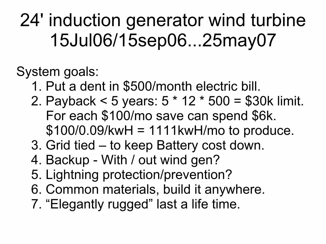
24' induction generator wind turbine15Jul06/15sep06...25may07
System goals:1. Put a dent in $500/month electric bill.2. Payback < 5 years: 5 * 12 * 500 = $30k limit.
For each $100/mo save can spend $6k.$100/0.09/kwH = 1111kwH/mo to produce.
3. Grid tied – to keep Battery cost down.4. Backup - With / out wind gen?5. Lightning protection/prevention?6. Common materials, build it anywhere.7. “Elegantly rugged” last a life time.
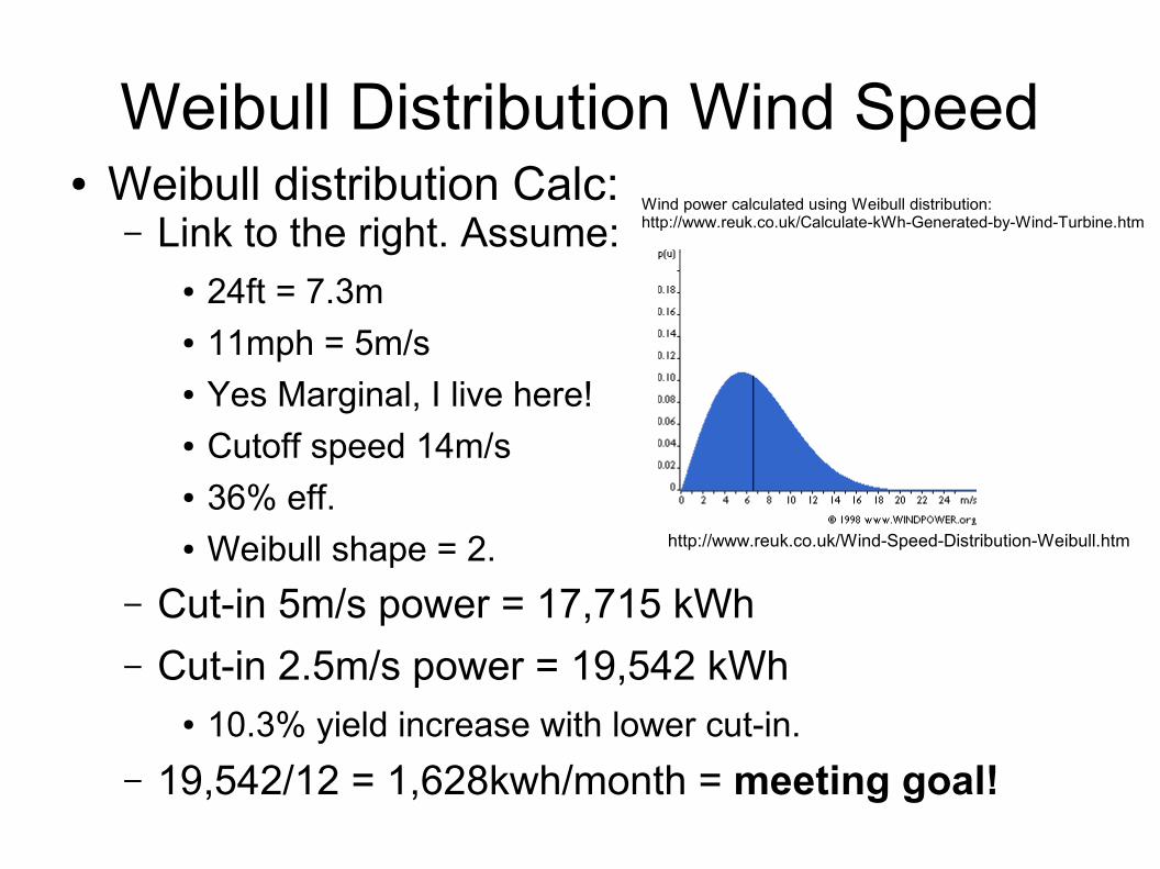
Weibull Distribution Wind Speed● Weibull distribution Calc:
– Link to the right. Assume:● 24ft = 7.3m● 11mph = 5m/s● Yes Marginal, I live here!● Cutoff speed 14m/s● 36% eff.● Weibull shape = 2.
– Cut-in 5m/s power = 17,715 kWh– Cut-in 2.5m/s power = 19,542 kWh
● 10.3% yield increase with lower cut-in.– 19,542/12 = 1,628kwh/month = meeting goal!
http://www.reuk.co.uk/Wind-Speed-Distribution-Weibull.htm
Wind power calculated using Weibull distribution:http://www.reuk.co.uk/Calculate-kWh-Generated-by-Wind-Turbine.htm
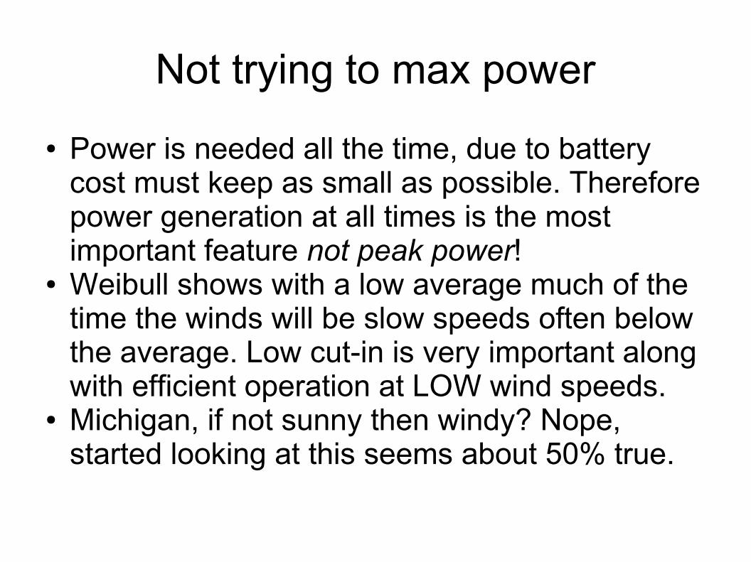
Not trying to max power● Power is needed all the time, due to battery
cost must keep as small as possible. Therefore power generation at all times is the most important feature not peak power!
● Weibull shows with a low average much of the time the winds will be slow speeds often below the average. Low cut-in is very important along with efficient operation at LOW wind speeds.
● Michigan, if not sunny then windy? Nope, started looking at this seems about 50% true.
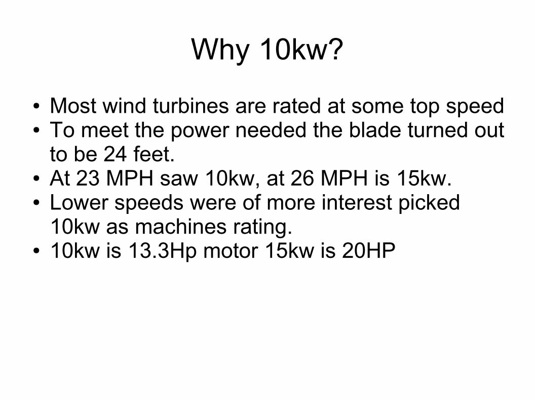
Why 10kw?● Most wind turbines are rated at some top speed● To meet the power needed the blade turned out
to be 24 feet.● At 23 MPH saw 10kw, at 26 MPH is 15kw.● Lower speeds were of more interest picked
10kw as machines rating.● 10kw is 13.3Hp motor 15kw is 20HP

What generator to use?Grid tied required.
●Two choices: Induction motor or Axial PMA● PMA requires Power electronics to Grid tie.
– Assuming No pitch control.● Induction motor connects directly to power line
without electronics. Requires Pitch control.● Tower, supports, battery, blades cost the same.● What are the pros and cons of each generator?
– Next two pages show cost of the bigger items, and things that came to mind. Not super detailed costing.

Permanent Magnet Alternator (PMA)● Two Grid tied inverters: Fronius IG 5100; 240v $2,995.95 ea
– DC input voltage 450v max, 150v min– All power conversion has efficiency hit 10%?– How to control like MPPT to keep gen properly loaded?
● Should keep stator heating issue down.– Limit grid feed to 5kw (18mph), then only one inverter needed.
● Limits usefulness of this size of system to low winds.● PMA output voltage is directly proportional to speed, at 23mph output
10kw must be limited to highest operating voltage of the inverter 450v.– Furled operation above 23 mph.
● BU load dump required, Grid down where does power go? $200 - $400 cost.
● At 5.5mph cut-in the low 450/4.2 = 107v < 150v, need voltage boost to work. 250W or $500. Or raise cut-in to 7.6mph. Loosing 5% eff.
● PMA – two stators: 6 spools wire, 80 magnets, steal plates, epoxy.– $2,520 excluding steal, bolts... (4x cost of 1kw on forcefield)– Parts based on 2x otherpower 20' gen design.
● Run each stator with own inverter, redundant power system.● Total cost > $9,000. Looks like a 8kw gen, no data on 20' design.
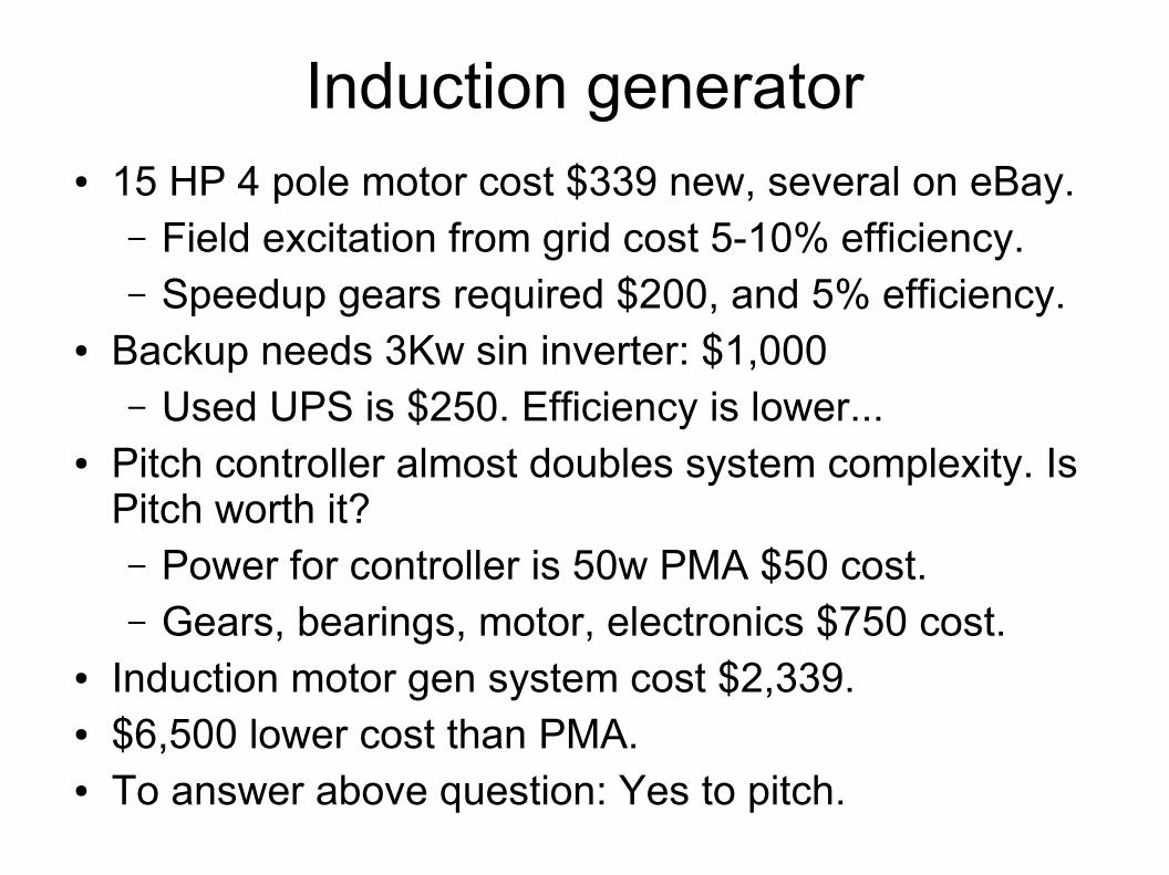
Induction generator● 15 HP 4 pole motor cost $339 new, several on eBay.
– Field excitation from grid cost 5-10% efficiency.– Speedup gears required $200, and 5% efficiency.
● Backup needs 3Kw sin inverter: $1,000– Used UPS is $250. Efficiency is lower...
● Pitch controller almost doubles system complexity. Is Pitch worth it?– Power for controller is 50w PMA $50 cost.– Gears, bearings, motor, electronics $750 cost.
● Induction motor gen system cost $2,339.● $6,500 lower cost than PMA.● To answer above question: Yes to pitch.

In
duct
ion
mot
or
Pitch control
UPS
Line
Towercontrol
Battery
Loads
24' wind turbine system design
Speedup gear
Looks simple? That is the whole idea. Assuming can back feeding power through UPS to grid.No method to charge battery if grid power down.
Yaw

Wind Turbine Mechanicals
DiffTrans
InductionMotor
BearingYaw servo
Wheel brake – on same shaft as blade
Small Axial gen – power for Pitch
Tower
TowerControllerYaw, PowerWireless
PitchControllerMotorWireless
Rt angle gear part of rear end.
Speed up gear
1800RPM 4 poleor
1100RPM 6 pole
Vehicle rear end
Motor in tower
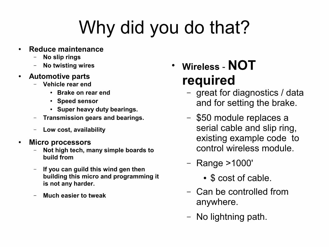
Why did you do that?● Reduce maintenance
– No slip rings– No twisting wires
● Automotive parts– Vehicle rear end
● Brake on rear end● Speed sensor● Super heavy duty bearings.
– Transmission gears and bearings.
– Low cost, availability
● Micro processors– Not high tech, many simple boards to
build from
– If you can guild this wind gen then building this micro and programming it is not any harder.
– Much easier to tweak
● Wireless - NOT required– great for diagnostics / data
and for setting the brake.– $50 module replaces a
serial cable and slip ring, existing example code to control wireless module.
– Range >1000'● $ cost of cable.
– Can be controlled from anywhere.
– No lightning path.
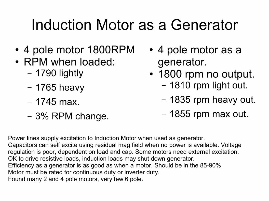
Induction Motor as a Generator● 4 pole motor 1800RPM● RPM when loaded:
– 1790 lightly– 1765 heavy– 1745 max.– 3% RPM change.
● 4 pole motor as a generator.
● 1800 rpm no output.– 1810 rpm light out.– 1835 rpm heavy out.– 1855 rpm max out.
Power lines supply excitation to Induction Motor when used as generator.Capacitors can self excite using residual mag field when no power is available. Voltage regulation is poor, dependent on load and cap. Some motors need external excitation.OK to drive resistive loads, induction loads may shut down generator. Efficiency as a generator is as good as when a motor. Should be in the 85-90% Motor must be rated for continuous duty or inverter duty.Found many 2 and 4 pole motors, very few 6 pole.
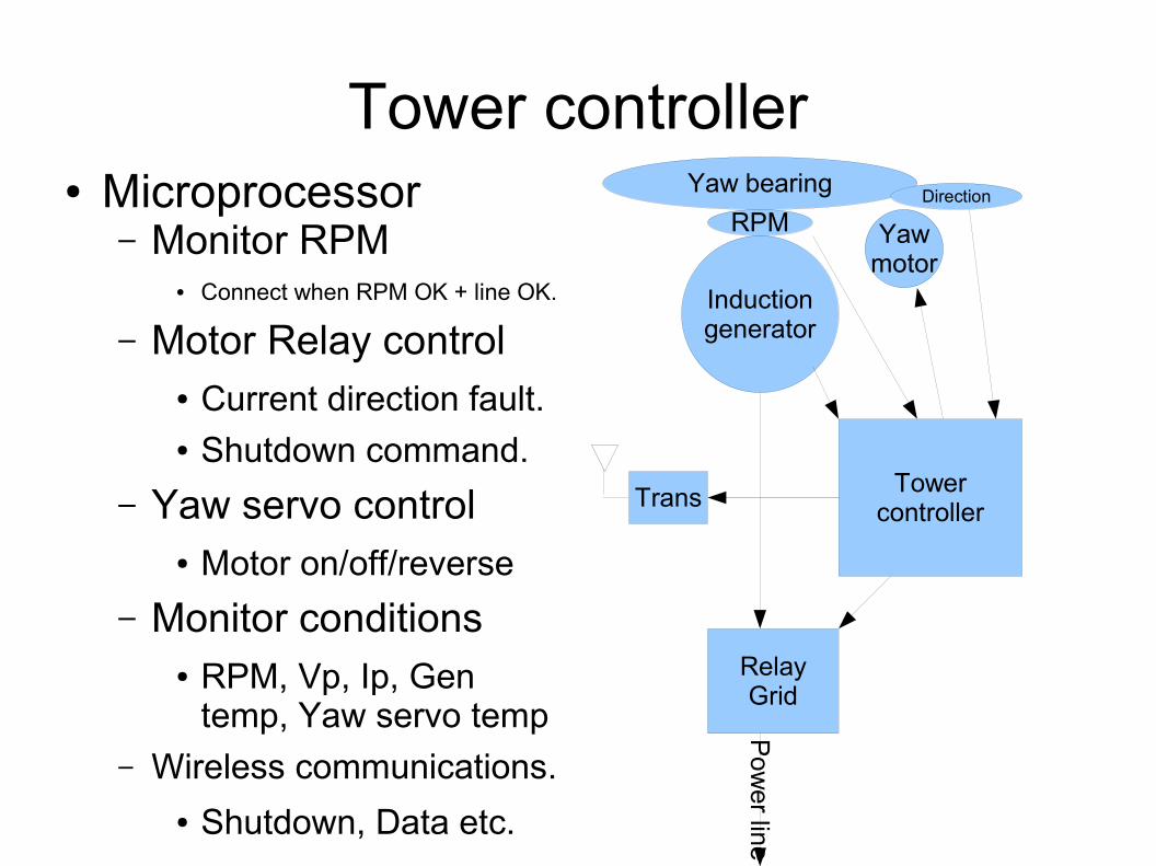
Tower controller● Microprocessor
– Monitor RPM● Connect when RPM OK + line OK.
– Motor Relay control● Current direction fault.● Shutdown command.
– Yaw servo control● Motor on/off/reverse
– Monitor conditions● RPM, Vp, Ip, Gen
temp, Yaw servo temp– Wireless communications.
● Shutdown, Data etc.
Inductiongenerator
RPMYaw bearing Direction
Yawmotor
TowercontrollerTrans
RelayGrid
Pow
er line
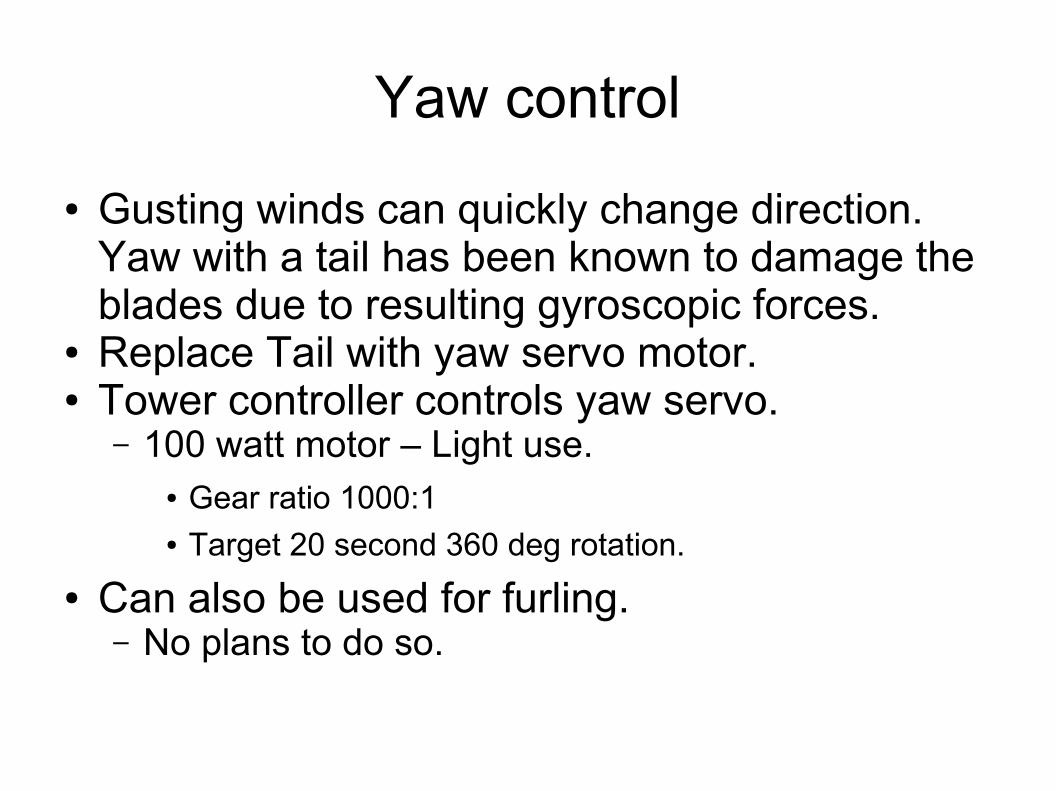
Yaw control● Gusting winds can quickly change direction.
Yaw with a tail has been known to damage the blades due to resulting gyroscopic forces.
● Replace Tail with yaw servo motor.● Tower controller controls yaw servo.
– 100 watt motor – Light use.● Gear ratio 1000:1● Target 20 second 360 deg rotation.
● Can also be used for furling.– No plans to do so.
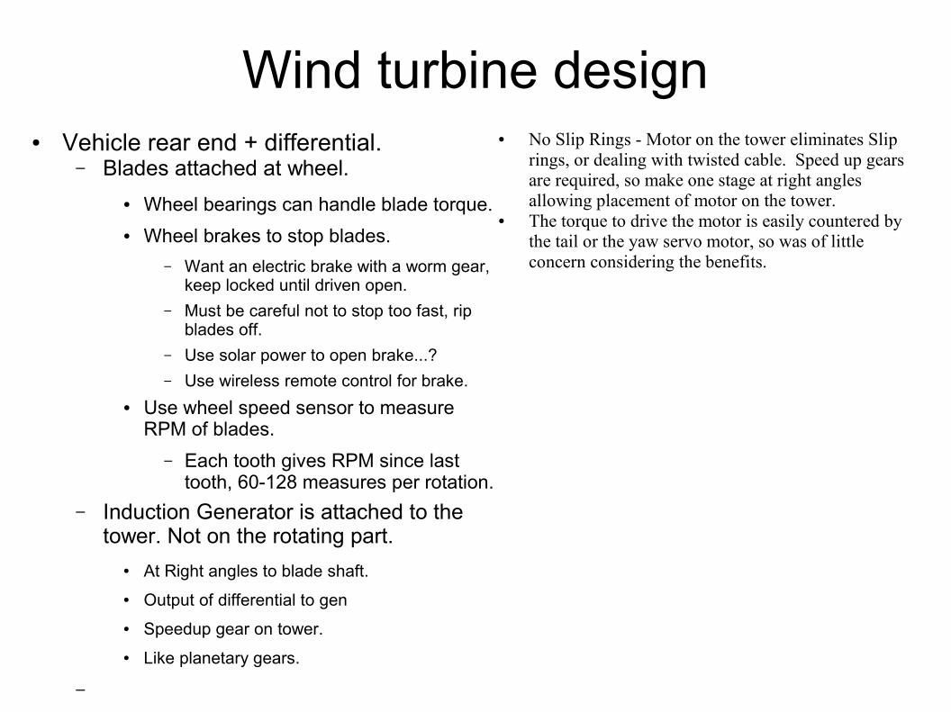
Wind turbine design● Vehicle rear end + differential.
– Blades attached at wheel.● Wheel bearings can handle blade torque.● Wheel brakes to stop blades.
– Want an electric brake with a worm gear, keep locked until driven open.
– Must be careful not to stop too fast, rip blades off.
– Use solar power to open brake...?– Use wireless remote control for brake.
● Use wheel speed sensor to measure RPM of blades.
– Each tooth gives RPM since last tooth, 60-128 measures per rotation.
– Induction Generator is attached to the tower. Not on the rotating part.
● At Right angles to blade shaft.● Output of differential to gen● Speedup gear on tower.● Like planetary gears.
–
● No Slip Rings - Motor on the tower eliminates Slip rings, or dealing with twisted cable. Speed up gears are required, so make one stage at right angles allowing placement of motor on the tower.
● The torque to drive the motor is easily countered by the tail or the yaw servo motor, so was of little concern considering the benefits.
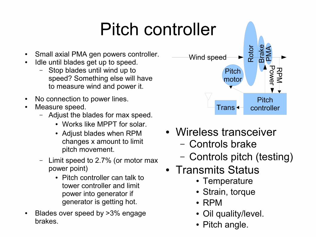
Pitch controller● Small axial PMA gen powers controller.● Idle until blades get up to speed.
– Stop blades until wind up to speed? Something else will have to measure wind and power it.
● No connection to power lines.● Measure speed.
– Adjust the blades for max speed.● Works like MPPT for solar.● Adjust blades when RPM
changes x amount to limit pitch movement.
– Limit speed to 2.7% (or motor max power point)
● Pitch controller can talk to tower controller and limit power into generator if generator is getting hot.
● Blades over speed by >3% engage brakes.
● Wireless transceiver– Controls brake– Controls pitch (testing)
● Transmits Status● Temperature● Strain, torque● RPM● Oil quality/level.● Pitch angle.
Pitchmotor
Pitchcontroller
Bra
keR
otor
PM
A
Wind speed
Trans
Pow
erR
PM
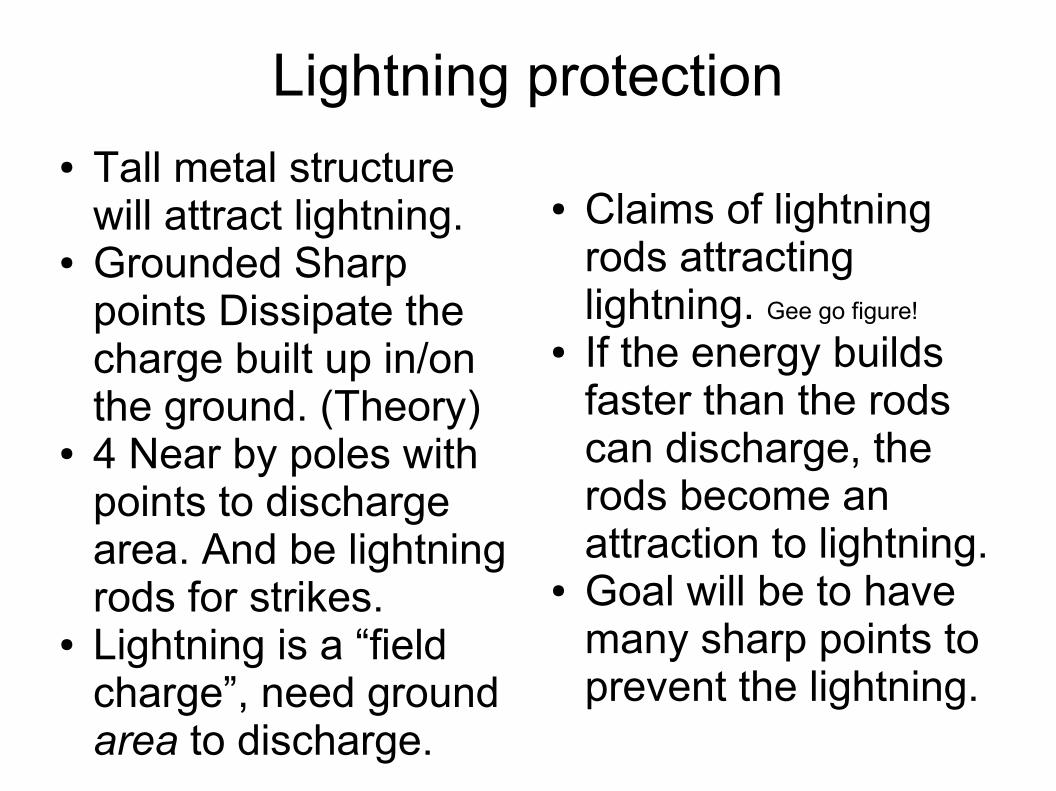
Lightning protection● Tall metal structure
will attract lightning.● Grounded Sharp
points Dissipate the charge built up in/on the ground. (Theory)
● 4 Near by poles with points to discharge area. And be lightning rods for strikes.
● Lightning is a “field charge”, need ground area to discharge.
● Claims of lightning rods attracting lightning. Gee go figure!
● If the energy builds faster than the rods can discharge, the rods become an attraction to lightning.
● Goal will be to have many sharp points to prevent the lightning.

Pitch control by TSR● Must respond to wind
gust to furl the blades.– 4 sec? 90 deg rotation.
● Need nice smooth low drag blade to get TSR = 14, 11.5 is more likely.
● 80 RPM Blade– 5MPH TSR =14– 6MPH TSR =11.5– 10MPH TSR = 7– 14MPH TSR = 5– 23MPH TSR = 3 max HP– 35MPH TSR = 2– 70MPH TSR = 1

● http://www.clemson.edu/scies/wind/Poster-Schmidt.pdf


Wireless remote control● Tower talks to:
– Pitch.– weather station
● Wind direction/speed.– Base station.– Keyfob
● Base talks to:– Weather station– Tower– If necessary Pitch.
● Keyfob controls both pitch and tower sending commands.– Start, Stop, Shutdown.
● Base connects to computer serial port
● Weather station report wind data.
● Pitch talks to tower

Backup system● Battery
– 10kwh– 8 golf cart batteries.– 2 days bu time.– 48v at 225ah battery– Any additional BU
need a larger battery.
● UPS– Larger UPS convert all
power to battery then convert to AC.
● Efficiency hit >25%.– Suggest to use switching
UPS. Stand by pwr <1.7%● Power Relay switches power
from grid to internal.● Size limits 3-5kw range, so will
need several units. Units may NOT be paralleled.
● Shut down UPS at night– Stand by pwr same no load.

Why Use a Gearbox?
The power from the rotation of the wind turbine rotor is transferred to the generator through the power train, i.e. through the main shaft, the gearbox and the high speed shaft, as we saw on the page with the Components of a Wind Turbine. But why use a gearbox? Couldn't we just drive the generator directly with the power from the main shaft? If we used an ordinary generator, directly connected to a 50 Hz AC ( alternating current ) three phase grid with two, four, or six poles, we would have to have an extremely high speed turbine with between 1000 and 3000 revolutions per minute (rpm), as we can see in the page on Changing Generator Rotational Speed. With a 43 metre rotor diameter that would imply a tip speed of the rotor of far more than twice the speed of sound, so we might as well forget it. Another possibility is to build a slow-moving AC generator with many poles. But if you wanted to connect the generator directly to the grid, you would end up with a 200 pole generator (i.e. 300 magnets) to arrive at a reasonable rotational speed of 30 rpm. Another problem is, that the mass of the rotor of the generator has to be roughly proportional to the amount of torque (moment, or turning force) it has to handle. So a directly driven generator will be very heavy (and expensive) in any case.

Prototype at half blade size?● 5 hp 12 foot blades● 160 RPM at 5 MPH.● 3600 RPM motor to
keep the gear ratio the same.
● 3.5 Kw at 25 mph.
● Hardware design will be the same for prototype and final. Will allow to upgrade to final if desired.
● Blades – wood carved. CNC so can duplicate quickly.
● Pitch control is going to take some work. Expect to break blades.

Why no actual design?● Use Local materials● Don't know what is
available yet.
● Will this work?