11 pages, , ~2 mb - third millennium engineering
TRANSCRIPT

Third Millennium Engineering www.tmeplano.com
Photonic Doppler Velocimeter (PDV) Receiver and Transceiver ModBlocks
Helping customers create and manufacture advanced technology products for our future
Third Millennium Engineering
www.tmeplano.com PDV ModBlocks
Page 2 of 18 2AM2CA1505A‐PDVModBlocks
PDV Receiver and Transceiver ModBlocks This document describes Photonic Doppler Velocimeter (PDV) receiver and transceiver ModBlock products
available from Third Millennium Engineering (TME). A PDV System Overview is provided on page 15. A PDV receiver is used with long coherence length C-band laser, fiber optic probe, oscilloscope, software, and a trigger to implement a complete PDV system. A PDV transceiver is a PDV receiver with a built-in laser. ModBlock is the name for a modular system of TME standard products.
TME can supply custom PDV receiver and transceiver models in the 1310 nm or 1550 nm band with choices of 2.5 GHz or 10 GHz class analog PIN or APD receivers, AC or DC coupled RF outputs, and structured for use with back-reflecting (BR) or non-back-reflecting (NBR) probes and homodyne or heterodyne operation. TME recommends 1550 nm AC coupled PIN receivers and use of NBR probes for most applications. PDV transceivers are offered with 20, 50, or 75 mW coherent lasers.
Recommended Models, Price, and Delivery PDV receiver model F179A is recommended for most PDV applications because it is versatile. It is a 1550 nm
band 10 GHz class AC coupled PIN receiver capable of both homodyne and heterodyne operation and usable with either BR or NBR probes. High power optical splitters are also available to operate multiple receivers from one high power laser. Model F313A is a dual 1x4 splitter and model F318A is a single 1x8 splitter.
PDV transceiver model F239B is recommended for simple PDV applications. It is a 1550 nm band 10 GHz class AC coupled PIN receiver with an internal 50 mW coherent laser. The receiver is structured for homodyne operation and for use with NBR probes.
PDV receiver model 2G179PDV4 is a turnkey 4-channel rack-mountable PDV receiver system. It consists of four F179A receivers, a F313A dual 1x4 splitter, power supply, fiber cleaning kits, and all needed microwave, fiber optic, LAN, and DC power cable assemblies. The 2G179PDV4 price is $63,350 and has an 8-10 week standard delivery.
PDV receiver model 2G179PDV8 is a turnkey 8-channel rack-mountable PDV receiver system. It consists of eight F179A receivers, a F318A dual 1x4 splitters, power supplies, fiber cleaning kits, and all needed microwave, fiber optic, LAN, and DC power cable assemblies. The 2G179PDV8 price is $124,585 and has an 8-10 week standard delivery.
A single F179A PDV receiver price is $15,575 and the A320A power supply for it is $325 with an 8-10 week standard delivery, which is typically used as a spare receiver.
PDV transceiver model 2G239PDV1B is a turnkey 1-channel PDV transceiver system. It consists of an F239B transceiver, power supply, fiber cleaning kits, and all needed microwave, fiber optic, and LAN cable assemblies. The 2G239PDV1B price is $23,250 and has a 10-12 week standard delivery.
Model 2G179PDV4A PDV Receiver 4-Channel Analog PDV PIN Receiver, Homodyne/Heterodyne, 10 GHz Class, AC-coupled
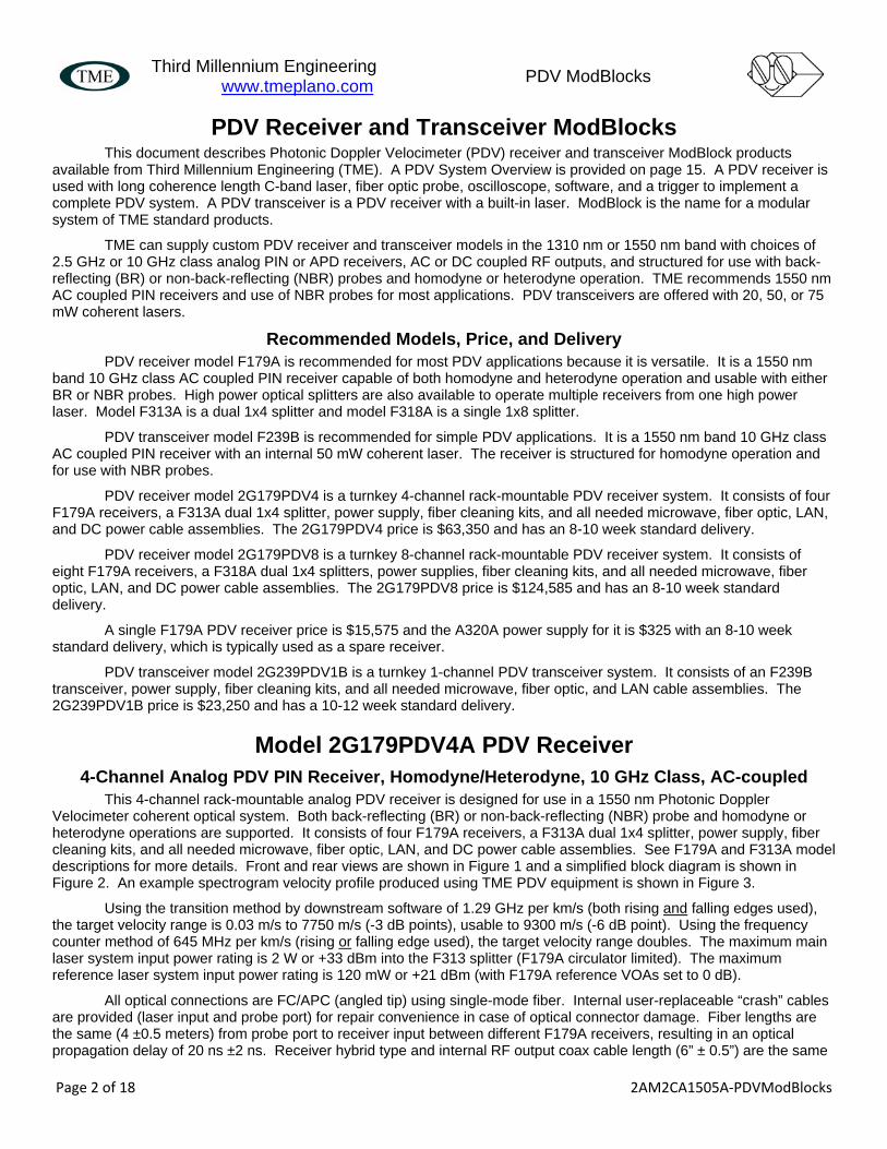
This 4-channel rack-mountable analog PDV receiver is designed for use in a 1550 nm Photonic Doppler Velocimeter coherent optical system. Both back-reflecting (BR) or non-back-reflecting (NBR) probe and homodyne or heterodyne operations are supported. It consists of four F179A receivers, a F313A dual 1x4 splitter, power supply, fiber cleaning kits, and all needed microwave, fiber optic, LAN, and DC power cable assemblies. See F179A and F313A model descriptions for more details. Front and rear views are shown in Figure 1 and a simplified block diagram is shown in Figure 2. An example spectrogram velocity profile produced using TME PDV equipment is shown in Figure 3.
Using the transition method by downstream software of 1.29 GHz per km/s (both rising and falling edges used), the target velocity range is 0.03 m/s to 7750 m/s (-3 dB points), usable to 9300 m/s (-6 dB point). Using the frequency counter method of 645 MHz per km/s (rising or falling edge used), the target velocity range doubles. The maximum main laser system input power rating is 2 W or +33 dBm into the F313 splitter (F179A circulator limited). The maximum reference laser system input power rating is 120 mW or +21 dBm (with F179A reference VOAs set to 0 dB).
All optical connections are FC/APC (angled tip) using single-mode fiber. Internal user-replaceable “crash” cables are provided (laser input and probe port) for repair convenience in case of optical connector damage. Fiber lengths are the same (4 ±0.5 meters) from probe port to receiver input between different F179A receivers, resulting in an optical propagation delay of 20 ns ±2 ns. Receiver hybrid type and internal RF output coax cable length (6” ± 0.5”) are the same

Third Millennium Engineering
www.tmeplano.com PDV ModBlocks
Page 3 of 18 2AM2CA1505A‐PDVModBlocks
between different F179A receivers, resulting in an optical receiver input to front panel RF Output connector propagation delay of ~2 ns.
Figure 1. 2G179PDV4A, 4-Channel PDV Receiver, front and rear views
(microwave and fiber optic cables not shown)
Figure 2. 2G179PDV4A, simplified block diagram
Third Millennium Engineering
www.tmeplano.com PDV ModBlocks
Page 4 of 18 2AM2CA1505A‐PDVModBlocks
Fig. 2. Photon Doppler Velocimetry spectrogram acquired along the symmetry axis of a 65‐mm diameter copper shaped charge jet.
from “Photon Doppler Velocimetry (PDV) Characterization of Shaped Charge Jet Formation”, M.B. Zellner and G.B. Vunni, US Army Research Laboratory, Aberdeen Proving Ground, MD 21005‐5068, United States
Figure 3. Example spectrogram velocity profile produced using TME PDV equipment
Model F179A PDV Receiver ModBlock Analog PDV PIN Receiver, Homodyne/Heterodyne, 10 GHz Class, AC-coupled
This analog PDV receiver is designed for use in a 1550 nm Photonic Doppler Velocimeter coherent optical system. Both back-reflecting (BR) or non-back-reflecting (NBR) probe and homodyne or heterodyne operations are supported. The receiver contains a linear 10 GHz class PIN photodiode with trans-impedance amplifier for C-band operation (1528 to 1563 nm, usable to 850 nm). The bandwidth is ~35 KHz (AC coupled, 0.1 uF) to over 10 GHz at the -3 dB points (~12 GHz at -6 dB point). The receiver also has optical input power meter circuitry with a precision logarithmic converter to provide dBm readout values. The receiver is preceded by a 90/10% coupler, two electronic variable optical attenuators (main VOA and reference VOA) with 30 dB minimum range, a 500 mW 3-port circulator, reference optical switch, and a 1% tap coupler.
Using the transition method by downstream software of 1.29 GHz per km/s (both rising and falling edges used), the target velocity range is 0.03 m/s to 7750 m/s (-3 dB points), usable to 9300 m/s (-6 dB point). Using the frequency counter method of 645 MHz per km/s (rising or falling edge used), the target velocity range doubles. The maximum main laser input power rating is 500 mW or +27 dBm (circulator and/or 1% coupler limited) with 1 to 2 dB loss to probe port. The maximum reference laser input power is 30 mW or +15 dBm (with reference VOA set to 0 dB).

Third Millennium Engineering
www.tmeplano.com PDV ModBlocks
Page 5 of 18 2AM2CA1505A‐PDVModBlocks
All optical connections are FC/APC (angled tip) using single-mode fiber. Internal user-replaceable “crash” cables are provided (laser input and probe port) for repair convenience in case of optical connector damage. Fiber lengths are the same (4 ±0.5 meters) from probe port to receiver input between different F179A units, resulting in an optical propagation delay of 20 ns ±2 ns. Receiver hybrid type and internal RF output coax cable length (6” ± 0.5”) are the same between different F179A units, resulting in an optical receiver input to front panel RF Output connector propagation delay of ~2 ns.
The probe port reflected input power range is 7 dBm maximum (main attenuator set to 0 dB) to -15 dBm minimum and the single-ended AC coupled RF output voltage is ~536 mVpp @ 0 dBm input. A rear panel auxiliary DC output (SMA connector) is provided for optical input power level monitoring (dBm) by external hardware.
The F179A is packaged in a black 1.72”H x 4.19”W x 10.70”D modular aluminum chassis, allowing simple horizontal or vertical stacking for as many channels as desired. It is daisy-chain powered by 12 volts DC ±3 volts DC (9 to 15 VDC) from the rear panel using an external AC-DC power supply. Power is controlled by a front panel “Power” pushbutton with green LED and toggle operation (press for on, press again for off). The F179A is also computer controllable via Ethernet from a rear panel RJ45 connector. Front panel bi-color LEDs are provided to indicate LAN operations.
F179A front chassis view, graphic layouts, and simple block diagram
1U, quarter-rack, 10.7” deep

Third Millennium Engineering
www.tmeplano.com PDV ModBlocks
Page 6 of 18 2AM2CA1505A‐PDVModBlocks
A front panel tri-color “Over/OK/LOS” LED monitors the optical input power level to the receiver. Green indicates optical input power exists and is within the normal operating range for the receiver (+3 dBm to -25 dBm). Red indicates optical input power exists, but is too high (>+3 dBm), risking receiver damage. Yellow indicates low or no optical input power (< -25 dBm).
Two front panel 3 digit numeric readouts display the VOA setting (main or reference in VDC) and received optical power (in dBm). Front panel pushbuttons with up and down arrows allow attenuation adjustment for the VOA indicated by the green “Main” and “Ref” LEDs. Pressing the up button or down button for more than 3 seconds changes the step size from fine steps to coarse steps until the button is released. Pressing both up and down pushbuttons at the same time toggles the “Main” and “Ref” LEDs, attenuator display reading, and up/down pushbutton operation between the main VOA and the reference VOA. Pressing both up and down pushbuttons for more than 3 seconds is also used to toggle the display off or on.
A front panel “Mode” pushbutton with green LED and toggle operation controls an optical switch to select the reference laser light source. When the pushbutton LED is off, the F179A is configured for heterodyne operation and uses the front panel reference laser input as the reference source. When the pushbutton LED is on, the F179A is configured for homodyne operation and uses the tap coupler (main laser input) as the reference source.
The F179A has four operating modes: (Mode 1) heterodyne for use with NBR probe, (Mode 2) heterodyne for use with BR probe, (Mode 3) homodyne for use with NBR probe, and (Mode 4) homodyne for use with BR probe. Mode 1 is configured when the “Mode” pushbutton LED is off and the reference laser input and NBR probe are used. Mode 2 is configured when the “Mode” pushbutton LED is off and the reference laser input and BR probe are used. Mode 3 is configured when the “Mode” pushbutton LED is on and an NBR probe is used (no reference laser used). Mode 4 is configured when the “Mode” pushbutton LED is off and a BR probe is used (no reference laser used).
In Mode 1 (heterodyne, NBR), a coherent interferometer condition occurs in the 90/10% coupler by combining the reference laser input light and the reflected target light picked up by the probe. The main VOA is set to 0 dB and increased if the probe light is too strong for the receiver. The reference VOA is used to roughly match the reference laser light and the probe light amplitudes.
In Mode 2 (heterodyne, BR), a coherent interferometer condition occurs at the probe tip by combining the main laser light reflected at the probe tip (due to Fresnel loss) and the reflected target light picked up by the probe. The interfered light at the probe tip is combined with the reference laser input light in the 90/10% coupler. The main VOA is set to 0 dB and increased if the probe light is too strong for the receiver. The reference VOA is used to roughly match the reference laser light and the probe light amplitudes.
In Modes 1 and 2, the reference laser wavelength is offset from the main laser wavelength to mix the beat signal with a side band. This is done to determine the direction of motion, particularly for low velocity mechanical vibration measurements, and to downshift for recording much higher velocities. See workshop and conference papers from the PDV community for more details.
In Mode 3 (homodyne, NBR), a coherent interferometer condition occurs in the 90/10% coupler by combining a small (1% tap) portion of the main laser input light and the reflected target light picked up by the probe. The main VOA is set to 0 dB and increased if the probe light is too strong for the receiver. The reference VOA is used to roughly match the tapped main laser light and probe light amplitudes.
In Mode 4 (homodyne, BR), a coherent interferometer condition occurs at the probe tip by combining the main laser light reflected at the probe tip (due to Fresnel loss) and the reflected target light picked up by the probe. Because the reflected light due to Fresnel loss is fairly high (6% of the main laser light), the main VOA is adjusted to insure the receiver input power level is in a safe range. The reference laser and reference VOA are not used.
F179A Basic Specifications Parameter Description
Chassis • Anodized aluminum enclosure materials, ESD compliant antistatic surfaces • Black aluminum color with white laser engraved graphics on front and rear panels
Environment
• For indoor use in office, lab, factory, or vehicle environments. Not for outdoor use. • Operating temperature range: 5°C to 45°C minimum • Storage temperature range: -20°C to +70°C minimum • Relative humidity range: 10% to 90% minimum, non-condensing, minimum • Shock and vibration range: 2G’s minimum

Third Millennium Engineering
www.tmeplano.com PDV ModBlocks
Page 7 of 18 2AM2CA1505A‐PDVModBlocks
Parameter Description Cooling Conduction and convection (no fans)
Connectors • Front panel: all optical and microwave I/O connectors • Rear panel: DC power inlet and RJ45-8 LAN Port
Power
• Power port via two rear panel 2-pin “Utility” connectors, daisy-chained • 12 volts DC ±3 volts DC (9 to 15 VDC) • Front panel bi-color “Power” status LED • Front panel power switch
Computer Control
• 10 Base-T LAN port, internal controller with non-volatile memory, C-program • Manages all manual controls and displays for local operation • Provides remote computer operation of all manual control and display functions • Front panel bi-color “Link/Act” status LED, monitors LAN link and activity • Front panel bi-color “Rem/LLO” status LED, monitors remote and local lockout status • GUI provided for remote control via LAN port
Safety Ratings
Not required for 12 VDC powered ModBlocks. For industrial use only by customer and their sub-contractors. Customer assumes liability for use. However, safety agency approved components (UL, CSA, VDE, etc.) and safe engineering practices used for grounding, labeling, flammability, insulation, wiring, etc. Six-sided aluminum enclosure, and good engineering practices used for conductive and radiative EMI/RFI performance.
Documentation
Simple operating manual includes operating instructions, detailed descriptions, block diagrams, performance specifications, pictorial views, and GUI software description. Requires user to have basic knowledge of high-speed fiber optics, electronics, and related test equipment (brief explanations without lengthy tutorials).
Shipping
Can be shipped via commercial carriers with normal cushioned packing methods. Cover all microwave and optical ports with anti-static connector caps and then enclose unit in an anti-static bag or container prior to packing for shipment. ModBlocks contain no hazardous materials, liquids, etc.
F179A Performance Specifications Parameter Value Units Qualifier
Model Number F179A - - Channels 1 - -
Probe Type Back-reflecting or Non-back-reflecting - -
Fiber Type Single-mode - - Optical Connector Type FC/APC, ceramic ferrule - (angled tip) Fiber length, probe port or reference laser input to receiver 5 ± 0.5 m - Optical propagation delay (SMF), probe port or reference laser input to receiver 25 ± 2.5 ns typical
Fiber length, main laser input to receiver 6 ± 0.5 m - Optical propagation delay (SMF), main laser input to receiver 30 ± 3 ns typical
Wavelength Range 1528 to 1563 nm minimum Polarity, O-to-E conversion Non-inverting - - Coupler Type, tap and 90/10% combiner Fused Bi-conical Taper - - Tap Coupler Ratio 1 % typical Combiner Coupler Ratio 90/10 % typical Circulator Type 3-port - - VOA Type, main and reference MEMS, analog control - - VOA Attenuation Range 0 to 30 dB 0 to 3V control VOA Control Step Size 10 mV typical Receiver Type PIN-TIA - -
Main Laser Input Power, maximum rating CW 500 27
mW dBm -

Third Millennium Engineering
www.tmeplano.com PDV ModBlocks
Page 8 of 18 2AM2CA1505A‐PDVModBlocks
Parameter Value Units Qualifier Reference Laser Input Power, maximum rating CW 30
15 mW dBm ref. VOA = 0
Reference Laser Input Power, maximum rating CW 500 27
mW dBm ref. VOA > 12 dB
Probe Port Input Power, damage threshold rating CW (normally by probe back-reflection)
6 4
dBm mW
typical, main VOA = 0
Probe Port Input Power, maximum rating CW (normally by probe back-reflection)
5 3
dBm mW
typical, main VOA = 0
Probe Port Input Power, maximum rating CW 500 27
mW dBm
typical, main VOA > 25dB
Probe Port Input Power, minimum (normally by probe back-reflection)
-17.5 18
dBm uW
typical, -20 dBm at receiver input, main VOA = 0
Optical Insertion Loss, typical Main Laser Input to Probe Port 1.2 dB -
Optical Insertion Loss, typical Main Laser Input to Receiver via tap coupler
33 63 dB ref. VOA = 0
ref. VOA =30 dB Optical Insertion Loss, typical Reference Laser Input to Receiver
13 43 dB ref. VOA = 0
ref. VOA =30 dB Optical Insertion Loss, typical Probe Port to Receiver 2.2 dB main VOA = 0
Optical Return Loss, Laser Input or Probe Port 50 dB minimum
Sensitivity, 10-10 BER, at probe port -16 -17 dBm minimum
typical Receiver Sensitivity, 10-10 BER (receiver only)
-18 -19 dBm minimum
typical
Receiver Responsivity 0.7 0.8 mA/mW minimum
typical
Receiver Trans-impedance 400 500 650
ohms minimum typical maximum
Receiver Gain Flatness ±0.75 dB typical
Receiver Bandwidth 9.5 10 12
GHz minimum typical, -3 dB pointtypical, -6 dB point
Receiver Low Frequency Cutoff 35 KHz typical, -3 dB point Target Velocity Range, transition method, 1.29 GHz per km/s 0.03 to 7,750 meters/
second typical, -3 dB points
Target Velocity Range, counter method, 645 MHz per km/s 0.06 to 15,500 meters/
second typical, -3 dB points
Receiver Linearity, -15 to 0 dBm <1 % typical Receiver Group Delay, <7 GHz ±10 ps typical Receiver Noise Figure 3 dB typical RF Output Connector SMA female, 50 ohms - - RF Output Coupling AC, 0.1 uF - -
RF Output Voltage, typical (receiver input to RF output)
900 28 13
mVpp 0 dBm input -16 dBm input -20 dBm input
RF Output Voltage, typical (probe port input to RF output)
536 16 8
mVpp 0 dBm input -16 dBm input -20 dBm input
RF Output Return Loss 10 15 dB minimum
typical

Third Millennium Engineering
www.tmeplano.com PDV ModBlocks
Page 9 of 18 2AM2CA1505A‐PDVModBlocks
Parameter Value Units Qualifier DC Output Connector SMA female - - DC Output Level, 0 dBm input 1.00 V - DC Output Sensitivity 20 mV/dB typical
DC Power Input Voltage 12 9 to 18 V nominal
range
DC Power Input Current at 12V 1.0 0.5 A maximum
typical Weight 3 pounds maximum Dimensions 1.72H x 8.38W x 10.70D Inches nominal
Model F313A PDV Splitter ModBlock Dual 1x4 Coupler, Single-mode
The F313A is a passive fiber optic dual 1x4 coupler using single-mode (SM) fiber. The coupling ratio is 25/25/25/25% (equal splits). A coupler can be used to split an incoming light source into two parts or to combine two light sources into a single part. Note: model F318A is a single 1x8 splitter.
F313A chassis views, graphics layout, and simple block diagram
1U, quarter-rack, 6.7” deep
Rear View
Third Millennium Engineering
www.tmeplano.com PDV ModBlocks
Page 10 of 18 2AM2CA1505A‐PDVModBlocks
F313A Specifications Parameter Value Units Qualifier
Model Number F313A - - Channels 2 - - Coupler Type 1x4 fused bi-conical taper - - Fiber Type single-mode - - Wavelength Range (per spec, usable beyond) 1510-1590 nm -
Coupling Ratio 25/25/25/25 % Optical Power 4 watts maximum Insertion Loss 7.8 dB maximum Optical Return Loss 55 dB minimum Directivity 55 dB minimum Polarization Dependent Loss 0.20 dB maximum
Connectors, fiber optic FC/APC ceramic ferrule - (angled tip)
Power Requirements None - - Weight 1 pound maximum Dimensions 0.85H x 4.19W x 6.70D Inches nominal
Model F239B PDV Transceiver ModBlock The F239B system (2G239PDV1B) consists of a PDV receiver, an A320A power supply, and related cable
assemblies and cleaning kits. A simplified block diagram of the F239B is shown in Figure 4. Front and rear view pictures of the instruments with are shown in Figure 5 and Figure 6. A simplified block diagram of the F239B is shown in Figure 4.
The F239B is an analog receiver with a 50 mW laser designed for use in a 1550 nm Photonic Doppler Velocimeter coherent optical system that uses a non-back-reflecting (NBR) probe. Target velocity range is 0.05 to 7500 m/s (AC coupled, ~35 KHz cutoff) using the both transitions per cycle software method and 0.1 to 15,000 m/s using a frequency counter software method. Maximum rated laser input power is 500 mW or +27 dBm (circulator and/or coupler limited) with ~2 dB loss from laser port to probe port. The probe port reflected input power range is 7 dBm maximum to -15 dBm minimum.
The receiver contains a linear 10 GHz class PIN photodiode for C-band (1528 to 1563 nm) operation with trans-impedance amplifier (TIA). It is preceded by a 50% coupler, variable optical attenuator (VOA), 3-port circulator, and a 1% tap coupler. Front panel FC/APC fiber optic connectors are provided for “Laser Output”, “Laser Input” and “NBR Probe” ports. Front panel SMA connectors are provided for “RF Out” (PDV signal going to oscilloscope) and “DC Out” (voltage proportional to received optical power).
A coherent interferometer condition occurs in the 50% coupler by combining the tapped laser input light and reflected target light from the NBR probe. The VOA is used to roughly match their amplitudes. All optical connections are FC/APC (angled tip) using single-mode fiber. Internal “crash” cables are provided (laser input and probe port) for repair convenience in case of optical connector damage. The RF output is single-ended and AC coupled. A front panel auxiliary DC output is provided for optical input power level monitoring by external hardware.
A 1550 nm 50 mW coherent laser (1 MHz typ. line width) is provided for use as the light source for the PDV system. It is connected via a fiber optic cable on the front panel so that an external laser can be used if needed. The laser temperature is stabilized via a closed loop thermistor and thermo-electric cooler control circuit. The laser power output is stabilized using a closed loop photodiode monitor and laser current driver circuit.
Front panel pushbuttons and a 3-digit numeric readout provide viewing of received optical power monitoring, manual attenuator (VOA) control, and laser output power, which can also be used remotely via a TME GUI. The mode pushbutton changes the display and a bi-color “Mode” LED (along with front panel graphics) indicates the parameter being displayed. Green indicates Received Power monitor mode (-50 to +3 dBm range), yellow indicates Attenuator Control mode, red indicates laser power mode, and dark indicates off mode. Pushbuttons with up and down arrows allow attenuation adjustment for the yellow mode. The mode pushbutton is also used to turn the display off. A “Laser Enable” lighted pushbutton switch operates the internal 50 mW CW laser.

Third Millennium Engineering
www.tmeplano.com PDV ModBlocks
Page 11 of 18 2AM2CA1505A‐PDVModBlocks
Figure 4. F239B, simplified block diagram
Five front panel bi-color LED indicators are provided for status monitoring.
The “Mode” LED indicates the parameter being displayed on the 3 digit display. Green indicates “Received Power dBm” monitor mode, yellow indicates “Attenuator Control VDC” mode, red indicates “Laser Power dBm”, and dark indicates off mode.
The “Over/OK” LED monitors the optical input power level to the internal receiver hybrid. Green indicates optical input power exists and is within the normal operating range for the receiver. Red indicates optical input power exists, but is too high (over +3 dBm), risking receiver damage. Yellow indicates no (or too low) optical input power (less than -30 dBm).
The “Rem/LLO” LED is dark unless the GUI is being used for remote control. Green indicates the GUI is being used (remote control) and yellow indicates the GUI has issued a “local lock-out” which disables all front panel pushbuttons except the “Mode” button.
The “Link/Act” LED is dark unless the LAN feature is being used for remote control via the GUI. Green indicates a hardware connection exists to a router. Blinking yellow indicates the GUI is in control of the F239B.
The “Power” LED is green when the internal +5V power exists within ±5% tolerance.

Third Millennium Engineering
www.tmeplano.com PDV ModBlocks
Page 12 of 18 2AM2CA1505A‐PDVModBlocks
All fiber optic connections are implemented with proper cleaning and single-mode fiber with narrow key FC/APC (angled tip) connectors. Internal “crash” cables are provided (laser input, laser output, and probe ports) for repair convenience in case of optical connector damage.
Figure 5. F239B, 1-Channel PDV Transceiver, front and rear views
Figure 6. F239B, 1-Channel PDV Transceiver, front and rear panel views

Third Millennium Engineering
www.tmeplano.com PDV ModBlocks
Page 13 of 18 2AM2CA1505A‐PDVModBlocks
The front panel “RF Out” and “DC Out” connectors are SMA female. The “RF Out” is used to deliver the PDV electrical signal to an oscilloscope or digitizer. The “DC Out” is used for optical input power level monitoring by external user hardware. The LAN port is a standard RJ45 8-pin connector provided for computer GUI control via Ethernet.
The F239B is packaged in a black 1.72”H x 8.38”W x 8.70”D modular 1U high chassis allowing simple horizontal or vertical ModBlock stacking. It is daisy-chain powered by 12 volts DC ±3 volts DC (9 to 15 VDC). The 12 VDC port has two 2-pin Molex MicroFit 3.0 connectors, which are internally connected in parallel for “daisy-chain” capability. The pin polarity is marked on the rear panel near the two pins (positive nearest the connector latch). Power originates from a separate desktop style AC to DC converter (A320A). This safety agency approved converter accepts 120/240 VAC (world-wide power) and delivers 12 volts DC at up to 2 amps (24 watts). The instrument draws 24 watts maximum and 12 watts typical.
F239B Basic Specifications Parameter Description
Chassis • Anodized aluminum enclosure materials, ESD compliant antistatic surfaces • Black aluminum color with white laser engraved graphics on front and rear panels
Environment
• For indoor use in office, lab, factory, or vehicle environments. Not for outdoor use. • Operating temperature range: 5°C to 45°C minimum • Storage temperature range: -20°C to +70°C minimum • Relative humidity range: 10% to 90% minimum, non-condensing, minimum • Shock and vibration range: 2G’s minimum
Cooling Conduction and convection (no fans)
Connectors • Front panel: all optical and microwave I/O connectors • Rear panel: DC power inlet and RJ45-8 LAN Port
Power
• Power port via two rear panel 2-pin “Utility” connectors, daisy-chained • 12 volts DC ±3 volts DC (9 to 15 VDC) • Front panel bi-color “Power” status LED • Front panel power switch
Computer Control
• 10 Base-T LAN port, internal controller with non-volatile memory, C-program • Manages all manual controls and displays for local operation • Provides remote computer operation of all manual control and display functions • Front panel bi-color “Link/Act” status LED, monitors LAN link and activity • Front panel bi-color “Rem/LLO” status LED, monitors remote and local lockout status
Safety Ratings
Not required for 12 VDC powered ModBlocks. For industrial use only by customer and their sub-contractors. Customer assumes liability for use. However, safety agency approved components (UL, CSA, VDE, etc.) and safe engineering practices used for grounding, labeling, flammability, insulation, wiring, etc. Six-sided aluminum enclosure, and good engineering practices used for conductive and radiative EMI/RFI performance.
Documentation
Simple operating manual includes operating instructions, detailed descriptions, block diagrams, performance specifications, pictorial views, and GUI software description. Requires user to have basic knowledge of high-speed fiber optics, electronics, and related test equipment (brief explanations without lengthy tutorials).
Shipping
Can be shipped via commercial carriers with normal cushioned packing methods. Cover all microwave and optical ports with anti-static connector caps and then enclose unit in an anti-static bag or container prior to packing for shipment. ModBlocks contain no hazardous materials, liquids, etc.
F239B performance specifications Parameter Value Units Qualifier
Model Number F239B-AC - - Channel Count 1 - - Probe Type Non-back-reflecting - - Fiber Type Single-mode - - Optical Connector Type FC/APC, ceramic ferrule - (angled tip)

Third Millennium Engineering
www.tmeplano.com PDV ModBlocks
Page 14 of 18 2AM2CA1505A‐PDVModBlocks
Parameter Value Units Qualifier Wavelength Range 1528 to 1563 nm minimum Receiver Polarity, O-to-E conversion Non-inverting - - Coupler Type, tap and 50% combiner Fused Bi-conical Taper - - Tap Coupler Ratio 1 % typical Combiner Coupler Ratio 50 % typical Circulator Type 3-port - - VOA Type MEMS, analog control - - VOA Attenuation Range, minimum 0 to 30 dB 0 to 3V control VOA Control Step Size 10 mV typical Laser Type DFB, InGaAsP - - Probe Output Power Range, from internal 50 mW laser
17 and off 50 and off
dBm mW maximum
Laser wavelength 1550.12 nm TEC cooled
Laser Spectral Width @ -3 dB points 5 1 MHz maximum
typical Laser Coherence Length 40 meters minimum Laser Side Mode Suppression Ratio 40 dB minimum Laser Relative Intensity Noise -140 dB/Hz maximum Receiver Type PIN-TIA - -
Laser Input Power, maximum 500 27
mW dBm -
Optical Insertion Loss, Laser Input to Probe Port 1.2 dB typical Probe Port Input Power, damage threshold (normally by probe back-reflection)
8 6
dBm mW typical
Probe Port Input Power, maximum (normally by probe back-reflection)
7 5
dBm mW typical
Probe Port Input Power, minimum (normally by probe back-reflection)
-15 30
dBm uW
typical, -20 dBm at receiver input
Optical Insertion Loss, typical Laser Input to Receiver
23 53 dB VOA = 0
VOA = max. Optical Insertion Loss, Probe Port to Receiver 4.5 dB Typical, VOA=0 Optical Return Loss, Laser Input or Probe Port 50 dB minimum
Sensitivity, 10-10 BER -13 -14 dBm minimum
typical Receiver Sensitivity, 10-10 BER (receiver only)
-18 -19 dBm minimum
typical
Receiver Responsivity 0.7 0.8 mA/mW minimum
typical
Receiver Trans-impedance 400 500 650
ohms minimum typical maximum
Receiver Gain Flatness ±0.75 dB typical
Receiver Bandwidth 9.5 10 GHz minimum
typical Receiver Low Frequency Cutoff ~35 KHz - - Target Velocity Range, transition method, 1.29 GHz per km/s 0.05 to 7,500 meters/
second typical, -3 dB points
Target Velocity Range, counter method, 645 MHz per km/s 0.06 to 15,500 meters/
second typical, -3 dB points
Receiver Linearity, -15 to 0 dBm <1 % typical Receiver Group Delay, <7 GHz ±10 ps typical Receiver Noise Figure 3 dB typical RF Output Connector SMA female, 50 ohms - -

Third Millennium Engineering
www.tmeplano.com PDV ModBlocks
Page 15 of 18 2AM2CA1505A‐PDVModBlocks
Parameter Value Units Qualifier RF Output Coupling AC, 0.1 uF - -
RF Output Voltage, typical (receiver input to RF output)
900 28 13
mVpp 0 dBm input -16 dBm input -20 dBm input
RF Output Voltage, typical (probe port input to RF output)
536 16 8
mVpp 0 dBm input -16 dBm input -20 dBm input
RF Output Return Loss 10 15 dB minimum
typical DC Output Connector SMA female - - DC Output Level, 0 dBm input 1.00 V typical DC Output Sensitivity 20 mV/dB typical
DC Power Input Voltage 12 9 to 18 V nominal
range
DC Power Input Current at 12V 2 1 A maximum
typical Weight 4 pounds maximum Dimensions 1.72H x 8.38W x 8.70D Inches nominal
PDV System Overview A Photonic Doppler Velocimeter (PDV) system is typically used by the “shock physics” community to measure the
velocity of a moving target with high temporal resolution and without physical contact by using coherent light and interferometry. The time duration for a “shot” typically ranges from 100’s of nanoseconds to hundreds of microseconds, although the duration can be much longer.
Figure 7. Basic Homodyne PDV system for an NBR probe
A basic homodyne PDV system typically consists of a high power “Main” coherent laser source, a PDV receiver, a fiber optic probe (NBR or BR type), high-speed real-time oscilloscope (RTO), and post-processing software (produces a velocity profile, typically a “spectrogram”). The RTO usually requires an external trigger signal derived from the moving target. By adding a second low power “Reference” coherent laser source, a heterodyne system can be implemented.

Third Millennium Engineering
www.tmeplano.com PDV ModBlocks
Page 16 of 18 2AM2CA1505A‐PDVModBlocks
Figure 7 shows a basic homodyne PDV system for a NBR probe. Figure 8 shows a basic heterodyne PDV system for a NBR probe. Figure 9 shows a basic homodyne PDV system for a BR probe. “I” means target incident light, “R” means target reflected light, and “BR” means probe reflected light (due to Fresnel loss). Figure 3 shows an example spectrogram velocity profile produced using TME PDV equipment.
Figure 8. Basic Heterodyne PDV system for an NBR probe
Figure 9. Basic Homodyne PDV system for a BR probe

Third Millennium Engineering
www.tmeplano.com PDV ModBlocks
Page 17 of 18 2AM2CA1505A‐PDVModBlocks
Custom PDV Equipment TME can design, produce, and support any kind of custom PDV equipment required, including specialized
research or developmental experimental equipment. An example 4-channel PDV receiver is shown below, which was built using customer specified fiber optic modules.
Third Millennium Engineering Third Millennium Engineering (TME) is a multi-disciplinary Texas-based professional engineering company with
one location in Plano, Texas USA. It is classified as a small business and sole proprietorship, owned and operated by Dr. Steve Morra since 1996. Dr. Morra is a Doctor of Engineering (multi-disciplinary), Professional Engineer (Texas), and highly experienced in many technical fields. TME’s mission is “to help customers create and manufacture advanced technology products for our future”. TME is registered with the System for Award Management (SAM, formerly Federal Central Contractor or CCR), Dunn & Bradstreet, and SBA Pro-NET programs. TME is a “Star Supplier” for Lockheed-Martin, being rated in the top 100 of ~2500 suppliers. See www.tmeplano.com for more details or contact Dr. Morra by email at [email protected] or by telephone at 972-491-1132.
TME has historically designed and manufactured various custom engineered, complex, multi-functional, high-speed fiber optic test equipment and products for the commercial-industrial and defense industries. TME still provides custom equipment, low volume high technology product manufacturing, and engineering and consulting services involving fiber optic, microwave, electronic, packaging, and many other technologies. You can buy exactly what you need with as little as verbal specifications from an email or phone call.
TME has ventured into designing and producing a standard product line of Modular Fiber Optic, Microwave, and Utility Functional Blocks, as shown in the full ModBlock catalog (online at www.tmeplano.com) and in this PDV brochure. These modular blocks are a spinoff of the technologies successfully used in past custom designs.
Why make it or do without when you can buy exactly what you need?

Third Millennium Engineering
www.tmeplano.com PDV ModBlocks
Page 18 of 18 2AM2CA1505A‐PDVModBlocks