11 - power fuses, vt & ct - fuji electric
TRANSCRIPT

Information in this catalog is subject to change without notice.
5-7, Nihonbashi Odemma-cho, Chuo-ku, Tokyo, 103-0011, Japan URL http://www.fujielectric.co.jp/fcs/eng
IND
IVID
UA
L CA
TA
LOG
from
D&
C C
AT
ALO
G 20th E
ditio
n
11
LOW VOLTAGE PRODUCTS Up to 600 VoltsIndividualcatalog No.
01 Magnetic Contactors and StartersThermal Overload Relays, Solid-state Contactors
02
Industrial Relays, Industrial Control RelaysAnnunciator Relay Unit, Time Delay Relays
Manual Motor Starters and Contactors Combination Starters
Pushbuttons, Selector Switches, Pilot LightsRotary Switches, Cam Type Selector SwitchesPanel Switches, Terminal Blocks, Testing Terminals
Molded Case Circuit BreakersAir Circuit Breakers
Earth Leakage Circuit BreakersEarth Leakage Protective Relays
Measuring Instruments, Arresters, TransducersPower Factor ControllersPower Monitoring Equipment (F-MPC)
Circuit ProtectorsLow Voltage Current-Limiting Fuses
03
04
05
06
07
08
09
10
HIGH VOLTAGE PRODUCTS Up to 36kV
11Disconnecting Switches, Power FusesAir Load Break SwitchesInstrument Transformers — VT, CT
D&C CATALOG DIGEST INDEX
AC Power RegulatorsNoise Suppression FiltersControl Power Transformers
12 Vacuum Circuit Breakers, Vacuum Magnetic ContactorsProtective Relays
Limit Switches, Proximity SwitchesPhotoelectric Switches
01 02 03 04 05 06 07 08 09 10 11 12
HIGHVOLTAGE
EQUIPMENTUp to 36kV
INDIVIDUAL CATALOGfrom D&C CATALOG 20th Edition 11INDIVIDUAL CATALOG
from D&C CATALOG 20th Edition 11
DISCONNECTING SWITCHES
INSTRUMENT TRANSFORMERS — VT, CT
AIR LOAD BRESK SWITCHES
POWER FUSES
Power fusesHF type
Power fusesSCF and HF types
Air load break switchesLB, LBS and RF types
Air load break switchesLB, LBS and RF types
Instrument transformersCT
Instrument transformersVT
Disconnecting switchesV3 type
Disconnecting switchesV3 type
Instrument transformersZCT
2010-09 PDF FOLS DEC2011

Ha Noi Oce:No. 95 - TT4, My Dinh Urban Area, My Dinh, Nam Tu Liem, Hanoi.Tel: (84 4) 3568 3740Fax: (84 4) 3568 3741
Cambodia Oce:#140, Room 1-B, St430, Sangkat Toul Tompuong II, Khan Chamkamon, PP.Tel: 855 2322 3635Fax: 855 2322 3645
Head Oce:No 88, Vinh Phu 40, Hoa Long,Vinh Phu, Thuan An, Binh Duong.Tel: (84 650) 37 37 619Fax: (84 650) 37 37 620
1800 6547THINK TOGETHER
Nhà phân phối thiết bị điện công nghiệphàng đầu Việt Nam
T

Disconnecting Switches V, V3, RF type ................................................................................................11/1Dimensions .....................................................................................................11/3Operating mechanism ....................................................................................11/9
Power Fuses General information........................................................................................11/10Applications ....................................................................................................11/11General purpose fuses SCF, HF, SCH.........................................................11/17Back-up fuses JR, HF ...................................................................................11/18Characteristic curves......................................................................................11/19Dimensions .....................................................................................................11/22
Air Load Break Switches General information........................................................................................11/26Accessories/LB type.......................................................................................11/28Accessories/LBS type ....................................................................................11/29Dimensions .....................................................................................................11/31
Instrument Transformers VT, CTGeneral information ...................................................................................11/37Types and ratings ......................................................................................11/39Dimensions ................................................................................................11/42
ZCT, EVT, special purpose CTGeneral information ...................................................................................11/46Specifications ............................................................................................11/47Dimensions ................................................................................................11/48
Page
H.V. Disconnecting switchesPower fuses, Air load break switchesInstrument transformers11

MINIMUM ORDERS
Orders amounting to less than ¥10,000 net per order willbe charged as ¥10,000 net per order plus freight andother charges.
WEIGHTS AND DIMENSIONS
Weights and dimensions appearing in this catalog are thebest information available at the time of going to press.FUJI ELECTRIC FA has a policy of continuous productimprovement, and design changes may make thisinformation out of date.Please confirm such details before planning actualconstruction.
INFORMATION IN THIS CATALOG IS SUBJECT TO
CHANGE WITHOUT NOTICE.

Fuji Electric FA Components & Systems Co., Ltd./D & C CatalogInformation subject to change without notice 11/1
11
Type number nomenclature V type/7.2kV
H.V. Distribution EquipmentDisconnecting switches
V and RF-type
DescriptionRated voltage: 7.2 – 36kVRated current: Up to 4000 AmpsIndoor useFUJI high voltage disconnectingswitches comprise the V and RF types.The small size and lightness of the Vtype disconnecting switches makethem highly suitable for cubicle use.They make use of FUJI's speciallydesigned coil spring, a line-contact andball contact (RF type) system whichgives them a high efficient operationwithout overheating.V type disconnecting switches are notprovided with latches but their designwill not permit them to be opened bymagnetic force. Switches providedwith latches can also be supplied uponrequest.
Features• 7.2/12/24/36kV, 200 Amps to 4000
Amps• Withstand large momentary current
flow• Excellent contact performance• Compact and light in weight• Heavy-duty construction• Stick-operated/gang-operated/motor
operated types
V-2 V3-2 RF240cI
Basic type Rated current 2: 200A 4: 400A 6: 600A12: 1200A
No. of polesBlank: 1-pole
Stick-operated type only3: 3-pole
Stick-, manual remote- and motorremote-operated (AC/DC common use)
V type/12kV, 24kV
Basic type Operating systemBlank: Stick-operatedG: Manual or motor remote-operated
Rated voltage20: 12/24kV
RF240 type
No. of polesI: 1-pole
III: 3-pole
Basic type
RF240c III/6/2000 (F-F)
Auxiliary switchBlank: Not providedW: Provided
Specify the contact arrangement
ConnectionF-F, F-B, B-F, B-BRefer to page 11/3
Operating systemBlank: Stick-operatedG: Manual remote-operated by R290-B
Motor remote-operated by R293BGS: Manual remote-operated by R277
(4000A only)
Rated voltage 6: 7.2kV20:12/24kV30: 36kV
Rated current 600: 600A1200: 1200A2000: 2000A4000: 4000A
V - 2
V 3-20/600
No. of poles3: 3-pole
SC-1063 SC-1060 V-1442
Ordering informationSpecify the following:1.Type number2.Rated voltage and current3.Connection system4.Operation system5.Auxiliary contact arrangement
Rated current 600: 600A1200: 1200A

Fuji Electric FA Components & Systems Co., Ltd./D & C CatalogInformation subject to change without notice11/2
Ratings ConnectionVoltage Current Short-time withstand(kV) (A) current (kA)
3.6/7.2 200 12.5 (1 sec) *3 Common use400 12.5 (1 sec) *3
600 12.5 (1 sec) *3
25 (2 sec) *4
1200 31.5 (2 sec) *4
3.6/7.2 200 12.5 (1 sec) *3 Common use400 12.5 (1 sec) *3
600 12.5 (1 sec) *3
25 (2 sec) *4
1200 31.5 (2 sec) *4
3.6/7.2 2000 32 (2 sec) F-FB-BB-FF-B
3.6/7.2 4000 44 (2 sec) F-F
3.6/7.2 2000 32 (2 sec) F-FB-BB-FF-B
3.6/7.2 4000 44 (2 sec) F-F
12/24 600 22 (2 sec) F-FF-BB-FB-B
12/24 1200 27 (2 sec) F-FF-BB-FB-B
12/24 2000 32 (2 sec) F-FF-BB-FB-B
12/24 4000 44 (2 sec) F-F
12/24 600 22 (2 sec) Common use1200 27 (2 sec)
12/24 2000 32 (2 sec) F-FF-BB-FB-B
12/24 4000 44 (2 sec) F-F
36 600 22 (2 sec) F-F1200 27 (2 sec)2000 32 (2 sec
36 600 22 (2 sec) F-F1200 27 (2 sec)2000 32 (2 sec)
Type Ordering code
V-2 *2 HV3V-200*2
V-4 *2 HV3V-400*2
V-6 *2 HV3V-600*2
V-12*2 HV3V-12X*2
V3-2 HV3W-200V3-4 HV3W-400V3-6 HV3W-600
V3-12 HV3W-12X
RF240cI/6/2000(F-F) HV3A3-20XARF240cI/6/2000(B-B) HV3A3-20XBRF240cI/6/2000(B-F) HV3A3-20XDRF240cI/6/2000(F-B) HV3A3-20XC
RF240cI/6/4000(F-F) HV3A4-40XA
RF240cIII/6/2000(F-F) HV3B3-20XA *1
RF240cIII/6/2000(B-B) HV3B3-20XB *1
RF240cIII/6/2000(B-F) HV3B3-20XD *1
RF240cIII/6/2000(F-B) HV3B3-20XC *1
RF240cIII/6/4000(F-F) HV3B4-40XA *3
RF240cI/20/600(F-F) HV3A1-600ARF240cI/20/600(F-B) HV3A1-600CRF240cI/20/600(B-F) HV3A1-600DRF240cI/20/600(B-B) HV3A1-600B
RF240cI/20/1200(F-F) HV3A2-12XARF240cI/20/1200(F-B) HV3A2-12XCRF240cI/20/1200(B-F) HV3A2-12XDRF240cI/20/1200(B-B) HV3A2-12XB
RF240cI/20/2000(F-F) HV3A3-20XARF240cI/20/2000(F-B) HV3A3-20XCRF240cI/20/2000(B-F) HV3A3-20XDRF240cI/20/2000(B-B) HV3A3-20XB
RF240cI/20/4000(F-F) HV3A4-40XA
V3-20/600 HV7W-600V3-20/1200 HV7W-12X
RF240cIII/20/2000(F-F) HV3B3-20XA *1
RF240cIII/20/2000(F-B) HV3B3-20XC *1
RF240cIII/20/2000(B-F) HV3B3-20XD *1
RF240cIII/20/2000(B-B) HV3B3-20XB *1
RF240cIII/20/4000(F-F) HV3B4-40XA *1
RF240cI/30/600 HV3A1-600ARF240cI/30/1200 HV3A2-12XARF240cI/30/2000 HV3A3-20XA
RF240cIII/30/600 HV3B1-600A *1
RF240cIII/30/1200 HV3B2-12XA *1
RF240cIII/30/2000 HV3B3-20XA *1
Auxiliary switch
Not available
2NO+2NCsold separately
Not available
2NO+2NC to *1
6NO+6NCavailable on request
Not available
2NO+2NCsold separately
2NO+2NC to *1
6NO+6NCavailable on request
Not available
2NO+2NC to *1
6NO+6NC
H.V. Distribution EquipmentDisconnecting switchesV and RF-type
SpecificationsNo. ofpoles
1
3
1
Mass(kg)
1.21.21.8
2.8
101011
14
22554343
35
75170140140
120
27333335
33363641
32626270
70
4045
130140140150
170
344048
135150180
3
Note: *1 Auxiliary switch (contact arrangement 2NO+2NC to 6NO+6NC) is available on your request (3-pole only), in this case replace the mark by W and specifyrequired contact arrangement as follow.2NO + 2NC : W=2A2B, 3NO + 3NC: W=3A3B, 4NO + 4NC: W=4A4B, 6NO + 6NC: W=6A6B
*2 When requiring V type with mechanical latch, specify type VS (example VS-2). (Specify L in ordering code.)*3 This conforms to JIS C4606*4 This conforms to JEC-2310
Auxiliary switches3-pole V-type disconnecting switchescan be fitted with auxiliary switches.The AUX-1 auxiliary switch kits, whichare sold separately can easily be fittedon side. In the case of 3-pole RF typedisconnecting switches if you orderauxiliary switches they will be fitted at
the FUJI factory before shipment.When ordering make sure that “W” issuffixed to the type number.
Type Contact Use withAUX-1 2NO+2NC V3-2, V3-4, V3-6, V3-12
100/110V DC 15A V3-20200/220V AC 15A
SE-1953
3
1
3
1

Fuji Electric FA Components & Systems Co., Ltd./D & C CatalogInformation subject to change without notice 11/3
11
Ordering code system, type RF
HV 3 A 2–600 A
Disconnectingswitch
Rated voltage7.2kV: 312/24kV: 736kV: 8
No. of poles1 pole: A3 pole: B
Rated current600A: 1-6001200A: 2-12X2000A: 3-20X4000A: 4-40X
Technical dataType
VRF240cI/6V3RF240cIII/6RF240cI/20
V3-20RF240cIII/20RF240cI/30RF240cIII/30
No. ofpoles
1
3
1
3
13
Impulse(1.2 × 50µs) (kV)
Ratedvoltage
(kV)
7.2
7.2
12/24
12/24
3636
Dielectric strength(AC rms 1 min.) (kV)Toground
22
22
50
50
7070
Toground
60
60
125
125
170170
Betweenpoles
35
35
80
80
110110
Betweenpoles
70
70
145
145
195195
ConnectionType V, V3 RF240
F-F B-F F-BB-BConnec-tion
Dimensions, mmV-2, 4
H.V. Distribution EquipmentDisconnecting switches
V and RF-type
Ordering code system, type V
HV 3 V – 200
Disconnecting switch
Rated voltage3: 7.2kV7: 12/24kV
No. of polesV: 1 poleL: 1 pole, type VSW: 3 pole
Rated current200: 200A400: 400A600: 600A12X: 1200A
Aux. switchBlank: Not providedW: ProvidedSpecify the contactarrangement,W=2A2B: 2NO+2NCW=3A3B: 3NO+3NCW=4A4B: 4NO+4NCW=6A6B: 6NO+6NC
ConnectionF-F: AB-B: BB-F: DF-B: C
V-6
139±5
272±7
6 25
6
187±560
1212
221±
5
ø27For stickoperation
2-ø11Mounting hole
2-ø11
35
175±5
154±5278±7 72
6 35
Mounting hole
2-ø11
2-ø17
230±
5
ø20
35
2020
6
35
188±5
ø20
4-ø14
156±3291±7 50
87
8
4025
2±5
4015
15
2-ø11Mounting hole
6
V-12

Fuji Electric FA Components & Systems Co., Ltd./D & C CatalogInformation subject to change without notice11/4
H.V. Distribution EquipmentDisconnecting switchesRF type
Dimensions, mmRF240cI/20, 30/600 (F-F) RF240cI/20, 30/1200 (F-F)
RF240cI/6 – 30/2000 (F-F) RF240cI/6, 20/4000 (F-F)
i15
a
40 204-φ14
4-φ1415
0
40
175dc
j
170170
42
g
7h
b20 20
RF240cI/6/4000RF240cI/20/4000
Type
390535
a
350495
b
139180
c
95130
d
305411
h
155261
i
570786
j
190300
56
g
a
c d
j
h6
i15
g
8040
b20 20
20
40
170170
42
4-φ14
4-φ14
Type
RF240cI/6/2000RF240cI/20/2000RF240cI/30/2000
390535645
a
350495605
b
139180180
c
95130130
d
305410500
h i
155261351
j
570786986
190300410
g
566
b
170
RF240cI/20/600RF240cI/30/600
Type
545645
a
505605
b
335432
h
269360
i
685889
j
300410
170
5 g
42 42
RF240cI/20/1200RF240cI/30/1200
Type
545645
a
505605
b
376466
h i
260350
j
723923
300410
g
56
20 20 20
20 4020 40
60h
10
130
a
Mounting hole4-ø14
2-ø1418
0
i6
j
170 150
h7
i8
60
j
b20
80 130
aMounting hole4-ø14
4-ø14
180

Fuji Electric FA Components & Systems Co., Ltd./D & C CatalogInformation subject to change without notice 11/5
11
Dimensions, mmGang-operating — V3 typeV3-2, V3-4
V3-6
V3-6 V3-1230 45
ø50 ø5335 5020 1530 40
275 3656 8
365 370241 243
abcdefghi
H.V. Distribution EquipmentDisconnecting switches
V type
V3-12
3 2-ø11
Auxiliary switch mounting space
470 230±5
503.2
1222
1±5
12
200
2515
3530
6
1416
78
25
45
174
101 150±3 150±3 99
130
151
00
124 6
615 360±7
ø13.5 (For R290B)ø13.5 (For R293B)
Operating angle 90˚
ø25 (For stick operation)
4-ø12Mounting hole
90˚
580
470362±7
245±5
50
3.2
8
252±
540
4015
15
100
1540
100
1515
130
150±3 150±3 100
4015
50
4015
45 6
30
200R
2535
ø13.5 (For R293B)
3 4-ø14
Operatinglever
Mounting hole4-ø12Auxiliary switch
mounting space ø25 (For stick operation)
ø13.5 (For R290B)
470560
100
45
3530
130
100
1515
150±3 150±3 100
1515 30
6
3 2-ø17
4-ø12
360±7
233±
520
20
50
303.2
6240±5
90˚
200R
2535
ø13.5(For R293B)
Operatinglever
Mounting holeAuxiliary swichmounting space
ø13.5 (For R290B)ø25 (For stick operation)
Note : : Mounting hole dimensions

Fuji Electric FA Components & Systems Co., Ltd./D & C CatalogInformation subject to change without notice11/6
Dimensions, mmV3-20/600
860 100
830 (630) 30
280
35
40
6
4.5
20
150 150
50
36430
0
260
110
420
2020
280
1515
50
ø17
4-ø18Mounting holeAuxiliary switch mounting space
H.V. Distribution EquipmentDisconnecting switchesRF type
V3-20/1200
4-ø18Mounting hole
860 100
(645)
280 28050
40
8
4.5
1540
150 150
50
364
300
110
507
2020
1515
50
ø14
30830
260
Auxiliary switch mounting space

Fuji Electric FA Components & Systems Co., Ltd./D & C CatalogInformation subject to change without notice 11/7
11
RF240cIII/30/600 (F-F)
RF240cIII/20, 30/1200 (F-F)
Terminal
4020
148030
1540 29
30
6
440
425
809
For stickoperatedtype ø40For remoteoperatedtype ø13.2
366
55
6440330 330
60Mounting hole4-ø19
ø14
720 82
0
2020
Aux. switch2NO+2NC,4NO+4NC: =753NO+3NC,6NO+6NC: =85
40
4020
Terminal
b 3030
a 29 6
c
g
f
For stickoperatedtype ø40For remoteoperatedtype ø13.2
h
55
10cd d
80Mounting hole4-ø19
ø14
e
i
2020
Aux. switch2NO+2NC,4NO+4NC: =753NO+3NC,6NO+6NC: =85
RF240cIII/20/1200RF240cIII/30/1200
Type
11601540
a
11001480
b
340440
c
240330
d
630720
e
690868
f
376466
g
266356
h i
700780
H.V. Distribution EquipmentDisconnecting switches
RF type

Fuji Electric FA Components & Systems Co., Ltd./D & C CatalogInformation subject to change without notice11/8
Type
RF240cIII/6/2000RF240cIII/20/2000RF240cIII/30/2000
a b c d e f g h i
660 600 200 130 490 557 311 161 6401160 1100 340 240 630 754 416 266 7401540 1480 440 330 720 935 506 356 820
RF240cIII/6, 20/4000 (F-F)
Type
RF240cIII/6/4000RF240cIII/20/4000
a b c d e f g h i j
920 860 300 160 370 613+_10 380 230 620 591280 1220 420 220 530 832+_10 485 335 740 109
b
80 ø14Mounting hole4-ø19
1540
4020 h
e
170
i
2020
3030
d c c d
Aux. swicth2NO+2NC,4NO+4NC: =753NO+3NC,6NO+6NC: =85
a
g
f
50
29 6
For stickoperatedtype ø40For remoteoperatedtype ø13.2
Terminal
Dimensions, mmRF240cIII/6 – 30/2000 (F-F)
d dc c
b
150ø14
Mounting hole4-ø18
e
i
3030
3030
a
gFor stickoperationø40For remoteoperationø13.5
h15
fj
Aux. swicth2NO+2NC,4NO+4NC: =353NO+3NC,6NO+6NC: =45
40
Terminal
4020
H.V. Distribution EquipmentDisconnecting switchesRF type

Fuji Electric FA Components & Systems Co., Ltd./D & C CatalogInformation subject to change without notice 11/9
11
Gang-operated mechanisms fordisconnecting switches DescriptionThe V, RF type 3-pole disconnectingswitches and the LB type air load breakswitches can be provided with remotegang-operated mechanisms. The R290-Bmechanism is a manual type and ishandle-operated. The R293B type ismotor driven. An interlocking systemprevents incorrect operation. Versionsare also available in which locking action iscarried out by energizing or de-energizinga solenoid-coil. FeaturesMotor-driven operating mechanism The R293B motor-driven type is
provided with an interlocking switchwhich prevents the motor from beingremotely operated when the crankhandle is in position.
AC and DC common-use motors areavailable in 110 and 220 Volts ratings.
The R293X motorized control devicesare easy to install and improve theintegrity of the electrical system.R293X devices are sold separately.
These mechanisms are provided withmanual crank handle so that thedisconnecting switch can be operatedeven if the drive motor is faulty or anelectrical interruption has taken place.
Units are fitted with SPDT contacts forcrank handle operation interlock use —when a switch is being operatedmanually the drive motor cannot beengaged.
Manual operating mechanism The R290-B is a new type manual
operating mechanism. The switchgearcan be fitted to either side.
The crank lever can be attached at anyangle through 360°, and this can beeasily repositioned for operatingconvenience. A tie-rod links it to thedisconnecting switch.
An interlock solenoid coil is provided.An automatic locking mechanismprevents faulty operation.
If required a 1NC switch for crankhandle operating interlock use can beprovided.
Please ask FUJI for the installation,dimensions and piping/wiring diagrams.
Ordering informationSpecify the following:1. Type number
• Motor-driven operating mechanismType
R293B-1R293B-2R293BH-1R293BH-2
Application
• V-type, RF240-typeRated current 1200A or less
• Rated current 2000A
• Control unit for motor-driven operating mechanismType
R293X-1R293X-2R293X-3
Application
R293B-1, R293BH-1 typeR293B-2, R293BH-2 typeR293B-1, R293BH-1 type
• Manual operating mechanismType
R290-B
R290-BDS
R290-BAS
R290Z-BAS
Motor driven operatingmechanismR293B
Contact forcrank handle
—
1NC(110V DC, 1.3A)
1NC(110V DC, 1.3A)
1NC(110V DC, 1.3A)
Note : 24V DC, 48V DC, 200/220V AC are also available.
• Switch stickType
HI-10
HI-30
Description
• Applicable voltage: Less than 12kVFull length: 1m
• Applicable voltage: Less than 36kVFull length: 2m
Illustration
R290-B D S
Type number nomenclature• Manual operating mechanism • Motor driven operating mechanism
Contact for crank handleBlank: Without contactS: With contactInterlock coilBlank: Without interlock coilA: AC coilD: DC coilWith pin for lockBasic typeR290: Unlock-coil energizedR290Z: Lock-coil energized
R293B-2Operating voltage1: 100/110V AC, DC2: 200/220V AC, DCBasic type
• Control equipmentR293X-2
Operating voltage1: 100/110V AC2: 200/220V AC3: 100/110V DCBasic type
H.V. Distribution EquipmentDisconnecting switches
Operating mechanism
Motor ratings
100/110V AC, DC 8.8A200/220V AC, DC 4.4A100/110V AC, DC 8.8A200/220V AC, DC 4.4A
Motor ratings
100/110V AC200/220V AC100/110V DC
Lock-coil energized
—
—
—
100/110V AC, 0.1A
Ordering code
HZ1LT-1HZ1LT-2
Ordering code
HZ1LQ-1HZ1LQ-2HZ1LQ-3
Orderingcode
HZ1VG
HZ1VH
HZ1V1
HZ1VJ
Interlock coilUnlock-coil energized
—
100/110V DC, 0.1A
100/110V AC, 0.1A
—
Ordering code
HZ1VA
SK-599
SH76
Manual operatingmechanismR290-B
SG-896
Control unit for motor-driven operatingmechanism
SG-1106

Fuji Electric FA Components & Systems Co., Ltd./D & C CatalogInformation subject to change without notice11/10
Design features These fuses comply with the require-
ments of JEC-2330. The FUJI powerfuses fully meet the requirements ofthe JIS and JEC Standards, whichmakes them suitable for a wider rangeof applications.
Excellent repeat accuraciesFUJI current limiting power fuses haveexcellent repeat characteristics fromthe starting current and meet all therequirements of the Standards. Thisresult from the employment of FUJI'sspecially developed fusible elementwhich maintains its integrity fromdeterioration for the extent of its longservice life.
Easy selectionThe electrical characteristics of theindividual transformer, capacitor ormotor can easily be matched with theappropriate type from the wide varietyof fuses available.
Outstanding current limitingcharacteristicsSince the available short-circuit
DescriptionFUJI current limiting power fuses areavailable in general purpose andback-up versions. Type SCF andHF ··· E general purpose fuses willinterrupt all excessive current rangingfrom the minimum melting current to therated interrupting current. They willaccurately interrupt a 200 – 300%overcurrent of the rated current. Thefuse can be used independently orincorporated with air load break switchesnot provided with trip mechanisms. Veryeconomical to install. The back-up fusesare rated at 12kV or higher and usedwith switches provided with tripmechanisms incorporated with CT orOCR.
current is interrupted within half acycle the thermal and mechanicalstrength of the equipment can begreatly reduced.
Small arc peak voltageThe arc peak voltage at the time ofinterruption is less than twice the ratedvoltage. This eliminates the possibilityof damage to the insulation of themotor winding and other electricalequipment.
Wide range interruptionThe general purpose power fuses SCFand HF ··· E types are capable ofinterrupting small current overloads inthe range of 200% – 300% of theirrated current, yet will blow quickly inthe face of massive destructivecurrents. Since they operate withoutfail through the range of theirinterrupting capacity they can be usedindependently and so saveconstruction costs.
Construction Fuse link
The fusible element consists of a puresilver wire packed in high-purity silicasand in a heat-resisting mechanicallystrong ceramic barrel.
Fuse holderThe holder for indoor use uses epoxyresin for insulation and is simple indesign. The fuse is easy to replace.The 3-pole holder is provided with thebarriers between the poles and theswitch is safely operated by stick.
Blown fuse indicator (indoor use only,except SCF-6/5)A spring fuse-blown indicator is providedin the fuse ferrule. The indicator isejected when the fuse is blown. Ifrequired the indicator can be fitted witha sensitive switch so that the blownfuse can be identified from a distance.
H.V. Distribution EquipmentPower fusesGeneral information
Fuse linkSCF type
Single-polefuse holderSCHA-6with fuse link
Fuse link HF type
Single-pole fuse holderHF323 with fuse link
Fuse links 36kVHFA
2.5 If10/In 10
15 If0.1/In 35
12 If0.1/In 25
6 If10/In
2 If10/In
Melting time-current characteristicsNon-melting current
Fuse*1
type
T
M
G
C
10 <=
7
If10/In If0.1/In
The fusible element will not melt when subjected toa current 10 times its rated current for a period of0.1 seconds one hundred times.
The fusible element will not melt when subjected toa current 5 times its rated current for a period of 10seconds one thousand times.
Repeat overcurrent characteristics
Note: *1 T: Transformer protectionM: Motor protectionG: General purpose line protectionC: Capacitor protection
In: Fuse rated currentIf10: Current (Amps) where melt in 10 sec.If0.1: Current (Amps) where melt in 0.1 sec.
<=
<=<=When a fuse is subjectedto a current 1.3 times itsrated current the fusibleelement will not meltwithin two hours.
<= 5
<= <=
<=
<
<=
Melting time-current characteristics and repeat overcurrent characteristics (JIS C 4604 and JEC-2330)
100In
0.25
SD-422
SD-423
SD-430
SD-425
300498
SB1068
100In
0.25
If0.1/In<=
20<=
=
—
—
If7,200/In
If7,200/In <= 2
3-pole fuse holder SCHIIIwith fuse links
When a fuse is subjectedto a current 2. times itsrated current the fusibleelement will not meltwithin two hours.
— If60/In 10<= — The fusible element will not melt when subjected toa current 70 times its rated current for a period of0.002 seconds one thousand times.
If7,200: Current (Amps) where melt in 2 hours.If60: Current (Amps) where melt in 60 sec.

Fuji Electric FA Components & Systems Co., Ltd./D & C CatalogInformation subject to change without notice 11/11
11
Type
HF337E/6/5HF337E/6/10HF338E/6/20HF338E/6/30HF338E/6/40HF338E/6/50
HF338E/6/75HF338E/6/100HF338E/6/150HF338E/6/200 *2
HF338E/6/400 *2
Type
SCF-6/5SCF-6/10SCF-6/20SCF-6/30SCF-6/40SCF-6/50
SCF-6/75––––
Type number of fuse• General purpose fuses
General purpose fuses and back-up fusesThe FUJI current-limiting power fuses are available as either generalpurpose-types or back-up-types.General purpose fuses are provided with a wide range of interrupting per-formance. They can, for instance, interrupt excessive currents in the 200 –300% range up to massive short-circuit currents. This indicates that theycan interrupt currents including the fuse elements's melting current.Since they are the most reliable type of fuse they can be attached to theFUJI LBS, LB-type air load break switches.They can also be applied independently to H.V. circuits to give them ad-equate overload protection.Back-up fuses are used in coordination with the circuit breaker with tripdevice, OCR and CT. The OCR operates in the face of small overcurrentapprox. 200% of the rated current, while the fuse rapidly interrupts in theface of destructive short-circuit current. Although the power fuse has anexcellent performance against massive overcurrent yet it has a tendency toexplode against the small overcurrent. There is a region where fusibleelement melts but interruption may not take place. In this case the circuitbreaker is required to cover this region.
Nominalcurrent
(A)
51020304050
75100150200400
3.6kVinterruptingcapacity(kA) *1
40 (250)40 (250)40 (250)40 (250)40 (250)40 (250)
40 (250)40 (250)40 (250)40 (250)40 (250)
Type
HF337E/3/5HF337E/3/10HF338E/3/20HF338E/3/30HF338E/3/40HF338E/3/50
HF338E/3/75HF338E/3/100HF338E/3/150HF338E/3/200HF338E/3/400 *2
7.2kVinterruptingcapacity(kA) *1
40 (500)40 (500)40 (500)40 (500)40 (500)20 (250)
20 (250)––––
7.2kVinterruptingcapacity(kA) *1
40 (500)40 (500)40 (500)40 (500)40 (500)40 (500)
40 (500)40 (500)40 (500)31.5 (390)31.5 (390)
Notes: *1 ( ) indicate MVA. *2 Back-up fuse
Type
JR-30/5HF337/30/10HFB-30/16–
HFB-30/25–HFB-30/40–
–2xHFB-30/40–––
Type
JR-20/5HF337/20/10–HF338B/20/20
–HF338B/20/30HF338B/20/40–
–2xHF338B/20/40–––
Nominalcurrent
(A)
5101620
25304050
7580
100150200
12kVinterruptingcapacity(kA) *1
40 (830)40 (830)–40 (830)
–40 (830)40 (830)40 (830)
40 (830)–40 (830)40 (830)40 (830)
Type
JR-10/5HF337/10/10–HF338B/10/20
–HF338B/10/30HF338B/10/40HF338B/10/50
HF338B/10/75–HF338B/10/1002xHF338B/10/752xHF338B/10/100
24kVinterruptingcapacity(kA) *1
40 (1700)25 (1000)–25 (1000)
–25 (1000)25 (1000)–
–25 (1000)–––
36kVinterruptingcapacity(kA) *1
25 (1600)16 (1000)32 (2000)–
32 (2000)–32 (2000)–
–32 (2000)–––
• Back-up fuses
Note: *1 ( ) indicate MVA.
Repeat operating life of general purpose fusesTransformer circuitRated Typevoltage(kV)
3.6 HF338E/3/100HF338E/3/150
7.2 SCF-6/30HF338E/6/30SCF-6/75HF338E/6/75HF338E/6/150HF338E/6/400
Transformerrated current(A)
75100
15156060
100300
Repeatoperations
10000operations
10000operations
Motor circuitRatedvoltage(kV)
3.6
7.2
Type
HF338E/3/50HF338E/3/200HF338E/3/400
SCF-6/75HF338E/6/75HF338E/6/200HF338E/6/400
Motorrated current(A)
20100200
3030
100200
Repeatoperations
15000operations
15000operations
Note: Refer to repeat overcurrent characteristics on page 11/10.
H.V. Distribution EquipmentPower fusesApplications
S
PF
OCR CT
When back-up fuse is usedWhen general purpose fuse is used
S
PF
General purpose fuse
Tim
e
Fuse can interrupt all excessibe current
CurrentIn
In: Rated current
Back-up fuse
Circuit is not inerrupted
Circuit will be interrupted
In Ii Current
Characteristic of OCR
Tim
e

Fuji Electric FA Components & Systems Co., Ltd./D & C CatalogInformation subject to change without notice11/12
Quick selection guide• 3.3kV oil immersed type transformers3-phase transformers
Ratedcurrent(A)
0.881.311.752.63
3.54.365.258.75
13.1
17.526.33543.6
52.587.5
131175
Recommended FUJI fuseType
HF337E/3/5HF337E/3/5HF337E/3/5HF337E/3/10
HF337E/3/10HF338E/3/20HF338E/3/20HF338E/3/20HF338E/3/30
HF338E/3/30HF338E/3/40HF338E/3/50HF338E/3/75
HF338E/3/75HF338E/3/150HF338E/3/200HF338E/3/400
Capacity
(kVA)
57.5
1015
2025305075
100150200250
300500750
1000
Note: Selection based on FUJI standard transformer.
• 6.6kV oil immersed type transformers
3-phase transformersRatedcurrent(A)
0.440.660.881.31
1.752.192.634.366.55
8.7513.117.521.9
26.343.665.587.5
Capacity
(kVA)
57.5
1015
2025305075
100150200250
300500750
1000
Recommended FUJI fuseSCF seriesType
SCF-6/5SCF-6/5SCF-6/5SCF-6/5
SCF-6/10SCF-6/10SCF-6/10SCF-6/20SCF-6/20
SCF-6/30SCF-6/30SCF-6/40SCF-6/40
SCF-6/50SCF-6/75——
HF seriesType
HF337E/6/5HF337E/6/5HF337E/6/5HF337E/6/5
HF337E/6/10HF337E/6/10HF337E/6/10HF338E/6/20HF338E/6/20
HF338E/6/30HF338E/6/30HF338E/6/40HF338E/6/40
HF338E/6/50HF338E/6/75HF338E/6/100HF338E/6/150
• 11kV oil immersed type transformers3-phase transformers
Ratedcurrent(A)
0.791.051.311.572.62
3.945.257.87
10.5
13.115.826.239.4
52.5
Recommended FUJI fuseType
JR-10/5JR-10/5HF337/10/10HF337/10/10HF337/10/10
HF338B/10/20HF338B/10/20HF338B/10/30HF338B/10/30
HF338B/10/40HF338B/10/40HF338B/10/50HF338B/10/75
HF338B/10/100
Capacity
(kVA)
1520253050
75100150200
250300500750
1000
Note: Selection based on FUJI standard transformer.
Note: Selection based on 10Xrated current –0.1 sec. transformer inrush current.
Single-phase transformersCapacity
(kVA)
57.5
1015
2025305075
100150200250
300500750
1000
Recommended FUJI fuseType
HF337E/3/5HF337E/3/10HF337E/3/10HF338E/3/20
HF338E/3/20HF338E/3/20HF338E/3/20HF338E/3/30HF338E/3/50
HF338E/3/75HF338E/3/100HF338E/3/100HF338E/3/100
HF338E/3/150HF338E/3/200HF338E/3/400HF338E/3/400
Ratedcurrent(A)
1.522.283.034.55
6.057.69.1
15.222.8
30.345.560.576
91152227303
Single-phase transformersCapacity
(kVA)
57.5
1015
2025305075
100150200250
300500750
1000
Ratedcurrent(A)
0.761.141.512.28
3.03.84.57.6
11.4
15.222.830.338
4576
114152
Recommended FUJI fuseSCF seriesType
SCF-6/5SCF-6/5SCF-6/10SCF-6/10
SCF-6/10SCF-6/20SCF-6/20SCF-6/20SCF-6/40
SCF-6/50SCF-6/50SCF-6/75SCF-6/75
SCF-6/75———
HF seriesType
HF337E/6/5HF337E/6/5HF337E/6/10HF337E/6/10
HF337E/6/10HF338E/6/20HF338E/6/20HF338E/6/20HF338E/6/40
HF338E/6/50HF338E/6/50HF338E/6/75HF338E/6/75
HF338E/6/75HF338E/6/100HF338E/6/200HF338E/6/200
Single-phase transformersCapacity
(kVA)
15202530
5075
100150
200250300500
7501000
Recommended FUJI fuseType
HF337/10/10HF337/10/10HF337/10/10HF338B/10/20
HF338B/10/20HF338B/10/20HF338B/10/30HF338B/10/40
HF338B/10/40HF338B/10/50HF338B/10/75HF338B/10/75
HF338B/10/1002xHF338B/10/100
Ratedcurrent(A)
1.361.822.272.73
4.556.829.09
13.6
18.222.727.345.5
68.290.9
H.V. Distribution EquipmentPower fusesApplications

Fuji Electric FA Components & Systems Co., Ltd./D & C CatalogInformation subject to change without notice 11/13
11
Quick selection guide• 22kV oil immersed type transformers3-phase transformers
Ratedcurrent(A)
0.390.520.660.791.311.972.62
3.945.256.567.87
13.119.729.2
Recommended FUJI fuseType
JR-20/5JR-20/5JR-20/5JR-20/5HF337/20/10HF337/20/10HF337/20/10
HF338B/20/20HF338B/20/20HF338B/20/20HF338B/20/30HF338B/20/40HF338B/20/402xHF338B/20/40
Capacity
(kVA)
152025305075
100
150200250300500750
1000
Note: Selection based on 10Xrated current –0.1 sec. transformer inrush current.
Single-phase transformersCapacity
(kVA)
152025
305075
100150
200250300500750
Recommended FUJI fuseType
JR-20/5JR-20/5JR-20/5
HF337/20/10HF337/20/10HF338B/20/20HF338B/20/20HF338B/20/20
HF338B/20/30HF338B/20/30HF338B/20/402xHF338B/20/402xHF338B/20/40
Ratedcurrent(A)
0.680.911.14
1.362.273.414.556.82
9.111.413.622.734.1
• 33kV oil immersed type transformers
3-phase transformersRatedcurrent(A)
0.260.350.440.520.87
1.311.752.623.5
4.375.258.75
13.117.5
Recommended FUJI fuseType
JR-30/5JR-30/5JR-30/5JR-30/5JR-30/5
HF337/30/10HF337/30/10HF337/30/10HFB-30/16
HFB-30/16HFB-30/25HFB-30/40
2xHFB-30/402xHFB-30/40
Capacity
(kVA)
1520253050
75100150200
250300500
7501000
Note: Selection based on 10Xrated current –0.1 sec. transformer inrush current.
Single-phase transformersCapacity
(kVA)
1520
253050
75100150
200250300
500750
Recommended FUJI fuseType
JR-30/5JR-30/5
JR-30/5JR-30/5HF337/30/10
HF337/30/10HFB-30/16HFB-30/16
HFB-30/25HFB-30/25HFB-30/40
2xHFB-30/402xHFB-30/40
Ratedcurrent(A)
0.450.61
0.760.911.52
2.273.034.55
6.067.69.1
15.122.2
• 3.3/6.6kV FM-KF type cast-resin transformers3.3kVCapacity
(kVA)
102030
5075
100
150200300
500
3-phaseRecommendedFUJI fuseType
HF338E/3/20HF338E/3/20HF338E/3/20
HF338E/3/30HF338E/3/40HF338E/3/40
HF338E/3/50HF338E/3/75HF338E/3/100
HF338E/3/150
6.6kVCapacity
(kVA)
10
20
30
50
75
100
150
200
300
500
3-phaseRecommendedFUJI fuseType
SCF-6/20HF337E/6/20SCF-6/20HF338E/6/20
SCF-6/20HF338E/6/20SCF-6/20HF338E/6/20
SCF-6/20HF338E/6/20SCF-6/30HF338E/6/30
SCF-6/40HF338E/6/40SCF-6/40HF338E/6/40
SCF-6/75HF338E/6/75
HF338E/6/100
Single-phaseRecommendedFUJI fuseType
HF338E/3/20HF338E/3/20HF338E/3/30
HF338E/3/40HF338E/3/50HF338E/3/75
HF338E/3/100HF338E/3/100HF338E/3/200
Single-phaseRecommendedFUJI fuseType
SCF-6/10HF337E/6/10SCF-6/20HF338E/6/20
SCF-6/20HF338E/6/20SCF-6/30HF338E/6/30
SCF-6/30HF338E/6/30SCF-6/40HF338E/6/40
SCF-6/50HF338E/6/50SCF-6/75HF338E/6/75
—HF338E/6/100
—
Note: Selection based on FUJI standard transformer.
H.V. Distribution EquipmentPower fusesApplications

Fuji Electric FA Components & Systems Co., Ltd./D & C CatalogInformation subject to change without notice11/14
H.V. Distribution EquipmentPower fusesApplications
Quick selection guide• Single- and 3-phase oil immersed type transformer connection
SC
Power fuse
ø3Tr
ø1Tr
Notes:1. Select the rated current of
power fuse .2. These tables are based
on the fact that capacity of capacitor (SC) is less than 1/3 of transformer total capacity (kVA) and that the transformer inrush current is 10 × rated current , 0.1 sec.
1ø transformercapacity3ø
transform-er capacity
5kVA
5kVA
10kVA
15kVA
20kVA
30kVA
50kVA
75kVA
100kVA
150kVA
7.5kVA 10kVA 15kVA 20kVA 30kVA 50kVA 75kVA 100kVA
1ø transformercapacity3ø
transform-er capacity
5kVA
5kVA
10kVA
15kVA
20kVA
30kVA
50kVA
75kVA
100kVA
150kVA
200kVA
250kVA
300kVA
500kVA
7.5kVA 10kVA 15kVA 20kVA 30kVA 50kVA 75kVA 100kVA
3.3kV circuits
6.6kV circuits
HF337E/3/5
HF337E/3/10
HF338E/3/30
HF338E/3/40
SCF-6/5HF337E/6/5
SCF-6/10HF337E/6/10
SCF-6/75HF338E/6/75
SCF-6/40HF338E/6/40
SCF-6/50HF338E/6/50
SCF-6/50HF338E/6/50
SCF-6/40HF338E/6/40
SCF-6/30HF338E/6/30
SCF-6/20HF338E/6/20
SCF-6/75 HF338E/6/75 HF338E/6/100
SCF-6/5HF337E/6/5
HF338E/3/30
HF338E/3/50
HF338E/3/100
HF338E/3/75HF338E/3/50
HF338E/3/40
HF338E/3/30
HF338E/3/20
HF337E/3/10
HF337E/3/5 HF337E/3/10 HF338E
/3/30HF338E/3/50
Primary fuse protection of transformers (Simple selection method)Series Fuse type
SCF-6/5SCF-6/10SCF-6/20SCF-6/30
SCF-6/40SCF-6/50SCF-6/75
HF337E/3/5, HF337E/6/5HF337E/3/10, HF337E/6/10HF338E/3/20, HF338E/6/20HF338E/3/30, HF338E/6/30
HF338E/3/40, HF338E/6/40HF338E/3/50, HF338E/6/50HF338E/3/75, HF338E/6/75HF338E/3/100, HF338E/6/100
Maximum current oftransformer circuit (A)
1.53.27.4
13
212846
1.53.28.2
14
22305282
SCF
HH337EHH338E
1. Selection of the primary fuse,exciting current (r.m.s.) will bedetermined on the basis of acurrent 10 times the rated full-load current for thetransformer which will flow for0.1 sec.
2. When a group of three orsingle-phase transformers isconnected in parallel,calculate the IR, IS and ITmaximum load line currents ofthe transformers to determinethe largest, and select fusesby use of the table.
Fuse
Tr
ø3 ø1 ø1
IR
IS
IT

Fuji Electric FA Components & Systems Co., Ltd./D & C CatalogInformation subject to change without notice 11/15
11
Quick selection guide• 3.3kV induction motors
H.V. Distribution EquipmentPower fusesApplications
Motorcapacity
(kW)
375575
90110132
160200250
280315355
400450500
560630
Squirrel-cage typeRatedcurrent(A)
1115.520.6
2429.134.3
41.151.159.5
6878.186.2
102114.3128.7
144.1162.6
Rushcurrent(A)
73100135
157.9185215
260.2320330
377.2407474.1
563629703
798898
Startingtime(Sec.)
555
555
55
10
101010
101010
1515
Fuse typeNormaloperating
HF338E/3/40HF338E/3/75HF338E/3/75
HF338E/3/75HF338E/3/100HF338E/3/100
HF338E/3/150HF338E/3/150HF338E/3/200
HF338E/3/200HF338E/3/200HF338E/3/200
HF338E/3/400HF338E/3/400HF338E/3/400
HF338E/3/400HF338E/3/400
Twice repeatoperating
HF338E/3/50HF338E/3/75HF338E/3/75
HF338E/3/100HF338E/3/100HF338E/3/150
HF338E/3/150HF338E/3/200HF338E/3/200
HF338E/3/200HF338E/3/200HF338E/3/400
HF338E/3/400HF338E/3/400HF338E/3/400
HF338E/3/400—
Wound-rotor typeRatedcurrent(A)
10.715.120.1
23.428.433.5
40.249.858
66.377.684.4
100.2112.3128.7
144.1162.6
Rushcurrent(A)
16.122.530.2
34.942.550.1
60.174.586.8
99.2116.1126.3
149.9168192.6
215.6243.3
Startingtime(Sec.)
171922
232527
303336
384042
444749
5255
Fuse typeNormaloperating
HF338E/3/20HF338E/3/20HF338E/3/30
HF338E/3/30HF338E/3/40HF338E/3/40
HF338E/3/50HF338E/3/75HF338E/3/75
HF338E/3/100HF338E/3/100HF338E/3/100
HF338E/3/150HF338E/3/150HF338E/3/200
HF338E/3/200HF338E/3/200
Twice repeatoperating
HF338E/3/20HF338E/3/20HF338E/3/30
HF338E/3/30HF338E/3/40HF338E/3/40
HF338E/3/50HF338E/3/75HF338E/3/75
HF338E/3/100HF338E/3/100HF338E/3/100
HF338E/3/150HF338E/3/150HF338E/3/200
HF338E/3/200HF338E/3/200
Note: 1. Full load current and starting current values: Motors with ratings of 200kW or less meet the requirements of JEM 1381.Motors with ratings of over 250kW conform to the requirements of FUJI standard motors.
2. Fuse rated values are selected on the basis of G-type fuses. (Please refer to Page 11/10).
• 6.6kV induction motorsMotorcapacity
(kW)
250
315
375
450
530
630750850
95010501200
13201500
Squirrel-cage typeFuse typeNormaloperating
HF338E/6/100
HF338E/6/150
HF338E/6/150
HF338E/6/200
HF338E/6/200
HF338E/6/400HF338E/6/400HF338E/6/400
HF338E/6/400HF338E/6/400—
——
Ratedcurrent
(A)
29
38
45
54
63
7489
100
110121138
152172
Twice repeatoperating
HF338E/6/150
HF338E/6/150
HF338E/6/200
HF338E/6/200
HF338E/6/400
HF338E/6/400HF338E/6/400HF338E/6/400
HF338E/6/400——
——
Note: 1. The application recommendations are based on the ratings forFUJI standard 4-pole motors.
2. The starting current and the starting time differ according to theload GD2. However, the type of fuse has been selected on thebasis of the most typical value. When special operations areinvolved please contact FUJI.
3. Fuse rated values are selected on the basis of G-type fuses.(Please refer to Page 11/10).
Wound-rotor typeFuse typeNormaloperating
SCF-6/40HF338E/6/40SCF-6/40HF338E/6/40
SCF-6/50HF338E/6/50SCF-6/75HF338E/6/75
SCF-6/75HF338E/6/75
HF338E/6/100HF338E/6/100HF338E/6/150
HF338E/6/150HF338E/6/150HF338E/6/200
HF338E/6/200HF338E/6/200
Twice repeatoperating
SCF-6/40HF338E/6/40SCF-6/50HF338E/6/50
SCF-6/75HF338E/6/75SCF-6/75HF338E/6/75
SCF-6/75HF338E/6/75
HF338E/6/100HF338E/6/100HF338E/6/150
HF338E/6/150HF338E/6/150HF338E/6/200
HF338E/6/200HF338E/6/200
4. When 2-step starting is required please consider the starting timefor selecting the fuse:
The starting time (i.e., the time before the rated speed is reached)is twice the time taken for 1-step starting.
1 2 time
Rated speed
1-step starting(normal starting)
Spe
ed
Starting time
2-step starting(Twice repeat starting)

Fuji Electric FA Components & Systems Co., Ltd./D & C CatalogInformation subject to change without notice11/16
Quick selection guide• 3.3/6.6kV capacitorCapacity
(kVA)
5
7.5
10
15
20
25
30
50
75
100
150
200
250
300
400
500
Ratedcurrent(A)
0.88
1.31
1.75
2.62
3.5
4.37
5.25
8.8
13.1
17.5
26.2
35
43.7
52.4
70
87.4
3-phase 3.3kVFuse type
HF337E/3/10
HF337E/3/10
HF337E/3/10
HF338E/3/20
HF338E/3/20
HF338E/3/20
HF338E/3/20
HF338E/3/30
HF338E/3/30
HF338E/3/40
HF338E/3/50
HF338E/3/75
HF338E/3/75
HF338E/3/100
HF338E/3/100
HF338E/3/150
Note: 1. Selection based on the capacitor inrush current of 70 times ratedcurrent, 2ms.
2. Fuse rated values are selected on the basis of G-type fuses.(Please refer to Page 11/10).
3-phase 6.6kVRatedcurrent(A)
0.44
0.66
0.88
1.31
1.75
2.2
2.62
4.37
6.56
8.75
13.1
17.5
21.9
26.2
35
43.7
Fuse type
SCF-6/5HF337E/6/5SCF-6/5HF337E/6/5
SCF-6/10HF337E/6/10SCF-6/10HF337E/6/10
SCF-6/10HF337E/6/10SCF-6/10HF337E/6/10
SCF-6/20HF338E/6/20SCF-6/20HF338E/6/20
SCF-6/20HF338E/6/20SCF-6/30HF338E/6/30
SCF-6/30HF338E/6/30SCF-6/40HF338E/6/40
SCF-6/50HF338E/6/50SCF-6/50HF338E/6/50
SCF-6/75HF338E/6/75SCF-6/75HF338E/6/75
• 11/22/33kV capacitorCapacity
(kVA)
152025
305075
100150200
250300500
7501000
Ratedcurrent(A)
0.791.051.31
1.562.633.94
5.257.87
10.5
13.115.826.3
39.452.5
3-phase 11kVFuse type
JR-10/5JR-10/5HF337/10/10
HF337/10/10HF337/10/10HF338B/10/20
HF338B/10/20HF338B/10/30HF338B/10/40
HF338B/10/40HF338B/10/50HF338B/10/75
HF338B/10/1002xHF338B/10/75
3-phase 22kVRatedcurrent(A)
0.390.530.66
0.791.311.97
2.633.935.25
6.557.87
13.1
19.726.3
Fuse type
JR-20/5JR-20/5HF337/20/10
HF337/20/10HF337/20/10HF338B/20/20
HF338B/20/20HF338B/20/20HF338B/20/20
HF338B/20/30HF338B/20/30HF338B/20/40
2xHF338B/20/40—
Ratedcurrent(A)
0.260.350.44
0.530.881.31
1.752.633.5
4.365.258.75
13.117.5
3-phase 33kVFuse type
JR-30/5JR-30/5JR-30/5
JR-30/5JR-30/5HF337/30/10
HF337/30/10HF337/30/10HFB-30/16
HFB-30/16HFB-30/16HFB-30/25
HFB-30/402xHFB-30/40
Note: Selection based on the capacitor inrush current, 70 times rated current –2ms.
H.V. Distribution EquipmentPower fusesApplications

Fuji Electric FA Components & Systems Co., Ltd./D & C CatalogInformation subject to change without notice 11/17
11
H.V. Distribution EquipmentPower fuses & fuse holders
3.6 and 7.2kV
RatingsVoltage
(kV)
7.2
3.6
7.2
Note: * Back up fuse.
SCF-6/3030A
HF337E/3/1010A
HF338E/3/100100A
HF338E/6/400400A
Quick selection guideGeneral purpose fuses• Fuse-linkIllustration
• Fuse-holderRatedvoltage(kV)
3.6/7.2
3.6/7.2
7.2
Illustration
Note: Mass does not include fuse-link.* With porcelain insulator.
SCHIII-6
Interruptingcapacity(kA)
40 (500MVA)
20 (250MVA)
40 (250MVA)
40 (500MVA)
31.5 (390MVA)
Usage
Indoor use
Outdoor use
Indoor use
Current
(A)
510203040
5075
5102030
405075
100
150200
400
5102030
405075
100150
200
400
Poles
111
33
111
1
3
Type
SCF-6/5SCF-6/10SCF-6/20SCF-6/30SCF-6/40
SCF-6/50SCF-6/75
HF337E/3/5HF337E/3/10HF338E/3/20HF338E/3/30
HF338E/3/40HF338E/3/50HF338E/3/75HF338E/3/100
HF338E/3/150HF338E/3/200
HF338E/3/400*
HF337E/6/5HF337E/6/10HF338E/6/20HF338E/6/30
HF338E/6/40HF338E/6/50HF338E/6/75HF338E/6/100HF338E/6/150
HF338E/6/200*
HF338E/6/400*
Type
HF340/6aHF340/6bHF323/6e
HF340III/6aHF340III/6b
HF326C/6aHF326C/6bHF326CII/6b
SCHA-6
SCHIII-6
Ordering code
HF2S-005HF2S-010HF2S-020HF2S-030HF2S-040
HF2S-050HF2S-075
HF1A-005HF1A-010HF1E-020HF1E-030
HF1E-040HF1E-050HF1E-075HF1E-100
HF1E-150HF1E-200
HF1E-400
HF2A-005HF2A-010HF2E-020HF2E-030
HF2E-040HF2E-050HF2E-075HF2E-100HF2E-150
HF2E-200
HF2E-400
Ordering code
HE3EHE3FHE3U
HE3PHE3Q
HE3RHE3KHE3L
HE3S
HE3T
Mass
(kg)
1.31.31.31.31.3
1.51.5
1.01.02.52.5
2.52.52.52.5
4.04.0
6.5
1.01.02.52.5
3.03.03.03.03.0
3.0
6.5
Applicable fuse-holderIndooruseType
SCHA-6SCHIII-6
HF340/6aHF340III/6a
HF340/6bHF340III/6b
HF323/6e
HF340/6aHF340III/6a
HF340/6bHF340III/6b
HF323/6e
OutdooruseType
—
HF326C/6a
HF326C/6b
—
HF326C/6a
HF326C/6b
—
Mass
(kg)
3.03.5
16.5*
7.08.0
21.5*22.0*24.0*
3.3
7.0
SD-423
SD-424
SD-425
SD-422
HFSD-428

Fuji Electric FA Components & Systems Co., Ltd./D & C CatalogInformation subject to change without notice11/18
Type number nomenclature• Fuse-linkSCF - 6/5
Rated current5: 5A
10: 10A20: 20A30: 30A40: 40A50: 50A75: 75ARated voltage6: 7.2kVBasic type
HF337E / 6 /10Rated current5: 5A 75: 75A
10: 10A 100: 100A20: 20A 150: 150A30: 30A 200: 200A40: 40A 400: 400A50: 50ARated voltage3: 3.6kV 10: 12kV6: 7.2kV 20: 24kV
30: 36kVBasic typeHF337E General purposeHF338E fuseHF337HF338B Back-up fuseJR
Applicable fuse-holderMass
(kg)
1.01.5
3.03.03.03.03.03.0
6.06.0
1.52.03.53.53.5
7.0
2.02.5
4.66.86.8
13.6
Types and ratingsBack-up fuses (Rated minimum breaking current: 3 × Rated current)• Fuse-link
IllustrationIndooruseType
JT-10ZHF323/10a
HF323/10b
HF323II/10b
JT-20ZHF323/20
HF323II/20
JT-30ZHF323/30
HF323II/30
OutdooruseType
—HF326/10a
HF326/10b
HF326II/10b
—HF326/20
HF326II/20
—HF326/30
HF326II/30
Fuse link 36kV
Interruptingcapacity(kA)
40 (830MVA)
40 (1700MVA)25 (1000MVA)
25 (1600MVA)16 (1000MVA)
32 (2000MVA)
Current
(A)
510
2030405075
100
150200
510203040
80
510
162540
80
RatingsVoltage
(kV)
12
24
36
Type
JR-10/5HF337/10/10
HF338B/10/20HF338B/10/30HF338B/10/40HF338B/10/50HF338B/10/75HF338B/10/100
2xHF338B/10/752xHF338B/10/100
JR-20/5HF337/20/10HF338B/20/20HF338B/20/30HF338B/20/40
2xHF338B/20/40
JR-30/5HF337/30/10
HFB-30/16HFB-30/25HFB-30/40
2xHFB-30/40
Ordering code
HF4J-005HF4Q-010
HF4D-020HF4D-030HF4D-040HF4D-050HF4D-075HF4D-100
HF4D-075HF4D-100
HF6J-005HF6Q-010HF6D-020HF6D-030HF6D-040
HF6D-080
HF8J-005HF8Q-010
HF8H-016HF8H-025HF8H-040
HF8H-080
Mass(kg)
171820212325
23253133
30324143
• Fuse-holderIllustration
Note: Mass does not include fuse-link.
HF323/10
Ordering informationSpecify the following:1. Type number2. Rated voltage3. Rated currentWhen ordering fuse-holder (HF typeindoor use) with remote operationindicating device, add “S” to the end oftype number.
Example· Fuse-link
7.2kV HF-type general purpose fuse.Rated current 100AInterrupting capacity 40kAType number: HF338E/6/100
· Fuse-holder (for above fuse-link)7.2kV 100A Single-pole Indoor useType number: HF340/6b
Ratedvoltage (kV)
12
24
36
Usage
Indoor use
Outdoor use
Indoor use
Outdoor use
Indoor use
Outdoor use
Poles
1
1
1
1
1
1
Type
HF323/10aHF323/10bHF323II/10bHF326/10aHF326/10bHF326II/10b
HF323/20HF323II/20HF326/20HF326II/20
HF323/30HF323II/30HF326/30HF326II/30
Orderingcode
HE4EHE4E-SHE4E-LHE4RHE4KHE4L
HE6MHE6GHE6NHE6L
HE8MHE8GHE8NHE8L
• Fuse-holderSCHA - 6
Rated voltage6: 7.2kV
Basic typeSCHA: Single-poleSCHIII: 3-pole
HF340 III / 6Rated voltage6: 7.2kV
10: 12kV20: 24kV30: 36kVPolesBlank: Single-poleII: 2-pole parallel
connectedIII: 3-poleBasic typeHF340: Indoor useHF323: Indoor useHF326: Outdoor use
H.V. Distribution EquipmentPower fuses & fuse holders12, 24, and 36kV
SB-1068
300498

Fuji Electric FA Components & Systems Co., Ltd./D & C CatalogInformation subject to change without notice 11/19
11
H.V. Distribution EquipmentPower fuses
3.6 and 7.2kV
Characteristic curves• General purpose fuses
Current-limiting characteristic curvesSCF-type 7.2kV HF-type 3.6 / 7.2kV (E type)
1
0.1 0.2 0.3 0.5 0.8 1 2 3 5 8 10 20 30 50 80 1000.1
0.2
0.3
0.40.50.6
0.8
10
20
30
405060
80100
2
3
456
8
SCF-6/75
B
A
SCF-6/50SCF-6/40SCF-6/30
SCF-6/20
SCF-6/10
SCF-6/5
Max
. let
-thr
ough
cur
rent
(kA
pea
k)
Available current (eff) kA
2.0√
—2 lsw
1.0√
—2 lsw
1
0.1 0.2 0.3 0.5 0.8 1 2 3 5 8 10 20 30 50 80 1000.1
0.2
0.3
0.40.50.6
0.8
2
3
456
810
20
30
405060
80100
HF338E/36/400
HF338E/36/200HF338E/36/150HF338E/36/100
HF338E/36/75
HF337E/36/5
HF337E/36/10
HF338E/36/20
HF338E/36/30
HF338E/36/50HF338E/36/40
B
A
Max
. let
-thr
ough
cur
rent
(kA
pea
k)
Available current (eff) kA
2.0√—2 lsw 1.0√
—2 lsw
Permissible time-current characteristic curvesSCF-type 7.2kV HF-type 3.6 / 7.2kV (E type)
0.01
0.020.030.040.05
0.1
0.20.30.40.5
1.0
2.03.04.05.0
10
2030405060
SCF-
6/5
SCF-
6/10
SCF-
6/20
SCF-
6/30
SCF-
6/40
SCF-
6/50
SCF-
6/75
100
200300400500
1000
10000
2000300040005000
5 10 100 1000 10000
1
2
468
1015203040
2
1
Tim
e (s
ec.)
(min
)(h
)
Current [A]
0.01
0.020.030.040.05
0.1
0.20.30.40.5
1.0
2.03.04.05.0
10
2030405060
HF33
7E/3 6/
5
HF33
8E/3 6/
10
HF33
8E/3 6/
20
HF33
8E/3 6/
30HF
338E
/3 6/40
HF33
8E/3 6/
50HF
338E
/3 6/75
HF33
8E/3 6/
100
HF33
8E/3 6/
150
HF33
8E/3 6/
200
HF33
8E/3 6/
400
100
200300400500
1000
10000
2000300040005000
5 10 100 1000 10000
1
2
468
1015203040
2
1
Tim
e (s
ec.)
(min
)(h
)
Current [A]

Fuji Electric FA Components & Systems Co., Ltd./D & C CatalogInformation subject to change without notice11/20
Total clearing (operating ) time-current characteristic curvesSCF-type 7.2kV HF-type 3.6 / 7.2kV (E type)
Melting time-current characteristic curves (Pre-arcing)SCF-type 7.2kV HF-type 3.6 / 7.2kV (E type)
H.V. Distribution EquipmentPower fuses3.6 and 7.2kV
• General purpose fuses
0.01
0.020.030.040.05
0.1
0.20.30.40.5
1.0
2.03.04.05.0
10
2030405060
SCF-
6/5
SCF-
6/10
SCF-
6/20
SCF-
6/30
SCF-
6/40
SCF-
6/50
SCF-
6/75
100
200300400500
1000
10000
2000300040005000
5 10 100 1000 10000
1
2
468
1015203040
2
1
(min
)(h
)
Tim
e (S
ec.)
Current(Amps)
0.01
0.020.030.040.05
0.1
0.20.30.40.5
1.0
2.03.04.05.0
10
2030405060
HF33
7E/3 6/5
HF33
7E/3 6/1
0
HF33
8E/3 6/2
0HF
338E
/3 6/30
HF33
8E/3 6/4
0HF
338E
/3 6/50
HF33
8E/3 6/7
5HF
338E
/3 6/100
HF33
8E/3 6/1
50HF
338E
/3 6/200
HF33
8E/3 6/4
00
100
200300400500
1000
10000
2000300040005000
5 10 100 1000 10000
1
2
468
1015203040
2
1
(min
)(h
)
Tim
e (S
ec.)
Current(Amps)
0.01
0.020.030.040.05
0.1
0.20.30.40.5
1.0
2.03.04.05.0
10
2030405060
SCF
-6/5
SCF-
6/10
SCF-
6/20
SCF-
6/30
SCF-
6/40
SCF-
6/50
SCF-
6/75
100
200300400500
1000
10000
2000300040005000
5 10 100 1000 10000
1
2
468
1015203040
2
1
(min
)(h
)
Tim
e (S
ec.)
Current(Amps)
HF33
8E/3 6/7
5
HF33
8E/3 6/4
00
0.01
0.020.030.040.05
0.1
0.20.30.40.5
1.0
2.03.04.05.0
10
2030405060
HF33
7E/3 6/5
HF33
7E/3 6/1
0
HF33
8E/3 6/2
0HF
338E
/3 6/30
HF33
8E/3 6/4
0HF
338E
/3 6/50
HF33
8E/3 6/1
00HF
338E
/3 6/150
HF33
8E/3 6/2
00
100
200300400500
1000
10000
2000300040005000
5 10 100 1000 10000
1
2
468
1015203040
2
1
(min
)(h
)
Tim
e (S
ec.)
Current(Amps)

Fuji Electric FA Components & Systems Co., Ltd./D & C CatalogInformation subject to change without notice 11/21
11
Characteristic curves• Back-up fuses
Current-limiting characteristic curvesHF-type 12, 24kV HFB-type 36kV
H.V. Distribution EquipmentPower fuses
12, 24, and 36kV
Melting time-current characteristic curvesHF-type 12, 24kV HFB-type 36kV
Total clearing (operating) time-current characteristic curvesHF-type 12, 24kV HFB-type 36kV
0.3 0.5 1 3 5 10 30 50 100
100
50
30
10
5
3
1
0.5
0.3
0.1
(G) 5A
10A
20A
30A40A
50A
75A100A
2
Isw
2
Isw
2
Max
. let
-thr
ough
cur
rent
(kA
pea
k)
Available current (eff) kA
0.1 0.30.5 1 3 5 10 30 50 1000.1
0.3
100
50
30
10
5
3
1
0.5
25A
16A
40A
2
Isw2
Isw
2
Max
. let
-thr
ough
cur
rent
(kA
pea
k)
Available current (eff) kA
1 2 3 4 106 8 20 3040 10060 300200 500 1000 2000 3000 5000 100000.010.020.04
0.10.06
0.20.4
10.6
24
106
2040
24
1020
60120
6
1
Sec
ond
Min
ute
5A 10A
20A
30A
40A
50A
75A
100A
Tim
e
Current (Amps) 1 2 3 4 106 8 20 3040 10060 300200 500 1000 2000 3000 5000 100000.010.020.04
0.10.06
0.20.4
10.6
24
106
2040
24
1020
60120180240
6
1
Sec
ond
Min
ute
40A
25A
16A
Tim
e
Current (Amps)
1 2 3 4 106 8 20 30 40 100600.010.02
0.04
0.10.06
0.20.4
10.6
2
4
106
20
40
2
4
10
20
60120180240
6
1
Sec
ond
Min
ute
Tim
e
Current (Amps)
1 2 3 4 106 8 20 3040 10060 300200 500 1000 2000 3000 5000 100000.010.020.04
0.10.06
0.20.4
10.6
24
106
2040
24
1020
60120
6
1
Sec
ond
Min
ute
5A 10A
20A
30A
40A
75A
100A
50A
Tim
e
Current (Amps)
1 2 3 4 106 8 20 30 40 100600.010.02
0.04
0.10.06
0.20.4
10.6
2
4
106
20
40
2
4
10
20
60120180240
6
1
Sec
ond
Tim
eM
inut
e
Current (Amps)
1 2 3 4 106 8 20 30 40 10060 300200 500 1000 2000 3000 5000 100000.010.020.04
0.10.06
0.20.4
10.6
24
106
2040
24
1020
60120180240
6
1
Sec
ond
Min
ute
40A
25A
16A
Tim
e
Current (Amps)
0.1 0.3 0.5 1 3 5 10 30 50 1000.01
0.1
0.3
0.5
1
3
5
Max
. let
-thr
ough
cur
rent
(kA
pea
k)
5A
2
Isw2
Isw
2
Available current (eff) kA
JR-type 36kV
JR-type 36kV
JR-type 36kV

Fuji Electric FA Components & Systems Co., Ltd./D & C CatalogInformation subject to change without notice11/22
H.V. Distribution EquipmentFuse holdersSCH & HF340 type
Dimensions, mm (with fuse links)• General purpose fuses
Fuse-holderSCHA-6 SCH III-6
HF-340/6a HF340 III/6a
HF340/6b HF340 III/6b
4060
85 110 85
12
280376
Mounting hole 2-ø14
Fuse link
2-ø11
246 6
7777
29 222 29
30
611
041
4
295
77 77
12
376
Mounting hole 4-ø14
Fuse linkInsulation barrier
Epoxyresininsulator
24627
4
116
6
51.5 222295325
51.51515
30
414
160
160
415
365
2525
40
3
40
47.5
47.5
130
6-ø11
4060
85 85
12
280376
Mounting hole2-ø14
241 6
7777
29 222280
29
30
110
641
9
2-ø11110
Fuse link
77 77
12
376
24127
4
116
6
51.5 222295325
51.51515
30
419
160
160
415
25253
40
47.5
47.5
130
40
6-ø11
295
Mounting hole 4-ø14
Fuse linkInsulation barrier
Epoxyresininsulator
365
4060
Mounting hole2-ø14
85 85
12
380476
2-ø11
241 6
7777
29 322380
29
30
110
651
9
210
Fuse link
77 77
12
476
24127
4
116
6
51.5 322395425
51.51515
30
519
160
160
415
25253
40
47.5
47.5
130
40
395
6-ø11
Mounting hole 4-ø14
Fuse linkInsulation barrier
Epoxyresininsulator
365

Fuji Electric FA Components & Systems Co., Ltd./D & C CatalogInformation subject to change without notice 11/23
11
Dimensions, mm (with fuse links)• General purpose fuses
Fuse-holderHF323/6e
H.V. Distribution EquipmentFuse holders
HF323 & HF326 type
HF326C/6a, 6b HF326C II/6b
Installation dimensions (minimum) Usage Rated Fuse-holder Dimensions, mmvoltage Type Between poles To ground(kV) (X) (X1)
Indoor use 7.2 SCHA-6 160 110
3.6 HF340/6a 160 130HF340/6b 160 1002×HF340/6b 260 210HF323/6e 250 175
7.2 HF340/6a 160 130HF340/6b 160 1302×HF340/6b 260 210HF323/6e 250 175
Outdoor use 3.6 HF326C/6a 200 130HF326C/6b 200 130HF326CII/6b 290 170
7.2 HF326C/6a 230 150HF326C/6b 230 150HF326CII/6b 320 190
20
56052020 20
100130
105 350 105
Mounting hole4-ø142-ø11
145
9550150
369
162
6
5 155
105
711
12
92
360
192
80 40
ø12
115
30
ø125
5050
12 432
15 15
12
HF326C/6a=198
HF326C/6b=298
HF32
6C/6
b=62
2HF
326C
/6a=
522
100 272 100442472
92
4
Mounting hole4-ø12
360
180
30
ø125
298
298
122-ø12
4-ø12 1001001515442
472
622
80115
200
max
.
9292
8
X1 X X X1

Fuji Electric FA Components & Systems Co., Ltd./D & C CatalogInformation subject to change without notice11/24
Fuse-holder Rated voltage Rated current a b c e f g h j m nType (kV) (A)
HF323/10a 12 10 608 568 388 105 155 317 185 776 160 140HF323/10b 12 20 to 100 758 718 538 105 155 317 185 926 160 140HF323II/10b 12 150, 200 758 718 538 105 155 317 185 926 111 111
HF323/20 24 10 to 40 788 748 538 130 180 394 260 1001 130 106HF323II/20 24 80 788 748 538 130 180 394 260 1001 111 111HF323/30 36 10 to 40 884 844 634 130 180 484 350 1186 130 106HF323II/30 36 80 884 844 634 130 180 484 350 1186 111 111
H.V. Distribution EquipmentFuse holdersHF323 & HF326 type
Dimensions, mm• Back-up fuses (12, 24 and 36kV)
Fuse-holderHF323 HF323 II
Fuse-holder Rated voltage Rated current a b c d e f gType (kV) (A)
HF326/10a 12 10 628 588 388 433 309 8 900HF326/10b 12 20 to 100 778 738 538 433 309 8 1050HF326II/10b 12 150, 200 778 738 538 433 409 6 1050
HF326/20 24 10 to 40 778 738 538 568 444 8 1185HF326II/20 24 80 778 738 538 568 444 6 1185HF326/30 36 10 to 40 874 814 638 698 574 8 1410HF326II/30 36 80 874 814 638 698 574 6 1410
HF326 HF326 II
640
40 15
Terminal
m
g8
he f
e f40 (35)
6 (8)
j
nc
b 40 152-ø14(1-ø14)Terminal
Mounting hole4-ø14
( ):24,36kV
aba
Terminal2-ø14 for 12kV1-ø14 for 24/36kV
Terminal2-ø14 for 12kV1-ø14 for 24/36kV Mounting hole
4-ø14
ø14
b
Mounting hole 4-ø15Mounting hole 4-ø15
c
152
40 15
Terminal
ø14
162
d
a
85 125
b
a
85
406
125
173
fe
358
g
40 20
Terminal
ø14

Fuji Electric FA Components & Systems Co., Ltd./D & C CatalogInformation subject to change without notice 11/25
11
H.V. Distribution EquipmentPower fuses
Fuse-links
Dimensions, mmGeneral purpose fuses 3.6, 7.2kV
Type L max. Dimensions, mm
SCF-6/5SCF-6/10SCF-6/20SCF-6/30SCF-6/40
SCF-6/50SCF-6/75
274
274
HF337E/6/5HF337E/6/10
262
HF338E/6/20HF338E/6/30
HF338E/6/40to
HF338E/6/200*
HF338E/6/400*
266
366
408
HF337E/3/5HF337E/3/10
HF338E/3/20to
HF338E/3/100
HF338E/3/150HF338E/3/200
HF338E/3/400*
262
266
366
408
*: Back-up fuseMass: See page 11/18.
Ordering information: See page 11/18.
Type L max. Dimensions, mm
362
HF337/20/10
HF337/30/10 607
512
HF338B/10/20HF338B/10/30HF338B/10/40HF338B/10/50HF338B/10/75HF338B/10/100HF338B/20/20HF338B/20/30HF338B/20/40
516
HFB-30/16HFB-30/25HFB-30/40
603
Mass: See page 11/18.
HF337/10/10
JR-10/5 262
JR-20/5 362
JR-30/5 512
Back-up fuses
ø52 ø5
8
6L
35
ø58 ø5
8
6
L
35
ø48
ø45
ø56
35L
ø77
ø45
ø85
37L
ø98
ø108
55
L
ø48
ø45
ø56
35L
ø77
ø45
ø85
37L
ø88
ø45
ø96
37L
ø98
ø108
55L
L
35
ø45
ø48
ø56
L
26 37
ø45
ø77
ø85
L
33
ø45
16A
ø75
25A
40A
ø94
16A
ø69
25A
40A
ø88
L
35
ø45 ø48
ø56

Fuji Electric FA Components & Systems Co., Ltd./D & C CatalogInformation subject to change without notice11/26
H.V. Distribution EquipmentAir load break switchesGeneral information
Description 3.6/7.2kV, 100–600 Amps (LB) 3.6/7.2kV, 200 Amps (LBS) 12/24/36kV, 600–1200 Amps (RF)FUJI air load break switch type LBS isprovided with current limiting power fusesand type LB is not so fitted. Both types arecompact and incorporate arc-extinguishingdevices of FUJI's own design. The arc isdrawn into a long narrow chamber withclose clearances in which the gases arerapidly cooled and dispersed. Contact pointstherefore wear very slowly, so givingswitches a long service life.FUJI air load break switches arerecommended for use with powercapacitors and transformers.
Features Excellent arc-extinguishing
characteristicsThe arc-extinguishing system uses agas-cooling method. This results in lesscontact wear than that of comparableoil-immersed types, so ensuring alonger service life and lowermaintenance costs.
Light and compact designThe load break switch and fuses areincorporated into one body and areideally suited for H.V. cubicle or metal-clad switchgear assembly applications.
High current-limiting power fusesThe LBS type is provided with FUJIpower fuses so ensuring an accurate anduniform interrupting performance.
Economical first costThe use of these fuses eliminates theneed for circuit breakers with tripmechanisms, and so reduces initialinstallation costs.
Safe fuse replacementFuses can easily be replaced orchanged to different ratings in perfectsafety.
A shunt trip mechanismA trip mechanism can be attached toLBS and LB having 100 and 200 Ampsratings. It can be tripped remotely.
Blown fuse indicatorLBS and LB200 to 400 Amps ratedswitches can be supplied with a blownindicator limit switch attached for remoteindication use.
Auxiliary contactsAll these switches can be attached with2NO+2NC 15 Amps switches.
Motor-driven-types availableThe standard versions are for stickoperation. Motor-driven versions arealso available. For further details pleasecontact FUJI.
LB type3.6kV/7.2kV up to 600 Amps 3-pole3.6kV/7.2kV 200 and 400 Amps 3-pole withpower fuseThe LB-type air load break switches areprovided with the following major features:1. They have been down-sized so that they
can be installed in compact cubicles.2. An improved interrupting performance and
greater operating safety, achieved througha rotating arc contact and redesigned arcchute.
3. Accessories are built using a modularsystem, so that power fuse frames,gang-operated mechanisms andauxiliary swithches can easily be addedto the main switch body as required.These can be fitted in position on sitewithout adjustment.
In addition, the shunt trip mechanism (f) canbe incorporated into the basic frame.Previously they were regarded as
accessories. If shunt trip is required fsuffix should be added to the type numberwhen ordering.Shunt trip mechanisms are factory-fittedbefore shipment. Please note that theR290B or R293B remote gang-operatedmechanism cannot be incorporated withthese shunt trip mechanisms. Those LB-type air load break switches of 200AF and400AF can be fitted with power fuses.However, even if the LB-type units have400AF ratings, power fuses up to200 Amps only are required.
LB types
SG-882 SG-884 SG-877
LBS-type3.6/7.2kV, 200 Amps 3-poleThe LBS is an air load break switch withattached power fuses. A striker isincorporated into this unit, a feature whichis not found in conventional load breakswitches.The striker is a trip mechanism whichoperates the moment the fuse blows.When this occurs the striker causes all 3-pole to open at the same time. If air loadbreak switches do not have this strikerfeature it is possible for some of thephases to remain alive after the fuse hasblown, so resulting in a dangeroussituation. This FUJI feature adds to thesafety of the electrical system.As LBS-type air load break switches areprovided with a built-in auto trip mechanismthe R290B and R293B remote gang-operated mechanisms cannot be fitted.
RF-type12/24/36kV up to 1200 Amps 3-poleThe RF-type load break switch consists of amain blade, an auxiliary blade and an arcchute. The auxiliary blade is located at thearc chute and connected with the mainblade. It will make contact at the sametime as the main blade. The auxiliaryblade will be momentarily held in contact inthe arc chute at the time when the mainblade opens. Once the main blade hasreached the limit of travel the auxiliary bladewill rapidly return to its position against themain blade under the influence of storedenergy in the spring. This quick-breakdevice functions effectively even whenmanually operated, and since the contactmoves at high speed the arc is rapidlyelongated and gas-cooled in the arc chute.
LBS type SP-304 RF type SE-292

Fuji Electric FA Components & Systems Co., Ltd./D & C CatalogInformation subject to change without notice 11/27
11
H.V. Distribution EquipmentAir load break switches
General information
General specification of switch bodyLBS type LB type
Description LBS-6/200 LBS-6/210 without shunt trip device with shunt trip deviceLBS-6/200f LBS-6/210f LB-6/100 LB-6/200 LB-6/400 LB-6/600 LB-6/100f LB-6/200f
Rated Voltage (kV) 7.2/3.6 7.2/3.6 7.2/3.6 7.2/3.6 7.2/3.6 7.2/3.6 7.2/3.6 7.2/3.6Current (A) 200 200 100 200 400 600 100 200Short-time current (1 sec.) (kA) – – 4 8 12.5 8 4 4Making short-circuit current (kA) – – 10 20*1 31.5*1 20*1 10 10Frequency (Hz) 50/60 50/60 50/60 50/60 50/60 50/60 50/60 50/60
Insulation Dielectric strength (1 minute) (kV) 22 22 22 22 22 22 22 22BIL (1.2 × 50µs) (kV) 60 60 60 60 60 60 60 60
Main active load breaking capacity (A) 200 200 100 200 400 200 100 200Cable charging breaking capacity (A) 10 10 10 10 10 10 10 10Transformer off load breaking capacity (A) 10 10 5 10 20 10 5 10
Capacitor breaking current (A) 30 30 30 30 50 30 30 30Fuse Holder with blown indicator – – – FH-2 FH-2 – – FH-2
Holder without blown indicator – – – FH-1 FH-1 – – FH-1Link JC-6*4 JC-6*5 – HF337E HF337E – – HF337E
– HF338E HF338E*2 – HF338EInterrupting capacity (kA) 40 40 – 40*3 40*3 – – 40*3
Description RF250 type RF248 typeRF250III/ RF248III/ RF248III/ RF248III/20/600 20/600 20/1200 30/600
Rated Voltage (kV) 12/24 12/24 12/24 36Current (A) 600 600 1200 600Short-time current (1 sec.) (kA) 22 22 27 22Making short-circuit current (kA) 40 40 40 40Frequency (Hz) 50/60 50/60 50/60 50/60
Insulation Dielectric strength (1 minute) (kV) 50 50 50 70BIL (1.2 × 50µs) (kV) 125 125 125 170
Main active load breaking capacity (A) 600 75 75 50Cable charging breaking capacity (A) 20 20 20 15Transformer off load breaking capacity (A) 20 10 10 10Closing loop breaking capacity (A) 600 75 75 50
Note: *1: 20kA when operated by R290-B. *2: 200A is maximum for fuse-link. *3: 31.5kA when 200A power fuse is used at 7.2kV.10kA when operate by R293B. *4: 75A is maximum for fuse-link. *5: 100A is maximum for fuse-link.
LBS and LB types ConstructionArc extinguishing chuteFUJI new LBS and LB type airload breakswitches are compact and have superiorsafety characteristics. This is mainly due tothe newly-developed arc extinguishingchamber. Features1. The arc extinguishing chute is so designed
that it is enclosed on three sides and thearc-extinguishing method uses a “narrow-gap arc-extinguishing method”. Since thechute is closed in three directions the arcsand ionized gas are not dispersed to theback thus ensuring safety. Moreover, thegap of the arcing chamber is narrow soenabling the high temperature gas to beabruptly cooled thus ensuring a highlyefficienty extinction of arc.
2. Ω shaped rotary movable blade arccontacts are employed. These contactsare designed to carry out the interruptionwhile rotating. This design is aimed atimproving the interrupting performance,and as arcs are not ejected in the directionof the operator there is greater safety.
3. The contacts use a tandem method inwhich an arc contact and a main contact
are provided for each pole.The operation is carried out as follows:When the LB switch is interrupted athigh speed the load current is com-mutated to the arc contact immediatelybefore the main contact being opened.
Shunt trip mechanismThe shunt trip mechanism will trip the LBswitch when a 100V AC or DC is appliedto the coil. This enables tripping to becarried out from a distance. The trip coil forAC use has a continuous rating and powerconsumption is 50VA.
The trip coil for DC use has a short-timerating of 5 secs.
Shunttrip coil
SP-304
Ratings
Switch body Coil ratings Operatingtime
LBS-6/200f 100/110V AC•DC 0.1 sec.LBS-6/210f 3ALB-6/100f AC: ContinuousLB-6/200f DC: 5 sec.
Arc
RotatingWall
Line terminalNarrow arcchamberArc contact(Stationary)
Commutation
Main contact(Stationary)
Connecting rod
Principle of arc extinguishing chamber(Diagramatic only)
Ω shapedmovable arcblade contact
Special hinge
Main contact(Movable)

Fuji Electric FA Components & Systems Co., Ltd./D & C CatalogInformation subject to change without notice11/28
Accessories/LB type Auxiliary switches/AUX-3, AUX-4The auxiliary switches are available in AUX-3and AUX-4 types. The AUX-3 is designed to befitted to 100AF LB switches and AUX-4 to200AF and above. The AUX-3 and AUX-4auxiliary switches are available in kits whichconsist of a switch body (2NO + 2NC), mountingand connecting lever and screws. They can beused for open-close indication and interlockingcircuits.
H.V. Distribution EquipmentAir load break switchesAccessories/LB type
AUX-3
AUX-4
SB-897
Type Use with Ratings
AUX-3 100A 100/110V DCframe 15A
AUX-4 200A to 200/220V AC600A 15Aframes
Contactarrangement
The standard typehandle (Right) and theLB-LH left handlelever (Left).
Right handle
Left handleLB-LH
This shows a LB-6/200switch fitted with aLB-LH handle.
Standard typeLB-6/200
SG-882
SG-887
Gang-operated mechanismNormally switching is carried out by a stick, butremote control can be carried out eithermanually or by a motor-driven mechanism.Contact FUJI for details.
• Manual operating mechanism
Type Interlock coil ContactUnlock Lock for crankcoil coil handleenergized energized
R290-B – – –R290-BDS 100/110V – 1NC
DC, 0.1A (110V DC,1.3A)
R290-BAS 100/110V – 1NCAC, 0.1A 110V DC,
1.3A)R290Z-BAS – 100/110V 1NC
AC, 0.1A (110V DC,1.3A)
SH-76
R293X
• Motor-driven mechanism
Type Motor ratingsR293B-1 100/110V AC DC 8.8AR293B-2 200/220V AC DC 4.4A
R293B
SK-599
• Control unit for motor-driven mechanismR293X is a control unit with a motor-drivenmechanism. It consists of two industrial relaysand all that is necessary to connect it to themotor unit or an on-off switch.For the connection diagram, refer to Page11/32.
Left-hand lever handle/LB-LHLB switches with ratings of 200AF and abovecan be fitted with operating handles on the lefthand side. Use LB-LH handle in this casewhich is sold separately. Please note that thelever for right handle use must not be fitted onthe left-hand side as this would not allowsufficient safety distance. If left handed handledswitches are required for switches of 200AFand above with shunt trip mechanism they mustbe modified at the FUJI factory. In this casespecify LB-6/200fL when ordering.
SG-1106
Fuse holders/FH-1, FH-2These holders are for attaching power fuses toair load break switches. The FH-1 holders fit the3-pole holder frame only. The FH-2 holders arefitted with fuse blown indicating switches(SPDT). LB switches with ratings of 200A and400A only can be fitted with these holders. Theholders accept FUJI HH fuses with ratings from5A to 200A. When 100AF switches with powerfuses are required, use the LBS type. Theappropriate fuse type is the JC series. Max.200A power fuse can be fitted to 200AF and400AF switches. Fuse-links are available withoverall lengths of either 266mm or 366mm.However, if the position of the hole on the frameis changed either of these fuses can be fitted.
Type Operating voltage Use withR293X-1 100/110V AC R293B-1R293X-2 200/220V AC R293B-2R293X-3 100/110V DC R293B-1
23 33 21 31
22 32 20 30
Type Contact ratings Use withFH-1 –
100V DC 0.6A110V AC 6A
FH-2 220V AC 6A(Inductiveload)
200, 400Aframe
SG-880
SD-424
SG-895
SE-1949
SG-898
12 13
11
SG-890
FH-1
FH-2
SH-76
366mm266mm
SG-896

Fuji Electric FA Components & Systems Co., Ltd./D & C CatalogInformation subject to change without notice 11/29
11
H.V. Distribution EquipmentAir load break switches
Accessories/LBS type
Accessories/LBS type Shunt trip mechanismThis mechanism permits remote tripping andwhen a 100V DC or AC is applied to the tripcoil an interruption is carried out.It has a continuous rating when used with ACbut a short time rating of 5 secs whenconnected to a DC supply. Please connectthe auxiliary contacts (1NO) on the LBSswitches in series in order to prevent the coilfrom being burnt when operating on DC.Specify “LBS-6/200f” or “LBS-6/210f” whenordering and switches will be shipped with tripmechanism factory-assembled.
Arrangement SPDTRatings 100V DC 0.6A,(Inductive load) 110V AC 6A, 220V AC 6ASignal continu- 25 msous time
AL-3B: SPDT blown-fusealarm contact.
S: Switch for buzzerstop.
BZ: BuzzerRy: Auxiliary relay
(FUJI HH22, 23 orSC-0/G should beused.)
Power fuses JC-6/5 to JC-6/100
LBS switches require fuses and these aresold separately.Power fuses are selected to meet the loadrequirements and prices differ according tothe ampere ratings. It is therefore necessaryto specify the fuse rating when LBS switchesare ordered. The fuses are shipped incartons holding a set of three pieces.The following table lists fuse ratings forgeneral use.
RatingsVoltage Interrupting Rated*(kV) current (kA) current (A)
JC-6/5JC-6/10JC-6/20JC-6/30JC-6/40JC-6/50JC-6/60JC-6/75JC-6/100
510203040506075
100
7.2/3.6 40.0
Type
* General purpose (G-type)
Barriers
JC-6
SP-4C
The LBS switches have an adequateinsulation distance and when installed inthe metal-enclosed cubicles barriers are notrequired. When used in open-type cubiclesor under “open” conditions barriers can besupplied to prevent damage from smallanimals occuring. These are soldseparately.
Type Number of barriersSP-4C 4
With SP-4C barriers
AF92-491
Coil ratings Operating time100/110V AC•DC 3A 0.1 sec. or lessAC: ContinuousDC: 5 sec.
Auxiliary switches/AUX-3These switches provide an open-closedindication and can be used for interlockingcircuits. The AUX-3 type auxiliary switchesare sold as separate kits. They are easilyfitted to the switch body and are supplied withinstruction manual. The contact arrangementis 2NO + 2NC.
Type Ratings Arrangement
100/110V DC 15A200/220V AC 15AAUX-3
Blown-fuse indicators/AL-3BAL-3B
The AL-3B will provide an alarm when afuse is blown.These units are easily fitted to the LBSswitches. The contact arrangement isSPDT and it has a momentary action of25ms. It, therefore, requires a self-holdcircuit as shown in the diagram.
Contact specification
AF92-397
Ry
Ry
BZ
S
AL-3B11
12 13
Buzzerstop
SE-1969
23 33 21 31
22 32 20 30
SP-743

Fuji Electric FA Components & Systems Co., Ltd./D & C CatalogInformation subject to change without notice11/30
Attachment accessories and modification kitsFuse holdersWithout Withblown blownindicator indicator
Switch body Shunttype trip
LBS-6/200 –LBS-6/200f
LBS-6/210 –LBS-6/210f
LB-6/100 –LB-6/100f
LB-6/200 –LB-6/200f
LB-6/200fL
LB-6/400 –LB-6/600 –
Operating mechanismManual Motor driven Controlremote remote unitoperating operating
Auxiliaryswitch
Left leverhandle
Powerfuse link
LB typeNo. of Rated Rated Shunt Handle Mass Typepole voltage current trip attaching (kg)
(kV) (A) angle3 7.2/3.6 100 – Fixed 9 LB-6/100
100 Provided Fixed 9.5 LB-6/100f7.2/3.6 200 – Adjustable 11 LB-6/200
200 Provided Fixed 14 LB-6/200f200 Provided Fixed 15 LB-6/200fL
7.2/3.6 400 – Adjustable 12 LB-6/4007.2/3.6 600 – Adjustalbe 14 LB-6/600
SG-879LB-6/100
LBS typeNo. of Rated Rated Shunt Handle Mass Type Fuse ratedpole voltage current trip attaching (kg) curent
(kV) (A) angle3 7.2/3.6 200 – Fixed 10 LBS-6/200 Type JC:
200 Provided Fixed 10.5 LBS-6/200f 5 to 75A3 7.2/3.6 200 – Fixed 10 LBS-6/210 Type JC:
200 Provided Fixed 10.5 LBS-6/210f 100A
LBS typeCompact size SP-304
Ordering informationSpecify the following:1. Type number or ordering code2. Attachment accessories and modi-
fication kits if required.
Example (Type number)• LB-type air load break switch .... LB• Rated voltage 7.2kV .................. –6• Rated current 200 A .................. 200• With shunt trip device ................ f
Type number LB-6/200fandType number of fuse link ...... HF338E/6/75(Rated current 75 A)Fuse holder with fuse blown indicator ...... FH-2
Type number nomenclatureLB - 6 / 200 f L
HandleBlank: Standard (Right
lever handle)L: Left lever handle
(200A only)
Shunt trip deviceBlank: Without shunt
trip devicef: With shunt trip device
Rated current100: 100A200, 210: 200A400: 400A600: 600A
Rated voltage6: 7.2/3.6kV
Basic typeLB or LBS
H.V. Distribution EquipmentAir load break switches
AUX-3
AUX-3
AUX-4
– – – – – – –
– – –
R290B R293B R293X LB-LH
– – – – JC-6/ AL-3B
–
R290B R293B R293X LB-LH HF337HF338 FH-1 FH-2
– – –
Note: Factory assembled Customer assembled – Not available
AUX-3 – – – – JC-6/ AL-3B

Fuji Electric FA Components & Systems Co., Ltd./D & C CatalogInformation subject to change without notice 11/31
11
Auxiliary Operating motor ratings Typeswitch
– – RF248III/20/6002NO+2NC – RF248III/20/600W2NO+2NC * 100/110V DC 32.6A (max.) RF248III/20/600GW
– – RF248III/20/12002NO+2NC – RF248III/20/1200W2NO+2NC * 100/110V DC 32.6A (max.) RF248III/20/1200GW
– – RF250III/20/6002NO+2NC – RF250III/20/600W2NO+2NC * 100/110V DC 32.6A (max.) RF250III/20/600GW
– – RF248III/30/6002NO+2NC – RF248III/30/600W2NO+2NC * 100/110V DC 32.6A (max.) RF248III/30/600GW
H.V. Distribution EquipmentAir load break switches
RF type 12kV to 36kV
No. ofpoles
Ratings
Voltage Current Making & breaking(kV) (A) current (A)
12/24 600 75
1200 75
600 600
36 600 50
Type R294/10D200
3
Note: * 2NO+2NC auxiliary contact required for internal wiring purpose.
Ordering informationSpecify the following:1. Type number or ordering code
Basic typeRF250, RF248
Poles
III: 3-pole
Rated voltage20:12/24kV30: 36kV
RF 250 III/6/600 W
Auxiliary switchBlank: Without auxiliary switchW: With auxiliary switch (2NO+2NC)
OperatingBlank: Stick-operatedG: Manual remote-operated by R290-B
Motor remote-operated byR294/10D200
Dimensions, mmLB-6/100
Type number nomenclature
SE-292
Rated current 600: 600A1200: 1200A
LB-6/100f
Mass(kg)
105105105
125125125
105105105
140140140
535
502460
345
122
136160 160 74
ø11
ø11
14
20
20
R7
46
16 75
24
20˚
270
300
340
358
19
Aux.switch(AUX-3)
*
*
535
502460
345
122
136160 160 74
ø11
ø11
14
20 R7
46
16 75
24
20
270
300
340
358
19
Aux.switch(AUX-3)
T.C
21
Trip coil
*
*
* Arc space: Over 100mm For other LB types, arc space (over 100mm) is necessary.

Fuji Electric FA Components & Systems Co., Ltd./D & C CatalogInformation subject to change without notice11/32
Dimensions, mm• LB-6/200 • LB-6/200f
H.V. Distribution EquipmentAir load break switchesLB type
• LB-6/400 • LB-6/600
• LB-6/200-400 with fuse holder (FH) • LB-6/200f with fuse holder (FH)
Type Rated Combined fuse link A B C Dvoltage3.6kV HF337.8E/3/5 to 1007.2kV HF337.8E/6/5 to 303.6kV HF338E/3/150, 2007.2kV HF338E/6/40 to 2003.6kV HF337.8E/3/5 to 1007.2kV HF337.8E/6/5 to 303.6kV HF338E/3/150, 2007.2kV HF338E/6/40 to 200
LB-6/200
LB-6/400
651 673 20 380
751 773 20 480
675 700 25 380
775 800 25 480
Type Rated Combined fuse link A B Cvoltage3.6kV HF337.8E/3/5 to 1007.2kV HF337.8E/6/5 to 303.6kV HF338E/3/150, 2007.2kV HF338E/6/40 to 200
LB-6/200f651 673 380
751 773 480
643 (In case of left handle)
608 (In case of right handle)
502460
345
122
15243160 160 74
25ø11
ø11
14
20R7
46
21 75ø
50
270
300
65
342
364
19
AUX-4
75
3
5
ø50
Left handle(LB-LH)
502460
345
122
152
160 160 74
ø11
ø11
14
20
25
R7
46
2121
270
300
342
364
19
AUX-4
32
75
3
5
Left handle(LB-6/200fL)
572 (In case of left handle)
612 (In case of right handle)
T.C
21
Trip coil
643 (In case of left handle)
608 (In case of right handle)
502
25
345
125
15443160 160 74
ø12
14
20R7
46
20 75
5030
0
65
370
395
19
75
6
6
ø50
ø12
ø50
AUX-4
Left handle(LB-LH)
460
270
502
25
345
125
15443160 160 74
ø12
14
20R7
4620 75
5030
0
65
370
395
19
AUX-4
75
6
6
ø50
ø12
ø50
Left handle(LB-LH)
643 (In case of left handle)
608 (In case of right handle)
46027
0
Blown fuseindicating contact
502
30
160 160
ø12
14
CR7
46
19
75
74
Left handle(LB-LH)
ø11 (ø12)
460
A B
21(5
0)27
065
300
345
122(125)
151
43
251
AUX-4
D
330
5
643 (In case of left handle)
608 (In case of right handle)
( ): For 400 AF
502
30
160 160
74
ø12
14
20R7
46
19
75
32
24ø11
300
A B
345
122
151
251
AUX-4
330
5
C
Lefthandle
572 (In case of left handle)
612 (In case of right handle)
Blown fuseindicating contact
T.C
21
270
460
Trip coil

Fuji Electric FA Components & Systems Co., Ltd./D & C CatalogInformation subject to change without notice 11/33
11
H.V. Distribution EquipmentAir load break switches
Accessories/LB type
Dimensions, mm/Gang-operated mechanism• R290-B
Wiring diagrams• R290-BDS
• R290-BAS, R290Z-BAS
• R293X
• R293B, R293X
CS1 :ON switch (Not supplied)CS2 :OFF switch (Trip) (Not supplied)CCX:Magnetic contactor for closingTCX :Magnetic contactor for trippingEL1 :End limit switch for closingEL2 :End limit switch for trippingF :Motor/fieldM :Motor/armatureLS :Crank handle insertion indicating contact
• R293B
Note: For gang-operated diagrams, contact FUJI.
4-ø14Mounting hole
Resetlever
260
230
15
12020 40
74.53.2
150
2727
12
Type
R293X-1
X-2
X-3
90
90
120
24
1.6
7
ø13 ø7 12
8
160
140
285
265
2-ø7
Motor
*Operting lever
Approx. 8
Manual operating handleinserting or removing distance
Manualcrankoperatinghandle
4-ø12
Handleinsertionindicatingcontact
*Can be fitted with operating handleon the left hand side
Panel drilling
Externalconnectionterminal
Mounting hole4-ø12
199
210
156
30115560140 6
23160
120
160
120140
ø25
ø13.5
270
119
60
ø20
60˚35
25
R20
0
ø13.5
2
1
3
R
N 4
N
S
110V
DC
100V
DC
P 5
Handle operatinginterlock contact
6
I.C.
1
I.C.
T
S
211
0V A
C (
220V
AC
)
100V
AC
(20
0V A
C)
3
4
R
5
6
R
T
Handle operatinginterlock contact
R(P)
T(N)
Motor drivenmechanism
Control unit9
CCX
CCX CCX
LS
F
T(N)
CCX
CCX
TCX
8 13
661414
5
332
2 6 5 7 1 3 4
2 6 5 7 1 3 4 11
10
12
2
1 1 b b 4 4
aa
51313
2827
TCX
TCX TCX
TCX2827
TCX
CCX
EL2 EL1M
R(P)
Control unit(R293X- )
CS2 CS1
1 2 3 4 5 6 7 1 0 1 1 1 2
1 2 3 4 5 6 7 8 9 1 3
Motor driven mechanism (R293B- )
10-11 ON: Removing handle10-12 ON: Inserting handle

Fuji Electric FA Components & Systems Co., Ltd./D & C CatalogInformation subject to change without notice11/34
Dimensions, mm
Wiring diagrams (Shunt trip operating circuit)• Accessories• Fuse link
( ) : JC-6/100
• LBS-6/200, 200f
• LBS-6/210, 210f
6019
45
Mounting hole
60over
535160 160 74
20 3-ø11
6-ø11
20
1421 21460
502 47
7215
270
300 34
035
8
1524
9
242135
9320
25
94.5
93
276356
1204.5 30
Ove
r 10
0
17
Power fuselink(JC type)
Blown-fuseindicatinglever
Blown fuse indicating connection rod
Operating leverTrip leverBlown-fusetrip shaft
Auxiliaryswitch(AUX-3)
Safetylockinglever
Main terminal
Shunt tripcoil
Blown-fuse indicatingcontact
Gro
unde
d m
etal
R12
R7
13
Over 100
ø40
(ø50
)
19 19200 24
ø43
(ø
53)
Blown-fuseindicator (when fuse blown)
TC
TC
1GR
P
N
AUX-321
202
DC operatingAC operating
U V W
OFFGR
1
2VT
R S TSwitchbase frame
TCGR
:::
Ground relayGrounding
Trip coil
E
E
R12
R7
6019
3
Mounting hole
Ove
r 10
0
460
270
Gro
unde
d m
etal
Over 60 535160 160 74
20 3-ø11
6-ø11
Main terminal25
1421 21
502 47
7215
300 34
035
8
1524
9
13
252138
9320°
25
8
93
276356
1225.5 30
17±2
Over 100
3
H.V. Distribution EquipmentAir load break switchesLBS type

Fuji Electric FA Components & Systems Co., Ltd./D & C CatalogInformation subject to change without notice 11/35
11
H.V. Distribution EquipmentAir load break switches
RF type
Dimensions, mm• RF250III/20/600
• RF248III/20/600
• RF248III/20/1200
1020
150 360 360 150 118
6
135
20
4-ø18
2050ø17
110
22
930
330
235
30
6
4.5
130
90
120˚
810
110
110
670
450
R
940
ø17
Mounting hole4-ø18
135
118 6
320320150Auxiliaryswitch
150 685
450
110
250
320
221
155
100
130
22
670
5020 20
870320
6
90
4.5250
Insulatingmaterial
Metalplate
Insulatingmaterial
Metal plate
329
Stick operation ø30Lever operation ø13.2
90
4.5ø14
360 360 150 650150
1020 135
20
Mounting hole4-ø18
Auxiliaryswitch
250 32
022
4
2040 15
015
0
450
110
110
670
80
900
250 10 320
320
2040
Insulatingmaterial
Metalplate
Insulatingmaterial
Metal plate
130
155
150
Stick operation ø30Lever operation ø13.2
118 6

Fuji Electric FA Components & Systems Co., Ltd./D & C CatalogInformation subject to change without notice11/36
H.V. Distribution EquipmentAir load break switchesRF type
Dimensions, mm• RF248III/30/600
1280
ø17Mounting hole4-ø18
135
440440200Auxiliaryswitch
200 847
560
110
350 44
022
0
155
100
130
22
780
5020 20
1060440
6350Insulatingmaterial
Metalplate
Insulatingmaterial
Metal plate
419
Stick operation ø30Lever operation ø13.2
118 6
90
6
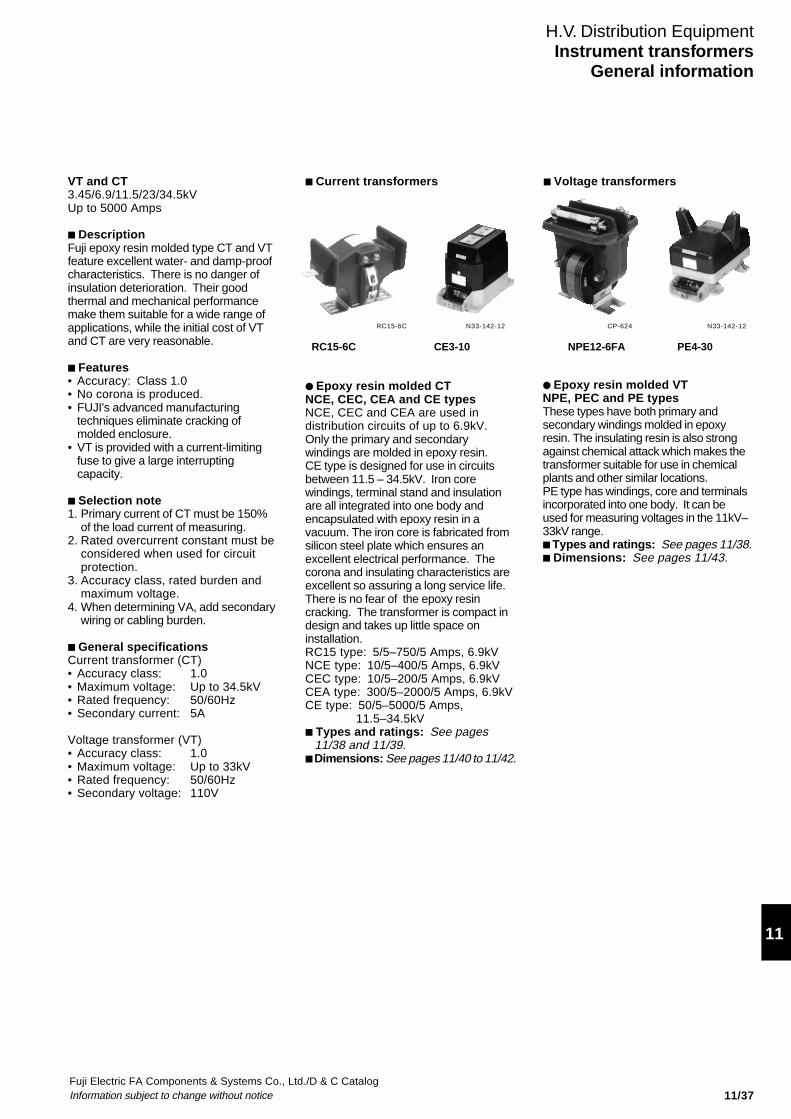
Fuji Electric FA Components & Systems Co., Ltd./D & C CatalogInformation subject to change without notice
11
11/37
Current transformers
Epoxy resin molded CTNCE, CEC, CEA and CE typesNCE, CEC and CEA are used indistribution circuits of up to 6.9kV.Only the primary and secondarywindings are molded in epoxy resin.CE type is designed for use in circuitsbetween 11.5 – 34.5kV. Iron corewindings, terminal stand and insulationare all integrated into one body andencapsulated with epoxy resin in avacuum. The iron core is fabricated fromsilicon steel plate which ensures anexcellent electrical performance. Thecorona and insulating characteristics areexcellent so assuring a long service life.There is no fear of the epoxy resincracking. The transformer is compact indesign and takes up little space oninstallation.RC15 type: 5/5–750/5 Amps, 6.9kVNCE type: 10/5–400/5 Amps, 6.9kVCEC type: 10/5–200/5 Amps, 6.9kVCEA type: 300/5–2000/5 Amps, 6.9kVCE type: 50/5–5000/5 Amps,
11.5–34.5kV Types and ratings: See pages
11/38 and 11/39. Dimensions: See pages 11/40 to 11/42.
N33-142-12 CP-624 N33-142-12
RC15-6C CE3-10 NPE12-6FA PE4-30
H.V. Distribution EquipmentInstrument transformers
General information
VT and CT3.45/6.9/11.5/23/34.5kVUp to 5000 Amps
DescriptionFuji epoxy resin molded type CT and VTfeature excellent water- and damp-proofcharacteristics. There is no danger ofinsulation deterioration. Their goodthermal and mechanical performancemake them suitable for a wide range ofapplications, while the initial cost of VTand CT are very reasonable.
Features• Accuracy: Class 1.0• No corona is produced.• FUJI's advanced manufacturing
techniques eliminate cracking ofmolded enclosure.
• VT is provided with a current-limitingfuse to give a large interruptingcapacity.
Selection note1. Primary current of CT must be 150%
of the load current of measuring.2. Rated overcurrent constant must be
considered when used for circuitprotection.
3. Accuracy class, rated burden andmaximum voltage.
4. When determining VA, add secondarywiring or cabling burden.
General specificationsCurrent transformer (CT)• Accuracy class: 1.0• Maximum voltage: Up to 34.5kV• Rated frequency: 50/60Hz• Secondary current: 5A
Voltage transformer (VT)• Accuracy class: 1.0• Maximum voltage: Up to 33kV• Rated frequency: 50/60Hz• Secondary voltage: 110V
Epoxy resin molded VTNPE, PEC and PE typesThese types have both primary andsecondary windings molded in epoxyresin. The insulating resin is also strongagainst chemical attack which makes thetransformer suitable for use in chemicalplants and other similar locations.PE type has windings, core and terminalsincorporated into one body. It can beused for measuring voltages in the 11kV–33kV range. Types and ratings: See pages 11/38. Dimensions: See pages 11/43.
Voltage transformers
RC15-6C

Fuji Electric FA Components & Systems Co., Ltd./D & C CatalogInformation subject to change without notice11/38
Selection table/CT
Maximum 3.45/6.9kV 11.5kV 23kV 34.5kVvoltage
Type RC15-6C (5–750A) CE3-10 (50–1200A) CE1-20 (50–1200A) CE4-30 (50–1200A)CE5-10 (1500–2000A) CE5-20 (1500–2000A)
NCE2-6B (10–400A) CE2-10 (1500–4000A) CE2-20 (1500–4000A)CEC1-6M (10–200A) CE6-10 (5000A) CE6-20 (5000A)CEA1-6M (300–2000A)
H.V. Distribution EquipmentInstrument transformersGeneral information
Selection table/VT
Voltage 3kV 6kV 10kV 15kV 20kV 30kVclass
Type NPE12-3FA (50VA) NPE12-6FA (50VA) PE10-10 PE10-15 PE12-20 PE4-30NPE12-3FA (100VA) NPE12-6FA (100VA) PE11-10PEC2-3FA (200VA) PEC2-6FA (200VA)
Type number nomenclature Current transformerUp to 6.9kV
CEC1-6M/100
Ordering informationCurrent transformer (CT)Specify the following:1.Type number2.Rated voltage3.Rated primary current4.Rated secondary current5.Rated frequency6.Rated burden7.Accuracy class
Voltage transformer (VT)Specify the following:1.Type number2.Rated primary voltage3.Rated secondary voltage4.Rated frequency5.Rated burden6.Accuracy class
Primary current5 to 2000A
Series nameB, C, M
Rated voltage6 : 3.45/6.9kV
Basic typeNCE2, RC15CEC1, CEA1
Voltage transformerUp to 6.6kV
NPE12-3FA/50
Rated burden50: 50VA100: 100VA200: 200VA
Rated primary voltage3: 3.3kV6: 6.6kV
Basic typeNPE12PEC1PEC2
11.5 to 34.5kV
CE3-10
11 to 33kV
PE4-10
Rated voltage10: 11.5kV20: 23kV30: 34.5kV
Basic typeCE1, CE4CE2, CE5CE3, CE6
Rated primary voltage10: 11kV15: 13.2kV20: 22kV30: 33kV
Basic typePE4, PE10PE11, PE12

Fuji Electric FA Components & Systems Co., Ltd./D & C CatalogInformation subject to change without notice
11
11/39
Types and ratingsCT 3.45/6.9kVIllustration Max. Primary/Secondary Type Withstand Mass
voltage current current(kV) (A) (kA/1s) (kg)
6.9 5/5 RC15-6C/5 0.2 4.5(3.45 10/5 RC15-6C/10 0.4 4.5common 15/5 RC15-6C/15 0.6 4.5use) 20/5 RC15-6C/20 0.8 4.5
30/5 RC15-6C/30 1.2 4.540/5 RC15-6C/40 1.6 4.5
50/5 RC15-6C/50 2 4.560/5 RC15-6C/60 2.4 4.575/5 RC15-6C/75 3 4.5100/5 RC15-6C/100 4 4.5150/5 RC15-6C/150 6 4.5
200/5 RC15-6C/200 8 4.5300/5 RC15-6C/300 12 4.5400/5 RC15-6C/400 16 4.5500/5 RC15-6C/500 20 4.5600/5 RC15-6C/600 24 4.5750/5 RC15-6C/750 30 4.5
6.9 10/5 NCE2-6B/10 0.4 7.5(3.45 15/5 NCE2-6B/15 0.6 7.5common 20/5 NCE2-6B/20 0.8 7.5use) 30/5 NCE2-6B/30 1.2 7.5
40/5 NCE2-6B/40 1.6 7.5
50/5 NCE2-6B/50 2 7.575/5 NCE2-6B/75 3 7.5100/5 NCE2-6B/100 4 7.5150/5 NCE2-6B/150 6 7.5200/5 NCE2-6B/200 8 7.5
300/5 NCE2-6B/300 12 7.5400/5 NCE2-6B/400 16 7.5
6.9 10/5 CEC1-6M/10 2.5 12(3.45 15/5 CEC1-6M/15 3.75 12common 20/5 CEC1-6M/20 5 12use) 30/5 CEC1-6M/30 7.5 12
40/5 CEC1-6M/40 10 12
50/5 CEC1-6M/50 12.5 1275/5 CEC1-6M/75 18.75 12100/5 CEC1-6M/100 25 12150/5 CEC1-6M/150 25 12200/5 CEC1-6M/200 25 12
300/5 CEA1-6M/300 25 10400/5 CEA1-6M/400 25 10500/5 CEA1-6M/500 25 10600/5 CEA1-6M/600 25 10750/5 CEA1-6M/750 25 101000/5 CEA1-6M/1000 25 101200/5 CEA1-6M/1200 25 101500/5 CEA1-6M/1500 25 102000/5 CEA1-6M/2000 25 10
SH-1045
CEC1-6M
SH-1046
CEA1-6M
H.V. Distribution EquipmentInstrument transformers
Technical information
• Rated overcurrent constant (n):n > 10 (at burden 10VA)n > 5 (at burden 20VA)
• Rated burden: 40VA
• Accuracy class: 1.0
Insulation levelWithstand voltage (AC 1min.)Primary: 22kV, Secondary: 2kVBasic-impulse insulation level: 60kV(full wave)
• Rated overcurrent constant (n):n > 10• Rated burden: 40VA
• Accuracy class: 1.0
• Insulation levelWithstand voltage (AC 1min.)Primary: 22kV, Secondary: 2kVBasic-impulse insulation level: 60kV(full wave)
• Rated overcurrent constant (n):n > 10
• Rated burden: 25VA
• Accuracy class: 1.0
• Insulation levelWithstand voltage (AC 1min.)Primary: 22kV, Secondary: 2kVBasic-impulse insulation level: 60kV(full wave)
RC15-6C
RC15-6C

Fuji Electric FA Components & Systems Co., Ltd./D & C CatalogInformation subject to change without notice11/40
H.V. Distribution EquipmentInstrument transformers
Types and ratingsVT 3300V – 33000VIllustration Primary/Secondary Rated Type Interrupting Mass Technical information
voltage burden capacity of(V) (VA) fuse (kg)
3300/110 50 NPE12-3FA/50 40kA*1 8.56600/110 50 NPE12-6FA/50 40kA*1 8.5
3300/110 100 NPE12-3FA/100 40kA*1 8.56600/110 100 NPE12-6FA/100 40kA*1 8.5
3300/110 200 PEC2-3FA/200 40kA*1 146600/110 200 PEC2-6FA/200 40kA*1 14
11000/110 200 PE11-10 40kA*3 2511000/110 200*6 PE10-10 40kA*3 38
13200/110 200*6 PE10-15 31.5kA*4 3822000/110 200 PE12-20 40kA*5 41
33000/110 200 PE4-30 – 68
Note: *1 Type PTFA-6, rated current 2A (provided with VT as standard) *2 BIL: Basic-impulse insulation level (full wave)*3 Type JR-10/5 (optional), rated current 5A *4 Type JR-10N/5 (optional), rated current 5A *5 Type JR-20/5 (optional), rated current 5A*6 400VA available
CP-624
NPE12
• Accuracy class: 1.0• Insulation level NPE12-3FA PEC2-3FA
BIL 45kV*2, 16kV AC
NPE12-6FA PEC2-6FA BIL 60kV, 22kV AC
PE11-10 PE10-10 BIL 90kV, 28kV AC
PE10-15 BIL 95kV, 34kV AC PE12-20 BIL 125kV, 50kV AC PE4-30 BIL 170kV, 70kV AC

Fuji Electric FA Components & Systems Co., Ltd./D & C CatalogInformation subject to change without notice
11
11/41
H.V. Distribution EquipmentInstrument transformers
Types and ratingsCT 11.5kV – 34.5kVIllustration Max. Primary current (A) Secondary Type Withstand Mass
voltage Single Double current current(kV) ratio ratio (A) (kA/1s) (kg)
11.5 50/5 - 5 CE3-10 25 19 to 2675/5 -100/5 200-100150/5 300-150200/5 400-200
300/5 600-300400/5 800-400500/5 1000-500600/5 1200-600
750/5 -1000/5 -1200/5 -
1500/5 - 5 CE5-10 25* 622000/5 2000-1000
1500/5 - CE2-10 50 41 to 662000/5 2000-10003000/5 3000-15004000/5 4000-2000
5000/5 5000-2500 CE6-10 50 41 to 66
23 50/5 - 5 CE1-20 25* 26 to 3575/5 -100/5 200-100150/5 300-150200/5 400-200300/5 600-300400/5 800-400500/5 1000-500600/5 1200-600750/5 -1000/5 -1200/5 -
1500/5 - 5 CE5-20 25* 622000/5 2000-1000
1500/5 - CE2-20 50 41 to 662000/5 2000-10003000/5 3000-15004000/5 4000-2000
5000/5 5000-2500 CE6-20 50 41 to 66
34.5 50/5 - 5 CE4-30 25 36 to 5075/5 -100/5 200-100150/5 300-150200/5 400-200300/5 600-300400/5 800-400500/5 1000-500600/5 1200-600750/5 -1000/5 -1200/5 -
Technical information
• Accuracy class: 1.0
• Rated overcurrent constant (n): n > 10
• Rated burden15VA (Primary current 50A)25VA (Primary current 75A)40VA (Primary current over 100A)
• Insulation levelDielectric strength: 28kV
Basic-impulse insulation level: 90kV(full wave)
• Accuracy class: 1.0
• Rated overcurrent constant (n): n >10
• Rated burden: 60VA
• Insulation level:Dielectric strength: 28kVBasic-impulse insulation level: 90kV(full wave)
• Accuracy class: 1.0• Rated overcurrent constant (n): n > 10
• Rated burden:15VA (Primary current 50A)25VA (Primary current 75A)40VA (Primary current over 100A)
• Insulation levelDielectric strength : 50kVBasic-impulse insulation level: 125kV(full wave)
• Accuracy class: 1.0• Rated overcurrent constant (n): n > 10• Rated burden: 60VA• Insulation level
Dielectric strength: 50kVBasic-impulse insulation level: 125kV(full wave)
• Accuracy class:1.0• Rated overcurrent constant (n): n > 10
• Rated burden:15VA (Primary current 50A)25VA (Primary current 75A)40VA (Primary current over 100A)
• Insulation levelDielectric level: 70kVBasic-impulse insulation level: 170kV(full wave)
N33-142-12
CE3-10
N33-142-12
CE2-10CE2-20
N33-142-12
CE1-20
N33-142-12
CE4-30
Note: * Withstand current of 25kA/2s type is also available

Fuji Electric FA Components & Systems Co., Ltd./D & C CatalogInformation subject to change without notice11/42
H.V. Distribution EquipmentInstrument transformers
Dimensions, mm/CT
CEC1-6M CEA1-6M
RC15-6C NCE2-6B
CE3-10 CE1-20
7530
30 2095
7530
30 20105
86 200 8630
50
11
20
K
ø134
L
300A-600AN.P. Primary
terminal4-ø14
1515
80
40
Secondaryterminal2-M5
150
220
ba
203.
230 t
Terminals for 1500A and 2000A ratingscannot be fitted in this direction
Primary terminal8-ø14
750-1200A
Primary terminal8-ø14
1500-2000A
k
t=6a=117b=219
t=10 a=108b=228
a=86t=15
180
111
1180
Secondaryterminal2-M5
30 302525
150
3.2 20
226
246
N.P.
50
20
200
150
K L
Primary terminal 4-M10Depth15
k
80
180
30 30
11 20
K
L
4-M10 Depth 16
14050 5010
170
7520
150180
3.2
NP
Primary terminal 150
45
Secondaryterminal2-M5
120
k
30
80ø12 80
40 2020
202 158 5
365
285
250
60155
178
15
Secondarywiring hole
Secondaryterminal box
Earthterminal M8
NP
Current transformerratio NP
K
L
M12Depth 25
K
123
155
kL
2.6
144
93D
119
190
25
A
B
2850
10
8
50
28
62 53
115
C
Secondary terminal2-M6
2-øEPrimary terminal
L
K
N. P.
1932
3656
8729
038
5
M12 Depth 25
4–ø12
Secondary wiring hole–ø14
Secondary terminal box
Earth terminal M8
60
287
15
170194
Dimensions (mm)A B C D E
5–120A 245 221 25 2 9150–200A 270 240 28 3.2 14250–750A 300 250 50 5 18
Primarycurrent (A)

Fuji Electric FA Components & Systems Co., Ltd./D & C CatalogInformation subject to change without notice
11
11/43
H.V. Distribution EquipmentInstrument transformers
CE4-30
Dimensions, mm/CT
CE5-10, CE5-20
CE2-10, CE2-20
4025
K
L
25
40 9090
370
440
100
40
20
330
60
230
190
Earthterminal
M12 Depth 25
ø12
Secondarywiring hole
Current transformerratio NP
Secondaryterminal box
Earthterminal M8
NP
k1 k2g h
N.P.
KK L
4025
40
40100
70
160
TT
TTT
365
15 4.5
4030
525
35 180230252
180
490
Standard
Primary current Thickness of conductorT
No. of primaryconductors
1500A 10 1
2000A, 2000-1000A 15 1
IECBS P1, P2 S1, S2 S1–S2–S3 1S1–1S2, 2S1-2S2
ANSI H1, H2 X1, X2 X1–X2–X3 X1–X2, Y1-Y2
Terminal symbolSecondaryPrimary
Single ratio Double ratio Double core
210
M5 Earth terminal M8
230
320
ø14
ø136
Connectionterminal M5
Connectthe lead withprimary conductor
ø14
Terminal
JEC K, L k, k1–k2– 1k–1 , 2k–2 g, h
3000A, 3000-1500A 10 3
4000A, 4000-2000A 15 3
4 – ø12
50
240
N.P. 363
15
170 330
1932 87
8756 23
041
0
36
K
L
60
M12 Depth 25
Secondary wiring hole ø14
Secondary terminal boxM8 earth terminal

Fuji Electric FA Components & Systems Co., Ltd./D & C CatalogInformation subject to change without notice11/44
Dimensions, mm/CTCE6-10CE6-20
H.V. Distribution EquipmentInstrument transformers
240
310280
hgk
Primary conductorconnection lead
Earth terminal M8
4-ø14
390 220
Connection terminal M5
ø196
195
390
585
70M5
190150 130
280
35
K
25
354012
Name plate
K L

Fuji Electric FA Components & Systems Co., Ltd./D & C CatalogInformation subject to change without notice
11
11/45
H.V. Distribution EquipmentInstrument transformers
PE10-10PE10-15
Dimensions, mm/VT (with fuse links)
PE11-10
NPE12-3FANPE12-6FA
PEC2-3FAPEC2-6FA
PE12-20 PE4-30
190
120NP
50
11011
2024
5
120
3.2
u
50
v20
180
40
Primary terminal 2-M6
U V
6522
Secondaryterminal2-M5NP
Secondaryterminal2-M4
vu
120150
215
3.2
170 15080
6511
uv
Primary terminal 2-M6
U V
300250
Mountinghole 4-M12
Secondary wiring hole ø14
Earth terminal M8
Secondaryterminal box
N.P.
205260
370
320 90
427
13
N. P.
U V
u v
35
20
6
Sec.terminal M6
4-ø12
ø10
305 295220 135 160
240115 125
230200
220190
390
9529
5
134
3
N. P.U V
6
u v
Sec.terminal Mark
305 360220 135 225
220250 125 135
260
200
395
9530
0
140
4.5
35
20
ø10
16
1
R6
12200
220Setting dimension
N. P.
U V
6
u v
35
16
1
R6
20
12200
220
M6
Setting dimension
ø10
290 160 315
250 265
220 128 137200
372 475
480
9538
5
147
4.5

Fuji Electric FA Components & Systems Co., Ltd./D & C CatalogInformation subject to change without notice11/46
H.V. Distribution EquipmentInstrument transformersZCT, EVT and special purpose CT
DescriptionFUJI can supply special purpose CTs,ZCTs (Zero-phase currenttransformers) and EVTs (Earthingvoltage transformers) as well asstandard FUJI instrument transformers.Some of the versions are describedbelow.
CED and ZCEDThe CED and ZCED are split-construction types.They can bemounted in position withoutdisconnecting the cables.CED: Epoxy-molded split-toroidal type CTZCED: Epoxy-molded split-toroidal type
ZCT
ZCEZCE type is toroidal-type ZCTs andmolded in epoxy resin.
GVE and GPEGVE and GPE series are 3-phaseearthing voltage transformers.GVE: Epoxy-molded type (3.3kV,6.6kV)GPE: Epoxy-molded type (11 to 33kV)
Note: All types are for indoor use only.
Type number nomenclature• Toroidal type ZCT
ZCE A/
Basic typeZCE: Epoxy molded toroidal typeZCED: Epoxy molded
split-toroidal type
Hole diameter, mm1: 65 4: 125 (ZCE type)2: 80 (ZCE type) 130 (ZCED type)
90 (ZCED type) 5: 190 (ZCE type)3: 100 150 (ZCED type)
Rated primary current (Amps.): 200 to 1500
• Split-toroidal type CTCED /
Basic typeHole diameter, mm1: 652: 903, 3A, 3B: 1004: 130Rated primary current (Amps)200 to 3000
• Earthing voltage transformer EVTGPE - F -
Basic typeGVE, GPE: Epoxy-molded type
Secondary rated burdenGVE GPE:1: 3 x 100VA 21: 3 x 200VA2: 3 x 200VA 13: 3 x 200VA
12: 3 x 200VA9: 3 x 200VA8: 3 x 200VA7: 3 x 200VA(400A)
Rated primary voltage3: 3.3kV 10: 11kV 20: 22kV6: 6.6kV 15: 13.2kV 30: 33kVRated secondary voltage
Toroidal type ZCTZCE2A
Split-toroidaltype CTCED2
CP-622
CP-620
Earthing voltagetransformerGVE1
CP-619
Toroidal type ZCTDescription Hole Primary Rated zero-phase Rated Overcurrent Type
diameter current current (mA) burden constant(mm) (A) Primary Secondary (Ω) (n0)
Indoor use 65 0–200 200 1.5 10 n0 > 2000 ZCE1A/20080 0–400 ZCE2A/400
Epoxy molded 100 0–750 ZCE3A/750toroidal type 125 0–1200 ZCE4A/1200
190 0–3000 ZCE5A/3000
Indoor use 65 0–200 200 1.5 10 n0 > 2000 ZCED1/20090 0–400 ZCED2/400
Epoxy molded 100 0–600 ZCED3/600split-toroidal 130 0–750 ZCED4/750type 150 0–1500 ZCED5/1500
( ) Available on request

Fuji Electric FA Components & Systems Co., Ltd./D & C CatalogInformation subject to change without notice
11
11/47
H.V. Distribution EquipmentInstrument transformers
Split-toroidal type CTHole diameter Primary current (A) Secondary Rated Overcurrent Type(mm) Single ratio Double ratio current (A) burden (VA) constant (n)
65 200 – 5 15 n > 10 CED1/200300 – 15 CED1/300400 – 25 CED1/400500 – 25 CED1/500600 – 40 CED1/600750 – 40 CED1/750
90 200 – 5 15 n > 10 CED2/200300 – 25 CED2/300400 – 40 CED2/400500 – 40 CED2/500600 – 40 CED2/600750 – 40 CED2/750
1000 – 5 40 n > 20 CED2/10001200 – 40 CED2/12001500 – 40 CED2/1500
100 300 – 5 25 n > 10 CED3/300400 – 40 CED3/400500 – 40 CED3/500600 – 40 CED3/600
750 – 5 40 n > 20 CED3/7501000 – 40 CED3/10001200 – 40 CED3/12001500 – 40 CED3/15002000 – 40 CED3/20003000 – 40 CED3/3000
300 300–150 5 25 n > 20 CED3A/300400 400–200 40 CED3A/400500 – 40 CED3A/500600 600–300 40 CED3A/600
300 300–150 5 40 n > 20 CED3B/300
130 400 400–200 5 40 n >10 CED4/400500 – 40 CED4/500600 600–300 40 CED4/600
750 – 5 40 n > 20 CED4/750– 800–400 40 CED4/800
1000 1000–500 40 CED4/10001200 1200–600 40 CED4/12001500 1500–750 40 CED4/15002000 2000–1000 40 CED4/20003000 3000–1500 40 CED4/3000

Fuji Electric FA Components & Systems Co., Ltd./D & C CatalogInformation subject to change without notice11/48
H.V. Distribution EquipmentInstrument transformers
Earthing voltage transformer EVTRated voltage (V) Rated burden (VA) Dielectric strength Impulse*1 Type Fuse
(kV, 1minute) (kV)Primary Secondary Tertiary Secondary Tertiary Primary Secondary
3300 110 110 3 × 100 3 × 500 2 2 45 GVE1-3FA-110/5G PTFA-6*2
3 3 × 200 3 × 500 2 2 45 GVE2-3FA-110/5G
6600 110 110 3 × 100 3 × 500 2 2 60 GVE1-6FA-110/5G3 3 × 200 3 × 500 2 2 60 GVE2-6FA-110/5G
11000 110 110 3 × 200 3 × 200 2 2 90 GPE9-10 JR-10/5*3
3 3 × 200 3 × 200 2 2 75 GPE8-10 JR-10/5*3
3 × 200 3 × 200 2 2 90 GPE7-10 JR-10/5*3
13200 110 110 3 × 200 3 × 200 2 2 95 GPE7-15 JR-10N/5*3
3
22000 110 110 3 × 200 3 × 200 2 2 125 GPE12-20 JR-20/5*3
322000 110 110 3 × 200 3 × 200 2 2 150 GPE13-20 JR-20/5*3
333000 110 110 3 × 200 3 × 200 2 2 170 GPE21-30 –
3
ZCE5A/3000
Dimensions, mm Toroidal-type ZCTZCE1A, 2A, 3A,4A
Type d X Y Z H W A B Mass(kg)
ZCE1A/200 65 140 75 180 110 90 40 25 4.0ZCE2A/400 80 160 90 210 130 90 40 25 5.6ZCE3A/750 100 185 105 248 155 120 60 35 8.4ZCE4A/1200 125 214 120 287 180 120 60 35 12.0
Dimensions for reference only. Please confirm before construction begins.
Note: *1: 1.2 × 50µs *2: Provided *3: Optional
K
X
ZH
WA
2010
3.220
B
Test terminal 2-M5
Secondaryterminal 2-M5
NP Y
1351752-ø15
L
ød
k
kt lt
ø310
K
355
180
200
ø190
Test terminal M5
Secondaryterminal M5
160200
25
40
25
100L
2-ø15
3.2
kkt Lt
Mass: 14kg

Fuji Electric FA Components & Systems Co., Ltd./D & C CatalogInformation subject to change without notice 11/49
11
Dimensions, mm Split-toroidal type CT/ZCED
Earth voltage transformer VT/GVE1, GVE2
Type X Y Z a b c d e f g h i j k m n Mass(kg)
ZCED1 260 95 225 100 125 130 65 27 30 135 175 2 14 M10 3.2 27 15ZCED2 310 110 270 120 150 150 90 27 40 135 175 2 14 M10 4.5 27 20ZCED3 340 110 295 130 165 150 100 30 40 135 175 2 14 M10 4.5 27 25ZCED4 380 140 350 155 195 200 130 30 55 200 250 4 18 M10 6 30 30ZCED5 460 150 405 185 220 200 150 30 55 200 250 4 18 M12 6 30 52
Dimensions for reference only. Please confirm before construction begins.
Type X Y Z d a1 a2 b1 b2 c E F n
CED1 95 260 225 65 260 80 220 — 125 27 57 2CED2 110 310 285 90 300 90 260 — 165 27 82 2CED3 110 340 295 100 300 95 260 — 165 27 67 2CED3A 200 340 295 100 300 190 260 120 165 50 65 4CED3B 250 340 295 100 300 240 260 120 165 50 65 4CED4 125 350 305 130 300 110 260 70 165 50 50 4
Dimensions for reference only. Please confirm before construction begins.
Split-toroidal type CT/CED
Secondaryterminal M5 Tertiary
terminalM5
Primaryneutralterminal M6
b b
uv
abv
uv
abv
uv
abv
FusePrimaryterminal M6
4-ø12f
f+40
Y
U U U
(U) (V) (W)
NP (3-phase)
NP (single-phase)
a
U (U)
U V
U (V)
U V
U (W)
U V
u v w a b c f
0
0
u v a b u v a b u v a b
c d
ze
c
X
X
K
4-k
L
C
ef
aZ
b
ZCED4,5 Mounting hole
Secondary terminal 2-M5
Test terminal 2-M5
100
ød
gh
m
i-øj
NPY
kkt Lt
n
110
NP
ø
4-M10
Y
d
K
CZ
3.2
b1a1
Secondaryterminal M5
NP
Mountinghole n-ø14
k l
L
X
b2a2
E F
Type X Y Z a b c d e f Mass(kg)
GVE1 428 265 284 136 146 104 220 90 220 59GVE2 476 305 300 152 162 128 220 100 220 82
Dimensions for reference only. Please confirm before construction begins.

Fuji Electric FA Components & Systems Co., Ltd./D & C CatalogInformation subject to change without notice11/50
Dimensions, mm
H.V. Distribution EquipmentInstrument transformers
GPE12-20 Earthing voltage transformer VT (with fuse links)GPE9-10
GPE7-10, GPE7-15
GPE8-10 GPE13-20
GPE21-30
Mass: 160kg
Earth terminal M8
Primary neutral terminal M6
85 ø10
4-ø12220
35
20
301
95
416
203
Name plate
3 phase name plate
452226 226
566
160
295
135 160
160
134
260
6
4014
3
153
126
V VV
v
u
v
u
u u u
a
b v
u a
b v
u a
b
u a
v b
V
u a
v b
V
u
U U U
a
v b
V
320
467
50 6
320
260
350
20
900
350
310560
Secondary and tertiaryterminal M6
Neutral terminal M8
2-M8, Depth 15 Lifting lug
ø14
160
U
u
v
a
b
u
v
a
b
u
v
a
b
U U U
V V
V
V W
170
160135
290
Primary neutralterminal M6
Fuse
170
35ø10
500
260
252
160
4604-ø12
M6
220
262
95203
20
40
6
377
35
410
a
b
u
v
a
b
u
v
a
b
u
v
770
Lifting lug
300
3504-ø14
455
475
315
275275
773UUU
223 140
2098
66
25
183
385
5095
530 M6
M8
ø10
226 226
35
452
680
310
350
360
377
135 225
4-ø14
280
95
20
a
b
u
v
a
b
u
v
a
b
u
U U U
v
V V V
50
425
6
ø10
Fuse
Secondary andtertiary terminalM6
Primary neutralterminalM86
3016
3
Mass: 125kg
Mass: 140kg
Mass: 76kg
Mass: 75kg
U
UU
UU
U
ab
uv
uv
uv
V
ab
V
ab
V
ø10
901 535
320
560 310
350
510
95
6
6
415
195
148
25504-ø14
320 225
160
310
261
75 35
20
M8
Earth terminal M8
Lifting lug
Mass: 190kg

Catalog DisclaimerThe information contained in this catalog does not constitute an express or implied warranty of quality, any warranty of merchantability of fitness for a particular purpose is hereby disclaimed.
Since the user's product information, specific use application, and conditions of use are all outside of Fuji Electric FA Components & Systems'control, it shall be the responsibility of the user to determine the suitability of any of the products mentioned for the user's application.
One Year Limited WarrantyThe products identified in this catalog shall be sold pursuant to the terms and conditions identified in the"Conditions of Sale" issued by Fuji Electric FA with each order confirmation.
Except to the extent otherwise provided for in the Conditions of Sale issued by Fuji Electric FA, Fuji Electric FA warrants that the Fuji Electric FA products identified in this catalog shall be free from significant defects in materials and workmanship provided the product has not been: 1) repaired or altered by others than Fuji Electric FA; 2) subjected to negligence, accident, misuse, or damage by circumstances beyond Fuji Electric FA's control; 3) improperly operated, maintained or stored; or 4) used in other than normal use or service. This warranty shall apply only to defects appearing within one (1) year from the date of shipment by Fuji Electric FA, and in such case, only if such defects are reported to Fuji Electric FA within thirty (30) days of discovery by purchaser. Such notice should be submitted in writing to Fuji Electric FA at 5-7, Nihonbashi Odemma-cho, Chuo-ku, Tokyo, Japan. The sole and exclusive remedy with respected to the above warranty whether such claim is based on warranty, contract, negligence, strict liability or any other theory, is limited to the repair or replacement of such product or, at Fuji Electric FA's option reimbursement by Fuji Electric FA of the purchase price paid to Fuji Electric FA for the particular product. Fuji Electric FA does not make any other representations or warranties, whether oral or in writing, expressed or implied, including but not limited to any warranty regarding merchantability or fitness for a particular purpose. Except as provided in the Conditions of Sale, no agent or representative of Fuji Electric FA is authorized to modify the terms of this warranty in writing or orally. In no event shall Fuji Electric FA be liable for special, indirect or consequential damages, including but not limited to, loss of use of the product, other equipment, plant and power system which is installed with the product, loss of profits or revenues, cost of capital, or claims against the purchaser or user of the product by its customers resulting from the use of information, recommendations and descriptions contained herein. The purchaser agrees to pass on to its customers and users, in writing at the time inquiries and orders are received by buyer, Fuji Electric FA's warranty as set forth above.
Caution "Safety precautions"• Operate (keep) in the environment specified in the operating instructions and manual. High temperature, high
humidity, condensation, dust, corrosive gases, oil, organic solvents, excessive vibration or shock might cause electric shock, fire, erratic operation or failure.
• Follow the regulations of industrial wastes when the product is to be discarded.• The products covered in this catalogs have not been designed or manufactured for use in equipment or systems
which, in the event of failure, can lead to loss of human life.• If you intend to use the products covered in this catalog for special applications, such as for nuclear energy control,
aerospace, medical, or transportation, please consult our Fuji Electric FA agent.• Be sure to provide protective measures when using the product covered in these catalogs in equipment which, in the
event of failure, may lead to loss of human life or other grave results.• Follow the directions of the operating instructions when mounting the product.

Information in this catalog is subject to change without notice.
5-7, Nihonbashi Odemma-cho, Chuo-ku, Tokyo, 103-0011, Japan URL http://www.fujielectric.co.jp/fcs/eng
IND
IVID
UA
L CA
TA
LOG
from
D&
C C
AT
ALO
G 20th E
ditio
n
11
LOW VOLTAGE PRODUCTS Up to 600 VoltsIndividualcatalog No.
01 Magnetic Contactors and StartersThermal Overload Relays, Solid-state Contactors
02
Industrial Relays, Industrial Control RelaysAnnunciator Relay Unit, Time Delay Relays
Manual Motor Starters and Contactors Combination Starters
Pushbuttons, Selector Switches, Pilot LightsRotary Switches, Cam Type Selector SwitchesPanel Switches, Terminal Blocks, Testing Terminals
Molded Case Circuit BreakersAir Circuit Breakers
Earth Leakage Circuit BreakersEarth Leakage Protective Relays
Measuring Instruments, Arresters, TransducersPower Factor ControllersPower Monitoring Equipment (F-MPC)
Circuit ProtectorsLow Voltage Current-Limiting Fuses
03
04
05
06
07
08
09
10
HIGH VOLTAGE PRODUCTS Up to 36kV
11Disconnecting Switches, Power FusesAir Load Break SwitchesInstrument Transformers — VT, CT
D&C CATALOG DIGEST INDEX
AC Power RegulatorsNoise Suppression FiltersControl Power Transformers
12 Vacuum Circuit Breakers, Vacuum Magnetic ContactorsProtective Relays
Limit Switches, Proximity SwitchesPhotoelectric Switches
01 02 03 04 05 06 07 08 09 10 11 12
HIGHVOLTAGE
EQUIPMENTUp to 36kV
INDIVIDUAL CATALOGfrom D&C CATALOG 20th Edition 11INDIVIDUAL CATALOG
from D&C CATALOG 20th Edition 11
DISCONNECTING SWITCHES
INSTRUMENT TRANSFORMERS — VT, CT
AIR LOAD BRESK SWITCHES
POWER FUSES
Power fusesHF type
Power fusesSCF and HF types
Air load break switchesLB, LBS and RF types
Air load break switchesLB, LBS and RF types
Instrument transformersCT
Instrument transformersVT
Disconnecting switchesV3 type
Disconnecting switchesV3 type
Instrument transformersZCT
2010-09 PDF FOLS DEC2011
