1.1 safety - image.btone-mro.comimage.btone-mro.com/siteupload/vlt2800快速指南.pdf · title...
TRANSCRIPT
1 Quick Guide
1.1 Safety1.1.1 Warnings
High Voltage Warning:The voltage of the frequency converter is dangerous whenever it is connected tomains. Incorrect installation of the motor or frequency converter may cause damageto the equipment, serious injury or death. Consequently, it is essential to complywith the instructions in this manual as well as local and national rules and safetyregulations.
Warning:Touching the electrical parts may be fatal - even after the equipment has been dis-connected from mains.Also make sure that other voltage inputs have been discon-nected (linkage of DC intermediate circuit). Be aware that there may be high voltageon the DC link even when the LEDs are turned off. Before touching any potentiallylive parts of the frequency converter, wait at least 4 minutes.
Leakage Current:The earth leakage current from the frequency converter exceeds 3.5 mA. Accordingto IEC 61800-5-1 a reinforced Protective Earth connection must be ensured bymeans of a min. 10mm² Cu or an addtional PE wire - with the same cable crosssection as the Mains wiring - must be terminated separately.To increase safety, install an RCDResidual Current Device:This product can cause a DC current in the protective conductor. Where a residualcurrent device (RCD) is used for extra protection, only an RCD of Type B (time de-layed) shall be used on the supply side of this product. See also Danfoss ApplicationNote on RCD, MN.90.GX.YY.Protective earthing of the frequency converter and the use of RCDs must alwaysfollow national and local regulations.
Motor Thermal Protection:Protection against Motor overload is not included in the factory setting. If this func-tion is required, set par. 128 Motor Thermal Protection to data value ETR trip or datavalue ETR warning. For the North American market: The ETR functions provideoverload protection of the motor, class 20, in accordance with NEC.
Installation in high altitudes:For altitudes above 2 km, please contact Danfoss regarding PELV.
VLT 2800 Quick Guide 1 Quick Guide
MG.28.M1.02 - VLT® is a registered Danfoss trademark 1
1
1.1.2 Safety Instructions
• The frequency converter must be disconnected from the mains if repair work is to becarried out. Check that the mains supply has been disconnected and the prescribed timehas passed before removing motor and mains plugs.
• Make sure the frequency converter is properly connected to earth.
• Protect users against supply voltage.
• Protect the motor against overloading according to national and local regulations.
• The earth leakage current exceeds 3.5 mA. For ELCB types, please see application noteMN.90.GX.YY.
• The [STOP/RESET] key on the control panel of the frequency converter does not dis-connect the equipment from mains and is thus not to be used as a safety switch.
• Note that the frequency converter has more voltage inputs than L1, L2 and L3 when DCbus terminals are used. Check that all voltage inputs are disconnected and that the pre-scribed time has passed before repair work is commenced.
1.1.3 Warning against unintended start
1. The motor can be brought to a stop by means of digital commands, bus commands,references or a local stop, while the frequency converter is connected to mains. If per-sonal safety considerations make it necessary to ensure that no unintended start oc-curs, these stop functions are not sufficient.
2. While parameters are being changed, the motor may start. Consequently, the stop key[STOP/RESET] must always be activated, following which data can be modified.
3. A motor that has been stopped may start if faults occur in the electronics of the frequencyconverter, or if a temporary overload or a fault in the supply mains or the motor con-nection ceases.
1.1.4 Use on Isolated Mains
See section RFI Switch in the operating instructions regarding use on isolated mains.
It is important to follow the recommendations regarding installation on IT-mains, since sufficientprotection of the complete installation must be observed. Not taking care using relevant moni-toring devices for IT-mains may result in damage.
1 Quick Guide VLT 2800 Quick Guide
2 MG.28.M1.02 - VLT® is a registered Danfoss trademark
1

1.2 IntroductionUse this Quick Guide to carry out quick andEMC-correct installation of the frequency con-verter in five steps.
Read the safety section beforeinstalling the unit.
NB!The Operating Instructions, MG.27.AX.YY, give further examplesof installation and describe allfunctions in detail.The Design Guide, MG.27.EX.YY, contains extensive in-formation.
1.2.1 Abbreviations
ELCB Earth Leakage Circuit BreakersNO Normally openNC Normally closedPD2 Dual phase (for 2822, 2840 that only run 3-phase as standard D2), 220 - 240 VRCD Residual Current Device
1.2.2 Available Litterature
NB!This quick guide contains only the very basic information necessary for installing andrunning the drive.For more information please consult the VLT 2800 Design Guide, MG.27.EX.YY
VLT 2800 Quick Guide 1 Quick Guide
MG.28.M1.02 - VLT® is a registered Danfoss trademark 3
1

Title Literature no.VLT 2800 Operating Instructions MG.27.AX.YYVLT 2800 Design Guide MG.27.EX.YYVLT 2800 Data Sheet MD.27.AX.YYMounting Instruction for VLT 2800 MI.28.AX.YYVLT 2800 Filter Instruction MI.28.BX.YYPrecise Stop MI.28.CX.YYCold Plate MI.28.DX.YYVLT 2800 NEMA 1 Terminal Covering MI.28.EX.YYVLT 2800 DeviceNet Cable MI.28.FX.YYVLT 2800 Blue Star Condensing Unit MI.28.GX.YYVLT 2880 - 2882 Spare Part Instruction MI.28.HX.YYWobble Function MI.28.JX.YYVLT 2800 LCP Remote-mounting Kit MI.56.AX.YYUser Instruction for LOP MI.90.EX.YYBrake Resistor MI.90.FX.YYProfibus DP Manual MG.90.AX.YYVLT 2800 DeviceNet Manual MG.90.BX.YYMetasys N2 Manual MG.90.CX.YYProfibus Manual MG.90.EX.YYOutput Filter Manual MG.90.NX.YYBrake Resistor Manual MG.90.OX.YYMCT-10 Manual MG.10.RX.YYModbus RTU Manual MG.10.SX.YYProtection against Electrical Hazards MN.90.GX.YY
X = Revision Number, Y = Language code
Application notes can be found on http://www.danfoss.com/BusinessAreas/DrivesSolutions/Doc-umentations/Technical+Documentation.htm
1.2.3 Approvals
1.2.4 Disposal Instruction
Equipment containing electrical components must not be disposed oftogether with domestic waste.It must be separately collected with electrical and electronic wasteaccording to local and currently valid legislation.
1.3 Mechanical InstallationVLT 2800 frequency converters allow side-by-side installation on a wall in any position as the unitsdo not require ventilation on the side. Because of the need for cooling, there must be 10 cm freeair passage above and below the frequency converter.
All units with enclosure IP 20 must be integrated in cabinets and panels. IP 20 is not suitable forremote mounting. In some countries, e.g. in the USA, units with enclosure NEMA 1 are approvedfor remote mounting.
1 Quick Guide VLT 2800 Quick Guide
4 MG.28.M1.02 - VLT® is a registered Danfoss trademark
1
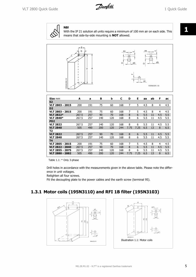
NB!With the IP 21 solution all units require a minimum of 100 mm air on each side. Thismeans that side-by-side mounting is NOT allowed.
Size mm A a B b C D E øa øb F øcS2VLT 2803 - 2815 200 191 75 60 168 7 5 4.5 8 4 4.5D2VLT 2803 - 2815 200 191 75 60 168 7 5 4.5 8 4 4.5VLT 2822* 267.5 257 90 70 168 8 6 5.5 11 4.5 5.5VLT 2840* 267.5 257 140 120 168 8 6 5.5 11 4.5 5.5PD2VLT 2822 267.5 257 140 120 168 8 6 5.5 11 4.5 5.5VLT 2840 505 490 200 120 244 7.75 7.25 6.5 13 8 6.5T2VLT 2822 267.5 257 90 70 168 8 6 5.5 11 4.5 5.5VLT 2840 267.5 257 140 120 168 8 6 5.5 11 4.5 5.5T4VLT 2805 - 2815 200 191 75 60 168 7 5 4.5 8 4 4.5VLT 2822 - 2840 267.5 257 90 70 168 8 6 5.5 11 4.5 5.5VLT 2855 - 2875 267.5 257 140 120 168 8 6 5.5 11 4.5 5.5VLT 2880 - 2882 505 490 200 120 244 7.75 7.25 6.5 13 8 6.5
Table 1.1: * Only 3-phase
Drill holes in accordance with the measurements given in the above table. Please note the differ-ence in unit voltages.Retighten all four screws.Fit the decoupling plate to the power cables and the earth screw (terminal 95).
1.3.1 Motor coils (195N3110) and RFI 1B filter (195N3103)
Illustration 1.1: Motor coils
VLT 2800 Quick Guide 1 Quick Guide
MG.28.M1.02 - VLT® is a registered Danfoss trademark 5
1

1.3.2 Terminal cover
The drawing below gives the dimensions for NEMA 1 terminal covers for VLT 2803-2875.Dimension 'a' depends on the unit type.
1.3.3 IP 21 solution
Type Code number A B CVLT 2803-2815 200-240 V,VLT 2805-2815 380-480 V
195N2118 47 80 170
VLT 2822 200-240 V,VLT 2822-2840 380-480 V
195N2119 47 95 170
VLT 2840 200-240 V,VLT 2822 PD2, TR1 2855-2875380-480 V
195N2120 47 145 170
TR1 2880-2882 380-480 V,VLT 2840 PD2
195N2126 47 205 245
Table 1.2: Dimensions
1 Quick Guide VLT 2800 Quick Guide
6 MG.28.M1.02 - VLT® is a registered Danfoss trademark
1
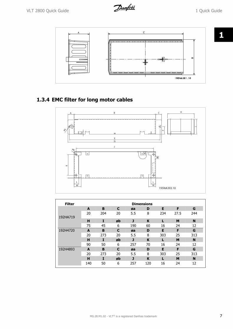
1.3.4 EMC filter for long motor cables
Filter Dimensions
192HA719
A B C øa D E F G20 204 20 5.5 8 234 27.5 244
H I øb J K L M N75 45 6 190 60 16 24 12
192H4720 A B C øa D E F G20 273 20 5.5 8 303 25 313H I øb J K L M N90 50 6 257 70 16 24 12
192H4893 A B C øa D E F G20 273 20 5.5 8 303 25 313H I øb J K L M N
140 50 6 257 120 16 24 12
VLT 2800 Quick Guide 1 Quick Guide
MG.28.M1.02 - VLT® is a registered Danfoss trademark 7
1

1.4 Electrical Installation1.4.1 Electrical Installation in General
NB!All cabling must comply with national and local regulations on cable cross-sectionsand ambient temperature. Copper conductors required, (60-75° C) recommended.
Details of terminal tightening torques.
VLT Terminals Torque (Nm) Torque, Control Cables (Nm)
2803 - 2875 Power mains brake 0.5 - 0.6
0.22 - 0.25Earth 2 - 32880 - 2882,2840 PD2
Power mains brake 1.2 - 1.5Earth 2 - 3
Table 1.3: Tightening of terminals.
1.4.2 Power Cables
NB!Please note that the power terminals can be removed.
Connect mains to the mains terminals of the frequency converter, i.e. L1, L2 and L3 and the earthconnection to terminal 95.
VLT 2803 - VLT 2815 VLT 2822 - VLT 2840
1 Quick Guide VLT 2800 Quick Guide
8 MG.28.M1.02 - VLT® is a registered Danfoss trademark
1
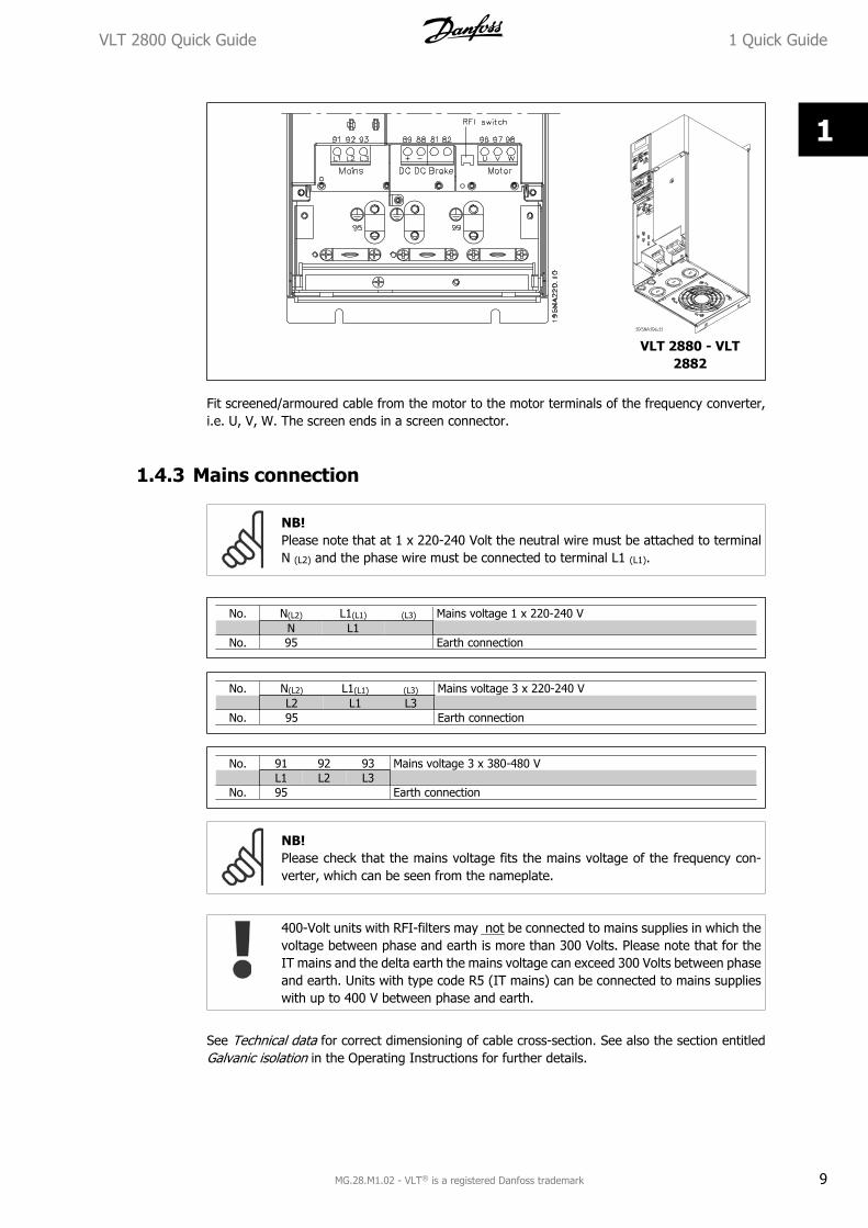
VLT 2880 - VLT2882
Fit screened/armoured cable from the motor to the motor terminals of the frequency converter,i.e. U, V, W. The screen ends in a screen connector.
1.4.3 Mains connection
NB!Please note that at 1 x 220-240 Volt the neutral wire must be attached to terminalN (L2) and the phase wire must be connected to terminal L1 (L1).
No. N(L2) L1(L1) (L3) Mains voltage 1 x 220-240 V N L1
No. 95 Earth connection
No. N(L2) L1(L1) (L3) Mains voltage 3 x 220-240 V L2 L1 L3
No. 95 Earth connection
No. 91 92 93 Mains voltage 3 x 380-480 V L1 L2 L3
No. 95 Earth connection
NB!Please check that the mains voltage fits the mains voltage of the frequency con-verter, which can be seen from the nameplate.
400-Volt units with RFI-filters may not be connected to mains supplies in which thevoltage between phase and earth is more than 300 Volts. Please note that for theIT mains and the delta earth the mains voltage can exceed 300 Volts between phaseand earth. Units with type code R5 (IT mains) can be connected to mains supplieswith up to 400 V between phase and earth.
See Technical data for correct dimensioning of cable cross-section. See also the section entitledGalvanic isolation in the Operating Instructions for further details.
VLT 2800 Quick Guide 1 Quick Guide
MG.28.M1.02 - VLT® is a registered Danfoss trademark 9
1

1.4.4 Motor connection
Connect the motor to terminals 96, 97, 98. Connect earth to terminal 99.See Technical data for correct dimensioning of cable cross-section.
All types of three-phase asynchronous standard motors can be connected to a frequency con-verter. Normally, small motors are star-connected (230/400 V, Δ/ Y).
NB!In motors without phase insulation paper, an LC filter should be fitted on the outputof the frequency converter.
The factory setting is for clockwise rotation.The direction of rotation can be changed by switching two phases on the motor terminals.
1.4.5 Parallel connection of motors
The frequency converter is able to control several motors connected in parallel.Please consult the Operating Instructions for further information.
NB!Be aware that the total cable length, listed in the section EMC Emission.
NB!Parameter 107 Automatic motor adaption, AMT cannot be used when motors areconnected in parallel. Parameter 101 Torque characteristic must be set to Specialmotor characteristics [8] when motors are connected in parallel.
1 Quick Guide VLT 2800 Quick Guide
10 MG.28.M1.02 - VLT® is a registered Danfoss trademark
1
1.4.6 Motor Cables
See General Specifications for correct dimensioning of motor cable cross-section and length. SeeEMC Emissions for relationship between length and EMC emission.Always comply with national and local regulations on cable cross-section.
NB!If an unscreened/unarmoured cable is used, some EMC requirements are not com-plied with, see EMC test results in the Design Guide.
If the EMC specifications regarding emission are to be complied with, the motor cable must bescreened/armoured, unless otherwise stated for the RFI filter in question. It is important to keepthe motor cable as short as possible so as to reduce the noise level and leakage currents to aminimum. The motor cable screen must be connected to the metal cabinet of the frequency con-verter and to the metal cabinet of the motor. The screen connections are to be made with thebiggest possible surface area (cable clamp). This is enabled by different installation devices indifferent frequency converters. Mounting with twisted screen ends (pigtails) is to be avoided, sincethese spoil the screening effect at high frequencies. If it is necessary to break the screen to installa motor isolator or motor relay, the screen must be continued at the lowest possible HF impedance.
1.4.7 Motor Thermal Protection
The electronic thermal relay in UL-approved frequency converters has received the UL-approvalfor single motor protection, when parameter 128 Motor thermal protection has been set for ETRTrip and parameter 105 Motor current, IM, N has been programmed to the rated motor current(see motor nameplate).
1.4.8 Control Cables
Remove the front cover underneath the control panel. Place a jumper between terminals 12 and27.
Control cables must be screened/armoured. The screen must be connected to the frequency con-verter chassis by means of a clamp. Normally, the screen must also be connected to the chassisof the controlling unit (use the instructions for the unit in question). In connection with very longcontrol cables and analogue signals, in rare cases depending on the installation, 50/60 Hz earthloops may occur because of noise transmitted from mains supply cables. In this connection, it maybe necessary to break the screen and possibly insert a 100 nF capacitor between the screen andthe chassis.
See section entitled Earthing of screened/armoured control cables in the VLT 2800 Design Guidefor the correct termination of control cables.
VLT 2800 Quick Guide 1 Quick Guide
MG.28.M1.02 - VLT® is a registered Danfoss trademark 11
1
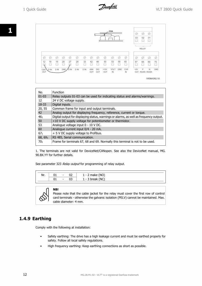
No. Function01-03 Relay outputs 01-03 can be used for indicating status and alarms/warnings.12 24 V DC voltage supply.18-33 Digital inputs.20, 55 Common frame for input and output terminals.42 Analog output for displaying frequency, reference, current or torque.461 Digital output for displaying status, warnings or alarms, as well as frequency output.50 +10 V DC supply voltage for potentiometer or thermistor.53 Analogue voltage input 0 - 10 V DC.60 Analogue current input 0/4 - 20 mA.671 + 5 V DC supply voltage to Profibus.68, 691 RS 485, Serial communication.701 Frame for terminals 67, 68 and 69. Normally this terminal is not to be used.
1. The terminals are not valid for DeviceNet/CANopen. See also the DeviceNet manual, MG.90.BX.YY for further details.
See parameter 323 Relay output for programming of relay output.
Nr. 01 - 02 1 - 2 make (NO) 01 - 03 1 - 3 break (NC)
NB!Please note that the cable jacket for the relay must cover the first row of controlcard terminals - otherwise the galvanic isolation (PELV) cannot be maintained. Max.cable diameter: 4 mm.
1.4.9 Earthing
Comply with the following at installation:
• Safety earthing: The drive has a high leakage current and must be earthed properly forsafety. Follow all local safety regulations.
• High frequency earthing: Keep earthing connections as short as possible.
1 Quick Guide VLT 2800 Quick Guide
12 MG.28.M1.02 - VLT® is a registered Danfoss trademark
1
Connect all earthing systems to ensure the lowest possible conductor impedance. The lowestpossible conductor impedance is achieved by keeping the conductor as short as possible and bygrounding with the greatest possible surface area. If multiple drives are installed in a cabinet, thecabinet backplate, which must be made of metal, should be used as a joint earth reference plate.The drives must be fitted to the backplate at the lowest possible impedance.
To achieve low impedance, connect the drive to the backplate with the drive fastening bolts. Thebackplate must be completely free from paint.
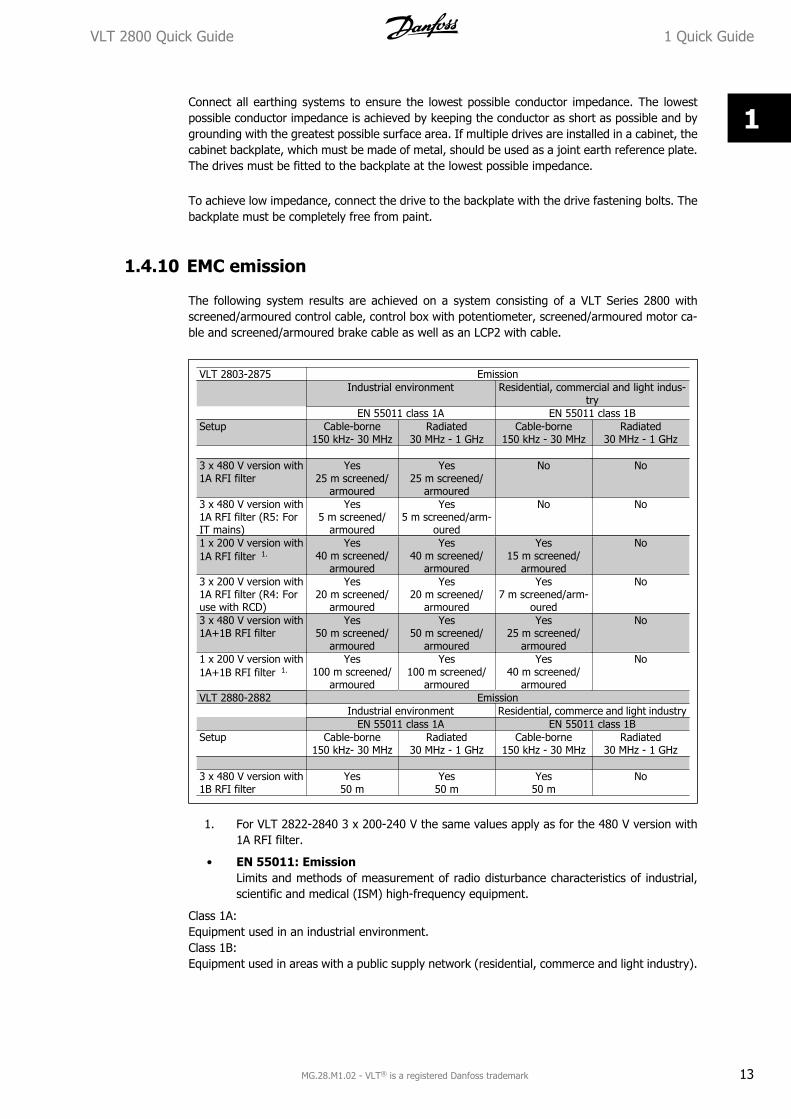
1.4.10 EMC emission
The following system results are achieved on a system consisting of a VLT Series 2800 withscreened/armoured control cable, control box with potentiometer, screened/armoured motor ca-ble and screened/armoured brake cable as well as an LCP2 with cable.
VLT 2803-2875 Emission Industrial environment Residential, commercial and light indus-
try EN 55011 class 1A EN 55011 class 1BSetup Cable-borne
150 kHz- 30 MHzRadiated
30 MHz - 1 GHzCable-borne
150 kHz - 30 MHzRadiated
30 MHz - 1 GHz 3 x 480 V version with1A RFI filter
Yes25 m screened/
armoured
Yes25 m screened/
armoured
No No
3 x 480 V version with1A RFI filter (R5: ForIT mains)
Yes5 m screened/
armoured
Yes5 m screened/arm-
oured
No No
1 x 200 V version with1A RFI filter 1.
Yes40 m screened/
armoured
Yes40 m screened/
armoured
Yes15 m screened/
armoured
No
3 x 200 V version with1A RFI filter (R4: Foruse with RCD)
Yes20 m screened/
armoured
Yes20 m screened/
armoured
Yes7 m screened/arm-
oured
No
3 x 480 V version with1A+1B RFI filter
Yes50 m screened/
armoured
Yes50 m screened/
armoured
Yes25 m screened/
armoured
No
1 x 200 V version with1A+1B RFI filter 1.
Yes100 m screened/
armoured
Yes100 m screened/
armoured
Yes40 m screened/
armoured
No
VLT 2880-2882 Emission Industrial environment Residential, commerce and light industry EN 55011 class 1A EN 55011 class 1BSetup Cable-borne
150 kHz- 30 MHzRadiated
30 MHz - 1 GHzCable-borne
150 kHz - 30 MHzRadiated
30 MHz - 1 GHz 3 x 480 V version with1B RFI filter
Yes50 m
Yes50 m
Yes50 m
No
1. For VLT 2822-2840 3 x 200-240 V the same values apply as for the 480 V version with1A RFI filter.
• EN 55011: EmissionLimits and methods of measurement of radio disturbance characteristics of industrial,scientific and medical (ISM) high-frequency equipment.
Class 1A:Equipment used in an industrial environment.Class 1B:Equipment used in areas with a public supply network (residential, commerce and light industry).
VLT 2800 Quick Guide 1 Quick Guide
MG.28.M1.02 - VLT® is a registered Danfoss trademark 13
1

1.4.11 Extra protection
RCD relays/ELCBs, multiple protective earthing or earthing can be used as extra protection, pro-vided that local safety regulations are complied with.
Three phase VLT frequency converters require an RCD type B. If an RFI filter is mounted in thedrive and either the switch of the RCD or a manually operated switch is used to connect the driveto the mains voltage, a time delay of minimum 40 ms is required (RCD type B).
If no RFI filter is mounted of a CI contactor is used for mains connection, no time delay is required.
Single phase VLT frequency converters require an RCD type A. There is no particular need for atime delay whether RFI filters are mounted or not.
See application note MN.90.GX.YY for further information on ELCBs.
1.4.12 EMC-correct electrical installation
General points to be observed to ensure EMC-correct electrical installation.
- Use only screened/armoured motor cables and screened/armoured control cables.
- Connect the screen to earth at both ends.
- Avoid installation with twisted screen ends (pigtails), since this ruins the screening effectat high frequencies. Use cable clamps instead.
- It is important to ensure good electrical contact from the installation plate through theinstallation screws to the metal cabinet of the frequency converter.
- Use starwashers and galvanically conductive installation plates.
- Do not use unscreened/unarmoured motor cables in the installation cabinets.
The illustration below shows EMC-correct electrical installation, in which the frequency converterhas been fitted in an installation cabinet and connected to a PLC.
1 Quick Guide VLT 2800 Quick Guide
14 MG.28.M1.02 - VLT® is a registered Danfoss trademark
1

1.4.13 Fuses
Branch circuit protection:In order to protect the installation against electrical and fire hazard, all branch circuits in an in-stallation, switch gear, machines etc., must be short-circuited and overcurrent protected accordingto national/international regulations.
Short circuit protection:Danfoss recommends using the fuses mentioned in the following table to protect service personnelor other equipment in case of an internal failure in the unit or short-circuit on DC-link. The fre-quency converter provides full short circuit protection in case of a short-circuit on the motor orbrake output.
Overcurrent protection:Provide overload protection to avoid overheating of the cables in the installation. Overcurrentprotection must always be carried out according to national regulations. Fuses must be designedfor protection in a circuit capable of supplying a maximum of 100,000 Arms (symmetrical), 480 Vmaximum.
Non UL compliance:If UL/cUL is not to be complied with, Danfoss recommends using the fuses mentioned in the belowtable, which will ensure compliance with EN50178/IEC61800-5-1:In case of malfunction, not following the fuse recommendation may result in damage to the fre-quency converter.
VLT 2800 Quick Guide 1 Quick Guide
MG.28.M1.02 - VLT® is a registered Danfoss trademark 15
1

Alternative fuses 380-500 V drivesVLT2800
Buss-mannE52273
Buss-mannE4273
Buss-mannE4273
Buss-mannE4273
Buss-mannE4273
Buss-mannE4273
SIBAE180276
LittleFuseE81895
Ferraz-Shaw-mutE163267/E2137
Ferraz-Shaw-mutE163267/E2137
RK1/JDDZ
J/JDDZ T/JDDZ CC/JDDZ CC/JDDZ CC/JDDZ RK1/JDDZ
RK1/JDDZ
CC/JDDZ RK1/JDDZ
2805-2820
KTS-R20 JKS-20 JJS-20 FNQ-R-20
KTK-R-20 LP-CC-20 5017906-020
KLS-R20 ATM-R25 A6K-20R
2855-2875
KTS-R25 JKS-25 JJS-25 5017906-025
KLS-R25 ATM-R20 A6K-25R
2880-2882
KTS-R50 JKS-50 JJS-50 5014006-050
KLS-R50 - A6K-50R
Alternative Fuses 200-240 V drives2803-2822
KTN-R20 JKS-20 JJN-20 5017906-020
KLS-R20 ATM-R25 A6K-20R
2840 KTN-R25 JKS-25 JJN-25 5017906-025
KLS-R25 ATM-R20 A6K-25R
Table 1.4: Prefuses for UL application /cUL
1.4.14 RFI switch
Mains supply isolated from earth:If the frequency converter is supplied from an isolated mains source ( IT mains) or TT/TN-S mainswith grounded leg, the RFI switch is recommended to be turned off (OFF). For further reference,see IEC 364-3. In case optimum EMC performance is needed, parallel motors are connected orthe motor cable length is above 25 m, it is recommended to set the switch in ON position.In OFF position, the internal RFI capacities (filter capacitors) between the chassis and the inter-mediate circuit are cut off to avoid damage to the intermediate circuit and to reduce the earthcapacity currents (according to IEC 61800-3).Please also refer to the application note VLT on IT mains, MN.90.CX.02. It is important to useisolation monitors that are capable for use together with power electronics (IEC 61557-8).
NB!The RFI switch is not to be operated with mains connected to the unit. Check thatthe mains supply has been disconnected before operating the RFI switch.The RFI switch disconnects the capacitors galvanically from ground.
The switch Mk9, placed next to terminal 96, should be removed to disconnect the RFI-filter.The RFI switch is only available on VLT 2880-2882.
1 Quick Guide VLT 2800 Quick Guide
16 MG.28.M1.02 - VLT® is a registered Danfoss trademark
1
1.5 Programming1.5.1 Control Unit
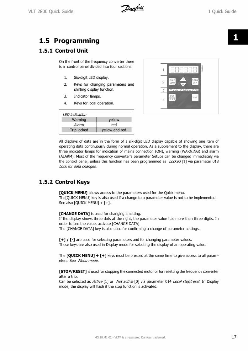
On the front of the frequency converter thereis a control panel divided into four sections.
1. Six-digit LED display.
2. Keys for changing parameters andshifting display function.
3. Indicator lamps.
4. Keys for local operation.
LED indicationWarning yellowAlarm red
Trip locked yellow and red
All displays of data are in the form of a six-digit LED display capable of showing one item ofoperating data continuously during normal operation. As a supplement to the display, there arethree indicator lamps for indication of mains connection (ON), warning (WARNING) and alarm(ALARM). Most of the frequency converter's parameter Setups can be changed immediately viathe control panel, unless this function has been programmed as Locked [1] via parameter 018Lock for data changes.
1.5.2 Control Keys
[QUICK MENU] allows access to the parameters used for the Quick menu.The[QUICK MENU] key is also used if a change to a parameter value is not to be implemented.See also [QUICK MENU] + [+].
[CHANGE DATA] is used for changing a setting.If the display shows three dots at the right, the parameter value has more than three digits. Inorder to see the value, activate [CHANGE DATA]The [CHANGE DATA] key is also used for confirming a change of parameter settings.
[+] / [-] are used for selecting parameters and for changing parameter values.These keys are also used in Display mode for selecting the display of an operating value.
The [QUICK MENU] + [+] keys must be pressed at the same time to give access to all param-eters. See Menu mode.
[STOP/RESET] is used for stopping the connected motor or for resetting the frequency converterafter a trip.Can be selected as Active [1] or Not active [0] via parameter 014 Local stop/reset. In Displaymode, the display will flash if the stop function is activated.
VLT 2800 Quick Guide 1 Quick Guide
MG.28.M1.02 - VLT® is a registered Danfoss trademark 17
1

NB!If the [STOP/RESET] key is set at Not active [0] in parameter 014 Local stop/re-set, and there is no stop command via the digital inputs or serial communication,the motor can only be stopped by disconnecting the mains voltage to the frequencyconverter.
[START] is used for starting the frequency converter. It is always active, but the [START] keycannot override a stop command.
1.5.3 Manual initialisation
Disconnect mains voltage. Hold the [QUICK MENU] + [+] + [CHANGE DATA] keys down whilesimultaneously reconnecting the mains voltage. Release the keys; the frequency converter hasnow been programmed for the factory setting.
1.5.4 Display Readout States
In normal operation, one item of operating data can be displayed continuously at the operator'sown choice. By means of the [+/-] keys the following options can be selected in Display mode:
• Output frequency [Hz]
• Output current [A]
• Output voltage [V]
• Intermediate circuit voltage [V]
• Output power [kW]
• Scaled output frequency fout x p008
1.5.5 Menu mode
In order to enter the Menu mode [QUICK MENU] + [+] must be activated at the same time.In Menu mode, most of the frequency converter parameters can be changed. Scroll through theparameters using the [+/-] keys. While scrolling in the Menu mode proceeds, the parameternumber will flash.
1.5.6 Quick menu
Using the [QUICK MENU] key, it is possible to access the 12 most important parameters of thefrequency converter. After programming, the frequency converter is in most cases ready for op-eration. When the [QUICK MENU] key is activated in Display mode, the Quick menu starts. Scrollthrough the quick menu using the [+/-] keys and change the data values by first pressing[CHANGE DATA] and then changing the parameter value with the [+/-] keys.The Quick menu parameters are shown in section Parameter Lists.
1 Quick Guide VLT 2800 Quick Guide
18 MG.28.M1.02 - VLT® is a registered Danfoss trademark
1
1.5.7 Hand Auto
During normal operation the frequency converter is in Auto mode, where the reference signal isgiven externally, analog or digital via the control terminals. However, in Hand mode, it is possibleto give the reference signal locally via the control panel.
On the control terminals, the following control signals will remain active when Hand mode is ac-tivated:
Hand Start (LCP2) Quick Stop Inverse ThermistorOff Stop (LCP2) Stop Inverse Precise Stop InverseAuto Start (LCP2) Reversing Precise Stop/StartReset DC Braking Inverse JogCoasting Stop Inverse Setup Select LSB Stop Comm. Via Serial Comm.Reset and Coasting Stop Inverse Setup Select MSB
Switching between Auto- and Hand mode:By activating the [Change Data] key in [Display Mode], the display will indicate the mode of thefrequency converter.Scroll up/down in order to switch to Hand mode, the reference can be changed by using [+]/[-].
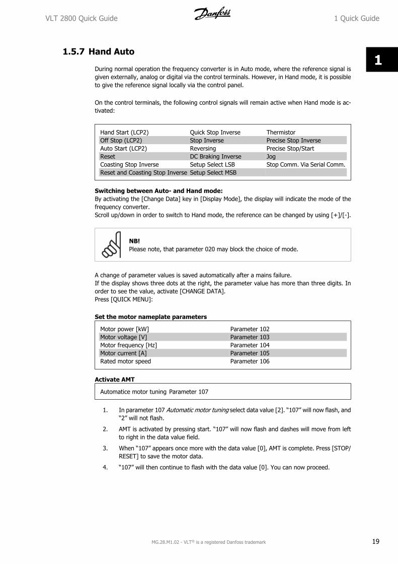
NB!Please note, that parameter 020 may block the choice of mode.
A change of parameter values is saved automatically after a mains failure.If the display shows three dots at the right, the parameter value has more than three digits. Inorder to see the value, activate [CHANGE DATA].Press [QUICK MENU]:
Set the motor nameplate parameters
Motor power [kW] Parameter 102Motor voltage [V] Parameter 103Motor frequency [Hz] Parameter 104Motor current [A] Parameter 105Rated motor speed Parameter 106
Activate AMT
Automatice motor tuning Parameter 107
1. In parameter 107 Automatic motor tuning select data value [2]. “107” will now flash, and“2” will not flash.
2. AMT is activated by pressing start. “107” will now flash and dashes will move from leftto right in the data value field.
3. When “107” appears once more with the data value [0], AMT is complete. Press [STOP/RESET] to save the motor data.
4. “107” will then continue to flash with the data value [0]. You can now proceed.
VLT 2800 Quick Guide 1 Quick Guide
MG.28.M1.02 - VLT® is a registered Danfoss trademark 19
1

NB!VLT 2880-2882 do not have the AMT function.
Set reference range
Min. reference, RefMIN Parameter 204Max. reference, RefMAX Parameter 205
Set ramp time
Ramp-up time [s] Parameter 207Ramp-down time [s] Parameter 208
In parameter 002, Local/remote control, the frequency converter mode can be selected as Remoteoperation [0], i.e. via the control terminals, or Local [1], i.e. via the control unit.
Set the control location to Local [1]
Local/remote operation = Local [1], Par. 002
Set the motor speed by adjusting theLocal reference
Local reference, Par. 003
1.6 Motor StartPress [START] to start the motor. Set the motor speed by adjusting par. 003, Local reference.
Check whether the direction of rotation of the motor shaft is clockwise. If not, exchange any twophases on the motor cable.Press [STOP/RESET] to stop the motor.Press [QUICK MENU] to return to display mode.[QUICK MENU] + [+] keys must be pressed simultaneously to give access to all parameters.
1 Quick Guide VLT 2800 Quick Guide
20 MG.28.M1.02 - VLT® is a registered Danfoss trademark
1

1.7 Connection ExamplesMore examples can be found in the Operating Instructions (MG.27.AX.YY).
1.7.1 Start/Stop
Start/stop using terminal 18 and coasting stop using terminal 27.
Par. 302 Digital input = Start [7]
Par. 304 Digital input = Coastingstop inverted [2]
For Precise start/stop the following settingsare made:
Par. 302 Digital input = Precise start/stop [27]
Par. 304 Digital input = Coastingstop inverted [2]
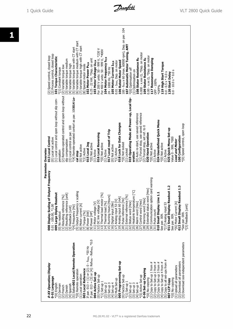
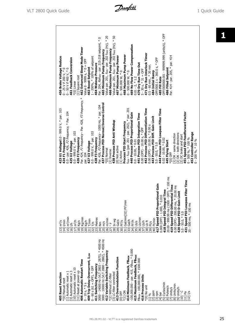
1.8 Parameter ListAll parameters are listed in the following. For information on conversion index, data type andfurther descriptions, please see Operating Instructions (MG.27.AX.YY) or Design Guide (MG.27.EX.YY).
For external communication, please see dedicated literature (see section Available Literature).
NB!Use MCT-10 and USB to RS485 converter to change parameters.
VLT 2800 Quick Guide 1 Quick Guide
MG.28.M1.02 - VLT® is a registered Danfoss trademark 21
1
Par
amet
er O
verw
iev
0-X
X O
pera
tion
/Dis
play
0-0
1 La
ngua
ge*[
0] E
nglis
h[1
] G
erm
an[2
] Fr
ench
[3]
Dan
ish
[4]
Span
ish
[5]
Ital
ian0
02 L
ocal
/Rem
ote
Ope
rati
on*[
0] R
emot
e op
erat
ion
[1]
Loca
l ope
ratio
n00
3 Lo
cal R
efer
ence
If p
ar. 0
13 =
[1]
or
[2]:
0 -
fM
AX, *
50 H
zIf
par
. 013
= [
3] o
r [4
]: R
efM
IN -
Ref
MAX
, *0
.000
4 A
ctiv
e Se
t-u
p[0
] Fa
ctor
y Se
t-up
*[1]
Set
-up
1[2
] Se
t-up
2[3
] Se
t-up
3[4
] Se
t-up
4[5
] M
ulti
Set-
up00
5 P
rogr
amm
ing
Set-
up
[0]
Fact
ory
Set-
up*[
1] S
et-u
p 1
[2]
Set-
up 2
[3]
Set-
up 3
[4]
Set-
up 4
*[5]
Act
ive
Set-
up0-
06
Set-
up
Cop
yin
g*[
0] N
o co
pyin
g[1
] Co
py t
o Se
t-up
1 f
rom
#[2
] Co
py t
o Se
t-up
2 f
rom
#[3
] Co
py t
o Se
t-up
3 f
rom
#[4
] Co
py t
o Se
t-up
4 f
rom
#[5
] Co
py t
o al
l set
-ups
fro
m #
007
LCP
Cop
y*[
0] N
o co
pyin
g[1
] U
ploa
d al
l par
amet
ers
[2]
Dow
nloa
d al
l par
amet
ers
[3]
Dow
nloa
d si
ze-in
depe
nden
t pa
ram
eter
s
00
8 D
ispl
ay S
calin
g of
Ou
tpu
t Fr
equ
ency
0.01
- 1
00.0
0, *
1.00
009
Lar
ge D
ipla
y R
eado
ut
[0]
No
read
out
[1]
Res
ultin
g re
fere
nce
[%]
[2]
Res
ultin
g re
fere
nce
[uni
t][3
] Fe
edba
ck [
unit]
*[4]
Fre
quen
cy [
Hz]
[5]
Out
put
freq
uenc
y x
scal
ing
[6]
Mot
or c
urre
nt [
A][7
] To
rque
[%
][8
] Po
wer
[kW
][9
] Po
wer
[H
P][1
1] M
otor
vol
tage
[V]
[12]
DC
link
volta
ge [
V][1
3] T
herm
al lo
ad m
otor
[%
][1
4] T
herm
al lo
ad [
%]
[15]
Run
ning
hou
rs [
Hou
rs]
[16]
Dig
ital i
nput
[Bi
n][1
7] A
nalo
g in
put
53 [
V][1
9] A
nalo
g in
put
60 [
mA]
[20]
Pul
se r
efer
ence
[H
z][2
1] E
xter
nal r
efer
ence
[%
][2
2] S
tatu
s w
ord
[Hex
][2
5] H
eats
ink
tem
pera
ture
[°C
][2
6] A
larm
wor
d [H
ex]
[27]
Con
trol
wor
d [H
ex]
[28]
War
ning
wor
d [H
ex]
[29]
Ext
ende
d st
atus
wor
d [H
ex]
[30]
Com
mun
icat
ion
optio
n ca
rd w
arni
ng[3
1] P
ulse
cou
nt0
10 S
mal
l Dis
play
Lin
e 1.
1Se
e pa
r. 0
09.
*[17
] An
alog
inpu
t 53
011
Sm
all D
ispl
ay R
eado
ut
1.2
See
par.
009
.*[
6] M
otor
Cur
rent
[A]
012
Sm
all D
ispl
ay R
eado
ut
1.3
*See
par
. 00
9.*[
3] F
eedb
ack
[uni
t]
013
Loc
al C
ontr
ol[0
] Lo
cal n
ot a
ctiv
e[1
] Lo
cal c
ontr
ol a
nd o
pen
loop
with
out
slip
com
-pe
nsat
ion
[2]
Rem
ote-
oper
ated
con
trol
and
ope
n lo
op w
ithou
tsl
ip c
ompe
nsat
ion
[3]
Loca
l con
trol
as
par.
100
*[4]
Rem
ote-
oper
ated
con
torl
as p
ar. 10
001
4 Lo
-ca
l sto
p[0
] N
ot a
ctiv
e*[
1] A
ctiv
e01
5 L
ocal
Jog
*[0]
Not
act
ive
[1]
Activ
e01
6 L
ocal
Rev
ersi
ng
*[0]
Not
act
ive
[1]
Activ
e01
7 L
ocal
res
et o
f Tr
ip[0
] N
ot a
ctiv
e*[
1] A
ctiv
e01
8 L
ock
for
Dat
a C
han
ges
*[0]
Not
lock
ed[1
] Lo
cked
019
Ope
rati
ng
Mod
e at
Pow
er-u
p, L
ocal
Op-
erat
ion
[0]
Auto
re-
star
t, u
se s
aved
ref
eren
ce*[
1] F
orce
d st
op, us
e sa
ved
refe
renc
e[2
] Fo
rced
sto
p, s
et r
ef. t
o 0
020
Han
d O
pera
tion
*[0]
Not
act
ive
[1]
Activ
e02
4 U
serd
efin
ed Q
uic
k M
enu
*[0]
Not
act
ive
[1]
Activ
e02
5 Q
uic
k M
enu
Set
-up
Valu
e 0
- 99
9, *
000
Load
and
Mot
or1
00
Con
figu
rati
on*[
0] S
peed
con
trol
, ope
n lo
op
[2]
Spee
d co
ntro
l, cl
osed
loop
[3]
Proc
ess
cont
rol,
clos
ed lo
op1
01 T
orqu
e C
har
acte
rist
ic*[
1] C
onst
ant
torq
ue[2
] Va
riabl
e to
rque
low
[3]
Varia
ble
torq
ue m
ediu
m[4
] Va
riabl
e to
rque
hig
h[5
] Va
riabl
e to
rque
low
with
CT
star
t[6
] Va
riabl
e to
rque
med
ium
with
CT
star
t[7
] Va
riabl
e to
rque
hig
h w
ith C
T st
art
[8]
Spec
ial m
otor
mod
e10
2 M
otor
Pow
er P
M,N
0.25
- 2
2 kW
, *D
ep. on
uni
t1
03 M
otor
Vol
tage
UM
,N
For
200
V un
its:
50 -
999
V, *
230
VFo
r 40
0 V
units
: 50
- 9
99 V
, *4
00V
104
Mot
or F
requ
ency
fM
,N
24 -
100
0 H
z, *
50 H
z10
5 M
otor
Cu
rren
t I M
,N
0.01
- I
MAX
, Dep
. on
mot
or1
06 R
ated
Mot
or S
peed
100
- f M
,N x
60
(max
. 600
00 r
pm),
Dep
. on
par.
104
107
Au
tom
atic
Mot
or T
un
ing,
AM
T*[
0] O
ptim
isat
ion
off
[1]
Opt
imis
atio
n on
108
Sta
tor
Res
ista
nce
RS
0.00
0 -
x.xx
x Ω
, *D
ep. o
n m
otor
109
Sta
tor
Res
ista
nce
XS
0.00
- x
.xx Ω
, *D
ep. o
n m
otor
117
Res
onan
ce D
ampi
ngO
FF -
100
%*O
FF%
119
Hig
h S
tart
Tor
que
0.0
- 0.
5 s
* 0.
0 s
120
Sta
rt D
elay
0.0
- 10
.0 s
* 0
.0 s
1 Quick Guide VLT 2800 Quick Guide
22 MG.28.M1.02 - VLT® is a registered Danfoss trademark
1

121
Star
t Fu
nct
ion
[0]
DC
hold
dur
ing
star
t de
lay
time
[1]
DC
brak
e du
ring
star
t de
lay
time
*[2]
Coa
stin
g du
ring
star
t de
lay
time
[3]
Star
t fr
eque
ncy/
volta
ge c
lock
wis
e[4
] St
art
freq
uenc
y/vo
ltage
in r
efer
ence
dire
ctio
n12
2 Fu
ncti
on a
t St
op*[
0] C
oast
ing
[1]
DC
hold
123
Min
. Fre
quen
cy fo
r A
ctiv
atio
n o
f Fu
ncti
onat
Sto
p0.
1 -
10 H
z, *
0.1
Hz
126
DC
Bra
ke T
ime
0 -
60 s
, *10
s12
7 D
C b
rake
cu
t-in
Fre
quen
cy0.
0 (O
FF)
- Pa
r. 2
02, *
OFF
128
Ther
mal
Mot
or P
rote
ctio
n*[
0] N
o pr
otec
tion
[1]
Ther
mis
tor
war
ning
[2]
Ther
mis
tor
trip
[3]
ETR
war
ning
1[4
] ET
R tr
ip 1
[5]
ETR
war
ning
2[6
] ET
R tr
ip 2
[7]
ETR
war
ning
3[8
] ET
R tr
ip 3
[9]
ETR
war
ning
4[1
0] E
TR t
rip 4
130
Star
t Fr
equ
ency
0.0
- 10
.0 H
z, *
0.0
Hz
131
Init
ial V
olta
ge0.
0 -
200.
0 V,
*0.
0 V
132
DC
Bra
ke V
olta
ge0
- 10
0% o
f m
ax. D
C br
ake
volta
ge, *0
%13
3 St
art
Vol
tage
0.00
- 1
00.0
0 V,
*D
ep. on
uni
t13
4 Lo
ad C
ompe
nsat
ion
0.0
- 30
0.0%
, 10
0,0%
135
U/f
Rat
io0.
00 -
20.
00 a
t H
z, *
Dep
. on
unit
136
Slip
Com
pen
sati
on0
- 15
0 %
* 1
00 %
-500
. +
500%
of r
ated
slip
com
-pe
nsat
ion,
*10
0%1
37 D
C H
old
Vol
tage
0 -
100%
if n
ax. D
C ho
ld v
olta
ge, *0
%1
38 B
rake
Cu
t O
ut
Val
ue
0.5
- 13
2.0/
1000
.0 H
z, *
3.0
Hz
139
Bra
ke C
ut
In F
requ
ency
0.5
- 13
2.0/
1000
.0 H
z, *
3.0
Hz
140
Cu
rren
t, M
inim
um
Val
ue0%
- 1
00%
of
inve
rter
out
put
curr
ent
142
Lea
kage
Rea
ctan
ce X
L
0.00
0 -
xxx.
xxx Ω
, *D
ep-
on m
otor
143
In
tern
al F
an C
ontr
ol*[
0] A
utom
atic
[1]
Alw
ays
switc
hed
on[2
] Al
way
s sw
itche
d of
f1
44 G
ain
AC
Bra
ke1.
00 -
1.5
0, *
1.30
146
Res
et V
olta
ge V
ecto
r*[
0] O
ff[1
] Re
set
Ref
eren
ces
and
Lim
its2
00 O
utpu
t Fr
equ
ency
Ran
ge*[
0] O
nly
cloc
kwis
e, 0
- 1
32 H
z[1
] Bo
th d
irect
ions
, 0
- 13
2 H
z[2
] Co
unte
rclo
ckw
ise
only
, 0 -
132
Hz
[4]
Both
dire
ctio
ns, 0
- 10
00 H
z[5
] Co
unte
rclo
kcw
ise
only
, 0 -
100
0 H
z20
1 O
utpu
t Fr
equ
ency
Low
Lim
it, f
MIN
0.0
- f M
AX, *
0.0
Hz
20
2 O
utpu
t Fr
equ
ency
Hig
h L
imit
, FM
AX
f MIN
- 1
32/1
000
Hz
(par
. 200
Out
put f
requ
ency
rang
e, 1
32 H
z2
03 R
efer
ence
Ran
ge[0
] M
in. r
efer
ence
- M
ax. re
fere
nce
[1]
Anal
og I
nput
53
-Max
. ref
eren
ce -
+M
ax. r
efer
-en
ce
204
Min
imu
m R
efer
ence
, Ref
MIN
Par.
100
[0].
-100
,000
.000
- pa
r. 2
05 R
efM
AX, *
0.00
0H
zPa
r. 1
00 [
1]/[
3], -
par.
414
Min
imum
feed
back
- pa
r.20
5 Re
f MAX
, *0
.000
rpm
/par
. 41
620
5 m
axim
um R
efer
ence
, Ref
MA
X
Par.
100
[0].
Par
. 204
Ref
MIN
- 10
00.0
00 H
z, *
50.0
00H
zPa
r. 1
00 [
1]/[
3]. Pa
r. 2
04 R
efM
IN
- Pa
r. 4
15 M
axFe
edba
ck, *5
0.00
0 rp
m/p
ar. 41
620
6 R
amp
Type
*[0]
Lin
ear
[1]
Sin
shap
ed[2
] Si
n220
7 R
amp-
up
Tim
e 1
0.02
- 3
600.
00 s
, * 3
.00
s (V
LT 2
803
- 28
75),
*10
.00
(288
0 -
2882
)20
8 R
amp-
dow
n Ti
me
10.
02 -
360
0.00
s, *
3.0
0 s
(VLT
280
3 -
2875
), *
10.0
0 (2
880
- 28
82)
209
Ram
p-u
p Ti
me
20.
02 -
360
0.00
s, *
3.0
0 s
(VLT
280
3 -
2875
), *
10.0
0 (2
880
- 28
82)
210
Ram
p-do
wn
Tim
e 2
0.02
- 3
600.
00 s
, * 3
.00
s (V
LT 2
803
- 28
75),
*10
.00
(288
0 -
2882
)21
1 J
og R
amp
Tim
e0.
02 -
360
0.00
s, *
3.0
0 s
(VLT
280
3 -
2875
), *
10.0
0 (2
880
- 28
82)
212
Qu
ick-
stop
Ram
p-do
wn
Tim
e0.
02 -
360
0.00
s, *
3.0
0 s
(VLT
280
3 -
2875
), *
10.0
0 (2
880
- 28
82)
213
Jog
Freq
uen
cy0.
0 -
Par.
202
Out
put F
requ
ency
Hig
h Li
mit,
f MAX
214
Ref
eren
ce F
un
ctio
n*[
0] S
um[1
] Rel
ativ
e[2
] Ex
tern
al/p
rese
t21
5-2
18 P
rese
t re
fere
nce
1-4
0.0
- 40
0.0
Hz
* 0.
0 H
z-10
0.00
% -
+10
0.00
%, *
0.00
%21
9 C
atch
Up/
Slow
Dow
n R
efer
ence
0.00
- 1
00%
of
the
give
n re
fere
nce,
* 0
.00%
221
Cu
rren
t Li
mit
, ILI
M
0 -
xxx.
x% o
f pa
r. 1
05, *
160
%2
23 W
arn
ing,
Low
Cu
rren
t, I
LOW
0.0
- pa
r. 2
24 W
arni
ng: H
igh
Curr
ent,
I HIG
H, *
0.0
A2
24 W
arn
ing:
Hig
h C
urr
ent,
IH
IGH
0 -
I MAX
, * I
MAX
225
War
nin
g: L
ow F
requ
ency
, fLO
W
0.0
- pa
r. 2
26 W
arn.
: H
igh
freq
uenc
y, f
HIG
H, *
0.0
Hz
226
War
nin
g: H
igh
Fre
quen
cy f
HIG
H
If p
ar. 2
00 =
[0]
/[1]
. Par
. 225
f LO
W -
132
Hz,
* 1
32.0
Hz
If p
ar. 2
00 [
2]/[
3]. P
ar 2
25 f L
OW
- 1
000
Hz,
* 1
32.0
Hz
227
War
nin
g: L
ow F
eedb
ack,
FB
LOW
0.0
- 40
0.0
Hz
* 0.
0 H
z-10
0,00
0.00
0 -
par.
228
War
n.:
FBH
IGH, *
-400
0.00
02
28 W
arn
ing:
Hig
h F
eedb
ack,
FB
HIG
H
Par.
227
War
n.:
FBLO
W -
100
,000
.000
, *
4000
.000
22
9 F
requ
ency
Byp
ass,
Ban
dwid
th0
(OFF
) -
100
Hz,
* 0
Hz
230
- 2
31
Freq
uenc
y B
ypas
s 1
- 2
0 -
100
Hz,
*0.
0 H
zIn
puts
and
Out
puts
302
Ter
min
al 1
8 D
igit
al I
npu
t[0
] N
o fu
nctio
n[1
] Re
set
[2]
Coas
ting
stop
inve
rse
[3]
Rese
t an
d co
astin
g in
vers
e[4
] Q
uick
-sto
p in
vers
e[5
] D
C br
akin
g in
vers
e[6
] St
op in
vers
e*[
7] S
tart
[8]
Puls
e st
art
[9]
Reve
rsin
g[1
0] R
ever
sing
[11]
Sta
rt C
lock
wis
e[1
2] S
tart
cou
nter
cloc
kwis
e[1
3] J
og[1
4] F
reez
e re
fere
nce
[15]
Fre
eze
outp
ut f
requ
ency
VLT 2800 Quick Guide 1 Quick Guide
MG.28.M1.02 - VLT® is a registered Danfoss trademark 23
1

[16]
Spe
ed u
p[1
7] S
peed
dow
n[1
9] C
atch
up
[20]
Slo
w d
own
[21]
Ram
p 2
[22]
Pre
set
ref,
LSB
[23]
Pre
set
ref,
MSB
[24]
Pre
set
refe
renc
e on
[25]
The
rmis
tor
[26]
Pre
cise
sto
p[2
7] P
reci
se S
tart
Sto
p[3
1] S
elec
tion
of S
et-u
p, L
SB[3
2] S
elec
tion
of S
et-u
p, M
SB[3
3] R
eset
and
sta
rt[3
4 Pu
lse
coun
ter
star
t30
3 Te
rmin
al 1
9 D
igit
al I
npu
tSe
e pa
r. 3
02 *
[9]
Rev
ersi
ng30
4 Te
rmin
al 2
7 D
igit
al I
npu
t[0
] N
o fu
nctio
n[1
] Re
set
[2]
Coas
ting
stop
inve
rse
*[3]
Res
et a
nd c
oast
ing
inve
rse
[4]
Qui
ck-s
top
inve
rse
[5]
DC
brak
ing
inve
rse
[6]
Stop
inve
rse
[7]
Star
t[8
] Pu
lse
star
t[9
] Re
vers
ing
[10]
Rev
ersi
ng[1
1] S
tart
Clo
ckw
ise
[12]
Sta
rt c
ount
ercl
ockw
ise
[13]
Jog
[14]
Fre
eze
refe
renc
e[1
5] F
reez
e ou
tput
fre
quen
cy[1
6] S
peed
up
[17]
Spe
ed d
own
[19]
Cat
ch u
p[2
0] S
low
dow
n[2
1] R
amp
2[2
2] P
rese
t re
f, LS
B[2
3] P
rese
t re
f, M
SB[2
4] P
rese
t re
fere
nce
on[2
5] T
herm
isto
r[2
6] P
reci
se s
top
[27]
Pre
cise
Sta
rt S
top
[31]
Sel
ectio
n of
Set
-up,
LSB
[32]
Sel
ectio
n of
Set
-up,
MSB
[33]
Res
et a
nd s
tart
[34
Puls
e co
unte
r st
art
305
Ter
min
al 2
9 D
igit
al I
npu
tSe
e pa
r. 3
05 *
[13
] Jo
g3
07Te
rmin
al 3
3 D
igit
al I
npu
t*[
0] N
o fu
nctio
n[1
] Re
set
[2]
Coas
ting
stop
inve
rse
[3]
Rese
t an
d co
astin
g in
vers
e[4
] Q
uick
-sto
p in
vers
e[5
] D
C br
akin
g in
vers
e[6
] St
op in
vers
e[7
] St
art
[8]
Puls
e st
art
[9]
Reve
rsin
g[1
0] R
ever
sing
[11]
Sta
rt C
lock
wis
e[1
2] S
tart
cou
nter
cloc
kwis
e[1
3] J
og[1
4] F
reez
e re
fere
nce
[15]
Fre
eze
outp
ut f
requ
ency
[16]
Spe
ed u
p[1
7] S
peed
dow
n[1
9] C
atch
up
[20]
Slo
w d
own
[21]
Ram
p 2
[22]
Pre
set
ref,
LSB
[23]
Pre
set
ref,
MSB
[24]
Pre
set
refe
renc
e on
[28]
Pul
se r
efer
ence
[29]
Pul
se f
eedb
ack
[30]
Pul
se in
put
[31]
Sel
ectio
n of
Set
-up,
LSB
[32]
Sel
ectio
n of
Set
-up,
MSB
[33]
Res
et a
nd s
tart
308
Ter
min
al 5
3, A
nalo
g In
put
Vol
tage
[0]
No
func
tion
*[1]
Ref
eren
ce[2
] Fe
edba
ck[3
] W
obbl
e 30
9 T
erm
inal
53
Min
. Sca
ling
0.0
- 10
.0 V
, * 0
.0 V
310
Ter
min
al 5
3 M
ax. S
calin
g0.
0 -
10.0
V, *
10.
0 V
314
Ter
min
al 6
0 A
nalo
g In
put
Cur
ren
t[0
] N
o fu
nctio
n[1
] Ref
eren
ce*[
2] F
eedb
ack
[10]
Wob
ble
315
Ter
min
al 6
0 M
in. S
calin
g0.
0 -
20.0
mA,
* 4
.0 m
A31
6 T
erm
inal
60
Max
. Sca
ling
0.0
- 20
.0 m
A, *
20.
0 m
A31
7 T
ime
Ou
t1
- 99
s *
10
s31
8*[
0] N
o op
erat
ion
[1]
Free
ze o
utpu
t fr
eque
ncy
[2]
Stop
[3]
Jog
[4]
Max
spe
ed[5
] St
op a
nd t
rip31
9 A
nal
og o
utpu
t te
rmin
al 4
2[0
] N
o fu
nctio
n[1
] Ex
tern
al r
efer
ence
min
. - m
ax. 0
- 2
0 m
A[2
] Ex
tern
al r
efer
ence
min
. - m
ax. 4-
20
mA
[3]
Feed
back
min
. - m
ax. 0
-20
mA
[4]
Feed
back
min
. - m
ax. 4
- 20
mA
[5]
Out
put
freq
uenc
y 0
- m
ax 0
-20
mA
[6]
Out
put
freq
uenc
y 0
- m
ax 4
-20
mA
*[7]
Out
put
curr
ent
0 -
I IN
V 0-
20 m
A[8
] O
utpu
t cu
rren
t 0
- I I
NV
4-20
mA
[9]
Out
put
pow
er 0
-PM
,N 0
-20
mA
[10]
Out
put
pow
er 0
-PM
,N 4
-20
mA
[11]
Inv
erte
r te
mpe
ratu
re 2
0-10
0 °C
0-2
0 m
A[1
2] I
nver
ter
tem
pera
ture
20-
100 °C
4-2
0 m
A32
3 R
elay
Ou
tpu
t 1
-3[0
] N
o fu
nctio
n*[
1] U
nit
read
y[2
] En
able
/no
war
ning
[3]
Runn
ing
[4]
Run
ning
in r
efer
ence
, no
war
ning
[5]
Run
ning
, no
war
ning
[6]
Run
ning
in r
efer
ence
ran
ge, n
o w
arni
ngs
[7]
Rea
dy -
mai
ns v
olta
ge w
ithin
ran
ge[8
] Al
arm
or
war
ning
[9]
Curr
ent
high
er t
han
curr
ent
limit
[10]
Ala
rm[1
1] O
utpu
t fr
eque
ncy
high
er t
han
f LO
W
[12]
Out
put
freq
uenc
y lo
wer
tha
n f H
IGH
[13]
Out
put
curr
ent
high
er t
han
I LO
W
[14]
Out
put
curr
ent
low
er t
han
I HIG
H p
ar. 22
4[1
5] F
eedb
ack
high
er t
han
FBLO
W
[16]
Fee
dbac
k lo
wer
tha
n FB
HIG
H p
ar. 2
28[1
7] R
elay
123
[18]
Rev
ersi
ng[1
9] T
herm
al w
arni
ng[2
0] L
ocal
ope
ratio
n[2
2] O
ut o
f fr
eque
ncy
rang
e pa
r. 2
25/2
26[2
3] O
ut o
f cu
rren
t ra
nge
[24]
Out
of
feed
back
ran
ge[2
4] M
echa
nica
l bra
ke c
ontr
ol[2
5] C
ontr
ol w
ord
bit
1132
7 P
uls
e re
fere
nce
/fee
dbac
k15
0 -
6760
0 H
z, *
500
0 H
z3
28 M
axim
um P
uls
e 29
150
- 67
600
Hz,
* 5
000
Hz
341
Dig
ital
/Pu
lse
Ou
tpu
t Te
rmin
al 4
6[0
] U
nit
read
yPa
r. [
0] -
[20
], s
ee p
ar. 32
3[2
1] P
ulse
ref
eren
cePa
r. [
22]
- [2
5], s
ee p
ar. 3
23[2
6] P
ulse
fee
dbac
k[2
7] O
utpu
t fr
eque
ncy
[28]
Pul
se c
urre
nt[2
9] P
ulse
pow
er[3
0] P
ulse
tem
pera
ture
342
Ter
min
al 4
6, m
ax. P
ulse
Sca
ling
150
- 10
000
Hz,
* 5
000
Hz
343
Pre
cise
Sto
p Fu
nct
ion
*[0]
Pre
cise
ram
p st
op[1
] Co
unte
r st
op w
ith r
eset
[2]
Coun
ter
stop
with
out
rese
t[3
] Sp
eed-
com
pens
ated
cou
nter
sto
p[4
] Sp
eed-
com
pens
ated
sto
p w
ith r
eset
[5]
Spee
d-co
mpe
nsat
ed s
top
with
out
rese
t3
44 C
ount
er V
alue
0 -
9999
99, *
1000
00 p
ulse
s3
49 S
peed
Com
p D
elay
0 m
s -
100
ms,
* 1
0 m
sSp
ecia
l Fun
ctio
ns4
00 B
rake
Fun
ctio
n[0
] O
FF[1
] Res
isto
r br
ake
[4]
AC b
rake
[5]
Load
sha
ring
1 Quick Guide VLT 2800 Quick Guide
24 MG.28.M1.02 - VLT® is a registered Danfoss trademark
1
405
Res
et F
un
ctio
n*[
0] M
anua
l res
et[1
] Au
tom
atic
res
et x
1[3
] Au
tom
atic
res
et x
3[1
0] A
utom
atic
res
et x
10
[11]
Res
et a
t po
wer
-up
406
Aut
omat
ic R
esta
rt T
ime
0 -
10 s
, * 5
s40
9 Tr
ip D
elay
Ove
rcu
rren
t, I
LIM
0 -
60 s
(61
= O
FF),
* O
FF41
1 Sw
itch
ing
Freq
uen
cy30
00 -
140
00 H
z (V
LT 2
803
- 28
75),
* 4
500
Hz
3000
- 1
0000
Hz
(VLT
288
0 -
2882
), *
450
0 H
z41
2 V
aria
ble
Swit
chin
g Fr
equ
ency
*[2]
With
out
LC-f
ilter
[3]
LC-f
ilter
con
nect
ed41
3 O
verm
odul
atio
n Fu
nct
ion
[0]
OFF
*[1]
ON
414
Min
imum
Fee
dbac
k, F
BM
IN
-100
,000
.000
- p
ar. 41
5, F
B MAX
, *
0.00
041
5 M
axim
um
Fee
dbac
k, F
BM
AX
FBM
IN -
100
,000
.000
, * 1
500.
000
416
Pro
cess
Un
its
*[0]
No
unit
[1]
%[2
] pp
m[3
] rp
m[4
] ba
r[5
] Cy
cles
/min
[6]
Puls
es/s
[7]
Uni
ts/s
[8]
Uni
ts/m
in[9
] U
nits
/h[1
0] °
C[1
1] P
a[1
2] I
/s
[13]
m3 /
s[1
4] l/
min
[15]
m3 /
min
[16]
l/h
[17]
m3 /
h[1
8] K
g/s
[19]
Kg/
min
[20]
Kg/
h[2
1] T
/min
[22]
T/h
[23]
Met
res
[24]
Nm
[25]
m/s
[26]
m/m
in[2
7] °
F[2
8] I
n w
g[2
9] G
al/s
[30]
Ft3
/s[3
1] G
al/m
in[3
2] F
t3/m
in[3
3] G
al/h
[34]
Ft3
/h[3
5] L
b/s
[36]
Lb/
min
[37]
Lb/
h[3
8] L
b ft
[39]
Ft/
s[4
0] F
t/m
in41
7 S
peed
PID
Pro
port
ion
al G
ain
0.00
0 (O
FF)
- 1.
000,
* 0
.010
418
Spe
ed P
ID I
nteg
ral T
ime
20.0
0 -
999.
99 m
s (1
000
- O
FF),
* 1
00 m
s4
19 S
peed
PID
Dif
fere
nti
al T
ime
0.00
(O
FF)
- 20
0.00
ms,
* 2
0.00
ms
420
Spe
ed P
ID D
-Gai
n L
imit
5.0
- 50
.0, *
5.0
421
Spe
ed P
ID L
owpa
ss F
ilter
Tim
e20
- 5
00 m
s, *
100
ms
423
U1
Vol
tage
0.0
- 99
9.0
V, *
par
. 10
342
4 F
1 F
requ
ency
0.0
- pa
r. 4
26, F
2 fr
eque
ncy,
* P
ar. 10
442
5 U
2 V
olta
ge0.
0 -
999.
0 V,
* p
ar. 1
0342
6 F
2 F
requ
ency
Par.
424
, F1
freq
uenc
y -
Par.
428
, F3
freq
uenc
y, *
par.
104
427
U3
Vol
tage
0.0
- 99
9.0
V, *
par
. 103
428
F3
Fre
quen
cyPa
r. 4
26, F
2 fr
eque
ncy
- 10
00 H
z, *
par
. 10
443
7 P
roce
ss P
ID N
orm
al/I
nve
rse
Con
trol
*[0]
Nor
mal
[1]
Inve
rse
438
Pro
cess
PID
Ant
i Win
dup
[0]
Not
act
ive
[1]
Activ
eP
roce
ss P
ID S
tart
Fre
quen
cyf M
IN -
fM
AX (
par.
201
- p
ar. 2
02),
* p
ar. 2
0144
0 P
roce
ss P
ID P
ropo
rtio
nal
Gai
n0.
0 -
10.0
0, *
0.0
144
1 P
roce
ss P
ID I
nte
grat
ion
Tim
e0.
00 (
OFF
) -
10.0
0 s,
* O
FF44
2 P
roce
ss P
ID D
iffe
ren
tiat
ion
Tim
e0.
00 (
OFF
) -
10.0
0 s,
* 0
.00
s44
3 P
roce
ss P
ID D
iff.
Gai
n L
imit
5.0
- 50
.0, *
5.0
444
Pro
cess
PID
Low
pass
Filt
er T
ime
0.02
- 1
0.00
, * 0
.02
445
Fly
ing
Sta
rt*[
0] O
FF[1
] O
K -
sam
e di
rect
ion
[2]
OK
- bo
th d
irect
ions
[2]
DC
brak
e an
d st
art
451
Spe
ed P
ID F
eedf
orw
ard
Fact
or0
- 50
0 %
, * 1
00 %
452
Con
trol
ler
Ran
ge0
- 20
0 %
, * 1
0 %
456
Bra
ke V
olta
ge R
educ
e0
- 25
V if
200
V, *
00
- 50
V if
400
V, *
046
1 Fe
edba
ck C
onve
rsio
n*[
0] L
inea
r[1
] Sq
uare
roo
t4
62 E
nhan
ced
Sle
ep M
ode
Tim
erVa
lue
0 -
9999
s, *
0 =
OFF
463
Boo
st S
etpo
int
1 -
200%
, * 1
00%
of
setp
oint
464
Wak
eup
Pre
ssur
ePa
r. 2
04, R
efM
IN -
par
. 21
5-21
8 se
tpoi
nt, *
04
65 M
inim
um
Pu
mp
Freq
uen
cyVa
lue
par.
201
, fM
IN -
par
. 20
2 f M
AX (
Hz)
, *
204
66 M
axim
um
Pu
mp
Freq
uen
cyVa
lue
par.
201
, fM
IN -
par
. 20
2 f M
AX (
Hz)
, *
504
67 M
inim
um
Pum
p P
ower
0 -
500.
000
W, *
04
68 M
axim
um
Pu
mp
Pow
er0
- 50
0.00
0 W
, *
046
9 N
o Fl
ow P
ower
Com
pen
sati
on0.
01 -
2, *
1.2
470
Dry
Ru
n T
ime
Ou
t5
- 30
s, *
31
= O
FF4
71 D
ry R
un
In
terl
ock
Tim
er0.
5 -
60 m
in.,
* 30
min
.4
84 I
niti
al R
amp
OFF
/000
.1 s
- 3
60.0
s, *
OFF
485
Fill
Rat
eO
FF/0
0000
0.00
1 -
9999
99.9
99 (
units
/s),
* O
FF4
86 F
illed
Set
poin
tPa
r. 4
14 -
par
. 20
5, *
par
. 41
4
VLT 2800 Quick Guide 1 Quick Guide
MG.28.M1.02 - VLT® is a registered Danfoss trademark 25
1

1.9.1 Warnings/alarm messages
No. Description W A T Cause of Problem2 Live zero error (LIVE ZERO
ERROR)X X X Voltage or current signal on terminals 53 or 60
is below 50% of preset value.4 Mains phase loss (MAINS
PHASE LOSS)X X X No phase on mains supply side.
5 Voltage warning high (DCLINK VOLTAGE HIGH)
X The intermediate circuit voltage exceeds the lim-it set.
6 Voltage warning low (DCLINK VOLTAGE LOW)
X The intermediate circuit voltage is lower the limitset.
7 Overvoltage (DC LINKOVERVOLT)
X X X The intermediate voltage exceeds the limit set.
8 Undervoltage (DC LINK UN-DERVOLT)
X X X The intermediate voltage is lower than the limitset.
9 Inverter overload (INVER-TER TIME)
X X The frequency converter is close to tripping dueto overload.
10 Motor overloaded ( MOTOR,TIME)
X X The motor is too hot due to overload.
11 Motor thermistor (MOTORTHERMISTOR)
X X Either the motor is too hot or the thermistor hasbeen disconnected.
12 Current limit (CURRENTLIMIT)
X X Output current is higher than set in par. 221.
13 Overcurrent (OVERCUR-RENT)
X X X The peak current limit has been exceeded.
14 Earth fault (EARTH FAULT) X X Discharge from output phases to earth.15 Switch mode fault (SWITCH
MODE FAULT) X X Fault in switch mode power supply.
16 Short-circuit (CURR. SHORTCIRCUIT)
X X Short-circuit on the motor terminals or in themotor.
17 Serial communication time-out (STD BUS TIMEOUT)
X X No serial communication to the frequency con-verter.
18 HPFB bus timeout (HPFBTIMEOUT)
X X No serial communication to the communicationoption card.
33 Out of frequency range(OUT FREQ RNG/ROT LIM)
X Output frequency has reached the limit set ineither par. 201 or par. 202.
34 HPFB communication fault(PROFIBUS OPT. FAULT)
X X Fault only occurs in fieldbus versions. Please seepar. 953 in fieldbus literature.
35 Inrush fault (INRUSHFAULT)
X X Connected to mains too many times within 1 mi-nute.
36 Overtemperature (OVER-TEMPERATURE)
X X The upper temperature limit has been exceeded.
37-45 Internal fault (INTERNALFAULT)
X X Please contact Danfoss.
W: Warning, A: Alarm, T: Trip locked
1 Quick Guide VLT 2800 Quick Guide
26 MG.28.M1.02 - VLT® is a registered Danfoss trademark
1
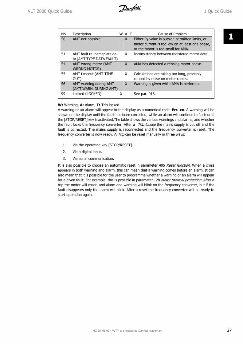
No. Description W A T Cause of Problem50 AMT not possible X Either RS value is outside permitted limits, or
motor current is too low on at least one phase,or the motor is too small for AMA.
51 AMT fault re. nameplate da-ta (AMT TYPE.DATA FAULT)
X Inconsistency between registered motor data.
54 AMT wrong motor (AMTWRONG MOTOR)
X AMA has detected a missing motor phase.
55 AMT timeout (AMT TIME-OUT)
X Calculations are taking too long, probablycaused by noise on motor cables.
56 AMT warning during AMT(AMT WARN. DURING AMT)
X Warning is given while AMA is performed.
99 Locked (LOCKED) X See par. 018.
W: Warning, A: Alarm, T: Trip lockedA warning or an alarm will appear in the display as a numerical code Err. xx. A warning will beshown on the display until the fault has been corrected, while an alarm will continue to flash untilthe [STOP/RESET] key is activated.The table shows the various warnings and alarms, and whetherthe fault locks the frequency converter. After a Trip locked the mains supply is cut off and thefault is corrected. The mains supply is reconnected and the frequency converter is reset. Thefrequency converter is now ready. A Trip can be reset manually in three ways:
1. Via the operating key [STOP/RESET].
2. Via a digital input.
3. Via serial communication.
It is also possible to choose an automatic reset in parameter 405 Reset function. When a crossappears in both warning and alarm, this can mean that a warning comes before an alarm. It canalso mean that it is possible for the user to programme whether a warning or an alarm will appearfor a given fault. For example, this is possible in parameter 128 Motor thermal protection. After atrip the motor will coast, and alarm and warning will blink on the frequency converter, but if thefault disappears only the alarm will blink. After a reset the frequency converter will be ready tostart operation again.
VLT 2800 Quick Guide 1 Quick Guide
MG.28.M1.02 - VLT® is a registered Danfoss trademark 27
1
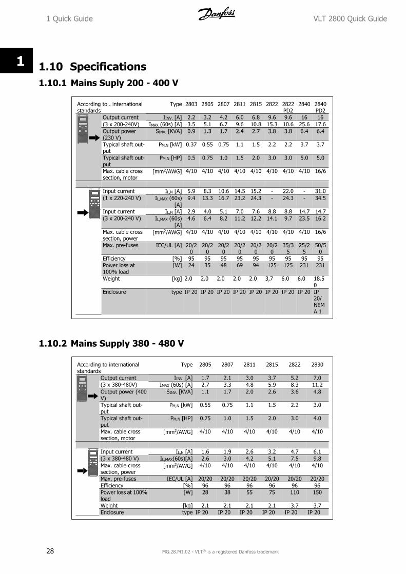
1.10 Specifications1.10.1 Mains Suply 200 - 400 V
According to . internationalstandards
Type 2803 2805 2807 2811 2815 2822 2822PD2
2840 2840PD2
Output current IINV. [A] 2.2 3.2 4.2 6.0 6.8 9.6 9.6 16 16(3 x 200-240V) IMAX (60s) [A] 3.5 5.1 6.7 9.6 10.8 15.3 10.6 25.6 17.6Output power(230 V)
SINV. [KVA] 0.9 1.3 1.7 2.4 2.7 3.8 3.8 6.4 6.4
Typical shaft out-put
PM,N [kW] 0.37 0.55 0.75 1.1 1.5 2.2 2.2 3.7 3.7
Typical shaft out-put
PM,N [HP] 0.5 0.75 1.0 1.5 2.0 3.0 3.0 5.0 5.0
Max. cable crosssection, motor
[mm2/AWG] 4/10 4/10 4/10 4/10 4/10 4/10 4/10 4/10 16/6
Input current IL,N [A] 5.9 8.3 10.6 14.5 15.2 - 22.0 - 31.0(1 x 220-240 V) IL,MAX (60s)
[A]9.4 13.3 16.7 23.2 24.3 - 24.3 - 34.5
Input current IL,N [A] 2.9 4.0 5.1 7.0 7.6 8.8 8.8 14.7 14.7(3 x 200-240 V) IL,MAX (60s)
[A]4.6 6.4 8.2 11.2 12.2 14.1 9.7 23.5 16.2
Max. cable crosssection, power
[mm2/AWG] 4/10 4/10 4/10 4/10 4/10 4/10 4/10 4/10 16/6
Max. pre-fuses IEC/UL [A] 20/20
20/20
20/20
20/20
20/20
20/20
35/35
25/25
50/50
Efficiency [%] 95 95 95 95 95 95 95 95 95Power loss at100% load
[W] 24 35 48 69 94 125 125 231 231
Weight [kg] 2.0 2.0 2.0 2.0 2.0 3,7 6.0 6.0 18.50
Enclosure type IP 20 IP 20 IP 20 IP 20 IP 20 IP 20 IP 20 IP 20 IP20/NEMA 1
1.10.2 Mains Supply 380 - 480 V
According to internationalstandards
Type 2805 2807 2811 2815 2822 2830
Output current IINV. [A] 1.7 2.1 3.0 3.7 5.2 7.0(3 x 380-480V) IMAX (60s) [A] 2.7 3.3 4.8 5.9 8.3 11.2Output power (400V)
SINV. [KVA] 1.1 1.7 2.0 2.6 3.6 4.8
Typical shaft out-put
PM,N [kW] 0.55 0.75 1.1 1.5 2.2 3.0
Typical shaft out-put
PM,N [HP] 0.75 1.0 1.5 2.0 3.0 4.0
Max. cable crosssection, motor
[mm2/AWG] 4/10 4/10 4/10 4/10 4/10 4/10
Input current IL,N [A] 1.6 1.9 2.6 3.2 4.7 6.1(3 x 380-480 V) IL,MAX(60s)[A] 2.6 3.0 4.2 5.1 7.5 9.8Max. cable crosssection, power
[mm2/AWG] 4/10 4/10 4/10 4/10 4/10 4/10
Max. pre-fuses IEC/UL [A] 20/20 20/20 20/20 20/20 20/20 20/20Efficiency [%] 96 96 96 96 96 96Power loss at 100%load
[W] 28 38 55 75 110 150
Weight [kg] 2.1 2.1 2.1 2.1 3.7 3.7Enclosure type IP 20 IP 20 IP 20 IP 20 IP 20 IP 20
1 Quick Guide VLT 2800 Quick Guide
28 MG.28.M1.02 - VLT® is a registered Danfoss trademark
1
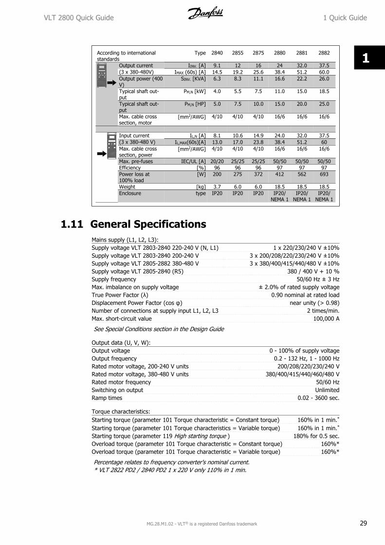
According to internationalstandards
Type 2840 2855 2875 2880 2881 2882
Output current IINV. [A] 9.1 12 16 24 32.0 37.5(3 x 380-480V) IMAX (60s) [A] 14.5 19.2 25.6 38.4 51.2 60.0Output power (400V)
SINV. [KVA] 6.3 8.3 11.1 16.6 22.2 26.0
Typical shaft out-put
PM,N [kW] 4.0 5.5 7.5 11.0 15.0 18.5
Typical shaft out-put
PM,N [HP] 5.0 7.5 10.0 15.0 20.0 25.0
Max. cable crosssection, motor
[mm2/AWG] 4/10 4/10 4/10 16/6 16/6 16/6
Input current IL,N [A] 8.1 10.6 14.9 24.0 32.0 37.5(3 x 380-480 V) IL,MAX(60s)[A] 13.0 17.0 23.8 38.4 51.2 60Max. cable crosssection, power
[mm2/AWG] 4/10 4/10 4/10 16/6 16/6 16/6
Max. pre-fuses IEC/UL [A] 20/20 25/25 25/25 50/50 50/50 50/50Efficiency [%] 96 96 96 97 97 97Power loss at100% load
[W] 200 275 372 412 562 693
Weight [kg] 3.7 6.0 6.0 18.5 18.5 18.5Enclosure type IP20 IP20 IP20 IP20/
NEMA 1IP20/
NEMA 1IP20/
NEMA 1
1.11 General SpecificationsMains supply (L1, L2, L3):Supply voltage VLT 2803-2840 220-240 V (N, L1) 1 x 220/230/240 V ±10%Supply voltage VLT 2803-2840 200-240 V 3 x 200/208/220/230/240 V ±10%Supply voltage VLT 2805-2882 380-480 V 3 x 380/400/415/440/480 V ±10%Supply voltage VLT 2805-2840 (R5) 380 / 400 V + 10 %Supply frequency 50/60 Hz ± 3 HzMax. imbalance on supply voltage ± 2.0% of rated supply voltageTrue Power Factor (λ) 0.90 nominal at rated loadDisplacement Power Factor (cos φ) near unity (> 0.98)Number of connections at supply input L1, L2, L3 2 times/min.Max. short-circuit value 100,000 A
See Special Conditions section in the Design Guide
Output data (U, V, W):Output voltage 0 - 100% of supply voltageOutput frequency 0.2 - 132 Hz, 1 - 1000 HzRated motor voltage, 200-240 V units 200/208/220/230/240 VRated motor voltage, 380-480 V units 380/400/415/440/460/480 VRated motor frequency 50/60 HzSwitching on output UnlimitedRamp times 0.02 - 3600 sec.
Torque characteristics:Starting torque (parameter 101 Torque characteristic = Constant torque) 160% in 1 min.*
Starting torque (parameter 101 Torque characteristics = Variable torque) 160% in 1 min.*
Starting torque (parameter 119 High starting torque ) 180% for 0.5 sec.Overload torque (parameter 101 Torque characteristic = Constant torque) 160%*Overload torque (parameter 101 Torque characteristic = Variable torque) 160%*
Percentage relates to frequency converter's nominal current.* VLT 2822 PD2 / 2840 PD2 1 x 220 V only 110% in 1 min.
VLT 2800 Quick Guide 1 Quick Guide
MG.28.M1.02 - VLT® is a registered Danfoss trademark 29
1
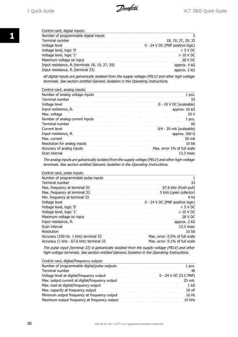
Control card, digital inputs:Number of programmable digital inputs 5Terminal number 18, 19, 27, 29, 33Voltage level 0 - 24 V DC (PNP positive logic)Voltage level, logic '0' < 5 V DCVoltage level, logic '1' > 10 V DCMaximum voltage on input 28 V DCInput resistance, Ri (terminals 18, 19, 27, 29) approx. 4 kΩInput resistance, Ri (terminal 33) approx. 2 kΩ
All digital inputs are galvanically isolated from the supply voltage (PELV) and other high-voltageterminals. See section entitled Galvanic Isolation in the Operating Instructions.
Control card, analog inputs:Number of analog voltage inputs 1 pcs.Terminal number 53Voltage level 0 - 10 V DC (scaleable)Input resistance, Ri approx. 10 kΩMax. voltage 20 VNumber of analog current inputs 1 pcs.Terminal number 60Current level 0/4 - 20 mA (scaleable)Input resistance, Ri approx. 300 ΩMax. current 30 mAResolution for analog inputs 10 bitAccuracy of analog inputs Max. error 1% of full scaleScan interval 13.3 msec
The analog inputs are galvanically isolated from the supply voltage (PELV) and other high-voltageterminals. See section entitled Galvanic Isolation in the Operating Instructions.
Control card, pulse inputs:Number of programmable pulse inputs 1Terminal number 33Max. frequency at terminal 33 67.6 kHz (Push-pull)Max. frequency at terminal 33 5 kHz (open collector)Min. frequency at terminal 33 4 HzVoltage level 0 - 24 V DC (PNP positive logic)Voltage level, logic '0' < 5 V DCVoltage level, logic '1' > 10 V DCMaximum voltage on input 28 V DCInput resistance, Ri approx. 2 kΩScan interval 13.3 msecResolution 10 bitAccuracy (100 Hz- 1 kHz) terminal 33 Max. error: 0.5% of full scaleAccuracy (1 kHz - 67.6 kHz) terminal 33 Max. error: 0.1% of full scale
The pulse input (terminal 33) is galvanically isolated from the supply voltage (PELV) and otherhigh-voltage terminals. See section entitled Galvanic Isolation in the Operating Instructions.
Control card, digital/frequency output:Number of programmable digital/pulse outputs 1 pcs.Terminal number 46Voltage level at digital/frequency output 0 - 24 V DC (O.C PNP)Max. output current at digital/frequency output 25 mA.Max. load at digital/frequency output 1 kΩMax. capacity at frequency output 10 nFMinimum output frequency at frequency output 16 HzMaximum output frequency at frequency output 10 kHz
1 Quick Guide VLT 2800 Quick Guide
30 MG.28.M1.02 - VLT® is a registered Danfoss trademark
1

Accuracy on frequency output Max. error: 0.2 % of full scaleResolution on frequency output 10 bit
The digital output is galvanically isolated from the supply voltage (PELV) and other high-voltageterminals. See section entitled Galvanic Isolation in the Operating Instructions.
Control card, analog output:Number of programmable analog outputs 1Terminal number 42Current range at analog output 0/4 - 20 mAMax. load to common at analog output 500 ΩAccuracy on analog output Max. error: 1.5 % of full scaleResolution on analog output 10 bit
The analog output is galvanically isolated from the supply voltage (PELV) and other high-voltageterminals. See section entitled Galvanic Isolation in the Operating Instructions.
Control card, 24 V DC output:Terminal number 12Max. load 130 mA
The 24 V DC supply is galvanically isolated from the supply voltage (PELV) , but has the samepotential as the analogue and digital inputs and outputs. See section entitled Galvanic Isolationin the Operating Instructions.
Control card, 10 V DC output:Terminal number 50Output voltage 10.5 V ±0.5 VMax. load 15 mA
The 10 V DC supply is galvanically isolated from the supply voltage (PELV) and other high-voltageterminals. See section entitled Galvanic Isolation in the Operating Instructions.
Control card, RS 485 serial communication:Terminal number 68 (TX+, RX+), 69 (TX-, RX-)Terminal number 67 + 5 VTerminal number 70 Common for terminals 67, 68 and 69
Full galvanic isolation. See section entitled Galvanic Isolation in the Operating Instructions.For CANopen/DeviceNet units, see VLT 2800 DeviceNet manual, MG.90.BX.YY.
Relay outputs:1)
Number of programmable relay outputs 1Terminal number, control card (resisitvie and inductive load) 1-3 (break), 1-2 (make)Max. terminal load (AC1) on 1-3, 1-2, control card 250 V AC, 2 A, 500 VAMax. terminal load (DC1 (IEC 947)) on 1-3, 1-2, control card 25 V DC, 2 A /50 V DC, 1A, 50WMin. terminal load (AC/DC) on 1-3, 1-2, control card 24 V DC 10 mA, 24 V AC 100 mA
The relay contact is separated from the rest of the circuit by strengthened isolation.
Note: Rated values resistive load - cosΦ >0.8 for up to 300,000 operations.Inductive loads at cosΦ 0.25 approximately 50% load or 50% life time.
Cable lengths and cross sections:Max. motor cable length, screened/armoured cable 40 mMax. motor cable length, unscreened/unarmoured cable 75 mMax. motor cable length, screened/armoured cable and motor coil 100 mMax. motor cable length, unscreened/unarmoured cable and motor coil 200 mMax. motor cable length, screened/armoured cable and RFI/1B filter 200 V, 100 mMax. motor cable length, screened/armoured cable and RFI/1B filter 400 V, 25 mMax. motor cable length, screened/armoured cable and RFI 1B/LC filter 400 V, 25 m
Max. cross section to motor, see next section.
VLT 2800 Quick Guide 1 Quick Guide
MG.28.M1.02 - VLT® is a registered Danfoss trademark 31
1
Max. cross section to control wires, rigid wire 1.5 mm2/16 AWG (2 x 0.75 mm2)Max. cross section to control cables, flexible cable 1 mm2/18 AWGMax. cross section to control cables, cable with enclosed core 0.5 mm2/20 AWG
When complying with EN 55011 1A and EN 55011 1B the motor cable must in certaininstances be reduced. See EMC emission.
Control characteristics:Frequency range 0.2 - 132 Hz, 1 - 1000 HzResolution of output frequency 0.013 Hz, 0.2 - 1000 HzRepeat accuracy of Precise start/stop(terminals 18, 19) ± 0.5 msecSystem response time (terminals 18, 19, 27, 29, 33) 26.6 msecSpeed control range (open loop) 1:10 of synchronous speedSpeed control range (closed loop) 1:120 of synchronous speedSpeed accuracy (open loop) 150 - 3600 rpm: Max. error of ±23 rpmSpeed accuracy (closed loop) 30 - 3600 rpm: Max. error of ±7.5 rpm
All control characteristics are based on a 4-pole asynchronous motor
Surroundings:Enclosure IP 20Enclosure with options NEMA 1Vibration test 0.7 gMax. relative humidity 5% - 93% during operationAmbient temperature Max. 45 °C (24-hour average max. 40 °C)
Derating for high ambient temperature, see special conditions in the Design Guide
Min. ambient temperature during full-scale operation 0 °CMin. ambient temperature at reduced performance - 10 °CTemperature during storage/transport -25 - +65/70 °CMax. altitude above sea level 1000 m
Derating for high air pressure, see special conditions in the Design Guide
EMC standards, Emission EN 61000-6-4, EN 61800-3, EN 55011
EMC standards, ImmunityEN 61000-6-1/2, EN 61000-4-2, EN 61000-4-3, EN 61000-4-4, EN
61000-4-5, EN 61000-4-6, EN 61800-3
See section on special conditions in the Design Guide
Safeguards:
• Electronic thermal motor protection against overload.
• Temperature monitoring of the power module ensures that the frequency converter cutsout if the temperature reaches 100 °C. An overload temperature cannot be reset untilthe temperature of the power module is below 70 °C.
1.12 Special Conditions1.12.1 Aggressive Environments
The frequency converter is not to be installed in environments, where liquids, par-ticles or gases are in the air that would impact and damage the electronics. Unlessthe necessary measures are taken to protect the frequency converter, there is a riskof stoppages, which reduce the service life of the frequency converter.
Aggressive gases, such as sulphur, nitrogen and chlorine compounds, together with high humidityand temperature, facilitate possible chemical processes on the components of the frequency con-verter. These chemical processes quickly impact and damage the electronics. In these areas,
1 Quick Guide VLT 2800 Quick Guide
32 MG.28.M1.02 - VLT® is a registered Danfoss trademark
1
cabinet fitting with fresh-air circulation in the cabinet is recommended, thereby ensuring thataggressive gases are kept away from the frequency converter.
NB!Fitting of frequency converters in aggressive environments increases the risk ofstoppages, in addition to considerably reducing the service life of the unit.
Before the frequency converter is installed, it must be checked whether there are liquids, particlesor gases in the air. This can be done by looking at existing installations in the same environment.Typical indicators of harmful airborne liquids are water or oil on metal parts or corrosion of metalparts. Too many dust particles are typically observed on top of installation cabinets and on existingelectrical installations. Indicators that there are aggressive gases in the air are copper rails andcable ends that are black on existing electrical installations.
1.12.2 Derating for Ambient Temperature
The ambient temperature measured over 24 hours should be at least 5° C lower than the max.ambient temperature.If the frequency converter is operated above 45° C, the continuous output current should bedecreased.
1.12.3 Derating for Low Air Pressure
Above 1000 m the ambient temperature or max. output current must be derated.For altitudes above 2000 m, please contact Danfoss regarding PELV.
1.12.4 Derating for Running at Low Speeds
When a motor is connected to at frequency converter, it is necessary to check that the cooling ofthe motor is adequate.A problem may occur at low speeds in constant torque applications. Running continuously at lowspeeds – below half the nominal motor speed – may require additional air cooling. Alternatively,choose a larger motor (one size up).
1.12.5 Derating for Long Motor Cables
The frequency converter has been tested using a 75 m unscreened/unarmoured cable and a 25m screened/armoured cable and has been designed to work using a motor cable with a ratedcross-section. If a cable with a larger cross-section is required, it is recommended to reduce theoutput current by 5% for each step the cable cross-section is increased. (Increased cable cross-section leads to increased capacitance to earth, and thus to an increased earth leakage current).
1.12.6 Derating for High Switch Frequency
The frequency converter will automatically derate the rated output current IVLT,N, when the switch-ing frequency exceeds 4.5 kHz.In both cases, the reduction is carried out linearly, down to 60% of IVLT,N.
VLT 2800 Quick Guide 1 Quick Guide
MG.28.M1.02 - VLT® is a registered Danfoss trademark 33
1