1100-series deployment guide - zendesk...5 screenbeam 1100-series deployment guide v1.0 recommended...
TRANSCRIPT

1100-Series
Deployment Guide
Version 1.0

This document is copyright © 2019 Actiontec Electronics, Inc.. All rights reserved. Use of this document
is governed by the terms and conditions outlined at http://www.actiontec.com/terms-of-use/.
Actiontec products and associated software may contain and/or use open source software. Please see
http://opensource.actiontec.com/ for pertinent open source information.
Actiontec product warranty information may be found on the corresponding product webpages at
http://www.actiontec.com.
Actiontec, ScreenBeam, ScreenBeam 1100, the Actiontec logo and the ScreenBeam logo are either
trademarks or registered trademarks of Actiontec Electronics Inc. in the United States of America and/or
other countries. Miracast and Wi-Fi are trademarks or registered trademarks of the Wi-Fi Alliance in the
United States of America and/or other countries. IEEE is a trademark or registered trademark of the
Institute for Electrical and Electronics Engineers, Inc. in the United States of America and/or other countries.
Ethernet is a trademark or registered trademark of Xerox Corp. in the United States of America and/or other
countries. TIA is a trademark or registered trademark of the Telecommunications Industry Association in
the United States of America and/or other countries. Microsoft and Windows are either trademarks or
registered trademarks of Microsoft Corporation in the United States of America and/or other countries.
macOS, iOS, Mac and OSX are either trademarks or registered trademarks of Apple Inc. in the United States
of America and/or other countries. Android, Google and YouTube are either trademarks or registered
trademarks of Alphabet, Inc. and/or its subsidiaries in the United States of America and/or other countries.
HDMI and the HDMI logo are trademarks or registered trademarks of HDMI Licensing, LLC in the United
States of America and/or other countries. Intel, Core i3 and Core i5 are either trademarks or registered
trademarks of Intel Corp. in the United States of America and/or other countries. AMD is a trademark or
registered trademark of Advanced Micro Devices, Inc. in the United States of America and/or other countries.
All other trade names, trademarks or registered trademarks in this document are used with reference to the
entities claiming those marks and/or the names of their products in the United States of America and/or other
countries, and Actiontec Electronics Inc. does not claim any proprietary interest in the rights or marks of
others.
Actiontec Electronics Inc. is not responsible for nor makes any express or implied guarantee regarding the
accuracy of the contents of this document, nor any third-party products or standards referred to in this
document.

Table of Contents
Introduction ............................................................................................................................. 4
Key Features ................................................................................................................... 4
System Requirements ..................................................................................................... 4
Related Documents ......................................................................................................... 6
Setting up Receiver using CMS ............................................................................................. 7
Configuration – Isolation vs. Network ..................................................................................... 8
Fully-Isolated Configuration .......................................................................................... 10
Network-connected Configuration ................................................................................. 12
Network Configuration Matrix ........................................................................................ 14
Configure the Infrastructure Network ................................................................................... 16
Ethernet Network........................................................................................................... 16
Wireless Network .......................................................................................................... 17
Connecting Receiver to Infrastructure Network ............................................................ 18
Connecting Client Device to Infrastructure Network ..................................................... 18
iOS/macOS Native Screen Mirroring ................................................................................... 19
Introduction .................................................................................................................... 19
macOS Native Screen Mirroring ................................................................................... 19
iOS Native Screen Mirroring ......................................................................................... 21

© 2019 Actiontec Electronics Inc. All rights reserved. 4 ScreenBeam 1100-Series Deployment Guide v1.0
Introduction
The ScreenBeam 1100 wireless collaboration solution brings native wireless display to all
modern operating systems, including support for extended desktop in Windows 10 and
macOS and wireless touch and inking in Windows 10. ScreenBeam 1100 allows for an
optimal experience in installation, deployment, management, and end-user satisfaction with
dual independent Wi-Fi radios and gigabit Ethernet connectivity. Miracast P2P for Windows
and Android, Miracast Infrastructure mode for Windows 10 and iOS/macOS Screen Mirroring
for Apple devices is built into ScreenBeam 1100. The information contained in this
document outlines the general features, requirements and recommendations for presentation
scenarios for ScreenBeam 1100. For instructions on connection via native mirroring for
Windows 10/8.1, Android, iOS and macOS, please visit http://www.screenbeam.com/setup .
Key Features
Key features of ScreenBeam 1100 include:
⚫ Native wireless display with extended desktop on all modern operating systems
⚫ 802.11ac 3x3 MIMO Wi-Fi for simultaneous P2P and local Wi-Fi mode device access
⚫ 802.11ac 2x2 MIMO Wi-Fi and gigabit Ethernet for dual network connection support
⚫ Secured user connection with PIN to limit access to authorized display sources
⚫ USB 3.0 and dual USB 2.0 for peripherals and upgrades
⚫ 4K HDMI video out with HDCP wireless protected content playback
⚫ VGA out for projectors and legacy display devices
⚫ Analog line audio out for external audio amplification or capture
System Requirements
Minimum and recommended system requirements for deployment of ScreenBeam 1100 are
as follows.
Minimum – Native Playback
• OS: MS Windows 8.1 or later, macOS 10.10 or later, iOS 11 or later, and Android 4.2 or
later with Miracast
• CPU: 4th Gen Intel Core i3 or AMD equivalent (Windows/macOS)
• Wi-Fi: 802.11n or 802.11ac Dual-Band 2x2
• RAM: 4GB
• HDD free space: 50GB

© 2019 Actiontec Electronics Inc. All rights reserved. 5 ScreenBeam 1100-Series Deployment Guide v1.0
Recommended – Native Playback
• OS: MS Windows 10 or later, and 2012 or newer Macs running macOS 10.10 or later
• CPU: 5th Gen Intel Core i5 or AMD equivalent, or later
• Wi-Fi: Intel Dual-Band Wireless AC 826x (or later)
• RAM: 8GB
• HDD free space: 50GB (or more)
ScreenBeam Firmware
ScreenBeam 1100 receiver with firmware 11.0.1.0 (or later)
Network Requirements
No network is required for ScreenBeam 1100 to function due to its built-in local Wi-Fi mode
and Miracast P2P.
If a network connection is needed for a specific configuration, the following minimums
apply:
• IEEE 802.3u / 100BASE-TX compliant 100Mbps Ethernet connection for ScreenBeam
receiver connection – IEEE 802.3ab / 1000BASE-T 1Gbps Ethernet connection is
recommended (for connection via wired Ethernet)
• RJ-45-terminated shielded Cat 5e or better Ethernet cable from switch to ScreenBeam
receiver (for connection via wired Ethernet)
• IEEE 802.11n/ac Wi-Fi connectivity (for connection via wireless bridge and for device
access points – 2.4/5GHz-capable Wi-Fi access point strongly recommended)
• 802.11n/ac Wi-Fi connectivity for client devices (5GHz strongly recommended)
• Required ports:
o macOS: 8554 (TCP), 24030 (UDP), 35507 (TCP)
For native mirroring: 5353 (UDP), 7000 (UDP), 7100 (TCP), 18000-18009
(UDP), 47000(TCP)
o Win 7: 7236 (TCP), 24030 (UDP), 35507 (TCP)
• VLAN routing may be required if ScreenBeam and Client devices are connected to
different VLAN networks
• 25 Mbps peak bandwidth capacity (for 4K wireless display) or 10 Mbps peak bandwidth
capacity (for 1080p display)
Other
• Display with available HDMI or VGA port supporting 720p/WXGA resolution or better
• Display with HDCP 2.2 (for protected content streaming)

© 2019 Actiontec Electronics Inc. All rights reserved. 6 ScreenBeam 1100-Series Deployment Guide v1.0
Related Documents
To better understand the deployment of ScreenBeam Wireless display, and its display
capabilities over LAN, the following documents are recommended for review:
• ScreenBeam Receiver (ScreenBeam 1100) user guide
• ScreenBeam Central Management System user guide
Note: ScreenBeam Central Management System (CMS) is not required for ScreenBeam
Wireless display over LAN, but it is highly recommended for managing ScreenBeam
receivers. See https://www.screenbeam.com/products/screenbeam-cms/ for details.

© 2019 Actiontec Electronics Inc. All rights reserved. 7 ScreenBeam 1100-Series Deployment Guide v1.0
Setting up Receiver
Ensure the ScreenBeam 1100 receiver is updated to the latest firmware version as noted
above. The firmware version is indicated on the Ready to Connect screen at the bottom right
corner. In the example below, the receiver has outdated firmware that will need to be
updated to the latest firmware prior to proceeding.
When setting up multiple receivers, update and setup can be accomplished in three ways:
• Local Management Interface
• USB storage
• ScreenBeam Central Management System
For multi-unit deployments, ScreenBeam Central Management System is recommended to
ensure ease of deployment.
The latest firmware and update instructions may be obtained from the ScreenBeam 1100
support webpage. Refer to the ScreenBeam 1100 user manual, Quick Start Guide or
ScreenBeam Central Management System manual for details on how to update the firmware.

© 2019 Actiontec Electronics Inc. All rights reserved. 8 ScreenBeam 1100-Series Deployment Guide v1.0
Configuration – Isolation vs. Network
The ScreenBeam 1100 is the most flexible wireless collaboration system available with
several network connectivity options for direct and infrastructure connection.
ScreenBeam 1100 can provide two separate connections to network infrastructure in addition
to the Miracast P2P and local Wi-Fi mode connections. The decision to use one or more of
these interfaces is dependent on several factors, including device management policies,
wireless and spectrum management policies, network management policies, the types of
devices to be supported, and whether guests require separate network access.

© 2019 Actiontec Electronics Inc. All rights reserved. 9 ScreenBeam 1100-Series Deployment Guide v1.0
Each of the interfaces is described below:
Interface Connectivity Use
Miracast P2P 802.11ac 3x3 MIMO For Windows 10/8.1 & Android 4.2+ in
Miracast P2P mode only
Note: No external network access available
from this interface to any other interface
Local Wi-Fi Mode 802.11ac 3x3 MIMO For iOS/macOS Screen Mirroring or Windows
10 devices using Miracast Infrastructure mode
connections
Note: External network access can be
optionally connected via Wired Ethernet or
Wireless Bridge interfaces below
Wired Ethernet 1000-BASE-T RJ45 For iOS/macOS Screen Mirroring or Windows
10 devices using Miracast Infrastructure mode
connections via an externally-connected
network with wireless access points for client
devices
Note: Can be configured to isolate or pass
network traffic to and from SB1100 Local Wi-Fi
Mode connected devices, but not to and from
the Wireless Bridge connection
Wireless Bridge 802.11ac 2x2 MIMO For iOS/macOS Screen Mirroring or Windows
10 devices using Miracast Infrastructure mode
connections via an externally-connected
network with wireless access points for client
devices
Note: Can be configured to isolate or pass
network traffic to and from SB1100 Local Wi-Fi
Mode connected devices, but not to and from
the Wired Ethernet connection
ScreenBeam 1100 configurations generally fall into two categories: fully-isolated and
network-connected. The sections below outline the functionality available for both
categories.

© 2019 Actiontec Electronics Inc. All rights reserved. 10 ScreenBeam 1100-Series Deployment Guide v1.0
Fully-Isolated Configuration
A popular configuration for wireless collaboration systems is the fully-isolated mode. Full
isolation is common in organizations that do not allow professional AV equipment attached
to a corporate network for security or policy reasons.
In full isolation, ScreenBeam 1100 provides two direct connections:
• Miracast P2P for Windows 10/8.1 and Android 4.2 and later devices
• Local Wi-Fi mode connections for all supported devices but particularly for iOS 11
and later and macOS 10.10 and later devices.
Full isolation mode is the default configuration for ScreenBeam to facilitate evaluation and
ease of deployment. The dedicated 802.11ac 3x3 MIMO Wi-Fi can be set to a unique name
for the Miracast P2P and Local Wi-Fi that will appear on the display, and can be adjusted for
wireless band, channel and power. It is recommended that the wireless band and channel
selected do not overlap with nearby rooms and Wi-Fi access points for maximum
performance. It is also permissible to have only one of Miracast P2P or local Wi-Fi modes
available, but it is recommended to leave both on to ensure access for all users. Wireless
touch display connection is available for Windows 10 users on either Miracast P2P or local
Wi-Fi mode, but not for iOS, macOS, or legacy app users.
In full isolation mode, users will not have access to Internet or internal network resources
when connected via local Wi-Fi mode except through a mobile hotspot if already built into
the client device. Miracast P2P users, however, will be able to connect simultaneously to a
separate Wi-Fi network and the P2P connection. Any other device connected to the
ScreenBeam 1100, whether on P2P or on local Wi-Fi mode, will be completely isolated from
every P2P device and no network traffic will be able to pass to or from any device connected
via P2P. ScreenBeamcannot be managed remotely using tools such as ScreenBeam

© 2019 Actiontec Electronics Inc. All rights reserved. 11 ScreenBeam 1100-Series Deployment Guide v1.0
Central Management System without network access, so updates and reconfiguration will
have to be conducted manually via USB or the Local Management Interface.

© 2019 Actiontec Electronics Inc. All rights reserved. 12 ScreenBeam 1100-Series Deployment Guide v1.0
Network-connected Configuration
The majority of wireless collaboration systems are connected to one or more enterprise
and/or guest networks. External access points and other networking equipment provide
device access to ScreenBeam, other network resources and Internet access.
Specific deployment requirements will drive variations in the configuration above. In the
example above, guest Miracast access is available via both P2P and Infrastructure on the
guest network to ensure maximum compatibility for Windows 10 devices that have
Infrastructure-mode Miracast and whose wireless card drivers may be sub-optimal, such as
on consumer-grade PCs. Miracast P2P devices would optionally attach to the guest
network if guest Internet access or other guest resources were required. The multiple
networks shown are typically implemented using VLANs using the same physical hardware
rather than separate hardware.
One major concern for network-connected devices is the Bonjour or mDNS broadcast
required to identify the wireless display receiver presence for iOS and macOS devices.
Wireless access point and network equipment vendors often provide mDNS caching features
to preserve discoverability while not impacting network traffic and quality of service. It is
always recommended for ScreenBeam 1100 deployments to take advantage of such features
when available. In cases when mDNS traffic cannot be cached at wireless access points
and switches, sequestering mDNS traffic - while supporting Windows, Android, and Apple
devices on both the employee network and isolated guest network - is possible on
ScreenBeam 1100.

© 2019 Actiontec Electronics Inc. All rights reserved. 13 ScreenBeam 1100-Series Deployment Guide v1.0
In the example above, there are three networks. The enterprise Windows employee
network is not connected to the ScreenBeam, as employees using Windows and Android
devices would connect via Miracast P2P exclusively. The enterprise iOS/macOS employee
network and guest network are connected to the ScreenBeam using Wired Ethernet and
Wireless Bridge connections respectively. The ScreenBeam is configured to connect the
Local Wi-Fi Mode connection to the guest network via the Wireless Bridge. Assuming
mDNS is blocked at the guest network access points and enterprise Windows employee
network access points, only iOS and macOS devices and their resources can be exposed to
the broadcasts, making network traffic management easier. The enterprise iOS/macOS
employee network above will typically require additional routing to resources common to both
Windows/Android devices and iOS/macOS devices, but all mDNS traffic is easily blocked
from passing into the enterprise Windows employee network at the router to maintain overall
network performance.
A variation on the above configuration is if Local Wi-Fi Mode is undesirable and it is
acceptable to allow mDNS traffic only on the guest network. In such cases, all guest devices
would connect to the ScreenBeam via guest network through the Wireless Bridge.

© 2019 Actiontec Electronics Inc. All rights reserved. 14 ScreenBeam 1100-Series Deployment Guide v1.0
Network Configuration Matrix
For a summary the possibilities for configuring networks on ScreenBeam 1100, please refer
to the matrix table below. The table entries in gray indicate full external network isolation.
Configuration also follows the following conventions:
• Infrastructure-mode Miracast for Windows 10 and iOS/macOS Screen Mirroring can
be optionally disabled if necessary in any configuration. Infrastructure-mode
Miracast is not available on Windows 8.1.
• Depending on the configuration, Windows mirroring may be limited to P2P
(designated “P”) or Infrastructure Miracast (designated “I”).
• Android devices can only connect via P2P.
• Dual external network support as noted below is typically guest and employee
networks; however; this can also be configured for dual employee networks to
separate iOS/macOS approved devices from the rest of the network.
• For configurations with dual network and P2P, three external networks can be
supported by devices when Windows/Android devices connect simultaneously to a
separate external network not connected to ScreenBeam and via P2P for wireless
presentation and collaboration. In this way, two employee and one guest network
can be supported.
• The Local Wi-Fi mode connection can be used to block mDNS requests, such as
from guest iOS/macOS devices, when mDNS is blocked at the port connected to the
external network switch while providing a bridge to the external network for other
services.
• Touch capability is available only on Windows 10 devices, and either P2P or a low-
latency network is necessary to enable this.
• By default, all connections to ScreenBeam are fully isolated from one another and
traffic cannot be routed or bridged between them unless otherwise specified. Local
Wi-Fi connected devices can, however, be connected to one of either Wireless Bridge
or Wired Ethernet connections, and can act as a guest network connection if
necessary.

© 2019 Actiontec Electronics Inc. All rights reserved. 15 ScreenBeam 1100-Series Deployment Guide v1.0
Enabled
Interfaces
Devices That
Can Connect Comments
Mir
ac
as
t P
2P
Lo
ca
l W
i-F
i M
od
e
Wir
ed
Eth
ern
et
Wir
ele
ss
Bri
dg
e
Win
do
ws
An
dro
id
iOS
/ma
cO
S
✓ P ✓
✓ ✓ ✓
✓ ✓ ✓
✓
✓
Windows/Android P2P, Windows 10
Infrastructure Miracast & iOS/macOS (Default
receiver configuration)
✓ ✓
Requires external network connection to devices
✓ ✓ ✓ ✓
✓
Requires external network connection to devices
✓ ✓ I ✓
Requires external network connection to devices
Limiting iOS/macOS to local Wi-Fi mode
connection blocks mDNS on external network
✓ ✓ ✓ ✓ ✓ ✓ Requires external network connection to devices
✓ I ✓ Requires external network connection to devices
✓ ✓ ✓ ✓ ✓ Requires external network connection to devices
✓ ✓ I ✓ Requires external network connection to devices
✓ ✓ ✓ ✓ ✓ ✓ Requires external network connection to devices
✓ ✓ I ✓ Supports dual external networks
✓ ✓ ✓ ✓ ✓ ✓ Supports dual external networks plus a third non-
connected network through Windows/Android
P2P
✓ ✓ ✓ I ✓ Supports dual external networks
✓ ✓ ✓ ✓ ✓ ✓ ✓ Supports dual external networks plus a third non-
connected network through Windows/Android
P2P
P = Miracast P2P Only I = Miracast Infrastructure Only
© 2019 Actiontec Electronics Inc. All rights reserved. 16 ScreenBeam 1100-Series Deployment Guide v1.0
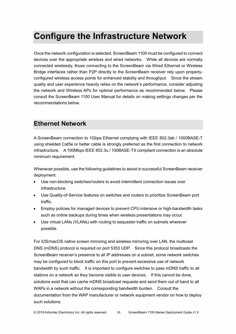
Configure the Infrastructure Network
Once the network configuration is selected, ScreenBeam 1100 must be configured to connect
devices over the appropriate wireless and wired networks. While all devices are normally
connected wirelessly, those connecting to the ScreenBeam via Wired Ethernet or Wireless
Bridge interfaces rather than P2P directly to the ScreenBeam receiver rely upon properly-
configured wireless access points for enhanced stability and throughput. Since the stream
quality and user experience heavily relies on the network’s performance, consider adjusting
the network and Wireless APs for optimal performance as recommended below. Please
consult the ScreenBeam 1100 User Manual for details on making settings changes per the
recommendations below.
Ethernet Network
A ScreenBeam connection to 1Gbps Ethernet complying with IEEE 802.3ab / 1000BASE-T
using shielded Cat5e or better cable is strongly preferred as the first connection to network
infrastructure. A 100Mbps IEEE 802.3u / 100BASE-TX compliant connection is an absolute
minimum requirement.
Whenever possible, use the following guidelines to assist in successful ScreenBeam receiver
deployment:
• Use non-blocking switches/routers to avoid intermittent connection issues over
infrastructure.
• Use Quality-of-Service features on switches and routers to prioritize ScreenBeam port
traffic.
• Employ policies for managed devices to prevent CPU-intensive or high-bandwidth tasks
such as online backups during times when wireless presentations may occur.
• Use virtual LANs (VLANs) with routing to sequester traffic on subnets wherever
possible.
For iOS/macOS native screen mirroring and wireless mirroring over LAN, the multicast
DNS (mDNS) protocol is required on port 5353 UDP. Since this protocol broadcasts the
ScreenBeam receiver’s presence to all IP addresses on a subnet, some network switches
may be configured to block traffic on this port to prevent excessive use of network
bandwidth by such traffic. It is important to configure switches to pass mDNS traffic to all
stations on a network so they become visible to user devices. If this cannot be done,
solutions exist that can cache mDNS broadcast requests and send them out of band to all
WAPs in a network without the corresponding bandwidth burden. Consult the
documentation from the WAP manufacturer or network equipment vendor on how to deploy
such solutions.

© 2019 Actiontec Electronics Inc. All rights reserved. 17 ScreenBeam 1100-Series Deployment Guide v1.0
Wireless Network
802.11ac wireless access points (WAPs) networking is strongly recommended. 802.11n
WAPs are the minimum required for ScreenBeam to work correctly. Dual-band
2.4GHz/5GHz support for WAPs is strongly recommended due to 2.4GHz limitations.
ScreenBeam 1100 supports Dynamic Frequency Selection (DFS) channel only for the
Wireless Bridge, not P2P and Local Wi-Fi connectivity. Dynamic Frequency Selection is
required on certain channels in the 5GHz band so that wireless connection on DFS channels
automatically switches when in use by other applications such as radar. Ensure P2P and
Local Wi-Fi are configured to support non-DFS 5GHz (recommended) and/or 2.4GHz band
as follows:
• 2.4GHz – Channels 1, 6, 11 only
• 5GHz (non-DFS, 20MHz wide channels) – Channels 36, 40, 44, 48, 149, 153, 157,
161 only
• 5GHz (non-DFS, 40MHz wide channels) – Channels 36, 44, 149, 157 only
To avoid connectivity issues, the following practices are strongly recommended:
• Do not use overlapping channels for WAPs in adjacent rooms, including between
floors. Alternating channels use helps ensure reliable connectivity.
• Use 5GHz whenever possible versus 2.4GHz, as 5GHz signals cannot penetrate
through walls to adjacent rooms as well as 2.4GHz signals can, and 2.4GHz is
used by more types of devices than 5GHz.
• Minimize use of unauthorized or unmanaged wireless devices by policy (e.g.
Bluetooth, wireless game controllers, wireless video cameras), especially those
using the 2.4GHz band.
• Avoid use of 802.11n for clients and WAPs whenever possible, as 802.11ac is more
spectrum efficient than 802.11n and will give a better presentation experience.
If connectivity issues persist, contact a qualified IT professional to conduct a wireless
survey for recommendations on improving Wi-Fi connectivity.
As discussed above, network switches may not pass mDNS traffic across the network and
block that traffic at switches and routers. If unblocking the port is not feasible, solutions
exist that can cache mDNS broadcast requests and send them out of band to all WAPs in a
network without the corresponding bandwidth burden. Consult the documentation from
the WAP manufacturer or network vendor on how to deploy such solutions.
If such solutions are not available, the devices generating and using mDNS traffic must be
sequestered using one of the ScreenBeam 1100’s interfaces.

© 2019 Actiontec Electronics Inc. All rights reserved. 18 ScreenBeam 1100-Series Deployment Guide v1.0
Connecting Receiver to Infrastructure Network
ScreenBeam 1100 receivers can be connected to the network over both wireless and wired
Ethernet. If only one network connection is used, wired Ethernet is preferable for stability
and optimal experience. Where wired Ethernet connections are unavailable, the wireless
bridge functionality can also be deployed on separate VLANs provided the 2 VLANs are
configured for the client device to communicate with the receiver.
Note: ScreenBeam 1100 receivers behind a Network Address Translated (NATed) router will
not work. Traffic must be explicitly routed between networks.
If total isolation from a wired network is required, such as a guest network / room in a
business, ScreenBeam with Miracast P2P and Local Wi-Fi is the ideal solution for nearly all
modern devices and requires no Ethernet or wireless connection. Prior to starting a
presentation session on ScreenBeam 1100, iOS and macOS Screen Mirroring users,
Windows 10 users desiring Infrastructure-mode Miracast connectivity and users desiring
legacy device support (e.g. Windows 7) must connect either using Local Wi-Fi mode or via
a sequestered WAP and router on the Wired Ethernet or Wireless Bridge connection.
Connecting Client Device to Infrastructure Network
Connect the client device to the same network where the receiver is connected. This means
the WAP, LAN/VLAN and ScreenBeam must be able to see each other. Ensure the source
device gets a good connection to the AP. The recommended connection signal strength
should be good to excellent, i.e. beyond -50dBm (RSSI level).
Ensure the client device and receiver have a low latency by pinging the ScreenBeam from a
device in the desired connection scenario. A network ping response time under 10ms is
desirable to ensure excellent end-user wireless presentation experiences.
The IP address of ScreenBeam 1100 receiver is displayed by default on the Ready to
Connect screen. The IP address display can be enabled or disabled using either CMS or
the ScreenBeam 1100’s management console and setting the “Show network information on
the TV screen” option to Enable.

© 2019 Actiontec Electronics Inc. All rights reserved. 19 ScreenBeam 1100-Series Deployment Guide v1.0
iOS/macOS Native Screen Mirroring
Introduction
ScreenBeam 1100 offers support for native iOS/macOS Screen Mirroring. This feature
allows iOS 11 and later devices, and macOS 10.10 and later devices produced from 2012
onward, to use wireless screen display without needing any apps. Unlike Windows 10/8.1
native screen mirroring, which use Miracast P2P mode direct connections, iOS/macOS
native screen mirroring requires the use of existing WAPs and other network infrastructure
to mirror the user device on the front-of-room display.
Please note the requirements for mDNS broadcast as outlined in the section on Infrastructure
Network Configuration above, as well as the need for the iOS or macOS device to be on the
same network as the ScreenBeam device. If mDNS broadcast traffic is blocked on a
network, or if the ScreenBeam device is inaccessible from the network that the iOS or macOS
device is on, iOS/macOS native screen mirroring will not work.
macOS Native Screen Mirroring
To initiate macOS native Screen Mirroring:
1) Ensure that the Mac is connected to the same network that the ScreenBeam is
connected to.
2) On the Menu bar, click on the Screen Mirroring icon, which is a small square with a
triangle at the bottom. A menu will pop up with several options as follows:
The default option is to mirror the screen directly, but extended desktop can be
chosen by clicking the “Use as Separate Display” option.

© 2019 Actiontec Electronics Inc. All rights reserved. 20 ScreenBeam 1100-Series Deployment Guide v1.0
3) Click on the name of the ScreenBeam receiver at the front of the room from the list
of receivers to connect.
4) If the PIN option is enabled on the ScreenBeam, a dialog box will appear asking for
the PIN:
Enter the corresponding PIN (displayed on the screen) and click Ok.
5) The macOS device will begin mirroring to the front-of-room display.
6) To disconnect from the ScreenBeam, click on the screen mirroring icon again and
click on Off to turn native screen mirroring off. The macOS device will stop mirroring
to the front-of-room display.

© 2019 Actiontec Electronics Inc. All rights reserved. 21 ScreenBeam 1100-Series Deployment Guide v1.0
iOS Native Screen Mirroring
To initiate iOS native screen mirroring:
1) Bring up the Control Center by swiping downward from the upper right corner of the
screen (or upward from the bottom of the screen in older iOS versions), then tap on
the Screen Mirroring button:
2) A list of receivers will be displayed on the screen. Select the ScreenBeam receiver
to present to by tapping on the receiver name:
© 2019 Actiontec Electronics Inc. All rights reserved. 22 ScreenBeam 1100-Series Deployment Guide v1.0
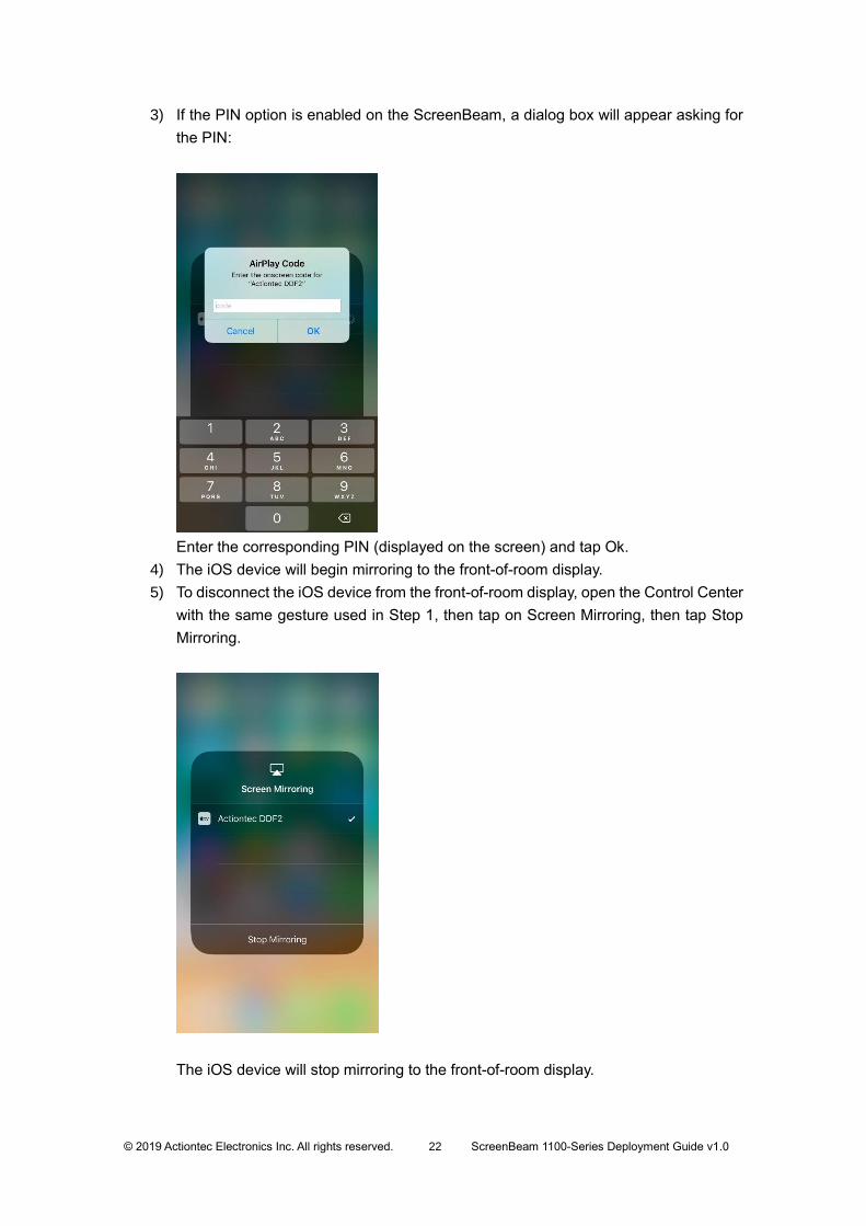
3) If the PIN option is enabled on the ScreenBeam, a dialog box will appear asking for
the PIN:
Enter the corresponding PIN (displayed on the screen) and tap Ok.
4) The iOS device will begin mirroring to the front-of-room display.
5) To disconnect the iOS device from the front-of-room display, open the Control Center
with the same gesture used in Step 1, then tap on Screen Mirroring, then tap Stop
Mirroring.
The iOS device will stop mirroring to the front-of-room display.