1111~iiloollll~rrnmi~fl~i~i~~iii~ - dtic
TRANSCRIPT

NATIONAL ADVISORY COMMITTEEFOR AERONAUTICS
t\,..
j i ...
1111~iIlOOllll~Rrnmi~fl~I~I~~III~3 1176 00509 4090
.,;.
TECHNICAL NOTE
No. 1088
,,t.
l..
THERMODYNAMIC CH.ARrS FOB THE CCNPUva!IOB OF CCHnlSTIOB
.Am> MIX'rURE~ AT. CONSTAm! PRESSUBE
'By L. Richard Turner and Albert M. lord
Aircraft Eng1ne Research LaboratoryCleveland, Ohio.
il-:'. _._
i:, ,. -':-J.~ '; ~~.'- Ii
;'1 i"Gll l b. ,. , .. ,;L. l:.iltii{ATOHVL~.:i.-_ (, E~CA
LA.!'\QLE."i 1-1i::LD, VIRGINIA
1r;,,.
l ' ~.' r::'
WashiDgtonJune 1946

•
NATIONAL ADVISeRY COMMITTEE FOR AERONAUTICS
TECHNICAL NOTE NO. 1086
TEEBMODYNAlIJ.IC CE:.ARTS FOR TEE COMPUTATION OF COMBUSTION
AND 1.rrxTtJBE TEMPEBATUBES AT CONSTANr P:BESS'UBE
By L. 'Richard Turner and Alberl M. Lord
SUMMARY,"
Charts are presented for calculating the combustion tempera-tures and the temperature changes involved in constant-pressurethermodynamic processes of air ~~d the products of combustion ofair and hydrocarbon fuels. Examplos are given in which the chartsare applied to the calculation of the quantity of fuel required forcombustion to a given teIllJ?erature, the increase in tile tem.peratureof products of combustion by the introduction and combustion o~
additional fuel, the change in enthalpy of the products of combustion with change in temperature, the equilibri~ temperatureresulting from the mixing of two gases representine products ofcombustion, and the temperature resulting from the afterburning ofric:ler-than-stoichiometric exhaust gases with additional air. Thecharts are applicable only to prooesses in vThich the final fuel-airratio is leaner th~~ stoichiometric and at temperatures where dissociation is unimportant. They may be applied to steady-state f'lowprocesses.
INrRODUCTION
The accurate calculation of the change in energy of a fluid asits temperature or composition 1s changed is difficult especiallywhen the range of temperature variation is large. Calculations ofthis type arise in connection with the phenomena of combustion,afterburning of rich-mixture exhaust gas, and the miXing of air andcombustion gases. Because of t:t.e -c.ifficulties 1mposed by the useof exact specific heats, many approximations have been used apd insome cases these api;lroxilnations have led to large errors.
Graphical methods of solving prOblems that involve a change inthe heat content of air or the products of combustion of air andhydrocarbon fuels at constant pr~sure have been devised at the NhCACleveland laboratory. Because the total temperature of a gas 1s adirect measure of its total energy content, the charts rJay be used
/'
s KACA TN No. 1066 m
li .
for any steady-state flow process by using the total temperatures of the fluid. The charts are aPplied in this report, by means of examples, to the calculation of the quantity of fuel required for combustion to a given temperature, the increase in temperature of products of combustion by the introduction and burning of aSi- tional fuel, the change in the enthalpy of a burned mixture with a change in temperature, the equilibrium temperature reaultizg from the mixing of two gases each of which is the product of combcstion, and the temperature resulting from the af'terburning of richer-than- stoichiometric exhaust gases with air.
cP
cPf
ec
f
F
f'
H
ha
Ea
hb
hbr
hC
(hC)eff
molal specific heat at constant Pressure, (Btrl)/(lb mol,~)(~R>
specific heat at con&ant pressure of fuel, (Btu)/(lb) (OR)
lower internal energy of combustion of fuel, (Btu)/(lb)
fuel-air ratio
mean fuel-air ratio of mixture
chart fuel-air ratio; fUnCtiOn of Ta and Tb
moial entbalpy of gas, (Btu)/(lb mole)
enthalpy of air, (Btu)/(lb)
mean value of enthalpy of air mixture, (Btu)/(lb of mixture)
enthalpy of leaner-than-stoichiome'cric burned mixture of fuel and aiY, (Btu)/(lb)
sensible enthalpy of richer-than-stoichiometric exhaust gas excluding energy of chemical organization, (Btu)/(ib)
lower enthalpy of combustion of fuel, (Btu)/(lb)
effective lower enthalpy of combustion of fuel in richer- than-stoichiometric exhaust gas, (Btu)/(lb)
2
e
- PWA TN No. 1086
i s -hcheq
. J
.
II:
Itm
K, m 2
R
Ra
%
r
T
Ta
'a
r,
Te
Ti
'f
enthalpy available through combustion tith excess air of 1 + f pounds of richer-than-StoichLometric exhaust gas, (Btu)/(lb)
mechanical equivalent of heat, (778 ft-lb)/(Btu)
correction factor tc chawe in total enthalpy of richer- t&an-stoichiometric exhaust gas with changes fn fez+ perature for change3 in fuel-air ratio and hydragen- carbon ratio of fuel
correction factor to fuel-air ratio for chexge in lo?rer 0nthalp,T~ of combrstzon of fuel
correction factor to fuel-air ratio for change in h.ydrogen-carbon ratio of fuel
molecular weight of air, 28.972 (lb)/(lb mole)
hydrogen-carbon ratio of fuel
pressure (lb)/bq ft) universal gas constant, X$45.7 (ft-lb)/(lb molc)("R)
gas constant for air, 53.352 (f-t-lb)/(lb)('R)
gas constant of burned mixture of fuel and air, (ft-lb)/(lb)(oR)
ratio of weights of original air in two burned mi,xtures
total temperature, ("R)
total air teqerature, (OR)
total mean temperature of air mixture, (5R)
total temperature of Surned mixkiie, ("R)
total exhaust-gas tezqerature, (OR) '
total initial teqerature, (OR)
total final temperature, (?R)
3

.
‘IC
sa
W
(Oz)a
(Hz)
.
NACA TN No. 1086
reference temperature, (OR)
specific molal volume, (cu ft)/(lb mole)
weight of original air in burned mixture, (lb)
combustion efficiency
total enthalpy of richer-than-stoichiometric exhaust gas referred to enthalpy of air at 540' R as zero of enthalpy
total enthalpy of richer-than-stoicbiometric exhaust gas at 1980° R
concentration of oxygen in air, (mole oxygen)/(inole air)
concentration of hydrogen in exhaust gas, (mole hydrogen)/ (mole of original air)
The subscripts 1, 2, etc. are used alone or in add$tion to any regular subscript to indicate successfve values taken on by a single quantity. For example, Tbl and Tb2 designate, respectively, the temperature of a burned mixture, 'I$, at points 1 and 2.
The subscripts x, y, etc. are used to identify two or more fluids that are to be mixed.
The total tB&finWe temperature attained bye gas in a steady-state flow process when itis brought to rest with the conversion of all Its kinetic energy to thermal -- energy. w
SOURCE OF TEXMODYNAMIC DATA
The specific-heat data used in the preparation of the constant- pressure combustion charts for hydrocarbon fuels and air were taken from reference 1 and extended to higher temperatures by the use of data contained in references 2 to 8. The charts are exact only at temperatures below those at which dissociation becomes ~ortant. In most calculations, dissociation may be neglected for all tem- peratures below about 3200' R. The charts have been extended beyond 3200' R, without, however, considering dissociation, in order that approximate Mlculations may be made with the chart for a higher final temperature.
4

* RACA<TN No, 1086
The charts are based on a reference temperature of gO" R (80.3O F). The heat of combustion of the fuel, therefore, is to be corrected to the basis of the 540' R and to the normal state of the fuel at that temperature before combustion calculations are made, These corrections are discussed in appendix A.
l?RIXXPLJ$ OF TKE CONSTAE-PRESXJRE CCMBUSTION CHARTS
Thermodynamics of constant-pressure combustion. - In order to avoid the use of complicated subscripts the notation
1 2 x -9
is used to mean "the valus of x at z minus the value of x at y."
The lower enthalpy of combustion of a fuel at constant pressure h, is defined as the heat (oh,) removed during the combustion at constant pressure of a mixture of fuel and oxygen when the inLtia1 snd final temperatures are equal and the products of combustion are all in the gaseous phase. The first law of thermodynamics applied to an ideal constant-pressure combustion for loaner-than-stoichiometric mixtures leads to
lTa - haA Tr
j The form of equation (1)
fh, = (1 + f) hb] Tb
(1) Tr
. . and of all subsequent equations implies that ',
k 'I the value of -h, has been corrected by adding to -h, Yae quantity of heat that must be added to the fuel to bring the fuel to its initial
?,,
condition from its standard phase at the reference temperature T, of \
(S ee appendix A.) When this correction has been asplied, it ";is unnecessary to include an explicit term for the condition of the I
-*$,uel in the equations for the conservation of energy. -a
For leaner-than-stoichiometric m%xtures, the term (1 + f) lq, is given by
L
.
‘,.
5 .

N&A TN No. 1086
i
where A=
( lH HH20 - z 02
)I 2.016
B = @co2 - HO,>/= I
(see reference 1, equation (20).) The term t z t in equation (2) accounts for the difference between the enthalpy of the carbon dioxide and water vapor in the burned mixture and the enthalpy of the oxygen removed from the air by their formation.
The substitution of equation (2) in equation (1) yields the following relation:
-jTb haJ
Ta f =
Tb -hc - AntB
1 m+l 'Tr
(3)
Two types of chart have been prepared by the use of equation (3). The first is a.n alinement chart on which the fuel-air ratio is rep- resented by the slope of a line. This chart permits the solution of all problems involving enthalpy changes when dissociation may be neglected but its general use may be inconvellient because a geometric construction or the use of a parallel rule is required to determine the slope of the fuel-air-ratio line.
.
* .
The second set of charts, which have a somewhat limited range of application, show: (a) temperature rise during combustion as a
' function of the fuel-air ratio and initial air temperature; (b) tem- perature rfse during combustion as a function of the fuel-air ratio and the final mixture temperature. These curves have been prepared for a single fuel. Correction factors petit the calculation of the fuel-air ratio for other fuels tith different hydrogen-carbon ratios and lower heating values.
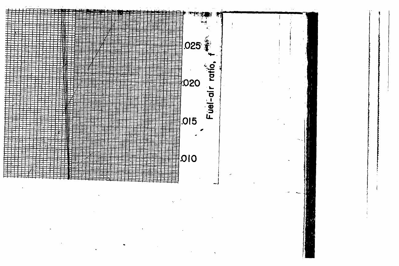
Construction of the constant-pressure alinement chart. - The alinement-type constant-pressure chart is shown in figure 1. The linear scale to the left is the enthalpy of air, which was arbi- trarily taken as zero at 540° R. The horizontal lines marked with a temperature scale are drawn at the ordinate equal to the enthal?y of air at that temperature minus its enthalpy at 540' R. The abscissa is the lower enthalpy of combustion of the fuel h,.
6

NACA TN No. 1086
Along each temperature line the quantity .
1 T Am+B m t 1~
Tr
is laid off to the left of the zero of the abscissa for three values of the hydrogen-carbon ratio m (0.10, 0.15, and 0.20) of the fuel. Thus, vertical lengths on the chart represent quantities in the numerator of equation (3); horizontal lengths represent quantities in the denominator of equation (3).
The values of ha, A, and B are given in table I as functions of the temperature.
USES OFTEECONSTAp\pT-PRESUREALII~~ CEART
Constant-pkessure combustion. - The use of the constant-pressure alinement chart to determine the temperattire attained by an ideal constant-pressure combustion process is illustrated in figfire 2(a) by the following example: -2
*;Initial air temperature Ta,-;?OOo R 'Dinal combustion temperature Tj,, .1860° R ILower enthalpy of combustion b, -18,900 Btu per pound :Hydrogen-carbon ratio of fuel m, 0.175
A line is drawn from the point a (located at Ta = 900' R, hc = -18,900 Btu/lb) to the point b (at the intersection of Yne J.860° R temperature line with the m k O.i75 line (interpolated)). For the purpose of illustration, the right triangle abc is completed, The side bq of the triangle is equal to the term
whfch is the numerator of equation (3), and the side ac of the triangle fs equal to the term
I
L
. .
I Tb -h, - Am+73
n+l TX-
7 ..,

. IJACA TN No. 1086
.
. .
.
which is the denominator of equation (3). The slope of the line ab is therefore proportional to the fuel-air ratio required for the com- bustion. The scales of the,ordinate and the abscissa in figures 1 and 2 have been so chosen tha.t the fuel-air ratio is one-fortieth of the actual geometric slope. Two alternative methods are provided for measuring the slope of line ab; hence the fuel-air ratio:
. .
&Q reference point A (located at ) parallel to the line ab. The fuel- - rsection of t'nis line with the extreme
right-hand fuel-air-ratio scale, The required fuel-air ratlo for the example is 0.0138.
(b) Extend the line ab to the right until it intersects the abscissa of h, lb).
to the right of the zero line at d (hc = -18,900 Btu/ Read the fuel-air ratio f2 opposite this intersection
(0.01828) and the fuel-air ratio fl opposite the ordinate Ta of 900' R (0.00448). The required fuel-air ratio f is the difference be-keen the fuel-air ratios f2 and fl.
f = 0.01823 - 0.00448 = 0.0138
The inverse probla of finding the initial or final temperature, if one temperature and the fuel&air ratio are knoll, is solved in a similar manner except that the slope of the fuel-air ratio line is used to determine the unknown temperature.
Reheating by burning additional fuel. - The method of calcula- tion of the temperature resultfng from bUrni% additionaL fuel in the products of combustion is shown In figure 2(b). Assume th&t the combustion gas of tke example descrfbed in figure 2(a) is cooled to a temperature of 16200 R. Determine the amount of fuel r8qUir8d to raise the temperature of the gas to a temperature of 1900° R by burning additional fuel.
Draw a line from the point a (located at Tb = 1620° R, m = 0.175) with a slope of f = 0.0138 (parallel to a'A) until it intersects the Vertical line for a VtiUe Of he of -18,9CC Btu per pound at b. This potit establishes an initial. temperature, approx- imately 6300 R, compatible with a combustion temperature T-5 of 1620° R and the original fuel-air ratio f of 0.0136. Draw a liae from b to c (located at Tb = 1900' R, m = 0.175) and the parallel line AC', The slope of AC' is the total fuel-air ratio required (0.0183). The required Increment in fllel per po;md of original air f is the difference between these two fuel-air ratios: Af = 0.0183 - 0.0138 = 0.0045.
8

I
‘ XACA TN No. 1086 .
L
.
The increment of fuel. required may also be determined by extending the line6 ab and bc to the second abscissa of hc, using the scale to the right of tine zero line, at d and e, respectively, (at h, = -18,900 Btu/lb). The difference between the ordinates d and e is Af, as indicated on figure 2(b).
Change of enthalpy of a burned mixture with chme in tempera- tUT8. - The use of the constant-pressure alinement chart to deta theheat abstracted from a burned mixture of combustion gases dur-ing a change in temperature is illustrated "Ln figure 2(c) by the followiw example:
Initial temperature Tc, 2600° R Final temperature Tf, 1000° R Fuel-air ratio f, 0.030 Hydrogen-carbon ratio m, 0.175
Locate the points a and b at Ti = 2600' R and Tf = 1000° R on the m = 0.175 line. Draw a line with slope equivalent to f = 0.030 through each point a and b Futersecting the h, = 0 axis at a1 and b', respectively. The required change in enthalpy is the deference betveen the ordinate of a' and b', -469 Btu zer pound of original air or -455.5 Btu ser pound of burned mixture. This result follows immediately from a considera- tion of equation (2). The distance ac in figure 2(c) is equal to
and the distance cd is equal to
1 Tf fkn+B
m + 'JT i
by the construction. The sum of ac and cd is then given by
.
(ac) + (cd) = hajTf + f 2 ; $1; 3. i
= (1 + f) I$JTf aTi
(4)
9

? UACA TB No. 1086 .
. By the construction shown in fi.&re 2(c) the line segment . a'b' = ac + cd because the L.nes aa' and db' are parallel.
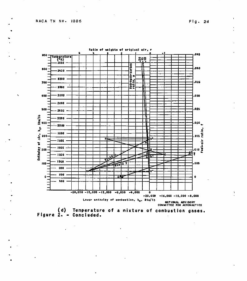
. Temperature of a mixture of combustion gases. - The temgerature
of a mixture of two gases each produced by the combustion of a lean mixture of air and a hydrocarbon fuel may be calculated by the COP- struction shown in figure 2(d). It is assumed that the two fuels have the same hydrogen-carbon ratio. The mixture of the following two gases may be considered as an example.
(a) Fluid x, the products of combustion of 1 pound of air W, with 0.0138 pound of fuel, fx = 0.0138, at a temperature of 1620' R.
(b) Fluid y, the products of combustion for 3 pounds of air with 0.021 ?ound of fuel at a fuel-air ratio fy of 0.007 at
emperaturo of 1200' R.
1
.
The 'hydrogen-carbon ratio of the tw9 fuels ie 0.175.
Draw the line ca' witii thG slope fx = O.Gl38 through the 2oin-b a located at TJ, = 1620' R end w = G.175. ThG point a' Is the intersection of this line with the line h, = 0. Draw thG similar Line cb' through t'ne point b located at Tb = 12CO" R and m = 0.175 with the slop0 fy = O.CO7. Eraw a horizontal line from by to d on the line r = -1 and a horizontal iFno from G' to B on the line r = Way/Wax = 3, w&ra Wa is the weight of original air in each fluid. In order -52 obtain tho greatest possible accuracy the weight ratio r should be ewressGd as a number greater than P. Tho line a*e, corresponding to r 51 must always be drawn to the left from the poi,=lt a* on the h, = 0 ax3.s correqonding to the fluLd having the smaller weight.
Draw the line de, which intersects tho 15nG hc = 0 at g; draw the line gc. The temperature of the gas mixture (1310* R) is found at i where tho line gc intersects the hydrogon-carbon- ratio line at m = 0.175. The slope of the line cg ie equal to thG mGan fuel-air ratio of the mixkure. The mean fuel-air ratio can bo dotermined b,rr drawing the line Ag' parallel to the line cg. The construction just dGscrj.bod solves the problem of doterminir~ the toqerature of tho gas mixture bocsusc the line de di-vidos the vertical line sogmont albf into two segments with long&s propnr- tional to r.
The distance aact is proportioral to fx; the distance b!c' is similarly proportional to fy. Tho distance a%' is then
10

.
. EM!A TN No. 1066 .
. proportional to fx - fy and the distance b'g is therefore pro- portional to (fx - fy)/(l + r). The distance gc' is then ?ropor-
f, - f f, -i- r fy - tiana1to fy -+ 1 + ry = l+r and the slope of the line cg
. corresponds to the mean fuel-air ratio F given by the equation
i;= f, + r fy
1 +r
.
The line cg divfdes any vertical line drawil from .a'c to b'c into segments whose lengths are proportional to r. From the construction illustrated in figure 2(c), the vertical distance from i (Fn fig. 2(d)> to the line ate is proportional to the change in enthalpy of flu'Ld x Zn Btu per pound of ori&-& air;
-similarly the vertical distance from i to the line blc is pro- portional to the change in enthalpy of fluid y. The construction, therefore, satisfies the condition that the change in enthaluy of the fluids shall be equal but opposite in sign when equilzbrium is attained; namely,
p + fx) A%Jjuid x = -r [ (1 + fy) Al3i-j fluid y
because the length of the two se@ents have the ratio r.
Afterburning of richer-than-stoichiometric exhaust gases, - Consideration of the law of the conserva& "ion of energy fields the following equation for the temperature prsduced by the combustion of 1 + f pounds of a ric~~r-than-stoichf3tric exhaust gas with r pounds of air, when the final fuel-air ratio f/(1 + r) is leaner than stoichiometric:
(1 + f) hbr 1
Te lTa = (1 i f + r)
%I -hchem + r ha 1 hb] (5)
0 -rO 0
The value of fuel-ai-r ratio f used Zn equation (5) 'rs the original fuel-air ratio of the richer-tW.n-stoichtometric exhaust gas. From equation (2) the enthalpy of the final mixture at tem- perature 5 is given by the equation
-lTb (1 + f +r> hj,I = (1 + r) 1% ha i
+fAm+B Tb
20 0 1 m+l 0
(6)
11
. I'IACA TN No. 1086 .
.
. 3
When the term ( 1 -I- f + 1') hb 1 is eliminated from 0
equations (5) and (6), the following more convenient form is obtained:
Sa= ha] Tb Tb 'b
Am+B + r ha +f m+l
Tr I Tr I
Tr
where
Tr C? = (i + f) hbr]:" -hchem - haI0 - f t 1 "1
Tr
(7)
(8)
is the total enthalpy of the richer-than-stoichiometric exhaust- gas referred to the enthalpy of air at the reference temperature Tr .as the zero of enthalpy. .
The afterburning calculation may also be treated as the com- bustion of a fuel with the effective lower enthalpy of combustion (hc)eff given by
3 Ta
s;2 - ha
(&Jeff = f Tr
(9)
When the value of &! from equation (9) is substituted in equatfon (7), the relation reduces to
f l+r
3 Tb ha
Ta
1 Tb (10)
JTr
The mean fuel-air ratio ?; for this combustion is gfven by the equation
(11)
where f is the original fuel-air ratio of the richer-than- stoichiometric exhaust gas.
12
m INACA TN No. 1066 I
.
. A derivation of equatio,ns (7) and (8) and the equation for LJ in terms of the thermodynamic properties of the ooqonent gases is given in appendix B.
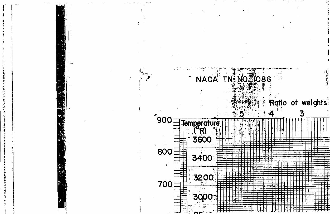
The value of h may be obtained from figure 3 in which a is given as the sum of two numbers w and mW. The change in kl as the temperature is changed is equal to Ilw for a fuel with a hydrogen-carbon ratJ,o of 0.175 at a fuel-air ratio of 0.08. The correction factor K accounts for changes in the hydrogen-carbon ratio and the fuel-air ratio.
The use of the constant-pressure alinement chart to determine the temperature of a mixture of exhaust gas and air with afterburning is illustrated in fQure 4 by the following example: Determine the temperature attained by the afterburning and subsequent mLxing of 1.08 younde of richer-than-stofchiometric exhaust gas, fuel-a;Lr ratio f of 0.08, -hydrogen-carbon ratio m of 0.175, and an ekhaust- gas temperature Te of 1980' R, wfth 2 pounds of air at 411' R. (Note that r =2.)
.
From figure 3, the value of w = 767.5 and RAW= 0. The value of sb is therefore 767.5 Btu per pound of air. The necessary construction is shown in figure 4. The point a' is igcated on the line h, = 0 with the ordinate ha F Sa = 767.5. (It will often be necessary to extend the scale of ordinates beyond 300 Et&b of air.) Born this point, the final temperature is determined exactly as in the case of a mixture of two leaner-than-stoichiometric com- bustion gases.
Draw a line through a' with the sloRe of f equal to the fuel-air ratio of the richer-than-stoichiometric exhaust gas (f = 0.08) intersecting at c the line bc drawn at the air tem- perature T, = 411° R. Rraw a horizontal line from a* to e under r=2. Draw a horizoMM. line from b to the point d at r = -1. Draw the line ed, which intersects ho = 0 at Q. Draw the line cg. The final combustion temperature is found at i where the line cg Intertiects the hydrogen-carbon-ratio line m = 0.175. Tae final-temperature obtained by afterburning and sub- sequent mixing is 1425O R.
The point c is located at the value of the abscissa i;rgual to the mlue of (b)eff given by equation (9), as can be seen from the construction. Th= slope of the line cg corresponds to the mean fuel-air ratio f (equation (11)).
13

.
I NACA TN Ho. 1086
.
. The highest temperature of afterburning that can be calculated with this chart is that for a atoichiometric final mixture. The
.
-
.
.
temperature for burning just to stoichiometric mixture for the example cited is 2560' R (2100 F) and is obtained with approximately 10 yer- cent air at 411' R.
Heat balance of an internal-combustion engine. - The quantity of heat in the exhaust-as of an internal-combustion engine to be used in constructing a heat balance is given by
T 78
for leaner-than-stoichiometric tix-t1rces and by the quantity Ll for richer-than-stoichiometric mixtures. In each case this quantity is the enthalpy per pound of original air In the burned mixture.
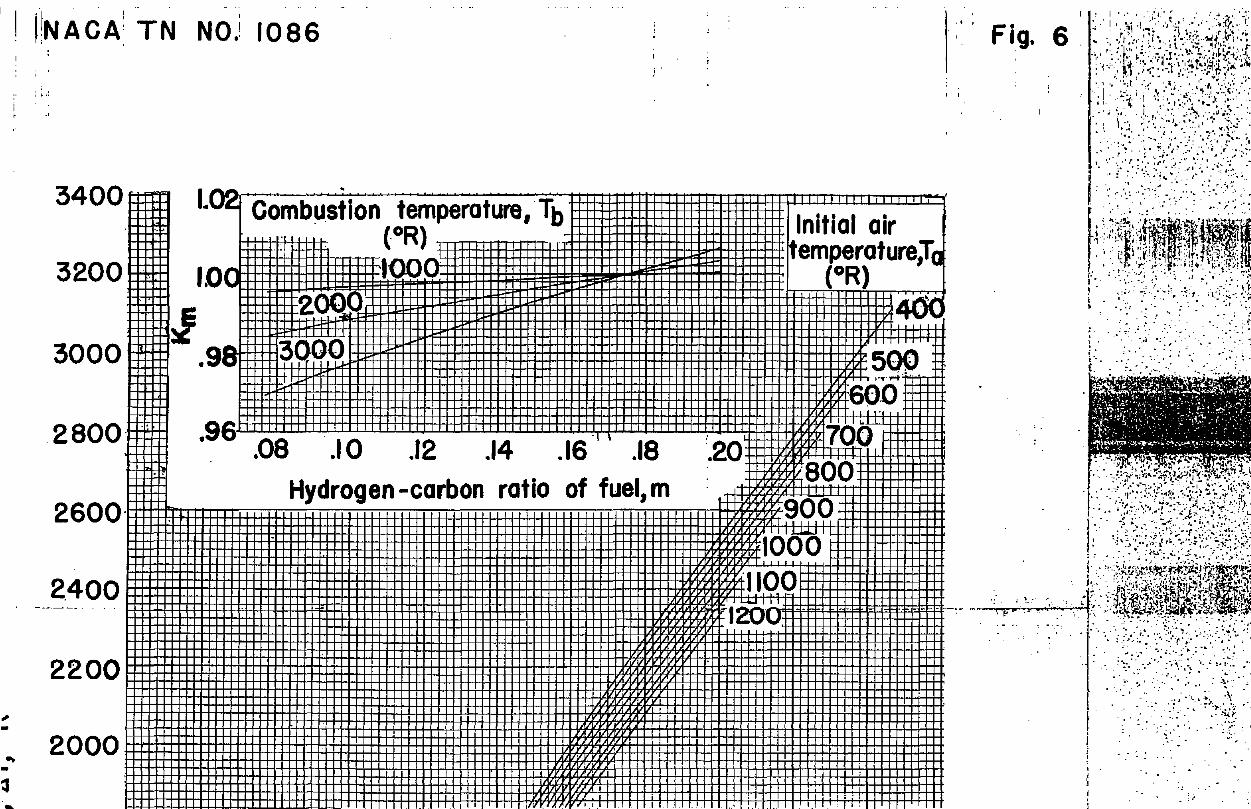
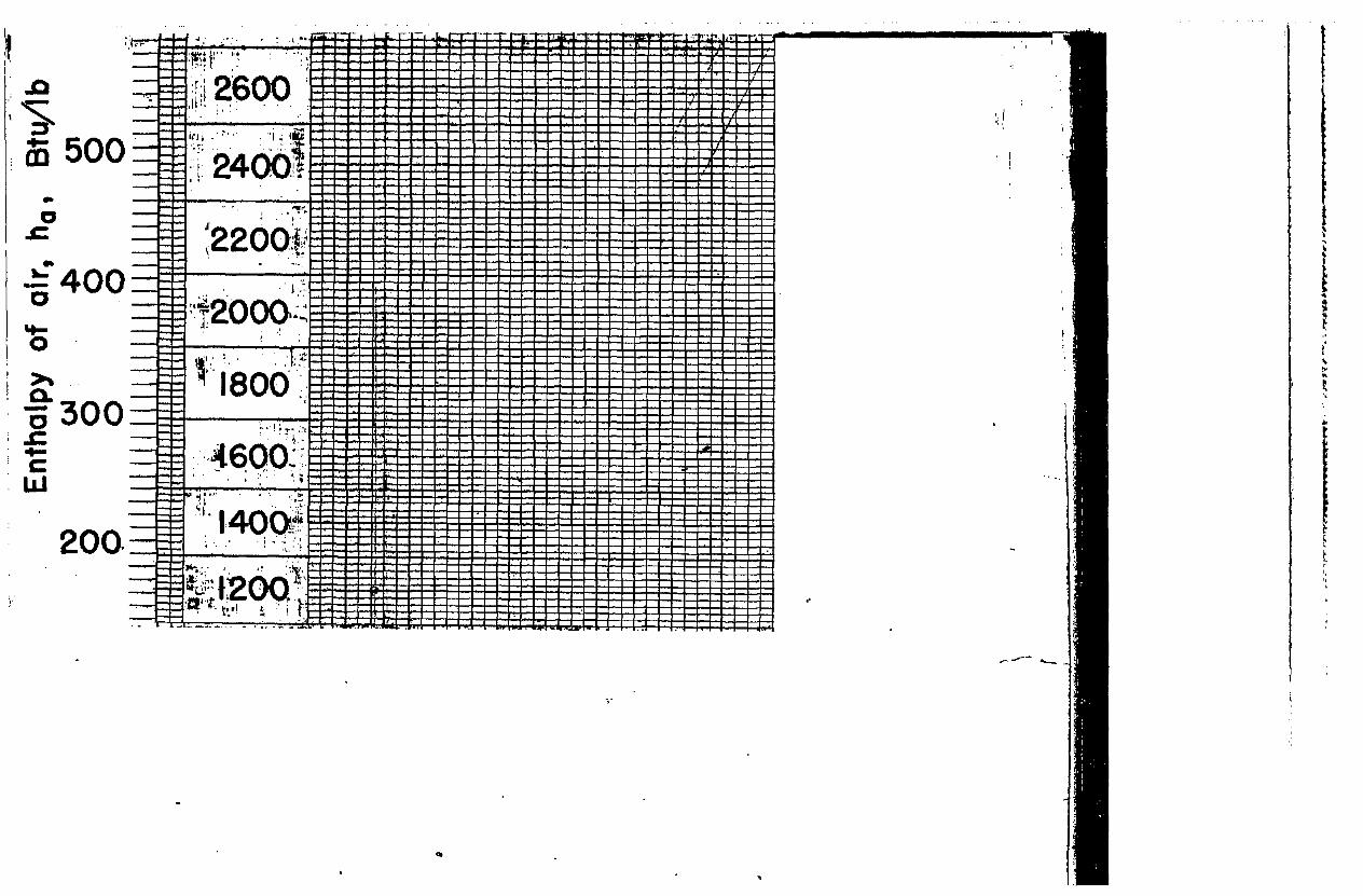
SPECIAL CCXEWSTION CHAKPS
Two special charts for raking combustion calculations have been prepared. (See figs. 5 and 6.) These charts show the temperature rise AT during ideal constant-pressure combustion for a fuel tith a lower enthalpy of combustion hc of -18,700 Btu per pound end a hydrogen-carbon ratio m of 0.175. The plots of the two correction factors ‘B& and Eh that permit the calculation of the fuel-a32 ratio for other fuels with different hydrogen-carbon ratios and lower heating values are included as insert%. The fuel-air ratio f is the product of the chart fuel-air ratio f* and the two factors EG, and E&
The two oorrection factors have been so adjusted that the correction is exact for the average variation of the lower heating value with the hydrogen-carbon ratio of the gasolines, kerosenes, and light fuel 011s currently available. The assumed merage relation is
ho = - (15,935 + 15,800 m) (12)
The correction% are also exact for a hydrogen-carbon ratio of 0.175 for any lower heating value. Small errors exist for other combi&na- tions of heating value and hydrogen-carbon ratio. For example, the fuel quantity calculated for a combustion temperature of 3000° R for a fuel with a hydrogen-carbon ratio of 0.084 will be in error about 1 percent for every 1500 Btu per po~znd that the lower heating value of the fuel varies from the value given by equation (12).
14 . .
. liACA TN No. 1086
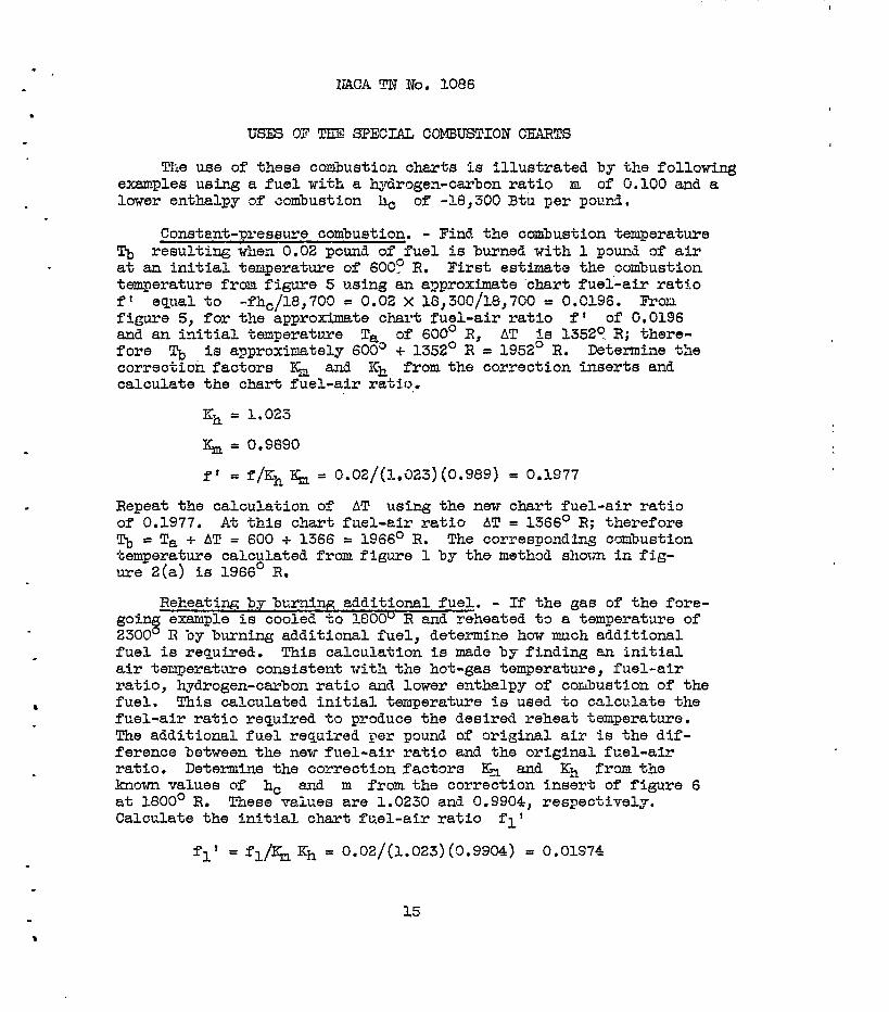
. USES OF TEE SPECIAL COMBUSTION CEARTS
The use of these combustion charts fs illustrated by the following examples using a fuel with a hydrogen-carbon ratio m of 0.100 and a
. lower enthalpy af combustion ho. of -18,300 Btu per pov.nd.
Constant-pressure combustion. - Find the combustion temperature Tb resulting when 0.02 pound of fuel is burned with 1 pound of air at an initial temperature of 6003 R. First estimate the combustion temperature from figure 5 using an approximate ‘chart fuei-air ratio f' equal to -fh,/18,700 = 0.02 X 18,300/18,700 = 0.0196. From figure 5, for the approximate chart fuel-air ratio f* of 0.0196 and an initial temperature Ta of 600' R, AT is 13529 R; there- fore Tb is approximately 600" + 1352' R = 1952O R. Determine the correction factor% I& and Ich from the Correction insert% and calculate the chart fuel-air ratio,
K h = 1.023
I& = O.S890
f' = f&h I(;n = 0.02/(1.323)(0.989) = 0.1977
Repeat the calculation of AT using the new chart fuel-air ratio of 0.1977. At thfs chart fuel-air ratio AT = 1366' R; therefore % = Ta + AT = 600 + 1366 = 1966' R. The corresponding combustion temperature calculated from figure 1 by the method shorm in fig- ure 2(a) is 1966' R,
Reheating, by burning additional fuel. - If the gas of the fore- going example is cooled to lGO0" R and reheated to a temperature of 2300' R by burning additional fuel, d8t0Mnin0 how much additional fuel is required. This calculation is made by finding an initial air temperature consistent with the hot-gas temperature, fuel-air ratio, hydrogen-carbon ratio and lower enthalpy of combustion of the fuel. This c&culated initial temperature 5% used to calculate the fuel-air ratio required to produce the desired reheat temperature. The additional fuel required per pound of original air is the dif- ference between the new fuel-air ratio and the original fuel-air ratio. Determine the correction factor3 I$ and Kh from ths known values of h, at 1800' R.
and m from the correctlon insert of figure 6 These values are 1.0230 and 0.3904, respectively.
Calculate the initial chart fuel-air ratfo fl'
flf = fl& Kh = 0.02/(1.023)(0.9904) = 0.01974
15
.
.
w NACA TN No. 1086
.
. *
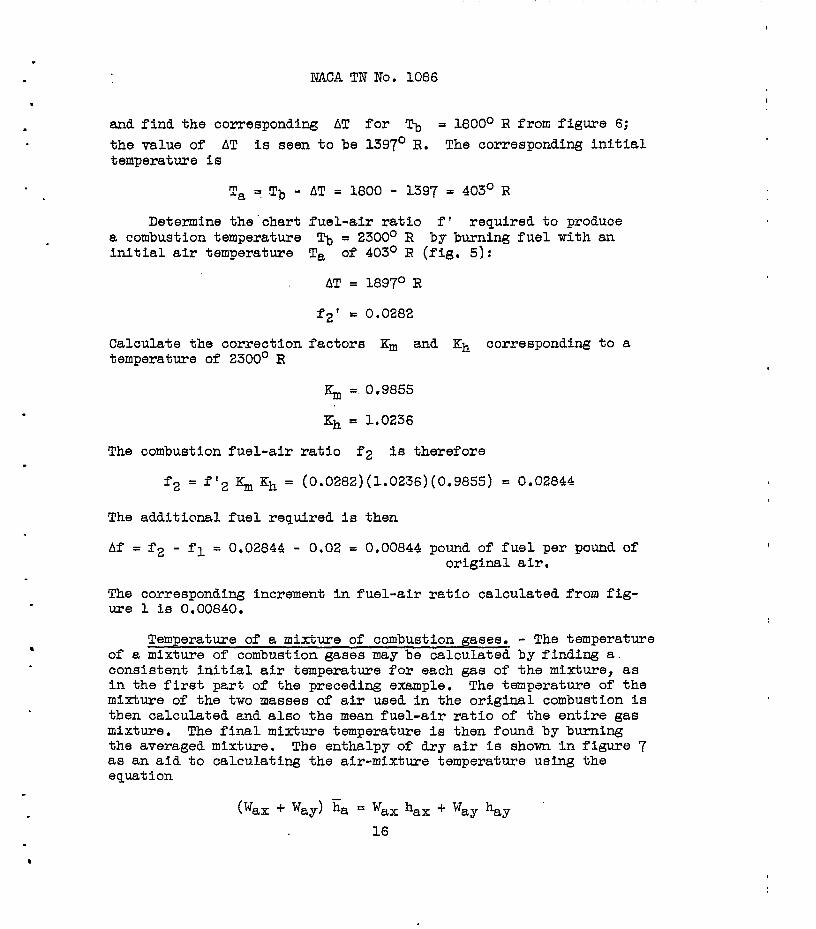
and find the corresponding AT for Tb = 1800° R from figure 6; the value of AT is seen to be 1397' R. The corresponding initial temperature is
Ta E !$, - AT = 1800 - 1397 = 403' R
Determine the‘chart fuel-air ratio f' required to produce a combustion temperature Tb = 23CC" R by burning fuel with an initial air temperature Ta of 403O R (fig. 5):
AT = 1897° R
f2' = 0.0282
Calculate the correction factor% Km and Kh corresponding to a temperature of 2300' R
$, = 0.9855
Kh = 1.0236
The combustion fuel-air ratio f2 is therefore
f2 = f12 "m Kh = (0.0282)(1.0236)(0.9855) = 0.02844
The additional fuel required is then
Af = f2 - fl = 0.02844 - 0.02 = 0.00844 pound of fuel per pound of original air.
The corresponding increment in fuel-air ratio calculated from fig- ure 1 is 0.00840.
Temperature of a mixture of combustion gases, - The temperature of a mixture of combustion gases may be calculated by finding a. conslatent initial air temperature for each gas of the mixture, as in the first part of the preceding example. The temperature of the mixture of the two masses of air used in the original combustion is then calculated and also the mean fuel-air ratio of the entire gas mixture. The final mixture temperature is then found by burning the averaged mixture. The enthalpy of dry air is shown in figure 7 as an aid to calculating the air-mixture temperature using the equation
Cwax + Way) i;s = wax hax + way %3y 16
I NlCA TN No. 1086
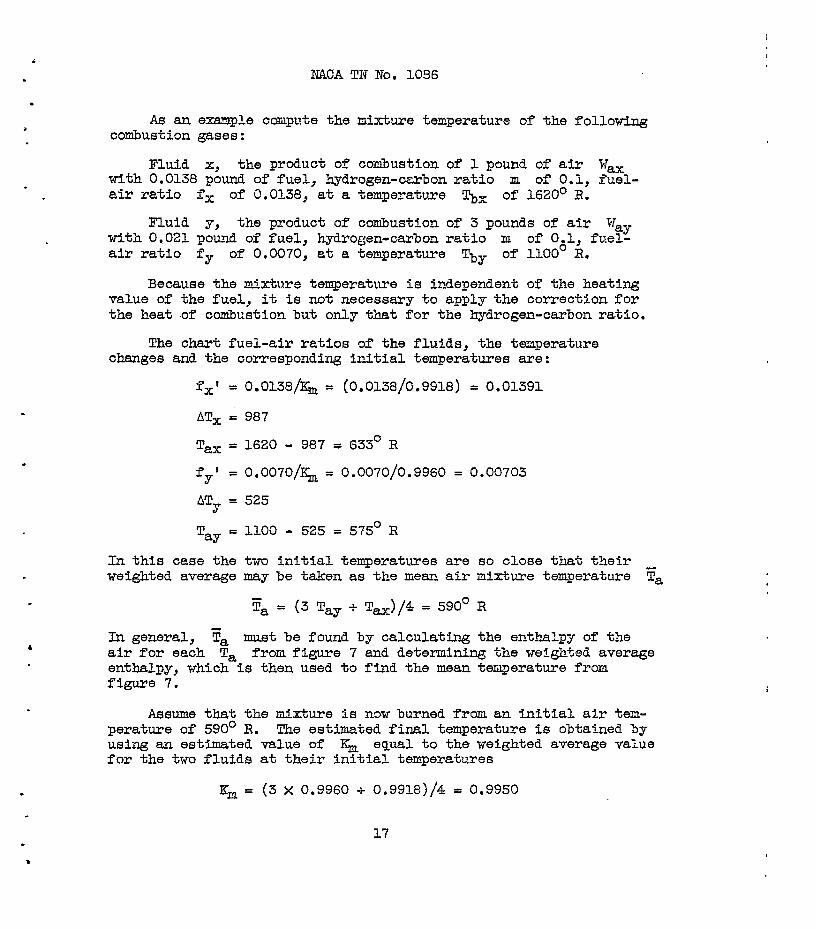
. As an example compute the mixture temperature of the following
cotiustion gases:
. Fluid x, the product of combustion of 1 pound of air Wax
with 0.0138 pound of fuel, hydrogen-carbon ratio m of 0.1, fuel- air ratio f, of 0.0138, at a temperature Tbx of 1620' R.
Fluid y, the product of combustion of 3 pounds of air Way with 0,021 pound of fuel, hydrogen-carbon ratio m of O&l, fuel- air ratio fy of 0.0070, at a temperature Thy of 1100 R.
Because.the mixture temperature is independent of the heating value of the fuel, it is not necessary to apply the correction for the heat of combustion but only that for the hydrogen-carbon ratio.
The chart fuel-air ratios of ths fluids, the temperature changes and the corresponding initial temperatures are:
-I IX’ = 0.0138/I& = (0.0138/0.9918) = 0.01391
AT, = 987
Tax = 1620 - 987 = 633' R
fY' = o.o07o/I(h, = 0.0070/0.9960 = 0.00703
ATY = 525
T w = 1100 - 525 = 575' R
In this case the two initial temperatures are so close that their weighted average may be taken as tbe mew air mixtu.re temperature ya
tFa = (3 Tay + Tax)/4 = 590' R
In general, Fa must be found by calculating the enthalpy of the air for each Ta from figure 7 and determining the weighted average enthalpy, which is then used to find the mean temperature from figure 7.
Assume that the mixture is now burned from an initial air tem- perature of 590° R. The estimated final temperature is obtained by using an estimated value of Km equal to the weighted average value for the two fluids at their initial temperatures
.
I
K& = (3 x 0.9960 + 0.9918)/4 = 0.9950
17

I NACA TN No. 1086
.
. The mean fuel-air ratio of the mixture f ia 0.0087 . f' = 0.0067/0.9950 = 0.008743
From figure 5, therefore 590° + 647o
AT -Le 647O R; the mixtxze temperature lj, is = 1237' R. As a check, the value of E& for
this value of Tb is 0.9951, which is sufficiently close to the assumed value. The corresponding mixture temperature calculated from figure 1 is 1240" R.
This method can be applied to the calculation of the amount of fuel necessary for reheating by burning additional fuel and to the calculation of mixture temperatures only If the apparent inittal temperatures corresponding to the given state of the burned mixtures are real physical temperatures. The calculations can be made from figure 1 without regard to this limitation,
Aircraft &@ne Research Laboratory, Rational Advisory Committee for Aeronautics,
Cleveland, Ohio, October 10, 1945.
18

I
NACA TN No. 1086 .
. APRENDIXA
CORRF,CI'ION OF HEATS OF COMBUSTION TO THE RELE'EEGNC!R
TEMPERATURE OF 540° R
The heati& value usually determined from measurementa in a combustion bomb is the lower internal energy of combuetion at constant volume ec rather than the lower enthal?y of combustion. For most uses, the differences between these two heats of combus- tion are negligible.
The difference (-ec) - (-ho) is due to the work done dis- placing the atmosphere TAV which ie equal to A(PV) for the processes at constant pressure. The gaB constant of the burned mixture ie given by equation (21) of reference 1,
(1 c f) Rb = Ra+fAA 4.032 m + 1
and the external work done in (in Btu/lb of fuel) therefore
a constant-temperature process: iS
m -T 4.032 J m + 1 m+l
For example,,the difference (-ec) - (-h,) is 40 Btu per pound for octane at 5400 R, The midmum probable error in very precise measurements is about 25 Btu ?er pound. In most ordinary deter- minatione, the probable error is between 50 and 100 Btu per pound and therefore is larger than the difference between -of.? and -h,.
The heat of combustion Is etated for a reference temperature Tr, usually 15O C to 25' C (59O F to 77’ F). The variation of the heat of combustion in this range is, however, very much smaller than the uncertainty in the measurements. For hydrocarbon fuels, the lower heating value Increases with temperature according to the relation,
d( -h,) = Cpf - am+b 2,242 m + 0.1573
dT m+l = Cpf - - m+l
19
NACA TN No. 1086 I
.
.
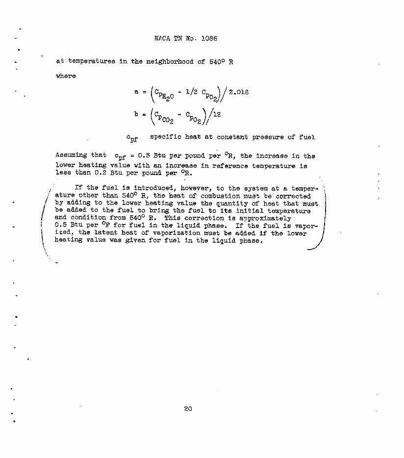
. at temperatures in the neighborhood of 540° R
where
b-
=Pf specific heat at constant pressure of fuel
Assuming that cPf = 0.5 Btu per pound per %, the increase in the lower heating value with an increase 1n reference temperature is less than 0.2 Btu per pound per OR.
If the fuel is introduced, however, to the system at a temper- !: ir ature other than 540° R, the heat of combustion must
f be corrected i
!
by adding to the lower heating value the quantity of heat that must be added to the fuel to bring the fuel to its initial temperature and condition from 540° R.
i Thie correction is approximately
\
0.5 Btu per OF for fuel in the liquid phase. If the fuel is vapor- ized, the latent heat of vaporization must be added if the lower
\ heating value was given for fuel in the liquid phase,
'.
.
.
20

i
I _- 1 -. -.!
443 - _ --_-. -.
4’ -I--
,Pc+” - -.-..-..-- -
43 - I - - - - - - I
jil_ -- r , J-r --I_-.- ___-.- ---- . . . .
c e/ -.--.- - -
4-Y .-. . , _ .- .._-- l S”
- _ I----
, 713’
t-
----_-
..-- --.- ._., .-- -.._ I_- _^. -
_/(B 2-d - -. -.- . . . 1 --z z---.-. ._ -- -
a --------- - - - I -
- . . - - _ -_
.a - ----..--_-- I_- - - - - .-.-..__-
_ __--. - - . -
I - - - - - . - - I
.-. _. - --..-- .- -
‘! .-_ .-. -- - . -. -- - -* .-..- ---__._- - I - . . .----__.
- .,- _- 1 .-. -. .I --.-1 - -. -.--- -
_.- .-- - - .-
e
_._,.-.-_ _----_ -. - I - . ._ . . - - . - .-_ .-._ - - - -
.-. _. - _ _. ._ ” ..---- ; .- -.---.-
d :;
_.- ._. -.-I -- .-..- - -L -..-. -.--.--
-.---1- - . - - - - - --.- .” -. -..-- - --” - .- -...-_ - .._ .--- -.. I ~ _,. ; .-.. ~
.--... -.---. ----
.- ._-. -- ---- -_--_-.---.- - - - - -_r. ---- . . ..I..~ -
_ -_._. -.-.. --.--_.------..---._- -..- ---- --.- -_--
w
_.-_-. -. -_-_^ --- - - - .-.--.- - ._.-. ~--_ -.-- .--.-.. -----I- ---.----.
__. _ _ _ - _-. I_ .- .-_.- - -- -..--.,. .--_ 1--------.-------- .---- - - .- .- . - .- _ - - -. _ _ 1
I
,
.
NACA TN No. 1086
APPENDIXB
.
THl3 AFTERBURNING OF RI--THAN-STOICHIOmIC EXHAUST GASES
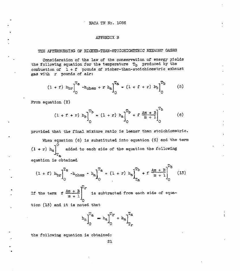
Consideration of the law of the conservation of energy yields the following equation for the temperature Tb produced by the combustion of 1 + f pounds of richer-than-sooiohiometrlc exhaust gas with r pounds of air:
(1 + f) Te
hbr I 'hchem + r ha 0 I
Ta = (1 + f + r)
Tb hb
I (5)
0 0
From equation (2)
Tb Tb Tb
(1 + f f r) hb 1
= (1 + r) ha 1 +fAm+B m+l (6) 0 0 0
provided that the final mixture ratio is leaner than stoichiometric.
When equation (6) is sUbstitut8d into equation (5) and'the term
1 0 (1 + r) ha added Ta
equation is obtained
to each side of the equation the following
.
m Ae Ta = (1 % Tb
(1 + f I hbr 1 ‘hchem - ha 1 +r)ha Am+9 +f m+l (13) 0 0 L
1 Ta I 0
Tr If the term f t 1 t 1 is subtraCt8d from each stale of equa-
0 tion (13) and it is noted that
the following equation is obtained: 21

.
A NACA TN No; 1086
.
.
.
.
Th8 Va1u8 Of the first four t9Z'l.W Of th8 left-hand Side of 8QU3- tion (14) depends on the teznperature and the coqositiox of the hot exbmst gas. The calculation of the mm of these t8rmS cm1 be simplified by a suitable collection of terms. For convenience let
I Te Q = (1 f f> hbr -&a - (8) 0
The ~alU8 Of th8 first tW0 t8EUI.s (1 + f> hbrlTe 'h&em may be cal- m! 0
culated from equations (25) and (26) and table II of refarence 1:
(*2)a (HZ) (1 + f) hb, -hchem = h, - r C + f ; 1 YE + y 3 (15)
where
C = Ho 2 + %o - 73202
D= ( 2HcO - Hco, /
)I IL2
E= i HH20 + HcO 1 HCO
Y 2.016
2/ F = =co2 + H% - =CO - =H,O
The ent?&alpy as defined by equation (26) in reference 1 includes the chenical enthalpy. When equatiom (3) and (15) are combined,
- .
3 n = ha
22

. l
.
.
.
NACA TN No. 1086
Equation (16)may be simplified by writing
where
I Te
U=ha - Tr
x = El4 *- *I;
W = F/SIT' 0
07)
The values of U, X, Y, and W, which are functions only of Te, are givsn in table II for dry air. The values of (HZ) computed by means of equation (25) of referer,ce 1 are given in tab18 III.
1, Pinkel, Benjamin, and Turner, L. Richard: Thermodynamic Data for the Computation of the Perfcrmance of Exhaust GM Turbines. NACA ARR No, 4B25, 1944.
2. .Davis, Clyde O., and Johnston, Herrick L.: Heat Capacity &es of the Simpler Gases, V. The Haat Capacity of Hydrogen at High Temperatures. The Entropy and Total Energy. A Corrected . Table of the Free Energy abcve '2000°. Jcur. Am, Chem. SOC., vol. 56, no. 5, May lS34, pp. 1045-1047.

. NACA TN ND. 1086
. .
3. Johnston, Herrick L., and Davis, Clyde 0.: Heat Capacity Was Of the SiIIIpl3r kS3S. N. Extension of the "Free Energy" Formula of GiaUqU8 and Overstraet to Yield Reliable Approx- mation Formulas for the Calculation of Entropy and of Heat Capacity from Spectroscopic Data. &tropy and Heat Capacity of Carbon Monoxide and of Nitrogen from Near Zero Absolute to 5OOoo R. Jour. Am. Chem. Sot., vol. 56, no. 2, Feb. 1934, pp. 271-276.
4. Johnston, Herrick L., and Walker, Margery K.: Heat Capacity Curves of the Simpler Cases. II. Heat Capacity, Entropy and Free Energy of Gaseous Oxygen from Near Zero Absolute to 5ooo" II. Jour. Am. Chem. Sot., vol. 55, no. 1, Jan. 1933, pp. 172-186.
5. Johnston, Herrick L., and Walker, Margary K.: Heat Capacity Curves of the Simpler Gases. VII. The High Temperature Heat Capacities of Oxygen and Influence of 16 Level on the Thermo- dynamic Properties of the C&s. Jour. Am. Chsm. SOC., vol. 57, no. 4, April 1935, pp. 682-684.
6. Cordon, A. R.: The Calculation of Thermodynamic Quantities from Spectroscopic Data for Polyatomic Molecules; the Fr83 Energy, Entropy and Heat Capacity of Steam. Jour. Chem. Phys., vol. 2, no. 2, Feb. 1934, pp. 65-72; vol. 2, no. 8, Aug. 1934, p. 549.
7. Stephenson, C. C., and McMahon, H. 0.: The Rotational Partition Function of the Water Molecule. Jour. Chem. Phys., vol. 7, no. 8, Aug. 1939, pp, 614-615.
8. Kassel, Louis S.: Thermodynamic Functions of Nitrous Oxide and Carbon Dioxide. Jour. Am. Chem. Sot., vol. 56, no. 9, Sept. 1934, pp. 1838-1842.
24

.
NACA TZr ND. 1086
TABLE I - FACTORS FOR COMPUTING THE ENTiXALPY
OF W-MIXTURE COMBUSTION GASES
200 360 85.99 300 540 129.13 I
----m---- -------w 1,195.8 26.04;
400 720 172.48 1,602.g 60.76'i 500 900 216.40 2,016,9 105.33 600 1080 261.13 2,442.e 157.18 700 1260 306.85 2,884.g 214.38 800 1440 353.62 3,343.3 276.07 900 1620 401.38 3,821.0 341.50
1000 1800 450.04 4,321.6 410.00 1100 1980 499.54 4,842.g 481.42 1200 2160 549.73 5,388.6 554.75 1300 2340 600.58 5,956.e 630.25 1400 2520 651.90 63548.9 707.92 1500 2700 703.86 7,152.6 785.50 1600 2880 756.19 7,780.B 865.00 1700 3060 808.94 8,423.l 945.33 1800 3240 862.04 9,081.3 1026.58 1900 3420 915.47 9,754.2 1108,25 2000 3600 969.17 10,440.2 1190.25
1 @tub) A B
National Advisory Committee for Aeronautics
25

.
I
.
. .
.
XACA TN NJ. 1066
TABIX II - FACTORSFOR CCWUTINGTHEENTHALPY
OF RICH-MIXTURE EXHAUST GAS
300 400 500
;: 800 900
1000 1100 1200 1300 1400 1500
j T i (OR)
U
540 720 900
1080 1260 1440 1620 1800 1980 2160 2340 2520 2700
l-1756.90 ' -1716.47 -1673.67 -1628.85 -1582.24 -1534.01 -1484.37 -1433.51 -1381,52 -1328.68 -1275.49 -1220.61 -1165.61
x I y t wl
60,115.4 20,198.8 -610.76 60,622.O 26,267J -602.85 61,074.g 20,324.6 -590.97 61,497.5 2Oj375.4 -576.84 61,909.3 20,422.4 -561.91 62,318.2 20,467 -546.44 62,731.2 20,511 -531.03 63,156.2 20,554 ' -516.02 63,592 20,597 -501.21 64,048 20,640 -487.51 64,517 20,683 -473.56 65,006 20,725 -460.51 65,505 20,768 -447.61
TABLE III - HYDROGEN CONTENT OFEXMJST GAS
Fuel- Hydrogen-carbon ratio of fuel air I ratio 0.084 0.100 0.125 0.150 0.175 0.189 0.200
r + Concentration of hybogen, mole per mole or original air
0.07 ------- ---M--m ----I-- O.OClOO 0.00398 0.00597 0.00764 .08 0.00323 0.00543 0.00984 .01530 .02190 ,02560 .02881 .09 .01218 .01662 .02478 .03408 .04431 ,05035 .05518 .lO .02380 .03091 .04332 .05677 .0'/094 .07909 .08551 .ll .03803 .04809 .06499 .08260 .10061 .11077 .ll870
, .12 .05471 .06779 .08918 .11083 .13250 .14456 .15391 National Advieory Committee
for Aeronautics
26

NACA TN No. 1086 .
i .
Fig. I
Ratlo of welphrr of orfslml air. I
NATIONAL AOVISORY COkMlTTEE FOR AERONAUTICS
Figure I. - Constant-pressure alinement chart. (A 250 by 259 in. print of this figure is attached.)

Fig. 2a NACA TN No. 1086
Roti of wiphtc 00 origsral air, c
800 .OYS
800 .Q10
700 .08S
800 .oao
0
5 ?i 100 .OZI -
‘0 a’ P 5 i 2 c 400 .020 &
3 f2 z 2
2 t c j a00 .016 -
200 .OlQ
IO0 .ooc
‘I
0 0
-20r000 -18,000 -12,000 -8,000 4,000 0 -20,000 -18,000 -12,000 -8,000
Lowrr enthalpy of combustion, h,, Btu/lb NATIONAl AOVISORY
(a) Constant-pressure combustion. COMMITTEE FOR AER0NAUtlCI.
figure 2. - Use of the constant-pressure alinement chart.
.
. ’
.

NACA TN No. 1086 Fig. 2b
.
.
Ratio of rofgktc of origlnsl air, r ,
.
.
Fi
.oao
.oar
.oao
c
L
.020 7
7s
LOISi
0
-20,000 -18.000 -12,000 -8,000 -a.000 0 -20,000 -18.000 -12,000 -8,000
Lowar onthalpy at combustion, h,, Mu/lb N~~,~~ AOVISORr
CMMITTEE FOR AERONAUTICS
fb) Reheating by burning additional fuel. gure 2, - Continued.
c
.

Fig. 2c
.
NACA TN No. 1086
Ratio of wrlghtc of ori#lnol air, r
.oto
-20,000 -IE,OOO -IP,OOO -8,000 -Y,OOO 0 -20,000 -18,000 -l2,000 -8,000
Loror enthrley of oombrrtlon, ho, 22dlb NATIWAL K)VISORY
COWITTLE CON AERONAUTICS
(c) Change in enthetpy of a burned mixture with a change in temperature.
Figure 2. - Continued.
.
. .
I
.
.
NACA TN No. 1086
Ratio of weights of OrigiNal sic, r
Fig. 2d
-20.000 -16,000 -12,000 -8,000 -6,OOC 0 -20.000 -lb,000 -12,000 -6,000
Lower enthclpy of combustion. h,. Eta/lb NkTlONAL ADVISORY
COMYI Tllx FOR AERONCUT I lx
(d) Temperature of a mixture of combustion gases. Figure 2. - Concluded.
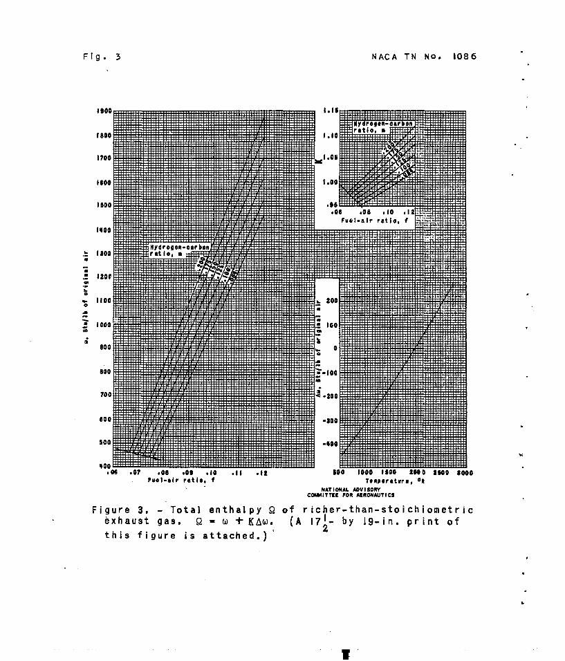
Fig. 3 NACA TN No. 108 6
ItOQ
1100
1000
800
Ii0
700
800
500
400 l w 107 *IO .II .I2 coo 1000 1200 2000 2200 a000
f
Fuel-rlr ratio, f _ -
T~mporrturo, on
NATIONAL AOVISORV CINUAITTCE FOR AERONAUTICS
Figure 3. - Total enthalpy Q of richer-than-stoichiometric Exhaust gas. $2 - o +KAo.
this figure is attached.)' (A 17:- by 19-in. print of
,
.
., .

NACA TN NO. I086 Fig. 4
= 600 2 L y”
200
Ratio of weight8 of original air, r
.016
.0&O
.oas
.C
.oao
.OPS * .
2 *I
,020 : L
‘f
IIC u’
.OlO
.006
0
800
606
.
Lower onthalpy of oomburtlon, h,, Btu/lb NATIONAL ADVISORY
COMMI TEE FOR AERONAUT1 CS
Figure 4. - Us8 of the constant pressure alinement chart to determine the temperature of after burning of richer-than- stoichioaetric exhaust gas,
.

Fig. 5 NACA TN No. 1086 ,
Figure 5. - Temperature rise during ideal constant-pressure combustion as a function of initial temperature; f.. f'KmKh. (A 15- by 21-in. print of this figure is; attached.)
.
.
. .

2300
2400
2200
= 2000 .
. r w .
: 1300 L
,
. t
1200
1000
300
600
IN N’J- Fig. 6
0 0 .Ol .02 .03 006 .06
. Chart furl-air ratio, f'
Figure 6. - Temperature rise during ideal constant pressure combustion as a function of the combustion temperature; f = f'KmKha (A 16- by 21-in. print of this figure is
attached.1

290
220
200
‘c
Q 100 2
;; 2 60
.: 00
10
20
0
-20
-40
-60 300 BOO LOO LOO 700 000 900 1000 II00 I200 I300 IbOO
Tewerature, T,, OR NAT IONAL ADV I
Ire 7. - Enthrlpy of air. COMMITTEE FOR AEA SORY
101 NJT I CS

I
NACA TN NO. 1086
I900
I 800
I700
I600
1500
1400. .--.-.-
1300
1200

T .-
1
’ NACA TN NO, 1086
I900
I 800
I700
1600
I500
1400. ,-- -.
I300
1200
I i’ ,;I
.
Figi ;{3 ,’
; .\ I .:
./

900
800
700
600
500
4oo( . 16 .07 08 .09 .I0 .I I .I2 Fuel-air ratio, f .
\ Figure 3.- Total enthalpy a of richer-than-stoichiometric exhaust gas. a -0 +Kh
560 1600 I%0 2000 2500 3000 Temperature, OR
200
100
0
400
200
300
400

. . ,..
,:
.- *;
,.-.._ :- _.’ .
-
3400
3200
3000
2800
2600.
-2400.
2200
-2000
I800
1.02
1.00 E

I6Od
1400
I200
IO00
800
600
400
200,
n
Chart fuel -air ratio, f1 Figure 6.- Temperature rise during ideal constant-pressure combustion as a funct
of the combustion temPeratlw: f=.flKmKh#
. :. .: :.e -:-:
,; .,, , . - ._ : ., . : .-,;. .

.’ . ;, ._ _I :. .,. . ..,, i : : ,, /. :., ,, _. . . -. .:. ; . : . . . . . ,-,.~,y.. . ‘..I .,I’ . . : ; -_7 , ._ _’ .. ._ . . ‘G.’
..:.. ,../ :” .:
--,-‘. . IL - . . . . . : .; 9;; .’
,.<, ..‘: .,*_..’ .._ .- -i ._I’ L.“. . . c
1600
,800
600
.02 .03
Chart fuel-air ratio, f’
Figure 5. - Temperature rise during ideal constant-pressure combusfibn nc n
’ 1 i!NACA! TN N0.j 1086
3200
.2800
2600
2,400
I
Fig. 6
_:- ” ‘r - P..
_’ _. . .
.’
: . : . . . ,:;. ;_, : .I __ :. ; . .. :.
:.
;; :
‘,J ..:,.:. ,‘..._ .. ‘__ ., :.; ..,i
I’. _,., I~‘..” ., . . . .
. . . . . . :
: ‘..

Fig. I
--.
._
,
_--- 4,
,
1 1 t t
,
.

ix)
i
I ,
’ tion
I” i;Jrt-.. I ( I
I
>: ’ ,I.’ :
. . . .
.
h

si’ ‘.,
1 .’ ;,:
0
4
,
I
,* .
weight6
800
c 2 b.7 0
500
400
300
200
.

r ATI- 7934
TITLE: Thermodynamtc Charts for the Computation of Combustion and Mixture Temoeratures at Constant Pressure fN'onfO
AUTHORJS) : Turner, L. R.; Lord, A. M. ORIG. AGENCY : Aircraft Engine Research Laboratory, Cleveland, 0. PUBLISHED BY : National Advisory Committee for Aeronautics, Washington, D. C.
OOtO. AOBtCY HO
TN-1086 nnuucKO BO.
(Same) 6*11 I H.l. OAn
Jmr ' *i 1 Unclasa. COUMTDT
U.S. English HlUtTtATKMd
tables, eraohs ABSTRACT:
Charts are presented (or calculating combustion temperatures and temperature changes Involved in constant-ores sure thermodynamlc processes of air and hydrocarbons. Charts are applicable only to processes In Thick final fuel-air ratio is leaner than stolchiometric and at temperatures There dissociation is unimportant. They may be aoolled to steady-state flow processes. Examples of aooUcatlon are given.
DISTRIBUTION: SPECIAL. All requests for copies must be addressed to: Publishing Agency. DIVISION: SECTION: ,£eofcas»T>irf£^
ATI SHEET NO.: Control Air Oecumonra Offteo
| Wrtehl-Panorcca Al# Porto Ones, Dayton, Ohio
SUBJECT HEADINGS: Combustion-Temperature-Calculation (23657) Fuel-Air mixtures - Combustion (42262.25)
Aia recti Oi