1118 grk-4 en - gems naven.gemsnav.com/upload/file/20160816/1118_grk-4_en.pdf · installation and...
TRANSCRIPT
Doc.No.1118 Rev.015 2016-08-16
Tel: +86-755-29644311 Fax: +86-755-29644383-816 Email: [email protected] GEMS NAVIGATION LIMITED Room301,HuaChuangDaBuilding,CuizhuRd,46District,Bao’an,Shenzhen,China.
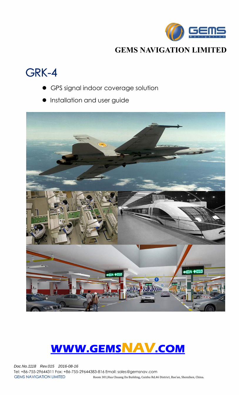
GRK-4 GPS signal indoor coverage solution
Installation and user guide
WWW.GEMSNAV.COM
GEMS NAVIGATION LIMITED
Doc.No.1118 Rev.015 2016-08-16
Tel: +86-755-29644311 Fax: +86-755-29644383-816 Email: [email protected] Web: www.gemsnav.com Page 2 / 14
GRK-4 System signal: GPS L1(1575MHz);
This is four point solution, covers 5-20 meters at radius (by increasing the amplifier according to methods and under field conditions, building height and other certain conditions reach a radius of 20 meters).
Note: Four point means many antenna be used to transmit GPS signal.

Doc.No.1118 Rev.015 2016-08-16
Tel: +86-755-29644311 Fax: +86-755-29644383-816 Email: [email protected] Web: www.gemsnav.com Page 3 / 14
System Schematic
l 1. GPS Antenna(TIMING 4000) be installed on roof of the building;
2. Cable assembly RG8 fixed along the out wall, one terminator connects TIMING4000,the another to protector at the appropriate place. In some special environment, select PE or PVC material plastic pipe to protect the cable assembly is quite sensible;
3. Protector and Step Adjustable Amplifier are fixed on ceiling or on the table;
4. Cable assembly KSR240 is fixed along the ceiling of the operating place;
5. Antenna GRA10 be fixed on the ceiling .
According to the actual environment, you can adjust positions of some parts, which can make you the adjust, change and overhaul more easily.
GPS L1
GPS Antenna(TIMING4000)
Antenna (GRA10),4
Step Adjustable Amplifier (RGA30-SV4)
KSR240, 20M,4
Protector
INDOOR
GPS device
GPS L1 signal RG8, 30M

Doc.No.1118 Rev.015 2016-08-16
Tel: +86-755-29644311 Fax: +86-755-29644383-816 Email: [email protected] Web: www.gemsnav.com Page 4 / 14
Quality Commitment
All products have been strictly inspected, all are qualified products.
We promise one‐year guaranty and 5‐year available.
Under warranty, products gone wrong which be identified not be human factor, can be replaced free or repaired. Freight be charged by GEMS.
Return Policy
Our product and its packaging have LOGO and Serial‐number, you should not tear up them, as we will depend on them to deal with the return product.
We haven’t recruit agencies, sales and after service be took charged by GEMS. Please pay attention.
Service phone:86-755-29644311or email to:[email protected], We will response in 24 hours.
Doc.No.1118 Rev.015 2016-08-16
Tel: +86-755-29644311 Fax: +86-755-29644383-816 Email: [email protected] Web: www.gemsnav.com Page 5 / 14
Contents
1 Functional Description ............................................................................................................................................................... 6
2 Typical Application .................................................................................................................................................................... 6
3 Standard Configurations: ........................................................................................................................................................... 6
4.Topological (Under standard configuration) .......................................................................................................................... 7
5. Kits include ............................................................................................................................................................................... 8
5.1 Step Adjustable Amplifier RGA30-SV4 ......................................................................................................................... 8
5.1.1 Function: .............................................................................................................................................................. 8
5.1.2 Specification ........................................................................................................................................................ 9
5. 2 Antenna ........................................................................................................................................................................ 10
5.2.1 GPS antenna(Receiving antenna): TIMING 4000 ..................................................................................... 10
5.2.2 Transmiting antenna:GRA10 .......................................................................................................................... 11
5.3 Cable Assembly ......................................................................................................................................................... 12
5.3.3 Select Connector ................................................................................................................................................ 12
5.3.1 RG8(KSR 400) .................................................................................................................................................. 12
5.3.2 KSR 240 ............................................................................................................................................................. 12
5.4 Model Naming Rules ................................................................................................................................................. 13
5.5 Frequency Reference Table ........................................................................................................................................ 13
6.Typical faults and solutions ..................................................................................................................................................... 14
Doc.No.1118 Rev.015 2016-08-16
Tel: +86-755-29644311 Fax: +86-755-29644383-816 Email: [email protected] Web: www.gemsnav.com Page 6 / 14
1 Functional Description
GRK‐4 is a repeater operates by receiving GPS satellite signals with an antenna located outside the
building and re‐radiating the signals into the indoor area or covered space where satellite signal cannot
reach.
GRK‐4 is a four point GPS repeater, four transmitting antenna transmit GPS L1 signal. This solution offer
adjustable test signal to receiver.
If need extend the system, you can add assemblies and sending antennas, so as to cover satellite signal
indoor large area and more rooms or buildings.
Other documents, log in website::www.gemsnav.com ,or contact:[email protected],或
or call the technical service: 86-755-29644311。
2 Typical Application
For GPS products testing For testing the cell‐ phone with GPS, PND, car navigators, tracker, survey products, etc.
For the purpose of GPS signal covering Car parks, lab, aviation manufacturing hangar, trade shows, Emergency‐, safety vehicles, public
transportation etc.
3 Standard Configurations:
StepAdjustableAmplifier:RGA30‐SV4,1ea; ReceivingAntenna:TIMING4000,1ea; CableAssembly:RG8,30M,1ea; CableAssembly:KSR240,20M,4ea; SendingAntenna:GRA10,4ea. Ligting‐protector:1ea;

Doc.No.1118 Rev.015 2016-08-16
Tel: +86-755-29644311 Fax: +86-755-29644383-816 Email: [email protected] Web: www.gemsnav.com Page 7 / 14
4.Topological (Under standard configuration)
Signal
Radius:5M-20M
GPSAntenna:TIMING4000(receiving)
Lighting‐protector
Step Adjustable Amplifier:RGA30‐SV4
Antenna:GRA10(transmit),4
RG8,30M
KSR240,20M,4
Top-level outdoor
Workshop(Indoor)
Doc.No.1118 Rev.015 2016-08-16
Tel: +86-755-29644311 Fax: +86-755-29644383-816 Email: [email protected] Web: www.gemsnav.com Page 8 / 14
5. Kits include
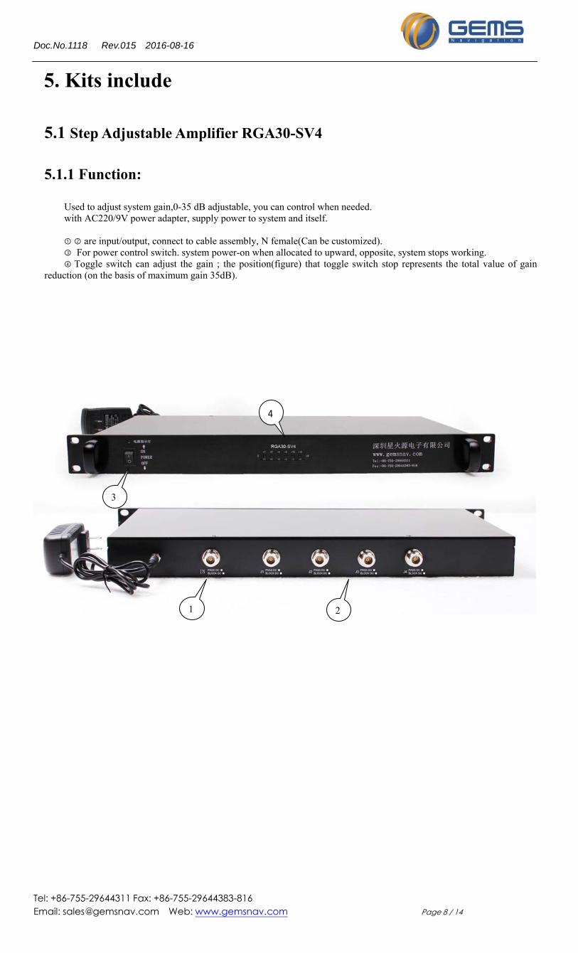
5.1 Step Adjustable Amplifier RGA30-SV4
5.1.1 Function:
Used to adjust system gain,0-35 dB adjustable, you can control when needed. with AC220/9V power adapter, supply power to system and itself. ① ② are input/output, connect to cable assembly, N female(Can be customized).
③ For power control switch. system power-on when allocated to upward, opposite, system stops working. ④ Toggle switch can adjust the gain ; the position(figure) that toggle switch stop represents the total value of gain
reduction (on the basis of maximum gain 35dB).
4
3
1 2
Doc.No.1118 Rev.015 2016-08-16
Tel: +86-755-29644311 Fax: +86-755-29644383-816 Email: [email protected] Web: www.gemsnav.com Page 9 / 14
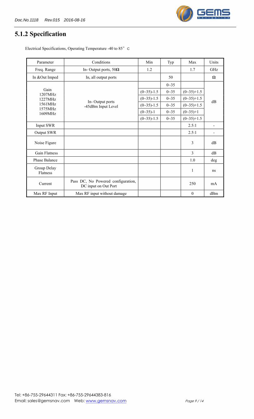
5.1.2 Specification
Electrical Specifications, Operating Temperature -40 to 85°c
Parameter Conditions Min Typ Max Units
Freq. Range In- Output ports, 50Ω 1.2 1.7 GHz
In &Out Imped In, all output ports 50 Ω
Gain 1207MHz 1227MHz 1561MHz 1575MHz 1609MHz
In- Output ports
-45dBm Input Level
0~35
dB
(0~35)-1.5 0~35 (0~35)+1.5
(0~35)-1.5 0~35 (0~35)+1.5
(0~35)-1.5 0~35 (0~35)+1.5
(0~35)-1 0~35 (0~35)+1
(0~35)-1.5 0~35 (0~35)+1.5
Input SWR 2.5:1 -
Output SWR 2.5:1 -
Noise Figure 3 dB
Gain Flatness 3 dB
Phase Balance 1.0 deg
Group Delay Flatness
1 ns
Current Pass DC, No Powered configuration,
DC input on Out Port 250 mA
Max RF Input Max RF input without damage 0 dBm
Doc.No.1118 Rev.015 2016-08-16
Tel: +86-755-29644311 Fax: +86-755-29644383-816 Email: [email protected] Web: www.gemsnav.com Page 10 / 14
5. 2 Antenna
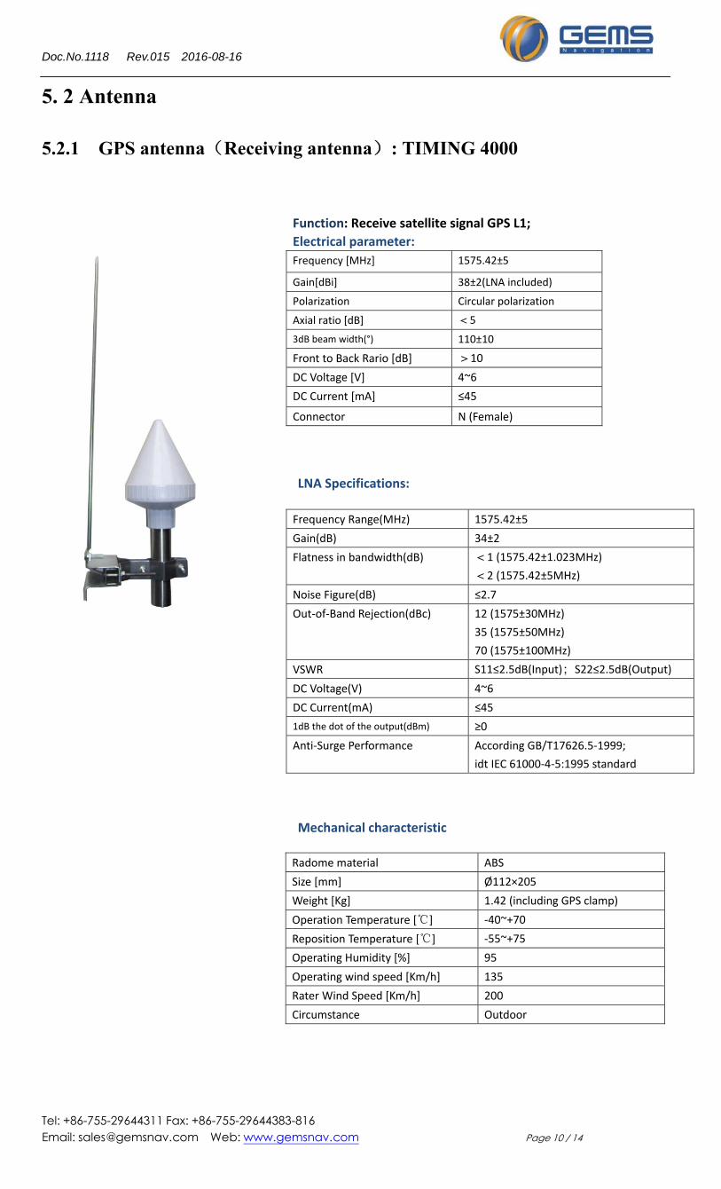
5.2.1 GPS antenna(Receiving antenna): TIMING 4000
Function: Receive satellite signal GPS L1;
Electrical parameter:
Frequency [MHz] 1575.42±5
Gain[dBi] 38±2(LNA included)
Polarization Circular polarization
Axial ratio [dB] <5
3dB beam width(°) 110±10
Front to Back Rario [dB] >10
DC Voltage [V] 4~6
DC Current [mA] ≤45
Connector N (Female)
LNA Specifications:
Frequency Range(MHz) 1575.42±5
Gain(dB) 34±2
Flatness in bandwidth(dB) <1 (1575.42±1.023MHz)
<2 (1575.42±5MHz)
Noise Figure(dB) ≤2.7
Out‐of‐Band Rejection(dBc) 12 (1575±30MHz)
35 (1575±50MHz)
70 (1575±100MHz)
VSWR S11≤2.5dB(Input);S22≤2.5dB(Output)
DC Voltage(V) 4~6
DC Current(mA) ≤45
1dB the dot of the output(dBm) ≥0
Anti‐Surge Performance According GB/T17626.5‐1999;
idt IEC 61000‐4‐5:1995 standard
Mechanical characteristic
Radome material ABS
Size [mm] Ø112×205
Weight [Kg] 1.42 (including GPS clamp)
Operation Temperature [℃] ‐40~+70
Reposition Temperature [℃] ‐55~+75
Operating Humidity [%] 95
Operating wind speed [Km/h] 135
Rater Wind Speed [Km/h] 200
Circumstance Outdoor
Doc.No.1118 Rev.015 2016-08-16
Tel: +86-755-29644311 Fax: +86-755-29644383-816 Email: [email protected] Web: www.gemsnav.com Page 11 / 14
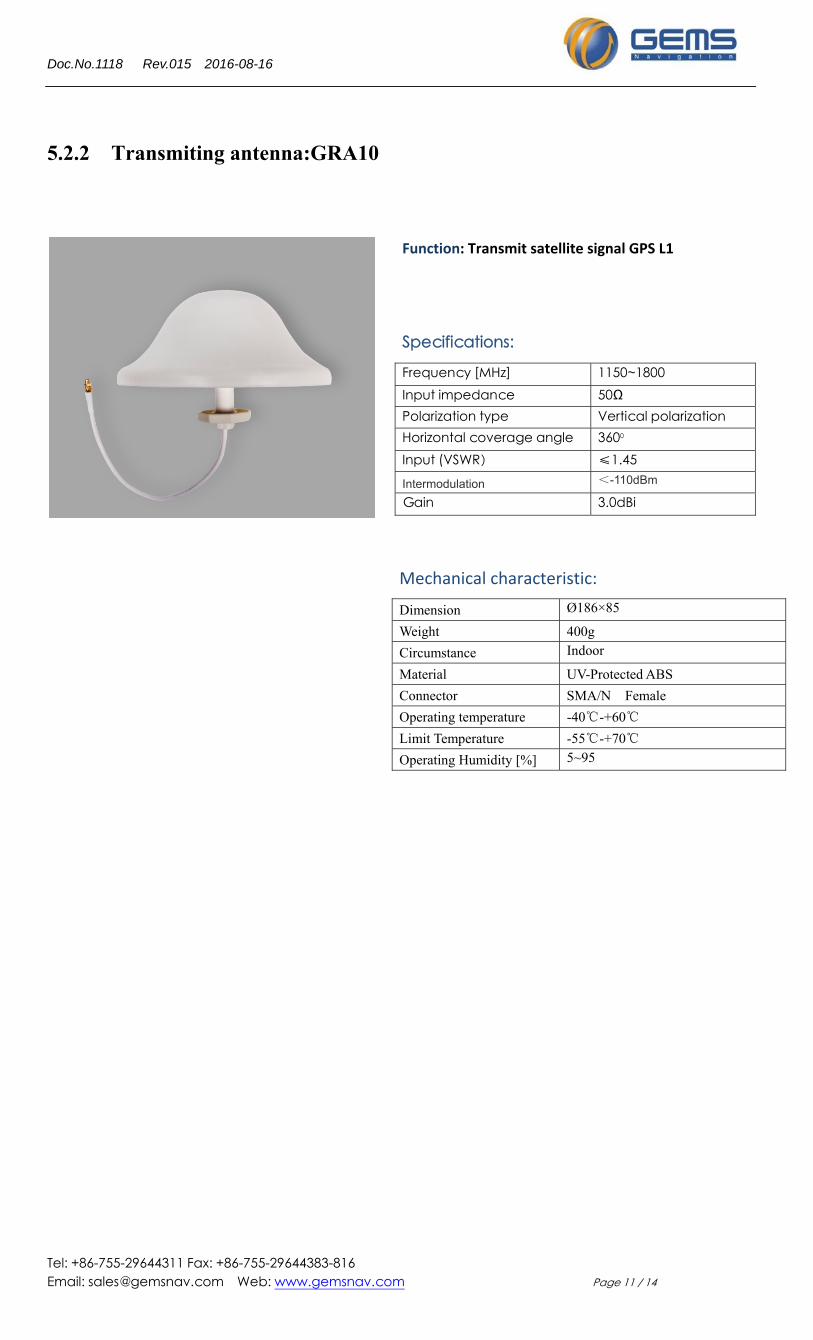
5.2.2 Transmiting antenna:GRA10
Function: Transmit satellite signal GPS L1
Specifications:
Frequency [MHz] 1150~1800Input impedance 50Ω Polarization type Vertical polarizationHorizontal coverage angle 3600 Input (VSWR) ≤1.45 Intermodulation <-110dBm
Gain 3.0dBi
Mechanical characteristic:
Dimension Ø186×85
Weight 400g
Circumstance Indoor
Material UV-Protected ABS
Connector SMA/N Female
Operating temperature -40℃-+60℃
Limit Temperature -55℃-+70℃
Operating Humidity [%] 5~95

Doc.No.1118 Rev.015 2016-08-16
Tel: +86-755-29644311 Fax: +86-755-29644383-816 Email: [email protected] Web: www.gemsnav.com Page 12 / 14
5.3 Cable Assembly
5.3.3 Select Connector
Connectors are industrial standard component, below are selectable:
5.3.1 RG8(KSR 400)
RG8,30M is usually used for connecting GPS antenna
TIMING4000 and lighting‐protector. You can calculate the length
according to your actual environment, also 60m or 90 be selected.
Connector N Male‐N Male.
The attenuation value is 0.2 dB/m; Thus, you can assess the
system, or contact with our sales to select proper configuration.
Tel:86‐755‐29644311
Fax:86‐755‐29644383‐816
Email:[email protected]
We apply two cable assembly,RG8,30M and KSR240,20M.
Please log in www.gemsnav.com, enter RG8 or KSR240,then you can
see the two cable’s technical specification.
RG8,30M
5.3.2 KSR 240
KSR240,20M is usually used to connect RGA30‐SV4 and GRA10.
The attenuation value 0.4dB/M.
Connector: N Male‐SMA Male.
Doc.No.1118 Rev.015 2016-08-16
Tel: +86-755-29644311 Fax: +86-755-29644383-816 Email: [email protected] Web: www.gemsnav.com Page 13 / 14
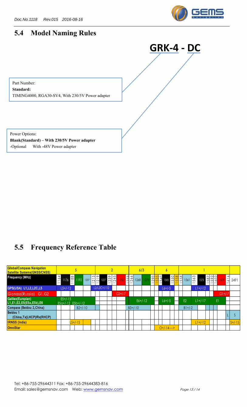
5.4 Model Naming Rules
5.5 Frequency Reference Table
Gllobal/Compass Navigation Satellite Systems(GNSS/CNSS)Frequency (MHz)
1164 1176
1188 1192 1207
1215
1219 1227
1239
1245 1252
1259
1266 1268 1278
1290
1535
1540 1545
1550
1558
1558 1561
1563 1575
1587
1592
1602 1609
1616 2491
GPS(USA) L1,L2,L2C,L5 Glonass(Russia) G1,G2
Galileo(Europian) E5+/-15L1,E1,E2,E5(E5a,E5b),E6 E5a+/-12 E5b+/-12Compass (Beidou 2,China) B3+/-10Beidou 1
(China,Tx(LHCP)/Rx(RHCP)IRNSS (India) L5+/-15 S+/-15OmniStar
L S
5 2 6/3 6 1
L6+/-5L2/L2C+/-12
B2+/-10
G2+/-7
E6+/-12 L6+/-5
L5+/-12 G1+/-7
O+/-14---->
E2 L1+/-17 E1
B1+/-2
L1+/-12
L1+/-12
Part Number:
Standard:
TIMING4000, RGA30-SV4, With 230/5V Power adapter
Power Options:
Blank(Standard) – With 230/5V Power adapter
-Optional With -48V Power adapter
GRK‐4 ‐ DC
Doc.No.1118 Rev.015 2016-08-16
Tel: +86-755-29644311 Fax: +86-755-29644383-816 Email: [email protected] Web: www.gemsnav.com Page 14 / 14
6.Typical faults and solutions
GPS repeater GRK‐4 fault location and remove:
First: Check the adapter of RGA30‐SV4 whether it connects to the power supply and power‐up to RGA30‐SV4. You can test the voltage between input axis and shell, if it’s about 5V,power supply was ok, RGA30‐SV4 was also works ok. Or else, check the power socket to assure the contact was ok.
Second: If it’s 5V at the input of Gain Controller, you need to check whether the fixing is steady between GRA10 and the cable.
Third: If the below two step were ok, please check the outdoor antenna TIMING4000 .You can, check the voltage between axis of the cable connector and the outer shielding layer to make sure it’s 5V.If no voltage, the circuit has fault, please contact our technical support. If 5V,the antenna TIMING4000 can be suspected.(In fact, this case hasn’t appear in our engineering projects.
Contact:
Tel:+86-755-29644311
Fax:+86-755-29644383 ext 816
Email:[email protected]
WWW.GEMSNAV.COM