116 428 jones boulevard • limerick airport business center ...€¦ · 116 428 jones boulevard...
TRANSCRIPT

116 428 Jones Boulevard • Limerick Airport Business Center • Pottstown PA • 19464 • Tel: 610-495-5131 • Fax: 610-495-5134www.watsonmcdaniel.com
PILO
T-O
PERA
TED
REG
ULAT
ING
VAL
VES

117428 Jones Boulevard • Limerick Airport Business Center • Pottstown PA • 19464 • Tel: 610-495-5131 • Fax: 610-495-5134www.watsonmcdaniel.com
Pilot-Operated Regulating Valves
PILOT-O
PERATEDREG
ULATING
VALVES

PILOT-OPERATED REGULATORSPilot-Operated Regulators are more accurate and offer higher capacities than standard direct-operated regulators.They will maintain constant set outlet pressure even when inlet pressure fluctuates or variations in flow occur. With theproper selection of pilots, these regulators will accurately control temperature, pressure, or a combination of both.
HD-Series Steam Service The HD-Series Regulator features Ductile Iron construction for increased pressure & temperature rating, a large full-port strainer with blow-down valve on pilot adapter which keeps dirt from entering control pilots, and field reversible pilot-mounting for versatile and easy installation.
HD Series Pilot-Operated Regulating Valve 120-123
PILOTS for HD Regulators 124-135
“P” & “P5” Pressure Pilots - The “P” is the standard spring-loaded pressure pilot. 124The “P5” is used for special applications requiring 0.5 PSI accuracy.
“BP” Back Pressure Pilot - Controls system back pressure. 125
“T” Temperature Pilot - Used for controlling temperature. 126-127
“A” Air Pilot - Normally used for controlling steam pressure using an air signal. 128-129Also used for temperature control when used in conjunction with the “PTR”or “PTL” temperature controller.
“PTR” & “PTL” Temperature Controllers (used with “A” Air Pilot) - The “PTR” or “PTL” will control 130-131a wider temperature range than the standard “T” Pilot.
“TRP” Temperature Pilot - Special purpose temperature pilot for controlling low temperatures 132outside the range of the standard “T” Pilot. Also available with special sensing bulbs.
“S” Solenoid Pilot - Used in conjunction with any of the above pilots for electrical on/off 133control of HD Regulators.
“DP” DP Pilot - Differential Pressure pilot – used when trying to balance two different 134media sources that are being blended
Over Pressure Protection Methods 135
HD Series Pilot-Operated Regulators
DUCTILE IRON BODY
HD Regulators are used in conjunction with theappropriate Pilot(s) to control Steam Pressure or Process Temperature
Page No.
118 428 Jones Boulevard • Limerick Airport Business Center • Pottstown PA • 19464 • Tel: 610-495-5131 • Fax: 610-495-5134www.watsonmcdaniel.com
PILO
T-O
PERA
TED
REG
ULAT
ING
VAL
VES
119428 Jones Boulevard • Limerick Airport Business Center • Pottstown PA • 19464 • Tel: 610-495-5131 • Fax: 610-495-5134www.watsonmcdaniel.com
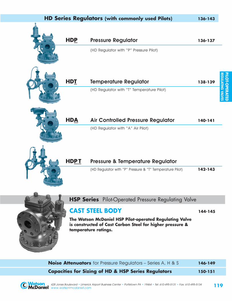
HD Series Regulators (with commonly used Pilots) 136-143
HDP Pressure Regulator 136-137
(HD Regulator with “P” Pressure Pilot)
HDT Temperature Regulator 138-139
(HD Regulator with “T” Temperature Pilot)
HDA Air Controlled Pressure Regulator 140-141
(HD Regulator with “A” Air Pilot)
HDPT Pressure & Temperature Regulator (HD Regulator with “P” Pressure & “T” Temperature Pilot) 142-143
HSP Series Pilot-Operated Pressure Regulating Valve
Noise Attenuation - Reduces noise in pressure reducing applications 148-151
CAST STEEL BODY 144-145
The Watson McDaniel HSP Pilot-operated Regulating Valve is constructed of Cast Carbon Steel for higher pressure &temperature ratings.
Noise Attenuators for Pressure Regulators – Series A, H & S 146-149
Capacities for Sizing of HD & HSP Series Regulators 150-151
PILOT-O
PERATEDREG
ULATING
VALVES

120 428 Jones Boulevard • Limerick Airport Business Center • Pottstown PA • 19464 • Tel: 610-495-5131 • Fax: 610-495-5134www.watsonmcdaniel.com
Model HD-Series Sizes 1/2” – 6”Connections Threaded 1/2” - 2”
Flanged 150# 1” - 6”Flanged 300# 1” - 6”
Body Material Ductile IronPMO Max. Operating Pressure 300 PSIGDesign Pressure/ NPT 450 PSIG @ 650˚ FTemperature Ratings 150# FLG 150 PSIG @ 566˚ FTMA/PMA 300# FLG 450 PSIG @ 650˚ F
FEATURES•No external power source is required.
This simplifies the valve and minimizesinstallation and maintenance costs.
•Pressure and temperature pilots can be usedin combination eliminating the need for a separate pressure and temperature regulator
•Ductile iron for higher pressure ranges andincreased safety. Ductile Iron is a better choicethan cast iron for steam applications.
• Full port strainer and blowdown valve on pilot adapter for ultimate protection againstdirt and scale
•Hardened stainless steel trim (55 Rc) forextended life even in the most demandingapplications
•The innovative design allows the pilot to bemounted on either side of the regulator and is easily field reversible
•Comes fully assembled with tubing and pilotadapter. The control pilot requires only fourbolts to complete the installation.
Ductile Iron
Ductile Iron BodyRight or LeftPilot MountingAvailable(Non-standardleft mountedshown)*
HardenedSST (55 Rc)Seat & Disk
Springprotectedfrom steam
Full Port PilotStrainer withbuilt-inBlowdownValveSelf-cleaning
stem guide
High Tensile Diaphragm
INLET
* Standard pilot mounting ison the right side of theregulator when lookinginto the outlet port. Pilotmounting on HDregulators are fieldreversible.
HD SeriesR E G U L A T O R S
Pilot-Operated Regulating Valve
• Ductile Iron body for higher pressures• Full port strainer & blowdown
valve on pilot adapter for ultimateprotection from dirt & scale
• Hardened stainless steel trimfor extended life
• Pre-mounted tubing & field reversible pilot adapter
• Optional reduced port trim• Low differential pressure option• Low inlet pressure option
TYPICAL APPLICATIONSThe Watson McDaniel HD-Series pilot operated regulators weredesigned for extremely accurate control of temperature and pressure in steam service applications. The HD-Series is made ofDuctile-iron for extended pressure and temperature ratings. Theseregulators use several different control pilots, which can be attachedto the valve to control pressure, temperature, or a combination ofboth. The different control pilots can be added or removed from theregulator body. This modular design adds to the versatility of thisproduct. The most common options include the P-Pilot for pressurereducing, and the T-Pilot for temperature control.
PILO
T-O
PERA
TED
REG
ULAT
ING
VAL
VES

HD SeriesR E G U L A T O R S
Pilot-Operated Regulating Valve
TYPICAL PILOTS
PRESSUREPilot
SOLENOIDPilot
TEMPERATUREPilot
AIRPilot
CONTROL PILOTSPi lo t Mount ingStandard pilot mounting is on the right side of the regulatorwhen looking into the outlet port (see diagrams onnext page which are all right mounted). For opposite mounting, please specify when ordering. Pilot mountingon HD regulators are field reversible.
PressureWhen controlling pressure there are several options you can usefor a pilot. The P-Pilot and the P5-Pilot are both spring adjustedpressure pilots. The P-Pilot is used on typical general-purposepressure reducing applications. The P5-Pilot is used when higheraccuracy is required and is capable of maintaining a controlpressure window of less then 1 PSI. The A-Pilot is air controlledand generally used when adjustment of the regulator andpressure reducing station is done remotely.
TemperatureThe T-Pilot is used to control temperature. The T-Pilot is filled with a temperature sensitive liquid, which expands when heated.The expansion of this liquid actuates a bellows that controls the temperature-regulating valve. The T-Pilot is equipped with an overheat bellows that protects the pilot in case of an overtemperature condition. The T-Pilot controls temperature through a range of 60-260˚F. Spec: ANSI/FCI 70-2 Class IV shut-off.
COMBINATION PILOTSOne of the advantages of the HD-Series regulating valve is that it can be used with many different variations of control pilots.Up to three pilots can be used simultaneously to control theoperation of these valves. The most common is the “PT” Pressure-Temperature combination pilots. In addition to these pilots beingused together the S-Solenoid Pilot can be used for turning thesystem on and off. (See next page for combination examples.)
On-Of fOn-off control of the regulator is possible by using the S-SolenoidPilot. The S-Pilot allows the regulator to be shut off or turned on electrically. Normally the regulator is equipped with either a P-Pressure Pilot or T-Temperature Pilot in addition to the S-Solenoid Pilot.
Pressure-TemperatureThe PT-Pilot combination is used when it is desirable to control boththe pressure and temperature of a system with only one regulatingvalve. The unique features of this modular valve allow this to beaccomplished quite easily. When the PT-Pilot combination is used, thedownstream pressure is limited to a maximum setting by the pressurepilot, while the temperature pilot maintains the correct temperature.
Back PressureWhen controlling the back pressure in a steam system, the BP-Pilot is used in conjunction with the HD-Series Regulator. This controls the pressure on the upstream side of the regulator.
Di f ferent ia l Pressure The DP-Pilot is used when trying to balance two different mediasources that are being blended.
121428 Jones Boulevard • Limerick Airport Business Center • Pottstown PA • 19464 • Tel: 610-495-5131 • Fax: 610-495-5134www.watsonmcdaniel.com
Watson McDaniel reserves theright to change the designsand/or materials of itsproducts without notice.©2010 Watson McDaniel Company
TYPICAL APPLICATIONS
• Pressure Regulating• Temperature Regulating• Pressure-Temperature Control• Back Pressure Control• Differential Pressure Control
PILOT-O
PERATEDREG
ULATING
VALVES

HD SeriesR E G U L A T O R S
Pilot-Operated Regulating Valve
OTHER PILOT CONFIGURATIONSUSED WITH HD REGULATOR• Air / Solenoid
• Air / Pneumatic Temperature Controller
• Air / Solenoid / Pneumatic TemperatureController
• Back Pressure
• Back Pressure / Solenoid
• Differential Pressure
Watson McDaniel’s Pilots will fit otherManufacturers’ Regulators.
TYPICAL REGULATOR & PILOT COMBINATIONSHDA
Regulatorwith
Air Pilot
HDPRegulator
with Pressure Pilot
HDTRegulator
with Temperature
Pilot
HDSRegulator
with Solenoid Pilot
HDPSRegulator
with Pressure & Solenoid
Pilots
HDTSRegulator
withTemperature &Solenoid Pilots
HDPTRegulator
with Pressure &Temperature
Pilots
HDPTSRegulator
with Pressure,
Temperature &Solenoid Pilots
122 428 Jones Boulevard • Limerick Airport Business Center • Pottstown PA • 19464 • Tel: 610-495-5131 • Fax: 610-495-5134www.watsonmcdaniel.com
Watson McDaniel reserves theright to change the designs
and/or materials of itsproducts without notice.
©2010 Watson McDaniel Company
PILO
T-O
PERA
TED
REG
ULAT
ING
VAL
VES

Option: Stainless diaphragms and external tubing - consult factory
123
HD SeriesR E G U L A T O R S
Pilot-Operated Regulating Valves
MATERIALSBody Ductile IronCover Ductile IronGasket Grafoil Cover Screws SteelPilot Adapter Ductile Iron/Cast SteelScreen Stainless SteelTubing CopperValve Seat Hardened SST (55Rc)Valve Disc Hardened SST (55Rc)Diaphragm Phosphor Bronze
HOW TO ORDERREGULATOR BODYSpecify: • HD regulator body
• Regulator size or capacity of steam required• End connections
(threaded, 150/300# flanged)
PILOT REQUIRED TO OPERATE THIS VALVENote: See “How to Order” in specific Pilot Section• T Temperature Pilot• P Pressure Pilot• A Air Pilot• S Solenoid Pilot• BP Back Pressure Pilot• PD Differential Pressure
HD-Ser ies DIMENSIONS – inches / pounds
(A) Face-To-Face Weight (lbs)Size NPT 150# 300# B C D NPT 150# 300#1/2” 43/8 51/2 33/8 61/2 183/4” 43/8 51/2 33/8 61/2 181” 53/8 51/2 6 61/4 31/2 7 23 40 45
11/4” 61/2 73/8 47/8 83/4 4311/2” 71/4 67/8 73/8 73/8 47/8 83/4 43 55 60
2” 71/2 81/2 9 81/4 53/8 107/8 65 75 8521/2” 93/8 10 9 53/4 113/4 100 105
3” 10 103/4 87/8 63/4 131/4 130 1454” 117/8 121/2 107/8 71/2 143/4 215 2356” 151/8 16 141/8 10 193/4 420 470
MINIMUM OPERATING PRESSURES
Minimum Inlet Pressure (for Valve):15 PSIG (Standard Main Valve)5 PSIG (Low Pressure Main Valve)
Minimum Differential Pressure (for Valve):*10 PSI (Standard Main Valve)3 PSI (Low Pressure Main Valve)
* Not required for Temperature Pilot applications
AFLG
ANPT
C
B
D
FLOW
OUT
Standard pilot mounting is onthe right side of the regulatorwhen looking into the outletport (as shown). Pilotmounting on HD regulators are field reversible.
428 Jones Boulevard • Limerick Airport Business Center • Pottstown PA • 19464 • Tel: 610-495-5131 • Fax: 610-495-5134www.watsonmcdaniel.com
Pilot mountingsurface
PILOT-O
PERATEDREG
ULATING
VALVES

124
“P” & “P5” PilotP I L O T S
MATERIALSPilot Body & Cover Ductile Iron or Cast SteelGasket GrafoilDiaphragm Phosphor BronzeHead & Seat Assembly Hardened SST (55 Rc)
Pressure Pilot• Max Inlet Pressure: 300 PSIG• Reduced Outlet Pressure Range: 3-200 PSIG• Minimum Inlet Pressures:
15 PSIG when used with standard main valve5 PSIG when used with low pressure main valve
• P-Pilot (Standard) + 1 PSIG accuracy
• P5-Pilot (Special) + 0.5 PSIG accuracy
PRESSURE-ADJUSTING SPRING RANGES“P” Pressure Range “P5” Pressure Range Identifying Colors
3-25 PSIG 1-10 PSIG yellow20-100 PSIG 10-25 PSIG blue80-200 PSIG – red
TYPICAL APPLICATIONSThe “P” & “P5” Pressure Pilots are used with the HD Regulatorto control steam pressure in steam mains or for processequipment. Pilot operated regulators will maintain constantdownstream pressure even when the inlet pressure to the valvefluctuates or steam usage varies.
FEATURES• The “P” Pilot can maintain downstream pressure to ±1 PSIG• “P5” Pilot can maintain downstream pressure to ±0.5 PSIG• Choices of three overlapping pressure ranges• Pressure control spring can be changed in line• Pilot is easily installed using only four bolts• Full port strainer and blowdown valve on pilot adapter for
ultimate protection from dirt and scale• Can be used with temperature and solenoid control pilot• Solid floating diaphragm is more failure resistant• Watson McDaniel's pilots can be used with other
manufacturers’ regulators
OPTIONS• Pressure pilot can be used with temperature pilot to eliminate
the need for two separate regulators• Solenoid pilot can be added for remote on/off control
of regulator• “P5” Pilot will maintain + 0.5 PSIG accuracy
HOW TO ORDER“P”, “P5” PRESSURE PILOTSpecify: • Reduced pressure range – Example: “P” Pilot at 3-25 PSIG, yellow
REGULATOR BODYSpecify: • HD regulator body
• Regulator size or capacity• End connections (threaded, 150/300# flanged)
91/2
5
Pressure Pilot for HD Regulating Valves
Steam Sensing LineConnection1/4” NPT
12
8 “P5”
428 Jones Boulevard • Limerick Airport Business Center • Pottstown PA • 19464 • Tel: 610-495-5131 • Fax: 610-495-5134www.watsonmcdaniel.com
MINIMUM OPERATING PRESSURESMinimum Inlet Pressure:
15 PSIG (Standard Main Valve)5 PSIG (Low Pressure Main Valve)
Minimum Differential Pressure:10 PSI (Standard Main Valve)
3 PSI (Low Pressure Main Valve)
Watson McDaniel reserves theright to change the designs
and/or materials of itsproducts without notice.
©2010 Watson McDaniel Company
“P”Units: inches
PILO
T-O
PERA
TED
REG
ULAT
ING
VAL
VES

125
“BP” PilotP I L O T S
Back PressurePilot• Max Inlet Pressure: 300 PSIG• Back Pressure Range: 10-200 PSIG• Minimum Inlet Pressures:
15 PSIG when used with standard main valve5 PSIG when used with low pressure main valve
HOW TO ORDER“BP” BACK PRESSURE PILOTSpecify: • Reduced pressure range – Example: “BP” Pilot at 20-100 PSIG, blue
REGULATOR BODYSpecify: • HD regulator body
• Regulator size or capacity• End connections (threaded, 150/300# flanged)
MATERIALSPilot Body & Cover Ductile IronGasket GrafoilDiaphragm Phosphor BronzeHead & Seat Assembly Hardened SST (55 Rc)
TYPICAL APPLICATIONSThe “BP” Back-Pressure Pilot used with the HD regulator,maintains upstream pressure in steam systems. These regulatorsare commonly used to supply flash steam to low pressure mains.
FEATURES•The “BP” Pilot can maintain upstream pressure to ±1 PSIG•Choices of three overlapping pressure ranges•Pressure adjusting spring can be changed with
regulator in line•Pilot is easily installed using only four bolts• Full port strainer and blowdown valve on pilot adapter for
ultimate protection from dirt and scale•Solid floating diaphragm is more failure resistant•Watson McDaniel's pilots can be used with other
manufacturers’ regulators
OPTIONS•Can be used with solenoid pilot for on/off control
PRESSURE-ADJUSTING SPRING RANGESPressure Range Identifying Colors
10-25 PSIG yellow20-100 PSIG blue80-200 PSIG red
91/2
5
Back Pressure Pilot for HD Regulating Valves
Steam Sensing LineConnection1/4” NPT
428 Jones Boulevard • Limerick Airport Business Center • Pottstown PA • 19464 • Tel: 610-495-5131 • Fax: 610-495-5134www.watsonmcdaniel.com
MINIMUM OPERATING PRESSURESMinimum Inlet Pressure:
15 PSIG (Standard Main Valve)5 PSIG (Low Pressure Main Valve)
Minimum Differential Pressure:10 PSI (Standard Main Valve)
3 PSI (Low Pressure Main Valve)
Units: inches
PILOT-O
PERATEDREG
ULATING
VALVES
126
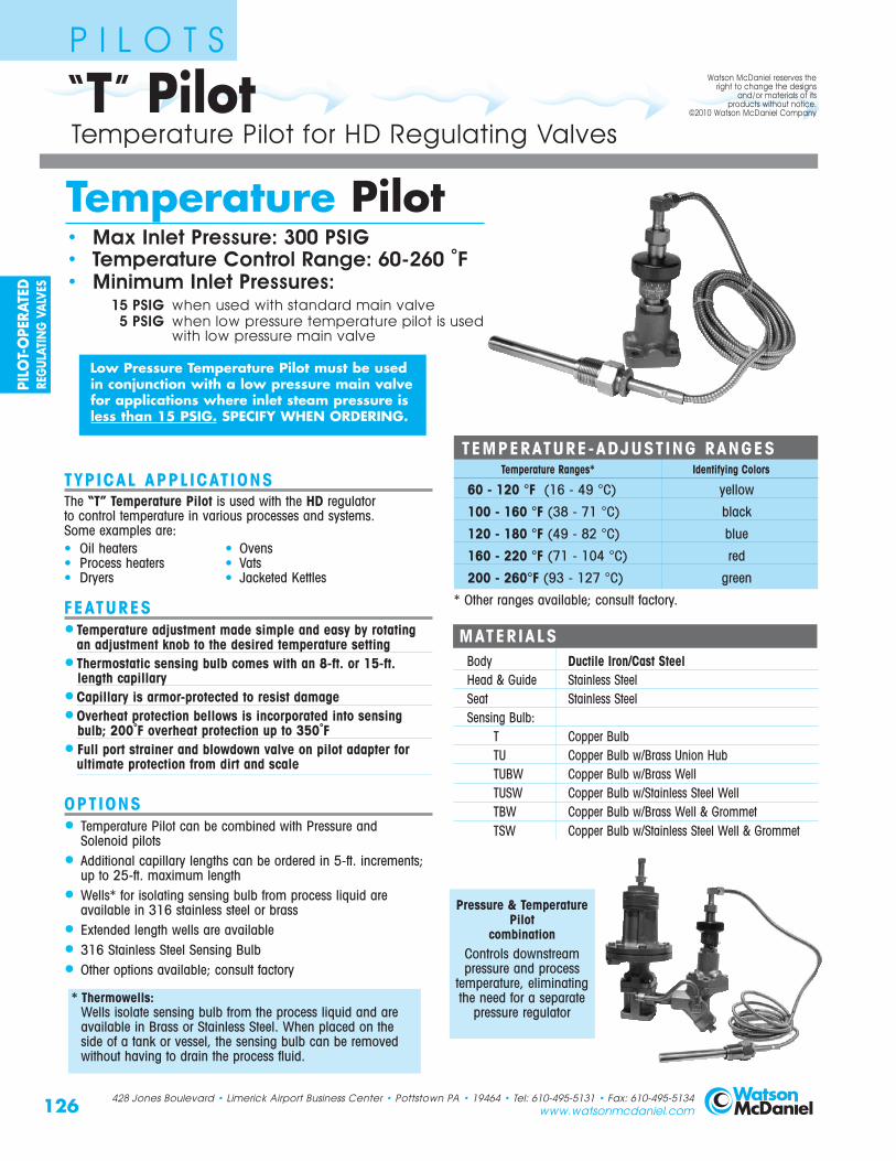
“T” PilotP I L O T S
TYPICAL APPLICATIONSThe “T” Temperature Pilot is used with the HD regulator to control temperature in various processes and systems. Some examples are:• Oil heaters • Ovens• Process heaters • Vats• Dryers • Jacketed Kettles
FEATURES•Temperature adjustment made simple and easy by rotating
an adjustment knob to the desired temperature setting• Thermostatic sensing bulb comes with an 8-ft. or 15-ft.
length capillary•Capillary is armor-protected to resist damage•Overheat protection bellows is incorporated into sensing
bulb; 200˚F overheat protection up to 350˚F• Full port strainer and blowdown valve on pilot adapter for
ultimate protection from dirt and scale
OPTIONS• Temperature Pilot can be combined with Pressure and
Solenoid pilots
• Additional capillary lengths can be ordered in 5-ft. increments;up to 25-ft. maximum length
• Wells* for isolating sensing bulb from process liquid are available in 316 stainless steel or brass
• Extended length wells are available
• 316 Stainless Steel Sensing Bulb
• Other options available; consult factory
MATERIALSBody Ductile Iron/Cast SteelHead & Guide Stainless SteelSeat Stainless SteelSensing Bulb:
T Copper BulbTU Copper Bulb w/Brass Union HubTUBW Copper Bulb w/Brass WellTUSW Copper Bulb w/Stainless Steel WellTBW Copper Bulb w/Brass Well & GrommetTSW Copper Bulb w/Stainless Steel Well & Grommet
Pressure & Temperature Pilot
combinationControls downstreampressure and process
temperature, eliminatingthe need for a separate
pressure regulator
TEMPERATURE-ADJUSTING RANGESTemperature Ranges* Identifying Colors
60 - 120 °F (16 - 49 °C) yellow
100 - 160 °F (38 - 71 °C) black
120 - 180 °F (49 - 82 °C) blue
160 - 220 °F (71 - 104 °C) red
200 - 260°F (93 - 127 °C) green
* Other ranges available; consult factory.
Temperature Pilot• Max Inlet Pressure: 300 PSIG• Temperature Control Range: 60-260 �F• Minimum Inlet Pressures:
15 PSIG when used with standard main valve5 PSIG when low pressure temperature pilot is used
with low pressure main valve
Temperature Pilot for HD Regulating Valves
428 Jones Boulevard • Limerick Airport Business Center • Pottstown PA • 19464 • Tel: 610-495-5131 • Fax: 610-495-5134www.watsonmcdaniel.com
Watson McDaniel reserves theright to change the designs
and/or materials of itsproducts without notice.
©2010 Watson McDaniel Company
Low Pressure Temperature Pilot must be usedin conjunction with a low pressure main valvefor applications where inlet steam pressure isless than 15 PSIG. SPECIFY WHEN ORDERING.
* Thermowells:Wells isolate sensing bulb from the process liquid and areavailable in Brass or Stainless Steel. When placed on the side of a tank or vessel, the sensing bulb can be removedwithout having to drain the process fluid.
PILO
T-O
PERA
TED
REG
ULAT
ING
VAL
VES

6 3/4
See bulbchart above
Diagram below shows “T” Pilot TU Option for Bulb
127
“T” PilotP I L O T S
HOW TO ORDER“T” TEMPERATURE PILOTSpecify:• Temperature range from the chart or indicate the
temperature of the process you wish to control• The length of capillary required; 8-ft. is standard• Bulb type needed:
T, TU, TUBW, TUSW, TBW & TSW
Example: TU, 8 FT CAP, 60-120˚F, yellow
REGULATOR BODYSpecify:• HD regulator body• Regulator size or capacity of steam required• End connections (threaded, 150/300# flanged)
T Plain copper bulb
TU Union connected copper bulb that can bescrewed into the side of tank* most common selection
TUBW Type TU bulb with a brass well. The well, whichisolates bulb from process fluid, can be placedin the side of a tank allowing the sensing bulb tobe removed without having to drain the tank ofliquid
TUSW Type TU bulb with a corrosion resistant stainlesssteel well. The well, which isolates bulb fromprocess fluid, can be placed in the side of a tankallowing the sensing bulb to be removed withouthaving to drain the tank of liquid
TBW Type T bulb with an extended length brasswell. The extended well allows deeper insertionof sensing bulb into tanks.
TSW Type T bulb with extended length stainlesssteel well. The extended well allows deeperinsertion of sensing bulb into tanks.
Other options available; consult factory.
SENSING BULBS AVAILABLE
T 81/2
5/8
TU51/2
5/8
TUBW 57/8
3/4
TUSW 61/8
3/4
TBW 18
3/4
TSW 18
3/4
Temperature Pilot for HD Regulating Valves
Union Hub3/4” NPT
428 Jones Boulevard • Limerick Airport Business Center • Pottstown PA • 19464 • Tel: 610-495-5131 • Fax: 610-495-5134www.watsonmcdaniel.com
*Most common
MINIMUM OPERATING PRESSURESMinimum Inlet Pressure:
15 PSIG (Standard Main Valve)5 PSIG (Low Pressure Main Valve with
Low Pressure Temperature Pilot)
Low Pressure Temperature Pilot must be used in conjunction with a Low Pressure Main Valve for applications where inlet steam pressure is below 15 PSIG. SPECIFY WHEN ORDERING.
3/4” NPT
3/4” NPT
3/4” NPT
3/4” NPT
3/4” NPT
Units: inches
UnionNut
Units: inches
PILOT-O
PERATEDREG
ULATING
VALVES

128
“A” PilotP I L O T S
TYPICAL APPLICATIONSThe “A” Air Pilot is used with the HD Regulator to control steam pressure on steam mains and process equipment. The “A” Air Pilot can also be used in conjunction with the PTL or PTR pneumatic temperature controllers for controllingtemperature in process applications. The principal advantagethe “A” Air Pilot over standard spring loaded pilots is thatpressure adjustments to the regulator can be made from a remote location. A regulator that is placed in a difficult to reach or inaccessible location can be adjusted by a remotecontrol panel board placed in an accessible location.
HOW IT WORKSWhen air pressure is applied to the upper chamber of the air pilot it exerts a downward force on the air pilot’s diaphragm. This force controls the outlet pressure of the steam through the regulating valve. The control process is similar to a springloaded pressure pilot except that the air pressure takes the placeof the spring. There are three separate models of air pilots thatmake up the complete range depending on the steam pressurethat needs to be controlled and the control air pressure available.See Pressure Adjusting Ranges chart.
FEATURES• Pressure adjustments to the regulator can be done from
a remote location using an air signal• Air-operated pilot ensures instant response and extremely
accurate control• Full port strainer and blowdown valve on pilot adapter for
ultimate protection from dirt and scale• Controls pressure settings within ±1 PSIG
PRESSURE ADJUSTING RANGESModel Pressure DescriptionRanges
A1 3-125 PSIG 1:1 ratio of steam pressureto control air pressure
A4 3-200 PSIG 4:1 ratio of steam pressureto control air pressure
A6 20-200 PSIG 6:1 ratio of steam pressureto control air pressure
MATERIALSPilot Body & Cover Ductile IronGasket GrafoilCover Screws Steel, GR5Head & Seat Assembly Hardened SST (55 Rc)
Air Pilot• Max Inlet Pressure: 300 PSIG• Reduced Outlet Pressure Range: 3-200 PSIG• Minimum Inlet Pressures:
15 PSIG when used with standard main valve5 PSIG when used with low pressure main valve
Note: Temperature Range: 0-350 �F when used with PTL & PTR temperature controllers
DIMENSIONS – inchesModel A B
A1 51/4 5
A4 51/4 77/8
A6 51/4 91/2
B
A
Air Pilot for HD Regulating Valves
Steam Sensing LineConnection1/4” NPT
Control Air Connection1/4” NPT
The larger Diaphragm area of the “A4” & “A6” Air Pilots allow the use of lower control air pressure to regulate higherpressure steam.
428 Jones Boulevard • Limerick Airport Business Center • Pottstown PA • 19464 • Tel: 610-495-5131 • Fax: 610-495-5134www.watsonmcdaniel.com
MAXIMUM CONTROL AIR PRESSURE ON AIR PILOT IS 125 PSIG
Controls Pressure & Temperature
Watson McDaniel reserves theright to change the designs
and/or materials of itsproducts without notice.
©2010 Watson McDaniel Company
PILO
T-O
PERA
TED
REG
ULAT
ING
VAL
VES

129
“A” PilotP I L O T S
HOW TO ORDER“A” AIR PILOTSpecify:• Air Pilot A1, A4 or A6• Remote Control Panel Board
PL1, PL2 or PL3
REGULATOR BODYSpecify:• HD regulator body• Regulator size or capacity and pressure range
of steam required• End connections (threaded, 150/300# flanged)
REMOTE CONTROL PANEL BOARDSThree different options of remote control panel boards can be used alongwith the "A" Air Pilots. Supply air is fed directly through the control panelboard to the air pilot. You can choose one of the three options of controlpanel boards when using the air piloted regulators. Minimum 5 PSIG airsupply pressure is required.
PL1The PL1 is made up of an air pressure regulator with adjustment knoband pressure gauge that measures the amount of air pressure going to the pilot (air signal). Steam pressure of the system is controlled byadjusting the air pressure regulator.
PL2The PL2 is the same as the PL1 with the addition of an extra air pressuregauge for measuring the air supply pressure to the control panel board.
PL3The PL3 is the same as the PL2 with the addition of a Steam Pressure Gauge for measuring steam pressure on the outlet side of the regulating valve.
DESCRIPTION OF OPERATIONThe “A” Air Pilot is being used in conjunctionwith the PL2 Control Panel Board to regulatesteam pressure. A small air regulator on thepanel board can be adjusted to control the airpressure to the pilot. One gauge on the panelboard measures air line pressure to the panelboard and the other gauge shows the airpressure being sent to the pilot. Steam pressureat the outlet of the regulator is controlled by theair pressure signal to the pilot. Depending onthe air pilot model chosen (A1, A4, A6), therewill be a 1:1, 4:1, or 6:1 ratio of outlet steampressure to air pressure.
AIR SUPPLY
SENSING LINESLOPED DOWN
FROM PILOT
OUTLET STEAM
AIR SIGNAL(control air)
INLETSTEAM
Air Pilot for HD Regulating Valves
PL1 PL3PL2
AIR SIGNAL AIR SUPPLY
AIR SIGNAL
AIR SUPPLY
STEAM PRESSURE
AIR SIGNAL
FLOWHDA
(REGULATORwith AIR PILOT)
PL2BYPASS
STEAM TRAP
Pressure Reducing Station Using HD Regulator with an Air Pilot
428 Jones Boulevard • Limerick Airport Business Center • Pottstown PA • 19464 • Tel: 610-495-5131 • Fax: 610-495-5134www.watsonmcdaniel.com
Controls Pressure & Temperature
MINIMUM OPERATING PRESSURESMinimum Inlet Pressure:
15 PSIG (Standard Main Valve)5 PSIG (Low Pressure Main Valve)
Minimum Differential Pressure:10 PSI (Standard Main Valve)
3 PSI (Low Pressure Main Valve)
CONTROL AIR PRESSURE RANGEA-Pilot Control Pressure:
3-125 PSIG (depending on pilot selected and desired outlet pressure)
REGULATIN
G VALVES
AIR PILOT
HD REGULATOR
PILOT-O
PERATEDREG
ULATING
VALVES

130
PTL(mounts directly on
tank or vessel)
PTR(mounts remotely
with 4-ft. Capillary)
PTL & PTR ControllerP I L O T S
TYPICAL APPLICATIONSThe PTL and PTR Pneumatic Temperature Controllers operate over a wider temperature range than our standard “T” temperature pilot. These temperature controllers also react quicker totemperature change which make them an excellentchoice for instantaneous hot water applications.
HOW IT WORKSThe PTL and PTR Pneumatic Temperature Controllers are used in conjunction with an “A” Air Pilot to control the operation of the HDRegulator. The PTL uses a bimetallic element to sense temperature and the PTR uses a hydraulically filled bulb with a 4-ft. capillary to sense temperature.The air supply is connected to the inlet of the controllerand the air output signal is fed directly to an Air Pilot,which controls the opening and closing of the steamregulating valve.
FEATURES• Accurate and rapid response to temperature
changes• Covers control temperature range of 0-350 ˚F
Model PTL PTRTemperature Adjustment Range 50 - 350 ˚F 0 - 300 ˚FMaximum Air Supply Pressure 35 PSIG 35 PSIGSensing Bulb Bi-Metallic Hydraulic Fill
Max. Pressure 250 PSIG 250 PSIGMax. Temperature 400˚F 350˚FMaterial Copper CopperOptional Material Stainless Steel Stainless SteelCapillary Length N/A 4-ft.
HOW TO ORDERPTL & PTR PNEUMATIC TEMPERATURE CONTROLLERSpecify: • PTL or PTR controller model (air pilot required for operation)
AIR PILOTSpecify: • A1, A4 or A6 Air Pilot model (refer to Air Pilot section)
REGULATOR BODYSpecify: • HD regulator body
• Regulator size or capacity• End connections (threaded, 150/300# flanged)
Pneumatic Temperature Controller (used with Air Pilot)
Pneumatic TemperatureController• Max Inlet Pressure: 300 PSIG• Temperature Range: PTR: 0-300 �F
PTL: 50-350 �F• Minimum Inlet Pressures:
15 PSIG when used with standard main valve5 PSIG when used with low pressure main valve
428 Jones Boulevard • Limerick Airport Business Center • Pottstown PA • 19464 • Tel: 610-495-5131 • Fax: 610-495-5134www.watsonmcdaniel.com
MINIMUM OPERATING PRESSURESMinimum Inlet Pressure:
15 PSIG (Standard Main Valve)5 PSIG (Low Pressure Main Valve)
Watson McDaniel reserves theright to change the designs
and/or materials of itsproducts without notice.
©2010 Watson McDaniel Company
PILO
T-O
PERA
TED
REG
ULAT
ING
VAL
VES

131
Model PTL (direct mounted)
Model PTR (remote mounted)
DESCRIPTION OFOPERATIONThe PTL Pneumatic TemperatureController senses outlet watertemperature on a semi-instantaneous hot water heater.When the outlet water temperaturefalls below the set point, the PTLpneumatic temperature controllersends an air signal to the A1 AirPilot which opens the regulator,allowing steam to heat the tank.When the water reaches thedesired set temperature, the PTLpneumatic temperature controllershuts off the air signal to the A1Air Pilot and the regulator closes,cutting off steam to the heater.
PTL & PTR ControllerP I L O T S
Pneumatic Temperature Controller (used with Air Pilot)
SERIES HDA-PTLPNEUMATIC
TEMPERATUREREGULATOR
STEAMINLET
BYPASS LINE
SEMI-INSTANTANEOUSHEATER
COLD WATERINLET
“PTL”CONTROLLER
AIRINLET
AIRREGULATOR
HOTWATEROUTLET
AIRSIGNALLINE
WELL
111/8
3/4” NPT
7/8
111/2
11/2
3 5/8
2-1/4
3 5/16
23/4
WITH RELAY
WELL
3/4” NPT
61/2
STAINLESS STEEL
51/4
1/8”NPT 21/8
13/32
COPPER
27/8
1/8”NPT
111/8
428 Jones Boulevard • Limerick Airport Business Center • Pottstown PA • 19464 • Tel: 610-495-5131 • Fax: 610-495-5134www.watsonmcdaniel.com
TEMPERATURE SET POINT ADJUSTMENT KNOB
TEMPERATURE SET POINT ADJUSTMENT KNOB
Units: inches
PILOT-O
PERATEDREG
ULATING
VALVES
VACUUMBREAKER
AIRVENT
STEAMTRAP

132
“TRP” PilotP I L O T S
Temperature Pilot• Max Inlet Pressure: 300 PSIG• Temperature Control Range: 20-250 �F• Min Inlet Pressures: 15 PSIG standard main valve
5 PSIG low pressure main valve
HOW TO ORDER“TRP” TEMPERATURE PILOTSpecify:• Temperature range from the chart or indicate the temperature
of the process you wish to control• The length of capillary required
REGULATOR BODYSpecify:• HD regulator body• Regulator size or capacity of steam required• End connections (threaded, 150/300# flanged)
A
B
C
4” minimumlength
D
E
1” NPT1” NPT
Hub
DIMENSIONS – inchesStd. Bulb Bulb Bulb Body Height Thermowell or
Range Length Diameter C Separable Socket˚F A B w/Dial w/o Dial D E
40-65° 121/4 1.0 111/4 1611/64 13 1.165-85° 121/4 1.0 111/4 1611/64 13 1.185-110° 121/4 1.0 111/4 1611/64 13 1.1110-135° 121/4 1.0 111/4 1611/64 13 1.1135-160° 121/4 1.0 111/4 1611/64 13 1.1160-190° 121/4 1.0 111/4 1611/64 13 1.1190-210° 121/4 1.0 111/4 1611/64 13 1.1210-245° 121/4 1.0 111/4 1611/64 13 1.1245-275° 121/4 1.0 111/4 1611/64 13 1.1275-310° 121/4 1.0 111/4 1611/64 13 1.1305-365° 121/4 1.0 111/4 1611/64 13 1.1365-415° 121/4 1.0 111/4 1611/64 13 1.1415-435° 121/4 1.0 111/4 1611/64 13 1.1
MATERIALSPilot Body Ductile IronValve and Seat Stainless steel
Support Bracket AluminumBulb & Capillary Copper (optional stainless steel)All Other Parts Brass
Temperature Pilot for HD Regulating Valves
THERMOWELL
TYPICAL APPLICATIONSThe “TRP” Temperature Pilot is used with the HD Regulator tocontrol temperature in various processes and systems. Someexamples are: Oil heaters, Ovens, Process Heaters, Vats, Dryers and Jacketed Kettles.
FEATURES• Ductile Iron pilot body• Stainless steel valve and seat• Standard capillary is copper with 316 stainless steel
armor in 10 feet length
OPTIONS• Additional Capillary Length: Available up to 25-ft. in
5-ft. increments.• Special Materials: Sensing bulb, wells, and capillary are
available in special corrosion resistant materials.- 316 stainless steel capillary- 316 stainless steel armor with standard capillary- Kynar-covered capillary
• Finned Bulb: Special finned sensing bulb for improved temperature sensitivity when controlling air temperature in heating ducts
• Thermowell or Separable Socket: Available in stainless steel or copper
• Temperature Sensing Dial: Indicates temperature of process being controlled
428 Jones Boulevard • Limerick Airport Business Center • Pottstown PA • 19464 • Tel: 610-495-5131 • Fax: 610-495-5134www.watsonmcdaniel.com
Watson McDaniel reserves theright to change the designs
and/or materials of itsproducts without notice.
©2010 Watson McDaniel Company
The “TRP” will controllower temperaturesthan the standard “T” PilotPI
LOT-
OPE
RATE
DRE
GUL
ATIN
G V
ALVE
S

133
TYPICAL APPLICATIONSTypically used for automatic operation, remote control,programmed cycling, sequential function interlocks with otherequipment, and emergency shut-off in case of power failure.
HOW IT WORKSThe “S” Solenoid Pilot can be used in conjunction withPressure, Temperature, or Air Pilots to electrically control on/offoperation of the HD Regulator. When the solenoid pilot is used,the regulator can be turned on or off by electrically activatingor de-activating the solenoid.
Normally Closed (nc) – StandardThe normally closed Solenoid Pilot remains closed in the non-activated state. The regulating valve will remain closed until an electrical signal is sent to the solenoid pilot. This isknown as a fail-safe condition.
Normally Open (no) – OptionalThe normally opened Solenoid Pilot remains open in the non-activated state. The regulating valve will function normallyunless an electrical signal is used to shut-off the solenoid pilot.
FEATURES• Available normally opened (no) or normally closed (nc)• Full-port strainer and blow-down valve on pilot adapter to
eliminate failure caused by contaminated steam systems
OPTIONS• Normally open solenoid• NEMA Ratings: NEMA 4 and NEMA 7• Voltage: 24 VAC, 220 VAC, 240 VAC
STANDARD SOLENOID PILOTS AVAILABLESteam Inlet Pressure 0-180 PSIG
180-250 PSIGNEMA 1 – Standard
NEMA Ratings NEMA 4 – Waterproof (optional)NEMA 7 – Explosion-proof (optional)
Voltage 110 Volts AC (standard)24 Volts AC (optional)220 Volts AC (optional)240 Volts AC (optional)
MATERIALSPilot Body & Cover Ductile IronGasket GrafoilCover Screws Steel, GR5Internals Stainless Steel
HOW TO ORDER“S” SOLENOID PILOTSpecify: • Inlet Steam Pressure range:
0-180 PSIG or 180-250 PSIG• NEMA rating: NEMA 1, NEMA 4 or NEMA 7
(if not specified NEMA 1 Standard will be supplied) • Control Voltage: 24, 110, 220 or 240 VAC
REGULATOR BODYSpecify: • HD regulator body
• Regulator size or capacity of steam required• End connections (threaded, 150/300# flanged)
“S” PilotP I L O T S
SolenoidPilot•For Electrical On-Off Control
of Regulating Valves
•Max Inlet Pressure: 250 PSIG
Electric Pilot for On/Off Control of HD Regulating Valves
428 Jones Boulevard • Limerick Airport Business Center • Pottstown PA • 19464 • Tel: 610-495-5131 • Fax: 610-495-5134www.watsonmcdaniel.com
MINIMUM OPERATING PRESSURESMinimum Inlet Pressure:
15 PSIG (Standard Main Valve)5 PSIG (Low Pressure Main Valve)
Minimum Differential Pressure:10 PSI (Standard Main Valve)
3 PSI (Low Pressure Main Valve)
REGULATIN
G VALVES
PILOT-O
PERATEDREG
ULATING
VALVES
134 428 Jones Boulevard • Limerick Airport Business Center • Pottstown PA • 19464 • Tel: 610-495-5131 • Fax: 610-495-5134www.watsonmcdaniel.com
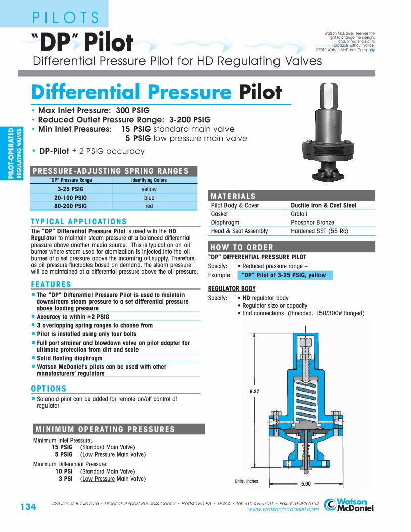
“DP” PilotP I L O T S
MATERIALSPilot Body & Cover Ductile Iron & Cast SteelGasket GrafoilDiaphragm Phosphor BronzeHead & Seat Assembly Hardened SST (55 Rc)
Differential Pressure Pilot• Max Inlet Pressure: 300 PSIG• Reduced Outlet Pressure Range: 3-200 PSIG• Min Inlet Pressures: 15 PSIG standard main valve
5 PSIG low pressure main valve
• DP-Pilot + 2 PSIG accuracy
TYPICAL APPLICATIONSThe “DP” Differential Pressure Pilot is used with the HDRegulator to maintain steam pressure at a balanced differentialpressure above another media source. This is typical on an oilburner where steam used for atomization is injected into the oilburner at a set pressure above the incoming oil supply. Therefore,as oil pressure fluctuates based on demand, the steam pressurewill be maintained at a differential pressure above the oil pressure.
FEATURES• The “DP” Differential Pressure Pilot is used to maintain
downstream steam pressure to a set differential pressureabove loading pressure
• Accuracy to within ±2 PSIG• 3 overlapping spring ranges to choose from• Pilot is installed using only four bolts• Full port strainer and blowdown valve on pilot adapter for
ultimate protection from dirt and scale• Solid floating diaphragm• Watson McDaniel's pilots can be used with other
manufacturers’ regulators
OPTIONS• Solenoid pilot can be added for remote on/off control of
regulator
HOW TO ORDER“DP” DIFFERENTIAL PRESSURE PILOTSpecify: • Reduced pressure range – Example: “DP” Pilot at 3-25 PSIG, yellow
REGULATOR BODYSpecify: • HD regulator body
• Regulator size or capacity• End connections (threaded, 150/300# flanged)
9.27
Differential Pressure Pilot for HD Regulating Valves
5.00
MINIMUM OPERATING PRESSURESMinimum Inlet Pressure:
15 PSIG (Standard Main Valve)5 PSIG (Low Pressure Main Valve)
Minimum Differential Pressure:10 PSI (Standard Main Valve)
3 PSI (Low Pressure Main Valve)
Watson McDaniel reserves theright to change the designs
and/or materials of itsproducts without notice.
©2010 Watson McDaniel Company
Units: inches
PRESSURE-ADJUSTING SPRING RANGES“DP” Pressure Range Identifying Colors
3-25 PSIG yellow20-100 PSIG blue80-200 PSIG red
PILO
T-O
PERA
TED
REG
ULAT
ING
VAL
VES

PRESSUREPILOT
2nd Stage HD REGULATOR
PRESSUREPILOT
(Monitor)MAINPRESSUREPILOT
INLET OUTLET
1st Stage HD REGULATOR
135428 Jones Boulevard • Limerick Airport Business Center • Pottstown PA • 19464 • Tel: 610-495-5131 • Fax: 610-495-5134www.watsonmcdaniel.com
Over Pressure Protection MethodsP I L O T S
Using “P” and “BP” Pilots
Back Pressure Regula tors fo r Boi ler Over load Pro tec t ionIn steam systems with several applications of varying importance, a back pressure regulator may be used to prevent overloading of theboiler by isolating non-essential loads from critical processes in the event steam demand exceeds boiler output. When steam demandis greater than the capacity the boiler can generate, pressure in the boiler will drop, possibly upsetting the control balance in the boilerresulting in the generation of wet steam. Using back pressure regulators on the non-essential application supply lines allows isolationof these applications at times of peak demand by shutting off steam flow to areas deemed non-essential. This ensures that boilerdemand is not exceeded and steam flow is maintained to critical processes until demand subsides and the boiler is able to catch up.
Pressure Overr ide Pro tec t ion o f Regula tor Supply L inesOn multi-stage pressure reducing applications where a rise in control pressure due to failure of the final supply regulator could result inequipment damage and/or personnel injury, a secondary pressure pilot may be added to provide override protection of a steam supplyline. During normal operation, the main pressure pilot on the 1st stage regulator provides intermediate pressure control while theadditional “monitor” pilot senses final control pressure and remains open due to a slightly higher setting than the final control pressuresetting. Should the 2nd stage regulator fail for any reason, increasing supply pressure will begin to close the monitor pressure pilot ofthe 1st stage regulator, thus overriding the main control pilot preventing final supply pressure from increasing. This overpressureprotection can similarly be offered on single-stage reducing valves by protecting against failure of the main control pilot.
STEAM TO ESSENTIAL SERVICES
FTT TRAP
PILOT-OPERATED BACK PRESSURE REGULATOR
BOILERSTEAMSUPPLY
DRIP PAN ELBOW
HEADER
SAFETYVALVE
PILOT-OPERATED PRESSURE REDUCINGAND BACK PRESSURE
REGULATOR
STEAM TO NON-ESSENTIALSERVICES
STEAM TO NON-ESSENTIALSERVICES
PILOT-O
PERATEDREG
ULATING
VALVES

136
HDPREGULATOR & PILOT
HD Regulating Valve with “P” Pressure Pilot• Max Inlet Pressure: 300 PSIG• Reduced Outlet Pressure Range: 3-200 PSIG• Min Inlet Pressures:
15 PSIG standard main valve5 PSIG low pressure main valve
TYPICAL APPLICATIONSThe HD Regulator with the “P” Pressure Pilot is usedfor reducing steam pressure in piping mains andprocess applications. Pilot-operated regulators willmaintain constant downstream pressure even when theinlet pressure to the regulator fluctuates or steam usagevaries.
FEATURES• The “P” Pilot can maintain downstream pressure
to ±1 PSIG• Optional “P5” pilot can maintain pressure
to ±0.5 PSIG• Choices of three overlapping pressure ranges• Pressure adjusting spring can be changed with
regulator in line• Pilot is easily installed using only four bolts• Full port strainer and blowdown valve on pilot
adapter for ultimate protection from dirt and scale• Watson McDaniel’s pilots can be used with other
manufacturers’ regulators
OPTIONS• Pressure and temperature pilots can be combined
on the same regulator• Solenoid pilot can be added for electrical on/off
control of the regulator• Can be used with solenoid and temperature pilots
PRESSURE-ADJUSTING SPRING RANGES “P”Pressure Ranges Identifying Colors
3-25 PSIG yellow20-100 PSIG blue80-200 PSIG red
PRESSURE-ADJUSTING SPRING RANGES “P5”1-10 PSIG yellow
10-25 PSIG blue
MATERIALSBody Ductile IronCover Ductile IronGasket GrafoilCover Screws SteelPilot Adapter Ductile Iron/Cast SteelScreen Stainless SteelTubing CopperValve Seat Hardened SST (55 Rc)Valve Disc Hardened SST (55 Rc)Diaphragm Phosphor Bronze
Pilot-Operated Pressure Regulating Valve
428 Jones Boulevard • Limerick Airport Business Center • Pottstown PA • 19464 • Tel: 610-495-5131 • Fax: 610-495-5134www.watsonmcdaniel.com
MINIMUM OPERATING PRESSURESMinimum Inlet Pressure:
15 PSIG (Standard Main Valve)5 PSIG (Low Pressure Main Valve)
Minimum Differential Pressure:10 PSI (Standard Main Valve)
3 PSI (Low Pressure Main Valve)
Watson McDaniel reserves theright to change the designs
and/or materials of itsproducts without notice.
©2010 Watson McDaniel Company
PILO
T-O
PERA
TED
REG
ULAT
ING
VAL
VES

137
HOW IT WORKSThe purpose of the pressure pilot is to control theoperation of the pressure regulating valve. A pressuresensing line connects the pressure pilot to thedownstream side of the regulator. The pressure in thesensing line is directed under the diaphragm in thepressure pilot. When the pressure in the systemreaches the adjusting spring set point it pushes thediaphragm upwards against the force of the adjustingspring and closes the pilot valve. When the pilot valveis shut, steam can no longer pass through to theunderside of the regulator diaphragm and the mainvalve closes. When the steam pressure falls below its set point, the pilot valve opens allowing steam to lift the main valve diaphragm which opens upthe regulating valve.
HDPREGULATOR & PILOT
HOW TO ORDERP or P5 PRESSURE PILOTSpecify: • Reduced pressure range(P5 Pilot requires a special adapter block on 3” & 4” valves)
REGULATOR BODYSpecify: • HD regulator body
• Regulator size or capacity and pressuresof steam required
• End connections (threaded, 150/300# flanged)
Pilot-Operated Pressure Regulating Valve
DIMENSIONS HD-Ser ies – inches / pounds
Face-To-Face Weight (lbs)Size NPT 150# 300# B C* D E** NPT FLG1/2” 43/8 51/2 117/8 61/2 73/4 183/4” 43/8 51/2 117/8 61/2 73/4 181” 53/8 51/2 6 61/4 117/8 7 73/4 23 35
11/4” 61/2 73/8 117/8 83/4 81/4 4311/2” 71/4 67/8 73/8 73/8 117/8 83/4 81/4 43 60
2” 71/2 81/2 9 81/4 117/8 107/8 81/2 65 8521/2” 93/8 10 9 117/8 113/4 81/2 105
3” 10 103/4 87/8 117/8 131/4 91/2 1454” 117/8 121/2 107/8 117/8 143/4 101/2 2356” 151/8 16 141/8 121/2 193/4 113/4 470
For P5 Pilot: * For sizes 1/2” to 11/2” add 21/2” to “C” dimension;
For sizes 2” to 6” add 5” to “C” dimension. ** Add 11/2” to “E” dimension for all sizes.
E
B
C
D
PressureAdjusting Screw
Pilot Diaphragm
Pilot Valve
Main Valve
Main Valve Diaphragm
DiaphragmOrifice withClean-out Wire
BleedOrifice
ControlPressureLine
DownstreamPressureSensing LIne
PRESSURE PILOTAdjusting Spring
Inlet
Standard P-Pilot = 5”P5-Pilot = 8”
428 Jones Boulevard • Limerick Airport Business Center • Pottstown PA • 19464 • Tel: 610-495-5131 • Fax: 610-495-5134www.watsonmcdaniel.com
Outlet
PILOT-O
PERATEDREG
ULATING
VALVES

Low Pressure Temperature Pilot must be used in conjunction with a low pressure main valvefor applications where inlet steam pressure isless than 15 PSIG. SPECIFY WHEN ORDERING.
138
TYPICAL APPLICATIONSThe HD Regulator with the “T” Temperature Pilot isused for controlling temperature in various processesand systems, such as Oil Heaters, Ovens, ProcessHeaters, Vats, Dryers and Jacketed Kettles.
FEATURES•Temperature adjustment made simple and easy
by rotating an adjustment knob to the desiredtemperature setting
• Thermostatic sensing bulb comes with 8-ft. or 15-ft. capillary; optional lengths up to 25-ft. max
• Capillary is armor-protected to resist damage• Optional stainless steel sensing bulb and capillary • Overheat protection bellows is incorporated into
sensing bulb; 200˚F overheat protection up to 350˚F• Can be used with Pressure Pilot for simultaneous
control of pressure and temperature• Hardened stainless steel trim on regulator for
extended service life• Full port strainer and blowdown valve on pilot
adapter for ultimate protection from dirt and scale
OPTIONS• Temperature Pilot can be combined with Pressure
and Solenoid pilots• Additional capillary lengths can be ordered in 5-ft.
increments; up to 25-ft. maximum length•Wells* are available in 316 stainless steel• Longer wells can be supplied• Low pressure (under 15 PSIG) temperature pilot•Consult factory for other options
HDTREGULATOR & PILOT
HD Regulating Valve with“T” Temperature Pilot• Inlet Pressure Max: 300 PSIG• Temperature Control Range: 60–260 �F• Min Inlet Pressures:
15 PSIG standard main valve with standard temperature pilot
5 PSIG low pressure main valve with low pressure temp. pilot
TEMPERATURE-ADJUSTING RANGESTemperature Ranges * Identifying Colors
60 - 120 °F (16 - 49 °C) yellow
100 - 160 °F (38 - 71 °C) black
120 - 180 °F (49 - 82 °C) blue
160 - 220 °F (71 - 104 °C) red
200 - 260 °F (93 - 127 °C) green
* Other ranges available; consult Factory.
Pilot-Operated Temperature Regulating Valve
MATERIALSBody Ductile IronCover Ductile IronGasket GrafoilCover Screws SteelPilot Adapter Ductile Iron/Cast SteelScreen Stainless SteelTubing CopperValve Seat Hardened SST (55 Rc)Valve Disc Hardened SST (55 Rc)Diaphragm Phosphor Bronze
428 Jones Boulevard • Limerick Airport Business Center • Pottstown PA • 19464 • Tel: 610-495-5131 • Fax: 610-495-5134www.watsonmcdaniel.com
Watson McDaniel reserves theright to change the designs
and/or materials of itsproducts without notice.
©2010 Watson McDaniel Company
* Thermowells:Wells isolate sensing bulb from the process liquid andare available in Brass or Stainless Steel. When placedon the side of a tank or vessel, the sensing bulb canbe removed without having to drain the process fluid.
PILO
T-O
PERA
TED
REG
ULAT
ING
VAL
VES

139
HOW IT WORKSThe temperature pilot controls the operation of the temperature regulating valve. The temperaturesensing bulb, which is filled with a temperaturesensitive liquid, is placed in the process fluid that isbeing heated. When the temperature of the processfluid reaches its set point, the bellows expands andcloses off the pilot valve. When the pilot valve is shut,steam can no longer pass thru to the underside of theregulator diaphragm, and the main valve closes.When the process fluid cools below the settemperature, the main valve reopens.
HDTREGULATOR & PILOT
HOW TO ORDER“T” TEMPERATURE PILOTSpecify:• Temperature range from the chart or indicate the set temperature
of the process you wish to control• The length of capillary required. 8-ft. or 15-ft. standard;
Maximum length: 25-ft. in 5-ft. increments• Bulb type needed:
T, TU, TUBW, TUSW, TBW & TSW
REGULATOR BODYSpecify:• HD regulator body• Regulator size or capacity• End connections (threaded, 150/300# flanged)
Pilot-Operated Temperature Regulating Valve
DIMENSIONS HD-Ser ies – inches / pounds
Face-To-Face Weight (lbs)Size NPT 150# 300# B C D E NPT FLG1/2” 43/8 51/2 91/4 61/2 61/2 183/4” 43/8 51/2 91/4 61/2 61/2 181” 53/8 51/2 6 61/4 91/4 7 81/4 23 35
11/4” 61/2 73/8 91/4 83/4 71/4 4311/2” 71/4 67/8 73/8 73/8 91/4 83/4 71/4 43 60
2” 71/2 81/2 9 81/4 91/4 107/8 71/2 65 8521/2” 93/8 10 9 91/4 113/4 73/4 105
3” 10 103/4 87/8 91/4 131/4 81/2 1454” 117/8 121/2 107/8 91/4 143/4 91/2 2356” 151/8 16 141/8 93/4 193/4 103/4 470
E
B
C
D
TemperatureAdjustment
Knob
Pilot Valve
Main Valve
Main Valve Diaphragm
DiaphragmOrifice withClean-out Wire
BleedOrifice
ControlPressureLine
TemperatureSensing Bulb
TEMPERATURE PILOT
Bellows
428 Jones Boulevard • Limerick Airport Business Center • Pottstown PA • 19464 • Tel: 610-495-5131 • Fax: 610-495-5134www.watsonmcdaniel.com
MINIMUM OPERATING PRESSURESMinimum Inlet Pressure:
15 PSIG (Standard Main Valve withStandard Temperature Pilot)
5 PSIG (Low Pressure Main Valve with Low Pressure Temperature Pilot)
Low Pressure Temperature Pilot must be used in conjunction with a Low Pressure Main Valve for applications where inlet steam pressure is less than 15 PSIG. SPECIFY WHEN ORDERING.
REGULATIN
G VALVES
Inlet Outlet
PILOT-O
PERATEDREG
ULATING
VALVES

140
TYPICAL APPLICATIONSThe HD Regulator with the “A” Air Pilot is used for reducing steam pressure on steam mains andprocess equipment. The “A” Air Pilot can also beused in conjunction with the PTL and PTR PneumaticTemperature Controllers for controlling temperature inprocess applications. The principal advantage of the“A” Air Pilot over standard spring-loaded pilots is thatpressure adjustments to the regulator can be made froma remote location. A regulator placed in a difficult toreach or inaccessible location can be adjusted by aremote control panel board placed in an accessiblelocation.
FEATURES• Air Pilot can be used with PTL or PTR Pneumatic
Temperature Controller• Pressure adjustments of the regulator can be done
from a remote location• Air-operated pilot insures instant response and
very accurate control• Full port strainer and blowdown valve on pilot
adapter for ultimate protection from dirt and scale• Controls pressure settings within ±1 PSIG
OPTIONS• Solenoid Pilot (S-Pilot) can be added for
Electrical On/Off Operation of the regulator
PRESSURE-ADJUSTING RANGESModel Pressure Description
Ranges
A1 3-125 PSIG 1:1 ratio of steam pressure to control air pressure Example:With the A1 air pilot, 10 PSIG of air pressure maintains 10 PSIG of steam pressure
A4 3-200 PSIG 4:1 ratio of steam pressure to control air pressureExample:With the A4 air pilot, 10 PSIG of air pressure maintains 40 PSIG of steam pressure
A6 20-200 PSIG 6:1 ratio of steam pressure to control air pressureExample:With the A6 air pilot, 10 PSIG of air pressure maintains 60 PSIG of steam pressure
HDAREGULATOR & PILOT
Air-Operated Pilot Regulating Valve
HD Regulating Valvewith “A” Air Pilot• Max Inlet Pressure: 300 PSIG• Reduced Outlet Pressure Range: 3-200 PSIG• Min Inlet Pressures:
15 PSIG standard main valve5 PSIG low pressure main valve
428 Jones Boulevard • Limerick Airport Business Center • Pottstown PA • 19464 • Tel: 610-495-5131 • Fax: 610-495-5134www.watsonmcdaniel.com
MINIMUM OPERATING PRESSURESMinimum Inlet Pressure:
15 PSIG (Standard Main Valve)5 PSIG (Low Pressure Main Valve)
Minimum Differential Pressure:10 PSI (Standard Main Valve)
3 PSI (Low Pressure Main Valve)
CONTROL AIR PRESSURE RANGEA-Pilot Control Pressure:
3-125 PSIG (depending on pilot selected and desired outlet pressure)
PILO
T-O
PERA
TED
REG
ULAT
ING
VAL
VES
Watson McDaniel reserves theright to change the designs
and/or materials of itsproducts without notice.
©2010 Watson McDaniel Company
Note: Temperature Range: 0-350 �F when used with PTL & PTR temperature controllers
MAXIMUM CONTROL AIR PRESSURE ON AIR PILOT IS 125 PSIG

141
HOW TO ORDER“A” AIR PILOTSpecify: • Air Pilot A1, A4 or A6
• Remote Control Panel Board: PL1, PL2 or PL3
REGULATOR BODYSpecify: • HD regulator body
• Regulator size or capacity and pressures of steam required• End connections (threaded, 150/300# flanged)
HOW IT WORKSWhen air pressure is applied to the upper chamberof the air pilot it exerts a downward force on theair pilot’s diaphragm. The lower chamber of the airpilot is connected to the outlet side of the regulatorusing a sensing line. The purpose of the sensingline is to sense the pressure on the outlet side ofthe regulator. When the intended set pressure isreached, the pilot valve closes which then closes off the flow path of steam to the underside of thediaphragm chamber in the regulator body. Theregulator modulates maintaining the desireddownstream pressure regardless of the amount of steam being used.
HDAREGULATOR & PILOT
Air-Operated Pilot Regulating Valve
DIMENSIONS HD-Ser ies – inches / pounds
Face-To-Face Weight (lbs)Size NPT 150# 300# B C* D E** NPT FLG1/2” 43/8 51/2 71/2 61/2 73/4 183/4” 43/8 51/2 71/2 61/2 73/4 181” 53/8 51/2 6 61/4 71/2 7 73/4 23 35
11/4” 61/2 73/8 71/2 83/4 83/8 4311/2” 71/4 67/8 73/8 73/8 71/2 83/4 83/8 43 60
2” 71/2 81/2 9 81/4 71/2 107/8 83/4 65 8521/2” 93/8 10 9 71/2 113/4 83/4 105
3” 10 103/4 87/8 71/2 131/4 91/2 1454” 117/8 121/2 107/8 71/2 143/4 101/2 2356” 151/8 16 141/8 81/4 193/4 113/4 470
MATERIALSBody Ductile IronCover Ductile IronGasket Grafoil Cover Screws SteelPilot Adapter Ductile Iron/Cast SteelScreen Stainless SteelTubing CopperValve Seat Hardened SST (55 Rc)Valve Disc Hardened SST (55 Rc)Diaphragm Phosphor Bronze
* Add 21/2” to “C” dimension for A4 or A6 Air Pilots on 2” thru 4” valves.** Add 11/2” to “E” dimension for A4, and 21/4”” for A6.
E
B
C
D
Air ControlLine
Pilot Diaphragm
Pilot Valve
Main Valve
Main Valve Diaphragm
DiaphragmOrifice withClean-out Wire
BleedOrifice
ControlPressureLine
DownstreamPressureSensing LIne
AIR PILOT
428 Jones Boulevard • Limerick Airport Business Center • Pottstown PA • 19464 • Tel: 610-495-5131 • Fax: 610-495-5134www.watsonmcdaniel.com
PILOT-O
PERATEDREG
ULATING
VALVES
Inlet Outlet

142
TYPICAL APPLICATIONSThe HD Regulator with both the “P” Pressure Pilot and“T” Temperature Pilot is used to simultaneously controlboth pressure and temperature in process applications.
Using both the temperature and pressure pilot on thesame regulator eliminates the need for two separateregulators to control temperature and pressure.
FEATURES• Pressure and temperature pilot combination
eliminates the need for two separate regulators• Choice of three overlapping pressure ranges• Pilot is installed using only four bolts• Full port strainer and blowdown valve on pilot
adapter for ultimate protection from dirt and scale• Watson McDaniel's pilots can be used with other
manufacturers’ valves
OPTIONS• Solenoid Pilot can be added for electrical On/Off
control of the regulator
HDPTREGULATOR & PILOT
HD Regulating Valve with “P” Pressure & “T” Temperature Pilots• Max Inlet Pressure: 300 PSIG• Reduced Outlet Pressure Range: 3-200 PSIG• Temperature Control Range: 60-260 �F• Min Inlet Pressures:
15 PSIG standard main valve with standard temperature pilot
5 PSIG low pressure main valve with low pressure temp. pilot
TEMPERATURE-ADJUSTING RANGESTemperature Ranges * Identifying Colors
60 - 120 °F (16 - 49 °C) yellow
100 - 160 °F (38 - 71 °C) black
120 - 180 °F (49 - 82 °C) blue
160 - 220 °F (71 - 104 °C) red
200 - 260 °F (93 - 127 °C) green
* Other ranges available; consult Factory.
PRESSURE-ADJUSTING SPRING RANGESPressure Ranges Identifying Colors
3-25 PSIG yellow20-100 PSIG blue80-200 PSIG red
Pilot-Operated Pressure & Temperature Regulating Valve
428 Jones Boulevard • Limerick Airport Business Center • Pottstown PA • 19464 • Tel: 610-495-5131 • Fax: 610-495-5134www.watsonmcdaniel.com
MINIMUM OPERATING PRESSURES
Minimum Inlet Pressure:15 PSIG (Standard Main Valve with
Standard Temperature Pilot)5 PSIG (Low Pressure Main Valve with
Low Pressure Temperature Pilot)
Minimum Differential Pressure:10 PSI (Standard Main Valve)
3 PSI (Low Pressure Main Valve)
PILO
T-O
PERA
TED
REG
ULAT
ING
VAL
VES
Watson McDaniel reserves theright to change the designs
and/or materials of itsproducts without notice.
©2010 Watson McDaniel Company
Low Pressure Temperature Pilot must beused in conjunction with a low pressuremain valve for applications where inletsteam pressure is less than 15 PSIG.SPECIFY WHEN ORDERING

143
HOW IT WORKSA pressure pilot and temperature pilot can be usedtogether to control the operation of the regulator.The pressure pilot limits the outlet pressure of theregulator when the temperature pilot calls for steam.The temperature pilot senses the temperature of theprocess that is being controlled and opens or closesthe regulator accordingly. Using a pressure-temperature pilot combination eliminates having to use two separate valves.
HDPTREGULATOR & PILOT
HOW TO ORDER“T” TEMPERATURE PILOTSpecify: • Temperature range from the chart or indicate the set
temperature of the process you wish to control• The length of capillary required; 8-ft. is standard• Bulb type needed: T, TU, TUBW, TUSW, TBW & TSW
“P” PRESSURE PILOTSpecify: • Pressure range from the chart
REGULATOR BODYSpecify: • HD regulator body
• Regulator size or capacity and pressures of steam required• End connections (threaded, 150/300# flanged)
Pilot-Operated Pressure & Temperature Regulating Valve
DIMENSIONS HD-Ser ies – inches / pounds
Face-To-Face Weight (lbs)Size NPT 150# 300# B C D E NPT FLG1/2” 43/8 51/2 141/2 61/2 101/4 183/4” 43/8 51/2 141/2 61/2 101/4 181” 53/8 51/2 6 61/4 141/2 7 101/4 23 35
11/4” 61/2 73/8 141/2 83/4 103/4 4311/2” 71/4 67/8 73/8 73/8 141/2 83/4 103/4 43 60
2” 71/2 81/2 9 81/4 141/2 107/8 111/4 65 8521/2” 93/8 10 9 141/2 113/4 111/4 105
3” 10 103/4 87/8 141/2 131/4 12 1454” 117/8 121/2 107/8 141/2 143/4 13 2356” 151/8 16 141/8 15 193/4 141/4 470
MATERIALSBody Ductile IronCover Ductile IronGasket GrafoilCover Screws SteelPilot Adapter Ductile Iron/Cast SteelScreen Stainless SteelTubing CopperValve Seat Hardened SST (55 Rc)Valve Disc Hardened SST (55 Rc)Diaphragm Phosphor Bronze
E
B
C
D
Pressure Pilot Diaphragm
Pilot Valve
Main Valve
Main Valve Diaphragm
DiaphragmOrifice withClean-out Wire
BleedOrifice
ControlPressureLine
TEMPERATUREPILOT
PressureAdjusting Screw
TemperaturePilot Valve
TemperatureSensing Bulb
Temperature Adjustment Knob
PRESSUREPILOT
428 Jones Boulevard • Limerick Airport Business Center • Pottstown PA • 19464 • Tel: 610-495-5131 • Fax: 610-495-5134www.watsonmcdaniel.com
PILOT-O
PERATEDREG
ULATING
VALVES
Inlet Outlet
144 428 Jones Boulevard • Limerick Airport Business Center • Pottstown PA • 19464 • Tel: 610-495-5131 • Fax: 610-495-5134www.watsonmcdaniel.com
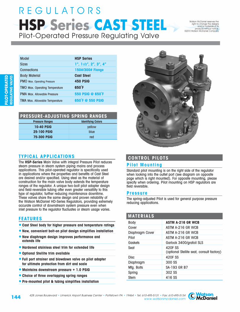
HSP Series CAST STEELR E G U L A T O R S
Pilot-Operated Pressure Regulating Valve
TYPICAL APPLICATIONSThe HSP-Series Main Valve with integral Pressure Pilot reducessteam pressure in steam system piping mains and processapplications. This pilot-operated regulator is specifically used in applications where the properties and benefits of Cast Steelare desired and/or specified. Using steel as the material ofconstruction for the main valve body extends the temperatureranges of the regulator. A unique two-bolt pilot adapter designand field-reversible tubing offer even greater versatility to thistype of regulator, further reducing maintenance downtime. These valves share the same design and proven reliability of the Watson McDaniel HD-Series Regulators, providing extremelyaccurate control of downstream system pressure even when inlet pressure to the regulator fluctuates or steam usage varies.
FEATURES• Cast Steel body for higher pressure and temperature ratings
• New, convenient bolt-on pilot design simplifies installation
• New diaphragm design improves performance andextends life
• Hardened stainless steel trim for extended life
• Optional Stellite trim available
• Full port strainer and blowdown valve on pilot adapter for ultimate protection from dirt and scale
• Maintains downstream pressure + 1.0 PSIG
• Choice of three overlapping spring ranges
• Pre-mounted pilot & tubing simplifies installation
LOTS
Model HSP SeriesSizes 1”, 11/2”, 2”, 3”, 4”Connections 150#/300# FlangeBody Material Cast SteelPMO Max. Operating Pressure 450 PSIG
TMO Max. Operating Temperature 650˚F
PMA Max. Allowable Pressure 550 PSIG @ 650˚F
TMA Max. Allowable Temperature 650˚F @ 550 PSIG
CONTROL PILOTSPi lo t Mount ingStandard pilot mounting is on the right side of the regulatorwhen looking into the outlet port (see diagram on opposite page which is right mounted). For opposite mounting, pleasespecify when ordering. Pilot mounting on HSP regulators are field reversible.
PressureThe spring-adjusted Pilot is used for general purpose pressurereducing applications.
MATERIALSBody ASTM A-216 GR WCBCover ASTM A-216 GR WCBDiaphragm Cover ASTM A-216 GR WCBPilot ASTM A-216 GR WCBGaskets Garlock 3400/grafoil SLSSeat 420F SS
(optional Stellite seat, consult factory)Disc 420F SSDiaphragm 300 SSMfg. Bolts SA-193 GR B7Spring 302 SSStem 416 SS
Watson McDaniel reserves theright to change the designs
and/or materials of itsproducts without notice.
©2010 Watson McDaniel Company
PRESSURE-ADJUSTING SPRING RANGES Pressure Ranges Identifying Colors
10-40 PSIG yellow25-100 PSIG blue75-300 PSIG red
PILO
T-O
PERA
TED
REG
ULAT
ING
VAL
VES
145428 Jones Boulevard • Limerick Airport Business Center • Pottstown PA • 19464 • Tel: 610-495-5131 • Fax: 610-495-5134www.watsonmcdaniel.com
HSP Series CAST STEELR E G U L A T O R S
Pilot-Operated Pressure Regulating Valve
HOW TO ORDERREGULATOR BODYSpecify: • HSP regulator body
• Regulator size or capacity of steam required• End connections (150#/300# flanged)
PILOT REQUIRED TO OPERATE THIS VALVE• Pressure Pilot (Specify Range)
Specify: 10-40 PSIG - Yellow25-100 PSIG - Blue75-300 PSIG - Red
Example: 2” HSP, 150# FLG, 10-40 PSIG (yellow)
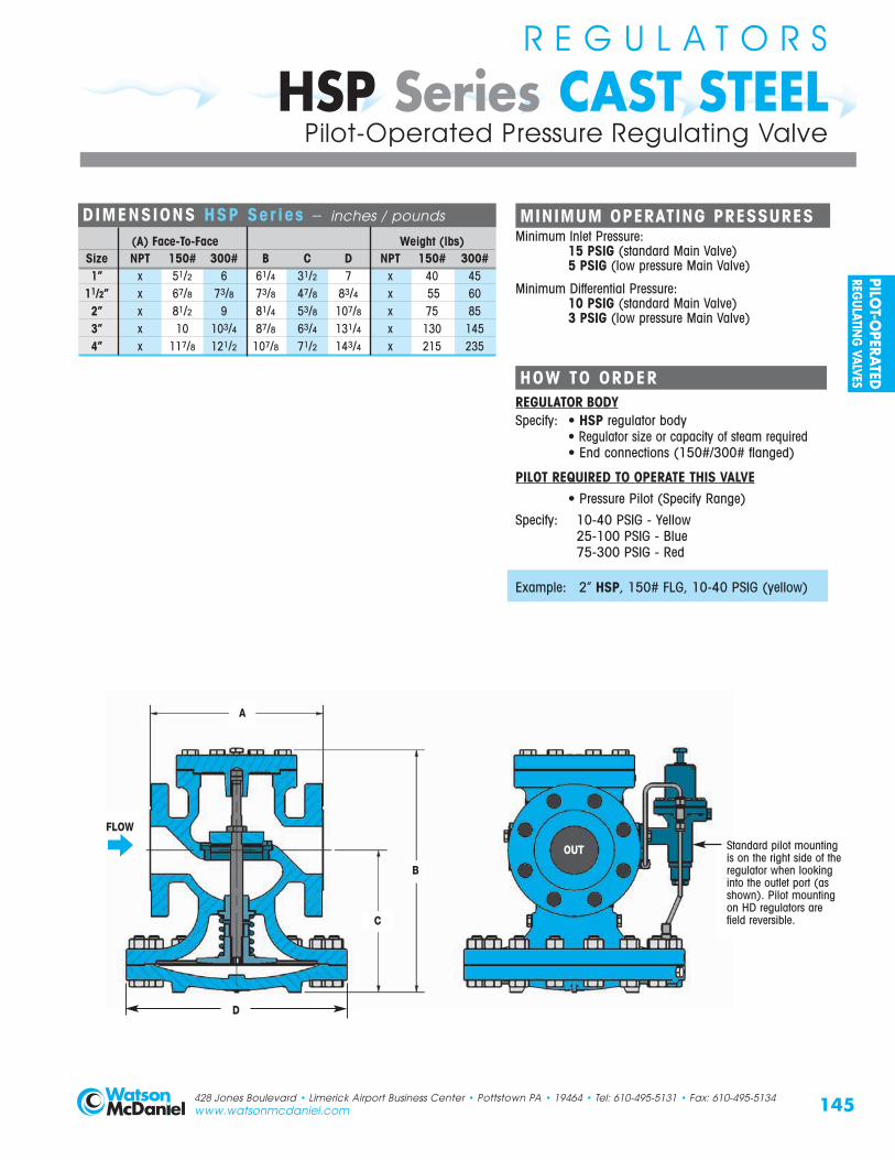
DIMENSIONS HSP Ser ies – inches / pounds
(A) Face-To-Face Weight (lbs)Size NPT 150# 300# B C D NPT 150# 300#1” x 51/2 6 61/4 31/2 7 x 40 45
11/2” x 67/8 73/8 73/8 47/8 83/4 x 55 602” x 81/2 9 81/4 53/8 107/8 x 75 853” x 10 103/4 87/8 63/4 131/4 x 130 1454” x 117/8 121/2 107/8 71/2 143/4 x 215 235
MINIMUM OPERATING PRESSURESMinimum Inlet Pressure:
15 PSIG (standard Main Valve)5 PSIG (low pressure Main Valve)
Minimum Differential Pressure:10 PSIG (standard Main Valve)3 PSIG (low pressure Main Valve)
A
C
B
FLOW
Standard pilot mounting is on the right side of theregulator when looking into the outlet port (asshown). Pilot mounting on HD regulators are field reversible.
OUT
D
PILOT-O
PERATEDREG
ULATING
VALVES

Watson McDaniel reserves theright to change the designs
and/or materials of itsproducts without notice.
©2002 Watson McDaniel Company
NOISE ATTENUATORS
Series-Afor Pressure Regulating Valves
Noise Attenuation Equipment is used to reduce unwanted or excessive noise that commonly occurs in pressure reducing stations.
Series-A DIMENSION (A) – inchesPipe Size 125# Flange 250# Flange
2” 6 43/16
21/2” 7 415/16
3” 71/2 511/16
4” 9 615/16
6” 11 911/16
Note: Other sizes available. Consult factory.
Series A Dimensions
SERIES-AORIFICEPLATE
PressureReducing
Valve
Sensing LineFor Regulator
Series-A Typical Hook-up
Series-A ORIFICE PLATENoise Reduction Capability: 5-10 dBA
HOW IT WORKSThe Series-A Orifice Plate with its drilled orifice pattern isinstalled after the pressure regulating valve to smooth outturbulence caused by the pressure drop across the regulator.Noise reduction levels of 5-10 dBA can typically be achieved.
INSTALLATIONThe Series-A Orifice Plate is installed between ANSI flangesimmediately after the regulator. If the regulator is a flanged unit,the orifice plate is placed at the flange outlet connection.
Series-AOrifice Plate
146
FLOW
A DIa.
.75
Orifice Plate installedbetween flanges
428 Jones Boulevard • Limerick Airport Business Center • Pottstown PA • 19464 • Tel: 610-495-5131 • Fax: 610-495-5134www.watsonmcdaniel.com
Watson McDaniel reserves theright to change the designs
and/or materials of itsproducts without notice.
©2010 Watson McDaniel CompanyORIFICE PLATE
FLOW
PILO
T-O
PERA
TED
REG
ULAT
ING
VAL
VES

HOW IT WORKSThe Series-H Acoustic Silencer incorporates a Dual Diffusertube design. The inner tube has a drilled orifice pattern andthe outer tube contains an integral layer of sound absorbinginsulation. Noise reduction levels of 20-30 dBA can typicallybe achieved.
INSTALLATIONThe Series-H Diffuser Tube should be installed immediatelydownstream of the regulator, as shown below.
Series-HAcoustic Silencer
Series-H ACOUSTIC SILENCER
NOISE ATTENUATORS
Series-Hfor Pressure Regulating Valves
Noise Reduction Capability: 20-30 dBA
Series-H Typical Hook-up
Separator
PRV
SERIES-HACOUSTICSILENCER
PressureSensing Line
Series-H Dimensions
Series-H DIMENSIONS – inches
Model A1 A B C Weight(lbs)
LCV-8 4 8 14 57 145LCV-10 6 10 16 71 210LCV-12 6 12 18 81 295
Note: Other sizes available. Consult factory.
Noise Attenuation Equipment is used to reduce unwanted or excessive noise that commonly occurs in pressure reducing stations.
147
C
BA1 A
Inlet
428 Jones Boulevard • Limerick Airport Business Center • Pottstown PA • 19464 • Tel: 610-495-5131 • Fax: 610-495-5134www.watsonmcdaniel.com
GateValve
GateValve
Strainer
To Trap
ACOUSTIC SILENCER
FLOW
PILOT-O
PERATEDREG
ULATING
VALVES

NOISE ATTENUATORS
Series-Sfor Pressure Regulating Valves
Model Selec t ion Char t fo r Ser ies-S Di f fuser Valve Inlet Pressure
(PSIG)
15 20 25 30 40 50 60 75 90 100 125 150 175 200 225 2501000 S-3 S-3 S-3 S-3 S-3 S-3 S-3 S-3 S-3 S-3 S-3 S-3 S-3 S-3 S-3 S-31500 S-3 S-3 S-3 S-3 S-3 S-3 S-3 S-3 S-3 S-3 S-3 S-3 S-3 S-3 S-3 S-32000 S-4 S-4 S-4 S-4 S-4 S-4 S-4 S-4 S-4 S-4 S-4 S-4 S-4 S-4 S-4 S-43000 S-4 S-4 S-4 S-4 S-4 S-5 S-5 S-5 S-5 S-5 S-5 S-5 S-5 S-5 S-5 S-5 4000 S-5 S-5 S-5 S-5 S-5 S-5 S-5 S-5 S-5 S-5 S-5 S-5 S-5 S-5 S-5 S-5 6000 S-6 S-6 S-6 S-6 S-6 S-6 S-6 S-6 S-6 S-6 S-6 S-6 S-6 S-6 S-6 S-6 8000 S-8 S-8 S-8 S-8 S-8 S-8 S-8 S-8 S-8 S-8 S-8 S-8 S-8 S-8 S-8 S-810000 S-8 S-8 S-8 S-8 S-8 S-8 S-8 S-8 S-8 S-8 S-8 S-8 S-8 S-8 S-8 S-8
Note: For higher capacity models, S-10 & S-12, consult factory.
SteamCapacity(lbs/hr)
Series-SAcoustic Diffuser
Series-S ACOUSTIC DIFFUSER
HOW IT WORKSThe Series-S Acoustic Diffuser incorporates a single tube with a drilled orifice pattern which reduces downstream turbulence.Noise reduction levels of 10-15 dBA can typically be achieved.
INSTALLATIONThe Series-S Diffuser Tube should be installed immediatelydownstream of the regulator, as shown below.
Noise Reduction Capability: 10-15 dBA
Series-S Typical Hook-up
148 428 Jones Boulevard • Limerick Airport Business Center • Pottstown PA • 19464 • Tel: 610-495-5131 • Fax: 610-495-5134www.watsonmcdaniel.com
Separator
PRV
SERIES-SACOUSTICDIFFUSER
PressureSensing Line
GateValve
GateValve
Strainer
To Trap
Watson McDaniel reserves theright to change the designs
and/or materials of itsproducts without notice.
©2010 Watson McDaniel Company
ACOUSTIC DIFFUSER
FLOW
PILO
T-O
PERA
TED
REG
ULAT
ING
VAL
VES

NOISE ATTENUATORS
Series-Sfor Pressure Regulating Valves
Ser ies-S Dimensions – inchesInlet (A) Outlet NPT x Weld Dimensions
NPT FLG FLG/BW B C D
S-33/4 2 51/2 131/2 23/81 2 51/2 131/2 23/8
3/4 4 61/2 131/2 41/21 4 61/2 131/2 41/2
S-4 11/4 4 61/2 131/2 41/211/2 4 61/2 131/2 41/2
2 4 61/2 131/2 41/23/4 4 61/2 161/2 41/21 4 61/2 161/2 41/2
S-5 11/4 4 61/2 161/2 41/211/2 4 61/2 161/2 41/2
2 4 61/2 161/2 41/221/2 21/2 4 61/2 161/2 41/211/4 6 8 14 55/811/2 6 8 14 55/8
S-6 2 6 8 14 55/821/2 21/2 6 8 14 55/8
3 3 6 8 14 55/811/2 8 10 17 85/8
2 8 10 17 85/8S-8 21/2 21/2 8 10 17 85/8
3 3 8 10 17 85/84 4 8 10 17 85/82 12 12 14 123/4
21/2 21/2 12 12 14 123/4S-10 3 3 12 12 14 123/4
4 4 12 12 14 123/46 6 12 12 14 123/4
21/2 21/2 12 12 21 123/4
S-12 3 3 12 12 21 123/44 4 12 12 21 123/46 6 12 12 21 123/4
Notes: 1)150# & 300# flanges available.2) Other sizes available; consult factory.
Model
NPT x Weld
Flanged x Weld
NPT x Flanged
Flanged x Flanged
149
D
BC
ANPT
428 Jones Boulevard • Limerick Airport Business Center • Pottstown PA • 19464 • Tel: 610-495-5131 • Fax: 610-495-5134www.watsonmcdaniel.com
ACOUSTIC DIFFUSER
AFlanged
ANPT
AFlanged
PILOT-O
PERATEDREG
ULATING
VALVES

150
Full Port Regulating Valves – Capacities
InletPressure(PSIG)
OutletPressure(PSIG)
Cv Factors
1/2" 3/4" 1" 11/4" 11/2" 2" 21/2" 3" 4" 6"
3.8 6.7 11 15 21 37 55 71 113 241
CAPACIT IES – Steam (lbs/hr) FULL PORT
HD & HSP SeriesR E G U L A T O R S
5 0 85 150 250 350 500 800 1200 1600 2600 55002 80 140 230 310 440 770 1100 1500 2400 51000 115 200 325 450 600 1100 1650 2100 3600 7800
7 2 105 180 300 400 575 1000 1500 2000 3100 67003 90 160 275 375 525 900 1300 1800 2800 60000 150 260 425 575 850 1500 2200 2800 4600 9900
10 2 140 240 400 550 800 1400 2100 2700 4300 91005 100 175 300 400 600 1000 1600 2000 3200 69000 160 280 475 600 900 1600 2400 3100 4900 10300
12 4 140 240 400 550 800 1400 2100 2700 4300 91007 125 200 375 500 700 1200 1900 2400 3800 8200
0-3 190 325 550 750 1000 1800 2700 3500 5600 1200015 5 175 300 500 700 900 1700 2500 3200 5200 11100
8 140 250 400 500 800 1300 2000 2600 4200 89000-5 210 375 625 850 1200 2100 3100 4000 6400 13700
20 10 190 325 550 750 1000 1800 2700 3500 5600 1200012 170 300 500 675 950 1600 2500 3200 5100 10800
0-7 250 450 775 1050 1500 2600 3800 5000 7900 1690025 10 225 425 700 975 1300 2400 3600 4600 7300 15600
15 200 350 600 800 1100 2000 3000 3900 6200 132000-12 275 500 800 1100 1500 2700 4100 5200 8300 17800
30 15 250 450 750 1000 1400 2500 3800 4900 7800 1660020 225 375 650 850 1200 2100 3200 4100 6500 14000
0-18 350 600 1000 1350 1900 3300 5000 6400 10300 2190040 25 300 500 850 1150 1600 2800 4200 5400 8700 18500
30 250 425 700 1000 1400 2500 3700 4700 7600 161000-20 400 700 1200 1650 2300 4100 6000 7800 12400 26500
50 30 350 650 1100 1500 2000 3600 5400 6900 11000 2360040 275 500 800 1100 1500 2700 4100 5200 8300 17800
0-30 475 850 1350 1900 2600 4600 6900 8900 14200 3030060 35 425 775 1250 1700 2400 4300 6400 8200 13100 27900
50 300 525 850 1200 1600 2900 4300 5600 8900 190000-35 575 1000 1650 2300 3200 5600 8300 10800 17200 36600
75 50 475 825 1350 1900 2600 4600 6900 8900 14100 3010060 400 700 1150 1600 2200 3900 5800 7400 11800 25200
0-45 675 1200 1950 2700 3700 6600 9800 12700 20200 4310090 60 575 1000 1700 2300 3200 5700 8500 10900 17400 37100
75 425 750 1200 1700 2300 4100 6100 7900 12600 270000-50 750 1300 2100 3000 4100 7300 10800 14000 22200 47500
100 60 700 1200 2000 2700 3800 6700 10000 12900 20500 4380080 500 875 1400 1900 2700 4800 7100 9200 14700 31300
0-60 925 1650 2700 3700 5200 9100 14000 17500 28000 59500125 75 825 1475 2400 3300 4600 8200 12200 15700 25000 53500
100 625 1100 1800 2500 3500 6200 9200 11900 19000 404000-75 1100 1900 3100 4300 6000 10600 15800 20400 32400 69100
150 100 925 1600 2700 3600 5100 9000 13400 17400 27700 59000125 650 1150 1900 2600 3600 6400 9500 12300 19600 41900
0-85 1275 2250 3700 5000 7100 12500 18600 24000 38200 81400175 125 1000 1800 2900 4000 5600 9900 14700 18900 30100 64300
150 750 1300 2100 2900 4100 7300 10800 14000 22200 475000-100 1450 2500 4200 5700 8000 14100 21000 27100 43100 92000
200 125 1300 2300 3700 5100 7100 12600 18700 24100 38400 81900150 1075 1900 3100 4300 6000 10600 15700 20300 32300 68900
0-120 1575 2800 4600 6200 8700 15400 22900 29500 47000 100200225 150 1450 2500 4200 5700 8000 14100 21000 27200 43300 92300
175 1350 2400 3900 5300 7400 13100 19500 25200 40100 855000-130 1750 3100 5100 6900 9700 17100 25500 32900 53400 111800
250 150 1650 2900 4700 6500 9100 16000 23800 30800 49000 104600200 1200 2100 3500 4800 6700 11900 17600 22800 36200 77300
0-160 2045 3605 5920 8075 11310 19220 29610 38230 60840 129750300 175 1945 3425 5625 7670 10740 18925 28130 36320 57800 123270
200 1780 3140 5155 7030 9840 17340 25780 33275 52960 112950
Note: For inlet pressures in shaded area, use low pressure main valve and low pressure temperature pilot.
Watson McDaniel reserves theright to change the designs
and/or materials of itsproducts without notice.
©2010 Watson McDaniel Company
PILO
T-O
PERA
TED
REG
ULAT
ING
VAL
VES

151Note: For inlet pressures in shaded area, use low pressure main valve and low pressure temperature pilot.
InletPressure(PSIG)
OutletPressure(PSIG)
Cv Factors
1/2" 3/4" 1" 11/4" 11/2" 2" 21/2" 3" 4" 6"
1.4 3.3 5.6 7.8 13.3 18.8 25.9 41.7 74 163
CAPACIT IES – Steam (lbs/hr) REDUCED PORT
HD & HSP SeriesR E G U L A T O R S
Reduced Port Regulating Valves – Capacities
5 0 15 35 59 82 140 197 272 438 777 17122 13 32 53 75 128 181 249 401 712 15690 21 48 82 115 195 276 381 613 1088 2396
7 2 20 46 79 110 187 265 365 587 1042 22963 19 44 74 104 177 250 344 554 983 21650 29 70 117 164 279 395 544 876 1554 3423
10 2 28 68 115 160 274 387 533 858 1523 33545 25 60 102 142 242 342 471 758 1346 29640 35 83 141 197 335 473 653 1051 1865 4108
12 4 33 78 133 185 316 446 615 990 1758 38737 29 68 115 160 272 385 530 854 1515 3336
0-3 43 102 173 241 410 580 800 1287 2284 503115 5 41 98 166 232 395 558 769 1238 2198 4841
8 37 88 149 208 354 500 690 1111 1972 43430-5 57 134 227 317 541 764 1053 1696 3009 6629
20 10 51 120 204 284 483 684 942 1517 2692 592912 47 111 188 262 447 632 870 1401 2486 5477
0-7 70 166 282 393 670 948 1305 2102 3730 821525 10 67 158 269 375 640 905 1246 2006 3561 7843
15 59 139 235 328 559 790 1088 1751 3108 68460-12 81 190 323 450 768 1085 1495 2408 4273 9411
30 15 76 180 305 426 726 1025 1413 2275 4037 889220 66 155 263 366 625 883 1216 1958 3475 7654
0-18 105 248 420 585 998 1410 1943 3128 5551 1222740 25 99 199 367 511 872 1232 1698 2734 4852 10688
30 78 183 311 433 739 1044 1439 2317 4111 90560-20 135 318 539 751 1280 1809 2492 4013 7121 15686
50 30 118 277 470 655 1117 1579 2175 3502 6216 1369240 88 208 353 491 838 1184 1632 2627 4662 10269
0-30 153 360 611 851 1451 2051 2826 4550 8074 1778660 35 143 338 573 798 1361 1924 2651 4268 7573 16682
50 98 230 390 543 926 1309 1804 2904 5154 113530-35 195 460 780 1086 1853 2619 3608 5809 10308 22706
75 50 164 387 657 916 1561 2207 3040 4895 8687 1913560 132 312 529 737 1257 1777 2448 3941 6993 15404
0-45 229 540 916 1277 2177 3077 4239 6825 12112 2668090 60 197 465 789 1100 1874 2648 3649 5874 10425 22962
75 146 345 585 815 1389 1964 2705 4357 7731 170290-50 255 600 1018 1419 2419 3419 4710 7584 13458 29644
100 60 235 554 940 1310 2234 3158 4351 7006 12432 2738480 176 416 706 983 1676 2367 3263 5254 9324 20538
0-60 322 760 1290 1796 3063 4329 5964 9603 17041 37536125 75 294 693 1176 1638 2793 3948 5439 8757 15540 34230
100 221 518 882 1229 2095 2961 4079 6568 11655 256720-75 381 900 1527 2128 3628 5128 7065 11376 20187 44467
150 100 329 775 1315 1831 3123 4414 6081 9791 17374 38270125 243 575 975 1385 2316 3274 4510 7261 12885 28382
0-85 449 1060 1800 2505 4272 6939 8320 13396 23771 52362175 125 360 849 1440 2006 3421 4835 6661 10725 19032 41923
150 265 625 1060 1476 2518 3558 5606 7893 14008 308550-100 509 1200 2037 2837 4838 6838 9420 15168 26916 59288
200 125 459 1082 1836 2557 4360 6164 8492 13672 24262 53442150 389 917 1556 2167 3695 5223 7195 11584 20557 45232
0-120 560 1319 2238 3117 5360 7514 10351 16667 29577 65150225 150 493 1162 1972 2747 4684 6621 9121 14686 26061 57405
175 416 980 1663 2316 3950 5583 7692 12384 21976 484090-130 628 1480 2511 3498 5964 8431 11614 18700 33184 73095
250 150 588 1386 2352 3276 5586 7896 10878 17514 31080 68460200 441 1040 1764 2457 4190 5922 8159 13136 23310 51345
0-160 755 1775 3015 4200 7160 10120 13945 22450 39840 87760300 175 715 1690 2865 3990 6800 9615 13250 21330 37850 83370
200 655 1550 2625 3655 6235 8810 12140 19545 34680 76400
PILOT-O
PERATEDREG
ULATING
VALVES