11.control box installation - ducatihome.cloud · ducati kontrol “small” control box ducati...
TRANSCRIPT
33
120 mm180 mm
290 mm
120 mm
120 mm
290 mm
D U C A T I K o n t r o l “ s m a l l ”Control Box
D U C A T I K o n t r o l “ l a r g e ”Control Box
B
A
AB
39 40
DUCATI Control box10. PREDISPOSITIONS
Prepare the insulated cable ducts for motors and accessories wires (not supplied). Prepare the power plant to the location where you intend to attach the control unit (not necessary in the case of self-powered SOLAR PANEL powered openers) Warning: the power of the high-voltage current must be managed exclusively by a specialized technician. Do not manage yourself the power supply connection 230 / 110V: Danger of Death!
Caution: it is recommended to prepare a disconnection device to be used in case of emergency. Warning: the control unit and activation commands must be installed in a not acessible place and at a height from the ground, not allowing the use by unauthorized persons or children.
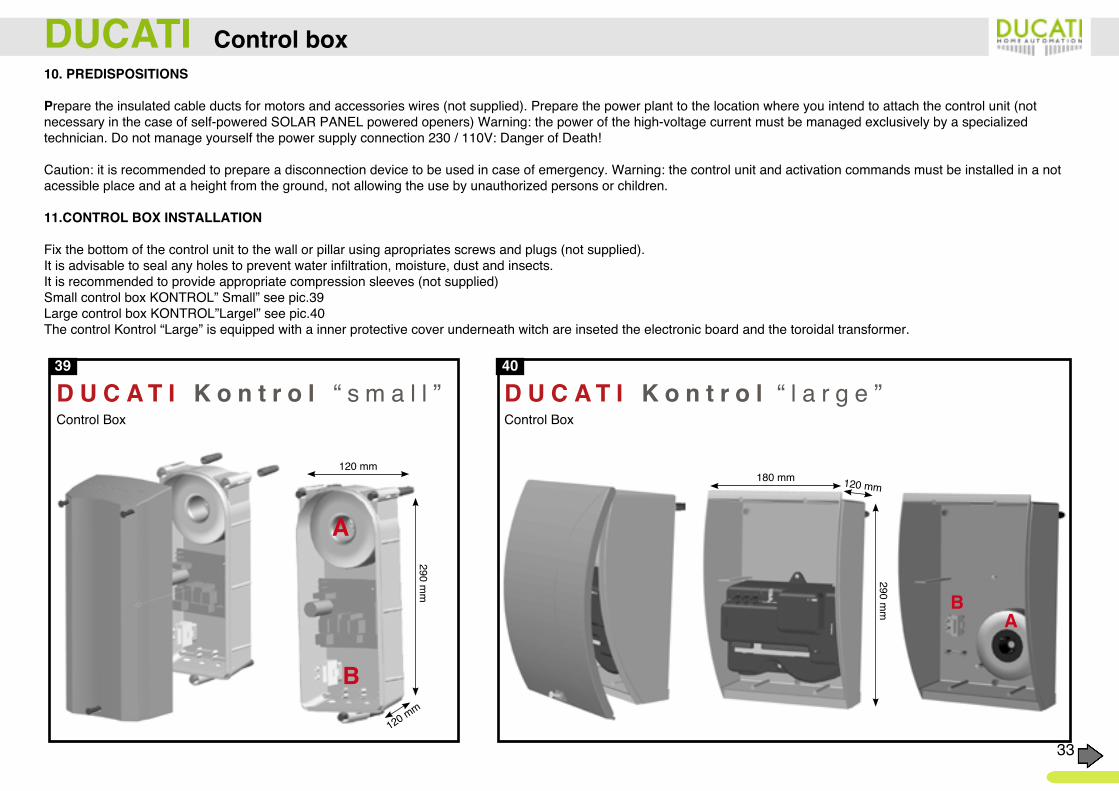
11.CONTROL BOX INSTALLATION
Fix the bottom of the control unit to the wall or pillar using apropriates screws and plugs (not supplied). It is advisable to seal any holes to prevent water infiltration, moisture, dust and insects. It is recommended to provide appropriate compression sleeves (not supplied)Small control box KONTROL” Small” see pic.39 Large control box KONTROL”Largel” see pic.40 The control Kontrol “Large” is equipped with a inner protective cover underneath witch are inseted the electronic board and the toroidal transformer.
DUCATI DUCATI How to install the actuator
34
A . C .
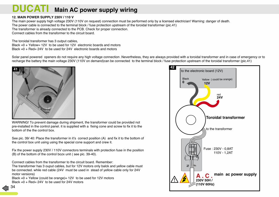
Fuse : 230V - 0,8AT 110V - 1,2AT
to the transformer
to the electronic board (12V)
N
NF
0 12V
24V
230V 50H /(110V 60Hz)
Black Yellow ( could be orange)
red
WARNING! To prevent damage during shipment, the transformer could be provided not pre-installed in the control panel. it is supplied with a fixing cone and screw to fix it to the bottom of the the control box.
See pic. 39/ 40: Place the transformer in it’s correct position (A) and fix it to the bottom of the control box unit using using the special cone support and crew it.
Fix the power supply 230V / 110V connectors terminals with protection fuse in the position (B) of the bottom of the control bozx unit ( see pic. 39-40).
Connect cables from the transformer to the circuit board. Remember:The transformer has 3 ouput cables, but for 12V motors only balck and yellow cable must be connected. while red cable (24V must be used in stead of yellow cable only for 24V motor versions)Black =0 + Yellow (could be orange)= 12V to be used for 12V motorsBlack =0 + Red= 24V to be used for 24V motors
Toroidal transformer
12. MAIN POWER SUPPLY 230V / 110 VThe main power supply high voltage 230V (110V on request) connection must be performed only by a licensed electrician! Warning: danger of death.The power cable is connected to the terminal block / fuse protection upstream of the toroidal transformer (pic.41)The transformer is already connected to the PCB. Check for proper connection.Connect cables from the transformer to the circuit board.
The toroidal transformer has 3 output cables, Black =0 + Yellow= 12V to be used for 12V electronic boards and motorsBlack =0 + Red= 24V to be used for 24V electronic boards and motors
Solar panel powered openers do not require any high voltage connection .Nevertheless, they are always provided with a toroidal transformer and in case of emergency or to recharge the battery the main voltage 230V (110V on demand)can be connected to the terminal block / fuse protection upstream of the toroidal transformer (pic.41)
41 42
DUCATI Main AC power supply wiring
main ac power supply
48
DUCATI Electronic control board model CTH48 (& CTH48/24V)
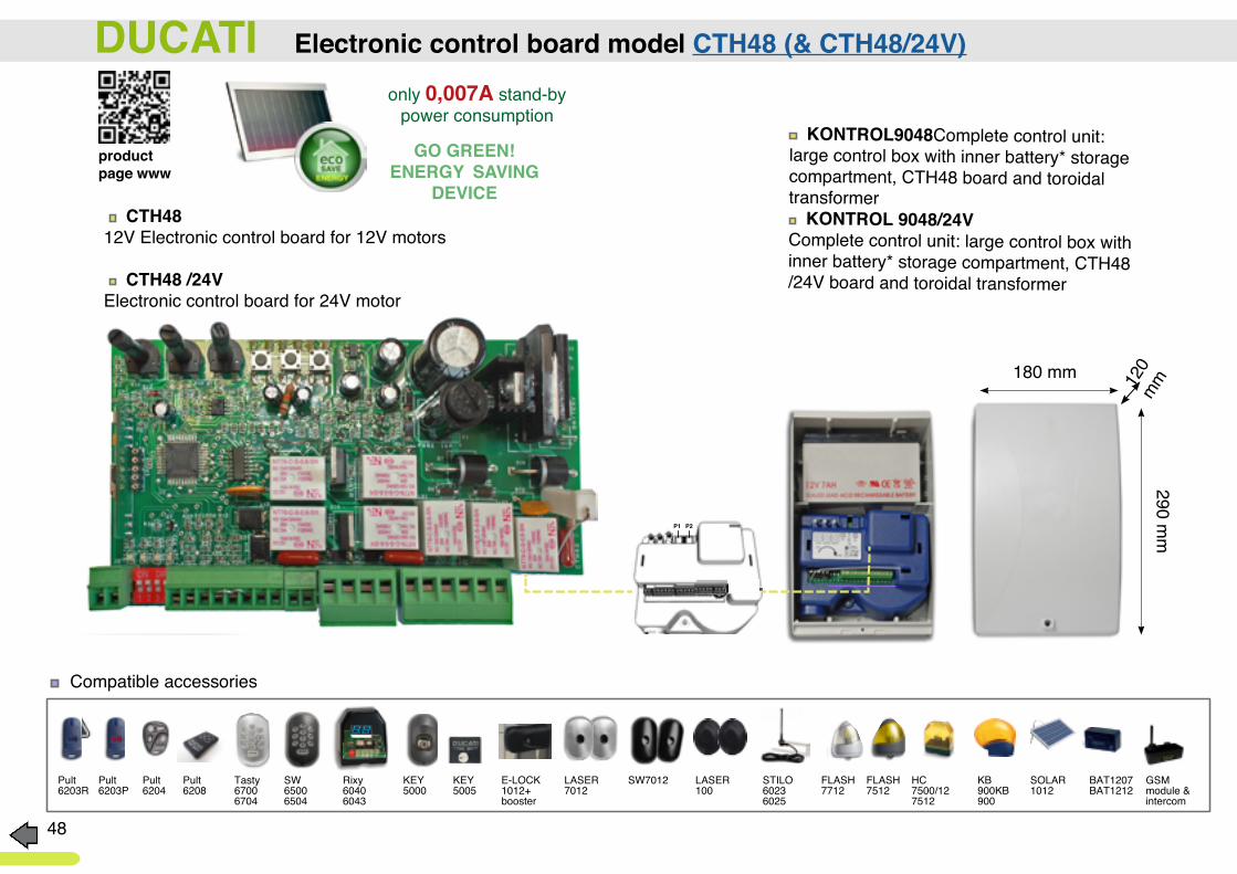
KONTROL9048Complete control unit: large control box with inner battery* storage compartment, CTH48 board and toroidal transformer KONTROL 9048/24V
Complete control unit: large control box with inner battery* storage compartment, CTH48 /24V board and toroidal transformer
CTH48 12V Electronic control board for 12V motors
CTH48 /24VElectronic control board for 24V motor
120
mm180 mm
290 mmP1 P2
Pult 6203R
Tasty67006704
Pult 6204
Rixy 60406043
Pult 6203P
SW65006504
Pult 6208
KEY5000
KEY5005
E-LOCK 1012+ booster
LASER 7012
LASER 100
STILO60236025
FLASH7712
FLASH7512
SOLAR 1012
HC7500/127512
BAT1207BAT1212
KB900KB900
SW7012
Compatible accessories
GSM module &intercom
only 0,007A stand-by power consumption
GO GREEN! ENERGY SAVING
DEVICE
product page www
49
DUCATI Electronic control board model CTH48 (& CTH48/24V)
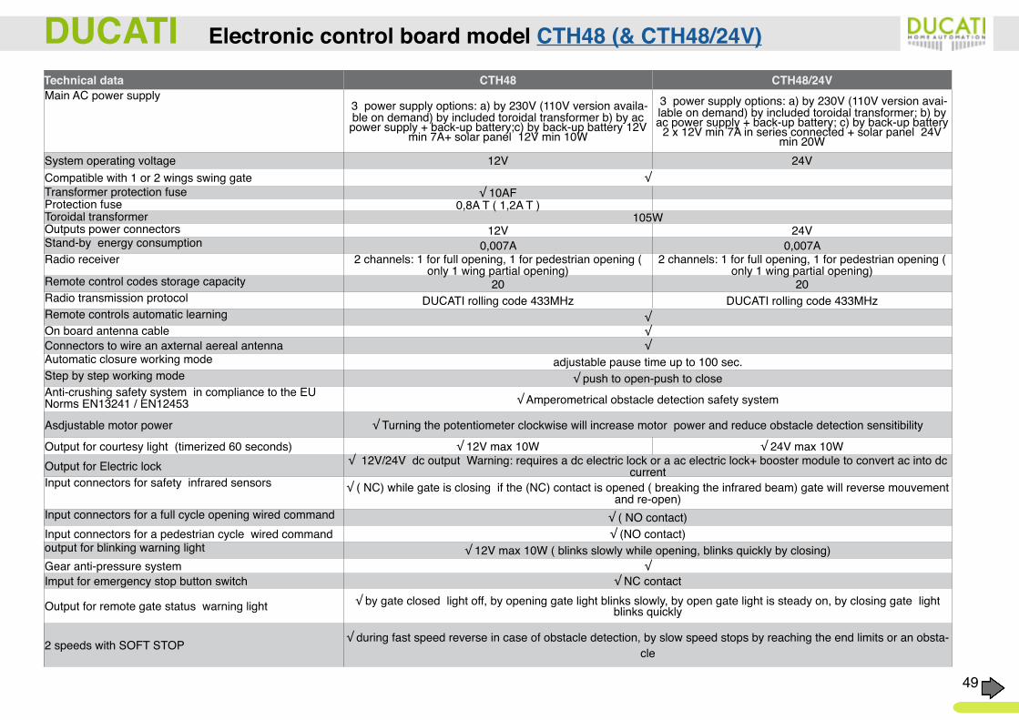
Technical data CTH48 CTH48/24VMain AC power supply
3 power supply options: a) by 230V (110V version availa-ble on demand) by included toroidal transformer b) by ac power supply + back-up battery;c) by back-up battery 12V
min 7A+ solar panel 12V min 10W
3 power supply options: a) by 230V (110V version avai-lable on demand) by included toroidal transformer; b) by ac power supply + back-up battery; c) by back-up battery
2 x 12V min 7A in series connected + solar panel 24V min 20W
System operating voltage 12V 24VCompatible with 1 or 2 wings swing gate √Transformer protection fuse √ 10AFProtection fuse 0,8A T ( 1,2A T )Toroidal transformer 105WOutputs power connectors 12V 24VStand-by energy consumption 0,007A 0,007ARadio receiver 2 channels: 1 for full opening, 1 for pedestrian opening (
only 1 wing partial opening)2 channels: 1 for full opening, 1 for pedestrian opening (
only 1 wing partial opening)Remote control codes storage capacity 20 20Radio transmission protocol DUCATI rolling code 433MHz DUCATI rolling code 433MHzRemote controls automatic learning √On board antenna cable √Connectors to wire an axternal aereal antenna √Automatic closure working mode adjustable pause time up to 100 sec.Step by step working mode √ push to open-push to closeAnti-crushing safety system in compliance to the EU Norms EN13241 / EN12453 √ Amperometrical obstacle detection safety system
Asdjustable motor power √ Turning the potentiometer clockwise will increase motor power and reduce obstacle detection sensitibility
Output for courtesy light (timerized 60 seconds) √ 12V max 10W √ 24V max 10WOutput for Electric lock √ 12V/24V dc output Warning: requires a dc electric lock or a ac electric lock+ booster module to convert ac into dc
current Input connectors for safety infrared sensors √ ( NC) while gate is closing if the (NC) contact is opened ( breaking the infrared beam) gate will reverse mouvement
and re-open)Input connectors for a full cycle opening wired command √ ( NO contact)Input connectors for a pedestrian cycle wired command √ (NO contact)output for blinking warning light √ 12V max 10W ( blinks slowly while opening, blinks quickly by closing)Gear anti-pressure system √Imput for emergency stop button switch √ NC contact
Output for remote gate status warning light √ by gate closed light off, by opening gate light blinks slowly, by open gate light is steady on, by closing gate light blinks quickly
2 speeds with SOFT STOP √ during fast speed reverse in case of obstacle detection, by slow speed stops by reaching the end limits or an obsta-cle
50
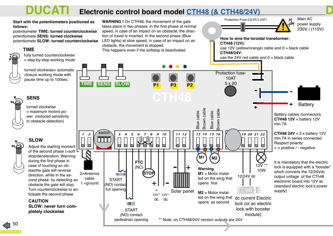
fully turned counterclockwise = step-by-step working mode
turned clockwise= automatic closure working mode with pause time up to 100sec.
dc current Electric lock (or ac electric lock with booster
module)
-Battery
-FUSE
FTC(NC)
CTH48
12V ** 10W
M1 M2
STOP-
-+
+
Protection fuse-10AT5 x 20
Protection Fuse 0,8 AT(1,2AT)
CAUTIONSLOW: never turn com-pletely clockwise
TIME SENS SLOW
START(NO) contact full opening
START(NO) contact
pedestrian opening
It is mandatory that the electric lock is equipped with a “booster” which converts the 12/24Vdc output voltage of the CTh48 electronic board into 12V ac (standard electric lock’s power supply)+
12V** dc
-12V** dc
WarningM1 = Motor instal-led on the wing that opens first
M2 = Motor instal-led on the wing that opens as second
Blue
cab
le
Blue
cab
le
Brow
n ca
ble
Brow
n ca
ble
12/24V dc
P1 P2P3
DUCATI Electronic control board model CTH48 (& CTH48/24V) DUCATI Electronic control board model CTH48 (& CTH48/24V)
turned clockwise= maximum motors po-wer (reduced sensitivityin obstacle detection)
Adjust the starting moment of the second phase (=soft stop/deceleration. Warning: during the first phase in case of touching an ob-stacthe gate will reverse direction, while in the se-cond phese by detecting an obstacle the gate will stop. Turn counterclockwise to an-ticipate the second phase
TIME
SENS
SLOW
WARNING ! On CTH48, the movement of the gate takes place in two phases: in the first phase at normal speed, in case of an impact on an obstacle, the direc-tion of travel is inverted. In the second phase (Blue LED lights) at slow speed, in case of an impact on an obstacle, the movement is stopped.This happens even if the softstop is deactivated
Start with the potentiometers positioned as follows:potentiometer TIME: turned counterclockwisepotentiomete SENS: turned clockwisepotentiomete SLOW: turned counterclockwise How to wire the toroidal transformer:
CTH48 (12V):use 12V (yellow/orange) cable and 0 = black cable CTH48/24V:use the 24V red cable and 0 = black cable
Battery cables /connectorsCTH48 12V = battery 12V min.7A
CTH48 24V = 2 x battery 12V min.7A in series connectedRespect polarity: + = positive / - negative
Main ACpower supply230V / (110V)
2=Antenna cable
1 =ground
switch
Solar panel
** Note: on CTH48/24V version outputs are 24V

51
SWITCH N° 1 in ON (upper position) = use on 2 wings gate
DUCATI Electronic control board model CTH48 (& CTH48/24V) DUCATI Electronic control board model CTH48 (& CTH48/24V)switch
Main ACpower supply230V / (110V)
SWITCH 4 in ON (upper position): active courtesy light / garden light lighting time 20sec. you have 2 options of use:A1) NO dry contact becomes NC to activate a small 12V bulb max.10W B1) a relay for any lighting system of higher power. 12V 10W max output terminals 17-18
OFFSTATUS
GARDENLIGHT
ON B1) Garden Light powered by 220/110V /110V
B2 ) ONLY 3 wires to get remote gate status signal and a wired command to keep the gate open
AC
RELAYK
A1) courtesy light 12V max 10W
A2) remote gate status signal
remote gate status signal
12V max 10W lamp
switch T1
Keep the gate open
remote gate status signal
12V max 10W lamp
START
ON
SWITCH N° 2 in OFF (lower position) = Activate the SOFT STOP function Note: the soft stop (deceleration) beginning point can be adjusted: by turning the trimmer T3, clockwise it delays the beginning of the deceleration.Warning: in the first phase (at standard speed) in case of obstacle detection the direction is inverted, while during the second phase (blue LED lights) in case of obstacle detection, the movement is stopped ( the gate will stop reaching the mechanical end limit).
SWITCH N° 2 in ON (upper position) = soft stop will be deactivated and the gate will work only at 1 speed
SWITCH 3 in ON (upper position) only if coombined with automatic closure (potentiometer T1 must have been turned clockwise to activate the automatic closure function) will enable:- any impulse/ command (by remote control or wired keyswitch) during the automatic closing operation, will stop and re-open of the gate - any impulse/ command (by remote control or wired keyswitch) during the timerized pause time (while gate is open), will increase the dwell time for a time equivalent to that programmed.- maintaining closed the“START” NO contact (for example by connecting a braker), the gate will stay open any commandSWITCH 3 in OFF (lower position), only if coombined with automatic closure (potentiometer T1 must have been turned clockwise to activate the automatic closure function) will enable activates the SEMI-AUTOMATIC MODE (or also called ANTI-THIEF MODE)The opener will accepts impulses (by remote control or wired keyswitch)during the dwell pause phase,anticipating the closure of the gate. during closure manoeuver an impulse will produces the sequence: STOP-REVERSE OPERATION
FASTON
OFF
ON
OFF
KEEPOPEN
SEMI-AUTOMA-TIC
OFF SWITCH N° 1 in OFF (lower position) = use on 1 wing gate
SWITCH 4 in OFF (lower position) ***activate the remote indication of the gate status . A2) by wiring a LED lamp for example, you can remotely monitor the gate status: open = light on, slow flashing = opening, quick flashing = closing; off = gate closed.Output 12V max 10W lamp to be connected to terminals 17 -18
B2) to get the remote gate status signal and an aditional command to keep the gate open by 3 wires only follow this instructions:( warning: this is possible only with automatic closure mode = potentiometer T1 turned clockwise and switch n° 3 on ON position)1-connect terminal 9 to terminal 172- connect 3 wires to terminals 3-4-183- By closing contact between terminal 3 & 4 you will open the gate ( connect a switch)4- Buy holding the contact between terminals 3 & 4 closed the gate will be kept open (connect a braker)5- *** connecting terminals 4 & 18 to a 12V max 10W lamp you will get the remote indication of the gate status .
52
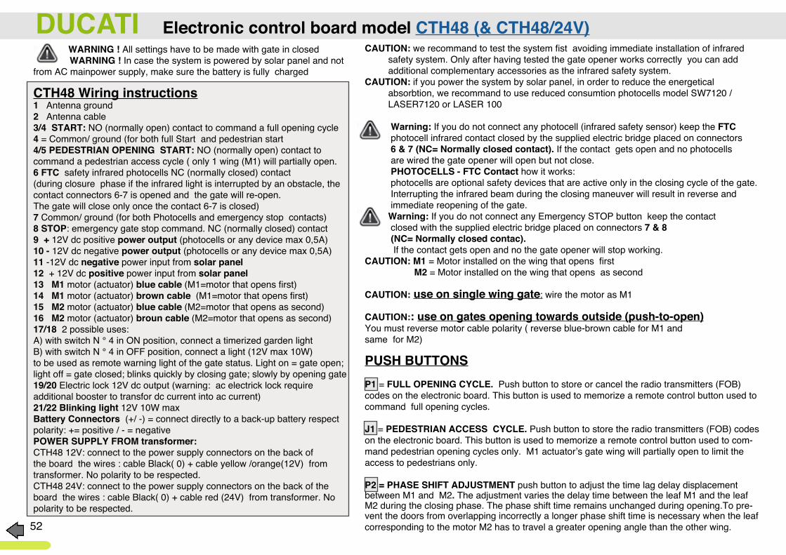
WARNING ! All settings have to be made with gate in closed WARNING ! In case the system is powered by solar panel and not from AC mainpower supply, make sure the battery is fully charged
CTH48 Wiring instructions1 Antenna ground2 Antenna cable3/4 START: NO (normally open) contact to command a full opening cycle4 = Common/ ground (for both full Start and pedestrian start4/5 PEDESTRIAN OPENING START: NO (normally open) contact to command a pedestrian access cycle ( only 1 wing (M1) will partially open.6 FTC safety infrared photocells NC (normally closed) contact (during closure phase if the infrared light is interrupted by an obstacle, the contact connectors 6-7 is opened and the gate will re-open. The gate will close only once the contact 6-7 is closed) 7 Common/ ground (for both Photocells and emergency stop contacts)8 STOP: emergency gate stop command. NC (normally closed) contact9 + 12V dc positive power output (photocells or any device max 0,5A)10 - 12V dc negative power output (photocells or any device max 0,5A)11 -12V dc negative power input from solar panel12 + 12V dc positive power input from solar panel13 M1 motor (actuator) blue cable (M1=motor that opens first)14 M1 motor (actuator) brown cable (M1=motor that opens first)15 M2 motor (actuator) blue cable (M2=motor that opens as second)16 M2 motor (actuator) broun cable (M2=motor that opens as second)17/18 2 possible uses:A) with switch N ° 4 in ON position, connect a timerized garden lightB) with switch N ° 4 in OFF position, connect a light (12V max 10W) to be used as remote warning light of the gate status. Light on = gate open; light off = gate closed; blinks quickly by closing gate; slowly by opening gate19/20 Electric lock 12V dc output (warning: ac electrick lock require additional booster to transfor dc current into ac current)21/22 Blinking light 12V 10W maxBattery Connectors (+/ -) = connect directly to a back-up battery respect polarity: += positive / - = negative POWER SUPPLY FROM transformer:CTH48 12V: connect to the power supply connectors on the back of the board the wires : cable Black( 0) + cable yellow /orange(12V) from transformer. No polarity to be respected.CTH48 24V: connect to the power supply connectors on the back of the board the wires : cable Black( 0) + cable red (24V) from transformer. No polarity to be respected.
CAUTION: we recommand to test the system fist avoiding immediate installation of infrared safety system. Only after having tested the gate opener works correctly you can add additional complementary accessories as the infrared safety system.CAUTION: if you power the system by solar panel, in order to reduce the energetical absorbtion, we recommand to use reduced consumtion photocells model SW7120 / LASER7120 or LASER 100 Warning: If you do not connect any photocell (infrared safety sensor) keep the FTC photocell infrared contact closed by the supplied electric bridge placed on connectors 6 & 7 (NC= Normally closed contact). If the contact gets open and no photocells are wired the gate opener will open but not close. PHOTOCELLS - FTC Contact how it works: photocells are optional safety devices that are active only in the closing cycle of the gate. Interrupting the infrared beam during the closing maneuver will result in reverse and immediate reopening of the gate. Warning: If you do not connect any Emergency STOP button keep the contact closed with the supplied electric bridge placed on connectors 7 & 8 (NC= Normally closed contac). If the contact gets open and no the gate opener will stop working.CAUTION: M1 = Motor installed on the wing that opens first M2 = Motor installed on the wing that opens as second CAUTION: use on single wing gate: wire the motor as M1
CAUTION:: use on gates opening towards outside (push-to-open)You must reverse motor cable polarity ( reverse blue-brown cable for M1 and same for M2)
PUSH BUTTONSP1 = FULL OPENING CYCLE. Push button to store or cancel the radio transmitters (FOB) codes on the electronic board. This button is used to memorize a remote control button used to command full opening cycles.
J1 = PEDESTRIAN ACCESS CYCLE. Push button to store the radio transmitters (FOB) codes on the electronic board. This button is used to memorize a remote control button used to com-mand pedestrian opening cycles only. M1 actuator’s gate wing will partially open to limit the access to pedestrians only.
P2 = PHASE SHIFT ADJUSTMENT push button to adjust the time lag delay displacement between M1 and M2. The adjustment varies the delay time between the leaf M1 and the leaf M2 during the closing phase. The phase shift time remains unchanged during opening.To pre-vent the doors from overlapping incorrectly a longer phase shift time is necessary when the leaf corresponding to the motor M2 has to travel a greater opening angle than the other wing.
DUCATI Electronic control board model CTH48 (& CTH48/24V)
53
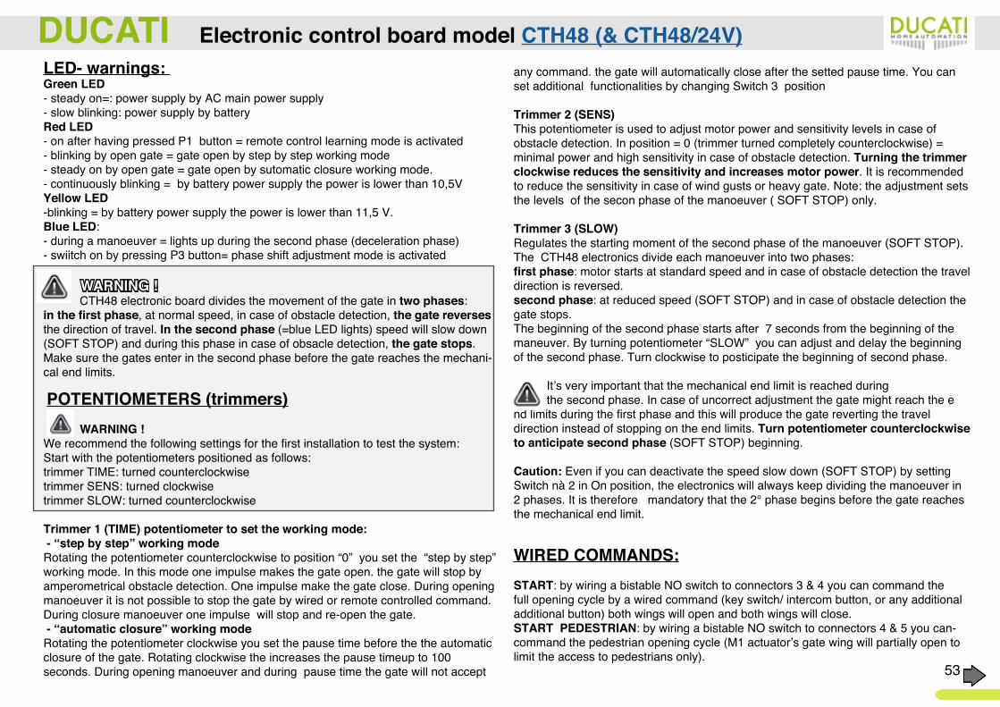
LED- warnings: Green LED - steady on=: power supply by AC main power supply - slow blinking: power supply by batteryRed LED - on after having pressed P1 button = remote control learning mode is activated- blinking by open gate = gate open by step by step working mode- steady on by open gate = gate open by sutomatic closure working mode. - continuously blinking = by battery power supply the power is lower than 10,5V Yellow LED -blinking = by battery power supply the power is lower than 11,5 V.Blue LED: - during a manoeuver = lights up during the second phase (deceleration phase) - swiitch on by pressing P3 button= phase shift adjustment mode is activated
WARNING ! CTH48 electronic board divides the movement of the gate in two phases: in the first phase, at normal speed, in case of obstacle detection, the gate reverses the direction of travel. In the second phase (=blue LED lights) speed will slow down (SOFT STOP) and during this phase in case of obsacle detection, the gate stops. Make sure the gates enter in the second phase before the gate reaches the mechani-cal end limits.
POTENTIOMETERS (trimmers) WARNING ! We recommend the following settings for the first installation to test the system:Start with the potentiometers positioned as follows:trimmer TIME: turned counterclockwisetrimmer SENS: turned clockwisetrimmer SLOW: turned counterclockwise
Trimmer 1 (TIME) potentiometer to set the working mode: - “step by step” working mode Rotating the potentiometer counterclockwise to position “0” you set the “step by step” working mode. In this mode one impulse makes the gate open. the gate will stop by amperometrical obstacle detection. One impulse make the gate close. During opening manoeuver it is not possible to stop the gate by wired or remote controlled command. During closure manoeuver one impulse will stop and re-open the gate. - “automatic closure” working modeRotating the potentiometer clockwise you set the pause time before the the automatic closure of the gate. Rotating clockwise the increases the pause timeup to 100 seconds. During opening manoeuver and during pause time the gate will not accept
any command. the gate will automatically close after the setted pause time. You can set additional functionalities by changing Switch 3 position
Trimmer 2 (SENS) This potentiometer is used to adjust motor power and sensitivity levels in case of obstacle detection. In position = 0 (trimmer turned completely counterclockwise) = minimal power and high sensitivity in case of obstacle detection. Turning the trimmer clockwise reduces the sensitivity and increases motor power. It is recommended to reduce the sensitivity in case of wind gusts or heavy gate. Note: the adjustment sets the levels of the secon phase of the manoeuver ( SOFT STOP) only.
Trimmer 3 (SLOW) Regulates the starting moment of the second phase of the manoeuver (SOFT STOP). The CTH48 electronics divide each manoeuver into two phases: first phase: motor starts at standard speed and in case of obstacle detection the travel direction is reversed.second phase: at reduced speed (SOFT STOP) and in case of obstacle detection the gate stops.The beginning of the second phase starts after 7 seconds from the beginning of the maneuver. By turning potentiometer “SLOW” you can adjust and delay the beginning of the second phase. Turn clockwise to posticipate the beginning of second phase.
It’s very important that the mechanical end limit is reached during the second phase. In case of uncorrect adjustment the gate might reach the end limits during the first phase and this will produce the gate reverting the travel direction instead of stopping on the end limits. Turn potentiometer counterclockwise to anticipate second phase (SOFT STOP) beginning.
Caution: Even if you can deactivate the speed slow down (SOFT STOP) by setting Switch nà 2 in On position, the electronics will always keep dividing the manoeuver in 2 phases. It is therefore mandatory that the 2° phase begins before the gate reaches the mechanical end limit.
WIRED COMMANDS:START: by wiring a bistable NO switch to connectors 3 & 4 you can command the full opening cycle by a wired command (key switch/ intercom button, or any additional additional button) both wings will open and both wings will close.START PEDESTRIAN: by wiring a bistable NO switch to connectors 4 & 5 you can-command the pedestrian opening cycle (M1 actuator’s gate wing will partially open to limit the access to pedestrians only).
DUCATI Electronic control board model CTH48 (& CTH48/24V)
54
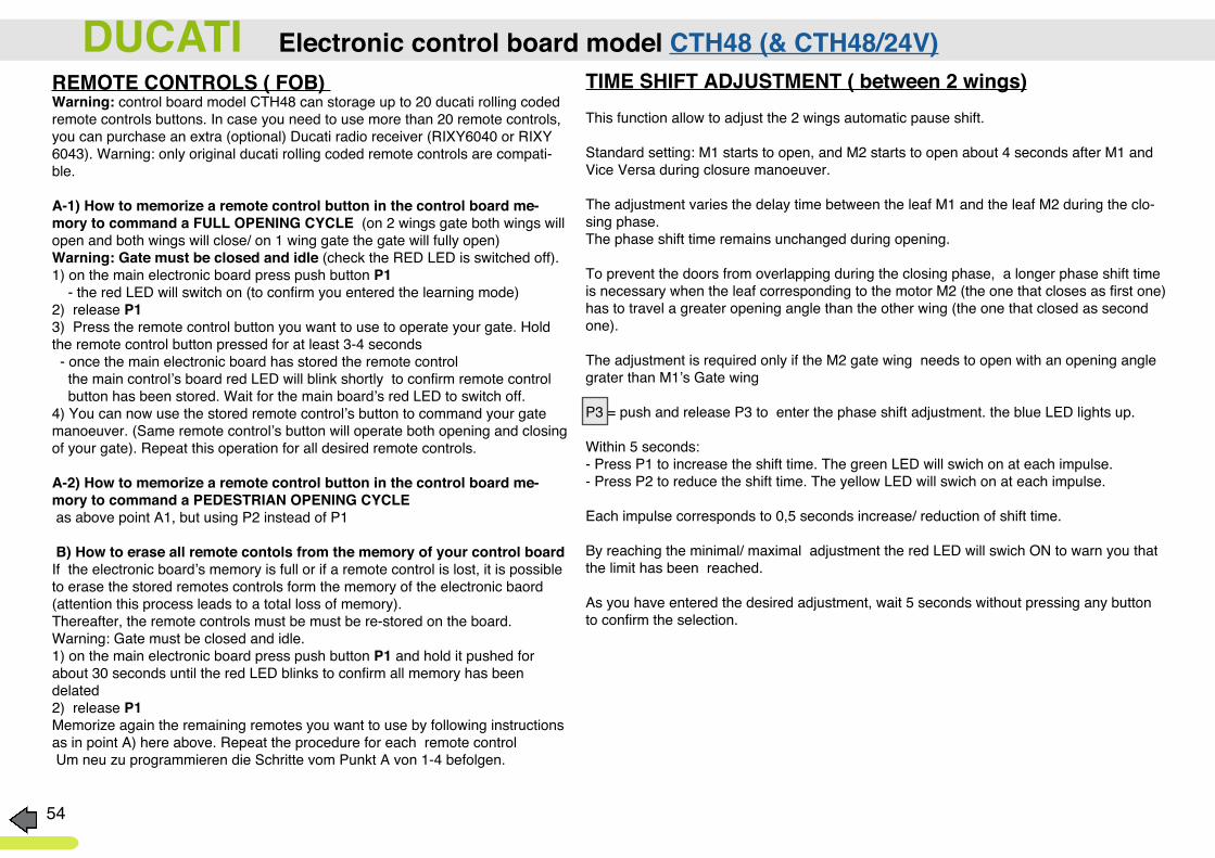
DUCATI Electronic control board model CTH48 (& CTH48/24V)REMOTE CONTROLS ( FOB) Warning: control board model CTH48 can storage up to 20 ducati rolling coded remote controls buttons. In case you need to use more than 20 remote controls, you can purchase an extra (optional) Ducati radio receiver (RIXY6040 or RIXY 6043). Warning: only original ducati rolling coded remote controls are compati-ble.
A-1) How to memorize a remote control button in the control board me-mory to command a FULL OPENING CYCLE (on 2 wings gate both wings will open and both wings will close/ on 1 wing gate the gate will fully open)Warning: Gate must be closed and idle (check the RED LED is switched off).1) on the main electronic board press push button P1 - the red LED will switch on (to confirm you entered the learning mode)2) release P13) Press the remote control button you want to use to operate your gate. Hold the remote control button pressed for at least 3-4 seconds - once the main electronic board has stored the remote control the main control’s board red LED will blink shortly to confirm remote control button has been stored. Wait for the main board’s red LED to switch off.4) You can now use the stored remote control’s button to command your gate manoeuver. (Same remote control’s button will operate both opening and closing of your gate). Repeat this operation for all desired remote controls.
A-2) How to memorize a remote control button in the control board me-mory to command a PEDESTRIAN OPENING CYCLE as above point A1, but using P2 instead of P1
B) How to erase all remote contols from the memory of your control boardIf the electronic board’s memory is full or if a remote control is lost, it is possible to erase the stored remotes controls form the memory of the electronic baord (attention this process leads to a total loss of memory). Thereafter, the remote controls must be must be re-stored on the board. Warning: Gate must be closed and idle.1) on the main electronic board press push button P1 and hold it pushed for about 30 seconds until the red LED blinks to confirm all memory has been delated2) release P1Memorize again the remaining remotes you want to use by following instructions as in point A) here above. Repeat the procedure for each remote control Um neu zu programmieren die Schritte vom Punkt A von 1-4 befolgen.
TIME SHIFT ADJUSTMENT ( between 2 wings)This function allow to adjust the 2 wings automatic pause shift.
Standard setting: M1 starts to open, and M2 starts to open about 4 seconds after M1 and Vice Versa during closure manoeuver.
The adjustment varies the delay time between the leaf M1 and the leaf M2 during the clo-sing phase. The phase shift time remains unchanged during opening.
To prevent the doors from overlapping during the closing phase, a longer phase shift time is necessary when the leaf corresponding to the motor M2 (the one that closes as first one) has to travel a greater opening angle than the other wing (the one that closed as second one).
The adjustment is required only if the M2 gate wing needs to open with an opening angle grater than M1’s Gate wing
P3 = push and release P3 to enter the phase shift adjustment. the blue LED lights up.
Within 5 seconds:- Press P1 to increase the shift time. The green LED will swich on at each impulse.- Press P2 to reduce the shift time. The yellow LED will swich on at each impulse.
Each impulse corresponds to 0,5 seconds increase/ reduction of shift time.
By reaching the minimal/ maximal adjustment the red LED will swich ON to warn you that the limit has been reached. As you have entered the desired adjustment, wait 5 seconds without pressing any button to confirm the selection.

55
Power supply by emergency back-up batteryUse a fully charged 12V min.7A batteryUse the 2 wires welded to the backside of the control board CTH44 to connect the battery to the board. WARNING: respect cable polarity red cable= battery positive pole (+); blue cable = battery negative pole (-) In case of main ac power suppluy failure, the back-up battery will ensure autonomous use for up to 4 days.
Power supply by Solar panel and battery: 100% autonomous useUse a fully charged 12V min.7A batteryUse the 2 wires welded to the backside of the control board CTH44 to connect the battery to the board.WARNING: respect cable polarity red cable= battery positive pole (+); blue cable = battery negative pole (-)
Connect a 12V min.10W solar panel to the board CTH44 by means of bipolar (outdoor use min. 0,5mmq cable) with the utmost attention to the polarity of the terminals: connector n° 11 - solar panel negativeconnector n° 12 + solar panel positive
The solar module should be directed towards the south (see also notes installation and positioning) and in a well-lit place. Avoid shadow zones, which reduce the load capacity considerably.It is recommanded to install the solar panel not over 10-15 meters from the electronic board to prevent unnecessary electrical losses.
The following table shows an estimated calculation of the autonomy in non-ideal weather conditions ( winter cloudy weather) by use of a 10W solar panel and 7A battery.The autonomy increases in case of use of to larger capacity battery (ex. 12V 12A) and larger solar module (ex. 12V 20W). Instead of using a larger solar module, on CTH44 it is possible toadd a second solar panel toincrease the charge capacity.
WARNING: by increasing the watt of the solar module, the battery capacity must also be increased.For example: if using 20W 12V solar panel requires a 12V min 12V battery.
NOTE: you can also wire main ac power supply through a switch. The AC power supply can be switched on to recharge the battery in case of needs, DO not power the board by both solar panel and AC power supply at same time.
DUCATI Electronic control board model CTH48 (& CTH48/24V)
TABLE- GATE
Stand-by con-
sumption ( A)
daily con-sumption
Consumption for a compleete cycle (open+ close), (A)
Suumption of total n° of daily cycles (open+close)
total daily con-sumption (A)
average charge of a 10W 12V solar panel (A /hour) in non ideal
weather
hypotesis of lixght expo-sure ( hours/per day)
Tolal recharge capacity (A)
balance between con-sumption and recharge
Board CTH48
1 wing 0,007 0,16
0,012 60 0,880,3* 5 1,5
+ 0,622 wings 0,024 50 1,36 + 0,14

56
Model 6204 = small 4 buttons rolling coded remote control. black color FOBBattery: 1 x 27A 12V gespeist
Model 6203 ROL = 2 buttons rolling coded remote control. Blue with blue button FOB. Battery: 1 x 12V C-23A
Model 6203 P = 2 buttons rolling coded remote control. Blue with red button FOB. Battery: 1 x 12V C-23A gespeist
The DUCATI radio rolling coded transmitters (FOB), featuring a unique “rolling code” radio protocol are compatible with all Ducati rolling coded openers (CTH electronic boards). With over 3 billions of continuously changing combinations, they ensure maximum protection against radio interferences. Frequency:433,92MHzAny of the rolling coded remote controls is compatible with all models of rolling coded Ducati’s openers. Yoy can combine and use different remote control model on the same openerEach transmitter button is factory programmed with a unique code. Ducati’s rolling code remote controld cannot be cloned.Each button on the remote control can be used to operate a different function ( for example tone button to command fullopening cycle, and second button to command pedestrian opening cyle) or different openers ( for example one button to command your gate opener and the second button to command a garage door opener
Warning: The memory of the control board of your opener can store up to 10-20 codes depending on the model (check the maximal storage capacity of your electronic board). If you need a larger number of remote controls you can purchease an optional external receiver (RIXY6040 o RIXI 6043). The external receiver can be also used to command other brand automatic systems with a Du-cati rolling coded remote control. To operate your “DUCATI” opener with your DUCATI remote control you must memorize the remote control code on the electronic board of your opener. WARNING: Operate adjustments and settings only with garage door or gate in closed postion.
A) How to memorize (store) the remote control code inside the electronic board of the opener for full opening cycleThe door must be closed and idle.- Press button P1 on the electronic board. The red LED switches on.- Release button P1 and immediately press on the buttons of the remote control that you wish to use to operate the device. Hold the remote button pressed for about 4 sec. - the LED light on the electronic board will quickly blink to show the procedure has been completed. Wait until the LEd switches off.- Press again the memorized remote control button, the opener will start an manoever
A2) ow to memorize (store) the remote control code inside the electronic board of the opener for pedestrian opening cycle ( only 1 wing will partially open)Please check the specific instructions for each specific electronic board model.to resume: On board model CTH41: this feature is not available.On board model CTH42: like the procedure at point A1, but use the J1 button instead of the P1 buttonOn board model CTH44: follow the instructions of point A1, but instead of just pressing P1, press and hold P1 and simultaneously press P2 and then release both buttons.On board model CTH48: follow the instructions of point A1, but use the P2 button instead of the P1 button
Warning: when opening your gate in pedestrian mode, the gate must be closed with pedestrian mode before to proceed with a full opening cycle command.
B) How to erase the codes from the control board ( total loss of all previously stored remote controls)To deactivate any unwanted remote, erase its memory from the electronic board of your opener as following (all remote control codes memorized will be delated):- The door must be closed and idle.- Press button P1 for about 30 sec. until the red LED blinks- Release P1. All codes have been ereased and the memory of your control board is ready to memorize new remote controls ( fol-low insttructions as on point A
DUCATI Rolling code REMOTE CONTROLS (Ducati rolling code)
Model 6202 = small 2 buttons rolling coded remote control. in blue, yellow, red, black color available.Battery: 2 x CR2016 3V
Model 6208 = small 4 buttons rolling coded remote control. white/black color FOBBattery: 2 x CR2016 3V
6203R 6203P 6204 6202 6208