12 en route to scientific automationcdn.pc-control.net/pdf/032007/pcc_0307_e.pdf3 | 2007 interview...
TRANSCRIPT

3 |
2007
ww
w.p
c-co
ntr
ol.
net
interview
research &development
title
12
19
6
En route to Scientific AutomationInterview on innovations and trends
with managing director Hans Beckhoff
PC-based control with Multi-Core™ TechnologyIntel® Multi-CoreTM Technology provides higher performance
in PC-based automation technology.
“Global Control” for plasma cutting machinesMesser Cutting Systems rely on PC-based control by Beckhoff
for global control concept.
PCcontrol_3_07_GB_191107.qxd 19.11.2007 15:29 Uhr Seite 1

PC Control 03 | 20072 editorial
“Global Control”
Everyone is talking about global markets: Opportunities and risks are dis-
cussed; challenges and opportunities are weighed up. With a good por-
tion of common sense, it becomes clear that far-off markets have their
peculiarities, but they also offer opportunities for growth and integration
as sales markets.
Machine producers and manufacturing plants follow their customers all
over the world to their locations and sales markets. As a result, there is
growing demand for a uniform, worldwide usable, understandable, easy-
to-maintain and accepted automation technology for machines and pro-
duction plants: a “Global Control” – an automation platform for the
world.
Such a technology gives operators of machines and production plants the
flexibility to install freely at the necessary locations all over the world.
Investments in machine equipment, spare parts and the training of oper-
ators and maintenance personnel are utilized more efficiently, they do not
need to be repeated for several platforms and they remain permanently
usable worldwide.
A uniform “Global Control” also makes it possible for machine and prod-
uct manufacturers to produce their respective product efficiently and at
even lower cost. Cost drivers can be eliminated: The parallel integration
of different automation platforms requires time and creates high engi-
neering costs with no added value. The resources wasted in this process
can be better used for the rapid innovation of functions: time to market
for innovations wins in the competition for customers.
Taking the current technological lead of open automation technology in
the worldwide competition of automation systems into account, the opin-
ion is justified that the use of globally widespread standards from the
computer industry – used and integrated in the correct way – has the po-
tential to become such a “Global Control”. Above all, it will find the
acceptance that proprietary total solutions are lacking – must be lacking
– in one region of the globe or another. The world understands “the PC”
and Windows in a way that integrates, creates the necessary trust and
builds bridges, regardless of the region or culture in which one moves:
People everywhere know and use the personal computer like a global
culture, and that is a good platform for a “Global Control”.
The widely ramified standards in automation technology merge ideally in
an open manner on such a global platform – the compatible Industrial PC
or its scalable version as embedded controller. There may be a preference
here and there for one programming language or another (whereby
IEC 61131-3 is the global standard for machine programming) or an I/O
network (it will be Ethernet, reduction to the market-relevant systems is
in full swing here, too), but the world meets on the PC. In a “Global Con-
trol” all insufficiently interoperable standards from the various automa-
tion market segments can coexist and exchange data. The ideal “Global
Control” is more than just a superficial call for the standards of the glob-
al PC market; it must be supplemented by the integration of the most im-
portant standards from the world of automation in order to provide every
user in the automation world with a familiar access point to their own
version of “Global Control”. The automation solution for a “Global Con-
trol” therefore offers uniform configuration, communication, program-
ming tools and scalable hardware, and beyond that it must support the
diverse market-relevant automation standards for different applications
and regions of the world, for industrial networks, communication proto-
cols, programming languages and operating system integration. With
such a platform the focused, continual further development and imple-
mentation of know-how worldwide will succeed for subsequent applica-
tion: in this way the world of automation technology will meet at the
“Global Control”
Gerd Hoppe, Corporate Management, Beckhoff Automation
PCcontrol_3_07_GB_191107.qxd 19.11.2007 20:33 Uhr Seite 2

3 contentsPC Control 03 | 2007
18 | Beckhoff extends servomotor range
with the AM3500 series
21 | Integrated IPC series using
CoreTM Duo/CoreTM2 Duo
19 | research & developmentPowered up PC-based control with
Multi-CoreTM Technology
24 | worldwideKatzenberger, Austria: TwinCAT helps elimi-
nate “bottleneck” in production process
27 | IPC-supported control of decentralized
Servo Drives using XFC
32 | Beckhoff creates Chinese subsidiary
34 | Herkules, Germany: TwinCAT ensures
the perfect finish
38 | IEF Werner GmbH, Germany: Wheel gauging
systems are the measure of success
4 | newsSPS/IPC/DRIVES 2007
5 | Beckhoff Denmark: Minister for Trade
and Industry visits HI Industri 2007
6 | title“Global Control”: Messer Cutting
Systems rely on Beckhoff technology
for global control concept
12 | interviewHans Beckhoff on innovations and trends:
En route to Scientific Automation
15 | productsBus Terminals record differential and
absolute pressures
16 | CX9010 Embedded PC compliments the
spectrum of Windows CE controllers
17 | New I/O Bus Terminals for building automa-
tion: dimmer terminal with 600 W and wear-
free 24 V AC/DC output terminals
40 | LightHive exhibition, Great Britain:
Light show or light reality?
42 | Huhtamaki, Netherlands: PC Control and
EtherCAT for premium packaging
44 | Accionia S. A., Spain: Tunneling through
mountains using Beckhoff technology
46 | Proventia, Finland: EtherCAT-based
robot control
48 | ETGETG at SPS/IPC/DRIVES
EtherCAT as communication technology
for SERCOS and CANopen drive profiles
now International Standard
EtherCAT approved by SEMI
50 | eventsTrade shows 2008
51 | communicationImprint
PCcontrol_3_07_GB_191107.qxd 19.11.2007 15:30 Uhr Seite 3

Between 27 and 29 November 2007 around 1,280 exhibitors will present
products, trends and solutions at SPS/IPC/DRIVES in Nuremberg/
Germany. The fair covers ten exhibition halls with a total floor area of
more than 85,000 m2.
The complete range of Beckhoff products and PC-based automation
solutions will be on show at the 1,000 m2 Beckhoff stand in Hall 7,
Booth 406. The stand booth is split into different sections for IPC, I/O,
Motion, Automation plus the Solution Forum, where industry-specific
solutions will be presented.
Performance in AutomationUnder the heading “Performance in Automation” Beckhoff will present
its integrated hardware and software platform for Intel® CoreTM Duo or
Intel® CoreTM2 Duo processors, which enables further performance increas-
es for PC-based control applications. Users can select the right IPC for
their application from 13 different IPC device families offering CoreTM Duo
performance, ranging from Panel PCs to the ultra-compact control cabi-
net PCs. The TwinCAT automation software fully supports the CoreTM Duo
technology and automatically detects CoreTM Duo systems.
XFC technology (eXtreme Fast Control Technology) was designed for ap-
plications with extreme performance and precision requirements. XFC
represents a control technology that enables very fast and highly deter-
ministic responses. Users benefit from new options for enhancing the
quality of their machines and reducing response times. XFC offers gains
in performance and efficiency for high-end and standard machines.
EtherCAT-based automationEtherCAT – the fastest Industrial Ethernet technology – has become es-
tablished: Beckhoff offers the complete range of EtherCAT products. All
devices support all EtherCAT topology types, i.e. line, ring, tree, star, in-
cluding combinations of different types and configurations with line
redundancy. Users can choose between the extended EtherCAT Terminal
system, Bus Couplers based on glass fibre technology for particularly long
network distances, bridge terminals connecting several EtherCAT seg-
ments, and Safety over EtherCAT components. However, the Beckhoff phi-
losophy of open control technology goes even further: New interfaces for
other market-relevant Industrial Ethernet solutions complement the
range of products. Special highlights are the PROFINET gateway and the
real-time Ethernet port multiplier. With TwinCAT and the port multiplier
several EtherCAT segments – including configurations with line redun-
dancy – can be operated via an Ethernet interface. The system is also suit-
able for other Ethernet protocols, with synchronisation available based on
the respective real-time capability.
The Motion Forum will focus on the AX5000 EtherCAT drives with inte-
grated safety functions. The Beckhoff presence at SPS/IPC/DRIVES is
rounded off with participation on the EtherCAT Technology Group stand,
where more than 50 exhibitors will present their real-time Ethernet solu-
tions for EtherCAT.
4 news PC-Control 03 | 2007
SPS/IPC/DRIVES 2007
PCcontrol_3_07_GB_191107.qxd 19.11.2007 15:30 Uhr Seite 4

The HI Industri 2007 took place from the 4th to 7th of September in Herning,
Denmark. With around 1,000 exhibitors, this trade show ranks as one of the
most important industrial trade shows in Scandinavia. The Danish Minister for
Trade and Industry, Bendt Bendtsen, also made a tour of the trade show in or-
der to inform himself of the latest technological developments first hand. Claus
Clausen, managing director of Beckhoff Denmark, and sales engineer Søren
Mørk welcomed Bendt Bendtsen and the managing director of the exhibition
center, Georg Sørensen, to the Beckhoff trade show booth. Beckhoff presented
their product lines with their comprehensive product range of Industrial PCs, I/O
components, drive technology and automation solutions.
“We were able to present several innovations to the trade show visitors. A par-
ticular highlight was the XFC technology, which created great interest,” says
Claus Clausen, summarizing the success of the trade show. “As the previous
years have shown, the HI Industri is an important forum for us to strengthen
our relationships with existing customers and to establish new contacts. We are
confident that we will further expand our strong position in the Danish market
in the coming years.”
5 newsPC-Control 03 | 2007
Beckhoff Denmark: Minister for Trade
and Industry visits HI Industri 2007
From left: Georg Sørensen, managing director of the exhibition center, Claus Clausen,
managing director of Beckhoff Denmark and the Danish Minister for Trade and Indus-
try, Bendt Bendtsen, at the Beckhoff trade show booth at the HI Industri 2007.
The main information at a glance:| SPS/IPC/DRIVES 2007, Nuremberg Exhibition Centre, Germany
| 27. – 29. November 2007
| Opening hours:
Tuesday and Wednesday 9am – 6pm,
Thursday 9am – 5pm
| Beckhoff main booth: hall 7, booth 406
Beckhoff at partner booths:| EtherCAT Technology Group, hall 6, booth 309
| PROFIBUS user organisation, hall 6, booth 210
Further Information:
www.mesago.com/sps/
www.beckhoff.com/sps2007/
PCcontrol_3_07_GB_191107.qxd 19.11.2007 15:31 Uhr Seite 5

6 title PC Control 03 | 2007
‘Global Control’ for plasma cutting machines
Messer Cutting Systems rely on Beckhoff technology for global control concept
PCcontrol_3_07_GB_191107.qxd 19.11.2007 15:31 Uhr Seite 6

At the beginning of the year 2000, the decision was made to realize a
globally uniform control concept on a suitable platform. To this end, as
Burkhard Fenner reports, around 50 suppliers of CNC control systems
were reviewed, of which almost 10 were selected for the final round of
evaluation. A team of colleagues from the United States and Germany
carried out detailed tests, in particular with regard to hardware condi-
tions, CNC functionality and the standardization of the PLC. During this
procedure, Beckhoff emerged as a suitable supplier, so that further con-
crete tests, in particular in the EMC-critical environment of plasma cut-
ting machines, were carried out in 2001. Since the start of the project
in summer 2002, Messer Cutting & Welding and Beckhoff have been
working jointly on the realization of ‘Global Control’, which has been
in use worldwide since the successful introduction of the concept in
April 2004. “The first contact with Messer USA was initiated by the US
branch of Beckhoff. Both sides called in their respective head offices in
Germany, which ultimately developed into a particularly successful in-
ternational project that led to many additional projects, even after the
initial success from the first series introduction,” explains Frank Sauer-
essig, CNC expert at Beckhoff Germany.
‘Global Control’ concept
The Messer Cutting & Welding GmbH uses the term ‘Global Control’ to
describe the worldwide uniform control concept for their plasma
cutting machines that is equipped with Beckhoff technology. Messer
Cutting & Welding uses various Beckhoff Industrial PCs as well as the
TwinCAT CNC automation software. The machine is operated via a cus-
tomer-specific Control Panel, which has been specially designed to
Robust plasma cutting technology for essentially any application char-
acterizes the range of machines created by Messer Cutting & Welding
GmbH. The machines are produced at four locations: in Groß-Umstadt
(Germany), in Menomonee Falls, Wisconsin (USA), in Kunshan City (Chi-
na), as well as in São Paulo (Brazil). Distribution takes place globally.
The basic principle of the range of machines is similar, and hence it was
only natural that the control technology should also be globally uni-
form.
Although Messer Cutting & Welding GmbH mostly builds customer-spe-
cific machines, which differ from one another with regard to their di-
mensions, the machine type, number of cutting systems and other de-
tails, they have been successful in designing all of them with a uniform
control system. Naturally, the applicable worldwide machine directives
must be taken into account. The Global Technology Team is responsible
for maintaining this high standard and for the dynamic reaction to
changes in the market. Burkhard Fenner, Technical Director and Man-
ager of Automation Technology, as well as the Project Managers Ingo
Göller and Mark Ringgenberg manage the team, which includes addi-
tional employees of the internationally operating company from Ger-
many, the United States and China.The main development extends over
a period of around two years.
Control technology by Beckhoff
Control technology has a long tradition at the Messer Cutting & Weld-
ing GmbH. Beginning in the 80s, the company developed CNC con-
trollers and was one of the first distributors of CNC plasma cutting ma-
chines worldwide.
As leading manufacturers of customer-specific machines for thermal cutting applications, the Messer Cutting & Welding GmbHworldwide relies on a uniform control concept. A PC-based CNC system controls all of the company’s oxy-fuel and plasma cutting systems, bevel-cutting units and marking systems.
7 titlePC Control 03 | 2007
PCcontrol_3_07_GB_191107.qxd 19.11.2007 15:31 Uhr Seite 7

meet Messer Cutting & Welding GmbH’s needs. The machine peripherals are con-
nected to the Bus Terminal I/O system, which is linked to the Industrial PC via the
Lightbus. The number of I/O connections is dependent on the machine type and
starts with 32 I/Os for the smallest machine. Both digital and analog I/Os – in-
cluding encoder inputs – are used.
Among others, the Digital Compact Servo Drives of the AX2500 series with cor-
responding Servomotors are used as axis drives, which can also be connected to
the Lightbus protocol.
Lightbus is used due to its high data transfer rate and fiber optic-based interfer-
ence immunity, which is particularly important for plasma cutting machines. “Cur-
rently, we are testing the increased use of EtherCAT,” says Ingo Göller. He fore-
sees further advantages from this fieldbus technology: “The even higher per-
formance and optimum diagnostic properties as well as higher flexibility in the
hardware range and architecture speak for EtherCAT.”
The ScopeView function is one of the most important TwinCAT properties that
Messer Cutting & Welding GmbH utilizes. “Using TwinCAT ScopeView, we can ac-
quire and retrace data in real-time, allowing us to keep an eye on the machine
performance and impending errors so that we can take the necessary measures
PC Control 03 | 2007
Plasma cutting machines by Messer Cutting & Welding GmbHDespite the uniform basic principle, the plasma cutting machines from Mess-
er Cutting & Welding GmbH are for the most part customer-specific designs.
For example, a gas cutting machine can be up to 60 meters long and equipped
with several tool carriages.
The cutting machines are moved along the longitudinal axes by means of
toothed racks and motor-gearbox units. “Linear drives don’t come into ques-
tion for us, because we sometimes have tracks of up to 60 meters in length
and linear drives are simply too expensive for such lengths,” explains Ingo
Göller. In addition to this, the operating conditions for linear motors could be-
come negatively affected due to the metal dust that is created.
Up to sixteen so-called carriages can be built on a plasma cutting machine,
each of which has at least one process tool. According to the process re-
quirements of the customer, several tools can be at disposal at the carriage.
With regard to the process technology, distinction is made between autoge-
nous, plasma and laser cutting. Although the Messer Cutting & Welding
GmbH constructs the latter almost exclusively in the area of large-sized met-
alworking, the machine construction concepts for autogenous and plasma
cutting are available in many metal working sizes. As a result, there are cus-
tomer-specific gantry or flat bed machines with three-axis bridge superstruc-
tures. One or more cutting heads with one or more axes, including the asso-
ciated energy supply, are fastened to these machines.
The cutting machines by Messer Cutting & Welding are usually used to cut
and mark thick sheet metal with both normal vertical cuts and beveled cuts.
To this end, the cutting or marking tool is controlled via the classic X-, Y- and
Z-axes, whereby the Z-axis merely controls the height position, assisted by a
collision or distance detector. In the case of plasma cutting, this process takes
place on the basis of arc-dependent height scanning. The sheet metal thick-
ness range starts from 0.5 mm and extends to 150 mm, however 3 mm to 70
mm ranges are typical.
in good time. Besides that, the system provides us with exact performance data,
which we could only surmise in the past,” says Mark Ringgenberg.
Software CNC
TwinCAT CNC was specially adapted for Messer Cutting & Welding GmbH to meet
the needs of thermal cutting technology. “We developed the control software and
the entire user interface ourselves,” reports Ingo Göller. “In this way, we achieve
high flexibility to react quickly and optimally to new requirements.”
Messer Cutting & Welding GmbH currently uses up to 18 interpolated CNC axes
for the drive axes and the special bevel units. So-called "DAFL units" are used in
the autogenous area. This fully-rotatable unit with several torches has two axes,
which are able to perform a lateral offset and two additional tilting axes for the
adjustment of the torch angle. Highly complex multi-bevel cuts can be executed
in one working step using this unit.
For such applications, the so-called "skew rotator" – similarly, a fully-rotatable
unit with just one tilting axis and one track axis – that was developed globally
for use in plasma cutting. TwinCAT CNC can prove all of its performance capabil-
8 title
Skew rotator
PCcontrol_3_07_GB_191107.qxd 19.11.2007 15:31 Uhr Seite 8

ities in the field of interpolation and real-time transformation during these
processes. The operating software developed by Messer Cutting & Welding GmbH
is based on the Microsoft .NET framework. As Ingo Göller explains: “We use
Microsoft Windows XP Professional as our operating system to offer the option
of integrating the control into clients’ networks.”
‘Global ControlS’
Alongside ‘Global Controlplus’, Messer Cutting & Welding GmbH has introduced in
the ‘Global ControlS’ a further controller category for smaller machine types. The
design is based on a Beckhoff Panel-PC, which is mounted directly on the oper-
ating unit. EtherCAT functions as the communication bus and Beckhoff Bus Ter-
minals are used for the I/O system.
“The ‘Global ControlS’ is based worldwide on a standardized software and hard-
ware platform,” explains Ingo Göller. For Burkhard Fenner, this is part of the con-
tinuous process optimization. “The order completion time that was required ear-
lier was drastically reduced.” According to Fenner, ‘Global Control’ has therefore
become an important part of the integrated production concept.
9 titlePC Control 03 | 2007
Customer-specific operating conceptThanks to the use of customer-specific Control Panels manu-
factured by Beckhoff, Messer Cutting & Welding is able to
give the operator interface an aesthetic and user-friendly de-
sign. “The personal touch is becoming a more and more im-
portant factor for our clients; so the 'Messer look' is very im-
portant for a product that is looked at as often as the HMI is.
There are a lot of other companies that use Beckhoff Control
Panels, but our specific panel design is unique in the indus-
try,” explains Mark Ringgenberg.
The operating panel is tailored entirely to Messer Cutting and
Welding GmbH’s needs. “All the necessary hardware operat-
ing elements, e.g. the emergency stop button, are located on
the front of the panel,” says Ingo Göller. A joystick enables
the movement of the machine in eight directions. The speed
and the parameters can be changed by a handwheel.
Depending on the number of torch heads that a machine has,
up to six switches serve for the height adjustment of the cut-
ting tools and can be mounted on the main panel alongside
the stop and start switches.
An additional operating panel is available for further cutting
tools and special functions. Since the plasma cutting ma-
chines do not operate exclusively in the ‘2-meter class’ and,
due to their area dimensions, larger distances between the
control cabinet and the operating panel play a part, the in-
terface between the two units is of further importance: “Us-
ing CP-Link, an operating panel can be situated up to 100 m
away from the CNC controller. If USB functionality is required
in addition, an operating panel with a DVI/USB Extended in-
terface can be used up to a distance of 50 m,” comments
Frank Saueressig.
Messer Cutting & WeldingGmbH is a traditional German
engineering company that can
look back on over one hundred
years of history. With over 600
employees at four sites world-
wide, we produce plasma cut-
ting machines to meet the high-
est demands of the metalwork-
ing industry. The machines are
used in all segments of thermal
cutting and in many cases repre-
sent the first and sometimes the
most important step in a modern
production process.
Project manager Ingo Göller,
Messer Cutting & Welding GmbH
Burkhard Fenner, Technical Director,
Messer Cutting & Welding GmbH
Project manager Mark Ringgenberg,
MG Systems & Welding, Inc. USA
Frank Saueressig, Manager Office Balingen,
Germany, and CNC expert at Beckhoff
DAFL unit
PCcontrol_3_07_GB_191107.qxd 19.11.2007 15:31 Uhr Seite 9

Transparency in operation and service
A high degree of operational safety exists for the operator of the plasma cutting
machine. Depending on the operating mode of the machine, the functions for
each respective working step, e.g. hole punching or similar, are illustrated on the
screen together with the associated operating buttons. Once the operating con-
dition changes, function buttons that can no longer be used are masked out. “This
design leads to a very short learning phase. For further simplification, we have
used an absolutely identical user interface globally,” says Ingo Göller, explaining
the advantages.
The ‘Global Control’ solution must naturally also be usable by service personnel.
“We have been offering Teleservice functionality since 1989,” Ingo Göller em-
phasizes. However, Teleservice at Messer Cutting is also more than the standard
web-based access of today.As Göller explained, Messer’s Global Technology Team
is currently developing a special concept for secure access.
Globalization of the supply chain
The global orientation of his client, Messer Cutting & Welding GmbH, is extremely
interesting to Frank Saueressig: “Beckhoff supplies the entire platform for ‘Glob-
al Control’ worldwide and, in fact, from each respective Beckhoff branch office.
Our colleagues in the USA and China supply the same components that we do in
Germany. We have uniform article numbers for the components that are supplied
10 title PC Control 03 | 2007
Trident Steel from South Africa relies on Messer technologyThe world’s largest high-performance plasma cutting ma-
chine is located in South Africa: At Trident Steel, two
8.8 meter wide and 78 meter long OmniMat® cutting sys-
tems developed by Messer Cutting & Welding ensure eco-
nomical sheet metal processing. A decisive advantage of
the new plasma technology is the constantly outstanding
cutting quality. The stable construction of the OmniMat®
plants ensures reliable results: low-play, high-power AC
drives guarantee positioning speeds of up to 35 m/min
with high acceleration and absolute precision.
In addition, the new machines do not need to be moni-
tored by the operator during the cutting process: The
processes run fully automatically. As a result, there is
more time to prepare the next process, which further im-
proves the production flow and quality. "'Global Control'
is at the heart of this automation. It makes the work much
easier, because it controls virtually all of the processes
itself. It is such a user-friendly design that it can be mas-
tered even after a short training period,” says Jimmy
Claven, Divisional Director at Trident Steel.
By using three HPR260 plasma cutters simultaneously, Trident Steel
achieves high quality and outstanding productivity.
PCcontrol_3_07_GB_191107.qxd 19.11.2007 15:32 Uhr Seite 10

11 titlePC Control 03 | 2007
Precise, rapid cuts proceed fully automatically thanks to Messer’s
'Global Control'.
to Messer Cutting & Welding and that doesn't just simplify cooperation, but safe-
ty as well.” Ingo Göller is also enthralled by the positive cooperation: “We have
attained the goal that we jointly set four years ago and we appreciate the disci-
pline of our supplier too because without it, ‘Global Control’ would not be feasi-
ble in the long run.”
Open control platform for all cases
Messer Cutting & Welding GmbH’s range of machines places very large demands
on the control equipment: on the one hand, a large number of units, including
their variants, must be adapted into the machine superstructures; on the other
hand – considered from an operations point of view – complex positioning tasks
with interpolation and the interaction of several drives must be realized. In addi-
tion, communication technology and the harsh operating environment of plasma
cutting technology place particular demands on the control system.
The complexity extends even further for Ingo Göller: “The Beckhoff platform of-
fers a high degree of freedom, for example in the driving of axes by the PLC with
the transfer of the transformations from the CNC to the PLC and vice versa. It is
therefore possible to execute a part of the CNC tasks in the PLC and subsequently
to transfer the functionality from the PLC back to the CNC, e.g. after setting up
or offsetting a machine.”
“Messer Cutting & Welding’s requirements for the new control concept were
enormously high because it wasn’t just about using a standard platform, but
about a worldwide, uniform, high-quality CNC controller,” says Frank Saueressig
in summary. As Burkhard Fenner mentions, the close cooperation and Messer Cut-
ting’s profound know-how were decisive for success: “We were able to bring in
our special CNC functionality and avoid the otherwise usual ballast.” Besides
these aspects, there were further reasons for the company to use Beckhoff tech-
nology as a platform. “The high degree of standardization, from the Industrial PC
level through the modularity of the I/O system to the bus design, operating pan-
el and drive technology, corresponds to our needs for a scalable control solution
for our customer-specific machines,” says Fenner. It was and is the particular de-
sire of the thermal cutting technology specialists to integrate their own know-
how optimally in the machines in the form of the process and control technolo-
gy. “That is what makes the actual difference between you and your competitors,”
comments Fenner, “because this is the only way we can offer our customers a
process technology that allows them to cut faster, more accurately and more pro-
ductively.”
Messer Cutting Systems, Europe www.messer-cw.com
MG Systems & Welding, Inc. USA www.mg-systems-welding.com
Part 2 of the 'Global Control' report
follows in the 1/2008 PC Control issue.
PCcontrol_3_07_GB_191107.qxd 19.11.2007 15:32 Uhr Seite 11
Until the middle of this year, Beckhoff Automation showed an increase in sales of
22 %. “Consequently, we are expecting a turnover between 225 and 235 million
euros this year,” Hans Beckhoff revealed. The orders received have been consis-
tently excellent, both at home and abroad. “We are also doing well in the USA,
for example, with figures up 25 %” Beckhoff commented. Even though it has be-
come more difficult to make growth forecasts in view of turbulence in the finan-
cial world, no noticeable effects on growth can be detected. “There is no mea-
surable economic down-turn so far, although the general mood is a bit less se-
cure,” according to Beckhoff.
Creativity drives innovation
At Beckhoff, the entrepreneurial principle of organic growth still applies. Never-
theless, due to positive experiences with the purchase and integration of the two
embedded companies acquired last year, the managing director no longer wants
to rule out additional acquisitions. “However, acquisitions are not our primary
aim,” declared Beckhoff. The integration of Embedded-Logic Design & More, the
development specialist for motherboards, and BeDeHa, a specialist in BIOS soft-
ware, went well according to Beckhoff: “The integration was a success from a
business and personnel angle. It seems to me that the integration of personnel is
particularly important, but this was carried out without a hitch. Beckhoff prod-
ucts in the IPC field are now developed jointly by the development departments
in Verl and Münster, Germany.”
The two subsidiaries are run independently from a legal and organizational stand-
point. With Beckhoff Automation in the background, the two companies have
made large-scale and important investments in the area of research and devel-
opment and added staff since the take-over. So they are growing successfully. In
2008 they are due to move into a new building with a floor area of 1,200 m2.
“Both companies still work independently for a wide range of industrial clients,
one of which is, of course, Beckhoff,” the managing director added.
The success of the Verl-based company and the high level of innovative capabil-
ities are unprecedented in the automation industry. How can the long-term cre-
ativity required for this be guaranteed? “The primary requirement is selection of
the right staff,” declared Beckhoff. “A liberal and open corporate culture in which
technological development plays an important part also creates the right envi-
ronment for unconventional ideas. Added to this are secure jobs and an atmos-
phere free from ‘office fear’ that tolerates potential mistakes and encourages
gratification in the work,” is the company philosophy. “We cultivate open, infor-
mal communication in the company. Following extensive democratic discussion,
however, an executive decision is then made by the management responsible. In
this way, the company stays ‘on course’ while simultaneously involving a large
number of staff from all levels,” explained Beckhoff.
A leader in emerging technology areas
“It has been proven,” Beckhoff claimed, “that our kind of automation technolo-
gy also points to the path ahead for our partners in the automation market. To
date, we have launched a groundbreaking technology onto the market at least
every five years, even if in some cases its significance comes to light later.” The
managing director's view is that EtherCAT and eXtreme Fast Control Technology
(XFC) in particular are securing the current advantage for Beckhoff.
In an interview with Ronald Heinze, chief editor of openautomation, managing director Hans Beckhoff talks about new technologies and global development at Beckhoff in the run-up to the SPS/IPC/DRIVES show in Germany.
12 interview PC Control 03 | 2007
En route to Scientific Automation
Interview on innovations and trends with Hans Beckhoff
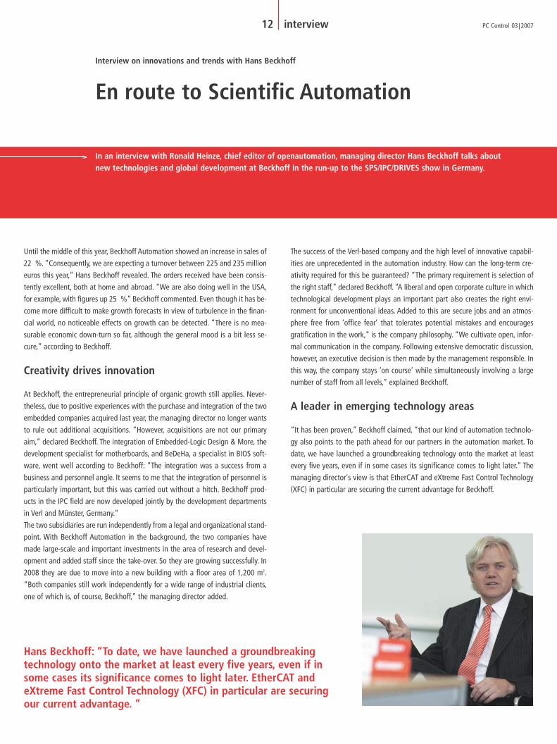
Hans Beckhoff: “To date, we have launched a groundbreaking technology onto the market at least every five years, even if in some cases its significance comes to light later. EtherCAT and eXtreme Fast Control Technology (XFC) in particular are securing our current advantage. ”
PCcontrol_3_07_GB_191107.qxd 19.11.2007 15:32 Uhr Seite 12

EtherCAT is developing in a particularly satisfying way. “The EtherCAT Technolo-
gy Group (ETG), with currently over 600 member companies in 35 countries, is
growing and thriving,” stressed Beckhoff. In addition to the ETG offices in China,
Japan and the United States, in November, another office will open in Korea. A
recent development is that EtherCAT has been approved as a SEMI standard
(E54.20) by Semiconductor Equipment and Materials International, the stan-
dardization association for the semiconductor industry. In addition, EtherCAT has
been a part of IEC 61158 since the 28th of September.
The field of functional security is also being systematically supplied with new
Beckhoff products. There is already a comprehensive range of TwinSAFE I/O ter-
minals available, which, according to Beckhoff, can accommodate 80 % of safe-
ty applications. Increasing numbers of users benefit from fieldbus-neutral safety
communication. "This even allows the connection of entire production lines with-
out any difficulty according to the functional security criteria,” added Beckhoff.
This advantage is particularly evident in modular machine design. The AX5000
drive with integrated safety functions will be presented at the SPS/IPC/DRIVES
show. Among other things, this drive controls the “safety-limited rotational
speed” and “safe torque” functions.
A safety technology collaboration with Bosch, 3S and Wago, which Beckhoff de-
scribes as a “welcome joint development” will also produce tangible results in
the near future: Beckhoff will present a Safety CPU at the next Hanover Fair. This
will make a modular safety PLC available.
Automation technology can achieve a great deal more
“Scientific automation is an exciting concept and should certainly stimulate
the imagination as our sector depends on innovation to a substantial degree,”
Beckhoff believes. In machine control technology, according to Beckhoff, there are
some “traditional” technology areas. Among these are sequential control, which
is implemented using a PLC, Motion Control that is implemented using motion
software or appropriate functional modules, as well as control technology and
HMI. All these areas used to be independent fields, which are today connected to
one another via hardware and software.
“Now there are newer technology areas beyond these traditional application ar-
eas”, continued Beckhoff.” For instance, measurement technology with appropri-
ate special devices is used for many high power applications.” It is therefore clear
to him that, “the integration of high-end measurement technology with automa-
tion control will form the basis of scientific automation.” This can begin, for exam-
ple, with vibration and oscillation analysis or statistical process data control, which
are integrated into the world of automation. But it can also be relevant for com-
pletely different fields. A start has been made: for example, TwinCAT ScopeView,
which is an integrated software oscilloscope, can provide exact data analyses. Ad-
ditional developments have been announced by the managing director for next
year:“At the next Hanover Fair, the scientific automation concept will spring to life.”
13 interviewPC Control 03 | 2007
“The integration of high-end measurement technology with automation control will form the basis of scientific automation.”
PCcontrol_3_07_GB_191107.qxd 19.11.2007 15:33 Uhr Seite 13

In Hans Beckhoff's opinion, scientific automation will be substantially shaped by
the user. “Each application area has its own engineering knowledge base and we
believe that our clients will use the opportunities provided by scientific automa-
tion for their own unique purposes. That is why it is important to develop wide-
ranging expertise in multiple sectors,” according to Beckhoff. He is convinced that
all automation technology suppliers will integrate many more scientific fields in-
to their product ranges in the future. “There is an exciting future,” he continued.
“Scientific automation is many-sided and demands imagination and creativity
from the engineers.” The basis of scientific automation is the continually increas-
ing performance of PCs, which Beckhoff is promoting vigorously with its own
motherboard development.
“We are developing our automation technology in several important directions,”
Beckhoff remarked. The targets here are ease of application, optimization of en-
gineering tools, a favorable price-to-performance ratio, high performance as well
as high efficiency, which leads to sustainability, among many other benefits. “The
concept of scientific automation represents our plan to make scientific progress
available through our technology to a wide range of application fields in a cost-
effective and simple way,” Beckhoff said. “Of course, we gain special satisfaction
from achieving technology milestones or exceeding performance limits. A great
success in this regard was with XFC technology, which now makes 100 µs I/O re-
sponse times available in control technology.” This ultra-fast control technology
is already being applied, as Beckhoff added, such as in the field of printing ma-
chines, injection molding systems and other rapid processing machines.
Modular engineering tools in development
Software also plays an important part. “With our TwinCAT product family, we al-
ready offer a software suite that has been growing steadily for years and enables
highly effective operation,” Beckhoff claimed. “The TwinCAT Workbench has been
expanded by numerous supplements over the last few years. Data from an ECAD
system can be simply transferred. These perpetually expanding programs can be
managed in a source code database.” Beckhoff currently has tools under devel-
opment that support modularization on the basis of IEC 61131-3 and enable
reuse of software as well as automatic generation of different versions. Moreover,
work has started on tools for module versions, maintenance of modules and proj-
ects, as well as those for ongoing simulation. “We believe that a modular, hier-
archical project structure with well defined and generally accepted module inter-
faces provides a powerful and manageable platform,” Beckhoff emphasized. “We
are developing the necessary tool set for this, which will be presented in 2008.
Modularization on a software basis is a significant and absolutely vital advance-
ment for automation.”
Published in openautomation 06/2007, VDE-Verlag, www.openautomation.de
“Of course, we gain special satisfaction from achieving technology milestones or exceeding performancelimits. A great success in this regard was with XFC technology, which now makes 100 µs I/O response timesavailable in control technology.”
14 interview PC Control 03 | 2007
PCcontrol_3_07_GB_191107.qxd 19.11.2007 15:33 Uhr Seite 14
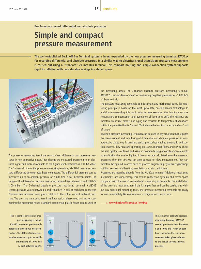
The pressure measuring terminals record direct differential and absolute pres-
sures in non-aggressive gases. They change the measured pressure into an elec-
trical signal and make it available to the higher level controller as a 16-bit value.
The 1-channel differential pressure measuring terminal, KM3701 measures pres-
sure differences between two hose connectors. The differential pressure can be
measured up to an ambient pressure of 7,000 hPa (7 bar) between points. The
range of the differential pressure measuring terminal lies between 0 and 100 hPa
(100 mbar). The 2-channel absolute pressure measuring terminal, KM3702
records pressure values between 0 and 7,000 hPa (7 bar) at each hose connector.
Pressure measurement takes place relative to the actual current ambient pres-
sure. The pressure measuring terminals have quick release mechanisms for con-
necting the measuring hoses. Standard commercial plastic hoses can be used as
the measuring hoses. The 2-channel absolute pressure measuring terminal,
KM3712 is under development for measuring negative pressures of -1,000 hPa
(-1 bar) to 0 hPa.
The pressure measuring terminals do not contain any mechanical parts. The mea-
suring principle is based on the most up-to-date, on-chip sensor technology. In
addition to measuring, this semiconductor also executes other functions such as
temperature compensation and avoidance of long-term drift. The KM37xx are
therefore wear-free, almost non-aging and resistant to temperature fluctuations
within the permitted limits. Status LEDs indicate the function or error, such as “out
of range.”
Beckhoff pressure measuring terminals can be used in any situation that requires
the measurement and monitoring of differential and dynamic pressures in non-
aggressive gases, e.g. in pressure tanks, pressurized cabins, pneumatic and suc-
tion systems. They measure operating pressures, monitor filters and sieves, check
the seal tightness of tanks and assist in position testing of construction elements
or monitoring the level of liquids. If flow rates are calculated from the measured
pressures, then the KM37xx can also be used for flow measurement. They can
therefore be applied in areas such as process engineering, systems engineering,
building services and heating, ventilating and air conditioning.
Pressures are recorded directly from the KM37xx terminal. Additional measuring
instruments are unnecessary. This avoids connection systems and saves space
compared with the use of conventional measuring instruments. The installation
of the pressure measuring terminals is simple, fast and can be carried out with-
out any additional mounting tools. The pressure measuring terminals are ready
for use immediately. No calibration or configuration is necessary.
www.beckhoff.com/BusTerminal
15 productsPC Control 03 | 2007
Simple and compact pressure measurement
Bus Terminals record differential and absolute pressures
The well-established Beckhoff Bus Terminal system is being expanded by the new pressure measuring terminal, KM37xxfor recording differential and absolute pressures. In a similar way to electrical signal acquisition, pressure measurementis carried out using a “standard” 24 mm Bus Terminal. This compact housing and simple connection system supports rapid installation with considerable savings in cabinet space.
The 1-channel differential pres-
sure measuring terminal,
KM3701 measures pressure dif-
ferences between two hose con-
nectors. The differential pressure
can be measured up to an ambi-
ent pressure of 7,000 hPa
(7 bar) between points.
The 2-channel absolute pressure
measuring terminal, KM3702
records pressure values between
0 and 7,000 hPa (7 bar) at each
hose connector. Pressure mea-
surement takes place relative
to the actual current ambient
pressure.
PCcontrol_3_07_GB_191107.qxd 19.11.2007 15:33 Uhr Seite 15
16 products PC Control 03 | 2007
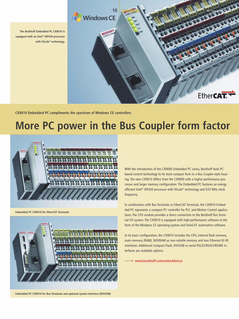
With the introduction of the CX9000 Embedded PC series, Beckhoff took PC-
based control technology to its most compact form in a Bus Coupler-style hous-
ing. The new CX9010 differs from the CX9000 with a higher performance pro-
cessor and larger memory configuration. The Embedded PC features an energy
efficient Intel® IXP420 processor with XScale® technology and 533 MHz clock
frequency.
In combination with Bus Terminals or EtherCAT Terminals, the CX9010 Embed-
ded PC represents a compact PC controller for PLC and Motion Control applica-
tions. The CPU module provides a direct connection to the Beckhoff Bus Termi-
nal I/O system. The CX9010 is equipped with high-performance software in the
form of the Windows CE operating system and TwinCAT automation software.
In its basic configuration, the CX9010 includes the CPU, internal flash memory,
main memory (RAM), NOVRAM as non-volatile memory and two Ethernet RJ 45
interfaces. Additional Compact-Flash, DVI/USB or serial RS232/RS422/RS485 in-
terfaces are available options.
www.beckhoff.com/embedded-pc
The Beckhoff Embedded PC CX9010 is
equipped with an Intel® IXP420 processor
with XScale® technology.
CX9010 Embedded PC compliments the spectrum of Windows CE controllers
More PC power in the Bus Coupler form factor
Embedded PC CX9010 for EtherCAT Terminals
Embedded PC CX9010 for Bus Terminals and optional system interface (DVI/USB)
PCcontrol_3_07_GB_191107.qxd 19.11.2007 15:33 Uhr Seite 16

PC Control 03 | 2007
The KL2761 dimmer Bus Terminal with a rated output of up to 600 W is
intended for direct connection of different lighting devices, such as in-
candescent lamps as well as inductive and electronic ballasts. The light-
ing devices are detected and controlled in the correct operating mode.
Integrated diagnostics indicate the operating status by means of LEDs
and make the status data available via fieldbus systems. The electronic
dimmer is extremely compact and is equipped with automatic load de-
tection.
The KL2761 extends the range of 230 V universal dimmers for the Beckhoff Bus
Terminal system by providing a variant with an output of 600 W and integrated
diagnostics. It is primarily intended for use in building services and can switch
numerous lighting devices with a wear-free design. The brightness values of the
lighting system can be modified via the controller process data based on any
supported bus system. The operating states are evaluated by the integrated di-
agnostics, indicated by LEDs and made available to additional applications via
the bus system.
As a standard feature, the dimmer terminal automatically detects the type of
load and calculates the correct phase control angle. Load detection occurs once
after start-up. The result is stored in the Bus Terminal. The dimmer terminal is
short-circuit-proof and limits the current in the event of a short circuit.
www.beckhoff.com/BusTerminal
17 products
Dimmer terminal with switchable output of up to 600 W
Universal dimmer with integrated diagnostics
The KL2784 and KL2794 digital output terminals for the Beckhoff
I/O system are able to switch voltages up to 24 V AC/DC using
advanced Mosfet transistors. The four potential-free semiconduc-
tor switches represent a substitute for relay contacts. They are
short-circuit-proof and are free from wear, thereby increasing
availability for applications.
The KL2784 and KL2794 are well suited, for example, to building au-
tomation systems for switching valves and pumps in heating, air condi-
tioning and ventilation systems.
Conventional mechanical contacts are replaced by electronics of the
KL2784 and KL2794 terminals. Mosfet transistors integrated in the ter-
minals switch the voltages without any mechanical parts having to be
moved. Since there is no wear, a long service life can be expected even
when switching is very frequent. The terminals are designed for peak
currents of up to more than 50 A and, as a result, are virtually short-cir-
cuit-proof.
The terminals are equally suitable for alternating and direct current. The
four outputs of the KL2784 are potentially bound to the power contact;
the four outputs of the KL2794 are potential-free.
www.beckhoff.com/BusTerminal
Four electronic power contacts with a compact design
Electronics replace mechanical relays
r
PCcontrol_3_07_GB_191107.qxd 19.11.2007 15:33 Uhr Seite 17

The low-inertia servomotors from the Beckhoff AM3000 series, which are based
on new material and manufacturing technologies, are predominantly used in
highly dynamic motion applications. The aim of most motor development efforts
is to generate more torque with a design that is as compact as possible. The chal-
lenge is that loads to be moved do not decrease accordingly – on the contrary,
with each machine generation, the trend is toward ever higher loads. The aggra-
vation of the inertia ratio between load and motor has a negative impact on con-
trol quality – in extreme cases, the mechanical system can become unstable.
The inertia ratio can be optimized through suitable gearing. However, this reduces
the maximum possible speed, which means that in many applications, the
required velocity can no longer be reached so a larger motor and controller have
to be used. Beckhoff presents the new AM3500 motor series in order to avoid the
associated higher costs.
The AM3500 motors are particularly suitable for highly dynamic applications with
high loads, for machine tool axes or gearless applications. In conjunction with
higher rotor inertia, they offer the same benefits as the AM3xxx motor series such
as the pole-wound stator winding, which significantly reduces the overall motor
size. The flanges, connectors and shafts of the new AM3500 series are compati-
ble with the tried and tested AM3000 motors. The new AM3500 models are avail-
able with flange sizes 3 to 6 and torques between 1.9 and 15 Nm.The rated speed
range is 3,000 to 6,000 rpm. Resolvers or absolute encoders (single- or multi-turn)
are available as a feedback system.The standard protection class is IP 64; IP 65/67
is available as an option. This motor series is CE-, UL- and CSA-listed.
www.beckhoff.com/am3500
Beckhoff extends its Drive Technology range with the AM3500 servomotor series. In contrast to current trends, these newservomotors have a higher moment of inertia, making them particularly suitable for machine tool axes with stringent syn-chronism requirements. They are also ideal for applications with higher inertia, such as rotary tables, for example – withoutthe need for an additional gear unit.
18 products PC Control 03 | 2007
Higher moment of inertia without an additional gear unit
Beckhoff extends servomotor range with the AM3500 series
Against the trend: The AM3500 servomo-
tors from Beckhoff have a higher mo-
ment of inertia, making them particular-
ly suitable for machine tool axes with
stringent synchronism requirements or
applications with higher inertia.
PCcontrol_3_07_GB_191107.qxd 19.11.2007 20:33 Uhr Seite 18

The basis of PC-based automation technology
The core principle of Beckhoff “New Automation Technology” is PC-based control
technology. As a result, all control system and visualization tasks are executed by
a powerful central CPU and decentralized (non-intelligent) I/Os. Because as a rule
in somewhat more complex applications, the PC is used as a visualization “front-
end”, which is not utilized to full capacity by this task, the idea arises to let the
same PC calculate automation tasks such as PLC and Motion Control. For this pur-
pose, the Windows operating system is extended by an integrated, lean real-time
system which looks like a normal driver to the operating system. Automation
PC Control 03 | 2007
A trend towards multi-processor systems is emerging for PC-based control technology. The operating system, PLC, MotionControl systems and HMI can now be distributed over different processor cores. How multi-processor technologies can affect new control concepts is explained by Ramon Barth, Manager Software Development for Beckhoff, and SebastianRichter, Field Application Engineer for Intel GmbH in Germany.
19 research & development
Powered up PC-based Control with Multi-CoreTM Technology
Intel® Multi-CoreTM Technology provides higher performance in PC-based automation technology
Due to the widespread distribution and steadily growing processing power – with
relatively low costs – PC technology offers an ideal platform for automation tech-
nology. It enables automation tasks to be solved by software, which previously
could only be carried out at substantially higher costs with dedicated hardware.
In addition, the software solution for automation is highly scalable: for example,
the limitation on the number of controllable NC axes is only dependent on the
available CPU processing power. Today, x86 systems with integrated hardware
floating point units and applications with 50 to 100 servo axes are not uncom-
mon. In this connection, the number of axes is only a parameter which can be
configured by the user.
PCcontrol_3_07_GB_191107.qxd 19.11.2007 15:34 Uhr Seite 19

processes run within the real-time system as tasks, e.g. PLC, Motion Control, cam
controller and linear path control.Access to the required periphery takes place via
familiar fieldbus systems as well as via Ethernet. The Ethernet-based fieldbus sys-
tem EtherCAT eliminates the “bottleneck” previously caused by traditional field-
buses. The modular architecture of PC-based control technology also satisfies the
requirements for the most effective utilization of multi-core processors.
Intel® Multi-Core Technology
In recent years, there has been a neck-and-neck race between Intel® and their
competitors as to who could bring the fastest processor onto the market. This vig-
orous competition over the desktop market resulted in an increase in power con-
sumption for industrial applications. New processor generations are going down
the route of parallelism, in which several processor cores are integrated into one
package with reduction of the operation frequency in some cases.
The introduction of multi-core systems led at first to a reduction in the clock fre-
quency, which superficially had a negative effect on the total power of the sys-
tem because programs running in series are not executed as quickly due to the
lower clock frequency. In order to extract the most benefit from the new computer
architecture, a new way of thinking is called for from the application development
engineers: What had been executed as fast as possible in series up until now,
needs to run simultaneously on both cores in the future.
Using skilled functional or data-based division of tasks, an automation applica-
tion can be obtained which supports a noticeable acceleration above the 50 %
mark. In order to achieve only an approximate growth in performance through an
increase in frequency, the IPC manufacturer has to accept high power consump-
tion and invest in considerably higher-priced products.
In 2006 with the second generation of Dual-CoreTM products, Intel® introduced the
“CoreTM Microarchitecture”, known under the label “CoreTM2 Duo”. Due to the
reduction of the internal feature size to 65 nm and fundamental changes to the
architecture – compared to Netburst or Yonah – the Dual-CoreTM processors un-
derwent a further power boost alongside greatly reduced power consumption.
New power potential was therefore available to the Industrial PC, which until
then had been reserved for the server segment and completely new application
areas opened up.
20 research & development PC Control 03 | 2007
Practical application of dual-core technology
A further innovation enabled by the dual-core system is the physically parallel ex-
ecution of different functions which previously could only be carried out quasi in
parallel on one system – with the disadvantage of mutually influencing the pro-
cessing power.
A good example is supplied by the allocation of resources on the control system
and the HMI. The former is executed on a core under an embedded real-time sys-
tem in order to preserve the real-time capability and to exclude any influence ex-
erted by a graphic-based output. Conversely, the non-real-time application also
benefits from its own CPU core, to which it has exclusive access. The second core
provides a general operating system platform for the HMI, in which the graphi-
cal options rather than the deterministic features are the primary focus. This
means that e.g. the image switch-over times on the user interface are shorter and
the compiling times for the PLC project, when compiled on the target system, are
significantly reduced. Where a 2.8 GHz P4 system at 50 % utilization by the real-
time application needs approx. 6 minutes for a completely new compilation of a
4.5 MB PLC project, a 2.16 GHz CoreTM2 Duo system only needs 40 s for the same
project. For the user, the TwinCAT system makes clear use of the improved per-
formance as described.
On single-core systems the TwinCAT real-time functions are executed determinis-
tically with the maximum priority quasi in parallel. Due to the patented switch-
over process between Windows and real-time applications, time-critical Windows
PCcontrol_3_07_GB_191107.qxd 19.11.2007 15:34 Uhr Seite 20

functions are processed at the right time in the time base of the real-time system.
However, an increased processor power consumption from the real-time applica-
tions is at the expense of the performance of the Windows applications. Com-
munication between the two worlds takes place via the message-based TwinCAT
ADS communication system; in this case, the TwinCAT ADS router synchronizes
the process communication.
Dual-core systems are automatically recognized by TwinCAT: One of the two cores
(see Fig.: TwinCAT dual-core support) is occupied by the real-time functionality,
whereas the core computing time not used by the real-time core is available for
Windows. The ADS messaging system in turn is responsible for the synchroniza-
tion between Windows applications and the real-time applications.
For optimum use of the dual-core CPUs, the TwinCAT real-time system and ADS
router were upgraded – while ensuring compatibility with previous versions. Be-
cause both CPU cores access the same memory and a common L2 cache, the ADS
router only has to be supplemented by the multi-processor synchronization in or-
der to distribute the ADS messages safely to the registered processes. The result
for the user consists of a higher processing power for the entire application with
minimum migration expense.
In the future, over and above dual-core CPUs, there will also be four-core or eight-
core systems available at a reasonable cost. Software-based solutions benefit
here again, because these are able to allocate tasks depending on the number of
CPU cores available. Moreover, it requires a considerably lower effort in order to
carry out a functional division. Functional units can be allocated to dedicated
cores. The TwinCAT system from Beckhoff will considerably simplify the use of
multi-core systems for the user via appropriate configuration and diagnostic
tools. In the TwinCAT System Manager, for example, run-times for real-time tasks
can be monitored and priorities or task processing sequences can be configured
manually.
Using “Load Balancing” in the standard operating mode, the task to be activat-
ed is either assigned a free core or – depending on the priority – the optimum
core. Tasks can also be statically allocated to a core using configurable core affini-
ties. In this way, a traditional division into PLC or NC run-time systems can again
be produced by making use of ready-made profiles. As the TwinCAT user today
already thinks in PLC tasks and run-time systems, the transition from single or
dual-core systems to multi-core systems will also take place smoothly.
21 productsPC Control 03 | 2007
As the company has already done with Pentium® M technology,
Beckhoff has transferred Intel® CoreTM Duo/CoreTM2 Duo processors
onto its own motherboards. This ensures that a chosen chipset and
type of processor will be gradually introduced into all Beckhoff IPC
series. The user can select the most appropriate IPC for their applica-
tion from up to 13 different device families, equipped with CoreTM Duo
performance, irrespective of whether the requirement is for a flexible
Panel PC C3640 with numerous free PCI and PCIe slots, or for an ul-
tra compact control cabinet Industrial PC such as the C6920.
In addition to the increase in performance, CoreTM Duo/CoreTM2 Duo
technology – and the 945 chipset associated with it – has further
benefits for the user: The low power consumption of the CoreTM
Duo/CoreTM2 Duo processors results in extremely stable systems, ther-
mally. In other words, the maximum ambient temperature for the IPC
can be up to 55 °C (131 °F). In addition, the Intel® chipset 945 with
its ICH-7R used by Beckhoff offers an on-board SATA RAID 1
controller, which enables reliable and rapid data backup. All that is
required here is an IPC that integrates two hard disks. Here again, the
ideally suited Beckhoff product range offers benefits for its users.
In addition, with ADD2, Beckhoff is offering a PCI express plug-in card
with two DVI monitor connectors. This means that two displays can
be connected as standard, enabling clone, extended and twin modes.
As users are going for the newest technology with the CoreTM
Duo/CoreTM2 Duo processors, a high degree of long-term availability
is guaranteed in addition to all the high-end technical features.
www.beckhoff.com/IPC
Integrated IPC series using
CoreTM Duo/CoreTM2 Duo
PCcontrol_3_07_GB_191107.qxd 19.11.2007 15:34 Uhr Seite 21

Demands on the application development engineers
For the developers of real-time or PLC applications in the TwinCAT system envi-
ronment, the change-over from single-core systems to dual-core systems is seam-
less. The real-time run-time environment continues to use only one CPU so that
existing PLC projects can be taken over one-to-one.
As TwinCAT makes unused CPU time available for Windows applications, the Win-
dows operating system sees two CPUs, of which one is running at part capacity.
Windows applications built from several program threads can profit from this. The
Windows operating system distributes the application threads to the available
CPUs. These threads run physically in parallel and the CPU hardware is used op-
timally. However, synchronization gaps present in the application occur more
readily in physical parallel processing than in the quasi-parallel execution of
threads.
In order to use multi-core systems optimally in the future, all applications need to
be divided in a modular way into threads or tasks as far as possible. This gives
both Windows and TwinCAT the possibility of dividing the execution of program
parts as best as possible on the available CPU cores (i.e. load balancing). Mono-
lithic programs will still continue to work, but they will only be able to use the
existing computing capacity to an ever-decreasing degree. For the development
of applications with several threads, attention should be paid to a clean syn-
chronization of the different program parts when accessing common system
resources. For this purpose, each operating system provides appropriate mecha-
nisms such as semaphores, critical section, etc. Even for experienced develop-
ment engineers, the physically parallel execution of program parts calls for a par-
tial shift in thinking. In real-time systems with strict priority control, the highest
priority thread runs to its end without being interrupted. On a single-core system,
this feature justifies the assumption that during the run-time of the high priority
threads no lower priority thread is active. However, this no longer applies to mul-
ti-core systems. While the highest priority thread in a core is being executed, oth-
er lower priority threads in other cores can be processed at the same time.
The disabling of interrupts is likewise no longer an appropriate synchronization
method in multi-core CPUs, because blocking only applies to the particular core
being used.
More processing power thanks to new CPU architecture
But even considering only one core, each new CPU architecture displays a steeply
increasing processing power graph. Beckhoff carries out a PLC benchmark (cf. PLC
benchmark) for every CPU installed, which tests the execution times of important
IEC 61131 PLC operations. What is noticeable here is the difference in perform-
ance between the Netburst generation and CPUs which are based on “Core™
Microarchitecture” (this applies to a lesser degree for Pentium® M products). The
effect of the processor architecture illustrates the fact that Core™ Microarchi-
tecture CPUs, despite significantly lower clock frequencies, achieve equal or bet-
ter performance values in tests. The performance of a CPU cannot be based only
on the designated clock frequency.
22 research & development PC Control 03 | 2007
CPU benchmark comparison between special operation types:
Operation types (data type) Command
Bit operation (Bit, Byte, Word, Dword) AND, OR, XOR, NOT
Integer operation (Sint, Int, Dint) ADD, SUB, MUL, DIV
Real operation (Real, Lreal) ADD, SUB, MUL, DIV
PCcontrol_3_07_GB_191107.qxd 19.11.2007 15:34 Uhr Seite 22

23 research & developmentPC Control 03 | 2007
With the launch of the Woodcrest, Conroe and Merom products, Intel® has in-
troduced the new CoreTM Microarchitecture to all segments of the embedded
roadmap, from the performance line via the scalable line to the low-power
line.
Since the Netburst architecture is out of the question for a new CPU genera-
tion for the reasons given above, the CoreTM Microarchitecture combines the
benefits of Netburst and the mobile Yonah architecture and goes far beyond
this with additional improvements. The most important innovations and their
effects on system performance are:
Wide Dynamic ExecutionSince the introduction of “Dynamic Execution” in the P6 architecture (Pen-
tium® II/Pentium® III) this has been expanded in the course of Netburst
architecture to “Advanced Dynamic Execution”. Among these are technolo-
gies such as data flow analysis, the speculative implementation of instruc-
tions as well as what is known as out-of-order execution. This means that
commands are not necessarily executed one after another, but in a sequence
that makes best use of the processor.
By means of an extended “branch prediction,” the prediction precision is
increased, thus preventing reloading of instructions due to incorrect predic-
tions.
The CoreTM Microarchitecture increases these capabilities, in that it loads,
decodes and executes more instructions per cycle (four in comparison to three
instructions in previous architectures).
In order to push energy efficiency further (performance/watt) these CPUs are
capable, using what is known as “macrofusion”, of transferring very fre-
quently occurring x86 instructions into a micro operation and so saving
cycles during execution.
In this way, the decoder creates e.g. a single micro operation (CMPJNE) from
a comparison (CMP) and the ensuing conditional jump (JNE). The ALUs were
expanded accordingly and can now deal with these combined commands.
Advanced Smart CacheAn important innovation in the processor architecture concerns the design of
the L2 cache. While in other dual/multi-core designs, each core has a sepa-
rate L2 cache, both cores of a CoreTM2 Duo CPU, for example, have a common
L2 cache.
This structure is ideal for supporting software designs where the application
threads are running on both cores. Each part of this application needs access
to the data for processing – ideally, those which are already available in the
L2 cache. As a result of joint utilization, each core has complete access to the
cache and can see the data. If the caches are separate, then time-consuming
transfers between the memories are necessary.
Smart Memory AccessThe improvements already described do not take effect if the information is
not in the right place at the right time. In this context, a good prediction of
the processing units naturally plays a part: but the effect of the memory and
bandwidth management is far greater.
Smart Memory combines technologies which should prevent a delay in access
to the memory buses through optimal utilization of the bandwidth. A new
feature here is what is known as “memory disambiguation,” which enables
the CPU to make an intelligent decision as to whether a Load can take place
before a Store.
In old processor architectures this was strictly forbidden in order to guaran-
tee data coherency, as otherwise data could be loaded that were already out-
of-date and would be overwritten with the next Store.This means that an out-
of-order processing of commands is possible to an increasing degree, which
in turn saves time and therefore energy. Even a miscalculation of this algo-
rithm does not lead to an invalidation of the data, but to a reloading with the
correct data.
A further feature of the new processor architecture deals with the problem of
memory bandwidth. The Intel® CoreTM Microarchitecture introduces a total of
eight so-called “Prefetchers,” which ensure that the data are loaded as ear-
ly as possible and at a time when the bus is not too heavily loaded. Each core
of a dual-core CPU possesses three of these units (two for data, one for
instructions): the latter two fill the divided L2 cache with data.
Taken together, all these changes in the CPU architecture cause an increase
in performance of up to 90 %, with up to 40 % reduced power consumption.
Due in particular to the intelligent memory subsystem and the more efficient
utilization of the FSB, no latency problems whatsoever occur with critical
real-time applications in automation technology.
Software which is designed for this processor architecture has a guaranteed
future, as it is compatible with the forthcoming generation of multi-core
processors and, due to its modular configuration, offers more functions or can
provide functions with more resources.
www.intel.com
Intel® CoreTM Microarchitecture
PCcontrol_3_07_GB_191107.qxd 19.11.2007 15:34 Uhr Seite 23
While originally intended for construction of basements, precast
concrete components have also taken over as vital materials for
the construction of apartments, houses and office buildings. “The
double wall is a semi-prefabricated, reinforced concrete compo-
nent, which is sealed with concrete on the construction site. The
wall element consists of two wall shells made of reinforced con-
crete that are linked by lattice girders and can be ordered from us
in any design,” explained Christoph Mostler, plant manager for
Katzenberger Beton- und Fertigteilwerke GmbH in Gerasdorf near
Vienna. There are limitless ways of designing the walls: be it with
the dimensions, creating frames for windows or doors or for the
planned electrical sockets. The reinforcement also varies, depend-
ing on the particular static requirements, so that the placement
of each bar must be specified for the production plant.
Successful CooperationThe company Filzmoser Maschinenbau located in upper Austria is
recognized as a global specialist in manufacturing systems for
welded reinforcement elements. Franz Filzmoser sen. was already
in the headlines during the early 1960s with the first lattice gird-
er welder for the construction industry. Today, the company sup-
plies high-tech machines and systems for concrete and precast el-
ement plants all over the world. Katzenberger and Filzmoser have
been working successfully together for more than 20 years. This
partnership was strengthened in 2006 when it was decided to
modernize the existing reinforcement plant in Gerasdorf with the
latest automation technology.
The production of the reinforcement elements is fully automated.
“The basic material for the precast concrete component rein-
forcement consists of wire coils in rolls of approx. 2.5 tons in
weight, from which the wire – with diameters ranging 6 to 16 mm
– is unwound using uncoilers. In the adjoining rotor straightener
and cutting machine, the unwound wire is straightened and indi-
vidually cut to length. A lengthwise and crosswise shifting unit
moves the wires into the correct position and spot welds them
Presently, precision precast concrete elements for the construction industry are in very high demand. The company Katzen-berger produces around 600,000 m2 of precast floor slabs and 270,000 m2 of double wall per year at their facility in Geras-dorf, Austria. Now the necessary wire mesh production can keep pace with this output without difficulty for Katzenberger –without requiring a four-shift operation. Modernization of the plant and a change-over to TwinCAT software have facilitat-ed these increases in performance.
PC Control 03 | 2007
TwinCAT helps elimi-nate “bottleneck”in production process
High-tech production of precast concrete elements
24 worldwide | austria
PCcontrol_3_07_GB_191107.qxd 19.11.2007 15:34 Uhr Seite 24

together. In a further step, the lattice girders, which are a neces-
sary kind of spacer for stabilizing the double wall, are prepared
and cut by the machine and then welded together with the rein-
forcement module,” Christoph Mostler described the process.
Operational reliability is of prime importance“Originally, we used OS/9 and then OS/2 as operating systems in
our plants. After these technologies ceased development, we
changed over to Windows. Instead of one PLC with a higher-lev-
el computer for the visualization, we wanted everything central-
ized in one device, which led us to look to Beckhoff,” recalled
Bernhard Schwarzer, head of control technology at Filzmoser.
Schwarzer became a vocal Beckhoff proponent and a major rea-
son why his employer was one of the first in Austria to utilize
products “made in Verl, Germany.” “The Beckhoff control system
is very flexible and develops faster than we could ourselves,” he
commented approvingly. He is particularly impressed with many
TwinCAT features, including: the ability to handle large quantities
PC Control 03 | 2007
H. Katzenberger Beton- und Fertigteilwerke GmbH produces
mainly precast floor slabs and double walls in Gerasdorf.
The basic material used for the reinforcement is steel coils from which the wire is uncoiled.
These are then straightened and cut to the required lengths in the Filzmoser plant.
In the double wall elements, the lattice girders function as main and
transverse reinforcement between the two concrete slabs.
Plant manager Christoph Mostler is pleased that the entire reinforcement
plant can be overseen and operated from two Panel PCs.
25 worldwide | austria
The reinforcement plant produces additional bars, which are needed
for handling the wire mesh fully automatically.
PCcontrol_3_07_GB_191107.qxd 19.11.2007 15:35 Uhr Seite 25

of data, easy connection to a higher-level Windows computer and simple
fault detection and correction using remote maintenance.
Operational reliability is of prime importanceKatzenberger manufactures precisely what their customers want. That
means batch sizes of one – every time. The detailed instructions come
from a CAD program and are transferred to the master computer. This
sends the data to the machine where they are sorted, classified and con-
verted so that, in the end, the wires are produced one by one until the re-
quired mesh structure takes shape. “This is an enormous logistical task in
the plant as well. Nevertheless, it must be operationally reliable, flexible
and flawlessly provide the required quality. We cannot afford delivery de-
lays. Sometimes we only get the final plans on a Friday for an element,
which is needed on the construction site on the following Monday,”
explained Christoph Mostler regarding the production conditions.
The first and foremost demand for operational reliability led to a mod-
ernization of the existing reinforcement plant, which was around 10 years
old. “The supply of replacement parts was no longer reliable and neither
was the support for the old operating system. In addition, despite four-
shift operation (i.e. round the clock), we had reached our maximum out-
put,” Mostler revealed, being the reason for his decision to undertake a
conversion campaign along with Filzmoser. In addition to the control sys-
tem, two mechanical weak points in the plant – the infeed table and the
wire reel case – were brought up to date.
The work of four PLCs handled by two PCsIn Gerasdorf there are now two Beckhoff Industrial PCs, including
TwinCAT NC PTP, which fulfill the functionality of four PLCs, as well as
two Control Panels handling visualization for the entire plant. “A PC con-
trols the straightening and cutting of the wires as well as the welding
plant and is responsible for the visualization and data preparation of the
two machines. A second PC is responsible for cutting the lattice girders
and welding them onto the mesh, including their transport to the normal
circulation production – this PC also manages visualization and data
preparation for these machines. Communication between the two PCs
takes place via Ethernet, whereas the Lightbus system is used between
the individual I/Os and the machine control system”, explained Bernhard
Schwarzer. The time interval depends on the particular command. Serial
communication with the welding control system and the control unit for
the 20 NC axes is based on a 2 ms task, while I/O control is based on a
10 ms task.
User-friendly panelsData preparation was a further challenge that had to be met when chang-
ing to the new control system. “The entire plant is about 70 m long. The
mesh is produced at the front, while the lattice girders are cut to length
at the back. Afterwards, the two products have to be fitted together in
the middle of the plant,” Bernhard Schwarzer revealed, something that
gave the Filzmoser team a bit of a headache with regards to the pro-
gramming.
But getting used to the new system was a painless process: The number
of keys on the control console was reduced as some functions could be
located on the touch screen and represented in software. In addition, the
entire plant can now be seen from two points. “Previously, our staff had
to walk a long way in order to keep an eye on the extensive wire mesh
production. Now they can do this from two central points. Because, al-
though the control system for the plant is split between two PCs, the
whole plant can be seen and operated from the two control consoles,”
explained Christoph Mostler.
Plant relaunch enables increase in capacity and remote maintenanceAnd there are two other things which the plant manager at Katzenberg
is particularly pleased about since the commissioning of the modernized
reinforcement plant: increase in capacity and remote maintenance. “Pre-
viously, this station produced a bottleneck which impeded the whole up-
stream and downstream production process. Nowadays, we can achieve
almost the same production in a three-shift operation as we previously
did in four.” A further significant benefit arises from the option of remote
maintenance: “It is now no longer necessary for a technician from Filz-
moser to be on site for any technical problems; he can monitor and solve
almost everything online.”
Katzenberger www.katzenberger.com
Filzmoser www.filzmoser.com
Beckhoff Austria www.beckhoff.at
26 worldwide | austria PC Control 03 | 2007
Christoph Mostler (left) and Bernhard Schwarzer (right) are very
pleased with the outcome of upgrading the reinforcement plant.
PCcontrol_3_07_GB_191107.qxd 19.11.2007 15:35 Uhr Seite 26

PC Control 03 | 2007
In the following scientific application, Dr.-Ing. Jens Onno Krah and M. Sc.
Christoph Klarenbach from Cologne University of Applied Sciences introduce a
new kind of approach in which an FPGA programmed in VHDL is used in a Servo
Drive in place of a dedicated µController. The solution is principally based on the
outstanding technical features of EtherCAT and XFC technology.
Motion Control with Servo DrivesFor a long time, dynamic Servo Drive control was firmly linked to the direct current
motor. The power stage consisted of four power switches and current control was
implemented in an analog circuit using operational amplifiers. The velocity control
was also often implemented using operational amplifiers, whereby the actual ve-
locity was measured by an analog tacho-generator attached to the motor. Usual-
ly a dedicated motion controller, which influenced the target velocity of the servo
controller via its command variable, was employed for controlling the position.The
actual positional value was provided to the motion controller by an encoder.
The “typical Servo Drive” has changed step by step over the course of time:
| In order to increase reliability and to reduce motor size, the servo motors are
commutated electronically (six-step). (Brushless direct current – BLDC)
| In order to reduce the torque ripple, the servomotors are commutated sinu-
soidally. (Brushless alternating current – BLAC)
| Further size reduction is achieved by the development of motors with single
tooth windings.
| The numerically differentiated positional signal from the encoder or resolver
is used instead of the analog tacho signal for measurement of the velocity.
| Current and velocity control are realized using digital processors as sampling
control. Due to this, control parameters are precisely reproducible instead of
“adjusting a potentiometer to 1:00 pm”.The parameters can also be changed
via the fieldbus.
| The analog set value (±10 V) is replaced by fieldbus process data.
Digitalization also allows the use of more complex control algorithms:
| field-oriented control of synchronous and induction motors
| predictive control algorithms to reduce the switching frequency without
reducing the bandwidth (Smith Predictor)
| model-based control algorithms to increase the dynamics (Luenberger Ob-
server)
| consideration of non-linear behavior, such as iron saturation of the motor in-
ductance in the case of high current operation
| Motion Control functions are implemented more and more often as a soft-
ware module either inside the servo controller or the machine controller/
Industrial PC.
Using fieldbus systems such as the SERCOS interface, closing all control loops lo-
cally virtually became the standard in the machine tool industry. From a control
point of view, this is a great advantage because the fieldbus cycle times do not
An important feature of the EtherCAT-based XFC (eXtreme Fast Control) technology is that the functionalities of dedicatedspecial controllers can be integrated in the central control unit. In addition to cost savings, significantly higher performance algorithms are pos-sible, which can be easily adapted to other known constraints in the central control unit. From an automation system perspective, Servo Drivesare subordinate special controllers. The following research article shows the feasibility and benefits of taking a Servo Drive apart into its indi-vidual components and including the control loop directly in TwinCAT using XFC.
27 worldwide | germany
The FPGA-based Servo Drive
IPC-supported control of decentralized Servo Drives using XFC
PCcontrol_3_07_GB_191107.qxd 19.11.2007 15:35 Uhr Seite 27

limit the bandwidth of the control loops due to dead time. This approach is used
successfully in many applications today.
One disadvantage of digitalization using processors remains the system-related
dead time of sampling control with TT = TA/2. The sampling times mostly lie
within a range between 50 to 250 µs. This results in only a very small impairment
at switching frequencies of up to 10 kHz. At higher switching frequencies, how-
ever, the sampling control can significantly limit the achievable current control
bandwidth.
Is the intelligent Servo Drive a “dead end”?A competitive situation has arisen between the producers of Servo Drives and the
controller manufacturers concerning the various Motion Control functions. As a
result, the product managers of the Servo Drive manufacturers have ensured that
more and more “intelligence” is built into the Servo Drives. Today, most manu-
facturers offer more or less powerful PLC functionality (IEC 61131) inside the Ser-
vo Drive.
Due to different requirements, clear tendencies have arisen in only a few appli-
cations:
| In CNC and robotic applications the Motion Control functionality is almost
always managed inside the machine controller (IPC):
+ The algorithms for the coupled servo axes are calculated by at least one
fast CPU – often with a floating-point-unit (FPU).
– High fieldbus bandwidth is required.
| In special technology applications such as a “flying saw” or a cross cutter, the
Motion Control function is often managed inside the Servo Drive:
– The Servo Drive requires a fast µController with a large memory capacity.
+ High fieldbus bandwidth is not required.
| Conversely, for cam plates, a clear trend is not visible. Closing the control
loops inside the servo controller is traditionally the preferred solution in Eu-
rope – even with analog Servo Drives. In the USA, however, it is typical to
close only the current loop inside the drive. Velocity and position loops are
mostly closed in the controller.
Especially in applications with several axes, the installed computing power of the
individual drives is utilized very inefficiently:
– There is no provision for the even distribution of the required computing
power over the individual drives.
– The execution of the programs in the servo µControllers is more similar
to that of an interpreter than to executing a compiled program.
– A significant portion of the computing power is required by some field-
bus interfaces.
Another disadvantage of closing all loops inside the Servo Drive is that the user
can only parameterize the control loops, but cannot modify the control structure
itself. Motion Control is configurable and parameterizable, but not freely
programmable! This has lead to the challenge that some drives, which are con-
figured via almost 1,000 parameters, are too complex for the user.
All in all, the manufacturers can only “accommodate” the costs of intelligence in
larger drives (from around 1 kW). However, since the drives can almost never
completely replace the PLC, the strategy of installing more and more microcon-
troller computing power inside the Servo Drives leads to a dead end.
A new approach: the FPGA-based Servo DriveIn this article, a new approach is presented in which a dedicated µController is
no longer used in the Servo Drive. A Field Programmable Gate Array (FPGA) –
programmed in VHDL – is used instead.
This innovative approach is essentially based on the following new technolo-
gies:
| EtherCAT fieldbus with distributed clocks (DC) and XFC
| ∑Δ modulator for analog-to-digital conversion
| digital encoder interfaces (EnDAT 2.2, BiSS, A quad B)
| digital signal processing using FPGAs
| flexible 6-phase PWM in VHDL
| soft core µController in FPGAs (system on a programmable chip: NIOS II)
| Embedded PC with floating-point-unit
28 worldwide | germany PC Control 03 | 2007
PCcontrol_3_07_GB_191107.qxd 19.11.2007 14:30 Uhr Seite 28

EtherCAT fieldbus with distributed clocks and eXtreme Fast Control TechnologyEtherCAT is an Ethernet-based, real time fieldbus. The special features of
EtherCAT are briefly described below:
| standard Ethernet hardware: RJ 45 connectors, transformer, cable and PHY
(standard MAC also in the IPC/EtherCAT Master)
| The slave interface connection needs only an ASIC or FPGA (I/O, drive, …).
| extremely optimized and extremely fast (only one Ethernet frame for several
drives)
| distributed clocks (DC): high precision synchronization (<< 1 µs) due to the
continuous adjustment of distributed clocks
| XFC: Within one sampling period
– the actual values are first read via EtherCAT,
– then the control algorithm is calculated by the IPC
– and the new target values are written immediately via EtherCAT.
The EtherCAT slave interface is available as a configurable FPGA IP core (Intel-
lectual Property). Only two PHYs (in & out), two transformers and two RJ 45 con-
nectors are additionally necessary outside the FPGA.
The process data, set values and actual values are processed inside the FPGA
using a VHDL program. The service data, control parameters and monitor func-
tions (EtherCAT: Mailbox) are processed by an FPGA-internal soft core processor
(NIOS II).
∑∑ΔΔ modulator for analog-to-digital conversionThe quality of the analog-to-digital converter is of great importance to servo con-
trollers. The phase current measurements are especially critical. Traditionally,
these currents are first converted by hall effect current transducers into an elec-
trically isolated voltage that can then be digitalized by SAR ADCs (successive ap-
proximation). Sampling is usually carried out at certain harmonic-free times in or-
der to minimize aliasing effects without using special low pass filters. Additional
analog comparators are often used to detect overcurrent very rapidly so that the
power stage can be switched off immediately in order to protect them.
Thanks to the use of ∑Δ-ADCs, the control quality can be improved with consid-
erably less effort. Several semiconductor manufacturers offer integrated circuits
specifically designed for potential-free current measurement.The differential ana-
log input of these ICs can be directly connected to a shunt for current measure-
ment; the electrically isolated, digital bit-stream is connected to an input of the
FPGA. Signal transmission, filtering and sampling are carried out digitally. If the
∑Δ modulator is placed directly at the shunt, disruption of signal transmission,
filtering or signal processing, as a matter of principle, is not possible due to the
steep switching flanks of the output stage.
The bit-stream of the current signal is conditioned and processed further in the
FPGA in three channels:
1. very fast for overcurrent detection (approx. 2 % precision)
2. fast with approx. 12-bit precision for the proportional component of the
current controller
3. high precision (integrated over one switching frequency period) for the inte-
gral component of the current controller
The patent for this new current control scheme is pending.
Digital encoder interfacesDigital encoder interfaces allow fast transmission of the high resolution angle da-
ta of modern sine-cosine encoders. Even long cables do not reduce the signal
quality. In addition to the position data, service data such as an electronic type
plate can also be transmitted. The evaluation of a motor coil’s temperature sen-
sor can also take place via this transmission channel; fig. 2.
Fig. 2: Using a digital encoder interface, additional information can be transmitted
along with the position. Analog signals are not necessary.
29 worldwide | germanyPC Control 03 | 2007
SummaryIn this article, a concept is presented wherein the control
loops of a Servo Drive are closed centrally via EtherCAT with
XFC technology and distributed clocks. The advantages of
this EtherCAT/FPGA servo concept are:
| The advantages of analog and digital control technology
are combined due to digital signal processing in an FPGA.
| The position feedback from motor and/or load using a re-
solver or an encoder can be realized modularly via one
or more separate EtherCAT Terminals.
| A standard frequency converter with a fast FPGA-based
EtherCAT interface suffices as an IGBT power output
stage.
| Customer-specific control structures can be created
easily in an IEC 61131 programming environment using
floating point algorithms.
| There is no limitation of the control loop bandwidth at
switching frequencies up to 8 kHz → Ta = 62,5 µs.
| The open architecture makes use of the Motion Control
IP of machine manufacturers or third-parties possible,
which promotes innovation.
PCcontrol_3_07_GB_191107.qxd 19.11.2007 14:31 Uhr Seite 29

Classic µControllers can usually only evaluate two tracks from standard TTL en-
coders (A quad B or ROD). An interrupt must then be used for the evaluation of a
zero pulse. EnDAT 2.2 or BiSS are not supported with special hardware by any
µController.
Encoder evaluation with fine interpolation (+6 bit) of TTL encoders and/or the En-
DAT or BiSS protocol or resolver evaluation can be realized easily and inexpen-
sively as a VHDL module in an FPGA.
The encoder query is started, triggered or synchronized inside the FPGA using the
sync signal, which is an EtherCAT distributed clocks function. The process data is
hardware-routed internally inside the FPGA with no additional delay and is sent
with the next EtherCAT frame to the IPC. It is not necessary to connect the posi-
tional feedback (encoder and/or resolver) via the servo controller. In fact, it is
also possible to close the control loop via a resolver or encoder terminal via
EtherCAT.
Digital signal processing using FPGAsThe functionality that was previously implemented using operational amplifiers
can be realized today easily using so-called digital signal processing (DSP) blocks
inside an FPGA. Since digital signal processing inside an FPGA takes place in par-
allel and not sequentially as in a µController, even complex algorithms can be ex-
ecuted extremely quickly, in less than 100 ns. As a result, the advantages of both
technologies can be used, without any of their disadvantages:
| analog control: → no dead time, no aliasing
| µController-based control: → reproducible parameters, complex algo-
rithms
Using the DSP functions, even a current controller with clock frequencies signifi-
cantly greater than 20 kHz can be achieved completely digitally without the
bandwidth of the control loop being reduced unnecessarily due to slow sampling.
Flexible 6-phase PWM in VHDLMany µControllers developed for Motion Control offer a special 6-phase PWM for
the 6 power semiconductors of the power inverter – usually IGBTs. Switching times
are calculated according to the undershoot method, i.e. the desired output voltage
is specified for each phase individually and the desired blocking time is specified
for all phases in common. However, space vector modulation (inverse Clark trans-
formation) must additionally be carried out in the software. Over-modulation or
block commutation is not possible at all.
Many limitations disappear if the 6-phase PWM is realized in VHDL. In addition to
a standard 6-phase PWM, the following features are supported:
| Space Vector Modulation (SVM)
| Modified Space Vector Modulation (MSVM – one phase does not switch)
| over modulation/block commutation
| boot strap gate driver voltage model for each phase
| optional PLL for hardware synchronization with the controller
| online configuration of the switching frequency in 1 Hz steps
| online configuration of the blocking time in 20 ns steps
Due to the new FPGA-based concept, only a few integrated circuits are necessary
in addition to the FPGA in order to build a Servo Drive.
Using cascade control, the current control loop is closed inside the FPGA. Velocity and
position loops are closed in the controller via EtherCAT with XFC (without additional
dead time).
30 worldwide | germany PC Control 03 | 2007
PCcontrol_3_07_GB_191107.qxd 19.11.2007 14:31 Uhr Seite 30

Soft core controller in FPGAsFor initialization and to process the service data objects (SDOs), it is nonetheless
still useful to employ a µController. A soft core CPU such as the NIOS II soft core
µController (“system on a programmable chip”) by Altera is ideally suited to this
purpose. The program for the µController and the FPGA configuration can be per-
manently stored in a parallel flash memory. Depending on the type of FPGA and
the application requirements, an external RAM can be necessary in addition to
the FPGA’s internal RAM. The clock frequency of the NIOS II soft-core µController
is usually in the range of 50 MHz and is entirely sufficient for the processing of
the service data.
Fig. 3 shows the block diagram of the control structure realized in the FPGA for
a field-oriented, controlled drive. To reduce the complexity of the block diagram,
not all signal paths for configuration are shown. The NIOS II can process Mailbox
data and configure the individual VHDL modules inside the chip via the dual-port
RAM of the EtherCAT module. In event of a fieldbus error, the CPU can shut down
the servo motor in a controlled manner according to a preconfigured mode. This
can be done using a velocity controller implemented by the NIOS II controller, or
via a “controlled” short circuit motor current.
EtherCAT Cycle Time (62.5 μs)
Embedded PC with floating-point-unitToday, many compact controllers use Intel®-compatible processors with a float-
ing-point-unit. The CX1020 Embedded PC from Beckhoff is such a device.
Beckhoff TwinCAT PLC/NC software turns a PC with a Windows operating system
into a real-time controller with cycle times from 50 µs, upwards. The task sched-
uler is configured in such a way that Windows XP Embedded only gets the re-
maining CPU time that is not required by the controller. Due to the very fast float-
ing-point-unit, even complex control algorithms for several servo axes can be pro-
grammed very easily. For example, a velocity observer can also be implemented
in TwinCAT in this way. The TwinCAT programming environment allows, among
other features, Monitoring, Powerflow, Breakpoint, Single-Step and ScopeView.
31 worldwide | germanyPC Control 03 | 2007
Cologne University of Applied Sciences, Faculty of Information/Media Technology and Electrical EngineeringIn the special subjects Automation Technology and Electrical Energy Tech-
nology, the study of Electrical Engineering offers two special fields of
study that are concerned with the complex processes in power stations,
energy and environmental technology and high tension applications. In
the field of Information and Communication technology, the emphasis
lies in the processing and transmission of information using the latest
telecommunication systems, acoustical engineering, high frequency tech-
nology, and radio and television technology. Networking and digital
transmission methods play an ever greater role here.
The course of study in Photo Engineering and Media Technology offered
by the Cologne University of Applied Sciences is unique in Europe; the
main course contents include the generation, storage, processing and
playback of static and moving pictures.
Fachhochschule Köln www.fh-koeln.de
Prof. Dr.-Ing. Jens Onno Krah
Jens Onno Krah is employed in the Information, Media and Electrical
Engineering faculty in Cologne University of Applied Sciences, Germany.
He was appointed as professor in “General Control Technology” in
2004. After studying electrical engineering at the University of Wupper-
tal, Germany, he gained his PhD there in 1993 in the field of drive con-
trol under Prof. Holtz. He worked for Danaher Motion until 2004 as
technical director and was responsible for the worldwide development
of the Danaher Motion servo controller among other things. His particu-
lar fields of interest are digital signal processing and Motion Control.
Christoph Klarenbach, M. Sc.
Christoph Klarenbach studied electrical engineering at the University of
Wuppertal, Germany, from 2001 to 2006 and gained his Master of Sci-
ence in 2006. His main interests are the fields of control and drive
technology as well as power electronics. At the moment he is working
on his doctorate in the field of drive technology using FPGAs. This proj-
ect is funded by Beckhoff.
Fig. 5: Velocity and positional control sequence:
1. EtherCAT ‘Read I/O’ reads the control variables/actual values.
2. TwinCAT calculates the control algorithms.
3. EtherCAT “Write I/O” writes the target value/current setpoint.
FPGA-internal synchronization takes place via the DC sync signal:
– latch of the position
– accept the target (command) value
PCcontrol_3_07_GB_191107.qxd 19.11.2007 14:31 Uhr Seite 31

Beckhoff has been active in the Chinese market for a decade: after be-
ing represented by a distributor from 1997 to 2001, the first repre-
sentative office was opened in Beijing in 2001. Because of rapid busi-
ness development, an office in Shanghai followed in 2003 and in
Guangzhou in 2004 to be even more accessible for customers in East
and South China.With a 2005 change in Chinese law that allowed for-
eign investors to found Chinese sales companies with 100 % foreign
shareholding, Beckhoff decided to give the representative office the
legal status of a self-contained sales organization.
The structure of Beckhoff China was solidified by relocating the com-
pany’s head office from Beijing to the business metropolis of Shang-
hai. “Shanghai is the most important industrial city in China; its geo-
graphical position and enormous infrastructure make it an outstand-
ing location for our head office,” says Kai Ristau, Beckhoff Interna-
tional Sales Manager, explaining the decision. “Our office is conve-
niently situated close to the city center in a brand new industrial es-
tate, ‘Shibei Industrial Zone’.” Beckhoff China has over 1,000 m2 of
office space for sales, marketing, support and service. There is also
enough room for the training courses that are offered. A service
enter for carrying out on-site repairs is currently being established, as
is a showroom which, as an in-house trade show booth, offers cus-
tomers the opportunity to obtain comprehensive information on
Beckhoff products and automation solutions. Establishing a local
warehouse also enables the supply of standard Beckhoff components
direct ex-stock from Shanghai.
“On this basis, we can act quite differently in the Chinese market in
the future. Our 10-year presence in China has established Beckhoff as
a recognized brand for automation products, and the foundation of a
Chinese subsidiary company will lead to even higher acceptance in
the Chinese market,” says Kai Ristau confidently. “We are also build-
ing a forceful marketing team here that is responsible for company
communications and presenting Beckhoff to the Chinese markets.”
The Beckhoff China team, with a total of 32 employees, includes tech-
nical specialists for the entire range of automation solutions, fieldbus
and IPC experts, as well as specialists for PLCs, high-level languages,
Motion Control and drives. Beckhoff China customers receive innova-
The former “Beckhoff Representative Office” in Shanghai has now been legally established as an autonomous subsidiarycompany and has been trading as a self-contained company since 1st September, 2007. With this step, Beckhoff has set a newmilestone in the intensification of trade relationships within China.
32 worldwide | china PC Control 03 | 2007
Beckhoff creates Chinese subsidiary
PCcontrol_3_07_GB_191107.qxd 19.11.2007 14:31 Uhr Seite 32

tive control solutions that are reliably elaborated both in the pre-sales
and after-sales phases and supported during implementation.
Besides the technologically well-versed sales team, the country-wide
sales network of distributors and partner companies is being expand-
ed, strengthened and better supported by the optimized Beckhoff
China.
Beckhoff China has been able to record an average annual growth
rate of 50 % in the past. Turnover even increased by an impressive
80 % in the first half of 2007 compared to the same period of the pre-
vious year. The Chinese branch has doubled the number of its em-
ployees this year in parallel to the increase in turnover.
Beckhoff Automation (Shanghai) Co., Ltd.
5th Floor,
No.163 JiangChang San Road
Shanghai Shibei
Industrial New Zone
Shanghai, 200436
P.R. China
Phone: + 86 21 / 66 31 26 66
Fax: + 86 21 / 66 31 56 96
www.beckhoff.com.cn
33 worldwide | chinaPC Control 03 | 2007
The Beckhoff China team in front of the company’s head office in Shanghai
Shanghai, the constantly growing metropolis
at the mouth of the Huangpo and Suzhuo rivers
Left: Pudong skyline with TV tower
PCcontrol_3_07_GB_191107.qxd 19.11.2007 14:32 Uhr Seite 33
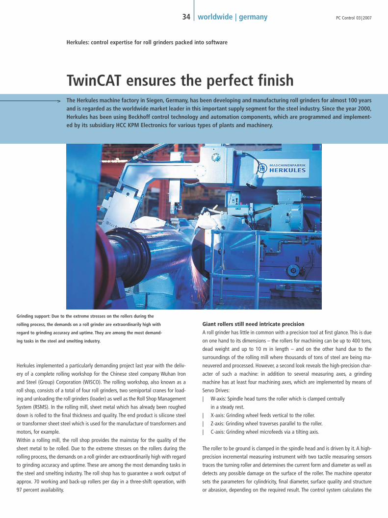
Herkules implemented a particularly demanding project last year with the deliv-
ery of a complete rolling workshop for the Chinese steel company Wuhan Iron
and Steel (Group) Corporation (WISCO). The rolling workshop, also known as a
roll shop, consists of a total of four roll grinders, two semiportal cranes for load-
ing and unloading the roll grinders (loader) as well as the Roll Shop Management
System (RSMS). In the rolling mill, sheet metal which has already been roughed
down is rolled to the final thickness and quality. The end product is silicone steel
or transformer sheet steel which is used for the manufacture of transformers and
motors, for example.
Within a rolling mill, the roll shop provides the mainstay for the quality of the
sheet metal to be rolled. Due to the extreme stresses on the rollers during the
rolling process, the demands on a roll grinder are extraordinarily high with regard
to grinding accuracy and uptime. These are among the most demanding tasks in
the steel and smelting industry. The roll shop has to guarantee a work output of
approx. 70 working and back-up rollers per day in a three-shift operation, with
97 percent availability.
Giant rollers still need intricate precisionA roll grinder has little in common with a precision tool at first glance. This is due
on one hand to its dimensions – the rollers for machining can be up to 400 tons,
dead weight and up to 10 m in length – and on the other hand due to the
surroundings of the rolling mill where thousands of tons of steel are being ma-
neuvered and processed. However, a second look reveals the high-precision char-
acter of such a machine: in addition to several measuring axes, a grinding
machine has at least four machining axes, which are implemented by means of
Servo Drives:
| W-axis: Spindle head turns the roller which is clamped centrally
in a steady rest.
| X-axis: Grinding wheel feeds vertical to the roller.
| Z-axis: Grinding wheel traverses parallel to the roller.
| C-axis: Grinding wheel microfeeds via a tilting axis.
The roller to be ground is clamped in the spindle head and is driven by it. A high-
precision incremental measuring instrument with two tactile measuring sensors
traces the turning roller and determines the current form and diameter as well as
detects any possible damage on the surface of the roller. The machine operator
sets the parameters for cylindricity, final diameter, surface quality and structure
or abrasion, depending on the required result. The control system calculates the
The Herkules machine factory in Siegen, Germany, has been developing and manufacturing roll grinders for almost 100 yearsand is regarded as the worldwide market leader in this important supply segment for the steel industry. Since the year 2000,Herkules has been using Beckhoff control technology and automation components, which are programmed and implement-ed by its subsidiary HCC KPM Electronics for various types of plants and machinery.
34 worldwide | germany PC Control 03 | 2007
TwinCAT ensures the perfect finish
Herkules: control expertise for roll grinders packed into software
Grinding support: Due to the extreme stresses on the rollers during the
rolling process, the demands on a roll grinder are extraordinarily high with
regard to grinding accuracy and uptime. They are among the most demand-
ing tasks in the steel and smelting industry.
PCcontrol_3_07_GB_191107.qxd 19.11.2007 14:32 Uhr Seite 34

grinding process from these parameters. Continuous measuring is carried out si-
multaneously in order to record the results of the grinding process and determine
or correct the required values for the next travel.
Certain manufacturing processes in the steel and paper industries require a pre-
cisely defined roller form. These can be conical or spherical or – looked at from
the longitudinal axis – display a sinusoidal or bottleneck form (CVC). These vari-
ations of form are not visible to the naked eye, as they are on the order of mil-
limeters. The automotive industry, for example, has specific requirements for the
surface structure of the sheet metal in order to have shine and reflective proper-
ties in the sprayed bodywork, which could not be achieved by spraying alone. The
necessary grinding precision goes down to 1/1000 mm in concentricity and the
same in geometrical accuracy.
In order to do justice to this complex task, HCC KPM Electronics has produced a
control system which can be applied with only minor adaptations to all kinds of
machines – all on the PLC and Motion Control solution, TwinCAT PTP and
NC I/CNC software.
35 worldwide | germanyPC Control 03 | 2007
HCC KPM measurement and inspection system
“on the fly”. The high precision, incremental
measuring instrument with two tactile measur-
ing probes travels along the rotating roller and
determines its current shape and diameter as
well as any damage to the surface of the roller.
Herkules roll grinder type WS 450 L MonolitTM
PCcontrol_3_07_GB_191107.qxd 19.11.2007 14:32 Uhr Seite 35

Synergy from customer expertise and an intelligent control conceptIn order to utilize the benefits of a central control concept in terms of commis-
sioning, maintenance and performance, the electrical design engineers at
Herkules aimed to run as many functions as possible in software and decided in
favor of TwinCAT. The open software structure and the dynamic functions for con-
trolling axis movement that TwinCAT provides enabled Herkules to integrate the
expertise acquired over many years of developing their own control system into
the software PLC and create the “HCC/KPM 10” roll grinder control system.
Almost all the functionalities provided by TwinCAT are used:
| 3 PLC tasks in one run-time system with 1 or 10 ms interval time
| 1 NC task with up to 10 axes with 2 ms interval time
| almost all programming languages (IL, FBD, ST, SFC) in the PLC projects
| application of PTP axis functions and complex multi-table coupling for the
grinding processes with correction parameters from the grinding current,
grinding wheel wear and measured deviations from the required form to
the actual form of the roller
| communication with integrated visualization based on Visual Basic and
operating guidance through the ADS DLL communication interfaces
| TwinCAT NC I for interpolating functions e.g. to mill concentric grooves
in the surface of the roller
Lightbus is used as the fieldbus to incorporate the peripheral Beckhoff Bus Ter-
minals within the machine. For communication with the Servo Drives, the Ether-
net-based EtherCAT bus system is predominantly used. A major benefit of
EtherCAT on one hand is its real-time capability and high data throughput – with
bus cycle times of less than 1 ms – and, on the other, simple handling using
TwinCAT. Only one free network port is necessary in the control PC. The Servo
Drives are connected via standard network cables.
Transport tasks controlled by softwareThe large-scale WISCO project offers not only four roll grinders, but also includes
two automatic semiportal cranes for loading and unloading the roll grinder
(Loader). The Roll Shop Management System RSMS manages the grinding tasks
and the rollers – another core competency of the Herkules Group. The software
plans the production process and allocates the transport tasks to the loader or
the machining tasks to the grinding machines. The loader transports the rollers to
be machined to the grinding machines and the finished rollers back to the stor-
age locations. TwinCAT NC I running on the control PC of the loader takes care of
the transport and the exact positioning of the rollers in the infeed of the grind-
ing machines.The transport of the rollers into or out of the automated zone is car-
ried out by an overhead crane.
TwinSAFE guarantees safety of personnelThe automated zone, in which the grinding machines and loader operate, is di-
vided into different safety areas. Security doors with guard locking prevent peo-
ple entering the danger zone. All security-related signal preprocessing and con-
trol is implemented using the Beckhoff TwinSAFE system.
The status of the following is monitored:
| 9 security doors
| 6 light barriers
| 14 emergency stop keys
| 2 laser scanners (protection for loaders from collision with each other)
| 8 laser scanners using secure radio (protection from collision for the loader
with the overhead cranes)
| safety relay for the drives (safety circuit breaker for drives)
| 12 key switches (bridging options, number of operating modes)
Control Panel with customized designThe input to the machine is made via a Control Panel, which was de-
signed and planned jointly with Herkules in line with their particular
needs. All hardware operating elements integrated in the panel are
linked to the control PC via Lightbus. This compact and highly integrated
operating design enables stationary machine management and the im-
plementation of the mobile support control station. The HCC Graphical
User Interface (GUI), with which the operator adjusts and operates the
complex machine, is visualized on the panel. The operator obtains all the
information about the roller and the current grinding status via the GUI.
The link from TwinCAT to the multilingual GUI takes place via ADS-DLL,
the versatile communication interface from Beckhoff.
36 worldwide | germany PC Control 03 | 2007
Herkules roll grinder type WS 600. The rollers to be
machined can weigh up to 400 tons and measure up
to 10 meters in length.
Inputs to the machine are made
via a Control Panel that was de-
signed in cooperation with
Herkules in accordance to their
special requirements.
PCcontrol_3_07_GB_191107.qxd 19.11.2007 14:32 Uhr Seite 36

Additional functionalities
| release for the 9 security doors
| detection and monitoring of the loader position
(in relation to safety zones)
| establishing the emergency stop connection with the (4) grinding machines
(dependent on the position of the loader)
| controlling the safety relay of the drives
TwinSAFE safety technology includes checking of the emergency stop keys and
the emergency stop requirement for the machines and relays these to the load-
ing installations. In addition, the status of the safety zones is monitored and – de-
pendent on status – a decision is made as to whether the loading installation is
allowed to drive into the zone. Release of the security doors using TwinSAFE out-
puts depends on the positions and operation modes of the loader. The operation
modes can also be selected via key switches if desired: in MANUAL, a secure ra-
dio remote control with an additional emergency stop is connected.
The status of the drives is also monitored with TwinSAFE. The merged emergency
stop signals to the loader can stop the drives via the secure bus terminal outputs.
The signals from the loaders’ collision monitoring and those from the loader with
37 worldwide | germanyPC Control 03 | 2007
The roll shop for the Wuhan Iron and Steel Group is made upof the following components:| 3 roll grinders Type “WS 450-6 x 5000 CNC MonolithTM“ for grind-
ing work rollers and intermediate rollers
| 1 roll grinder Type “WS 600 x 5000 CNC MonolothTM” for grinding
work rollers, intermediate rollers and back-up rollers
| 2 automatic semiportal cranes (loader) for transporting the rollers
from or to the machines
| 1 Roll Shop Management System (RSMS) for managing the roller
and storage data as well as for controlling the production process
Beckhoff components used:| 8 control cabinet Industrial PCs C5102-0010
| 4 Control Panels CP7832-1050
| 24 Lightbus Bus Couplers BK2000/BK2020
| 12 EtherCAT Bus Couplers BK1120
| approx. 1,100 Bus Terminals
| Bus systems used:
– Lightbus
– PROFIBUS
– EtherCAT
– Real-time Ethernet
Herkules roll grinder WS 450
MonolitTM for grinding work
and intermediate rollers
the overhead cranes lead to an emergency stop.
In order to implement these safety functions, a total of 19 TwinSAFE Logic Bus
Terminals and 51 secure KL1904 input terminals were integrated in a safety net-
work. All safety functions are implemented in two channels.
The TwinSAFE signals are integrated in the grinding machines via Lightbus, the
individual Logic Terminals communicate with one another via real-time Ethernet
using network variables. In total, this results in an average of six communication
connections per machine control system to the I/O level, the servo converter, the
central control, the RSMS and the loader. In this design PROFIBUS, via which an
ultrasound crack testing system is networked, functions like “the odd fieldbus
out.”
"This is where the exceptional character of the TwinCAT controller is so impres-
sive, in that it deals with both the PLC and NC functionalities in real time and al-
lows a diverse range of fieldbuses to communicate faultlessly," observed HCC
software engineer Oliver Kettner who has been responsible for commissioning the
plant. The control and automation concept described here has been implement-
ed with custom modifications in approx. 250 machines so far.
Herkules www.herkules-group.de
PCcontrol_3_07_GB_191107.qxd 19.11.2007 14:33 Uhr Seite 37

The flawless rotation of a wheel is the most fundamental requirement for safe
and comfortable travel. Wheel gauging systems serve to guarantee this require-
ment. They measure the geometrical features of the wheel, such as radial and ax-
ial runout, circumference, width, center hole diameter and its centricity. Some di-
mensions can be measured directly, while others can only be derived from a com-
bination of measured dimensions. Wheel gauging systems have to operate with
utmost precision and be accurately reproducible and highly productive.
IEF Werner has met this challenge with fully automatic wheel and rim gauging
machines of various types. They have been successfully implemented in full-scale
production in the automotive industry for over 20 years. The modular construc-
tion of the mechanics, electronics and control software in particular permit a sys-
tem that can be configured easily according to precise customer needs. Important
functions such as recording dimensions and calculation as well as the display of
measurement results are likewise provided on an individual basis.
38 worldwide | germany PC Control 03 | 2007
Wheel gauging systems are the measure of success
Highly-precise, repeatable measurement with TwinCAT automation software
Wheel gauging machine R2010The modular construction of the R2010 wheel gauging machine for car and truck
wheels integrates the latest advances from the fields of information technology,
optics, laser technology and micro technology.The basic frame of the wheel gaug-
ing machine, a torsion-resistant machine body made from thermally and vibra-
tion-resistant polymer concrete, creates the basis for high-precision measuring.
The rotating and clamping unit, being the support for the wheels or rims, is the
reference point for all measurements. The wheel gauging machine can be
equipped with up to three measuring stations each with two measuring heads.
Each measuring head contains up to three freely programmable axes. Linear
drives combined with innovative drive technology operate the measuring heads
with precision and accurate repeatability.
Precise and highly accurate measuring sequencesIEF Werner chose PC-based control technology from Beckhoff to control the com-
plex measuring sequences. Harald Lorenz, IEF product manager for wheel gaug-
ing systems, stresses: “We selected the Beckhoff system because it offered us the
best option for integrating the sequential control for a machine with the complex
functions of technically/scientifically applied software in one computer, without
loss of performance. This was confirmed on a prototype on which we were even
able to increase the performance in relation to cycle times, visual representation
of complex sequences and network connections.” The core of the control system
is the control cabinet Industrial PC C6350 with the operating system Windows XP
Thanks to leading edge control technology from Beckhoff, wheel gauging systems made by IEF Werner GmbH are able torecord the geometrical features of wheels of every kind (cars, trucks, tractors) with high precision in an exactly reproducible way. Even dimen-sions with minimal tolerances can be measured precisely and reliably. As a result, IEF Werner wheel gauging systems can fulfill the demandingrequirements of the automotive industry.
PC-based control system for wheel gauging machine R2010 made by IEF Werner GmbH
PCcontrol_3_07_GB_191107.qxd 19.11.2007 14:33 Uhr Seite 38
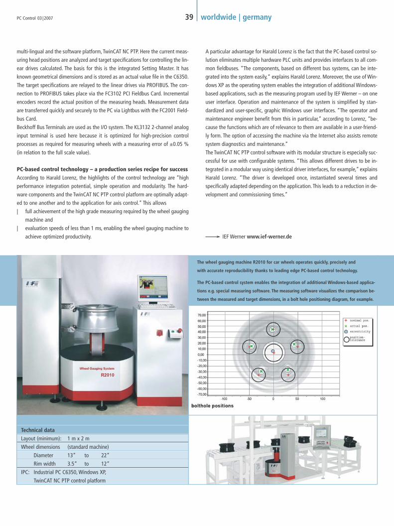
The wheel gauging machine R2010 for car wheels operates quickly, precisely and
with accurate reproducibility thanks to leading edge PC-based control technology.
A particular advantage for Harald Lorenz is the fact that the PC-based control so-
lution eliminates multiple hardware PLC units and provides interfaces to all com-
mon fieldbuses. “The components, based on different bus systems, can be inte-
grated into the system easily,“ explains Harald Lorenz. Moreover, the use of Win-
dows XP as the operating system enables the integration of additional Windows-
based applications, such as the measuring program used by IEF Werner – on one
user interface. Operation and maintenance of the system is simplified by stan-
dardized and user-specific, graphic Windows user interfaces. “The operator and
maintenance engineer benefit from this in particular,” according to Lorenz, “be-
cause the functions which are of relevance to them are available in a user-friend-
ly form. The option of accessing the machine via the Internet also assists remote
system diagnostics and maintenance.”
The TwinCAT NC PTP control software with its modular structure is especially suc-
cessful for use with configurable systems. “This allows different drives to be in-
tegrated in a modular way using identical driver interfaces, for example,” explains
Harald Lorenz. “The driver is developed once, instantiated several times and
specifically adapted depending on the application. This leads to a reduction in de-
velopment and commissioning times.”
IEF Werner www.ief-werner.de
39 worldwide | germanyPC Control 03 | 2007
multi-lingual and the software platform, TwinCAT NC PTP. Here the current meas-
uring head positions are analyzed and target specifications for controlling the lin-
ear drives calculated. The basis for this is the integrated Setting Master. It has
known geometrical dimensions and is stored as an actual value file in the C6350.
The target specifications are relayed to the linear drives via PROFIBUS. The con-
nection to PROFIBUS takes place via the FC3102 PCI Fieldbus Card. Incremental
encoders record the actual position of the measuring heads. Measurement data
are transferred quickly and securely to the PC via Lightbus with the FC2001 Field-
bus Card.
Beckhoff Bus Terminals are used as the I/O system. The KL3132 2-channel analog
input terminal is used here because it is optimized for high-precision control
processes as required for measuring wheels with a measuring error of ±0.05 %
(in relation to the full scale value).
PC-based control technology – a production series recipe for successAccording to Harald Lorenz, the highlights of the control technology are “high
performance integration potential, simple operation and modularity. The hard-
ware components and the TwinCAT NC PTP control platform are optimally adapt-
ed to one another and to the application for axis control.” This allows
| full achievement of the high grade measuring required by the wheel gauging
machine and
| evaluation speeds of less than 1 ms, enabling the wheel gauging machine to
achieve optimized productivity.
The PC-based control system enables the integration of additional Windows-based applica-
tions e.g. special measuring software. The measuring software visualizes the comparison be-
tween the measured and target dimensions, in a bolt hole positioning diagram, for example.
Technical data
Layout (minimum): 1 m x 2 m
Wheel dimensions (standard machine)
Diameter 13” to 22”
Rim width 3.5“ to 12“
IPC: Industrial PC C6350, Windows XP,
TwinCAT NC PTP control platform
PCcontrol_3_07_GB_191107.qxd 19.11.2007 14:34 Uhr Seite 39

A Georgian building from the 1800s presented a challenge with numerous offices,
workshops, studios and meeting places to be connected wirelessly – all with no
maintenance, at low cost, and with a requirement where the installation and
breakdown of the exhibition did not disrupt daily operations within the building.
The entire Architectural Association building was modeled on a scale of 1:6 to fit
into the exhibition space. The building was represented in space purely by the ac-
tual light sources present in the building itself.
Alex Haw decided to use EnOcean radio technology for realizing his light show.
Each of the 160 cellular zones of the building is laced with a range of EnOcean
sensors including door contacts, seat sensors, repeaters, pushbuttons, infrared de-
tectors and IP cameras that monitor all movements inside the building.
The EnOcean sensors feed information to nodal receivers (KL6023 wireless
adapters) located around the building, and then into a Beckhoff BC9000 Ether-
net controller. The wireless adapters receive the signals from the EnOcean sensors
and convert them to an RS485 signal that is directly processed further by
KL6021-0023 serial Bus Terminals. The system is programmed via TwinCAT PLC.
Communication with the Digital Multiplex (DMX) control system was also imple-
mented with the aid of TwinCAT. DMX is a digital control protocol that is used in
stage and show applications for controlling dimmers, intelligent spotlights and
effect devices and is based on RS485.
LightHive is a unique light show that mimics all movements and processes within a building through light. It isa gigantic 'lighthouse', signaling the activity of the Architectural Association building in Bedford square, Londonthrough its windows to the world beyond. LightHive was realized by architect Alex Haw using EnOcean radiotechnology and control technology from Beckhoff.
40 worldwide | great britain PC Control 03 | 2007
Light show or light reality?
LightHive exhibition in London uses Beckhoff I/O system and EnOcean radio technology
The geometry of the original sur-
roundings is represented by 2,054
unique shapes that are customized,
scripted and then laser-cut especially
for the show.
PCcontrol_3_07_GB_191107.qxd 19.11.2007 14:35 Uhr Seite 40

The Beckhoff control system enables transfer of the EnOcean signals to the DMX
controller, which in turn activates the LEDs representing the movement patterns
within the building in the exhibition. “The decision to use the control solution
from Beckhoff was primarily based on the complete openness and simple pro-
gramming of the system. Of special significance was the integration of EnOcean
technology into the Beckhoff system”, said Stephen Hayes, managing director of
Hayes Control Systems, Beckhoff partner in Great Britain.
The final result is impressive: The activity in any room of the building activates
one, or a cluster, of the 1,027 previously mentioned LEDs, bringing light to the
room in a dance of motion, mirroring the patterns of human movement.The space
operates like a 3-D X-ray of the building's activity – a kind of constantly updat-
ing surround-light CCTV, a spatial model of the entire Architectural Association's
activities fluctuating over the course of hours, days and weeks.
Hayes Control Systems Ltd www.hayescontrols.co.uk
41 worldwide | great britainPC Control 03 | 2007
The LightHive exhibition is controlled by a BC9000 Bus
Terminal Controller. The EnOcean signals are processed
via a KL6023 EnOcean adapter and KL6021-0023 serial
Bus Terminals. TwinCAT PLC was used for programming.
PCcontrol_3_07_GB_191107.qxd 19.11.2007 14:36 Uhr Seite 41

The core business of Huhtamaki Molded Fiber Technology in Franeker, in the Dutch
province of Friesland, involves the production of egg boxes made from pressed
paper. The current packaging hits are the futuristically designed and colored
@ttract! egg boxes, for which Huhtamaki also builds the necessary production
machines.
In order to manufacture the egg boxes, wet paper fibers are pressed into a spe-
cific mold – hence the name ‘molded fiber’. The paper pulp is initially layered in
a mold that has small air holes on the inner sides. The paper is drawn into the
mold by means of vacuum and a press is subsequently applied. After that, the
product is dried, briefly moistened again and pressed a second time. Jelle Post,
Technology & Development Manager of the Engineering Department at Huhta-
maki, explains: “The egg box gets its smooth surface from this wet treatment.
Besides the luminous colors, the stylish features that distinguish the new @ttract!
series from the conventional grey egg packaging are the rounded edges and the
3-D labeling technology, which allows the box to be printed on all sides.”
Machine construction nicheIn constructing this special machine for the production of @ttract! egg boxes,
Huhtamaki is occupying a niche position that is becoming typical in the packag-
ing market. The company has founded its own machine construction company un-
der the name Huhtamaki Molded Fiber Technology (HMFT) BV, which supplies
Leotech machines and process technologies. “Here in Franeker, we are continual-
ly developing new techniques for Huhtamaki’s worldwide molded fiber business,”
says Post, “to best enable the manufacturing of new packaging products.”
Packaging machines are sometimes so custom to the application that the packaging manufacturer prefers to build them in-house. With these conditions in mind, Huhtamaki, whose head office is in Finland, is not only one of the largest manufacturers of packaging inthe world, they also build the matching machines. Huhtamaki uses Beckhoff Industrial PCs and EtherCAT as the control platform in the machinefor manufacturing colored egg boxes. On account of the positive experience, Beckhoff controllers have been declared the in-house standard.
42 worldwide | netherlands PC Control 03 | 2007
PC Control and EtherCAT for premium packaging
“@ttract”-ive egg boxes from Huhtamaki
PCcontrol_3_07_GB_191107.qxd 19.11.2007 14:36 Uhr Seite 42

Technical innovation makes new design possible“On account of the speed, precision and flexibility required for the production
machines in the @ttract! series, we could no longer work with traditional PLCs
and therefore decided to switch to Servo Drives and Industrial PCs,” explains Post.
“Since we do not employ any control specialists ourselves, we set off in search of
a partner who could take care of the control technology part. Our choice fell on
Kremer Industriële Automatisering BV and Beckhoff,” says the engineering
expert.
The servo technology now enables faster and more precise control and, in addi-
tion, simpler construction of the presses, where the main concern is to ensure that
the spindles, which are electronically linked to one another, are driven synchro-
nously. “Using the Servo Drives and the Beckhoff Industrial PC, we can now guar-
antee synchronous running of the spindles with a maximum deviation of the mo-
tor axis of 1.8°, irrespective of the load. Previously, with regard to precision, we
consciously went to the limit, so we have switched from Lightbus and SERCOS to
EtherCAT for the fieldbus communication,” says Post, summarizing the advan-
tages of the new controller.
Another important component of the production line is the labeling unit, which
represents a new development. The label is affixed to the strongly-arched box
using a special adhesive. Labeling takes place at very high speed. Beckhoff
provides a premium service here too: a minute shift of 0.5 mm can be controlled
in just 1 ms.
Kremer Industriële Automatisering BV from
‘s-Heerenberg has been a Beckhoff system
integrator right from the start. The company
not only has outstanding knowledge of pro-
duction processes and controllers, but also
understands how to combine them with the
Beckhoff PC-based control concept. Kremer
works for Huhtamaki as a technology part-
ner, supporting the development of new
machines and the modernization of existing
ones.
43 worldwide | netherlandsPC Control 03 | 2007
Advantages of the Industrial PCThe use of Industrial PCs offers great flexibility and makes modular expansion of
the controller possible. Jelle Post adds: “Besides that, the Industrial PC is inte-
grated in the factory network. All relevant data is saved in an SQL database via
Ethernet. A VPN connection can be established for maintenance work so that we
can carry out remote servicing.”
On account of the positive experiences in the past few years, Huhtamaki has
made the Beckhoff control system the standard for their various machine types.
The C6140 control cabinet PC from Beckhoff is used for the larger machines
(presses and the all-side labeling unit). Various fieldbuses are used for the
connection between the Industrial PC and the Servo Drives, including Lightbus,
SERCOS and CANopen. EtherCAT is used in the newest machines. Smaller ma-
chines, such as printer lines and denesters are controlled by the DIN rail-mount-
ed CX1020 Embedded PC running Windows CE. These systems are visualized by
means of a .NET application.
Huhtamaki Molded Fiber Technology B.V. www.huhtamaki.nl
Kremer Industriële Automatisering BV www.kremer.nl
Industrial Automation Link www.ial.nl
The ultra fast EtherCAT fieldbus makes
the desired specifications possible.
For the production of the new @ttract!
egg carton series, Huhtamaki has built,
among other items, a new press based
on Beckhoff servo technology and
Industrial PCs.
PCcontrol_3_07_GB_191107.qxd 19.11.2007 14:36 Uhr Seite 43

Ambitious transportation infrastructure projects such as the 24.5 km (15 mile) long “Túnel de Pajares” built for the AVE high-speedtrain in northern Spain, can be constructed today in a relatively short time due to impressive advances in boring technology. The com-pany responsible for the construction, Acciona S. A. with its headquarters in Alconbendas near Madrid, decided to utilize the BeckhoffI/O system when equipping their tunnel boring machine, because its robust design can address extremely high environmental demandsfor resistance against dust, humidity and strong vibration and in addition can be installed in a very compact space.
44 worldwide | spain PC Control 03 | 2007
Tunneling through mountains using Beckhoff technology
Robust and compact I/O components for tunnel construction
Modern tunnel boring machines are
large-scale machines with diameters
of 10 meters and above.
PCcontrol_3_07_GB_191107.qxd 19.11.2007 14:36 Uhr Seite 44

Construction of the 24.5 km (15 mile) long
“Túnel de Pajares” for the Spanish AVE high-
speed train was completed within only two
years using the most advanced tunnel boring
technology.
Whether underground, underwater or deep in a mountain, and whether the
tunnel is for a road, rail, metro, supply or waste – advanced boring technolo-
gies help create vital connections and essential infrastructure for the eco-
nomic development of industrialized countries.Tunnel boring machines (TBM)
with a diameter of up to 10 meters and above can handle entire sections of
tunnel and, if needed, can secure the excavation site with a provisional or fi-
nal lining at the same time.
Tunnel construction with advanced technologyWorking the rock or layers of earth is usually done by a revolving drill head
with cutting edges, powered by hydraulic motors which in turn are supplied
by electric motors, as the machine is usually powered by electricity. The sup-
ply units for the tunnel boring machine are behind the drill head: a row of
platforms follow the boring head on metal rails which themselves have been
laid down by the machine. On these platforms are the tanks, power supply,
ventilation, material silos and the conveyor system for the excavated material.
Needless to say on these kinds of large machines, there are hundreds of sen-
sors and detectors which all securely transfer information to the control cen-
ter, so that the boring machine operator can carry out the various control and
monitoring tasks.
Decentralized I/Os save installation time during assembly and disassemblyThe tunnel boring machines are set up, disassembled and transported to an-
other site after the work is completed. This is the reason that the use of de-
centralized I/Os saves a large amount of money in the form of less installa-
tion time. It makes a difference whether hundreds of cables have to be con-
nected or disconnected, or if there is only a single communication cable. In
addition, mistakes when connecting the equipment are largely avoided,
which leads to impressive time savings during commissioning.
For this project,Acciona decided to replace most of the sensor wiring with de-
centralized bus terminal stations with PROFIBUS networking. These nodes
transmit the data from the PT100 temperature sensors as well as the digital
and analog I/Os to the control room.
Exceptionally robust and compact designOne of the greatest challenges for Beckhoff technology in this application is
the extremely difficult operating conditions for the equipment, such as dust,
humidity, strong vibrations, etc. In view of the very limited space available,
the I/O system had to have exceedingly compact dimensions – an important
criteria for Acciona in deciding in favor of high density KM I/O modules from
Beckhoff. These terminal modules complement the Beckhoff I/O system with
an extremely compact terminal design and increased packing density. The KM
terminal modules combine 16, 32 or 64 digital inputs or outputs on a very
compact area.
Francisco Gorines, maintenance manager at Acciona, explains this point:
“One of the reasons that we decided to go for the Beckhoff technology was
the small dimensions of the system and the large supply of I/Os. There are
many different pieces of equipment integrated in our system, such as PT100,
4...20 mA, 0...10 V, etc. and we know that Beckhoff Bus Terminals provide for
all these types of devices.”
Accionia S.A. www.acciona.es
Beckhoff Spain www.beckhoff.es
45 worldwide | spainPC Control 03 | 2007
logyDue to the very limited space available,
an I/O system was needed that can be
installed in a very compact space.
Francisco Gorines, maintenance manager
at Acciona, explains the decision to use
the Beckhoff I/O components: “One of
the reasons that we decided to go for the
Beckhoff technology was the small dimensions
of the system and the large supply of I/Os.”
The tunnel boring machine is only halted for mainte-
nance purposes. It operates round the clock.
One of the decisive reasons that Acciona decided in favor of
Beckhoff I/O technology was resistance to the extremely harsh
operating conditions such as dust, humidity and strong vibrations.
PCcontrol_3_07_GB_191107.qxd 19.11.2007 14:37 Uhr Seite 45

The Proventia Group concentrates its research and devel-
opment work on automated production lines in the elec-
tronics, metalworking and composites industries using
versatile robots that help increase efficiency. In addition,
Proventia deals with robot milling and grinding for the
yacht and boat industry, particularly in connection with
composites and reinforced plastics. Proventia's robots are
also used for grinding and finishing aircraft turbines.
“Our robot systems have several benefits. On the one
hand, they are extremely versatile and on the other, the
in-house developed software for programming allows a
variety of movements. Being equipped with at least sev-
en axes, the Proventia robots have a high capacity and
flexible range of operation,” explained Mika Laitinen,
technical director of Proventia.
46 worldwide | finland PC Control 03 | 2007
EtherCAT-based robot control
Proventia assembly system is the answer for the mobile telephone industry
The CIRB500i is a very versatile robotic
cell that can cover a wide range of
tasks in the high-volume electronics
industry thanks to its modular struc-
ture. Control of the robotic cell is car-
ried out using TwinCAT NC PTP.
Since the merger of the Finnish Master Automation Group with specialists in robot systems, Proventia, the newly formed'Proventia Production Technologies' is hoping for a growth spurt. The company has got its eye on the electronics industry and mobile tele-phone manufacturing in particular. As Proventia explained, equipping robot systems with PC-based control technology from Beckhoff givesthe company a positive competitive advantage.
O
c
Ap
– h
e
– a
– a
– a
– p
– t
– q
Fea
– f
– I
– 4
– c
Op
– p
– 6
– v
– s
p
– T
i
w
PCcontrol_3_07_GB_191107.qxd 19.11.2007 14:37 Uhr Seite 46

47 worldwide | finlandPC Control 03 | 2007
Mika Laitinen, technical director at
Proventia, is pleased with the benefits
of EtherCAT-based automation:
“EtherCAT enables the achievement of
shorter response times, which is a deci-
sive advantage for robot control.”
Windows as technology platformIn 2006, the former Master Automation Group launched
the robotic cell CIRB500i for the electronics industry on-
to the market, which immediately evoked a great deal of
interest, especially in the mobile telephone industry. The
CIRB500i is a very versatile robotic cell that covers a wide
range of tasks in the high-volume electronics industry
thanks to its modular structure. They can be used for fit-
ting small parts as well as for handling, packing, check-
ing and inspection of standard parts.
“In the course of calling for vendors, Beckhoff was se-
lected as the supplier of control and drive technology. The
robotic cell control takes place via the PLC and Motion
Control software TwinCAT NC PTP and the CX1020 Em-
bedded PC. Servo drives from the AX2000 range are used
for the drive technology. A higher-level, built-in Panel PC
CP6500 functions as the HMI and features a customized
design – especially made for Proventia. The CP6500
communicates with the CX1020 motion controller using
TwinCAT ADS,” explained Aki Kalajainen, regional sales
manager for Beckhoff Finland.
“We chose Beckhoff because, among other things, the
product range covers linear servomotor technology. Two
of the four axes in the robotic cell are rapid linear servo-
motors. In addition, we were looking for a control system
that could be easily integrated into a Windows environ-
ment. Universal interfaces were required to which we
could connect our own software packages,” Laitinen ex-
plained Proventia's requirements.
Proventia chose EtherCAT as the system’s fieldbus. “Us-
ing EtherCAT, we can achieve shorter response times,
which is a decisive advantage in robot control,” accord-
ing to Laitinen.
Proventia Production Technologies
www.proventia.fi
Beckhoff Finland www.beckhoff.fi
The built-in Panel PC CP6500 serves as the HMI and features a customized look and feel. A CX1020 Embedded
PC is responsible for controlling the robotic cell. Communication between the central control system and the
robotic cell is carried out using Ethernet; the connection to the servomotors is implemented via EtherCAT.
Overview of the assembly
cell CIRB500i
Applications
– high-volume production of
electronics items
– attaching small parts
– attaching labels and logos
– assembly
– packing, unpacking
– testing
– quality control
Features
– fast, linear technology
– Industrial PC with touch screen display
– 4-camera vision system
– conveyor belt
Options
– pallet or flat-belt conveyor
– 6-axis manipulator
– various feeding options
– simple adjustment to changes in the
production flow
– The individual cells can be combined
into a complete production line in a
wide range of ways.
PCcontrol_3_07_GB_191107.qxd 19.11.2007 20:33 Uhr Seite 47

SPS/IPC/DRIVES 2007
This simple formula represents the essence of the
EtherCAT Technology Group booth at SPS/IPC/
DRIVES, where 50 manufacturers will display more
than 100 EtherCAT products including sensors, I/O
components, drives, hydraulic and pneumatic valves,
and controllers with a wide range of performance
options. Speaking of controllers: The diversity of
EtherCAT masters for different operating systems is
no doubt a unique selling point of EtherCAT that
clearly illustrates the openness of the technology in
practice. At the ETG booth visitors can see 20 differ-
ent controllers running on 10 operating systems. The
range of drive suppliers is also expanding continu-
ously: At SPS/IPC/DRIVES companies such as Lenze,
Emerson Control Techniques, Bosch Rexroth and oth-
ers will show drives with EtherCAT interfaces for the
first time. Not long ago Hitachi already showed asso-
ciated products on the ETG booth at the System
Controls Fair in Tokyo.
48 ETG PC Control 03 | 2007
Hall 7, Booth 309
Powerful technology + simple implementation = wide variety of products
PCcontrol_3_07_GB_191107.qxd 19.11.2007 14:38 Uhr Seite 48

This is the positive result of more than 4 years of IEC committee work, during
which the EtherCAT Technology Group was declared an official IEC standardiza-
tion partner. As early as 2005 the EtherCAT specification was published by IEC as
IEC/PAS 62407, which is now being replaced by the International Standards.
In IEC 61158, the EtherCAT protocols and services are standardized, while
IEC 61784-2 defines profiles for specific device classes.
IEC 61800-7 is particularly important for Motion Control applications, since it
makes EtherCAT a standardized communication technology for the SERCOS and
CANopen drive profiles, on an equal footing with SERCOS I-III and CANopen re-
spectively. The drive parameters and state machines as well as the process data
layout of the device profiles remain untouched when mapped to EtherCAT. Hence
the user interface does not change when moving from SERCOS and CANopen
to EtherCAT, and device manufacturers can re-use major parts of their firmware.
“The international standardization that was now completed successfully is an im-
portant milestone for EtherCAT. It help us machine builders to further increase the
acceptance of this superior technology in particular with our key-account cus-
tomers. The device vendors get a complete specification which was written ac-
cording to international rules,” comments Erich Hutflesz, ETG board member and
manager of control systems at Schuler.
The EtherCAT Technology Group continues to actively participate in IEC stan-
dardization. Currently Safety over EtherCAT is introduced to the appropriate work
groups in order to include it into the next revision of IEC 61784-3, which is sched-
uled for 2009.
49 ETGPC Control 03 | 2007
EtherCAT as communication technology for SERCOS and
CANopen drive profiles now International Standard
The IEC standards 61158, 61784-2 and 61800-7 have passed the final voting unanimously:Thus EtherCAT now is an official IEC standard.
EtherCAT is already used in many semiconductor and flat panel display
manufacturing applications. The world’s largest supplier of semiconduc-
tor manufacturing equipment, Applied Materials, was among the first
EtherCAT Technology Group members back in 2003. EtherCAT was offi-
cially introduced to the industry at a SEMI congress in 2004. A year
later, Samsung Electronics developed the first EtherCAT device for the
ultra high resolution hybrid stage control. Many other manufacturers
from this field have joined the EtherCAT Technology Group: About 100
of the now 590 member companies are particularly active in semicon-
ductor manufacturing.
The North American SEMI Information & Control Committee accepted
the EtherCAT standard, which will be published as SEMI E54.20 in Octo-
ber. This milestone will further accelerate the acceptance of EtherCAT
within the semiconductor and flat panel display manufacturing
industries.
“The superior performance, bandwidth and topology flexibility of
EtherCAT allows to cover the entire range of communication require-
ments in semiconductor manufacturing equipment with just one tech-
nology: from process control via control computer integration to high-
end Motion Control applications. Thanks to fully integrated fieldbus
gateways, special devices, which may not yet be available with
EtherCAT interface, can be integrated seamlessly and cost efficiently.
The semiconductor industry appreciates this EtherCAT feature, since it
supports simple migration. We are proud that EtherCAT has such an
impact on this key industry,” comments Martin Rostan, Executive Direc-
tor of the EtherCAT Technology Group.
EtherCAT approved by SEMI
SEMI (Semiconductor Equipment and Materials International) has approved EtherCAT for their applications by accepting the EtherCAT SEMI standard. The leading standards organization thus responds to the growing interest of the industry in the fastest Industrial Ethernet solution.
PCcontrol_3_07_GB_191107.qxd 19.11.2007 14:39 Uhr Seite 49

PC Control 03 | 2007
Trade shows 2008
Europe
Germany
Tire Technology Expo
February 19 – 21, 2008
Cologne
Booth 6735
www.tiretechnology-expo.com
embedded world
February 26 – 28, 2008
Nuremberg
Hall 9, Booth 329
www.embedded-world.de
intec
February 26 – 29, 2008
Leipzig
Hall 1, Booth E09
www.messe-intec.de
CeBIT
March 04 – 09, 2008
Hanover
www.cebit.com
light + building
April 06 – 11, 2008
Frankfurt
Hall 9.0, Booth D50
www.light-building.de
Hanover Fair
April 21 – 25, 2008
Hanover
www.hannovermesse.de
Interpack
April 24 – 30, 2008
Düsseldorf
Hall 15, Booth D25/E26
www.interpack.com
IFAT
May 05 – 09, 2008
Munich
Hall A1, Booth 220
www.ifat.de
AUTOMATICA
June 10 – 13, 2008
Munich
www.automatica-muenchen.de
Motek
September 22 – 25, 2008
Stuttgart
www.motek-messe.de
EuroBLECH
October 24 – 28, 2008
Hanover
www.euro-blech.de
SPS/IPC/DRIVES
November 25 – 27, 2008
Nuremberg
www.mesago.de/SPS
Switzerland
Hilsa
January 22 – 26, 2008
Basel
Hall 1.1, Booth F29
www.hilsa.ch
Belgium
BUILDINGS OF BELGIUM
May 28 – 29, 2008
Brussels
Booth 1000/1017
www.easyfairs.com
France
Interclima+elec
February 05 – 08, 2008
Paris
www.interclimaelec.com
CFIA
11 – 13, March 2008
Rennes
www.cfiaexpo.com
Italy
Bias
May 27 – 30, 2008
Milan
www.bias.it
Spain
BIEMH
March 03 – 08, 2008
Bilbao
www.bilbaoexhibitioncentre.com
MATELEC
October 28 – November 01, 2008
Madrid
www.ifema.es
Asia
India
Elecrama
January 18 – 21, 2008
Mumbai
Hall 5, Booth H5 Q32
www.elecrama.com
50 events
For additional information on our worldwide subsidiaries’
and partner companies’ trade show schedules
please check: www.beckhoff.com
PCcontrol_3_07_GB_191107.qxd 19.11.2007 14:39 Uhr Seite 50

51 ETGPC-Control 03 | 2007 51 ETG
Editor-in-Chief:Frank Metzner
Editors:Gabriele KerkhoffJessica GawronskiMaik KosubekDr. Ursula FrankPhone: +49 (0)52 46 /9 63 -1 40Fax: +49 (0)52 46 /9 63 -1 [email protected]
Published:Beckhoff Automation GmbHEiserstraße 533415 Verl/GermanyPhone: +49 (0)5246 /963-0Fax: +49 (0)5246 /963 [email protected]
imprint
PC Control – The New Automation Technology Magazine
www.beckhoff.com
www.ethercat.org
www.pc-control.net
Graphic Design: www.a3plus.de
Printed by: Scholz, Germany
Circulation: 22.000
Published:three times per year (German and English)
51 communication
Further information about Beckhoff products and technologies or contactaddresses for our worldwide subsidiaries and partner companies can befoud on the Beckhoff website.All PC Control articles are available online at www.pc-control.net.
PC Control 03 | 2007
Picture Proof:Accionia S.A., Spainfotolia (J. Larsen / fliers.de), GermanyHuhtamaki Molded Fiber Technology B.V., NetherlandsIEF Werner GmbH, GermanyMaschinenfabrik Herkules GmbH & Co. KG, GermanyMesser Cutting & Welding GmbH, Germanypanthermedia (Michael J.), GermanyProventia Production Technologies, FinlandTridonic Atco, UK
PCcontrol_3_07_GB_191107.qxd 19.11.2007 14:40 Uhr Seite 51

PCcontrol_3_07_GB_191107.qxd 19.11.2007 14:40 Uhr Seite 52