12 morgan at centerra - viking controls,...
TRANSCRIPT

12 Morgan At Centerra 12 Morgan Lebanon, NH. February, 2016
HEATING, VENTILATING, AND AIR-CONDITIONING (HVAC) 230000 - 1
SECTION 230000 - HEATING, VENTILATING AND AIR-CONDITIONING (HVAC)
PART 1 - GENERAL
1.1 SECTION INCLUDES
A. Description of HVAC system(s), quality expectations, materials and general requirements.
1.2 SYSTEM(S) DESCRIPTION
A. HVAC systems of this contract shall include:
1. Hot water heating system. 2. Air conditioning systems. 3. Hot water pumps and specialties. 4. Radiant slab heating and specialties. 5. Hot water terminals as specified and/or indicated. 6. Thermal insulation for all systems. 7. Testing and adjusting of all systems. 8. General Conditions of the contract. 9. Ventilation systems. 10. Exhaust systems 11. Control systems and specialties. 12. Secure all required permits.
1.3 RELATED DIVISIONS and SECTIONS
A. DIVISION 00 - Procurement and Contracting Requirements
B. DIVISION 01 - General Requirements
C. DIVISION 07 - Thermal and Moisture Protection
D. DIVISION 21 - Fire Suppression
E. DIVISION 22 - Plumbing
F. DIVISION 25 - Integrated Automation
G. DIVISION 26 - Electrical
1.4 REFERENCES
A. 2009 International Building Code with NH amendments
12 Morgan At Centerra 12 Morgan Lebanon, NH. February, 2016
HEATING, VENTILATING, AND AIR-CONDITIONING (HVAC) 230000 - 2
B. 2009 NFPA 101, Life Safety Code.
C. New Hampshire State Fire Code
D. 2009 NFPA 1, National Fire Code, as adopted and amended by NH State Fire Code
E. 2009 International Plumbing Code with NH amendments
F. 2009 International Mechanical Code with NH amendments
G. 2009 International Energy Conservation Code with NH amendments
H. 2014 NFPA 70, National Electric Code
I. Town of Lebanon, New Hampshire ordinances, rules and regulations
J. Lebanon Fire Department rules and regulations
K. All applicable ASTM Standards
1.5 SUBMITTALS
A. See SECTION 013300 - Submittal Procedures, for submittal procedures.
B. Particular equipment has been scheduled on the drawings to establish a standard. Alternative equipment may be used providing performance and features meet or exceed the specified product, including identified accessories. Contractors are responsible for researching (via web sites) the specified equipment to fully understand construction, physical size, rated performance and other particulars before carrying alternative equipment in their bid to assure “equal” status. Equipment construction and technical data is not explained in great detail throughout this specification as that information is readily available electronically and shall be referenced during the bid process by the contractor.
END OF SECTION 230000

12 Morgan At Centerra 12 Morgan Lebanon, NH. February, 2016
OPERATION AND MAINTENANCE OF HVAC SYSTEMS 230100 - 1
SECTION 230100 - OPERATION AND MAINTENANCE OF HVAC SYSTEMS
PART 1 - GENERAL
1.1 GENERAL CONDITIONS
A. All work of this Division is specifically subject to DIVISION 01 - GENERAL REQUIREMENTS for the entire project, plus General Contractor (G.C.) stipulations.
B. Provide all items, articles, materials, operations, or methods listed, mentioned, scheduled on the drawings and/or specified herein including all labor, materials, equipment and incidentals necessary and required for completion of this contract.
1.2 INTENT
A. The intent of the specifications and drawings is to call for finish work, tested and ready for operation.
B. Any apparatus, appliance, material or service not specified or indicated, but necessary to make the work complete and perfect in all respects and ready for operation shall be provided.
C. The drawings are generally diagrammatic, intended to convey the scope of work and indicate the general arrangement of equipment and piping, plus approximate size and locations of equipment.
1.3 WORKMANSHIP
A. All work shall be executed in the best and most thorough manner under the direction of, and to the satisfaction of, the Owner’s representative.
B. This contractor shall, at all times, keep a competent foreman in charge of the work and shall facilitate inspection of installations by the Owner’s representative.
1.4 RULES, REGULATIONS, PERMITS AND FEES
A. All work shall comply with applicable portions of all state or local laws, ordinances, rules and regulations of local utility companies and fire departments, plus DIVISION 01.
B. Nothing contained in these specifications or indicated on the drawings shall be construed to conflict with applicable portions of any laws, ordinances, rules and regulations.
1. All pressure vessels shall be furnished and installed in strict accordance with the applicable
regulations of the state and the ASME codes and shall be equipped with all appurtenances re-quired by the aforesaid codes.
C. All required permits and fees relative to this Division shall be obtained and paid for by this contractor.

12 Morgan At Centerra 12 Morgan Lebanon, NH. February, 2016
OPERATION AND MAINTENANCE OF HVAC SYSTEMS 230100 - 2
1.5 OPERATING AND MAINTENANCE MANUAL
A. In accordance with DIVISION 1 - GENERAL CONDITIONS, manufacturer’s printed operating and maintenance instructions for each piece of equipment furnished under DIVISION 23.
B. Each manual shall be suitably and neatly marked to identify the particular equipment furnished and shall include lubricating charts.
C. All instructions and charts shall be bound in appropriate cover binders properly indexed, identified, and titled to provide three (3) complete manuals.
D. Completed manuals shall be submitted for review. After approval, the manuals shall become property of the Owner.
1.6 OWNER INSTRUCTION
A. This contractor and suppliers, if necessary, shall thoroughly instruct the Owner’s representative and maintenance personnel in the proper maintenance and operation of materials and systems installed under this Division, as follows:
1. Detailed written instructions shall be provided for all mechanical systems, including but not limited
to: a. Winter shut-down, spring start-up of systems, if applicable. b. Heating fuel conversion, if applicable. c. All other operations that, if improperly performed, might endanger the building’s occupants
or damage the building’s equipment or contents. 2. Sessions shall be held at the completed facility to instruct the Owner in the proper operation,
cleaning, lubricating and maintenance of all mechanical systems, as well as water systems chemical treatment.
END OF SECTION 230100

12 Morgan At Centerra 12 Morgan Lebanon, NH. February, 2016
COMMON WORK RESULTS FOR HVAC 230500 - 1
SECTION 230500 - COMMON WORK RESULTS FOR HVAC
PART 1 - GENERAL
1.1 INTENT
A. Furnish all labor and materials to complete the installation of the HVAC systems as shown on the drawings, specified herein, or both as follows:
1. Hot water heating system. 2. Air conditioning systems. 3. Hot water pumps and specialties. 4. Radiant slab heating and specialties. 5. Hot water terminals as specified and/or indicated. 6. Thermal insulation for all systems. 7. Testing and adjusting of all systems. 8. General Conditions of the contract. 9. Ventilation systems. 10. Exhaust systems 11. Control systems and specialties. 12. Secure all required permits.
END OF SECTION 230500

12 Morgan At Centerra 12 Morgan Lebanon, NH. February, 2016
EXPANSION FITTINGS AND LOOPS FOR HVAC PIPING 230516 - 1
SECTION 230516 - EXPANSION FITTINGS AND LOOPS FOR HVAC PIPING
PART 1 - GENERAL
1.1 SCOPE
A. Expansion compensators shall be as manufactured by NAI, Keflex, Victaulic, Southeastern Hose, Inc. or Mason Industries and sized for expansion indicated or required.
B. Anchors shall be designed to suit job conditions and located where indicated on drawings or directed.
C. Expansion joints, loops and anchors shall be provided as required to control expansion and allow pipes to move from anchor points to expansion points.
D. Refer to SECTIONS 230529 and 230548 for further information and requirements relative to this Section.
END OF SECTION 230516


12 Morgan At Centerra 12 Morgan Lebanon, NH. February, 2016
GENERAL-DUTY VALVES FOR HVAC PIPING 230523 - 1
SECTION 230523 - GENERAL-DUTY VALVES FOR HVAC PIPING
PART 1 - GENERAL
1.1 SCOPE
A. Provide shut-off valves to isolate sections of piping, every fixture and equipment. Valves shall be located at the inlet and outlet to permit removal for repairs without interfering with the remainder of the system.
B. Do not locate valves with stems below horizontal. Provide ball, check, balancing cocks, plus air vents and other type of valves as required for complete and proper valving of the entire installation, to control flow, shut-off, prevent backflow, provide drainage and control pressure and temperatures.
C. Valves shall be as manufactured by Watts, Apollo, Nibco, Victaulic, Anvil International, Grinnell or Milwaukee Valve Co.
PART 2 - PRODUCT
2.1 MATERIAL
A. HWS&R 2” and smaller - Ball valves for flow control and/or tight shut-off shall be all bronze construction, full port brass ball with hard chrome plating, 150 swp, with blow-out-proof stem design, equal to Apollo 77 Series, Watts, Nibco or approved equal.
B. HWS&R 2½” and larger - Butterfly valves for flow control and/or tight shut-off shall be 200 psi, C.I. body, S.S. stem, equal to Watts DBF or Victaulic Vic-300 or approved equal.
C. Check valves 2½” and less shall be bronze horizontal swing check, 125 swp, equal to NIBCO T-413-B. Check valves 3” and larger shall be iron body, bronze trim, 125 swp, equal to NIBCO F-918-B or approved equal.
D. Drain valves to be installed at low points in piping and as otherwise required to completely drain piping system and equipment. Drain valves shall be ball valves of size as shown or required, in no case smaller than ½” I.P.S., equal to Watts Series B-6000-CC, Apollo 70HC Series or approved equal with ¾” male thread for hose, end outlet with cap and chain.
E. Where manual balancing valves are indicated, furnish and install Macon Balancing “Globe Style” Model STV/L for ½” thru 2” and Model STVA for 2½” thru 12” or approved equal. Valves shall be tight shut-off and sized for GPM as recommended by the Manufacturer.
F. Approved strainers shall be installed in the inlet connections to equipment and automatic control valves to protect all apparatus or any automatic character whose proper function would be interfered with by dirt on the seat or by scoring of the seat. Strainers shall be equal to Watts series 777 and 77F-D.
G. Pressure reducing valves for water shall be of anti-siphon check type with built-in strainer equal to Watts U5B and N223BS or approved equal.
END OF SECTION 230523


12 Morgan At Centerra 12 Morgan Lebanon, NH. February, 2016
HANGERS AND SUPPORTS FOR HVAC PIPING AND EQUIPMENT 230529 - 1
SECTION 230529 - HANGERS AND SUPPORTS FOR HVAC PIPING AND EQUIPMENT
PART 1 - GENERAL
1.1 SCOPE
A. Provide suitable and substantial hangers and supports for all horizontal and vertical lines as manufactured by B-Line, Allegheny Industrial, Tolco or ITT Grinnell.
B. Support copper, steel, cast iron, and PVC piping in accordance with the pipe manufacturer’s published instructions, or the schedule below, whichever is more stringent.
C. Support piping in accordance with the following schedule:
Pipe Material Max. Horizontal Spacing Max. Vertical Spacing Copper tubing 6’ 10’ 1¼” & smaller Copper tubing 10’ 10’ 1½” & larger Steel pipe 12’ 15’ Cast Iron At joint or 10’ At joint PVC As recommended by pipe manufacturer.
D. Piping, ductwork and equipment shall not be hung from the work of other trades.
E. Hang and support ductwork in accordance with SMACNA standards and best trade practices.
F. For equipment mounted outside of the building, calculate forces developed by 30 psf wind loads for the attachment of supports.
G. Refer to specification section 230548 for vibration isolation and seismic restraint requirements.
PART 2 - PRODUCT
2.1 MATERIAL
A. Hangers shall be of heavy construction suitable for the size of pipe to be supported. All materials, except pipe rollers, shall be wrought or malleable iron or steel. Hangers shall be adjustable type.
B. Hangers and pipe clamps used on copper piping shall be solid copper or copper plated. Where tube is in contact with dissimilar metal, protect with shield or plastic cover.

12 Morgan At Centerra 12 Morgan Lebanon, NH. February, 2016
HANGERS AND SUPPORTS FOR HVAC PIPING AND EQUIPMENT 230529 - 2
C. The intention is to provide supports which in each case shall be amply strong and rigid for the load, but which shall not weaken or unduly stress the building construction.
D. Hangers for pipes up to and including 4” shall be swivel ring, split ring, wrought pipe clamp, band, or adjustable wrought clevis type.
E. Hangers for pipes above 4” shall be standard clevis or roller.
F. Corrosion protection for vibration isolators for outdoor applications shall be as follows: 1. Hardware shall be cadmium or zinc plated, all other metal parts shall be hot dipped galvanized or
zinc electroplated. 2. All hangers shall be capable of withstanding three times the rated load without failure.
G. Furnish and install shields and blocks to protect insulation and maintain thickness integrity at hanger rest points.
H. For piping 3” provide Teflon slide type supports MSS (Manufacturer’s Standardization Society) Type 35 or protective saddles MSS Type 39. For insulated piping, fill interior voids of saddles with segments of insulation to match adjoining pipe insulation.
I. For all insulated piping provide protective insulation shields MSS (Manufacturer’s Standardization Society) Type 40 as follows:
Pipe Size Length Thickness ¼” to 3½” 12” 18 ga. 4” 12” 16 ga.
END OF SECTION 230529

12 Morgan At Centerra 12 Morgan Lebanon, NH. February, 2016
VIBRATION ISOLATION AND SEISMIC CONTROLS FOR HVAC PIPING AND EQUIPMENT 230548 - 1
SECTION 230548 - VIBRATION ISOLATION AND SEISMIC CONTROLS FOR HVAC PIPING AND EQUIPMENT
PART 1 - GENERAL
1.1 GENERAL A. Scope:
1. All mechanical piping, ductwork and equipment shall be constructed and installed to resist seismic forces per prevailing codes and AHJ requirements. Seismic analysis, engineering and submission of a shop drawing package certified by a duly registered Professional Engineer for review by Owner’s representative shall be the responsibility of this contractor. Review and approval of seismic restraint installations during the course of construction shall also be the direct responsibly of said engineer.
B. The seismic engineer secured by this sub-contractor shall review project plans and specifications and submit a complete analysis that identifies restraints, bracings and other specialties, plus proposed equipment information.
C. Reference the structural drawings for seismic information and classifications.
END OF SECTION 230548


12 Morgan At Centerra 12 Morgan Lebanon, NH. February, 2016
IDENTIFICATION FOR HVAC PIPING AND EQUIPMENT 230553 - 1
SECTION 230553 - IDENTIFICATION FOR HVAC PIPING AND EQUIPMENT
PART 1 - GENERAL
1.1 SCOPE
A. Identification shall be provided on all piping that is exposed, as well as at all concealed locations such as crawl spaces, service tunnels, shafts and above removable ceilings in which piping may be viewed.
1. Furnish and affix approved adhesive bands identifying the service and direction of flow of the
various piping systems. 2. A set of such bands shall be affixed to each pipe not less than 30' and there shall be at least one
set of identifying bands in each room where piping may be viewed. 3. Each set shall consist of one band on which the name of the service is printed and one band on
which is printed a black directional arrow.
B. Identification bands shall have adhesive backing. Submit same for approval. 1. The name of the service shall be printed in black letters not less than 2½" high for 3" pipe and
larger; 1½" high for pipe 2½" and smaller. 2. Bands shall be applied where they can be read with their long dimension parallel to the axis of the
pipe or duct. 3. Bands shall be applied only after finish painting is completed.
C. Attach to each valve a 2” brass tag on which shall be stamped designating letters and numbers ½” high filled with black enamel. Letters designate service.
1. The tags shall be securely fastened to the handle or spindle of the valve by a brass chain. 2. Furnish four (4) schedules of valves so tagged, mounted in the Operation & Maintenance (O&M)
manuals. 3. One (1) copy of such schedules shall be mounted in glazed frames located in the Boiler Room or
where directed by the Owner’s representative. Review numbering with the Owner’s representative prior to installation and honor any existing numbering systems in force today.
4. The system of numbering for each service shall start with the No. 1 beginning at the point of main service and progress throughout the contract area.
D. Provide nameplates for all equipment, motor starters, push button stations, pilot light stations or control points, and any other points in the building deemed necessary by the Owner’s representative.
1. Nameplates shall be fabricated from black bakelite with white recessed letters permanently
secured with screws. 2. Nameplate schedule and sample shall be submitted for approval. 3. Coordinate identification of exhaust fan switches provided by the Electrical Contractor.
E. Provide permanent labels on all pieces of mechanical equipment designating the unit tag as it is shown on mechanical drawings.

12 Morgan At Centerra 12 Morgan Lebanon, NH. February, 2016
IDENTIFICATION FOR HVAC PIPING AND EQUIPMENT 230553 - 2
F. As part of the Owner Instruction session, review the location of valves, circulators, dampers and other specialties concealed above ceilings. Furnish and install adhesive dots on ceiling tiles (in the corner) for access reference.
Dot Color Service Red Heating and cooling Green Air-side specialty
PART 2 - PRODUCT
2.1 MATERIAL
A. Identification bands, tags, charts and dots shall be as manufactured by Seton, Carlton or Brimar.
END OF SECTION 230553

12 Morgan At Centerra 12 Morgan Lebanon, NH. February, 2016
TESTING, ADJUSTING, AND BALANCING FOR HVAC 230593 - 1
SECTION 230593 - TESTING, ADJUSTING, AND BALANCING FOR HVAC
PART 1 - GENERAL
1.1 TESTING AND BALANCING
A. Procure the service of an independent Testing and Balancing Agency that specializes in the testing and balancing of heating, ventilating and air conditioning systems.
B. Both the air and water systems shall be done by the same agency.
C. Work shall not begin until the agency has been notified in writing that all systems have been completed, cleaned and placed in full working sequence by this contractor. Clean filters shall be installed by this contractor prior to start of balancing work.
D. Test, balance and adjust all air moving equipment, terminals, supply, return and exhaust systems. Work together with the ATC Contractor to adjust setpoints of outside/return/exhaust dampers where applicable.
E. Test, balance and adjust all water systems to provide scheduled flows to all terminals and eliminate noise.
F. Test, balance and adjust the domestic hot water recirculation system(s) to provide scheduled flows to all terminals shown on the plumbing drawings.
G. When all control systems and preliminary testing and balancing are complete, this contractor, with the cooperation of the ATC Contractor, shall perform an independent test of all systems for specified sequences of operation. Refer to DIVISION 25.
1. The test shall include all operations as specified in DIVISION 25, “Sequences of Operation”. 2. All dampers, valves, and similar appurtenances shall be visually or physically confirmed to operate
as specified. Operating and safety devices such as aquastats and freezestats shall be verified operational.
3. All interlocks between equipment shall be confirmed to operate as specified. 4. This contractor shall provide the ATC Contractor with operating setpoints as well as alarm
setpoints such as dirty filters, high/low limits, etc., as required. 5. Report findings per K. below.
H. Perform all tests in accordance with standard procedures such as those outlined by the Associated Air Balance Council (AABC) and/or Sheet Metal and Air Conditioning Contractors National Association, Inc., (SMACNA).
I. At completion of all testing and balancing, leave all equipment systems, components, etc., adjusted within the limits of installed equipment and to within 10% of design requirements. Mark all setpoints of all dampers and valves with distinguishing marks. If requested, conduct tests in the presence of the Owner’s representative.
J. Within 15 days after completion of testing and balancing, submit for review six (6) copies of the testing and balancing results on industry recognized forms. Include a warranty period of 90 days during which time the Owner’s representative may request recheck or re-adjustment of any part of the job.

12 Morgan At Centerra 12 Morgan Lebanon, NH. February, 2016
TESTING, ADJUSTING, AND BALANCING FOR HVAC 230593 - 2
K. All reports shall clearly indicate the following minimum information: 1. Air - System name, rated and actual HP, BHP, motor nameplate efficiency, voltage, amperage, fan
rpm, suction, discharge and total static pressures, total system flow rate (system traverse), individual terminal flow rates. Terminal readings must show location, make, model and size of register, grille, or diffuser. Include a static pressure profile of all AHU’s components.
2. Water - Pump full flow and no-flow suction and discharge pressures, rated and actual amperage, HP, BHP, motor nameplate efficiency, voltage and total dynamic head. Calibrated balancing device readings shall indicate location, size, setting, differential pressure, and rated and actual GPM. Where applicable, 50% of the total automatic balancing valves installed shall be tested to verify proper function, and reported on. All air handling unit coils and any other critical equipment shall be included in the 50% tested. Review details with the project engineer prior to conducting the work.
3. ATC Sequence Check: Report shall include a paragraph-by-paragraph review of the sequence of controls specification, noting either “operates as specified”, or detailing any deviations or deficiencies.
a. Should the HVAC systems be found incomplete or not performing per specification, the ATC
Contractor shall correct deficiencies and the Testing and Balancing Subcontractor shall recheck until all sequences have been verified proper.
END OF SECTION 230593

12 Morgan At Centerra 12 Morgan Lebanon, NH. February, 2016
SCHEDULES FOR HVAC PIPING AND PUMPS 230620 - 1
SECTION 230620 - SCHEDULES FOR HVAC PIPING AND PUMPS
PART 1 - GENERAL
1.1 MATERIALS - GENERAL
A. Steel pipe shall be lap welded or seamless with maker's name rolled on each length equal to ASTM-A-53 of weight specified.
B. Copper tube shall be seamless, hard or soft equal to ASTM-B88 of type specified.
C. PVC pipe and fittings shall meet or exceed the requirements of ASTM D-1784 and 1785.
D. Pumps shall be of capacity and manufacturer scheduled on the drawings and as specified hereinafter.
PART 2 - PRODUCT
2.1 SCHEDULE OF HVAC RELATED PIPE MATERIALS Service Location Size Material Type Weight HWS&R Building 2" & Steel or Screwed Sch. 40 Smaller Hard Copper Tube Type L HWS&R Building 2½" & Steel Roll Sch. 10 Larger Grooved HWS&R Building Runouts to Pex Cross-Linked ASTM Heating Polyethylene F-876 Terminals In-Floor Concrete All Pex Cross-Linked ASTM Slab Polyethylene F-876

12 Morgan At Centerra 12 Morgan Lebanon, NH. February, 2016
SCHEDULES FOR HVAC PIPING AND PUMPS 230620 - 2
2.2 SCHEDULE OF HVAC RELATED PIPE FITTINGS & FLANGES Service Location Size Material Type Weight HWS&R Building 2" & Steel or Screwed 150# Smaller W. Copper Soldered Lead-free HWS&R Building 2½" & Steel Victaulic 150# Larger Zero-Flex HWS&R Building Runouts to Brass Clamp or ASTM F-1807 Heating Compression ASTM F-1281 Terminals
2.3 PUMPS
A. Inline Pumps:
1. Pumps shall be Taco Model KV or approved equal. The pumps shall be single stage end suction rear pull out design. The seal shall be serviceable without disturbing the piping connections. The capacities and characteristics shall be as called for in the plans/schedules.
2. Pump casing shall be constructed of ASTM A48 class 30 cast iron. The pump casing/volute shall be rated for 250 psi working pressure for all jobs. The pump flanges shall be matched to suit the working pressure of the piping components on the job, with either ANSI Class 125 flanges or ANSI class 250 flanges. The pump casing shall be drilled and tapped for gauge ports on both the suction and discharge connections and for a drain port at the bottom of the casing. The casing shall have an additional tapping on the discharge connection to allow for the installation of a seal flush line. The pump cover shall be drilled and tapped to accommodate a seal flush line which can be connected to the corresponding tapping on the discharge connection, or to an external source to facilitate cooling and flushing of the seal faces.
3. All casings shall be flanged. Threaded casings not allowed unless extra unions and fittings are provided with that pump to allow servicing.
4. The pump shall have a factory installed vent/flush line to insure removal of trapped air from the casing and mechanical seal cooling. The vent/flush line shall run from the seal chamber to the pump discharge.
5. The impeller shall be ASTM B584-836/875 bronze and hydraulically balanced. The impeller shall be dynamically balanced to ANSI Grade G6.3 and shall be fitted to the shaft with a key. The impeller shall be cast by the hydraulically efficient lost foam technique to ensure repeatability of high quality.
6. The pump shall incorporate a dry shaft design to prevent the circulating fluid from contacting the shaft. The pump shaft shall be AISI 1045 carbon steel with field replaceable bronze SAE 660 shaft

12 Morgan At Centerra 12 Morgan Lebanon, NH. February, 2016
SCHEDULES FOR HVAC PIPING AND PUMPS 230620 - 3
sleeve. In order to improve serviceability and reduce the cost of ownership the shaft sleeve must be slip on (press on not allowable) and must be easily replaced in the field.
7. The pump shall be fitted with a single mechanical seal, with EPT elastomers and Carbon/Ceramic faces, rated up to 250ºF. This seal must be capable of being flushed externally via a tapping in the pump cover adjacent to the seal cavity. The entire pump line shall use no more than three different sizes of seals.
8. The pump shall be close coupled to a NEMA standard JM frame motor.
9. In order to both simplify and reduce the total cost of ownership, the manufacturer shall standardize on no more than three sizes of mechanical seals through out the entire range of the family of pumps. The manufacturer shall not use multiple part numbers for the same part.
PART 3 - EXECUTION
3.1 INTENT
A. Furnish and install all mechanical work of this contract in accordance with governing codes and in a workmanlike manner.
B. The run and arrangement of all HVAC related pipes shall be approximately as shown on the drawings and as directed during installation and shall be as straight and direct as possible, forming right angles or parallel lines with building walls and other pipes, and be neatly spaced.
C. Arrange work to avoid all interference with the work of all other trades. Consult with other contractors, and coordinate the location of their work with that of the others.
3.2 GENERAL INSTALLATION OF HVAC RELATED PIPING
A. All piping shall be properly supported or suspended on stands, clamps, hangers and the like, in accordance with sections 230529 and 230548.
1. Supports shall be designed to permit free expansion and contraction while minimizing vibration.
B. Screw threads shall be cut clean and true. Bushings shall not be used.
1. All reductions shall be made with eccentric reducers or eccentric fittings. 2. All pipe two inch (2") or less shall be reamed after cutting to remove all burrs.
C. The drawings indicate generally the size and location of piping, and while sizes must not be decreased, the right is reserved for Owner’s representative to change runs and sizes of pipes in order to accommodate conditions on the job.
1. Any pipes not indicated on the drawings shall be sized as directed and run where directed by the Owner’s representative.

12 Morgan At Centerra 12 Morgan Lebanon, NH. February, 2016
SCHEDULES FOR HVAC PIPING AND PUMPS 230620 - 4
D. Piping shall be properly graded to insure easy circulating and prevent noise and water hammer. Water piping shall pitch upward in the direction of flow, except the water piping located above finished ceilings which may be run level.
1. Proper provision shall be made for expansion and contraction in all portions of pipe work to prevent undue strain on piping, fixtures or apparatus connected therewith.
E. Vent all high points and drain all low points in water systems as required to achieve perfect water circulation.
3.3 HVAC RELATED PIPE JOINTS AND FITTINGS
A. Fittings for use on steel pipe shall be screwed iron or welded fittings of type and weight as scheduled. For hot water and chilled water services noted in the Schedule, mechanical fittings as manufactured by Victaulic, ANVIL International or Grinnell may be used. Note that only Zero-Flex couplings shall be used with Schedule 10 steel pipe. Gaskets used in the mechanical couplings must be compatible and rated for intended service with respect to pressure and water system inhibitors or glycol, as applicable.
B. Flanges on steel pipe shall be screwed cast iron or welded type of weight to match the piping on which in-stalled. For hot water and chilled water services noted in the Schedule, mechanical fittings as manufactured by Victaulic, ANVIL International or Grinnell may be used.
1. Flange gaskets shall be ring type 1/16" thick of compressed fiber and sealant suitable for service intended, factory cut for actual flange size and service pressure.
C. Dissimilar pipe materials (copper to steel, etc.) shall be joined with an approved dielectric fitting or brass coupling.
D. Flexible metal hose connectors shall be as manufactured by NAI, Southeastern Hose, Inc., Keflex, Proco Products, Inc., Victaulic or equal.
3.4 WELDING AND SOLDERING PIPE
A. Welded joints, outlets and flanges shall be used as shown on drawings, specified or directed. Welded joints may also be provided elsewhere at this Contractor's option except on piping smaller than 2½", or at points where it may be explicitly specified or directed to leave flanged joints in order to facilitate future changes.
B. All welded joints (except pipe welded end to end) shall be made by use of forged one-piece welding flanges caps, nozzles, elbows, branch outlets and tees, equal to WELDBEND.
1. All such fittings shall be of a type which maintains full wall thickness at all points, ample radius and fillets, and proper bevels or shoulders at ends.
2. Wel-o-lets or Thread-o-lets may be used where standard fittings or required sizes are not available and elsewhere approved.
C. All job welding shall be done by the electric arc welding process.

12 Morgan At Centerra 12 Morgan Lebanon, NH. February, 2016
SCHEDULES FOR HVAC PIPING AND PUMPS 230620 - 5
1. All welding shall be done in accordance with the welding procedures of the National Certified Pipe Welding Bureau or other approved procedure, conforming to the requirements of the ASME Boiler and Pressure Vessel Code or the ASA Code for Pressure Piping.
D. All piping 2½" size and larger shall be butt welded with welded fittings. Stub welding shall not be per-mitted.
E. Fittings in copper tubing shall be wrought copper for sweat solder joints. Joints in copper water piping shall be made with solder, per schedule, and shall meet ASTM-B32-96AM. Flux shall be equal to Canfield’s SOLDER-MATE and COPPER-MATE. No borax or alcohol mixtures or resin or similar paste fluxes shall be used. Care should be taken to see that no surplus flux is on the inside of the pipe when the joint is completed.
3.5 FIRE SEALANT
A. Fire sealing at all penetrations through rated general construction shall be in accordance with SECTIONS 078413 and 079200.
B. Pipes passing through all masonry and fire rated gypsum board walls shall pass through clean cut holes fitted with steel pipe sleeves, the inside diameter of which shall be at least 1” greater than the outside of the pipe passing through it. Pipes passing through non-rated gypsum board walls do not require sleeves, but the void between wall opening and pipe must be sealed and taped. Where UL approved for the application, pipe insulation shall be continuous through sleeve/hole, and all space between pipe and sleeve/hole shall be caulked full with product per SECTIONS 078413 and 079200. Installation details shall be in accordance with the sealant manufacturer’s published instructions in order to bear the UL Classification Marking.
C. Exposed pipes passing through walls, floors, partitions or ceilings shall be fitted with chromium plated heavy gauge wrought brass escutcheons, fit snugly and securely held in place.
D. Ducts passing through rated walls shall be caulked with a minimum of 1¼” thickness of fill material applied within annulus, flush with both surfaces of wall assembly. At the point contact location between duct and wallboard, a minimum ¼” diameter bead of caulk shall be applied at the wallboard/duct interface on both surfaces of wall assembly. Void fill material must bear the UL Classification Marking and installation details shall be in accordance with the sealant manufacturer’s published instructions in order to bear the UL Classification Marking.
E. Pipes and ducts passing through fire rated floors shall be sealed in keeping with paragraphs A, B and D.
F. PVC and CPVC pipe penetrations through fire rated general construction shall be fire-stopped with UL listed sleeve assemblies.
G. Submit fire-stopping product and details for review and approval. Coordinate product with the G.C. to assure project consistency. Provide a shop drawing by the fire sealant manufacturer that clearly identifies all products and the applicable UL classification or listing for penetrations applicable to the project.
END OF SECTION 230620


12 Morgan At Centerra 12 Morgan Lebanon, NH. February, 2016
PIPE INSULATION 230700 - 1
SECTION 230700 - PIPE INSULATION
PART 1 - GENERAL
1.1 SCOPE
A. Provide all insulating materials required for piping and mechanical equipment. The execution of the work shall be by an experienced Insulation Contractor in strict accordance with the best practice of the trade and the intent of the specifications.
B. Insulation thermal properties and thickness shall comply with the INTERNATIONAL ENERGY CONSERVATION CODE 2009 - CHAPTER 5.
PART 2 - PRODUCT
2.1 MATERIAL
A. Insulation shall be as manufactured by Owens-Corning Fiberglass Corp., Knauf, Johns-Manville Co., or approved equal.
B. Insulating materials, jackets, adhesives, accessories and applications shall develop a system having a UL rating with a flame spread of not over 25, a fuel contributed rating of not over 50 and a smoke developed rating of not over 50.
C. Hot Water Supply & Return Piping: Cover with molded, heavy density fiberglass pipe insulation with ASJ/SSL. Adhere and seal end joint strips and overlap seams with proper mastic to provide continuous vapor barrier jacket. All fittings shall be insulated with precut fiberglass formed fittings with premolded PVC jacket mechanically fastened, including unions, couplings, flanges and air separators where applicable.
Service Pipe Size Insulation Thickness HWS&R up to 1½” 1½” HWS&R larger than 1½” 2”
D. Insulate exposed pipe drops to heating terminals subject to physical abuse per C. of this Section, but cover entire exposed length with protective 30 mil PVC jacket (white).
E. Refer to spec. section 232300 for insulation or refrigerant piping.
END OF SECTION 230700


12 Morgan At Centerra 12 Morgan Lebanon, NH. February, 2016
DUCT INSULATION 230713 - 1
SECTION 230713 - DUCT INSULATION
PART 1 - GENERAL
1.1 SCOPE
A. Provide all insulating materials required for piping and mechanical equipment. The execution of the work shall be by an experienced Insulation Contractor in strict accordance with the best practice of the trade and the intent of the specifications.
B. Insulation thermal properties and thickness shall comply with the INTERNATIONAL ENERGY CONSERVATION CODE 2009 - CHAPTER 5.
PART 2 – PRODUCT
2.1 MATERIAL
A. Insulation shall be as manufactured by Owens-Corning Fiberglass Corp., Knauf, Johns-Manville Co., or approved equal.
B. Insulating materials, jackets, adhesives, accessories and applications shall develop a system having a UL rating with a flame spread of not over 25, a fuel contributed rating of not over 50 and a smoke developed rating of not over 50.
C. Insulate all fresh air intake ductwork, ventilation air ductwork, exhaust fans discharge ductwork to louvers and wallcaps, air conditioning supply air ductwork concealed above ceiling or in chases, and louver connection ductwork externally with 1½” foil faced (FSK) .75 PCF (R = 5.2) fiberglass insulation. Insulation shall be wrapped tightly on ductwork with all circumferential joints butted together and longitudinal joints overlapped 2”. For exposed conditions, use ASJ cover instead of FSK. Staple longitudinal joints securely and tape all joints air tight. Interior ductwork shown to be acoustically lined does not have to be wrapped. Exhaust ductwork throughout the building associated with the ERV’s does not have to be insulated within the confines of the building.
D. Acoustic lining shall be 1” thick flexible closed cell duct liner. Lining shall meet the Life Safety Standards of NFPA 90A, NFPA No. 101 Class A Rating, UL 94-5V Flammability Classification and shall meet the requirements of ASTM E96, ASTM D1056, ASTM D1171 and UL 181 for resistance to microdial growth and air erosion. Dimensions of lined duct on the drawings are the inside dimensions of the duct after the lining has been installed. Product shall be IMCOA IMCOSHEET or K-Flex, GREENGUARD certified. As an alternative to closed cell duct liner, hospital grade fibrous duct liner with reinforced coating system, GREENGUARD certified, equal to Johns Manville Linacoustic RC 1” thick, may be used. Duct lining shall be adhered to metal duct with full coverage of a fire retardant adhesive, as recommended and/or supplied by the manufacturer. Install liner and adhesive in strict accordance with the manufacturer’s published instructions including proper cleaning of ductwork. Traverse joints shall be compression fit and butted without gaps. All leading edges shall be installed with metal nosings.

12 Morgan At Centerra 12 Morgan Lebanon, NH. February, 2016
DUCT INSULATION 230713 - 2
PART 3 - EXECUTION
3.1 INSTALLATION
A. All external insulation systems on ductwork shall be applied in strict accordance with the insulation manufacturer’s published instructions.
END OF SECTION 230713

12 Morgan At Centerra 12 Morgan Lebanon, NH. February, 2016
COMMISSIONING OF HVAC 230800 - 1
SECTION 230800 - COMMISSIONING OF HVAC
PART 1 - GENERAL
1.1 COMMISSIONING OF SYSTEM(S)
A. The Mechanical Contractor shall be responsible for self-commissioning the installed HVAC system(s) and demonstrating proper operation and functions at conclusion of the contract.
1.2 PRESSURE TESTS
A. All piping shall be pressure tested before being covered or concealed. This contractor shall provide all equipment necessary for said test. All tests shall be recorded on a log sheet, noting piping section tested, initial and final pressures, duration of test and date of test.
B. All tests shall be made in the presence of and to the satisfaction of the Owner's representative. Provide a copy of all test log sheets to the Owner’s representative upon completion of testing.
C. The piping systems may be tested in sections as the work progresses, but no joint or portion of the system shall be left untested.
D. All elements within the system that may be damaged by the testing operation shall be removed or other wise protected during the operation.
E. All defects and leaks observed during the tests shall be corrected and made tight in an approved manner and the tests repeated until the system is proven tight.
F. Repair all damage done to existing or adjacent work or materials due to or on account of the tests.
G. All pressure piping shall be tested hydrostatically at a pressure of at least 1½ times the maximum op-erating pressure, but not less than 80 psi, for a two (2) hour duration with no drop in pressure.
1.3 SYSTEMS FLUSHING
A. For the hot water system, extreme caution shall be exercised by contractor to prevent dirt and other foreign matter from entering pipes or components of system during construction. Pipe stored on project shall have open ends capped and equipment shall have all openings fully protected. Before erection, each piece of pipe, fitting or valve shall be visually examined and all dirt removed.
B. With the system filled with clean water, circulation established and trapped air vented, the boiler and chiller plants shall be energized. Any leaks in piping shall be repaired before proceeding with further test procedures. Low point drains in the system shall be opened for initial flush and blowdown, with water fill valves set to make up water at an equal rate. Check pressure gauge at pump suction and manually adjust make-up water to maintain steady positive pressure before and after opening drain valves. Flushing shall continue until clean water is evident leaving open drains. In no case shall the flushing
12 Morgan At Centerra 12 Morgan Lebanon, NH. February, 2016
COMMISSIONING OF HVAC 230800 - 2
period be less than two hours. Upon completion of flushing, all strainers shall be removed, cleaned and reinstalled.
C. After initial system flushing, chemically clean the hot water piping system in accordance with best trade practices and recommendations offered by the Owner’s water treatment contractor.
D. After said cleaning procedure, the systems shall then be drained completely and refilled with fresh water.
E. After systems have been completely cleaned, they shall be tested by an independent agency and left on the slightly alkaline side (pH 7.5). If systems are still on the acid side, cleaning by use of trisodium phosphate shall be repeated. Submit certified test results to the Owner’s representative for record.
F. Inhibitors shall be introduced to the hot water piping system as specified hereinafter and/or as directed by the Owner’s water treatment contractor.
1.4 AUTOMATIC TEMPERATURE CONTROLS (ATC) SEQUENCE CHECK
A. This contractor shall be responsible for the scheduling and coordination of subcontractors, specifically the Testing and Balancing Subcontractor and ATC Subcontractor, for the performance of an ATC sequence check on all HVAC systems described in DIVISION 25, “Sequences of Operation”.
1. ATC installation and preliminary testing and balancing shall be complete prior to the scheduling of
the ATC sequence check.
B. This contractor shall notify the engineer 48 hours prior to the scheduled performance of the ATC sequence check.
END OF SECTION 230800

12 Morgan At Centerra 12 Morgan Lebanon, NH. February, 2016
INSTRUMENTATION AND CONTROL FOR HVAC 230900 - 1
SECTION 230900 - INSTRUMENTATION AND CONTROL FOR HVAC
PART 1 - GENERAL
1.1 AUTOMATIC TEMPERATURE CONTROL
A. Refer to DIVISION 25 for Automatic Temperature Control work.
END OF SECTION 230900

12 Morgan At Centerra 12 Morgan Lebanon, NH. February, 2016
HVAC PIPING, PUMPS AND SPECIALTIES 232000 - 1
SECTION 232000 - HVAC PIPING, PUMPS AND SPECIALTIES
PART 1 - GENERAL
1. 1 DESCRIPTION
A. HVAC piping shall be as scheduled in SECTION 230620.
B. Pumps shall be as scheduled on the drawing and specified in SECTION 230620.
1.2 SCOPE
A. Furnish all hot water equipment and specialties of configuration, model and manufacturer indicated on the drawings or as specified hereinafter.
PART 2 - PRODUCT
2.1 SPECIALTIES
A. Manual Air Venting Devices: 1. For hot water terminals (unless otherwise shown on drawings), provide manual air vents. Air vents
shall be quarter turn open ¼” ball cocks with extended drain line, located to permit easy use.
B. Pressure relief valves shall be ASME rated for pressure and duty intended.
C. Furnish and install buffer tank, expansion tank(s), air separator(s) and automatic air vents of capacity shown on plans.
END SECTION 232000


12 Morgan At Centerra 12 Morgan Lebanon, NH. February, 2016
REFRIGERANT PIPING 232300 - 1
SECTION 232300 – REFRIGERANT PIPING
PART 1 - GENERAL
1.1 SCOPE
A. Furnish and install a complete and working refrigerant piping system between points of connection as shown on plans and specified herein. The entire installation shall be done in a workmanlike manner and shall conform with best trade practices and EPA regulations.
PART 2 - PRODUCT
2.1 MATERIAL
A. Piping: Provide nitrogenized “ACR” hard drawn copper with solder fitting suitable for refrigerant used, of size and configuration recommended by the equipment manufacturer. Use wrought copper solder type fittings. Brazed joint compound shall be “Sil-Fos”, or approved equal.
B. Hangers: Provide copper hangers 3’ – 0” O.C.
PART 3 - EXECUTION
3.1 PROCEDURE
A. Test for leaks by means of nitrogen bleed process at all joints. Repair leaks and purge system and re-test. Do not use the compressor to build up pressure. System shall prove to be leak tight for a 24 hour period.
B. Dehydrate systems per manufacturer’s recommendations and best trade practices.
C. Charge with refrigerant in accordance with manufacturer’s recommendations.
D. Insulate refrigeration suction lines with ½” thick “Armaflex” insulation.
E. Provide galvanized insulation shields at all piping supports.
F. Refer to spec. section 237400 & 237410 for pre-insulated refrigerant line sets and other refrigerant piping details.
G. Apply Armaflex WB finish protective coating to all exterior refrigerant piping insulation to protect from UV and ozone damage. Apply per Manufacterer’s published instructions.
END OF SECTION 232300


12 Morgan At Centerra 12 Morgan Lebanon, NH. February, 2016
HVAC WATER TREATMENT 232500 - 1
SECTION 232500 - HVAC WATER TREATMENT
PART 1 - GENERAL
1.1 SUMMARY
A. This Section includes the following HVAC water-treatment systems:
1. Chemical treatment test equipment.
2. HVAC water-treatment chemicals.
3. TF1 Total Filter.
1.2 PERFORMANCE REQUIREMENTS
A. Water quality for HVAC systems shall minimize corrosion, scale buildup, and biological growth for optimum efficiency of HVAC equipment without creating a hazard to operating personnel or the environment.
B. Base HVAC water treatment on quality of water available at Project site, HVAC system equipment material characteristics and functional performance characteristics, operating personnel capabilities, and requirements and guidelines of authorities having jurisdiction.
C. Closed hydronic systems, including hot-water heating, chilled water, solar thermal water and glycol heating, shall have the following water qualities:
1. pH: Maintain a value within 6.6 – 8.5.
2. "P" Alkalinity: Maintain a value within 300 ppm.
3. Chloride: Less than 100 ppm.
4. Total Hardness: 50 – 200 ppm.
5. Copper: Less than 3 ppm.
6. TDS: Maintain a maximum value of 10 ppm.
7. Iron: Less than 50 ppm.
8. Aluminum: Less than 3 ppm.
12 Morgan At Centerra 12 Morgan Lebanon, NH. February, 2016
HVAC WATER TREATMENT 232500 - 2
1.3 SUBMITTALS
A. Product Data: For each type of product indicated.
B. Shop Drawings: Pretreatment and chemical treatment equipment showing tanks, inline magnet, isolation, dosing ports, maintenance space required, and piping connections to HVAC systems.
C. Field quality-control test report.
1.4 QUALITY ASSURANCE
A. HVAC Water-Treatment Service Provider Qualifications: An experienced HVAC contractor trained to test and analyze water qualities, installing water-treatment equipment, and applying water treatment as specified in this Section.
PART 2 - PRODUCTS
2.1 MANUFACTURERS
A. Available Manufacturers: Subject to compliance with requirements, manufacturers offering products that may be incorporated into the Work include, but are not limited to, the following:
1. Fernox. Contact Emerson Swan
2. Noble
3. Sentinel
2.2 CHEMICAL TREATMENT TEST EQUIPMENT
A. Test Kit: Manufacturer-recommended equipment and chemicals for testing pH, inhibitor, chloride, alkalinity, and hardness. TDS meter required for TDS measurement.
2.3 CHEMICALS
A. F3 Central Heating Cleaner
1. Removal of sludge, scale, flux, misc. debris in accordance with BS7593:1992
2. Inhibited and compatible with all metals and materials commonly used in a heating system.
3. Neutral, non-hazardous formula (COSHH rated zero).

12 Morgan At Centerra 12 Morgan Lebanon, NH. February, 2016
HVAC WATER TREATMENT 232500 - 3
B. F1 Central Heating Protector
1. Provides long term protection of heating systems against corrosion and lime scale formation.
2. Prevents corrosion of ferrous metals, copper, copper alloys, and aluminum.
3. Suitable for all types of boiler, radiators and pipework systems.
4. Non-toxic, environmentally friendly.
2.4 MAGNETIC FILTER
A. TF1 Total Filter
1. Hydrocyclonic and magnetic inline filter that removes all magnetic and non-magnetic contaminants.
2. Vertical or Horizontal installation.
3. 9000 Gauss Neodymium magnet.
4. Magnet is in sleeve centrally located within filter.
5. Dosing port.
6. Isolation connections and drain down fitting.
PART 3 - EXECUTION
3.1 NEW SYSTEM INSTALLATION
A. F3 Cleaner added prior to commissioning the system via dosing port, feeder, ect.
B. Circulate for a minimum of 1 hour at normal operating temperatures.
C. System drained and thoroughly flushed until water runs clear within 1 hour of circulation.
D. F1 Protector added with final fill water for longer term protection.
E. Confirm correct F1 % by using Protectory Agent.
3.2 FIELD QUALITY CONTROL
A. For continued protection, check protector levels annually using the Fernox test kit and TDS Meter.

12 Morgan At Centerra 12 Morgan Lebanon, NH. February, 2016
HVAC WATER TREATMENT 232500 - 4
B. Additional F1 may need to be added annually based results.
END OF SECTION 232500

12 Morgan At Centerra 12 Morgan Lebanon, NH. February, 2016
HVAC DUCTS AND ACCESSORIES 233100 - 1
SECTION 233100 - HVAC DUCTS AND ACCESSORIES
PART 1 - GENERAL
1.1 SCOPE
A. Furnish and install all ductwork, grille boxes, plenum chambers, dampers, and all auxiliary work of any kind necessary to make the various air handling systems of the building complete and ready for satis-factory operating. All ductwork shall be constructed in accordance with SMACNA Standards for the applicable pressure classification.
B. Ductwork shall be shipped to the site sealed with tape and plastic. Throughout construction, all open end supply/return air ductwork including stored ductwork and terminals shall be sealed with tape and plastic until the building is free of dust. No air handling equipment shall be operated until the building is clean. Refer to DIVISION 01.
PART 2 PRODUCT
2.1 MATERIAL
A. Rectangular Low Pressure and Medium Pressure Ductwork:
1. Ductwork, except where otherwise specified, shall be made of the best grade galvanized iron, constructed in accordance with the recommendations of the ASHRAE Guide, and SMACNA Guide, latest edition.
2. Volume dampers shall be furnished and installed as shown or required for balancing the systems. Dampers operators shall be of the quadrant type provided with approved operating and locking device mounted outside the duct in accessible location. Install handles to indicate position of damper blades.
3. Ductwork layouts as shown on the drawings shall be adhered to as closely as possible, however, the right is reserved to vary the runs and sizes of ductwork and to make offsets where necessary to accommodate conditions arising in the field.
4. Flexible connections shall be installed at the inlet and outlet of each fan and in main runs of ductwork where indicated. Flexible connections shall be 30 oz. glass cloth with neoprene coating on each face.
5. Seal all joints with a water based sealant, equal to DUCTMATE PROseal or approved equal, applied per manufacturer's recommendations. Joints in low pressure ductwork shall be sealed to meet SMACNA Seal Class C - 2" w.g., and medium pressure Seal Class A - 4" w.g., as applicable.
6. Dimensions of acoustically lined ductwork shown on plans are inside dimensions of the duct after the lining has been installed.

12 Morgan At Centerra 12 Morgan Lebanon, NH. February, 2016
HVAC DUCTS AND ACCESSORIES 233100 - 2
7. Sheet metal angle closures shall be provided around all ductwork penetrating walls exposed to view.
8. Flat seam construction shall be employed where standing seam may present a hazard to personnel.
9. All exposed ductwork shall have a paintable finish and shall be field cleaned and prepared for final painting by others.
B. Spiral Duct:
1. Spiral duct shall be SMACNA recommended gauge, medium and low pressure uniseal duct and fittings as manufactured by United Sheet Metal or approved equal.
2. Duct shall be machine formed, made from standard gauge premium grade, coiled, galvanized sheet metal in a series of continuous automatic operations.
3. Duct shall be manufactured from galvanized steel meeting ASTM A-527-71 in manufacturer’s gauges.
4. Fittings shall be die-stamped SMACNA recommended gauge galvanized steel, continuously welded seams.
5. Joints shall be slip coupling type sealed with DUCTMATE PROseal or equal. Low pressure ductwork shall be sealed to meet SMACNA Seal Class C - 2" w.g., and medium pressure Seal Class A - 4" w.g., as applicable.
6. All exposed ductwork shall have a paintable finish and shall be field cleaned and prepared for final painting by others.
C. Snap Lock Ductwork:
1. Longitudinal snap-lock galvanized ductwork (ASTM A653 and A924) with G-60 galvanized coating of SMACNA recommended gauge, equal to Ductmate Greenseam pipe, and associated fittings, including adjustable elbows and volume dampers, may be used for concealed low pressure (-1” w.g. to 2” w.g.) applications. Install one (1) mechanical fastener (screw) in longitudinal seam of each straight run. Spiral duct shall be used for all exposed and medium pressure applications.
D. Flex Duct:
1. Flexible duct shall be coated, fiberglass cloth fabric liner as manufactured by Buckley “Fabri-Flex Type 4”, Thermaflex, Novaflex or equal, uninsulated for ventilating applications (exhaust and return) and insulated for heating and cooling applications (supply).
E. Access Doors:
1. Access doors shall be provided no smaller than 12”x12” (if duct size permits) to completely access and functionally service equipment contained within the ductwork.
2. Access doors shall meet ASHRAE Standards criteria, and be equal to Ruskin model ADC22 for rectangular ductwork, or United McGill bolted access doors for spiral ductwork.

12 Morgan At Centerra 12 Morgan Lebanon, NH. February, 2016
HVAC DUCTS AND ACCESSORIES 233100 - 3
3. Access doors shall be installed in ductwork on upstream and downstream sides of all heating coils and as required to reset fire dampers.
4. Coordinate location of access doors with all trades to allow full door size access to interior of ductwork.
F. Fire Dampers:
1. Fire dampers shall be installed where shown and/or required by all applicable codes and regulations. Dampers shall be Type B, low leakage, out airstream type and meet UL 555 rating requirements for dynamic systems. All dynamic fire dampers installed in low pressure ductwork shall be rated for 2000 feet per minute and 4” w.g. static pressure as required by UL 555.
G. Dryer exhaust Duct:
1. Dryer exhaust shall be aluminum with all fittings sealed with silicon sealant watertight. Neatly tape joints after sealing to reinforce. No screws or rivets shall be used. Rough edges shall point in direction of flow. Provide clearances as required to maintain entire length of vents.
END OF SECTION 233100


12 Morgan At Centerra 12 Morgan Lebanon, NH. February, 2016
HVAC FANS 233400- 1
SECTION 233400 - HVAC FANS
PART 1 - GENERAL
1.1 SCOPE
A. Provide fans of type scheduled on the drawings, or as manufactured by Greenheck, Twin City, Panasonic or Cook.
B. Capacities and types of fans shall be in accordance with fans scheduled on the drawings. Fans shall have direction and arrangement to suit space conditions, unless otherwise directed, and shall conform to the layouts shown.
C. Fan assembly shall be mounted on resilient mounts for quiet operation.
D. Vibration isolation mounts shall be provided for all fans as required.
E. Provide a unit mounted on-off sentinel switch for each unit. Provide remote mounted pushbutton stations with pilot lights where indicated on the drawings.
END OF SECTION 233400


12 Morgan At Centerra 12 Morgan Lebanon, NH. February, 2016
AIR OUTLETS AND INLETS 233700- 1
SECTION 233700 - AIR OUTLETS AND INLETS
PART 1 - GENERAL
1.1 GRILLES, REGISTERS, DIFFUSERS AND LOUVERS
A. Furnish and install grilles, registers, diffusers and louvers of size, type and quality indicated.
B. Grilles, registers and diffusers shall be as manufactured by Price, Metal Aire, Titus or Krueger. Louvers shall be as manufactured by Greenheck, Airolite or Ruskin.
C. Exact location of all grilles, registers, diffusers and louvers shall be coordinated with architectural details, reflected ceiling plans and shop drawings.
END OF SECTION 233700


12 Morgan At Centerra 12 Morgan Lebanon, NH. February, 2016
GAS VENTING 235123- 1
SECTION 235123 – GAS VENTING PART 1 - GENERAL
1.1 SCOPE
A. Furnish and install a complete venting system as specified on drawings for all Lp gas fired equipment.
B. Venting material for gas fired boiler and domestic water heater shall be Type B gas vent.
C. Combustion air material for the gas fired boiler and domestic water heater shall be schedule 40 PVC.
D. Entire system shall be adequately braced with angle frames and supported per the manufacturer’s recommendations.
E. Install combustion air and associated venting in accordance with the manufacturer’s published recommendations. Submit complete shop drawings detailing all components, materials, sizes, lengths, etc. for review and approval.
END OF SECTION 235123

12 Morgan At Centerra 12 Morgan Lebanon, NH. February, 2016
CONDENSING BOILER 235216- 1
SECTION 235216 - CONDENSING BOILER PART 1 - GENERAL
1.1 SCOPE
A. Furnish and install a high efficiency LP gas fired boiler plant inclusive of accessories and specialties as indicated and scheduled on the Drawings.
B. Boilers shall be as manufactured by HTP, Buderus, Lochinvar, or approved equal.
END OF SECTION 235216


12 Morgan At Centerra 12 Morgan Lebanon, NH. February, 2016
AIR-TO-AIR ENERGY RECOVERY VENTILATOR 237200- 1
SECTION 237200 - AIR-TO-AIR ENERGY RECOVERY VENTILATOR
PART 1 - GENERAL
1.1 SCOPE
A. Furnish and install an Energy Recovery Ventilator (ERV) inclusive of accessories and specialties as indicated and scheduled on the Drawings.
B. ERV shall be manufactured by Renewaire, Lifebreath, Venmar or approved equal. Units shlal transfer both heat and humidity using a crossflow core technology.
C. Unit casing shall be prepainted galvanized steel with insulated housing.
D. Fans shall have EC motors with multiple speeds.
E. Filters shall be provided for both exhaust and supply air streams.
F. Install units per manufacturer’s published instructions.
END OF SECTION 237200


12 Morgan At Centerra 12 Morgan Lebanon, NH. February, 2016
VARIABLE REFRIGERANT A.C. UNITS 237400- 1
SECTION 237400 - VARIABLE REFRIGERANT A.C. UNITS
PART 1 - GENERAL
1.1 SYSTEM DESCRIPTION:
A. The heat pump air conditioning system shall be a Mitsubishi Electric MXZ-C variable capacity Hyper Heating multi-zone series. The system shall consist of compact, wall mounted indoor fan coil sections with a wired, wall mounted remote controller connected to a compact horizontal discharge outdoor unit which shall be of an inverter driven heat pump design.
B. Indoor unit model numbers shall be:
1. Wall Mounted; MSZ-GE09NA, MSZ-GE18NA.
1.2 OUTDOOR UNIT MODEL NUMBERS SHALL BE MXZ-4C36NAHZ (2:1) QUALITY ASSURANCE:
A. The system components shall be tested by a Nationally Recognized Testing Laboratory (NRTL) and shall bear the ETL label.
B. All wiring shall be in accordance with the National Electrical Code (N.E.C.).
C. The units shall be rated in accordance with Air-conditioning, Heating and Refrigeration Institute’s (AHRI) Standard 240 and bear the AHRI Certification label.
D. The units shall be manufactured in a facility registered to ISO 9001 and ISO 14001, which is a set of standards applying to product and manufacturing quality and environmental management and protection set by the International Standard Organization (ISO).
E. A dry air holding charge shall be provided in the indoor section.
F. System efficiency shall meet or exceed 14.7 SEER when part of a multi system (2:1)
1.3 DELIVERY, STORAGE AND HANDLING
A. Unit shall be stored and carefully handled according to the manufacturer’s recommendations.
B. The wireless remote controller, for the wall mounted and floor standing indoor units, shall be shipped inside the carton and packaged with the indoor unit and shall be able to withstand 105°F storage temperatures and 95% relative humidity without adverse effect.
C. The remote controller, for the ceiling suspended, ceiling recessed and ducted indoor units, either wireless or wired, shall be shipped separately.
12 Morgan At Centerra 12 Morgan Lebanon, NH. February, 2016
VARIABLE REFRIGERANT A.C. UNITS 237400- 2
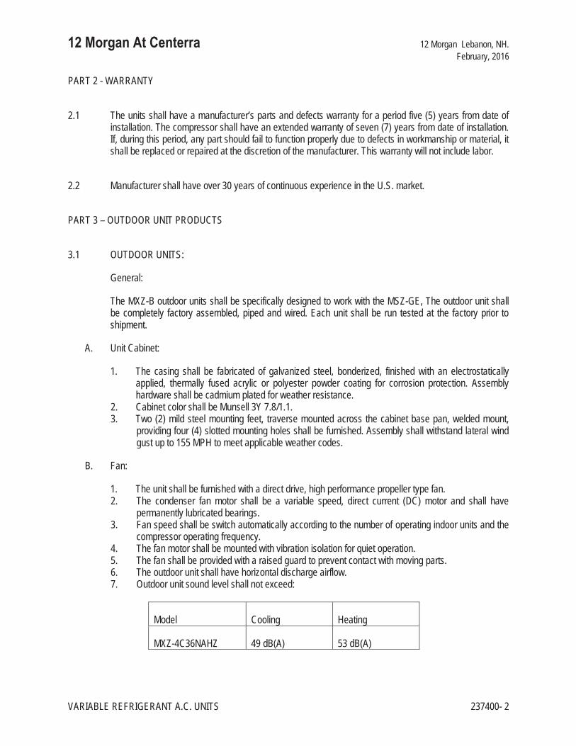
PART 2 - WARRANTY
2.1 The units shall have a manufacturer’s parts and defects warranty for a period five (5) years from date of installation. The compressor shall have an extended warranty of seven (7) years from date of installation. If, during this period, any part should fail to function properly due to defects in workmanship or material, it shall be replaced or repaired at the discretion of the manufacturer. This warranty will not include labor.
2.2 Manufacturer shall have over 30 years of continuous experience in the U.S. market.
PART 3 – OUTDOOR UNIT PRODUCTS
3.1 OUTDOOR UNITS:
General:
The MXZ-B outdoor units shall be specifically designed to work with the MSZ-GE, The outdoor unit shall be completely factory assembled, piped and wired. Each unit shall be run tested at the factory prior to shipment.
A. Unit Cabinet:
1. The casing shall be fabricated of galvanized steel, bonderized, finished with an electrostatically applied, thermally fused acrylic or polyester powder coating for corrosion protection. Assembly hardware shall be cadmium plated for weather resistance.
2. Cabinet color shall be Munsell 3Y 7.8/1.1. 3. Two (2) mild steel mounting feet, traverse mounted across the cabinet base pan, welded mount,
providing four (4) slotted mounting holes shall be furnished. Assembly shall withstand lateral wind gust up to 155 MPH to meet applicable weather codes.
B. Fan:
1. The unit shall be furnished with a direct drive, high performance propeller type fan. 2. The condenser fan motor shall be a variable speed, direct current (DC) motor and shall have
permanently lubricated bearings. 3. Fan speed shall be switch automatically according to the number of operating indoor units and the
compressor operating frequency. 4. The fan motor shall be mounted with vibration isolation for quiet operation. 5. The fan shall be provided with a raised guard to prevent contact with moving parts. 6. The outdoor unit shall have horizontal discharge airflow. 7. Outdoor unit sound level shall not exceed:
Model Cooling Heating
MXZ-4C36NAHZ 49 dB(A) 53 dB(A)

12 Morgan At Centerra 12 Morgan Lebanon, NH. February, 2016
VARIABLE REFRIGERANT A.C. UNITS 237400- 3
C. Coil:
1. The outdoor unit coil shall be of nonferrous construction with lanced or corrugated plate fins on copper tubing.
2. The coil shall be protected with an integral guard. 3. Refrigerant flow from the outdoor unit to the indoor units shall be independently controlled by
means of individual electronic linear expansion valves for each indoor unit. 4. Outdoor unit shall be pre-charged with sufficient R-410a refrigerant to satisfy the outdoor unit coil
and compressor. 5. All refrigerant lines between outdoor and indoor units shall be of annealed, refrigeration grade
copper tubing, ARC Type, meeting ASTM B280 requirements, individually insulated in twin-tube, flexible, closed-cell, CFC-free (ozone depletion potential of zero), elastomeric material for the insulation of refrigerant pipes and tubes with thermal conductivity equal to or better than 0.27 BTU-inch/hour per Sq Ft / °F, a water vapor transmission equal to or better than 0.08 Perm-inch and superior fire ratings such that insulation will not contribute significantly to fire and up to 1” thick insulation shall have a Flame-Spread Index of less than 25 and a Smoke-development Index of less than 50 as tested by ASTM E 84 and CAN / ULC S-102.
6. All refrigerant connections between outdoor and indoor units shall be flare type.
D. Compressor:
1. The compressor shall be a high performance, hermetic, inverter driven, variable speed, scroll type manufactured by Mitsubishi Electric Corporation.
2. The compressor motor shall be direct current (DC) type equipped with a factory supplied and installed inverter drive package.
3. The outdoor unit shall be equipped with a suction side refrigerant accumulator. 4. The compressor will be equipped with an internal thermal overload. 5. The compressor shall be mounted to avoid the transmission of vibration.
E. Branch Boxes:
1. The outdoor unit shall have a 3/8” liquid line connection and a 5/8” gas line connection. Pipe lines running from the outdoor unit shall connect to a 3-port, a 5-port branch box, or a combination of both. The port connections on the branch boxes are as described in the table below:
Branch Box Model Number PAC-MKA30BC
Outdoor Unit to Branch Box
Liquid line 3/8”
Gas line 5/8”
Branch Box to Indoor Unit
Port A B C
Liquid line 1/4” 1/4” 1/4”
Gas line 3/8” 3/8” 3/8”
2. The outdoor unit must be connected to at least one branch box. 3. The branch boxes shall be installed indoors in an area with a temperature between -13ºF and
115ºF and a relative humidity of 80% or lower.

12 Morgan At Centerra 12 Morgan Lebanon, NH. February, 2016
VARIABLE REFRIGERANT A.C. UNITS 237400- 4
F. Piping Requirements:
1. The outdoor unit must have the ability to operate within the following refrigerant piping and height limitations without the need for line size changes, traps or additional oil.
2. Piping Lengths:
Model MXZ-4C36NAHZ
Height Differential – Indoor unit above outdoor unit 131 feet (Max)
Height Differential – Indoor unit below outdoor unit 164 feet (Max)
Distance between outdoor unit and farthest indoor unit 262 feet (Max)
Distance between outdoor unit and branch box 180 feet (Max)
Length from branch box to farthest indoor unit 82 feet (Max)
Total length between branch box and all connected indoor units 311 feet (Max)
Total Length 492 feet (Max)
3. Line sets shall be sized in accordance to equipment manufacture specifications. 4. Copper shall be dehydrated, nitrogen purged, sealed and of a consistent annealed temper, bright
and thoroughly dried 5. Tube shall be manufactured in accordance with ASTM B280 and ANSI B9.1, refrigeration industry
standards. 6. Line sets shall be individually insulated with 1/2” wall thickness consistent with low-density
polyethylene closed cell foam in accordance to ASTM C 1427-07, type I (tubular), grade I (insulation material for use on typical commercial system non-crosslinked).
7. Insulation shall have an outer surface covered by additional polyethylene jacket, white color, to protect foam insulation from tearing during installation process, UV Resistant and paintable.
G. Electrical:
1. The unit electrical power shall be 208/230 volts, 1-phase, 60 hertz. 2. The unit shall be capable of satisfactory operation within voltage limits of 187 volts to 253 volts. 3. The outdoor unit shall be controlled by the microprocessors located in the indoor unit and in the
outdoor unit communicating system status, operation, and instructions digitally over A-Control – a system directing that the indoor unit be powered directly from the outdoor unit using a 3-wire, 14 gauge AWG connection plus ground.
4. The outdoor unit shall be equipped with Pulse Amplitude Modulation (PAM) compressor inverter drive control for maximum efficiency with minimum power consumption.
END OF SECTION 237400

12 Morgan At Centerra 12 Morgan Lebanon, NH. February, 2016
DUCTLESS SPLIT AIR CONDITIONING SYSTEM 237410 - 1
SECTION 237410 - DUCTLESS SPLIT AIR CONDITIONING SYSTEM
PART 1 - GENERAL
1.1 SYSTEM DESCRIPTION
A. The Hyper Heat Inverter Heat Pump system shall be a Mitsubishi Electric split system with Variable Speed Inverter Compressor technology. The system shall consist of a Hyper Heat Inverter horizontal discharge, single phase outdoor unit, a matched capacity indoor section that shall be equipped with a wired wall mounted and/or wireless handheld remote controller. All systems shall be Energy Star Qualified and listed.
1.2 OUTDOOR UNIT RATED CAPACITY
A. The units shall be tested by a Nationally Recognized Testing Laboratory (NRTL) and shall bear the ETL label.
B. All wiring shall be in accordance with the National Electrical Code (N.E.C.) and local codes as required.
C. The units shall be rated in accordance with Air-conditioning, Heating, and Refrigeration Institute’s (AHRI) Standard 240 and bear the AHRI Certification label.
D. The units shall be manufactured in a facility registered to ISO 9001 and ISO 14001, which is a set of standards applying to environmental protection set by the International Standard Organization (ISO).
E. A dry air holding charge shall be provided in the indoor section.
F. The outdoor unit shall be pre-charged with R-410a refrigerant for 100 feet (30 meters) of refrigerant tubing.
G. System efficiency shall meet or exceed SEER / HSPF values below:
When used with Indoor Unit SEER 36,000 BTU HSPF 36,000 BTU
PCA Ceiling Suspended Type 16.6 10.3
PEA / PEAD Ducted Type 16.8 10.4
Outdoor Units
Model Numbers Cooling Heating
PUZ-HA36NHA4 33,500 38,000

12 Morgan At Centerra 12 Morgan Lebanon, NH. February, 2016
DUCTLESS SPLIT AIR CONDITIONING SYSTEM 237410 - 2
PKA Wall Mounted Type 16.2 10.0
PLA Ceiling Recessed Cassette Type 17.0 10.0
1.3 DELIVERY, STORAGE AND HANDLING
A. Unit shall be stored and handled according to the manufacturer’s recommendations.
B. The controller shall be shipped separately and shall be able to withstand 105°F storage temperatures and 95% relative humidity without adverse effect.
PART 2 - WARRANTY
2.1 The units shall have a manufacturer’s parts and defects warranty for a period five (5) year from date of installation. The compressor shall have a warranty of seven (7) years from date of installation. If, during this period, any part should fail to function properly due to defects in workmanship or material, it shall be replaced or repaired at the discretion of the manufacturer. This warranty does not include labor.
2.2 Manufacturer shall have over thirty (30) years of continuous experience in the U.S. market.
PART 3 - OUTDOOR UNIT DESIGN:
3.1 The outdoor unit shall be compatible with the PKA – (wall mounted). The connected indoor unit shall be of the same capacity as the outdoor unit. Option: Indoor unit Twinning is allowed as described in 3.02 below.
3.2 Model PUZ-HA36NHA4 shall have the option to connect to two, one-half capacity (18,000 BTU/h), indoor units (PEA, PKA and/or PLA type), within the same confined space, to improve air distribution (total combined indoor unit capacity shall be equal to that of the outdoor unit).
3.3 The outdoor unit shall be equipped with an electronic control board that interfaces with the indoor unit to perform all necessary operation functions.
3.4 The outdoor unit shall be capable of Hyper Heating performance delivering 100% rated heating capacity down to +5° F and 75% rated heating capacity at -13° F outdoor ambient temperature. Further, the outdoor unit shall be capable of cooling operating at 0°F (-18°C) ambient temperature without additional low ambient controls (optional wind baffle shall be required).

12 Morgan At Centerra 12 Morgan Lebanon, NH. February, 2016
DUCTLESS SPLIT AIR CONDITIONING SYSTEM 237410 - 3
3.5 The outdoor unit shall be able to operate with a maximum height difference of 100 feet (30 meters) between indoor and outdoor units.
3.6 System shall operate at up to a maximum refrigerant tubing length of 245 feet (75 meters) between indoor and outdoor units without the need for line size changes, traps or additional oil. Outdoor units shall be factory pre-charged for a maximum of 100 feet (30 meters) of refrigerant tubing.
3.7 The outdoor unit shall be completely factory assembled, piped, and wired. Each unit must be test run at the factory.
3.8 OUTDOOR UNIT SOUND LEVEL SHALL NOT EXCEED:
3.9 CABINET
A. The casing shall be constructed from galvanized steel plate, finished with an electrostatically applied, thermally fused acrylic or polyester powder coating for corrosion protection and have a Munsell 3Y 7.8/1.1 finish.
B. Mounting feet shall be provided and shall be welded to the base of the cabinet and be of sufficient size to afford reliable equipment mount and stability.
C. Easy access shall be afforded to all serviceable parts by means of removable panel sections.
D. The fan grill shall be of ABS plastic.
E. Cabinet mounting and construction shall be sufficient to withstand 155 MPH wind speed conditions for use in Hurricane condition areas. Mounting, base support, and other installation to meet Hurricane Code Conditions shall be by others.
3.10 FAN
A. Models PUZ- 36NHA4 shall be furnished with two (2) DC fan motors.
B. The fan blades shall be of high performance, aerodynamic design for quiet operation, and the fan motor bearings shall be permanently lubricated.
Outdoor Unit Sound Level
Model Numbers Cooling Heating
PUZ-A36NHA4 52 dB(A) 53 dB(A)

12 Morgan At Centerra 12 Morgan Lebanon, NH. February, 2016
DUCTLESS SPLIT AIR CONDITIONING SYSTEM 237410 - 4
C. The outdoor unit shall have horizontal discharge airflow. The fan shall be mounted in front of the coil, pulling air across it from the rear and dispelling it through the front. The fans shall be provided with a raised guard to prevent external contact with moving parts.
3.11 COIL
A. The L shaped condenser coil shall be of copper tubing with flat aluminum fins to reduce debris build up and allow maximum airflow. The coil shall be protected with an integral metal guard.
B. Refrigerant flow from the condenser shall be controlled by means of an electronic linear expansion valve (LEV) metering device. The LEV shall be controlled by a microprocessor controlled step motor.
C. All refrigerant lines between outdoor and indoor units shall be of annealed, refrigeration grade copper tubing, ARC Type, meeting ASTM B280 requirements, individually insulated in twin-tube, flexible, closed-cell, CFC-free (ozone depletion potential of zero), elastomeric material for the insulation of refrigerant pipes and tubes with thermal conductivity equal to or better than 0.27 BTU-inch/hour per Sq Ft / °F, a water vapor transmission equal to or better than 0.08 Perm-inch and superior fire ratings such that insulation will not contribute significantly to fire and up to 1” thick insulation shall have a - Flame-Spread Index of less than 25 and a Smoke-development Index of less than 50 as tested by ASTM E 84 and CAN / ULC S-102. All refrigerant line connections shall be flare type sized as required and tightened to manufacturers specified torque value.
3.12 COMPRESSOR
A. The compressor for models PUZ-HA36NHA4 shall be a Mitsubishi Electric, injection port equipped, Frame Compliant Scroll compressor with Variable Speed Inverter Drive Technology.
B. The compressor shall be driven by inverter circuit to control compressor speed. The compressor speed shall dynamically vary to match the room loads, increasing the efficiency of the system which shall result in significant energy savings.
C. To prevent liquid from accumulating in the compressor during the off cycle, a minimal amount of current shall be automatically, intermittently applied to the compressor motor windings to maintain sufficient heat to vaporize any refrigerant. No crankcase heater is to be used.
D. The outdoor unit shall have an accumulator and high pressure safety switch. The compressor shall be mounted to avoid the transmission of vibration.
3.13 ELECTRICAL
A. The electrical power of the unit shall be 208volts or 230 volts, single phase, 60 hertz. The unit shall be capable of satisfactory operation within voltage limits of 187 volts to 253 volts.
B. Power for the indoor unit shall be supplied from the outdoor unit via Mitsubishi Electric A-Control using three (3) fourteen (14) gauge AWG conductors plus ground wire connecting the units.
C. The outdoor unit shall be controlled by the microprocessor located in the indoor unit.

12 Morgan At Centerra 12 Morgan Lebanon, NH. February, 2016
DUCTLESS SPLIT AIR CONDITIONING SYSTEM 237410 - 5
D. The control signal between the indoor unit and the outdoor unit shall be pulse signal 24 volts DC.
E. The unit shall have Pulse Amplitude Modulation circuit to utilize 98% of input power supply.
3.14 OPERATING RANGE:
Operating Range Indoor Air Intake Temperature Outdoor Air Intake Temperature
Cooling
Maximum D.B. 90°F (32°C) W.B. 73°F (23°C) D.B. 115°F (46°C)
Minimum D.B. 66°F (19°C) W.B. 59°F (15°C) D.B. 0°F (-18°C)*
Heating
Maximum D.B. 83°F (28°C) D.B. 70°F (21.1°C) W.B. 59°F (15°C)
Minimum D.B. 63°F (17°C) D.B. -13°F (-25°C) W.B. -13°F (-25°C)
A. Unit shall be able to provide 100% capacity when operating at 0ºF outdoor air temperature and a wind baffle is used.
3.15 PIPING REQUIREMENTS
A. The outdoor unit must have the ability to operate within the following refrigerant piping and height limitations without the need for line size, traps or additional oil.
B. Maximum pipe lengths and height difference 245’ max length with 100’ max height difference
C. Line sets shall be sized in accordance to the equipment manufacture specifications.
D. Copper shall be dehydrated, nitrogen purged, sealed and of a consistent annealed temper, bright and thoroughly dried.
E. Tube shall be manufactured in accordance with ASTM B280 and ANSI B9.1, refrigeration industry standards.
F. Line sets shall be individually insulated with ½” wall thickness consistent with low-density polyethylene closed cell foam in accordance to ATSM C 1427-07, type I (tubular), grade I (insulation material for use on typical commercial system non-crosslinked).
G. Insulation shall have an outer surface covered by additional polyethylene jacket, whit colot, to protect foam insulation from tearing during the installation process, UV resistant and paitable.

12 Morgan At Centerra 12 Morgan Lebanon, NH. February, 2016
DUCTLESS SPLIT AIR CONDITIONING SYSTEM 237410 - 6
PART 4 - INDOOR UNIT SELECTION AND SPECIFICATION
4.1 PKA WALL MOUNTED TYPE
The indoor unit shall be factory assembled, wired and tested. Contained within the unit shall be all factory wiring and internal piping, control circuit board and fan motor. The unit, in conjunction with the wired, wall mounted controller or wireless handheld controller, shall have a self-diagnostic function, 3-minute time delay mechanism, an auto restart function, and a test run switch. Indoor unit and refrigerant pipes shall be purged with dry nitrogen before shipment from the factory.
Wall Mounted Type Indoor Units
Model Number Rated Cooling Capacity
Rated Heating Capacity @ 47ºF*
Maximum Heating Capacity @ 5ºF*
PKA-A36KA4 33,500 38,000 38,000
A. Unit Cabinet: The cabinet shall be formed from high strength molded plastic with smooth finish, flat front panel design with access for filter. Cabinet color shall be white – Munsell 1.0Y 9.2/0.2. The unit shall be wall mounted by means of a factory supplied, pre-drilled, mounting plate.
B. Fan: The indoor unit fan shall be high performance, double inlet, forward curve, direct drive sirocco fan with a single motor. The fans shall be statically and dynamically balanced and run on a motor with permanently lubricated bearings. The indoor fan shall consist of three (3) speeds: Low, Mid, and Hi and Auto. The fan shall have a selectable Auto fan setting that will adjust the fan speed based on the difference between controller set-point and space temperature.
C. Indoor unit sound level shall not exceed the levels below:
Model Number Low Speed Mid Speed High Speed PKA-A36KA4 43 dB(A) 46 dB(A) 49 dB(A)
D. Vane: There shall be a motorized horizontal vane to automatically direct air flow in a horizontal and downward direction for uniform air distribution. The horizontal vane shall significantly decrease downward air resistance for lower sound levels, and shall close the outlet port when operation is stopped. There shall also be a set of vertical vanes to provide horizontal swing airflow movement.
E. Filter: Return air shall be filtered by means of an easily removable washable filter.
F. Coil: The evaporator coil shall be of nonferrous construction with pre-coated aluminum strake fins on copper tubing. The multi-angled heat exchanger shall have a modified fin shape that reduces air resistance for a smoother, quieter airflow. All tube joints shall be brazed with PhosCopper or silver alloy. The coils shall be pressure tested at the factory. A condensate pan and drain shall be provided under the coil. [Option: A condensate mini-pump shall be provided to provide a method of condensate disposal when a gravity drain is not available.]
G. Electrical: The electrical power of the unit shall be 208 volts or 230 volts, 1 phase, 60 hertz. The system shall be capable of satisfactory operation within voltage limits of 198 volts to 253 volts. The power to the indoor unit shall be supplied from the outdoor unit, using the Mitsubishi Electric A-Control system. For A-

12 Morgan At Centerra 12 Morgan Lebanon, NH. February, 2016
DUCTLESS SPLIT AIR CONDITIONING SYSTEM 237410 - 7
Control, a three (3) conductor AWG-14 wire with ground shall provide power feed and bi-directional control transmission between the outdoor and indoor units.
H. Performance: Each system shall perform in accordance to the ratings shown in the table below. Cooling performance shall be based on 80°F DB, 67°F WB (26.7°C DB, 19.4°C WB) for the indoor unit and 95°F DB, 75°F WB (35°C DB, 29.3°C WB) for the outdoor unit. Heating performance shall be based on 70°F DB, 60°F WB (21.1°C DB, 15.6°C WB) for the indoor unit and 47°F DB, 15°F WB (8.3°C DB, 6.1°C WB) for the outdoor unit.
System Model
Number
Cooling Capacity
Btu/h
Heating Capacity
Btu/h TPW
Cooling TPW
Heating SEER HSPF IV (V)
CFM (Hi/Dry)
PKA-A36KA4
18,000 – 34,200
18,000 – 40,000 2,790 3,410 16.2 10.0 (7.8) 920
*TPW = Total Power Watts
I. System Control: The control system shall consist of a minimum of two (2) microprocessors, one on each indoor and outdoor unit, interconnected by a single non-polar two-wire cable. The microprocessor located in the indoor unit shall have the capability of monitoring return air temperature and indoor coil temperature, receiving and processing commands from a wireless or wired controller, providing emergency operation and controlling the outdoor unit. The control signal between the indoor and outdoor unit shall be pulse signal 24 volts DC. Indoor units shall have the ability to control supplemental heat via connector CN152 and a 12 VDC output.
J. The indoor unit control board shall have auxiliary control contact connectors to provide:
Function / Model PKA
CN-2L – Lossnay Control X
CN-24(152) Back-up Heat X
CN-32 – Remote Switch X
CN-51 – Central Control X
CN-105 – IT Terminal X *X = Included
4.2 REMOTE CONTROLLERS Remote controllers need to be ordered separately from the unit.
A. Wired Remote Controller (PAR-31MAA)
1. The Wired Remote Controller (PAR-31MAA) shall be approximately 5” x 5” in size and white in color with a light-green LCD display. The PAR-31MAA shall support a selection from multiple

12 Morgan At Centerra 12 Morgan Lebanon, NH. February, 2016
DUCTLESS SPLIT AIR CONDITIONING SYSTEM 237410 - 8
languages (Spanish, German, Japanese, Chinese, English, Russian, Italian, or French) for display information. There shall be a built-in weekly timer with up to 8 pattern settings per day. The controller shall consist of an On/Off button, Increase/Decrease Set Temperature buttons, a Cool/Auto/Fan/Dry mode selector, a Timer Menu button, a Timer On/Off button, Set Time buttons, a Fan Speed selector, a Ventilation button, a Test Run button, and a Check Mode button. The controller shall have a built-in temperature sensor. Temperature shall be displayed in either Fahrenheit (°F) or Celsius (°C), and Temperature changes shall be by increments of 1°F (0.5°C). The PAR-31MAA shall have the capability of controlling up to a maximum of 16 systems, as a group with the same mode and set-point for all, at a maximum developed control cable distance of 1,500 feet (500 meters).
2. The control voltage from the wired controller to the indoor unit shall be 12/24 volts, DC. Field wiring shall run directly from the indoor unit to the wall mounted controller with no splices. Up to two wired controllers shall be able to be used to control one unit.
3. The basic functions are:
Wired Remote Controller (PAR-31MAA) Item Description
Number of Units Controllable 16 units as 1 group ON/OFF Run and stop operation Operation Mode Switches between Cool/Dry/Auto/Fan/Heat. Temperature Setting (Range and modes depend on connected unit model)
Sets the setpoint temperature in the following range Cool/Dry: 67°F-87°F Heat: 63°F-83°F Auto: 67°F-83°F
Fan Speed Setting (Range and modes depend on connected unit model)
Hi/Mid-2/Mid-1/Low/Auto
Air Flow Direction Setting (Air flow direction settings depend on the unit model)
Air flow direction angles 100%-80%-60%-40%, Swing.
Weekly Scheduler ON/OFF/Temperature setting can be done up to 8 times one day in the week. The time can be set by the 1-minute interval.
Operating Conditions Display Setpoint and room temperature. Sensing can be done at the remote controller or the indoor unit depending on the indoor unit dipswitch setting Liquid, discharge, indoor and outdoor pipe temperatures LEV opening pulses, sub cooling and discharge super heat Compressor Operating Conditions: Running current, frequency, input voltage, On/Off status and operating time
Error When an error is currently occurring on an air conditioner unit, the afflicted unit and the error code are displayed

12 Morgan At Centerra 12 Morgan Lebanon, NH. February, 2016
DUCTLESS SPLIT AIR CONDITIONING SYSTEM 237410 - 9
Wired Remote Controller (PAR-31MAA) Item Description
Ventilation Equipment Up to 16 indoor units can be connected to an interlocked system that has one LOSSNAY unit. LOSSNAY items that can be set are “Hi”, “Low”, and “Stop”. Ventilation mode switching is not available.
Auto Lock Out Function Setting/releasing of simplified locking for remote control buttons can be performed.
Locking of all buttons
Locking of all buttons except ON/OFF button
END OF SECTION 237410


12 Morgan At Centerra 12 Morgan Lebanon, NH. February, 2016
CONVECTION HEATING UNITS 238200- 1
SECTION 238200 - CONVECTION HEATING UNITS
PART 1 - GENERAL
1.1 SCOPE
A. Cabinet Heaters: Trane "Force-flo", Sterling or Vulcan product. Coordinate location with G.C. Units shall be multi-speed with internal thermal overload protection and service disconnect switch. Furnish with T.A. filters and factory applied baked-on enamel finish. Color selection by Architect.
B. Unit Heaters: Trane, Sterling, Vulcan or equal product of capacity indicated, hot water type, with fan inlet screen, and adjustable discharge louver.
END OF SECTION 238200


12 Morgan At Centerra 12 Morgan Lebanon, NH. February, 2016
ELECTRIC BASEBOARD 238300- 1
SECTION 238300 - ELECTRIC BASEBOARD
PART 1 - GENERAL
1.1 SCOPE
A. Electric Baseboard: QMARK, Cadet or Runtal product. Furnish with enclosure, access doors, and all trim required for complete installation. Furnish enclosure panels and trim with prime coat finish for final painting in the field.
END OF SECTION 238300