1.2 physical contraints - lbhf · 1.2 physical contraints west brompton station is a grade ii...
TRANSCRIPT

1.2 Physical Contraints
West Brompton Station is a Grade II Listed building on the English
Heritage register. The architectural features that are covered by
the Listed Building protection include the perimeter walls and
roof structure of the station building as well as the decorative cast
iron and timber footbridges and stairs in the train shed. Any
enhancement proposals will need to have regard of these
heritage assets.
It is not considered that the internal partitions that comprise the
ticketing suite in the main station building are protected by the
Listed Building status, as they are a product of many alterations
that have been carried out over the station's life.
The station is located on Old Brompton Road to the north, with
the neighbouring site to the east owned by EDF Energy and a
small nature reserve to the west of the West London Line
platforms. Each of these constitutes property boundaries that
limit potential expansion of the station’s facilities.
The eastbound District line platform has a 7m high back wall at
the boundary with the EDF Energy site. Attached to the wall are a
number of low voltage power cables supplying lights. It is not
believed that there are any signi#cant communications services
attached to the wall, or buried in the platform construction.
The westbound District Line platform is e$ectively an island
platform, linked with the eastbound WLL platform. The galva-
nised steel palisade fence that separates the two platforms is
considered a ‘soft boundary’, as the fence currently allows the
WLL line to remain open after the London Underground network
has closed at the end of each day.
The position of this boundary may be &exible providing su%cient
space is retained for safe passenger circulation on each platform.
8 WEST BROMPTON STATION ENHANCEMENTS STAGE C REPORT
EDF Energy Site
Dot Matrix
Service Update
Banner
Grade II Listed
Structure
Grade II Listed
Station Building
Passenger
Lift
Passenger
Lift
Equipment on Platform 2 Property boundary with EDF Energy
PLATFORM 1
PLATFORM
2PLATFO
RM 3
PLATFORM
4
Physical Constraints Model
WEST BROMPTON STATION ENHANCEMENTS STAGE C REPORT 9
EDF Energy Site
Dot Matrix
Service Update
Banner
Grade II Listed
Structure
Grade II Listed
Station Building
Passenger
Lift Passenger
Lift
Grade II Listed
Decorated Overbridges
A number of services are located on the westbound platform
near to the train shed, including lamp-posts and a dot-matrix
service update banner.
For the provision of step-free access to platform 1, this study
reviews potential locations for a passenger lift on the platform.
The current width of platform 1 varies between 4m and 5m, with
the narrowest section at the station end.
The platform width is considered an important constraint as the
provision of a passenger lift will create a narrowing of the
platform in a localised area. The minimum width of platform
permissible by London Underground Station Planning Standards
and Guidelines is 2.5m
PLATFORM 4
PLATFORM 3
PLATFORM 2
PLATFORM 1
Decorative Iron Footbridges Grade II Listed Facade
Physical Constraints Model
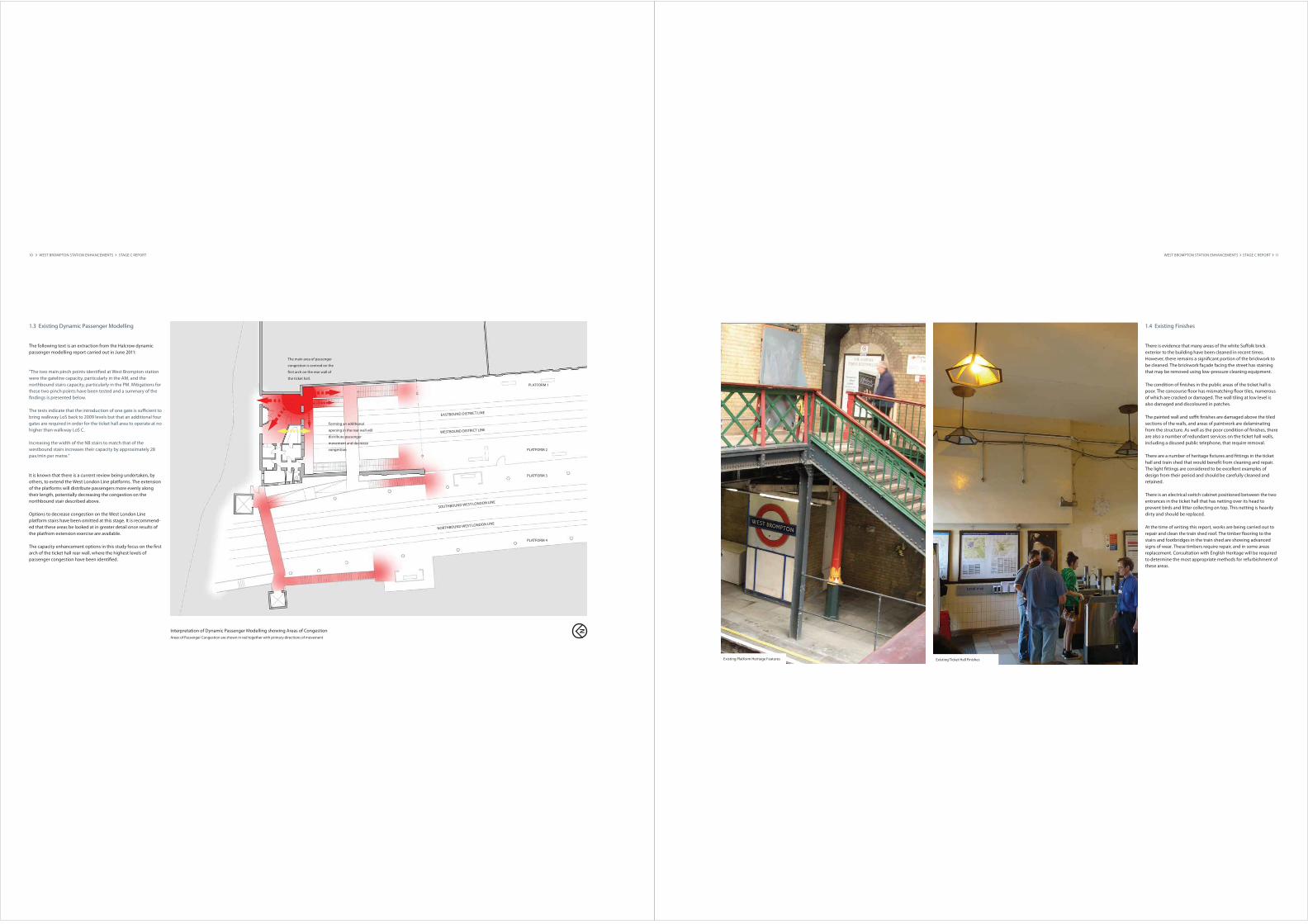
1.3 Existing Dynamic Passenger Modelling
The following text is an extraction from the Halcrow dynamic
passenger modelling report carried out in June 2011:
"The two main pinch points identi#ed at West Brompton station
were the gateline capacity, particularly in the AM, and the
northbound stairs capacity, particularly in the PM. Mitigations for
these two pinch points have been tested and a summary of the
#ndings is presented below.
The tests indicate that the introduction of one gate is su%cient to
bring walkway LoS back to 2009 levels but that an additional four
gates are required in order for the ticket hall area to operate at no
higher than walkway LoS C.
Increasing the width of the NB stairs to match that of the
westbound stairs increases their capacity by approximately 28
pax/min per metre."
It is known that there is a current review being undertaken, by
others, to extend the West London Line platforms. The extension
of the platforms will distribute passengers more evenly along
their length, potentially decreasing the congestion on the
northbound stair described above.
Options to decrease congestion on the West London Line
platform stairs have been omitted at this stage. It is recommend-
ed that these areas be looked at in greater detail once results of
the platfrom extension exercise are available.
The capacity enhancement options in this study focus on the #rst
arch of the ticket hall rear wall, where the highest levels of
passenger congestion have been identi#ed.
10 WEST BROMPTON STATION ENHANCEMENTS STAGE C REPORT
Interpretation of Dynamic Passenger Modelling showing Areas of Congestion
Areas of Passenger Congestion are shown in red together with primary directions of movement
The main area of passenger
congestion is centred on the
#rst arch on the rear wall of
the ticket hall.
Forming an additional
opening in the rear wall will
distribute passenger
movement and decrease
congestion
PLATFORM 1
PLATFORM 2
PLATFORM 3
PLATFORM 4
EASTBOUND DISTRICT LINE
WESTBOUND DISTRICT LINE
SOUTHBOUND WEST LONDON LINE
NORTHBOUND WEST LONDON LINE
WEST BROMPTON STATION ENHANCEMENTS STAGE C REPORT 11
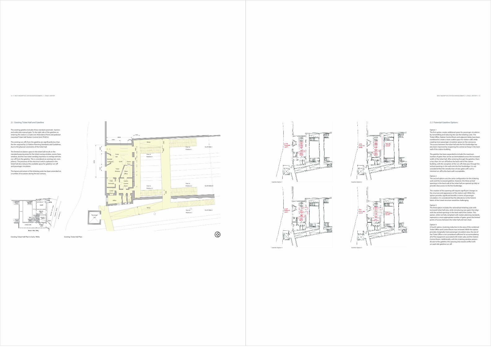
Existing Platform Heritage Features Existing Ticket Hall Finishes
1.4 Existing Finishes
There is evidence that many areas of the white Su$olk brick
exterior to the building have been cleaned in recent times.
However, there remains a signi#cant portion of the brickwork to
be cleaned. The brickwork façade facing the street has staining
that may be removed using low-pressure cleaning equipment.
The condition of #nishes in the public areas of the ticket hall is
poor. The concourse &oor has mismatching &oor tiles, numerous
of which are cracked or damaged. The wall tiling at low level is
also damaged and discoloured in patches.
The painted wall and so%t #nishes are damaged above the tiled
sections of the walls, and areas of paintwork are delaminating
from the structure. As well as the poor condition of #nishes, there
are also a number of redundant services on the ticket hall walls,
including a disused public telephone, that require removal.
There are a number of heritage #xtures and #ttings in the ticket
hall and train shed that would bene#t from cleaning and repair.
The light #ttings are considered to be excellent examples of
design from their period and should be carefully cleaned and
retained.
There is an electrical switch cabinet positioned between the two
entrances in the ticket hall that has netting over its head to
prevent birds and litter collecting on top. This netting is heavily
dirty and should be replaced.
At the time of writing this report, works are being carried out to
repair and clean the train shed roof. The timber &ooring to the
stairs and footbridges in the train shed are showing advanced
signs of wear. These timbers require repair, and in some areas
replacement. Consultation with English Heritage will be required
to determine the most appropriate methods for refurbishment of
these areas.

12 WEST BROMPTON STATION ENHANCEMENTS STAGE C REPORT
2 CAPACITY ENHANCEMENT
WEST BROMPTON STATION ENHANCEMENTS STAGE C REPORT 13
2.1 Existing Ticket Hall and Gateline
The existing gateline includes three standard automatic barriers
and wide aisle manual gate. To the right side of the gateline on
entering the station is a Gate Line Attendance Point and pedestal
mounted Ticket Hall Station Control Unit (THSCU).
The existing run-o$s from the gateline are signi#cantly less than
the 6m required by LU Station Planning Standards and Guidelines
due to the physical constraints of the ticket hall.
The limited circulation space in the ticket hall results in the
standard queuing areas for the ticket issuing window, excess fares
window, and the two ticket vending machines to overlap with the
run-o$ from the gateline. This is considered an existing non-com-
pliance. The presence of the electrical switch cupboard in the
ticket hall also reduces the available space for gateline run-o$
and passenger circulation.
The layout and extent of the ticketing suite has been amended on
a number of occasions during the last century.
14 WEST BROMPTON STATION ENHANCEMENTS STAGE C REPORT
POM
Enclosure
Ticket
O%ce
Station
Control
Room
Ticket
Hall
Eletrical
Cupboard
Stair to
Platform 1
Stair to
Platform 1
Stair to
Platform 2
Stair to
Platform 2
Ramp
GLAP
O%ce
Locker
Room
Passenger
Lift
Ramp
Stair to
Platform 3
Existing Ticket Hall Plan
16
30
115
0
14
80
122
0
87
00
6840
3750 1190
1700
21
00
14
00
14
00
PLATFORM 3
PLATFORM 2
PLATFORM 1
Ticket
Window
Excess
Fares
Existing Ticket Hall Plan in Early 1900s
2.2 Potential Gateline Options
Option 1
The #rst option creates additional space for passenger circulation
by remodelling and reducing the size the ticketing suite. The
Ticket O%ce, Station Control Room and adjacent lobby have been
combined to create a more usable space for station sta$, while
creating more passenger circulation space on the concourse.
The access between the ticket hall and the #rst footbridge has
also been improved by reopening the central archway in the back
wall of the station building.
The gateline has been expanded to include the maximum
number of gates that can be accommodated across the increased
width of the ticket hall. After entering through the gateline, there
is less than 2m run-o$ before the back wall of the station
building, with the exception of the run-o$s that pass through the
arched openings in the wall onto the #rst footbridge. It is not
considered that the introduction of new gates with such a
minimal run-o$ to the back wall is acceptable.
Option 2
The second option uses the same con#guration for the ticketing
suite and the increased gateline, however, the three arched
openings in the back wall of the ticket hall are opened up fully to
provide clear access to the #rst footbridge .
The creation of this opening will require signi#cant changes to
the structure and appearance of the station wall. While this
option provides signi#cant bene#ts in terms of passenger
circulation, it is considered that the alterations to the historic
fabric of the Listed structure would be challenging.
Option 3
The third option includes the rationalised ticketing suite with
increased ticket hall area, while introducing new gates that align
with the arched openings in the back wall of the station. This
option, while not fully compliant with station planning standards,
represents a more appropriate number of gates, given the limited
points of access between the ticket hall and train shed.
Option 4
A fourth option, involving reduction in the area of the combined
Ticket O%ce and Control Room was reviewed. While the option
provides marginally more passenger circulation area, the size of
the Ticket O%ce is not considered su%cient for accommodating
all of the equipment associated with ticket sales and the Station
Control Room. Additionally, with the ticketing window perpen-
dicular to the gateline, the queuing area would con&ict with
un-paid side gateline run-o$.
WEST BROMPTON STATION ENHANCEMENTS STAGE C REPORT 15
Gateline Option 1
Gateline Option 4
Gateline Option 2
Gateline Option 3
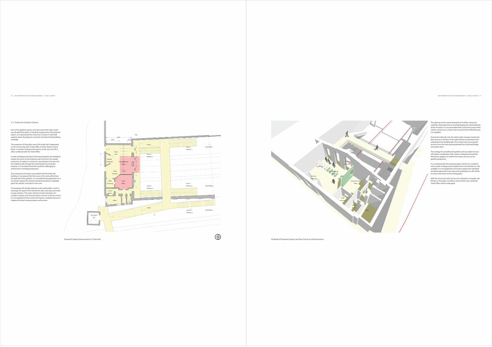
2.3 Preferred Gateline Option
Each of the gateline options were discussed with CapCo and it
was decided that option 3 should be progressed as the preferred
option, as it represented the maximum increase in ticket hall
capacity, given the physical constraints of Grade II listed building
envelope.
The expansion of the public area of the ticket hall is dependent
on the connecting of the Ticket O%ce and the Station Control
Room. In London Underground stations of this size, the SCR is
often combined with the Ticket O%ce.
London Underground Station Planning Standards and Guidelines
require the access to the ticketing suite to be from the unpaid
concourse. An option to construct a second point of access into
the ticketing suite through the street facade was reviewed
however, it is considered that this would be challenging to
achieve from a heritage perspective.
Due to physical constraints assocaiated with the ticket hall
building, it is proposed that the access to the suite will be from
the paid side of the gateline. It is considered that application for a
concession against the relevant standard should be acceptable
given the speci#c constraints in this case.
The proposal will include relatively small scale builder’s work to
rearrange the layout of the blockwork walls, doorways and ticket
issuing windows. The works will also include relocation of a
number of power and communications services in the two rooms.
It is envisaged that these works will require a weekend closure to
migrate the ticket issuing windows and services.
16 WEST BROMPTON STATION ENHANCEMENTS STAGE C REPORT
POM
Enclosure
Ticket
O%ce
Ticket
Hall
Eletrical
Cupboard
Stair to
Platform 1
Stair to
Platform 1
Stair to
Platform 2
Stair to
Platform 2
Ramp
GLAP
O%ce
Locker
Room
Passenger
Lift
Ramp
Stair to
Platform 3
Proposed Capacity Enhancements to Ticket Hall
16
30
115
0
6840
3750 1190
17001
88
03
40
0
3 No. Additional
Gates
PLATFORM 3
PLATFORM 2
PLATFORM 1
Ticket
Window
WEST BROMPTON STATION ENHANCEMENTS STAGE C REPORT 17
3D Model of Proposed Capacity and Step-Free Access Enhancements
POM
Enclosure
Combined Ticket
O%ce
Ticket Hall
Eletrical
Cupboard
GLAP
O%ce
Locker
Room
3 No. Additional
Gates
The opening of the central brickwork arch will be carried out
carefully using hand tools to avoid damaging the Listed elements
of the structure. It is recommended that a structural survey of the
wall be carried out to con#rm that removal of the in#ll blockwork
is acceptable.
During the initial site visit, the station duty manager mentioned
that services in the &oor of the ticket hall are accessed from the
underside of the building slab. This would mean accessing the
services from the tracks passing beneath the Lillie Road Bridge
and station deck.
The strategy for extending the gateline and associated services
will require coordination with London Underground and their
third party suppliers to con#rm the means of access to the
gateline equipment.
It is considered that the proposed gates will be non-compliant
with London Underground standards due to the limited run-o$s
available. It is envisaged that concessions against the standards
should be approved in this case as the proposed run-o$s will be
no worse than those of the existing gates.
With the structural works and services relocations complete, the
#nishes in the public circulation areas and the new combined
Ticket O%ce will be made good.
Archway
Opened up

18 WEST BROMPTON STATION ENHANCEMENTS STAGE C REPORT
3 STEP FREE ACCESS TO PLATFORM 1
WEST BROMPTON STATION ENHANCEMENTS STAGE C REPORT 19
3.1 Existing Platform Access
All four platforms at the station are accessed through the London
Underground ticket hall.
Each of the District Line platforms are accessed by a 1.4m stair
and a 2.1m stair, totaling 3.5m. The westbound platform 2 is also
accessed from platform 3 using a gate in the palisade fence that
separates the two platforms.
The West London Line platforms are accessed by a 1.5m stair and
a passenger lift to each platform. The level connection of
platform 2 to platform 3 also provides step-free access to the
westbound District Line.
Platform 1 is the only platform in the station that does not have
step-free access. For the station to be classi#ed as a fully acces-
sible interchange, a passenger lift is required between the ticket
hall level and platform 1.
20 WEST BROMPTON STATION ENHANCEMENTS STAGE C REPORT
Existing Platform Access Diagram
1.5m
Stair
1.5m
Stair
2.1m
Stair
2.1m
Stair
1.4m
Stair
1.4m
Stair
Passenger Lift to
Platforms 2 and 3
Passenger Lift to
Platform 4
PLATFORM 3
PLATFORM 2
PLATFORM 1
PLATFORM 4
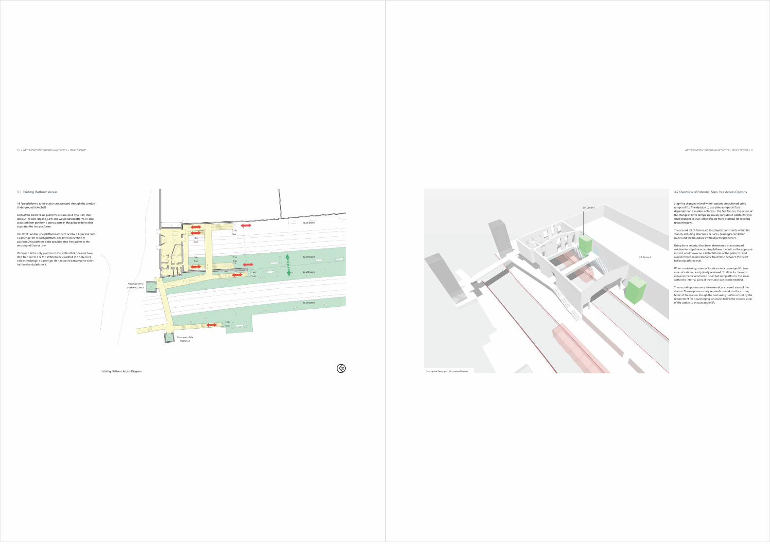
3.2 Overview of Potential Step-free Access Options
Step-free changes in level within stations are achieved using
ramps or lifts. The decision to use either ramps or lifts is
dependent on a number of factors. The #rst factor is the extent of
the change in level. Ramps are usually considered satisfactory for
small changes in level, while lifts are more practical for covering
greater heights.
The second set of factors are the physical constraints within the
station, including structures, services, passenger circulation
routes and the boundaries with adjacent properties.
Using these criteria, it has been determined that a ramped
solution for step-free access to platform 1 would not be appropri-
ate as it would cover an substantial area of the platforms and
would involve an unreasonable travel time between the ticket
hall and platform level.
When considering potential locations for a passenger lift, two
areas of a station are typically reviewed. To allow for the most
convenient access between ticket hall and platforms, the areas
within the internal parts of the station are considered #rst.
The second option covers the external, uncovered areas of the
station. These options usually require less works to the existing
fabric of the station, though the cost saving is often o$-set by the
requirement for new bridging structures to link the covered areas
of the station to the passenger lift.
WEST BROMPTON STATION ENHANCEMENTS STAGE C REPORT 21
Overview of Passenger Lift Location Options
Lift Option 1
Lift Option 2
22 WEST BROMPTON STATION ENHANCEMENTS STAGE C REPORT
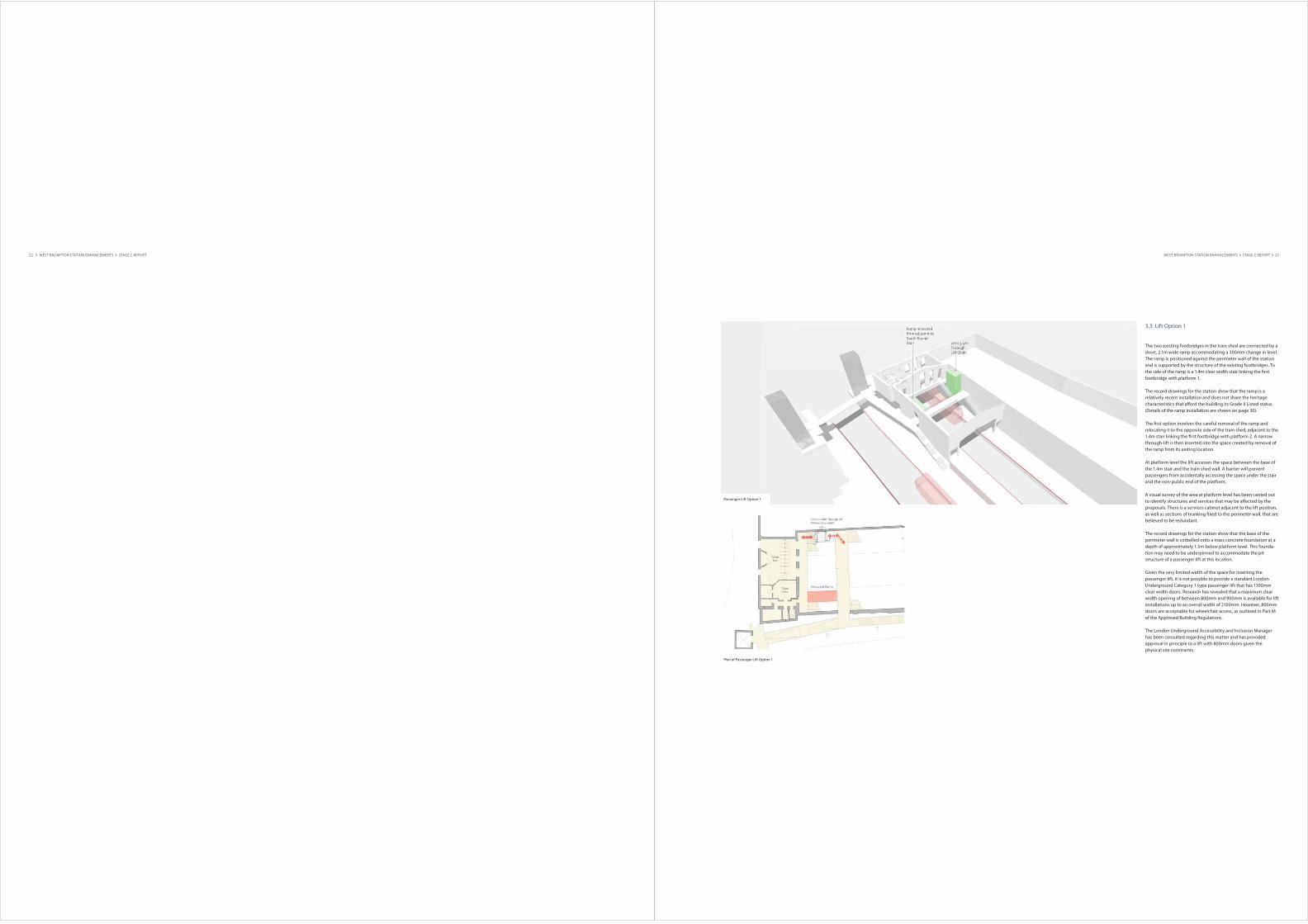
3.3 Lift Option 1
The two existing footbridges in the train shed are connected by a
short, 2.1m wide ramp accommodating a 300mm change in level.
The ramp is positioned against the perimeter wall of the station
and is supported by the structure of the existing footbridges. To
the side of the ramp is a 1.4m clear width stair linking the #rst
footbridge with platform 1.
The record drawings for the station show that the ramp is a
relatively recent installation and does not share the heritage
characteristics that a$ord the building its Grade II Listed status.
(Details of the ramp installation are shown on page 30).
The #rst option involves the careful removal of the ramp and
relocating it to the opposite side of the train shed, adjacent to the
1.4m stair linking the #rst footbridge with platform 2. A narrow
through-lift is then inserted into the space created by removal of
the ramp from its exiting location.
At platform level the lift accesses the space between the base of
the 1.4m stair and the train shed wall. A barrier will prevent
passengers from accidentally accessing the space under the stair
and the non-public end of the platform,
A visual survey of the area at platform level has been carried out
to identify structures and services that may be a$ected by the
proposals. There is a services cabinet adjacent to the lift position,
as well as sections of trunking #xed to the perimeter wall, that are
believed to be redundant.
The record drawings for the station show that the base of the
perimeter wall is corbelled onto a mass concrete foundation at a
depth of approximately 1.5m below platform level. This founda-
tion may need to be underpinned to accommodate the pit
structure of a passenger lift at this location.
Given the very limited width of the space for inserting the
passenger lift, it is not possible to provide a standard London
Underground Category 1 type passenger lift that has 1100mm
clear width doors. Research has revealed that a maximum clear
width opening of between 800mm and 900mm is available for lift
installations up to an overall width of 2100mm. However, 800mm
doors are acceptable for wheelchair access, as outlined in Part M
of the Approved Building Regulations.
The London Underground Accessibility and Inclusion Manager
has been consulted regarding this matter and has provided
approval in principle to a lift with 800mm doors given the
physical site constraints.
WEST BROMPTON STATION ENHANCEMENTS STAGE C REPORT 23
Passenger Lift Option 1
Plan of Passenger Lift Option 1
24 WEST BROMPTON STATION ENHANCEMENTS STAGE C REPORT
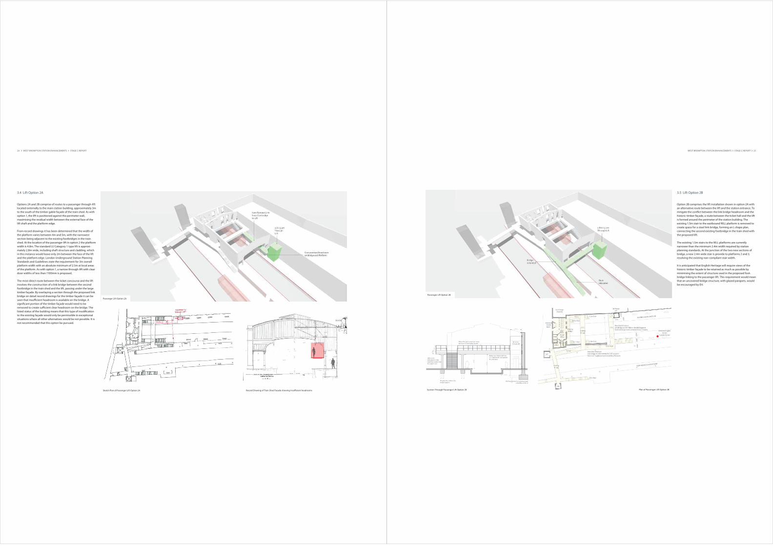
3.4 Lift Option 2A
Options 2A and 2B comprise of routes to a passenger through-lift
located externally to the main station building, approximately 3m
to the south of the timber gable façade of the train shed. As with
option 1, the lift is positioned against the perimeter wall,
maximising the residual width between the external face of the
lift shaft and the platform edge.
From record drawings it has been determined that the width of
the platform varies between 4m and 5m, with the narrowest
section being adjacent to the existing footbridges in the train
shed. At the location of the passenger lift in option 2 the platform
width is 4.8m. The standard LU Category 1 type lift is approxi-
mately 2.8m wide, including shaft structure and cladding, which
in this instance would leave only 2m between the face of the lift
and the platform edge. London Underground Station Planning
Standards and Guidelines state the requirement for 3m overall
platform width with an absolute minimum of 2.5m at local areas
of the platform. As with option 1, a narrow through-lift with clear
door widths of less than 1100mm is proposed.
The most direct route between the ticket concourse and the lift
involves the construction of a link bridge between the second
footbridge in the train shed and the lift, passing under the large
timber façade. By overlaying a section through the proposed link
bridge on detail record drawings for the timber façade it can be
seen that insu%cient headroom is available on the bridge. A
signi#cant portion of the timber façade would need to be
removed to create su%cient clear headroom on the bridge. The
listed status of the building means that this type of modi#cation
to the existing façade would only be permissible in exceptional
situations where all other alternatives would be not possible. It is
not recommended that this option be pursued.
Passenger Lift Option 2A
Sketch Plan of Passenger Lift Option 2A Record Drawing of Train Shed Facade showing insu%cient headrooms
3.5 Lift Option 2B
Option 2B comprises the lift installation shown in option 2A with
an alternative route between the lift and the station entrance. To
mitigate the con&ict between the link bridge headroom and the
historic timber façade, a route between the ticket hall and the lift
is formed around the perimeter of the station building. The
existing 1.5m stair to the eastbound WLL platform is removed to
create space for a steel link-bridge, forming an L-shape plan,
connecting the second existing footbridge in the train shed with
the proposed lift.
The existing 1.5m stairs to the WLL platforms are currently
narrower than the minimum 2.4m width required by station
planning standards. At the junction of the two new sections of
bridge, a new 2.4m wide stair is provide to platforms 2 and 3,
resolving the existing non-compliant stair width.
It is anticipated that English Heritage will require views of the
historic timber façade to be retained as much as possible by
minimising the extent of structure used in the proposed foot-
bridge linking to the passenger lift. This requirement would mean
that an uncovered bridge structure, with glazed parapets, would
be encouraged by EH.
WEST BROMPTON STATION ENHANCEMENTS STAGE C REPORT 25
Passenger Lift Option 2B
Section Through Passenger Lift Option 2B Plan of Passenger Lift Option 2B

3.7 Preferred Lift Option
Option 1 provides a passenger lift in close proximity to the ticket
hall and involves the least amount of construction works within
the boundary of the existing station and does not involve the
purchase of additional land. This option represents the most cost
e$ective and practical solution for step free access between the
ticket hall and platform 1.
It is proposed that the works to install the passenger lift can take
place concurrently with the modi#cations to the ticketing suite
and gateline.
The limited space available in the station building and train shed
means that a site compound for the construction works would
need to be set-up away from the location of the proposed
passenger lift. Possible areas for the site compound may include
the area to the south of platform 1 away from the main station
building, or on the adjacent EDF Energy property through a
mutual agreement for access.
It is proposed that all works will be carried out during engineer-
ing hours as the passenger circulation areas adjacent to the
location of the proposed lift and the relocated ramp will be
required for access and all phases of construction.
The #rst phase will be the preparation of the two footbridge
parapets adjacent to the 1.4m stair to platform 2 to receive the
relocated the ramp. Secondly, the existing ramp will be carefully
removed from its bearings and relocated to the opposite side of
the train shed over platform 2. It is assumed that this second
operation will take place during a weekend station closure.
With the ramp relocated, all obsolete services will be stripped out
from the area surrounding the proposed passenger lift. Any live
services will be diverted. A reinforced concrete lift pit will be
constructed adjacent to the perimeter wall of the train shed. It is
proposed that the base of the perimeter wall be excavated using
hand digging to reveal the existing wall foundations. The
perimeter wall may require underpinning prior to the construc-
tion of the lift pit base on mini-piles. It is assumed that a mini-
piling rig will be brought onto the platforms for this operation.
26 WEST BROMPTON STATION ENHANCEMENTS STAGE C REPORT
Relocated
Ramp
New Passenger
Lift
Proposed Step-Free Access Street Level Plan
POM
Enclosure
Ticket
O%ce
Ticket
Hall
Eletrical
Cupboard
Stair to
Platform 1
Stair to
Platform 1
Stair to
Platform 2
GLAP
O%ce
Locker
Room
Passenger
Lift
Ramp
Stair to
Platform 3
16
30
115
0
6840
3750 1190
17001
88
03
40
0
PLATFORM 3
PLATFORM 2
PLATFORM 1
215
0
Av
ail
ab
le
Wid
th
The construction of the lift base will also include provision of a
new power connection to operate the passenger lift mechanism.
An evaluation of the power requirements for the lift, and all other
necessary services, will be required during the next stage of
design.
The lift shaft will be constructed from standard steel sections
manoeuvred into position using small manual lifting rigs. The
steel sections will be brought onto site through the ticket hall on
Old Brompton Road during engineering hours and then lowered
into position from the existing footbridges in the train shed.
With the lift shaft structure in place, the lift mechanism and car
will be installed over approximately a 4 week period behind site
hoardings. It is proposed that a machine-room-less passenger lift
is installed as this will reduce the depth of the lift pit, and remove
the requirement for a lift equipment room.
The #nal sequence of the works will include the #xing of glazed
cladding to the lift shafts and the installation of &oor and wall
#nishes around the passenger lift at street and platform levels.
The use of glazed cladding to the lift shaft will ensure that the
‘visual weight’ of the lift installation is minimised, allowing views
to be maintained to the existing brickwork walls of the train shed.
The external face of the cladding will be easily accessible for
cleaning from the existing footbridges at high-level, and from the
platform at low-level.
WEST BROMPTON STATION ENHANCEMENTS STAGE C REPORT 27
Proposed Step-Free Access Platform Level Plan
Stair to
Footbridge
New Passenger
Lift
Lift Waiting
Area
Beyond
Physical Barrier
Physical
Barrier
Stair to
Footbridge
Stair to
Footbridge
Stair to
Footbridge