12 x 12 flat top louvered pergola - costco 15 9 10. louver turn bar (1) 11. turn bar holder (1) -...
TRANSCRIPT
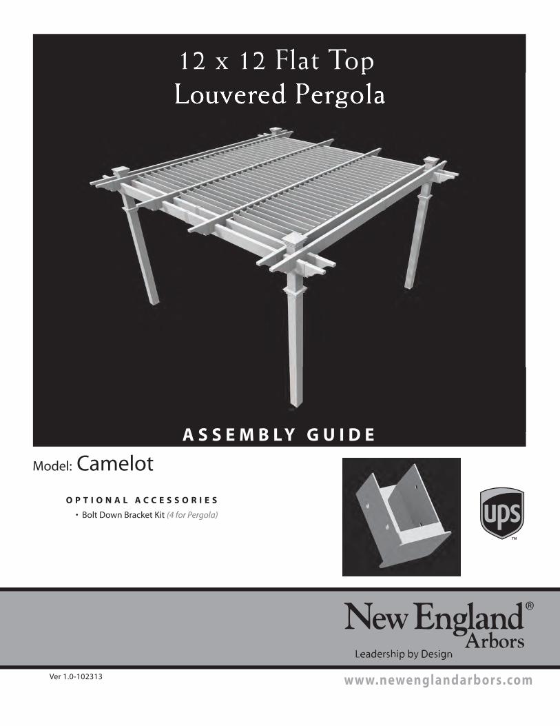
12 x 12 Flat Top
Louvered Pergola
A S S E M B L Y G U I D E
O P T I O N A L A C C E S S O R I E S
• Bolt Down Bracket Kit (4 for Pergola)
Ver 1.0-102313
Model: Camelot
www.newenglandarbors.com
A S S E M B L Y G U I D E
Ta b l e o f Co n t e n t s
2 12 x 12 Flat Top Louvered Pergola
3
12 x 12 Flat Top Louvered Pergola
Introduction & Overview……………………………. . . . . . . . . . . . . . . . . . . . . . . . . . . . . . . . . . . . . . . . . . . . . . . .………. . . . . .
Pergola Materials Overview………………………. . . . . . . . . . . . . . . . . . . . . . . . . . . …. . . . . . . . . . . . . . . . . . . . . . . . . . . . . . . . . . .
Pergola Materials Breakdown………………………. . . . . . . . . . . . . . . . . . . . . . . . . . . . . . . . . . . . .…. . . . . . . . . . . . . . . . . . . . . . .
Pergola Additional Materials List………………………………. . . . . . . . . . . . . . . . . . . . . . . . . . . . . . . . . . . . . . . . . . . . . . . . . .
Wood Post Layout & Installation for In-Ground Application………………………………. . . . . . . . . . . . . . . . . . . . .
Wood Post Layout & Installation using Bolt Down Post Brackets for Concrete or Wood Surface……………
Vinyl Column Assembly and Installation Over Wood Posts………………………. . . . . . . . . . ………………….
Vinyl Beam Assembly…………………………. . . . . . . . . . . . . . . . . . . . . . . . . . . . . . . . . . . . . . . . . . . . . . . . . . . . . . . . . . . . . . . . . . . . .
Vinyl Rafter Assembly……………………………………. . . . . . . . . . . . . . . . . . . . . . . . . . . . . . . . . . . . . . . . . . . . . . . . . . . . . . . . . .
Vinyl Beams & Rafter Placement……………………………………. . . . . . . . . . . . . . . . . . . . . . . . . . . . . . . . . . . . . . . . . . . . . .
Louver Assembly …………………………………………………………. . . . . . . . . . . . . . . . . . . . . . . . . . . . . . . . . . . . . . .
Turn Bar Holder Installation . . . . . . . .………………………………………. . . . . . . . . . . . . . . . . . . . . . . . . . . . . . . . . . . . . . .
Operations …………………. . . . . . . ……………………………………… . . . . . . . . . . . . . . . . . . . . . . . . . . . . . . . . . . . . . . .
Modification …………………………………………………………. . . . . . . . . . . . . . . . . . . . . . . . . . . . . . . . . . . . . . . . . . . . .
PAGE
4
5
6
7
8
9
10
11
13
15
www.newenglandarbors.com
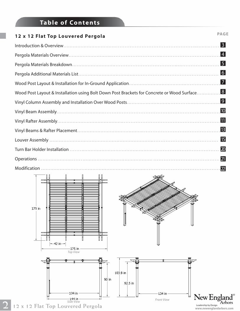
Top View
Front ViewSide View
21
20
22
� � � �� � � � �� � � � �� � � �
� � � �� � � �
� � � � � � � � �� � � � � �
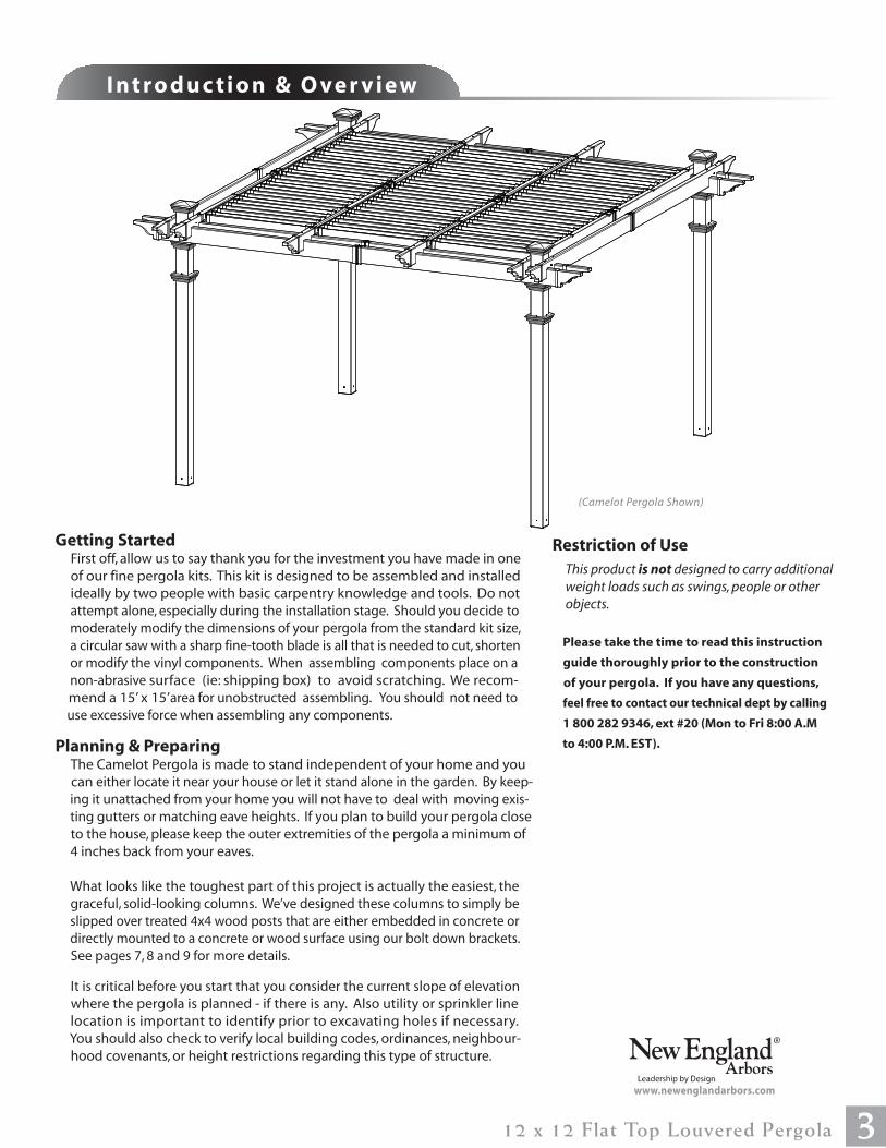
I n t r o d u c t i o n & O ve r v i e w
312 x 12 Flat Top Louvered Pergola
Getting Started First off, allow us to say thank you for the investment you have made in one
of our fine pergola kits. This kit is designed to be assembled and installed
ideally by two people with basic carpentry knowledge and tools. Do not
attempt alone, especially during the installation stage. Should you decide to
moderately modify the dimensions of your pergola from the standard kit size,
a circular saw with a sharp fine-tooth blade is all that is needed to cut, shorten
or modify the vinyl components. When assembling components place on a
non-abrasive surface (ie: shipping box) to avoid scratching. We recom-
mend a 15’ x 15’area for unobstructed assembling. You should not need to
use excessive force when assembling any components.
Planning & Preparing The Camelot Pergola is made to stand independent of your home and you
can either locate it near your house or let it stand alone in the garden. By keep-
ing it unattached from your home you will not have to deal with moving exis-
ting gutters or matching eave heights. If you plan to build your pergola close
to the house, please keep the outer extremities of the pergola a minimum of
4 inches back from your eaves.
What looks like the toughest part of this project is actually the easiest, the
graceful, solid-looking columns. We’ve designed these columns to simply be
slipped over treated 4x4 wood posts that are either embedded in concrete or
directly mounted to a concrete or wood surface using our bolt down brackets.
See pages 7, 8 and 9 for more details.
It is critical before you start that you consider the current slope of elevation
where the pergola is planned - if there is any. Also utility or sprinkler line
location is important to identify prior to excavating holes if necessary.
You should also check to verify local building codes, ordinances, neighbour-
hood covenants, or height restrictions regarding this type of structure.
Restriction of Use
This product is not designed to carry additional
weight loads such as swings, people or other
objects.
Please take the time to read this instruction
guide thoroughly prior to the construction
of your pergola. If you have any questions,
feel free to contact our technical dept by calling
1 800 282 9346, ext #20 (Mon to Fri 8:00 A.M
to 4:00 P.M. EST).
(Camelot Pergola Shown)
www.newenglandarbors.com
I n t r o d u c t i o n & O ve r v i e w
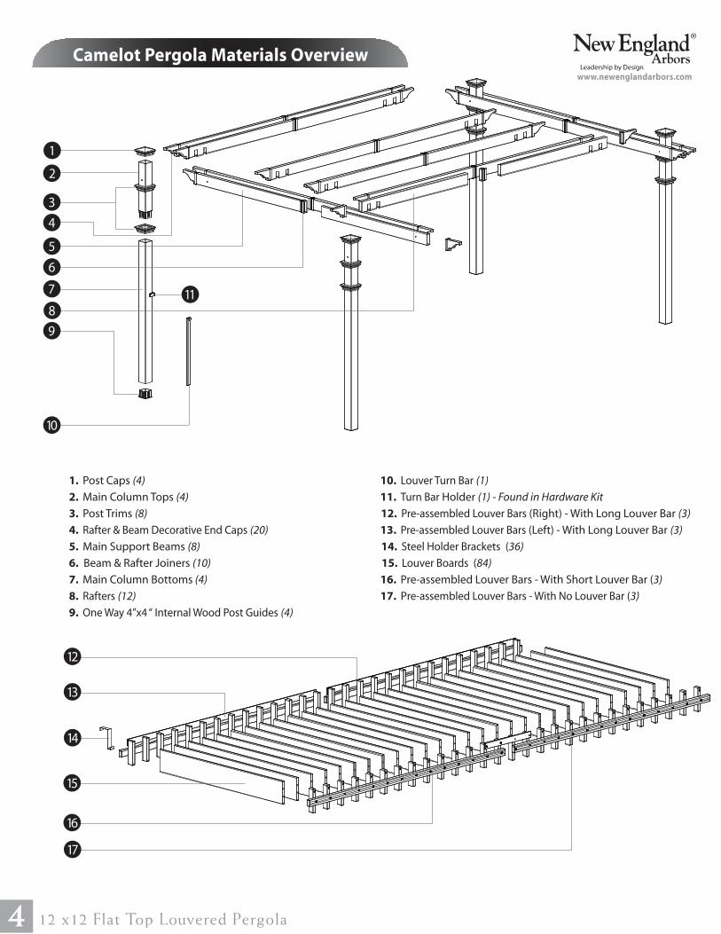
Camelot Pergola Materials Overview
4 12 x12 Flat Top Louvered Pergola
1
2
4
3
1. Post Caps (4)
2. Main Column Tops (4)
3. Post Trims (8)
4. Rafter & Beam Decorative End Caps (20)
5. Main Support Beams (8)
6. Beam & Rafter Joiners (10)
7. Main Column Bottoms (4)
8. Rafters (12)
9. One Way 4”x4 “ Internal Wood Post Guides (4)
5
7
8
6
www.newenglandarbors.com
14
17
16
12
15
9
10. Louver Turn Bar (1)
11. Turn Bar Holder (1) - Found in Hardware Kit
12. Pre-assembled Louver Bars (Right) - With Long Louver Bar (3)
13. Pre-assembled Louver Bars (Left) - With Long Louver Bar (3)
14. Steel Holder Brackets (36)
15. Louver Boards (84)
16. Pre-assembled Louver Bars - With Short Louver Bar (3)
17. Pre-assembled Louver Bars - With No Louver Bar (3)
10
11
13
11
76
2 9
16
3
10
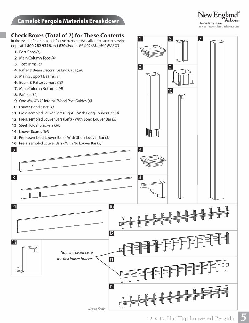
Check Boxes (Total of 7) for These Contents In the event of missing or defective parts please call our customer service
dept. at 1 800 282 9346, ext #20 (Mon. to Fri. 8:00 AM to 4:00 PM EST).
1. Post Caps (4)
2. Main Column Tops (4)
3. Post Trims (8)
4. Rafter & Beam Decorative End Caps (20)
5. Main Support Beams (8)
6. Beam & Rafter Joiners (10)
7. Main Column Bottoms (4)
8. Rafters (12)
9. One Way 4”x4 “ Internal Wood Post Guides (4)
10. Louver Handle Bar (1)
11. Pre-assembled Louver Bars (Right) - With Long Louver Bar (3)
12. Pre-assembled Louver Bars (Left) - With Long Louver Bar (3)
13. Steel Holder Brackets (36)
14. Louver Boards (84)
15. Pre-assembled Louver Bars - With Short Louver Bar (3)
16. Pre-assembled Louver Bars - With No Louver Bar (3)
Camelot Pergola Materials Breakdown
512 x 12 Flat Top Louvered Pergola
1
8 4
5
15
www.newenglandarbors.com
12
14
13
Not to Scale
Note the distance to
the first louver bracket
Pergola Additional Materials List
Hardware (in plastic bag)
NOTE: WE HAVE INCLUDED 10% EXTRA SCREWS
BEYOND WHAT IS IDENTIFIED BELOW.
All Screws Included with this Kit are Self-Auguring.
A. Tube of Vinyl Weld Glue (2)
B. 5/8” Self-Auguring Stainless Steel Screws (72)
(to lock Louver Assembly to Steel Holder Brackets )
C. 1 1/2” Self-Auguring Stainless Steel Screws (40) (for Beam and Rafter Joiners)
D. 2 1/2” Self-Auguring Stainless Steel Screws (32) (to lock the Main Column Bottom
and Tops to the Wood Posts )
E. 2 1/2“ Self-Auguring Stainless Steel Screws (2) (to fasten Turn Bar Holder to post)
F. 4“ Self-Auguring Stainless Steel Screws (32) (to lock Beams to the Posts)
G. 4” Self-Auguring Stainless Steel Screws (40) (to lock Rafters to the Beams)
H. 9” Stainless Steel Bolt Assembly with Nuts and Washers (4)
(to lock the Column Tops and Beams together)
I. Turn Bar Holder (1)
Extra Materials You will Need(Purchase separately from www.newenglandarbors.com or retailer of our products)
If Mounting Pergola on Concrete or Wood Deck
J. 4x4x8 Pressure-Treated Wood Posts (4) (purchase at local building center)
K. 4x4 Bolt Down Bracket Kit (purchase from www.newenglandarbors.com or a
retailer of our products)
1/4” x 2 3/4” Concrete Screws (12)
3/16” Concrete Drill bit. Min 3” long (1)
If Mounting Pergola in Ground
L. 4x4x12 Pressure-Treated Wood Posts (4) (purchase at local building center)
M. Concrete Ready Mix (4) (purchase at local building center)
Rafter/ Beam Support (Required)
N. 2x6x12Pressure-Treated Boards for Beams and Rafters (10) (purchase at
local building center)
Tools You Will Need • Level
• Rubber Mallet / Hammer
• Tape Measure
• String Line
• Wood Stakes (4) (temporary support for
string line)
• Step Ladders (2)
• Cordless Drill
• 1/2” Wood Drill Bit
• Circular Saw with Fine Tooth Blade
• Framing Level
• Framing Square
• Wrench / Socket Set Not to Scale
6 12 x 12 Flat Top Louvered Pergola
NJ L
Purchase
Separately
Purchase
Separately
Purchase
Separately
M
CONCRETE - Ready Mix
Purchase Separately
Purchase Separately
K
www.newenglandarbors.com
C D E GFB HA
I
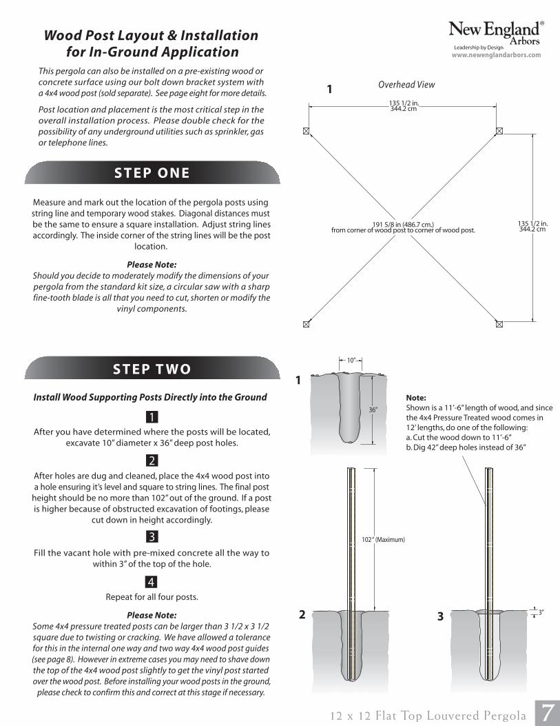
Wood Post Layout & Installation
for In-Ground Application
Measure and mark out the location of the pergola posts using
string line and temporary wood stakes. Diagonal distances must
be the same to ensure a square installation. Adjust string lines
accordingly. The inside corner of the string lines will be the post
location.
Please Note:
Should you decide to moderately modify the dimensions of your
pergola from the standard kit size, a circular saw with a sharp
fine-tooth blade is all that you need to cut, shorten or modify the
vinyl components.
1
This pergola can also be installed on a pre-existing wood or
concrete surface using our bolt down bracket system with
a 4x4 wood post (sold separate). See page eight for more details.
Post location and placement is the most critical step in the
overall installation process. Please double check for the
possibility of any underground utilities such as sprinkler, gas
or telephone lines.
S T E P O N E
After you have determined where the posts will be located,
excavate 10” diameter x 36” deep post holes.
After holes are dug and cleaned, place the 4x4 wood post into
a hole ensuring it’s level and square to string lines. The final post
height should be no more than 102” out of the ground. If a post
is higher because of obstructed excavation of footings, please
cut down in height accordingly.
Fill the vacant hole with pre-mixed concrete all the way to
within 3” of the top of the hole.
Repeat for all four posts.
Please Note:
Some 4x4 pressure treated posts can be larger than 3 1/2 x 3 1/2
square due to twisting or cracking. We have allowed a tolerance
for this in the internal one way and two way 4x4 wood post guides
(see page 8). However in extreme cases you may need to shave down
the top of the 4x4 wood post slightly to get the vinyl post started
over the wood post. Before installing your wood posts in the ground,
please check to confirm this and correct at this stage if necessary.
1
2
3
S T E P T W O
Install Wood Supporting Posts Directly into the Ground
4
135 1/2 in.344.2 cm
10”
36”
1
2 3” 3
712 x 12 Flat Top Louvered Pergola
Overhead View
191 5/8 in (486.7 cm.)from corner of wood post to corner of wood post.
102 “ (Maximum)
Note:
Shown is a 11’-6” length of wood, and since
the 4x4 Pressure Treated wood comes in
12’ lengths, do one of the following:
a. Cut the wood down to 11’-6”
b. Dig 42” deep holes instead of 36”
135 1/2 in.344.2 cm
www.newenglandarbors.com
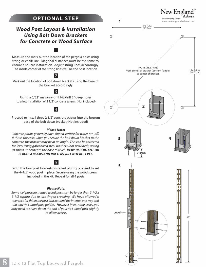
Wood Post Layout & Installation
Using Bolt Down Brackets
for Concrete or Wood Surface
Measure and mark out the location of the pergola posts using
string or chalk line. Diagonal distances must be the same to
ensure a square installation. Adjust string lines accordingly.
The inside corner of the string lines will be the post location.
Mark out the location of bolt down brackets using the base of
the bracket accordingly.
Using a 5/32” masonry drill bit, drill 3“ deep holes
to allow installation of 2 1/2” concrete screws. (Not included)
Proceed to install three 2 1/2” concrete screws into the bottom
base of the bolt down bracket.(Not included)
Please Note:
Concrete patios generally have sloped surface for water run-off.
If this is the case, when you secure the bolt down bracket to the
concrete, the bracket may be at an angle. This can be corrected
for level using galvanized steel washers (not provided), acting
as shims underneath the base to level - VERY IMPORTANT OR
PERGOLA BEAMS AND RAFTERS WILL NOT BE LEVEL.
1
1
O P T I O N A L S T E P
2
3
134 3/8in.341.3 cm.
134 3/8 in.341.3 cm.
2
3
With the four post brackets installed plumb, proceed to set
the 4x4x8’ wood post in place. Secure using the wood screws
included in the kit. Repeat for all 4 posts.
Please Note:
Some 4x4 pressure treated wood posts can be larger than 3 1/2 x
3 1/2 square due to twisting or cracking. We have allowed a
tolerance for this in the post brackets and the internal one way and
two way 4x4 wood post guides. However in extreme cases, you
may need to shave down the end of your 4x4 wood post slightly
to allow access.
55
96”
Level
4
4
Ma
rke
r
8 12 x 12 Flat Top Louvered Pergola
190 in. (482.7 cm.)
From corner of bracket (bottom flange),
to corner of bracket.
3“ (Deep)
www.newenglandarbors.com
Vinyl Column Assembly & Installation
Over Wood Posts
912 x 12 Flat Top Louvered Pergola
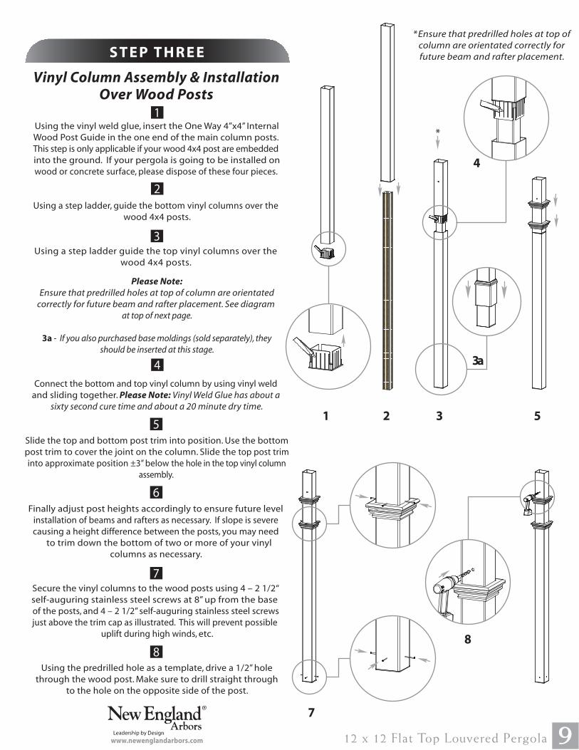
1
Using the vinyl weld glue, insert the One Way 4”x4” Internal
Wood Post Guide in the one end of the main column posts.
This step is only applicable if your wood 4x4 post are embedded
into the ground. If your pergola is going to be installed on
wood or concrete surface, please dispose of these four pieces.
Using a step ladder, guide the bottom vinyl columns over the
wood 4x4 posts.
Using a step ladder guide the top vinyl columns over the
wood 4x4 posts.
Please Note:
Ensure that predrilled holes at top of column are orientated
correctly for future beam and rafter placement. See diagram
at top of next page.
3a - If you also purchased base moldings (sold separately), they
should be inserted at this stage.
Connect the bottom and top vinyl column by using vinyl weld
and sliding together. Please Note: Vinyl Weld Glue has about a
sixty second cure time and about a 20 minute dry time.
Slide the top and bottom post trim into position. Use the bottom
post trim to cover the joint on the column. Slide the top post trim
into approximate position ±3” below the hole in the top vinyl column
assembly.
Finally adjust post heights accordingly to ensure future level
installation of beams and rafters as necessary. If slope is severe
causing a height difference between the posts, you may need
to trim down the bottom of two or more of your vinyl
columns as necessary.
Secure the vinyl columns to the wood posts using 4 – 2 1/2“
self-auguring stainless steel screws at 8” up from the base
of the posts, and 4 – 2 1/2” self-auguring stainless steel screws
just above the trim cap as illustrated. This will prevent possible
uplift during high winds, etc.
Using the predrilled hole as a template, drive a 1/2” hole
through the wood post. Make sure to drill straight through
to the hole on the opposite side of the post.
1
2
4
S T E P T H R E E
5
6
7
8
5
7
8
*Ensure that predrilled holes at top of
column are orientated correctly for
future beam and rafter placement.
3
3
*
www.newenglandarbors.com
2
4
3a
Vinyl Beam Assembly
1
1
2
S T E P F O U R
10 12 x 12 Flat Top Louvered Pergola
At this stage, the columns should be properly
installed as per the following illustration,
with the columns 134” in. (340.4 cm) apart.
Also, notice that the holes at the top of each
post should be facing the same direction.www.newenglandarbors.com
134in.340.4 cm.
134 in.340.4 cm.
Critical Note:
Note the location of the pre-drilled hole on beams as pictured
aside. These holes will align with the hole on the posts.
Both ends of beam section should extend approximately 6” over
the pressure treated wood.
Insert one 2x6x12’ pressure treated wood into a beam section
followed by the joiner and another beam section.
Glue and attach the Decorative End Caps onto the ends as shown.
1112 x 12 Flat Top louvered Pergola
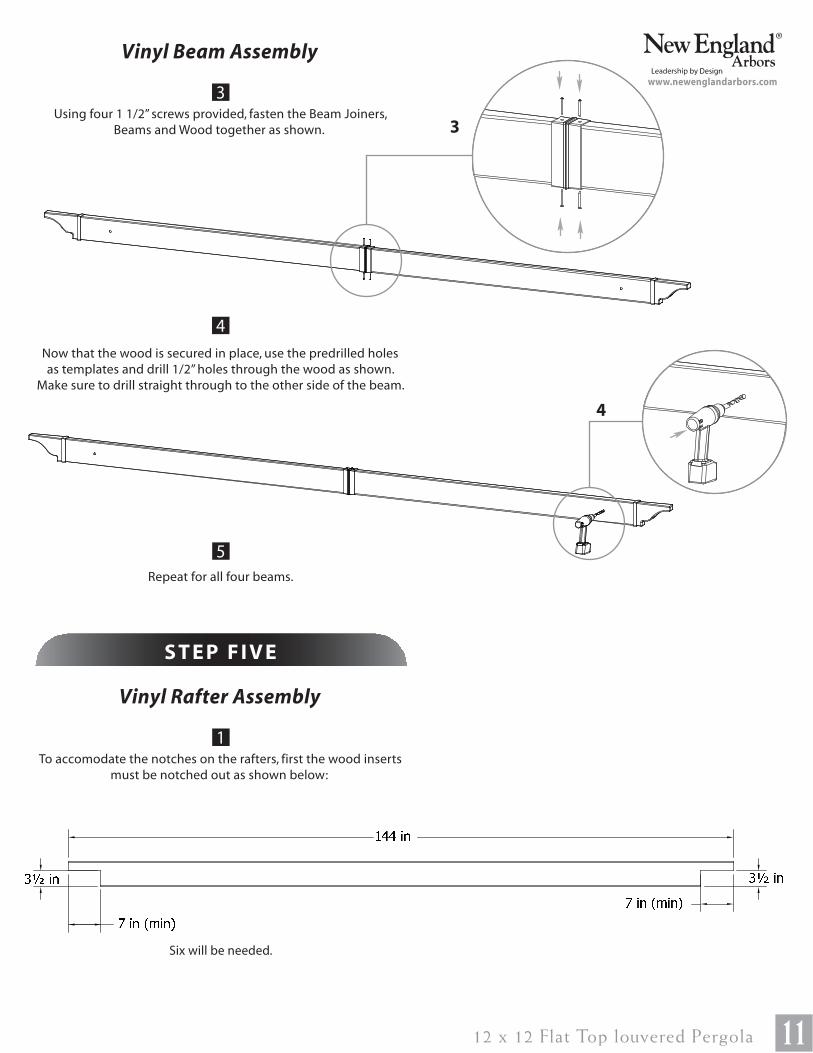
Vinyl Beam Assembly
Using four 1 1/2” screws provided, fasten the Beam Joiners,
Beams and Wood together as shown.
Now that the wood is secured in place, use the predrilled holes
as templates and drill 1/2” holes through the wood as shown.
Make sure to drill straight through to the other side of the beam.
Repeat for all four beams.
3
4
5
www.newenglandarbors.com
3
4
Vinyl Rafter Assembly
1
S T E P F I V E
To accomodate the notches on the rafters, first the wood inserts
must be notched out as shown below:
Six will be needed.
� � � � � � � � � � � �� � �� � � � � � � � � � � �
12 12 x 12 Flat Top louvered Pergola
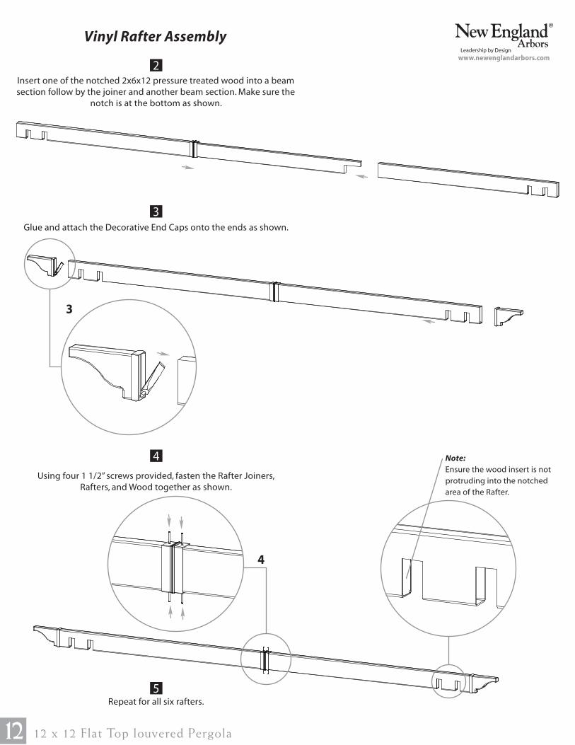
Vinyl Rafter Assembly
Insert one of the notched 2x6x12 pressure treated wood into a beam
section follow by the joiner and another beam section. Make sure the
notch is at the bottom as shown.
Glue and attach the Decorative End Caps onto the ends as shown.
Using four 1 1/2” screws provided, fasten the Rafter Joiners,
Rafters, and Wood together as shown.
Repeat for all six rafters.
2
3
4
5
www.newenglandarbors.com
3
4
Note:
Ensure the wood insert is not
protruding into the notched
area of the Rafter.
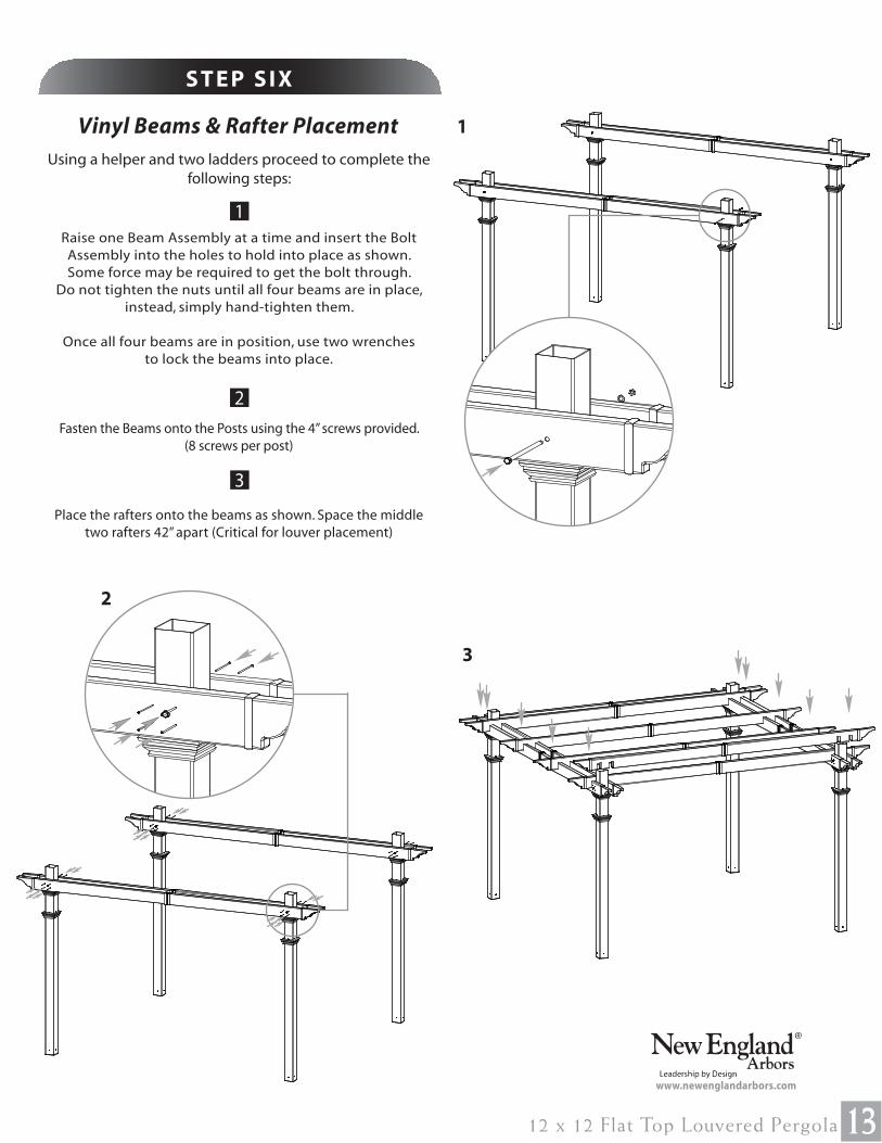
Vinyl Beams & Rafter Placement
1312 x 12 Flat Top Louvered Pergola
1
1
2
3
S T E P S I X
Using a helper and two ladders proceed to complete the
following steps:
Raise one Beam Assembly at a time and insert the Bolt
Assembly into the holes to hold into place as shown.
Some force may be required to get the bolt through.
Do not tighten the nuts until all four beams are in place,
instead, simply hand-tighten them.
Once all four beams are in position, use two wrenches
to lock the beams into place.
Fasten the Beams onto the Posts using the 4” screws provided.
(8 screws per post)
Place the rafters onto the beams as shown. Space the middle
two rafters 42” apart (Critical for louver placement)
2
3
www.newenglandarbors.com
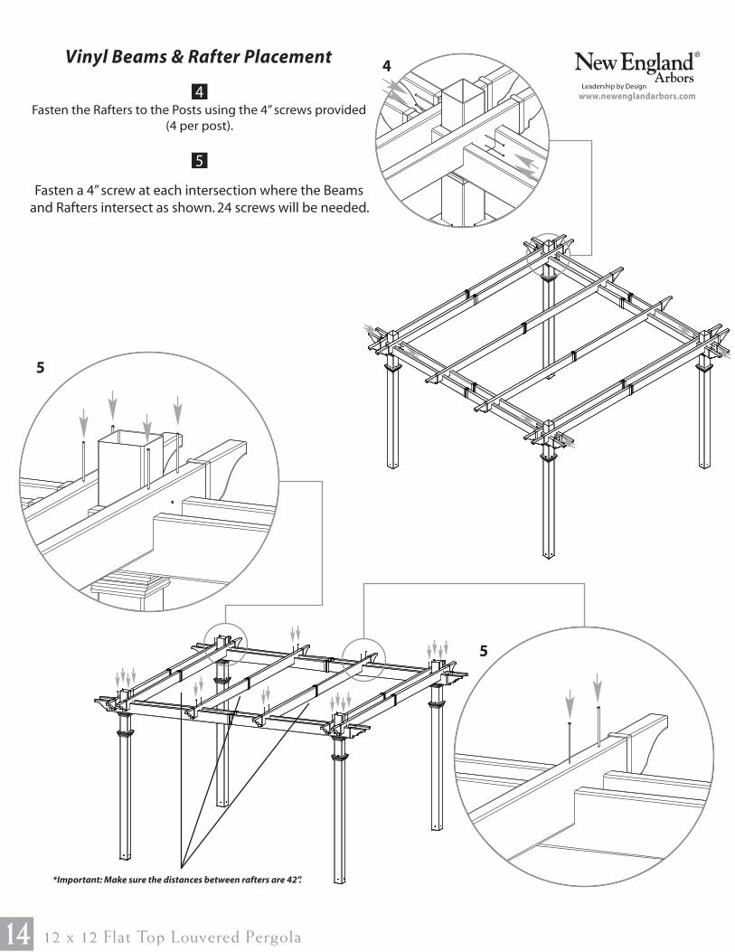
Vinyl Beams & Rafter Placement
14 12 x 12 Flat Top Louvered Pergola
Fasten the Rafters to the Posts using the 4” screws provided
(4 per post).
Fasten a 4” screw at each intersection where the Beams
and Rafters intersect as shown. 24 screws will be needed.
4
5
www.newenglandarbors.com
4
5
5
*Important: Make sure the distances between rafters are 42”.
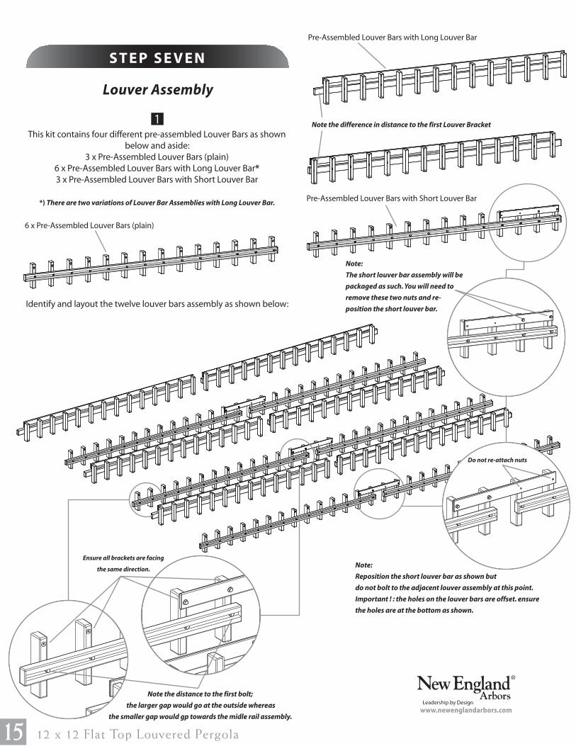
Louver Assembly
15 12 x 12 Flat Top Louvered Pergola
This kit contains four different pre-assembled Louver Bars as shown
below and aside:
3 x Pre-Assembled Louver Bars (plain)
6 x Pre-Assembled Louver Bars with Long Louver Bar*
3 x Pre-Assembled Louver Bars with Short Louver Bar
*) There are two variations of Louver Bar Assemblies with Long Louver Bar.
Identify and layout the twelve louver bars assembly as shown below:
1
S T E P S E V E N
6 x Pre-Assembled Louver Bars (plain)
Pre-Assembled Louver Bars with Long Louver Bar
Pre-Assembled Louver Bars with Short Louver Bar
Note:
The short louver bar assembly will be
packaged as such. You will need to
remove these two nuts and re-
position the short louver bar.
Note:
Reposition the short louver bar as shown but
do not bolt to the adjacent louver assembly at this point.
Important ! : the holes on the louver bars are offset. ensure
the holes are at the bottom as shown.
Note the distance to the first bolt;
the larger gap would go at the outside whereas
the smaller gap would gp towards the midle rail assembly. www.newenglandarbors.com
Ensure all brackets are facing
the same direction.
Note the difference in distance to the first Louver Bracket
Do not re-attach nuts
3
16
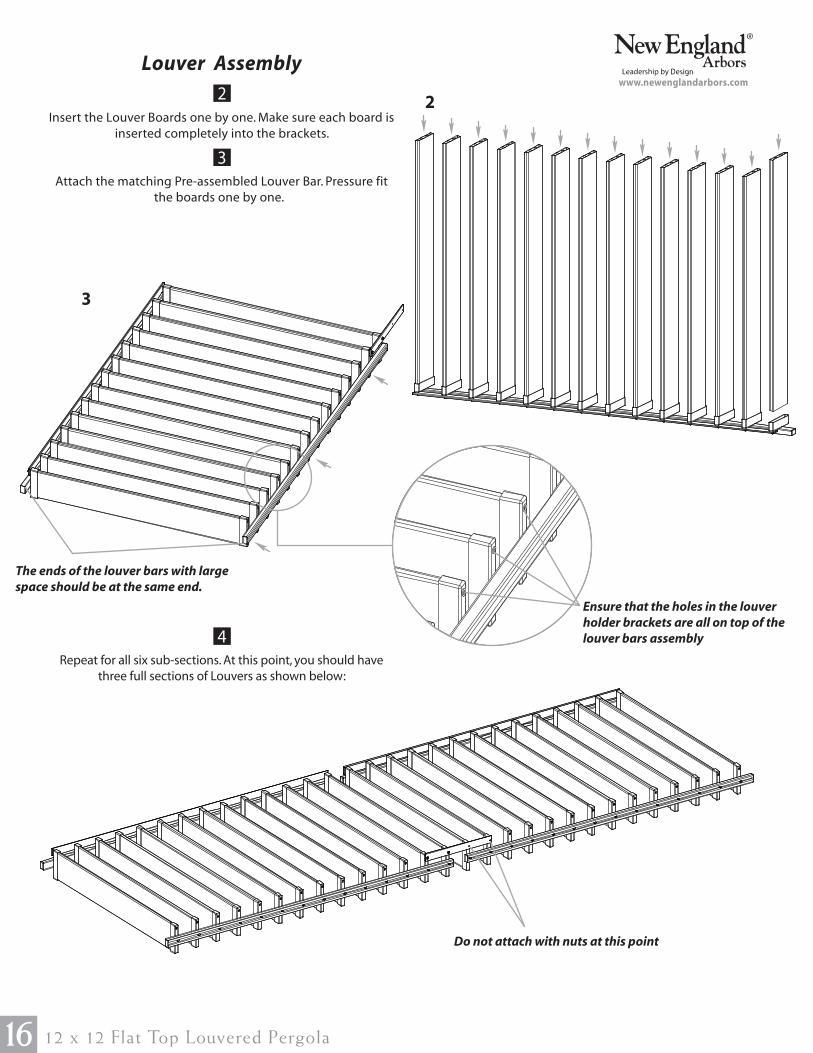
S T E P E I G H T
12 x 12 Flat Top Louvered Pergola
Insert the Louver Boards one by one. Make sure each board is
inserted completely into the brackets.
Attach the matching Pre-assembled Louver Bar. Pressure fit
the boards one by one.
Repeat for all six sub-sections. At this point, you should have
three full sections of Louvers as shown below:
Louver Assembly
2 2
www.newenglandarbors.com
3
The ends of the louver bars with large
space should be at the same end.
4
Do not attach with nuts at this point
Ensure that the holes in the louver
holder brackets are all on top of the
louver bars assembly
Louver Assembly
1712 x 12 Flat Top Louvered Pergola
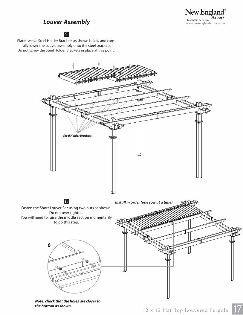
Place twelve Steel Holder Brackets as shown below and care-
fully lower the Louver assembly onto the steel brackets.
Do not screw the Steel Holder Brackets in place at this point.
Fasten the Short Louver Bar using two nuts as shown.
Do not over tighten.
You will need to raise the middle section momentarily
to do this step.
5
www.newenglandarbors.com
Steel Holder Brackets
6
6
Note: check that the holes are closer to
the bottom as shown.
Install in order (one row at a time)
18 12 x 12 Flat Top Louvered Pergola
Slide the Steel Holder Brackets to a spot which will not
interfere with the operations of the louvers. ‘Open’ and
‘Close’ the louvers to test and make sure the steel
brackets are not constraining the operation.
From the top, fasten the steel brackets in place using
5/8” screws. A total of 12 screws will be needed.
Repeat for the underside of the steel brackets.
Another 12, 5/8” screws will be needed.
Louver Assembly
7
www.newenglandarbors.com
8
8
7
Bottom View
9
9
Louver Assembly
1912 x 12 Flat Top Louvered Pergola
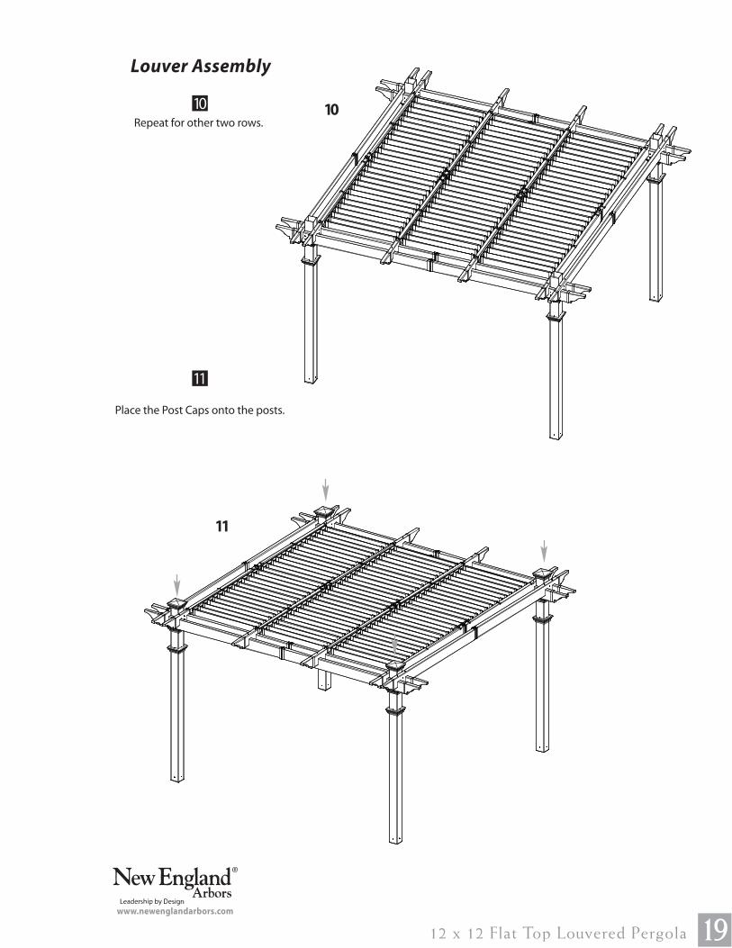
Repeat for other two rows.
Place the Post Caps onto the posts.
10
www.newenglandarbors.com
11
11
10
Turn Bar Holder Installation
1
1
2
S T E P E I G H T
20 12 x 12 Flat Top Louvered Pergola
www.newenglandarbors.com
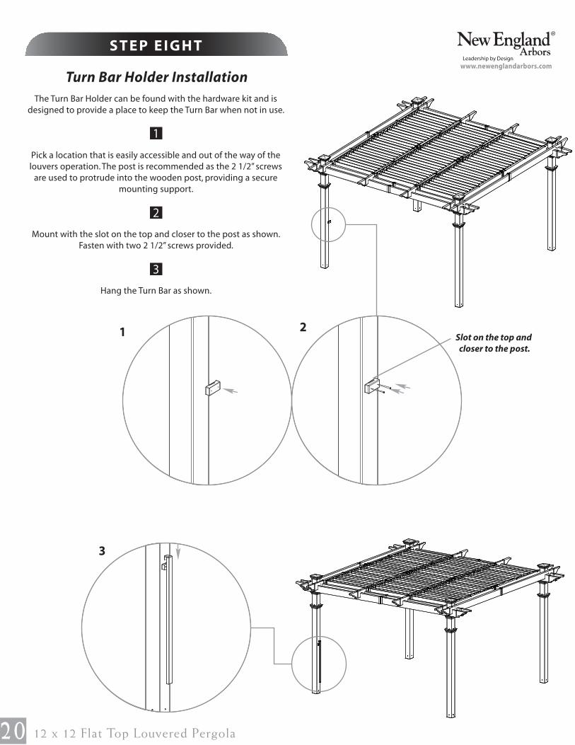
The Turn Bar Holder can be found with the hardware kit and is
designed to provide a place to keep the Turn Bar when not in use.
Pick a location that is easily accessible and out of the way of the
louvers operation. The post is recommended as the 2 1/2” screws
are used to protrude into the wooden post, providing a secure
mounting support.
Mount with the slot on the top and closer to the post as shown.
Fasten with two 2 1/2” screws provided.
Hang the Turn Bar as shown.
3
2Slot on the top and
closer to the post.
3
2112 x 12 Flat Top Louvered Pergola
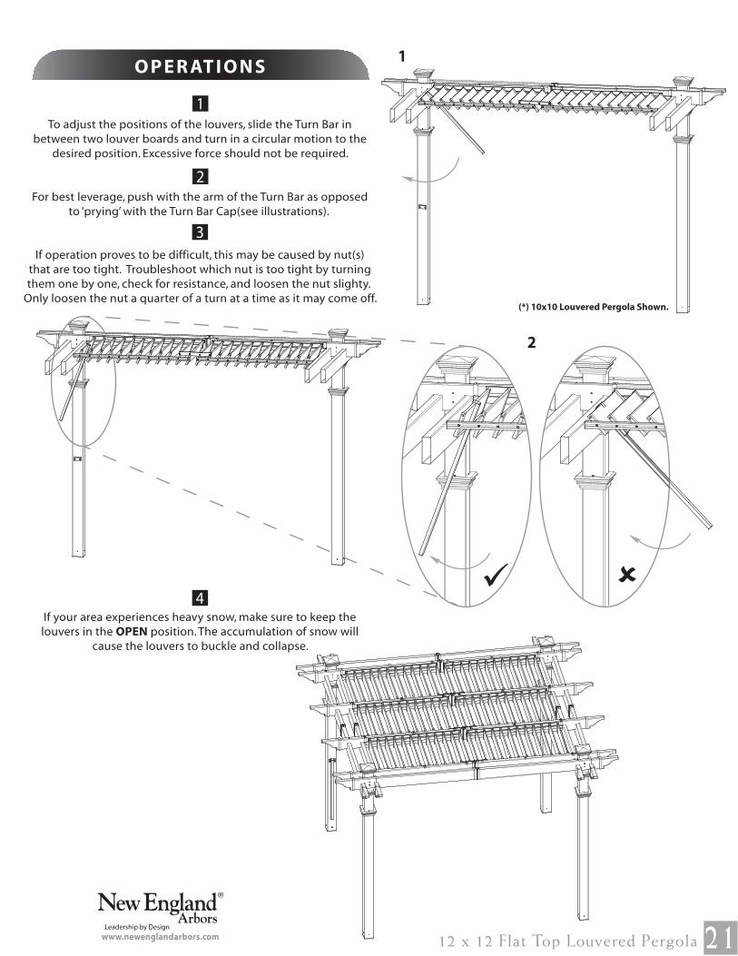
To adjust the positions of the louvers, slide the Turn Bar in
between two louver boards and turn in a circular motion to the
desired position. Excessive force should not be required.
For best leverage, push with the arm of the Turn Bar as opposed
to ‘prying’ with the Turn Bar Cap(see illustrations).
If operation proves to be difficult, this may be caused by nut(s)
that are too tight. Troubleshoot which nut is too tight by turning
them one by one, check for resistance, and loosen the nut slighty.
Only loosen the nut a quarter of a turn at a time as it may come off.
If your area experiences heavy snow, make sure to keep the
louvers in the OPEN position. The accumulation of snow will
cause the louvers to buckle and collapse.
1
2
O P E R AT I O N S
3
www.newenglandarbors.com
1
ûü
2
4
(*) 10x10 Louvered Pergola Shown.
1
2
M O D I F I C AT I O N
22 12 x 12 Flat Top Louvered Pergola
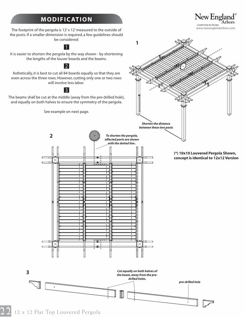
www.newenglandarbors.comThe footprint of the pergola is 12’ x 12’ measured to the outside of
the posts. If a smaller dimension is required, a few guidelines should
be considered:
It is easier to shorten the pergola by the way shown - by shortening
the lengths of the louver boards and the beams.
Asthetically, it is best to cut all 84 boards equally so that they are
even across the three rows. However, cutting only one or two rows
will involve less labor.
The beams shall be cut at the middle (away from the pre-drilled hole),
and equally on both halves to ensure the symmetry of the pergola.
See example on next page.
3
3
1
Shorten the distance
between these two posts
2 To shorten the pergola,
affected parts are shown
with the dotted line .
Cut equally on both halves of
the beam, away from the pre-
drilled holes.
pre-drilled hole
(*) 10x10 Louvered Pergola Shown,
concept is identical to 12x12 Version

2312 x 12 Flat Top Louvered Pergola
Below is an example of resizing the pergola:
[In this example, the new dimensions are 120” (10’) x 102” (8’-6”)]
M O D I F I C AT I O N S
www.newenglandarbors.com
28 in
120 in
(Distance to
outside posts)
102 in
(Distance to the outside posts)
28 in 28 in
All 72 louver boards are cut down by 6”
All 4 Beams are cut down by 9”
(*) 10x10 Louvered Pergola Shown,
concept is identical to 12x12 Version