120174253 twi radiographic interpretation weld defects repair
DESCRIPTION
120174253 TWI Radiographic Interpretation Weld Defects RepairTRANSCRIPT
M.S.Rogers Copyright © 2004 TWI Ltd
Weld Defects & Repairs
Radiographic Interpretation
M.S.Rogers Copyright © 2004 TWI Ltd
Faults in Fusion Welds
M.S.Rogers Copyright © 2004 TWI Ltd
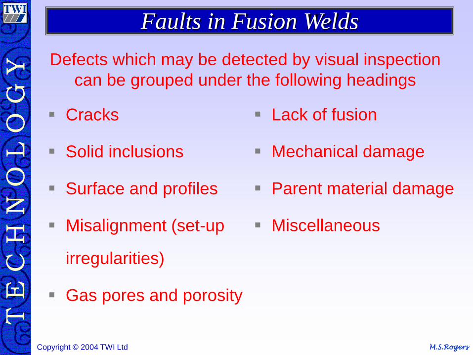
Defects which may be detected by visual inspection
can be grouped under the following headings
Cracks
Solid inclusions
Surface and profiles
Misalignment (set-up
irregularities)
Gas pores and porosity
Lack of fusion
Mechanical damage
Parent material damage
Miscellaneous
Faults in Fusion Welds
M.S.Rogers Copyright © 2004 TWI Ltd
Cracks
M.S.Rogers Copyright © 2004 TWI Ltd
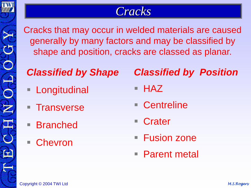
Classified by Shape
Longitudinal
Transverse
Branched
Chevron
Classified by Position
HAZ
Centreline
Crater
Fusion zone
Parent metal
Cracks that may occur in welded materials are caused
generally by many factors and may be classified by
shape and position, cracks are classed as planar.
Cracks
M.S.Rogers Copyright © 2004 TWI Ltd
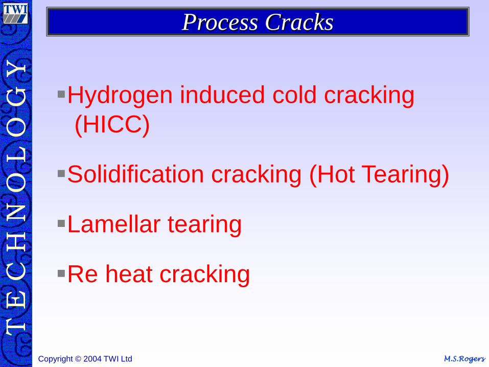
Hydrogen induced cold cracking
(HICC)
Solidification cracking (Hot Tearing)
Lamellar tearing
Re heat cracking
Process Cracks
M.S.Rogers Copyright © 2004 TWI Ltd
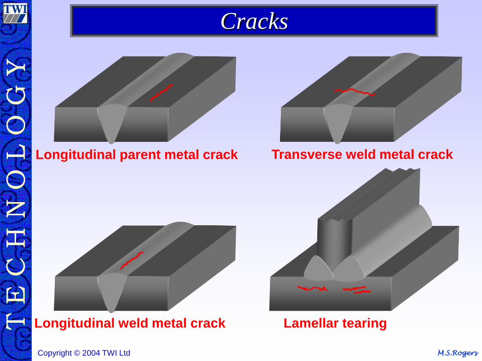
Longitudinal parent metal crack
Longitudinal weld metal crack Lamellar tearing
Transverse weld metal crack
Cracks
M.S.Rogers Copyright © 2004 TWI Ltd
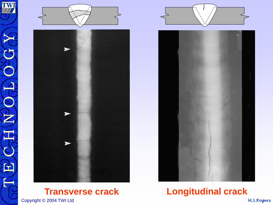
Transverse crack Longitudinal crack

M.S.Rogers Copyright © 2004 TWI Ltd
Inclusions
M.S.Rogers Copyright © 2004 TWI Ltd
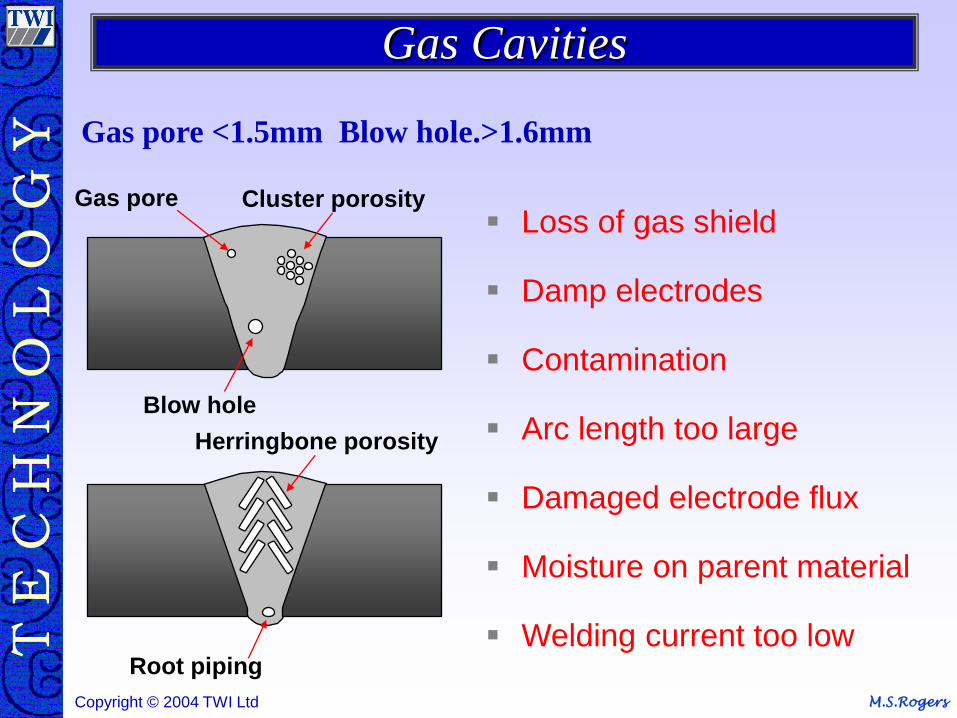
Root piping
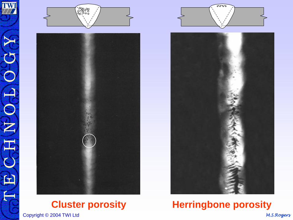
Cluster porosity Gas pore
Blow hole
Herringbone porosity
Loss of gas shield
Damp electrodes
Contamination
Arc length too large
Damaged electrode flux
Moisture on parent material
Welding current too low
Gas pore <1.5mm Blow hole.>1.6mm
Gas Cavities
M.S.Rogers Copyright © 2004 TWI Ltd
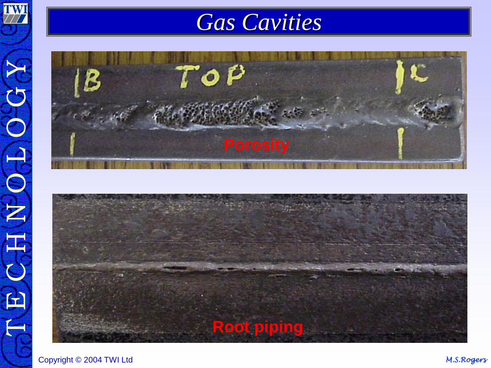
Root piping
Porosity
Gas Cavities
M.S.Rogers Copyright © 2004 TWI Ltd
Cluster porosity Herringbone porosity
M.S.Rogers Copyright © 2004 TWI Ltd
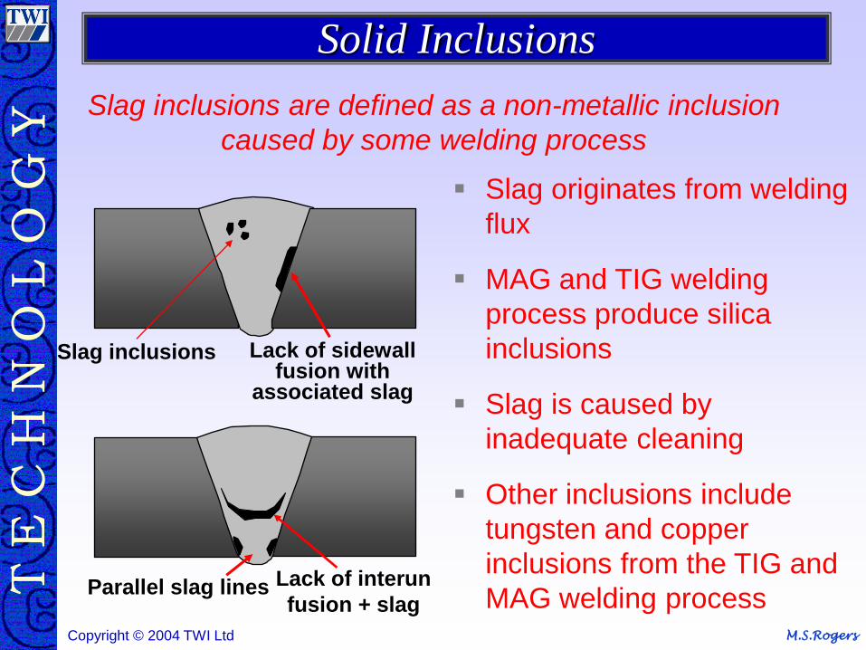
Slag originates from welding
flux
MAG and TIG welding
process produce silica
inclusions
Slag is caused by
inadequate cleaning
Other inclusions include
tungsten and copper
inclusions from the TIG and
MAG welding process
Slag inclusions are defined as a non-metallic inclusion
caused by some welding process
Slag inclusions
Parallel slag lines Lack of interun
fusion + slag
Lack of sidewall fusion with
associated slag
Solid Inclusions
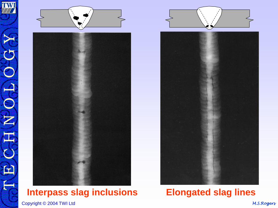
M.S.Rogers Copyright © 2004 TWI Ltd
Elongated slag lines Interpass slag inclusions
M.S.Rogers Copyright © 2004 TWI Ltd
Lack of Fusion
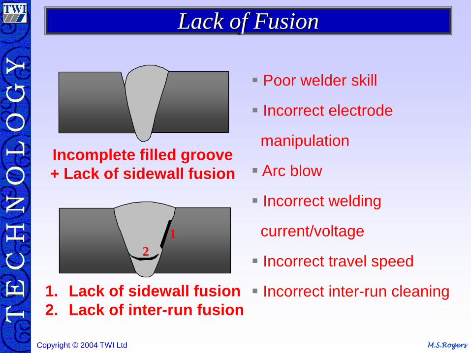
M.S.Rogers Copyright © 2004 TWI Ltd
Incomplete filled groove
+ Lack of sidewall fusion
1
2
1. Lack of sidewall fusion
2. Lack of inter-run fusion
Poor welder skill
Incorrect electrode
manipulation
Arc blow
Incorrect welding
current/voltage
Incorrect travel speed
Incorrect inter-run cleaning
Lack of Fusion
M.S.Rogers Copyright © 2004 TWI Ltd
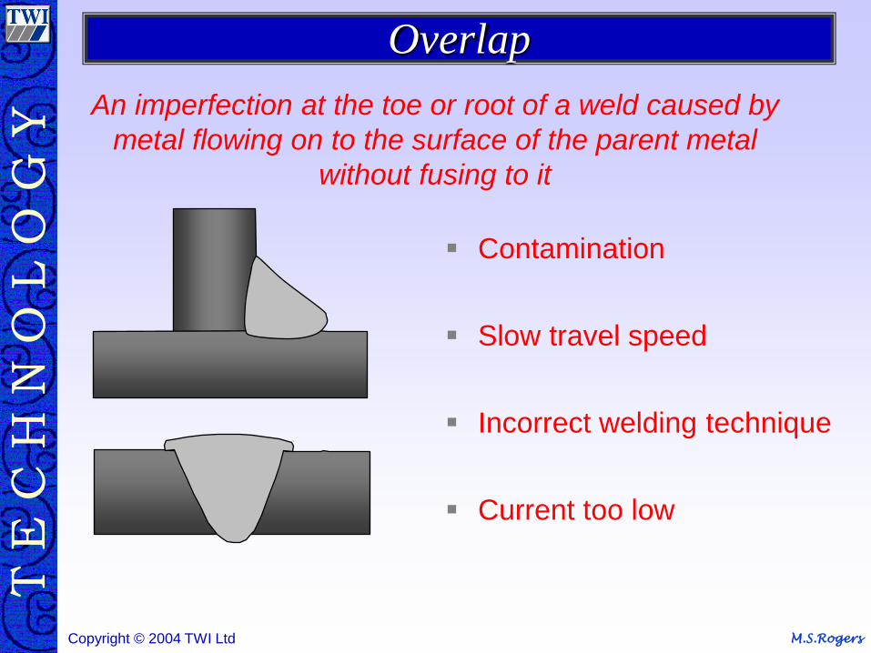
An imperfection at the toe or root of a weld caused by
metal flowing on to the surface of the parent metal
without fusing to it
Contamination
Slow travel speed
Incorrect welding technique
Current too low
Overlap
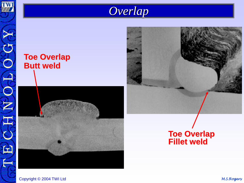
M.S.Rogers Copyright © 2004 TWI Ltd
Toe Overlap Fillet weld
Toe Overlap Butt weld
Overlap
M.S.Rogers Copyright © 2004 TWI Ltd
Incomplete root fusion
Incomplete root penetration
Low Amps/volts
Large Root face
Small Root Gap
Fast Travel Speed
Incorrect Electrode Angle
Contamination
Arc blow
Weld Root Defects
M.S.Rogers Copyright © 2004 TWI Ltd
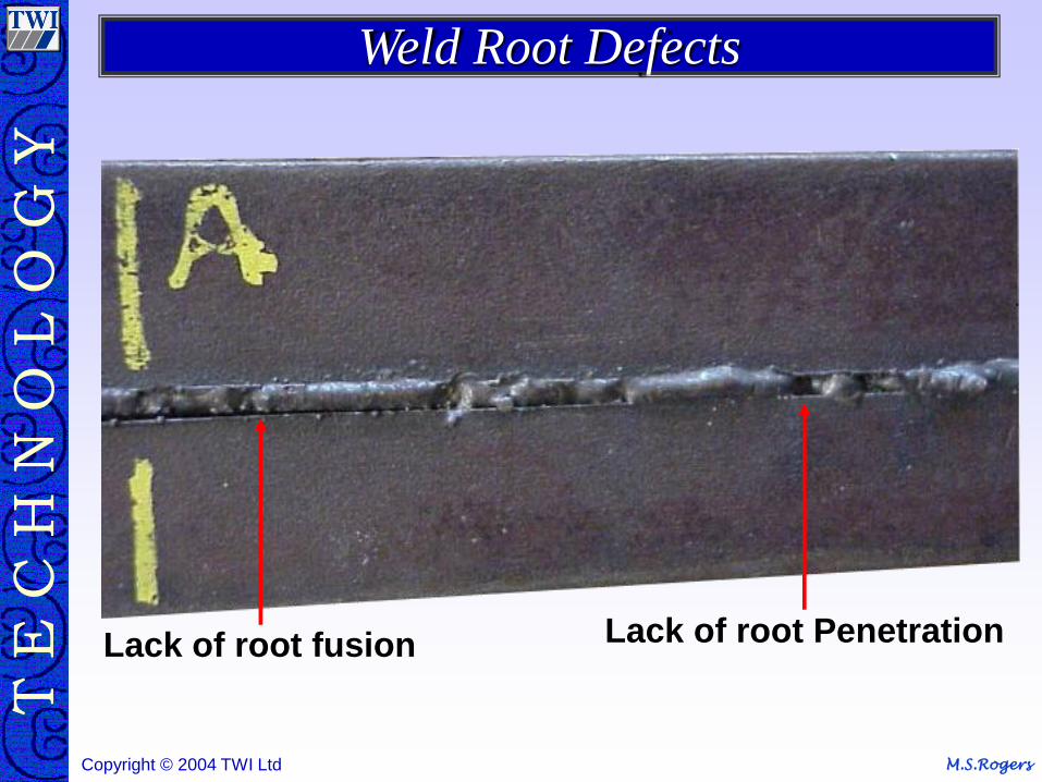
Lack of root fusion Lack of root Penetration
Weld Root Defects
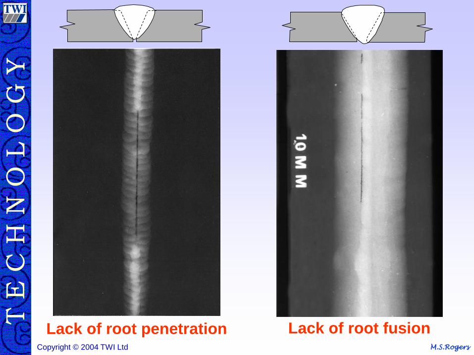
M.S.Rogers Copyright © 2004 TWI Ltd
Lack of root penetration Lack of root fusion
M.S.Rogers Copyright © 2004 TWI Ltd
Surface & Profile
M.S.Rogers Copyright © 2004 TWI Ltd
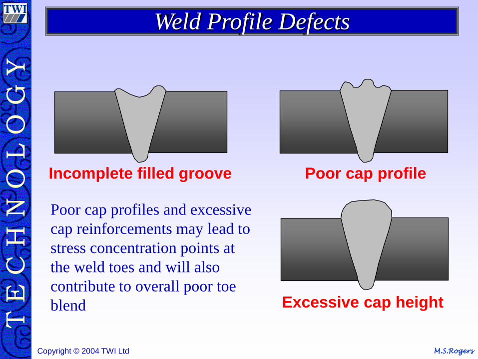
Incomplete filled groove Poor cap profile
Excessive cap height
Poor cap profiles and excessive
cap reinforcements may lead to
stress concentration points at
the weld toes and will also
contribute to overall poor toe
blend
Weld Profile Defects
M.S.Rogers Copyright © 2004 TWI Ltd
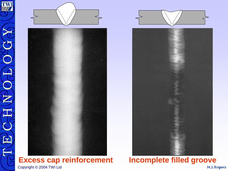
Incomplete filled groove Excess cap reinforcement
M.S.Rogers Copyright © 2004 TWI Ltd
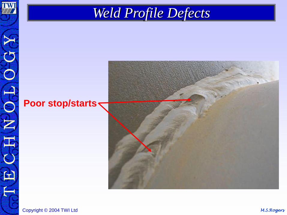
Poor stop/starts
Weld Profile Defects
M.S.Rogers Copyright © 2004 TWI Ltd
Miscellaneous Defects

M.S.Rogers Copyright © 2004 TWI Ltd
Spatter Excessive current
Damp electrodes
Contamination
Incorrect wire feed speed
when welding with the MAG
welding process
Arc blow
Miscellaneous Defects
M.S.Rogers Copyright © 2004 TWI Ltd
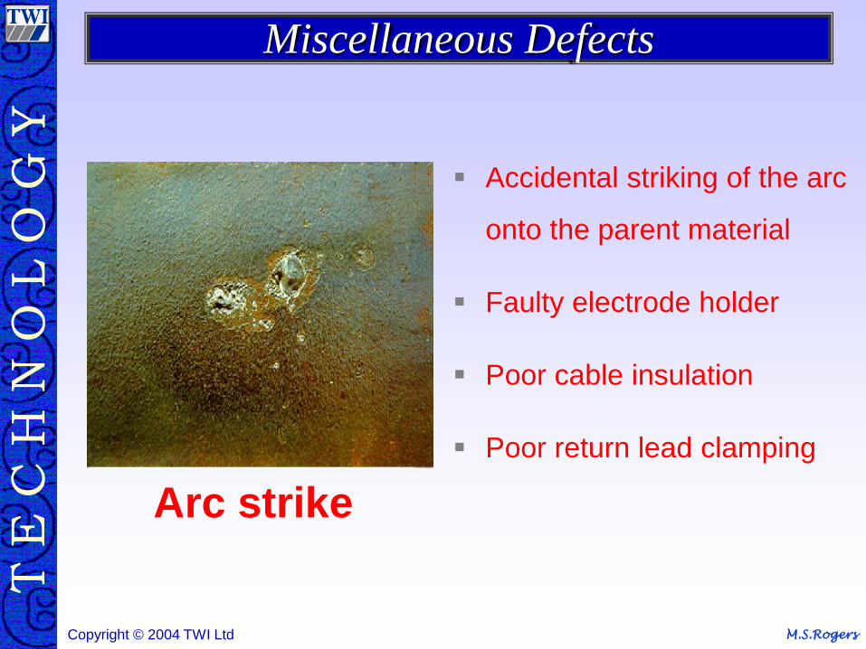
Accidental striking of the arc
onto the parent material
Faulty electrode holder
Poor cable insulation
Poor return lead clamping
Arc strike
Miscellaneous Defects
M.S.Rogers Copyright © 2004 TWI Ltd
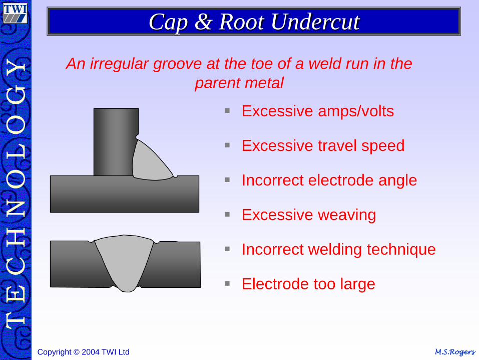
An irregular groove at the toe of a weld run in the
parent metal
Excessive amps/volts
Excessive travel speed
Incorrect electrode angle
Excessive weaving
Incorrect welding technique
Electrode too large
Cap & Root Undercut
M.S.Rogers Copyright © 2004 TWI Ltd
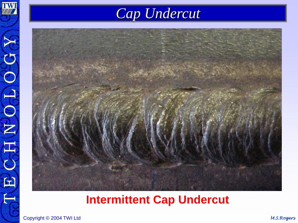
Intermittent Cap Undercut
Cap Undercut
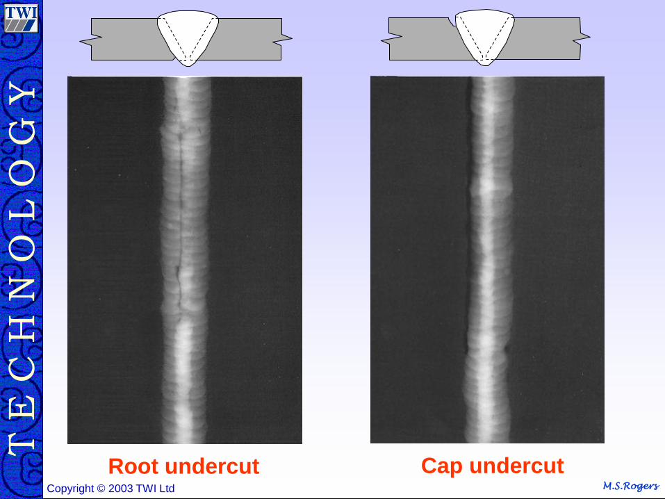
M.S.Rogers Copyright © 2004 TWI Ltd M.S.Rogers Copyright © 2003 TWI Ltd
Cap undercut Root undercut
M.S.Rogers Copyright © 2004 TWI Ltd
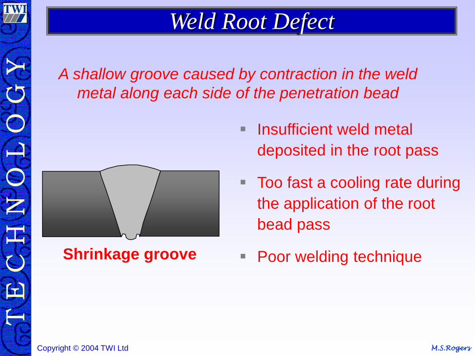
Shrinkage groove
Insufficient weld metal
deposited in the root pass
Too fast a cooling rate during
the application of the root
bead pass
Poor welding technique
A shallow groove caused by contraction in the weld
metal along each side of the penetration bead
Weld Root Defect
M.S.Rogers Copyright © 2004 TWI Ltd
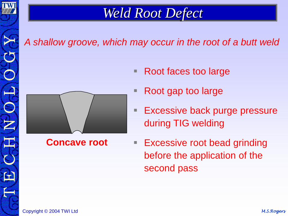
Concave root
Root faces too large
Root gap too large
Excessive back purge pressure
during TIG welding
Excessive root bead grinding
before the application of the
second pass
A shallow groove, which may occur in the root of a butt weld
Weld Root Defect
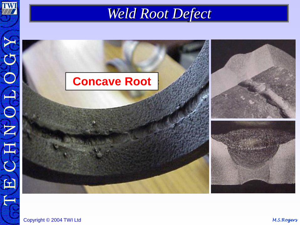
M.S.Rogers Copyright © 2004 TWI Ltd
Concave Root
Weld Root Defect
M.S.Rogers Copyright © 2004 TWI Ltd
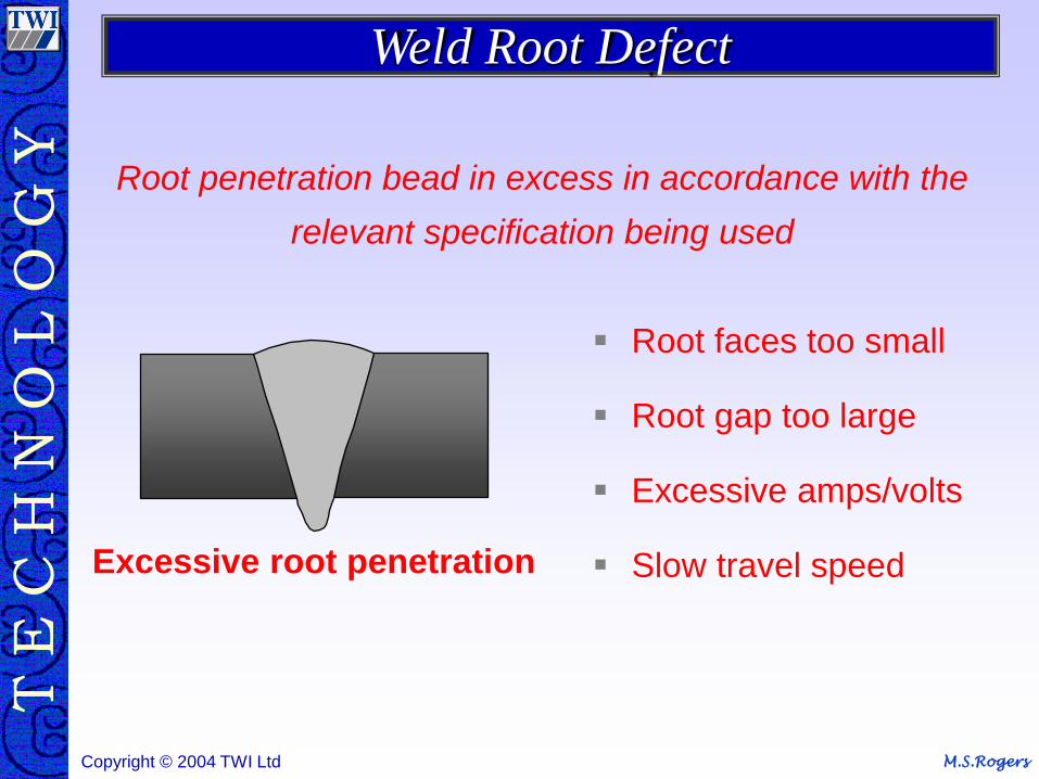
Excessive root penetration
Root faces too small
Root gap too large
Excessive amps/volts
Slow travel speed
Root penetration bead in excess in accordance with the
relevant specification being used
Weld Root Defect
M.S.Rogers Copyright © 2004 TWI Ltd
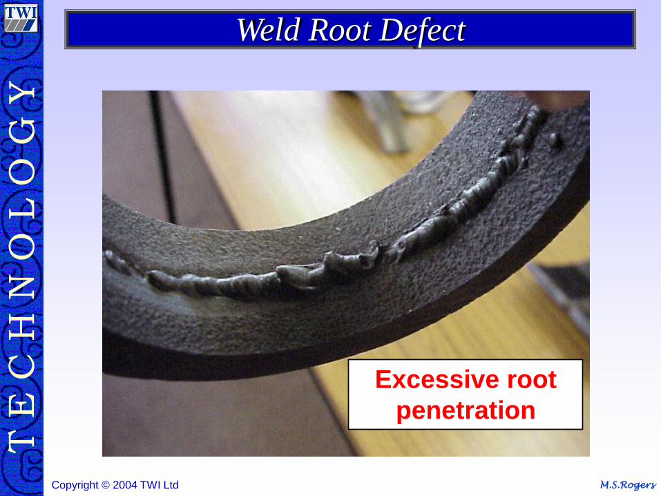
Weld Root Defect
Excessive root
penetration
M.S.Rogers Copyright © 2004 TWI Ltd M.S.Rogers Copyright © 2003 TWI Ltd
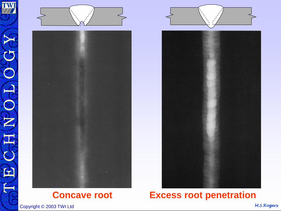
Concave root Excess root penetration
M.S.Rogers Copyright © 2004 TWI Ltd
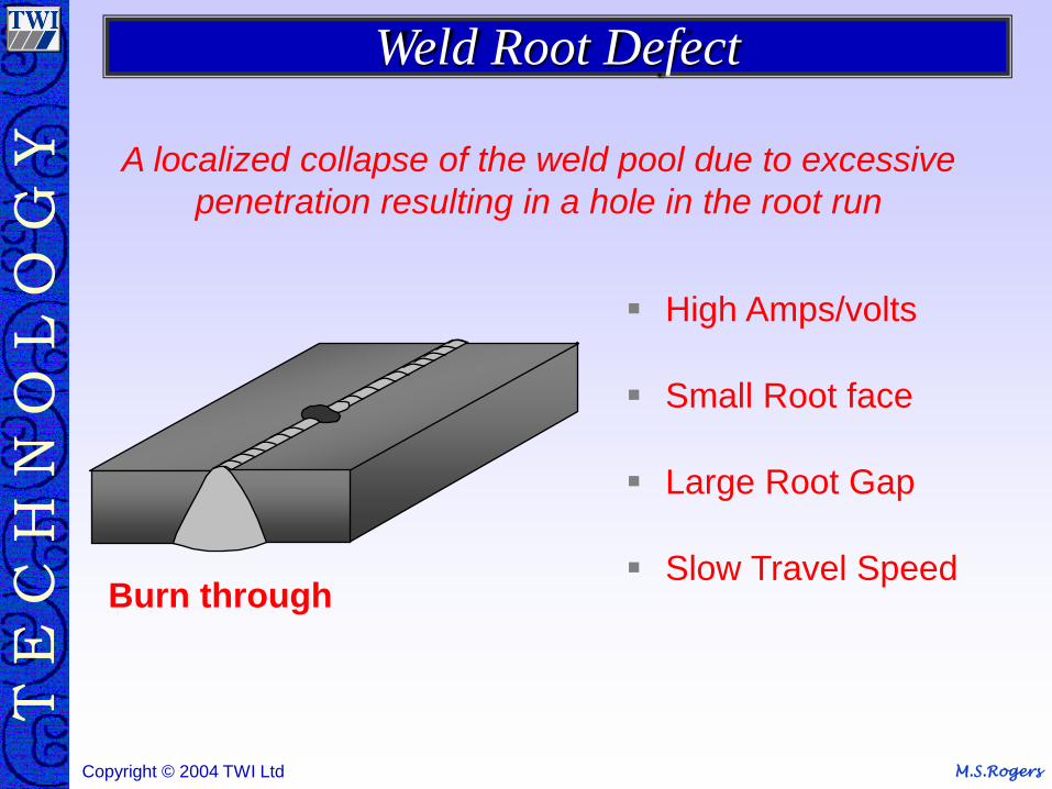
High Amps/volts
Small Root face
Large Root Gap
Slow Travel Speed Burn through
A localized collapse of the weld pool due to excessive
penetration resulting in a hole in the root run
Weld Root Defect
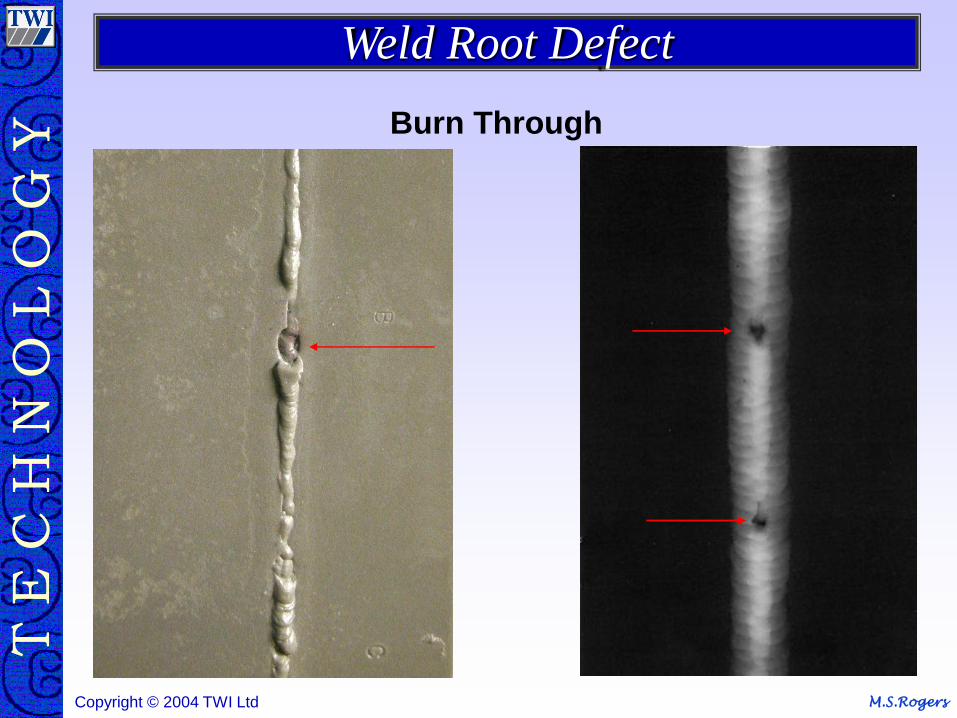
M.S.Rogers Copyright © 2004 TWI Ltd
Weld Root Defect
Burn Through
M.S.Rogers Copyright © 2004 TWI Ltd
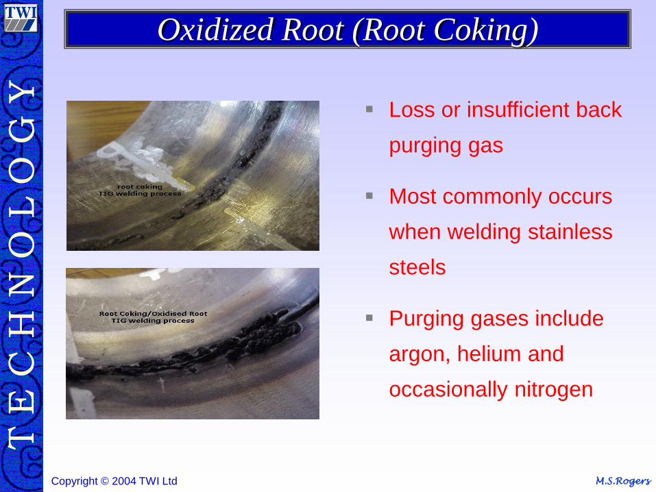
Loss or insufficient back
purging gas
Most commonly occurs
when welding stainless
steels
Purging gases include
argon, helium and
occasionally nitrogen
Oxidized Root (Root Coking)
M.S.Rogers Copyright © 2004 TWI Ltd
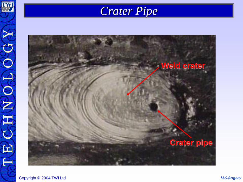
Crater pipe
Weld crater
Crater Pipe
M.S.Rogers Copyright © 2004 TWI Ltd
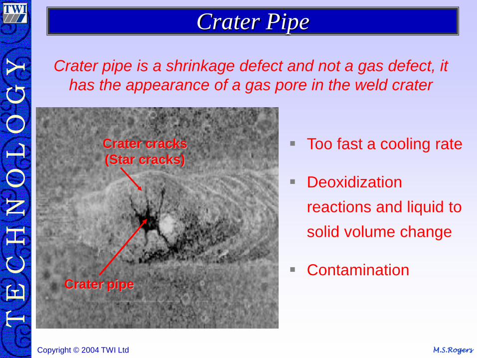
Crater pipe is a shrinkage defect and not a gas defect, it
has the appearance of a gas pore in the weld crater
Too fast a cooling rate
Deoxidization
reactions and liquid to
solid volume change
Contamination
Crater cracks
(Star cracks)
Crater pipe
Crater Pipe
M.S.Rogers Copyright © 2004 TWI Ltd
Mechanical Damage
M.S.Rogers Copyright © 2004 TWI Ltd
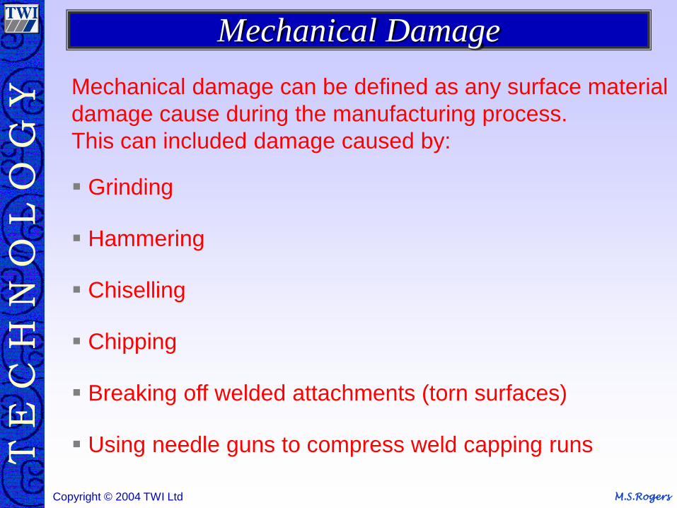
Mechanical damage can be defined as any surface material
damage cause during the manufacturing process.
This can included damage caused by:
Grinding
Hammering
Chiselling
Chipping
Breaking off welded attachments (torn surfaces)
Using needle guns to compress weld capping runs
Mechanical Damage
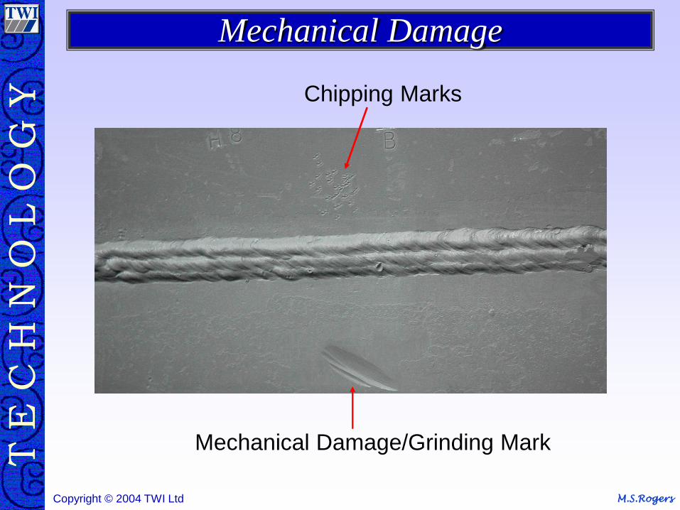
M.S.Rogers Copyright © 2004 TWI Ltd
Mechanical Damage
Mechanical Damage/Grinding Mark
Chipping Marks
M.S.Rogers Copyright © 2004 TWI Ltd
Set-up Irregularities
M.S.Rogers Copyright © 2004 TWI Ltd
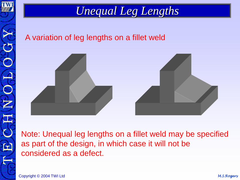
A variation of leg lengths on a fillet weld
Note: Unequal leg lengths on a fillet weld may be specified
as part of the design, in which case it will not be
considered as a defect.
Unequal Leg Lengths
M.S.Rogers Copyright © 2004 TWI Ltd
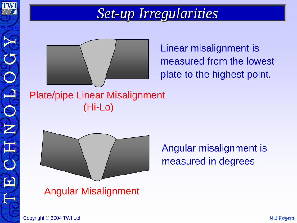
Plate/pipe Linear Misalignment
(Hi-Lo)
Angular Misalignment
Linear misalignment is
measured from the lowest
plate to the highest point.
Angular misalignment is
measured in degrees
Set-up Irregularities
M.S.Rogers Copyright © 2004 TWI Ltd
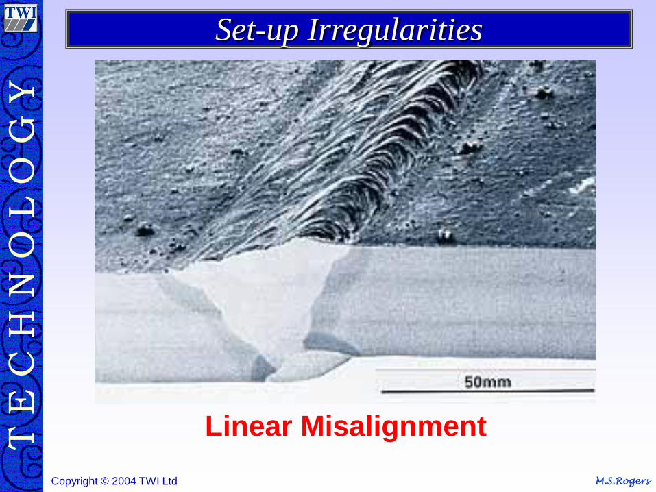
Linear Misalignment
Set-up Irregularities

M.S.Rogers Copyright © 2004 TWI Ltd
Linear Misalignment
Set-up Irregularities

M.S.Rogers Copyright © 2004 TWI Ltd
Any Questions
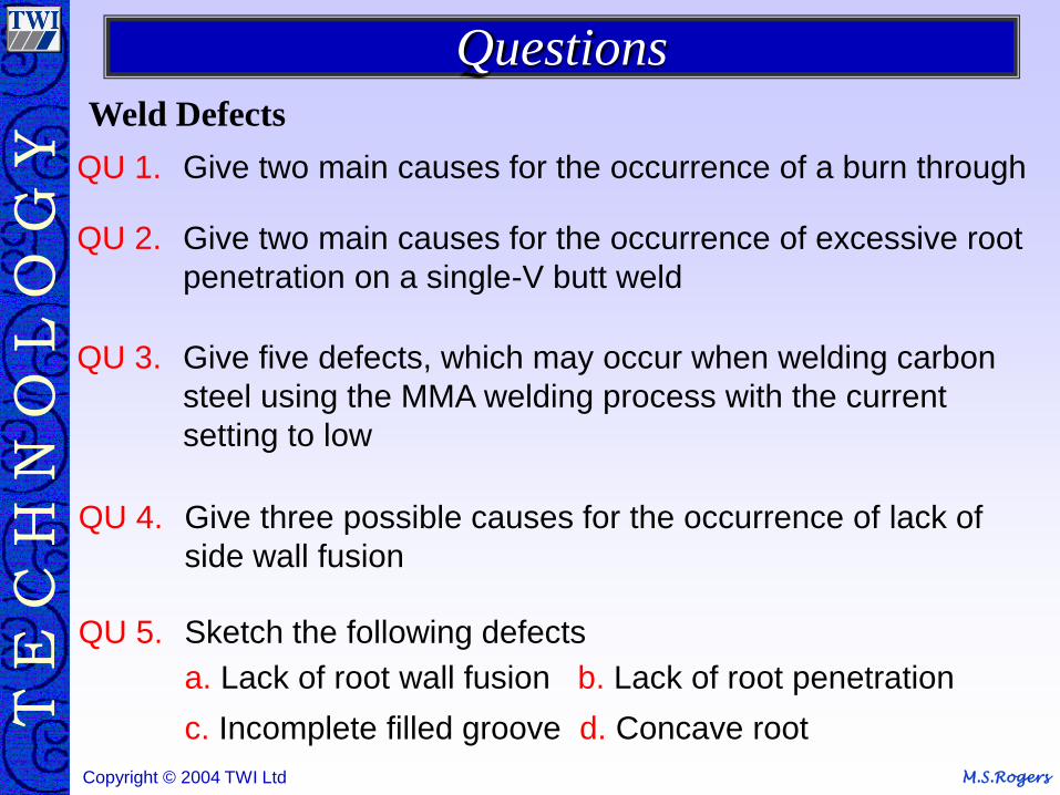
M.S.Rogers Copyright © 2004 TWI Ltd
QU 1. Give two main causes for the occurrence of a burn through
QU 2. Give two main causes for the occurrence of excessive root
penetration on a single-V butt weld
QU 3. Give five defects, which may occur when welding carbon
steel using the MMA welding process with the current
setting to low
QU 4. Give three possible causes for the occurrence of lack of
side wall fusion
QU 5. Sketch the following defects
a. Lack of root wall fusion b. Lack of root penetration
c. Incomplete filled groove d. Concave root
Questions
Weld Defects
M.S.Rogers Copyright © 2004 TWI Ltd
Material Inspection
Course notes section references 6
M.S.Rogers Copyright © 2004 TWI Ltd
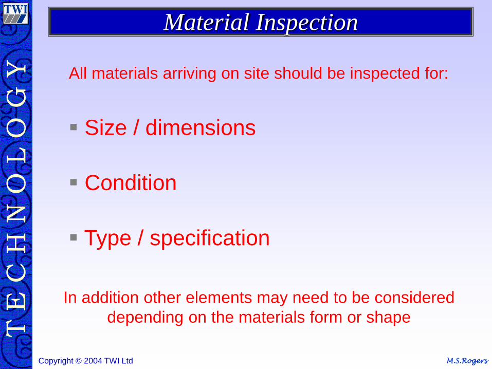
All materials arriving on site should be inspected for:
Size / dimensions
Condition
Type / specification
In addition other elements may need to be considered
depending on the materials form or shape
Material Inspection
M.S.Rogers Copyright © 2004 TWI Ltd
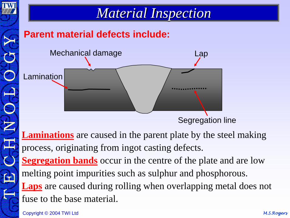
Parent material defects include:
Lamination
Mechanical damage Lap
Segregation line
Laminations are caused in the parent plate by the steel making
process, originating from ingot casting defects.
Segregation bands occur in the centre of the plate and are low
melting point impurities such as sulphur and phosphorous.
Laps are caused during rolling when overlapping metal does not
fuse to the base material.
Material Inspection
M.S.Rogers Copyright © 2004 TWI Ltd
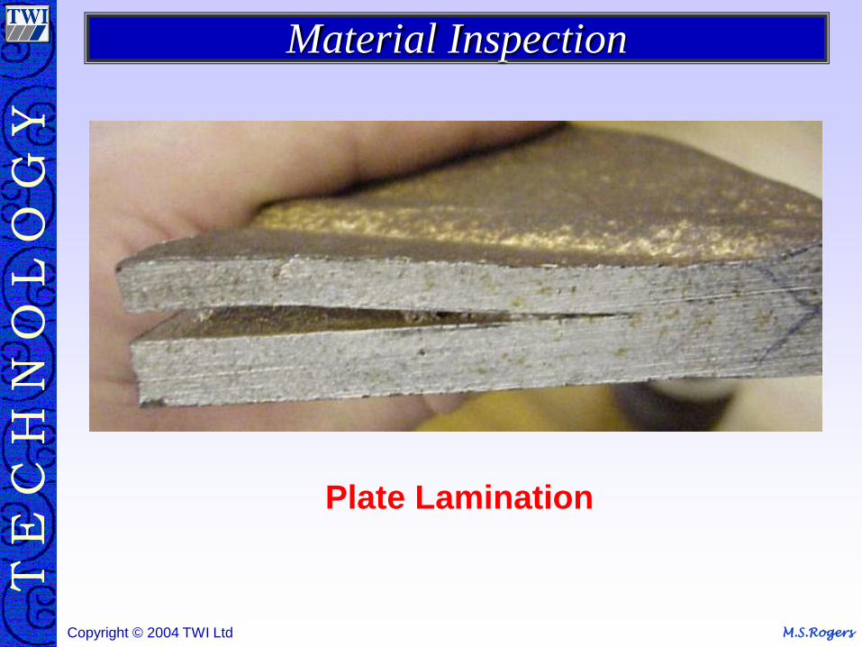
Material Inspection
Plate Lamination
M.S.Rogers Copyright © 2004 TWI Ltd M.S.Rogers Copyright © 2004 TWI Ltd
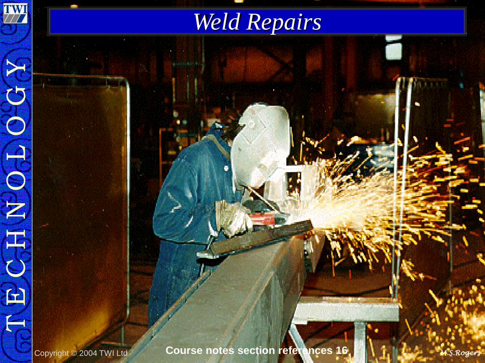
Weld Repairs
Course notes section references 16
M.S.Rogers Copyright © 2004 TWI Ltd
Authorization for repair
Removal and preparation for repair
Testing of repair - visual and NDT
In the event of repair
Weld Repairs
M.S.Rogers Copyright © 2004 TWI Ltd
A weld repair may be used to improve weld profiles or
extensive metal removal
Repairs to fabrication defects are generally easier than
repairs to service failures because the repair procedure
may be followed
The main problem with repairing a weld is the
maintenance of mechanical properties
During the inspection of the removed area prior to welding
the inspector must ensure that the defects have been
totally removed and the original joint profile has been
maintained as close as possible
Weld Repairs
M.S.Rogers Copyright © 2004 TWI Ltd
The specification or procedure will govern how the defective areas are to be removed. The method of removal may be
Grinding
Chipping
Machining
Filing
Oxy-Gas gouging
Arc air gouging
Weld Repairs

M.S.Rogers Copyright © 2004 TWI Ltd
Any Questions