1206e-e66ta sgbu8603-01en
TRANSCRIPT
SEBU8603-01May 2011
Operation andMaintenanceManual1206E-E66TA Industrial EngineBK (Engine)
Important Safety InformationMost accidents that involve product operation, maintenance and repair are caused by failure toobserve basic safety rules or precautions. An accident can often be avoided by recognizing potentiallyhazardous situations before an accident occurs. A person must be alert to potential hazards. Thisperson should also have the necessary training, skills and tools to perform these functions properly.
Improper operation, lubrication, maintenance or repair of this product can be dangerous andcould result in injury or death.
Do not operate or perform any lubrication, maintenance or repair on this product, until you haveread and understood the operation, lubrication, maintenance and repair information.
Safety precautions and warnings are provided in this manual and on the product. If these hazardwarnings are not heeded, bodily injury or death could occur to you or to other persons.
The hazards are identified by the “Safety Alert Symbol” and followed by a “Signal Word” such as“DANGER”, “WARNING” or “CAUTION”. The Safety Alert “WARNING” label is shown below.
The meaning of this safety alert symbol is as follows:
Attention! Become Alert! Your Safety is Involved.
The message that appears under the warning explains the hazard and can be either written orpictorially presented.
Operations that may cause product damage are identified by “NOTICE” labels on the product and inthis publication.
Perkins cannot anticipate every possible circumstance that might involve a potential hazard. Thewarnings in this publication and on the product are, therefore, not all inclusive. If a tool, procedure,work method or operating technique that is not specifically recommended by Perkins is used,you must satisfy yourself that it is safe for you and for others. You should also ensure that theproduct will not be damaged or be made unsafe by the operation, lubrication, maintenance orrepair procedures that you choose.
The information, specifications, and illustrations in this publication are on the basis of information thatwas available at the time that the publication was written. The specifications, torques, pressures,measurements, adjustments, illustrations, and other items can change at any time. These changes canaffect the service that is given to the product. Obtain the complete and most current information beforeyou start any job. Perkins dealers or Perkins distributors have the most current information available.
When replacement parts are required for thisproduct Perkins recommends using Perkins replacement parts.Failure to heed this warning can lead to prema-ture failures, product damage, personal injury ordeath.
SEBU8603-01 3Table of Contents
Table of Contents
Foreword ................................................................. 4
Safety Section
Safety Messages .................................................... 5
General Hazard Information ................................... 8
Burn Prevention ..................................................... 11
Fire Prevention and Explosion Prevention ............ 12
Crushing Prevention and Cutting Prevention ........ 14
Mounting and Dismounting ................................... 14
High Pressure Fuel Lines ..................................... 14
Before Starting Engine .......................................... 16
Engine Starting ..................................................... 16
Engine Stopping ................................................... 16
Electrical System .................................................. 17
Engine Electronics ................................................ 18
Product Information Section
Model Views ......................................................... 20
Product Identification Information ........................ 27
Operation Section
Lifting and Storage ................................................ 29
Gauges and Indicators .......................................... 32
Features and Controls .......................................... 34
Engine Diagnostics ............................................... 45
Engine Starting ..................................................... 51
Engine Operation .................................................. 54
Engine Stopping ................................................... 56
Cold Weather Operation ....................................... 58
Maintenance Section
Refill Capacities .................................................... 62
Maintenance Recommendations .......................... 76
Maintenance Interval Schedule ............................ 78
Warranty Section
Warranty Information ........................................... 110
Reference Information Section
Reference Materials ............................................. 114
Index Section
Index .................................................................... 115
4 SEBU8603-01Foreword
ForewordLiterature InformationThis manual contains safety, operation instructions,lubrication and maintenance information. Thismanual should be stored in or near the engine areain a literature holder or literature storage area. Read,study and keep it with the literature and engineinformation.
English is the primary language for all Perkinspublications. The English used facilitates translationand consistency.
Some photographs or illustrations in this manualshow details or attachments that may be differentfrom your engine. Guards and covers may havebeen removed for illustrative purposes. Continuingimprovement and advancement of product designmay have caused changes to your engine which arenot included in this manual. Whenever a questionarises regarding your engine, or this manual, pleaseconsult with your Perkins dealer or your Perkinsdistributor for the latest available information.
SafetyThis safety section lists basic safety precautions.In addition, this section identifies hazardous,warning situations. Read and understand the basicprecautions listed in the safety section beforeoperating or performing lubrication, maintenance andrepair on this product.
OperationOperating techniques outlined in this manual arebasic. They assist with developing the skills andtechniques required to operate the engine moreefficiently and economically. Skill and techniquesdevelop as the operator gains knowledge of theengine and its capabilities.
The operation section is a reference for operators.Photographs and illustrations guide the operatorthrough procedures of inspecting, starting, operatingand stopping the engine. This section also includes adiscussion of electronic diagnostic information.
MaintenanceThe maintenance section is a guide to engine care.The illustrated, step-by-step instructions are groupedby service hours and/or calendar time maintenanceintervals. Items in the maintenance schedule arereferenced to detailed instructions that follow.
Recommended service should be performed at theappropriate intervals as indicated in the MaintenanceInterval Schedule. The actual operating environmentof the engine also governs the Maintenance IntervalSchedule. Therefore, under extremely severe,dusty, wet or freezing cold operating conditions,more frequent lubrication and maintenance than isspecified in the Maintenance Interval Schedule maybe necessary.
The maintenance schedule items are organized fora preventive maintenance management program. Ifthe preventive maintenance program is followed, aperiodic tune-up is not required. The implementationof a preventive maintenance management programshould minimize operating costs through costavoidances resulting from reductions in unscheduleddowntime and failures.
Maintenance IntervalsPerform maintenance on items at multiples ofthe original requirement. We recommend that themaintenance schedules be reproduced and displayednear the engine as a convenient reminder. We alsorecommend that a maintenance record be maintainedas part of the engine's permanent record.
Your authorized Perkins dealer or your Perkinsdistributor can assist you in adjusting yourmaintenance schedule to meet the needs of youroperating environment.
OverhaulMajor engine overhaul details are not covered inthe Operation and Maintenance Manual exceptfor the interval and the maintenance items in thatinterval. Major repairs should only be carried out byPerkins authorized personnel. Your Perkins dealeror your Perkins distributor offers a variety of optionsregarding overhaul programs. If you experiencea major engine failure, there are also numerousafter failure overhaul options available. Consult withyour Perkins dealer or your Perkins distributor forinformation regarding these options.
California Proposition 65 WarningDiesel engine exhaust and some of its constituentsare known to the State of California to cause cancer,birth defects, and other reproductive harm. Batteryposts, terminals and related accessories contain leadand lead compounds.Wash hands after handling.
SEBU8603-01 5Safety Section
Safety Messages
Safety Sectioni04220089
Safety Messages
There may be several specific warning signs on yourengine. The exact location and a description of thewarning signs are reviewed in this section. Pleasebecome familiar with all warning signs.
Ensure that all of the warning signs are legible. Cleanthe warning signs or replace the warning signs ifthe words cannot be read or if the illustrations arenot visible. Use a cloth, water, and soap to cleanthe warning signs. Do not use solvents, gasoline, orother harsh chemicals. Solvents, gasoline, or harshchemicals could loosen the adhesive that secures thewarning signs. The warning signs that are loosenedcould drop off the engine.
Replace any warning sign that is damaged ormissing. If a warning sign is attached to a part of theengine that is replaced, install a new warning sign onthe replacement part. Your Perkins distributor canprovide new warning signs.
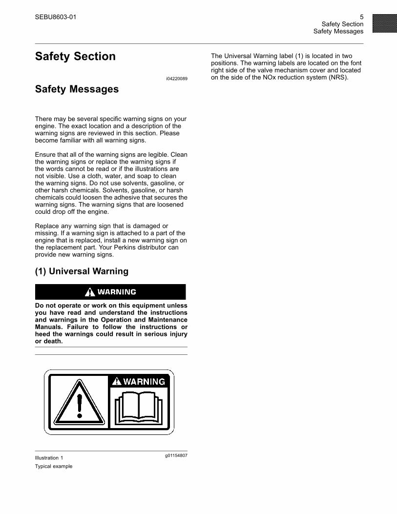
(1) Universal Warning
Do not operate or work on this equipment unlessyou have read and understand the instructionsand warnings in the Operation and MaintenanceManuals. Failure to follow the instructions orheed the warnings could result in serious injuryor death.
g01154807Illustration 1
Typical example
The Universal Warning label (1) is located in twopositions. The warning labels are located on the fontright side of the valve mechanism cover and locatedon the side of the NOx reduction system (NRS).
6 SEBU8603-01Safety SectionSafety Messages
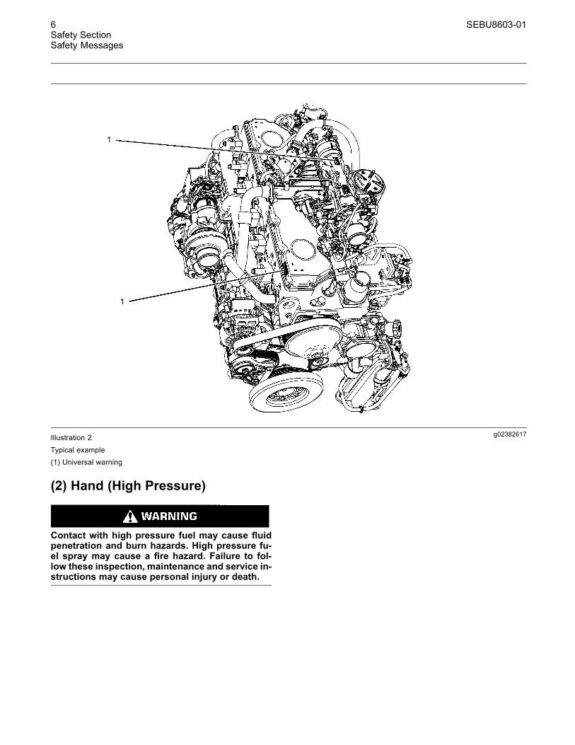
g02382617Illustration 2
Typical example(1) Universal warning
(2) Hand (High Pressure)
Contact with high pressure fuel may cause fluidpenetration and burn hazards. High pressure fu-el spray may cause a fire hazard. Failure to fol-low these inspection, maintenance and service in-structions may cause personal injury or death.
SEBU8603-01 7Safety Section
Safety Messages
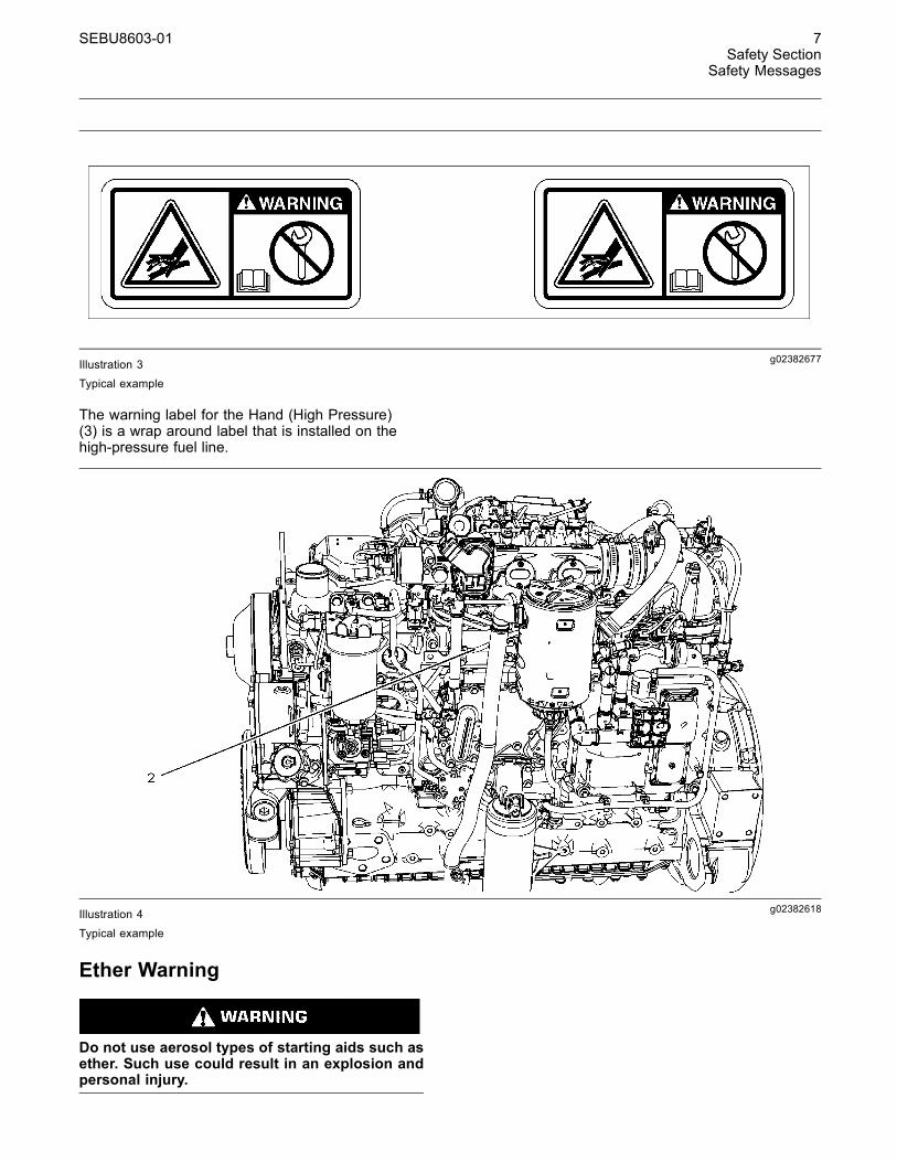
g02382677Illustration 3Typical example
The warning label for the Hand (High Pressure)(3) is a wrap around label that is installed on thehigh-pressure fuel line.
g02382618Illustration 4
Typical example
Ether Warning
Do not use aerosol types of starting aids such asether. Such use could result in an explosion andpersonal injury.
8 SEBU8603-01Safety SectionGeneral Hazard Information
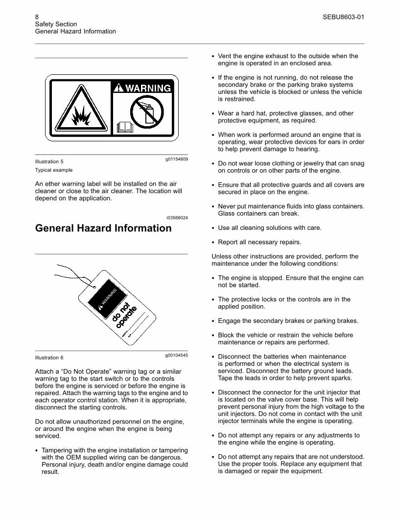
g01154809Illustration 5Typical example
An ether warning label will be installed on the aircleaner or close to the air cleaner. The location willdepend on the application.
i03566024
General Hazard Information
g00104545Illustration 6
Attach a “Do Not Operate” warning tag or a similarwarning tag to the start switch or to the controlsbefore the engine is serviced or before the engine isrepaired. Attach the warning tags to the engine and toeach operator control station. When it is appropriate,disconnect the starting controls.
Do not allow unauthorized personnel on the engine,or around the engine when the engine is beingserviced.
• Tampering with the engine installation or tamperingwith the OEM supplied wiring can be dangerous.Personal injury, death and/or engine damage couldresult.
• Vent the engine exhaust to the outside when theengine is operated in an enclosed area.
• If the engine is not running, do not release thesecondary brake or the parking brake systemsunless the vehicle is blocked or unless the vehicleis restrained.
• Wear a hard hat, protective glasses, and otherprotective equipment, as required.
• When work is performed around an engine that isoperating, wear protective devices for ears in orderto help prevent damage to hearing.
• Do not wear loose clothing or jewelry that can snagon controls or on other parts of the engine.
• Ensure that all protective guards and all covers aresecured in place on the engine.
• Never put maintenance fluids into glass containers.Glass containers can break.
• Use all cleaning solutions with care.
• Report all necessary repairs.
Unless other instructions are provided, perform themaintenance under the following conditions:
• The engine is stopped. Ensure that the engine cannot be started.
• The protective locks or the controls are in theapplied position.
• Engage the secondary brakes or parking brakes.
• Block the vehicle or restrain the vehicle beforemaintenance or repairs are performed.
• Disconnect the batteries when maintenanceis performed or when the electrical system isserviced. Disconnect the battery ground leads.Tape the leads in order to help prevent sparks.
• Disconnect the connector for the unit injector thatis located on the valve cover base. This will helpprevent personal injury from the high voltage to theunit injectors. Do not come in contact with the unitinjector terminals while the engine is operating.
• Do not attempt any repairs or any adjustments tothe engine while the engine is operating.
• Do not attempt any repairs that are not understood.Use the proper tools. Replace any equipment thatis damaged or repair the equipment.
SEBU8603-01 9Safety Section
General Hazard Information
• For initial start-up of a new engine or for starting anengine that has been serviced, make provisions tostop the engine if an overspeed occurs. This maybe accomplished by shutting off the fuel supplyand/or the air supply to the engine.
• Start the engine from the operator's station (cab).Never short across the starting motor terminals orthe batteries. This could bypass the engine neutralstart system and/or the electrical system could bedamaged.
Engine exhaust contains products of combustionwhich may be harmful to your health. Always start theengine and operate the engine in a well ventilatedarea. If the engine is in an enclosed area, vent theengine exhaust to the outside.
Cautiously remove the following parts. To helpprevent spraying or splashing of pressurized fluids,hold a rag over the part that is being removed.
• Filler caps
• Grease fittings
• Pressure taps
• Breathers
• Drain plugs
Use caution when cover plates are removed.Gradually loosen, but do not remove the last twobolts or nuts that are located at opposite ends ofthe cover plate or the device. Before removing thelast two bolts or nuts, pry the cover loose in order torelieve any spring pressure or other pressure.
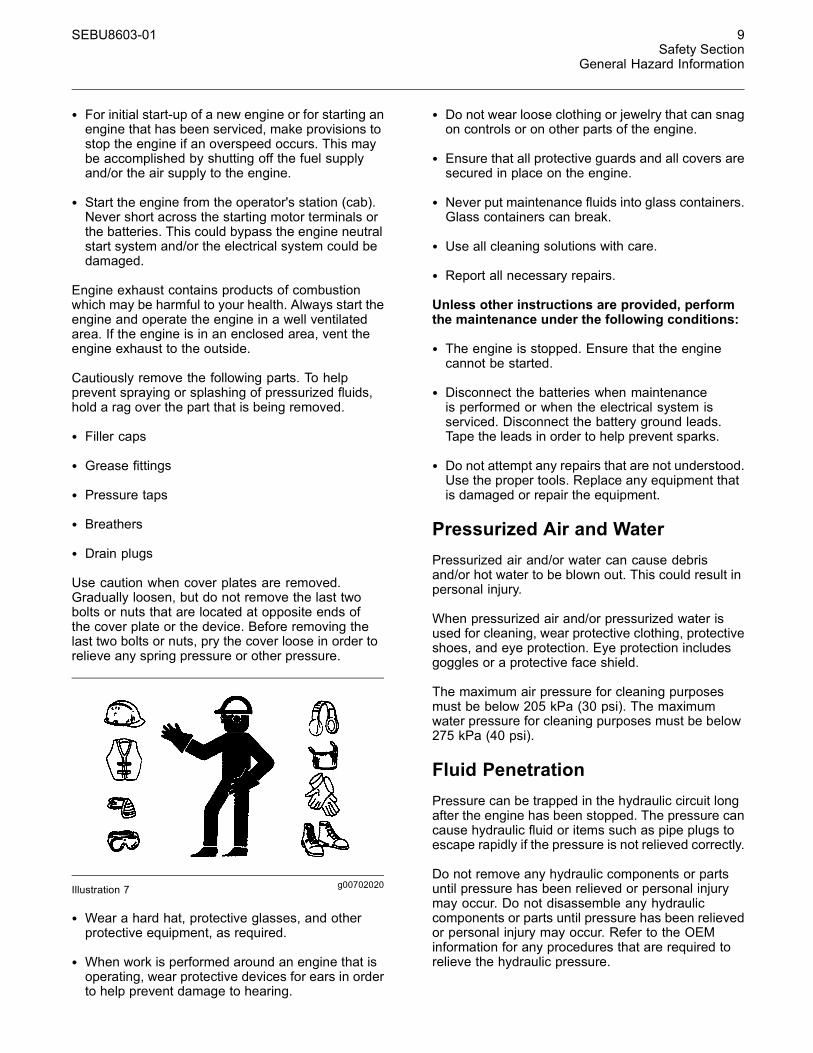
g00702020Illustration 7
• Wear a hard hat, protective glasses, and otherprotective equipment, as required.
• When work is performed around an engine that isoperating, wear protective devices for ears in orderto help prevent damage to hearing.
• Do not wear loose clothing or jewelry that can snagon controls or on other parts of the engine.
• Ensure that all protective guards and all covers aresecured in place on the engine.
• Never put maintenance fluids into glass containers.Glass containers can break.
• Use all cleaning solutions with care.
• Report all necessary repairs.
Unless other instructions are provided, performthe maintenance under the following conditions:
• The engine is stopped. Ensure that the enginecannot be started.
• Disconnect the batteries when maintenanceis performed or when the electrical system isserviced. Disconnect the battery ground leads.Tape the leads in order to help prevent sparks.
• Do not attempt any repairs that are not understood.Use the proper tools. Replace any equipment thatis damaged or repair the equipment.
Pressurized Air and WaterPressurized air and/or water can cause debrisand/or hot water to be blown out. This could result inpersonal injury.
When pressurized air and/or pressurized water isused for cleaning, wear protective clothing, protectiveshoes, and eye protection. Eye protection includesgoggles or a protective face shield.
The maximum air pressure for cleaning purposesmust be below 205 kPa (30 psi). The maximumwater pressure for cleaning purposes must be below275 kPa (40 psi).
Fluid PenetrationPressure can be trapped in the hydraulic circuit longafter the engine has been stopped. The pressure cancause hydraulic fluid or items such as pipe plugs toescape rapidly if the pressure is not relieved correctly.
Do not remove any hydraulic components or partsuntil pressure has been relieved or personal injurymay occur. Do not disassemble any hydrauliccomponents or parts until pressure has been relievedor personal injury may occur. Refer to the OEMinformation for any procedures that are required torelieve the hydraulic pressure.
10 SEBU8603-01Safety SectionGeneral Hazard Information
g00687600Illustration 8
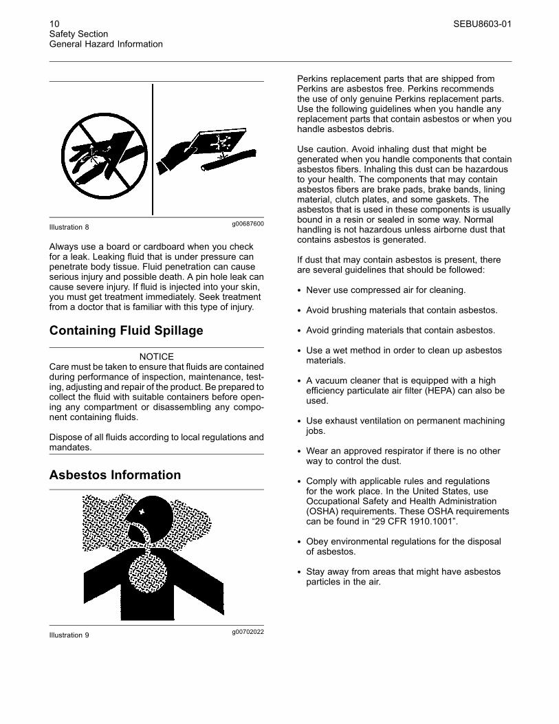
Always use a board or cardboard when you checkfor a leak. Leaking fluid that is under pressure canpenetrate body tissue. Fluid penetration can causeserious injury and possible death. A pin hole leak cancause severe injury. If fluid is injected into your skin,you must get treatment immediately. Seek treatmentfrom a doctor that is familiar with this type of injury.
Containing Fluid Spillage
NOTICECare must be taken to ensure that fluids are containedduring performance of inspection, maintenance, test-ing, adjusting and repair of the product. Be prepared tocollect the fluid with suitable containers before open-ing any compartment or disassembling any compo-nent containing fluids.
Dispose of all fluids according to local regulations andmandates.
Asbestos Information
g00702022Illustration 9
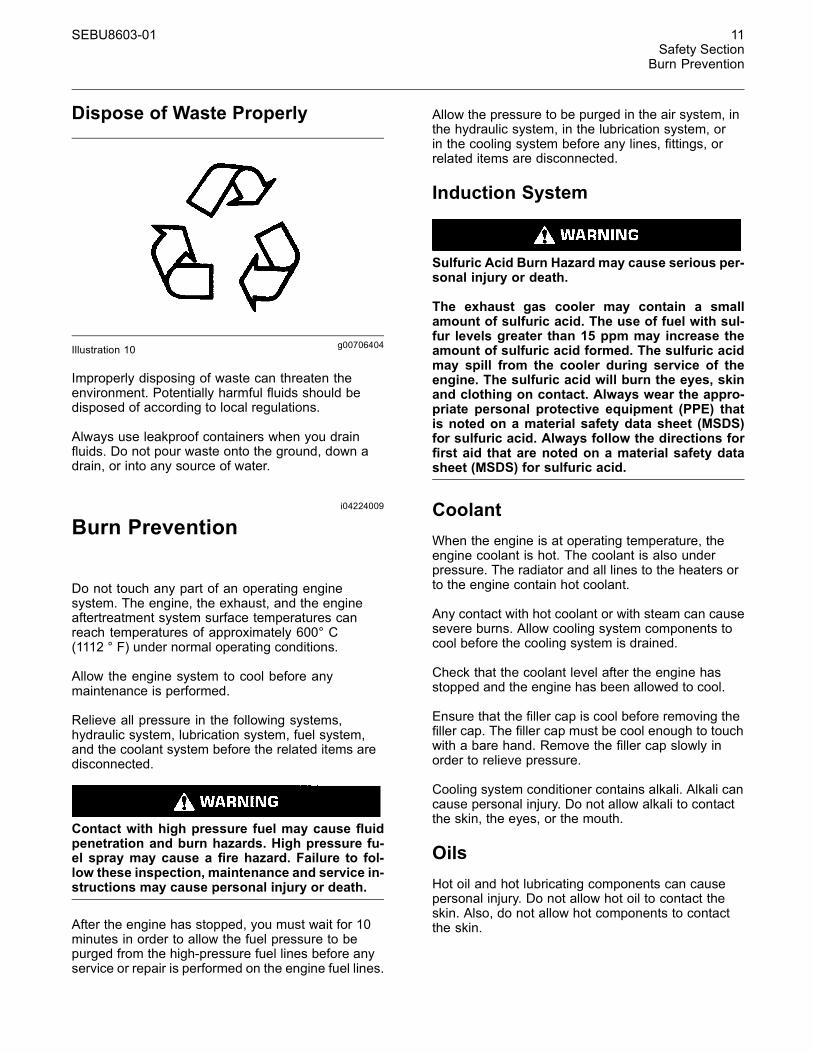
Perkins replacement parts that are shipped fromPerkins are asbestos free. Perkins recommendsthe use of only genuine Perkins replacement parts.Use the following guidelines when you handle anyreplacement parts that contain asbestos or when youhandle asbestos debris.
Use caution. Avoid inhaling dust that might begenerated when you handle components that containasbestos fibers. Inhaling this dust can be hazardousto your health. The components that may containasbestos fibers are brake pads, brake bands, liningmaterial, clutch plates, and some gaskets. Theasbestos that is used in these components is usuallybound in a resin or sealed in some way. Normalhandling is not hazardous unless airborne dust thatcontains asbestos is generated.
If dust that may contain asbestos is present, thereare several guidelines that should be followed:
• Never use compressed air for cleaning.
• Avoid brushing materials that contain asbestos.
• Avoid grinding materials that contain asbestos.
• Use a wet method in order to clean up asbestosmaterials.
• A vacuum cleaner that is equipped with a highefficiency particulate air filter (HEPA) can also beused.
• Use exhaust ventilation on permanent machiningjobs.
• Wear an approved respirator if there is no otherway to control the dust.
• Comply with applicable rules and regulationsfor the work place. In the United States, useOccupational Safety and Health Administration(OSHA) requirements. These OSHA requirementscan be found in “29 CFR 1910.1001”.
• Obey environmental regulations for the disposalof asbestos.
• Stay away from areas that might have asbestosparticles in the air.
SEBU8603-01 11Safety Section
Burn Prevention
Dispose of Waste Properly
g00706404Illustration 10
Improperly disposing of waste can threaten theenvironment. Potentially harmful fluids should bedisposed of according to local regulations.
Always use leakproof containers when you drainfluids. Do not pour waste onto the ground, down adrain, or into any source of water.
i04224009
Burn Prevention
Do not touch any part of an operating enginesystem. The engine, the exhaust, and the engineaftertreatment system surface temperatures canreach temperatures of approximately 600° C(1112 ° F) under normal operating conditions.
Allow the engine system to cool before anymaintenance is performed.
Relieve all pressure in the following systems,hydraulic system, lubrication system, fuel system,and the coolant system before the related items aredisconnected.
Contact with high pressure fuel may cause fluidpenetration and burn hazards. High pressure fu-el spray may cause a fire hazard. Failure to fol-low these inspection, maintenance and service in-structions may cause personal injury or death.
After the engine has stopped, you must wait for 10minutes in order to allow the fuel pressure to bepurged from the high-pressure fuel lines before anyservice or repair is performed on the engine fuel lines.
Allow the pressure to be purged in the air system, inthe hydraulic system, in the lubrication system, orin the cooling system before any lines, fittings, orrelated items are disconnected.
Induction System
Sulfuric Acid Burn Hazard may cause serious per-sonal injury or death.
The exhaust gas cooler may contain a smallamount of sulfuric acid. The use of fuel with sul-fur levels greater than 15 ppm may increase theamount of sulfuric acid formed. The sulfuric acidmay spill from the cooler during service of theengine. The sulfuric acid will burn the eyes, skinand clothing on contact. Always wear the appro-priate personal protective equipment (PPE) thatis noted on a material safety data sheet (MSDS)for sulfuric acid. Always follow the directions forfirst aid that are noted on a material safety datasheet (MSDS) for sulfuric acid.
CoolantWhen the engine is at operating temperature, theengine coolant is hot. The coolant is also underpressure. The radiator and all lines to the heaters orto the engine contain hot coolant.
Any contact with hot coolant or with steam can causesevere burns. Allow cooling system components tocool before the cooling system is drained.
Check that the coolant level after the engine hasstopped and the engine has been allowed to cool.
Ensure that the filler cap is cool before removing thefiller cap. The filler cap must be cool enough to touchwith a bare hand. Remove the filler cap slowly inorder to relieve pressure.
Cooling system conditioner contains alkali. Alkali cancause personal injury. Do not allow alkali to contactthe skin, the eyes, or the mouth.
OilsHot oil and hot lubricating components can causepersonal injury. Do not allow hot oil to contact theskin. Also, do not allow hot components to contactthe skin.
12 SEBU8603-01Safety SectionFire Prevention and Explosion Prevention
BatteriesElectrolyte is an acid. Electrolyte can cause personalinjury. Do not allow electrolyte to contact the skin orthe eyes. Always wear protective glasses for servicingbatteries. Wash hands after touching the batteriesand connectors. Use of gloves is recommended.
i03652933
Fire Prevention and ExplosionPrevention
g00704000Illustration 11
All fuels, most lubricants, and some coolant mixturesare flammable.
Flammable fluids that are leaking or spilled onto hotsurfaces or onto electrical components can causea fire. Fire may cause personal injury and propertydamage.
After the emergency stop button is operated ensurethat you allow 15 minutes, before the engine coversare removed.
Determine whether the engine will be operated in anenvironment that allows combustible gases to bedrawn into the air inlet system. These gases couldcause the engine to overspeed. Personal injury,property damage, or engine damage could result.
If the application involves the presence of combustiblegases, consult your Perkins dealer and/or yourPerkins distributor for additional information aboutsuitable protection devices.
Remove all flammable combustible materials orconductive materials such as fuel, oil, and debris fromthe engine. Do not allow any flammable combustiblematerials or conductive materials to accumulate onthe engine.
Store fuels and lubricants in correctly markedcontainers away from unauthorized persons. Storeoily rags and any flammable materials in protectivecontainers. Do not smoke in areas that are used forstoring flammable materials.
Do not expose the engine to any flame.
Exhaust shields (if equipped) protect hot exhaustcomponents from oil or fuel spray in case of a line,a tube, or a seal failure. Exhaust shields must beinstalled correctly.
Do not weld on lines or tanks that contain flammablefluids. Do not flame cut lines or tanks that containflammable fluid. Clean any such lines or tanksthoroughly with a nonflammable solvent prior towelding or flame cutting.
Wiring must be kept in good condition. All electricalwires must be correctly routed and securely attached.Check all electrical wires daily. Repair any wiresthat are loose or frayed before you operate theengine. Clean all electrical connections and tightenall electrical connections.
Eliminate all wiring that is unattached or unnecessary.Do not use any wires or cables that are smaller thanthe recommended gauge. Do not bypass any fusesand/or circuit breakers.
Arcing or sparking could cause a fire. Secureconnections, recommended wiring, and correctlymaintained battery cables will help to prevent arcingor sparking.
Contact with high pressure fuel may cause fluidpenetration and burn hazards. High pressure fu-el spray may cause a fire hazard. Failure to fol-low these inspection, maintenance and service in-structions may cause personal injury or death.
After the engine has stopped, you must wait for 10minutes in order to allow the fuel pressure to bepurged from the high pressure fuel lines before anyservice or repair is performed on the engine fuel lines.
Ensure that the engine is stopped. Inspect all linesand hoses for wear or for deterioration. The hosesmust be correctly routed. The lines and hoses musthave adequate support and secure clamps.
Oil filters and fuel filters must be correctly installed.The filter housings must be tightened to the correcttorque. Refer to the Disassembly and Assemblymanual for more information.
SEBU8603-01 13Safety Section
Fire Prevention and Explosion Prevention
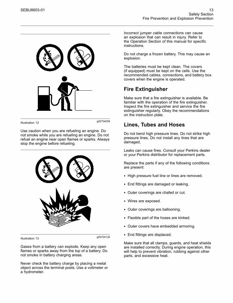
g00704059Illustration 12
Use caution when you are refueling an engine. Donot smoke while you are refueling an engine. Do notrefuel an engine near open flames or sparks. Alwaysstop the engine before refueling.
g00704135Illustration 13
Gases from a battery can explode. Keep any openflames or sparks away from the top of a battery. Donot smoke in battery charging areas.
Never check the battery charge by placing a metalobject across the terminal posts. Use a voltmeter ora hydrometer.
Incorrect jumper cable connections can causean explosion that can result in injury. Refer tothe Operation Section of this manual for specificinstructions.
Do not charge a frozen battery. This may cause anexplosion.
The batteries must be kept clean. The covers(if equipped) must be kept on the cells. Use therecommended cables, connections, and battery boxcovers when the engine is operated.
Fire ExtinguisherMake sure that a fire extinguisher is available. Befamiliar with the operation of the fire extinguisher.Inspect the fire extinguisher and service the fireextinguisher regularly. Obey the recommendationson the instruction plate.
Lines, Tubes and HosesDo not bend high pressure lines. Do not strike highpressure lines. Do not install any lines that aredamaged.
Leaks can cause fires. Consult your Perkins dealeror your Perkins distributor for replacement parts.
Replace the parts if any of the following conditionsare present:
• High pressure fuel line or lines are removed.
• End fittings are damaged or leaking.
• Outer coverings are chafed or cut.
• Wires are exposed.
• Outer coverings are ballooning.
• Flexible part of the hoses are kinked.
• Outer covers have embedded armoring.
• End fittings are displaced.
Make sure that all clamps, guards, and heat shieldsare installed correctly. During engine operation, thiswill help to prevent vibration, rubbing against otherparts, and excessive heat.

14 SEBU8603-01Safety SectionCrushing Prevention and Cutting Prevention
i02143194
Crushing Prevention andCutting Prevention
Support the component correctly when work beneaththe component is performed.
Unless other maintenance instructions are provided,never attempt adjustments while the engine isrunning.
Stay clear of all rotating parts and of all movingparts. Leave the guards in place until maintenanceis performed. After the maintenance is performed,reinstall the guards.
Keep objects away from moving fan blades. The fanblades will throw objects or cut objects.
When objects are struck, wear protective glasses inorder to avoid injury to the eyes.
Chips or other debris may fly off objects when objectsare struck. Before objects are struck, ensure that noone will be injured by flying debris.
i04016709
Mounting and Dismounting
Do not climb on the engine or the engineaftertreatment. The engine and aftertreatment havenot been designed with mounting or dismountinglocations.
Refer to the OEM for the location of foot and handholds for your specific application.
i03550790
High Pressure Fuel Lines
Contact with high pressure fuel may cause fluidpenetration and burn hazards. High pressure fu-el spray may cause a fire hazard. Failure to fol-low these inspection, maintenance and service in-structions may cause personal injury or death.
SEBU8603-01 15Safety Section
High Pressure Fuel Lines
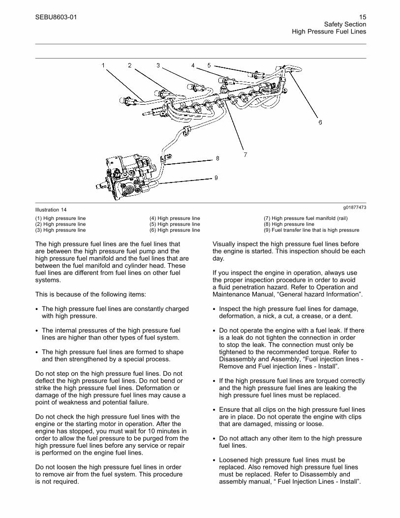
g01877473Illustration 14(1) High pressure line(2) High pressure line(3) High pressure line
(4) High pressure line(5) High pressure line(6) High pressure line
(7) High pressure fuel manifold (rail)(8) High pressure line(9) Fuel transfer line that is high pressure
The high pressure fuel lines are the fuel lines thatare between the high pressure fuel pump and thehigh pressure fuel manifold and the fuel lines that arebetween the fuel manifold and cylinder head. Thesefuel lines are different from fuel lines on other fuelsystems.
This is because of the following items:
• The high pressure fuel lines are constantly chargedwith high pressure.
• The internal pressures of the high pressure fuellines are higher than other types of fuel system.
• The high pressure fuel lines are formed to shapeand then strengthened by a special process.
Do not step on the high pressure fuel lines. Do notdeflect the high pressure fuel lines. Do not bend orstrike the high pressure fuel lines. Deformation ordamage of the high pressure fuel lines may cause apoint of weakness and potential failure.
Do not check the high pressure fuel lines with theengine or the starting motor in operation. After theengine has stopped, you must wait for 10 minutes inorder to allow the fuel pressure to be purged from thehigh pressure fuel lines before any service or repairis performed on the engine fuel lines.
Do not loosen the high pressure fuel lines in orderto remove air from the fuel system. This procedureis not required.
Visually inspect the high pressure fuel lines beforethe engine is started. This inspection should be eachday.
If you inspect the engine in operation, always usethe proper inspection procedure in order to avoida fluid penetration hazard. Refer to Operation andMaintenance Manual, “General hazard Information”.
• Inspect the high pressure fuel lines for damage,deformation, a nick, a cut, a crease, or a dent.
• Do not operate the engine with a fuel leak. If thereis a leak do not tighten the connection in orderto stop the leak. The connection must only betightened to the recommended torque. Refer toDisassembly and Assembly, “Fuel injection lines -Remove and Fuel injection lines - Install”.
• If the high pressure fuel lines are torqued correctlyand the high pressure fuel lines are leaking thehigh pressure fuel lines must be replaced.
• Ensure that all clips on the high pressure fuel linesare in place. Do not operate the engine with clipsthat are damaged, missing or loose.
• Do not attach any other item to the high pressurefuel lines.
• Loosened high pressure fuel lines must bereplaced. Also removed high pressure fuel linesmust be replaced. Refer to Disassembly andassembly manual, “ Fuel Injection Lines - Install”.
16 SEBU8603-01Safety SectionBefore Starting Engine
i02813489
Before Starting Engine
Before the initial start-up of an engine that is new,serviced or repaired, make provision to shut theengine off, in order to stop an overspeed. This maybe accomplished by shutting off the air and/or fuelsupply to the engine.
Overspeed shutdown should occur automatically forengines that are controlled electronically. If automaticshutdown does not occur, press the emergency stopbutton in order to cut the fuel and/or air to the engine.
Inspect the engine for potential hazards.
Before starting the engine, ensure that no one is on,underneath, or close to the engine. Ensure that thearea is free of personnel.
If equipped, ensure that the lighting system for theengine is suitable for the conditions. Ensure that alllights work correctly, if equipped.
All protective guards and all protective covers mustbe installed if the engine must be started in orderto perform service procedures. To help prevent anaccident that is caused by parts in rotation, workaround the parts carefully.
Do not bypass the automatic shutoff circuits. Do notdisable the automatic shutoff circuits. The circuits areprovided in order to help prevent personal injury. Thecircuits are also provided in order to help preventengine damage.
See the Service Manual for repairs and foradjustments.
i03996487
Engine Starting
Do not use aerosol types of starting aids such asether. Such use could result in an explosion andpersonal injury.
If a warning tag is attached to the engine start switch,or to the controls DO NOT start the engine or movethe controls. Consult with the person that attachedthe warning tag before the engine is started.
All protective guards and all protective covers mustbe installed if the engine must be started in orderto perform service procedures. To help prevent anaccident that is caused by parts in rotation, workaround the parts carefully.
Start the engine from the operators compartment orfrom the engine start switch.
Always start the engine according to the procedurethat is described in the Operation and MaintenanceManual, “Engine Starting” topic in the OperationSection. Knowing that the correct procedure will helpto prevent major damage to the engine components.Knowing that the procedure will also help to preventpersonal injury.
To ensure that the jacket water heater (if equipped)and/or the lube oil heater (if equipped) is workingcorrectly, check the water temperature gauge. Also,check the oil temperature gauge during the heateroperation.
Engine exhaust contains products of combustionwhich can be harmful to your health. Always start theengine and operate the engine in a well ventilatedarea. If the engine is started in an enclosed area,vent the engine exhaust to the outside.
Note: The engine is equipped with a device for coldstarting. If the engine will be operated in very coldconditions, then an extra cold starting aid may berequired. Normally, the engine will be equipped withthe correct type of starting aid for your region ofoperation.
These engines are equipped with a glow plug startingaid in each individual cylinder that heats the intake airin order to improve starting. Some Perkins enginesmay have a cold starting system that is controlled bythe ECM that allows a controlled flow of ether intothe engine. The ECM will disconnect the glow plugsbefore the ether is introduced. This system wouldbe installed at the factory.
i02234873
Engine Stopping
Stop the engine according to the procedure inthe Operation and Maintenance Manual, “EngineStopping (Operation Section)” in order to avoidoverheating of the engine and accelerated wear ofthe engine components.
SEBU8603-01 17Safety Section
Electrical System
Use the Emergency Stop Button (if equipped) ONLYin an emergency situation. Do not use the EmergencyStop Button for normal engine stopping. After anemergency stop, DO NOT start the engine until theproblem that caused the emergency stop has beencorrected.
Stop the engine if an overspeed condition occursduring the initial start-up of a new engine or an enginethat has been overhauled.
To stop an electronically controlled engine, cut thepower to the engine and/or shutting off the air supplyto the engine.
i04193189
Electrical System
Never disconnect any charging unit circuit or batterycircuit cable from the battery when the charging unitis operating. A spark can cause the combustiblegases that are produced by some batteries to ignite.
To help prevent sparks from igniting combustiblegases that are produced by some batteries, thenegative “−” cable should be connected last fromthe external power source to the primary position forgrounding.
Check the electrical wires daily for wires thatare loose or frayed. Tighten all loose electricalconnections before the engine is started. Repair allfrayed electrical wires before the engine is started.See the Operation and Maintenance Manual forspecific starting instructions.
Grounding Practices
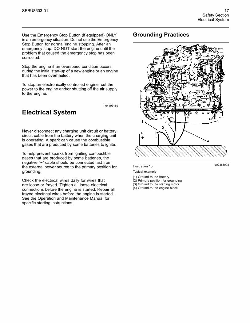
g02383098Illustration 15
Typical example(1) Ground to the battery(2) Primary position for grounding(3) Ground to the starting motor(4) Ground to the engine block
18 SEBU8603-01Safety SectionEngine Electronics
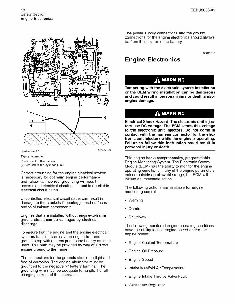
g02383099Illustration 16
Typical example
(5) Ground to the battery(6) Ground to the cylinder block
Correct grounding for the engine electrical systemis necessary for optimum engine performanceand reliability. Incorrect grounding will result inuncontrolled electrical circuit paths and in unreliableelectrical circuit paths.
Uncontrolled electrical circuit paths can result indamage to the crankshaft bearing journal surfacesand to aluminum components.
Engines that are installed without engine-to-frameground straps can be damaged by electricaldischarge.
To ensure that the engine and the engine electricalsystems function correctly, an engine-to-frameground strap with a direct path to the battery must beused. This path may be provided by way of a directengine ground to the frame.
The connections for the grounds should be tight andfree of corrosion. The engine alternator must begrounded to the negative “-” battery terminal. Thegrounding wire must be adequate to handle the fullcharging current of the alternator.
The power supply connections and the groundconnections for the engine electronics should alwaysbe from the isolator to the battery.
i03642610
Engine Electronics
Tampering with the electronic system installationor the OEM wiring installation can be dangerousand could result in personal injury or death and/orengine damage.
Electrical Shock Hazard. The electronic unit injec-tors use DC voltage. The ECM sends this voltageto the electronic unit injectors. Do not come incontact with the harness connector for the elec-tronic unit injectors while the engine is operating.Failure to follow this instruction could result inpersonal injury or death.
This engine has a comprehensive, programmableEngine Monitoring System. The Electronic ControlModule (ECM) has the ability to monitor the engineoperating conditions. If any of the engine parametersextend outside an allowable range, the ECM willinitiate an immediate action.
The following actions are available for enginemonitoring control:
• Warning
• Derate
• Shutdown
The following monitored engine operating conditionshave the ability to limit engine speed and/or theengine power:
• Engine Coolant Temperature
• Engine Oil Pressure
• Engine Speed
• Intake Manifold Air Temperature
• Engine Intake Throttle Valve Fault
• Wastegate Regulator
SEBU8603-01 19Safety Section
Engine Electronics
• Supply Voltage to Sensors
• Fuel Pressure in Manifold (Rail)
• NOx Reduction System
• Engine Aftertreatment System
The Engine Monitoring package can vary for differentengine models and different engine applications.However, the monitoring system and the enginemonitoring control will be similar for all engines.
Note:Many of the engine control systems and displaymodules that are available for Perkins Engines willwork in unison with the Engine Monitoring System.Together, the two controls will provide the enginemonitoring function for the specific engine application.Refer to Troubleshooting for more information on theEngine Monitoring System.
20 SEBU8603-01Product Information SectionModel Views
Product InformationSection
Model Viewsi04171351
Model View Illustrations
The following model views show typical featuresof the engine. Due to individual applications, yourengine may appear different from the illustrations.
Engine views
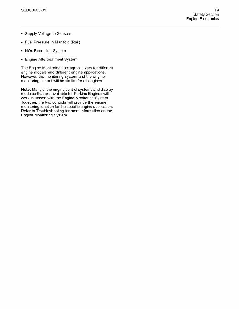
g02361696Illustration 17Typical example
(1) Secondary fuel filter(2) Crankcase breather(3) Electronic control module (ECM)(4) Oil sampling valve
(5) Fuel strainer(6) Oil filter(7) Fuel priming pump(8) Oil gauge (Dipstick)
(9) Primary fuel filter(10) High-pressure fuel pump

SEBU8603-01 21Product Information Section
Model Views
The location of the in-line strainer (5) and the primingpump (7) will depend on the application.
g02361697Illustration 18Typical example
(11) Rear lifting eye(12) NOx reduction system (NRS)(13) Front lifting eye(14) Turbocharger
(15) Back pressure valve(16) Engine oil pan (Sump)(17) Starting motor(18) Engine oil drain plug
(19) Flywheel housing(20) Flywheel(21) Exhaust outlet(22) Exhaust gas cooler
22 SEBU8603-01Product Information SectionModel Views
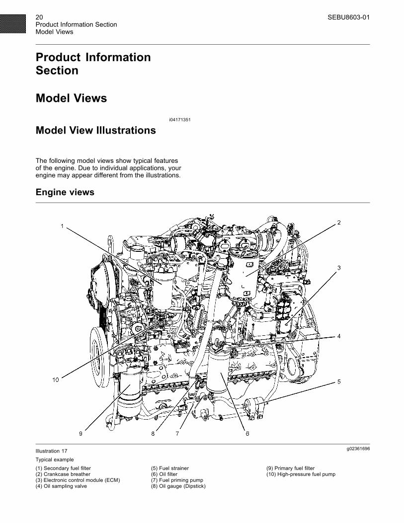
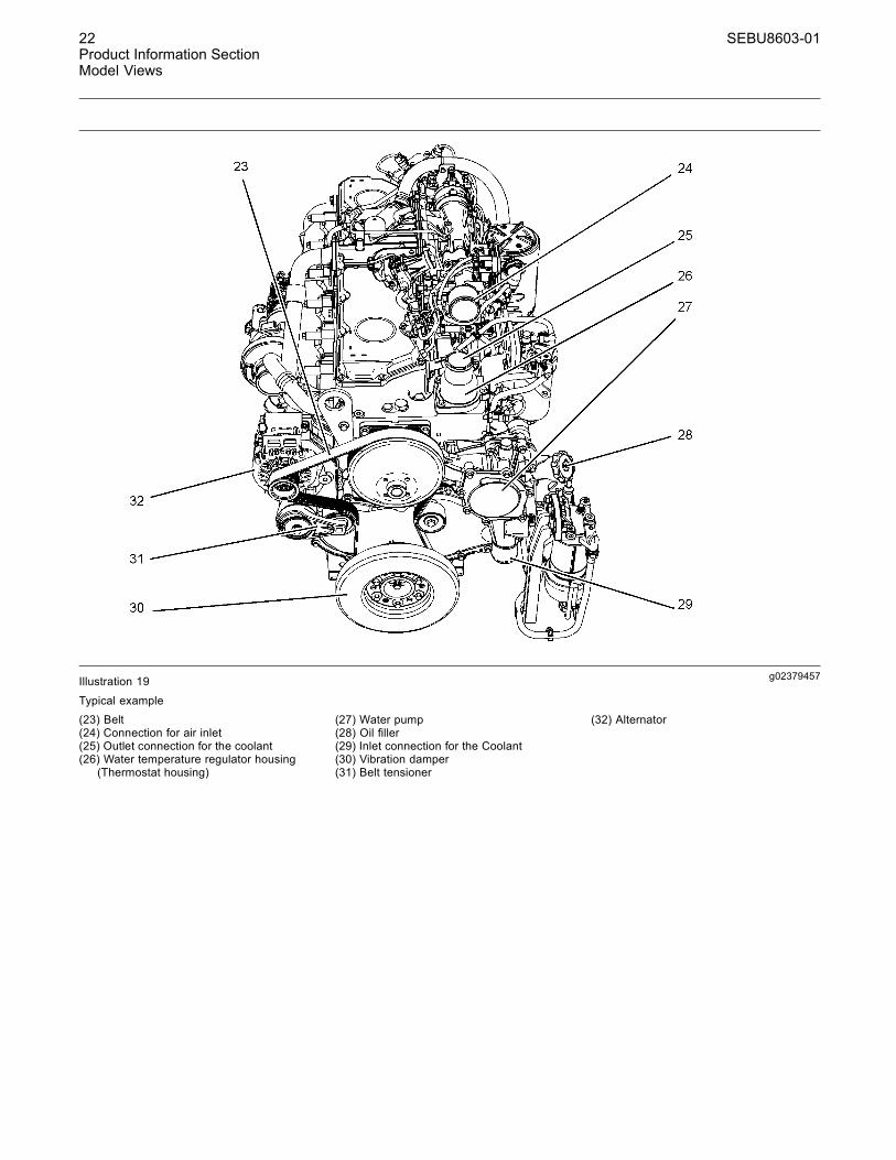
g02379457Illustration 19
Typical example(23) Belt(24) Connection for air inlet(25) Outlet connection for the coolant(26) Water temperature regulator housing
(Thermostat housing)
(27) Water pump(28) Oil filler(29) Inlet connection for the Coolant(30) Vibration damper(31) Belt tensioner
(32) Alternator

SEBU8603-01 23Product Information Section
Model Views
g02381218Illustration 20
Typical example
(33) Coolant drain plug for cylinder block(34) Coolant drain plug for exhaust gas
cooler
24 SEBU8603-01Product Information SectionModel Views
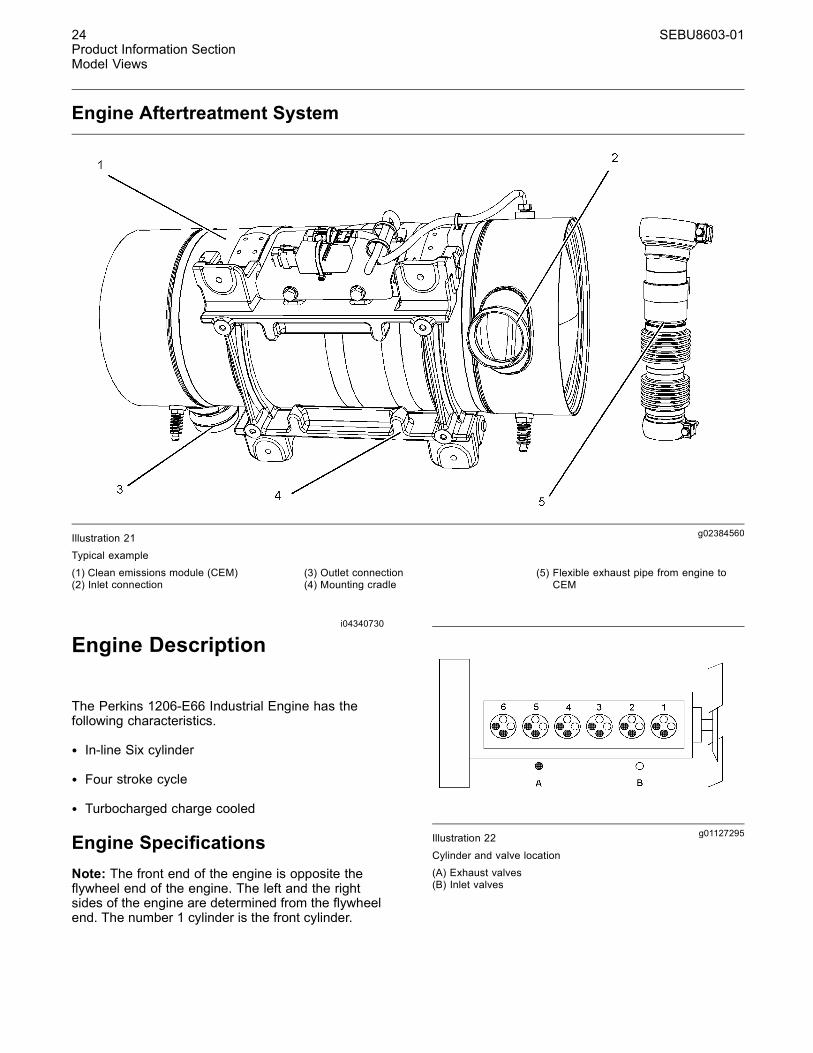
Engine Aftertreatment System
g02384560Illustration 21Typical example
(1) Clean emissions module (CEM)(2) Inlet connection
(3) Outlet connection(4) Mounting cradle
(5) Flexible exhaust pipe from engine toCEM
i04340730
Engine Description
The Perkins 1206-E66 Industrial Engine has thefollowing characteristics.
• In-line Six cylinder
• Four stroke cycle
• Turbocharged charge cooled
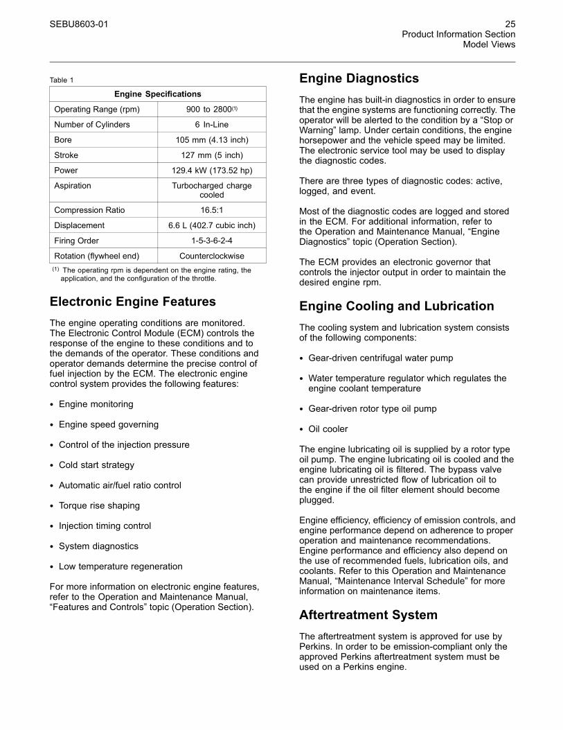
Engine SpecificationsNote: The front end of the engine is opposite theflywheel end of the engine. The left and the rightsides of the engine are determined from the flywheelend. The number 1 cylinder is the front cylinder.
g01127295Illustration 22
Cylinder and valve location(A) Exhaust valves(B) Inlet valves
SEBU8603-01 25Product Information Section
Model Views
Table 1
Engine Specifications
Operating Range (rpm) 900 to 2800(1)
Number of Cylinders 6 In-Line
Bore 105 mm (4.13 inch)
Stroke 127 mm (5 inch)
Power 129.4 kW (173.52 hp)
Aspiration Turbocharged chargecooled
Compression Ratio 16.5:1
Displacement 6.6 L (402.7 cubic inch)
Firing Order 1-5-3-6-2-4
Rotation (flywheel end) Counterclockwise(1) The operating rpm is dependent on the engine rating, theapplication, and the configuration of the throttle.
Electronic Engine FeaturesThe engine operating conditions are monitored.The Electronic Control Module (ECM) controls theresponse of the engine to these conditions and tothe demands of the operator. These conditions andoperator demands determine the precise control offuel injection by the ECM. The electronic enginecontrol system provides the following features:
• Engine monitoring
• Engine speed governing
• Control of the injection pressure
• Cold start strategy
• Automatic air/fuel ratio control
• Torque rise shaping
• Injection timing control
• System diagnostics
• Low temperature regeneration
For more information on electronic engine features,refer to the Operation and Maintenance Manual,“Features and Controls” topic (Operation Section).
Engine DiagnosticsThe engine has built-in diagnostics in order to ensurethat the engine systems are functioning correctly. Theoperator will be alerted to the condition by a “Stop orWarning” lamp. Under certain conditions, the enginehorsepower and the vehicle speed may be limited.The electronic service tool may be used to displaythe diagnostic codes.
There are three types of diagnostic codes: active,logged, and event.
Most of the diagnostic codes are logged and storedin the ECM. For additional information, refer tothe Operation and Maintenance Manual, “EngineDiagnostics” topic (Operation Section).
The ECM provides an electronic governor thatcontrols the injector output in order to maintain thedesired engine rpm.
Engine Cooling and LubricationThe cooling system and lubrication system consistsof the following components:
• Gear-driven centrifugal water pump
• Water temperature regulator which regulates theengine coolant temperature
• Gear-driven rotor type oil pump
• Oil cooler
The engine lubricating oil is supplied by a rotor typeoil pump. The engine lubricating oil is cooled and theengine lubricating oil is filtered. The bypass valvecan provide unrestricted flow of lubrication oil tothe engine if the oil filter element should becomeplugged.
Engine efficiency, efficiency of emission controls, andengine performance depend on adherence to properoperation and maintenance recommendations.Engine performance and efficiency also depend onthe use of recommended fuels, lubrication oils, andcoolants. Refer to this Operation and MaintenanceManual, “Maintenance Interval Schedule” for moreinformation on maintenance items.
Aftertreatment SystemThe aftertreatment system is approved for use byPerkins. In order to be emission-compliant only theapproved Perkins aftertreatment system must beused on a Perkins engine.
26 SEBU8603-01Product Information SectionModel Views
Clean Emission Module (CEM)
The CEM comprises of two main components in asingle unit, the Diesel Oxidation Catalyst DOC andthe Diesel Particulate Filter DPF. The function of theCEM is to ensure that the engine exhaust meetsthe required emissions regulation for the country ofoperation.
The engine exhaust is connected by a flexible pipe tothe CEM. The exhaust gases pass through the DOCin order to remove contaminants, carbon monoxide,and hydrocarbons. The exhaust gases then enter theDPF where any particulate matter soot and ash willbe trapped.
The CEM uses a passive regeneration process toensure that normal operation of the engine removesthe soot. The soot is removed at an equal rate ofwhich the soot is captured. The ash remains in theDPF and must be removed at an engine overhaul.
Engine Service LifeEngine efficiency and maximum utilization of engineperformance depend on the adherence to properoperation and maintenance recommendations. Inaddition, use recommended fuels, coolants, andlubricants. Use the Operation and MaintenanceManual as a guide for required engine maintenance.
Expected engine life is generally predicted by theaverage power that is demanded. The average powerthat is demanded is based on fuel consumption ofthe engine over a period of time. Reduced hours ofoperation at full throttle and/or operating at reducedthrottle settings result in a lower average powerdemand. Reduced hours of operation will increasethe length of operating time before an engineoverhaul is required. For more information, refer tothe Operation and Maintenance Manual, “OverhaulConsiderations” topic (Maintenance Section).
Aftermarket Products and PerkinsEnginesPerkins does not warrant the quality or performanceof non-Perkins fluids and filters.
When auxiliary devices, accessories, or consumables(filters, additives, catalysts,) which are made by othermanufacturers are used on Perkins products, thePerkins warranty is not affected simply because ofsuch use.
However, failures that result from the installationor use of other manufacturers devices,accessories, or consumables are NOT Perkinsdefects. Therefore, the defects are NOT coveredunder the Perkins warranty.
SEBU8603-01 27Product Information Section
Product Identification Information
Product IdentificationInformation
i03865704
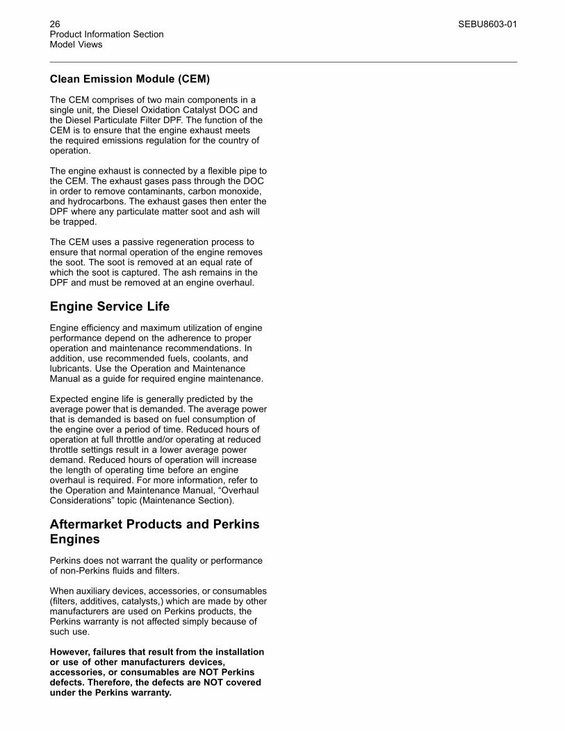
Plate Locations and FilmLocations(Engine Aftertreatment System)
g02109488Illustration 23Typical example
The module arrangement exhaust plate is installedon the mounting plate (1). The location of thearrangement plate mounting plate can alterdepending on the application.
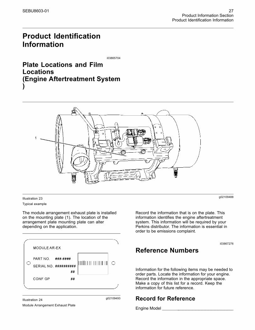
g02109493Illustration 24Module Arrangement Exhaust Plate
Record the information that is on the plate. Thisinformation identifies the engine aftertreatmentsystem. This information will be required by yourPerkins distributor. The information is essential inorder to be emissions complaint.
i03867276
Reference Numbers
Information for the following items may be needed toorder parts. Locate the information for your engine.Record the information in the appropriate space.Make a copy of this list for a record. Keep theinformation for future reference.
Record for ReferenceEngine Model _______________________________________________
28 SEBU8603-01Product Information SectionProduct Identification Information
Engine Serial number _____________________________________
Engine Low Idle rpm ______________________________________
Engine Full Load rpm _____________________________________
Primary Fuel Filter _________________________________________
Water Separator Element ________________________________
Secondary Fuel Filter Element __________________________
Lubrication Oil Filter Element ___________________________
Auxiliary Oil Filter Element _______________________________
Total Lubrication System Capacity _____________________
Total Cooling System Capacity _________________________
Air Cleaner Element _______________________________________
Drive Belt ____________________________________________________
Engine Aftertreatment System
Part Number ________________________________________________
Serial Number ______________________________________________
i04274850
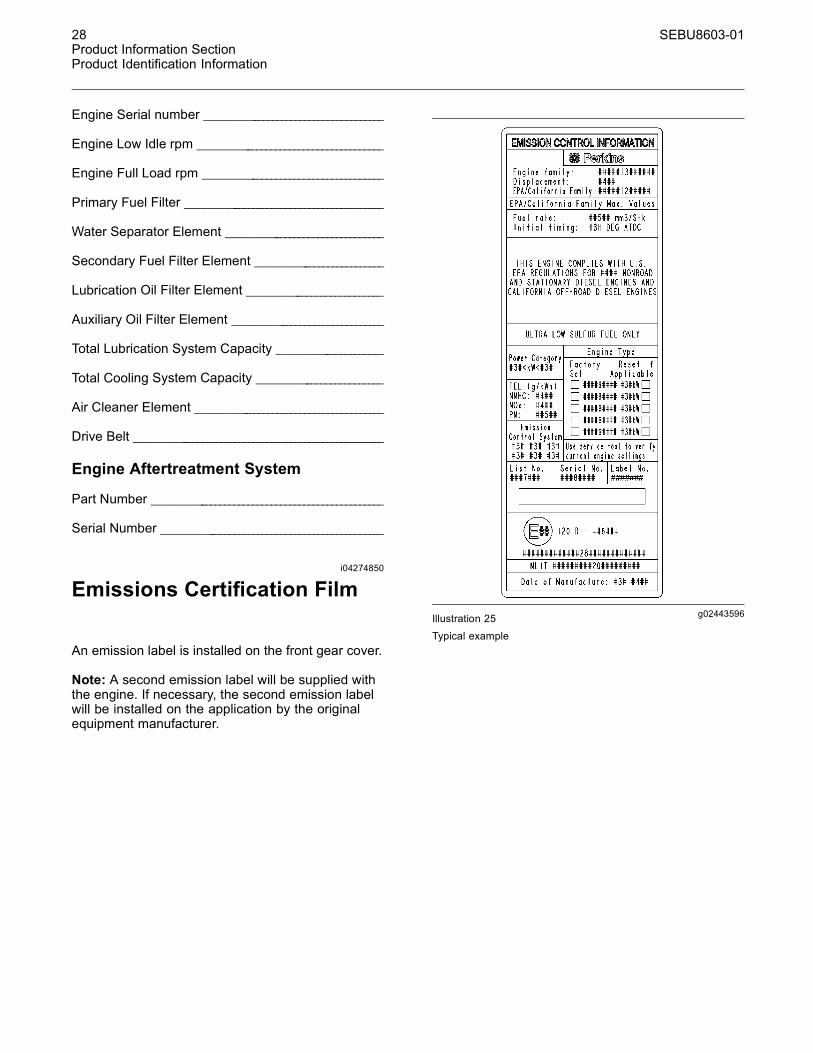
Emissions Certification Film
An emission label is installed on the front gear cover.
Note: A second emission label will be supplied withthe engine. If necessary, the second emission labelwill be installed on the application by the originalequipment manufacturer.
g02443596Illustration 25
Typical example
SEBU8603-01 29Operation SectionLifting and Storage
Operation Section
Lifting and Storagei03977851
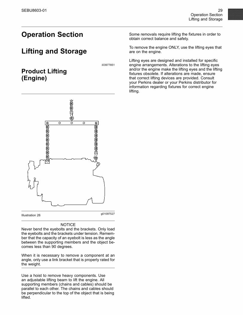
Product Lifting(Engine)
g01097527Illustration 26
NOTICENever bend the eyebolts and the brackets. Only loadthe eyebolts and the brackets under tension. Remem-ber that the capacity of an eyebolt is less as the anglebetween the supporting members and the object be-comes less than 90 degrees.
When it is necessary to remove a component at anangle, only use a link bracket that is properly rated forthe weight.
Use a hoist to remove heavy components. Usean adjustable lifting beam to lift the engine. Allsupporting members (chains and cables) should beparallel to each other. The chains and cables shouldbe perpendicular to the top of the object that is beinglifted.
Some removals require lifting the fixtures in order toobtain correct balance and safety.
To remove the engine ONLY, use the lifting eyes thatare on the engine.
Lifting eyes are designed and installed for specificengine arrangements. Alterations to the lifting eyesand/or the engine make the lifting eyes and the liftingfixtures obsolete. If alterations are made, ensurethat correct lifting devices are provided. Consultyour Perkins dealer or your Perkins distributor forinformation regarding fixtures for correct enginelifting.
30 SEBU8603-01Operation SectionLifting and Storage
i04195469
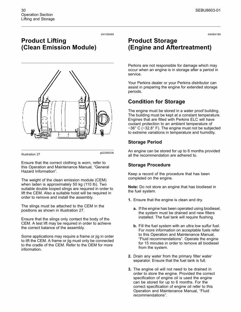
Product Lifting(Clean Emission Module)
g02385036Illustration 27
Ensure that the correct clothing is worn, refer tothis Operation and Maintenance Manual, “GeneralHazard Information”.
The weight of the clean emission module (CEM)when laden is approximately 50 kg (110 lb). Twosuitable double looped slings are required in order tolift the CEM. Also a suitable hoist will be required inorder to remove and install the assembly.
The slings must be attached to the CEM in thepositions as shown in illustration 27.
Ensure that the slings only contact the body of theCEM. A test lift may be required in order to achievethe correct balance of the assembly.
Some applications may require a frame or jig in orderto lift the CEM. A frame or jig must only be connectedto the cradle of the CEM. Refer to the OEM for moreinformation.
i04084189
Product Storage(Engine and Aftertreatment)
Perkins are not responsible for damage which mayoccur when an engine is in storage after a period inservice.
Your Perkins dealer or your Perkins distributor canassist in preparing the engine for extended storageperiods.
Condition for StorageThe engine must be stored in a water proof building.The building must be kept at a constant temperature.Engines that are filled with Perkins ELC will havecoolant protection to an ambient temperature of−36° C (−32.8° F). The engine must not be subjectedto extreme variations in temperature and humidity.
Storage Period
An engine can be stored for up to 6 months providedall the recommendation are adhered to.
Storage Procedure
Keep a record of the procedure that has beencompleted on the engine.
Note: Do not store an engine that has biodiesel inthe fuel system.
1. Ensure that the engine is clean and dry.
a. If the engine has been operated using biodiesel,the system must be drained and new filtersinstalled. The fuel tank will require flushing.
b. Fill the fuel system with an ultra low sulfur fuel.For more information on acceptable fuels referto this Operation and Maintenance Manual,“Fluid recommendations”. Operate the enginefor 15 minutes in order to remove all biodieselfrom the system.
2. Drain any water from the primary filter waterseparator. Ensure that the fuel tank is full.
3. The engine oil will not need to be drained inorder to store the engine. Provided the correctspecification of engine oil is used the enginecan be stored for up to 6 months. For thecorrect specification of engine oil refer to thisOperation and Maintenance Manual, “Fluidrecommendations”.

SEBU8603-01 31Operation SectionLifting and Storage
4. Remove the drive belt from the engine.
Sealed Coolant System
Ensure that the cooling system is filled with PerkinsELC, or an antifreeze that meets “ASTM D6210”specification.
Open Cooling System
Ensure that all cooling drain plugs have beenopened. Allow the coolant to drain. Install the drainplugs. Place a vapor phase inhibitor into the system.The coolant system must be sealed once the vaporphase inhibitor has been introduced. The effect of thevapor phase inhibitor will be lost if the cooling systemis open to the atmosphere.
For maintenance procedures ref to this Operationand Maintenance Manual.
Aftertreatment
No special procedures are required. The exhaustoutlet of the aftertreatment should be capped. Beforestoring, the engine and the aftertreatment must beenclosed in a cover.
Monthly Checks
The crankshaft must be rotated in order to changethe spring loading on the valve train. Rotatethe crankshaft more than 180 degrees. Visiblycheck for damage or corrosion to the engine andaftertreatment.
Ensure that the engine and aftertreatment arecovered completely before storage. Log theprocedure in the record for the engine.
32 SEBU8603-01Operation SectionGauges and Indicators
Gauges and Indicatorsi04220531
Gauges and Indicators0
Your engine may not have the same gauges or all ofthe gauges that are described. For more informationabout the gauge package, see the OEM information.
Gauges provide indications of engine performance.Ensure that the gauges are in good working order.Determine the normal operating range by observingthe gauges over a period of time.
Noticeable changes in gauge readings indicatepotential gauge or engine problems. Problems mayalso be indicated by gauge readings that changeeven if the readings are within specifications.Determine and correct the cause of any significantchange in the readings. Consult your Perkinsdistributor for assistance.
Some engine applications are equipped with IndicatorLamps. Indicator lamps can be used as a diagnosticaid. There are two lamps. One lamp has an orangelens and the other lamp has a red lens.
These indicator lamps can be used in two ways:
• The indicator lamps can be used to identify thecurrent operational status of the engine. Theindicator lamps can also indicate that the enginehas a fault. This system is automatically operatedvia the ignition switch.
• The indicator lamps can be used to identify activediagnostic codes. This system is activated bypressing the Flash Code button.
Refer to the Troubleshooting Guide, “IndicatorLamps” for further information.
NOTICEIf no oil pressure is indicated, STOP the engine. Ifmaximum coolant temperature is exceeded, STOPthe engine. Engine damage can result.
Engine Oil Pressure – The oil pressureshould be greatest after a cold engine isstarted. The typical engine oil pressure with
SAE10W40 is 350 to 450 kPa ( 50 to 65 psi) at ratedrpm.
A lower oil pressure is normal at low idle. If the loadis stable and the gauge reading changes, performthe following procedure:
1. Remove the load.
2. Stop the engine.
3. Check and maintain the oil level.
Jacket Water Coolant Temperature –Typical temperature range is 82° to 94°C(179.6° to 201.2°F). This temperature range
will vary according to engine load and the ambienttemperature.
A 100 kPa (14.5 psi) radiator cap must be installedon the cooling system. The maximum temperaturefor the cooling system is 108° C (226.4° F). Thistemperature is measured at the outlet for thewater temperature regulator. The engine coolanttemperature is regulated by the engine sensorsand the engine ECM. This programming cannot bealtered. An engine derate can occur if the maximumengine coolant temperature is exceeded.
If the engine is operating above the normal range,reduce the engine load. If high coolant temperaturesare a frequent event, perform the followingprocedures:
1. Reduce the load and the engine rpm.
2. Determine if the engine must be shut downimmediately or if the engine can be cooled byreducing the load.
3. Inspect the cooling system for leaks. If necessary,consult your Perkins distributor for assistance.
Tachometer – This gauge indicates enginespeed (rpm). When the throttle control leveris moved to the full throttle position without
load, the engine is running at high idle. The engine isrunning at the full load rpm when the throttle controllever is at the full throttle position with maximumrated load.
NOTICEOperation at speeds exceeding high idle rpm shouldbe kept to a minimum. Overspeeding can result in se-rious damage to the engine.
Ammeter – This gauge indicates theamount of charge or discharge in thebattery charging circuit. Operation of the
indicator should be to the “+” side of “0” (zero).
Fuel Level – This gauge indicates the fuellevel in the fuel tank. The fuel level gaugeoperates when the “START/STOP” switch
is in the “on” position.

SEBU8603-01 33Operation Section
Gauges and Indicators
Service Hour Meter – The gauge indicatestotal operating hours of the engine.
Indicator LampsThere is four indicator lamps that are available.
• Shutdown Lamp
• Warning Lamp
• Wait to Start Lamp
• Low Oil Pressure Lamp
For information, refer to this manual, “MonitoringSystem (Table for the Indicator Lamps)” for thesequence of operation of the shutdown lamp and thewarning lamp.
The function of the wait to start lamp is automaticallycontrolled at engine start-up.
The function of the low oil pressure lamp is controlledby the engine ECM. If low oil pressure is detected,the lamp will be illuminated. The reason for theillumination of the low-pressure lamp should beinvestigated immediately.
All lamps will illuminate for 2 seconds in order tocheck that the lamps are functioning when thekeyswitch is turned to the ON position. If any of thelamps stay illuminated, the reason for illuminationshould be investigated immediately.
Instrument panels and DisplaysIn order to monitor the engine a wide verity ofinstrument panels are available. These instrumentpanels can contain the indicator lamps and thegauges for the application.
Also available are mini power displays andperformance monitors. These displays and monitorscan show the operator the following engineinformation.
• The system configuration parameters
• The customer specified parameters
• Diagnostic codes
• Event codes
• Coolant temperature
• Oil temperature
• Oil pressure
• Intake temperature
• Intake pressure
• Atmospheric pressure
• Fuel temperature
34 SEBU8603-01Operation SectionFeatures and Controls
Features and Controlsi04340829
Monitoring System
If the Shutdown mode has been selected and thewarning indicator activates, engine shutdownmaytake as little as 20 seconds from the time the warn-ing indicator is activated. Depending on the ap-plication, special precautions should be taken toavoid personal injury. The engine can be restartedfollowing shutdown for emergency maneuvers, ifnecessary.
NOTICEThe Engine Monitoring System is not a guaranteeagainst catastrophic failures. Programmed delaysand derate schedules are designed to minimize falsealarms and provide time for the operator to stop theengine.
The following parameters are monitored:
• Coolant temperature
• Intake manifold air temperature
• Intake manifold air pressure
• Oil pressure
• Pressure in the fuel rail
• Engine speed/timing
• Fuel temperature
• Atmospheric pressure (Barometric pressure)
• The Inlet pressure and outlet pressure of the NOxreduction system
• Temperature of the NOx reduction system
• Water in fuel switch
• The amount of soot in the Diesel particulate filter
Programmable Options andSystems Operation
If the Warning/Derate/Shutdown mode has beenselected and the warning indicator activates,bring the engine to a stop whenever possible. De-pending on the application, special precautionsshould be taken to avoid personal injury.
The engine can be programmed to the followingmodes:
“Warning”
The orange “Warning” lamp will turn “ON” and thewarning signal is activated continuously in order toalert the operator that one or more of the engineparameters is not within normal operating range.
“Derate”
The orange warning lamp will be flashing. After thewarning, the engine power will be derated.
The engine will be derated if the engine exceedspreset operational limits. The engine derate isachieved by restricting the amount of fuel that isavailable for each injection. The amount of thisreduction of fuel is dependent on the severity of thefault that has caused the engine derate, typically upto a limit of 50%. This reduction in fuel results in apredetermined reduction in engine power.
“Shutdown”
The orange warning lamp will be flashing and the redshutdown lamp will be on solid. After the warning,the engine power will be derated. The engine willcontinue at the rpm of the set derate until a shutdownof the engine occurs. The engine can be restartedafter a shutdown for use in an emergency.
A shutdown of the engine may occur in as littleas 20 seconds. The engine can be restarted aftera shutdown for use in an emergency. However,the cause of the initial shutdown may still exist.The engine may shut down again in as little as 20seconds.
If there is a signal for high coolant temperature,there will be a 2 second delay in order to verify thecondition.
If there is a signal for low oil pressure, there will be a2 second delay in order to verify the condition.
SEBU8603-01 35Operation Section
Features and Controls
For information on the operation of the warning lampsand the shutdown lamp, refer to this Operation andMaintenance Manual, “ Monitoring System (Tablefor Indicator Lamps)”. For each of the programmedmodes, refer to Troubleshooting Guide, “IndicatorLamps” for more information on Indicator Lamps.
For more information or assistance for repairs,consult your Perkins distributor or your Perkinsdealer.
36 SEBU8603-01Operation SectionFeatures and Controls
i04201172
Monitoring System(Table for the Indicator lamps)
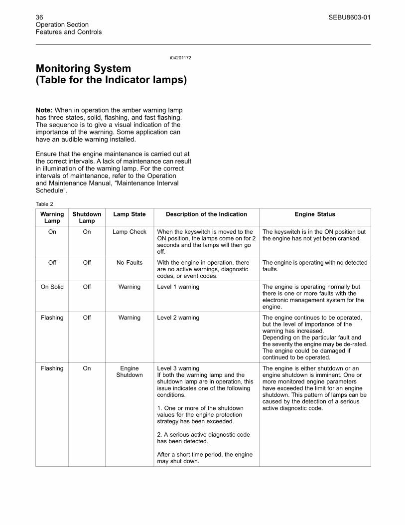
Note: When in operation the amber warning lamphas three states, solid, flashing, and fast flashing.The sequence is to give a visual indication of theimportance of the warning. Some application canhave an audible warning installed.
Ensure that the engine maintenance is carried out atthe correct intervals. A lack of maintenance can resultin illumination of the warning lamp. For the correctintervals of maintenance, refer to the Operationand Maintenance Manual, “Maintenance IntervalSchedule”.
Table 2
WarningLamp
ShutdownLamp
Lamp State Description of the Indication Engine Status
On On Lamp Check When the keyswitch is moved to theON position, the lamps come on for 2seconds and the lamps will then gooff.
The keyswitch is in the ON position butthe engine has not yet been cranked.
Off Off No Faults With the engine in operation, thereare no active warnings, diagnosticcodes, or event codes.
The engine is operating with no detectedfaults.
On Solid Off Warning Level 1 warning The engine is operating normally butthere is one or more faults with theelectronic management system for theengine.
Flashing Off Warning Level 2 warning The engine continues to be operated,but the level of importance of thewarning has increased.Depending on the particular fault andthe severity the engine may be de-rated.The engine could be damaged ifcontinued to be operated.
Flashing On EngineShutdown
Level 3 warningIf both the warning lamp and theshutdown lamp are in operation, thisissue indicates one of the followingconditions.
1. One or more of the shutdownvalues for the engine protectionstrategy has been exceeded.
2. A serious active diagnostic codehas been detected.
After a short time period, the enginemay shut down.
The engine is either shutdown or anengine shutdown is imminent. One ormore monitored engine parametershave exceeded the limit for an engineshutdown. This pattern of lamps can becaused by the detection of a seriousactive diagnostic code.
SEBU8603-01 37Operation Section
Features and Controls
i04215952
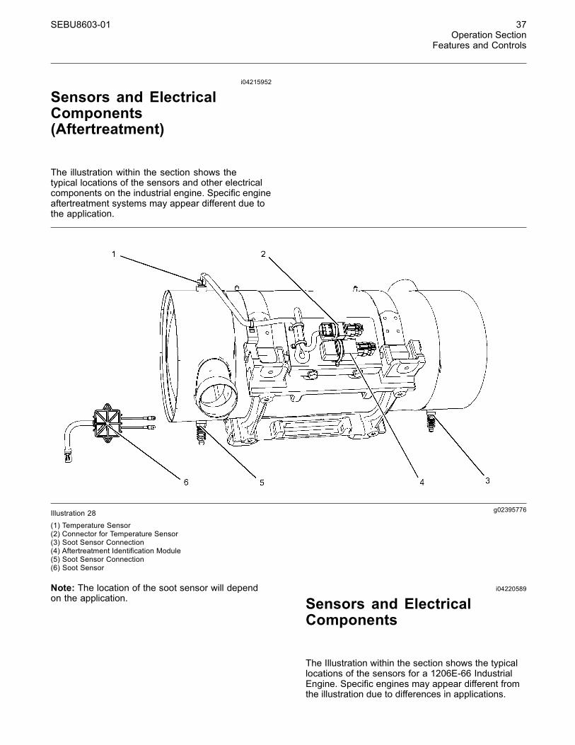
Sensors and ElectricalComponents(Aftertreatment)
The illustration within the section shows thetypical locations of the sensors and other electricalcomponents on the industrial engine. Specific engineaftertreatment systems may appear different due tothe application.
g02395776Illustration 28(1) Temperature Sensor(2) Connector for Temperature Sensor(3) Soot Sensor Connection(4) Aftertreatment Identification Module(5) Soot Sensor Connection(6) Soot Sensor
Note: The location of the soot sensor will dependon the application.
i04220589
Sensors and ElectricalComponents
The Illustration within the section shows the typicallocations of the sensors for a 1206E-66 IndustrialEngine. Specific engines may appear different fromthe illustration due to differences in applications.

38 SEBU8603-01Operation SectionFeatures and Controls
g02392837Illustration 29
Typical example(1) Coolant Temperature Sensor(2) Wastegate Regulator(3) Throttle valve(4) Fuel Pressure Sensor (Fuel Rail
Pressure Sensor)(5) Intake Manifold Air Temperature Sensor
(6) Intake Manifold Pressure Sensor(7) Diagnostic Connector(8) Electronic Control Module (ECM)(9) Atmospheric Pressure Sensor
(Barometric Pressure Sensor)(10) Primary Speed/Timing Sensor
(11) Oil Pressure Sensor(12) Fuel Priming Pump(13) Water in Fuel Switch(14) Fuel Temperature Sensor(15) Solenoid for the High Pressure Fuel
Pump
Note: The location of the secondary fuel filter, theprimary fuel filter, and the fuel priming pump willdepend on the application. These locations will affectitems (12, and 13).
SEBU8603-01 39Operation Section
Features and Controls
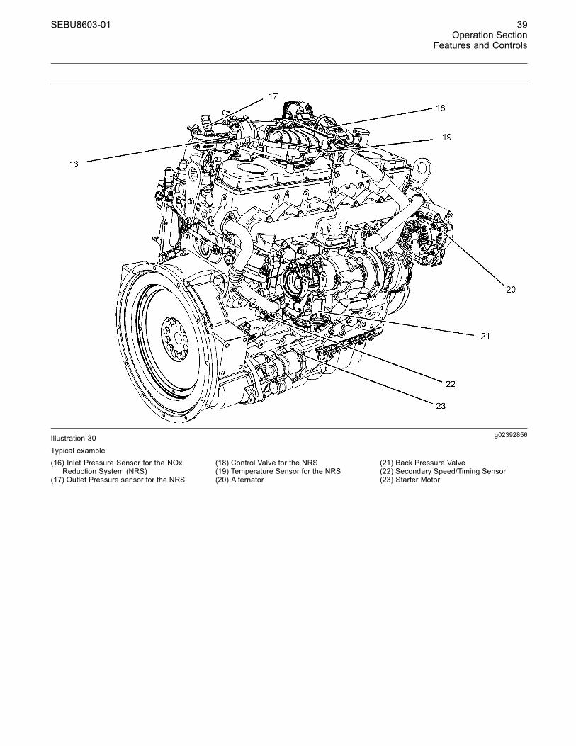
g02392856Illustration 30
Typical example(16) Inlet Pressure Sensor for the NOx
Reduction System (NRS)(17) Outlet Pressure sensor for the NRS
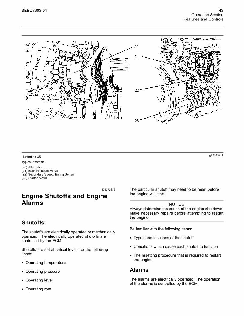
(18) Control Valve for the NRS(19) Temperature Sensor for the NRS(20) Alternator
(21) Back Pressure Valve(22) Secondary Speed/Timing Sensor(23) Starter Motor
40 SEBU8603-01Operation SectionFeatures and Controls
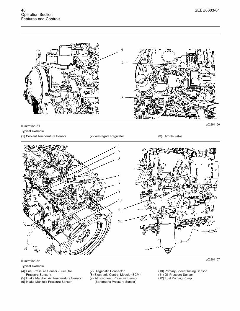
g02394156Illustration 31Typical example
(1) Coolant Temperature Sensor (2) Wastegate Regulator (3) Throttle valve
g02394157Illustration 32Typical example
(4) Fuel Pressure Sensor (Fuel RailPressure Sensor)
(5) Intake Manifold Air Temperature Sensor(6) Intake Manifold Pressure Sensor
(7) Diagnostic Connector(8) Electronic Control Module (ECM)(9) Atmospheric Pressure Sensor
(Barometric Pressure Sensor)
(10) Primary Speed/Timing Sensor(11) Oil Pressure Sensor(12) Fuel Priming Pump
SEBU8603-01 41Operation Section
Features and Controls
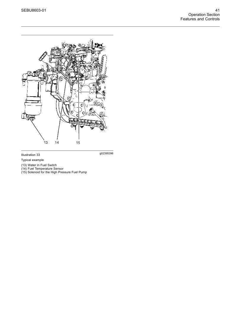
g02395396Illustration 33
Typical example
(13) Water in Fuel Switch(14) Fuel Temperature Sensor(15) Solenoid for the High Pressure Fuel Pump
42 SEBU8603-01Operation SectionFeatures and Controls
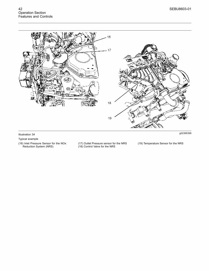
g02395399Illustration 34
Typical example
(16) Inlet Pressure Sensor for the NOxReduction System (NRS)
(17) Outlet Pressure sensor for the NRS(18) Control Valve for the NRS
(19) Temperature Sensor for the NRS
SEBU8603-01 43Operation Section
Features and Controls
g02395417Illustration 35
Typical example
(20) Alternator(21) Back Pressure Valve(22) Secondary Speed/Timing Sensor(23) Starter Motor
i04372685
Engine Shutoffs and EngineAlarms
ShutoffsThe shutoffs are electrically operated or mechanicallyoperated. The electrically operated shutoffs arecontrolled by the ECM.
Shutoffs are set at critical levels for the followingitems:
• Operating temperature
• Operating pressure
• Operating level
• Operating rpm
The particular shutoff may need to be reset beforethe engine will start.
NOTICEAlways determine the cause of the engine shutdown.Make necessary repairs before attempting to restartthe engine.
Be familiar with the following items:
• Types and locations of the shutoff
• Conditions which cause each shutoff to function
• The resetting procedure that is required to restartthe engine
AlarmsThe alarms are electrically operated. The operationof the alarms is controlled by the ECM.
44 SEBU8603-01Operation SectionFeatures and Controls
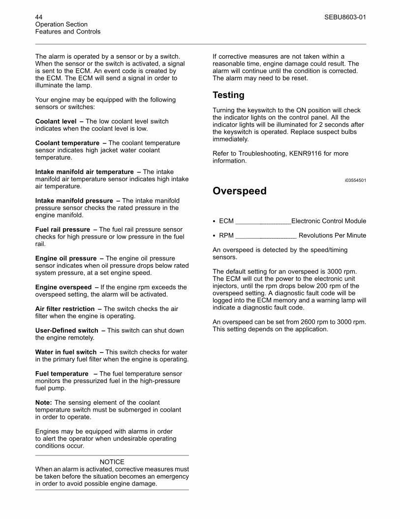
The alarm is operated by a sensor or by a switch.When the sensor or the switch is activated, a signalis sent to the ECM. An event code is created bythe ECM. The ECM will send a signal in order toilluminate the lamp.
Your engine may be equipped with the followingsensors or switches:
Coolant level – The low coolant level switchindicates when the coolant level is low.
Coolant temperature – The coolant temperaturesensor indicates high jacket water coolanttemperature.
Intake manifold air temperature – The intakemanifold air temperature sensor indicates high intakeair temperature.
Intake manifold pressure – The intake manifoldpressure sensor checks the rated pressure in theengine manifold.
Fuel rail pressure – The fuel rail pressure sensorchecks for high pressure or low pressure in the fuelrail.
Engine oil pressure – The engine oil pressuresensor indicates when oil pressure drops below ratedsystem pressure, at a set engine speed.
Engine overspeed – If the engine rpm exceeds theoverspeed setting, the alarm will be activated.
Air filter restriction – The switch checks the airfilter when the engine is operating.
User-Defined switch – This switch can shut downthe engine remotely.
Water in fuel switch – This switch checks for waterin the primary fuel filter when the engine is operating.
Fuel temperature – The fuel temperature sensormonitors the pressurized fuel in the high-pressurefuel pump.
Note: The sensing element of the coolanttemperature switch must be submerged in coolantin order to operate.
Engines may be equipped with alarms in orderto alert the operator when undesirable operatingconditions occur.
NOTICEWhen an alarm is activated, corrective measuresmustbe taken before the situation becomes an emergencyin order to avoid possible engine damage.
If corrective measures are not taken within areasonable time, engine damage could result. Thealarm will continue until the condition is corrected.The alarm may need to be reset.
TestingTurning the keyswitch to the ON position will checkthe indicator lights on the control panel. All theindicator lights will be illuminated for 2 seconds afterthe keyswitch is operated. Replace suspect bulbsimmediately.
Refer to Troubleshooting, KENR9116 for moreinformation.
i03554501
Overspeed
• ECM ______________________Electronic Control Module
• RPM ________________________ Revolutions Per Minute
An overspeed is detected by the speed/timingsensors.
The default setting for an overspeed is 3000 rpm.The ECM will cut the power to the electronic unitinjectors, until the rpm drops below 200 rpm of theoverspeed setting. A diagnostic fault code will belogged into the ECM memory and a warning lamp willindicate a diagnostic fault code.
An overspeed can be set from 2600 rpm to 3000 rpm.This setting depends on the application.
SEBU8603-01 45Operation SectionEngine Diagnostics
Engine Diagnosticsi02651093
Self-Diagnostics
Perkins electronic engines have the capability toperform a self-diagnostics test. When the systemdetects an active problem, a diagnostic lampis activated. Diagnostic codes will be stored inpermanent memory in the Electronic Control Module(ECM). The diagnostic codes can be retrievedby using the electronic service tool. Refer toTroubleshooting , “Electronic Service Tools” forfurther information.
Some installations have electronic displays thatprovide direct readouts of the engine diagnosticcodes. Refer to the manual that is providedby the OEM for more information on retrievingengine diagnostic codes. Alternatively refer toTroubleshooting , “Indicator Lamps” for furtherinformation.
Active codes represent problems that currently exist.These problems should be investigated first.
Logged codes represent the following items:
• Intermittent problems
• Recorded events
• Performance history
The problems may have been repaired since thelogging of the code. These codes do not indicate thata repair is needed. The codes are guides or signalswhen a situation exists. Codes may be helpful totroubleshoot problems.
When the problems have been corrected, thecorresponding logged fault codes should be cleared.
i02651107
Diagnostic Lamp
A diagnostic lamp is used to indicate the existence ofan active fault. Refer to Troubleshooting , “IndicatorLamps” for more information. A fault diagnosticcode will remain active until the problem is repaired.The diagnostic code may be retrieved by using theelectronic service tool. Refer to Troubleshooting ,“Electronic Service Tools” for more information.
i04215570
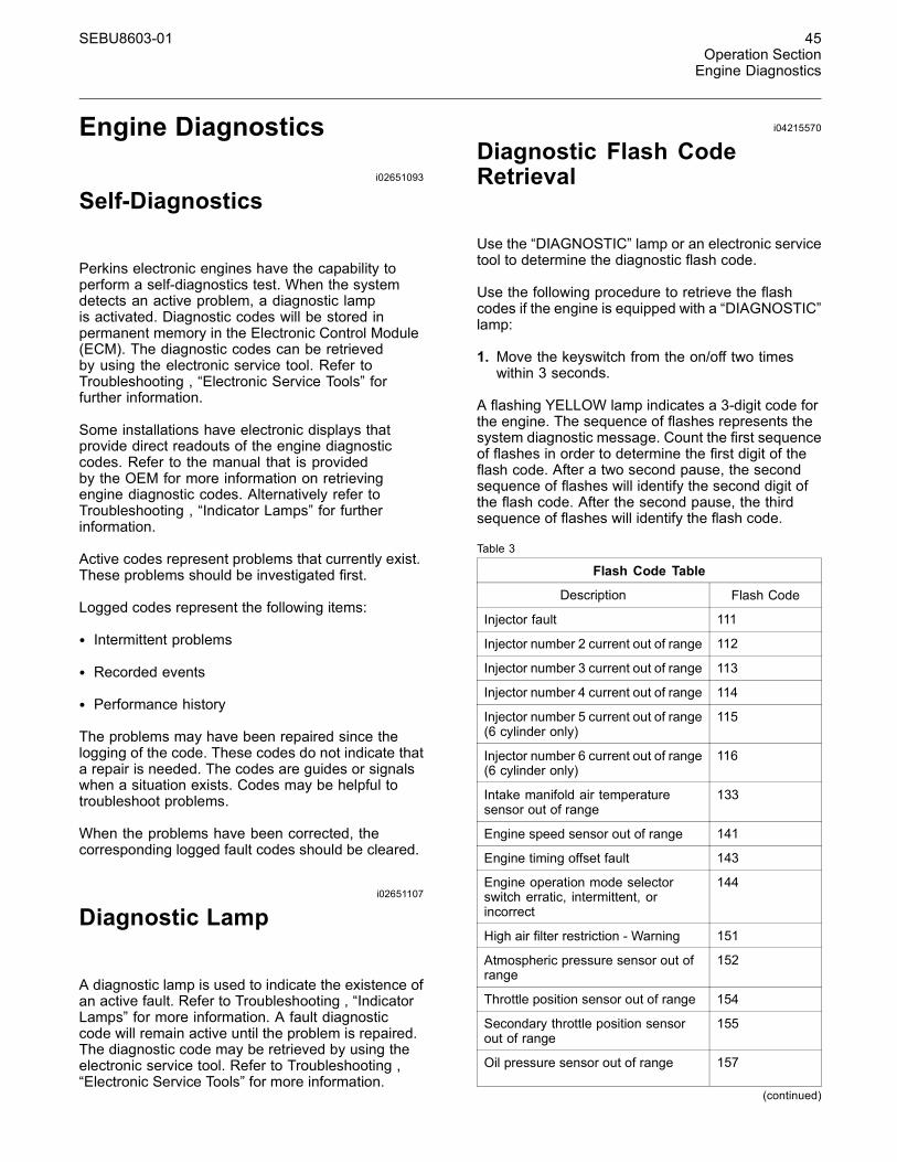
Diagnostic Flash CodeRetrieval
Use the “DIAGNOSTIC” lamp or an electronic servicetool to determine the diagnostic flash code.
Use the following procedure to retrieve the flashcodes if the engine is equipped with a “DIAGNOSTIC”lamp:
1. Move the keyswitch from the on/off two timeswithin 3 seconds.
A flashing YELLOW lamp indicates a 3-digit code forthe engine. The sequence of flashes represents thesystem diagnostic message. Count the first sequenceof flashes in order to determine the first digit of theflash code. After a two second pause, the secondsequence of flashes will identify the second digit ofthe flash code. After the second pause, the thirdsequence of flashes will identify the flash code.
Table 3
Flash Code Table
Description Flash Code
Injector fault 111
Injector number 2 current out of range 112
Injector number 3 current out of range 113
Injector number 4 current out of range 114
Injector number 5 current out of range(6 cylinder only)
115
Injector number 6 current out of range(6 cylinder only)
116
Intake manifold air temperaturesensor out of range
133
Engine speed sensor out of range 141
Engine timing offset fault 143
Engine operation mode selectorswitch erratic, intermittent, orincorrect
144
High air filter restriction - Warning 151
Atmospheric pressure sensor out ofrange
152
Throttle position sensor out of range 154
Secondary throttle position sensorout of range
155
Oil pressure sensor out of range 157
(continued)
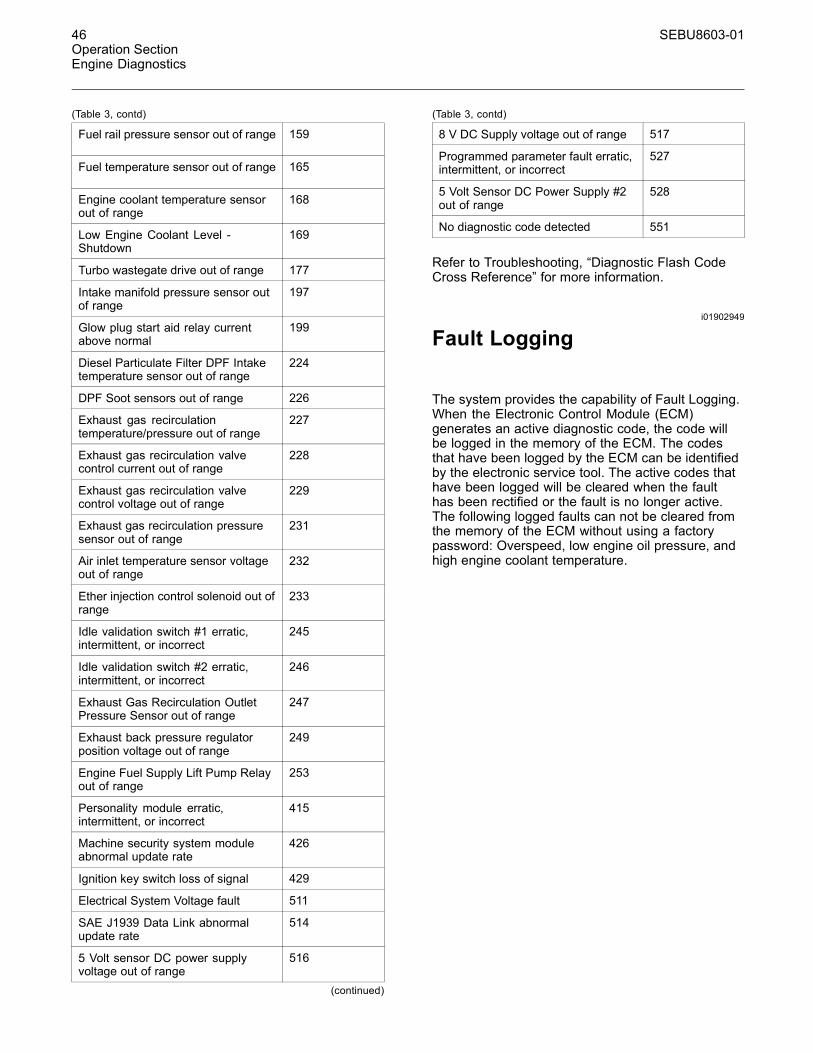
46 SEBU8603-01Operation SectionEngine Diagnostics
(Table 3, contd)
Fuel rail pressure sensor out of range 159
Fuel temperature sensor out of range 165
Engine coolant temperature sensorout of range
168
Low Engine Coolant Level -Shutdown
169
Turbo wastegate drive out of range 177
Intake manifold pressure sensor outof range
197
Glow plug start aid relay currentabove normal
199
Diesel Particulate Filter DPF Intaketemperature sensor out of range
224
DPF Soot sensors out of range 226
Exhaust gas recirculationtemperature/pressure out of range
227
Exhaust gas recirculation valvecontrol current out of range
228
Exhaust gas recirculation valvecontrol voltage out of range
229
Exhaust gas recirculation pressuresensor out of range
231
Air inlet temperature sensor voltageout of range
232
Ether injection control solenoid out ofrange
233
Idle validation switch #1 erratic,intermittent, or incorrect
245
Idle validation switch #2 erratic,intermittent, or incorrect
246
Exhaust Gas Recirculation OutletPressure Sensor out of range
247
Exhaust back pressure regulatorposition voltage out of range
249
Engine Fuel Supply Lift Pump Relayout of range
253
Personality module erratic,intermittent, or incorrect
415
Machine security system moduleabnormal update rate
426
Ignition key switch loss of signal 429
Electrical System Voltage fault 511
SAE J1939 Data Link abnormalupdate rate
514
5 Volt sensor DC power supplyvoltage out of range
516
(continued)
(Table 3, contd)
8 V DC Supply voltage out of range 517
Programmed parameter fault erratic,intermittent, or incorrect
527
5 Volt Sensor DC Power Supply #2out of range
528
No diagnostic code detected 551
Refer to Troubleshooting, “Diagnostic Flash CodeCross Reference” for more information.
i01902949
Fault Logging
The system provides the capability of Fault Logging.When the Electronic Control Module (ECM)generates an active diagnostic code, the code willbe logged in the memory of the ECM. The codesthat have been logged by the ECM can be identifiedby the electronic service tool. The active codes thathave been logged will be cleared when the faulthas been rectified or the fault is no longer active.The following logged faults can not be cleared fromthe memory of the ECM without using a factorypassword: Overspeed, low engine oil pressure, andhigh engine coolant temperature.
SEBU8603-01 47Operation SectionEngine Diagnostics
i03554534
Engine Operation with ActiveDiagnostic Codes
If a diagnostic lamp illuminates during normal engineoperation, the system has identified a situation thatis not within the specification. Use electronic servicetools to check the active diagnostic codes.
Note: If the customer has selected “DERATE” and ifthere is a low oil pressure condition, the ElectronicControl Module (ECM) will limit the engine poweruntil the problem is corrected. If the oil pressure iswithin the normal range, the engine may be operatedat the rated speed and load. However, maintenanceshould be performed as soon as possible.
The active diagnostic code should be investigated.The cause of the problem should be corrected assoon as possible. If the cause of the active diagnosticcode is repaired and there is only one activediagnostic code, the diagnostic lamp will turn off.
Operation of the engine and performance of theengine can be limited as a result of the activediagnostic code that is generated. Accelerationrates may be significantly slower. Refer to theTroubleshooting Guide for more information on therelationship between these active diagnostic codesand engine performance.
i01902995
Engine Operation withIntermittent Diagnostic Codes
If a diagnostic lamp illuminates during normal engineoperation and the diagnostic lamp shuts off, anintermittent fault may have occurred. If a fault hasoccurred, the fault will be logged into the memory ofthe Electronic Control Module (ECM).
In most cases, it is not necessary to stop the enginebecause of an intermittent code. However, theoperator should retrieve the logged fault codesand the operator should reference the appropriateinformation in order to identify the nature of the event.The operator should log any observation that couldhave caused the lamp to light.
• Low power
• Limits of the engine speed
• Excessive smoke, etc
This information can be useful to help troubleshootthe situation. The information can also be used forfuture reference. For more information on diagnosticcodes, refer to the Troubleshooting Guide for thisengine.
i04217251
Configuration Parameters
The engine electronic control module (ECM) hastwo types of configuration parameters. The systemconfiguration parameters and the customer specifiedparameters.
The electronic service tool is required in order to alterthe configuration parameters.
System Configuration ParametersSystem configuration parameters affect the emissionsof the engine or the power of the engine. Systemconfiguration parameters are programmed at thefactory. Normally, system configuration parameterswould never require changing through the lifeof the engine. System configuration parametersmust be reprogrammed if an ECM is replaced.System configuration parameters do not requirereprogrammed if the ECM software is changed.Factory passwords are required to change theseparameters.
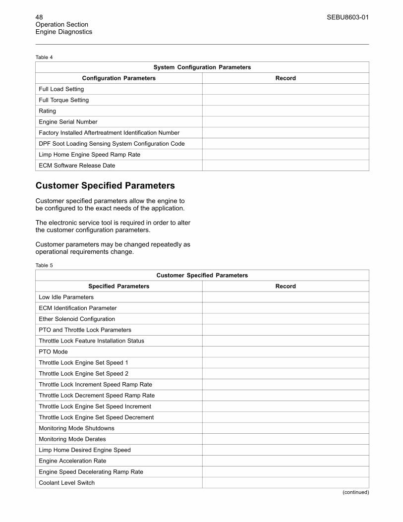
48 SEBU8603-01Operation SectionEngine Diagnostics
Table 4
System Configuration Parameters
Configuration Parameters Record
Full Load Setting
Full Torque Setting
Rating
Engine Serial Number
Factory Installed Aftertreatment Identification Number
DPF Soot Loading Sensing System Configuration Code
Limp Home Engine Speed Ramp Rate
ECM Software Release Date
Customer Specified ParametersCustomer specified parameters allow the engine tobe configured to the exact needs of the application.
The electronic service tool is required in order to alterthe customer configuration parameters.
Customer parameters may be changed repeatedly asoperational requirements change.
Table 5
Customer Specified Parameters
Specified Parameters Record
Low Idle Parameters
ECM Identification Parameter
Ether Solenoid Configuration
PTO and Throttle Lock Parameters
Throttle Lock Feature Installation Status
PTO Mode
Throttle Lock Engine Set Speed 1
Throttle Lock Engine Set Speed 2
Throttle Lock Increment Speed Ramp Rate
Throttle Lock Decrement Speed Ramp Rate
Throttle Lock Engine Set Speed Increment
Throttle Lock Engine Set Speed Decrement
Monitoring Mode Shutdowns
Monitoring Mode Derates
Limp Home Desired Engine Speed
Engine Acceleration Rate
Engine Speed Decelerating Ramp Rate
Coolant Level Switch(continued)
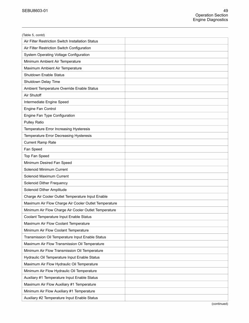
SEBU8603-01 49Operation SectionEngine Diagnostics
(Table 5, contd)
Air Filter Restriction Switch Installation Status
Air Filter Restriction Switch Configuration
System Operating Voltage Configuration
Minimum Ambient Air Temperature
Maximum Ambient Air Temperature
Shutdown Enable Status
Shutdown Delay Time
Ambient Temperature Override Enable Status
Air Shutoff
Intermediate Engine Speed
Engine Fan Control
Engine Fan Type Configuration
Pulley Ratio
Temperature Error Increasing Hysteresis
Temperature Error Decreasing Hysteresis
Current Ramp Rate
Fan Speed
Top Fan Speed
Minimum Desired Fan Speed
Solenoid Minimum Current
Solenoid Maximum Current
Solenoid Dither Frequency
Solenoid Dither Amplitude
Charge Air Cooler Outlet Temperature Input Enable
Maximum Air Flow Charge Air Cooler Outlet Temperature
Minimum Air Flow Charge Air Cooler Outlet Temperature
Coolant Temperature Input Enable Status
Maximum Air Flow Coolant Temperature
Minimum Air Flow Coolant Temperature
Transmission Oil Temperature Input Enable Status
Maximum Air Flow Transmission Oil Temperature
Minimum Air Flow Transmission Oil Temperature
Hydraulic Oil Temperature Input Enable Status
Maximum Air Flow Hydraulic Oil Temperature
Minimum Air Flow Hydraulic Oil Temperature
Auxiliary #1 Temperature Input Enable Status
Maximum Air Flow Auxiliary #1 Temperature
Minimum Air Flow Auxiliary #1 Temperature
Auxiliary #2 Temperature Input Enable Status(continued)
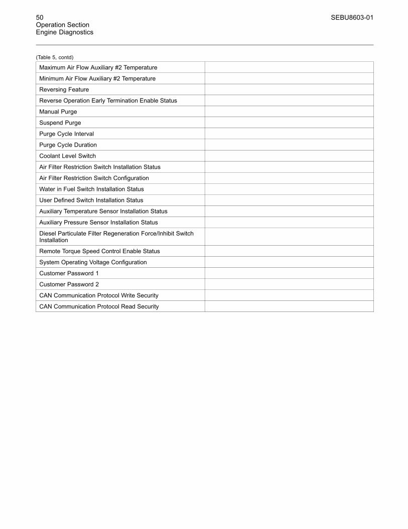
50 SEBU8603-01Operation SectionEngine Diagnostics
(Table 5, contd)
Maximum Air Flow Auxiliary #2 Temperature
Minimum Air Flow Auxiliary #2 Temperature
Reversing Feature
Reverse Operation Early Termination Enable Status
Manual Purge
Suspend Purge
Purge Cycle Interval
Purge Cycle Duration
Coolant Level Switch
Air Filter Restriction Switch Installation Status
Air Filter Restriction Switch Configuration
Water in Fuel Switch Installation Status
User Defined Switch Installation Status
Auxiliary Temperature Sensor Installation Status
Auxiliary Pressure Sensor Installation Status
Diesel Particulate Filter Regeneration Force/Inhibit SwitchInstallation
Remote Torque Speed Control Enable Status
System Operating Voltage Configuration
Customer Password 1
Customer Password 2
CAN Communication Protocol Write Security
CAN Communication Protocol Read Security
SEBU8603-01 51Operation SectionEngine Starting
Engine Startingi03648917
Before Starting Engine
Perform the required daily maintenance and otherperiodic maintenance before the engine is started.Inspect the engine compartment. This inspection canhelp prevent major repairs at a later date. Refer to theOperation and Maintenance Manual, “MaintenanceInterval Schedule” for more information.
• Ensure that the engine has an adequate fuelsupply.
• Open the fuel supply valve (if equipped).
NOTICEAll valves in the fuel return line must be open and fuelsupply lines must be open. Damage to the fuel systemcan occure if fuel lines are closed with the engine inoperation.
If the engine has not been started for several weeks,fuel may have drained from the fuel system. Airmay have entered the filter housing. Also, when fuelfilters have been changed, some air pockets will betrapped in the engine. In these instances, prime thefuel system. Refer to the Operation and MaintenanceManual, “Fuel System - Prime” for more informationon priming the fuel system. Also, check that the fuelspecification is correct and that the fuel conditionis correct. Refer to the Operation and MaintenanceManual, “Fuel Recommendations”.
Engine exhaust contains products of combustionwhich may be harmful to your health. Always startand operate the engine in a well ventilated areaand, if in an enclosed area, vent the exhaust to theoutside.
• Do not start the engine or move any of the controlsif there is a “DO NOT OPERATE” warning tag orsimilar warning tag attached to the start switch orto the controls.
• Reset all of the shutoffs or alarm components.
• Ensure that any driven equipment has beendisengaged. Minimize electrical loads or removeany electrical loads.
i04084389
Starting the Engine
Note: Do not adjust the engine speed control duringstart-up. The electronic control module (ECM) willcontrol the engine speed during start-up.
Starting the Engine1. Disengage any equipment that is driven by theengine.
2. Turn the keyswitch to the RUN position. Leave thekeyswitch in the RUN position until the warninglight for the glow plugs is extinguished.
Note: During the key on, the indicator lamps willbe illuminated for 2 seconds in order to check lampoperation. If any of the lamps do not illuminate,replace the bulb.
3. When the warning light for the glow plugs isextinguished, turn the keyswitch to the STARTposition in order to engage the electric startingmotor and crank the engine.
Note: The operating period of the warning light forthe glow plugs will change due to the temperatureof the engine.
NOTICEDo not engage the starting motor when flywheel isturning. Do not start the engine under load.
If the engine fails to start within 30 seconds, releasethe starter switch or button and wait two minutes toallow the starting motor to cool before attempting tostart the engine again.
4. Allow the keyswitch to return to the RUN positionafter the engine starts.
5. Repeat step 2 through step 4 if the engine failsto start.
i03570564
Cold Weather Starting
Do not use aerosol types of starting aids such asether. Such use could result in an explosion andpersonal injury.
52 SEBU8603-01Operation SectionEngine Starting
Startability will be improved at temperatures below−18 °C (0 °F) from the use of a jacket water heateror extra battery capacity.
When Group 2 diesel fuel is used, the following itemsprovide a means of minimizing starting problemsand fuel problems in cold weather: Engine oil panheaters, jacket water heaters, fuel heaters, and fuelline insulation.
Use the procedure that follows for cold weatherstarting.
Note: Do not adjust the engine speed control duringstart-up. The electronic control module (ECM) willcontrol the engine speed during start-up.
1. Disengage any driven equipment.
2. Turn the keyswitch to the RUN position. Leave thekeyswitch in the RUN position until the warninglight for the glow plugs is extinguished.
NOTICEDo not engage the starting motor when flywheel isturning. Do not start the engine under load.
If the engine fails to start within 30 seconds, releasethe starter switch or button and wait two minutes toallow the starting motor to cool before attempting tostart the engine again.
3. When the warning light for the glow plugs isextinguished turn the keyswitch to the STARTposition in order to engage the electric startingmotor and crank the engine.
Note: The operating period of the warning light forthe glow plugs will change due to the temperatureof the engine.
4. Allow the keyswitch to return to the RUN positionafter the engine starts.
5. Repeat step 2 through step 4 if the engine failsto start.
Note: The engine should not be “raced” in order tospeed up the warm up process.
6. Allow the engine to idle for three to five minutes, orallow the engine to idle until the water temperatureindicator begins to rise. When idling after theengine has started in cold weather, increase theengine rpm from 1000 to 1200 rpm. This willwarm up the engine more quickly. Maintainingan elevated low idle speed for extended periodswill be easier with the installation of a handthrottle. Allow the white smoke to disperse beforeproceeding with normal operation.
7. Operate the engine at low load until all systemsreach operating temperature. Check the gaugesduring the warm-up period.
i03663103
Starting with Jump StartCables
Improper jump start cable connections can causean explosion resulting in personal injury.
Prevent sparks near the batteries. Sparks couldcause vapors to explode. Do not allow jump startcable ends to contact each other or the engine.
Note: If it is possible, first diagnose the reason forthe starting failure. Refer to Troubleshooting, “EngineWill Not Crank and Engine Cranks But Will Not Start”for further information. Make any necessary repairs.If the engine will not start only due to the conditionof the battery, either charge the battery, or start theengine by using another battery with jump startcables.The condition of the battery can be rechecked afterthe engine has been switched OFF.
NOTICEUsing a battery source with the same voltage as theelectric starting motor. Use ONLY equal voltage forjump starting. The use of higher voltage will damagethe electrical system.
Do not reverse the battery cables. The alternator canbe damaged. Attach ground cable last and removefirst.
Turn all electrical accessories OFF before attachingthe jump start cables.
Ensure that the main power switch is in the OFF posi-tion before attaching the jump start cables to the en-gine being started.
1. Turn the start switch on the stalled engine to theOFF position. Turn off all the engine's accessories.
2. Connect one positive end of the jump start cableto the positive cable terminal of the dischargedbattery. Connect the other positive end of the jumpstart cable to the positive cable terminal of theelectrical source.
SEBU8603-01 53Operation SectionEngine Starting
3. Connect one negative end of the jump start cableto the negative cable terminal of the electricalsource. Connect the other negative end of thejump start cable to the engine block or to thechassis ground. This procedure helps to preventpotential sparks from igniting the combustiblegases that are produced by some batteries.
Note: The engine ECM must be powered before thestarting motor is operated or damage can occur.
4. Start the engine in the normal operating procedure.Refer to this Operation and Maintenance Manual,“Starting the Engine”.
5. Immediately after the engine is started, disconnectthe jump start cables in reverse order.
After jump starting, the alternator may not be able tofully recharge batteries that are severely discharged.The batteries must be replaced or charged to theproper voltage with a battery charger after the engineis stopped. Many batteries which are consideredunusable are still rechargeable. Refer to Operationand Maintenance Manual, “Battery - Replace” andTesting and Adjusting Manual, “Battery - Test”.
i02330138
After Starting Engine
Note: In ambient temperatures from 0 to 60°C(32 to 140°F), the warm-up time is approximatelythree minutes. In temperatures below 0°C (32°F),additional warm-up time may be required.
When the engine idles during warm-up, observe thefollowing conditions:
Do not check the high pressure fuel lines with theengine or the starting motor in operation. If youinspect the engine in operation, always use theproper inspection procedure in order to avoid afluid penetration hazard. Refer to Operation andMaintenance Manual, “General hazard Information”.
• Check for any fluid or for any air leaks at idle rpmand at one-half full rpm (no load on the engine)before operating the engine under load. This is notpossible in some applications.
• Allow the engine to idle for three to five minutes, orallow the engine to idle until the water temperatureindicator begins to rise. Check all gauges duringthe warm-up period.
Note: Gauge readings should be observed andthe data should be recorded frequently while theengine is operating. Comparing the data over timewill help to determine normal readings for eachgauge. Comparing data over time will also helpdetect abnormal operating developments. Significantchanges in the readings should be investigated.
54 SEBU8603-01Operation SectionEngine Operation
Engine Operationi03858430
Engine Operation
Proper operation and maintenance are key factorsin obtaining the maximum life and economy ofthe engine. If the directions in the Operation andMaintenance Manual are followed, costs can beminimized and engine service life can be maximized.
The time that is needed for the engine to reachnormal operating temperature can be less than thetime taken for a walk-around inspection of the engine.
The engine can be operated at the rated rpm afterthe engine is started and after the engine reachesoperating temperature. The engine will reach normaloperating temperature sooner during a low enginespeed (rpm) and during a low-power demand. Thisprocedure is more effective than idling the engineat no load. The engine should reach operatingtemperature in a few minutes.
Avoid excess idling. Excessive idling causes carbonbuildup, engine slobber, and soot loading of theDiesel Particulate Filter (DPF). These issues areharmful to the engine.
Gauge readings should be observed and the datashould be recorded frequently while the engineis operating. Comparing the data over time willhelp to determine normal readings for each gauge.Comparing data over time will also help detectabnormal operating developments. Significantchanges in the readings should be investigated.
Reduction of Particulate EmissionsThe Diesel Particulate Filter (DPF) will reduceparticulate emissions. The DPF collects the soot andany ash that is produced by the combustion in theengine. During regeneration, the soot is convertedinto a gas which is released into the atmosphere. TheAsh remains in the DPF.
The temperature of the DPF must be above aparticular value in order for regeneration to occur.The exhaust gas provides heat for the regenerationprocess.
Passive Regeneration – The engine providessufficient exhaust gas temperature for regeneration.
Engine Operation and a DPF
During normal engine operation, the operator of theengine may notice the lack of black smoke from theexhaust system.
Passive regeneration is the process that is usedby the DPF in order to remove soot from the DPF.In some applications, the engine idle speed willautomatically be increased in order to allow passiveregeneration to occur.
SEBU8603-01 55Operation SectionEngine Operation
i04018232
Fuel Conservation Practices
The efficiency of the engine can affect the fueleconomy. Perkins design and technology inmanufacturing provides maximum fuel efficiency inall applications. Follow the recommended proceduresin order to attain optimum performance for the lifeof the engine.
• Avoid spilling fuel.
Fuel expands when the fuel is warmed up. The fuelmay overflow from the fuel tank. Inspect fuel lines forleaks. Repair the fuel lines, as needed.
• Be aware of the properties of the different fuels.Use only the recommended fuels. Refer to theOperations and Maintenance Manual, “FuelRecommendations”for further information.
• Avoid unnecessary idling.
Shut off the engine rather than idle for long periods oftime.
• Observe the service indicator frequently. Keep theair cleaner elements clean.
• Ensure that the turbocharger is operating correctly.For more information refer to this Operation andMaintenance Manual , “Turbocharger - Inspect”
• Maintain a good electrical system.
One faulty battery cell will overwork the alternator.This fault will consume excess power and excessfuel.
• The belt should be in good condition. Refer to theSystems Operation, Testing and Adjusting, “V-BeltTest” for further information.
• Ensure that all of the connections of the hoses aretight. The connections should not leak.
• Ensure that the driven equipment is in goodworking order.
• Cold engines consume excess fuel. Utilize heatfrom the jacket water system and the exhaustsystem, when possible. Keep cooling systemcomponents clean and keep cooling systemcomponents in good repair. Never operate theengine without water temperature regulators.All of these items will help maintain operatingtemperatures.
56 SEBU8603-01Operation SectionEngine Stopping
Engine Stoppingi02334873
Stopping the Engine
NOTICEStopping the engine immediately after it has beenworking under load, can result in overheating and ac-celerated wear of the engine components.
Avoid accelerating the engine prior to shutting it down.
Avoiding hot engine shutdowns will maximize tur-bocharger shaft and bearing life.
Note: Individual applications will have differentcontrol systems. Ensure that the shutoff proceduresare understood. Use the following general guidelinesin order to stop the engine.
1. Remove the load from the engine. Reduce theengine speed (rpm) to low idle. Allow the engineto idle for five minutes in order to cool the engine.
2. Stop the engine after the cool down periodaccording to the shutoff system on the engine andturn the ignition key switch to the OFF position.If necessary, refer to the instructions that areprovided by the OEM.
i01903586
Emergency Stopping
NOTICEEmergency shutoff controls are for EMERGENCY useONLY. DO NOT use emergency shutoff devices orcontrols for normal stopping procedure.
The OEM may have equipped the application withan emergency stop button. For more informationabout the emergency stop button, refer to the OEMinformation.
Ensure that any components for the external systemthat support the engine operation are secured afterthe engine is stopped.
i03648931
After Stopping Engine
Note: Before you check the engine oil, do not operatethe engine for at least 10 minutes in order to allowthe engine oil to return to the oil pan.
Contact with high pressure fuel may cause fluidpenetration and burn hazards. High pressure fu-el spray may cause a fire hazard. Failure to fol-low these inspection, maintenance and service in-structions may cause personal injury or death.
• After the engine has stopped, you must wait for10 minutes in order to allow the fuel pressure tobe purged from the high pressure fuel lines beforeany service or repair is performed on the enginefuel lines. If necessary, perform minor adjustments.Repair any leaks from the low pressure fuelsystem and from the cooling, lubrication or airsystems. Replace any high pressure fuel line thathas leaked. Refer to Disassembly and assemblyManual, “Fuel Injection Lines - Install”.
• Check the crankcase oil level. Maintain the oil levelbetween the “MIN” mark and the “MAX” mark onthe engine oil level gauge.
• If the engine is equipped with a service hour meter,note the reading. Perform the maintenance thatis in the Operation and Maintenance Manual,“Maintenance Interval Schedule”.
• Fill the fuel tank in order to help preventaccumulation of moisture in the fuel. Do not overfillthe fuel tank.
NOTICEOnly use antifreeze/coolant mixtures recommended inthe Refill Capacities and Recommendations topic thatis in this Operation and Maintenance Manual. Failureto do so can cause engine damage.
Pressurized System: Hot coolant can cause seri-ous burns. To open the cooling system filler cap,stop the engine and wait until the cooling systemcomponents are cool. Loosen the cooling systempressure cap slowly in order to relieve the pres-sure.
• Allow the engine to cool. Check the coolant level.
SEBU8603-01 57Operation SectionEngine Stopping
• Check the coolant for correct antifreeze protectionand the correct corrosion protection. Add thecorrect coolant/water mixture, if necessary.
• Perform all required periodic maintenance on alldriven equipment. This maintenance is outlined inthe instructions from the OEM.
58 SEBU8603-01Operation SectionCold Weather Operation
Cold Weather Operationi04321989
Cold Weather Operation
Perkins Diesel Engines can operate effectively incold weather. During cold weather, the starting andthe operation of the diesel engine is dependent onthe following items:
• The type of fuel that is used
• The viscosity of the engine oil
• The operation of the glow plugs
• Optional Cold starting aid
• Battery condition
This section will cover the following information:
• Potential problems that are caused by cold-weatheroperation
• Suggest steps which can be taken in order tominimize starting problems and operating problemswhen the ambient air temperature is between0° to−40 °C (32° to 40 °F).
The operation and maintenance of an engine infreezing temperatures is complex . This complexity isbecause of the following conditions:
• Weather conditions
• Engine applications
Recommendations from your Perkins dealer oryour Perkins distributor are based on past provenpractices. The information that is contained inthis section provides guidelines for cold-weatheroperation.
Hints for Cold Weather Operation• If the engine will start, operate the engine until aminimum operating temperature of 80° C (176° F)is achieved. Achieving operating temperature willhelp prevent the intake valves and exhaust valvesfrom sticking.
• The cooling system and the lubrication systemfor the engine do not lose heat immediately uponshutdown. This means that an engine can be shutdown for a period and the engine can still have theability to start readily.
• Install the correct specification of engine lubricantbefore the beginning of cold weather.
• Check all rubber parts (hoses, fan drive belts,)weekly.
• Check all electrical wiring and connections for anyfraying or damaged insulation.
• Keep all batteries fully charged and warm.
• Fill the fuel tank at the end of each shift.
• Check the air cleaners and the air intake daily.Check the air intake more often when you operatein snow.
• Ensure that the glow plugs are in working order.Refer to Troubleshooting, “Glow Plug Starting Aid-Test”.
Personal injury or property damage can resultfrom alcohol or starting fluids.
Alcohol or startingfluids are highly flammable andtoxic and if improperly stored could result in injuryor property damage.
Do not use aerosol types of starting aids such asether. Such use could result in an explosion andpersonal injury.
• For jump starting with cables in cold weather,refer to the Operation and Maintenance Manual,“Starting with Jump Start Cables.” for instructions.
Viscosity of the Engine LubricationOilCorrect engine oil viscosity is essential. Oil viscosityaffects the amount of torque that is needed tocrank the engine. Refer to this Operation andMaintenance Manual, “Fluid Recommendations” forthe recommended viscosity of oil.
Recommendations for the CoolantProvide cooling system protection for the lowestexpected outside temperature. Refer to this Operationand Maintenance Manual, “Fluid Recommendations”for the recommended coolant mixture.
SEBU8603-01 59Operation Section
Cold Weather Operation
In cold weather, check the coolant often for thecorrect glycol concentration in order to ensureadequate freeze protection.
Engine Block Heaters
Engine block heaters (if equipped) heat theengine jacket water that surrounds the combustionchambers. This heat provides the following functions:
• Startability is improved.
• Warm up time is reduced.
An electric block heater can be activated once theengine is stopped. A block heater can be 110 V dc or240 V dc. The output can be 750/1000W. Consultyour Perkins dealer or your Perkins distributor formore information.
Idling the EngineWhen idling after the engine is started in coldweather, increase the engine rpm from 1000 to 1200rpm. This idling will warm up the engine more quickly.Maintaining an elevated low idle speed for extendedperiods will be easier with the installation of a handthrottle. The engine should not be “raced” in order tospeed up the warm-up process.
While the engine is idling, the application of a lightload (parasitic load) will assist in achieving theminimum operating temperature. The minimumoperating temperature is 80° C (176° F).
Recommendations for CoolantWarm UpWarm up an engine that has cooled below normaloperating temperatures due to inactivity. This warm-up should be performed before the engine isreturned to full operation. During operation in verycold temperature conditions, damage to enginevalve mechanisms can result from engine operationfor short intervals. This damage can happen if theengine is started and the engine is stopped manytimes without being operated in order to warm upcompletely.
When the engine is operated below normal operatingtemperatures, fuel and oil are not completely burnedin the combustion chamber. This fuel and oil causessoft carbon deposits to form on the valve stems.Generally, the deposits do not cause problems andthe deposits are burned off during operation atnormal engine operating temperatures.
When starting and stopping an engine manytimes without being operated in order to warm upcompletely, the carbon deposits become thicker.This starting and stopping can cause the followingproblems:
• Free operation of the valves is prevented.
• Valves become stuck.
• Pushrods may become bent.
• Other damage to valve train components canresult.
For this reason, when the engine is started,the engine must be operated until the coolanttemperature is 80° C (176° F) minimum. Carbondeposits on the valve stems will be kept at a minimumand the free operation of the valves and the valvecomponents will be maintained.
The engine must be thoroughly warmed in orderto keep other engine parts in better condition. Theservice life of the engine will be generally extended.Lubrication will be improved. There will be less acidand less sludge in the oil. This condition will providelonger service life for the engine bearings, the pistonrings, and other parts. However, limit unnecessaryidle time to 10 minutes in order to reduce wear andunnecessary fuel consumption.
The Water Temperature Regulator andInsulated Heater Lines
The engine is equipped with a water temperatureregulator. When the engine coolant is below thecorrect operating temperature, jacket water circulatesthrough the engine cylinder block and into theengine cylinder head. The coolant then returns to thecylinder block via an internal passage that bypassesthe valve of the coolant temperature regulator. Thisensures that coolant flows around the engine undercold operating conditions. The water temperatureregulator begins to open when the engine jacketwater has reached the correct minimum operatingtemperature. As the jacket water coolant temperaturerises above the minimum operating temperature, thewater temperature regulator opens further allowingmore coolant through the radiator to dissipate excessheat.
The progressive opening of the water temperatureregulator operates the progressive closing of thebypass passage between the cylinder block andhead. This action ensures maximum coolant flowto the radiator in order to achieve maximum heatdissipation.

60 SEBU8603-01Operation SectionCold Weather Operation
Note: Do not restrict the air flow. Restriction ofthe air flow can damage the fuel system. Perkinsdiscourages the use of all air flow restrictiondevices such as radiator shutters. Restriction of theair flow can result in the following: high exhausttemperatures, power loss, excessive fan usage, andreduction in fuel economy.
A cab heater is beneficial in very cold weather. Thefeed from the engine and the return lines from thecab should be insulated in order to reduce heat lossto the outside air.
Recommendation for Crankcase BreatherProtection
Crankcase ventilation gases contain a large quantityof water vapor. This water vapor can freeze incold ambient conditions and can plug or damagethe crankcase ventilation system. If the engine isoperated in temperatures below −25° C (−13° F),measures must be taken to prevent freezing andplugging of the breather system. Insulated hoses anda heated canister assembly should be installed.
Consult with your Perkins dealer or your Perkinsdistributer for the recommended breathercomponents for operation from −25° to -40°C(−13° to -72.°F).
i02685960
Fuel and the Effect from ColdWeather
Note: Only use grades of fuel that are recommendedby Perkins. Refer to this Operation and MaintenanceManual, “Fluid Recommendations”.
The following components provide a means ofminimizing problems in cold weather:
• Glow plugs (if equipped)
• Engine coolant heaters, which may be an OEMoption
• Fuel heaters, which may be an OEM option
• Fuel line insulation, which may be an OEM option
The cloud point is a temperature that allows waxcrystals to form in the fuel. These crystals can causethe fuel filters to plug.
The pour point is the temperature when diesel fuelwill thicken. The diesel fuel becomes more resistantto flow through fuel lines, fuel filters,and fuel pumps.
Be aware of these facts when diesel fuel ispurchased. Consider the average ambient airtemperature for the engine's application. Engines thatare fueled in one climate may not operate well if theengines are moved to another climate. Problems canresult due to changes in temperature.
Before troubleshooting for low power or for poorperformance in the winter, check the fuel for waxing.
Low temperature fuels may be available for engineoperation at temperatures below 0 °C (32 °F). Thesefuels limit the formation of wax in the fuel at lowtemperatures.
For more information on cold weather operation, referto the Operation and Maintenance Manual, “ColdWeather Operation and Fuel Related Components inCold Weather”.
SEBU8603-01 61Operation Section
Cold Weather Operation
i02323237
Fuel Related Components inCold Weather
Fuel TanksCondensation can form in partially filled fuel tanks.Top off the fuel tanks after you operate the engine.
Fuel tanks should contain some provision for drainingwater and sediment from the bottom of the tanks.
Some fuel tanks use supply pipes that allow waterand sediment to settle below the end of the fuelsupply pipe.
Some fuel tanks use supply lines that take fueldirectly from the bottom of the tank. If the engine isequipped with this system, regular maintenance ofthe fuel system filter is important.
Drain the water and sediment from any fuel storagetank at the following intervals: weekly, serviceintervals, and refueling of the fuel tank. This will helpprevent water and/or sediment from being pumpedfrom the fuel storage tank and into the engine fueltank.
Fuel FiltersA primary fuel filter is installed between the fueltank and the engine fuel inlet. After you changethe fuel filter, always prime the fuel system in orderto remove air bubbles from the fuel system. Referto the Operation and Maintenance Manual in theMaintenance Section for more information on primingthe fuel system.
The location of a primary fuel filter is important in coldweather operation. The primary fuel filter and the fuelsupply line are the most common components thatare affected by cold fuel.
Fuel HeatersNote: The OEM may equip the application with fuelheaters. If this is the case, the temperature of the fuelmust not exceed 73 °C (163 °F) at the fuel transferpump.
For more information about fuel heaters (if equipped),refer to the OEM information.
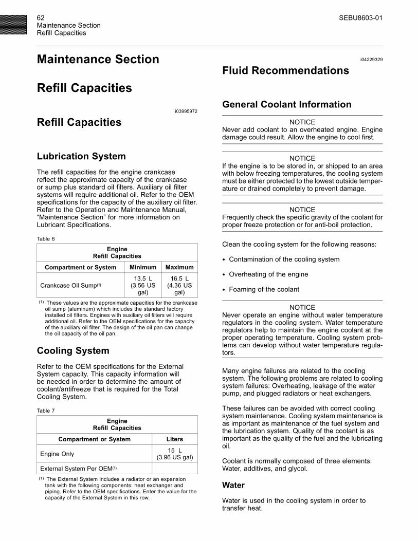
62 SEBU8603-01Maintenance SectionRefill Capacities
Maintenance Section
Refill Capacitiesi03995972
Refill Capacities
Lubrication SystemThe refill capacities for the engine crankcasereflect the approximate capacity of the crankcaseor sump plus standard oil filters. Auxiliary oil filtersystems will require additional oil. Refer to the OEMspecifications for the capacity of the auxiliary oil filter.Refer to the Operation and Maintenance Manual,“Maintenance Section” for more information onLubricant Specifications.
Table 6
EngineRefill Capacities
Compartment or System Minimum Maximum
Crankcase Oil Sump(1)13.5 L(3.56 USgal)
16.5 L(4.36 USgal)
(1) These values are the approximate capacities for the crankcaseoil sump (aluminum) which includes the standard factoryinstalled oil filters. Engines with auxiliary oil filters will requireadditional oil. Refer to the OEM specifications for the capacityof the auxiliary oil filter. The design of the oil pan can changethe oil capacity of the oil pan.
Cooling SystemRefer to the OEM specifications for the ExternalSystem capacity. This capacity information willbe needed in order to determine the amount ofcoolant/antifreeze that is required for the TotalCooling System.
Table 7
EngineRefill Capacities
Compartment or System Liters
Engine Only 15 L(3.96 US gal)
External System Per OEM(1)
(1) The External System includes a radiator or an expansiontank with the following components: heat exchanger andpiping. Refer to the OEM specifications. Enter the value for thecapacity of the External System in this row.
i04229329
Fluid Recommendations
General Coolant Information
NOTICENever add coolant to an overheated engine. Enginedamage could result. Allow the engine to cool first.
NOTICEIf the engine is to be stored in, or shipped to an areawith below freezing temperatures, the cooling systemmust be either protected to the lowest outside temper-ature or drained completely to prevent damage.
NOTICEFrequently check the specific gravity of the coolant forproper freeze protection or for anti-boil protection.
Clean the cooling system for the following reasons:
• Contamination of the cooling system
• Overheating of the engine
• Foaming of the coolant
NOTICENever operate an engine without water temperatureregulators in the cooling system. Water temperatureregulators help to maintain the engine coolant at theproper operating temperature. Cooling system prob-lems can develop without water temperature regula-tors.
Many engine failures are related to the coolingsystem. The following problems are related to coolingsystem failures: Overheating, leakage of the waterpump, and plugged radiators or heat exchangers.
These failures can be avoided with correct coolingsystem maintenance. Cooling system maintenance isas important as maintenance of the fuel system andthe lubrication system. Quality of the coolant is asimportant as the quality of the fuel and the lubricatingoil.
Coolant is normally composed of three elements:Water, additives, and glycol.
Water
Water is used in the cooling system in order totransfer heat.
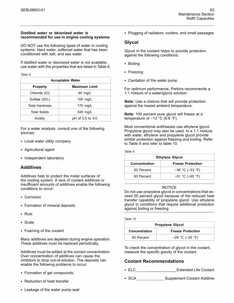
SEBU8603-01 63Maintenance Section
Refill Capacities
Distilled water or deionized water isrecommended for use in engine cooling systems.
DO NOT use the following types of water in coolingsystems: Hard water, softened water that has beenconditioned with salt, and sea water.
If distilled water or deionized water is not available,use water with the properties that are listed in Table 8.
Table 8
Acceptable Water
Property Maximum Limit
Chloride (Cl) 40 mg/L
Sulfate (SO4) 100 mg/L
Total Hardness 170 mg/L
Total Solids 340 mg/L
Acidity pH of 5.5 to 9.0
For a water analysis, consult one of the followingsources:
• Local water utility company
• Agricultural agent
• Independent laboratory
Additives
Additives help to protect the metal surfaces ofthe cooling system. A lack of coolant additives orinsufficient amounts of additives enable the followingconditions to occur:
• Corrosion
• Formation of mineral deposits
• Rust
• Scale
• Foaming of the coolant
Many additives are depleted during engine operation.These additives must be replaced periodically.
Additives must be added at the correct concentration.Over concentration of additives can cause theinhibitors to drop out-of-solution. The deposits canenable the following problems to occur:
• Formation of gel compounds
• Reduction of heat transfer
• Leakage of the water pump seal
• Plugging of radiators, coolers, and small passages
Glycol
Glycol in the coolant helps to provide protectionagainst the following conditions:
• Boiling
• Freezing
• Cavitation of the water pump
For optimum performance, Perkins recommends a1:1 mixture of a water/glycol solution.
Note: Use a mixture that will provide protectionagainst the lowest ambient temperature.
Note: 100 percent pure glycol will freeze at atemperature of −13 °C (8.6 °F).
Most conventional antifreezes use ethylene glycol.Propylene glycol may also be used. In a 1:1 mixturewith water, ethylene and propylene glycol providesimilar protection against freezing and boiling. Referto Table 9 and refer to table 10.
Table 9
Ethylene Glycol
Concentration Freeze Protection
50 Percent −36 °C (−33 °F)
60 Percent −51 °C (−60 °F)
NOTICEDo not use propylene glycol in concentrations that ex-ceed 50 percent glycol because of the reduced heattransfer capability of propylene glycol. Use ethyleneglycol in conditions that require additional protectionagainst boiling or freezing.
Table 10
Propylene Glycol
Concentration Freeze Protection
50 Percent −29 °C (−20 °F)
To check the concentration of glycol in the coolant,measure the specific gravity of the coolant.
Coolant Recommendations
• ELC____________________________Extended Life Coolant
• SCA___________________Supplement Coolant Additive
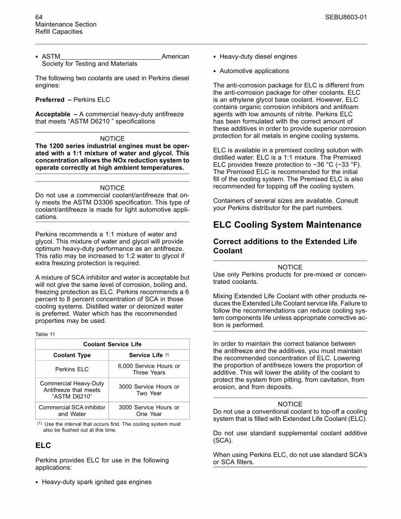
64 SEBU8603-01Maintenance SectionRefill Capacities
• ASTM__________________________________________AmericanSociety for Testing and Materials
The following two coolants are used in Perkins dieselengines:
Preferred – Perkins ELC
Acceptable – A commercial heavy-duty antifreezethat meets “ASTM D6210 ” specifications
NOTICEThe 1200 series industrial engines must be oper-ated with a 1:1 mixture of water and glycol. Thisconcentration allows the NOx reduction system tooperate correctly at high ambient temperatures.
NOTICEDo not use a commercial coolant/antifreeze that on-ly meets the ASTM D3306 specification. This type ofcoolant/antifreeze is made for light automotive appli-cations.
Perkins recommends a 1:1 mixture of water andglycol. This mixture of water and glycol will provideoptimum heavy-duty performance as an antifreeze.This ratio may be increased to 1:2 water to glycol ifextra freezing protection is required.
A mixture of SCA inhibitor and water is acceptable butwill not give the same level of corrosion, boiling and,freezing protection as ELC. Perkins recommends a 6percent to 8 percent concentration of SCA in thosecooling systems. Distilled water or deionized wateris preferred. Water which has the recommendedproperties may be used.
Table 11
Coolant Service Life
Coolant Type Service Life (1)
Perkins ELC 6,000 Service Hours orThree Years
Commercial Heavy-DutyAntifreeze that meets“ASTM D6210”
3000 Service Hours orTwo Year
Commercial SCA inhibitorand Water
3000 Service Hours orOne Year
(1) Use the interval that occurs first. The cooling system mustalso be flushed out at this time.
ELC
Perkins provides ELC for use in the followingapplications:
• Heavy-duty spark ignited gas engines
• Heavy-duty diesel engines
• Automotive applications
The anti-corrosion package for ELC is different fromthe anti-corrosion package for other coolants. ELCis an ethylene glycol base coolant. However, ELCcontains organic corrosion inhibitors and antifoamagents with low amounts of nitrite. Perkins ELChas been formulated with the correct amount ofthese additives in order to provide superior corrosionprotection for all metals in engine cooling systems.
ELC is available in a premixed cooling solution withdistilled water. ELC is a 1:1 mixture. The PremixedELC provides freeze protection to −36 °C (−33 °F).The Premixed ELC is recommended for the initialfill of the cooling system. The Premixed ELC is alsorecommended for topping off the cooling system.
Containers of several sizes are available. Consultyour Perkins distributor for the part numbers.
ELC Cooling System Maintenance
Correct additions to the Extended LifeCoolant
NOTICEUse only Perkins products for pre-mixed or concen-trated coolants.
Mixing Extended Life Coolant with other products re-duces the Extended Life Coolant service life. Failure tofollow the recommendations can reduce cooling sys-tem components life unless appropriate corrective ac-tion is performed.
In order to maintain the correct balance betweenthe antifreeze and the additives, you must maintainthe recommended concentration of ELC. Loweringthe proportion of antifreeze lowers the proportion ofadditive. This will lower the ability of the coolant toprotect the system from pitting, from cavitation, fromerosion, and from deposits.
NOTICEDo not use a conventional coolant to top-off a coolingsystem that is filled with Extended Life Coolant (ELC).
Do not use standard supplemental coolant additive(SCA).
When using Perkins ELC, do not use standard SCA'sor SCA filters.
SEBU8603-01 65Maintenance Section
Refill Capacities
ELC Cooling System Cleaning
Note: If the cooling system is already using ELC,cleaning agents are not required to be used atthe specified coolant change interval. Cleaningagents are only required if the system has beencontaminated by the addition of some other type ofcoolant or by cooling system damage.
Clean water is the only cleaning agent that is requiredwhen ELC is drained from the cooling system.
Before the cooling system is filled, the heater control(if equipped) must be set to the hot position. Referto the OEM in order to set the heater control. Afterthe cooling system is drained and the cooling systemis refilled, operate the engine until the coolant levelreaches the normal operating temperature anduntil the coolant level stabilizes. As needed, addthe coolant mixture in order to fill the system to thespecified level.
Changing to Perkins ELC
To change from heavy-duty antifreeze to the PerkinsELC, perform the following steps:
NOTICECare must be taken to ensure that all fluids arecontained during performance of inspection, main-tenance, testing, adjusting and the repair of theproduct. Be prepared to collect the fluid with suitablecontainers before opening any compartment or dis-assembling any component containing fluids.
Dispose of all fluids according to local regulations andmandates.
1. Drain the coolant into a suitable container.
2. Dispose of the coolant according to localregulations.
3. Flush the system with clean water in order toremove any debris.
4. Use an appropriate cleaner to clean the system.Follow the instruction on the label.
5. Drain the cleaner into a suitable container. Flushthe cooling system with clean water.
6. Fill the cooling system with clean water andoperate the engine until the engine is warmed to49° to 66°C (120° to 150°F).
NOTICEIncorrect or incomplete flushing of the cooling systemcan result in damage to copper and other metal com-ponents.
To avoid damage to the cooling system, make sure tocompletely flush the cooling system with clear water.Continue to flush the system until all the signs of thecleaning agent are gone.
7. Drain the cooling system into a suitable containerand flush the cooling system with clean water.
Note: The cooling system cleaner must be thoroughlyflushed from the cooling system. Cooling systemcleaner that is left in the system will contaminate thecoolant. The cleaner may also corrode the coolingsystem.
8. Repeat Steps 6 and repeat steps 7 until thesystem is completely clean.
9. Fill the cooling system with the Perkins PremixedELC.
ELC Cooling System Contamination
NOTICEMixing ELC with other products reduces the effective-ness of the ELC and shortens the ELC service life.Use only Perkins Products for premixed or concen-trate coolants. Failure to follow these recommenda-tions can result in shortened cooling system compo-nent life.
ELC cooling systems can withstand contamination toa maximum of 10 percent of conventional heavy-dutyantifreeze or SCA. If the contamination exceeds 10percent of the total system capacity, perform ONE ofthe following procedures:
• Drain the cooling system into a suitable container.Dispose of the coolant according to localregulations. Flush the system with clean water. Fillthe system with the Perkins ELC.
• Drain a portion of the cooling system into a suitablecontainer according to local regulations. Then,fill the cooling system with premixed ELC. Thisprocedure should lower the contamination to lessthan 10 percent.
• Maintain the system as a conventional Heavy-DutyCoolant. Treat the system with an SCA. Changethe coolant at the interval that is recommended forthe conventional Heavy-Duty Coolant.
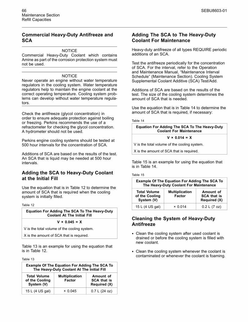
66 SEBU8603-01Maintenance SectionRefill Capacities
Commercial Heavy-Duty Antifreeze andSCA
NOTICECommercial Heavy-Duty Coolant which containsAmine as part of the corrosion protection system mustnot be used.
NOTICENever operate an engine without water temperatureregulators in the cooling system. Water temperatureregulators help to maintain the engine coolant at thecorrect operating temperature. Cooling system prob-lems can develop without water temperature regula-tors.
Check the antifreeze (glycol concentration) inorder to ensure adequate protection against boilingor freezing. Perkins recommends the use of arefractometer for checking the glycol concentration.A hydrometer should not be used.
Perkins engine cooling systems should be tested at500 hour intervals for the concentration of SCA.
Additions of SCA are based on the results of the test.An SCA that is liquid may be needed at 500 hourintervals.
Adding the SCA to Heavy-Duty Coolantat the Initial Fill
Use the equation that is in Table 12 to determine theamount of SCA that is required when the coolingsystem is initially filled.
Table 12
Equation For Adding The SCA To The Heavy-DutyCoolant At The Initial Fill
V × 0.045 = X
V is the total volume of the cooling system.
X is the amount of SCA that is required.
Table 13 is an example for using the equation thatis in Table 12.
Table 13
Example Of The Equation For Adding The SCA ToThe Heavy-Duty Coolant At The Initial Fill
Total Volumeof the CoolingSystem (V)
MultiplicationFactor
Amount ofSCA that isRequired (X)
15 L (4 US gal) × 0.045 0.7 L (24 oz)
Adding The SCA to The Heavy-DutyCoolant For Maintenance
Heavy-duty antifreeze of all types REQUIRE periodicadditions of an SCA.
Test the antifreeze periodically for the concentrationof SCA. For the interval, refer to the Operationand Maintenance Manual, “Maintenance IntervalSchedule” (Maintenance Section). Cooling SystemSupplemental Coolant Additive (SCA) Test/Add.
Additions of SCA are based on the results of thetest. The size of the cooling system determines theamount of SCA that is needed.
Use the equation that is in Table 14 to determine theamount of SCA that is required, if necessary:
Table 14
Equation For Adding The SCA To The Heavy-DutyCoolant For Maintenance
V × 0.014 = X
V is the total volume of the cooling system.
X is the amount of SCA that is required.
Table 15 is an example for using the equation thatis in Table 14.
Table 15
Example Of The Equation For Adding The SCA ToThe Heavy-Duty Coolant For Maintenance
Total Volumeof the CoolingSystem (V)
MultiplicationFactor
Amount ofSCA that isRequired (X)
15 L (4 US gal) × 0.014 0.2 L (7 oz)
Cleaning the System of Heavy-DutyAntifreeze
• Clean the cooling system after used coolant isdrained or before the cooling system is filled withnew coolant.
• Clean the cooling system whenever the coolant iscontaminated or whenever the coolant is foaming.

SEBU8603-01 67Maintenance Section
Refill Capacities
i04156282
Fluid Recommendations
General Lubricant InformationBecause of government regulations regarding thecertification of exhaust emissions from the engine,the lubricant recommendations must be followed.
• API_____________________American Petroleum Institute
• SAE___________________________________________Society OfAutomotive Engineers Inc.
• ACEA__________________________________Association desConstructers European Automobiles.
• ECF-3_______________________Engine Crankcase Fluid
Licensing
The Engine Oil Licensing and Certification Systemby the American Petroleum Institute (API) andthe Association des Constructers EuropeanAutomobilesand (ACRA) is recognized by Perkins.For detailed information about this system, see thelatest edition of the “API publication No. 1509”.Engine oils that bear the API symbol are authorizedby API.
g01987816Illustration 36
Typical API symbol
Terminology
Certain abbreviations follow the nomenclature of“SAE J754”. Some classifications follow “SAE J183”abbreviations, and some classifications follow the“EMA Recommended Guideline on Diesel EngineOil”. In addition to Perkins definitions, there are otherdefinitions that will be of assistance in purchasinglubricants. Recommended oil viscosities can be foundin this publication, “Fluid Recommendations/EngineOil” topic (Maintenance Section).
Engine Oil
Commercial Oils
NOTICEPerkins require the use of the following specifica-tion of engine oil. Failure to use the appropriatespecification of engine oil will reduce the life ofyour engine. Failure to use the appropriate spec-ification of engine oil will also reduce the life ofyour aftertreatment system.
Table 16
Classifications for the 1200 Series Industrial Engine
Oil Specification
API CJ-4ACEA E9ECF-3
API CJ-4 and ACEA E9 oil categories have thefollowing chemical limits:
• 1 percent maximum sulfated ash
• 0.12 percent maximum phosphorous
• 0. 4 percent maximum sulfur
The chemical limits were developed in orderto maintain the expected life of the engineaftertreatment system. The performance of theengine aftertreatment system can be adverselyaffected if oil that is not specified in table 16 is used.
The life of your Aftertreatment system is defined bythe accumulation of ash on the surface of the filter.Ash is the inert part of the particulate matter. Thesystem is designed in order to collect this particulatematter. There is a very small percentage of particulatematter that is left behind as the soot is burnt. Thismatter will eventually block the filter, causing lossof performance and increased fuel consumption.Most of the ash comes from the engine oil which isgradually consumed during normal operation. Thisash is passes through the exhaust. To meet thedesigned life of the product, the use of the appropriateengine oil is essential. The oil specification that islisted in table 16 has low ash content.
Maintenance intervals for engines that usebiodiesel – The oil change interval can be adverselyaffected by the use of biodiesel. Use oil analysis inorder to monitor the condition of the engine oil. Useoil analysis also in order to determine the oil changeinterval that is optimum.
Note: These engine oils are not approved byPerkins and these engine oils must not beused:CC, CD, CD-2, CF-4, CG-4, CH-4, and CI-4.
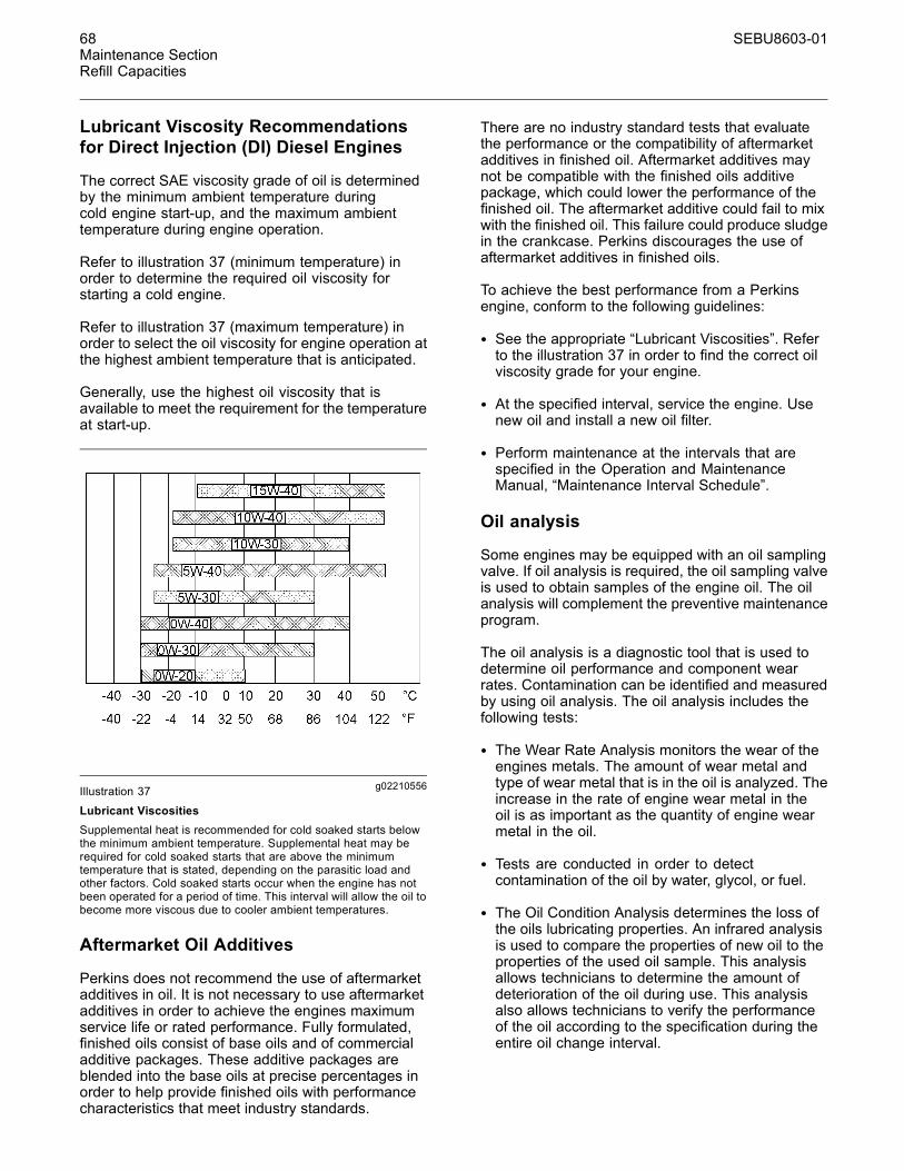
68 SEBU8603-01Maintenance SectionRefill Capacities
Lubricant Viscosity Recommendationsfor Direct Injection (DI) Diesel Engines
The correct SAE viscosity grade of oil is determinedby the minimum ambient temperature duringcold engine start-up, and the maximum ambienttemperature during engine operation.
Refer to illustration 37 (minimum temperature) inorder to determine the required oil viscosity forstarting a cold engine.
Refer to illustration 37 (maximum temperature) inorder to select the oil viscosity for engine operation atthe highest ambient temperature that is anticipated.
Generally, use the highest oil viscosity that isavailable to meet the requirement for the temperatureat start-up.
g02210556Illustration 37
Lubricant ViscositiesSupplemental heat is recommended for cold soaked starts belowthe minimum ambient temperature. Supplemental heat may berequired for cold soaked starts that are above the minimumtemperature that is stated, depending on the parasitic load andother factors. Cold soaked starts occur when the engine has notbeen operated for a period of time. This interval will allow the oil tobecome more viscous due to cooler ambient temperatures.
Aftermarket Oil Additives
Perkins does not recommend the use of aftermarketadditives in oil. It is not necessary to use aftermarketadditives in order to achieve the engines maximumservice life or rated performance. Fully formulated,finished oils consist of base oils and of commercialadditive packages. These additive packages areblended into the base oils at precise percentages inorder to help provide finished oils with performancecharacteristics that meet industry standards.
There are no industry standard tests that evaluatethe performance or the compatibility of aftermarketadditives in finished oil. Aftermarket additives maynot be compatible with the finished oils additivepackage, which could lower the performance of thefinished oil. The aftermarket additive could fail to mixwith the finished oil. This failure could produce sludgein the crankcase. Perkins discourages the use ofaftermarket additives in finished oils.
To achieve the best performance from a Perkinsengine, conform to the following guidelines:
• See the appropriate “Lubricant Viscosities”. Referto the illustration 37 in order to find the correct oilviscosity grade for your engine.
• At the specified interval, service the engine. Usenew oil and install a new oil filter.
• Perform maintenance at the intervals that arespecified in the Operation and MaintenanceManual, “Maintenance Interval Schedule”.
Oil analysis
Some engines may be equipped with an oil samplingvalve. If oil analysis is required, the oil sampling valveis used to obtain samples of the engine oil. The oilanalysis will complement the preventive maintenanceprogram.
The oil analysis is a diagnostic tool that is used todetermine oil performance and component wearrates. Contamination can be identified and measuredby using oil analysis. The oil analysis includes thefollowing tests:
• The Wear Rate Analysis monitors the wear of theengines metals. The amount of wear metal andtype of wear metal that is in the oil is analyzed. Theincrease in the rate of engine wear metal in theoil is as important as the quantity of engine wearmetal in the oil.
• Tests are conducted in order to detectcontamination of the oil by water, glycol, or fuel.
• The Oil Condition Analysis determines the loss ofthe oils lubricating properties. An infrared analysisis used to compare the properties of new oil to theproperties of the used oil sample. This analysisallows technicians to determine the amount ofdeterioration of the oil during use. This analysisalso allows technicians to verify the performanceof the oil according to the specification during theentire oil change interval.
SEBU8603-01 69Maintenance Section
Refill Capacities
i04224221
Fluid Recommendations
• Glossary
• ISO International Standards Organization
• ASTM American Society for Testing and Materials
• HFRR High Frequency Reciprocating Rig forLubricity testing of diesel fuels
• FAME Fatty Acid Methyl Esters
• CFR Co-ordinating Fuel Research
• ULSD Ultra Low Sulfur Diesel
• RME Rape Methyl Ester
• SME Soy Methyl Ester
• EPA Environmental Protection Agency of theUnited States
• PPM Parts Per Million
• DPF Diesel Particulate Filter
General Information
NOTICEEvery attempt is made to provide accurate, up-to-dateinformation. By use of this document you agree thatPerkins Engines Company Limited is not responsiblefor errors or omissions.
NOTICEThese recommendations are subject to change with-out notice. Contact your local Perkins distributor forthe most up-to-date recommendations.
Diesel Fuel RequirementsPerkins is not in a position to continuously evaluateand monitor all worldwide distillate diesel fuelspecifications that are published by governments andtechnological societies.
The Perkins Specification for Distillate Diesel Fuelprovides a known reliable baseline in order to judgethe expected performance of distillate diesel fuelsthat are derived from conventional sources.
Satisfactory engine performance is dependent on theuse of a good quality fuel. The use of a good qualityfuel will give the following results: long engine lifeand acceptable exhaust emissions levels. The fuelmust meet the minimum requirements that are statedin the table 17.
NOTICEThe footnotes are of the key part Perkins Specifica-tion for Distillate Diesel Fuel Table. Read ALL of thefootnotes.
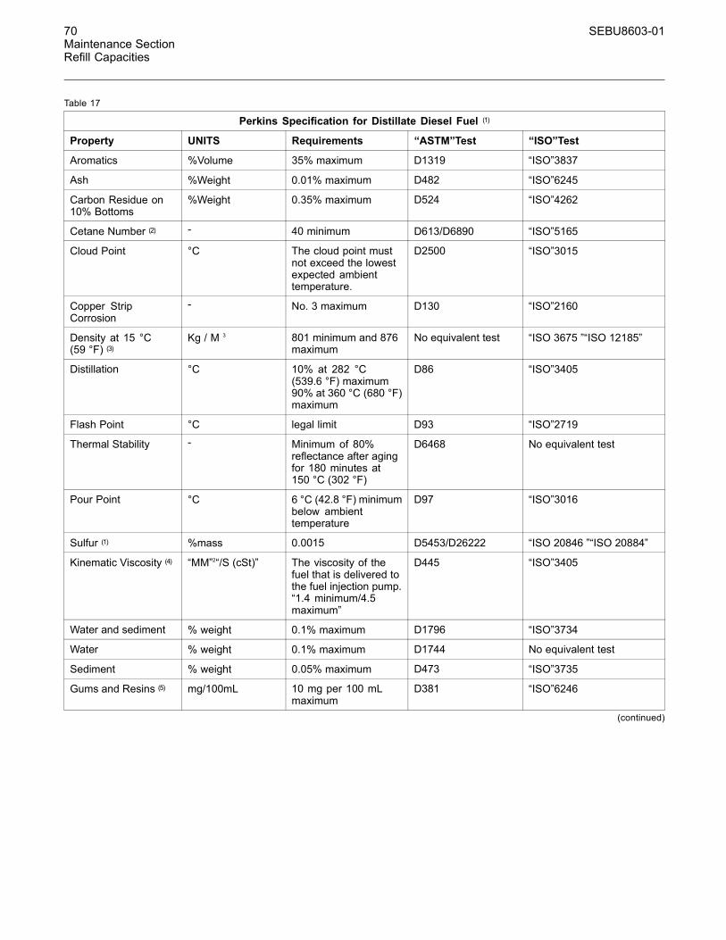
70 SEBU8603-01Maintenance SectionRefill Capacities
Table 17
Perkins Specification for Distillate Diesel Fuel (1)
Property UNITS Requirements “ASTM”Test “ISO”Test
Aromatics %Volume 35% maximum D1319 “ISO”3837
Ash %Weight 0.01% maximum D482 “ISO”6245
Carbon Residue on10% Bottoms
%Weight 0.35% maximum D524 “ISO”4262
Cetane Number (2) - 40 minimum D613/D6890 “ISO”5165
Cloud Point °C The cloud point mustnot exceed the lowestexpected ambienttemperature.
D2500 “ISO”3015
Copper StripCorrosion
- No. 3 maximum D130 “ISO”2160
Density at 15 °C(59 °F) (3)
Kg / M 3 801 minimum and 876maximum
No equivalent test “ISO 3675 ”“ISO 12185”
Distillation °C 10% at 282 °C(539.6 °F) maximum90% at 360 °C (680 °F)maximum
D86 “ISO”3405
Flash Point °C legal limit D93 “ISO”2719
Thermal Stability - Minimum of 80%reflectance after agingfor 180 minutes at150 °C (302 °F)
D6468 No equivalent test
Pour Point °C 6 °C (42.8 °F) minimumbelow ambienttemperature
D97 “ISO”3016
Sulfur (1) %mass 0.0015 D5453/D26222 “ISO 20846 ”“ISO 20884”
Kinematic Viscosity (4) “MM”2“/S (cSt)” The viscosity of thefuel that is delivered tothe fuel injection pump.“1.4 minimum/4.5maximum”
D445 “ISO”3405
Water and sediment % weight 0.1% maximum D1796 “ISO”3734
Water % weight 0.1% maximum D1744 No equivalent test
Sediment % weight 0.05% maximum D473 “ISO”3735
Gums and Resins (5) mg/100mL 10 mg per 100 mLmaximum
D381 “ISO”6246
(continued)
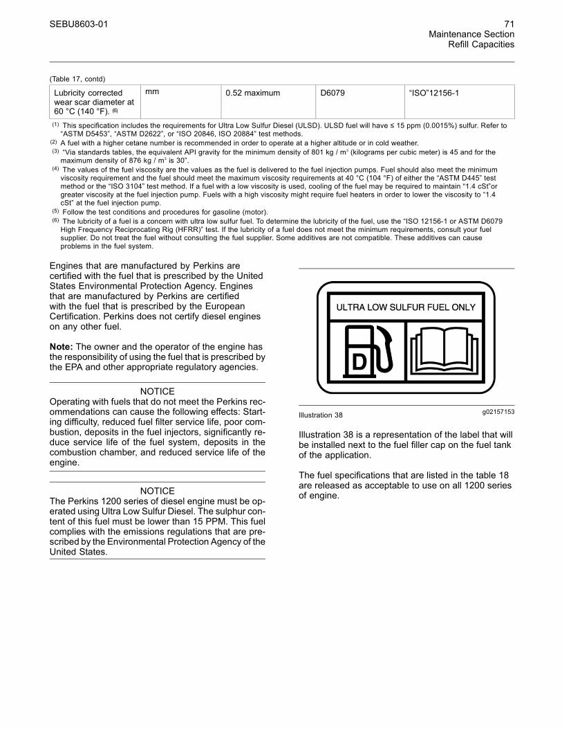
SEBU8603-01 71Maintenance Section
Refill Capacities
(Table 17, contd)
Lubricity correctedwear scar diameter at60 °C (140 °F). (6)
mm 0.52 maximum D6079 “ISO”12156-1
(1) This specification includes the requirements for Ultra Low Sulfur Diesel (ULSD). ULSD fuel will have ≤ 15 ppm (0.0015%) sulfur. Refer to“ASTM D5453”, “ASTM D2622”, or “ISO 20846, ISO 20884” test methods.
(2) A fuel with a higher cetane number is recommended in order to operate at a higher altitude or in cold weather.(3) “Via standards tables, the equivalent API gravity for the minimum density of 801 kg / m3 (kilograms per cubic meter) is 45 and for themaximum density of 876 kg / m3 is 30”.
(4) The values of the fuel viscosity are the values as the fuel is delivered to the fuel injection pumps. Fuel should also meet the minimumviscosity requirement and the fuel should meet the maximum viscosity requirements at 40 °C (104 °F) of either the “ASTM D445” testmethod or the “ISO 3104” test method. If a fuel with a low viscosity is used, cooling of the fuel may be required to maintain “1.4 cSt”orgreater viscosity at the fuel injection pump. Fuels with a high viscosity might require fuel heaters in order to lower the viscosity to “1.4cSt” at the fuel injection pump.
(5) Follow the test conditions and procedures for gasoline (motor).(6) The lubricity of a fuel is a concern with ultra low sulfur fuel. To determine the lubricity of the fuel, use the “ISO 12156-1 or ASTM D6079High Frequency Reciprocating Rig (HFRR)” test. If the lubricity of a fuel does not meet the minimum requirements, consult your fuelsupplier. Do not treat the fuel without consulting the fuel supplier. Some additives are not compatible. These additives can causeproblems in the fuel system.
Engines that are manufactured by Perkins arecertified with the fuel that is prescribed by the UnitedStates Environmental Protection Agency. Enginesthat are manufactured by Perkins are certifiedwith the fuel that is prescribed by the EuropeanCertification. Perkins does not certify diesel engineson any other fuel.
Note: The owner and the operator of the engine hasthe responsibility of using the fuel that is prescribed bythe EPA and other appropriate regulatory agencies.
NOTICEOperating with fuels that do not meet the Perkins rec-ommendations can cause the following effects: Start-ing difficulty, reduced fuel filter service life, poor com-bustion, deposits in the fuel injectors, significantly re-duce service life of the fuel system, deposits in thecombustion chamber, and reduced service life of theengine.
NOTICEThe Perkins 1200 series of diesel engine must be op-erated using Ultra Low Sulfur Diesel. The sulphur con-tent of this fuel must be lower than 15 PPM. This fuelcomplies with the emissions regulations that are pre-scribed by the Environmental Protection Agency of theUnited States.
g02157153Illustration 38
Illustration 38 is a representation of the label that willbe installed next to the fuel filler cap on the fuel tankof the application.
The fuel specifications that are listed in the table 18are released as acceptable to use on all 1200 seriesof engine.
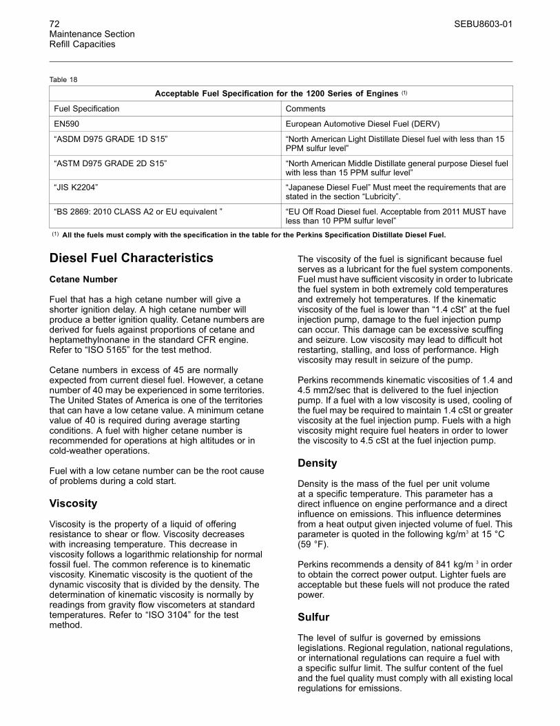
72 SEBU8603-01Maintenance SectionRefill Capacities
Table 18
Acceptable Fuel Specification for the 1200 Series of Engines (1)
Fuel Specification Comments
EN590 European Automotive Diesel Fuel (DERV)
“ASDM D975 GRADE 1D S15” “North American Light Distillate Diesel fuel with less than 15PPM sulfur level”
“ASTM D975 GRADE 2D S15” “North American Middle Distillate general purpose Diesel fuelwith less than 15 PPM sulfur level”
“JIS K2204” “Japanese Diesel Fuel” Must meet the requirements that arestated in the section “Lubricity”.
“BS 2869: 2010 CLASS A2 or EU equivalent ” “EU Off Road Diesel fuel. Acceptable from 2011 MUST haveless than 10 PPM sulfur level”
(1) All the fuels must comply with the specification in the table for the Perkins Specification Distillate Diesel Fuel.
Diesel Fuel CharacteristicsCetane Number
Fuel that has a high cetane number will give ashorter ignition delay. A high cetane number willproduce a better ignition quality. Cetane numbers arederived for fuels against proportions of cetane andheptamethylnonane in the standard CFR engine.Refer to “ISO 5165” for the test method.
Cetane numbers in excess of 45 are normallyexpected from current diesel fuel. However, a cetanenumber of 40 may be experienced in some territories.The United States of America is one of the territoriesthat can have a low cetane value. A minimum cetanevalue of 40 is required during average startingconditions. A fuel with higher cetane number isrecommended for operations at high altitudes or incold-weather operations.
Fuel with a low cetane number can be the root causeof problems during a cold start.
Viscosity
Viscosity is the property of a liquid of offeringresistance to shear or flow. Viscosity decreaseswith increasing temperature. This decrease inviscosity follows a logarithmic relationship for normalfossil fuel. The common reference is to kinematicviscosity. Kinematic viscosity is the quotient of thedynamic viscosity that is divided by the density. Thedetermination of kinematic viscosity is normally byreadings from gravity flow viscometers at standardtemperatures. Refer to “ISO 3104” for the testmethod.
The viscosity of the fuel is significant because fuelserves as a lubricant for the fuel system components.Fuel must have sufficient viscosity in order to lubricatethe fuel system in both extremely cold temperaturesand extremely hot temperatures. If the kinematicviscosity of the fuel is lower than “1.4 cSt” at the fuelinjection pump, damage to the fuel injection pumpcan occur. This damage can be excessive scuffingand seizure. Low viscosity may lead to difficult hotrestarting, stalling, and loss of performance. Highviscosity may result in seizure of the pump.
Perkins recommends kinematic viscosities of 1.4 and4.5 mm2/sec that is delivered to the fuel injectionpump. If a fuel with a low viscosity is used, cooling ofthe fuel may be required to maintain 1.4 cSt or greaterviscosity at the fuel injection pump. Fuels with a highviscosity might require fuel heaters in order to lowerthe viscosity to 4.5 cSt at the fuel injection pump.
Density
Density is the mass of the fuel per unit volumeat a specific temperature. This parameter has adirect influence on engine performance and a directinfluence on emissions. This influence determinesfrom a heat output given injected volume of fuel. Thisparameter is quoted in the following kg/m3 at 15 °C(59 °F).
Perkins recommends a density of 841 kg/m 3 in orderto obtain the correct power output. Lighter fuels areacceptable but these fuels will not produce the ratedpower.
Sulfur
The level of sulfur is governed by emissionslegislations. Regional regulation, national regulations,or international regulations can require a fuel witha specific sulfur limit. The sulfur content of the fueland the fuel quality must comply with all existing localregulations for emissions.
SEBU8603-01 73Maintenance Section
Refill Capacities
Perkins 1200 series diesel engines have beendesigned to operate only with ULSD. By using thetest methods “ASTM D5453, ASTM D2622, or ISO20846 ISO 20884”, the content of sulfur in ULSD fuelmust be below 15 PPM (mg/kg) or 0.0015% mass.
NOTICEUse of diesel fuel with higher than 15 PPM sulphur lim-it in these engines will harm or permanently damageemissions control systems and/or shorten their ser-vice interval.
Lubricity
Lubricity is the capability of the fuel to prevent pumpwear. The fluids lubricity describes the ability of thefluid to reduce the friction between surfaces that areunder load. This ability reduces the damage that iscaused by friction. Fuel injection systems rely on thelubricating properties of the fuel. Until fuel sulfur limitswere mandated, the fuels lubricity was generallybelieved to be a function of fuel viscosity.
The lubricity has particular significance to the currentultra low sulfur fuel, and low aromatic fossil fuels.These fuels are made in order to meet stringentexhaust emissions.
The lubricity of these fuels must not exceed wear scardiameter of 0.52 mm (0.0205 inch). The fuel lubricitytest must be performed on an HFRR, operated at60 °C (140 °F). Refer to “ISO 12156-1 ”.
NOTICEThe fuels system has been qualified with fuel hav-ing lubricity up to 0.52 mm (0.0205 inch) wear scardiameter as tested by “ISO 12156-1”. Fuel with higherwear scar diameter than 0.52 mm (0.0205 inch) willlead to reduced service life and premature failure ofthe fuel system.
Fuel additives can enhance the lubricity of a fuel.Contact your fuel supplier for those circumstanceswhen fuel additives are required. Your fuel suppliercan make recommendations for additives to use, andfor the proper level of treatment.
Distillation
Distillation is an indication of the mixture of differenthydrocarbons in the fuel. A high ratio of light weighthydrocarbons can affect the characteristics ofcombustion.
Recommendation for Biodiesel
Biodiesel is a fuel that can be defined as mono-alkylesters of fatty acids. Biodiesel is a fuel that can bemade from various feedstock. The most commonlyavailable biodiesel in Europe is Rape Methyl Ester(REM). This biodiesel is derived from rapeseedoil. Soy Methyl Ester (SME) is the most commonbiodiesel in the United States. This biodiesel isderived from soybean oil. Soybean oil or rapeseed oilare the primary feedstocks. These fuels are togetherknown as Fatty Acid Methyl Esters (FAME).
Raw pressed vegetable oils are NOT acceptable foruse as a fuel in any concentration in compressionengines. Without esterification, these oils solidify inthe crankcase and the fuel tank. These fuels maynot be compatible with many of the elastomers thatare used in engines that are manufactured today.In original forms, these oils are not suitable for useas a fuel in compression engines. Alternate basestocks for biodiesel may include animal tallow, wastecooking oils, or various other feedstocks. In order touse any of the products that are listed as fuel, the oilmust be esterified.
Fuel made of 100 percent FAME is generally referredto as B100 biodiesel or neat biodiesel.
Biodiesel can be blended with distillate diesel fuel.The blends can be used as fuel. The most commonlyavailable biodiesel blends are B5, which is 5 percentbiodiesel and 95 percent distillate diesel fuel. B20,which is 20 percent biodiesel and 80 percent distillatediesel fuel.
Note: The percentages given are volume-based.
The U.S. distillate diesel fuel specification “ASTMD975-09a” includes up to B5 (5 percent) biodiesel.
European distillate diesel fuel specification EN590:2010 includes up B7 (7 percent) biodiesel.
Note: Engines that are manufactured by Perkinsare certified by use of the prescribed EnvironmentalProtection Agency (EPA) and European Certificationfuels. Perkins does not certify engines on any otherfuel. The user of the engine has the responsibilityof using the correct fuel that is recommended bythe manufacturer and allowed by the EPA and otherappropriate regulatory agencies.
Specification Requirements
The neat biodiesel must conform to the latest“EN14214 or ASTM D6751” (in the USA). Thebiodiesel can only be blended in mixture of up to20% by volume in acceptable mineral diesel fuelmeeting latest edition of “EN590 or ASTM D975 S15”designation.

74 SEBU8603-01Maintenance SectionRefill Capacities
In United States Biodiesel blends of B6 to B20 mustmeet the requirements listed in the latest edition of“ASTM D7467” (B6 to B20) and must be of an APIgravity of 30-45.
In North America biodiesel and biodiesel blendsmust be purchased from the BQ-9000 accreditedproducers and BQ-9000 certified distributors.
In other areas of the world, the use of biodieselthat is BQ-9000 accredited and certified, or that isaccredited and certified by a comparable biodieselquality body to meet similar biodiesel qualitystandards is required.
Engine Service Requirements
Aggressive properties of biodiesel fuel may causedebris in the fuel tank and fuel lines. The aggressiveproperties of biodiesel will clean the fuel tankand fuel lines. This cleaning of the fuel systemcan prematurely block of the fuel filters. Perkinsrecommend that after the initial usage of B20biodiesel blended fuel the fuel filters must be replacedat 50 hours.
Glycerides present in biodiesel fuel will also causefuel filters to become blocked more quickly. Thereforethe regular service interval should be reduced to 250hours.
When biodiesel fuel is used, crank case oil andaftertreatment systems may be influenced. Thisinfluence is due to the chemical composition andcharacteristics of biodiesel fuel, such as density andvolatility, and to chemical contaminants that can bepresent in this fuel, such as alkali and alkaline metals(sodium, potassium, calcium, and magnesium).
• Crankcase oil fuel dilution can be higher whenbiodiesel or biodiesel blends are used. Thisincreased level of fuel dilution when using biodieselor biodiesel blends is related to the typically lowervolatility of biodiesel. In-cylinder emissions controlstrategies utilized in many of the industrial latestengine designs may lead to a higher level ofbiodiesel concentration in the sump. The long-termeffect of biodiesel concentration in crankcase oil iscurrently unknown.
• Perkins recommend the use of oil analysis in orderto check the quality of the engine oil if biodieselfuel is used. Ensure that the level of biodiesel inthe fuel is noted when the oil sample is taken.
Performance Related Issues
Due to the lower energy content than the standarddistillate fuel B20 will cause a power loss in orderof 2 to 4 percent. In addition, over time the powermay deteriorate further due to deposits in the fuelinjectors.
Biodiesel and biodiesel blends are known to causean increase in fuel system deposits, most significantof which are deposits within the fuel injector. Thesedeposits can cause a loss in power due to restrictedor modified fuel injection or cause other functionalissues associated with these deposits.
Note: Perkins T400012 Fuel Cleaner is mosteffective in cleaning and preventing the formationof deposits. Perkins Diesel Fuel Conditioner helpsto limit deposit issues by improving the stability ofbiodiesel and biodiesel blends. For more informationrefer to “Perkins Diesel Fuel System Cleaner”.
Biodiesel fuel contains metal contaminants (sodium,potassium, calcium, and/or magnesium) that form ashproducts upon combustion in the diesel engine. Theash can have an impact on the life and performanceof aftertreatment emissions control devices and canaccumulate in DPF. The ash accumulation may causethe need for more frequent ash service intervals andcause loss of performance
General Requirements
Biodiesel has poor oxidation stability, which can resultin long-term problems in the storage of biodiesel.Biodiesel fuel should be used within 6 months ofmanufacture. Equipment should not be stored withthe B20 biodiesel blends in the fuel system for longerthan 3 months.
Due to poor oxidation stability and other potentialissues, it is strongly recommended that engines withlimited operational time either not use B20 biodieselblends or, while accepting some risk, limit biodieselblend to a maximum of B5. Examples of applicationsthat should limit the use of biodiesel are the following:Standby Generator sets and certain emergencyvehicles.
Perkins strongly recommended that seasonallyoperated engines have the fuel systems, includingfuel tanks, flashed with conventional diesel fuelbefore prolonged shutdown periods. An example ofan application that should seasonally flush the fuelsystem is a combine harvester.
Microbial contamination and growth can causecorrosion in the fuel system and premature pluggingof the fuel filter. Consult your supplier of fuel forassistance in selecting appropriate anti-microbialadditive.
SEBU8603-01 75Maintenance Section
Refill Capacities
Water accelerates microbial contamination andgrowth. When biodiesel is compared to distillatefuels, water is naturally more likely to exist in thebiodiesel. It is therefore essential to check frequentlyand if necessary, drain the water separator.
Materials such as brass, bronze, copper, lead, tin,and zinc accelerate the oxidation process of thebiodiesel fuel. The oxidation process can causedeposits formation therefore these materials must notbe used for fuel tanks and fuel lines.
Fuel for Cold Weather Operation
The European standard “EN590” contains climatedependant requirements and a range of options. Theoptions can be applied differently in each country.There are five classes that are given to arctic climatesand severe winter climates. 0, 1, 2, 3, and 4.
Fuel that complies with “EN590 ” CLASS 4 can beused at temperatures as low as −44 °C (−47.2 °F).Refer to “EN590” for a detailed discretion of thephysical properties of the fuel.
The diesel fuel “ASTM D975 1-D” used in theUnited States of America may be used in very coldtemperatures that are below −18 °C (−0.4 °F).
Aftermarket Fuel Additives
Supplemental diesel fuel additives are not generallyrecommended. This recommendation is due topotential damage to the fuel system or the engine.Your fuel supplier or the fuel manufacturer will addthe appropriate supplemental diesel fuel additives.
Perkins recognizes the fact that additives may berequired in some special circumstances. Contactyour fuel supplier for those circumstances whenfuel additives are required. Your fuel supplier canrecommend the appropriate fuel additive and thecorrect level of treatment.
Note: For the best results, your fuel supplier shouldtreat the fuel when additives are required. The treatedfuel must meet the requirements that are stated intable 17.
Perkins Diesel Fuel System Cleaner
Perkins T400012 Fuel Cleaner is the only fuelcleaner that is recommended by Perkins.
If biodiesel or biodiesel blends of fuel are to beused, Perkins require the use of Perkins fuelcleaner. The use of the fuel is in order to removedeposits within the fuel system that is createdwith the use of biodiesel. For more information onthe use of biodiesel and biodiesel blends refer to“Recommendation for Biodiesel”.
Perkins fuel cleaner will remove deposits that canform in the fuel system with the use of biodiesel andbiodiesel blends. These deposits can create a lossof power and engine performance.
Once the fuel cleaner has been added to the fuel,the deposits within the fuel system are removedafter 30 hours of engine operation. For maximumresults, continue to use the fuel cleaner for up to80 hours. Perkins fuel cleaner can be used on anon-going basis with no adverse impact on engine orfuel system durability.
Details instruction on the rate of which the fuelcleaner must be use are on the container.
Note: Perkins fuel cleaner is compatible with existingand U.S. EPA Tier 4 nonroad certified diesel engineemission control catalysts and particulate filters.Perkins fuel system cleaner contains less than 15ppm of sulfur and is acceptable for use with ULSDfuel.
76 SEBU8603-01Maintenance SectionMaintenance Recommendations
MaintenanceRecommendations
i03648938
System Pressure Release
Coolant System
Pressurized system: Hot coolant can cause seri-ous burn. To open cap, stop engine, wait until ra-diator is cool. Then loosen cap slowly to relievethe pressure.
The engine can have the ability to auto start. Ensurethat the power supply is isolated before any serviceor repair is performed.
To relieve the pressure from the coolant system, turnoff the engine. Allow the cooling system pressure capto cool. Remove the cooling system pressure capslowly in order to relieve pressure.
Fuel SystemTo relieve the pressure from the fuel system, turn offthe engine.
High Pressure Fuel Lines
Contact with high pressure fuel may cause fluidpenetration and burn hazards. High pressure fu-el spray may cause a fire hazard. Failure to fol-low these inspection, maintenance and service in-structions may cause personal injury or death.
The high pressure fuel lines are the fuel lines thatare between the high pressure fuel pump and thehigh pressure fuel manifold and the fuel lines that arebetween the fuel manifold and cylinder head. Thesefuel lines are different from fuel lines on other fuelsystems.
This is because of the following differences:
• The high pressure fuel lines are constantly chargedwith high pressure.
• The internal pressures of the high pressure fuellines are higher than other types of fuel system.
Before any service or repair is performed on theengine fuel lines, perform the following tasks:
1. Stop the engine.
2. Wait for 10 minutes.
Do not loosen the high pressure fuel lines in order toremove air from the fuel system.
Engine OilTo relieve pressure from the lubricating system, turnoff the engine.
i04103081
Welding on Engines withElectronic Controls
NOTICEBecause the strength of the frame may decrease,some manufacturers do not recommend weldingonto a chassis frame or rail. Consult the OEM of theequipment or your Perkins dealer regarding weldingon a chassis frame or rail.
Proper welding procedures are necessary in orderto avoid damage to the engines ECM, sensors, andassociated components. When possible, removethe component from the unit and then weld thecomponent. If removal of the component is notpossible, the following procedure must be followedwhen you weld on a unit equipped with an ElectronicEngine. The following procedure is considered to bethe safest procedure to weld on a component. Thisprocedure should provide a minimum risk of damageto electronic components.
NOTICEDo not ground the welder to electrical componentssuch as the ECM or sensors. Improper grounding cancause damage to the drive train bearings, hydrauliccomponents, electrical components, and other com-ponents.
Clamp the ground cable from the welder to the com-ponent that will be welded. Place the clamp as closeas possible to the weld. This will help reduce the pos-sibility of damage.
Note: Perform the welding in areas that are free fromexplosive hazards.
1. Stop the engine. Turn the switched power to theOFF position.
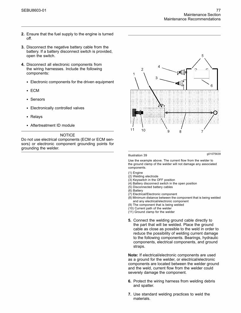
SEBU8603-01 77Maintenance Section
Maintenance Recommendations
2. Ensure that the fuel supply to the engine is turnedoff.
3. Disconnect the negative battery cable from thebattery. If a battery disconnect switch is provided,open the switch.
4. Disconnect all electronic components fromthe wiring harnesses. Include the followingcomponents:
• Electronic components for the driven equipment
• ECM
• Sensors
• Electronically controlled valves
• Relays
• Aftertreatment ID module
NOTICEDo not use electrical components (ECM or ECM sen-sors) or electronic component grounding points forgrounding the welder.
g01075639Illustration 39
Use the example above. The current flow from the welder tothe ground clamp of the welder will not damage any associatedcomponents.
(1) Engine(2) Welding electrode(3) Keyswitch in the OFF position(4) Battery disconnect switch in the open position(5) Disconnected battery cables(6) Battery(7) Electrical/Electronic component(8) Minimum distance between the component that is being welded
and any electrical/electronic component(9) The component that is being welded(10) Current path of the welder(11) Ground clamp for the welder
5. Connect the welding ground cable directly tothe part that will be welded. Place the groundcable as close as possible to the weld in order toreduce the possibility of welding current damageto the following components. Bearings, hydrauliccomponents, electrical components, and groundstraps.
Note: If electrical/electronic components are usedas a ground for the welder, or electrical/electroniccomponents are located between the welder groundand the weld, current flow from the welder couldseverely damage the component.
6. Protect the wiring harness from welding debrisand spatter.
7. Use standard welding practices to weld thematerials.
78 SEBU8603-01Maintenance SectionMaintenance Interval Schedule
i04220877
Maintenance Interval Schedule
When Required
Battery - Replace .................................................. 79Battery or Battery Cable - Disconnect .................. 80Engine - Clean ...................................................... 88Engine Air Cleaner Element (Dual Element) -Clean/Replace .................................................... 89Engine Air Cleaner Element (Single Element) -Inspect/Replace .................................................. 91Engine Oil Sample - Obtain .................................. 96Fuel System - Prime ............................................. 98Severe Service Application - Check ................... 105
Daily
Cooling System Coolant Level - Check ................ 85Driven Equipment - Check .................................... 88Engine Air Cleaner Service Indicator - Inspect ..... 91Engine Air Precleaner - Check/Clean ................... 92Engine Oil Level - Check ...................................... 95Fuel System Primary Filter/Water Separator -Drain ................................................................. 100Walk-Around Inspection ...................................... 107
Every Week
Hoses and Clamps - Inspect/Replace ................ 103
Every 50 Service Hours or Weekly
Fuel Tank Water and Sediment - Drain ............... 102
Every 500 Service Hours
Belt - Inspect ......................................................... 81Engine Oil and Filter - Change ............................. 96
Every 500 Service Hours or 1 Year
Battery Electrolyte Level - Check .......................... 80Cooling System Supplemental Coolant Additive(SCA) - Test/Add ................................................. 86Engine Air Cleaner Element (Dual Element) -Clean/Replace .................................................... 89Engine Air Cleaner Element (Single Element) -Inspect/Replace .................................................. 91Fuel System Primary Filter (Water Separator)Element - Replace .............................................. 98Fuel System Secondary Filter - Replace ............ 101Radiator - Clean .................................................. 104
Every 1000 Service Hours
Water Pump - Inspect ......................................... 108
Every 1500 Service Hours
Engine Crankcase Breather Element - Replace ... 92
Every 2000 Service Hours
Aftercooler Core - Inspect ..................................... 79Engine Mounts - Inspect ....................................... 95Starting Motor - Inspect ...................................... 105Turbocharger - Inspect ........................................ 106
Every 3000 Service Hours
Alternator - Inspect ............................................... 79Alternator and Fan Belts - Replace ....................... 79Belt Tensioner - Inspect ........................................ 81
Every 3000 Service Hours or 2 Years
Cooling System Coolant (Commercial Heavy-Duty) -Change ............................................................... 82Cooling System Water Temperature Regulator -Replace ............................................................... 87
Every 4000 Service Hours
Aftercooler Core - Clean/Test ............................... 79
Every 12 000 Service Hours or 6 Years
Cooling System Coolant (ELC) - Change ............. 83
SEBU8603-01 79Maintenance Section
Aftercooler Core - Clean/Test
i01807350
Aftercooler Core - Clean/Test(Air-To-Air Aftercooler)
The air-to-air aftercooler is OEM installed in manyapplications. Please refer to the OEM specificationsfor information that is related to the aftercooler.
i02322295
Aftercooler Core - Inspect
Note: Adjust the frequency of cleaning according tothe effects of the operating environment.
Inspect the aftercooler for these items: damaged fins,corrosion, dirt, grease, insects, leaves, oil, and otherdebris. Clean the aftercooler, if necessary.
For air-to-air aftercoolers, use the same methods thatare used for cleaning radiators.
Personal injury can result from air pressure.
Personal injury can result without following prop-er procedure.When using pressure air, wear a pro-tective face shield and protective clothing.
Maximum air pressure at the nozzle must be lessthan 205 kPa (30 psi) for cleaning purposes.
After cleaning, start the engine and accelerate theengine to high idle rpm. This will help in the removalof debris and drying of the core. Stop the engine.Use a light bulb behind the core in order to inspectthe core for cleanliness. Repeat the cleaning, ifnecessary.
Inspect the fins for damage. Bent fins may be openedwith a “comb”.
Note: If parts of the aftercooler system are repairedor replaced, a leak test is highly recommended.
Inspect these items for good condition: Welds,mounting brackets, air lines, connections, clamps,and seals. Make repairs, if necessary.
i02322311
Alternator - Inspect
Perkins recommends a scheduled inspection ofthe alternator. Inspect the alternator for looseconnections and correct battery charging. Check theammeter (if equipped) during engine operation inorder to ensure correct battery performance and/orcorrect performance of the electrical system. Makerepairs, as required.
Check the alternator and the battery charger forcorrect operation. If the batteries are correctlycharged, the ammeter reading should be very nearzero. All batteries should be kept charged. Thebatteries should be kept warm because temperatureaffects the cranking power. If the battery is too cold,the battery will not crank the engine. When theengine is not run for long periods of time or if theengine is run for short periods, the batteries may notfully charge. A battery with a low charge will freezemore easily than a battery with a full charge.
i02680137
Alternator and Fan Belts -Replace
Refer to Disassembly and Assembly Manual , “Alternator Belt - Remove and Install”.
i03559623
Battery - Replace
Batteries give off combustible gases which canexplode. A spark can cause the combustible gas-es to ignite. This can result in severe personal in-jury or death.
Ensure proper ventilation for batteries that are inan enclosure. Follow the proper procedures in or-der to help prevent electrical arcs and/or sparksnear batteries. Do not smoke when batteries areserviced.
80 SEBU8603-01Maintenance SectionBattery Electrolyte Level - Check
The battery cables or the batteries should not beremoved with the battery cover in place. The bat-tery cover should be removed before any servic-ing is attempted.
Removing the battery cables or the batteries withthe cover in place may cause a battery explosionresulting in personal injury.
1. Switch the engine to the OFF position. Removeall electrical loads.
2. Turn off any battery chargers. Disconnect anybattery chargers.
3. Ensure that the battery disconnect switch is in theOFF position.
4. Disconnect the NEGATIVE “-” cable from theNEGATIVE “-” battery terminal.
5. Disconnect the POSITIVE “+” cable from thePOSITIVE “+” battery terminal.
Note: Always recycle a battery. Never discard abattery. Dispose of used batteries to an appropriaterecycling facility.
6. Remove the used battery.
7. Install the new battery.
Note: Before the cables are connected, ensure thatthe battery disconnect switch is in the OFF position.
8. Connect the POSITIVE “+” cable to the POSITIVE“+” battery terminal.
9. Connect the NEGATIVE “-” cable to the NEGATIVE“-” battery terminal.
10. Turn the battery disconnect switch to the ONposition.
i02747977
Battery Electrolyte Level -Check
When the engine is not run for long periods of time orwhen the engine is run for short periods, the batteriesmay not fully recharge. Ensure a full charge in orderto help prevent the battery from freezing. If batteriesare correctly charged, the ammeter reading shouldbe very near zero, when the engine is in operation.
All lead-acid batteries contain sulfuric acid whichcan burn the skin and clothing. Always wear a faceshield and protective clothing when working on ornear batteries.
1. Remove the filler caps. Maintain the electrolytelevel to the “FULL” mark on the battery.
If the addition of water is necessary, use distilledwater. If distilled water is not available use cleanwater that is low in minerals. Do not use artificiallysoftened water.
2. Check the condition of the electrolyte with asuitable battery tester.
3. Install the caps.
4. Keep the batteries clean.
Clean the battery case with one of the followingcleaning solutions:
• Use a solution of 0.1 kg (0.2 lb) baking sodaand 1 L (1 qt) of clean water.
• Use a solution of ammonium hydroxide.
Thoroughly rinse the battery case with clean water.
i02323088
Battery or Battery Cable -Disconnect
The battery cables or the batteries should not beremoved with the battery cover in place. The bat-tery cover should be removed before any servic-ing is attempted.
Removing the battery cables or the batteries withthe cover in place may cause a battery explosionresulting in personal injury.
1. Turn the start switch to the OFF position. Turn theignition switch (if equipped) to the OFF positionand remove the key and all electrical loads.
2. Disconnect the negative battery terminal. Ensurethat the cable cannot contact the terminal. Whenfour 12 volt batteries are involved, two negativeconnection must be disconnected.
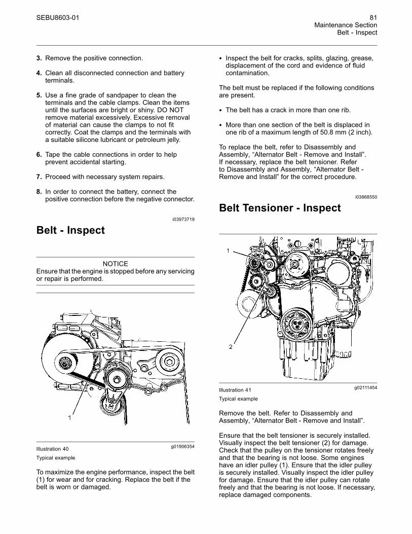
SEBU8603-01 81Maintenance Section
Belt - Inspect
3. Remove the positive connection.
4. Clean all disconnected connection and batteryterminals.
5. Use a fine grade of sandpaper to clean theterminals and the cable clamps. Clean the itemsuntil the surfaces are bright or shiny. DO NOTremove material excessively. Excessive removalof material can cause the clamps to not fitcorrectly. Coat the clamps and the terminals witha suitable silicone lubricant or petroleum jelly.
6. Tape the cable connections in order to helpprevent accidental starting.
7. Proceed with necessary system repairs.
8. In order to connect the battery, connect thepositive connection before the negative connector.
i03973719
Belt - Inspect
NOTICEEnsure that the engine is stopped before any servicingor repair is performed.
g01906354Illustration 40
Typical example
To maximize the engine performance, inspect the belt(1) for wear and for cracking. Replace the belt if thebelt is worn or damaged.
• Inspect the belt for cracks, splits, glazing, grease,displacement of the cord and evidence of fluidcontamination.
The belt must be replaced if the following conditionsare present.
• The belt has a crack in more than one rib.
• More than one section of the belt is displaced inone rib of a maximum length of 50.8 mm (2 inch).
To replace the belt, refer to Disassembly andAssembly, “Alternator Belt - Remove and Install”.If necessary, replace the belt tensioner. Referto Disassembly and Assembly, “Alternator Belt -Remove and Install” for the correct procedure.
i03868550
Belt Tensioner - Inspect
g02111454Illustration 41Typical example
Remove the belt. Refer to Disassembly andAssembly, “Alternator Belt - Remove and Install”.
Ensure that the belt tensioner is securely installed.Visually inspect the belt tensioner (2) for damage.Check that the pulley on the tensioner rotates freelyand that the bearing is not loose. Some engineshave an idler pulley (1). Ensure that the idler pulleyis securely installed. Visually inspect the idler pulleyfor damage. Ensure that the idler pulley can rotatefreely and that the bearing is not loose. If necessary,replace damaged components.
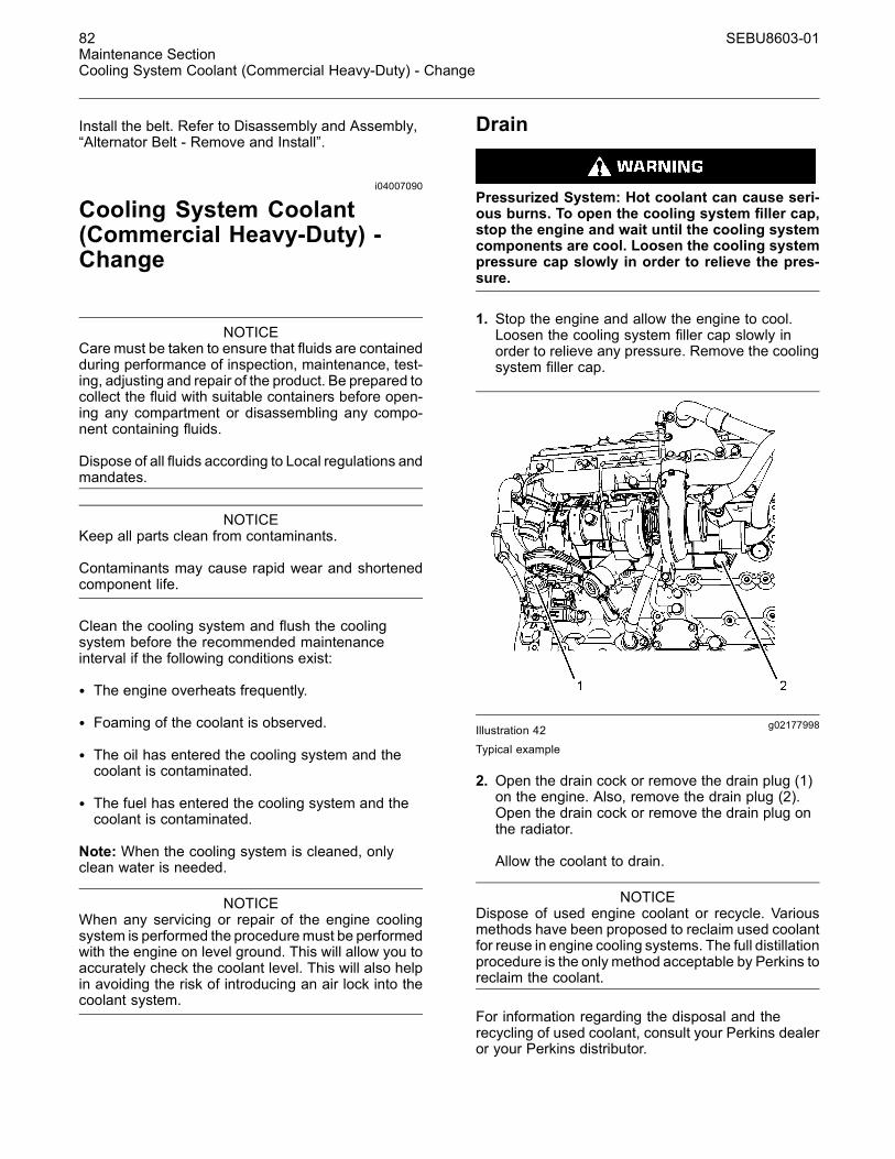
82 SEBU8603-01Maintenance SectionCooling System Coolant (Commercial Heavy-Duty) - Change
Install the belt. Refer to Disassembly and Assembly,“Alternator Belt - Remove and Install”.
i04007090
Cooling System Coolant(Commercial Heavy-Duty) -Change
NOTICECare must be taken to ensure that fluids are containedduring performance of inspection, maintenance, test-ing, adjusting and repair of the product. Be prepared tocollect the fluid with suitable containers before open-ing any compartment or disassembling any compo-nent containing fluids.
Dispose of all fluids according to Local regulations andmandates.
NOTICEKeep all parts clean from contaminants.
Contaminants may cause rapid wear and shortenedcomponent life.
Clean the cooling system and flush the coolingsystem before the recommended maintenanceinterval if the following conditions exist:
• The engine overheats frequently.
• Foaming of the coolant is observed.
• The oil has entered the cooling system and thecoolant is contaminated.
• The fuel has entered the cooling system and thecoolant is contaminated.
Note: When the cooling system is cleaned, onlyclean water is needed.
NOTICEWhen any servicing or repair of the engine coolingsystem is performed the proceduremust be performedwith the engine on level ground. This will allow you toaccurately check the coolant level. This will also helpin avoiding the risk of introducing an air lock into thecoolant system.
Drain
Pressurized System: Hot coolant can cause seri-ous burns. To open the cooling system filler cap,stop the engine and wait until the cooling systemcomponents are cool. Loosen the cooling systempressure cap slowly in order to relieve the pres-sure.
1. Stop the engine and allow the engine to cool.Loosen the cooling system filler cap slowly inorder to relieve any pressure. Remove the coolingsystem filler cap.
g02177998Illustration 42Typical example
2. Open the drain cock or remove the drain plug (1)on the engine. Also, remove the drain plug (2).Open the drain cock or remove the drain plug onthe radiator.
Allow the coolant to drain.
NOTICEDispose of used engine coolant or recycle. Variousmethods have been proposed to reclaim used coolantfor reuse in engine cooling systems. The full distillationprocedure is the only method acceptable by Perkins toreclaim the coolant.
For information regarding the disposal and therecycling of used coolant, consult your Perkins dealeror your Perkins distributor.
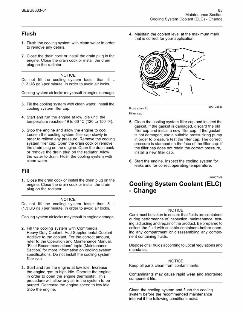
SEBU8603-01 83Maintenance Section
Cooling System Coolant (ELC) - Change
Flush1. Flush the cooling system with clean water in orderto remove any debris.
2. Close the drain cock or install the drain plug in theengine. Close the drain cock or install the drainplug on the radiator.
NOTICEDo not fill the cooling system faster than 5 L(1.3 US gal) per minute, in order to avoid air locks.
Cooling system air locksmay result in engine damage.
3. Fill the cooling system with clean water. Install thecooling system filler cap.
4. Start and run the engine at low idle until thetemperature reaches 49 to 66 °C (120 to 150 °F).
5. Stop the engine and allow the engine to cool.Loosen the cooling system filler cap slowly inorder to relieve any pressure. Remove the coolingsystem filler cap. Open the drain cock or removethe drain plug on the engine. Open the drain cockor remove the drain plug on the radiator. Allowthe water to drain. Flush the cooling system withclean water.
Fill1. Close the drain cock or install the drain plug on theengine. Close the drain cock or install the drainplug on the radiator.
NOTICEDo not fill the cooling system faster than 5 L(1.3 US gal) per minute, in order to avoid air locks.
Cooling system air locksmay result in engine damage.
2. Fill the cooling system with CommercialHeavy-Duty Coolant. Add Supplemental CoolantAdditive to the coolant. For the correct amount,refer to the Operation and Maintenance Manual,“Fluid Recommendations” topic (MaintenanceSection) for more information on cooling systemspecifications. Do not install the cooling systemfiller cap.
3. Start and run the engine at low idle. Increasethe engine rpm to high idle. Operate the enginein order to open the engine thermostat. Thisprocedure will allow any air in the system to bepurged. Decrease the engine speed to low idle.Stop the engine.
4. Maintain the coolant level at the maximum markthat is correct for your application.
g00103639Illustration 43Filler cap
5. Clean the cooling system filler cap and inspect thegasket. If the gasket is damaged, discard the oldfiller cap and install a new filler cap. If the gasketis not damaged, use a suitable pressurizing pumpin order to pressure test the filler cap. The correctpressure is stamped on the face of the filler cap. Ifthe filler cap does not retain the correct pressure,install a new filler cap.
6. Start the engine. Inspect the cooling system forleaks and for correct operating temperature.
i04007109
Cooling System Coolant (ELC)- Change
NOTICECare must be taken to ensure that fluids are containedduring performance of inspection, maintenance, test-ing, adjusting and repair of the product. Be prepared tocollect the fluid with suitable containers before open-ing any compartment or disassembling any compo-nent containing fluids.
Dispose of all fluids according to Local regulations andmandates.
NOTICEKeep all parts clean from contaminants.
Contaminants may cause rapid wear and shortenedcomponent life.
Clean the cooling system and flush the coolingsystem before the recommended maintenanceinterval if the following conditions exist:
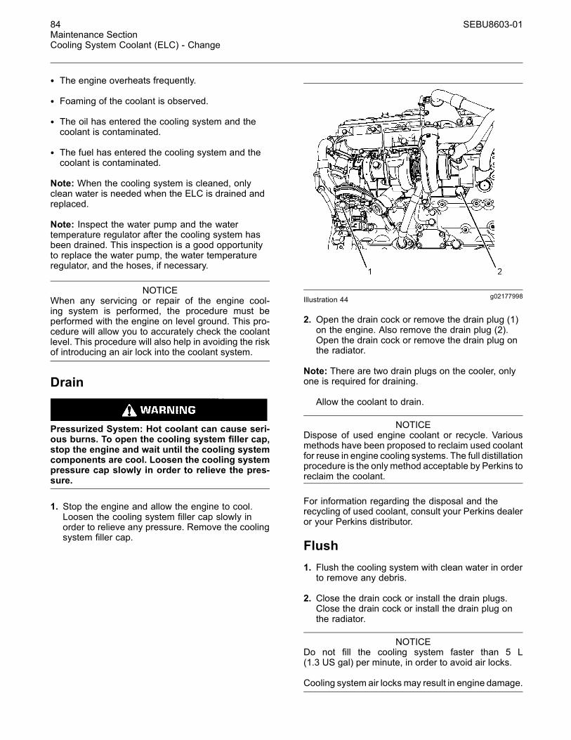
84 SEBU8603-01Maintenance SectionCooling System Coolant (ELC) - Change
• The engine overheats frequently.
• Foaming of the coolant is observed.
• The oil has entered the cooling system and thecoolant is contaminated.
• The fuel has entered the cooling system and thecoolant is contaminated.
Note: When the cooling system is cleaned, onlyclean water is needed when the ELC is drained andreplaced.
Note: Inspect the water pump and the watertemperature regulator after the cooling system hasbeen drained. This inspection is a good opportunityto replace the water pump, the water temperatureregulator, and the hoses, if necessary.
NOTICEWhen any servicing or repair of the engine cool-ing system is performed, the procedure must beperformed with the engine on level ground. This pro-cedure will allow you to accurately check the coolantlevel. This procedure will also help in avoiding the riskof introducing an air lock into the coolant system.
Drain
Pressurized System: Hot coolant can cause seri-ous burns. To open the cooling system filler cap,stop the engine and wait until the cooling systemcomponents are cool. Loosen the cooling systempressure cap slowly in order to relieve the pres-sure.
1. Stop the engine and allow the engine to cool.Loosen the cooling system filler cap slowly inorder to relieve any pressure. Remove the coolingsystem filler cap.
g02177998Illustration 44
2. Open the drain cock or remove the drain plug (1)on the engine. Also remove the drain plug (2).Open the drain cock or remove the drain plug onthe radiator.
Note: There are two drain plugs on the cooler, onlyone is required for draining.
Allow the coolant to drain.
NOTICEDispose of used engine coolant or recycle. Variousmethods have been proposed to reclaim used coolantfor reuse in engine cooling systems. The full distillationprocedure is the only method acceptable by Perkins toreclaim the coolant.
For information regarding the disposal and therecycling of used coolant, consult your Perkins dealeror your Perkins distributor.
Flush1. Flush the cooling system with clean water in orderto remove any debris.
2. Close the drain cock or install the drain plugs.Close the drain cock or install the drain plug onthe radiator.
NOTICEDo not fill the cooling system faster than 5 L(1.3 US gal) per minute, in order to avoid air locks.
Cooling system air locksmay result in engine damage.
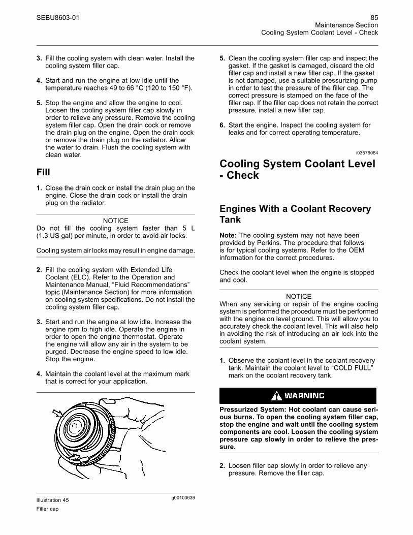
SEBU8603-01 85Maintenance Section
Cooling System Coolant Level - Check
3. Fill the cooling system with clean water. Install thecooling system filler cap.
4. Start and run the engine at low idle until thetemperature reaches 49 to 66 °C (120 to 150 °F).
5. Stop the engine and allow the engine to cool.Loosen the cooling system filler cap slowly inorder to relieve any pressure. Remove the coolingsystem filler cap. Open the drain cock or removethe drain plug on the engine. Open the drain cockor remove the drain plug on the radiator. Allowthe water to drain. Flush the cooling system withclean water.
Fill1. Close the drain cock or install the drain plug on theengine. Close the drain cock or install the drainplug on the radiator.
NOTICEDo not fill the cooling system faster than 5 L(1.3 US gal) per minute, in order to avoid air locks.
Cooling system air locksmay result in engine damage.
2. Fill the cooling system with Extended LifeCoolant (ELC). Refer to the Operation andMaintenance Manual, “Fluid Recommendations”topic (Maintenance Section) for more informationon cooling system specifications. Do not install thecooling system filler cap.
3. Start and run the engine at low idle. Increase theengine rpm to high idle. Operate the engine inorder to open the engine thermostat. Operatethe engine will allow any air in the system to bepurged. Decrease the engine speed to low idle.Stop the engine.
4. Maintain the coolant level at the maximum markthat is correct for your application.
g00103639Illustration 45Filler cap
5. Clean the cooling system filler cap and inspect thegasket. If the gasket is damaged, discard the oldfiller cap and install a new filler cap. If the gasketis not damaged, use a suitable pressurizing pumpin order to test the pressure of the filler cap. Thecorrect pressure is stamped on the face of thefiller cap. If the filler cap does not retain the correctpressure, install a new filler cap.
6. Start the engine. Inspect the cooling system forleaks and for correct operating temperature.
i03576064
Cooling System Coolant Level- Check
Engines With a Coolant RecoveryTankNote: The cooling system may not have beenprovided by Perkins. The procedure that followsis for typical cooling systems. Refer to the OEMinformation for the correct procedures.
Check the coolant level when the engine is stoppedand cool.
NOTICEWhen any servicing or repair of the engine coolingsystem is performed the proceduremust be performedwith the engine on level ground. This will allow you toaccurately check the coolant level. This will also helpin avoiding the risk of introducing an air lock into thecoolant system.
1. Observe the coolant level in the coolant recoverytank. Maintain the coolant level to “COLD FULL”mark on the coolant recovery tank.
Pressurized System: Hot coolant can cause seri-ous burns. To open the cooling system filler cap,stop the engine and wait until the cooling systemcomponents are cool. Loosen the cooling systempressure cap slowly in order to relieve the pres-sure.
2. Loosen filler cap slowly in order to relieve anypressure. Remove the filler cap.

86 SEBU8603-01Maintenance SectionCooling System Supplemental Coolant Additive (SCA) - Test/Add
3. Pour the correct coolant mixture into the tank.Refer to the Operation and Maintenance Manual,“Refill Capacities and Recommendations” forinformation on the correct mixture and type ofcoolant. Refer to the Operation and MaintenanceManual, “Refill Capacities and Recommendations”for the cooling system capacity. Do not fill thecoolant recovery tank above “COLD FULL” mark.
g00103639Illustration 46
4. Clean filler cap and the receptacle. Reinstall thefiller cap and inspect the cooling system for leaks.
Note: The coolant will expand as the coolant heatsup during normal engine operation. The additionalvolume will be forced into the coolant recovery tankduring engine operation. When the engine is stoppedand cool, the coolant will return to the engine.
Engines Without a CoolantRecovery TankCheck the coolant level when the engine is stoppedand cool.
g00285520Illustration 47Cooling system filler cap
Pressurized System: Hot coolant can cause seri-ous burns. To open the cooling system filler cap,stop the engine and wait until the cooling systemcomponents are cool. Loosen the cooling systempressure cap slowly in order to relieve the pres-sure.
1. Remove the cooling system filler cap slowly inorder to relieve pressure.
2. Maintain the coolant level at the maximum markthat is correct for your application. If the engine isequipped with a sight glass, maintain the coolantlevel to the correct level in the sight glass.
3. Clean the cooling system filler cap and inspect thegasket. If the gasket is damaged, discard the oldfiller cap and install a new filler cap. If the gasketis not damaged, use a suitable pressurizing pumpin order to pressure test the filler cap. The correctpressure is stamped on the face of the filler cap. Ifthe filler cap does not retain the correct pressure,install a new filler cap.
4. Inspect the cooling system for leaks.
i03644948
Cooling System SupplementalCoolant Additive (SCA) -Test/Add
Cooling system coolant additive contains alkali.To help prevent personal injury, avoid contact withthe skin and the eyes. Do not drink cooling systemcoolant additive.
Test for SCA Concentration
Heavy-Duty Coolant/Antifreeze and SCA
NOTICEDo not exceed the recommended six percent supple-mental coolant additive concentration.
Use a Coolant Conditioner Test Kit in order to checkthe concentration of the SCA.
SEBU8603-01 87Maintenance Section
Cooling System Water Temperature Regulator - Replace
Add the SCA, If Necessary
NOTICEDo not exceed the recommended amount of sup-plemental coolant additive concentration. Excessivesupplemental coolant additive concentration can formdeposits on the higher temperature surfaces of thecooling system, reducing the engine's heat transfercharacteristics. Reduced heat transfer could causecracking of the cylinder head and other high temper-ature components. Excessive supplemental coolantadditive concentration could also result in radiatortube blockage, overheating, and/or accelerated waterpump seal wear. Never use both liquid supplementalcoolant additive and the spin-on element (if equipped)at the same time. The use of those additives togethercould result in supplemental coolant additive concen-tration exceeding the recommended maximum.
Pressurized System: Hot coolant can cause seri-ous burns. To open the cooling system filler cap,stop the engine and wait until the cooling systemcomponents are cool. Loosen the cooling systempressure cap slowly in order to relieve the pres-sure.
NOTICEWhen any servicing or repair of the engine coolingsystem is performed the proceduremust be performedwith the engine on level ground. This will allow you toaccurately check the coolant level. This will also helpin avoiding the risk of introducing an air lock into thecoolant system.
1. Slowly loosen the cooling system filler cap inorder to relieve the pressure. Remove the coolingsystem filler cap.
Note: Always discard drained fluids according tolocal regulations.
2. If necessary, drain some coolant from the coolingsystem into a suitable container in order to allowspace for the extra SCA.
3. Add the correct amount of SCA. Refer to theOperation and Maintenance Manual, “RefillCapacities and Recommendations” for moreinformation on SCA requirements.
4. Clean the cooling system filler cap and inspect thegasket. If the gasket is damaged, discard the oldfiller cap and install a new filler cap. If the gasketis not damaged, use a suitable pressurizing pumpin order to pressure test the filler cap. The correctpressure is stamped on the face of the filler cap. Ifthe filler cap does not retain the correct pressure,install a new filler cap.
i04020355
Cooling System WaterTemperature Regulator -Replace
Replace the water temperature regulator beforethe water temperature regulator fails. This is arecommended preventive maintenance practice.Replacing the water temperature regulator reducesthe chances for unscheduled downtime. Refer to thisOperation and Maintenance Manual, “MaintenanceInterval Schedule” for the proper maintenanceinterval.
A water temperature regulator that fails in apartially opened position can cause overheating orovercooling of the engine.
A water temperature regulator that fails in the closedposition can cause excessive overheating. Excessiveoverheating could result in cracking of the cylinderhead or piston seizure problems.
A water temperature regulator that fails in the openposition will cause the engine operating temperatureto be too low during partial load operation. Lowengine operating temperatures during partial loadscould cause an excessive carbon buildup inside thecylinders. This excessive carbon buildup could resultin an accelerated wear of the piston rings and wearof the cylinder liner.
88 SEBU8603-01Maintenance SectionDriven Equipment - Check
NOTICEFailure to replace your water temperature regulatoron a regularly scheduled basis could cause severeengine damage.
Perkins engines incorporate a shunt design coolingsystem and require operating the engine with a watertemperature regulator installed.
If the water temperature regulator is installed incor-rectly, the enginemay overheat, causing cylinder headdamage. Ensure that the new water temperature reg-ulator is installed in the original position. Ensure thatthe water temperature regulator vent hole is open.
Do not use liquid gasket material on the gasket orcylinder head surface.
Refer to two articles in the Disassembly andAssembly Manual, “Water Temperature Regulators- Remove and Water Temperature Regulators -Install” for the replacement procedure of the watertemperature regulator, or consult your Perkins dealeror your Perkins distributor.
Note: If only the water temperature regulators arereplaced, drain the coolant from the cooling system toa level that is below the water temperature regulatorhousing.
i02151646
Driven Equipment - Check
Refer to the OEM specifications for more informationon the following maintenance recommendations forthe driven equipment:
• Inspection
• Adjustment
• Lubrication
• Other maintenance recommendations
Perform any maintenance for the driven equipmentwhich is recommended by the OEM.
i03991933
Engine - Clean
Personal injury or death can result from high volt-age.
Moisture can create paths of electrical conductiv-ity.
Make sure that the electrical system is OFF. Lockout the starting controls and tag the controls “DONOT OPERATE”.
NOTICEAccumulated grease and oil on an engine is a fire haz-ard. Keep the engine clean. Remove debris and fluidspills whenever a significant quantity accumulates onthe engine.
Periodic cleaning of the engine is recommended.Steam cleaning the engine will remove accumulatedoil and grease. A clean engine provides the followingbenefits:
• Easy detection of fluid leaks
• Maximum heat transfer characteristics
• Ease of maintenance
Note: Caution must be used in order to preventelectrical components from being damaged byexcessive water when the engine is cleaned.Pressure washers and steam cleaners should not bedirected at any electrical connectors or the junction ofcables into the rear of the connectors. Avoid electricalcomponents such as the alternator, the starter, andthe ECM. Protect the fuel injection pump from fluidsin order to wash the engine.
AftertreatmentDuring the engine cleaning process, ensurethat water or cleaning fluids cannot enter theaftertreatment system. If cleaning fluids enters theaftertreatment system, damage could occur.
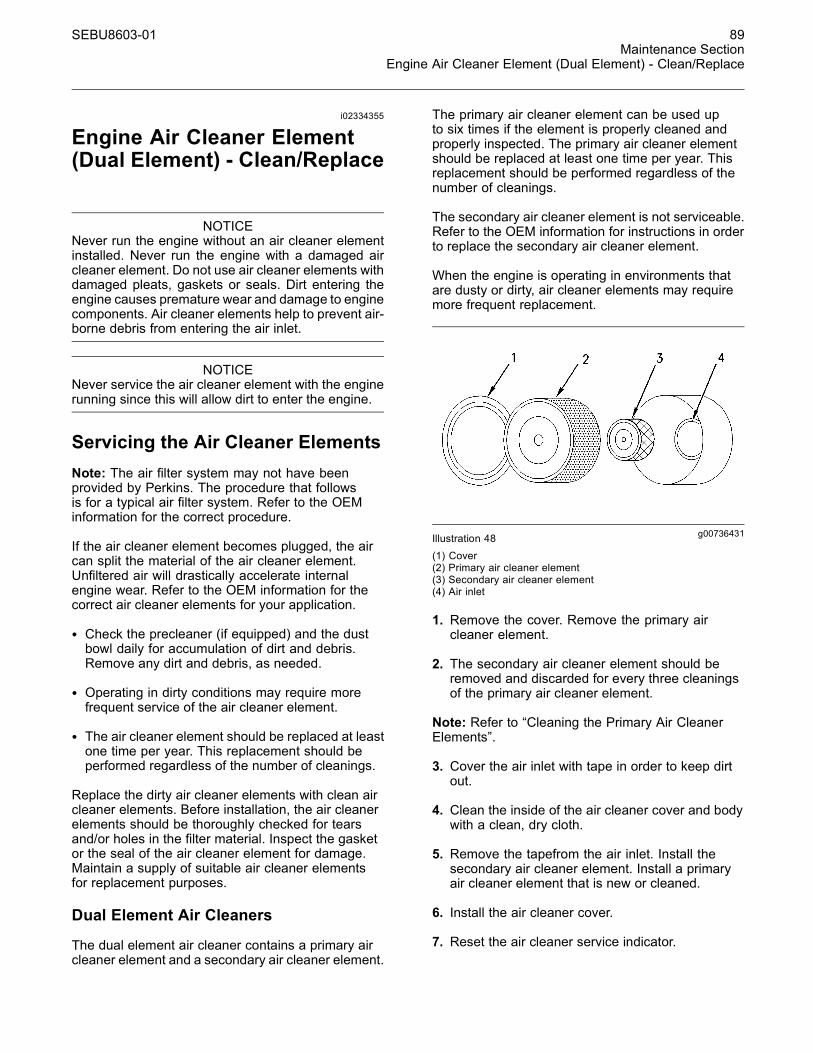
SEBU8603-01 89Maintenance Section
Engine Air Cleaner Element (Dual Element) - Clean/Replace
i02334355
Engine Air Cleaner Element(Dual Element) - Clean/Replace
NOTICENever run the engine without an air cleaner elementinstalled. Never run the engine with a damaged aircleaner element. Do not use air cleaner elements withdamaged pleats, gaskets or seals. Dirt entering theengine causes premature wear and damage to enginecomponents. Air cleaner elements help to prevent air-borne debris from entering the air inlet.
NOTICENever service the air cleaner element with the enginerunning since this will allow dirt to enter the engine.
Servicing the Air Cleaner ElementsNote: The air filter system may not have beenprovided by Perkins. The procedure that followsis for a typical air filter system. Refer to the OEMinformation for the correct procedure.
If the air cleaner element becomes plugged, the aircan split the material of the air cleaner element.Unfiltered air will drastically accelerate internalengine wear. Refer to the OEM information for thecorrect air cleaner elements for your application.
• Check the precleaner (if equipped) and the dustbowl daily for accumulation of dirt and debris.Remove any dirt and debris, as needed.
• Operating in dirty conditions may require morefrequent service of the air cleaner element.
• The air cleaner element should be replaced at leastone time per year. This replacement should beperformed regardless of the number of cleanings.
Replace the dirty air cleaner elements with clean aircleaner elements. Before installation, the air cleanerelements should be thoroughly checked for tearsand/or holes in the filter material. Inspect the gasketor the seal of the air cleaner element for damage.Maintain a supply of suitable air cleaner elementsfor replacement purposes.
Dual Element Air Cleaners
The dual element air cleaner contains a primary aircleaner element and a secondary air cleaner element.
The primary air cleaner element can be used upto six times if the element is properly cleaned andproperly inspected. The primary air cleaner elementshould be replaced at least one time per year. Thisreplacement should be performed regardless of thenumber of cleanings.
The secondary air cleaner element is not serviceable.Refer to the OEM information for instructions in orderto replace the secondary air cleaner element.
When the engine is operating in environments thatare dusty or dirty, air cleaner elements may requiremore frequent replacement.
g00736431Illustration 48(1) Cover(2) Primary air cleaner element(3) Secondary air cleaner element(4) Air inlet
1. Remove the cover. Remove the primary aircleaner element.
2. The secondary air cleaner element should beremoved and discarded for every three cleaningsof the primary air cleaner element.
Note: Refer to “Cleaning the Primary Air CleanerElements”.
3. Cover the air inlet with tape in order to keep dirtout.
4. Clean the inside of the air cleaner cover and bodywith a clean, dry cloth.
5. Remove the tapefrom the air inlet. Install thesecondary air cleaner element. Install a primaryair cleaner element that is new or cleaned.
6. Install the air cleaner cover.
7. Reset the air cleaner service indicator.
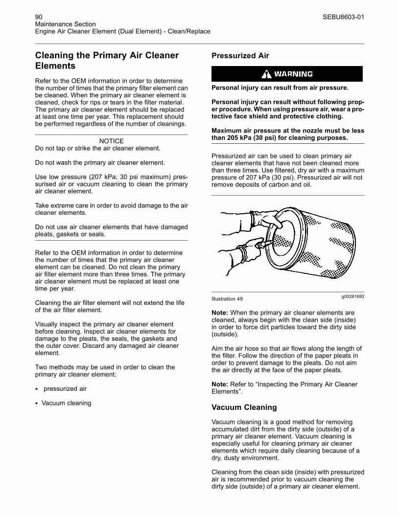
90 SEBU8603-01Maintenance SectionEngine Air Cleaner Element (Dual Element) - Clean/Replace
Cleaning the Primary Air CleanerElementsRefer to the OEM information in order to determinethe number of times that the primary filter element canbe cleaned. When the primary air cleaner element iscleaned, check for rips or tears in the filter material.The primary air cleaner element should be replacedat least one time per year. This replacement shouldbe performed regardless of the number of cleanings.
NOTICEDo not tap or strike the air cleaner element.
Do not wash the primary air cleaner element.
Use low pressure (207 kPa; 30 psi maximum) pres-surised air or vacuum cleaning to clean the primaryair cleaner element.
Take extreme care in order to avoid damage to the aircleaner elements.
Do not use air cleaner elements that have damagedpleats, gaskets or seals.
Refer to the OEM information in order to determinethe number of times that the primary air cleanerelement can be cleaned. Do not clean the primaryair filter element more than three times. The primaryair cleaner element must be replaced at least onetime per year.
Cleaning the air filter element will not extend the lifeof the air filter element.
Visually inspect the primary air cleaner elementbefore cleaning. Inspect air cleaner elements fordamage to the pleats, the seals, the gaskets andthe outer cover. Discard any damaged air cleanerelement.
Two methods may be used in order to clean theprimary air cleaner element:
• pressurized air
• Vacuum cleaning
Pressurized Air
Personal injury can result from air pressure.
Personal injury can result without following prop-er procedure.When using pressure air, wear a pro-tective face shield and protective clothing.
Maximum air pressure at the nozzle must be lessthan 205 kPa (30 psi) for cleaning purposes.
Pressurized air can be used to clean primary aircleaner elements that have not been cleaned morethan three times. Use filtered, dry air with a maximumpressure of 207 kPa (30 psi). Pressurized air will notremove deposits of carbon and oil.
g00281692Illustration 49
Note: When the primary air cleaner elements arecleaned, always begin with the clean side (inside)in order to force dirt particles toward the dirty side(outside).
Aim the air hose so that air flows along the length ofthe filter. Follow the direction of the paper pleats inorder to prevent damage to the pleats. Do not aimthe air directly at the face of the paper pleats.
Note: Refer to “Inspecting the Primary Air CleanerElements”.
Vacuum Cleaning
Vacuum cleaning is a good method for removingaccumulated dirt from the dirty side (outside) of aprimary air cleaner element. Vacuum cleaning isespecially useful for cleaning primary air cleanerelements which require daily cleaning because of adry, dusty environment.
Cleaning from the clean side (inside) with pressurizedair is recommended prior to vacuum cleaning thedirty side (outside) of a primary air cleaner element.
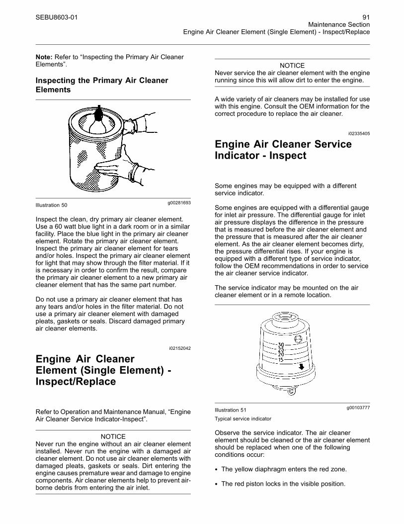
SEBU8603-01 91Maintenance Section
Engine Air Cleaner Element (Single Element) - Inspect/Replace
Note: Refer to “Inspecting the Primary Air CleanerElements”.
Inspecting the Primary Air CleanerElements
g00281693Illustration 50
Inspect the clean, dry primary air cleaner element.Use a 60 watt blue light in a dark room or in a similarfacility. Place the blue light in the primary air cleanerelement. Rotate the primary air cleaner element.Inspect the primary air cleaner element for tearsand/or holes. Inspect the primary air cleaner elementfor light that may show through the filter material. If itis necessary in order to confirm the result, comparethe primary air cleaner element to a new primary aircleaner element that has the same part number.
Do not use a primary air cleaner element that hasany tears and/or holes in the filter material. Do notuse a primary air cleaner element with damagedpleats, gaskets or seals. Discard damaged primaryair cleaner elements.
i02152042
Engine Air CleanerElement (Single Element) -Inspect/Replace
Refer to Operation and Maintenance Manual, “EngineAir Cleaner Service Indicator-Inspect”.
NOTICENever run the engine without an air cleaner elementinstalled. Never run the engine with a damaged aircleaner element. Do not use air cleaner elements withdamaged pleats, gaskets or seals. Dirt entering theengine causes premature wear and damage to enginecomponents. Air cleaner elements help to prevent air-borne debris from entering the air inlet.
NOTICENever service the air cleaner element with the enginerunning since this will allow dirt to enter the engine.
A wide variety of air cleaners may be installed for usewith this engine. Consult the OEM information for thecorrect procedure to replace the air cleaner.
i02335405
Engine Air Cleaner ServiceIndicator - Inspect
Some engines may be equipped with a differentservice indicator.
Some engines are equipped with a differential gaugefor inlet air pressure. The differential gauge for inletair pressure displays the difference in the pressurethat is measured before the air cleaner element andthe pressure that is measured after the air cleanerelement. As the air cleaner element becomes dirty,the pressure differential rises. If your engine isequipped with a different type of service indicator,follow the OEM recommendations in order to servicethe air cleaner service indicator.
The service indicator may be mounted on the aircleaner element or in a remote location.
g00103777Illustration 51
Typical service indicator
Observe the service indicator. The air cleanerelement should be cleaned or the air cleaner elementshould be replaced when one of the followingconditions occur:
• The yellow diaphragm enters the red zone.
• The red piston locks in the visible position.
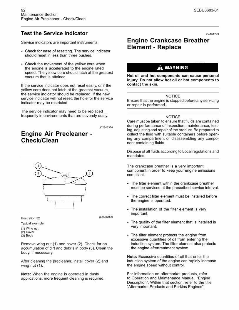
92 SEBU8603-01Maintenance SectionEngine Air Precleaner - Check/Clean
Test the Service IndicatorService indicators are important instruments.
• Check for ease of resetting. The service indicatorshould reset in less than three pushes.
• Check the movement of the yellow core whenthe engine is accelerated to the engine ratedspeed. The yellow core should latch at the greatestvacuum that is attained.
If the service indicator does not reset easily, or if theyellow core does not latch at the greatest vacuum,the service indicator should be replaced. If the newservice indicator will not reset, the hole for the serviceindicator may be restricted.
The service indicator may need to be replacedfrequently in environments that are severely dusty.
i02343354
Engine Air Precleaner -Check/Clean
g00287039Illustration 52Typical example
(1) Wing nut(2) Cover(3) Body
Remove wing nut (1) and cover (2). Check for anaccumulation of dirt and debris in body (3). Clean thebody, if necessary.
After cleaning the precleaner, install cover (2) andwing nut (1).
Note: When the engine is operated in dustyapplications, more frequent cleaning is required.
i04151729
Engine Crankcase BreatherElement - Replace
Hot oil and hot components can cause personalinjury. Do not allow hot oil or hot components tocontact the skin.
NOTICEEnsure that the engine is stopped before any servicingor repair is performed.
NOTICECare must be taken to ensure that fluids are containedduring performance of inspection, maintenance, test-ing, adjusting and repair of the product. Be prepared tocollect the fluid with suitable containers before open-ing any compartment or disassembling any compo-nent containing fluids.
Dispose of all fluids according to Local regulations andmandates.
The crankcase breather is a very importantcomponent in order to keep your engine emissionscompliant.
• The filter element within the crankcase breathermust be serviced at the prescribed service interval.
• The correct filter element must be installed beforethe engine is operated.
• The installation of the filter element is veryimportant.
• The quality of the filter element that is installed isvery important.
• The filter element protects the engine fromexcessive quantities of oil from entering theinduction system. The filter element also protectsthe engine aftertreatment system.
Note: Excessive quantities of oil that enter theinduction system of the engine can rapidly increasethe engine speed without control.
For information on aftermarket products, referto Operation and Maintenance Manual, “EngineDescription”. Within that section, refer to the title“Aftermarket Products and Perkins Engines”.
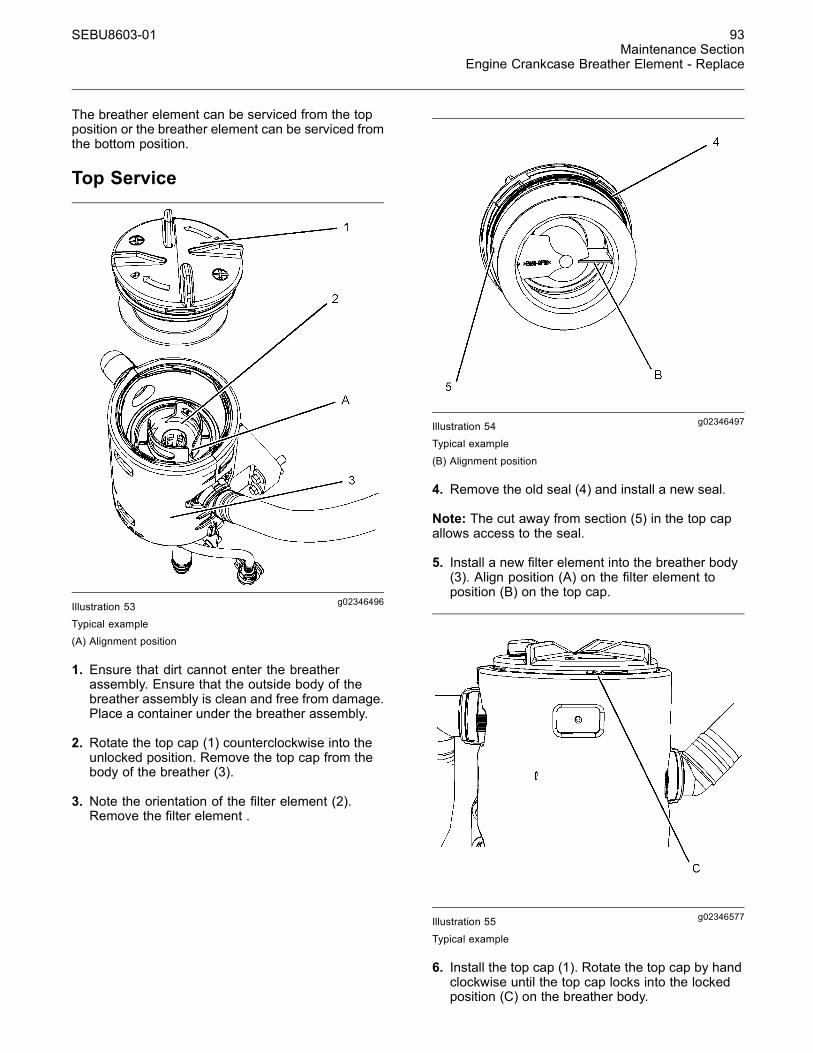
SEBU8603-01 93Maintenance Section
Engine Crankcase Breather Element - Replace
The breather element can be serviced from the topposition or the breather element can be serviced fromthe bottom position.
Top Service
g02346496Illustration 53Typical example(A) Alignment position
1. Ensure that dirt cannot enter the breatherassembly. Ensure that the outside body of thebreather assembly is clean and free from damage.Place a container under the breather assembly.
2. Rotate the top cap (1) counterclockwise into theunlocked position. Remove the top cap from thebody of the breather (3).
3. Note the orientation of the filter element (2).Remove the filter element .
g02346497Illustration 54Typical example
(B) Alignment position
4. Remove the old seal (4) and install a new seal.
Note: The cut away from section (5) in the top capallows access to the seal.
5. Install a new filter element into the breather body(3). Align position (A) on the filter element toposition (B) on the top cap.
g02346577Illustration 55
Typical example
6. Install the top cap (1). Rotate the top cap by handclockwise until the top cap locks into the lockedposition (C) on the breather body.
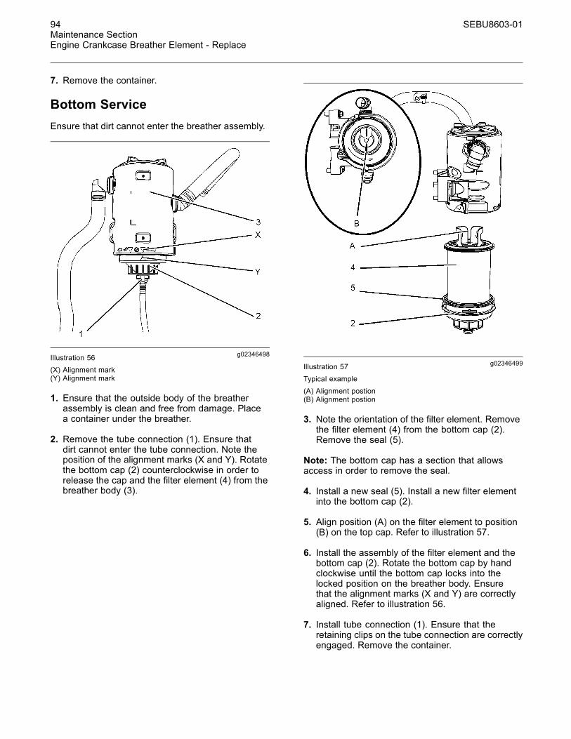
94 SEBU8603-01Maintenance SectionEngine Crankcase Breather Element - Replace
7. Remove the container.
Bottom ServiceEnsure that dirt cannot enter the breather assembly.
g02346498Illustration 56(X) Alignment mark(Y) Alignment mark
1. Ensure that the outside body of the breatherassembly is clean and free from damage. Placea container under the breather.
2. Remove the tube connection (1). Ensure thatdirt cannot enter the tube connection. Note theposition of the alignment marks (X and Y). Rotatethe bottom cap (2) counterclockwise in order torelease the cap and the filter element (4) from thebreather body (3).
g02346499Illustration 57
Typical example
(A) Alignment postion(B) Alignment postion
3. Note the orientation of the filter element. Removethe filter element (4) from the bottom cap (2).Remove the seal (5).
Note: The bottom cap has a section that allowsaccess in order to remove the seal.
4. Install a new seal (5). Install a new filter elementinto the bottom cap (2).
5. Align position (A) on the filter element to position(B) on the top cap. Refer to illustration 57.
6. Install the assembly of the filter element and thebottom cap (2). Rotate the bottom cap by handclockwise until the bottom cap locks into thelocked position on the breather body. Ensurethat the alignment marks (X and Y) are correctlyaligned. Refer to illustration 56.
7. Install tube connection (1). Ensure that theretaining clips on the tube connection are correctlyengaged. Remove the container.
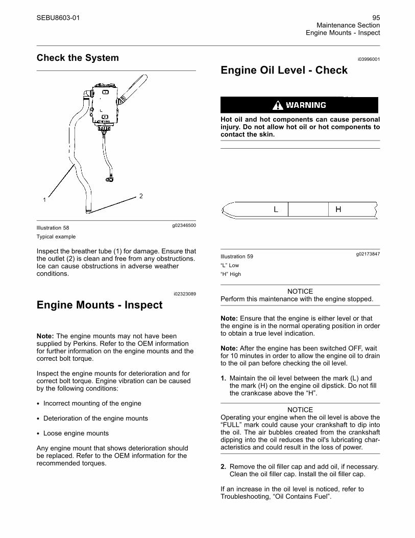
SEBU8603-01 95Maintenance Section
Engine Mounts - Inspect
Check the System
g02346500Illustration 58Typical example
Inspect the breather tube (1) for damage. Ensure thatthe outlet (2) is clean and free from any obstructions.Ice can cause obstructions in adverse weatherconditions.
i02323089
Engine Mounts - Inspect
Note: The engine mounts may not have beensupplied by Perkins. Refer to the OEM informationfor further information on the engine mounts and thecorrect bolt torque.
Inspect the engine mounts for deterioration and forcorrect bolt torque. Engine vibration can be causedby the following conditions:
• Incorrect mounting of the engine
• Deterioration of the engine mounts
• Loose engine mounts
Any engine mount that shows deterioration shouldbe replaced. Refer to the OEM information for therecommended torques.
i03996001
Engine Oil Level - Check
Hot oil and hot components can cause personalinjury. Do not allow hot oil or hot components tocontact the skin.
g02173847Illustration 59
“L” Low“H” High
NOTICEPerform this maintenance with the engine stopped.
Note: Ensure that the engine is either level or thatthe engine is in the normal operating position in orderto obtain a true level indication.
Note: After the engine has been switched OFF, waitfor 10 minutes in order to allow the engine oil to drainto the oil pan before checking the oil level.
1. Maintain the oil level between the mark (L) andthe mark (H) on the engine oil dipstick. Do not fillthe crankcase above the “H”.
NOTICEOperating your engine when the oil level is above the“FULL” mark could cause your crankshaft to dip intothe oil. The air bubbles created from the crankshaftdipping into the oil reduces the oil's lubricating char-acteristics and could result in the loss of power.
2. Remove the oil filler cap and add oil, if necessary.Clean the oil filler cap. Install the oil filler cap.
If an increase in the oil level is noticed, refer toTroubleshooting, “Oil Contains Fuel”.
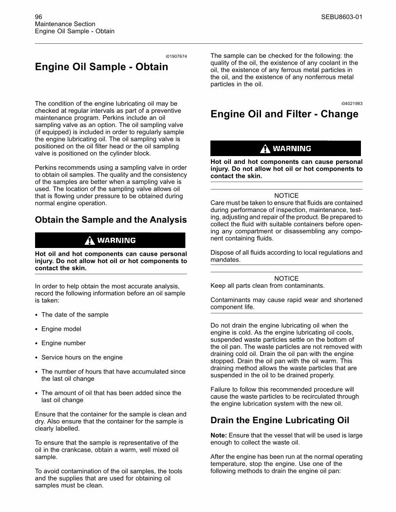
96 SEBU8603-01Maintenance SectionEngine Oil Sample - Obtain
i01907674
Engine Oil Sample - Obtain
The condition of the engine lubricating oil may bechecked at regular intervals as part of a preventivemaintenance program. Perkins include an oilsampling valve as an option. The oil sampling valve(if equipped) is included in order to regularly samplethe engine lubricating oil. The oil sampling valve ispositioned on the oil filter head or the oil samplingvalve is positioned on the cylinder block.
Perkins recommends using a sampling valve in orderto obtain oil samples. The quality and the consistencyof the samples are better when a sampling valve isused. The location of the sampling valve allows oilthat is flowing under pressure to be obtained duringnormal engine operation.
Obtain the Sample and the Analysis
Hot oil and hot components can cause personalinjury. Do not allow hot oil or hot components tocontact the skin.
In order to help obtain the most accurate analysis,record the following information before an oil sampleis taken:
• The date of the sample
• Engine model
• Engine number
• Service hours on the engine
• The number of hours that have accumulated sincethe last oil change
• The amount of oil that has been added since thelast oil change
Ensure that the container for the sample is clean anddry. Also ensure that the container for the sample isclearly labelled.
To ensure that the sample is representative of theoil in the crankcase, obtain a warm, well mixed oilsample.
To avoid contamination of the oil samples, the toolsand the supplies that are used for obtaining oilsamples must be clean.
The sample can be checked for the following: thequality of the oil, the existence of any coolant in theoil, the existence of any ferrous metal particles inthe oil, and the existence of any nonferrous metalparticles in the oil.
i04021983
Engine Oil and Filter - Change
Hot oil and hot components can cause personalinjury. Do not allow hot oil or hot components tocontact the skin.
NOTICECare must be taken to ensure that fluids are containedduring performance of inspection, maintenance, test-ing, adjusting and repair of the product. Be prepared tocollect the fluid with suitable containers before open-ing any compartment or disassembling any compo-nent containing fluids.
Dispose of all fluids according to local regulations andmandates.
NOTICEKeep all parts clean from contaminants.
Contaminants may cause rapid wear and shortenedcomponent life.
Do not drain the engine lubricating oil when theengine is cold. As the engine lubricating oil cools,suspended waste particles settle on the bottom ofthe oil pan. The waste particles are not removed withdraining cold oil. Drain the oil pan with the enginestopped. Drain the oil pan with the oil warm. Thisdraining method allows the waste particles that aresuspended in the oil to be drained properly.
Failure to follow this recommended procedure willcause the waste particles to be recirculated throughthe engine lubrication system with the new oil.
Drain the Engine Lubricating OilNote: Ensure that the vessel that will be used is largeenough to collect the waste oil.
After the engine has been run at the normal operatingtemperature, stop the engine. Use one of thefollowing methods to drain the engine oil pan:

SEBU8603-01 97Maintenance Section
Engine Oil and Filter - Change
g02178063Illustration 60Typical example
• If the engine is equipped with a drain valve, turn thedrain valve knob counterclockwise in order to drainthe oil. After the oil has drained, turn the drain valveknob clockwise in order to close the drain valve.
• If the engine is not equipped with a drain valve,remove the oil drain plug (1) in order to allow the oilto drain. If the engine is equipped with a shallow oilpan, remove the bottom oil drain plugs from bothends of the oil pan.
After the oil has drained, the oil drain plugs should becleaned and installed. If necessary, replace the Oring seal. Tighten the drain plug to 34 N·m (25 lb ft).
Replace the Oil Filter
NOTICEPerkins oil filters are manufactured to Perkins speci-fications. Use of an oil filter that is not recommendedby Perkins could result in severe damage to the en-gine bearings, crankshaft, etc., as a result of the largerwaste particles from unfiltered oil entering the enginelubricating system. Only use oil filters recommendedby Perkins.
1. Place a suitable container below the oil filterassembly. Remove the oil filter with a suitable tool.
2. Clean sealing surface of the oil filter base (2).
3. Apply clean engine oil to O ring seal (3) for thenew oil filter.
NOTICEDo not fill the oil filters with oil before installing them.This oil would not be filtered and could be contaminat-ed. Contaminated oil can cause accelerated wear toengine components.
4. Install the new oil filter. Spin on the oil filter untilthe O ring contacts the sealing surface (2). Thenrotate the oil filter ¾ of a full turn.
Fill the Oil Pan1. Remove the oil filler cap. Refer to thisOperation and Maintenance Manual, “FluidRecommendations” for more information onsuitable oils. Fill the oil pan with the correctamount of new engine lubricating oil. Referto this Operation and Maintenance Manual,“Refill Capacities” for more information on refillcapacities.
NOTICEIf equipped with an auxiliary oil filter system or a re-mote filter system, follow the OEM or the filter manu-factures recommendations. Under filling or over fillingthe crankcase with oil can cause engine damage.
2. Start the engine and run the engine at “LOWIDLE” for 2 minutes. Perform this procedure inorder to ensure that the lubrication system hasoil and that the oil filters are filled. Inspect the oilfilter for oil leaks.
3. Stop the engine and allow the oil to drain back tothe oil pan for a minimum of 10 minutes.
g02173847Illustration 61
4. Remove the engine oil level gauge in order tocheck the oil level. Maintain the oil level betweenthe “L” and “H” marks on the engine oil levelgauge. Do not fill the crankcase above the “H”mark.
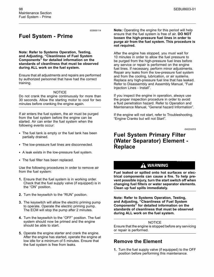
98 SEBU8603-01Maintenance SectionFuel System - Prime
i03906114
Fuel System - Prime
Note: Refer to Systems Operation, Testing,and Adjusting, “Cleanliness of Fuel SystemComponents” for detailed information on thestandards of cleanliness that must be observedduring ALL work on the fuel system.
Ensure that all adjustments and repairs are performedby authorized personnel that have had the correcttraining.
NOTICEDo not crank the engine continuously for more than30 seconds. Allow the starting motor to cool for twominutes before cranking the engine again.
If air enters the fuel system, the air must be purgedfrom the fuel system before the engine can bestarted. Air can enter the fuel system when thefollowing events occur:
• The fuel tank is empty or the fuel tank has beenpartially drained.
• The low-pressure fuel lines are disconnected.
• A leak exists in the low-pressure fuel system.
• The fuel filter has been replaced.
Use the following procedures in order to remove airfrom the fuel system:
1. Ensure that the fuel system is in working order.Check that the fuel supply valve (if equipped) is inthe “ON” position.
2. Turn the keyswitch to the “RUN” position.
3. The keyswitch will allow the electric priming pumpto operate. Operate the electric priming pump.The ECM will stop the pump after 2 minutes.
4. Turn the keyswitch to the “OFF” position. The fuelsystem should now be primed and the engineshould be able to start.
5. Operate the engine starter and crank the engine.After the engine has started, operate the engine atlow idle for a minimum of 5 minutes. Ensure thatthe fuel system is free from leaks.
Note: Operating the engine for this period will helpensure that the fuel system is free of air. DO NOTloosen the high-pressure fuel lines in order topurge air from the fuel system. This procedure isnot required.
After the engine has stopped, you must wait for10 minutes in order to allow the fuel pressure tobe purged from the high-pressure fuel lines beforeany service or repair is performed on the enginefuel lines. If necessary, perform minor adjustments.Repair any leaks from the low-pressure fuel systemand from the cooling, lubrication, or air systems.Replace any high-pressure fuel line that has leaked.Refer to Disassembly and Assembly Manual, “FuelInjection Lines - Install”.
If you inspect the engine in operation, always usethe proper inspection procedure in order to avoida fluid penetration hazard. Refer to Operation andMaintenance Manual, “General hazard Information”.
If the engine will not start, refer to Troubleshooting,“Engine Cranks but will not Start”.
i04224203
Fuel System Primary Filter(Water Separator) Element -Replace
Fuel leaked or spilled onto hot surfaces or elec-trical components can cause a fire. To help pre-vent possible injury, turn the start switch off whenchanging fuel filters or water separator elements.Clean up fuel spills immediately.
Note: Refer to Systems Operation, Testing,and Adjusting, “Cleanliness of Fuel SystemComponents” for detailed information on thestandards of cleanliness that must be observedduring ALL work on the fuel system.
NOTICEEnsure that the engine is stopped before any servicingor repair is performed.
Remove the Element1. Turn the fuel supply valve (if equipped) to the OFFposition before performing this maintenance.
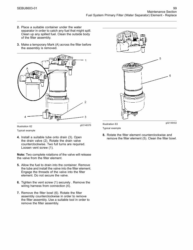
SEBU8603-01 99Maintenance Section
Fuel System Primary Filter (Water Separator) Element - Replace
2. Place a suitable container under the waterseparator in order to catch any fuel that might spill.Clean up any spilled fuel. Clean the outside bodyof the filter assembly.
3. Make a temporary Mark (A) across the filter beforethe assembly is removed.
g02148376Illustration 62
Typical example
4. Install a suitable tube onto drain (3). Openthe drain valve (2). Rotate the drain valvecounterclockwise. Two full turns are required.Loosen vent screw (1).
Note: Two complete rotations of the valve will releasethe valve from the filter element.
5. Allow the fuel to drain into the container. Removethe tube and install the valve into the filter element.Engage the threads of the valve into the filterelement. Do not secure the valve.
6. Tighten the vent screw (1) securely . Remove thewiring harness from connection (4).
7. Remove the filter bowl (6). Rotate the filterassembly counterclockwise in order to removethe filter assembly. Use a suitable tool in order toremove the filter assembly.
g02148402Illustration 63
Typical example
8. Rotate the filter element counterclockwise andremove the filter element (5). Clean the filter bowl.
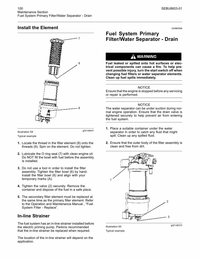
100 SEBU8603-01Maintenance SectionFuel System Primary Filter/Water Separator - Drain
Install the Element
g02148441Illustration 64Typical example
1. Locate the thread in the filter element (8) onto thethreads (9). Spin on the element. Do not tighten.
2. Lubricate the O ring seal (7) with clean engine oil.Do NOT fill the bowl with fuel before the assemblyis installed.
3. Do not use a tool in order to install the filterassembly. Tighten the filter bowl (6) by hand.Install the filter bowl (6) and align with yourtemporary marks (A).
4. Tighten the valve (2) securely. Remove thecontainer and dispose of the fuel in a safe place.
5. The secondary filter element must be replaced atthe same time as the primary filter element. Referto the Operation and Maintenance Manual , “FuelSystem Filter - Replace”.
In-line StrainerThe fuel system has an in-line strainer installed beforethe electric priming pump. Perkins recommendedthat the in-line strainer be replaced when required.
The location of the in-line strainer will depend on theapplication.
i03980098
Fuel System PrimaryFilter/Water Separator - Drain
Fuel leaked or spilled onto hot surfaces or elec-trical components can cause a fire. To help pre-vent possible injury, turn the start switch off whenchanging fuel filters or water separator elements.Clean up fuel spills immediately.
NOTICEEnsure that the engine is stopped before any servicingor repair is performed.
NOTICEThe water separator can be under suction during nor-mal engine operation. Ensure that the drain valve istightened securely to help prevent air from enteringthe fuel system.
1. Place a suitable container under the waterseparator in order to catch any fluid that mightspill. Clean up any spilled fluid.
2. Ensure that the outer body of the filter assembly isclean and free from dirt.
g02148370Illustration 65Typical example
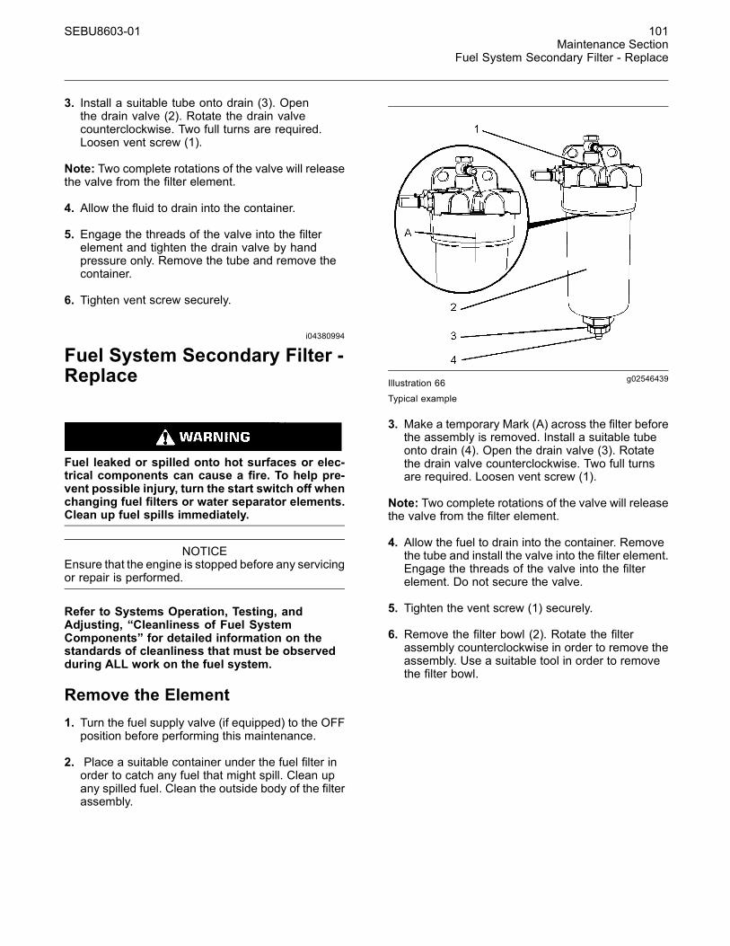
SEBU8603-01 101Maintenance Section
Fuel System Secondary Filter - Replace
3. Install a suitable tube onto drain (3). Openthe drain valve (2). Rotate the drain valvecounterclockwise. Two full turns are required.Loosen vent screw (1).
Note: Two complete rotations of the valve will releasethe valve from the filter element.
4. Allow the fluid to drain into the container.
5. Engage the threads of the valve into the filterelement and tighten the drain valve by handpressure only. Remove the tube and remove thecontainer.
6. Tighten vent screw securely.
i04380994
Fuel System Secondary Filter -Replace
Fuel leaked or spilled onto hot surfaces or elec-trical components can cause a fire. To help pre-vent possible injury, turn the start switch off whenchanging fuel filters or water separator elements.Clean up fuel spills immediately.
NOTICEEnsure that the engine is stopped before any servicingor repair is performed.
Refer to Systems Operation, Testing, andAdjusting, “Cleanliness of Fuel SystemComponents” for detailed information on thestandards of cleanliness that must be observedduring ALL work on the fuel system.
Remove the Element1. Turn the fuel supply valve (if equipped) to the OFFposition before performing this maintenance.
2. Place a suitable container under the fuel filter inorder to catch any fuel that might spill. Clean upany spilled fuel. Clean the outside body of the filterassembly.
g02546439Illustration 66Typical example
3. Make a temporary Mark (A) across the filter beforethe assembly is removed. Install a suitable tubeonto drain (4). Open the drain valve (3). Rotatethe drain valve counterclockwise. Two full turnsare required. Loosen vent screw (1).
Note: Two complete rotations of the valve will releasethe valve from the filter element.
4. Allow the fuel to drain into the container. Removethe tube and install the valve into the filter element.Engage the threads of the valve into the filterelement. Do not secure the valve.
5. Tighten the vent screw (1) securely.
6. Remove the filter bowl (2). Rotate the filterassembly counterclockwise in order to remove theassembly. Use a suitable tool in order to removethe filter bowl.
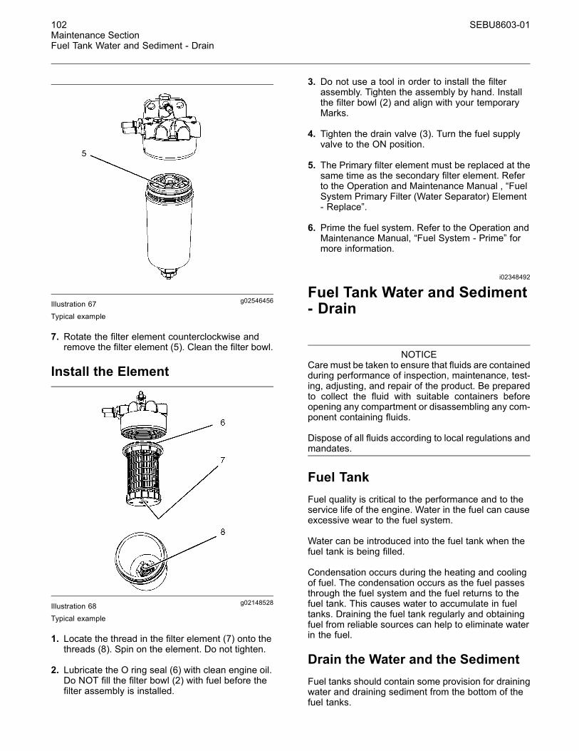
102 SEBU8603-01Maintenance SectionFuel Tank Water and Sediment - Drain
g02546456Illustration 67Typical example
7. Rotate the filter element counterclockwise andremove the filter element (5). Clean the filter bowl.
Install the Element
g02148528Illustration 68Typical example
1. Locate the thread in the filter element (7) onto thethreads (8). Spin on the element. Do not tighten.
2. Lubricate the O ring seal (6) with clean engine oil.Do NOT fill the filter bowl (2) with fuel before thefilter assembly is installed.
3. Do not use a tool in order to install the filterassembly. Tighten the assembly by hand. Installthe filter bowl (2) and align with your temporaryMarks.
4. Tighten the drain valve (3). Turn the fuel supplyvalve to the ON position.
5. The Primary filter element must be replaced at thesame time as the secondary filter element. Referto the Operation and Maintenance Manual , “FuelSystem Primary Filter (Water Separator) Element- Replace”.
6. Prime the fuel system. Refer to the Operation andMaintenance Manual, “Fuel System - Prime” formore information.
i02348492
Fuel Tank Water and Sediment- Drain
NOTICECare must be taken to ensure that fluids are containedduring performance of inspection, maintenance, test-ing, adjusting, and repair of the product. Be preparedto collect the fluid with suitable containers beforeopening any compartment or disassembling any com-ponent containing fluids.
Dispose of all fluids according to local regulations andmandates.
Fuel TankFuel quality is critical to the performance and to theservice life of the engine. Water in the fuel can causeexcessive wear to the fuel system.
Water can be introduced into the fuel tank when thefuel tank is being filled.
Condensation occurs during the heating and coolingof fuel. The condensation occurs as the fuel passesthrough the fuel system and the fuel returns to thefuel tank. This causes water to accumulate in fueltanks. Draining the fuel tank regularly and obtainingfuel from reliable sources can help to eliminate waterin the fuel.
Drain the Water and the SedimentFuel tanks should contain some provision for drainingwater and draining sediment from the bottom of thefuel tanks.
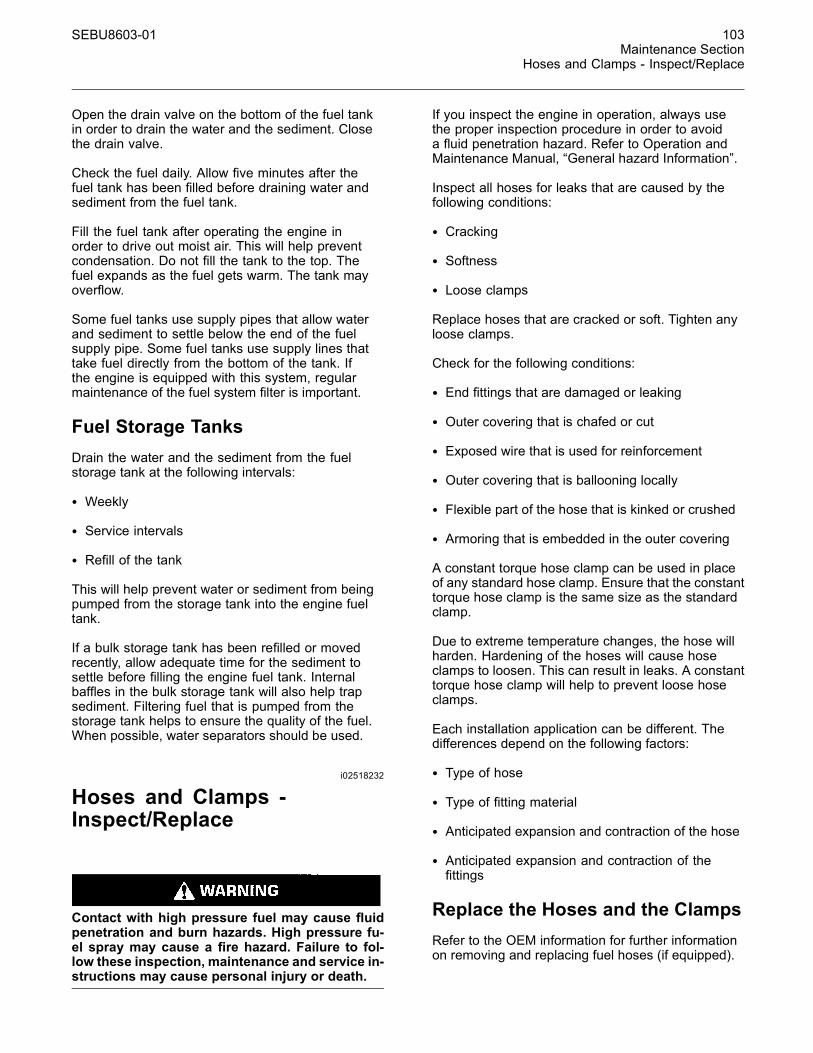
SEBU8603-01 103Maintenance Section
Hoses and Clamps - Inspect/Replace
Open the drain valve on the bottom of the fuel tankin order to drain the water and the sediment. Closethe drain valve.
Check the fuel daily. Allow five minutes after thefuel tank has been filled before draining water andsediment from the fuel tank.
Fill the fuel tank after operating the engine inorder to drive out moist air. This will help preventcondensation. Do not fill the tank to the top. Thefuel expands as the fuel gets warm. The tank mayoverflow.
Some fuel tanks use supply pipes that allow waterand sediment to settle below the end of the fuelsupply pipe. Some fuel tanks use supply lines thattake fuel directly from the bottom of the tank. Ifthe engine is equipped with this system, regularmaintenance of the fuel system filter is important.
Fuel Storage TanksDrain the water and the sediment from the fuelstorage tank at the following intervals:
• Weekly
• Service intervals
• Refill of the tank
This will help prevent water or sediment from beingpumped from the storage tank into the engine fueltank.
If a bulk storage tank has been refilled or movedrecently, allow adequate time for the sediment tosettle before filling the engine fuel tank. Internalbaffles in the bulk storage tank will also help trapsediment. Filtering fuel that is pumped from thestorage tank helps to ensure the quality of the fuel.When possible, water separators should be used.
i02518232
Hoses and Clamps -Inspect/Replace
Contact with high pressure fuel may cause fluidpenetration and burn hazards. High pressure fu-el spray may cause a fire hazard. Failure to fol-low these inspection, maintenance and service in-structions may cause personal injury or death.
If you inspect the engine in operation, always usethe proper inspection procedure in order to avoida fluid penetration hazard. Refer to Operation andMaintenance Manual, “General hazard Information”.
Inspect all hoses for leaks that are caused by thefollowing conditions:
• Cracking
• Softness
• Loose clamps
Replace hoses that are cracked or soft. Tighten anyloose clamps.
Check for the following conditions:
• End fittings that are damaged or leaking
• Outer covering that is chafed or cut
• Exposed wire that is used for reinforcement
• Outer covering that is ballooning locally
• Flexible part of the hose that is kinked or crushed
• Armoring that is embedded in the outer covering
A constant torque hose clamp can be used in placeof any standard hose clamp. Ensure that the constanttorque hose clamp is the same size as the standardclamp.
Due to extreme temperature changes, the hose willharden. Hardening of the hoses will cause hoseclamps to loosen. This can result in leaks. A constanttorque hose clamp will help to prevent loose hoseclamps.
Each installation application can be different. Thedifferences depend on the following factors:
• Type of hose
• Type of fitting material
• Anticipated expansion and contraction of the hose
• Anticipated expansion and contraction of thefittings
Replace the Hoses and the ClampsRefer to the OEM information for further informationon removing and replacing fuel hoses (if equipped).
104 SEBU8603-01Maintenance SectionRadiator - Clean
The following text describes a typical methodof replacing coolant hoses. Refer to the OEMinformation for further information on the coolantsystem and the hoses for the coolant system.
Pressurized System: Hot coolant can cause seri-ous burns. To open the cooling system filler cap,stop the engine and wait until the cooling systemcomponents are cool. Loosen the cooling systempressure cap slowly in order to relieve the pres-sure.
1. Stop the engine. Allow the engine to cool.
2. Loosen the cooling system filler cap slowly inorder to relieve any pressure. Remove the coolingsystem filler cap.
Note: Drain the coolant into a suitable, cleancontainer. The coolant can be reused.
3. Drain the coolant from the cooling system to alevel that is below the hose that is being replaced.
4. Remove the hose clamps.
5. Disconnect the old hose.
6. Replace the old hose with a new hose.
7. Install the hose clamps with a torque wrench.
Note: For the correct coolant, see this Operation andMaintenance Manual, “Fluid Recommendations”.
8. Refill the cooling system. Refer to the OEMinformation for further information on refilling thecooling system.
9. Clean the cooling system filler cap. Inspect thecooling system filler cap's seals. Replace thecooling system filler cap if the seals are damaged.Install the cooling system filler cap.
10.Start the engine. Inspect the cooling system forleaks.
i04245214
Radiator - Clean
The radiator is not usually supplied by Perkins. Thefollowing text describes a typical cleaning procedurefor the radiator. Refer to the OEM information forfurther information on cleaning the radiator.
Note: Some application will require a fuel coolerto be installed. The fuel cooler is a type of radiatorthat uses air to cool the fuel and the fuel cooler willrequire cleaning.
Note: Adjust the frequency of cleaning according tothe effects of the operating environment.
Inspect the radiator for these items: Damaged fins,corrosion, dirt, grease, insects, leaves, oil, and otherdebris. Clean the radiator, if necessary.
Personal injury can result from air pressure.
Personal injury can result without following prop-er procedure.When using pressure air, wear a pro-tective face shield and protective clothing.
Maximum air pressure at the nozzle must be lessthan 205 kPa (30 psi) for cleaning purposes.
Pressurized air is the preferred method for removingloose debris. Direct the air in the opposite directionto the fans air flow. Hold the nozzle approximately6 mm (0.25 inch) away from the radiator fins. Slowlymove the air nozzle in a direction that is parallel withthe radiator tube assembly. The pressurized air willremove debris that is between the tubes.
Pressurized water may also be used for cleaning.The maximum water pressure for cleaning purposesmust be less than 275 kPa (40 psi). Use pressurizedwater in order to soften mud. Clean the core fromboth sides.
Use a degreaser and steam for removal of oil andgrease. Clean both sides of the core. Wash the corewith detergent and hot water. Thoroughly rinse thecore with clean water.
If the radiator is blocked internally, refer to the OEMManual for information regarding flushing the coolingsystem.
After cleaning the radiator, start the engine. Allowthe engine to operate at low idle speed for 3 to 5minutes. Accelerate the engine to high idle. The highidle speed will help in the removal of debris and thedrying of the core. Slowly reduce the engine speedto low idle and then stop the engine. Use a lightbulb behind the core in order to inspect the core forcleanliness. Repeat the cleaning, if necessary.
Inspect the fins for damage. Bent fins may be openedwith a “comb”. Inspect these items for good condition:Welds, mounting brackets, air lines, connections,clamps, and seals. Make repairs, if necessary.
SEBU8603-01 105Maintenance Section
Severe Service Application - Check
i02335775
Severe Service Application -Check
Severe service is the application of an engine thatexceeds the current published standards for thatengine. Perkins maintains standards for the followingengine parameters:
• Performance such as power range, speed range,and fuel consumption
• Fuel quality
• Operational Altitude
• Maintenance intervals
• Oil selection and maintenance
• Coolant type and maintenance
• Environmental qualities
• Installation
• The temperature of the fluid in the engine
Refer to the standards for the engine or consult yourPerkins dealer or your Perkins distributor in order todetermine if the engine is operating within the definedparameters.
Severe service operation can accelerate componentwear. Engines that operate under severe conditionsmay need more frequent maintenance intervals inorder to ensure maximum reliability and retention offull service life.
Due to individual applications, it is not possibleto identify all of the factors which can contributeto severe service operation. Consult your Perkinsdealer or your Perkins distributor for the uniquemaintenance that is necessary for the engine.
The operating environment, incorrect operatingprocedures and incorrect maintenance procedurescan be factors which contribute to a severe serviceapplication.
Environmental FactorsAmbient temperatures – The engine may beexposed to extended operation in extremelycold environments or hot environments. Valvecomponents can be damaged by carbon buildup ifthe engine is frequently started and stopped in verycold temperatures. Extremely hot intake air reducesengine performance.
Quality of the air – The engine may be exposedto extended operation in an environment that isdirty or dusty, unless the equipment is cleanedregularly. Mud, dirt and dust can encase components.Maintenance can be very difficult. The buildup cancontain corrosive chemicals.
Buildup – Compounds, elements, corrosivechemicals and salt can damage some components.
Altitude – Problems can arise when the engine isoperated at altitudes that are higher than the intendedsettings for that application. Necessary adjustmentsshould be made.
Incorrect Operating Procedures• Extended operation at low idle
• Frequent hot shutdowns
• Operating at excessive loads
• Operating at excessive speeds
• Operating outside the intended application
Incorrect Maintenance Procedures• Extending the maintenance intervals
• Failure to use recommended fuel, lubricants andcoolant/antifreeze
i02177969
Starting Motor - Inspect
Perkins recommends a scheduled inspection of thestarting motor. If the starting motor fails, the enginemay not start in an emergency situation.
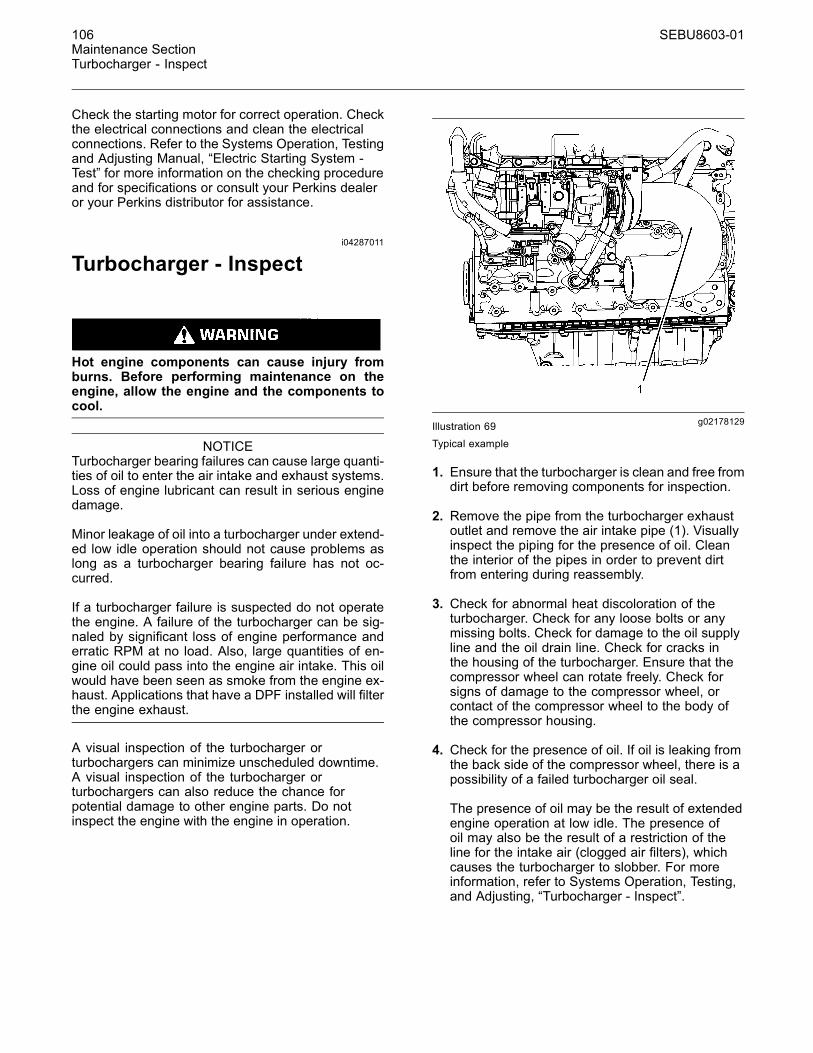
106 SEBU8603-01Maintenance SectionTurbocharger - Inspect
Check the starting motor for correct operation. Checkthe electrical connections and clean the electricalconnections. Refer to the Systems Operation, Testingand Adjusting Manual, “Electric Starting System -Test” for more information on the checking procedureand for specifications or consult your Perkins dealeror your Perkins distributor for assistance.
i04287011
Turbocharger - Inspect
Hot engine components can cause injury fromburns. Before performing maintenance on theengine, allow the engine and the components tocool.
NOTICETurbocharger bearing failures can cause large quanti-ties of oil to enter the air intake and exhaust systems.Loss of engine lubricant can result in serious enginedamage.
Minor leakage of oil into a turbocharger under extend-ed low idle operation should not cause problems aslong as a turbocharger bearing failure has not oc-curred.
If a turbocharger failure is suspected do not operatethe engine. A failure of the turbocharger can be sig-naled by significant loss of engine performance anderratic RPM at no load. Also, large quantities of en-gine oil could pass into the engine air intake. This oilwould have been seen as smoke from the engine ex-haust. Applications that have a DPF installed will filterthe engine exhaust.
A visual inspection of the turbocharger orturbochargers can minimize unscheduled downtime.A visual inspection of the turbocharger orturbochargers can also reduce the chance forpotential damage to other engine parts. Do notinspect the engine with the engine in operation.
g02178129Illustration 69Typical example
1. Ensure that the turbocharger is clean and free fromdirt before removing components for inspection.
2. Remove the pipe from the turbocharger exhaustoutlet and remove the air intake pipe (1). Visuallyinspect the piping for the presence of oil. Cleanthe interior of the pipes in order to prevent dirtfrom entering during reassembly.
3. Check for abnormal heat discoloration of theturbocharger. Check for any loose bolts or anymissing bolts. Check for damage to the oil supplyline and the oil drain line. Check for cracks inthe housing of the turbocharger. Ensure that thecompressor wheel can rotate freely. Check forsigns of damage to the compressor wheel, orcontact of the compressor wheel to the body ofthe compressor housing.
4. Check for the presence of oil. If oil is leaking fromthe back side of the compressor wheel, there is apossibility of a failed turbocharger oil seal.
The presence of oil may be the result of extendedengine operation at low idle. The presence ofoil may also be the result of a restriction of theline for the intake air (clogged air filters), whichcauses the turbocharger to slobber. For moreinformation, refer to Systems Operation, Testing,and Adjusting, “Turbocharger - Inspect”.
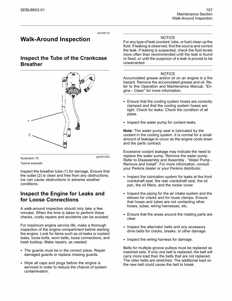
SEBU8603-01 107Maintenance Section
Walk-Around Inspection
i04156712
Walk-Around Inspection
Inspect the Tube of the CrankcaseBreather
g02351425Illustration 70Typical example
Inspect the breather tube (1) for damage. Ensure thatthe outlet (2) is clean and free from any obstructions.Ice can cause obstructions in adverse weatherconditions.
Inspect the Engine for Leaks andfor Loose ConnectionsA walk-around inspection should only take a fewminutes. When the time is taken to perform thesechecks, costly repairs and accidents can be avoided.
For maximum engine service life, make a thoroughinspection of the engine compartment before startingthe engine. Look for items such as oil leaks or coolantleaks, loose bolts, worn belts, loose connections, andtrash buildup. Make repairs, as needed:
• The guards must be in the correct place. Repairdamaged guards or replace missing guards.
• Wipe all caps and plugs before the engine isserviced in order to reduce the chance of systemcontamination.
NOTICEFor any type of leak (coolant, lube, or fuel) clean up thefluid. If leaking is observed, find the source and correctthe leak. If leaking is suspected, check the fluid levelsmore often than recommended until the leak is foundor fixed, or until the suspicion of a leak is proved to beunwarranted.
NOTICEAccumulated grease and/or oil on an engine is a firehazard. Remove the accumulated grease and oil. Re-fer to this Operation and Maintenance Manual, “En-gine - Clean” for more information.
• Ensure that the cooling system hoses are correctlyclamped and that the cooling system hoses aretight. Check for leaks. Check the condition of allpipes.
• Inspect the water pump for coolant leaks.
Note: The water pump seal is lubricated by thecoolant in the cooling system. It is normal for a smallamount of leakage to occur as the engine cools downand the parts contract.
Excessive coolant leakage may indicate the need toreplace the water pump. Remove the water pump.Refer to Disassembly and Assembly , “Water Pump -Remove and Install”. For more information, consultyour Perkins dealer or your Perkins distributor.
• Inspect the lubrication system for leaks at the frontcrankshaft seal, the rear crankshaft seal, the oilpan, the oil filters, and the rocker cover.
• Inspect the piping for the air intake system and theelbows for cracks and for loose clamps. Ensurethat hoses and tubes are not contacting otherhoses, tubes, wiring harnesses, etc.
• Ensure that the areas around the rotating parts areclear.
• Inspect the alternator belts and any accessorydrive belts for cracks, breaks, or other damage.
• Inspect the wiring harness for damage.
Belts for multiple groove pulleys must be replaced asmatched sets. If only one belt is replaced, the belt willcarry more load than the belts that are not replaced.The older belts are stretched. The additional load onthe new belt could cause the belt to break.
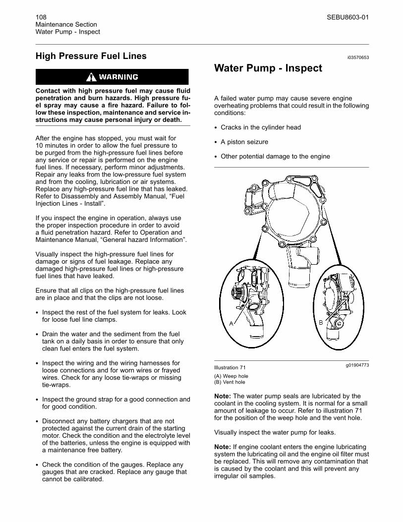
108 SEBU8603-01Maintenance SectionWater Pump - Inspect
High Pressure Fuel Lines
Contact with high pressure fuel may cause fluidpenetration and burn hazards. High pressure fu-el spray may cause a fire hazard. Failure to fol-low these inspection, maintenance and service in-structions may cause personal injury or death.
After the engine has stopped, you must wait for10 minutes in order to allow the fuel pressure tobe purged from the high-pressure fuel lines beforeany service or repair is performed on the enginefuel lines. If necessary, perform minor adjustments.Repair any leaks from the low-pressure fuel systemand from the cooling, lubrication or air systems.Replace any high-pressure fuel line that has leaked.Refer to Disassembly and Assembly Manual, “FuelInjection Lines - Install”.
If you inspect the engine in operation, always usethe proper inspection procedure in order to avoida fluid penetration hazard. Refer to Operation andMaintenance Manual, “General hazard Information”.
Visually inspect the high-pressure fuel lines fordamage or signs of fuel leakage. Replace anydamaged high-pressure fuel lines or high-pressurefuel lines that have leaked.
Ensure that all clips on the high-pressure fuel linesare in place and that the clips are not loose.
• Inspect the rest of the fuel system for leaks. Lookfor loose fuel line clamps.
• Drain the water and the sediment from the fueltank on a daily basis in order to ensure that onlyclean fuel enters the fuel system.
• Inspect the wiring and the wiring harnesses forloose connections and for worn wires or frayedwires. Check for any loose tie-wraps or missingtie-wraps.
• Inspect the ground strap for a good connection andfor good condition.
• Disconnect any battery chargers that are notprotected against the current drain of the startingmotor. Check the condition and the electrolyte levelof the batteries, unless the engine is equipped witha maintenance free battery.
• Check the condition of the gauges. Replace anygauges that are cracked. Replace any gauge thatcannot be calibrated.
i03570653
Water Pump - Inspect
A failed water pump may cause severe engineoverheating problems that could result in the followingconditions:
• Cracks in the cylinder head
• A piston seizure
• Other potential damage to the engine
g01904773Illustration 71(A) Weep hole(B) Vent hole
Note: The water pump seals are lubricated by thecoolant in the cooling system. It is normal for a smallamount of leakage to occur. Refer to illustration 71for the position of the weep hole and the vent hole.
Visually inspect the water pump for leaks.
Note: If engine coolant enters the engine lubricatingsystem the lubricating oil and the engine oil filter mustbe replaced. This will remove any contamination thatis caused by the coolant and this will prevent anyirregular oil samples.

SEBU8603-01 109Maintenance SectionWater Pump - Inspect
The water pump is not a serviceable item. In order toinstall a new water pump, refer to the Disassemblyand Assembly Manual, “Water Pump - Remove andInstall”.
110 SEBU8603-01Warranty SectionWarranty Information
Warranty Section
Warranty Informationi04021284
Federal Emission ControlWarranty
Emissions WarrantyThe 1206E-E66TA diesel engine is a nonroadcompression ignition engine. Perkins EngineCompany limited warrants to the initial owner and tothe subsequent owner of the 1206E-E66TA dieselengine that such an engine is:
1. Designed, built, and equipped so that the engineconforms, at the time of sale, with all applicableregulations adopted by the United StatesEnvironmental Protection Agency (EPA).
2. Free from defects in materials and workmanshipin specific emission-related parts for the followingperiod:
• The warranty period is for 3000 hours or for 5years, whichever occurs first. After the date ofdelivery to the owner that operates the engine.
If an emission-related part fails during any of thewarranty periods, the part will be repaired or replaced.Any such part repaired or replaced under warranty iswarranted for the remainder of the warranty period.
During the term of this warranty, Perkins EngineCompany limited will provide through a Perkinsdistributor or your Perkins dealer or otherestablishment authorized by Perkins EngineCompany limited , repair or replacement of anywarranted part at no charge to the engine owner.
In an emergency, repairs may be performed atany service establishment, or by the owner, usingany replacement part. Perkins recommended thatemission-related parts be replaced with genuinePerkins Engine Company limited parts.
Perkins Engine Company limited will reimburse theowner. This reimbursement will include diagnosticcharges for such an emergency repair. Theseexpenses shall not exceed the Perkins EngineCompany limited suggested retail price for allwarranted parts replaced, and labor charges basedon Perkins Engine Company limited recommendedtime allowance for the warranty repair and thegeographically appropriate hourly labor rate.
As a condition of reimbursement, replaced parts andreceipted invoices must be presented at a place ofbusiness of a Perkins distributor or your Perkinsdealer. Or other establishment authorized by PerkinsEngine Company limited
This warranty covers the following emission-relatedparts and components:
• Turbocharger System
• Inlet Manifold
• Fuel Injection System
• Crankcase Ventilation System
• Electronic Engine Control System
• Engine Aftertreatment System
• NOx Reduction System
• Aftertreatment Regeneration Device
• Miscellaneous valves, switches, hoses, clamps,connectors, tubing, and sealing devices that areused in the above systems
Limitations and Responsibilities
The warranty is subject to the following conditions:
Perkins Engine Company limited Responsibilities
During the emission warranty period, if a defect inmaterial or workmanship of an emission-related partor component is found, Perkins Engine Companylimited will provide the following:
• New, Remanufactured or repaired parts and/orcomponents, approved pursuant to EPARegulations, required to correct the defect.
• Reasonable and customary labor, during normalworking hours that is required to make the warrantyrepair. This will include labor in order to remove anengine and install the engine, if necessary.
SEBU8603-01 111Warranty Section
Warranty Information
Note: Items that are replaced under this warrantybecome the property of Perkins Engine Companylimited .
Owner Responsibilities
During the emission warranty period, the owner isresponsible for the following items:
• The costs in order to investigate complaints whichare not caused by a defect in Perkins EngineCompany limited material or Perkins EngineCompany limited workmanship.
• Providing timely notice of a warrantable failure andpromptly making the product available for repair
Limitations
Perkins Engine Company limited is not responsiblefor resultant damages to an emission-related part orcomponent resulting from the following items:
• Any application or any installation that PerkinsEngine Company limited deems improper.
• Attachments, accessory items, or parts not soldnor approved by Perkins Engine Company limited
• Improper engine maintenance, repair, or abuse.
• Use of improper fuel, lubricants, or fluids.
• Owners unreasonable delay in making the productavailable after being notified of a potential productproblem.
This warranty is in addition to Perkins EngineCompany limited standard warranty, applicable to theengine product involved.
Remedies under this warranty are limited to theprovision of material and services as specified herein.Perkins Engine Company limited is not responsiblefor incidental or consequential damages, includingbut not limited to downtime or loss-of-use of engine.
i04141345
Emissions WarrantyInformation
• EPA ______________________________________ United StatesEnvironmental Protection Agency
• CARB _____________ California Air Resources Board
Note: The warranty of the engine applies to enginesthat are operated within the areas of the worldwhere the following regulations apply: US EPA Tier 4Interim, EU Stage IIIB or Japanese MLIT Step 4. Ifan engine is operated in regions of the world wherethese regulations do not apply the warranty will bevoid. Contact your Perkins dealer or your Perkinsdistributor for more information.
Maintenance RecommendationsPerkins Engines Company Limited engines arecertified by the EPA and the CARB in order to complywith exhaust emission standards and gaseousemission standards that are prescribed by the law atthe time of manufacture.
Efficiency of the emission control and the engineperformance depends on adherence to properoperation and maintenance recommendations anduse of recommended fuels and lubricating oils.According to recommendations, major adjustmentsand repairs should be made by your authorizedPerkins distributor or your authorized Perkins dealer.
Various chemical fuel additives which claim to reducevisible smoke are available commercially. Althoughadditives have been used to solve some isolatedsmoke problems in the field, additives are notrecommended for general use. The engines shouldbe certified without smoke depressants according tofederal smoke regulations.
Take corrective steps immediately after worn partswhich may affect the emissions level are discoveredin order to ensure the proper operation of theemission control systems. The use of genuinePerkins components is recommended. If the owneruses non-Perkins components, then the non-Perkinscomponents must not adversely affect the emissionslevel of the engine.
For information on the use of Aftermarket Productsand Perkins Engines, refer to this Operation andMaintenance Manual, “Engine Description”.
Regular maintenance intervals with a specialemphasis on the following items are necessary inorder to keep exhaust emissions within acceptablelimits for the useful life of the engine. Refer to theOperation and Maintenance Manual, “Severe ServiceApplication - Check” topic (Maintenance Section).If the engine is operating under severe conditions,adjust the maintenance schedule accordingly.See your authorized Perkins distributor/dealer inorder to help analyze your specific application,operating environment, and maintenance scheduleadjustments.
112 SEBU8603-01Warranty SectionWarranty Information
The following information is an explanation ofmaintenance items for emission-related components.See the Operation and Maintenance Manual,“Maintenance Interval Schedule” (MaintenanceSection) for the specific interval for the followingitems.
ENGINE AFTERTREATMENT SYSTEM – TheEngine Aftertreatment Systems are sensitive to thetype of fuel and lubricants that is used. Also, theengine aftertreatment systems are sensitive to theoperating schedule. Low quality fuel, lubricants, orfluids may cause increases in exhaust back pressureor clogging resulting in loss of power. An authorizedPerkins distributor/dealer can determine if the engineaftertreatment systems require a service.
NOx Reduction System (NRS) – The NRS ismonitored. An authorized Perkins distributor/dealercan determine if the NRS needs service.
FUEL INJECTORS – Fuel injector tips are subject towear as a result of fuel contamination. This damagecan cause the following conditions: an increase infuel consumption, black smoke, misfire, and roughrunning engine. The fuel injector should be inspected,tested, and replaced, if necessary. Fuel injectors canbe tested by an authorized Perkins distributor/dealer .
TURBOCHARGER – Refer to this Operation andMaintenance Manual, “Turbocharger - Inspect” forinformation on inspection of the turbocharger.
ELECTRONIC ENGINE CONTROL (ECM) – TheECM is the control computer of the engine. The ECMprovides power to the electronics. The ECM monitorsdata that is input from the sensors of the engine.The ECM acts as a governor in order to control thespeed and the power of the engine. The ECM adjustsinjection timing and fuel pressure for the best engineperformance, the best fuel economy, and the bestcontrol of exhaust emissions.
Erratic behavior of the engine may indicate a needfor repair to the ECM. Your Perkins distributor/dealeris equipped with the necessary tools, personnel, andprocedures in order to perform this service.
The owner is encouraged to keep adequatemaintenance records. However, the absence of suchrecords will not invalidate the warranty. Refer to theOperation and Maintenance Manual, “MaintenanceLog” (Reference Materials Section).
The owner may perform routine maintenance,repairs, and other work that is outside of the warranty.The work may be done at any repair facility. Suchwork does not need to be performed at a designatedstation that is determined by the warranty in order forthe warranty to remain in force.
i04021417
California Emission ControlWarranty Statement
Emissions WarrantyThe 1206E-E66TA is a nonroad compression ignitionengine.
The California Air Resources Board (CARB) andPerkins Engines Company Limited are pleased toexplain the emission control system warranty on your1206E-E66TA diesel engine.
In California, new motor vehicle engines must bedesigned, built, and equipped in order to meetthe state's stringent anti-smog standards. PerkinsEngines Company Limited must warrant the emissioncontrol system on your engine for the duration of timelisted below. Provided, there has not been any abuse,neglect, or improper maintenance of your engine oryour engine aftertreatment system.
Perkins Engines Company Limited warrants to theinitial owner and to the subsequent owner of the1206E-E66TA diesel engine that such an engine is:
1. Designed, built, and equipped so that theengine conforms, at the time of sale, with allapplicable regulations adopted by the CaliforniaAir Resources Board (CARB).
2. Free from defects in materials and workmanshipin specific emission-related parts for the followingperiod:
• The warranty period is for 3000 hours or for 5years, whichever occurs first. After the date ofdelivery to the owner that operates the engine.
If an emission-related part fails during any ofthe warranty periods, the part will be repairedor replaced. Any such part repaired or replacedunder warranty is warranted for the remainder ofthe warranty period.
During the term of this warranty, Perkins EnginesCompany Limited will provide through a Perkinsdistributor or your Perkins dealer or otherestablishment authorized by Perkins EnginesCompany Limited , repair or replacement of anywarranted part at no charge to the engine owner.
In an emergency, repairs may be performed atany service establishment, or by the owner, usingany replacement part. Perkins recommended thatemission-related parts be replaced with genuinePerkins Engines Company Limited parts.

SEBU8603-01 113Warranty Section
Warranty Information
Perkins Engines Company Limited will reimbursethe owner. This reimbursement will includediagnostic charges for such an emergency repair.These expenses shall not exceed the PerkinsEngines Company Limited suggested retail pricefor all warranted parts replaced, and labor chargesbased on Perkins Engines Company Limitedrecommended time allowance for the warrantyrepair and the geographically appropriate hourlylabor rate.
As a condition of reimbursement, replaced partsand receipted invoices must be presented at aplace of business of a Perkins distributor or yourPerkins dealer or other establishment authorizedby Perkins Engines Company Limited .
This warranty covers the followingemission-related parts and components:
• Turbocharger System
• Inlet Manifold
• Fuel Injection System
• Crankcase Ventilation System
• Electronic Engine Control System
• Engine Aftertreatment System
• NOx Reduction System
• Aftertreatment Regeneration Device
• Miscellaneous valves, switches, hoses, clamps,connectors, tubing, and sealing devices that areused in the above systems
Limitations and Responsibilities
The warranty is subject to the following conditions:
Perkins Engines Company LimitedResponsibilities
During the emission warranty period, if a defect inmaterial or workmanship of an emission-related partor component is found, Perkins Engines CompanyLimited will provide the following:
• New, Remanufactured or repaired parts and/orcomponents, approved pursuant to (CARB)Regulations, required to correct the defect.
• Reasonable and customary labor, during normalworking hours that is required to make the warrantyrepair. Included will be labor in order to remove anengine and install the engine, if necessary.
Note: Items that are replaced under this warrantybecome the property of Perkins Engines CompanyLimited .
Owner Responsibilities
During the emission warranty period, the owner isresponsible for the following items:
• The costs in order to investigate complaints whichare not caused by a defect in Perkins EnginesCompany Limited material or Perkins EnginesCompany Limited workmanship.
• Providing timely notice of a warrantable failure andpromptly making the product available for repair
Limitations
Perkins Engines Company Limited is not responsiblefor resultant damages to an emission-related part orcomponent resulting from the following items:
• Any application or any installation that PerkinsEngines Company Limited deems improper.
• Attachments, accessory items, or parts not sold norapproved by Perkins Engines Company Limited
• Improper engine maintenance, repair, or abuse.
• Use of improper fuel, lubricants, or fluids.
• Owners unreasonable delay in making the productavailable after being notified of a potential productproblem.
This warranty is in addition to Perkins EnginesCompany Limited standard warranty, applicable tothe engine product involved.
Remedies under this warranty are limited to theprovision of material and services as specified herein.Perkins Engines Company Limited is not responsiblefor incidental or consequential damages, includingbut not limited to downtime or loss-of-use of engine.
114 SEBU8603-01Reference Information SectionReference Materials
Reference InformationSection
Reference Materialsi04224089
Engine Protection Plans(Extended Service Contract)
Extended Service Contracts-purchased in minutes,protected for years.
Extended Service Contracts (ESC) protect you fromthe stress that unexpected repair work brings to yourlife by covering the cost of getting your engine upand running again. Unlike other extended warranties,Perkins Platinum ESC protects you against allcomponent part failures.
Purchase peace of mind from only £0.03 / $0.05 /euro 0.04 a day and let an ESC make your dreamsa reality.
Why buy an Extended Service Contract?
1. No surprises - total protection from unexpectedrepair cost (parts, labor, and travel).
2. Enjoy longer lasting product support from Perkinsglobal network.
3. Genuine Perkins parts ensure continued engineperformance.
4. Highly trained technicians carry out all repairs.
5. Transferable coverage should you sell yourmachine.
Flexible coverage provides the right level of protectionfor your Perkins Engine. Coverage can be extendedto 2 years/ 1,000 hours right up to 10 year/ 40,000
You can buy an ESC at any time during standardwarranty - even the last day!
Each Perkins Distributor has highly trained andexperienced Perkins Product Support ServiceTechnicians. The Support Service are equipped, andavailable around the clock to get your engine runningagain with the minimum of downtime. Buying an ESCmeans that you get all this for free.
To purchase an Extended Service Contract, is quickand simple! Contact your local Perkins Distributornow and the distributor can provide you with a quotein minutes. You can locate your nearest PerkinsDistributor by visiting:
www.perkins.com
NOTICEDependant upon engine type and application.
SEBU8603-01 115Index Section
Index
A
After Starting Engine ............................................. 53After Stopping Engine............................................ 56Aftercooler Core - Clean/Test (Air-To-AirAftercooler) .......................................................... 79Aftercooler Core - Inspect...................................... 79Alternator - Inspect ................................................ 79Alternator and Fan Belts - Replace ....................... 79
B
Battery - Replace................................................... 79Battery Electrolyte Level - Check .......................... 80Battery or Battery Cable - Disconnect ................... 80Before Starting Engine .................................... 16, 51Belt - Inspect.......................................................... 81Belt Tensioner - Inspect ......................................... 81Burn Prevention...................................................... 11Batteries............................................................. 12Coolant................................................................ 11Induction System ................................................ 11Oils...................................................................... 11
C
California Emission Control Warranty Statement .. 112Emissions Warranty .......................................... 112
Cold Weather Operation........................................ 58Hints for Cold Weather Operation...................... 58Idling the Engine ................................................ 59Recommendations for Coolant Warm Up .......... 59Recommendations for the Coolant .................... 58Viscosity of the Engine Lubrication Oil............... 58
Cold Weather Starting ........................................... 51Configuration Parameters...................................... 47Customer Specified Parameters ........................ 48System Configuration Parameters ..................... 47
Cooling System Coolant (Commercial Heavy-Duty) -Change ................................................................ 82Drain .................................................................. 82Fill ...................................................................... 83Flush .................................................................. 83
Cooling System Coolant (ELC) - Change.............. 83Drain .................................................................. 84Fill ...................................................................... 85Flush .................................................................. 84
Cooling System Coolant Level - Check ................. 85Engines With a Coolant Recovery Tank............. 85Engines Without a Coolant Recovery Tank........ 86
Cooling System Supplemental Coolant Additive(SCA) - Test/Add.................................................. 86Add the SCA, If Necessary ................................ 87Test for SCA Concentration ............................... 86
Cooling System Water Temperature Regulator -Replace................................................................ 87
Crushing Prevention and Cutting Prevention ........ 14
D
Diagnostic Flash Code Retrieval ........................... 45Diagnostic Lamp.................................................... 45Driven Equipment - Check..................................... 88
E
Electrical System................................................... 17Grounding Practices .......................................... 17
Emergency Stopping ............................................. 56Emissions Certification Film .................................. 28Emissions Warranty Information........................... 111Maintenance Recommendations ...................... 111
Engine - Clean....................................................... 88Aftertreatment .................................................... 88
Engine Air Cleaner Element (Dual Element) -Clean/Replace ..................................................... 89Cleaning the Primary Air Cleaner Elements ...... 90Servicing the Air Cleaner Elements ................... 89
Engine Air Cleaner Element (Single Element) -Inspect/Replace................................................... 91Engine Air Cleaner Service Indicator - Inspect...... 91Test the Service Indicator................................... 92
Engine Air Precleaner - Check/Clean.................... 92Engine Crankcase Breather Element - Replace.... 92Bottom Service................................................... 94Check the System.............................................. 95Top Service ........................................................ 93
Engine Description ................................................ 24Aftermarket Products and Perkins Engines ....... 26Aftertreatment System ....................................... 25Electronic Engine Features................................ 25Engine Cooling and Lubrication ......................... 25Engine Diagnostics ............................................ 25Engine Service Life ............................................ 26Engine Specifications......................................... 24
Engine Diagnostics................................................ 45Engine Electronics................................................. 18Engine Mounts - Inspect........................................ 95Engine Oil and Filter - Change .............................. 96Drain the Engine Lubricating Oil ........................ 96Fill the Oil Pan.................................................... 97Replace the Oil Filter ......................................... 97
Engine Oil Level - Check....................................... 95Engine Oil Sample - Obtain ................................... 96Obtain the Sample and the Analysis.................. 96
Engine Operation................................................... 54Reduction of Particulate Emissions ................... 54
Engine Operation with Active Diagnostic Codes ... 47Engine Operation with Intermittent DiagnosticCodes .................................................................. 47Engine Protection Plans (Extended ServiceContract) ............................................................. 114
116 SEBU8603-01Index Section
Engine Shutoffs and Engine Alarms...................... 43Alarms................................................................ 43Shutoffs.............................................................. 43Testing................................................................ 44
Engine Starting ................................................ 16, 51Engine Stopping .............................................. 16, 56
F
Fault Logging......................................................... 46Features and Controls ........................................... 34Federal Emission Control Warranty...................... 110Emissions Warranty .......................................... 110
Fire Prevention and Explosion Prevention ............ 12Fire Extinguisher ................................................ 13Lines, Tubes and Hoses .................................... 13
Fluid Recommendations............................ 62, 67, 69Diesel Fuel Characteristics ................................ 72Diesel Fuel Requirements.................................. 69ELC Cooling System Maintenance .................... 64Engine Oil .......................................................... 67General Coolant Information.............................. 62General Information ........................................... 69General Lubricant Information ........................... 67
Foreword ................................................................. 4California Proposition 65 Warning ....................... 4Literature Information........................................... 4Maintenance ........................................................ 4Maintenance Intervals.......................................... 4Operation ............................................................. 4Overhaul .............................................................. 4Safety................................................................... 4
Fuel and the Effect from Cold Weather ................. 60Fuel Conservation Practices.................................. 55Fuel Related Components in Cold Weather .......... 61Fuel Filters ......................................................... 61Fuel Heaters ...................................................... 61Fuel Tanks.......................................................... 61
Fuel System - Prime.............................................. 98Fuel System Primary Filter (Water Separator)Element - Replace ............................................... 98In-line Strainer.................................................. 100Install the Element ........................................... 100Remove the Element ......................................... 98
Fuel System Primary Filter/Water Separator -Drain .................................................................. 100Fuel System Secondary Filter - Replace............. 101Install the Element ........................................... 102Remove the Element ....................................... 101
Fuel Tank Water and Sediment - Drain ............... 102Drain the Water and the Sediment................... 102Fuel Storage Tanks.......................................... 103Fuel Tank ......................................................... 102
G
Gauges and Indicators .......................................... 32Indicator Lamps ................................................. 33Instrument panels and Displays......................... 33
General Hazard Information .................................... 8Asbestos Information ......................................... 10Containing Fluid Spillage ................................... 10Dispose of Waste Properly ................................. 11Fluid Penetration.................................................. 9Pressurized Air and Water ................................... 9
H
High Pressure Fuel Lines ...................................... 14Hoses and Clamps - Inspect/Replace ................. 103Replace the Hoses and the Clamps ................ 103
I
Important Safety Information ................................... 2
L
Lifting and Storage ................................................ 29
M
Maintenance Interval Schedule ............................. 78Maintenance Recommendations........................... 76Maintenance Section............................................. 62Model View Illustrations......................................... 20Engine Aftertreatment System........................... 24Engine views...................................................... 20
Model Views .......................................................... 20Monitoring System................................................. 34Programmable Options and SystemsOperation ......................................................... 34
Monitoring System (Table for the Indicatorlamps) .................................................................. 36Mounting and Dismounting.................................... 14
O
Operation Section.................................................. 29Overspeed............................................................. 44
P
Plate Locations and Film Locations (EngineAftertreatment System )....................................... 27Product Identification Information .......................... 27Product Information Section .................................. 20Product Lifting (Clean Emission Module) .............. 30Product Lifting (Engine) ......................................... 29Product Storage (Engine and Aftertreatment) ....... 30Condition for Storage......................................... 30

SEBU8603-01 117Index Section
R
Radiator - Clean .................................................. 104Reference Information Section ............................. 114Reference Materials ............................................. 114Reference Numbers .............................................. 27Record for Reference......................................... 27
Refill Capacities..................................................... 62Cooling System.................................................. 62Lubrication System ............................................ 62
S
Safety Messages..................................................... 5(1) Universal Warning .......................................... 5(2) Hand (High Pressure)..................................... 6Ether Warning ...................................................... 7
Safety Section ......................................................... 5Self-Diagnostics..................................................... 45Sensors and Electrical Components ..................... 37Sensors and Electrical Components(Aftertreatment).................................................... 37Severe Service Application - Check .................... 105Environmental Factors ..................................... 105Incorrect Maintenance Procedures.................. 105Incorrect Operating Procedures....................... 105
Starting Motor - Inspect ....................................... 105Starting the Engine................................................ 51Starting the Engine ............................................ 51
Starting with Jump Start Cables ............................ 52Stopping the Engine .............................................. 56System Pressure Release..................................... 76Coolant System.................................................. 76Engine Oil .......................................................... 76Fuel System....................................................... 76
T
Table of Contents..................................................... 3Turbocharger - Inspect ........................................ 106
W
Walk-Around Inspection ...................................... 107High Pressure Fuel Lines................................. 108Inspect the Engine for Leaks and for LooseConnections ................................................... 107Inspect the Tube of the Crankcase Breather ... 107
Warranty Information ............................................ 110Warranty Section .................................................. 110Water Pump - Inspect.......................................... 108Welding on Engines with Electronic Controls ........ 76

118 SEBU8603-01Index Section
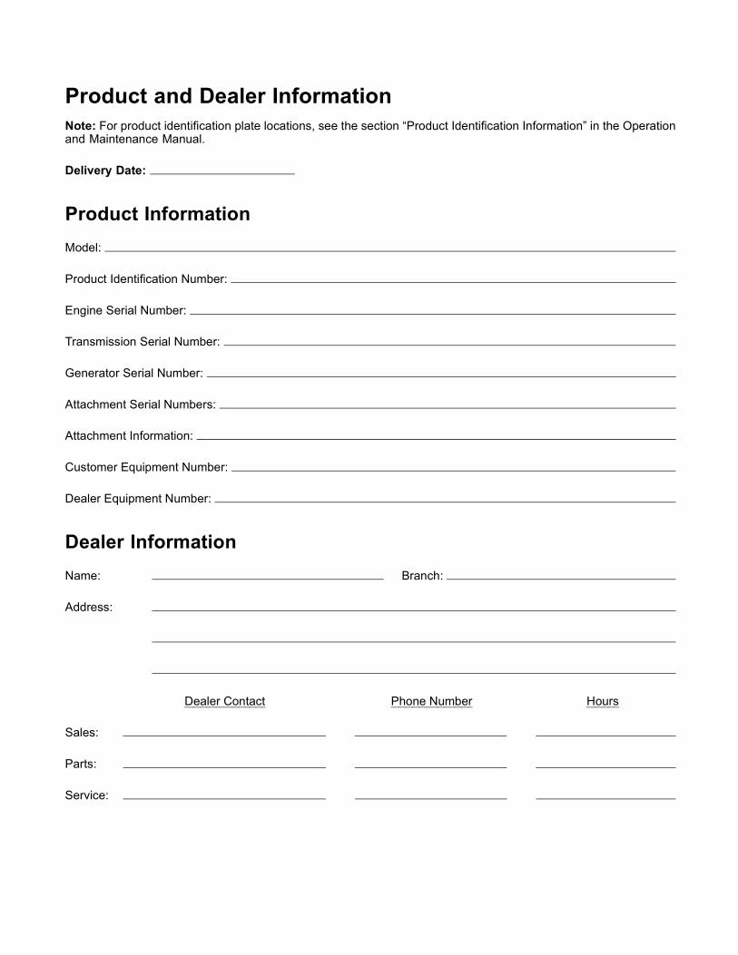
Product and Dealer InformationNote: For product identification plate locations, see the section “Product Identification Information” in the Operationand Maintenance Manual.
Delivery Date:
Product InformationModel:
Product Identification Number:
Engine Serial Number:
Transmission Serial Number:
Generator Serial Number:
Attachment Serial Numbers:
Attachment Information:
Customer Equipment Number:
Dealer Equipment Number:
Dealer InformationName: Branch:
Address:
Dealer Contact Phone Number Hours
Sales:
Parts:
Service:

©2011 Perkins Engines Company LimitedAll Rights Reserved Printed in U.K.