12.4% epu nuclear page 22 first concrete page 50 plant...
TRANSCRIPT
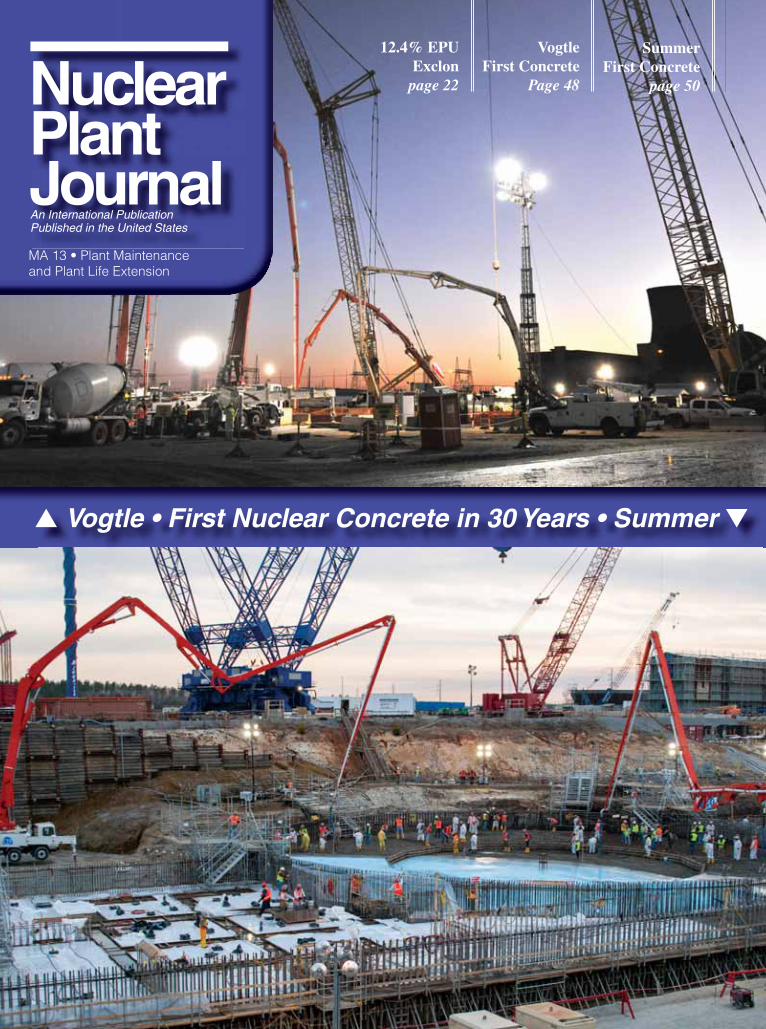
▲ Vogtle • First Nuclear Concrete in 30 Years • Summer ▼
NuclearPlantJournalMA 13 • Plant Maintenance and Plant Life Extension
SummerFirst Concrete
page 50
VogtleFirst Concrete
Page 48
12.4% EPU Exclonpage 22


Parts availability makes obsolescence obsolete.
Parts Asset Management Solutions(PAMS) only from GE Hitachi.
Now boiling water reactor operators can get the parts they need to stay current and operating effi ciently. With
industry-leading technical experts that can identify parts needs and develop solutions for optimal performance,
GE Hitachi has helped our customers solve over 250 obsolescence issues with more than 650 replacement
parts. Delivered within 24 hours, every time. PAMS provides the kind of critical support that’s helping
maximize uptime – something that never goes out of date.
ge.com/nuclear
72233_nuclear_pams_ad_npj.indd 1 2/13/13 8:39 AM

Nuclear Plant Journal, March-April 2013 NuclearPlantJournal.com 5
Plant Maintenance & Plant Life Extension Issue
®
Articles & ReportsSequoyah License Renewal 18 By Tennessee Valley Authority
Successes & Challenges of Extended Power Uprate 20 By Dave Dellario, Phil Amway, and Kathy Picciott, Constellation Energy Nuclear Group Peach Bottom’s 12.4% EPU 22 By Michael Massaro, Exelon Generation A Safe Plant for the 21st Century 24 By Anthony Robinson, AREVA Inc. Passively Safe Plant 28 By William (Ed) Cummins, Westinghouse Electric Company Old Reactors, New Tricks 30 An excerpt from IEEE Spectrum Magazine
On-line Monitoring 32 By Richard Rusaw, Electric Power Research Institute Industry InnovationsSpent Fuel Pool Monitoring 35 By H.M. Hashemian, Jonathan Edwards, Micah McFarland, and W.S. Johnson, Analysis and Measurement Services Corporation Robotic Pipe Inspection to Meet License Renewal Commitments 38 By David Bremer, Cooper Nuclear Station
Mastering Breaker Maintenance 42 By Gregory Lichty, Public Service Electric and Gas Company and Dave Davis, AZZ | NLI
A Solution for Aging BWR Plants: Jet Pump Anti-Vibration Solution 46 By Bret Nelson, GE Hitachi Nuclear Energy Plant Profi le Vogtle First Nuclear Concrete 48 By Georgia Power Summer First Nuclear Concrete 50 By South Carolina Electric & Gas Departments
Nuclear Plant JournalMarch-April 2013, Volume 31 No. 2
Nuclear Plant Journal is published by EQES, Inc. six times a year in January-February, March-April, May-June, July-August, September-October, and November-December (the Annual Directory).
The subscription rate for non-qualifi ed readers in the United States is $150.00 for six issues per year. The additional air mail cost for non-U.S. readers is $30.00. Payment may be made by American Express®, Master Card®, VISA® or check and should accompany the order. Checks may be made payable to "EQES, Inc." Checks not drawn on a United States bank should include an additional $45.00 service fee. All inquiries should be ad-dressed to Nuclear Plant Journal, 1400 Opus Place, Suite 904, Downers Grove, IL 60515; Phone: (630) 858-6161, ext. 103; Fax: (630) 852-8787, email: [email protected]. 30 years of Journal issues are available online through the Journal website www.NuclearPlantJournal.com (search box on the right-top) for a nominal fee of $25 per issue. Contact: Anu Agnihotri, email: [email protected]
© Copyright 2013 by EQES, Inc.
ISSN: 0892-2055
Nuclear Plant Journal is a registered trademark of EQES, Inc.Printed in the USA.
Staff
Senior Publisher and EditorNewal K. Agnihotri, P.E.
Publisher and Sales ManagerAnu Agnihotri
Assistant Editor and Marketing ManagerMichelle Gaylord
Administrative Assistant QingQing Zhu
Publishing Assistant Ned Swanson
*Current Circulation: Total: 12,273 Utilities: 2,904*All circulation information is subject to BPA Worldwide, Business audit.
31st Year of Publication
Mailing Identifi cation StatementNuclear Plant Journal (ISSN 0892-2055) is published bimonthly; January-February, March-
April, May-June, July-August, September-October, and November-December by EQES, Inc., 1400 Opus Place, Suite 904, Downers Grove, IL 60515. The printed version of the Journal is available cost-free to qualifi ed readers in the United States and Canada. The digital version is available cost-free to qualifi ed readers worldwide. The subscription rate for non-qualifi ed readers is $150.00 per year. The cost for non-qualifi ed, non-U.S. readers is $180.00. Periodicals (permit number 000-739) postage paid at the Downers Grove, IL 60515 and additional mailing offi ces. POSTMASTER: Send address changes to Nuclear Plant Journal (EQES, Inc.), 1400 Opus Place, Suite 904, Downers Grove, IL 60515, U.S.A.
New Energy News 8
Utility, Industry & Corporation 9
New Products, Services & Contracts 12
New Documents 14
Research & Development 16
Meeting & Training Calendar 47
Journal ServicesList of Advertisers 6
Advertiser Web Directory 50
On The CoverVogtle Unit 3 and V.C. Summer Unit 2 have completed the placement of basemat structural concrete. See pages 48 and 50 for profi les.
72233_nuclear_pams_ad_npj.indd 1 2/13/13 8:39 AM
6 NuclearPlantJournal.com Nuclear Plant Journal, March-April 2013
Nuclear Plant Journal Rapid Response Fax Form
To: _________________________ Company: __________________ Fax: ___________________
From: _______________________ Company: __________________ Fax: ___________________
Address:_____________________ City: _______________________ State: _____ Zip: _________
Phone: ______________________ E-mail: _____________________
I am interested in obtaining information on: __________________________________________________
Comments: _____________________________________________________________________________
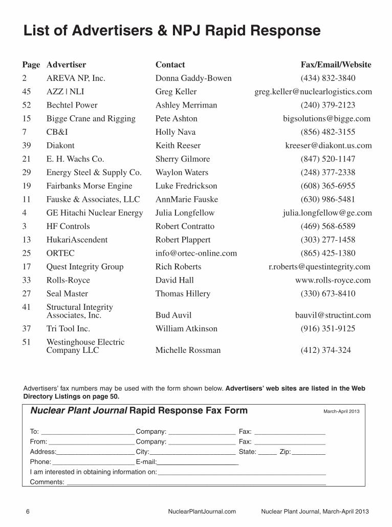
List of Advertisers & NPJ Rapid Response
March-April 2013
Advertisers’ fax numbers may be used with the form shown below. Advertisers’ web sites are listed in the Web Directory Listings on page 50.
Page Advertiser Contact Fax/Email/Website
2 AREVA NP, Inc. Donna Gaddy-Bowen (434) 832-3840
45 AZZ | NLI Greg Keller [email protected]
52 Bechtel Power Ashley Merriman (240) 379-2123
15 Bigge Crane and Rigging Pete Ashton [email protected]
7 CB&I Holly Nava (856) 482-3155
39 Diakont Keith Reeser [email protected]
21 E. H. Wachs Co. Sherry Gilmore (847) 520-1147
29 Energy Steel & Supply Co. Waylon Waters (248) 377-2338
19 Fairbanks Morse Engine Luke Fredrickson (608) 365-6955
11 Fauske & Associates, LLC AnnMarie Fauske (630) 986-5481
4 GE Hitachi Nuclear Energy Julia Longfellow [email protected]
3 HF Controls Robert Contratto (469) 568-6589
13 HukariAscendent Robert Plappert (303) 277-1458
25 ORTEC [email protected] (865) 425-1380
17 Quest Integrity Group Rich Roberts [email protected]
33 Rolls-Royce David Hall www.rolls-royce.com
27 Seal Master Thomas Hillery (330) 673-8410
41 Structural Integrity Associates, Inc. Bud Auvil [email protected]
37 Tri Tool Inc. William Atkinson (916) 351-9125
51 Westinghouse Electric Company LLC Michelle Rossman (412) 374-324

A World of SolutionsVisit www.CBI.com
A Milestone AchievementFirst New Nuclear ConstructionCB&I congratulates South Carolina Electric & Gas (SCE&G) and Southern
Company for their successful completion of the fi rst new construction nuclear
concrete to be poured in the U.S. in three decades. These accomplishments at
the V.C. Summer and Vogtle projects are extraordinary milestones not only for
the projects themselves, but for the entire nuclear industry.
For more than 60 years, CB&I has provided comprehensive services to the
nuclear power industry. We’re proud to continue that tradition with these
successful projects.
18M
0320
13D

8 NuclearPlantJournal.com Nuclear Plant Journal, March-April 2013
New Energy
Grid ConnectionThere was a successful grid
connection of the Unit 1 of Hongyanhe Nuclear Power Plant (HYH NPP), the fi rst nuclear power plant ever in Northeast of China, marked by the initiation of its startup for operation.
Started on August 18, 2007, the Unit 1 of HYH NPP went through the milestones of civil works, equipment installation, system commissioning, fuel loading, unit criticality and turbine run-up before fi nalizing the on-grid process.
All the 4 units of Phase I of HYH NPP, a NPP envisaged to consist of 6 units, are estimated to complete for operation in 2015. After that, the annual electricity generation of the 4 units will be up to 30 billion kWh, accounting for about 16% of the annual electricity consumption in Liaoning Province.
The on-grid operation of HYH will lead to optimized power supply structure in Liaoning Province while helping emission reduction in the region.
Hongyanhe will use the CPR-1000 (intellectual property rights are retained by AREVA).
HYH NPP, the fi rst nuclear power plant in Northeast of China, is a joint venture of China Guangdong Nuclear Power Group (CGN), CPIC and Dalian Construction Investment Group.
Contact: website: http://www.cgnpc.com.cn
Hinkley PointAfter a year-long examination,
On March 19, 2013 the UK Planning Inspectorate granted EDF Energy consent to construct a new nuclear power station at Hinkley Point in Somerset, United Kingdom. This decision follows three years of in-depth consultation with local communities and the approval was also met with wide political consensus in the House of Commons.
The process was an immense undertaking to examine the impact of the construction and operation of the site on the community and environment. It included detailed studies on housing,
transport and jobs and demonstrated EDF Energy’s commitment to be open, transparent and to listen.
The approval by the Secretary of State for Energy and Climate Change also means that Hinkley Point C is the fi rst piece of national infrastructure on this scale to be approved under the new 2008 Planning Act. This rigorous process was achieved in time.
This remarkable achievement now needs to be matched by the fi nalization of a contract for the electricity to be produced at Hinkley Point C. Swift success in negotiations with Government over this Contract for Difference is the key to unlocking the investment needed.
EDF Energy Chief Executive Vincent de Rivaz said: “Receiving permission to construct a new nuclear power station at Hinkley Point C is a huge achievement, which represents years of hard work. It refl ects an extraordinary level of professionalism and work from EDF Energy’s planning team, the Planning Inspectorate, local authorities and a wide range of stakeholders.
“The success of this pioneering project will kick start the new nuclear program in the UK and is expected to lead to lower costs for successive UK nuclear plants.”
Contact: Tim McCoy, telephone: 07875119378, email: [email protected].
BarakahConstruction of the Emirates
Nuclear Energy Corporation’s (UAE) fi rst nuclear energy reactor continues to progress, with the installation of the Containment Liner Plate (CLP) in the Reactor Containment Building for Barakah Unit 1 on March, 2013. The CLP is one of the many defense-in-depth barriers that ensure the safety of nuclear energy plants.
The Emirates Nuclear Energy Corporation (ENEC) and the Korea Electric Power Corporation (KEPCO) installed the fi rst modularized sections of the 2000 ton steel cylinder. The installation was the culmination of months of work. With the CLP installation proceeding, ENEC and KEPCO remain on track to deliver the country’s fi rst nuclear energy reactor, Barakah Unit 1, in 2017. A total of four nuclear energy reactors are set to be constructed by 2020, producing a
signifi cant portion of the UAE’s energy needs and saving up to 12 million tons in carbon emissions every year.
Contact: email: [email protected].
FinlandFinnish utility Fennovoima has
applied for three environmental permits involving construction of structures in the Baltic Sea needed for its planned nuclear reactor.
The company wants to build the Hanhikivi-1 nuclear unit in the Pyhäjoki municipality in northern Finland.
The statement said the applications were fi led with the Northern Finland Regional State Administrative Agency.
One permit is needed to build a cooling water outlet for the unit. A second is required for cooling water intake piping and harbour construction at the plant. The third covers stockpiling rock and silt from dredging for the harbour construction which will be used to build breakwaters.
Fennovoima has received commer-cial bids from Areva and Toshiba for Hanhikivi-1. Technical bids arrived in January 2012 and a supplier will be cho-sen in 2013.
Fennovoima chose Areva’s Europe-an Pressurised Water Reactor (EPR) and Toshiba’s Advanced Boiling Water Reac-tor (ABWR) as potential technologies in 2008.
Since then, technical development work has been carried out with both suppliers.
In Areva’s bid, the turbine island will be supplied by either Alstom or Siemens. Toshiba proposes to deliver both the reactor and the turbine through its own company.
Construction of Hanhikivi-1 is expected to begin in 2015 and the plant could enter commercial operation in 2020.
Contact: NucNet, email: [email protected].
ESBWRGE Hitachi Nuclear Energy (GEH)
and Fluor Corporation announced today that they have submitted a proposal to build GEH’s Economic Simplifi ed Boiling Water Reactor (ESBWR), a passively safe water reactor design for the fourth reactor at Olkiluoto nuclear power station (OL4).
(Continued on page 11)

Nuclear Plant Journal, March-April 2013 NuclearPlantJournal.com 9
(Continued on page 10)
Utility, Industry & CorporationUtilityCrystal River
Following a comprehensive analysis, Progress Energy Florida, a subsidiary of Duke Energy, announced that it will retire the Crystal River Nuclear Plant (CR3) in Citrus County, Florida. The plant has been safely shut down and offl ine since late 2009.
The company’s decision comes after a comprehensive, months-long engineering analysis of the damaged containment structure. The nuclear unit, which began operating in 1977, had been shut down in the fall of 2009 for refueling and replacement of its steam generators when a delamination, or crack, occurred in the outer layer of the containment building’s concrete wall.
The process of repairing the damage and restoring the unit to service resulted in additional delaminations in other sections of the containment structure in 2011.
During the ensuing months, Progress Energy – and, more recently, Duke Energy – evaluated the ability to successfully repair the unit, the risks associated with any repair and the repair scope as well as the likely costs and schedule.
A report completed in late 2012 confi rmed that repairing the plant was a viable option but that the nature and potential scope of repairs brought increased risks that could raise the cost dramatically and extend the schedule.
Contact: Mike Hughes, telephone: (800) 559-3853.
IndustryFunding for SMR
As part of the Obama Administration’s all-of-the-above energy strategy to speed the transition to more sustainable sources of energy, the Energy Department issued a new funding opportunity announcement
to help U.S. industry design and certify innovative small modular nuclear reactors (SMRs). Building off the cost-share agreement announced in November 2012, this follow-on solicitation is open to other companies and manufacturers and is focused on furthering small modular reactor effi ciency, operations and design.
The Energy Department will solicit proposals for cost-shared small modular reactor projects that have the potential to be licensed by the Nuclear Regulatory Commission and achieve commercial operation around 2025, while offering innovative and effective solutions for enhanced safety, operations and performance. Selected projects will span a fi ve-year period with at least 50 percent provided by private industry. Subject to congressional appropriations, federal funding for this solicitation and the project announced last year will be derived from the total $452 million identifi ed for the Department’s Small Modular Reactor Licensing Technical Support program.
Small modular reactors – which are approximately one-third the size of current nuclear power plants – have compact, scalable designs that are expected to offer a host of safety, construction and economic benefi ts.
Contact: telephone: (202) 586-4940.
CorporationExpansion
AREVA is expanding in Charlotte, North Carolina, through the addition of 130 positions over the next four years.
These new positions include the relocation of AREVA’s North American headquarters from Bethesda, Maryland, to Charlotte along with the hiring of additional professional engineers to join AREVA’S operational center in Charlotte, which is the city’s largest fi rm of professional engineers comprising a total workforce of 562 employees.
N.C. Governor Pat McCrory and AREVA CEO Michael W. Rencheck announced the company’s expansion plans during a news conference at the Charlotte Chamber of Commerce on Monday, March 4, 2013.
AREVA opened its offi ces in Charlotte in 2002 and has grown into the largest engineering fi rm in the city with more than 300 licensed professional
engineers, providing planning, design and construction resources for the commercial nuclear power industry in the U.S. and internationally.
AREVA projects that its corporate headquarters relocation, engineering jobs addition and other investments will ac-celerate the growth of its Charlotte opera-tional center from more than $10 million in annual revenue projected for 2013 to more than $48 million in fi ve years.
Contact: Mark Brock, telephone: (704) 926-1305, email: [email protected].
Fuel QualityAREVA and PPL commemorated
20 years of fuel quality in both units at the Susquehanna nuclear power plant located in northeastern Pennsylvania. Both Susquehanna units have been operating with leak-free AREVA fuel since December 1992, for a total of 40 reactor-years of leak-free operations.
In the past 20 years, AREVA has made advancements in the fuel design for boiling water reactors (BWRs) that contributed to this signifi cant achievement. The Susquehanna plant has used AREVA BWR fuel for more than 40 reactor-years. The fuel used in both units at the Susquehanna plant over the past 20 years is comprised of more than 500,000 fuel rods. Those rods represented 1.3 million successful welds with no defects and contained more than 219 million fuel pellets, which is equivalent to nearly 33 billion gallons of oil.
Contact: Kelly Cousineau, telephone: (202) 680-2469, email: [email protected].
Engineering Offi ceDay & Zimmermann announced
that it has opened an engineering offi ce in Wilmington, Delaware. With this expansion the fi rm continues to broaden its already signifi cant national footprint. The addition of the Wilmington offi ce gives ECM 10 U.S. operating offi ces, including: Philadelphia and Lancaster, Pennsylvania; Norfolk, Virginia; Greenville, South Carolina; Tulsa, Oklahoma; Houston and Plano, Texas; Scott Depot, West Virginia; and Goodyear, Arizona. The new offi ce enables the fi rm to focus on growth in its process and industrial markets. It goes
10 NuclearPlantJournal.com Nuclear Plant Journal, March-April 2013
Corporation...Continued from page 9
live February 11, 2013 and will be staffed with 40 employees.
D&Z Executive Vice President Rick Domyslawski will assume operational responsibility for the offi ce.
Contact: Steve Wanczyk, telephone: (215) 564-3200, email: [email protected].
Technology SolutionsDoosan Heavy Industries &
Construction Co., Ltd. has selected Intergraph® SmartPlant® Enterprise solutions, including SmartPlant 3D, SmartPlant Review and SmartPlant P&ID. The Korean Engineering Procurement & Construction Company (EPC) will use SmartPlant Enterprise in a global workshare environment and standardize its engineering processes using these solutions.
Doosan Heavy Industries & Construction Co., Ltd. has engineering teams worldwide and it sought to improve its work processes to facilitate global project execution. As part of its internal innovation process, the Korean EPC decided to establish a standard engineering platform for its power and water plant projects across the entire plant life cycle, from front-end engineering design through to detail engineering, manufacturing and construction. The company selected SmartPlant Enterprise because of its proven integration and interoperability capabilities across all project phases. Doosan Heavy Industries & Construction Co., Ltd. has implemented SmartPlant Enterprise in global workshare mode, enabling seamless collaboration among its engineering, manufacturing and construction teams.
Contact: Eileen Tan, telephone: 61 3 9586 1936, email: [email protected].
President AppointedRolls-Royce, the global power
systems company, has appointed Jeff Benjamin as President of its Nuclear Services business to accelerate growth in the global Nuclear Services market.
Jeff will be responsible for driving strategic growth for Rolls-Royce across the global Nuclear Services market, bringing together the Group’s existing nuclear services activity, particularly in the US and Europe, and extending into new geographies. Jeff has extensive experience in the nuclear industry; including work on developing new nuclear programs in Europe and the Middle East and has experience in working for several US-based utilities including Public Service Electric & Gas and Exelon.
Contact: Debbie Hampton, telephone: 44 7800 872735, email: [email protected].
Dry Storage CasksTransNuclear Ltd., a joint-venture
between AREVA and Kobe Steel Ltd., has delivered to Tokyo Electric Power Co., Ltd (TEPCO) the fi rst three metallic casks for the dry storage of spent fuels stored in the common pool of Fukushima Daiichi nuclear power plant.
TEPCO plans to transfer the spent fuels currently stored in the spent fuel pools of damaged units 1 to 4 to the common pool which did not suffer damages after March 11, 2011 events. This transfer will be made possible, thanks to the loading of a number of spent fuel assemblies from the common pool into the dry storage casks delivered by TransNuclear Ltd. These casks will then be stored by TEPCO in the cask temporary storage facilities under construction at the site of Fukushima Daiichi nuclear power plant.
The order from TEPCO consists of 11 casks. Eight other casks will be delivered to TEPCO in the coming weeks. These deliveries are an important step in the decommissioning process of the Fukushima Daiichi nuclear power plant.
These casks can withstand major natural disasters as proven by the nine similar casks used by TEPCO on the Fukushima Daiichi nuclear power plant site at the time of the March 11, 2011 events. This is a new illustration of a very high safety level of the solution proposed by AREVA to its customers.
Contact: Julien Duperray, telephone: 33 1 34 96 12 15, email: [email protected].
Solution for HCVSWeir Valves & Controls unveiled
an application video featuring TRICENTRIC® triple offset butterfl y valves as a solution for Hardened Containment Vent System Applications. Weir is offering the TRICENTRIC® solution to enable customers to comply with more stringent Hardened Containment Vent System (HCVS) regulations that will come into force in 2016.
Don Bowers, VP Nuclear Sales at Weir Valves & Controls presented Weir’s proven track record of superior performance in HCVS applications with the installation of TRICENTRIC® triple offset butterfl y valves. With over 2,000 valves installed in nuclear plants worldwide and 30+ years operating in BWR and PWR nuclear power plants, TRICENTRIC® is considered the industry standard for specialized triple offset butterfl y valve applications in U.S. nuclear power plants.
Contact: telephone; (978) 744-5690, fax: (978) 741-3626, website: www.weirpowerindustrial.com.
Fuel DevelopmentWestinghouse Electric Company
has signed a Memorandum of Understanding (MOU) with The South African Nuclear Energy Corporation Ltd (Necsa) to investigate and cooperate in the development of local fabrication capabilities for fuel assembly components.
This most recent agreement with Necsa is a demonstration of Westinghouse’s commitment towards localization of nuclear technologies to South Africa. By using Necsa’s state-of-the-art manufacturing facilities, this MOU will lead to closer cooperation towards fuel component manufacturing as well as nuclear fuel technology support in the future. Westinghouse remains committed to play an active role in the electricity generation in South Africa, building on its localization efforts through a network of industrial partners.
The industrial growth forecast in South Africa is backed by an ambitious government plan where the need for sustainable energy will become vitally

Nuclear Plant Journal, March-April 2013 NuclearPlantJournal.com 11
important. Westinghouse fi rmly believes in the huge potential growth of South Africa’s energy business towards a more balanced portfolio of clean sources of renewable and nuclear energy.
Contact: Scott Shaw, telephone: (412) 374-6737, email: [email protected].
SMR DevelopmentWestinghouse Electric Company
has entered into an agreement with Burns & McDonnell Engineering Company, Inc. to further the development and licensing of the Westinghouse Small Modular Reactor (SMR), a passively safe design that has the potential to provide economical, secure sources of emissions-free electricity generation to the world’s rapidly changing and diverse markets.
Under the scope of the agreement, Burns & McDonnell will perform a variety of engineering services in support of the ongoing efforts to develop the base plant design and the Design Certifi cation Document (DCD) for the Westinghouse SMR. Additionally, Burns & McDonnell will provide engineering services to assist with development of the Westinghouse SMR construction program.
Westinghouse estimates that the building of a single Westinghouse SMR will provide an estimated economic impact of nearly $3 billion in more than 15 states and will create or sustain more than 15,000 direct and indirect jobs. As this technology is exported to the world, the number of U.S. jobs would continue to increase.
The Westinghouse SMR team, including the NexStart SMR Alliance, a consortium of current and prospective nuclear plant owners and operators; cooperative, municipal and investor-owned electric service providers; and, other public and private enterprises, will work collaboratively to execute a proposed project having an objective of receiving from the U.S. Nuclear Regulatory Commission design certifi cation of the Westinghouse SMR and then a combined construction and operating license for a Westinghouse SMR at Ameren Missouri’s Callaway Energy Center.
Contact: Sarah Barczyk, telephone: (412) 374-3705, email: [email protected]. �
The GEH and Fluor consortium submitted the proposal, following selection by Teollisuuden Voima Oyj (TVO) last year to participate in the bidding process to build a new reactor at TVO’s OL4 site on Finland’s west coast.
The GEH ESBWR, a Generation III+ reactor design, utilizes natural circulation and passive safety systems, and can safely cool itself with no AC electrical power or human action for more than seven days.
Contact: George Clarke, telephone: (910) 819-2044, email: [email protected].
Concrete PourThe following statement is
attributable to Westinghouse Electric Company President and CEO Danny Roderick:
“The successful completion of the fi rst concrete pour at V.C. Summer Unit 2
signifi es the start of an exciting new phase in the delivery of our AP1000® plants in the United States. It is a milestone of global signifi cance that positions our consortium team to move forward with work on the critically important module installation.
“Westinghouse is proud to be delivering these technologically advanced nuclear power plant units to our customers in South Carolina. The AP1000 plant’s innovative passive safety systems, combined with its proven technologies, will enable South Carolina Electric & Gas (SCE&G) and Santee Cooper to provide safe, clean, reliable electricity to the citizens they serve, for generations to come. The two units at V.C. Summer will help power the economy with needed baseload electricity and provide well-paying jobs – both now during construction and during the future operation of the plant.
Contact: Sheila Holt, telephone: (412) 374-6379, email: [email protected]. �
New Energy...Continued from page 8
12 NuclearPlantJournal.com Nuclear Plant Journal, March-April 2013
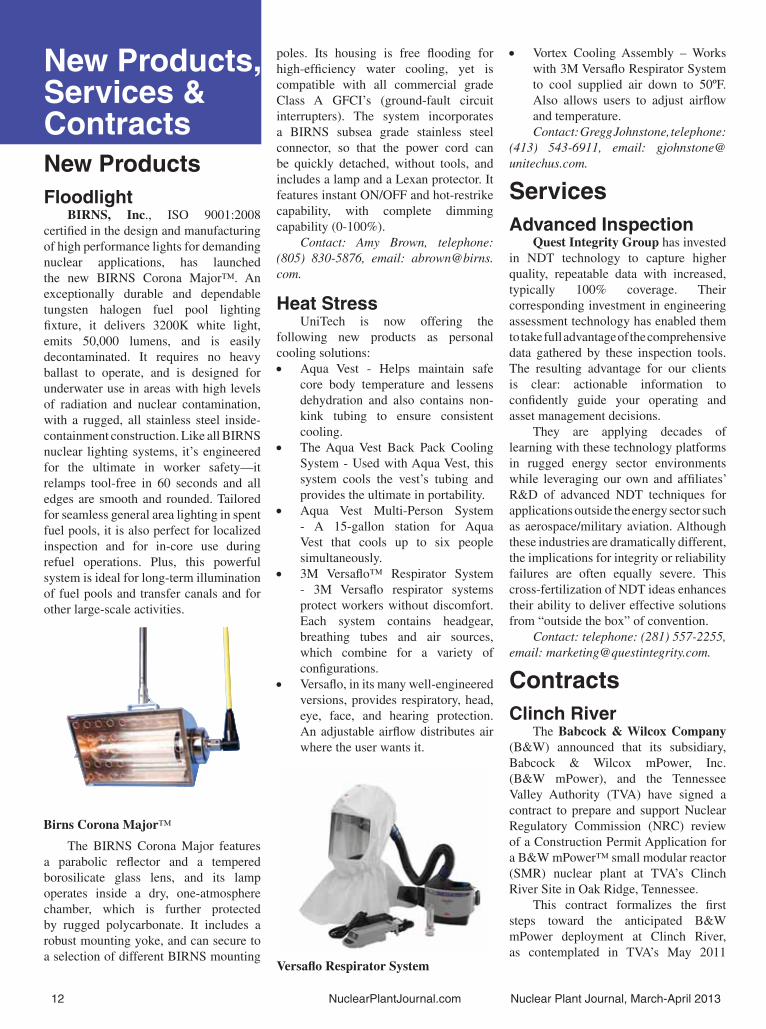
New Products, Services & ContractsNew ProductsFloodlight
BIRNS, Inc., ISO 9001:2008 certifi ed in the design and manufacturing of high performance lights for demanding nuclear applications, has launched the new BIRNS Corona Major™. An exceptionally durable and dependable tungsten halogen fuel pool lighting fi xture, it delivers 3200K white light, emits 50,000 lumens, and is easily decontaminated. It requires no heavy ballast to operate, and is designed for underwater use in areas with high levels of radiation and nuclear contamination, with a rugged, all stainless steel inside-containment construction. Like all BIRNS nuclear lighting systems, it’s engineered for the ultimate in worker safety—it relamps tool-free in 60 seconds and all edges are smooth and rounded. Tailored for seamless general area lighting in spent fuel pools, it is also perfect for localized inspection and for in-core use during refuel operations. Plus, this powerful system is ideal for long-term illumination of fuel pools and transfer canals and for other large-scale activities.
The BIRNS Corona Major features a parabolic refl ector and a tempered borosilicate glass lens, and its lamp operates inside a dry, one-atmosphere chamber, which is further protected by rugged polycarbonate. It includes a robust mounting yoke, and can secure to a selection of different BIRNS mounting
poles. Its housing is free fl ooding for high-effi ciency water cooling, yet is compatible with all commercial grade Class A GFCI’s (ground-fault circuit interrupters). The system incorporates a BIRNS subsea grade stainless steel connector, so that the power cord can be quickly detached, without tools, and includes a lamp and a Lexan protector. It features instant ON/OFF and hot-restrike capability, with complete dimming capability (0-100%).
Contact: Amy Brown, telephone: (805) 830-5876, email: [email protected].
Heat StressUniTech is now offering the
following new products as personal cooling solutions:
Aqua Vest - Helps maintain safe • core body temperature and lessens dehydration and also contains non-kink tubing to ensure consistent cooling.The Aqua Vest Back Pack Cooling • System - Used with Aqua Vest, this system cools the vest’s tubing and provides the ultimate in portability.Aqua Vest Multi-Person System • - A 15-gallon station for Aqua Vest that cools up to six people simultaneously.3M Versafl o™ Respirator System • - 3M Versafl o respirator systems protect workers without discomfort. Each system contains headgear, breathing tubes and air sources, which combine for a variety of confi gurations.Versafl o, in its many well-engineered • versions, provides respiratory, head, eye, face, and hearing protection. An adjustable airfl ow distributes air where the user wants it.
Vortex Cooling Assembly – Works • with 3M Versafl o Respirator System to cool supplied air down to 50ºF. Also allows users to adjust airfl ow and temperature.Contact: Gregg Johnstone, telephone:
(413) 543-6911, email: [email protected].
ServicesAdvanced Inspection
Quest Integrity Group has invested in NDT technology to capture higher quality, repeatable data with increased, typically 100% coverage. Their corresponding investment in engineering assessment technology has enabled them to take full advantage of the comprehensive data gathered by these inspection tools. The resulting advantage for our clients is clear: actionable information to confi dently guide your operating and asset management decisions.
They are applying decades of learning with these technology platforms in rugged energy sector environments while leveraging our own and affi liates’ R&D of advanced NDT techniques for applications outside the energy sector such as aerospace/military aviation. Although these industries are dramatically different, the implications for integrity or reliability failures are often equally severe. This cross-fertilization of NDT ideas enhances their ability to deliver effective solutions from “outside the box” of convention.
Contact: telephone: (281) 557-2255, email: [email protected].
ContractsClinch River
The Babcock & Wilcox Company (B&W) announced that its subsidiary, Babcock & Wilcox mPower, Inc. (B&W mPower), and the Tennessee Valley Authority (TVA) have signed a contract to prepare and support Nuclear Regulatory Commission (NRC) review of a Construction Permit Application for a B&W mPower™ small modular reactor (SMR) nuclear plant at TVA’s Clinch River Site in Oak Ridge, Tennessee.
This contract formalizes the fi rst steps toward the anticipated B&W mPower deployment at Clinch River, as contemplated in TVA’s May 2011
Birns Corona Major™
Versafl o Respirator System

Nuclear Plant Journal, March-April 2013 NuclearPlantJournal.com 13
Letter of Intent to B&W for the project. It also represents the fi rst defi nitive milestone in the U.S. Department of Energy’s (DOE) recently initiated SMR Licensing Technical Support Program for commercial demonstration of SMRs by 2022. The DOE selected B&W mPower in November 2012 as the recipient of the Program’s competitively bid cost-share funding grant.
Work at the Clinch River site will commence once B&W mPower and the DOE sign a cooperative agreement for the grant funds. The contract defi nes the respective responsibilities and work scopes for TVA and B&W to conduct the Clinch River Site geological characterization, develop a Preliminary Safety Analysis Report, and prepare an Environmental Assessment for deploying up to four mPower SMR reactors. TVA currently expects to submit the Construction Permit Application to the NRC in 2015.
Contact: Ryan Cornell, telephone: (330) 860-1345, email: [email protected].
Firewater PumpsClydeUnion Pumps, an SPX Brand,
received a contract to supply a specialised fi re protection pump for the Iberdrola S.A. Cofrentes nuclear power plant in Spain. The order for the seismic fi re protection pump was awarded to SPX in December 2012 by the plant operator Iberdrola S.A. with a scheduled delivery in March 2014.
The CUP-VS1 vertical multi-stage pump run by diesel motor, will be manufactured out of the 20,500 sqm SPX facility in Annecy, France. The pump will be designed according to ASME VIII and NFPA 20 standard for the installation of pumps for fi re protection. In addition, the pump will be IEEE seismic qualifi cation compliant. SPX’s pumping technology for fi refi ghting applications ensures that the pump operates effectively and remains functional when subjected to seismic disturbances.
The nuclear power plant, located near Valencia in Spain, is undergoing a global improvement project according to a new Spanish regulation for seismic fi re protection systems in nuclear plants.
Contact: Gillian Aird, telephone: 44 141 308 2247, email: [email protected].
Replacement FuelWestinghouse Electric Company
has been selected by Vattenfall Nuclear Fuels AB in Sweden to provide replacement fuel deliveries for the Forsmark 1 and Ringhals 3 nuclear power plants in 2015 and with an option for additional deliveries in 2016.
Under terms of the contract executed with Westinghouse Electric Sweden AB, Westinghouse will produce the fuel at its fabrication facility in Västerås, Sweden. Westinghouse has been one of the main suppliers of fuel to the Forsmark and Ringhals nuclear power plants since 1973. Since then, Westinghouse has delivered about 11,500 fuel assemblies to the plants. Only just recently, Westinghouse was awarded replacement fuel contracts for Forsmark Units 1 and 2 and Ringhals Units 2, 3 and 4 nuclear power plants in 2009 for the period 2011 to 2014.
Westinghouse Nuclear Fuel is a single-source fuel provider for pressurized water reactors (PWRs), boiling water reactors (BWRs) and advanced gas-cooled reactors (AGRs) worldwide. Westinghouse Nuclear Fuel has 10 manufacturing locations around the world, including two manufacturing sites in Europe: Springfi elds Fuels Limited (Preston, Lancashire, U.K.) and Westinghouse Electric Sweden (Västerås, Sweden). Westinghouse is currently fueling 153 PWR/BWR plants worldwide.
Contact: Scott Shaw, telephone: (412) 374-6737, email: [email protected]. �
www.NuclearPlantJournal.com
WHEN IT MATTERS MOST. . .
WHEN IT MATTERS MOST. . .
Who would you want to be tied to?
HukariAscendent
303-384-9079 www.hukari.com
HukariAscendent is a Service-Disabled Veteran-Owned
Small BusinessPlease email your resume to: [email protected]
In addition, please submit the on-line application at: w w w. h u k a r i . c o m

14 NuclearPlantJournal.com Nuclear Plant Journal, March-April 2013
New Documents
EPRI1. Nuclear Maintenance Applications Center: Main Feedwater Pump Maintenance Guide. Product ID: 1026476. Published November, 2012.
Loss of a main feedwater pump can have severe economic impact on a nuclear utility. The majority of forced outages or power reductions are believed to be attributed to nondesign issues. Case leaks, excessive vibration, seal leaks, and lubrication system problems are shown to signifi cantly impact feedwater pump availability. Improved maintenance practices and increased attention to these issues are critical for realizing longevity of main feedwater pumps.
2. Plant Engineering: EPRI Standardized Task Evaluation Program Implementation Guide. Product ID: 1025244. Published November, 2012.
The nuclear power industry uses supplemental workers to support outages and other work activities. It is important to provide assurances that these workers are knowledgeable and skilled in the performance of the specifi c tasks to which they will be assigned as independent workers. The end result must be objective, credible evidence to show that the independent workers have been evaluated to meet station standards. One method of determining whether a worker is profi cient is by using the Standardized Task Evaluation process. This report provides guidance and detail in the implementation of this program for organizations operating under accredited programs. The goal is to provide a work-ready work force without redundant, repetitive training and testing. Substantial cost savings could result from the sharing of industry personnel resources.
3. Steam Generator Management Program: Assessment of the Effect of Deposit Removal Frequency on Sludge Management. Product ID: 1025127. Published December, 2012.
In a PWR steam generator, the buildup of deposits on the tubes near the tubesheet
can increase the risk of tube degradation. To ensure the integrity of the tubes which are part of the primary-to-secondary side pressure boundary, various repair and mitigation techniques are available which have attendant benefi ts, risks, and costs. To mitigate deposit buildup, utilities employ a variety of deposit removal techniques, such as sludge lancing and chemical cleaning. This report addresses the effect of sludge lancing frequency on sludge management.
4. Validation of Stress Corrosion Cracking Initiation Model for Stainless Steel and Nickel Alloys. Product ID: 1025121. Published December, 2012.
An EPRI model to evaluate the stress corrosion cracking (SCC) initiation, including initial short crack growth and the effects of cold work (CW) on SCC susceptibility, has been successfully validated. This SCC initiation model was developed in earlier EPRI projects for Ni-base alloys and austenitic stainless steel in high-temperature water. The validation has involved use of independent data sets for as-received and cold-worked material conditions as well as an alternate method of estimating SCC initiation life, also based on an independent source of data not used in development of the SCC initiation model.
5. Welding and Repair Technology Center: Assessment of Friction Stir Welding for Nuclear Applications. Product ID: 1025175. Published December, 2012.
This report describes a study that was conducted to determine the usability of friction stir welding (FSW) for the repair of nuclear power plant components. The fi rst phase of the study has performances in air and underwater welding on 304 SS, 308L SS, Alloy182, and Alloy 600 test plates. In addition, crack sealing tests were carried out using electric discharge machining notches in these test plates. A patch seal test was also added to the
test matrix to determine if a fl at plate could be successfully bonded in air and underwater. The patch test was performed on Type 304 SS.
The second phase of the project will complete an in-depth metallurgical examination of all tests conducted during Phase 1. The third phase of the project will be to design a prototype concept for an underwater FSW tool to make repairs to the shroud in a boiling water reactor (BWR) and optimize the tool design for underwater applications.
6. Plant Engineering: Users Guide for the Development of Life Cycle Management Plans. Product ID: 1025260. Published December, 2012.
This guide provides direction for the user in the development, implementation, and maintenance of life cycle management plans (LCMPs). The guide includes an appendix containing a template that users can employ in the development of their plant-specifi c LCMPs.
7. Nuclear Maintenance Application Center Memo, Fall 2012. Product ID: 1026814. Published December, 2012.
The NMAC Memo is an on-line newsletter that may be accessed using the link: http://mydocs.epri.com/docs/corporatedocuments/newsletters/nmac/winter-2012/Memo.html
EPRI’s Nuclear Maintenance Applications Center (NMAC) serves as an international forum delivering proven, practical techniques and methods to successfully improve member’s plant maintenance activities. The NMAC Memo is published three times a year and covers recent, ongoing, and upcoming NMAC activities and accomplishments.
The above EPRI documents may be ordered by contacting the Order Center at (800) 313-3774 Option 2 or email at [email protected]. �

16 NuclearPlantJournal.com Nuclear Plant Journal, March-April 2013
Research & Development
Inspection of Concrete Structures
EPRI is pursuing the development and demonstration of a robotic nondestructive evaluation tool that would facilitate the safe inspection of concrete structures at nuclear power plants.
The energy industry contains a number of large, curved vertical structures where structural inspection is required, including cooling towers, nuclear containments and hydroelectric dams. Inspecting these structures typically requires several people and the use of extensive scaffolding. Automating such inspections would increase safety and reduce inspection time and costs.
To identify candidate automated robotic technologies, EPRI conducted a wide-ranging review of available technologies, their readiness levels, and whether they could be adapted to the electricity sector. Through this search, EPRI came across a “concrete crawler” device that can crawl up curved, vertical concrete structures carrying a payload of about 20 kilograms. This crawler also can navigate gaps, seams and obstacles that may be encountered on the concrete surface, such as conduit.
EPRI evaluated various mapping and positioning systems for this application and selected the Simultaneous Mapping and Location System code developed by the Technical University of Darmstadt in Germany, which could be confi gured to the crawler. Likewise, an NDE device capable of collecting information by means of air coupling was identifi ed and mounted on the crawler.
A demonstration during the Fall 2012 confi rmed the individual capabilities of the subsystems, and EPRI is now pursuing integration of the crawler, positioning system and NDE device. The fi rst fi eld demonstration of the integrated device will be at a hydroelectric dam in 2013. The lessons learned from this application are expected to be readily transferred
to nuclear containments and cooling towers.
Contact: Maria Guimaraes, telephone: (704) 595-2708, email: [email protected].
Aging Management Programs
To support decisions regarding long-term operations, EPRI is reviewing the technical basis underlying plant aging management programs to determine if changes are needed to address identifi ed technical gaps.
Assessing the viability of safe, reliable plant operations over extended time periods requires an understanding of the technical basis supporting such long-term operations (LTO). In the United States, the Nuclear Regulatory Commission has gradually formalized the evaluation of aging management programs as a key attribute of the license renewal process; in other countries, similar mechanisms are in place or under development. Through its LTO Program, EPRI is reviewing the technical bases underlying aging management programs for nuclear structures, systems and components (SSCs) to confi rm that the bases support extended operations or to identify R&D gaps. An ongoing project aims to develop a technical basis document that:
Identifi es likely enhancements and • gaps in current aging management programs and highlights gaps that need to be fi lled to address technical issues for safe long-term operationsSupports plans for incorporating • research results and operating experience into aging management programs.Can be maintained as a tracking tool • to ensure all signifi cant research gaps are addressed in an adequate time frame to support LTO.To date, this project has completed
initial assessments of R&D needs for aging management programs related to operation beyond 60 years. These assessments are now undergoing
peer review and refi nement, and will provide a critical link between the aging degradation knowledge base and a plant’s aging management actions, such as periodic inspections, operating parameter monitoring and control, and periodic tests. For example, the EPRI Coordinated Surveillance Capsule Program will provide reactor pressure vessel embrittlement data at neutron fl uence levels beyond those expected at 60 years of operation. This data will then serve as a basis for inspection and monitoring actions under a corresponding reactor pressure vessel aging management program for operation beyond 60 years. Similarly, an EPRI project to develop a fi rst-of-a-kind containment assessment guideline (to be published in 2013) will inform utility decisions on aging management actions for containment.
Contact: Rich Tilley, telephone: (704) 595-2597, email: [email protected].
Non-Contacting Laser Scanner
Development, demonstration and deployment of this technology could reduce or eliminate problems caused by fuel distortion, such as the inability to insert control blades.
The distortion of fuel assemblies and channels due to in-reactor irradiation can signifi cantly impact both boiling and pressurized water reactors. The distortion can result in axial, lateral and torsional displacements that affect the ability to insert control rods or blades during plant operations and that negatively impact fuel handling during outage activities. Accurate quantifi cation of this distortion is necessary so that mitigating strategies can be implemented to limit or eliminate these impacts.
EPRI is investigating the feasibility of non-contacting technologies using an array of lasers and optical cameras to potentially improve distortion measurements. The challenge is to make these measurements such that outage
Nuclear Plant Journal, March-April 2013 NuclearPlantJournal.com 17
critical path is not compromised. Current methods involve physical contact with the fuel assemblies and channels, and only produce spatially coarse measurements. Newer non-contacting tools can improve the effi ciency and accuracy of these measurements.
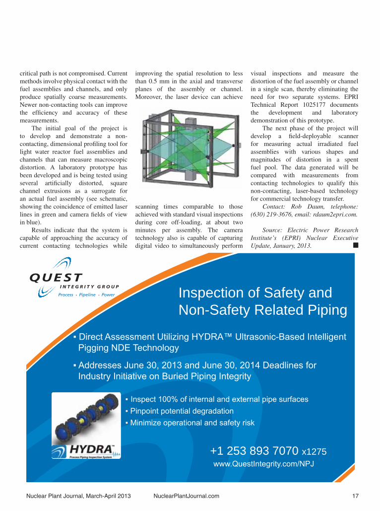
The initial goal of the project is to develop and demonstrate a non-contacting, dimensional profi ling tool for light water reactor fuel assemblies and channels that can measure macroscopic distortion. A laboratory prototype has been developed and is being tested using several artifi cially distorted, square channel extrusions as a surrogate for an actual fuel assembly (see schematic, showing the coincidence of emitted laser lines in green and camera fi elds of view in blue).
Results indicate that the system is capable of approaching the accuracy of current contacting technologies while
improving the spatial resolution to less than 0.5 mm in the axial and transverse planes of the assembly or channel. Moreover, the laser device can achieve
scanning times comparable to those achieved with standard visual inspections during core off-loading, at about two minutes per assembly. The camera technology also is capable of capturing digital video to simultaneously perform
visual inspections and measure the distortion of the fuel assembly or channel in a single scan, thereby eliminating the need for two separate systems. EPRI Technical Report 1025177 documents the development and laboratory demonstration of this prototype.
The next phase of the project will develop a fi eld-deployable scanner for measuring actual irradiated fuel assemblies with various shapes and magnitudes of distortion in a spent fuel pool. The data generated will be compared with measurements from contacting technologies to qualify this non-contacting, laser-based technology for commercial technology transfer.
Contact: Rob Daum, telephone: (630) 219-3676, email: rdaum2epri.com.
Source: Electric Power Research Institute’s (EPRI) Nuclear Executive Update, January, 2013. �
Inspection of Safety and Non-Safety Related Piping
+1 253 893 7070 x1275

Sequoyah License Renewal By Tennessee Valley Authority.
Response to questions by Newal Agnihotri, Editor of Nuclear Plant Journal.
1. The $23 million expected cost as mentioned in your news release, is it just the license renewal application preparation cost for the US NRC or it is the complete cost, including the hardware prices for systems, equipment, and instruments, including design, labor, and material cost?
The $23 million expected cost in the news release includes the cost of developing the license renewal application, NRC review fees, performing required calculation updates, revising procedures and issuing work orders for inspections. The cost does not include the cost of required inspections or the hardware cost for plant modifi cations that may be necessary prior to or during the period of extended operation.
2. How are you assisting US NRC in their evaluation of the long-term environmental effects of storing of used nuclear fuel at nuclear plant sites?
The NRC is on a two-year schedule to address the Waste Confi dence Decision and Rule defi ciencies identifi ed by the 2012 court decision and has had several meetings to solicit public input. In addition, NRC is planning to issue draft reports for public comment. TVA has participated in the public meetings to date and will review NRC draft documents as they become available, providing comments as appropriate.
3. What are the proposed modifi cations of systems, equipment, and instruments as part of the plant license renewal?
No specifi c modifi cations are required to support plant license renewal. The license renewal process ensures that
programs are in place to manage the effects of aging through the period of extended operation. Modifi cations of plant systems, equipment and instruments are performed during the period of extended operation as determined necessary through the monitoring activities of the aging management programs.
4. What modifi cations required due to the US NRC’s Fukushima Near-Term Task Force are part of the current plant license renewal modifi cations?
Modifi cations required to support the US NRC’s Fukushima Near-Term Task Force are not a prerequisite or a requirement for plant license renewal. However, plant modifi cations that affect the plant design and licensing basis, including those implemented in response to the Fukushima Near-Term Task Force fi ndings, will be evaluated to ensure the affected equipment is included in the proper aging management programs.
5. What, if any, fuel upgrade is being undertaken during this license renewal?
No fuel upgrade is being undertaken as part of the Sequoyah license renewal project.
6. What PRA studies are parts of this license renewal process?
The existing Sequoyah Nuclear Power Plant (SQN) internal events PRA were updated to meet current regulatory standards. The updated PRA was then used to evaluate Severe Accident Mitigation Alternatives (SAMA) as part of the development of the SQN license renewal environmental report.
7. What non-NRC guidance such as NEI and other industry guidelines and standards are being relied upon for the plant license renewal?
NEI-95-10, “Industry Guideline for Implementing the Requirements of
10CFR Part 54 – The License Renewal Rule,” was used in the development of the Sequoyah License Renewal Application.
8. Are there any safety-related instrument upgrades to digital technology being undertaken as part of this extension?
No safety-related instrument upgrades to digital technology are being undertaken as part of Sequoyah license renewal.
9. What material degradation issues have been observed in the reactor coolant system in the past and what measures are being taken to ensure that these are managed during the renewed license term of the plant?
No material degradation in the reactor coolant system has been identifi ed that would require replacement of systems, structures or components for the extended life of the plant. Reactor coolant system aging management programs will manage the effects of aging on the system for the period of extended operation.
10. How is the water chemistry being controlled to ensure that the fl uid in the reactor coolant system is not aggressive on the equipment?
The SQN Chemistry Program monitors concentrations of corrosive impurities and maintains water quality in accordance with the Electric Power Research Institute (EPRI) primary water chemistry guidelines to ensure that the reactor coolant system fl uid is not aggressive to system components. The SQN Chemistry Program also maintains water quality of the secondary plant systems in accordance with EPRI guidelines.
Contact: Scott Brooks, telephone: (615) 232-6141, email: [email protected]. �
18 NuclearPlantJournal.com Nuclear Plant Journal, March-April 2013

D I E S E L G E N E R A T O R S E T SThe Proven Leader
www.fairbanksmorse.com
WE’LL KEEP THE LIGHTS ON FOR YOU

20 NuclearPlantJournal.com Nuclear Plant Journal, March-April 2013
Successes & Challenges of Extended Power UprateBy Dave Dellario, Phil Amway, and Kathy Picciott, Constellation Energy Nuclear Group.
Dave DellarioDave Dellario is currently the Manager – Engineering Services, overseeing Constellation Energy Nuclear Group’s (CENG) Fukushima response efforts. Dave joined CENG in 1991 as a system engineer and has served as Mechanical Engineering Supervisor, Director of the Calvert Cliffs Unit 2 Head Replacement Project, Director of Fleet Projects and Director of Project Management for the Nine Mile Point Unit 2 Extended Power Uprate Project at Nine Mile Point.
Phil AmwayPhil Amway is currently the Fleet Technical Lead for CENG’s Fukushima Project at Nine Mile Point Nuclear Station. He has 32 years of nuclear experience in the fi elds of Quality Assurance, Reactor Engineering and Operations. Phil joined CENG in 1991 as a licensed Senior Reactor Operator at Nine Mile Point Unit 2. Phil also served more than eight years in the U.S. Navy Nuclear Program as an operator and maintenance mechanic.
Kathy PicciottKathy Picciott is currently the Project Lead for CENG’s Fukushima Project at Nine Mile Point Nuclear Station and has more than 25 years experience in the nuclear industry. She started at Nine Mile Point in 1985 as a structural engineer. She also served in other engineering positions and then moved into project management progressing to General Supervisor. Picciott also held the position of Manager – Performance Improvement.
Response to questions by Newal Agnihotri, Editor of Nuclear Plant Journal.
1. What was the approximate cost for the plant’s power plant uprate?
Constellation Energy Nuclear Group invested nearly $250 million in the long-term reliability of Nine Mile Point Unit 2 and helping us meet the growing demand for additional clean air energy.
The cost breakdown is:Project Management, Site Labor, and • Oversight: $23,800,000.Engineering Services: $74,800,000.• Construction and Implementation: • $89,800,000.Licensing: $3,500,000.• Equipment and Materials: $43,600,000.• I&C and Instrumentation: $4,200,000.•
2. Provide an overview of the successes and challenges in accomplishing the extended power uprate.
Like any major project, there are numerous challenges and successes experienced along the way to implementation. Signifi cant successes include:
Restoration of full core fl ow • capability through replacement of jet pump inlet mixers. Senior managers maintained an operational focus by dedicating resources to ensure that the operators were not challenged by reduced core fl ow capabilities.Since Extended Power Uprate (EPU) • implementation, there have been no plant de-rates required as a result of the uprate.The power ascension test program • was completed safely and event-free, including numerous Infrequently Performed Tests and Evolutions (IPTEs).Better-than-expected electrical output • was achieved through replacement of the turbine high pressure rotor.Feed water minimum fl ow valve • radiography was completed safely and event free.The ratio of the cost of the EPU • compared to the increase in electrical output is low compared to the industry average of power uprates.
EPU Project Engineering was • responsible for technical support of the Licensing submittal and U.S. Nuclear Regulatory Commission (NRC) review process, design of over 50 permanent and temporary modifi cations, and execution of the power ascension test program.Some of these modifi cations were not • directly related to the implementation of the EPU project, but positively contribute to the long-term reliability of the station.Power ascension was implemented • successfully with no major challenges through the effective use of internal and external operating experience to identify best practices, including benchmarking other plants that completed (or were in the process of completing) similar EPU projects.
Our signifi cant challenges include:Material handling/lifting and rigging • events during the implementation outage resulted in challenges in safety performance on the job.Steam dryer modifi cations to support • the higher steam fl ows at EPU conditions; challenges in this area resulted in longer time durations for the modifi cations and increased dose to workers.
3. Were there any fuel upgrades or modifi cations done to accomplish the extended power uprate?
The same fuel design was used to implement the EPU. To achieve the higher power level, a higher batch fraction of new fuel assemblies were needed with average enrichment remaining approximately the same as pre-uprate conditions.
4. What instrumentation modifi cations, including converting analog to digital, were accomplished during the recent extended power uprate?
Numerous changes to power conversion system instrumentation were required to implement the EPU. These changes were primarily rescaling or

Nuclear Plant Journal, March-April 2013 NuclearPlantJournal.com 21
replacement to accommodate the higher fl ow rates, temperatures and pressures associated with uprate conditions. There
were no analog to digital conversions performed as part of the power uprate project.
5. What upgrade of the turbine, generator, Transformers, and isolated phase bus were accomplished for the power uprate?
Upgrades to power conversion systems included replacement of the high pressure turbine rotor, higher capacity cooling systems for the main transformers and replacement of the isolated phase bus duct cooling system with a system of higher heat removal capacity.
6. Share any experiences that the power plant had in public relations to achieve licensing of the extended power uprate.
Nine Mile Point Nuclear Station maintains good community relations with the surrounding communities. There were no public relations challenges to the EPU licensing process.
Contact: Nine Mile Point Nuclear Station, c/o Communications, P.O. Box 63, Lycoming, New York 13093. �
For Equipment Productivity and Durability You Can Trust Choose Wachs for Your Pipe Cutting & Beveling Needs We pride ourselves in building customer relationships
Call us for more information on YOUR specific APPLICATION and we can recommend the right equipment for your needs. Because at E. H. Wachs, you will always get Superior Equipment. Complete Support.
Cut and J-Prep Heavy wall single point application
eeds For rent or purchase.
Call to schedule a demo or request a quote.
Wachs’ Pipe Cutting and Beveling Tools Are:
• Built to maximize your profit with the lowest cost per cut• Engineered to withstand rigorous environments• Field tested for optimum performance• Manufactured for long wear life
Wachs offers a full line of pipe maintenance equipment ideal for your specific application. Features that all of Wachs equipment include:
• Efficient cold cutting technologies for precise and accurate weld preps • Simultaneous cutting and beveling
Onsite, portable machine tools for pipe maintenance and repair that perform:
• Cutting • J-Preps • Beveling • Flange Facing• Counterboring
• Lightweight, yet durable• Easy set-up and operation
Call today: 800-323-8185Visit us @ ehwachs.com
Nine Mile Point Nuclear Station.
Peach Bottom’s 12.4% EPUBy Michael Massaro, Exelon Generation.
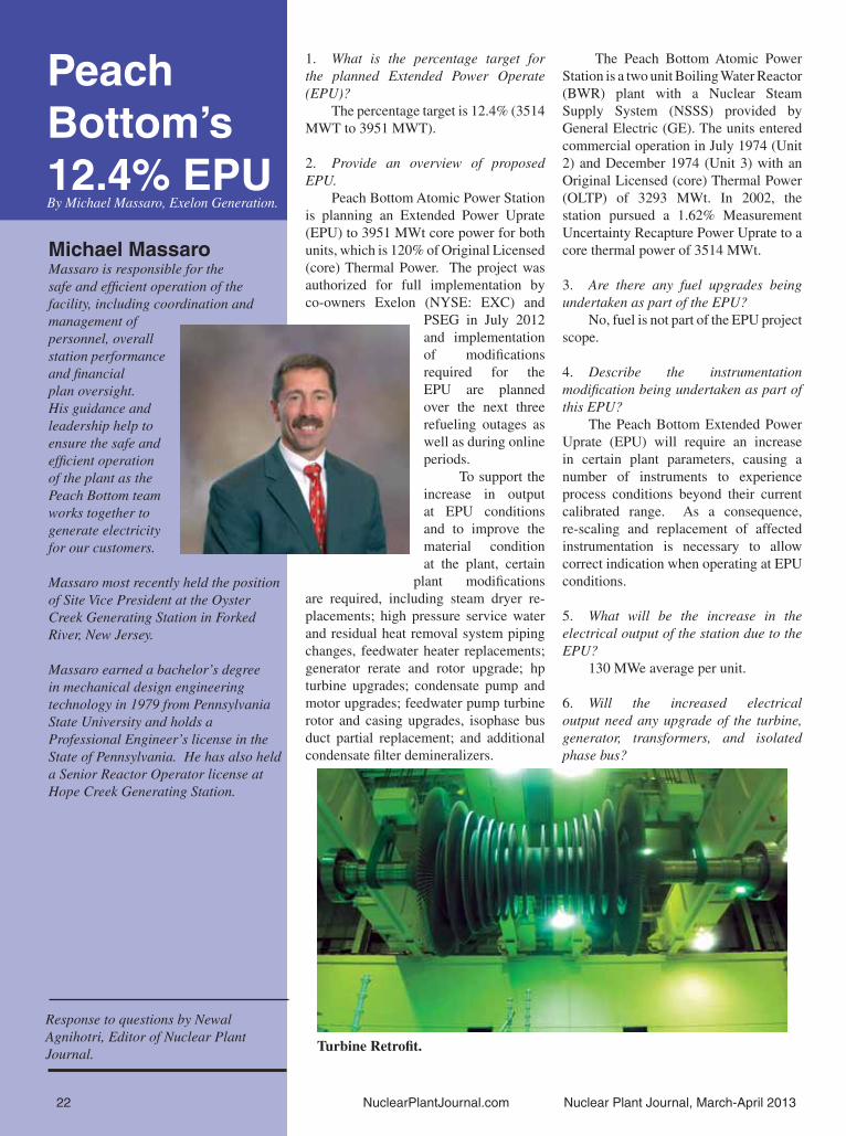
Michael MassaroMassaro is responsible for the safe and effi cient operation of the facility, including coordination and management of personnel, overall station performance and fi nancial plan oversight. His guidance and leadership help to ensure the safe and effi cient operation of the plant as the Peach Bottom team works together to generate electricity for our customers.
Massaro most recently held the position of Site Vice President at the Oyster Creek Generating Station in Forked River, New Jersey.
Massaro earned a bachelor’s degree in mechanical design engineering technology in 1979 from Pennsylvania State University and holds a Professional Engineer’s license in the State of Pennsylvania. He has also held a Senior Reactor Operator license at Hope Creek Generating Station.
Response to questions by Newal Agnihotri, Editor of Nuclear Plant Journal.
1. What is the percentage target for the planned Extended Power Operate (EPU)?
The percentage target is 12.4% (3514 MWT to 3951 MWT).
2. Provide an overview of proposed EPU.
Peach Bottom Atomic Power Station is planning an Extended Power Uprate (EPU) to 3951 MWt core power for both units, which is 120% of Original Licensed (core) Thermal Power. The project was authorized for full implementation by co-owners Exelon (NYSE: EXC) and
PSEG in July 2012 and implementation of modifi cations required for the EPU are planned over the next three refueling outages as well as during online periods.
To support the increase in output at EPU conditions and to improve the material condition at the plant, certain
plant modifi cations are required, including steam dryer re-placements; high pressure service water and residual heat removal system piping changes, feedwater heater replacements; generator rerate and rotor upgrade; hp turbine upgrades; condensate pump and motor upgrades; feedwater pump turbine rotor and casing upgrades, isophase bus duct partial replacement; and additional condensate fi lter demineralizers.
The Peach Bottom Atomic Power Station is a two unit Boiling Water Reactor (BWR) plant with a Nuclear Steam Supply System (NSSS) provided by General Electric (GE). The units entered commercial operation in July 1974 (Unit 2) and December 1974 (Unit 3) with an Original Licensed (core) Thermal Power (OLTP) of 3293 MWt. In 2002, the station pursued a 1.62% Measurement Uncertainty Recapture Power Uprate to a core thermal power of 3514 MWt.
3. Are there any fuel upgrades being undertaken as part of the EPU?
No, fuel is not part of the EPU project scope.
4. Describe the instrumentation modifi cation being undertaken as part of this EPU?
The Peach Bottom Extended Power Uprate (EPU) will require an increase in certain plant parameters, causing a number of instruments to experience process conditions beyond their current calibrated range. As a consequence, re-scaling and replacement of affected instrumentation is necessary to allow correct indication when operating at EPU conditions.
5. What will be the increase in the electrical output of the station due to the EPU?
130 MWe average per unit.
6. Will the increased electrical output need any upgrade of the turbine, generator, transformers, and isolated phase bus?
Turbine Retrofi t.
22 NuclearPlantJournal.com Nuclear Plant Journal, March-April 2013

Nuclear Plant Journal, March-April 2013 NuclearPlantJournal.com 23
Yes. The low pressure turbines, main power transformers and the generator stator have already been upgraded. The generator rotor and isolated phase bus upgrades are planned for EPU.
7. Are there any US NRC’s Fukushima Near Term Task Force recommendations being incorporated as part of the EPU project?
The US NRC’s Fukushima Near Term Task Force recommendations are not part of the EPU project scope and are being addressed as a separate station project.
8. What preparations have been made to gain the support of the public for the EPU during the public hearing process?
The EPU project has been a key component of stakeholder and media outreach over the past several years as part of the delivery and installation of several signifi cant equipment investments, including turbines and transformers.
Last year, approximately 500 residents attended the station’s annual Community Information Night, which is an opportunity for them to tour the simulator, meet station leadership and learn more about recent or upcoming projects, most of which are related to EPU.
Additionally, the station hosts a “State of the Plant” dinner for local elected offi cials, emergency management professionals and other local stakeholders to discuss a variety of topics, including EPU.
Local media enjoy a close relationship with station leadership. Over the past several years, the site has hosted numerous media tours focused on EPU projects.
Contact: Lacey Dean, Peach Bottom Atomic Power Station, 1848 Lay Road, Delta, Pennsylvania; telephone: (717) 456-4818. �
Transformer Replacement.
January-FebruaryInternational Trade & Waste & Fuel Management
March-AprilPlant Maintenance & Plant Life Extension
May-JuneOutage Mgmt. & Health Physics
July-AugustNew Plants & Vendor Advertorial
September-OctoberPlant Maintenance & Advanced Reactors
November-December Annual Product & Service Directory
Contact: [email protected]: (630) 364-4780
AnnualEditorial
Schedule

(Continued on page 26)
A Safe Plant for the 21st CenturyBy Anthony Robinson, AREVA Inc.
Anthony RobinsonMr. Robinson holds the position of Vice President, for the North American New Builds business group of AREVA NP.
Located in Lynchburg, Virginia, Mr. Robinson oversees and manages the organizations responsible for all aspects of the nuclear new plant deployment activities in the U.S. and Canada.
Mr. Robinson has over 25 years of combined leadership experience in the nuclear and telecommunication industries. Prior to his tenure with the New Builds organization, he was Director of Project Management for AREVA Inc.
Mr. Robinson holds a degree in Mechanical Engineering from the University of Akron, attended theExecutive MBA program at Kent State University, and is a registered Professional Engineer in the Stateof Ohio.
Response to questions by Newal Agnihotri, Editor of Nuclear Plant Journal.
1. What is the current licensed life of EPR in the United States and in China?
The duration of the operating license is governed by the regulations of the country in which the plant is located. In the United States, the license is for 40 years and may be extended in 20-year increments. In France and China, the licensees update the safety case every 10 years and submit a license amendment application for regulatory approval.
2. What is the design life of the EPR?The design life of the EPRTM is 60
years. All structures and large mechani-cal components are designed for 60 years. Other equipment has a design life
of 60 years unless it is impractical such as 1) parts that are replaced or refur-bished during normal plant maintenance, 2) equipment that cannot be procured from suppliers at this design life (e.g., large motors, trans-formers, switchgear or internals of ro-tating machinery such as pump shafts, pump impellers, tur-bine shafts, turbine blades, fans, etc….as manufacturers do
not offer 60-year design life for these components), and 3) equipment that be-comes obsolete due to rapid technology development (e.g., digital instrumenta-tion and controls). Regardless of design life, with the exceptions of the reactor vessel and turbine casings, all equipment in the EPRTM is designed to be removed and replaced without the deconstruction or demolition of any structures, using pre-engineered lifting devices and haul routes designed for the task.
3. What modifi cations in design, structures, systems, equipment, and instruments have been made to support a plant life higher than 40 years?
Most operating plants have shown signifi cant margins built into the design such that extending the design life
from 40 years to 60 years was possible without signifi cant plant modifi cations or equipment replacements. AREVA simply incorporated those design requirements into the EPRTM from the beginning, including suffi cient heat-up/cooldown cycles, maneuvering cycles and erosion/corrosion allowances to bound 60 years of operation. The largest contributors to fatigue of major components (what some would call “wear and tear”) are the stress caused by thermal expansion or contraction caused by heating the plant from cold to hot full power conditions or from cooling the plant from hot conditions to room temperature. The effect is similar to bending a piece of foil in your hands forward and backward. Eventually, after a large number of bendings (e.g. cycles) the foil will break. Big equipment must be designed for a number of loading and unloading cycles so as to bound operation for 60 years with a very wide design margin. Furthermore, certain operating conditions and plant maneuvers were modifi ed to reduce fatigue on critical components. Materials were selected based on proven reliability over four decades of operation in the light water reactor fl eet. Just as signifi cant, many EPRTM components were designed by analysis rather than code equations, which increases operating margin by reducing unnecessary conservatism in the design. INPO AP-9131 is integrated into the detailed design, procurement and construction processes to further enhance equipment reliability. Equipment diagnostics and on-line monitoring systems provide additional confi dence in the equipment as the plant ages.
4. Are there any plans, built-in EPR to enable its 80-year life?
AREVA is confi dent that signifi cant conservatism is built into the design such that after 60 years of operation there will be suffi cient design margin available to accommodate an additional 20 years of operation. On-line fatigue monitoring, transient assessments and in-service inspections will validate the condition of the plant to operate beyond the design life.
1. INPO- AP 913 “Equipment Reliability Process Description” November 2001.
24 NuclearPlantJournal.com Nuclear Plant Journal, March-April 2013

801 South Illinois Ave., Oak Ridge, TN 37831-0895 U.S.A. • (865) 482-4411 • Fax (865) 483-0396 • [email protected] International Office Locations, Visit Our Website
ORTEC www.ortec-online.com®
The next generation fully integrated High-Purity Germaniumdigital spectroscopy system that eliminates liquid nitrogenand is immune to thermal cycling.
The Laboratory Detector Module LDM-1 is ahighly sensitive all-in-one HPGe gamma-ray spectrometerfor use in a variety of applications ranging from countinglabs to mobile laboratories.
• Increases productivity and instrument uptime due to the fact that thermal cycling is never required on a partial warm up. TheHPGe detector element is encapsulated in a metal sealed high reliability cryostat that does not contain molecular sieve.
• Reduces cost and improves safety since liquid nitrogen is not required. The Stirling-cycle cooler keeps the detector at a stablecryogenic temperature.
• Space saving integrated design eliminates desk mounted hardware and excessive cabling that frees up additional lab space.
• Eases installation due to lightweight design of only 7.3 kg. The LDM-1 is ideal for confined spaces and mobile labs. It easily fits intoexisting standard lead shields and only requires a single USB cable to connect to the computer.
• Low power consumption reduces operating costs. The LDM-1 is powered from a small 10–17 V DC supply that consumes lessthan 30 watts. This also makes mobile installations simple.
• Continuous operation via redundant power options. The LDM-1 comes standard with an integrated battery that keeps the entiresystem operating and counting for up to 4 hours. Additionally, with the optional battery extender LDM-1-OPT-1, the systemcontinues operating for 18 hours. The battery extender is also hot swappable so the system never stops counting.
For more information, visit: www.ortec-online.com/download/LDM-1.pdf

26 NuclearPlantJournal.com Nuclear Plant Journal, March-April 2013
A Safe Plant...Continued from page 24
5. What monitoring systems have been provided in EPR to monitor and detect degradation of a structures, systems, equipment, and instruments to ensure an early warning of an incipient failure?
AREVA has several monitoring systems that automatically collect operating data on plant systems, structures and components, and make it available to multiple diagnostic programs. This not only provides early warning of problems, but EPRTM owners can share real-time or historical data and remotely access expertise at other EPRTM units or at the original equipment manufacturer. This approach allows fl eet-wide solutions and signifi cant reductions in operating staff required at each site normally used to assess the data.
Some of the technologies employed at EPRTM plants currently under construction in Finland, France and China include:
Loose parts monitoring• Vibration monitoring for stationary • equipmentSeismic monitoring• Fatigue monitoring• Leakage monitoring• Diagnostics of rotating machinery• Diagnostics of valves and actuators• Flow-assisted corrosion monitoring• Plant transient, performance and • condition assessmentContainment tendon load measure-• mentsContainment displacement measure-• ments
6. What are the features of the EPR control room to make it user friendly to the younger generation who are more IT and Internet savvy?
The controls of the EPRTM are based on proven experience at the French N4 and German KONVOI facilities. The man-machine interface is a cornerstone of the highly automated EPRTM control
system. Any of today’s computer savvy generation will feel right at home working the EPRTM digital control systems, with fl at panel displays and point-and-click technology. In addition to wide displays at individual workstations, large heads-up panels provide indications of plant conditions. Standard screens are pre-programmed to rapidly display important equipment and operating parameters, but some leeway is allowed for operators to program user-specifi ed displays.
Of course, the control room layout and user interfaces are developed from a Human Factors Engineering (HFE) Program that conforms to the requirements and the structure of NUREG-0711, Revision 22, in which the HFE team is integrated with the instrumentation and control design team. The “older generation” will recognize conventional control panels with push buttons and toggle switches to monitor, and if necessary, actuate safety-related functions in case of a plant event with loss of the digital controls.
7. What margins are built in the design of the turbine, condensate pumps, motors, generators and transformers to accommodate extended power uprate or other type of power uprates in the future?
With a net electrical output of 1600 MWe, the EPRTM is designed to deliver maximum power for an economical price. Although the nuclear steam supply system
design can be uprated approximately fi ve percent, AREVA reserves this design margin for fl exible operations and to accommodate future regulatory or emerging issues. “Flexible operations” refers to non-traditional operation of the plant. Current units run base-loaded (i.e., at full power conditions continuously). In the future, load following or extended operations at less than 100% power may be required depending upon the energy mix. Over-sizing the secondary plant for a future power uprate that may never be pursued must be balanced with the associated increase in levelized cost of electricity prior to uprate. “Secondary plant” is industry shorthand for the conventional, non-nuclear island; this part of a power plant typically includes the turbine, condensate, feedwater, main generator, electrical distribution system, and other common systems. AREVA Inc. has adopted such a balanced approach. For those items that are intended to have a service life of 60-plus years, margins for future uprating are included in the initial design. Those components that are relatively straightforward to upgrade are designed to accommodate the licensed power level.
8. What post Fukushima upgrades have been made to the EPR in response to US NRC’s Near Term Task Force Recommendations?
The EPRTM is designed for an event just like the Fukushima earthquake and tsunami. Four redundant, seismically qualifi ed emergency generators would provide power to critical equipment required to shutdown and cool the reactor. The plant would be situated above the highest elevation attainable by fl ood or tsunami, and power supplies and critical equipment are in watertight buildings. Fuel supplies and electrical connections for these emergency generators would also be in seismically qualifi ed, watertight buildings. Cooling water for the emergency generators and other critical equipment, including core cooling equipment, would be in earthquake proof buildings completely
2. J.M. O’Hara, J.C. Higgins, J.J. Persensky, P.M. Lewis, J.P. Bongarra, NUREG-0711, Human Factors Engineering Program Review Model, Revision 2, February 2004 (available on nrc.gov).
Taishan 1 EPR Reactor Construction Site, China. November 9, 2012. Copyright: AREVA, TNPJVC.

Nuclear Plant Journal, March-April 2013 NuclearPlantJournal.com 27
protected from tornado missiles or other debris. Consequently, the U.S. EPRTM plant would have suffi cient on-site resources to shutdown and cool the core for more than two weeks without any outside assistance.
The U.S. EPR emergency power and cooling systems are already designed to address “beyond design basis events”. The Near Term Task Force (NTTF) recommendations do not account for plants with increased levels of safety and redundancy in emergency cooling supplies. As a result, to make the U.S. EPR design even safer, AREVA made some additions to the design to address the NTTF recommendations. The NTTF focused on operating plants that typically have two seismically qualifi ed emergency diesel generators that are augmented by an alternate A/C power source to accommodate the Station Blackout Rule. So, the NTTF applied an Extended Loss of A/C Power event to be addressed by these units. The U.S. EPRTM goes beyond this approach by incorporating four emergency diesels that are in seismically qualifi ed structures that are also located above the fl oodplain and are leak tight. Fuel and cooling sources are likewise protected from any harm and electrical connections, air intakes and air exhausts are located more than 60-feet above grade, making them impervious to fl ooding.
Adequate core cooling can easily be maintained for 24 hours after a loss of offsite power, even with no credit for installed emergency or station blackout diesel generators, by shedding unnecessary loads from the station batteries and the use of a hard piping connection between the fi rewater system and the secondary coolant loop. Long-term cooling in accordance with the task force recommendations can be provided via connections from fi rewater or portable pumps to allow cooling water to be delivered to both the secondary coolant loop and the primary circuit (direct core cooling).
9. What fuel design, fuel monitoring, and fuel storage enhancements have been made in EPR?
To provide the most reliable fuel performance possible, AREVA based the EPRTM fuel design on existing AREVA products with long performance histories. We retained our advanced M5TM cladding that is extremely resistant to oxidation, and assembled the fuel pins in our robust HTPTM grids that provide superior structural support to the fuel. Direct in-core monitoring is the most advanced of its type, as fi xed in-core neutron detectors measure power in 72 core locations so the on-line digital protections system can calculate the approach to any core thermal limits and trip the reactor. The EPRTM spent fuel pool can store up to 10 years of irradiated fuel with an additional full core offl oad into the pool. The pool is designed to allow easy transport of spent fuel from the pool to dry storage.
10. What provisions have been made in EPR to exclude the possibility of hydrogen explosions similar to Three Mile Island and Fukushima Daiichi?
In case of degraded conditions that could lead to the production of hydrogen, operators of EPRTM plants will open large depressurization valves that vent steam and hydrogen to the containment building. Passive autocatalytic recombiners (PARs) located within the containment building remove hydrogen from the containment building atmosphere by combining the hydrogen with oxygen to create water. This process occurs in the presence of a catalyst, with no power required. Along with passive mixing dampers located throughout the containment building that promote atmospheric mixing; the PARs prevent buildup, or “pockets,” of hydrogen at any location inside containment. The number and capacity of the PARs are selected to handle more hydrogen than can be created from all sources following any beyond design basis event.
Contact: Kelly Cousineau, telephone; (202) 680-2469, email: [email protected]. �
SEAL MASTER CORPORATION368 MARTINEL DRIVE, KENT, OH 44240-4368 USA
E-mail: [email protected]
SEALS, ACTUATORS, GRIPPERS & PNEUMATIC SPECIALTIES
FABRIC-REINFORCEDFOR STRENGTH &
STRUCTURAL INTEGRITY
“Technical expertise, enthusiasm, creative problemsolving, unmatched experience and follow-through…
that’s Seal Master for sure!”
DESIGN ASSISTANCE OFFERED – WWW.SEALMASTER.COM
Serving the nuclear industry since 1974.

Passively Safe PlantBy William (Ed) Cummins, Westinghouse Electric Company.
William CumminsEd Cummins has spent his 36-year Westinghouse career in a variety of assignments in project management, engineering management and new plant design. Prior to joining Westinghouse in 1976, Ed served seven years in the U.S. Navy with assignments in engineering and operations on two nuclear powered submarines.
In March of 2000, Westinghouse initiated development of the AP1000 plant designed to be competitive with natural gas fi red combined cycle plants. He is currently Vice President & Chief Technologist of New Plant Technologies, responsible for passive plant technology. He is also coordinating the design activities for the Westinghouse Small Modular Reactor.
Mr. Cummins holds a Bachelor of Science Degree from the U.S. Naval Academy, a Master of Science Degree in Engineering Applied Science from the University of California, Davis, Livermore and a Master of Business Administration from Duquesne University.
Response to questions by Newal Agnihotri, Editor of Nuclear Plant Journal.
1. What is the current licensed life of the AP1000® nuclear power plant in the United States and in China?
The licensed lifetime of the AP1000 plant in the U.S. is 40 years. It is expected that China will follow the same licensing model as in the U.S., with the planned 40-year life and a dedicated review for license extension at that time.
2. What is the design life of the AP1000 nuclear power plant?
The design life of the AP1000 plant is 60 years.
Both EPRI and the Nuclear Regula-tory Commission (NRC) are studying the aging mechanisms for plant components
in order to achieve an 80 year life. Conclusions have not yet been made regarding what is necessary. Some of the potential con-cerns include the aging of electric cables and structural concrete. Plants with digital instru-mentation and con-trol (I&C) systems such as the AP1000 plant use dramati-
cally less cable and do not have cable spreading rooms for the main control room. These features should enable replacement of cable in a much less complicated manner than for tradi-tional plants. Also some of our steel and concrete composite modules may limit the aging of concrete and improve the in-spectability of the reinforcing steel.
There is much yet to learn regarding the justifi cation of an 80 year life.
3. What modifi cations in design, structures, systems, equipment, and instruments have been made to support a plant life higher than 40 years?
The modifi cations for greater than a 40-year life are primarily in analysis of stress/fatigue cycles which have been analyzed for 60 years of operation instead of 40 years of operation.
4. Are there any plans, built into the AP1000 plant’s design to enable its 80-year life?
Westinghouse’s goal was to achieve a 60-year life for the AP1000 plant. While we did not specifi cally target an 80-year life, it is quite possible that the design will support operation for that period of time. However as previously stated, there is much yet to learn regarding the justifi cation of an 80-year life.
5. What monitoring systems have been provided in the AP1000 plant to monitor and detect degradation of a structures, systems, equipment, and instruments to ensure an early warning of an incipient failure?
Monitoring systems include vibration monitoring for large rotating equipment such as reactor coolant pumps and feedwater pumps, temperature monitoring of motor windings, and temperature monitoring of pipe segments that might experience temperature stratifi cation.
6. What are the features of the AP1000 plant control room to make it user friendly to the younger generation who are more IT and Internet savvy?
The AP1000 plant control room is completely digital, and the plant is controlled by the operation of a computer mouse. The AP1000 plant is the fi rst nuclear plant in the U.S. with a completely digital control room. There are also interesting enhancements such as computerized procedures where the status being questioned is presented as part of the procedure step. Advancements have been made in alarm management and other human factors areas. These features can be seen in our AP1000 plant simulator in Cranberry.
7. What margins are built in the design of the turbine, condensate pumps, motors, generators and transformers to accommodate extended power uprate or other type of power uprates in the future?
No margins were added to AP1000 plant components specifi cally for the purpose of extending the power rating of the AP1000 plant. However based on sound engineering practices, margins inherently exist in many components that possibly could be used for power uprating.
28 NuclearPlantJournal.com Nuclear Plant Journal, March-April 2013
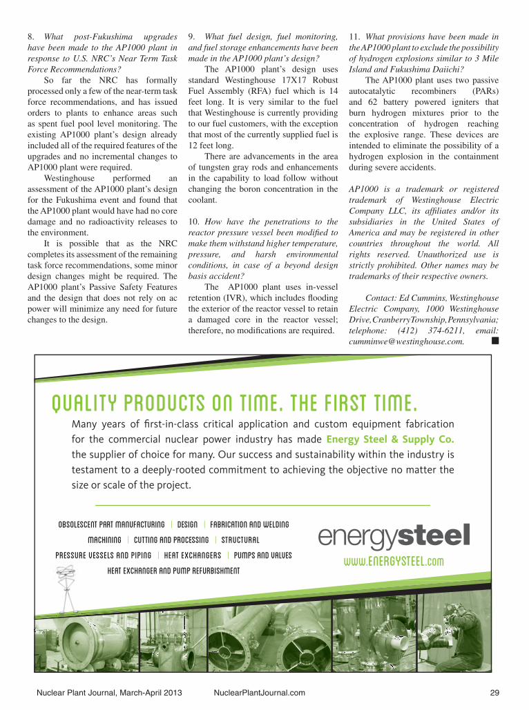
Nuclear Plant Journal, March-April 2013 NuclearPlantJournal.com 29
8. What post-Fukushima upgrades have been made to the AP1000 plant in response to U.S. NRC’s Near Term Task Force Recommendations?
So far the NRC has formally processed only a few of the near-term task force recommendations, and has issued orders to plants to enhance areas such as spent fuel pool level monitoring. The existing AP1000 plant’s design already included all of the required features of the upgrades and no incremental changes to AP1000 plant were required.
Westinghouse performed an assessment of the AP1000 plant’s design for the Fukushima event and found that the AP1000 plant would have had no core damage and no radioactivity releases to the environment.
It is possible that as the NRC completes its assessment of the remaining task force recommendations, some minor design changes might be required. The AP1000 plant’s Passive Safety Features and the design that does not rely on ac power will minimize any need for future changes to the design.
9. What fuel design, fuel monitoring, and fuel storage enhancements have been made in the AP1000 plant’s design?
The AP1000 plant’s design uses standard Westinghouse 17X17 Robust Fuel Assembly (RFA) fuel which is 14 feet long. It is very similar to the fuel that Westinghouse is currently providing to our fuel customers, with the exception that most of the currently supplied fuel is 12 feet long.
There are advancements in the area of tungsten gray rods and enhancements in the capability to load follow without changing the boron concentration in the coolant.
10. How have the penetrations to the reactor pressure vessel been modifi ed to make them withstand higher temperature, pressure, and harsh environmental conditions, in case of a beyond design basis accident?
The AP1000 plant uses in-vessel retention (IVR), which includes fl ooding the exterior of the reactor vessel to retain a damaged core in the reactor vessel; therefore, no modifi cations are required.
11. What provisions have been made in the AP1000 plant to exclude the possibility of hydrogen explosions similar to 3 Mile Island and Fukushima Daiichi?
The AP1000 plant uses two passive autocatalytic recombiners (PARs) and 62 battery powered igniters that burn hydrogen mixtures prior to the concentration of hydrogen reaching the explosive range. These devices are intended to eliminate the possibility of a hydrogen explosion in the containment during severe accidents.
AP1000 is a trademark or registered trademark of Westinghouse Electric Company LLC, its affi liates and/or its subsidiaries in the United States of America and may be registered in other countries throughout the world. All rights reserved. Unauthorized use is strictly prohibited. Other names may be trademarks of their respective owners.
Contact: Ed Cummins, Westinghouse Electric Company, 1000 Westinghouse Drive, Cranberry Township, Pennsylvania; telephone: (412) 374-6211, email: [email protected]. �
Quality Products on Time. the First Time.
www.energysteel.com
Many years of first-in-class critical application and custom equipment fabrication for the commercial nuclear power industry has made Energy Steel & Supply Co. the supplier of choice for many. Our success and sustainability within the industry is testament to a deeply-rooted commitment to achieving the objective no matter the size or scale of the project.
Obsolescent Part Manufacturing | Design | Fabrication and Welding
Machining | Cutting and Processing | Structural
Pressure Vessels and Piping | Heat Exchangers | Pumps and Valves Heat Exchanger and Pump Refurbishment

Old Reactors, New Tricks
An excerpt from the original article, “Old Reactors, New Tricks” by Leonard J Bond, Pacifi c Northwest National Laboratory (PNNL), which originally appeared in IEEE Spectrum Magazine, August 2012 issue, pages 30 to 35. Copyright 2012 IEEE.
My colleagues and I have sought new types of online monitoring and nondestructive testing technologies that can provide early warnings of degrading materials. Our goal has been to transition from the current “fi nd and fi x” approach to one we call “model and predict.”
Inside nuclear power station, fi erce forces are at work. In the pressurized water reactors (PWRs) and boiling water reactors (BWRs) that generate power in the United States, the nuclear cores consist of rods of uranium dioxide. Inside this radioactive material, a nuclear fi ssion reaction produces energy and many forms of radiation, including gamma rays and neutrons. The extremely high radiation levels are reduced by about a factor of 20 by the steel walls of a reactor pressure vessel, and then to safe levels by the massive reinforced concrete containment structure that jackets the vessel.
Both reactor types use water as the coolant. In a PWR, water enters the reactor core at about 275 °C and is heated as it fl ows upward through the core to a temperature of about 315 °C. The water remains liquid due to high pressure, usually around 15.5 megapascals (about 150 times the atmospheric pressure at sea level). In a BWR, the cooling water is maintained at about 7.6 MPa so that it boils in the core at about 285 °C. In both cases steam is produced to drive turbines that generate electricity.
High temperature, high pressure, and radiation all stress a reactor’s components. Inside a reactor, neutrons bombard the pressure vessel’s steel walls; over a period of years, that bombardment can cause reactions that displace atoms in the material and produce impurities and tiny voids. These microscopic phenomena can reduce the metal’s toughness and its ability to resist cracking.
The NRC and the nuclear industry, working with the Electric Power Research Institute, are now determining how to measure and monitor the aging of a reactor’s key components. The major concerns are embrittlement and cracking in the reactor pressure vessel and its piping; degradation of the concrete containment; aging cables; and corrosion in buried water pipes. At the moment we just don’t know which of these problems will be the most critical in any given plant. After all, no one has ever before operated a commercial-scale nuclear reactor for six or seven decades. We have entered a new era in the atomic age.
During the past 30 years, many parts of plants have been replaced or refurbished, including turbines, some major piping, and pressure vessel lids. But the central components of a nuclear plant—the pressure vessel itself and its reinforced concrete-and-steel containment—were never designed for replacement. The pressure vessel of a typical 1-gigawatt power plant weighs about 300 metric tons and is more than 12 meters (39 feet) tall. Most analysts believe that it would be easier to build a new plant than to cut into the containment to extract and replace a pressure vessel.
So how do you determine whether a vessel or another major component is robust enough to last another 20 years?
If you want to know what’s happening in an aging reactor, to really understand how its thick steel and tough concrete are faring after years of relentless bombardment, the best thing to do may be to listen to it. Nuclear researchers are now testing acoustic and ultrasonic monitoring techniques drawn from the civil and aerospace engineering communities. The same methods used to monitor the structural integrity of a bridge or an airplane may work for a nuclear pressure vessel as well.
One promising technique was demonstrated decades ago in an
operational nuclear plant. In 1989, inspectors at the Limerick Generating Station, in Pennsylvania, found a tiny crack in the welding around a pressure vessel pipe that brought cooling water into the bottom of the reactor. The operators concluded that the fl aw didn’t pose a threat, but they wanted to see if it was possible to monitor crack growth in an operating plant. They turned to a technique called acoustic emission monitoring, which is used to check on metallic structures like pipelines and wind-turbine blades. This method relies on the fact that when a crack grows, acoustic energy is released in tiny pulses—much the same way an earthquake sends out seismic waves. Once the acoustic system was installed, operators could listen for the ultrasonic waves that would indicate a growing fracture.
The acoustic system was kept in place for three years, during which time researchers listened in as one part of the crack grew to a depth of 12 millimeters. The system also detected the growth of minuscule cracks that wouldn’t have been noted by traditional monitoring methods, and researchers deemed the technology demonstration a success. In the decades since, fossil-fueled power plants and petrochemical facilities have installed acoustic emission systems to monitor vessels and pipes. However, nuclear power stations in the United States have been slow to adopt this proven technology.
With advances in both computer hardware and processing software, acoustic emission systems are now little larger than a laptop and are capable of displaying data nearly in real time. At Pacifi c Northwest National Laboratory, (PNNL) Richland, Washington, my colleagues and I recently tested acoustic emission monitoring along with another technique for metal monitoring that makes use of “guided waves.” In this technique, transducers generate ultrasonic waves with specifi c frequencies, which propagate through a structure such as a metal pipe or the walls of a pressure vessel. Because the ultrasonic waves are scattered and refl ected by discontinuities in a material, they can provide clear indications of cracks or corrosion. This technique could be particularly useful because it wouldn’t require inspectors to strip off insulation to inspect pipes,
30 NuclearPlantJournal.com Nuclear Plant Journal, March-April 2013
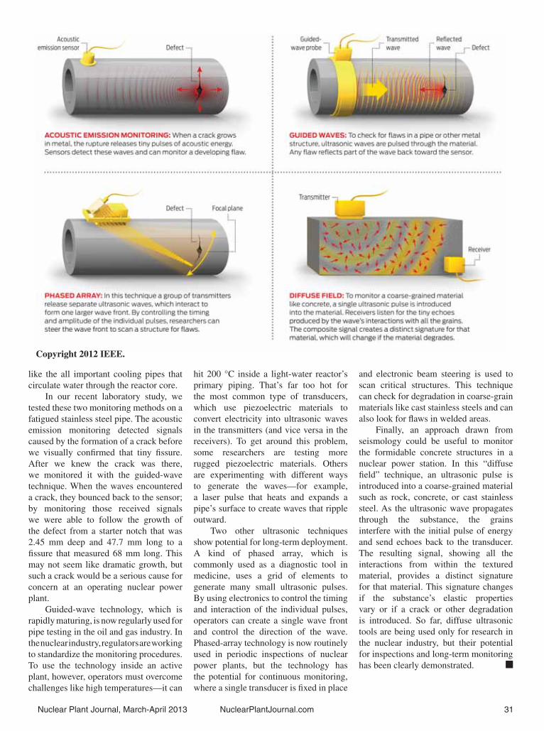
Nuclear Plant Journal, March-April 2013 NuclearPlantJournal.com 31
like the all important cooling pipes that circulate water through the reactor core.
In our recent laboratory study, we tested these two monitoring methods on a fatigued stainless steel pipe. The acoustic emission monitoring detected signals caused by the formation of a crack before we visually confi rmed that tiny fi ssure. After we knew the crack was there, we monitored it with the guided-wave technique. When the waves encountered a crack, they bounced back to the sensor; by monitoring those received signals we were able to follow the growth of the defect from a starter notch that was 2.45 mm deep and 47.7 mm long to a fi ssure that measured 68 mm long. This may not seem like dramatic growth, but such a crack would be a serious cause for concern at an operating nuclear power plant.
Guided-wave technology, which is rapidly maturing, is now regularly used for pipe testing in the oil and gas industry. In the nuclear industry, regulators are working to standardize the monitoring procedures. To use the technology inside an active plant, however, operators must overcome challenges like high temperatures—it can
hit 200 °C inside a light-water reactor’s primary piping. That’s far too hot for the most common type of transducers, which use piezoelectric materials to convert electricity into ultrasonic waves in the transmitters (and vice versa in the receivers). To get around this problem, some researchers are testing more rugged piezoelectric materials. Others are experimenting with different ways to generate the waves—for example, a laser pulse that heats and expands a pipe’s surface to create waves that ripple outward.
Two other ultrasonic techniques show potential for long-term deployment. A kind of phased array, which is commonly used as a diagnostic tool in medicine, uses a grid of elements to generate many small ultrasonic pulses. By using electronics to control the timing and interaction of the individual pulses, operators can create a single wave front and control the direction of the wave. Phased-array technology is now routinely used in periodic inspections of nuclear power plants, but the technology has the potential for continuous monitoring, where a single transducer is fi xed in place
and electronic beam steering is used to scan critical structures. This technique can check for degradation in coarse-grain materials like cast stainless steels and can also look for fl aws in welded areas.
Finally, an approach drawn from seismology could be useful to monitor the formidable concrete structures in a nuclear power station. In this “diffuse fi eld” technique, an ultrasonic pulse is introduced into a coarse-grained material such as rock, concrete, or cast stainless steel. As the ultrasonic wave propagates through the substance, the grains interfere with the initial pulse of energy and send echoes back to the transducer. The resulting signal, showing all the interactions from within the textured material, provides a distinct signature for that material. This signature changes if the substance’s elastic properties vary or if a crack or other degradation is introduced. So far, diffuse ultrasonic tools are being used only for research in the nuclear industry, but their potential for inspections and long-term monitoring has been clearly demonstrated. �
Copyright 2012 IEEE.

(Continued on page 34)
On-line MonitoringBy Richard Rusaw, Electric Power Research Institute.
1. How will the online monitoring system help predict equipment/structure failure in advance before it becomes a problem?
Online equipment condition monitoring can provide early warning of potential failure by detecting incipient indicators of equipment degradation via advanced pattern recognition and signal processing technologies. Today’s on-line monitoring (OLM) systems/programs are built around pattern recognition software that models normal system or component behaviors by evaluating real-time operational conditions against the model’s predicted behavior with a high degree of sensitivity. Any signifi cant deviation from predicted behavior is identifi ed well in advance of any traditional form of condition monitoring. This capability allows plant operators to take actions before degrading conditions result in damaged or failed systems, structures, or components.
To provide early warning, commercial OLM products rely on a continuous input of well-correlated plant data, typically available only for active assets. After the initial warning, an investigative review can identify the actual failure mode and cause and suggest corrective actions. The investigative review can involve plant staff as well as experts in predictive maintenance. In these cases, the diagnostic process can be manually intensive.
For utilities using OLM, a more automated diagnostic and prognostic capability could directly identify
equipment condition from the “signature” of the initial warning. This capability would not only reduce manual resources required for diagnosing failures, but also improve the effectiveness of condition corrections. A more timely response can, in some cases, signifi cantly improve safety and prevent collateral damage.
EPRI is currently developing diagnostics and prognostics capabilities to address these gaps in plant asset condition assessment. A Fleet-wide Prognostics and Health Management (FW-PHM) software suite currently in Beta testing will provide an industry-wide database of failure mode indicators for a wide variety of power plant assets. The software
includes a “reasoner” that uses this fault signature database for assessing current plant information to determine the likely cause for any anomalies detected in the plant data. The diagnostic advice included in the software can reduce the time and resources required for troubleshooting and diagnosing impending failures, thereby increasing the amount of time available to respond with a corrective action. Further, the suite’s prognostic models can provide a sound estimate of the remaining time available before a degrading asset reaches a critical condition. This information can be used to prioritize and plan responsive actions and can assist plant personnel in more frequently assessing the potential impact of a developing problem.
2. How will the online monitoring system help reduce human errors?
Monitoring programs provide a means for accurately assessing asset conditions, potentially enabling users to reduce operating and maintenance costs by moving from a time-based preventative maintenance program to an asset condition-based program. Industry experience has shown that time-based programs can result in equipment being serviced well in advance of condition requirements. Condition-based programs can avoid unnecessary maintenance, reducing opportunities for human errors during maintenance of plant assets. An additional means of error reduction
results from the application of monitoring programs to quickly identify the proper equipment failure modes and causes of active component failures. Traditional forms of diagnostics on equipment faults provide a higher probability environment to introduce human errors. The elimination of potential root causes with automated assessment or diagnostics reduces the potential for human error during corrective maintenance activities.
3. What are the main technologies that have been used in the online monitoring system?
Advanced Pattern Recognition Software- Centralized online monitoring is a highly automated condition analysis
Overview of the PHM Suite
32 NuclearPlantJournal.com Nuclear Plant Journal, March-April 2013
Response to questions by Newal Agnihotri, Editor of Nuclear Plant Journal.

That’s better! You see, at Rolls-Royce we know just how important it is to
keep your customers operational. Because, if they can switch the light on
without a second thought, then we know we’re fulfilling our part as your
long-term nuclear services provider. Rolls-Royce has over 40 years of experience
in designing custom solutions that enable optimal lifetime performance.
In addressing utilities’ most complex challenges, we have established
a comprehensive range of nuclear services for operational reactors across
Europe, North America and Asia, from remote tool design and delivery to
total fleet management solutions. It’s good to shed some light.
Trusted to deliver excellence
www.rolls-royce.com/nuclear
In the dark about nuclear services? Let’s switch the light on.

34 NuclearPlantJournal.com Nuclear Plant Journal, March-April 2013
On-line Monitoring...Continued from page 32
and asset management system designed to capture and incorporate knowledge, experience, and intelligence from diversifi ed operating systems and monitoring environments. Advanced pattern recognition modeling is a fundamentally different approach from data trending analysis. With data trending, the primary knowledge source is trained plant personnel, who can view trends and understand when data has changed based on their experience of the system. With advanced pattern recognition modeling, the primary knowledge source is a trained numerical model, and in many cases, the numerical models can automatically detect much smaller changes than is possible with data trending. Further, numerical models are amenable to higher levels of automation and integration into advanced information management systems, thereby supporting modern business management programs.
Digital measurement and signal processing- Monitoring technologies enable more effective analysis of systems, structures, and components (SSCs). Nuclear plants were originally equipped with a minimum set of measurements and signals to support plant operation and protection systems. These measurements are primarily based on the original analog technologies available during the plant design and construction phases. To more fully assess SSC conditions, additional measurements are needed as inputs to monitoring programs. Vibration, temperature and fl ow monitoring of specifi c equipment are examples of measurements required for modeling and analysis of SSCs. Data preprocessing also is important because large amounts of data do not provide useful actionable information. Preprocessing technologies are used to condense large amounts of data into organized sets of data for effi cient use in analytical programs.
Modeling of system and component behaviors-The application of monitoring technologies requires a greater understanding of system and component
behaviors as precursors to model development. Monitoring programs do not have inherent intelligence about the behavior of monitored equipment or systems. Application of these programs
generated a need for greater intelligence and research in support of component behavior and the modeling of monitored SSCs.
Analytical methods to optimize measurement and data requirements-Performance and condition analysis identifi ed the need for advanced analytical methods to defi ne the measurement and data requirements for classes of SSCs. The integration of data processing, analog systems, digital systems, and variations in measurement quantity and quality results in low-value data inputs to the analytical engines. High-performance results for effectiveness required development of analytical methods to optimize data requirements and supporting measurements.
Information Management and industrial business applications- A key functional requirement of a well-developed monitoring program is its information interface with the operating plant and associated staff. The integration of advanced information detailing operating conditions of a wide range of plant assets into individual plants is an important step in implementing monitoring programs. This step must be analyzed, designed, planned, published, and managed for success and maximize the return on the OLM program investment.
4. Will the monitoring system help extend the life of the plants? If so, please explain how.
OLM systems are effective at identifying equipment operating in
conditions that may shorten their remaining life. Monitoring programs inform life extension decisions by identifying conditions that contribute to asset life limiting or reduction behaviors. They also provide the ability to gather substantially more data through automated means and to analyze and trend performance using new methods to make more informed decisions about nuclear plant operation and safety management.
OLM programs process sensor signals to derive parameter estimates of specifi c aging and performance features required to characterize the state and condition of material properties. This information can then be used to refi ne “diagnostic” assessments about material aging and degradation, enabling more accurate understanding of a system’s ability to achieve its design function and the types and timing of needed interventions. Of particular importance will be the capability to determine the “remaining useful life” of a component to justify its continued operation over an extended plant life or until the next scheduled maintenance opportunity.
Exelon is applying EPRI-developed fl eetwide online monitoring technology at its 17 nuclear units to improve plant productivity, equipment reliability, and optimize long-term plant management.
Contact: Richard Rusaw, Electric Power Research Institute, email: [email protected]. �
(Continued on page 36)
Spent Fuel Pool MonitoringBy H.M. Hashemian, Jonathan Edwards, Micah McFarland, and W.S. Johnson, Analysis and Measurement Services Corporation.
H.M. HashemianDr. H.M. Hashemian is president of Analysis and Measurement Services Corporation, an instrumentation and control systems testing company headquartered in Knoxville, Tennessee, with a worldwide list of clients. He holds three doctorates in Electrical Engineering, Nuclear Engineering, and Computer Engineering.
Dr. Hashemian specializes in process instrumentation, equipment condition monitoring, on-line diagnostics of anomalies in industrial equipment and processes, automated testing, and technical training. He is the author of 2 books, 10 book chapters, 50 peer-reviewed journal articles, and more than 250 conference papers. He holds 15 U.S. patents (9 awarded and 6 pending) and is a Fellow of the International Society of Automation (ISA), a Senior Member of the Institute of Electrical and Electronics Engineers (IEEE), and a member of the American Nuclear Society (ANS) and the European Nuclear Society (ENS).
SummaryFollowing the events at Japan’s
Fukushima Dai-ichi Nuclear Power Plant in March 2011, the Nuclear Regulatory Commission (NRC) is emphasizing the need for improved monitoring of spent fuel pools. An NRC task force found that, “The lack of information on the conditions of the fuel in the Fukushima spent fuel pools … contributed to a poor understanding of possible radiation releases and to confusion about the need and priorities for support equipment. The Task Force therefore concludes that reliable information on the conditions in the spent fuel pool is essential to any
effective response to a prolonged station blackout or other similarly challenging accident.”
This paper presents the design of a robust, cost-effective solution for enhanced spent fuel pool monitoring, integrating com-mercially available wide-range instru-mentation (e.g., level sensors, temperature sensors, radiation-hardened video equipment) with ex-
isting wireless data transmission devices. Wireless data transmission will reduce in-stallation costs, minimize the addition of combustible material, and help overcome issues associated with a potentially com-promised cabling infrastructure caused by an accident. This system can be used to retrofi t the existing fl eet of nuclear power plants to address post-Fukushima requirements, as well as contribute to the design of enhanced condition monitoring equipment and techniques for instrument-ing spent fuel pools in the next generation of nuclear facilities.
IntroductionAfter spent nuclear fuel assemblies
are removed from a plant’s reactor, they are maintained under water in a spent fuel pool prior to long-term storage in dry casks or a permanent storage facility. The water in the pool serves to cool the
spent fuel assemblies, while preventing radiation leakage to the surrounding environment. It is well-known that the Zircaloy cladding used in nuclear fuel assemblies, when oxidized by steam, produces combustible hydrogen. This can occur if the assemblies are exposed to air in either the reactor core or the spent fuel pool. Such an event took place at the Fukushima Dai-ichi nuclear power plant in March 2011. After the explosions in the reactor building of a previously shutdown unit, plant operators initially speculated that the water level in the spent fuel pool had dropped, exposing the spent fuel assemblies, leading to hydrogen production as well as spent fuel overheating and radiation leakage. Though it was later determined that the spent fuel was suffi ciently immersed and that the hydrogen was actually produced in the reactor core of a conjoined unit, the lack of pool condition information forced emergency responders to divert signifi cant time and manpower to assessing a spent fuel pool problem that ultimately did not exist.
The event at Fukushima Dai-ichi has served to heighten awareness in the nuclear industry that existing instrumentation cannot adequately inform plant operators of the pool conditions outside normal operations. As such, the NRC has issued Order EA-12-051, “Order to Modify Licenses with Regard to Reliable Spent Fuel Pool Instrumentation”, which requires all licensees to monitor the spent fuel pool water level at three distinct depths (as shown in Figure 1).
Current industry practice for spent fuel monitoring often involves the use of narrow-range instrumentation, as well as limit switches, to detect when pool parameters exceed acceptable limits. This approach enables plant personnel to detect the onset of a potential problem, but it does not offer any indication of the severity of a developing problem. For example, if the water level in the spent fuel pool begins to drop, the level sensor will indicate the declining level. However, if the water level drops below the sensor’s narrow detection range, the operators would be unaware of the exact level.
One solution would be to simply install additional narrow-range depth
Nuclear Plant Journal, March-April 2013 NuclearPlantJournal.com 35

36 NuclearPlantJournal.com Nuclear Plant Journal, March-April 2013
Spent Fuel...Continued from page 35
sensors. This approach is problematic for plants because the addition of multiple long cable runs adds combustible material to the containment environment, which plants are required to minimize. Furthermore, some plant budgets are unlikely to support the high labor
and material costs associated with installing and maintaining the additional cable infrastructure which, as seen at Fukushima, can be easily compromised during an accident. As such, a different approach is needed as described in this paper.
System DescriptionThe solution is a robust, cost-effective
system for enhanced spent fuel pool monitoring, integrating commercially available wide-range instrumentation (e.g., level sensors, temperature sensors, radiation-hardened video equipment) with existing wireless data transmission devices. Though the NRC only requires monitoring the water level, this design can accommodate other parameters, such
as water temperature and recirculation fl ow, which can contribute to producing a more complete picture of the fuel pool condition both during and after an accident. Additionally, radiation-hardened video equipment would provide continuous surveillance of critical
components and conditions in and around the spent fuel pool.
There are a number of important benefi ts to wireless data transmission. Wireless systems eliminate costs associated with installing and maintaining long cable runs, minimize the addition of combustible material, and help overcome issues associated with aging or compromised cables.
Figure 2 is a graphical representation of the wireless system design. The design uses conventional instrumentation wired directly to a remote unit that provides both instrument power and wireless data communication to a hub. The hub receives wireless data from one or more remotes and transmits the data over a wired link through a penetration and then onto the plant network.
While the design would most likely be powered with 120Vac, it is anticipated that a rechargeable battery backup system is also needed for both the remote and the hub. The battery backup would engage in the event of a loss of power to the unit and enable the sensors to maintain function and transmission for a limited period of time under post-accident conditions.
Challenges with Wireless Implementation
Nuclear power plants have been slow to incorporate newer technologies, such as wireless data transmission, often due to concerns regarding electromagnetic compatibility (EMC) and cyber security. A legitimate concern is that wireless transmissions may adversely impact the electrical equipment and systems within the vicinity of the wireless device. To address this concern, a number of steps may be taken. This includes characterizing the electromagnetic environment (EME) of the intended installation area, identifying systems vulnerable to electromagnetic interference (EMI) through walkdowns and targeted immunity testing, and establishing exclusion zones where wireless transmissions are not permitted based upon the power level of the transmitter.
Recent high-profi le computer virus attacks have heightened concerns regarding the security of nuclear power plant computer networks (cyber security). An effective cyber security program prevents malicious intrusion into plant systems by ensuring that network devices are only accessed by employees and other devices with proper credentials. Wireless devices incorporate security protocols, such as Wi-Fi Protected Access II (WPA2) available in Wi-Fi networks IEEE 802.11b, 802.11g, and 802.11n, to maintain access integrity; these protocols meet or exceed the guidelines established in IEEE 802.11i and NIST FIPS 140-2.

Nuclear Plant Journal, March-April 2013 NuclearPlantJournal.com 37
Wireless vibration monitoring systems have been successfully deployed by AMS at the Arkansas Nuclear One (ANO) nuclear power plant, Commanche Peak nuclear power plant, as well as the High Flux Isotope Reactor (HFIR) at the Oak Ridge National Lab. In doing so, all
questions regarding EMC and cyber security were resolved to the satisfaction of the plant management.
ConclusionThe system described here will pro-
vide nuclear plant operators with a great-
er understanding of spent fuel pool condi-tions, such as water level and temperature, in both normal and post-accident scenar-ios. Additionally, the implementation of new spent fuel pool instrumentation for continuous monitoring in beyond design basis events, such as the Fukushima ac-cident, would allow for effective, targeted emergency response procedures. As a re-sult, an increased level of safety will be achieved in the current fl eet of nuclear plants and in the next generation of reac-tors as they come online.
Contact: Dr. H.M. Hashemian, Analysis and Measurement Services Corporation, AMS Technology Center, 9119 Cross Park Drive, Knoxville, Tennessee 37923; telephone: (865) 691-1756, email: [email protected]. �
©2013
for Nuclear Plant Maintenance, Construction and Decommissioning
TRI TOOL INC.TRI TOOL THERMAL SERVICESSM
On-Site Contract Machining and Welding ServicesAs an OEM manufacturer, Tri Tool produces an extensive line of machining and automated welding
equipment. This resource is our Toolbox. Tri Tool is prepared to support your projects with nuclear
qualified personnel and the equipment to get the job done right, on schedule and on budget.
Specialized Machine Tool Design and ManufacturingWhen your project calls for unique or custom machinery, Tri Tool can design and custom manufacture
automated, manual or remote control equipment to address your most demanding applications.
Contact Tri Tool for reliable equipment, service or welding assistance for your next project.
©201
A critical weld in a nuclear power plant being performed by Tri Tool Thermal ServicesSM
with Tri Tool’s new DualARC® multi-process GTAW/GMAW/GMAW-P/FCAW weld head and OrbitMaster® Programmable Arc Controller.
Dependable Equipment TechnologyDependable Equipment Technology

Robotic Pipe Inspection to Meet License Renewal CommitmentsBy David Bremer, Cooper Nuclear Station.
David BremerDavid Bremer has been with Cooper Nuclear Station for more than 30 years. Since the project’s inception in 2005, he has served as the license renewal project manager, with the previous 25 years spent in Operations.
Dave began his nuclear career in the US Navy and has a BS in Nuclear Technology from Peru State College. He is an active member in the NEI-sponsored License Renewal Taskforce and the Implementation Working Group.
US nuclear power plants contain ex-tensive piping systems, many of which are buried underground, in constant con-tact with soil. These plant piping sys-tems often contain potentially-hazardous substances such as diesel oil, or coolant water containing small levels of tritium. Because these buried pipes are vulnerable to degradation from internal and external corrosion, nuclear plant operators are ob-ligated to maintain buried pipe programs that identify, rank, monitor, and inspect these piping systems. These activities are driven by industry mandates such as NEI 09-14 (Guideline for the Management of Underground Piping and Tank Integ-rity), NEI 07-07 (Industry Ground Wa-ter Protection Initiative- Final Guidance Document) groundwater protection, or
required relicensing commitments.
Cooper Nuclear Station (CNS) is an 830 MWe BWR-4 located in Browns-ville, Nebraska, which began com-mercial operation in 1974. CNS main-tains a buried pipe inspection and mon-itoring program that began in the Spring
of 2011, consisting of 21 plant systems that account for a total piping length of 60,406 feet. Since CNS’ buried pipe pro-gram inception, we have completed 4 to-
tal pipe inspections: 2 excavations, 1 Area Potential-Earth Current (APEC) survey, Soil Analysis, and 1 in-line inspection (ILI). The in-line inspection was the fi rst
of its kind in the US nuclear power indus-try, and is the subject of this article.
License Renewal Inspection
As part of Cooper Nuclear Station’s 2010 license renewal, a commitment was made that 6 piping systems be inspected prior to the start of the extended operation period. One of these systems was our High Pressure Coolant Injection (HPCI) line. This safety-related piping system transports demineralized water from the Emergency Condensate Storage Tank (ECST) room in the Control Building (where the control room is located) basement to the safety injection systems in the Reactor Building. Since the inspection needed to be conducted while the plant was offl ine, CNS scheduled the inspection to coincide with our Fall 2012 refueling outage.
The line to be inspected was a 30 foot section of 18-inch Schedule XS (0.500") carbon steel pipe with two welded vertical 45° elbow fi ttings. The only access to the system was via an opening in the ECST room, so it was decided that a robotic in-line inspection was the most practical, comprehensive, and cost-effective means of completing the inspection.
CNS’ Senior Nuclear Safety Assurance Group Analyst, David Bremer, contracted the team of Diakont and Structural Integrity Associates, Inc. (SI) to perform the robotic inspection and fl aw evaluation of the HPCI system piping.
The Diakont/SI team was selected because it offered a “turnkey” approach to the complete project, including inspection, analysis, and data management. Diakont’s
HPCI Piping Requiring Inspection for Extended Operation.
(Continued on page 40)
38 NuclearPlantJournal.com Nuclear Plant Journal, March-April 2013

www.diakont.com | 858.551.5551
DIAKONT SPECIALIZES IN... Rad-Tolerant Cameras and CCTV Systems Custom Robotics Nuclear I&C Systems
Fuel Handling Equipment Buried Pipe Inspection
YOUR BURIED PIPING INSPECTION SOLUTION
Have Diakont perform in-line inspection of your plant’s buried piping, and meet your NEI 09-14 obligations
Diakont’s inspection teams use self-propelled robots to overcome buried pipe NDE challenges:
100% non-contact internal ultrasonic inspection of 16”-54” pipes, using patented EMAT technology
High-precision detection and measurement of indications
Graphical reporting and integration with BPWorks database
Robots capable of navigating elbows and vertical pipe sections
Call Diakont today to receive information on the industry’s only comprehensive nuclear buried pipe
inspection solution.
Inspection without Excavation
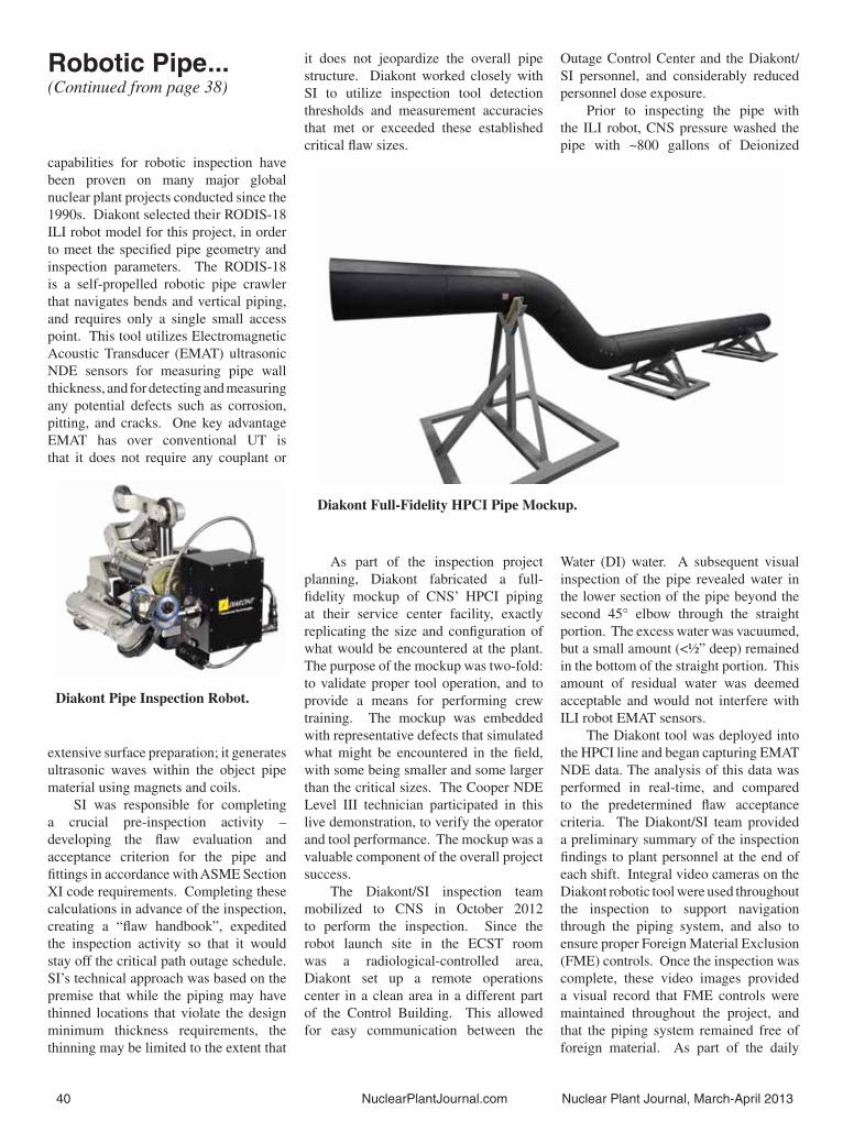
40 NuclearPlantJournal.com Nuclear Plant Journal, March-April 2013
capabilities for robotic inspection have been proven on many major global nuclear plant projects conducted since the 1990s. Diakont selected their RODIS-18 ILI robot model for this project, in order to meet the specifi ed pipe geometry and inspection parameters. The RODIS-18 is a self-propelled robotic pipe crawler that navigates bends and vertical piping, and requires only a single small access point. This tool utilizes Electromagnetic Acoustic Transducer (EMAT) ultrasonic NDE sensors for measuring pipe wall thickness, and for detecting and measuring any potential defects such as corrosion, pitting, and cracks. One key advantage EMAT has over conventional UT is that it does not require any couplant or
extensive surface preparation; it generates ultrasonic waves within the object pipe material using magnets and coils.
SI was responsible for completing a crucial pre-inspection activity – developing the fl aw evaluation and acceptance criterion for the pipe and fi ttings in accordance with ASME Section XI code requirements. Completing these calculations in advance of the inspection, creating a “fl aw handbook”, expedited the inspection activity so that it would stay off the critical path outage schedule. SI’s technical approach was based on the premise that while the piping may have thinned locations that violate the design minimum thickness requirements, the thinning may be limited to the extent that
it does not jeopardize the overall pipe structure. Diakont worked closely with SI to utilize inspection tool detection thresholds and measurement accuracies that met or exceeded these established critical fl aw sizes.
As part of the inspection project planning, Diakont fabricated a full-fi delity mockup of CNS’ HPCI piping at their service center facility, exactly replicating the size and confi guration of what would be encountered at the plant. The purpose of the mockup was two-fold: to validate proper tool operation, and to provide a means for performing crew training. The mockup was embedded with representative defects that simulated what might be encountered in the fi eld, with some being smaller and some larger than the critical sizes. The Cooper NDE Level III technician participated in this live demonstration, to verify the operator and tool performance. The mockup was a valuable component of the overall project success.
The Diakont/SI inspection team mobilized to CNS in October 2012 to perform the inspection. Since the robot launch site in the ECST room was a radiological-controlled area, Diakont set up a remote operations center in a clean area in a different part of the Control Building. This allowed for easy communication between the
Outage Control Center and the Diakont/SI personnel, and considerably reduced personnel dose exposure.
Prior to inspecting the pipe with the ILI robot, CNS pressure washed the pipe with ~800 gallons of Deionized
Water (DI) water. A subsequent visual inspection of the pipe revealed water in the lower section of the pipe beyond the second 45° elbow through the straight portion. The excess water was vacuumed, but a small amount (<½” deep) remained in the bottom of the straight portion. This amount of residual water was deemed acceptable and would not interfere with ILI robot EMAT sensors.
The Diakont tool was deployed into the HPCI line and began capturing EMAT NDE data. The analysis of this data was performed in real-time, and compared to the predetermined fl aw acceptance criteria. The Diakont/SI team provided a preliminary summary of the inspection fi ndings to plant personnel at the end of each shift. Integral video cameras on the Diakont robotic tool were used throughout the inspection to support navigation through the piping system, and also to ensure proper Foreign Material Exclusion (FME) controls. Once the inspection was complete, these video images provided a visual record that FME controls were maintained throughout the project, and that the piping system remained free of foreign material. As part of the daily
Diakont Pipe Inspection Robot.
Diakont Full-Fidelity HPCI Pipe Mockup.
Robotic Pipe...(Continued from page 38)

Nuclear Plant Journal, March-April 2013 NuclearPlantJournal.com 41
ILI activities, EMAT functionality was validated at the beginning and end of each shift by running the ILI robot through a 6’ pipe spool containing embedded defects. This pipe spool, fabricated by CNS, was located adjacent to the robot launch site and had negligible impact to our project schedule.
Inspection ResultsThe Diakont/SI team successfully
completed the HPCI robotic inspection project, achieving 100% inspection coverage throughout the entire planned inspection scope, within the designated outage timeframe. The high-resolution Diakont robotic NDE tool detected only four minor anomalies, all in the lower half of a 45° elbow fi tting. These anomalies were characterized as internal (process side) corrosion, but all measured remaining wall thickness values exceeded 87.5% of the nominal pipe wall thickness (i.e. the manufacturer tolerance). The inspection fi ndings were presented to the Cooper NDE Level III, who confi rmed that the internal anomalies had no structural signifi cance. The safety-related HPCI piping system was determined to have no thinning beyond the critical threshold, and was returned to service immediately following the completion of the inspection. The inspection data from this inspection was entered into the site’s BPWorks™ buried pipe inspection database for future use in risk ranking or inspection planning purposes in support of the site’s NEI 09-14 (Guideline for the Management of Underground Piping and Tank Integrity) and to meet CNS’ license renewal commitment.
This project demonstrated the successful use of established pre-evaluation fl aw criteria, in order to expedite critical outage-driven inspections, and the use of robotic in-line inspection tools to obtain nuclear plant buried piping integrity data on a safety-related system.
Contact: Keith Reeser, Diakont, 3821-C Calle Fortunada, San Diego, California 92123; telephone: (858) 551-5551, email: [email protected]. �
YOU GENERATE THE POWER
WE’LL GENERATE THE SOLUTIONS
CELEBRATING
Y E A R S1983-2013
www.structint.com/nei
( 8 7 7 - 4 S I - P O W E R )8 7 7 - 4 7 4 - 7 6 9 3
Nuclear power plant operating practices/experience and related decision making are highly scrutinized by many stakeholders. At the same time, your customers rely on you to keep the power on. Structural Integrity can provide solutions to help you meet your demands so you can focus on delivering power.
With 30 years in business in the power industry, you can rely on us to help you and take some of the burden off your shoulders. We’re a company you can trust to work hard and to provide innovative, top quality, high value solutions on every project, including support of:
Fatigue AnalysisBuried piping programs, inspection & remediationLicense Renewal applications and commitmentsBWR and PWR internals evaluationDegraded component assessmentsNon-destructive examinationSeismic Analysis
Scan the QR Code for more information
Generating Solutions for 30 Years.

Mastering Breaker MaintenanceBy Gregory Lichty, Public Service Electric and Gas Company and Dave Davis, AZZ | NLI.
Gregory LichtyOriginally from Somerset, Pennsylvania, Greg served 22 years in the US Navy, retiring in February, 2003 as a Senior Chief Electrician. He began work at PSEG’s Hope Creek Nuclear Generating Station in February, 2003 as an Electrical Maintenance Supervisor which was his primary job for fi ve years. In February, 2008, he was hired into the Maintenance Department’s position of Component Specialist for the station’s air circuit breakers and motors. While being a Component Specialist is his primary job at Hope Creek, he still supports Salem and Hope Creek’s refueling outages in the role of an Electrical Maintenance Supervisor. He is an active participant in EPRI’s Circuit Breaker User Group as well as the Large Electric Motor User Group. Greg graduated in June, 2000 with a Bachelors of Science Degree in Business Administration from the University of New Haven, New Haven, Connecticut and in June, 2010 he received an MBA from Georgian Court University in Lakewood, New Jersey.
Introduction“The greatest victory is that which
requires no battle.” Sun Tzu wrote this some 2,500 years ago in his famous work, The Art of War. As with many quotes attributed to Sun Tzu, we can apply this same phrase or idea to topics unrelated to actual war. When applied to low voltage breaker maintenance, we might declare, “The best way to perform breaker maintenance is to eliminate the need for it.”
Most nuclear plants in the US began operation in the 1970s and 80s, took more than a decade to construct, and were designed using modern technologies of the day. This means that any original plant equipment was likely designed
in the 1950s or 60s. Changes in equipment over the last half-century may not be quite as stark for some mechanical equipment (a six-inch carbon steel gate valve available today isn’t all that different from one installed decades ago), but for most electrical and electronic equipment, the
differences are like night and day. To make this point, we will focus on one common product used in all nuclear plants - low voltage circuit breakers used in AC and DC applications.
Low Voltage Breakers & Maintenance
Rated at 600 volts and below, the largest of these breakers can carry up to 4,000 amps, but most breakers typically have 800 to 2,000 ampere frame sizes. A typical nuclear plant has roughly 300 of these breakers installed in switchgear. The purpose of a circuit breaker in a nuclear plant is to operate (start and stop) electrical equipment, and in the event of a fault, to break a circuit by opening (tripping) and deenergizing the circuit to protect the downstream load.
The tripping process requires contacts to separate very rapidly under high amperage levels and the mechanism
responsible for this operation is under tremendous spring tension. Whether performed manually or automatically, tripping a low voltage breaker is a fairly violent event from a mechanical perspective. Even though circuit breakers are in electrical systems, they’re mechanical devices. There are numerous bearings, bushings, springs, levers, arms, and the entire assembly can be very maintenance intensive.
The two biggest challenges to breaker maintenance are the shrinking number of skilled maintenance personnel and scarcity of replacement parts, including rebuild kits for legacy circuit breakers. This is especially true for nuclear safety-related applications. There are several different strategies for maintaining circuit breakers, but the main options are to use in-house or outside resources, overhaul (rebuild) the breakers on or off-site, and to rebuild spare breakers when time permits and swap them out during outages. Whichever combination of variables is chosen, this is an expensive endeavor.
Fast-forward to modern low voltage breakers. Composite materials have replaced most of the metal frame structure and superior manufacturing techniques and materials allow for a more compact design; sometimes occupying half the volume of the original circuit breaker. Modern breakers have far fewer parts and require less maintenance. So much less maintenance, that a modern breaker may not require an overhaul for forty years and need only be cycled periodically to redistribute the lubricant. It is important to note that modern lubricants are far superior to the grease used in legacy breakers and grease hardening in legacy breakers is the leading cause of breaker failures.
A new industrial facility being built today, including a new nuclear plant, would use modern breakers installed into modern switchgear. The smaller breakers allow for more breakers per volume of switchgear, so new plants will have less switchgear. An older non-nuclear industrial facility wishing to upgrade may simply replace its switchgear allowing for new breakers to be used. But most nuclear plants consider replacing switchgear too extensive of a modifi cation. This is the quandary faced by many nuclear plants;
42 NuclearPlantJournal.com Nuclear Plant Journal, March-April 2013

Nuclear Plant Journal, March-April 2013 NuclearPlantJournal.com 43
Dave DavisDave Davis joined NLI in 2007 and
is currently the Site Manager for the Southeast Region. Dave is responsible for all sales activities in the southeast
US and is NLI’s resident expert
on breakers and switchgear. Prior
to joining NLI, Dave was the
Circuit Breaker Program Manager
at PSEG’s Hope Creek Nuclear Plant. During
that period he also served as chairman of the EPRI Circuit
Breaker Users Group. Dave’s
nuclear career began in the Navy in 1976 as an electrician on nuclear
submarines and later was commissioned in the Limited Duty Offi cer (LDO)
Program. After the Navy, Dave worked for ABB Service as a fi eld engineer and
QA Manager for the nuclear services group.
large obsolete and maintenance intensive legacy breakers, and modern replacements that cannot directly replace the legacy breakers due to the size difference.
Weighing the OptionsThe situation described above was
faced by PSEG’s Hope Creek Generating Station a decade ago. Back then Dave Davis was a component specialist in the plant’s maintenance department, and Greg Lichty was one of the station’s Electrical Maintenance Supervisors. Hope Creek began commercial operation in 1986, and in 2002 as the breakers were nearing time for refurbishment, the plant began experiencing a growing number of performance issues with their low voltage breakers. The breaker OEM recommended a complete refurbishment after twenty years of use. With the current performance issues and the looming need for more than 250 breaker refurbishments, Hope Creek began in earnest to develop a game plan.
Seeking a broader perspective, PSEG Nuclear commissioned the Elec-tric Power Research Institute (EPRI) to conduct a facility lifecycle management plan, which included an evaluation of its
circuit breakers. In a parallel effort, Nu-clear Logistics Inc. (NLI) and two other well-known breaker suppliers were asked to provide budgetary estimates for refur-bishment of the legacy breakers as well as breaker replacement solutions.
The replacement breaker solution of-fered by NLI was the Square D Masterpact low voltage breaker. The Masterpact is available in an NT version for appli-cations up to 800 amps, and a slightly larger NW version for applications up to 3,000 amps. Both NT and NW break-ers can be used for AC and DC circuits and are available with the SureTrip solid state trip unit for DC applications and several versions of the Square D Micro-logic digital trip unit for AC applications. The Masterpact breaker can also be out-fi tted with all the optional accessories found on the original legacy breakers. In short, if Hope Creek was going to replace
their breakers, the Masterpact was a good choice – except that it wouldn’t fi t into Hope Creek’s switchgear.
The solution offered for the fi t issue was a custom “cradle.” Except when viewed from the front, the cradle looks similar to the originally installed circuit breaker. It has primary and secondary contacts in the same locations and racks into the switchgear cubicle in the same manner. But from the front you see that the cradle contains a smaller “switchgear cubicle” with its own set of primary and secondary contacts designed to accommodate the Masterpact breaker. The cradle is rather ingenious – you rack it into the existing switchgear without having to make any plant modifi cations. Once in place, the cradle now provides the smaller switchgear cubicle allowing the smaller modern breaker to be installed.
It turned out that the cost to overhaul the legacy breakers was higher than the cost to replace them with new roll in replacement breaker and cradle assemblies. From the perspective of design engineering, changing drawings,
Masterpact breaker and cradle assembly. (Continued on page 44)
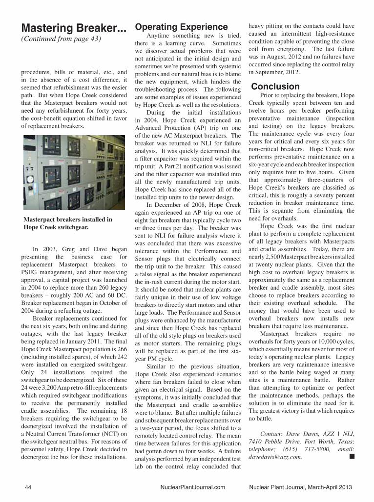
44 NuclearPlantJournal.com Nuclear Plant Journal, March-April 2013
procedures, bills of material, etc., and in the absence of a cost difference, it seemed that refurbishment was the easier path. But when Hope Creek considered that the Masterpact breakers would not need any refurbishment for forty years, the cost-benefi t equation shifted in favor of replacement breakers.
In 2003, Greg and Dave began presenting the business case for replacement Masterpact breakers to PSEG management, and after receiving approval, a capital project was launched in 2004 to replace more than 260 legacy breakers – roughly 200 AC and 60 DC. Breaker replacement began in October of 2004 during a refueling outage.
Breaker replacements continued for the next six years, both online and during outages, with the last legacy breaker being replaced in January 2011. The fi nal Hope Creek Masterpact population is 266 (including installed spares), of which 242 were installed on energized switchgear. Only 24 installations required the switchgear to be deenergized. Six of these 24 were 3,200 Amp retro-fi ll replacements which required switchgear modifi cations to receive the permanently installed cradle assemblies. The remaining 18 breakers requiring the switchgear to be deenergized involved the installation of a Neutral Current Transformer (NCT) on the switchgear neutral bus. For reasons of personnel safety, Hope Creek decided to deenergize the bus for these installations.
Operating ExperienceAnytime something new is tried,
there is a learning curve. Sometimes we discover actual problems that were not anticipated in the initial design and sometimes we’re presented with systemic problems and our natural bias is to blame the new equipment, which hinders the troubleshooting process. The following are some examples of issues experienced by Hope Creek as well as the resolutions.
During the initial installations in 2004, Hope Creek experienced an Advanced Protection (AP) trip on one of the new AC Masterpact breakers. The breaker was returned to NLI for failure analysis. It was quickly determined that a fi lter capacitor was required within the trip unit. A Part 21 notifi cation was issued and the fi lter capacitor was installed into all the newly manufactured trip units. Hope Creek has since replaced all of the installed trip units to the newer design.
In December of 2008, Hope Creek again experienced an AP trip on one of eight fan breakers that typically cycle two or three times per day. The breaker was sent to NLI for failure analysis where it was concluded that there was excessive tolerance within the Performance and Sensor plugs that electrically connect the trip unit to the breaker. This caused a false signal as the breaker experienced the in-rush current during the motor start. It should be noted that nuclear plants are fairly unique in their use of low voltage breakers to directly start motors and other large loads. The Performance and Sensor plugs were enhanced by the manufacturer and since then Hope Creek has replaced all of the old style plugs on breakers used as motor starters. The remaining plugs will be replaced as part of the fi rst six-year PM cycle.
Similar to the previous situation, Hope Creek also experienced scenarios where fan breakers failed to close when given an electrical signal. Based on the symptoms, it was initially concluded that the Masterpact and cradle assemblies were to blame. But after multiple failures and subsequent breaker replacements over a two-year period, the focus shifted to a remotely located control relay. The mean time between failures for this application had gotten down to four weeks. A failure analysis performed by an independent test lab on the control relay concluded that
heavy pitting on the contacts could have caused an intermittent high-resistance condition capable of preventing the close coil from energizing. The last failure was in August, 2012 and no failures have occurred since replacing the control relay in September, 2012.
ConclusionPrior to replacing the breakers, Hope
Creek typically spent between ten and twelve hours per breaker performing preventative maintenance (inspection and testing) on the legacy breakers. The maintenance cycle was every four years for critical and every six years for non-critical breakers. Hope Creek now performs preventative maintenance on a six-year cycle and each breaker inspection only requires four to fi ve hours. Given that approximately three-quarters of Hope Creek’s breakers are classifi ed as critical, this is roughly a seventy percent reduction in breaker maintenance time. This is separate from eliminating the need for overhauls.
Hope Creek was the fi rst nuclear plant to perform a complete replacement of all legacy breakers with Masterpacts and cradle assemblies. Today, there are nearly 2,500 Masterpact breakers installed at twenty nuclear plants. Given that the high cost to overhaul legacy breakers is approximately the same as a replacement breaker and cradle assembly, most sites choose to replace breakers according to their existing overhaul schedule. The money that would have been used to overhaul breakers now installs new breakers that require less maintenance.
Masterpact breakers require no overhauls for forty years or 10,000 cycles, which essentially means never for most of today’s operating nuclear plants. Legacy breakers are very maintenance intensive and so the battle being waged at many sites is a maintenance battle. Rather than attempting to optimize or perfect the maintenance methods, perhaps the solution is to eliminate the need for it. The greatest victory is that which requires no battle.
Contact: Dave Davis, AZZ | NLI, 7410 Pebble Drive, Fort Worth, Texas; telephone; (615) 717-5800, email: [email protected]. �
Masterpact breakers installed in Hope Creek switchgear.
Mastering Breaker...(Continued from page 43)
MASTERPACT® IS A REGISTERED TRADEMARK OF SQUARE D/SCHNEIDER ELECTRIC
Maybe you can do this during
the next outage.
Outages require negotiating one hazard after another. But you can avoid a lot of problems just by replacing your low
voltage breakers with Masterpact®. These breakers are easy
to install, extremely reliable and virtually maintenance free—
for 40 years! And while you may not actually be able to take the
day off for golf during an outage, the time saved on breaker
maintenance or by eliminating overhauls can be put to much
better use. The Masterpact® is just one of the many innovative
products and services that NLI provides that will eliminate a variety
of hazards and dramatically improve your score.
© COPYRIGHT 2013 AZZ | NLI
Next time your facility is faced with equipment and maintenancechallenges, call NLI. We’re your single source.

A Solution for Aging BWR Plants: Jet Pump Anti-Vibration SolutionBy Bret Nelson, GE Hitachi Nuclear Energy.
Bret NelsonBret Nelson has over 25 years’ experience working in nuclear power, including construction, testing, and engineering operations support at the Perry Nuclear Power Plant in northeast Ohio, and as a consultant to the nuclear industry. He has been with GE Hitachi for seven years, serving the past three years as manager of the Reactor Services Hardware Design team. Bret holds a BSME from Cleveland State University and a JD from the Capital University School of Law in Ohio.
Jet Pump related issues, such as wear and vibration, have increased in frequency and severity since the 1980s due to component aging and increased plant operational performance challenges. As a result, BWR-4 and BWR-5 Jet Pump assemblies are increasingly prone to developing gaps between the restrainer bracket set screws and the inlet mixer, excessive wear of the main wedge and rod, restrainer bracket damage, and slip joint fl ow-induced vibrations.
During the spring 2013 refueling outage season, GE Hitachi Nuclear Energy (GEH) has begun installing its innovative Jet Pump Anti-Vibration Solution (JP AVS) that has been tested by the Electrical Power Research Institute (EPRI) to fi x these diffi cult problems and provide upgrades for BWR 4 and 5 plants. The JP AVS, coupled with GEH Slip Joint Clamps, will offer a complete solution to all Jet Pump vibration problems by addressing the cause rather than the symptoms of fl ow induced vibration (FIV).
GE Hitachi is the fi rst to market this innovative product, following a comprehensive and concerted effort, through causal analysis and testing, to fi nd a robust and effective solution to increasing wear among jet pumps in the BWR fl eet.
As a result of the increasing FIV, the existing set screw and main wedge system for maintaining the required three-point contact at the Jet Pump restrainer bracket was found to be insuffi cient for
susceptible Jet Pumps. To eliminate this problem, the new anti-vibration upgrade at the restrainer bracket takes advantage
of hydraulic loads, while positively maintaining the required three-point contact.
The new anti-vibration upgrade at the restrainer bracket has undergone successful full-scale testing at the new EPRI facility in Princeton, New Jersey as well as thorough vibration testing at Wyle Labs in Huntsville, Alabama.
As a result of the EPRI testing, the new GEH anti-vibration upgrade at the restrainer bracket was demonstrated to preclude slip joint leakage instability for most plant operating conditions, even with a severe slip joint gap. Test results by EPRI show that with application of the restrainer bracket upgrade and slip joint clamp, initiation of slip joint leakage instability could only occur in areas that are well outside any plant operating region. “We are pleased to offer this innovative and tested solution to our customers,” said Manny Klein, Jet Pump Modifi cations Product Line Leader with GE Hitachi.
Contact: Emanuel (Manny) Klein, GE Hitachi Nuclear Energy, telephone: (910) 819-6427, email: [email protected], and Bret Nelson, GE Hitachi Nuclear Energy, email: [email protected] �
JP AVS installed on the Jet Pump Restrainer Bracket.
JP AVS Installed on Jet Pump Restrainer Bracket showing 3 Point Contact (Top-Down View).
46 NuclearPlantJournal.com Nuclear Plant Journal, March-April 2013

Nuclear Plant Journal, March-April 2013 NuclearPlantJournal.com 47
Meeting & Training Calendar 1. Used Fuel Management Conference,
May 7-9, 2013, Renaissance Vinoy, St. Petersburg, Florida. Contact: Linda Wells, Nuclear Energy Institute, telephone: (202) 739-8039, email: [email protected].
2. North American Young Generation
in Nuclear, May 12-14, 2013, Grand Hyatt, Washington, D.C. Contact: Linda Wells, Nuclear Energy Institute, telephone: (202) 739-8039, email: [email protected].
3. Nuclear-101, May 13-14, 2013, McMaster University, Hamilton, Ontario, Canada. Contact: Canadian Nuclear Society, telephone: (416) 977-7620, email: [email protected].
4. Annual Nuclear Industry Conference and Nuclear Supplier Expo: Nuclear Energy Assembly, May 13-15, 2013, Grand Hyatt Washington, Washington, D.C. Contact: Linda Wells, Nuclear Energy Institute, telephone: (202) 739-8039, email: [email protected].
5. Annual Meeting on Nuclear Technology, May 14-16, 2013, Berlin, Germany. Contact: German Nuclear Society, website: kerntechnik.info/home.
6. 9th Annual China Nuclear Energy Congress, May 15-17, 2013, Beijing, China. Contact: telephone: 86 21 68407631, fax: 86 21 63931899, email: [email protected].
7. International Experts’ Meeting on Human and Organizational Factors in Nuclear Safety in the Light of the Accident at the Fukushima Daiichi Nuclear Power Plant, May 21-24, 2013, Vienna, Austria. Contact: International Atomic Energy Agency, telephone: 43 1 2600, fax: 43 1 2600 2007, email: offi [email protected].
8. Platts 4th Annual Small Modular Reactors, May 29-30, 2013, Mandarin Oriental Hotel, Washington, D.C. Contact: telephone: (866) 355-2930, fax: (781) 430-2101, email: [email protected].
9. Power-Gen Europe, June 4-6, 2013, Vienna, Austria. Contact: Emily Pryor, Pennwell, telephone: 44 1992 656 614, email: [email protected].
10. Emergency Preparedness Training Course, June 9-11, 2013, Hyatt Regency Baltimore, Baltimore, Maryland. Contact: Linda Wells, Nuclear Energy Institute, telephone: (202) 739-8039, email: [email protected].
11. FLEX Workshop, June 11, 2013, Hyatt Regency Baltimore, Baltimore, Maryland. Contact: Linda Wells, Nuclear Energy Institute, telephone: (202) 739-8039, email: [email protected].
12. 2013 ASME Annual Meeting, June 21-26, 2013, JW Marriott Indianapolis, Indiana. Contact: telephone: (800) 843-2763, email: [email protected].
13. International Forum ATOMEXPO 2013, June 26-28, 2013, St. Petersburg, Russia. Contact: telephone: 7 495 66 33 821, fax: 7 495 66 33 820, email: [email protected].
14. UniTech’s R3 Nuclear Workshop, June 26-28, 2013, Intercontinental Hotel, Chicago, Illinois. Contact: Gregg Johnstone, telephone: (413) 543-6911, website: www.regonline.com/UniTechR3workshop
15. U.S. Women in Nuclear 2013, July 21-24, 2013, Swissotel Chicago, Chicago, Illinois. Contact: Linda Wells, Nuclear Energy Institute, telephone: (202) 739-8039, email: [email protected].
16. Radiation Protection Forum, July 28-31, 2013, The Westin Riverwalk, San Antonio, Texas. Contact: Linda Wells, Nuclear Energy Institute, telephone: (202) 739-8039, email: [email protected].
17. International Conference on Nuclear Engineering (ICONE), July 29-August 2, 2013, Chendu, China. Contact: Erin Dolan, ASME International, telephone: (212) 591-7123, fax: (212) 591-7856, email: [email protected].
18. Nuclear Fuel Supply Forum, July 30, 2013, The Westin Georgetown Hotel, Washington, D. C. Contact: Linda Wells, Nuclear Energy Institute, telephone: (202) 739-8039, email: [email protected].
19. Utility Working Conference and Vendor Technology Expo, August 11-14, 2013, Westin Diplomat, Hollywood, Florida. Contact: American Nuclear Society, telephone: (708) 579-8316, email: [email protected].
20. 16th International Conference on Environmental Degradation of Materials in Nuclear Power Systems- Water Reactors, August 11-15, 2013, Asheville, North Carolina. Contact: NACE International, telephone: (281) 228-6200-8316, fax: (281) 228-6300, email:fi [email protected].
21. The International Symposium on Packaging and Transportation of Radioactive Materials (PATRAM). August 18-23, 2013, Hilton San Francisco Union Square, San Francisco, California. Contact: Institute of Nuclear Materials Management, telephone: (847) 480-9573, email: [email protected].
22. World Nuclear Assocation Annual Symposium 2013, September 11-13, 2013, Central Hall Westminster, London. Contact: telephone: 44 20 7451 1520, fax: 44 20 7839 1501. �

48 NuclearPlantJournal.com Nuclear Plant Journal, March-April 2013
Vogtle First Nuclear ConcreteBy Georiga Power.
On March 14, 2013, Georgia Power completed the placement of basemat structural concrete for the nuclear island at its Vogtle Unit 3 nuclear expansion site, a signifi cant achievement in the building of the fi rst new nuclear units in the United States in 30 years. Vogtle Units 3 and 4 will each utilize the Westinghouse AP1000 reactor.
“This historic moment marks yet another important milestone of the Vogtle expansion project and refl ects the tremendous progress we’ve made at
the site,” said Georgia Power Nuclear Development Executive Vice President Buzz Miller. “We are very proud of this accomplishment, and of all the hard work and collaboration that went into making it happen. This was a team effort that included Georgia Power, Southern
Nuclear, CB&I, Westinghouse Electric Company and our co-owners - Oglethorpe Power Corporation, the Municipal Electric Authority of Georgia and Dalton Utilities.”
Georgia Power is building Vogtle units 3 and 4, near Waynesboro, Georgia.
The fi rst components for erecting the Unit 3 containment vessel are completed and staged for installation once the basemat concrete has cured, including the cradle and the Unit 3 containment vessel bottom head.
While maintaining focus on safety, quality and compliance, the basemat concrete placement was completed in approximately 41 hours. The placement at Vogtle Unit 3 encompassed approximately 7,000 cubic yards of concrete, which will serve as the foundation for all of the nuclear island structures, including
the containment vessel and the shield building. It covered an area approximately 250 feet long and 160 feet wide at its widest point, and the concrete measured six feet in thickness.
Vogtle Unit 3 construction progress – turbine and nuclear island in the foreground, and the cooling tower, containment vessel bottom head and CR10 cradle assembly in the background.
The construction of Vogtle 3 and 4 is the largest job-producing project in Georgia, employing approximately 5,000 people during peak construction and creating 800 permanent jobs when the plant begins operating. Once complete, the new units will produce enough electricity to power 500,000 Georgia homes and businesses.
Unit 3 is scheduled to go on line in 2017, and Unit 4 will follow in 2018.
The facility provides at least $4 billion more value to customers than the next best available technology, including natural gas generation. Georgia Power is in a position to provide customers with up to $2 billion in potential benefi ts in the form of savings related to recovering fi nancing costs during construction, DOE loan guarantees, production tax credits, lower-than-forecast interest rates and lower-than-forecast commodity costs.
Southern Nuclear, a subsidiary of Southern Company, is overseeing construction and will operate the two new 1,100-megawatt AP1000 units for Georgia Power and co-owners Oglethorpe Power Corporation, the Municipal Electric Authority of Georgia and Dalton Utilities. Georgia Power owns 45.7 percent of the new units.
Georgia Power is the largest subsidiary of Southern Company, one of the nation’s largest generators of electricity. The company is an investor-owned, tax-paying utility with rates below the national average. Georgia Power serves 2.4 million customers in all but four of Georgia’s 159 counties.
Contact: Mark Williams, Georgia Power, telephone: (404) 506-7676, webstie: www.georgiapower.com. �

Nuclear Plant Journal now offers digital versions of the Journal, enabling readers: • Direct Vendor & Author Contact• Mobile Device Access• “Flip-page” Functionality• Multi Issue Accessibility• Offl ine Access
For additional details, please contact Anu Agnihotri via telephone at (630) 352-3686 or email [email protected]. You may also visit:

50 NuclearPlantJournal.com Nuclear Plant Journal, March-April 2013
NPJ Advertiser Web DirectoryAREVA NP, Inc.www.areva.com
AZZ | NLIwww.azz.com/nli
Bechtel Powerwww.bechtel.com
Bigge Crane and Riggingwww.bigge.com
CB&Iwww.CBI.com
Diakontwww.diakont.com
E. H. Wachs Co.www.ehwachs.com
Energy Steel & Supply Co.www.energysteel.com
Fairbanks Morse Enginewww.fairbanksmorsenuclear.com
Fauske & Associates, LLCwww.fauske.com
GE Hitachi Nuclear Energyge-energy.com/nuclear
HF Controlswww.doosan.com
HukariAscendentwww.hukari.com
ORTECwww.ORTEC-online.com
Quest Integrity Groupwww.questintegrity.com/
Rolls-Roycewww.rolls-royce.com
Seal Masterwww.sealmaster.com
Structural Integrity Associates, Inc.www.structint.com
Tri Tool Inc.www.tritool.com
Westinghouse Electric Company LLCwww.westinghousenuclear.com
Summer First Nuclear ConcreteBy South Carolina Electric & Gas Company.
The PourSouth Carolina Electric & Gas
Company (SCE&G), principal subsidiary of SCANA Corporation, completed on March 11, 2013, placement of the nuclear island basemat for V.C. Summer Unit 2 in Fairfi eld County, South Carolina. This major milestone is the fi rst new construction nuclear concrete to be poured in the U.S. in three decades. V.C. Summer Units 2 and 3 will each utilize the Westinghouse AP1000 PWR.
“This is an exciting achievement for SCE&G, Santee Cooper, CB&I, Westinghouse Electric Company, and others who support our new nuclear project,” said Kevin Marsh, chairman and CEO of SCANA. “We recognize the signifi cance of this event and appreciate the strong commitment to safety and collaboration demonstrated by all involved in reaching this milestone.”
Lonnie Carter, president and CEO of Santee Cooper, which co-owns V.C. Summer, said, “This is a tremendous day for South Carolina as we work with SCANA to deliver new nuclear generation that will help ensure reliable, affordable electricity for decades to come. We’ve
come to this point through the diligent and conscientious attention to task by everyone involved, from our crews to the Nuclear Regulatory Commission.”
The basemat provides a foundation for the containment and auxiliary buildings that are within the nuclear island. Measuring 6 feet in thickness, the basemat required approximately 7,000 cubic yards of concrete to cover an area about 250 feet long and 160 feet at its widest section. Completed about 10 a.m. on March 11, 2013, this 51.5-hour continuous pour of concrete covered a surface totaling 32,000 square feet.
About 1,550 workers are currently involved in constructing two new reactors at V.C. Summer, where the existing Unit 1 has operated safely and reliably for 30 years. The new nuclear project will peak at about 3,000 workers over the course of three to four years. The two 1,117-megawatt units will add 600 to 800 permanent jobs and bring SCE&G’s portfolio to 60 percent non-emitting sources when they start generating electricity in 2017 and 2018, respectively.
V.C. SummerV.C. Summer Nuclear Station • (operating unit) is currently a single unit, pressurized water reactor plant located approximately 30 miles northwest of Columbia in Jenkinsville, South Carolina. The plant began commercial operation on January 1, 1984.The nuclear station is named after the • late Virgil Summer, former SCANA Chairman and CEO.Summer Station is capable of • generating 1,000 megawatts of electricity, roughly 21 percent of SCE&G’s electricity.In 2004, the NRC granted Summer • Station a 20-year extension to its operating license, allowing the plant to operate through 2042.V.C. Summer employs approximately • 825 employees.
Contact: Rhonda O’Banion, telephone: (800) 562-9308, email: [email protected], website: http://www.sceg.com/en/about-sceg/power-plants/ �
Construction teams placed concrete using pumps into the V.C. Summer Unit 2 rebar structure that forms the basemat of the new AP1000®.
WE
ST
ING
HO
US
E E
LE
CT
RIC
CO
MP
AN
Y L
LC
ONE SMALL WESTINGHOUSE REACTOR
Another giant step by the true leader in commercial nuclear energy
Westinghouse, the world leader in the development, licensing and deployment of commercial nuclear energy plants, is again leading the industry, this time with a 225 MWe integrated pressurized water reactor that can generate electricity for a residential community of 180,000 homes without emitting any greenhouse gases.
And unlike other designs, the Westinghouse Small Modular Reactor (SMR) is an outgrowth of proven, land-based nuclear reactor technology that takes safety, reliability and constructability to unsurpassed levels.
To make this exciting new reactor a reality, Westinghouse, with the full support and backing of its majority owner Toshiba Corporation, is working with a distinguished group of partners, notably Ameren Missouri, the Association of Missouri Electric Cooperatives, Associated Electric Cooperative, Inc., The Empire District Electric Company, Kansas City Power & Light Company and the Missouri Public Utility Alliance.
Proud of our track record of success, but always looking to the future, Westinghouse nuclear technology will help provide future generations with safe, clean and reliable electricity.
Check us out at www.westinghousenuclear.com

CIVILGOVERNMENT SERVICESMINING & METALSOIL, GAS & CHEMICALSPOWER
Bechtel is among the most respected engineering, procurement, and construction companies in the world. We stand apart for the ability to get the job done right−no matter how big, how complex, or how remote. Since 1898, we have completed more than 23,000 projects in 140 nations on all seven continents.
Building the World’s Energy Future