1.25 mm f-p connector (board to board) sheets/tyco electonics...2.1 te 規格 a. 411-5546...
TRANSCRIPT
108108108108----5246524652465246
Product SpecificationProduct SpecificationProduct SpecificationProduct Specification
製品規格製品規格製品規格製品規格
06 JUL ’2010 Rev.L
タイコ エレクトロニクス ジャパン合同株式会社 (〒213-8535 川崎市高津区久本 3-5-8) 1 of 21 Tyco Electronics Japan G.K. (3-5-8 Hisamoto Takatsu-ku Kawasaki, 213-8535) この文書の改版の確認は本社、支店へお問い合わせください。 This document is subject to change. Call local TE for the latest revision. © Copyright 2010 by Tyco Electronics Japan G.K. All rights reserved. * : 商標 Trademark
1.25 mm F-P connector (Board To Board)
1. 適用範囲
1.1 内容
本規格は基板対基板接続用コネクタで、1.25F-Pコネク
タの製品性能、試験方法、品質保証の必要条件を規定
している。
適用製品名と型番はFig.1-1,1-2,1-3,1-4の通りであ
る。
1. Scope :
1.1 Contents
This specification covers the requirements for
product performance, test methods and quality
assurance provisions of AMP 1.25 F-P Connector
(Board To Board).
Applicable product descriptions and part numbers are
as shown in Fig.1-1,1-2,1-3,1-4.
2. 参考規格類
以下規格類は本規格中で規定する範囲内に於いて、
本規格の一部を構成する。万一本規格と製品図面の
間に不一致が生じた時は、製品図面を優先して適用
すること。万一本規格と参考規格類の間に不一致が
生じた時は、本規格を優先して適用すること。
2. Applicable Documents:
The following documents form a part of this
specification to the extent specified herein. In the
event of conflict between the requirements of this
specification and the product drawing, the product
drawing shall take precedence. In the event of
conflict between the requirements of this
specification and the referenced documents, this
specification shall take precedence.
2.1 TE 規格
A. 411-5546 :取扱説明書
B. 501-5205 :試験報告書
2.1 TE Specifications :
A. 411-5546 Instruction Sheet
B. 501-5205 Test Report
2.2 民間団体規格
A. MIL-STD-202 : 電子電気部品の試験方法
2.2 Commercial Standards and pecifications :
A. MIL-STD-202 : Test Methods for Electronic and
Electrical Component Parts.
3. 一般必要条件 3. Requirements :
3.1 設計と構造
製品は該当製品図面に規定された設計、構造、物理
的寸法をもって製造されていること。
3.1 Design and Construction :
Product shall be of the design, construction and
physical dimensions specified on the applicable
product drawing.
Product Specification 108-5246
Rev. L 2 of 21
3.2 材 料
A. リセ・コンタクト:
リン青銅
・錫めっき品
ニッケル下地めっき( 0.5μm以上)
錫めっき仕上げ(0.2μm以上)
・金めっき品
全面ニッケル下地めっき(1μm以上)
接触部:
パラジウムニッケルめっき
仕上げ(0.4μm以上)
金めっき仕上げ(0.05μm以上)
はんだ付け部:
金めっき仕上げ (0.05μm以上)
B. ポスト:
黄銅 0.5 DIA
・ 錫めっき品
銅下地めっき(0.5μm以上)
錫めっき済(0.8μm以上)
・ 金めっき品
ニッケル下地めっき(1μm以上)
金めっき仕上げ(0.2μm以上)
C. リセ・ハウジング
PPS樹脂(UL94 V-0)…黒色
D. ヘッダー・ハウジング
PPS樹脂(UL94 V-0)…黒色
E. スペーサー・ハウジング
6/6ナイロン樹脂(UL94 V-0)…黒色
F. リレー・ヘッダー・ハウジング
6/6ナイロン樹脂(UL94 V-0)…黒色
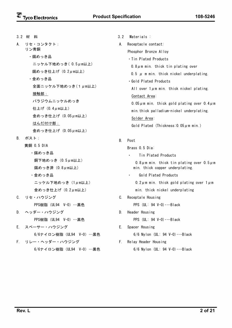
3.2 Materials :
A. Receptacle contact:
Phosphor Bronze Alloy
・Tin Plated Products
0.8μm min. thick tin plating over
0.5 μ m min. thick nickel underplating.
・Gold Plated Products
All over 1μm min. thick nickel plating.
Contact Area:
0.05μm min. thick gold plating over 0.4μm
min.thick palladium-nickel underplating.
Solder Area:
Gold Plated (Thickness:0.05μm min.)
B. Post
Brass 0.5 Dia:
・ Tin Plated Products
0.8μm min. thick tin plating over 0.5μm
min. thick copper underplating.
・ Gold Plated Products
0.2μm min. thick gold plating over 1μm
min. thick nickel underplating
C. Receptale Housing
PPS (UL: 94 V-0)・…Black
D. Header Housing
PPS (UL: 94 V-0)・…Black
E. Spacer Housing
6/6 Nylon (UL: 94 V-0)・…Black
F. Relay Header Housing
6/6 Nylon (UL: 94 V-0)・…Black

Product Specification 108-5246
Rev. L 3 of 21
3.3 定 格
A. 定格電圧 50 V AC/DC
B. 定格電流 0.5A
C. 使用温度範囲 -30 °C~ +105 ℃
(但し、温度の上限には負荷電流
によって生じる温度上昇を含む)
3.3 Ratings :
A. Voltage Rating: 50 V AC/DC
B. Current Rating: 0.5A
C. Temperature Rating :-30 °C to +105 °C
The upper limit of the temperature includes the
temperature rising resulted by the energized
electrical current.
3.4 性能必要条件と試験方法
製品は Fig.2 に規定された電気的、機械的、及び耐
環境的性能必要条件に合致するよう設計されている
こと。試験は特別に規定されない限り室温下で行わ
れること。
3.4 Performance Requirements and Test
Descriptions :
The product shall be designed to meet the
electrical, mechanical and environmental
performance requirements specified in Fig. 2.
All tests shall be performed in the room
temperature, unless otherwise specified.

Product Specification 108-5246
Rev. L 4 of 21
3.5 性能必要条件と試験方法の要約
3.5 Test Requirements and Procedures Summary:
項目 試験項目 規 格 値 試 験 方 法
3.5.1 製品の確認 製品図面の必要条件に合致し
ていること。
目視により、コネクタの機能上支
障をきたす損傷を検査する。
Para. Test Items Requirements Procedures
3.5.1 Examination of Product Meets requirements of product
drawing.
Visual inspection
No physical damage
電 気 的 性 能
Electrical Requirements
3.5.2 総合抵抗
(ローレベル)
10 mΩ 以下(初期値)
20 mΩ 以下(試験後)
ハウジングに組み込まれ嵌合し
たコンタクトを開路電圧20 mV以
下、閉路電流10 mA以下の条件で
測定する。
Fig.6参照。
3.5.2 Termination Resistance
(Low Level)
10 mΩMax. (Initial)
20 mΩMax. (Final)
Subject mated contacts ssembled
in housing to 20 mV max. open
circuit at 10 mA max.. Fig.6.
3.5.3 絶縁抵抗 500 MΩ 以上 (初期値)
100 MΩ 以上 (終期値)
嵌合したコネクタの隣接コンタ
クト間で測定。
MIL-STD-202、試験法302 条件A
100 V DC±10% 1分間
3.5.3 Insulation Resistance 500 MΩMin. (Initial)
100 MΩMin. (Final)
Measure by appling test
potential between the adjacent
contacts, and between the
conacts and ground in the mated
connectors.
MIL-STD-202, METHOD 302
Condition A,
100 V DC±10%, I minute
3.5.4 耐電圧 0.5k V ACの試験電圧(1分間保
持)に耐えること。
電流漏洩は0.5mA以下
嵌合したコネクタ・アセンブリの
隣接コンタクト間で測定。
MIL-STD-202、試験法301
3.5.4 Dielectric withstanding
Voltage
Connector must withstand test
potential of 0.5K V AC for 1
minute. Current leakage must
be 0.5 mA Max.
Measure by appling test
potential between the adjacent
contacts, and between the
conacts and ground in the mated
connectors.
MIL-STD-202,METHOD 301
Fig.2 (続き)
Fig.2 (To be continued)

Product Specification 108-5246
Rev. L 5 of 21
項目 試験項目 規 格 値 試 験 方 法
Para. Test Items Requirements Procedures
3.5.5 温度上昇対電流 規定電流を通電して、温度上昇
は30 °C以下
通電による温度上昇を測定する
こと。
3.5.5 Temperature Rising VS
Current
30 °C Max. under loaded
rating current.
Measure temperature rising by
energized current.
環 境 的 性 能
Environmental Requirements
3.5.6 耐湿性(定常状態) 総合抵抗(ローレベル)
20mΩ最大(試験後)
絶縁抵抗:100MΩ以上(終期値)
嵌合したコネクタを相対湿度90
~95%、温度40±2℃の定常状態
に500時間さらすこと。
MIL-STD202、試験法103,条件C
3.5.6 Humidity, Steady State Termination Resistance
(Low Level)(Final)
20 mΩ max.
Insulation Resistance(Final)
100MΩ max.
Subject mated connetors to
steady state humidity at 40℃
and 90-95% R.H. for 500 hours.
MIL-STD-202, METHOD 103,
Condition C.
3.5.7 耐熱性 総合抵抗(ローレベル)
20 mΩ 最大(試験後)
嵌合したコネクタを温度85±2°C
の試験環境下に500時間さらすこ
と。
MIL-STD-202、試験法108条件C
3.5.7 Heat Resistivity Termination Resistance
(Low level)(Final)
20 mΩ Max.
Subject mated connectors to
heat resistivity at 85±2°Cfor
500 hours,per
MIL-STD-202,METHOD 108,
Condition C
3.5.8 熱衝撃 総合抵抗(ローレベル)
20 mΩ 最大(試験後)
嵌合したコネクタを
-55 °C / 30 分、+85 °C / 30 分
を 1 サイクルとし、25サイクル
さらすこと。
MIL-STD-202、試験法107条件A-1
3.5.8 Thermal Shock Termination Resistance
(Low level)(Final)
20 mΩ Max.
Subject mated connectors to 25
cycles between -55°C and +85 °C
for 30 minutes each.
MIL-STD-202,METHOD 107,
Condition A-1
Fig.2 (続き)
Fig.2(To be continued)
Product Specification 108-5246
Rev. L 6 of 21
項目 試験項目 規 格 値 試 験 方 法
Para. Test Items Requirements Procedures
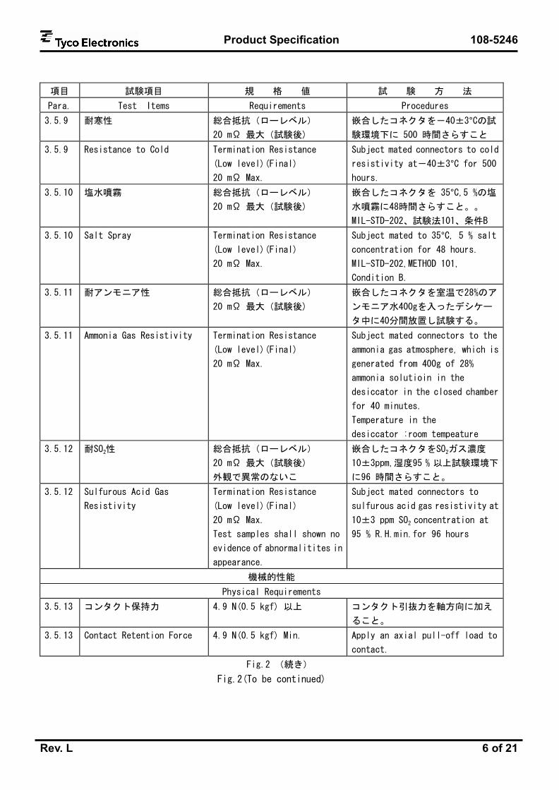
3.5.9 耐寒性 総合抵抗(ローレベル)
20 mΩ 最大(試験後)
嵌合したコネクタを-40±3°Cの試
験環境下に 500 時間さらすこと
3.5.9 Resistance to Cold Termination Resistance
(Low level)(Final)
20 mΩ Max.
Subject mated connectors to cold
resistivity at-40±3°C for 500
hours.
3.5.10 塩水噴霧 総合抵抗(ローレベル)
20 mΩ 最大(試験後)
嵌合したコネクタを 35°C,5 %の塩
水噴霧に48時間さらすこと。。
MIL-STD-202、試験法101、条件B
3.5.10 Salt Spray Termination Resistance
(Low level)(Final)
20 mΩ Max.
Subject mated to 35°C, 5 % salt
concentration for 48 hours.
MIL-STD-202,METHOD 101,
Condition B.
3.5.11 耐アンモニア性 総合抵抗(ローレベル)
20 mΩ 最大(試験後)
嵌合したコネクタを室温で28%のア
ンモニア水400gを入ったデシケー
タ中に40分間放置し試験する。
3.5.11 Ammonia Gas Resistivity Termination Resistance
(Low level)(Final)
20 mΩ Max.
Subject mated connectors to the
ammonia gas atmosphere, which is
generated from 400g of 28%
ammonia solutioin in the
desiccator in the closed chamber
for 40 minutes.
Temperature in the
desiccator :room tempeature
3.5.12 耐SO2性
総合抵抗(ローレベル)
20 mΩ 最大(試験後)
外観で異常のないこ
嵌合したコネクタをSO2ガス濃度
10±3ppm,湿度95 % 以上試験環境下
に96 時間さらすこと。
3.5.12 Sulfurous Acid Gas
Resistivity
Termination Resistance
(Low level)(Final)
20 mΩ Max.
Test samples shall shown no
evidence of abnormalitites in
appearance.
Subject mated connectors to
sulfurous acid gas resistivity at
10±3 ppm SO2 concentration at
95 % R.H.min.for 96 hours
機械的性能
Physical Requirements
3.5.13 コンタクト保持力 4.9 N(0.5 kgf) 以上 コンタクト引抜力を軸方向に加え
ること。
3.5.13 Contact Retention Force 4.9 N(0.5 kgf) Min. Apply an axial pull-off load to
contact.
Fig.2 (続き)
Fig.2(To be continued)

Product Specification 108-5246
Rev. L 7 of 21
項目 試験項目 規 格 値 試 験 方 法
Para. Test Items Requirements Procedures
3.5.14 コネクタ挿入力、引抜力 Fig.4,Fig.5 参照 コンタクト・アセンブリを毎分
20mmの速度で30回挿入、引抜す
る。この時の挿入力及び引抜力を
測定する。
3.5.14 Mating /Unmating Force Fig.4, Fig.5 Measure the mating force and
the unmating force when
receptacle assembly and post
header assembly are mated and
unmated for 30 cycles at a rate
of 20 mm a minute.
3.5.15 耐久性
(繰り返し挿抜)
総合抵抗(ローレベル):
20 mΩ 最大(試験後)
コネクタ・アセンブリを30サイク
ル挿入・引抜を繰り返す。.
3.5.15 Durability
(Repeated Mate / Unmating)
Termination resistance
(low level)(Final)
20 mΩ Max.
Mate and unmate connectors for
30 cycles.
3.5.16 振動
正弦波
低周波
振動中 1 μsec. を越える不連
続導通を生じないこと。
総合抵抗(ローレベル):
20 mΩ 最大(試験後)
嵌合したコネクタに 1.52 mm の
振幅で、10-55-10 Hz に毎分 1 サ
イクルの割合で変化する掃引振
動を直交する三方向軸に 2 時間
ずつ与えること。
MIL-STD-202、試験法201
尚、嵌合後のコネクタはFig.7に
示す様に固定して行う。
3.5.16 Vibration
Sinusoidal
Low Frequency
No electrical discontinuity
greater than 1 μsec. shall
occur.
Termination resistance
(low level)(Final)
20 mΩ Max.
Subject mated connectors to
10-55-10 Hz traversed in 1
minute at 1.52 mm amplitude 2
hours each of 3 mutually
perpendicular planes.
MIL-STD-202,METHOD 201
The clamping manner shall be in
accordance with Fig. 7, after
mating the connectors.
Fig.2 (続き)
Fig.2(To be continued)

Product Specification 108-5246
Rev. L 8 of 21
項目 試験項目 規 格 値 試 験 方 法
Para. Test Items Requirements Procedures
3.5.17 微加振動
(ハンマー衝撃)
加振中 1μsecをこえる不連続
導通を生じないこと。
総合抵抗(ローレベル):
20 mΩ 最大(試験後)
嵌合したコネクタをFig.8に示す
条件で10000回加振し、Fig.9に示
す測定回路により印加電圧 DC
10V,1mAの試験電流を通電させた
状態で試験を行い、加振中の抵抗
の変動をモニターする。
尚、嵌合後のコネクタはFig.7に
示す様に固定して行う。
3.5.17 Hammerring Shocks No electrical discontinuity
greater than 1μsec.shall
occur.
Termination resistance
(low level)(Final)
20 mΩ Max.
Subject mated connectors on PCB
as shown in Fig.7,Under 10000
cycles of repeated hammering
shocks of the condition as
shown in Fig.8,with the test
current of 1mA at 10VDC applied
to the circuit as shown in
Fig.9.During the test, the
circuit shall be monitored for
fluctuation of electrical
resistance.
The clamping manner shall be in
accordance with Fig.7 after
mating the connectors.
3.5.18 衝撃 衝撃により1 μsec. を越える
不連続導通を生じないこと。
総合抵抗(ローレベル):
20 mΩ 最大(試験後)
嵌合したコネクタに11m秒間に
50Gの正弦波を生じるような衝撃
を直交する三方向軸の正負方向
に3回まで合計18回与えること
MIL-STD-202、験法213,条件A
尚、嵌合後のコネクタはFig.7に
示す様に固定して行う。
Fig.2 (続き)
Fig.2(To be continued)

Product Specification 108-5246
Rev. L 9 of 21
項目 試験項目 規 格 値 試 験 方 法
Para. Test Items Requirements Procedures
3.5.18 Physical Shock
No electrical discontinuity
greater than 1μsec. shall
occur.
Termination resistance
(low level)(Final)
20 mΩ Max.
Subject mated connectors to 50 G’s
half sine shock pulses of 16
millisecond duration, 3 shocks in
each direction applied along the
3 mutually perpendicular planes
to totally 18 shocks.
MIL-STD-202,METHOD 213
Condition A
The clamping manner shall be in
accordance with Fig.7 after
mating the connectors.
3.5.19 はんだ付け性 供試品を10倍の拡大鏡を用い
て目視検査し、ピンホールまた
は空隙が1つの面積に集中し
たり、全体の面積の5%を越え
ないこと。
はんだ濡れは95 % 以上。
はんだ温度 :240 ± 5 °C
はんだ浸漬時間:3 ± 0.5 秒
使用フラックス:アルファー 100
(非活性ロジンベース)
はんだ(Sn-3.0Ag-0.5Cu)
3.5.19 Solderability
Appearance of the specimen
shall be inspected after the
test with the assistance of a
magnifier capable of giving a
magnification of 10 X . More
than 95% of the tested area of
the contact shall appear
sufficiently working fresh
coverage of wet solder,
without concentration of void
area in one place or whose
total area is not greater than
5% of the tested area.
The soldering tine areas of the
contacts in post header assembly and
receptacle header assembly shall be
tested by immersing in flux.(Alpha
100, non-active rosin base) for 3 to
5 seconds first, then immerse into
soldering tub filled with melted
Sn-3.0Ag-0.5Cu controlled at 240 ±
5 °C for 3±0.5 seconds
Fig.2 (続き)
Fig.2(To be continued)
Product Specification 108-5246
Rev. L 10 of 21
項目 試験項目 規 格 値 試 験 方 法
Para. Test Items Requirements Procedures
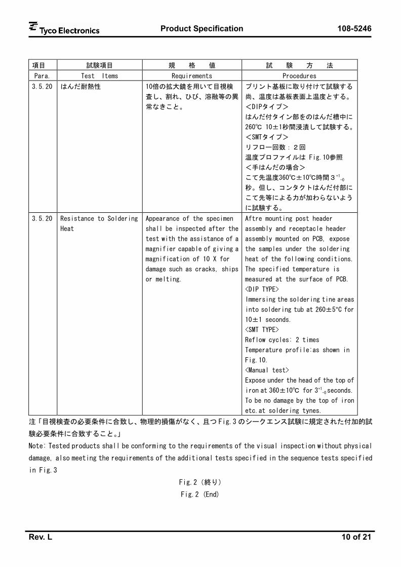
3.5.20 はんだ耐熱性 10倍の拡大鏡を用いて目視検
査し、割れ、ひび、溶融等の異
常なきこと。
プリント基板に取り付けて試験する
尚、温度は基板表面上温度とする。
<DIPタイプ>
はんだ付タイン部をのはんだ槽中に
260℃ 10±1秒間浸漬して試験する。
<SMTタイプ>
リフロー回数:2回
温度プロファイルは Fig.10参照
<手はんだの場合>
こて先温度360℃±10℃時間3+1-0
秒。但し、コンタクトはんだ付部に
こて先等による力が加わらないよう
に試験する。
3.5.20 Resistance to Soldering
Heat
Appearance of the specimen
shall be inspected after the
test with the assistance of a
magnifier capable of giving a
magnification of 10 X for
damage such as cracks, ships
or melting.
Aftre mounting post header
assembly and receptacle header
assembly mounted on PCB, expose
the samples under the soldering
heat of the following conditions.
The specified temperature is
measured at the surface of PCB.
<DIP TYPE>
Immersing the soldering tine areas
into soldering tub at 260±5°C for
10±1 seconds.
<SMT TYPE>
Reflow cycles: 2 times
Temperature profile:as shown in
Fig.10.
<Manual test>
Expose under the head of the top of
iron at 360±10℃ for 3+1-0 seconds.
To be no damage by the top of iron
etc.at soldering tynes.
注「目視検査の必要条件に合致し、物理的損傷がなく、且つ Fig.3 のシークエンス試験に規定された付加的試
験必要条件に合致すること。」
Note: Tested products shall be conforming to the requirements of the visual inspection without physical
damage, also meeting the requirements of the additional tests specified in the sequence tests specified
in Fig.3
Fig.2(終り)
Fig.2 (End)

Product Specification 108-5246
Rev. L 11 of 21
3.6 製品認定試験と製品再確認試験の試験順序
3.6 Product Qualification and Requalification Tests
試験グループ/Test Group(a)
試験項目 Test Examination 1 2 3 4 5 6 7 8 9 10 11 12 13 14 15 16 17
試験順序/Test Sequence (b)
製品の確認 Examination of Product 1,6 1,3 1,5 1,5 1,5 1,5 1,5 1,5 1,5 1 1 1,5 1,5 1,5 1,5 1,3 1.3
総合抵抗 (ローレベル)
Termination Resistance (Low Level)
2,4 2,4 2,4 2,4 2,4 2,4 2,4 2,4 2,4 2,4 2,4
絶縁抵抗 Insulation Resistance 2,5
耐電圧 Dielectric withstanding Voltage
3
温度上昇 Temperature Rising vs Current
2
耐湿性 (定常状態) Humidity (Steady State) 4 3
耐熱性 Heat Resistivity 3
熱衝撃 Thermal Shock 3
耐寒性 Resistance to Cold 3
塩水噴霧 Salt Spray 3
耐アンモニア性 Ammonia Gas Resistivity 3
耐SO2ガス性 SO2 Gas Resistivity 3
コンタクト保持力 Contact Retention Force 2
コネクタ挿抜力 Mating/Unmating Force 2
挿抜耐久性 Durability 3
低周波振動 Vibration (Low Frequency) 3
微加振動
(ハンマー衝撃)
Hammering Shocks 3
耐衝撃性 Physical Shocks 3
はんだ付け性 Solderability 2
はんだ耐熱性 Resistance to Soldering
Heat
2
(a)第4.1.A項参照/See Par.4.1.A
(b)欄内の数字は試験の順序を示す。/Numbers indicate sequence in which the tests are performed.
Fig.3
4. 品質保証条項
4. Quality Assurance Provisions
4.1 製品認定試験
4.1 Qualification Testing
A. 試料の選定
コネクタとコンタクトは該当する取扱説明書に従って作成準備されること。試料は現行の生産システムから無
作為抽出で選定されること。
Product Specification 108-5246
Rev. L 12 of 21
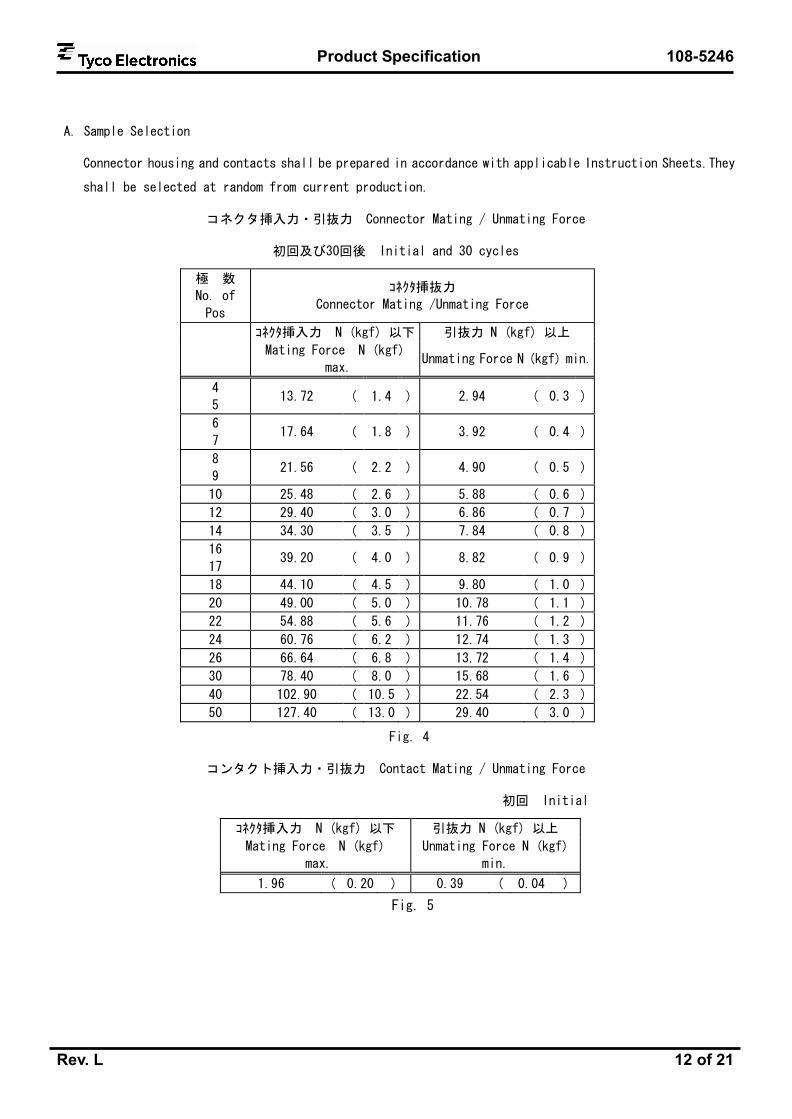
A. Sample Selection
Connector housing and contacts shall be prepared in accordance with applicable Instruction Sheets.They
shall be selected at random from current production.
コネクタ挿入力・引抜力 Connector Mating / Unmating Force
初回及び30回後 Initial and 30 cycles
極 数
No. of
Pos
コネクタ挿抜力
Connector Mating /Unmating Force
コネクタ挿入力 N (kgf) 以下 引抜力 N (kgf) 以上
Mating Force N (kgf)
max. Unmating Force N (kgf) min.
4
5 13.72 ( 1.4 ) 2.94 ( 0.3 )
6
7 17.64 ( 1.8 ) 3.92 ( 0.4 )
8
9 21.56 ( 2.2 ) 4.90 ( 0.5 )
10 25.48 ( 2.6 ) 5.88 ( 0.6 )
12 29.40 ( 3.0 ) 6.86 ( 0.7 )
14 34.30 ( 3.5 ) 7.84 ( 0.8 )
16
17 39.20 ( 4.0 ) 8.82 ( 0.9 )
18 44.10 ( 4.5 ) 9.80 ( 1.0 )
20 49.00 ( 5.0 ) 10.78 ( 1.1 )
22 54.88 ( 5.6 ) 11.76 ( 1.2 )
24 60.76 ( 6.2 ) 12.74 ( 1.3 )
26 66.64 ( 6.8 ) 13.72 ( 1.4 )
30 78.40 ( 8.0 ) 15.68 ( 1.6 )
40 102.90 ( 10.5 ) 22.54 ( 2.3 )
50 127.40 ( 13.0 ) 29.40 ( 3.0 )
Fig. 4
コンタクト挿入力・引抜力 Contact Mating / Unmating Force
初回 Initial
コネクタ挿入力 N (kgf) 以下 引抜力 N (kgf) 以上
Mating Force N (kgf)
max.
Unmating Force N (kgf)
min.
1.96 ( 0.20 ) 0.39 ( 0.04 )
Fig. 5

Product Specification 108-5246
Rev. L 13 of 21
DIP タイプ
DIP TYPE
SMT タイプ
SMT TYPE
1列
仕様
Singl
e R
ow
Typ
e
(P.C.B Vertical Mount Type) 基
板 垂 直 取
付 型
2列仕様
Doubl
e R
ow
Typ
e
Fig.6(1/2) ローレベル総合抵抗測定方法
Fig.6 (1/2) Method of Termination Resistance Measuring

Product Specification 108-5246
Rev. L 14 of 21
DIP タイプ
DIP TYPE
SMT タイプ
SMT TYPE
1列
仕様
Singl
e R
ow
Typ
e
(P.C.B Horizontal Mount Type) 基
板
平
行 取
付
型
2列仕様
Doubl
e R
ow
Typ
e
Fig.6(2/2) ローレベル総合抵抗測定方法
Fig.6 (2/2) Method of Termination Resistance Measuring

Product Specification 108-5246
Rev. L 15 of 21
Fig. 7 コネクタ固定方法
Fig. 7 Method of Connector Mounting for Vibration, Hammering Shock and Physical Shock

Product Specification 108-5246
Rev. L 16 of 21
Fig. 8 微加振動試験方法
Fig.8 Method of Hammering Shock Test

Product Specification 108-5246
Rev. L 17 of 21
Fig. 10 はんだ耐熱性温度プロファイル
Fig.10 Soldering Heat Resistance Temperature Profile
Fig. 9 抵抗変動モニター回路
Fig.9 Circuit of Monitoring
Resistance

Product Specification 108-5246
Rev. L 18 of 21
錫めっき製品
Tin-Lead Products
[1列仕様] Fig.1-1
[Single Row] Fig.1-1
極数については、参考図面を参照願います。
製品名称
Description
製品型番
Product
part No.
エンボス
テープ詰
製品型番
On Taping
Part No.
チューブ詰
製品型番
In Tube
Part No.
基板平行型(V)
Vertical Type 174633 リセ・ヘッダー
アセンブリ
Receptacle
Header Assembly 基板垂直型(H)
Horizontal Type 174634
DIP
タイプ
DIP
Type ポスト・ヘッダー・アセンブリ
Post Header Assembly 174642
位置決め用ボス付
with Positioner Boss 174637 175636
基板平行型(V)
Vertical Type 位置決め用ボス無
w/o Positioner Boss 174902 175628
位置決め用ボス付
with Positioner Boss 174638 175637
リセ・ヘッダー
アセンブリ
Receptacle
Header Assembly 基板垂直型(H)
Horizontal Type 位置決め用ボス無
w/o Positioner Boss 174903 175629
位置決め用ボス付
with Positioner Boss 174820 179016 175642 嵌合高さ
5,7mm
Mating Height
5,7mm 位置決め用ボス無
w/o Positioner Boss 174644 179017 175634
SMT
タイプ
SMT
Type
ポスト・ヘッダー
アセンブリ
Post Header
Assembly 基板平行型(V)
Vertical Type
ボリイミドテープ付
with
Polymide Tape
位置決め用ボス付
with Positioner Boss 1827158
Product Specification 108-5246
Rev. L 19 of 21
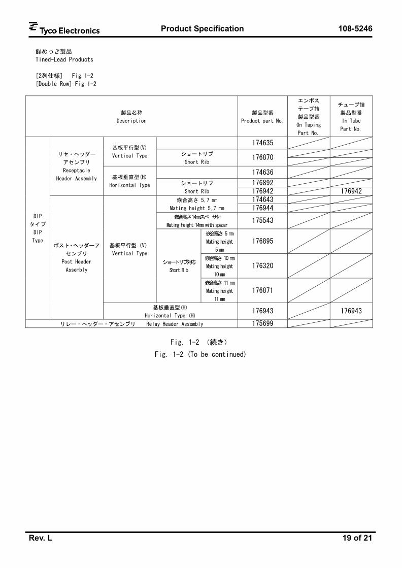
錫めっき製品
Tined-Lead Products
[2列仕様] Fig.1-2
[Double Row] Fig.1-2
製品名称
Description
製品型番
Product part No.
エンボス
テープ詰
製品型番
On Taping
Part No.
チューブ詰
製品型番
In Tube
Part No.
174635
基板平行型(V)
Vertical Type ショートリブ
Short Rib 176870
174636
176892
リセ・ヘッダー
アセンブリ
Receptacle
Header Assembly 基板垂直型(H)
Horizontal Type ショートリブ
Short Rib 176942 176942 174643 嵌合高さ 5,7 mm
Mating height 5,7 mm 176944 嵌合高さ 14mmスペーサ付
Mating height 14mm with spacer 175543
嵌合高さ 5 mm
Mating height
5 mm
176895
嵌合高さ 10 mm
Mating height
10 mm
176320
基板平行型(V)
Vertical Type
ショートリブ対応
Short Rib
嵌合高さ 11 mm
Mating height
11 mm
176871
DIP
タイプ
DIP
Type ポスト・ヘッダーア
センブリ
Post Header
Assembly
基板垂直型(H)
Horizontal Type (H) 176943 176943
リレー・ヘッダー・アセンブリ Relay Header Assembly 175699
Fig. 1-2 (続き)
Fig. 1-2 (To be continued)
Product Specification 108-5246
Rev. L 20 of 21
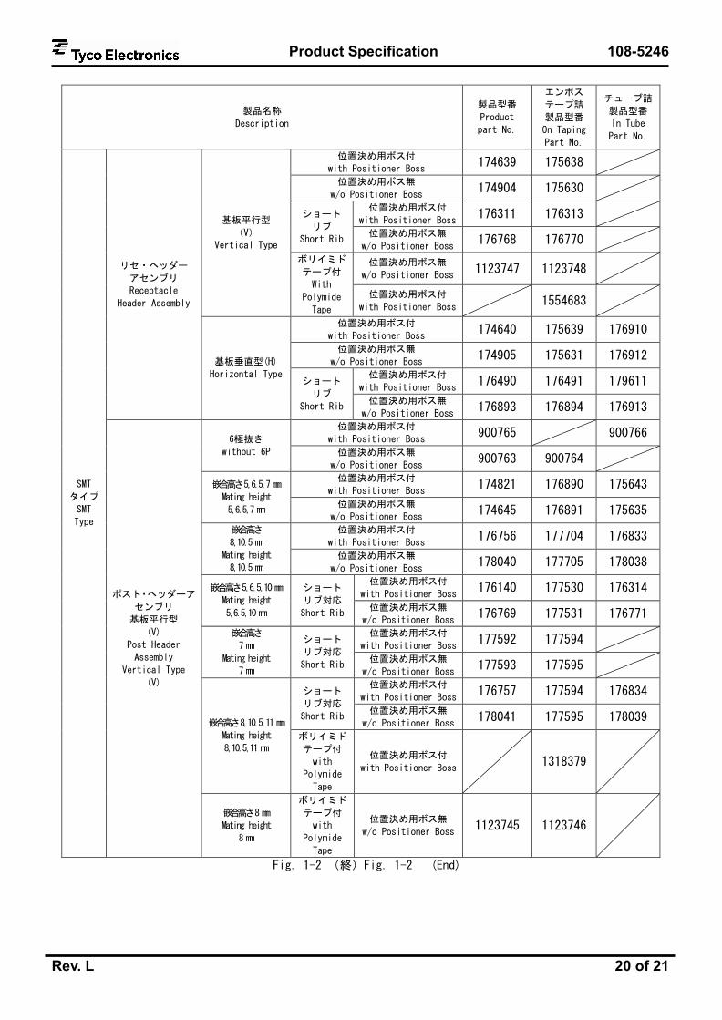
製品名称
Description
製品型番
Product
part No.
エンボス
テープ詰
製品型番
On Taping
Part No.
チューブ詰
製品型番
In Tube
Part No.
位置決め用ボス付
with Positioner Boss 174639 175638
位置決め用ボス無
w/o Positioner Boss 174904 175630
位置決め用ボス付
with Positioner Boss 176311 176313 ショート
リブ
Short Rib 位置決め用ボス無
w/o Positioner Boss 176768 176770
位置決め用ボス無
w/o Positioner Boss 1123747 1123748
基板平行型
(V)
Vertical Type
ボリイミド
テープ付
With
Polymide
Tape
位置決め用ボス付
with Positioner Boss 1554683
位置決め用ボス付
with Positioner Boss 174640 175639 176910
位置決め用ボス無
w/o Positioner Boss 174905 175631 176912
位置決め用ボス付
with Positioner Boss 176490 176491 179611
リセ・ヘッダー
アセンブリ
Receptacle
Header Assembly
基板垂直型(H)
Horizontal Type ショート
リブ
Short Rib 位置決め用ボス無
w/o Positioner Boss 176893 176894 176913
位置決め用ボス付
with Positioner Boss 900765 900766
6極抜き
without 6P 位置決め用ボス無
w/o Positioner Boss 900763 900764
位置決め用ボス付
with Positioner Boss 174821 176890 175643 嵌合高さ 5,6.5,7 mm
Mating height
5,6.5,7 mm 位置決め用ボス無
w/o Positioner Boss 174645 176891 175635
位置決め用ボス付
with Positioner Boss 176756 177704 176833
嵌合高さ
8,10.5 mm
Mating height
8,10.5 mm 位置決め用ボス無
w/o Positioner Boss 178040 177705 178038
位置決め用ボス付
with Positioner Boss 176140 177530 176314 嵌合高さ 5,6.5,10 mm
Mating height
5,6.5,10 mm
ショート
リブ対応
Short Rib 位置決め用ボス無
w/o Positioner Boss 176769 177531 176771
位置決め用ボス付
with Positioner Boss 177592 177594
嵌合高さ
7 mm
Mating height
7 mm
ショート
リブ対応
Short Rib 位置決め用ボス無
w/o Positioner Boss 177593 177595
位置決め用ボス付
with Positioner Boss 176757 177594 176834 ショート
リブ対応
Short Rib 位置決め用ボス無
w/o Positioner Boss 178041 177595 178039
嵌合高さ 8,10.5,11 mm
Mating height
8,10.5,11 mm ボリイミド
テープ付
with
Polymide
Tape
位置決め用ボス付
with Positioner Boss 1318379
SMT
タイプ
SMT
Type
ポスト・ヘッダーア
センブリ
基板平行型
(V)
Post Header
Assembly
Vertical Type
(V)
嵌合高さ 8 mm
Mating height
8 mm
ボリイミド
テープ付
with
Polymide
Tape
位置決め用ボス無
w/o Positioner Boss 1123745 1123746
Fig. 1-2 (終)Fig. 1-2 (End)

Product Specification 108-5246
Rev. L 21 of 21
金めっき製品
Gold Plated Products
[1列仕様] Fig.1-3
[Single Row] Fig.1-3
製品名称
Description
製品型番
Product
part No.
エンボステープ詰
製品型番
On Taping
Part No.
チューブ詰
製品型番
In Tube
Part No.
リセ・ヘッダー
アセンブリ
Receptacle
Header Assembly
位置決め用ボス付
with Positioner Boss 1318323 1318325
SMT
タイプ
SMT
Type
ポスト・ヘッダー
アセンブリ
基板平行型 (V)
Post Header Assembly
Vertical Type (V)
基板平行型(V)
Vertical Type
位置決め用ボス付
with Positioner Boss 1318324 1318326
[2列仕様] Fig.1-4
[Double Row] Fig.1-4
製品名称
Description
製品型番
Product
part No.
エンボステープ詰
製品型番
On Taping
Part No.
チューブ詰
製品型番
In Tube
Part No.
基板平行型
(V)
Vertical
Type
ショートリブ
位置決め用ボス付
Short Rib with Positioner Boss
178347 177851 リセ・ヘッダー
アセンブリ
Receptacle
Header Assembly
基板垂直型
(H)
Horizontal
Type
ショートリブ
位置決め用ボス付
Short Rib with Positioner Boss
353479 343580
位置決め用ボス付
with Positioner Boss 353481 353482 嵌合高さ
5 mm
Mating height
5 mm
位置決め用ボス無
w/o Positioner Boss 917090 917091
嵌合高さ
8 mm
Mating height
8 mm
位置決め用ボス付
with Positioner Boss 353508 353509
SMT
タイプ
SMT
Type ポスト・ヘッダー
アセンブリ
基板平行型(V)
Post Header Assembly
Vertical Type(V)
ショート
リブ対応
Short Rib
嵌合高さ
10 mm
Mating height
10 mm
位置決め用ボス無
w/o Positioner Boss 178386 177852