12x12 pavilion - yardcraft · this manual is designed to simplify the assembly ... 12x12 pavilion...
TRANSCRIPT

Assembly Manual
12x12Pavilion

Tools Required for Job (Not Provided)
6’ & 10’ Step
Ladders
RubberMallet
Hammer Ratchet with 9/16” & 5/8””
Socket
CordlessDrill
25’ TapeMeasure
Utility Knife
(4) 2x4x8’ Long(2) 2x4 Approx 4’ Long
for bracing header assemblies
Congratulations on purchasing your new Pavilion. Thank You for your purchase and Welcome to the YardCraft Famiy.
This manual is designed to simplify the assembly process, however we recommend having an experienced carpenter involved in the project. Please read through the entire manual before starting!
The Pavilion put together for this manual was a 12x12 Pavilion. It took 2 men, approximately 6 hours using the tools shown. However, it may take you longer since it will be a new project for you.
Take a deep breath and get at it; the satisfaction and enjoyment of this pavilion is only a few hours away. Have fun!
You have purchased a product that consists of heavy, bulky pieces. With your purchase, you assume full responsibility to have the necessary manpower and/or equipment available to unload the items. You also agree that any damage that happens to the equipment, product, or individuals during the unloading process, or during the entire construction process, is your responsibility, and neither the seller, nor the manufacturer, will be held liable for any such damage.
12x12 Pavilion Assembly Manual
Level
2” Square Drive and 1/4” Hex Drive Bit
Also a T 30 Stardrive Bit
1/4”x6” Drill Bit
C- Clamp or Vise Grip Clamp
3
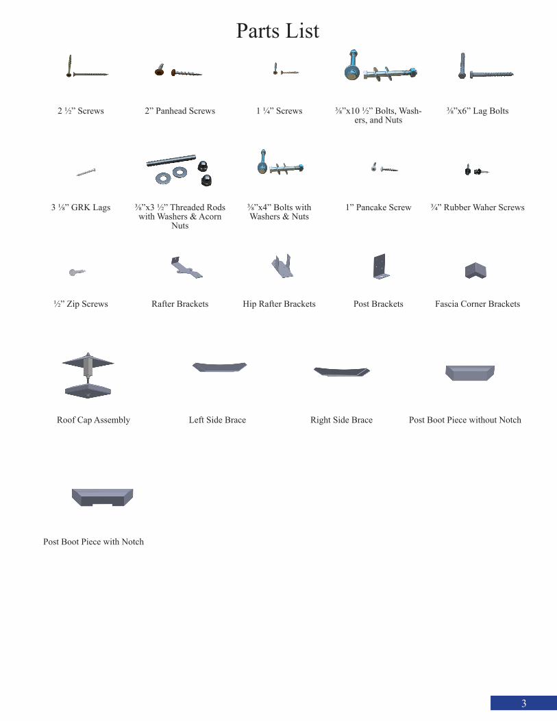
Parts List
2 1/2” Screws 1 1/4” Screws 3/8”x10 1/2” Bolts, Wash-ers, and Nuts
3/8”x6” Lag Bolts
3 1/8” GRK Lags 3/8”x3 1/2” Threaded Rods with Washers & Acorn
Nuts
3/8”x4” Bolts with Washers & Nuts
1” Pancake Screw 3/4” Rubber Waher Screws
1/2” Zip Screws Rafter Brackets Hip Rafter Brackets Post Brackets Fascia Corner Brackets
Post Boot Piece with Notch
Roof Cap Assembly Left Side Brace Post Boot Piece without Notch
2” Panhead Screws
Right Side Brace
4
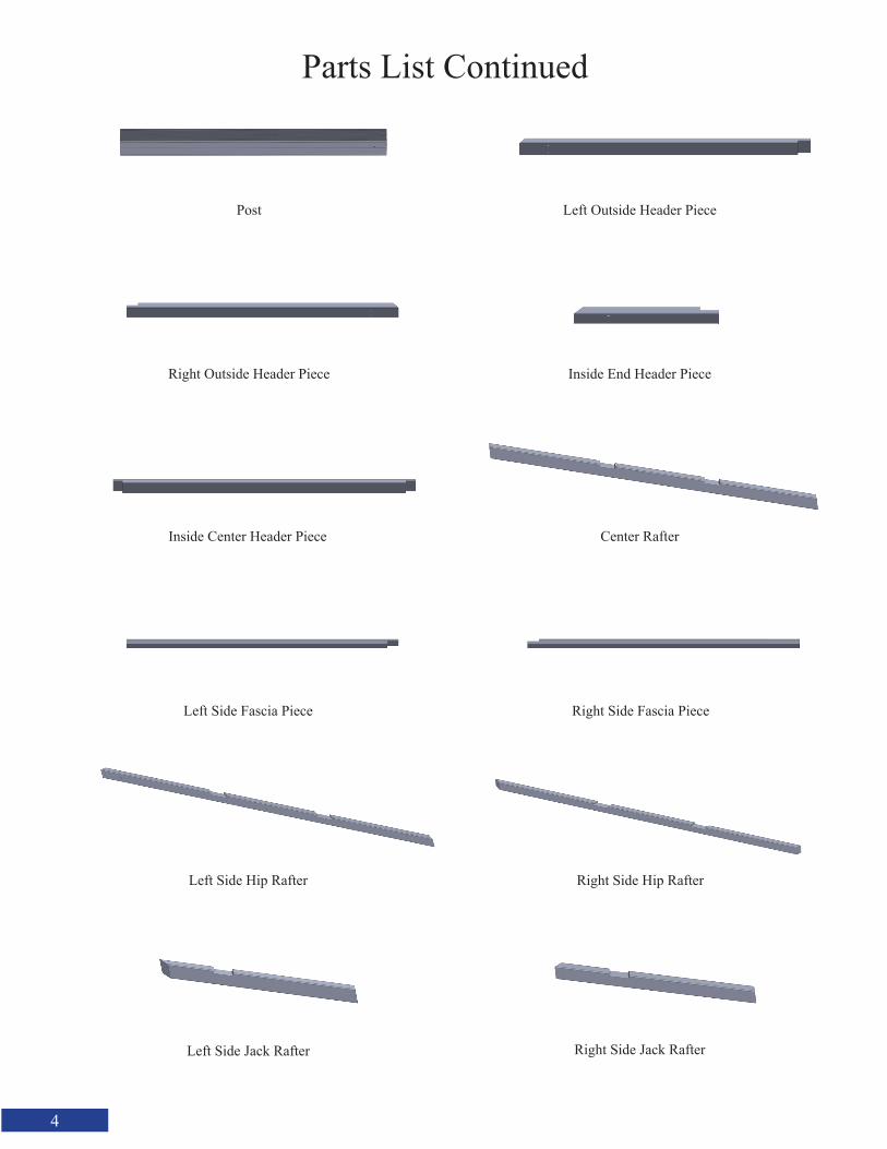
Parts List Continued
Right Outside Header Piece
Post Left Outside Header Piece
Left Side Fascia Piece
Left Side Hip Rafter
Left Side Jack Rafter
Inside End Header Piece
Inside Center Header Piece Center Rafter
Right Side Fascia Piece
Right Side Hip Rafter
Right Side Jack Rafter

5
Long Purlin Piece Short Purlin Piece
Left Side Metal Pieces Right Side Metal Pieces
Drip Edge
Ridge Cap
Ridge Clip

6
Fasten the Inside End Header Piece to each side of the Inside Center Header Piece with1 1/4” Screws through Pre-Drilled Holes.
Fasten the Left Outside Header Piece to the Right Outside Header Piece with 1 1/4” Screws.
Align the 45 Degree cut on the assembled inside Header Ply and the assembled Outside Header Ply and make flush on both sides and Fasten together with 2 1/2 Screws.
Left Outside Header Piece
Right Outside Header Piece
Inside End Header Piece
Inside Center Header Piece
Align the 2 Pieces Here.
Lay the Post down. Be careful not to damage the post. Using your own material, create some 3” or 4” blocks to lay the post on.
The white block on one end of the post indicates the bottom of the post
7
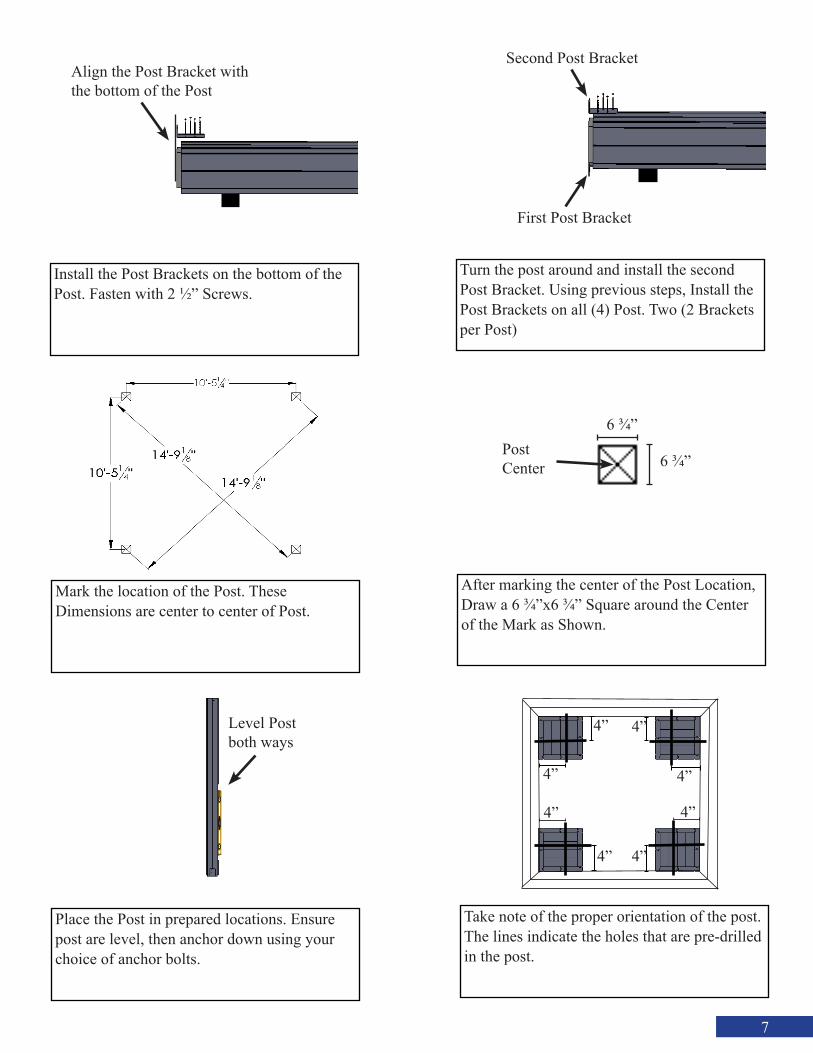
Take note of the proper orientation of the post.The lines indicate the holes that are pre-drilled in the post.
4”
4” 4”
4”
4”
4”4”
4”
Turn the post around and install the second Post Bracket. Using previous steps, Install the Post Brackets on all (4) Post. Two (2 Brackets per Post)
Mark the location of the Post. TheseDimensions are center to center of Post.
After marking the center of the Post Location, Draw a 6 3/4”x6 3/4” Square around the Center of the Mark as Shown.
Install the Post Brackets on the bottom of the Post. Fasten with 2 1/2” Screws.
Align the Post Bracket with the bottom of the Post
First Post Bracket
Second Post Bracket
6 3/4”
6 3/4”Post Center
Place the Post in prepared locations. Ensure post are level, then anchor down using your choice of anchor bolts.
Level Post both ways
8
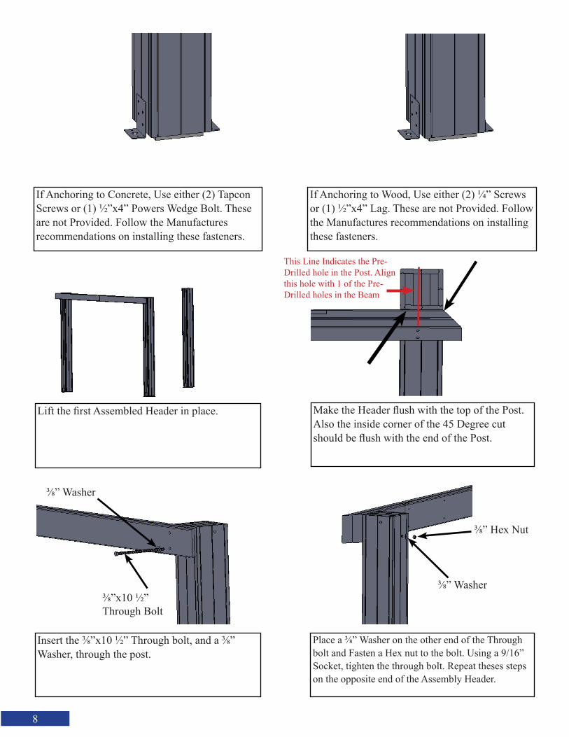
Make the Header flush with the top of the Post. Also the inside corner of the 45 Degree cut should be flush with the end of the Post.
Insert the 3/8”x10 1/2” Through bolt, and a 3/8” Washer, through the post.
Place a 3/8” Washer on the other end of the Through bolt and Fasten a Hex nut to the bolt. Using a 9/16” Socket, tighten the through bolt. Repeat theses steps on the opposite end of the Assembly Header.
Lift the first Assembled Header in place.
This Line Indicates the Pre-Drilled hole in the Post. Align this hole with 1 of the Pre-Drilled holes in the Beam
3/8” Washer
3/8”x10 1/2” Through Bolt
3/8” Washer
3/8” Hex Nut
If Anchoring to Concrete, Use either (2) Tapcon Screws or (1) 1/2”x4” Powers Wedge Bolt. These are not Provided. Follow the Manufacturesrecommendations on installing these fasteners.
If Anchoring to Wood, Use either (2) 1/4” Screws or (1) 1/2”x4” Lag. These are not Provided. Follow the Manufactures recommendations on installing these fasteners.
9
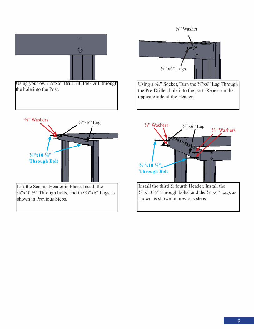
Using a 9/16” Socket, Turn the 3/8”x6” Lag Through the Pre-Drilled hole into the post. Repeat on the opposite side of the Header.
Install the third & fourth Header. Install the 3/8”x10 1/2” Through bolts, and the 3/8”x6” Lags as shown as shown in previous steps.
3/8”x10 1/2” Through Bolt
3/8”x6” Lag3/8” Washers3/8” Washers
Using your own 1/4”x6” Drill Bit, Pre-Drill through the hole into the Post.
3/8” Washer
3/8” x6” Lags
Lift the Second Header in Place. Install the3/8”x10 1/2” Through bolts, and the 3/8”x6” Lags as shown in Previous Steps.
3/8” Washers 3/8”x6” Lag
3/8”x10 1/2” Through Bolt
10
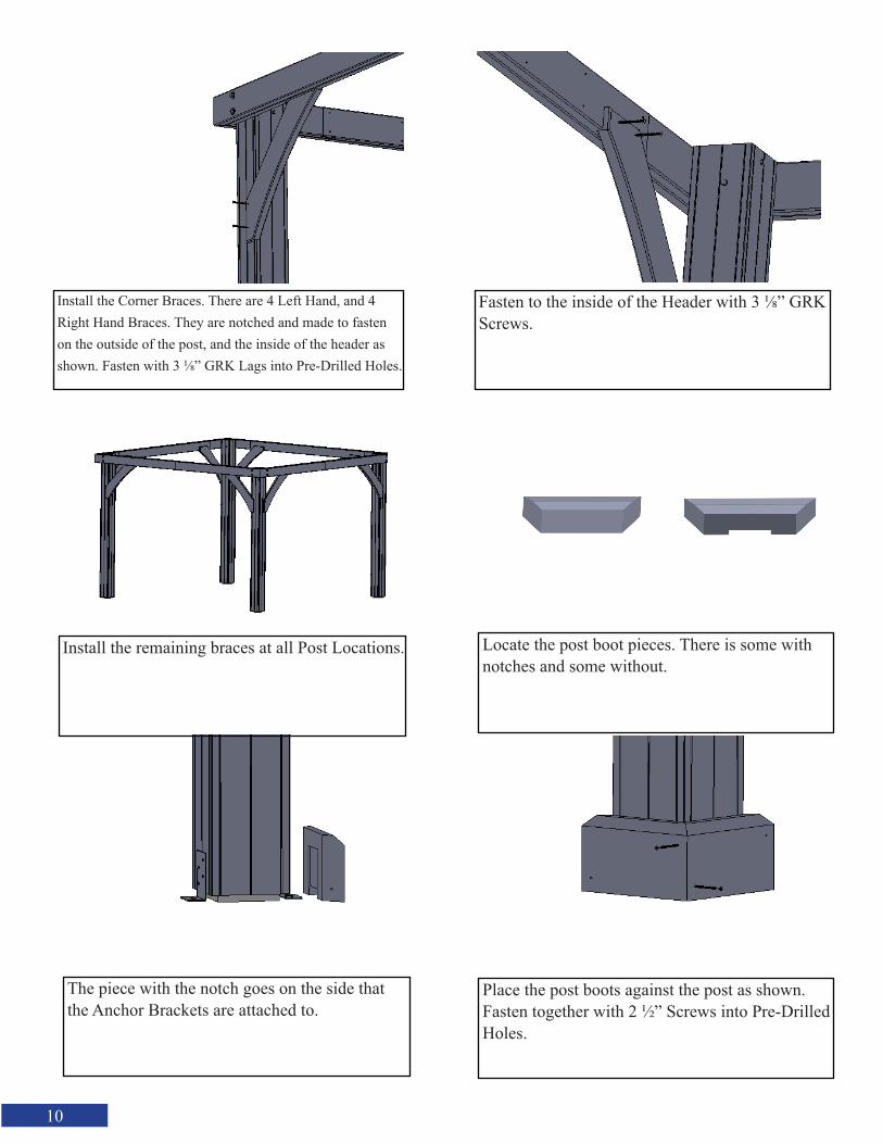
Locate the post boot pieces. There is some with notches and some without.
The piece with the notch goes on the side that the Anchor Brackets are attached to.
Place the post boots against the post as shown. Fasten together with 2 1/2” Screws into Pre-Drilled Holes.
Install the Corner Braces. There are 4 Left Hand, and 4 Right Hand Braces. They are notched and made to fasten on the outside of the post, and the inside of the header as shown. Fasten with 3 1/8” GRK Lags into Pre-Drilled Holes.
Fasten to the inside of the Header with 3 1/8” GRK Screws.
Install the remaining braces at all Post Locations.

11
Install the last 2 Post Boot Pieces as shown. Using Previous steps, Install the Post boots on all the remaining Posts, as shown in previous steps.
You are now ready to assemble the roof Panel. Start by Locating one (1) Left and one (1) Right Fascia Board.
Fasten the Left Fascia Board to the Right Fascia Board with 1 1/4” Screws through Pre-Drilled Holes. Repeat this step to assemble all Fascia Boards.
Locate the Center Rafter. Place the Center Rafter against the assembled Fascia Board.
Left Fascia Board
Right Fascia Board
12
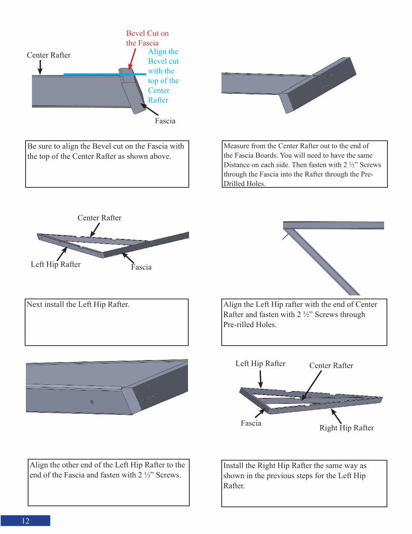
Be sure to align the Bevel cut on the Fascia with the top of the Center Rafter as shown above.
Measure from the Center Rafter out to the end of the Fascia Boards. You will need to have the same Distance on each side. Then fasten with 2 1/2” Screws through the Fascia into the Rafter through the Pre-Drilled Holes.
Next install the Left Hip Rafter. Align the Left Hip rafter with the end of Center Rafter and fasten with 2 1/2” Screws throughPre-rilled Holes.
Align the other end of the Left Hip Rafter to the end of the Fascia and fasten with 2 1/2” Screws.
Install the Right Hip Rafter the same way as shown in the previous steps for the Left HipRafter.
Center Rafter
Fascia
Bevel Cut on the Fascia
Align the Bevel cut with the top of the Center Rafter
Center Rafter
Left Hip Rafter Fascia
Left Hip Rafter Center Rafter
Right Hip RafterFascia
13
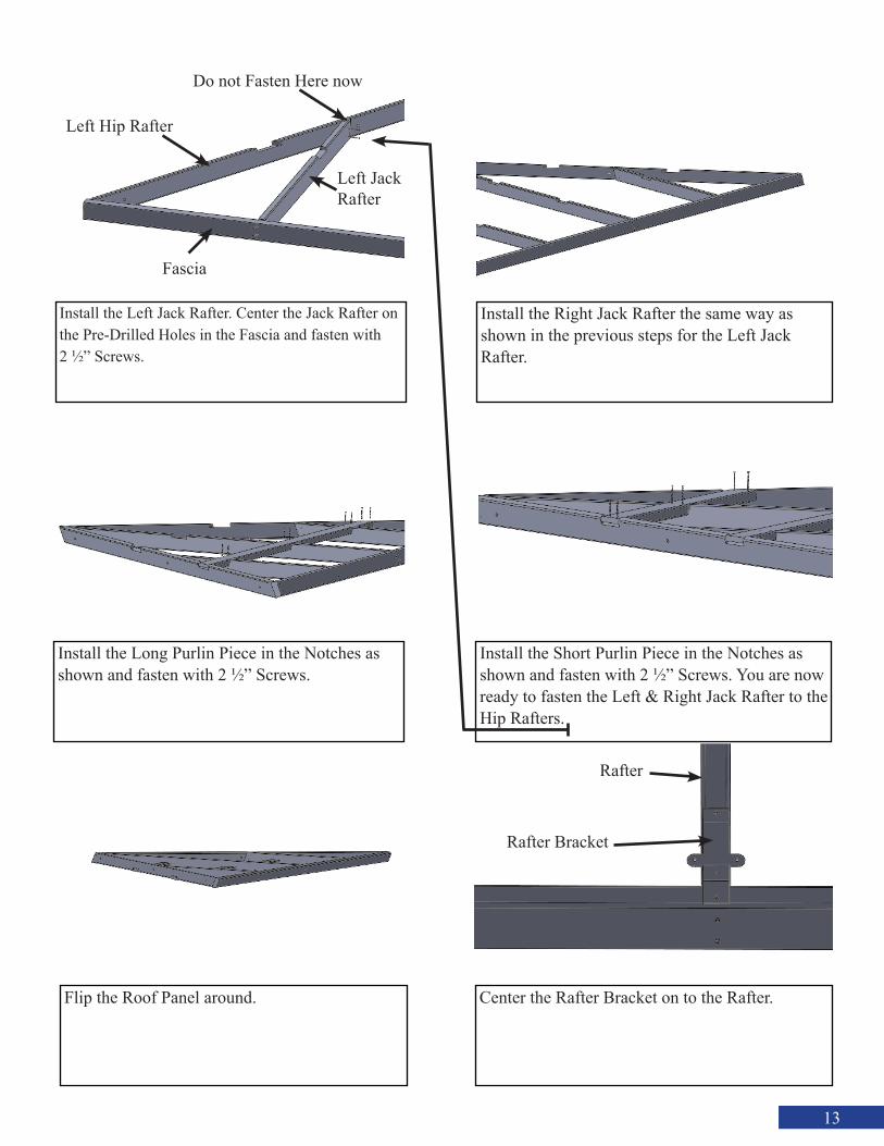
Install the Left Jack Rafter. Center the Jack Rafter on the Pre-Drilled Holes in the Fascia and fasten with2 1/2” Screws.
Install the Right Jack Rafter the same way as shown in the previous steps for the Left Jack Rafter.
Install the Long Purlin Piece in the Notches as shown and fasten with 2 1/2” Screws.
Install the Short Purlin Piece in the Notches as shown and fasten with 2 1/2” Screws. You are now ready to fasten the Left & Right Jack Rafter to the Hip Rafters.
Flip the Roof Panel around.
Left Hip Rafter
Fascia
Left Jack Rafter
Center the Rafter Bracket on to the Rafter.
Rafter Bracket
Rafter
Do not Fasten Here now
14
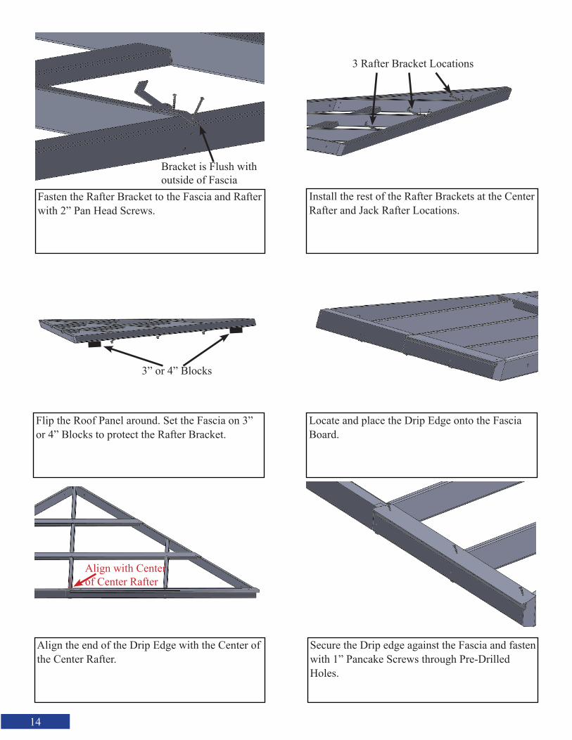
Install the rest of the Rafter Brackets at the Center Rafter and Jack Rafter Locations.
Flip the Roof Panel around. Set the Fascia on 3” or 4” Blocks to protect the Rafter Bracket.
Align the end of the Drip Edge with the Center of the Center Rafter.
Locate and place the Drip Edge onto the Fascia Board.
Secure the Drip edge against the Fascia and fasten with 1” Pancake Screws through Pre-Drilled Holes.
Fasten the Rafter Bracket to the Fascia and Rafter with 2” Pan Head Screws.
3 Rafter Bracket Locations
3” or 4” Blocks
Align with Center of Center Rafter
Bracket is Flush with outside of Fascia

15
Install the second Drip Edge. Push against the first Drip Edge as shown.
Locate and place the Ridge Clip onto the Hip Rafter.
Push Ridge Clip Against the Hip Rafter and fasten with 1” Pancake Screws through Pre-Drilled Holes.
Fasten the second Drip Edge Piece with 1”Pancake Screws through Pre-Drilled Holes.
Make the Ridge Clip flush with the end of the Center Rafter.
Repeat the previous steps to install the opposite side Ridge Clip.
Second PieceFirst Piece
Center Rafter
Make Flush
Ridge Clip

16
Assembly three (3) more Roof Panels, using the previous steps shown.
This is how your Pavilion should look with the Headers and Post Assembled.
Fasten Hip Rafter Bracket with 2” Panhead Screws into all Pre-Drilled Holes.
First Install the Hip Rafter Brackets. Place on top of the Post and Header. Align the Hip Rafter Bracket with the Headers both ways.
Install the Hip Rafter Bracket at each corner, as shown in previous steps.
After all 4 Roof Panels are assembled, You are ready to install the Roof Panels on top of the Header and Post assembly.
Align with Headers

17
Lift the first Roof Panel in Place.
Place both Hip Rafters Against the Hip Rafter Brackets.
Place the Hip Rafter of the Roof Panel into the Hip Rafter Bracket.
Fasten the Rafter Brackets to the Header with two (2) 2” Panhead Screws. One (1) on each side of the Rafter.v
Hip Rafter Hip Rafter
Hip Rafter Brackets
Rafter
ScrewScrew
Fasten your own 2x4 into the Center Rafter with 2 1/2” Screws to create a Temporary prop for the Roof Panel.
2x4 Roof Prop2 Screws into Rafter
Also fasten one (1) Screw into the side of the Header.

18
Lift the Second Roof Panel in Place.
Prepare the 3 1/2” Threaded Rods. Place a 3/8” Washer and one (1) Acorn Nut on one end of the3 1/2” Threaded Rod. Prepare all the 3 1/2” Thread-ed Rods before going to the next step.
Insert the Prepared 3 1/2” Threaded Rod into the Pre-Drilled Holes in the Hip Rafters.
Align the 2 Hip Rafters. You may need to adjust the Roof Prop so the Hip Rafters are Aligned. You may need a C-Clamp to clamp the 2 Hip Rafters together.
Place another 3/8” Washer and Acorn Nut onto the opposite end of the 3 1/2” Threaded Rod. Tighten both ends using the correct size Socket or Wrench.
Fasten the rest of the Rafter Brackets to theHeader with 2” Panhead Screws.
Rafter Bracket Locations
19
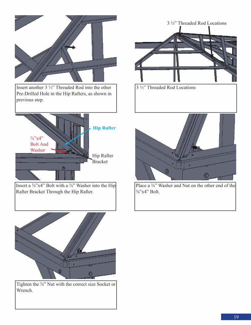
Insert another 3 1/2” Threaded Rod into the other Pre-Drilled Hole in the Hip Rafters, as shown in previous step.
Insert a 3/8”x4” Bolt with a 3/8” Washer into the Hip Rafter Bracket Through the Hip Rafter.
Tighten the 3/8” Nut with the correct size Socket or Wrench.
3 1/2” Threaded Rod Locations
Place a 3/8” Washer and Nut on the other end of the 3/8”x4” Bolt.
3 1/2” Threaded Rod Locations
Hip Rafter
Hip Rafter Bracket
3/8”x4” Bolt And Washer
20
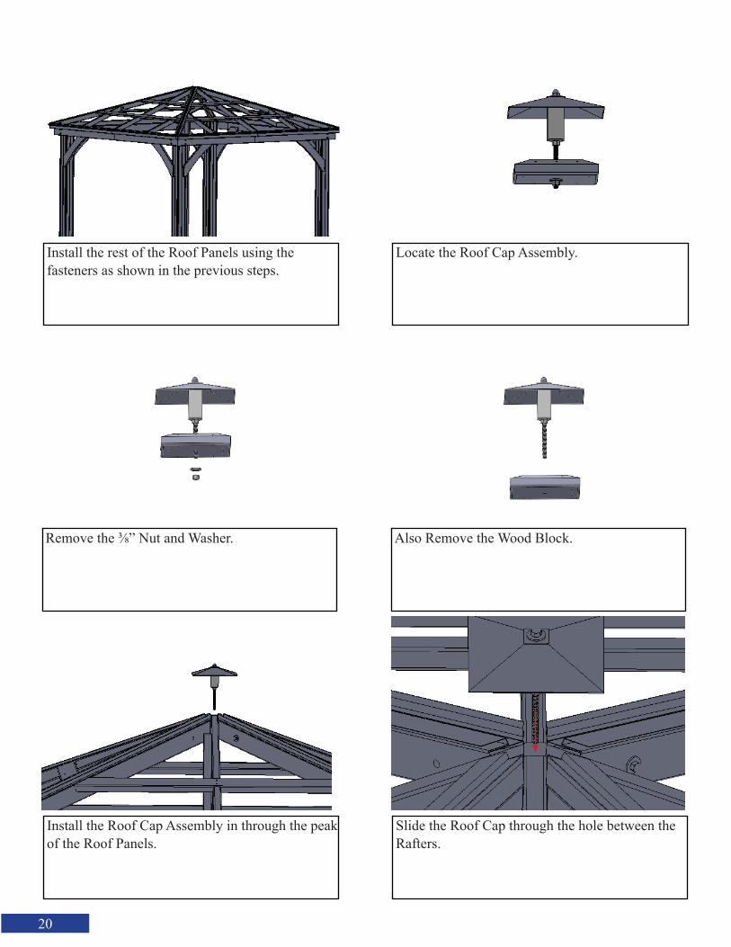
Install the rest of the Roof Panels using thefasteners as shown in the previous steps.
Remove the 3/8” Nut and Washer.
Install the Roof Cap Assembly in through the peak of the Roof Panels.
Locate the Roof Cap Assembly.
Also Remove the Wood Block.
Slide the Roof Cap through the hole between the Rafters.

21
This is what your Roof Cap should look like at this point.
Push the Fascia Corner Brackets against theFascia both ways. Slide it in between the Fascia and the Drip edge, and up against the bottom of the Fascia. Fasten with 2” Panhead Screws at four (4) Locations as shown.
Remove the Temporary Roof Prop.
Install the Fascia Corner Brackets.
Install the Fascia Corner Brackets on each Corner, as shown in previous steps.
Locate the Longest of the Left Side Metal Pieces. Lift onto the Roof Panel.
Roof Cap
Roof Prop

22
Align the metal with the splice in the Drip Edge as shown here.
Keeping the Metal Aligned with the Drip Edge, put 2 more 3/4” Rubber Washer Screws into the Pre-Drilled Holes. The top of the Metal Panel will be in the Ridge Clip channel.
Overlap the second piece onto the first piece.
Align the Metal With the Drip Edge. Fasten into Pre-Drilled Holes with 3/4” Rubber Washer Screws.
Locate the longest of the Right Side Metal Pieces.
Slide up into place.
Align this point of the Metal with the splice in Drip Edge
3/4” Rubber Washer Screws
ScrewLocations
First Piece Second Piece
23
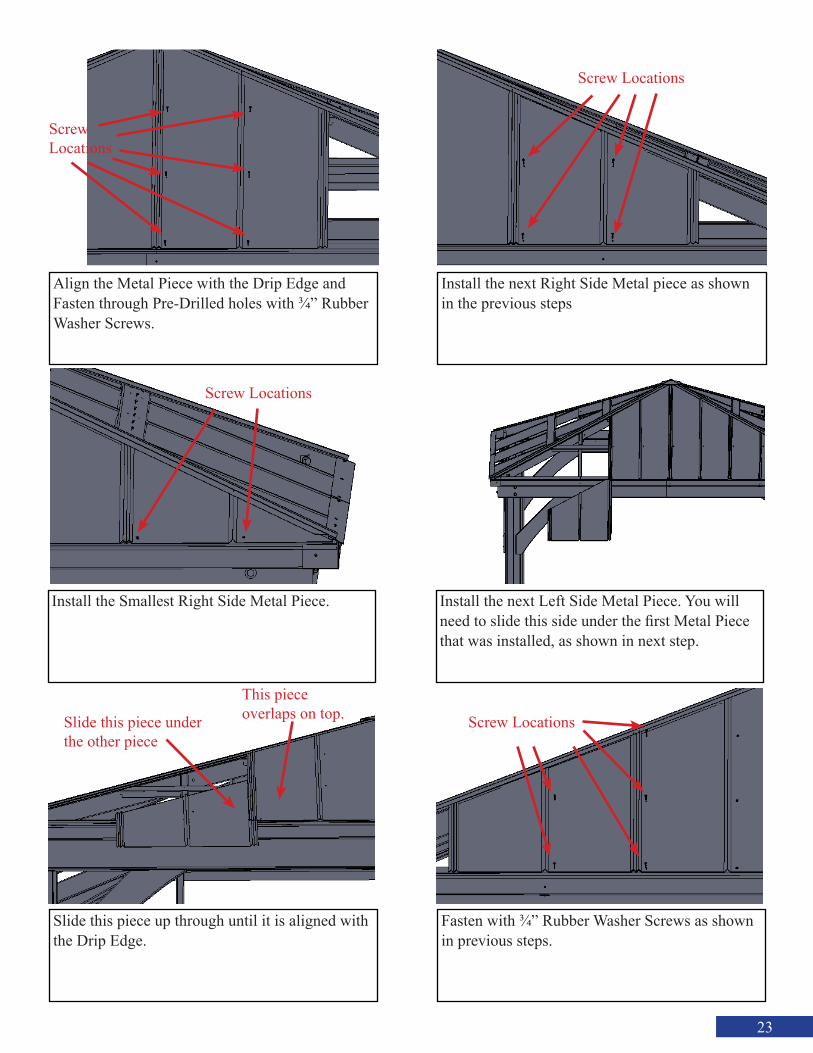
Align the Metal Piece with the Drip Edge and Fasten through Pre-Drilled holes with 3/4” Rubber Washer Screws.
Install the Smallest Right Side Metal Piece.
Slide this piece up through until it is aligned with the Drip Edge.
Install the next Right Side Metal piece as shown in the previous steps
Install the next Left Side Metal Piece. You will need to slide this side under the first Metal Piece that was installed, as shown in next step.
Fasten with 3/4” Rubber Washer Screws as shown in previous steps.
Screw Locations
Screw Locations
Screw Locations
Slide this piece under the other piece
This piece overlaps on top. Screw Locations
24
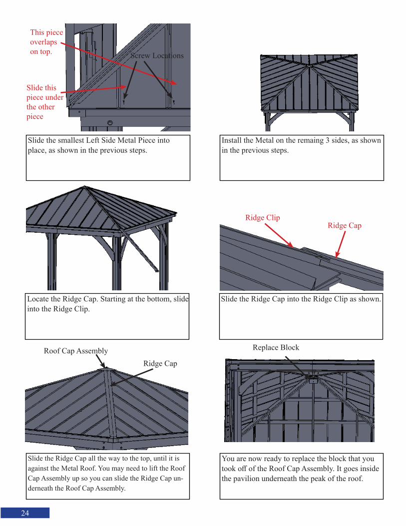
Slide the smallest Left Side Metal Piece into place, as shown in the previous steps.
Locate the Ridge Cap. Starting at the bottom, slide into the Ridge Clip.
Slide the Ridge Cap all the way to the top, until it is against the Metal Roof. You may need to lift the Roof Cap Assembly up so you can slide the Ridge Cap un-derneath the Roof Cap Assembly.
Install the Metal on the remaing 3 sides, as shown in the previous steps.
Slide the Ridge Cap into the Ridge Clip as shown.
You are now ready to replace the block that you took off of the Roof Cap Assembly. It goes inside the pavilion underneath the peak of the roof.
Slide this piece under the other piece
This piece overlaps on top. Screw Locations
Ridge ClipRidge Cap
Roof Cap AssemblyRidge Cap
Replace Block
25
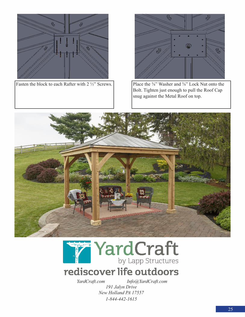
Fasten the block to each Rafter with 2 1/2” Screws. Place the 3/8” Washer and 3/8” Lock Nut onto the Bolt. Tighten just enough to pull the Roof Cap snug against the Metal Roof on top.
YardCraft.com [email protected] Jalyn Drive
New Holland PA 175571-844-442-1615