13383 en - super-precision bearings_tcm_12-129877
TRANSCRIPT

Super-precision bearings

® SKF, BeyondZero, KMT and KMTA are registered trademarks of the SKF Group.
™ NitroMax is a trademark of the SKF Group.
Apple is a trademark of Apple Inc., registered in the US and other countries.
Google Play is a trademark of Google Inc.
© SKF Group 2013The contents of this publication are the copyright of the publisher and may not be reproduced (even extracts) unless prior written permission is granted. Every care has been taken to ensure the accuracy of the information contained in this publication but no liability can be accepted for any loss or damage whether direct, indirect or consequential arising out of the use of the information contained herein.
PUB BU/P1 13383 EN · July 2013
This publication supersedes publication 6002.
Certain image(s) used under license from Shutterstock.com
SKF mobile appsSKF mobile apps are available from both Apple App Store and Google Play. These apps provide useful information and allow you to make critical calculations, providing SKF Knowledge Engineering at your fingertips.
Apple AppStore
Google Play
FSC placeholder
3
1
2
4
5
6
7
8
9
Principles of bearing selection and application
Angular contact ball bearings
Cylindrical roller bearings
Double direction angular contact thrust ball bearings
Axial-radial cylindrical roller bearings
Angular contact thrust ball bearings for screw drives
Precision lock nuts
Gauges
Indexes
1

This is SKF . . . . . . . . . . . . . . . . . . . . . . . . . . . . . . . . . . . . . . . . . . . . . . . . . . . . . . . . . . . . . . . . . 6SKF – the knowledge engineering company . . . . . . . . . . . . . . . . . . . . . . . . . . . . . . . . . . . . . . 8Unit conversions . . . . . . . . . . . . . . . . . . . . . . . . . . . . . . . . . . . . . . . . . . . . . . . . . . . . . . . . . . . . 10Foreword . . . . . . . . . . . . . . . . . . . . . . . . . . . . . . . . . . . . . . . . . . . . . . . . . . . . . . . . . . . . . . . . . . 11
1 Principles of bearing selection and application . . . . . . . . . . . . . . . . . . . . . . . . . . . . . . . . . 19Selecting super-precision bearings . . . . . . . . . . . . . . . . . . . . . . . . . . . . . . . . . . . . . . . . . . . . 20
Bearing types and designs . . . . . . . . . . . . . . . . . . . . . . . . . . . . . . . . . . . . . . . . . . . . . . . . . 21Basic selection criteria . . . . . . . . . . . . . . . . . . . . . . . . . . . . . . . . . . . . . . . . . . . . . . . . . . . . 23
Bearing life and load ratings . . . . . . . . . . . . . . . . . . . . . . . . . . . . . . . . . . . . . . . . . . . . . . . . . . 33Dynamic bearing loads and life . . . . . . . . . . . . . . . . . . . . . . . . . . . . . . . . . . . . . . . . . . . . . . 33Permissible static loads . . . . . . . . . . . . . . . . . . . . . . . . . . . . . . . . . . . . . . . . . . . . . . . . . . . 36
Friction . . . . . . . . . . . . . . . . . . . . . . . . . . . . . . . . . . . . . . . . . . . . . . . . . . . . . . . . . . . . . . . . . . 37Effects of clearance and preload on friction . . . . . . . . . . . . . . . . . . . . . . . . . . . . . . . . . . . . 37Effects of grease fill on friction . . . . . . . . . . . . . . . . . . . . . . . . . . . . . . . . . . . . . . . . . . . . . . 37Frictional behaviour of hybrid bearings . . . . . . . . . . . . . . . . . . . . . . . . . . . . . . . . . . . . . . . 37
Speeds . . . . . . . . . . . . . . . . . . . . . . . . . . . . . . . . . . . . . . . . . . . . . . . . . . . . . . . . . . . . . . . . . . . 38Permissible speeds . . . . . . . . . . . . . . . . . . . . . . . . . . . . . . . . . . . . . . . . . . . . . . . . . . . . . . . 39Attainable speeds . . . . . . . . . . . . . . . . . . . . . . . . . . . . . . . . . . . . . . . . . . . . . . . . . . . . . . . . 44Attainable speeds for typical spindle bearing systems . . . . . . . . . . . . . . . . . . . . . . . . . . . . 44
Bearing specifics . . . . . . . . . . . . . . . . . . . . . . . . . . . . . . . . . . . . . . . . . . . . . . . . . . . . . . . . . . . 46Boundary dimensions . . . . . . . . . . . . . . . . . . . . . . . . . . . . . . . . . . . . . . . . . . . . . . . . . . . . . 46Tolerances . . . . . . . . . . . . . . . . . . . . . . . . . . . . . . . . . . . . . . . . . . . . . . . . . . . . . . . . . . . . . . 47Preload and internal clearance . . . . . . . . . . . . . . . . . . . . . . . . . . . . . . . . . . . . . . . . . . . . . . 50Materials . . . . . . . . . . . . . . . . . . . . . . . . . . . . . . . . . . . . . . . . . . . . . . . . . . . . . . . . . . . . . . . 51
Design considerations . . . . . . . . . . . . . . . . . . . . . . . . . . . . . . . . . . . . . . . . . . . . . . . . . . . . . . . 57Bearing arrangements . . . . . . . . . . . . . . . . . . . . . . . . . . . . . . . . . . . . . . . . . . . . . . . . . . . . 57System rigidity . . . . . . . . . . . . . . . . . . . . . . . . . . . . . . . . . . . . . . . . . . . . . . . . . . . . . . . . . . 66Radial location of bearings . . . . . . . . . . . . . . . . . . . . . . . . . . . . . . . . . . . . . . . . . . . . . . . . . 70Axial location of bearings . . . . . . . . . . . . . . . . . . . . . . . . . . . . . . . . . . . . . . . . . . . . . . . . . . 78Provisions for mounting and dismounting . . . . . . . . . . . . . . . . . . . . . . . . . . . . . . . . . . . . . 88Bearing preload . . . . . . . . . . . . . . . . . . . . . . . . . . . . . . . . . . . . . . . . . . . . . . . . . . . . . . . . . 90Sealing solutions . . . . . . . . . . . . . . . . . . . . . . . . . . . . . . . . . . . . . . . . . . . . . . . . . . . . . . . . . 95
Lubrication . . . . . . . . . . . . . . . . . . . . . . . . . . . . . . . . . . . . . . . . . . . . . . . . . . . . . . . . . . . . . . . 99Grease lubrication . . . . . . . . . . . . . . . . . . . . . . . . . . . . . . . . . . . . . . . . . . . . . . . . . . . . . . . . 99Oil lubrication . . . . . . . . . . . . . . . . . . . . . . . . . . . . . . . . . . . . . . . . . . . . . . . . . . . . . . . . . . . 113Lubricant storage . . . . . . . . . . . . . . . . . . . . . . . . . . . . . . . . . . . . . . . . . . . . . . . . . . . . . . . . 122
Content
2

Mounting and dismounting . . . . . . . . . . . . . . . . . . . . . . . . . . . . . . . . . . . . . . . . . . . . . . . . . . . 123Where to mount . . . . . . . . . . . . . . . . . . . . . . . . . . . . . . . . . . . . . . . . . . . . . . . . . . . . . . . . . 123Methods and tools . . . . . . . . . . . . . . . . . . . . . . . . . . . . . . . . . . . . . . . . . . . . . . . . . . . . . . . . 123Mounting recommendations . . . . . . . . . . . . . . . . . . . . . . . . . . . . . . . . . . . . . . . . . . . . . . . . 123Test running . . . . . . . . . . . . . . . . . . . . . . . . . . . . . . . . . . . . . . . . . . . . . . . . . . . . . . . . . . . . 124Dismounting . . . . . . . . . . . . . . . . . . . . . . . . . . . . . . . . . . . . . . . . . . . . . . . . . . . . . . . . . . . . 124Reusing bearings. . . . . . . . . . . . . . . . . . . . . . . . . . . . . . . . . . . . . . . . . . . . . . . . . . . . . . . . . 124SKF spindle service . . . . . . . . . . . . . . . . . . . . . . . . . . . . . . . . . . . . . . . . . . . . . . . . . . . . . . . 125
Bearing storage . . . . . . . . . . . . . . . . . . . . . . . . . . . . . . . . . . . . . . . . . . . . . . . . . . . . . . . . . . . . 125
2 Angular contact ball bearings . . . . . . . . . . . . . . . . . . . . . . . . . . . . . . . . . . . . . . . . . . . . . . . 127Assortment . . . . . . . . . . . . . . . . . . . . . . . . . . . . . . . . . . . . . . . . . . . . . . . . . . . . . . . . . . . . . . . 128Designs and variants . . . . . . . . . . . . . . . . . . . . . . . . . . . . . . . . . . . . . . . . . . . . . . . . . . . . . . . . 128Bearing arrangement design . . . . . . . . . . . . . . . . . . . . . . . . . . . . . . . . . . . . . . . . . . . . . . . . . 141Markings on bearings and bearing sets . . . . . . . . . . . . . . . . . . . . . . . . . . . . . . . . . . . . . . . . . 145Bearing data . . . . . . . . . . . . . . . . . . . . . . . . . . . . . . . . . . . . . . . . . . . . . . . . . . . . . . . . . . . . . . 146Preload . . . . . . . . . . . . . . . . . . . . . . . . . . . . . . . . . . . . . . . . . . . . . . . . . . . . . . . . . . . . . . . . . . 151Axial stiffness . . . . . . . . . . . . . . . . . . . . . . . . . . . . . . . . . . . . . . . . . . . . . . . . . . . . . . . . . . . . . 173Fitting and clamping bearing rings . . . . . . . . . . . . . . . . . . . . . . . . . . . . . . . . . . . . . . . . . . . . . 183Load carrying capacity of bearing sets . . . . . . . . . . . . . . . . . . . . . . . . . . . . . . . . . . . . . . . . . . 189Equivalent bearing loads . . . . . . . . . . . . . . . . . . . . . . . . . . . . . . . . . . . . . . . . . . . . . . . . . . . . . 190Attainable speeds . . . . . . . . . . . . . . . . . . . . . . . . . . . . . . . . . . . . . . . . . . . . . . . . . . . . . . . . . . 192Mounting . . . . . . . . . . . . . . . . . . . . . . . . . . . . . . . . . . . . . . . . . . . . . . . . . . . . . . . . . . . . . . . . . 194Designation system . . . . . . . . . . . . . . . . . . . . . . . . . . . . . . . . . . . . . . . . . . . . . . . . . . . . . . . . . 196Product table2.1 Angular contact ball bearings . . . . . . . . . . . . . . . . . . . . . . . . . . . . . . . . . . . . . . . . . . . . . 198
3 Cylindrical roller bearings. . . . . . . . . . . . . . . . . . . . . . . . . . . . . . . . . . . . . . . . . . . . . . . . . . . 263Designs and variants . . . . . . . . . . . . . . . . . . . . . . . . . . . . . . . . . . . . . . . . . . . . . . . . . . . . . . . 264Bearing data . . . . . . . . . . . . . . . . . . . . . . . . . . . . . . . . . . . . . . . . . . . . . . . . . . . . . . . . . . . . . . 269Radial internal clearance or preload in mounted bearings . . . . . . . . . . . . . . . . . . . . . . . . . . . 275Radial stiffness . . . . . . . . . . . . . . . . . . . . . . . . . . . . . . . . . . . . . . . . . . . . . . . . . . . . . . . . . . . . 275Equivalent bearing loads . . . . . . . . . . . . . . . . . . . . . . . . . . . . . . . . . . . . . . . . . . . . . . . . . . . . 277Attainable speeds . . . . . . . . . . . . . . . . . . . . . . . . . . . . . . . . . . . . . . . . . . . . . . . . . . . . . . . . . . 277Design considerations . . . . . . . . . . . . . . . . . . . . . . . . . . . . . . . . . . . . . . . . . . . . . . . . . . . . . . . 278Mounting . . . . . . . . . . . . . . . . . . . . . . . . . . . . . . . . . . . . . . . . . . . . . . . . . . . . . . . . . . . . . . . . . 280Designation system . . . . . . . . . . . . . . . . . . . . . . . . . . . . . . . . . . . . . . . . . . . . . . . . . . . . . . . . . 286Product tables3.1 Single row cylindrical roller bearings . . . . . . . . . . . . . . . . . . . . . . . . . . . . . . . . . . . . . . . 2883.2 Double row cylindrical roller bearings . . . . . . . . . . . . . . . . . . . . . . . . . . . . . . . . . . . . . . . 294
4 Double direction angular contact thrust ball bearings . . . . . . . . . . . . . . . . . . . . . . . . . . . 301Designs and variants . . . . . . . . . . . . . . . . . . . . . . . . . . . . . . . . . . . . . . . . . . . . . . . . . . . . . . . 302Markings on bearings . . . . . . . . . . . . . . . . . . . . . . . . . . . . . . . . . . . . . . . . . . . . . . . . . . . . . . . 305Bearing data . . . . . . . . . . . . . . . . . . . . . . . . . . . . . . . . . . . . . . . . . . . . . . . . . . . . . . . . . . . . . . 306Preload . . . . . . . . . . . . . . . . . . . . . . . . . . . . . . . . . . . . . . . . . . . . . . . . . . . . . . . . . . . . . . . . . . 308Axial stiffness . . . . . . . . . . . . . . . . . . . . . . . . . . . . . . . . . . . . . . . . . . . . . . . . . . . . . . . . . . . . . 309Equivalent bearing loads . . . . . . . . . . . . . . . . . . . . . . . . . . . . . . . . . . . . . . . . . . . . . . . . . . . . 310Attainable speeds . . . . . . . . . . . . . . . . . . . . . . . . . . . . . . . . . . . . . . . . . . . . . . . . . . . . . . . . . . 310Mounting . . . . . . . . . . . . . . . . . . . . . . . . . . . . . . . . . . . . . . . . . . . . . . . . . . . . . . . . . . . . . . . . . 310Designation system . . . . . . . . . . . . . . . . . . . . . . . . . . . . . . . . . . . . . . . . . . . . . . . . . . . . . . . . . 311Product table4.1 Double direction angular contact thrust ball bearings . . . . . . . . . . . . . . . . . . . . . . . . . . 312
3
Content
5 Axial-radial cylindrical roller bearings . . . . . . . . . . . . . . . . . . . . . . . . . . . . . . . . . . . . . . . . 319Designs and variants . . . . . . . . . . . . . . . . . . . . . . . . . . . . . . . . . . . . . . . . . . . . . . . . . . . . . . . 320Bearing data . . . . . . . . . . . . . . . . . . . . . . . . . . . . . . . . . . . . . . . . . . . . . . . . . . . . . . . . . . . . . . 321Preload and stiffness . . . . . . . . . . . . . . . . . . . . . . . . . . . . . . . . . . . . . . . . . . . . . . . . . . . . . . . 322Friction . . . . . . . . . . . . . . . . . . . . . . . . . . . . . . . . . . . . . . . . . . . . . . . . . . . . . . . . . . . . . . . . . . 322Lubrication . . . . . . . . . . . . . . . . . . . . . . . . . . . . . . . . . . . . . . . . . . . . . . . . . . . . . . . . . . . . . . . 324Design considerations . . . . . . . . . . . . . . . . . . . . . . . . . . . . . . . . . . . . . . . . . . . . . . . . . . . . . . . 324Load carrying capacity . . . . . . . . . . . . . . . . . . . . . . . . . . . . . . . . . . . . . . . . . . . . . . . . . . . . . . 327Equivalent bearing loads . . . . . . . . . . . . . . . . . . . . . . . . . . . . . . . . . . . . . . . . . . . . . . . . . . . . 327Permissible moment load . . . . . . . . . . . . . . . . . . . . . . . . . . . . . . . . . . . . . . . . . . . . . . . . . . . . 328Mounting . . . . . . . . . . . . . . . . . . . . . . . . . . . . . . . . . . . . . . . . . . . . . . . . . . . . . . . . . . . . . . . . . 330Designation system . . . . . . . . . . . . . . . . . . . . . . . . . . . . . . . . . . . . . . . . . . . . . . . . . . . . . . . . . 333Product tables5.1 Axial-radial cylindrical roller bearings . . . . . . . . . . . . . . . . . . . . . . . . . . . . . . . . . . . . . . 334
6 Angular contact thrust ball bearings for screw drives . . . . . . . . . . . . . . . . . . . . . . . . . . . 337Designs and variants . . . . . . . . . . . . . . . . . . . . . . . . . . . . . . . . . . . . . . . . . . . . . . . . . . . . . . . . 338Bearing arrangement design . . . . . . . . . . . . . . . . . . . . . . . . . . . . . . . . . . . . . . . . . . . . . . . . . 346Markings on bearings . . . . . . . . . . . . . . . . . . . . . . . . . . . . . . . . . . . . . . . . . . . . . . . . . . . . . . . 352Bearing data . . . . . . . . . . . . . . . . . . . . . . . . . . . . . . . . . . . . . . . . . . . . . . . . . . . . . . . . . . . . . . 353Preload . . . . . . . . . . . . . . . . . . . . . . . . . . . . . . . . . . . . . . . . . . . . . . . . . . . . . . . . . . . . . . . . . . 355Axial stiffness . . . . . . . . . . . . . . . . . . . . . . . . . . . . . . . . . . . . . . . . . . . . . . . . . . . . . . . . . . . . . 358Frictional moment . . . . . . . . . . . . . . . . . . . . . . . . . . . . . . . . . . . . . . . . . . . . . . . . . . . . . . . . . . 360Lifting force . . . . . . . . . . . . . . . . . . . . . . . . . . . . . . . . . . . . . . . . . . . . . . . . . . . . . . . . . . . . . . . 360Load carrying capacity of bearing sets . . . . . . . . . . . . . . . . . . . . . . . . . . . . . . . . . . . . . . . . . . 361Equivalent bearing loads . . . . . . . . . . . . . . . . . . . . . . . . . . . . . . . . . . . . . . . . . . . . . . . . . . . . . 361Axial load carrying capacity . . . . . . . . . . . . . . . . . . . . . . . . . . . . . . . . . . . . . . . . . . . . . . . . . . 362Mounting . . . . . . . . . . . . . . . . . . . . . . . . . . . . . . . . . . . . . . . . . . . . . . . . . . . . . . . . . . . . . . . . . 362Attainable speeds . . . . . . . . . . . . . . . . . . . . . . . . . . . . . . . . . . . . . . . . . . . . . . . . . . . . . . . . . . 363Designation system . . . . . . . . . . . . . . . . . . . . . . . . . . . . . . . . . . . . . . . . . . . . . . . . . . . . . . . . . 364Product tables6.1 Single direction angular contact thrust ball bearings . . . . . . . . . . . . . . . . . . . . . . . . . . . 3666.2 Double direction angular contact thrust ball bearings . . . . . . . . . . . . . . . . . . . . . . . . . . 3686.3 Double direction angular contact thrust ball bearings for bolt mounting . . . . . . . . . . . . 3706.4 Cartridge units with a flanged housing . . . . . . . . . . . . . . . . . . . . . . . . . . . . . . . . . . . . . . 372
7 Precision lock nuts . . . . . . . . . . . . . . . . . . . . . . . . . . . . . . . . . . . . . . . . . . . . . . . . . . . . . . . . 375Designs . . . . . . . . . . . . . . . . . . . . . . . . . . . . . . . . . . . . . . . . . . . . . . . . . . . . . . . . . . . . . . . . . . 376Product data . . . . . . . . . . . . . . . . . . . . . . . . . . . . . . . . . . . . . . . . . . . . . . . . . . . . . . . . . . . . . . 378Installation and removal . . . . . . . . . . . . . . . . . . . . . . . . . . . . . . . . . . . . . . . . . . . . . . . . . . . . . 379Designation system . . . . . . . . . . . . . . . . . . . . . . . . . . . . . . . . . . . . . . . . . . . . . . . . . . . . . . . . . 382Product tables7.1 KMT precision lock nuts with locking pins . . . . . . . . . . . . . . . . . . . . . . . . . . . . . . . . . . . . 3847.2 KMTA precision lock nuts with locking pins . . . . . . . . . . . . . . . . . . . . . . . . . . . . . . . . . . . 3867.3 KMD precision lock nuts with axial locking screws . . . . . . . . . . . . . . . . . . . . . . . . . . . . . 388
4

8 Gauges . . . . . . . . . . . . . . . . . . . . . . . . . . . . . . . . . . . . . . . . . . . . . . . . . . . . . . . . . . . . . . . . . . 391GRA 30 ring gauges . . . . . . . . . . . . . . . . . . . . . . . . . . . . . . . . . . . . . . . . . . . . . . . . . . . . . . . . 393Product table8.1 GRA 30 ring gauges . . . . . . . . . . . . . . . . . . . . . . . . . . . . . . . . . . . . . . . . . . . . . . . . . . . . . 394DMB taper gauges . . . . . . . . . . . . . . . . . . . . . . . . . . . . . . . . . . . . . . . . . . . . . . . . . . . . . . . . . 396Product table8.2 DMB taper gauges . . . . . . . . . . . . . . . . . . . . . . . . . . . . . . . . . . . . . . . . . . . . . . . . . . . . . . 398GB 30 and GB 10 internal clearance gauges . . . . . . . . . . . . . . . . . . . . . . . . . . . . . . . . . . . . . 400Product tables8.3 GB 30 and GB 10 internal clearance gauges for cylindrical roller bearings . . . . . . . . . . 402GB 49 internal clearance gauges . . . . . . . . . . . . . . . . . . . . . . . . . . . . . . . . . . . . . . . . . . . . . . 404Product tables8.4 GB 49 internal clearance gauges for cylindrical roller bearings . . . . . . . . . . . . . . . . . . . 406
9 Indexes . . . . . . . . . . . . . . . . . . . . . . . . . . . . . . . . . . . . . . . . . . . . . . . . . . . . . . . . . . . . . . . . . . 408Text index . . . . . . . . . . . . . . . . . . . . . . . . . . . . . . . . . . . . . . . . . . . . . . . . . . . . . . . . . . . . . . . . . . 409Product index . . . . . . . . . . . . . . . . . . . . . . . . . . . . . . . . . . . . . . . . . . . . . . . . . . . . . . . . . . . . . . . 420
5

This is SKF
From one simple but inspired solution to a mis-alignment problem in a textile mill in Sweden, and fifteen employees in 1907, SKF has grown to become a global industrial knowledge leader. Over the years we have built on our expertise in bearings, extending it to seals, mechatronics, services and lubrication systems. Our know-ledge network includes 46 000 employees, 15 000 distributor partners, offices in more than 130 countries, and a growing number of SKF Solution Factory sites around the world.
Research and development We have hands-on experience in over forty industries, based on our employees’ knowledge of real life conditions. In addition our world-leading experts and university partners who pioneer advanced theoretical research and development in areas including tribology, condi-tion monitoring, asset management and bearing life theory. Our ongoing commitment to research and devel opment helps us keep our customers at the forefront of their industries.
SKF Solution Factory makes SKF knowledge and manu facturing expertise available locally, to provide unique solutions and services to our customers.
6

Meeting the toughest challenges Our network of knowledge and experience along with our understanding of how our core technologies can be combined helps us create innovative solutions that meet the toughest of challenges. We work closely with our customers throughout the asset life cycle, helping them to profitably and re spon sibly grow their businesses.
Working for a sustainable future Since 2005, SKF has worked to reduce the negative environmental impact from our own operations and those of our suppliers. Our con-tinuing technology development intro duced the SKF BeyondZero portfolio of products and services which improve efficiency and reduce energy losses, as well as enable new technol-ogies harnessing wind, solar and ocean power. This combined approach helps reduce the environmental impact both in our own oper-ations and in our customers’.
Working with SKF IT and logistics systems and application experts, SKF Authorized Distributors deliver a valuable mix of product and application knowledge to customers worldwide.
7

Our knowledge – your successSKF Life Cycle Management is how we combine our technology plat-forms and advanced ser vices, and apply them at each stage of the asset life cycle, to help our cus-tomers to be more success ful, sustainable and profitable.
Working closely with you Our objective is to help our customers improve productivity, minimize main ten ance, achieve higher energy and resource efficiency, and opti-mize designs for long service life and reliability.
Innovative solutions Whether the application is linear or rotary or a combination of the two, SKF engineers can work with you at each stage of the asset life cycle to improve machine performance by looking at the
entire application. This approach doesn’t just focus on individual components like bearings or seals. It looks at the whole application to see how each com po nent interacts with the next.
Design optimization and verificationSKF can work with you to optimize current or new designs with proprietary 3-D modeling software that can also be used as a virtual test rig to confirm the integrity of the design.
SKF – the knowledge engineering company
Spec
ificati
onDesign and develop
Manufacture and test
Install and c
omm
issi
on
Operate and monitor
Maintain and repair
SKF Life Cycle Management
8

BearingsSKF is the world leader in the design, development and manufacture of high performance rolling bearings, plain bearings, bearing units and housings.
Machinery maintenanceCondition monitoring technologies and main tenance services from SKF can help minimize unplanned down-time, improve operational efficiency and reduce main-tenance costs.
Sealing solutionsSKF offers standard seals and custom engineered seal-ing solutions to increase uptime, improve machine reli-ability, reduce friction and power losses, and extend lubricant life.
MechatronicsSKF fly-by-wire systems for aircraft and drive-by-wire systems for off-road, agricultural and forklift applica-tions replace heavy, grease or oil consuming mechanical and hydraulic systems.
Lubrication solutionsFrom specialized lubricants to state-of-the-art lubrication systems and lubrication management ser vices, lubrication solutions from SKF can help to reduce lubrication related downtime and lubricant consumption.
Actuation and motion controlWith a wide assortment of products – from actu ators and ball screws to profile rail guides – SKF can work with you to solve your most pressing linear system challenges.
9

Unit conversions
Unit conversions
Quantity Unit Conversion
Length inch 1 mm 0.03937 in. 1 in. 25,40 mmfoot 1 m 3.281 ft. 1 ft. 0,3048 myard 1 m 1.094 yd. 1 yd. 0,9144 mmile 1 km 0.6214 mi. 1 mi. 1,609 km
Area square inch 1 mm2 0.00155 sq-in 1 sq-in 645,16 mm2
square foot 1 m2 10.76 sq-ft 1 sq-ft 0,0929 m2
Volume cubic inch 1 cm3 0.061 cu-in 1 cu-in 16,387 cm3
cubic foot 1 m3 35 cu-ft 1 cu-ft 0,02832 m3
imperial gallon 1 l 0.22 gallon 1 gallon 4,5461 lUS gallon 1 l 0.2642 US gallon 1 US gallon 3,7854 l
Speed, velocity
foot per second 1 m/s 3.28 ft/s 1 ft/s 0,30480 m/smile per hour 1 km/h 0.6214 mph 1 mph 1,609 km/h
Mass ounce 1 g 0.03527 oz. 1 oz. 28,350 gpound 1 kg 2.205 lb. 1 lb. 0,45359 kgshort ton 1 tonne 1.1023 short ton 1 short ton 0,90719 tonnelong ton 1 tonne 0.9842 long ton 1 long ton 1,0161 tonne
Density pound per cubic inch 1 g/cm3 0.0361 lb/cu-in 1 lb/cu-in 27,680 g/cm3
Force pound-force 1 N 0.225 lbf. 1 lbf. 4,4482 N
Pressure, stress
pounds per square inch 1 MPa 145 psi 1 psi 6,8948 ¥ 103 Pa1 N/mm2 145 psi1 bar 14.5 psi 1 psi 0,068948 bar
Moment pound-force inch 1 Nm 8.85 lbf-in 1 lbf-in 0,113 Nm
Power foot-pound per second 1 W 0.7376 ft-lbf/s 1 ft-lbf/s 1,3558 Whorsepower 1 kW 1.36 hp 1 hp 0,736 kW
Temperature degree Celsius tC = 0.555 (tF – 32) Fahrenheit tF = 1,8 tC + 32
10

Foreword
This catalogue contains the standard assort-ment of SKF super-precision bearings typically used in machine tool applications. To provide the highest levels of quality and customer ser-vice, these products are available worldwide through SKF sales channels. For information about lead times and deliveries, contact your local SKF representative or SKF Authorized Distributor.
The data in this catalogue reflect SKF’s state-of-the-art technology and production capabilities as of 2013. The data contained within may differ from that shown in earlier catalogues because of redesign, technological developments, or revised calculation methods. SKF reserves the right to continually improve its products with respect to materials, design and manufacturing methods, some of which are driven by technological developments.
Getting startedThis catalogue is divided into nine main chap-ters, marked with numbered blue tabs in the right margin:
• Chapter 1 provides design and application recommendations.
• Chapters 2 to 6 describe the various bearing types. Each chapter contains descriptions of the products, and product tables listing data for selecting a bearing and designing the bearing arrangement.
• Chapter 7 contains information about preci-sion lock nuts.
• Chapter 8 presents special gauges. • Chapter 9 contains indexes to quickly retrieve
information about a specific product or topic.
The latest developmentsCompared to the previous catalogue, nearly each and every bearing has been redesigned to meet increasing application requirements. Many sizes and variants have been added to the assortment. The main content updates include:
More angular contact ball bearing sizesAngular contact ball bearings in the 18 dimen-sion series are included for the first time. In the other dimension series, several sizes have been added to both ends of the size range. The number of sealed bearings is about three times the number in the previous catalogue and also the number of hybrid bearings has been increased.
New super-precision angular contact ball bearings in the 18 dimension series
11

Foreword
More angular contact ball bearing variantsAngular contact ball bearings offer more choice:
• variants for direct oil-air lubrication• greater variety in preload classes• bearings with ceramic balls and rings made
of NitroMax steel
New series of double direction angular contact thrust ball bearingsThe previous bearing series 2344(00) has been replaced by the new BTW series. Bear-ings in the BTW series accommodate higher speeds with less friction, have a lower weight and are easier to mount.
Axial-radial cylindrical roller bearingsAxial-radial cylindrical roller bearings have been added to the catalogue. These bearings are commonly used to support rotary tables, indexing heads and multi-spindle heads on machining centres.
Bearings with PEEK cagesCages made of reinforced PEEK enable bear-ings to accommodate higher speeds and run more quietly. Many more angular contact ball bearings and cylindrical roller bearings are available with cages made of this material.
Bearings with ceramic balls and rings made of NitroMax steel
BTW series bearings replace the former 2344(00) series
PEEK cages enable higher speeds and quieter running
Axial-radial cylindrical roller bearings
12

How to use this catalogueThe catalogue is designed so that specific information can be found quickly. At the front of the catalogue there is the full table of con-tents. At the back, there is a product index and a full text index. Each chapter is clearly marked by a printed tab with the chapter number.
Identify productsProduct designations for SKF super-precision bearings typically contain information about the bearing and additional features. To specify an SKF bearing or to find more information about it, there are three options:
• Product indexThe product index at the end of the catalogue lists series designations, relates them to the bearing type and guides the reader to the relevant product chapter and product table.
• Designation chartsProduct designations in each product chapter are located on the pages preceding the product tables. These charts identify commonly used designation prefixes and suffixes.
• Text indexThe text index at the end of the catalogue contains designation suffixes in alphabetical order. They are printed bold for quick browsing.
Units of measurementThis catalogue is for global use. Therefore, the units of measurement are in accordance with ISO 80000-1. Unit conversions can be made using the conversion table († page 10). For easier use, temperature values are provided in both, °C and °F. Temperature values are typ ic-al ly rounded. Therefore, the two values do not always match exactly when using the conver-sion formula.
Designation
Product
Product tables
No.Page1)
Product index
1) Starting page of the product table
70..
Angular contact ball bearings . . . . . . . . . . . . . . . . . . . . . . . . . . . . . . . . . . . . . . . . . . . . . . . 2.1198
70../..H
Angular contact ball bearings for direct oil-air lubrication . . . . . . . . . . . . . . . . . . . . . . . . 2.1198
70../..H1
Angular contact ball bearings for direct oil-air lubrication . . . . . . . . . . . . . . . . . . . . . . . . 2.1198
70../..L
Angular contact ball bearings for direct oil-air lubrication . . . . . . . . . . . . . . . . . . . . . . . . 2.1198
70../..L1
Angular contact ball bearings for direct oil-air lubrication . . . . . . . . . . . . . . . . . . . . . . . . 2.1198
70../HC
Hybrid angular contact ball bearings . . . . . . . . . . . . . . . . . . . . . . . . . . . . . . . . . . . . . . . . . 2.1198
70../HC..H
Hybrid angular contact ball bearings for direct oil-air lubrication . . . . . . . . . . . . . . . . . . 2.1198
70../HC..H1
Hybrid angular contact ball bearings for direct oil-air lubrication . . . . . . . . . . . . . . . . . . 2.1198
70../HC..L
Hybrid angular contact ball bearings for direct oil-air lubrication . . . . . . . . . . . . . . . . . . 2.1198
70../HC..L1
Hybrid angular contact ball bearings for direct oil-air lubrication . . . . . . . . . . . . . . . . . . 2.1198
718..
Angular contact ball bearings . . . . . . . . . . . . . . . . . . . . . . . . . . . . . . . . . . . . . . . . . . . . . . . 2.1198
718../HC
Hybrid angular contact ball bearings . . . . . . . . . . . . . . . . . . . . . . . . . . . . . . . . . . . . . . . . . 2.1198
719..
Angular contact ball bearings . . . . . . . . . . . . . . . . . . . . . . . . . . . . . . . . . . . . . . . . . . . . . . . 2.1198
719../..H
Angular contact ball bearings for direct oil-air lubrication . . . . . . . . . . . . . . . . . . . . . . . . 2.1198
719../..H1
Angular contact ball bearings for direct oil-air lubrication . . . . . . . . . . . . . . . . . . . . . . . . 2.1198
719../..L
Angular contact ball bearings for direct oil-air lubrication . . . . . . . . . . . . . . . . . . . . . . . . 2.1198
719../HC
Hybrid angular contact ball bearings . . . . . . . . . . . . . . . . . . . . . . . . . . . . . . . . . . . . . . . . . 2.1198
719../HC..H
Hybrid angular contact ball bearings for direct oil-air lubrication . . . . . . . . . . . . . . . . . . 2.1198
719../HC..H1Hybrid angular contact ball bearings for direct oil-air lubrication . . . . . . . . . . . . . . . . . . 2.1
198
719../HC..L
Hybrid angular contact ball bearings for direct oil-air lubrication . . . . . . . . . . . . . . . . . . 2.1198
72..
Angular contact ball bearings . . . . . . . . . . . . . . . . . . . . . . . . . . . . . . . . . . . . . . . . . . . . . . . 2.1198
72../HC
Hybrid angular contact ball bearings . . . . . . . . . . . . . . . . . . . . . . . . . . . . . . . . . . . . . . . . . 2.1198
BEAM ..
Double direction angular contact thrust ball bearings for bolt mounting . . . . . . . . . . . . . 6.3370
BEAS ..
Double direction angular contact thrust ball bearings. . . . . . . . . . . . . . . . . . . . . . . . . . . . 6.2368
BSA 2..
Single direction angular contact thrust ball bearings . . . . . . . . . . . . . . . . . . . . . . . . . . . . 6.1366
BSA 3..
Single direction angular contact thrust ball bearings . . . . . . . . . . . . . . . . . . . . . . . . . . . . 6.1366
BSD ..
Single direction angular contact thrust ball bearings . . . . . . . . . . . . . . . . . . . . . . . . . . . . 6.1366
BTM ..
Double direction angular contact thrust ball bearings. . . . . . . . . . . . . . . . . . . . . . . . . . . . 4.1312
BTM ../HC
Hybrid double direction angular contact thrust ball bearings . . . . . . . . . . . . . . . . . . . . . . 4.1312
BTW ..
Double direction angular contact thrust ball bearings. . . . . . . . . . . . . . . . . . . . . . . . . . . . 4.1312
DMB ..
Taper gauges . . . . . . . . . . . . . . . . . . . . . . . . . . . . . . . . . . . . . . . . . . . . . . . . . . . . . . . . . . . . 8.2398
FBSA 2..
Cartridge units with a flanged housing. . . . . . . . . . . . . . . . . . . . . . . . . . . . . . . . . . . . . . . . 6.4372
GB 10..
Internal clearance gauges for cylindrical roller bearings. . . . . . . . . . . . . . . . . . . . . . . . . . 8.3402
GB 30..
Internal clearance gauges for cylindrical roller bearings. . . . . . . . . . . . . . . . . . . . . . . . . . 8.3402
GB 49..
Internal clearance gauges for cylindrical roller bearings. . . . . . . . . . . . . . . . . . . . . . . . . . 8.4406
GRA 30..
Ring gauges . . . . . . . . . . . . . . . . . . . . . . . . . . . . . . . . . . . . . . . . . . . . . . . . . . . . . . . . . . . . . 8.1394
KMD ..
Precision lock nuts with axial locking screws . . . . . . . . . . . . . . . . . . . . . . . . . . . . . . . . . . . 7.3388
KMT ..
Precision lock nuts with locking pins. . . . . . . . . . . . . . . . . . . . . . . . . . . . . . . . . . . . . . . . . . 7.1384
KMTA ..
Precision lock nuts with locking pins. . . . . . . . . . . . . . . . . . . . . . . . . . . . . . . . . . . . . . . . . . 7.2386
N 10..
Single row cylindrical roller bearings . . . . . . . . . . . . . . . . . . . . . . . . . . . . . . . . . . . . . . . . . 3.1288
N 10../HC5
Hybrid single row cylindrical roller bearings . . . . . . . . . . . . . . . . . . . . . . . . . . . . . . . . . . . 3.1288
NN 30..
Double row cylindrical roller bearings . . . . . . . . . . . . . . . . . . . . . . . . . . . . . . . . . . . . . . . . 3.2294
NN 30../..W33(X)Double row cylindrical roller bearings with relubrication features . . . . . . . . . . . . . . . . . . 3.2
294
NNU 49..
Double row cylindrical roller bearings . . . . . . . . . . . . . . . . . . . . . . . . . . . . . . . . . . . . . . . . 3.2294
NNU 49../..W33(X) Double row cylindrical roller bearings with relubrication features . . . . . . . . . . . . . . . . . . 3.2294
NRT ..
Axial-radial cylindrical roller bearings . . . . . . . . . . . . . . . . . . . . . . . . . . . . . . . . . . . . . . . . 5.1334
420
The product index makes finding information based on a bearing’s designation easy
Angular contact ball bearingsDesignation systemPrefix
–
Open bearing (no designation prefix)
S
Sealed bearing
V
Bearing with NitroMax steel rings and bearing grade silicon nitride Si3N4
balls (hybrid bearing)
Bearing series718Angular contact ball bearing in accordance with ISO dimension series 18
719Angular contact ball bearing in accordance with ISO dimension series 19
70
Angular contact ball bearing in accordance with ISO dimension series 10
72
Angular contact ball bearing in accordance with ISO dimension series 02
Bearing size6
6 mm bore diameter
7
7 mm bore diameter
8
8 mm bore diameter
9
9 mm bore diameter
00
10 mm bore diameter
01
12 mm bore diameter
02
15 mm bore diameter
03
17 mm bore diameter
04
(x5) 20 mm bore diameter
to72
(x5) 360 mm bore diameter
Internal designCD
15° contact angle, high-capacity design
ACD25° contact angle, high-capacity design
CE
15° contact angle, high-speed E design
FE
18° contact angle, high-speed E design
ACE25° contact angle, high-speed E design
CB
15° contact angle, high-speed B design
FB
18° contact angle, high-speed B design
ACB25° contact angle, high-speed B design
Single bearing – execution and preload
–
Single standalone bearing (no designation suffix) (718 .. D, 719 .. D, 70 .. D, 72 .. D, 719 .. E, 70 .. E,
719 .. B and 70 .. B series)
GA
Single, universally matchable, light preload (718 .. D, 719 .. E, 70 .. E, 719 .. B and 70 .. B series)
GA
Single, universally matchable, extra light preload (719 .. D, 70 .. D and 72 .. D series)
GB
Single, universally matchable, moderate preload (718 .. D, 719 .. E, 70 .. E, 719 .. B and 70 .. B series)
GB
Single, universally matchable, light preload (719 .. D, 70 .. D and 72 .. D series)
GC
Single, universally matchable, heavy preload (718 .. D, 719 .. E, 70 .. E, 719 .. B and 70 .. B series)
GC
Single, universally matchable, moderate preload (719 .. D, 70 .. D and 72 .. D series)
GD
Single, universally matchable, heavy preload (719 .. D, 70 .. D and 72 .. D series)
Cage–
Cotton fabric reinforced phenolic resin or carbon fibre reinforced PEEK, outer ring centred (no
designation suffix)
MA
Machined brass, outer ring centred
TNHAGlass fibre reinforced PEEK, outer ring centred
Examples: Single bearing – 71922 CDGBTNHA/PA9AL
71922
CDGB TNHA
/
PA9AL
Matched bearing set – S7010 ACD/HCP4AQBCC
S70
10ACD
/
HCP4A
QBCC
196
Designation chart to decode designations
Text index
A
A angular contact ball bearings 197
axial-radial cylindrical roller bearings 333
double direction angular contact thrust ball bearings 303, 311
thrust bearings for screw drives 342, 364–365
AC 130, 196 ACB 196 accuracy of bearings 24–25of seats and abutments 75–77, 325–326
of seats and abutments (for screw drives) 349
tolerance symbol definitions 48–49
ACD 196 ACE 196 acrylonitrile-butadiene rubber (NBR) 56
adapter sleeves 376
adjusting angular contact ball bearings 166–172, 192
cylindrical roller bearings 278–279, 280–283, 392
precision lock nuts 380–381
ageing 55–56, 101, 114, 125
air flow effect on relubrication interval 109
in an external sealing arrangement 96
in an oil-air lubrication system 121
aluminium thickeners 110
ambient temperature
considerations when selecting a grease 99
effect on bearing speed capability 39
angular contact ball bearings 127–261
adjustment during mounting 166–172, 192
applications 58–64, 131–132
assortment 128–129
axial displacement 31, 69, 91, 166
bearing arrangements 141–144
cages 134–135contact angles 130–131
designation system 196–197
designs and variants 21, 128–141
dimension series 27, 129, 130
dimension standards 146
direct oil-air lubrication variants 120, 136–140
dismounting 124equivalent bearing loads 190–191
fits 71–74fitting and clamping bearing rings 183–189
high-capacity bearings 129, 131
high-speed design bearings 129, 132
hybrid bearings 133, 141, 167, 198–261
initial grease fill 101–102, 105
lifting forces 91–92
load carrying capacity 30, 189
location 183–189lubrication (grease) 99–112, 136, 192
lubrication (oil) 113–122, 136–140, 192
markings 145, 194
matched sets 141–144
mounted with spacer rings 166–172
mounting 123, 136, 145, 194
oil nozzle positions 118, 199–261
ordering possibilities 141
preload 50, 90–93, 151–172
product table 198–261
reference grease quantities 102, 199–261
relubrication intervals 106–109
reuse 124sealed bearings 136, 192
speeds 28–29, 38–40, 42, 192–193
spring-loaded 64, 90, 93, 165, 190
stiffness 67–69, 173–182
temperature limits 136
temperature rise as a function of speed 38
tolerance classes and tolerances 24, 146–150
universally matchable bearings 141–144, 194
with NitroMax steel rings 52–53, 141
angular contact thrust ball bearings
cartridge units (for screw drives) 342–343, 372–373
designs and variants 21–22
double direction bearings 301–317
double direction bearings (for screw drives) 341, 368–371
single direction bearings (for screw drives) 340, 366–367
angularity 76anhydrous hydrofluorides 56
annular grooves in angular contact ball bearings 120, 136–140
in cylindrical roller bearings 266
in double direction angular contact thrust ball bearings
303–304in shafts 96–97
in thrust bearings for screw drives 341
applications for angular contact ball bearings 58–64, 131–132
for axial-radial cylindrical roller bearings 320
for cylindrical roller bearings 57–59, 62
for double direction angular contact thrust ball bearings 57,
59for thrust bearings for screw drives 350–351
machine tools 57–64
associated components 20
accuracy of seats and abutments 75–77, 325–326
accuracy of seats and abutments (for screw drives) 349
provisions for mounting and dismounting 88–89
attachment bolts for axial-radial cylindrical roller bearings 330–332, 335
for thrust bearings for screw drives 371, 373
attainable speeds 28, 44
with grease lubrication 42–43, 45
with oil lubrication 40–41, 45
axial clamping forces 184, 186–188
axial displacement considerations when selecting a bearing 31
considerations when selecting a fit 70, 72
in angular contact ball bearings 31, 69, 91, 166
Note: Designation prefixes and suffixes are shown in bold.
409
9
Designation suffixes listed in the text index reduce search time
13

Other SKF products and services SKF offers a wide range of products, services and solutions, not presented in this catalogue, but perhaps needed when using SKF super-precision bearings. For information about these products, contact SKF or visit skf.com. The offer includes:
Lubrication systemsSKF provides a range of automatic lubrication technologies, each offering a number of im-port ant advantages, from improved production and reduced total cost of ownership to a healthier, more environmentally friendly work-place. SKF can supply spindle lubrication sys-tems that are suitable for most of the speed ranges and provides customized multi-point lubrication systems for linear guides, screw drives, bearings and auxiliary equipment as well as automated minimal quantity lubrication systems for machining processes that reduce environmental impact and create healthier work environments.
Coolant pumpsSKF offers a full range of space-saving centrifugal and screw spindle pumps, each engineered to provide a reliable and efficient supply of cooling fluid in specific machine tool applications. Due to immersed installation, most of these pumps operate without seals, reducing maintenance and, ultimately, total cost of ownership. Available in numerous designs for various media, flow rates and operating pressures, these pumps can be pro-vided with assorted standard drive options and electrical connection ratings.
Foreword
Lubrication system
Coolant pumps
14

Linear motion technologiesBy combining competencies in linear motion, bearings, sealing solutions, lubricants and lubrication systems with best practices, SKF offers solutions for linear drive and for guiding systems, including profile rail guides, precision rail guides, dovetail slides, standard linear slides and linear ball bearings. All are designed for ease of maintenance and reliability.
Linear drives for many machine tool axes are equipped with ball screws or roller screws. SKF ball and roller screws provide a fast and precise linear movement, even under high load conditions.
Roller screws fitted on machine axes provide the unique advantages of high acceleration, high linear speed and high load carrying capability combined with high axial stiffness. Satellite roller screws, which do not have recirculation systems and which do not exhibit friction between rolling elements, provide higher ac-curacy when machine tool axes reverse direc-tion. Roller screws are also available with the support bearings pre-assembled on a screw shaft – ready to bolt in place, speeding up and simplifying assembly and alignment procedures.
Custom sealing solutionsDecades of experience manufacturing seals, combined with advanced materials expertise, has made SKF a leading supplier of standard and custom-engineered sealing solutions. These include integrated solutions consisting of seals and advanced engineered plastic parts, as well as moulded seals for higher volume orders and high-performance machined seals for hydraulic and pneumatic applications like press-cylinders, valves or clamping devices as well as for rotary applications like rotary dis-tributors, joints or indexing tables.
Due to flexible production processes, cus-tomers can benefit from short delivery times and just-in-time deliveries for standard and custom seals. A wide variety of high perform-ance sealing materials – including hydrolysis-resistant and/or self-lubricated polyurethanes, fluoro-carbon-rubbers and different PTFE-compounds – provides high wear resistance, long service-life and chemical compatibility with various machine tool fluids. In addition, SKF supports customers with on-site solution analysis and application engineering support.
Seals
Linear motion technologies
15

Foreword
Spindle condition monitoringThe monitoring of spindle health is crucial to avoiding machining process disturbances and unplanned production stops. SKF provides a complete family of condition monitoring tools and technologies, from hand-held data col lect-ors and analyzers to online surveillance and protection systems that provide reliable insight into machine condition including bearing, imbalance and lubrication issues.
These systems improve operational efficiency and reduce costs by eliminating unplanned downtime and enabling machine tool operators to schedule maintenance based on condition rather than time schedules. The data logging system can be integrated with the machine’s control system for aligned corrective actions. For example, the SKF Spindle Assess-ment Kit is a complete solution for reliable, simplified, onboard condition monitoring. The kit includes an SKF Microlog Advisor Pro, acceleration sensor, laser tachometer, dial gauge with stand, belt tension gauge and a software package. SKF assists in the set up of measuring points on your machine tool spindles and also offers a consulting service as part of a service agreement .
Advanced calculation toolsSKF Spindle Simulator is an advanced simu-lation software program for the analysis of spindle applications. Based on the SKF Simu-lator platform and using the same advanced technology, it has been designed to be excep-tionally user friendly.
The software is able to simulate the effects of user-defined speed and temperature distri-bution on bearing shaft and housing fits and preload. In addition, at each step of the spindle’s duty cycle, it analyzes the effect of the external loads on the shaft and the bearings and delivers highly accurate information about the contact for each rolling element in each bearing.
This program supports the analysis of spindles and contains detailed and up-to-date models of SKF super-precision bearings.
Spindle condition monitoring
SKF Spindle Simulator
16

17


Selecting super-precision bearings . . . 20Bearing types and designs . . . . . . . . . . . 21Basic selection criteria . . . . . . . . . . . . . . 23
Bearing life and load ratings . . . . . . . . 33Dynamic bearing loads and life . . . . . . . . 33
Basic dynamic load rating . . . . . . . . . . 33Equivalent dynamic bearing load . . . . 33Basic rating life . . . . . . . . . . . . . . . . . . 34Rating life for hybrid bearings . . . . . . . 34Requisite minimum load . . . . . . . . . . . 34Calculating life with variable operating conditions . . . . . . . . . . . . . . . . . . . . . . 35
Permissible static loads . . . . . . . . . . . . . . 36Basic static load rating . . . . . . . . . . . . 36Equivalent static bearing load . . . . . . 36Required basic static load rating . . . . . 36
Friction . . . . . . . . . . . . . . . . . . . . . . . . . . 37Effects of clearance and preload on friction . . . . . . . . . . . . . . . . . . . . . . . . . . . 37Effects of grease fill on friction . . . . . . . . 37Frictional behaviour of hybrid bearings . 37
Speeds . . . . . . . . . . . . . . . . . . . . . . . . . . 38Permissible speeds . . . . . . . . . . . . . . . . . 39Attainable speeds . . . . . . . . . . . . . . . . . . 44Attainable speeds for typical spindle bearing systems . . . . . . . . . . . . . . . . . . . 44
Bearing specifics . . . . . . . . . . . . . . . . . . 46Boundary dimensions . . . . . . . . . . . . . . . 46Tolerances . . . . . . . . . . . . . . . . . . . . . . . . 47Preload and internal clearance . . . . . . . . 50Materials . . . . . . . . . . . . . . . . . . . . . . . . . 51
Materials for bearing rings and rolling elements . . . . . . . . . . . . . . . . . . . . . . . 51Cage materials . . . . . . . . . . . . . . . . . . . 55Seal materials . . . . . . . . . . . . . . . . . . . 56
Design considerations . . . . . . . . . . . . . . 57Bearing arrangements . . . . . . . . . . . . . . 57System rigidity . . . . . . . . . . . . . . . . . . . . 66
Bearing stiffness . . . . . . . . . . . . . . . . . 68Radial location of bearings . . . . . . . . . . . 70
Recommended shaft and housing fits . 70Accuracy of seats and abutments . . . . 75
Axial location of bearings . . . . . . . . . . . . 78Locating methods . . . . . . . . . . . . . . . . 78Stepped sleeves . . . . . . . . . . . . . . . . . . 80
Provisions for mounting and dismounting . . . . . . . . . . . . . . . . . . . . . . 88Bearing preload . . . . . . . . . . . . . . . . . . . 90Sealing solutions . . . . . . . . . . . . . . . . . . . 95
External seals . . . . . . . . . . . . . . . . . . . 95Integral seals . . . . . . . . . . . . . . . . . . . . 98
Lubrication . . . . . . . . . . . . . . . . . . . . . . . 99Grease lubrication . . . . . . . . . . . . . . . . . . 99Oil lubrication . . . . . . . . . . . . . . . . . . . . . 113Lubricant storage . . . . . . . . . . . . . . . . . . 122
Mounting and dismounting . . . . . . . . . . 123Where to mount . . . . . . . . . . . . . . . . . . . 123Methods and tools . . . . . . . . . . . . . . . . . . 123Mounting recommendations . . . . . . . . . . 123Test running . . . . . . . . . . . . . . . . . . . . . . 124Dismounting . . . . . . . . . . . . . . . . . . . . . . 124Reusing bearings . . . . . . . . . . . . . . . . . . . 124SKF spindle service . . . . . . . . . . . . . . . . . 125
Bearing storage . . . . . . . . . . . . . . . . . . . 125
Principles of bearing selection and application
19
1

Principles of bearing selection and application
Selecting super-precision bearingsA shaft system consists of more than just bearings. Associated components like the shaft and housings are integral parts of the overall system. The lubricant and sealing elements also play a crucial role. To maximize bearing performance, the correct amount of an appro-priate lubricant must be present to reduce friction in the bearing and protect it from cor-rosion. Sealing elements are important because they keep the lubricant in and con-taminants out of the bearing. This is particu-larly important since cleanliness has a pro-found effect on bearing service life. Therefore, SKF manufactures and sells a wide range of industrial seals and lubrication systems.
There are a number of factors that go into the bearing selection process:
• available space• loads (magnitude and direction)• precision and stiffness• speeds• operating temperature• vibration levels• contamination levels• lubrication type and method
Once a suitable bearing has been selected, there are several other factors that need to be considered:
• suitable form and design of other com-ponents in the arrangement
• appropriate fits and bearing internal clear-ance or preload
• locking devices • adequate seals • mounting and dismounting methods
When designing an application, every decision affects the performance, reliability and econ-omy of the shaft system.
As the leading bearing supplier, SKF manu-factures a wide assortment of super-precision bearing types, series, designs, variants and sizes. The most common of them are intro-duced under Bearing types and designs.
Under Principles of bearing selection and application, the designer of a bearing system can find the necessary basic information, pre-sented in the order in which it is generally required. Obviously, it is impossible to include all the information needed to cover every con-ceivable application. For this reason, in many places, reference is made to the SKF applica-tion engineering service. This technical service can perform complex calculations, diagnose and solve bearing performance issues, and help with the bearing selection process. SKF also recommends this service to anyone work-ing to improve the performance of their application.
The information provided under Principles of bearing selection and application is general and applies to most super-precision bearings. Information specific to one bearing type is pro-vided in the relevant product chapter.
It should be noted that many of the values listed in the product tables are rounded.
20

Selecting super-precision bearings
Bearing types and designsSKF’s comprehensive assortment of super-precision bearings is designed for machine tool spindles and other applications that require a high level of running accuracy at high to ex treme ly high speeds. Each bearing type incorporates unique features to make it suit-able for specific operating conditions. For details about the different bearing types, refer to the relevant product chapter.
Angular contact ball bearings († page 127)high-capacity (D design) (1) high-speed (E design) (2) high-speed (B design) (3) all designs in different variants:
– for single mounting or matched bearing sets
– for universal matching or universally matchable sets
– bearings with steel balls or hybrid bearings
– open or with seals (3)
Cylindrical roller bearings († page 263)single row (N design)
– basic design (4) – high-speed designs (5) – hybrid bearings
double row (NN design) (6) – bearings with steel rollers – hybrid bearings
double row (NNU design) (7)
Double direction angular contact thrust ball bearings († page 301)basic design (BTW series) (8)
– bearings with steel balls – hybrid bearings
high-speed design (BTM series) (9) – bearings with steel balls – hybrid bearings
1
3
4
6
8
5
7
9
2
21
1

Principles of bearing selection and application
Axial-radial cylindrical roller bearings († page 319)basic design (NRT series) (10)
Angular contact thrust ball bearings for screw drives († page 337)single direction (BSA and BSD series) (11), universally matchable for mounting as sets (12)
– bearings with seals (13)double direction with seals (BEAS series) (14)
– for bolt mounting (BEAM series) (15)cartridge units with a flanged housing (FBSA series) (16)
11
13
15
10
12
14
16
22

Selecting super-precision bearings
CagesThe super-precision bearings shown in this catalogue all contain a cage. For some special applications, however, bearings without a cage (full complement) may be offered. The primary purposes of a cage are to:
• Separate the rolling elements to reduce the frictional moment and frictional heat in the bearing.
• Keep the rolling elements evenly spaced to optimize load distribution and enable quiet and uniform operation.
• Guide the rolling elements in the unloaded zone, to improve the rolling conditions and to help avoid damaging sliding movements.
• Retain the rolling elements of separable bearings when one bearing ring is removed during mounting or dismounting.
Cages are mechanically stressed by frictional, strain and inertial forces. They can also be degraded by high temperatures and chemicals like certain lubricants, lubricant additives or by-products of their ageing, organic solvents or coolants. Therefore, both the design and material of a cage have a significant influence on the suitability of a rolling bearing for a par-ticular application. As a result, SKF has devel-oped a variety of cages, made of different materials, for different bearing types and operating conditions.
In each product chapter, information about standard cages and possible alternatives is provided. Standard cages are those considered most suitable for the majority of applications. If a bearing with a non-standard cage is required, check availability prior to ordering.
Basic selection criteriaBearing selection is paramount when dealing with machine tool spindles and other applica-tions that require a high degree of running ac-curacy at high speeds. The SKF super-preci-sion bearing assortment comprises different bearing types, each with features designed to meet specific application requirements.
Since several factors have to be considered and weighed when selecting a super-precision bearing, no general rules can be given. The fol-lowing factors are the most important to be considered when selecting a super-precision bearing:
• precision († page 20)• rigidity († page 26)• available space († page 27)• speeds († page 28)• loads († page 30)• axial displacement († page 31)• sealing solutions († page 32)
The total cost of a shaft system and inventory considerations can also influence bearing selection.
Some of the most important criteria to con-sider when designing a bearing arrangement are covered in depth in separate sections of this catalogue. Detailed information on the individual bearing types, including their char-acteristics and the available designs, is pro-vided in each product chapter.
Where demands on precision and productiv-ity are exceptionally high, it may be necessary to contact the SKF application engineering ser-vice. For highly demanding applications, SKF offers special solutions such as:
• hybrid bearings († page 54)• bearings made of NitroMax steel
(† page 52)• coated bearings
23
1

Principles of bearing selection and application
PrecisionWhen dealing with rolling bearings, precision is described by tolerance classes for running ac-curacy and dimensional accuracy. Table 1 shows a comparison of the tolerance classes used by SKF and different standards organisations.
Most SKF super-precision bearings are manufactured to P4A, P4C or SP tolerance classes. Standard and optional tolerance
Table 1
Comparison of the tolerance classes
SKF tolerance class
Standard tolerance classes in accordance with different standardsRunning accuracy Dimensional accuracy
ISO1) ANSI/ABMA2) DIN3) ISO1) ANSI/ABMA2) DIN3)
P4A 24) ABEC 94) P24) 4 ABEC 7 P4P4 4 ABEC 7 P4 4 ABEC 7 P4
P5 5 ABEC 5 P5 5 ABEC 5 P5P2 2 ABEC 9 P2 2 ABEC 9 P2
PA9A 2 ABEC 9 P2 2 ABEC 9 P2P4C 4 ABEC 7 P4 4 ABEC 7 P4
SP 4 ABEC 7 P4 5 ABEC 5 P5UP5) 2 ABEC 9 P2 4 ABEC 7 P4
1) ISO 492 or ISO 1992) ANSI/ABMA Std. 203) DIN 620-2 or DIN 620-34) d > 120 mm † ISO 4 or better, ABEC 7 or better, DIN P4 or better5) Depending on bearing size, running accuracy might be even better.
Table 2
Standard and optional tolerance classes for SKF super-precision bearings
Bearing type Standard tolerance class
Optional tolerance class
Angular contact ball bearings P4A or P41) PA9A or P21)
Cylindrical roller bearings SP UP
Double direction angular contact thrust ball bearings in the BTW series SP UP
Double direction angular contact thrust ball bearings in the BTM series P4C –
Angular contact thrust ball bearings for screw drives P4A –
Axial-radial cylindrical roller bearings2) – –
1) Only for 718 D series2) Radial run-out equal to or better than P4, axial run-out close to P4. Reduced axial and radial run-out on request.
classes for SKF super-precision bearings are listed in table 2.
Each product chapter provides information about the tolerance classes to which the bear-ings are manufactured.
24

Selecting super-precision bearings
Running accuracyThe running accuracy of a shaft system depends on the accuracy of all the components within the system. Running accuracy of a bear-ing is mainly affected by the accuracy of the form and position of the raceways on the bear-ing rings.
When selecting the appropriate tolerance class for a particular bearing, the maximum radial or axial run-out (depending on the bear-ing type) of the inner ring is usually the deter-mining factor for most applications.
Diagram 1 compares relative values of the maximum radial run-out of the inner ring for different tolerance classes.
Diagram 1
Relative radial run-out limits for different tolerance classes
N P6 P5 P4, P4C, SP P4A, P2, PA9A UP0
20
100
50
25 20
12,5 10
40
60
80
100
Radial run-out of the inner ring [%](Reference bore d = 70 mm)
Tolerance class
Dimensional accuracyThe accuracy of the boundary dimensions of both a bearing and its mating components is very important to achieve the appropriate fit. The fits between the bearing inner ring and shaft or outer ring and housing influence the internal clearance or preload of the mounted bearing.
Cylindrical roller bearings with a tapered bore have slightly larger permissible dimen-sional deviations than other types of super-precision bearings. That is because the clearance or preload is determined during mounting, by driving the inner ring up on its tapered seat.
25
1

Principles of bearing selection and application
RigidityIn machine tool applications, the rigidity of the spindle is extremely important as the magni-tude of elastic deformation under load heavily influences the productivity and accuracy of the tool. Although bearing stiffness contributes to system rigidity, there are other influencing fac-tors including tool overhang as well as the number and position of the bearings.
Factors that determine bearing stiffness include:
• The rolling element typeRoller bearings are stiffer than ball bearings. Ceramic rolling elements are stiffer than those made of steel.
• The number and size of the rolling elementsA larger number of smaller diameter rolling elements increases the degree of stiffness.
• The contact angleA contact angle close to the load angle results in a higher degree of stiffness.
• The internal designA close osculation results in a higher degree of stiffness for angular contact ball bearings.
In applications requiring a high degree of radial rigidity, cylindrical roller bearings are typically the best option. However, angular contact ball bearings with a minimal contact angle can also be used.
In applications where a high degree of axial rigidity is required, angular contact thrust ball bearings with a large contact angle are pre-ferred. Rigidity can be increased by preload, but this can limit the permissible speed.
For additional information about system rigidity and bearing stiffness, refer to System rigidity († page 66).
26

Selecting super-precision bearings
Available spaceHigh-precision applications generally call for bearings with a low cross section due to limited space and high requirements for rigidity and running accuracy. Bearings with a low cross section are able to accommodate relatively large-diameter shafts to provide the necessary rigidity within a relatively small bearing envelope.
Angular contact ball bearings, cylindrical roller bearings and angular contact thrust ball bearings commonly used in machine tool appli-cations are almost exclusively bearings in the ISO 9 and 0 diameter series († fig. 1).
Angular contact ball bearings in the 2 diam-eter series are rarely used in new designs, but are still common in existing applications. When a compact cross section is a key requirement, angular contact ball bearings in the 8 diameter series are the preferred solution.
By selecting bearings in the 9 or 0 diameter series, it is possible to achieve an optimal bear-ing arrangement regarding rigidity and load carrying capacity for a particular application within the same radial space.
Angular contact thrust ball bearings for screw drives have larger cross sections. Diam-eter series 2 and 3 are common for these bearings. The available space is typically not a major concern, but load carrying capacity is extremely important.
98 0 2 9 0 0 0 0
Fig. 1
27
1

Principles of bearing selection and application
SpeedsThe attainable speeds for super-precision bearings are primarily dependent on bearing type, design and material, type and magnitude of load as well as lubricant and lubrication method. For the permissible speed, operating temperature is an additional limit.
Super-precision bearing arrangements in high-speed applications require bearings that generate the least amount of friction and fric-tional heat. Super-precision angular contact ball bearings and cylindrical roller bearings are best suited for these applications. For ex treme ly high speeds, hybrid bearings (bear-ings with ceramic rolling elements) may be necessary.
When compared to other super-precision bearing types, angular contact ball bearings enable the highest speeds. Diagram 2 com-pares the relative speed capability of SKF angular contact ball bearings in the different series. For details about the bearing series, refer to Designation system on page 196.
Thrust bearings cannot accommodate speeds as high as radial bearings.
It is a general rule that a certain loss of rigidity must be tolerated to attain higher speeds.
For additional information about attainable speeds, refer to Speeds († page 38).
28

Selecting super-precision bearings
Diagram 2
Relative speed capability of angular contact ball bearings
719 CE/HCP4A
719 CB/HCP4A
70 CE/HCP4A
719 ACE/HCP4A
719 ACB/HCP4A
70 CB/HCP4A
70 ACE/HCP4A
719 CE/P4A
719 CB/P4A
70 ACB/HCP4A
70 CE/P4A
719 ACE/P4A
718 CD/HCP4
70 CB/P4A
719 CD/HCP4A
719 ACB/P4A
718 ACD/HCP4
70 ACE/P4A
70 ACB/P4A
719 ACD/HCP4A
718 CD/P4
70 CD/HCP4A
72 CD/HCP4A
719 CD/P4A
70 ACD/HCP4A
72 ACD/HCP4A
718 ACD/P4
70 CD/P4A
72 CD/P4A
719 ACD/P4A
70 ACD/P4A
72 ACD/P4A
0 20 40 60 80 100
Bearing series
Relative speed capability [%]
AC 25° contact angleC 15° contact angleB High-speed B designE High-speed E designD High-capacity D designHC Ceramic balls
29
1

Principles of bearing selection and application
LoadsWhen selecting SKF super-precision bearings for high-speed applications, calculated rating life (and therefore basic load rating) is typically not a limiting factor. Other criteria such as stiffness, size of the required bore in a hollow shaft, machining speed and accuracy are nor-mally the decisive factors.
When selecting the bearing type, the magni-tude and direction of the load play an import-ant role.
Radial loadsSuper-precision cylindrical roller bearings can accommodate heavier radial loads than same-size ball bearings. They are incapable of sup-porting axial loads but can accommodate a limited amount of axial displacement between their inner and outer rings because there are no flanges on either the inner or outer ring, depending on the specific design.
Axial loadsDouble direction angular contact thrust ball bearings in the BTW and BTM series are designed to support axial loads only, acting in either direction. Sets of angular contact ball bearings are also a viable solution, particularly in high-speed applications.
For large size bearing arrangements or those subjected to very heavy axial loads, spe-cial single direction thrust ball bearings or cylindrical roller thrust bearings are recom-mended. For detailed information about these special bearings, contact the SKF application engineering service.
To be sure that an axial bearing is only sub-jected to axial loads, the housing washer should be mounted with radial clearance.
Combined loadsA combined load consists of a radial and axial load acting simultaneously († fig. 2). A very effective way to accommodate combined loads is by using bearing types that can accommo-date both radial and axial loads.
Super-precision bearings with these char-acteristics include:
• angular contact ball bearings in the 718, 719, 70 and 72 series
• single direction angular contact thrust ball bearings for screw drives in the BSA and BSD series
• double direction angular contact thrust ball bearings for screw drives in the BEAS and BEAM series
• axial-radial cylindrical roller bearings in the NRT series
The ability of a bearing to accommodate an axial or radial load is determined by the contact angle a († fig. 2). A bearing with a 0° contact angle can accommodate pure radial loads only. As the contact angle increases, the axial load carrying capacity increases proportionately. When the contact angle reaches 90°, the bear-ing becomes a full thrust bearing, capable of accommodating only axial loads. Speed cap abil-ity, however, is inversely proportional to the contact angle, meaning that as the contact angle increases, speed capability decreases.
Axial-radial cylindrical roller bearings accommodate the axial and radial components of a combined load with separate rows of roll-ers perpendicular to each other.
In applications where there are combined loads with a very heavy axial load component, the radial and axial loads can be supported by separate bearings.
a
Fig. 2
30

Selecting super-precision bearings
Fig. 3
Axial displacementIn most applications where thermal expansion and contraction of the shaft must be accom-modated without inducing an axial load on the bearings, a locating/non-locating bearing sys-tem is typically used.
The bearing in the locating position must be able to locate the shaft axially in both direc-tions. In machine tool applications, a set of angular contact ball bearings or a pair of angu-lar contact thrust ball bearings can be used.
Non-locating bearings must accommodate thermal expansion and contraction of the shaft. Cylindrical roller bearings are well suited for this because they accommodate shaft movements relative to the housing, within the bearing († fig. 3). This enables the bearing to be mounted with an interference fit on both the inner and outer rings.
If paired angular contact ball bearings are used in the non-locating position, either the inner or outer ring of both bearings must have a loose fit so that they can slide on the shaft or in the housing. A loose fit, however, has a nega tive effect on system rigidity.
31
1

Principles of bearing selection and application
Sealing solutionsTo keep lubricant in and contaminants out of the bearing, SKF can supply some super- precision bearings with integral seals:
• non-contact seals († fig. 4)• contact seals († fig. 5)
Sealed bearings can provide cost-effective and space-saving solutions for many applications. Sealed bearings include:
• angular contact ball bearings with non- contact seals
• single direction angular contact thrust ball bearings for screw drives with non-contact seals
• double direction angular contact thrust ball bearings for screw drives with contact or non-contact seals
Bearings sealed on both sides are typically lubricated for the life of the bearing and should not be washed. They are filled with the appro-priate amount of high-quality grease under clean conditions. They cannot be relubricated except for certain bearings for screw drives which are equipped with relubrication features.
Fig. 4 Fig. 5
32

Bearing life and load ratings
Bearing life and load ratingsIn industrial applications, bearing size is usu-ally determined by its load carrying capacity relative to the load, required life and required reliability of the application. For machine tool applications, bearing size is almost always determined by other factors such as system rigidity, fixed dimensions of the spindle as well as the speed and feed parameters of the application.
For super-precision bearing arrangements, determining the actual load is particularly complex as it involves many influencing fac-tors. SKF Spindle Simulator is a sophisticated computer program to analyse statically inde-terminate spindle bearing systems. It supports the analysis of spindles and contains detailed models of super-precision bearings. For add-itional information, contact the SKF application engineering service or visit SKF Engineering Consultancy Services at skf.com.
Dynamic bearing loads and lifeThe general information about bearing life cal-culation and basic load ratings provided under Selecting bearing size in the SKF catalogue Rolling bearings, or at skf.com, is also valid for super-precision bearings. It should be noted that all life calculations based on ISO 281 are valid for normal speeds. For applications where the speed factor A ≥ 500 000 mm/min, contact the SKF application engineering service.
A = n dm
where A = speed factor [mm/min]dm = bearing mean diameter [mm]
= 0,5 (d + D)n = rotational speed [r/min]
Rated bearing life can be calculated for fatigue conditions based on statistical assumptions. For detailed information, refer to Basic rating life in the SKF catalogue Rolling bearings, or visit skf.com.
Basic dynamic load ratingThe basic dynamic load rating C is used for life calculations involving dynamically stressed bearings, i.e. bearings that rotate under load. It expresses the bearing load that will result in an ISO 281 basic rating life L10 of 1 000 000 revo lu tions. It is assumed that the load is con-stant in magnitude and direction and is radial for radial bearings and axial, acting centrically, for thrust bearings.
Values for the basic dynamic load rating C are listed in the product tables.
Equivalent dynamic bearing load To calculate the basic rating life for a bearing using basic dynamic load ratings, it is neces-sary to convert the actual dynamic loads into an equivalent dynamic bearing load. The equivalent dynamic bearing load P is defined as a hypothetical load, constant in magnitude and direction, that acts radially on radial bear-ings and axially and centrically on thrust bear-ings. This hypothetical load, when applied, would have the same influence on bearing life as the actual loads to which the bearing is subjected.
Information and data required for calculat-ing the equivalent dynamic bearing load is pro-vided in each product chapter.
33
1

Principles of bearing selection and application
Basic rating lifeThe basic rating life of a bearing in accordance with ISO 281 is
q C w pL10 = — < P z
If the speed is constant, it is often preferable to calculate the life expressed in operating hours using
106L10h = —— L10 60 n
whereL10 = basic rating life (at 90% reliability)
[million revolutions]L10h = basic rating life (at 90% reliability)
[operating hours]C = basic dynamic load rating [kN]P = equivalent dynamic bearing load [kN]n = rotational speed [r/min]p = exponent of the life equation
= 3 for ball bearings = 10/3 for roller bearings
Rating life for hybrid bearingsWhen calculating the rating life for hybrid bearings, the same life values can be used as for bearings with steel rolling elements. The ceramic rolling elements in hybrid bearings are much harder and stiffer than steel rolling elem-ents. Although this increased level of hardness and stiffness creates a higher degree of con-tact stress between the ceramic rolling elem-ents and the steel raceway, field experience and laboratory tests show that the same rating lives can be used for both bearing types.
Extensive experience and testing show that in typical machine tool applications, the service life of a hybrid bearing is significantly longer than the service life of a bearing with steel roll-ing elements. The extended service life of hybrid bearings is due to the hardness, low density and surface finish of the rolling elem-ents. Low density minimizes internal loading from centrifugal and inertial forces while increased hardness makes the rolling elements less susceptible to wear. Their surface finish enables the bearing to optimize the effects of the lubricant.
Requisite minimum loadIn bearings that operate at high speeds or are subjected to fast accelerations or rapid changes in the direction of load, the inertial forces of the rolling elements and the friction in the lubricant can have a detrimental effect on the rolling conditions in the bearing arrangement and may cause damaging sliding movements to occur between the rolling elem-ents and raceways. To provide satisfactory operation, rolling bearings must always be subjected to a given minimum load. A general “rule of thumb” indicates that minimum loads of 0,01 C should be imposed on ball bearings and 0,02 C on roller bearings.
34

Bearing life and load ratings
Calculating life with variable operating conditionsIn some applications, the operating conditions, such as the magnitude and direction of loads, speeds, temperatures and lubrication condi-tions are continually changing. In these types of applications, bearing life cannot be calcu-lated without first reducing the load spectrum or duty cycle of the application to a limited number of simplified load cases.
In case of continuously changing loads, each different load level can be accumulated and the load spectrum reduced to a histogram of con-stant load blocks († diagram 3). Each block should characterize a given percentage or time-fraction during operation. Note that heavy and normal loads consume bearing life at a faster rate than light loads. Therefore, it is important to have shock and peak loads well represented in the load diagram, even if the occurrence of these loads is relatively rare and limited to a few revolutions.
Within each duty interval, the bearing load and operating conditions can be averaged to some constant value. The number of operating hours or revolutions expected from each duty interval showing the life fraction required by that particular load condition should also be included. Therefore, if N1 equals the number of revolutions required under the load condition P1, and N is the expected number of revolu-tions for the completion of all variable loading cycles, then the cycle fraction U1 = N1/N is used by the load condition P1, which has a cal-
culated life of L10 1. Under variable operating conditions, bearing life can be rated using
1L10 = ———————————— U1 U2 U3 —— + —— + —— + … L10 1 L10 2 L10 3
where L10 = basic rating life (at 90%
reliability) [million revolutions]L10 1, L10 2, … = basic rating lives (at 90%
reliability) under constant conditions 1, 2, … [million revolutions]
U1, U2, ... = life cycle fraction under the conditions 1, 2, … Note: U1 + U2 + … + Un = 1
The use of this calculation method depends very much on the availability of representative load diagrams for the application. Note that this type of load history can also be derived from a similar type of application.
Diagram 3
Histogram of constant load blocks
U1 U2 U3 U4
100%
P1
P2
P3
P4
P
Duty interval
35
1

Principles of bearing selection and application
Permissible static loadsVery heavy loads or shock loads can perma-nently deform the raceways or rolling elem-ents. In the case of super-precision bearing arrangements, permanent deformation must not occur. To make sure that static loads do not lead to permanent deformation, the basic static load rating of the bearing and equivalent static bearing load can be compared to deter-mine if a bearing is at risk of permanent deform-ation. For very heavily loaded super-precision angular contact ball bearings, the contact ellipse truncation should be checked to avoid edge stress, which also could lead to perman-ent deformation. For additional information, contact the SKF application engineering service.
Basic static load ratingThe basic static load rating C0 as defined in ISO 76 corresponds to a calculated contact stress at the centre of the most heavily loaded rolling element / raceway contact. This stress produces a total permanent deformation of the rolling element and raceway, which is approxi-mately 0,0001 of the rolling element diameter. The loads are purely radial for radial bearings and axial, centrically acting, for thrust bearings.
Values for basic static load rating C0 are listed in the product tables.
Equivalent static bearing load To compare actual loads with the basic static load rating, the actual loads must be converted into an equivalent load. The equivalent static bearing load P0 is defined as that hypothetical load (radial for radial bearings and axial for thrust bearings) which, if applied, would cause the same maximum rolling element load in the bearing as the actual loads to which the bear-ing is subjected.
Information and data required for calculat-ing the equivalent static bearing load are pro-vided in each product chapter.
Required basic static load ratingThe required basic static load rating C0, to pro-tect the bearing from permanent deformation, can be determined from
C0 ≥ s0 P0
whereC0 = basic static load rating [kN] P0 = equivalent static bearing load [kN]s0 = static safety factor
Guidelines for minimum values: – 2 for super-precision angular contact ball bearings with steel balls (including thrust ball bearings)
– 3 for super-precision cylindrical roller bearings with steel rollers
– 4 for super precision axial-radial cylindrical roller bearings
For hybrid bearings, the static safety factor should be increased by 10%.
For angular contact thrust ball bearings for screw drives, safety factors down to s0 = 1 can be used.
36

Friction
FrictionFriction in a bearing can be described as the total resistance to rotation. Contributing fac-tors include, but are not limited to:
• elastic deformation of the rolling elements and raceways under load
• speeds• lubricant and lubrication method• sliding friction between the rolling elements
and cage, flanges and guide rings, and between the seals and their counterfaces
Each of these contributes to the frictional heat generated by the bearing. The bearing operat-ing temperature is attained when frictional heat and heat dissipated by the application are in balance.
For detailed information about friction in super-precision bearings, contact the SKF application engineering service.
Effects of clearance and preload on frictionHigh operating temperatures or high speeds can reduce the internal clearance or increase the preload in a bearing. Either of these changes can increase friction. This is particu-larly important for super-precision bearing arrangements because they are typically preloaded and are extremely sensitive to changes in preload.
For applications that are sensitive to changes in clearance or preload, contact the SKF engineering application service.
Effects of grease fill on frictionDuring initial start-up, or after relubrication, the frictional moment of a grease lubricated bearing can be exceptionally high during the first few hours or days of operation. This high initial frictional moment, which can be seen as a temperature spike, is caused by the uneven distribution of grease within the bearing free space.
After a running-in period, the frictional moment and bearing operating temperature are typically similar to the values for oil lubri-cated bearings. Bearings filled with an exces-sive amount of grease may have higher fric-tional values.
Frictional behaviour of hybrid bearingsThe lower density of silicon nitride rolling elem-ents, compared with steel, reduces internal centrifugal forces. This, combined with their low coefficient of friction, significantly reduces bearing temperatures at high speeds. Cooler running extends the service life of both the bearing and the lubricant.
37
1

Principles of bearing selection and application
SpeedsThe maximum speed at which a rolling bearing can operate is largely determined by its per-missible operating temperature. The operating temperature of a bearing depends on the fric-tional heat generated by the bearing, any externally applied heat, and the amount of heat that can be transferred away from the bearing.
Super-precision bearings that generate low levels of friction are, therefore, best suited for high-speed applications due to their corres-ponding low operating temperatures. When compared to similarly-sized roller bearings, ball bearings have a lower load carrying cap-acity but their smaller rolling contact area ena-bles them to operate at much higher speeds. However, hybrid bearings provide additional benefits for all bearing types. Diagram 4 com-pares the temperature rise in grease lubri-cated spindles for different bearing types. The curves for the bearings can be considered rep-resentative for the whole bearing series.
Diagram 4
Temperature rise in grease lubricated spindle bearings
30
25
20
15
10
5
0
55
45
35
25
20
10
00 0,2 0,4 0,6 0,8 1,0 1,2 1,4 1,6 1,8 2,0
[°F]Temperature rise [°C]
Angular contact ball bearing▬▬ 7008 CE/HC (high-speed, hybrid, spring preloaded)
Angular contact ball bearings, back-to-back▬▬ S71912 ACB/HCDBA (sealed, high-speed, hybrid)▬▬ 7205 CD/DBA (high-capacity)▬▬ 71912 CD/DBA (high-capacity, long spacers)▬▬ 7005 CD/HCDBA (high-capacity, hybrid)
Speed factor A [106 mm/min]
Cylindrical roller bearing▬▬ NN 3014 KTN
Angular contact thrust ball bearings▬▬ BTW 100▬▬ BTM 100 B
Guideline values for attainable speeds per bearing series, are provided in diagram 5 († page 40) for oil-air lubrication and in diagram 6 († page 42) for grease lubrica-tion. Both diagrams are based on the speed factor A. For details about the bearing series, refer to the designation system of:
• angular contact ball bearings († page 196)
• cylindrical roller bearings († page 286)• double direction angular contact thrust ball
bearings († page 311)• angular contact thrust ball bearings for
screw drives († page 364)
Generally, bearings with a lower cross section can attain higher speeds because of the smaller value for mean diameter dm.
38

Speeds
Permissible speedsThe permissible speed of a bearing depends on the frictional heat generated by the bearing, any externally applied heat and the amount of heat that can be transferred away from the bearing. In applications where heat dissipation is not adequate, either because of design con-siderations or high ambient temperatures, additional cooling methods might be needed in order to keep bearing temperatures within a permissible range.
Cooling can be accomplished through differ-ent lubrication methods. In oil jet and circulat-ing oil systems, for example, the oil is filtered and, if required, cooled before being returned to the bearing.
The product tables list attainable speeds, but not speed limits, because the permissible speed is influenced by factors other than the bearing.
39
1

Principles of bearing selection and application
Diagram 5
Guideline values for attainable speeds – oil-air lubrication
0 0,5 1,0 1,5 2,0 2,5 3,0
719 CE/HC, 70 CE/HC
719 CE, 70 CE
719 ACE/HC, 70 ACE/HC
719 ACE, 70 ACE
718 CD/HC, 719 CD/HC, 70 CD/HC, 72 CD/HC
718 CD, 719 CD, 70 CD, 72 CD
718 ACD/HC, 719 ACD/HC, 70 ACD/HC, 72 ACD/HC
718 ACD, 719 ACD, 70 ACD, 72 ACD
719 CB/HC, 70 CB/HC
719 CB, 70 CB
719 ACB/HC, 70 ACB/HC
719 ACB, 70 ACB
0 0,5 1,0 1,5 2,0 2,5 3,0
N 10 KPHA/HC5
N 10 KPHA
N 10 KTNHA/HC5
N 10 KTNHA
N 10 KTN/HC5
N 10 KTN
NN 30
NNU 49
Speed factor A [106 mm/min]
Angular contact ball bearingsBearing series
AC 25° contact angleC 15° contact angleB High-speed B designE High-speed E designD High-capacity D designHC Ceramic balls
Speed factor A [106 mm/min]PHA Carbon fibre reinforced PEEK cage, outer ring centred
TN PA66 cage, roller centredTNHA Glass fibre reinforced PEEK cage,
outer ring centredHC5 Ceramic rollers
Cylidrical roller bearingsBearing series
40

Speeds
cont. diagram 5
Guideline values for attainable speeds – oil-air lubrication
0 0,5 1,0 1,5 2,0 2,5 3,0
BTM ATN9/HCDB, BTM AM/HCDB
BTM ATN9/DB, BTM AM/DB
BTM BTN9/HCDB, BTM BM/HCDB
BTM BTN9/DB, BTM BM/DB
BTW
0 0,5 1,0 1,5 2,0 2,5 3,0
BSA 2
BSA 3
BSD
Speed factor A [106 mm/min]A 30° contact angleB 40° contact angleM Machined brass cage, ball centredTN9 Glass fibre reinforced PA66 cage, ball centredHC Ceramic ballsDB Back-to-back arrangement
Double direction angular contact thrust ball bearingsBearing series
Speed factor A [106 mm/min]
Angular contact thrust ball bearings for screw drivesBearing series
41
1

Principles of bearing selection and application
Diagram 6
Guideline values for attainable speeds – grease lubrication
0 0,5 1,0 1,5 2,0 2,5 3,0
719 CE/HC, 70 CE/HC
719 CE, 70 CE
719 ACE/HC, 70 ACE/HC
719 ACE, 70 ACE
718 CD/HC, 719 CD/HC, 70 CD/HC, 72 CD/HC
718 CD, 719 CD, 70 CD, 72 CD
718 ACD/HC, 719 ACD/HC, 70 ACD/HC, 72 ACD/HC
718 ACD, 719 ACD, 70 ACD, 72 ACD
719 CB/HC, 70 CB/HC
719 CB, 70 CB
719 ACB/HC, 70 ACB/HC
719 ACB, 70 ACB
0 0,5 1,0 1,5 2,0 2,5 3,0
N 10 KPHA/HC5
N 10 KPHA
N 10 KTNHA/HC5
N 10 KTNHA
N 10 KTN/HC5
N 10 KTN
NN 30
NNU 49
Speed factor A [106 mm/min]
Angular contact ball bearingsBearing series
AC 25° contact angleC 15° contact angleB High-speed B designE High-speed E designD High-capacity D designHC Ceramic balls
Speed factor A [106 mm/min]
Cylidrical roller bearingsBearing series
PHA Carbon fibre reinforced PEEK cage, outer ring centred
TN PA66 cage, roller centredTNHA Glass fibre reinforced PEEK cage,
outer ring centredHC5 Ceramic rollers
42

Speeds
cont. diagram 6
Guideline values for attainable speeds – grease lubrication
0 0,5 1,0 1,5 2,0 2,5 3,0
BTM ATN9/HCDB, BTM AM/HCDB
BTM ATN9/DB, BTM AM/DB
BTM BTN9/HCDB, BTM BM/HCDB
BTM BTN9/DB, BTM BM/DB
BTW
0 0,5 1,0 1,5 2,0 2,5 3,0
BSA 2
BSA 3
BSD
BEAS 2RZ
BEAS 2RS
BEAM 2RZ
BEAM 2RS
FBSA 2../D..
FBSA 2../Q..
Speed factor A [106 mm/min]A 30° contact angleB 40° contact angleM Machined brass cage, ball centredTN9 Glass fibre reinforced PA66 cage, ball centredHC Ceramic ballsDB Back-to-back arrangement
Double direction angular contact thrust ball bearingsBearing series
Speed factor A [106 mm/min]
Angular contact thrust ball bearings for screw drivesBearing series
2RS Contact seal on both sides2RZ Non-contact seal on both sides/D Unit with two bearings/Q Unit with four bearings
43
1

Principles of bearing selection and application
Attainable speedsThe attainable speeds listed in the product tables are guideline values and are valid under the following conditions:
• shaft seat and housing bore machined to the recommended diameter and geometric tol-erances († Recommended shaft and housing fits, page 70)
• light loads (P ≤ 0,05 C) • good heat dissipation away from the
bearings • suitable lubricant and lubrication method • light spring preload for angular contact ball
bearings
The values listed in the product tables for grease lubrication can be attained using an appropriate fill of a suitable, high-quality, soft consistency grease.
The values listed in the product tables for oil-air lubrication can be adapted to apply to other oil lubrication methods. The following reduction factors should be applied:
• 0,3 to 0,4 for oil bath lubrication• 0,95 for oil mist lubrication
Speeds in excess of the attainable speeds listed in the product tables can be achieved when an oil jet circulating oil system with an oil cooler is used.
For additional information, contact the SKF application engineering service.
Attainable speeds for typical spindle bearing systemsA typical spindle bearing system, which can contain various bearing types, comprises a bearing arrangement on the tool end and another arrangement on the non-tool end. The arrangement on the tool end is usually the critical one. It typically uses larger bearings, forcing a higher speed factor A. Diagram 7 provides a comparison of possible bearing sys-tems and their relative speed capability. The comparison is based on bearings with an 80 mm bore on the tool end and 70 mm bore on the non-tool end. For details about the bearing series, refer to the designation system of:
• angular contact ball bearings († page 196)
• cylindrical roller bearings († page 286)• double direction angular contact thrust ball
bearings († page 311)
44

Speeds
Diagram 7
Relative speed capability of typical spindle bearing systems
NN 3016 KTN + BTW 80 CTN9 NN 3014 KTN
NN 3016 KTN + BTM 80 BTN9 NN 3014 KTN
NN 3016 KTN + BTM 80 ATN9 NN 3014 KTN
NN 3016 KTN + BTM 80 ATN9 N 1014 KTNHA
71916 CE/QBCB N 1014 KTNHA
71916 ACD/TBTB N 1014 KTN
71916 ACD/TBTB 71914 CD/DBA
71916 ACE/TBTA 71914 CE/DBA
71916 ACE/DBA N 1014 KTNHA
71916 ACE/DBA 71914 CE/DBA
71916 ACE/HCTBTA 71914 CE/HCDBA
7016 CD/TBTB NN 3014 KTN
7016 CD/TBTB 7014 CD/DBA
7016 CD/QBCB N 1014 KTNHA
7016 CE/DBB N 1014 KTNHA
7016 CE/QBCB N 1014 KTNHA
7016 CE/HCDT 7014 CE/HCDT
7016 ACD/DBB 7014 CD/DBA
7016 ACD/TBTB 7014 CD/DBA
7016 ACE/HCDBA 7014 CD/HCDBA
7016 ACE/DBA N 1014 KPHA
7016 ACE/HCDBA N 1014 KTNHA/HC5
7016 ACE/HCDBA N 1014 KPHA/HC5
7016 ACE/TBTA 7014 CE/DBA
7016 ACE/DBA 7014 CE/DBA
7016 ACE/DBA N 1014 KTNHA
0 20 40 60 80 100 Oil lubricationGrease lubrication
Tool end Non-tool end
Relative speed capability [%]
Angular contact ball bearingsAC 25° contact angleC 15° contact angleE High-speed E designD High-capacity D designHC Ceramic ballsDB Two bearings, back-to-back <>DT Two bearings, tandem <<TBT Three bearings, back-to-back and tandem <>>QBC Four bearings, tandem back-to-back <<>>,A Light preloadB Moderate preload
Cylindrical roller bearingsPHA Carbon fibre reinforced PEEK cage, outer ring centredK Tapered boreTN PA66 cage, roller centredTNHA Glass fibre reinforced PEEK cage, outer ring centredHC5 Ceramic rollers
Double direction angular contact thrust ball bearingsA 30° contact angleB 40° contact angleC 60° contact angleTN9 Glass fibre reinforced PA66 cage, ball centred
45
1

Principles of bearing selection and application
Bearing specificsSKF super-precision bearings are manufac-tured to several general specifications. Those specifications concerning dimensions, toler-ances, preload or clearance and materials are described in the following. Additional informa-tion is provided in each product chapter.
Boundary dimensionsBoundary dimensions of SKF super-precision bearings follow the ISO 15 general plan for radial rolling bearings, or, in certain circum-stances, conform to boundary dimensions accepted by industry.
ISO 15 general planThe ISO 15 general plan for boundary dimen-sions of radial bearings contains a progressive series of standardized outside diameters for every standard bore diameter, arranged in a diameter series. Within each diameter series, different width series have also been established.
Dimension series are formed by combining the number for the width series with the num-ber for the diameter series.
For super-precision bearings, only a limited number of dimension series are used († table 3).
Specific information about compliance to dimension standards is provided in each prod-uct chapter.
Chamfer dimensionsMinimum values for the chamfer dimensions († fig. 6) in the radial direction (r1, r3) and the axial direction (r2, r4) are listed in the product tables. These values are in accordance with the general plans of ISO 15, ISO 12043 and ISO 12044.
The appropriate maximum chamfer dimen-sions are in accordance with ISO 582 and are listed under Chamfer dimension limits.
Table 3
Diameter and width series for SKF super-precision bearings
ISO 15 dimension series SKF bearing series Bearing typeDiameter series Width series
8 1 718 Angular contact ball bearing
9 1 719 Angular contact ball bearing
4 NNU 49 Double row cylindrical roller bearing
0 1 70 Angular contact ball bearing
1 N 10 Single row cylindrical roller bearing3 NN 30 Double row cylindrical roller bearing
– BTW Double direction angular contact thrust ball bearing– BTM Double direction angular contact thrust ball bearing
2 0 72 Angular contact ball bearing0 BSA 2 Angular contact thrust ball bearing for screw drives
3 0 BSA 3 Angular contact thrust ball bearing for screw drives
46

Bearing specifics
TolerancesSKF super-precision bearings are manufac-tured to tolerance classes similar to inter-nationally standardized tolerance classes. Standards for rolling bearing tolerances are:
• ISO 492 for radial rolling bearings• ISO 199 for thrust rolling bearings
For available bearing types and tolerance classes, refer to Precision († page 24). Actual tolerance values are listed under Tolerances in each product chapter.
Tolerance symbolsThe tolerance symbols and their definitions are provided in table 4 († page 48).
Chamfer dimension limitsThe maximum chamfer limits († fig. 7) for the relevant minimum chamfer dimensions († product tables) are listed in table 5 († page 50). The values are in accordance with ISO 582.
Double direction angular contact thrust ball bearings in the BTM and BTW series and single direction angular contact thrust ball bearings for screw drives in the BSA series have the same maximum chamfer dimensions as radial bearings.
r1, r3
r2, r4
Fig. 6
r2 minr4 minr2 max
r4 max
r 1 m
inr 3
min
r 1 m
axr 3
max
Fig. 7
47
1

Principles of bearing selection and application
Table 4
Tolerance symbols
Tolerance symbol Definition
Bore diameter
d Nominal bore diameter
ds Single bore diameter
dmp Mean bore diameter; arithmetical mean of the largest and smallest single bore diameters in one plane
Δds Deviation of a single bore diameter from the nominal (Δds = ds – d)
Δdmp Deviation of the mean bore diameter from the nominal (Δdmp = dmp – d)
Δd1mp Deviation of the mean bore diameter at the theorethical large end of a tapered bore from the nominal; arithmetical mean of the largest and smallest single bore diameters, measured in one plane in a defined distance from the bearing side face
Δd2mp Deviation of the mean bore diameter at the small end of a tapered bore from the nominal; arithmetical mean of the largest and smallest single bore diameters, measured in one plane in a defined distance from the bearing side face
Vdp Bore diameter variation; difference between the largest and smallest single bore diameters in one plane
Vdmp Mean bore diameter variation; difference between the largest and smallest mean bore diameters
Outside diameter
D Nominal outside diameter
Ds Single outside diameter
Dmp Mean outside diameter; arithmetical mean of the largest and smallest single outside diameters in one plane
ΔDs Deviation of a single outside diameter from the nominal (ΔDs = Ds – D)
ΔDmp Deviation of the mean outside diameter from the nominal (ΔDmp = Dmp – D)
VDp Outside diameter variation; difference between the largest and smallest single outside diameters in one plane
VDmp Mean outside diameter variation; difference between the largest and smallest mean outside diameters
Chamfer limits
rs Single chamfer dimension
rs min Smallest single chamfer dimension of rs, r1, r2, r3, r4 …
r1, r3 Radial direction chamfer dimensions
r2, r4 Axial direction chamfer dimensions
48

Bearing specifics
cont. table 4
Tolerance symbols
Tolerance symbol Definition
Width or height
B, C Nominal width of an inner ring and outer ring, respectively
Bs, Cs Single width of an inner ring and outer ring, respectively
B1s, C1s Single width of an inner ring and outer ring, respectively, of a bearing specifically manufactured for paired mounting1)
ΔBs, ΔCs Deviation of a single inner ring width or single outer ring width from the nominal (ΔBs = Bs – B; ΔCs = Cs – C)
ΔB1s, ΔC1s Deviation of a single inner ring width or single outer ring width, of a bearing specifically manufactured for paired mounting1), from the nominal (ΔB1s = B1s – B1; ΔC1s = C1s – C1)
VBs, VCs Ring width variation; difference between the largest and smallest single widths of an inner ring and outer ring, respectively
T Nominal height H of a thrust bearing
2C Total nominal height of outer ring of a thrust bearing
Ts Single height
ΔTs Deviation of the height of a single direction thrust bearing from the nominal
ΔT2s Deviation of the height of a double direction thrust bearing from the nominal
Hs Single bearing height
H1s Single cross section height
ΔHs Deviation of a single bearing height
ΔH1s Deviation of a single cross section height
Running accuracy
Kia, Kea Radial run-out of an inner ring and outer ring, respectively, of an assembled bearing
Sd Side face run-out with reference to the bore (of an inner ring)
SD Outside inclination variation; variation in inclination of the outside cylindrical surface to the outer ring side face
Sia, Sea Axial run-out of an inner ring and outer ring, respectively, of an assembled bearing
Si Thickness variation, measured from the middle of the raceway to the back (seat) face of the shaft washer (axial run-out)
Se Thickness variation, measured from the middle of the raceway to the back (seat) face of the housing washer (axial run-out)
1) Does not apply to universally matchable angular contact ball bearings.
49
1

Principles of bearing selection and application
Table 5
Maximum chamfer limits
Minimum single chamfer dimension
Nominal bearing bore diameter
Maximum chamfer dimensions
Radial bearingsrs min d r1, 3 r2, 4
over incl. max. max.
mm mm mm
0,15 – – 0,3 0,60,2 – – 0,5 0,80,3 – 40 0,6 1
40 – 0,8 1
0,6 – 40 1 240 – 1,3 2
1 – 50 1,5 350 – 1,9 3
1,1 – 120 2 3,5120 – 2,5 4
1,5 – 120 2,3 4120 – 3 5
2 – 80 3 4,580 220 3,5 5220 – 3,5 6
2,1 – 280 4 6,5280 – 4,5 7
2,5 – 100 3,8 6100 280 4,5 6280 – 5 7
3 – 280 5 8280 – 5,5 8
4 – – 6,5 95 – – 8 106 – – 10 137,5 – – 12,5 17
Preload and internal clearance
Angular contact ball and thrust ball bearingsSKF super-precision universally matchable angular contact ball bearings, sets of angular contact ball bearings and angular contact thrust ball bearings are manufactured so that a predetermined amount of preload results when assembled immediately adjacent to each other. The preload values listed in the relevant product chapter represent the axial force required to press together the rings or wash-ers of new unmounted bearings.
When mounted, and further when in oper-ation, the preload will change. The main rea-sons are:
• An interference fit in the housing contracts the outer ring raceway while an interference fit on the shaft expands the inner ring raceway.
• Pressing the inner rings or shaft washers of bearings or bearing sets against each other causes deformation of the rings or washers. Especially when mounted on a solid shaft, the bore diameter cannot decrease and the lateral expansion increases preload.
• Differences in thermal expansion of the bearing rings or washers, and mating com-ponents typically increase preload in operation.
For details about the preload in unmounted bearings and ways to estimate the preload in operation, refer to the relevant product chapter.
Cylindrical roller bearingsSKF super-precision cylindrical roller bearings are manufactured with radial internal clear-ance. Radial internal clearance is defined as the total distance through which one bearing ring can be moved relative to the other in the radial direction.
It is necessary to distinguish between initial internal clearance in the bearing prior to mounting and operating internal clearance, which applies to a bearing in operation that has reached a stable temperature.
In almost all applications, the initial clear-ance in a bearing is greater than its operating clearance. The difference can be attributed to
50

Bearing specifics
interference fits on the shaft and/or in the housing, combined with thermal expansion of the bearing and mating components. In some cases, these factors can reduce clearance enough to create radial preload in the bearing.
For details about the internal clearance in new bearings prior to mounting and recom-mendations about clearance or preload in operation, refer to Radial internal clearance († page 273).
MaterialsThe materials from which bearing components are made, determine, to a large extent, the performance and reliability of the bearing. For the bearing rings and rolling elements, typical considerations include hardness, fatigue resistance in the rolling contact area, under clean or contaminated lubrication conditions, and the dimensional stability of the bearing components. For the cage, considerations include friction, strain, temperatures, inertial forces, and in some cases, the chemical action of certain lubricants, lubricant additives, solv-ents, coolants and refrigerants.
Seals integrated in rolling bearings can also have a considerable impact on the perfor-mance and reliability of the bearings. Their materials must be able to withstand oxidation (ageing), wear and chemical attack over a wide temperature range.
SKF has the competence and facilities to provide a variety of materials, processes and coatings. Therefore, SKF application engineers can assist in selecting the bearing, cage and seal materials that best meet the needs of a particular application.
Materials for bearing rings and rolling elements
Standard bearing steelThe steel used for standard SKF super-preci-sion bearings is an extremely clean, through-hardened carbon chromium steel (100Cr6), containing approximately 1% carbon and 1,5% chromium, in accordance with ISO 683-17. The composition of this bearing steel provides an optimum balance between manufacturing and application performance. This steel normally undergoes a martensitic or bainitic heat treat-ment to obtain a hardness between 58 and 65 HRC.
SKF super-precision bearings are heat sta-bilized up to 150 °C (300 °F). But other factors like cage material, seal material or lubricant might limit the permissible operating temperature.
For information about material properties, refer to table 6 († page 54).
51
1

Principles of bearing selection and application
NitroMax steel (high-nitrogen stainless steel)NitroMax is a new generation of ultra clean, high nitrogen stainless steel. When compared to standard carbon chromium bearing steel (100Cr6), NitroMax steel provides the following:
• enhanced fatigue/wear resistance under poor lubrication conditions (k < 1)
• higher degree of fracture toughness• superior corrosion resistance
Each of these characteristics is beneficial when speed is higher than A = 1 to 1,15 × 106 mm/min.
Enhanced fatigue/wear resistance enables the bearings to operate longer under all lubri-cation conditions and particularly those of thin-film operation that result from kinematic lubricant starvation at very high speeds.
Increased fracture toughness reduces the risk of inner ring fracture due to increased ten-
sile hoop stresses caused by centrifugal forces when operating at very high speeds.
Compared with bearings made of carbon chromium steel, this ultra-clean, high nitrogen content steel can significantly extend bearing service life when operating under full-film lubrication conditions (k ≥ 1). Under thin-film lubrication conditions, this life extending effect is even more significant († diagram 8).
NitroMax steel is superior not only to con-ventional carbon chromium bearing steels but also to other high-nitrogen stainless steels. To illustrate why this is the case, it is necessary to understand the way that nitrogen influences the microstructure of the steel and how this is optimized during heat treatment.
When carbon chromium steel is heat treated, the process produces large, brittle chromium and chromium-molybdenum car-bides that deplete the surrounding steel matrix of chromium and molybdenum, thereby reduc-ing its corrosion pitting resistance. On the other hand, when NitroMax steel is hardened
Diagram 8
Relative life of hybrid bearings with NitroMax steel rings
10
9
8
7
6
5
4
3
2
1
0100Cr6 100Cr6
Relative bearing life
Full-film lubrication conditions Thin-film lubrication conditions
NitroMax steel NitroMax steel
Relative bearing life = L10 test life for hybrid bearings with NitroMax steel rings L10 reference life for hybrid bearings with 100Cr6 rings
Test conditions:k = 2,72 for full-film lubrication conditionsk = 0,1 for thin-film lubrication conditions
52

Bearing specifics
and tempered, small, fine chromium nitrides are formed († fig. 8). This occurs because when the nitrogen partly replaces the carbon in the steel alloy, a much higher content of chromium is dissolved in the steel matrix. The resulting, smaller chromium-depleted zones around the nitrides make NitroMax steel much more corrosion resistant († fig. 9).
The enhanced fatigue strength of NitroMax steel is associated with its coherent micro-structure and fine distribution of chromium nitride precipitates with few, if any, undis-solved secondary carbides in the microstruc-ture. The fineness of the NitroMax structure compares favourably to the standard bearing steel 100Cr6, which helps in explaining the superior performance of the NitroMax steel structure. High impact toughness, dimensional stability, and hardness (> 58 HRC) result from the final quenching and tempering stages of heat treatment.
Another benefit of NitroMax steel is that it has a lower coefficient of thermal expansion than 100Cr6. This benefit, when paired with the extremely low coefficient of thermal expansion of ceramic rolling elements, used as standard in SKF bearings with NitroMax steel rings, enables bearings combining the two materials to be less sensitive to temperature differences between the inner and outer rings. The level of preload therefore remains much more stable even over the extremes of operat-ing conditions, resulting in reduced frictional losses, lower operating temperatures and extended grease service life.
40 micron40 micron
100Cr6
Cr depletion
Cr depleted zone
Cr content of matrix
NitroMax steel
Carbide Nitride
Fig. 8 Fig. 9
100Cr6 NitroMax steel
53
1

Principles of bearing selection and application
CeramicsThe ceramic material used for rolling elements in SKF super-precision bearings is a bearing grade silicon nitride in accordance with ISO 26602. It consists of fine elongated grains of beta-silicon nitride in a glassy phase matrix. It provides a combination of favourable prop-erties especially for high-speed bearings:
• high hardness• high modulus of elasticity• low density• low coefficient of thermal expansion • high electrical resistivity• low dielectric constant• no response to magnetic fields
For information about material properties, refer to table 6.
Bearings with steel rings and ceramic rolling elements are called hybrid bearings.
Table 6
Comparison of the material properties of bearing grade silicon nitride and bearing steel 100Cr6
Material properties Bearing grade silicon nitride Bearing steel
Mechanical propertiesDensity [g/cm3] 3,2 7,9Hardness 1 600 HV10 700 HV10 Modulus of elasticity [kN/mm2] 310 210Thermal expansion [10–6/K] 3 12
Electrical properties (at 1 MHz)Electrical resistivity [Wm] 1012 0,4 ¥ 10–6
(Insulator) (Conductor)Dielectric strength [KV/mm] 15 – Relative dielectric constant 8 –
54

Bearing specifics
Cage materials
Cotton fabric reinforced phenolic resinCotton fabric reinforced phenolic resin is a lightweight material. Cages made of this mater-ial can withstand heavy inertial forces and operating temperatures up to 120 °C (250 °F). The material tends to retain lubricant in the bearing.
Cotton fabric reinforced phenolic resin is the standard cage material for super-precision angular contact ball bearings.
Polyamide 66Polyamide 66 (PA66), with or without glass fibre reinforcement, is characterized by a favourable combination of strength and elas-ticity. Due to its excellent sliding properties on lubricated steel surfaces and the superior fin-ish of the contact surfaces, PA66 cages reduce friction, frictional heat and wear. PA66 can be used at operating temperatures up to 120 °C (250 °F). However, some synthetic oils and greases with a synthetic oil base and lubricants containing EP additives, when used at high temperatures, can have a detrimental effect on PA66 cages. For information about the suit-ability of cages, refer to Cages and Cage materials in the SKF catalogue Rolling bearings, or visit skf.com.
PA66 is the standard cage material for many super-precision cylindrical roller bearings and angular contact thrust ball bearings.
PolyetheretherketoneGlass or carbon fibre reinforced polyether-etherketone (PEEK) is popular for demanding applications where there are either high speeds or high temperatures or a need for chemical resistance. The maximum tempera-ture for high-speed use is limited to 150 °C (300 °F) as this is the softening temperature of the polymer. The material does not show signs of ageing by temperature or oil additives up to 200 °C (390 °F).
PEEK is the standard cage material for some super-precision angular contact ball bearings.
Brass Brass is unaffected by most common bearing lubricants, including synthetic oils and greases, and can be cleaned using normal organic solv-ents. Brass cages can be used at operating temperatures up to 250 °C (480 °F).
Machined brass cages are used in a number of super-precision double row cylindrical roller bearings and double direction angular contact thrust ball bearings and are standard for large super-precision angular contact ball bearings (d ≥ 300 mm).
Other cage materialsIn addition to the materials described above, SKF super-precision bearings for special appli-cations can be fitted with cages made of other engineered polymers, light alloys or silver-plated steel. For information about alternative cage materials, contact the SKF application engineering service.
55
1

Principles of bearing selection and application
Seal materialsSeals integrated in SKF super-precision bear-ings are typically made of sheet steel rein-forced elastomers.
Acrylonitrile-butadiene rubberAcrylonitrile-butadiene rubber (NBR) is the “universal” seal material. This copolymer, manufactured from acrylonitrile and butadi-ene, has good resistance to the following media:
• most mineral oils and greases with a mineral oil base
• normal fuels, such as petrol, diesel and light heating oils
• animal and vegetable oils and fats• hot water
The permissible operating temperature range is –40 to +100 °C (–40 to +210 °F). The seal lip can tolerate dry running within this tempera-ture range for short periods. Temperatures up to 120 °C (250 °F) can be tolerated for brief periods. At higher temperatures, the material hardens.
Fluoro rubberFluoro rubbers (FKM) are characterized by their high thermal and chemical resistance. Their resistance to ageing and ozone is very good and their gas permeability is very low. They have exceptionally good wear character-istics even under harsh environmental condi-tions. The permissible operating temperature range is –30 to +230 °C (–20 to +445 °F). The seal lip can tolerate dry running within this temperature range for short periods.
FKM is resistant to oils and hydraulic fluids, fuels and lubricants, mineral acids and ali-phatic as well as aromatic hydrocarbons which would cause seals made of other materials to fail. FKM should not be used in the presence of esters, ethers, ketones, certain amines and hot anhydrous hydrofluorides.
Seals made of FKM exposed to an open flame or temperatures above 300 °C (570 °F) are a health and environmental hazard! They remain dangerous even after they have cooled. Read and follow the safety precautions († WARNING).
WARNING: HA Z ARDOUS FUMES
Safety precautions for fluoro rubberFluoro rubber (FKM) is very stable and harmless up to normal operating temper-atures of 200 °C (390 °F). However, if exposed to temperatures above 300 °C (570 °F), such as fire or the open flame of a cutting torch, FKM seals give off hazard-ous fumes. These fumes can be harmful if inhaled, as well as if they contact the eyes. In addition, once the seals have been heated to such temperatures, they are dangerous to handle even after they have cooled. Therefore, they should never come in contact with the skin.
If it is necessary to handle bearings with seals that have been subjected to high temperatures, such as when dismounting the bearing, the following safety precau-tions should be observed:
• Always wear protective goggles, gloves and appropriate breathing apparatus.
• Place all of the remains of the seals in an airtight plastic container marked with a symbol for “material will etch”.
• Follow the safety precautions in the material safety data sheet (MSDS).
If there is contact with the seals, wash hands with soap and plenty of water and, if contact has been made with the eyes, flush the eyes with plenty of water and consult a doctor immediately. If the fumes have been inhaled, consult a doctor immediately.
The user is responsible for the correct use of the product during its service life and its proper disposal. SKF takes no responsibility for the improper handling of FKM seals, or for any injury resulting from their use.
56

Design considerations
Design considerationsThe majority of super-precision bearings are used in machine tool spindles. Most of the information required when designing a bearing arrangement for maximum bearing perform-ance can be found in the following sections.
Bearing arrangementsA bearing system, which is typically used to support a rotating shaft, generally requires two bearing arrangements. Depending on the requirements, such as stiffness or load direc-tions, a bearing arrangement consists of one or more (matched) bearings.
Bearing arrangements for heavy loadsLathe spindles are typically used to cut metals at relatively slow speeds. Depth of cut and feed rates are usually pushed to the limit depending on the required surface finish. In a lathe, power is normally transmitted to the spindle by a pul-ley or gears, resulting in heavy radial loads at the non-tool end. On the tool end of the spin-dle, where there are heavy combined loads, a high degree of rigidity and high load carrying capacity are important operational requirements.
In a lathe spindle, it is common to have a double row cylindrical roller bearing in combin-ation with a double direction angular contact thrust ball bearing at the tool end and a double row cylindrical roller bearing at the non-tool end († fig. 10).
The outside diameter of the thrust bearing housing washer is manufactured to a special tolerance. This tolerance enables the bearing to be radially free when mounted in a housing of appropriate bore diameter tolerance for the adjacent double row cylindrical roller bearing. This prevents the thrust bearing from carrying any radial load. This bearing arrangement pro-vides a long calculated life and a high degree of rigidity and stability, both essential to the manufacture of good quality workpieces.
A good rule of thumb is to have the distance between the tool end and non-tool end bearing centres in the range 3 to 3,5 times the bore diameter of the bearing(s) at the tool end. This rule is particularly important when heavy loads are involved. For additional information, refer to System rigidity († page 66).
NN 3020 KTN9/SP + BTW 100 CTN9/SP
NN 3018 KTN9/SP
Fig. 10
Belt-driven CNC lathe spindle for large diameter bar stock
57
1
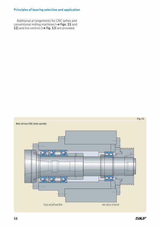
Principles of bearing selection and application
7016 ACD/P4ATBTA NN 3014 KTN/SP
Fig. 11
Belt-driven CNC lathe spindle
Additional arrangements for CNC lathes and conventional milling machines († figs. 11 and 12) and live centres († fig. 13) are provided.
58

Design considerations
N 1014 KTN/SP +BTM 70 ATN9/HCP4CDBA
N 1013 KTN/SP
Fig. 12
Conventional milling machine spindle
7209 ACD/P4AQBTBNN 3013 KTN/SP
Fig. 13
Live centre spindle
59
1

Principles of bearing selection and application
71802 ACD/P4QBTA 71802 ACD/P4DBA
Fig. 14
Multispindle drilling head
For applications where available space is limited, super-precision angular contact ball bearings in the 718 or 719 series may be more suitable († figs. 14 and 15).
60

Design considerations
S71906 CD/P4ADBA
Fig. 15
Unit for detecting defects on silicon wafer chips
61
1

Principles of bearing selection and application
7014 CE/P4AQBCA N 1011 KPHA/SP
Fig. 16
Electro-spindle in a horizontal machining centre
Bearing arrangements for greater rigidity and higher speedsWhen higher speeds are required, as is the case for high-speed machining centres (A > 1 200 000 mm/min), there is typically a com-promise between rigidity and load carrying capacity. In these applications, the spindle is usually driven directly by a motor (motorized spindles or electro-spindles), or through a coupling. Therefore, there are no radial loads on the non-tool end as is the case with a belt driven spindle. Consequently, single row angu-lar contact ball bearings mounted in sets and single row cylindrical roller bearings are fre-quently used († fig. 16). In this bearing sys-tem, the tool end bearing set is axially located, while the cylindrical roller bearing on the non-tool end accommodates thermal expansion of the spindle shaft relative to the housing within the bearing.
Other arrangement examples for spindles in high-speed machining centres and milling machines are shown in figs. 17 and 18.
If enhanced performance is required, SKF recommends using hybrid bearings equipped
with rolling elements made of bearing grade silicon nitride (Si3N4).
62

Design considerations
71922 CE/P4AQBCA 7015 CD/P4ADBB
Fig. 17
Spindle in a horizontal machining centre
7020 ACB/P4ALDT 7016 ACB/P4AL
Fig. 18
Electro-spindle in a high-speed metal cutting machine
63
1

Principles of bearing selection and application
Bearing arrangements for maximum speedWhen sets of angular contact ball bearings are mounted with a fixed preload (without springs), that preload tends to increase when in service due to differential thermal expansion. As speeds rise the significance of this effect tends to increase.
To avoid the damaging effects of excessive preload, particularly in exceptionally high speed applications (A > 2 000 000 mm/min), it is quite common to use angular contact ball bearings preloaded by springs († fig. 19). Springs control preload independent of the effects of relative thermal expansion and min-imize the amount of frictional heat generated in the bearings.
An even better solution than springs is to preload angular contact ball bearings with a hydraulic system. A hydraulic system adjusts the amount of preload according to the speed of the spindle to obtain the best combination of rigidity, frictional heat and bearing service life.
71912 CE/P4ADT 71908 CE/P4ADT
Fig. 19
Electro-spindle for an internal grinding machine
64

Design considerations
65
1

Principles of bearing selection and application
System rigiditySystem rigidity in machine tool applications is extremely important because deflection under load has a major impact on machining accur-acy. Bearing stiffness is only one factor that influences system rigidity. Others include:
• shaft stiffness • tool overhang • housing stiffness• number and position of bearings and the
influence of fits
Some general guidelines for designing high-speed precision applications include:
• Select the largest possible shaft diameter. • Minimize the distance between the tool end
bearing position and the spindle nose. • Keep the distance between the two bearing
sets short († fig. 20). A guideline for the spacing is:
l ≈ 3 … 3,5 d
wherel = distance between the first tool end
bearing row and the rearmost non-tool end bearing row
d = tool end bearing bore diameter
Diagram 9 provides an overview of the relative stiffness of different bearing systems. For de-tails about the bearing series, refer to Designation system in the relevant product chapter. The comparison is based on preloaded bear-ings with 100 mm bore on the tool end and 90 mm bore on the non-tool end. These guide-line values cannot substitute for precise sys-tem rigidity calculations. For advanced system analysis, contact the SKF application engineer-ing service.
d
l
Fig. 20
66

Design considerations
NN 3020 KTN + BTW 100 CTN9 NN 3018 KTN
NN 3020 KTN + BTM 100 BTN9/DBB NN 3018 KTN
NN 3020 KTN + BTM 100 ATN9/DBB NN 3018 KTN
NN 3020 KTN + BTM 100 ATN9/DBB N 1018 KTN
7020 CD/QBCB N 1018 KTN
71920 CE/QBCB N 1018 KTNHA
71920 ACD/TBTB NN 3018 KTN
71920 ACD/TBTB 71918 CD/DBA
7020 CD/TBTB NN 3018 KTN
7020 CD/TBTB 7018 CD/DBA
7020 ACD/TBTB 7018 CD/DBA
7020 CE/QBCB N 1018 KTNHA
7020 CE/HCDT 7018 CE/HCDT
7020 ACD/DBB 7018 CD/DBA
71920 ACE/HCTBTA 71918 CE/HCDBA
7020 CD/DT 7018 CE/DT
7020 CE/DBB N 1018 KTNHA
71920 ACE/TBTA 71918 CE/DBA
7020 ACE/HCDBA 7018 CD/HCDBA
7020 ACE/HCDBA N 1018 KTNHA/HC5
7020 ACE/TBTA 7018 CE/DBA
71920 ACE/DBA N 1018 KTNHA
71920 ACE/DBA 71918 CE/DBA
7020 ACE/DBA 7018 CE/DBA
7020 ACE/DBA N 1018 KTNHA
0 20 40 60 80 100
Tool end Non-tool end
Radial stiffnessAxial stiffness Relative stiffness [%]
Angular contact ball bearingsAC 25° contact angleC 15° contact angleD High-capacity D designE High-speed E designHC Ceramic ballsDB Two bearings, back-to-back <>DT Two bearings, tandem <<TBT Three bearings, back-to-back and tandem <>>QBC Four bearings, tandem back-to-back <<>>A Extra light or light preloadB Light or moderate preload
Cylindrical roller bearingsK Tapered boreTN PA66 cage, roller centredTNHA Glass fibre reinforced PEEK cage, outer ring centredHC5 Ceramic rollers
Double direction angular contact thrust ball bearingsA 30° contact angleB 40° contact angleC 60° contact angleTN9 Glass fibre reinforced PA66 cage, ball centred
Diagram 9
Relative stiffness of typical spindle bearing systems
67
1

Principles of bearing selection and application
Bearing stiffnessThe stiffness of a rolling bearing is character-ized by the magnitude of the elastic deform-ation (deflection) in the bearing under load. It is expressed as the ratio of load to deflection anddepends on the bearing type, design and size. The most important parameters are:
• type of rolling elements; roller bearings have a higher degree of stiffness than ball bearintgs because of the contact conditions between the rolling elements and raceways
• rolling element material († diagram 10)• number and size of rolling elements • contact angle († diagram 11)• preload class († diagram 12)
Bearing stiffness can be further enhanced by applying a preload († Bearing preload, page 90). Preloading bearings is standard practice in machine tool applications.
A loose fit on a mating component can have a negative influence on the stiffness of a bear-ing arrangement. However, a loose housing fit may be necessary for bearing arrangements
230
210
190
170
150
130
110
900 0,5 1,0 1,5 2,0 2,5 3,0
Radial stiffness [N/mm]
7007 CE/HC (ceramic balls)
7007 CE (steel balls)
Speed factor A [106 mm/min]
Diagram 10
Radial stiffness of spring preloaded bearings
using angular contact ball bearings in the non-locating position. Typically the non-locating bearing position is on the non-tool end of a spindle shaft and, therefore, the influence on system rigidity for the tool end is limited. If a high degree of stiffness is also desired for the non-tool end, a cylindrical roller bearing with a tapered bore should be used. This arrange-ment can accommodate axial displacement of the spindle shaft relative to the housing within the bearing and enables an interference fit for both the inner and outer rings.
68

Design considerations
45
40
35
30
25
20
15
10
5
00 0,4 0,8 1,2 1,6 2,0
7007 CE/DBA (a = 15°)
7007 FE/DBA (a = 18°)
7007 ACE/DBA (a = 25°)
Axial displacement [mm]
Axial load [kN]
Diagram 11
Axial displacement of back-to-back bearing sets with different contact angles
70
60
50
40
30
20
10
00 2 4 6 8 10
Axial displacement [mm]
7010 CD/DBA (extra light preload)
7010 CD/DBB (light preload)
7010 CD/DBC (moderate preload)
7010 CD/DBD (heavy preload)
Axial load [kN]
Diagram 12
Axial displacement of back-to-back bearing sets with different preload
69
1

Principles of bearing selection and application
Radial location of bearingsIf the load carrying capacity of a bearing is to be fully exploited, its rings or washers should be fully supported around their complete cir-cumference and across the entire width of the raceway. The support, which should be firm and even, can be provided by a cylindrical or tapered seat, as appropriate or, for thrust bearing washers, by a flat (plane) support sur-face. This means that bearing seats should be manufactured to adequate tolerance classes and uninterrupted by grooves, holes or other features, unless the seat is prepared for the oil injection method. This is particularly important for super-precision bearings that have rela-tively thin rings which tend to reproduce the shape of the shaft or housing seat. In addition, the bearing rings should be reliably secured to prevent them from turning on or in their seats under load.
In general, satisfactory radial location and adequate support can only be obtained when the rings are mounted with an appropriate degree of interference. Inadequately or incor-rectly secured bearing rings generally cause damage to the bearing and mating compon-ents. However, when axial displacement (as with a non-locating bearing) or easy mounting and dismounting are required, an interference fit cannot always be used. In cases where a loose fit is necessary, but an interference fit would normally be required, special precau-tions are necessary to limit the fretting wear that inevitably results from creep (the bearing ring turning on its seat). This can be done, for example, by surface hardening the bearing seat and abutments.
Recommended shaft and housing fits
Diameter tolerances for bearing seatsShaft and housing seats for super-precision angular contact ball bearings, cylindrical roller bearings and double direction angular contact thrust ball bearings should be manufactured to the diameter tolerances recommended in:
• table 7 for shaft seat tolerances• table 8 († page 72) for housing seat
tolerances
For recommendations for other super-preci-sion bearings, refer to the relevant section of:
• angular contact thrust ball bearings for screw drives († Associated components, page 349)
• axial-radial cylindrical roller bearings († Design considerations, page 324)
Values of appropriate ISO tolerance classes for super-precision bearings are listed in:
• table 9 († page 73) for shaft tolerances• table 10 († page 73) for housing
tolerances
The location of the commonly used tolerance classes relative to the bearing bore and outside diameter surface are shown in fig. 21.
70

Design considerations
Table 7
Diameter tolerances for bearing seats on steel shafts
Bearing type Shaft diameter Tolerance class1) DeviationsBearings to tolerance class
over incl. P4, P4A, P4C, SP P2, PA9A, UP high low
– mm – µm
Angular contact ball bearingswith rotating outer ring load – 400 h4 h3 – –
with rotating inner ring load – 30 – – +1 –330 80 – – +2 –380 120 – – +3 –3
120 180 – – +4 –4180 250 – – +5 –5250 315 – – +6 –6315 400 – – +6,5 –6,5
Cylindrical roller bearingswith a cylindrical bore – 40 js4 – – –
40 280 k4 – – –280 500 k42) – – –500 – Contact the SKF application engineering service.
Double direction angular contact thrust ball bearings – 200 h4 h3 – –
For hollow shafts, when A > 1 000 000 mm/min, contact the SKF application engineering service.1) All ISO tolerance classes are valid with the envelope requirement (such as h4VE ) in accordance with ISO 14405-1.2) General guideline only. SKF recommends contacting the SKF application engineering service.
+–0
+–0
h4
K4 K5
M4 M5
h3js4
k4
Transition fitInterference fit
Loose fit
Transition fitLoose fit
Interference fit
Fig. 21
71
1

Principles of bearing selection and application
Table 8
Diameter tolerances for bearing seats in cast iron and steel housings
Bearing type Conditions Housing bore Tolerance class1) DeviationsBearings to tolerance classP4, P4A, P4C, SP
P2, PA9A, UP
high lowover incl.
– – mm – µm
Angular contact ball bearings
Locating bearings, axialdisplacement of outerring unnecessary
– 18 – – +4 –118 30 – – +5 –130 50 – – +6 –150 80 – – +7 –1
80 120 – – +7 –3120 180 – – +9 –3180 250 – – +10 –4
250 315 – – +12 –4315 400 – – +13 –5400 500 – – +14 –6
Non-locating bearings,axial displacement ofouter ring desirable
– 18 – – +7 +218 30 – – +8 +230 50 – – +9 +250 80 – – +10 +2
80 120 – – +13 +3120 180 – – +16 +4180 250 – – +19 +5
250 315 – – +21 +5315 400 – – +24 +6400 500 – – +27 +7
Rotating outer ring load – 500 M5 M4 – –
Cylindrical roller bearings
Light to normal loads (P ≤ 0,1 C)
– 900 K5 K4 – –
Heavy loads (0,1 C < P ≤ 0,15 C), rotating outer ring loads
– 900 M5 M4 – –
Double direction angular contact thrust ball bearings
– 315 K5 K4 – –
1) All ISO tolerance classes are valid with the envelope requirement (such as M4VE ) in accordance with ISO 14405-1.
72

Design considerations
Table 9
Values of ISO tolerance classes for shafts
Shaft diameter Tolerance classesd h3VE h4VE js4VE k4VENominal Deviations Deviations Deviations Deviationsover incl. high low high low high low high low
mm µm
– 3 0 –2 0 –3 +1,5 –1,5 +3 03 6 0 –2,5 0 –4 +2 –2 +5 +16 10 0 –2,5 0 –4 +2 –2 +5 +110 18 0 –3 0 –5 +2,5 –2,5 +6 +1
18 30 0 –4 0 –6 +3 –3 +8 +230 50 0 –4 0 –7 +3,5 –3,5 +9 +250 80 0 –5 0 –8 +4 –4 +10 +2
80 120 0 –6 0 –10 +5 –5 +13 +3120 180 0 –8 0 –12 +6 –6 +15 +3180 250 0 –10 0 –14 +7 –7 +18 +4
250 315 0 –12 0 –16 +8 –8 +20 +4315 400 0 –13 0 –18 +9 –9 +22 +4400 500 – – – – – – +25 +5
Table 10
Values of ISO tolerance classes for housings
Housing bore diameter Tolerance classesD K4VE K5VE M4VE M5VENominal Deviations Deviations Deviations Deviationsover incl. high low high low high low high low
mm µm
10 18 +1 –4 +2 –6 –5 –10 –4 –1218 30 0 –6 +1 –8 –6 –12 –5 –1430 50 +1 –6 +2 –9 –6 –13 –5 –1650 80 +1 –7 +3 –10 –8 –16 –6 –19
80 120 +1 –9 +2 –13 –9 –19 –8 –23120 180 +1 –11 +3 –15 –11 –23 –9 –27180 250 0 –14 +2 –18 –13 –27 –11 –31
250 315 0 –16 +3 –20 –16 –32 –13 –36315 400 +1 –17 +3 –22 –16 –34 –14 –39400 500 0 –20 +2 –25 –18 –38 –16 –43
500 630 0 –22 0 –32 –26 –48 –26 –58630 800 0 –25 0 –36 –30 –55 –30 –66800 1 000 0 –28 0 –40 –34 –62 –34 –74
73
1
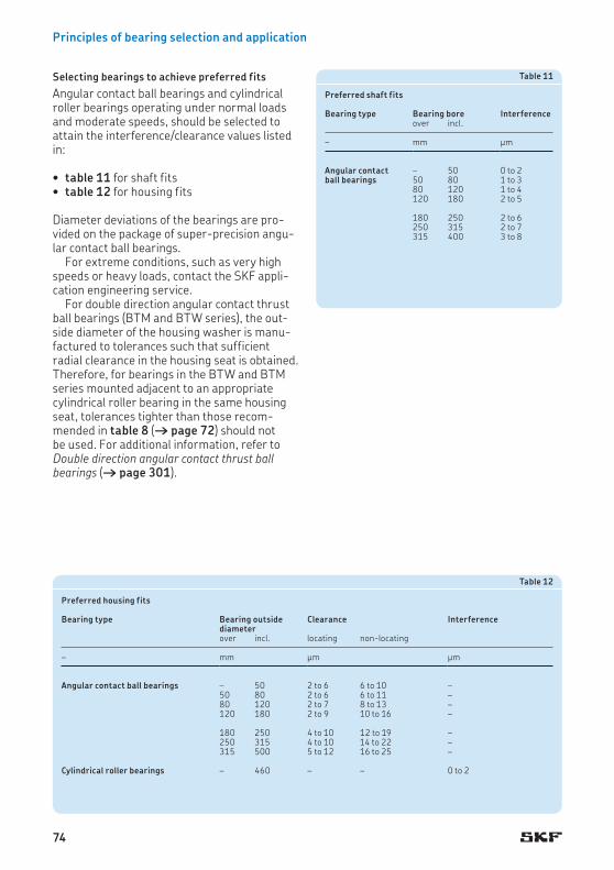
Principles of bearing selection and application
Selecting bearings to achieve preferred fitsAngular contact ball bearings and cylindrical roller bearings operating under normal loads and moderate speeds, should be selected to attain the interference/clearance values listed in:
• table 11 for shaft fits• table 12 for housing fits
Diameter deviations of the bearings are pro-vided on the package of super-precision angu-lar contact ball bearings.
For extreme conditions, such as very high speeds or heavy loads, contact the SKF appli-cation engineering service.
For double direction angular contact thrust ball bearings (BTM and BTW series), the out-side diameter of the housing washer is manu-factured to tolerances such that sufficient radial clearance in the housing seat is obtained. Therefore, for bearings in the BTW and BTM series mounted adjacent to an appropriate cylindrical roller bearing in the same housing seat, tolerances tighter than those recom-mended in table 8 († page 72) should not be used. For additional information, refer to Double direction angular contact thrust ball bearings († page 301).
Table 11
Preferred shaft fits
Bearing type Bearing bore Interferenceover incl.
– mm µm
Angular contact ball bearings
– 50 0 to 250 80 1 to 380 120 1 to 4120 180 2 to 5
180 250 2 to 6250 315 2 to 7315 400 3 to 8
Table 12
Preferred housing fits
Bearing type Bearing outside diameter
Clearance Interference
over incl. locating non-locating
– mm µm µm
Angular contact ball bearings – 50 2 to 6 6 to 10 –50 80 2 to 6 6 to 11 –80 120 2 to 7 8 to 13 –120 180 2 to 9 10 to 16 –
180 250 4 to 10 12 to 19 –250 315 4 to 10 14 to 22 –315 500 5 to 12 16 to 25 –
Cylindrical roller bearings – 460 – – 0 to 2
74

Design considerations
Accuracy of seats and abutments
Geometrical and running accuracyMaximum running accuracy, high speeds and low operating temperatures can only be achieved, even with super-precision bearings, if the mating parts and other associated com-ponents are made with equal precision as the bearings. Deviations from geometric form of associated seats and abutments should there-fore be kept to a minimum when machining mating parts. Form and position recommen-dations in accordance with ISO 1101 are pro-vided in table 13 († page 76).
Thin-walled bearing rings adapt themselves to the form of their seat. Any errors of form on the shaft or housing seat can therefore affect the bearing raceways and bearing perform-ance, e.g. angular misalignment of one bearing ring relative to the other, can cause loss of running accuracy, load concentration and high operating temperatures, particularly at high speeds.
The numerical values of IT tolerance grades in accordance with ISO 286-1 are listed in table 14 († page 77).
Surface roughnessThe surface roughness of a bearing seat does not have the same degree of influence on bearing performance as the dimensional and geometrical tolerances of the seat. However, obtaining a desired interference fit depends on the roughness of the mating surfaces, which is directly proportional to fit accuracy. Guideline values for the mean surface roughness Ra are listed in table 15 († page 77) for different bearing tolerance classes. These recommen-dations apply to ground seats.
75
1

Principles of bearing selection and application
Table 13
Geometrical tolerances for bearing seats on shafts and in housings
Surface Permissible deviationsCharacteristic Symbol Tolerance
zoneBearings to tolerance class
P4, P4A, P4C, SP P2, PA9A, UP
Cylindrical seatTotal radial run-out t3 IT2/2 IT1/2
Flat abutmentTotal axial run-out t4 IT2/2 IT1/2
Angularity t2 IT3/2 IT2/2
A B
DA DB
A-Bt4
t3 A-B
t3 A-B
A-Bt4 Bt2
AB
dA dB2 a
a = 2° 23' 9,4"
76

Design considerations
Table 14
Values of ISO tolerance grades
Nominal dimension Tolerance gradesIT0 IT1 IT2 IT3 IT4 IT5
over incl. max.
mm µm
– 3 0,5 0,8 1,2 2 3 43 6 0,6 1 1,5 2,5 4 56 10 0,6 1 1,5 2,5 4 6
10 18 0,8 1,2 2 3 5 818 30 1 1,5 2,5 4 6 930 50 1 1,5 2,5 4 7 11
50 80 1,2 2 3 5 8 1380 120 1,5 2,5 4 6 10 15120 180 2 3,5 5 8 12 18
180 250 3 4,5 7 10 14 20250 315 4 6 8 12 16 23315 400 5 7 9 13 18 25
400 500 6 8 10 15 20 27500 630 – 9 11 16 22 32630 800 – 10 13 18 25 36800 1 000 – 11 15 21 28 40
Table 15
Surface roughness of bearing seats
Seat diameter Recommended Ra value for ground seatsShaft Housing boreBearings to tolerance class Bearings to tolerance classP4, P4A, P4C, SP P2, PA9A, UP P4, P4A, P4C, SP P2, PA9A, UP
over incl. max. max.
mm µm µm
– 80 0,2 0,1 0,4 0,480 250 0,4 0,2 0,4 0,4250 500 0,8 0,4 0,8 0,8
500 800 0,8 0,8 0,8 0,8 800 1 000 0,8 0,8 1,6 1,6
77
1

Principles of bearing selection and application
Axial location of bearingsIn general, an interference fit alone is in ad-equate to locate a bearing ring on a cylindrical seat. Under load, a bearing ring can wander on its seat. Some suitable means to secure the bearing axially is needed.
For a locating bearing, both rings should be secured axially on both sides.
For non-separable bearings in the non-locating position, the ring with an interference fit, typically the inner ring, should be secured axially on both sides. The other ring must be free to move axially on its seat to accommo-date axial displacement.
Cylindrical roller bearings in the non-locat-ing position are exceptions. The inner and outer rings of these bearings must be secured axially in both directions.
In machine tool applications, bearings at the tool end generally locate the shaft by transmit-ting the axial load from the shaft to the hous-ing. In general, then, tool end bearings are located axially, while non-tool end bearings are axially free.
Locating methods
Lock nutsBearing inner rings that are mounted with an interference fit typically abut a shoulder on the shaft on one side. On the opposite side, they are normally secured by a precision lock nut († fig. 22).
Bearings with a tapered bore, mounted directly on a tapered shaft seat, are generally retained on the shaft by a spacer seated against a fixed abutment at the large end of the taper and a precision lock nut at the small end of the taper. The spacer width is adjusted to limit the drive-up distance of the bearing on its tapered seat.
For detailed information about precision lock nuts, refer to Precision lock nuts († page 375).
Spacer sleevesInstead of integral shaft or housing shoulders, spacer sleeves or collars can be used between the bearing rings or between a bearing ring and an adjacent component († fig. 23). In these cases, the dimensional and form toler-ances for abutments apply.
Fig. 22 Fig. 23
78

Design considerations
Stepped sleevesAnother way to locate a bearing axially is to use a stepped sleeve († fig. 24) with a tight inter-ference fit on the shaft. These sleeves are par-ticularly suitable for super-precision bearing arrangements, as they have very small run-out and provide superior accuracy compared to threaded lock nuts. Therefore, stepped sleeves are typically used in very high-speed spindles where the accuracy provided by conventional locking devices may be inadequate.
For detailed information about stepped sleeves, refer to Stepped sleeves († page 80).
Fig. 24
D
Axial gap
Fig. 25
Housing coversBearing outer rings that are mounted with an interference fit typically abut a shoulder in the housing on one side. On the opposite side, they are normally located by a housing cover.
Housing covers and their securing screws can, in some cases, have a negative impact on bearing form and performance. If the wall thickness between the bearing seat and the bolt holes is too small, and/or the bolts are tightened too much, the outer ring raceway may deform. Bearings in the lightest ISO dimension series 18 and 19 are more suscep-tible to this than those in the ISO dimension series 10 or above.
It is advisable to use a larger number of small diameter bolts. Using only three or four bolts should be avoided because a small num-ber of tightening points may produce lobes in the housing bore. This can result in noise, vibration, unstable preload or premature fail-ure due to load concentrations. For complex spindle designs where space is limited, only thin-section bearings and a limited number of bolts may be possible. In these cases, SKF rec-ommends an FEM (finite element method) analysis to accurately predict deformation.
In addition, the axial gap between the hous-ing side face and the flange of the cover should be checked after the bolts are tightened. A guideline value is 10 to 15 µm per 100 mm housing bore diameter († fig. 25).
79
1

Principles of bearing selection and application
Stepped sleevesStepped sleeves are pressure joints with two slightly different inside diameters that mate with a stepped shaft. An interference fit main-tains the sleeve’s position axially and deter-mines its axial load carrying capacity. The stepped design of the fitting surface simplifies alignment during mounting but also facilitates dismounting when using the oil injection method.
Stepped sleeves do not create any stresses that might reduce the running accuracy of a shaft, but do enhance shaft stiffness. They are typically used in very high speed, lightly loaded applications where there are minimal shock loads. Compared to threaded lock nuts, stepped sleeves provide superior mounting ac-curacy, provided the sleeve and its seats are manufactured to the appropriate specifica-tions, and the sleeve is mounted correctly.
SKF does not supply or manufacture stepped sleeves, but design recommendations and suitable dimensions are provided on the pages that follow.
DesignsStepped sleeves († fig. 26) can have either a conventional sleeve form (a) or they can be ring shaped (b). Ring-shaped stepped sleeves are typically used in applications where the sleeve will also be used to form part of a laby-rinth seal († Special stepped sleeve designs, page 84).
In applications where there are relatively light axial loads, the end of the sleeve with the smaller diameter can have a loose fit on the shaft. However, if the oil injection method will be used to dismount the sleeve, the end of the sleeve with the loose fit should be sealed with an O-ring (c).
a
b
c
Fig. 26
80

Design considerations
Recommended dimensionsRecommended dimensions are listed in:
• table 16 († page 82) for stepped sleeves (without O-ring) and their seats (bearing arrangement example † fig. 27)
• table 17 († page 83) for stepped sleeves with O-ring and their seats (bearing arrangement example † fig. 28)
When machining bores and shaft seats for stepped sleeves, it is very important that the actual degree of interference fit is as close as possible for both the major and minor diam-eters. Experience has shown that removal becomes much more difficult when there is even a small difference in interference.
Fig. 28
Fig. 27
Thin-walled hollow shafts may deform as a result of high contact pressures. Therefore, the sleeves for these shafts should have a relief closest to the bearing to avoid deformation of the bearing seat. The length of the relief should be 15 to 20% of the shaft diameter.
81
1

Principles of bearing selection and application
Table 16
Recommended dimensions for stepped sleeves and their seats
Dimensions Temperature difference1)Shaft Stepped sleeve
d1 d2 d3 d4 d5 D B1 B2 B3 L1 L2h4VE h4VE H4VE H4VE +0,5 j13VE J13VE
mm °C °F
17 16,968 16,95 16,977 19 27 26 31 13 15 8,5 150 27020 19,964 19,94 19,971 22 30 28 33 14 16 9 150 27025 24,956 24,92 24,954 27 35 30 35 15 17 9,5 150 270
30 29,946 29,91 29,954 32 40 32 38 16 18 10 140 25235 34,937 34,9 34,943 37 47 34 40 17 19 10,5 140 25240 39,937 39,9 39,943 42 52 36 42 18 20 11 130 234
45 44,927 44,88 44,933 47 58 38 46 19 21 11,5 130 23450 49,917 49,86 49,923 52 63 40 48 20 22 12 130 23455 54,908 54,85 54,922 57 70 42 50 21 23 12,5 120 216
60 59,908 59,85 59,922 62 75 44 54 22 24 13 120 21665 64,898 64,83 64,912 67 80 46 56 23 25 13,5 120 21670 69,898 69,83 69,912 72 86 48 58 24 26 14 110 198
75 74,898 74,83 74,912 77 91 50 60 25 27 14,5 100 18080 79,888 79,82 79,912 82 97 52 62 26 28 15 100 18085 84,88 84,81 84,9 87 102 54 64 27 29 15,5 100 180
90 89,88 89,8 89,9 92 110 56 68 28 30 16 100 18095 94,87 94,79 94,9 97 114 58 70 29 31 16,5 90 162100 99,87 99,79 99,9 102 120 60 72 30 32 17 90 162
105 104,87 104,78 104,89 107 125 62 74 31 33 17,5 90 162110 109,86 109,77 109,89 112 132 64 76 32 34 18 90 162120 119,86 119,77 119,89 122 142 68 80 34 36 19 80 144
130 129,852 129,75 129,868 132 156 72 84 36 38 20 90 162140 139,852 139,74 139,858 142 166 76 88 38 40 21 90 162150 149,842 149,73 149,858 152 180 80 95 40 42 22 80 144
160 159,842 159,73 159,858 162 190 84 99 42 44 23 80 144170 169,842 169,72 169,848 172 205 88 103 44 46 24 80 144180 179,832 179,71 179,848 182 220 92 110 46 48 25 80 144
190 189,834 189,7 189,836 192 230 96 114 48 50 26 80 144200 199,834 199,7 199,836 202 245 100 118 50 52 27 70 126
1) The difference in temperature between shaft and sleeve or ring when installing2) L3 = length of stepped sleeve over diameter d1 = L1 + B2 – B1 – 4 [mm]3) L4 = length of stepped ring over diameter d1 = L2 – 4 + recessed d4 section [mm]
L23)
L1L32)
d2d1
L4
d5 d4
B2
B1
L1
d3D
4
M 4×0,5
24
0,5M 4×0,5
d4
L2
d3
B3
8
0,5
5
D 4
2
82

Design considerations
Table 17
Recommended dimensions for stepped sleeves with O-ring and their seats
Dimensions Appropriate O-ring
Temperature difference1)Shaft Stepped sleeve
d1 d2 L1 d3 d4 d5 D B1 B2 L2 L3 L4h4VE f7VE j13 H4VE +0,5 H9 j13VE +0,2
mm – °C °F
17 16,95 17 16,977 19 20,6 27 26 31 22,9 6,5 3,1 16,3x2,4 150 27020 19,95 19 19,971 22 23,6 30 28 33 24,9 6,5 3,1 19,3x2,4 150 27025 24,9 21 24,954 27 29,5 35 30 35 26,1 7 3,9 24,2x3 150 270
30 29,9 24 29,954 32 34,5 40 32 38 28,1 7 3,9 29,2x3 140 25235 34,9 26 34,943 37 39,5 47 34 40 30,1 7 3,9 34,2x3 140 25240 39,9 28 39,943 42 44,5 52 36 42 32,1 7 3,9 39,2x3 130 234
45 44,9 32 44,933 47 49,5 58 38 46 34,1 7 3,9 44,2x3 130 23450 49,9 34 49,923 52 54,5 63 40 48 36,1 7 3,9 49,2x3 130 23455 54,9 36 54,922 57 59,5 70 42 50 38,1 7 3,9 54,2x3 120 216
60 59,9 40 59,922 62 64,5 75 44 54 40,1 7 3,9 60x3 120 21665 64,85 42 64,912 67 69,5 80 46 56 42,1 7 3,9 65x3 120 21670 69,85 42 69,912 72 74,5 86 48 58 44,1 8 3,9 69,5x3 110 198
75 74,85 44 74,912 77 79,5 91 50 60 46,1 8 3,9 74,5x3 100 18080 79,85 46 79,912 82 84,5 97 52 62 48,1 8 3,9 79,5x3 100 18085 84,85 48 84,9 87 89,5 102 54 64 50,1 8 3,9 85x3 100 180
90 89,85 52 89,9 92 94,5 110 56 68 52,1 8 3,9 90x3 100 18095 94,85 54 94,9 97 99,5 114 58 70 54,1 8 3,9 94,5x3 90 162100 99,85 54 99,9 102 104,5 120 60 72 56,1 9 3,9 100x3 90 162
105 104,85 56 104,89 107 109,5 125 62 74 58,1 9 3,9 105x3 90 162110 109,85 58 109,89 112 114,5 132 64 76 60,1 9 3,9 110x3 90 162120 119,85 62 119,89 122 124,5 142 68 80 64,1 9 3,9 120x3 80 144
130 129,8 66 129,868 132 134,4 156 72 84 68,1 9 3,9 130x3 90 162140 139,8 70 139,858 142 144,4 166 76 88 72,1 9 3,9 140x3 90 162150 149,8 73 149,858 152 159 180 80 95 72,6 13 7,4 149,2x5,7 80 144
160 159,8 77 159,858 162 169 190 84 99 76,6 13 7,4 159,2x5,7 80 144170 169,8 81 169,848 172 179 205 88 103 80,6 13 7,4 169,2x5,7 80 144180 179,8 88 179,848 182 189 220 92 110 84,6 13 7,4 179,2x5,7 80 144
190 189,8 92 189,836 192 199 230 96 114 88,6 13 7,4 189,2x5,7 80 144200 199,8 96 199,836 202 209 245 100 118 92,6 13 7,4 199,2x5,7 70 126
1) The difference in temperature between shaft and sleeve when installing2) L5 = length of stepped sleeve over diameter d1 = L1 + B2 – B1 – 4 [mm]
B2
B1
2
4d3
L1 L4
L3
d4D d5
4
0,5
M 4×0,5
L2
d2
L2L52)
d1
83
1

Principles of bearing selection and application
MaterialSKF recommends using a heat-treatable steel with a yield point of at least 550 N/mm2. The mating surfaces of both the sleeve and shaft should be hardened and ground.
Axial load carrying capacityThe degree of the actual interference fit(s) determines the axial load carrying capacity of a stepped sleeve. When stepped sleeves are made to the recommended dimensions listed in tables 16 and 17 († pages 82 and 83), the surface pressure between a solid or thick-walled hollow shaft and sleeve, and the axial retaining force per millimetre hub width can be estimated using the approximate values listed in table 18. Stepped sleeves with a loose fit for the smaller diameter, exert only half of the axial retaining force of stepped sleeves with an interference fit for both diameters.
When designing stepped sleeves, axial shock forces on the sleeve must also be taken into consideration. If necessary, a threaded nut
which is lightly tightened and which can also serve as a mounting aid can be used to secure the sleeve.
Special stepped sleeve designsStepped sleeves are used to secure and join other components. They enable hubs to be mounted and dismounted simply and can also replace various types of driver plates, dogs etc. The V-belt pulley shown in fig. 29, for exam-ple, is designed as a stepped sleeve with an integral labyrinth seal. In this case, the sleeve not only locates the bearing axially, it is also used to transmit torque.
Fig. 29
84

Design considerations
Table 18
Approximate surface pressure and axial retaining force of stepped sleeves1)
Approximate shaft diameter
Approximate surface pressure
Approximate axial retaining force per mm hub widthd
mm N/mm2 N/mm
30 40 300100 35 550200 22 1 000
1) When made to the recommended dimensions listed in tables 16 and 17 († pages 82 and 83).
85
1

Principles of bearing selection and application
Fig. 30
InstallationThe following procedure can be used to mount stepped sleeves. If stepped sleeves are to be mounted against bearings that are already greased, care should be taken that the injected oil / mounting fluid does not mix with the grease and impair its lubricating properties.
1 Heat the sleeve to obtain the required tem-perature difference listed in tables 16 and 17 († pages 82 and 83).
2 Push the sleeve onto the shaft seat.3 After the sleeve has cooled, inject oil or an
SKF mounting fluid between the sleeve and shaft using suitable oil injection equipment († fig. 30 and Oil injection equipment and pressure media). To avoid local stress peaks, the oil should be injected slowly and the oil pressure regulated.
4 Use a hydraulic nut and suitable distance sleeve to bring the sleeve to its final position († fig. 30). When using a hydraulic nut, the force of the nut against the bearing arrange-ment can be controlled by the oil pressure. As the sleeve “floats” on the oil film, any stresses produced during the shrinking of the sleeve (produced as the sleeve cooled) are relieved and the components can be cor-rectly positioned relative to each other. When the required axial force has been obtained, the final position is reached.
5 With the tool still in position, release the oil pressure between the mating surfaces and allow the oil to drain. Normally it takes about 24 hours before the sleeve can support its full load.
86

Design considerations
Removal To remove a stepped sleeve, inject oil or an SKF dismounting fluid between the sleeve and shaft using suitable oil injection equipment († Oil injection equipment and pressure media). When sufficient oil pressure has been built up to sep-arate the mating surfaces, an axial force will result due to the different bore diameters, and the sleeve will slide from its seat without requiring any additional external force.
Oil injection equipment and pressure mediaSKF supplies oil injection equipment for install-ing and removing sleeves. For additional infor-mation, visit skf.com/mapro.
When selecting a suitable pump, keep in mind that the maximum permissible pressure should be considerably higher than the calcu-lated surface pressure.
For installation, SKF recommends using the SKF mounting fluid LHMF 300. The fluid has a viscosity of 300 mm2/s at 20 °C (70 °F). The advantage of this mounting fluid is that when mounting is complete, the fluid will leave the joint quickly and completely so that metal-to-metal contact is restored relatively quickly.
For removal, SKF recommends using the SKF dismounting fluid LHDF 900. With a vis-cosity of 900 mm2/s at 20 °C (70 °F), the fluid will provide an adequate oil film, even if the mating surface of the sleeve or shaft is scratched. Keep in mind that the fluid has a low flow rate and the permissible pressure of the oil injection equipment should never be exceeded.
WARNINGTo avoid the risk of serious injury, attach a provision such as a lock nut to the shaft end to limit the sleeve travel when it sud-denly comes loose.
87
1

Principles of bearing selection and application
Provisions for mounting and dismountingIt is often necessary to make provisions during the design stage to facilitate mounting and dis-mounting of a bearing. If, for example, slots or recesses are machined in the shaft and/or housing shoulders, it is possible to apply with-drawal tools († fig. 31). Threaded holes in the housing shoulders also enable the use of bolts to push a bearing from its seat († fig. 32).
If the oil injection method is to be used to mount or dismount bearings on a tapered seat, or to dismount bearings from a cylindrical seat, ducts and grooves should be provided in the shaft († fig. 33). Recommended dimensions for the appropriate grooves, ducts and threaded holes to connect the oil supply are listed in tables 19 and 20.
Fig. 31
Fig. 32
Fig. 33
88

Design considerations
Table 19
Recommended dimensions for oil supply ducts and distribution grooves
Seat diameter Dimensionsba ha ra N
over incl.
mm mm
– 50 2,5 0,5 2 250 100 3 0,5 2,5 2,5100 150 4 0,8 3 3
150 200 4 0,8 3 3200 250 5 1 4 4250 300 5 1 4 4
300 400 6 1,25 4,5 5400 500 7 1,5 5 5500 650 8 1,5 6 6
650 800 10 2 7 7
L3
L
N
ha
ra
ba
L = width of bearing seat
Table 20
Design and recommended dimensions for threaded holes for connecting oil supply
Thread Design DimensionsGa Gb Gc
1) Namax.
– – mm
M 4x0,5 A 5 4 2
M 6 A 10 8 3
G 1/8 A 12 10 3
G 1/4 A 15 12 5
G 3/8 B 15 12 8
G 1/2 B 18 14 8
G 3/4 B 20 16 8
Na Ga
Gc
Gb
Na Ga
Gc
Gb
60°
Design A Design B
1) Effective threaded length
89
1

Principles of bearing selection and application
Bearing preload Preload is a force acting between the rolling elements and bearing rings that is not caused by an external load. Preload can be regarded as negative internal clearance. Reasons to apply preload include:
• enhanced stiffness• reduced noise level• improved shaft guidance• extended bearing service life• improved running accuracy• prevent skidding in high-speed applications
during rapid starts and stops and under very light or no-load conditions
In the majority of high-precision applications, preload is needed to enhance system rigidity.
Angular contact ball bearingsSingle row angular contact ball bearings are generally mounted as sets, in a back-to-back († figs. 34 and 35) or face-to-face arrange-ment († fig. 36), that are normally subjected to an axial preload. The preload is produced by displacing one bearing ring axially, relative to the other († figs. 34 and 36), by an amount corresponding to the desired preload force or by springs († fig. 35).
The standout of matched and universally matchable bearings is precision ground so that when two bearings are mounted immediately adjacent to each other, a given preload is obtained without further adjustment. Keep in mind that this preload is also influenced by the interference fit and the operating conditions. For additional information, refer to Preload in mounted bearing sets († page 162).
If it is necessary to change the preload, spacers between the bearing rings can be used. For additional information, refer to Individual adjustment of preload († page 166).
Fig. 34
Fig. 35
Fig. 36
90

Design considerations
Influence of an external load on preloaded bearing setsThe influence of an external axial load on preloaded bearing sets is illustrated in diagram 13. The curves represent the spring characteristics of two bearings in a back-to-back arrangement. The blue curve represents bearing A, which is subjected to an external axial force Ka. The red curve represents bear-ing B, which becomes unloaded by the axial force.
The two bearings are each preloaded by an axial displacement d0 of one bearing ring rela-tive to the other, resulting in a preload force F0 acting on both bearings. When bearing A is subjected to an external axial force Ka, the load on that bearing increases to FaA while load on bearing B decreases to FaB. Axial displacement of the bearing rings follows the spring curves. dKa is the displacement of the bearing set while dKb is the remaining preload [µm] on bearing B.
When the axial forces on the spindle reach the natural lifting force Ka1, bearing B becomes completely unloaded. When this happens, there is a significant risk that the unloaded balls stop rolling and start skidding, which if it occurs for any length of time will result in pre-mature bearing failure.
Diagram 13
Influence of an external load on preloaded bearing sets
dKa dKb
Ka
Ka
A B
Ka1
d0
FaA
F0
FaB
Axial load Fa,preload force F0
Axial displacement
Bearing B Bearing A
The lifting force varies depending on the preload and bearing arrangement († table 21, page 92). It is possible to avoid the lifting force phenomena in one of two ways: either increase the preload, or use bearing sets with different contact angles. For additional information, contact the SKF application engin-eering service.
91
1

Principles of bearing selection and application
Table 21
Lifting forces for angular contact ball bearing sets
Arrangement Lifting forces Ka1 Kb1
2,83 F0 2,83 F0
4,16 F0 2,08 F0
2,83 F0 2,83 F0
5,4 F0 1,8 F0
5,9 F0 1,75 F0
9,85 F0 1,45 F0
5,9 F0 1,75 F0
13,66 F0 1,33 F0
F0 = preload force
A B
Ka1 Kb1
A A B
Ka1 Kb1
A A B B
Ka1 Kb1
A A A B
Ka1 Kb1
A B
Ka1 Kb1
A A B
Ka1 Kb1
A A B B
Ka1 Kb1
A A A B
Ka1 Kb1
Same contact angles (aA = aB)
Different contact angles (aA = 25°, aB = 15°)
92

Design considerations
Preloading with springsUsing springs to apply preload to angular con-tact ball bearings is common, especially in high-speed grinding spindles. The springs act on the outer ring of one of the two bearings. This outer ring must be able to be displaced axially. The preload force remains practically constant, even when there is axial displace-ment of the bearing as a result of thermal shaft expansion. For additional information concern-ing preloading with springs and values for preload force, refer to Preload with constant force († page 165).
Preloading with springs is not suitable for applications where a high degree of stiffness is required, where the direction of load changes, or where indeterminate shock loads can occur.
93
1

Principles of bearing selection and application
Cylindrical roller bearingsCylindrical roller bearings can only be preloaded radially († fig. 37). Bearings with a tapered bore are preloaded by driving the bearing inner ring up onto its tapered seat. The resulting interference fit causes the inner ring to expand and to obtain the necessary preload. To accurately set preload, internal clearance gauges should be used. For additional informa-tion, refer to Mounting († page 280) or Adjusting for clearance or preload († page 278).
Angular contact thrust ball bearingsAngular contact thrust ball bearings can only be preloaded axially († fig. 38). The standout of angular contact thrust ball bearings is preci-sion ground so that when the two halves of the bearing are assembled, a given preload is obtained without further adjustment. Keep in mind that preload is also influenced by the interference fit and the operating conditions.
Under load, angular contact thrust ball bearings exhibit similar characteristics as angular contact ball bearings. Therefore, the information provided for angular contact ball bearings is also valid for these bearings. The lifting force for single direction angular contact thrust ball bearings for screw drives in the BSA and BSD series is the same as for angular con-tact ball bearings († table 21, page 92).
For double direction angular contact thrust ball bearings in the BTW and BTM series, the lifting force can be estimated from
Ka1 = 2,85 F0
whereKa1 = lifting forceF0 = preload on bearings before external axial
load is applied
Fig. 37
Fig. 38
94

Design considerations
Sealing solutionsContaminants and moisture can negatively affect bearing service life and performance. This is particularly important for machine tool applications where coolant and swarf are an integral part of the operating environment. Therefore, an effective sealing arrangement is essential if a spindle is to operate reliably. To protect the bearings, SKF offers a wide assort-ment of external and integral seals.
External sealsFor bearing arrangements where the effec-tiveness of the seal under specific operating conditions is more important than space con-siderations or cost, there are two types of external seals available: non-contact seals
(† fig. 39) and contact seals († fig. 41, page 98).
For seals that are not supplied by SKF, the information provided in the following section should be used as a guideline only. Make sure to understand the seal’s performance criteria before incorporating that seal into an applica-tion. SKF does not accept liability for the per-formance of any products not supplied by SKF.
Fig. 39
95
1

Principles of bearing selection and application
Non-contact sealsNon-contact seals are almost always used in high-speed precision applications. Their effect-iveness depends, in principle, on the sealing action of the narrow gap between the shaft and housing. Because there is no contact, these seals generate almost no friction and do not, in practice, limit speeds, making them an excellent solution for machine tool applications.
Seal variants range from simple gap-type seals to multi-stage labyrinth seals († fig. 39, page 95). Compared to gap-type seals, multi-stage labyrinth seals are considerably more effective as their series of axially and radially intersecting components make it more difficult for contaminants and cutting fluid to enter the bearing.
In highly contaminated environments, a complex labyrinth seal design is often required. Labyrinth seals can have three or more stages to keep lubricant in and contaminants out of the bearing arrangement. The principle of a highly effective labyrinth seal, outlined in fig. 40, consists of three stages:
• the primary stage• the secondary stage• the final stage
This design, with drainage chambers and col-lecting provisions, is derived from studies done by the Technical University of Stuttgart, Germany.
The primary stage consists of a splash guard (1), a housing cover (2) and the shaft to form a labyrinth. The splash guard uses centrifugal force to direct contaminants away from the cover, while the housing cover prevents con-taminants from entering the labyrinth directly. A radial gap (3) between the housing cover and the shaft should be between 0,1 and 0,2 mm.
The secondary stage is designed to collect any fluid that manages to pass the primary barrier and drain it away. Starting with annular groove(s) in the shaft (4), the main design fea-tures of this stage include a large drainage chamber (5) and an outlet hole (6). Annular groove(s) deter fluid from travelling along the shaft under non-rotating conditions, causing it to drip into the drainage chamber instead. When the shaft is rotating, fluid is flung from it and collected in the drainage chamber and drained through the outlet hole. Large drain-
age holes (~ 250 mm2) in the collection area limit the amount of fluid that collects in the chamber.
Features used in the previous stages are incorporated again in the final stage. This sec-tion consists of labyrinth rings (7) with radial gaps between 0,2 and 0,3 mm, a fluid retard-ation chamber (8), a collector (9) to guide the fluid toward the drainage area and an outlet hole (10) with a drainage area of ~ 150 mm2. An additional chamber, collector and a ~ 50 mm2 drainage hole (11) can be incorpor-ated if space permits. A final radial labyrinth gap (12) of ~ 1 mm avoids capillary action.
When designing these types of sealing arrangements, the following should be taken into consideration:
• In order to avoid inward pumping effects, the labyrinth components should progres-sively decrease in diameter from the outside.
• Machine lead on rotating components can move fluids in either axial direction very effectively depending on the hand of the lead and the direction of rotation. This can, in uni-directional applications, be exploited to reinforce the effectiveness of gap or laby-rinth seals if carefully incorporated into the design. Machine lead on rotating compon-ents of gap and labyrinth seals should be avoided when the application rotates in both directions or for uni-directional applications where its action would work against the effectiveness of the seal.
• Under severe operating conditions, an air barrier can be created by applying air, under pressure, between the labyrinth gaps or inside the spindle itself. The air flow must however be balanced so that the dominant flow is always outward.
• A sealing system that takes up considerable axial space is favourable, as this enables large drainage areas and collectors to be incorporated into the system. In these cases, however, the spindle is less rigid as a result of the long overhang from the front bearings (and cutting force position).
96

Design considerations
2
1
3
4
5 7 8 9 11 12
6
10
Fig. 40
97
1

Principles of bearing selection and application
Contact sealsContact seals († fig. 41) are generally very reliable. Their effectiveness, however, depends on a number of factors including:
• the seal design• the seal material• the contact pressure• the surface finish of the seal counterface• the condition of the seal lip• the presence of lubricant between the seal
lip and counterface
Friction between the seal lip and counterface can generate a significant amount of heat at higher speeds (A ≥ 200 000 mm/min). As a result, these seals can only be used in slower speed spindles and/or in applications where the additional heat does not significantly affect spindle performance.
Fig. 41
Integral sealsSealed bearings are generally used for arrangements where a sufficiently effective external sealing solution cannot be provided for cost reasons or because of space limitations.
SKF supplies a wide assortment of super-precision bearings fitted with a seal on each side. For details, refer to Sealing solutions in the relevant product chapter.
98
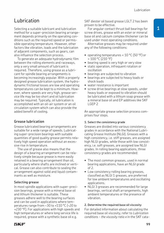
Lubrication
LubricationSelecting a suitable lubricant and lubrication method for a super-precision bearing arrange-ment depends primarily on the operating con-ditions such as the required speed or permis-sible operating temperature. However, other factors like vibration, loads and the lubrication of adjacent components, such as gears, can also influence the selection process.
To generate an adequate hydrodynamic film between the rolling elements and raceways, only a very small amount of lubricant is required. Therefore, using grease as a lubri-cant for spindle bearing arrangements is becoming increasingly popular. With a properly designed grease lubrication system, the hydro-dynamic frictional losses are low and operating temperatures can be kept to a minimum. How-ever, where speeds are very high, grease ser-vice life may be too short and oil lubrication may be required. Typically, oil lubrication is accomplished with an oil-air system or an oil circulation system which can also provide the added benefit of cooling.
Grease lubricationGrease lubricated bearing arrangements are suitable for a wide range of speeds. Lubricat-ing super-precision bearings with suitable quantities of good quality grease permits rela-tively high speed operation without an exces-sive rise in temperature.
The use of grease also means that the design of a bearing arrangement can be rela-tively simple because grease is more easily retained in a bearing arrangement than oil, particularly where shafts are inclined or verti-cal. Grease can also contribute to sealing the arrangement against solid and liquid contam-inants as well as moisture.
Selecting greaseIn most spindle applications with super-preci-sion bearings, grease with a mineral base oil and lithium thickener is suitable. These greases adhere well to the bearing surfaces and can be used in applications where tem-peratures range from –30 to +110 °C (–20 to +230 °F). For applications with high speeds and high temperatures or where long service life is required, grease with a synthetic base oil e.g.
SKF diester oil based grease LGLT 2 has been proven to be effective.
For angular contact thrust ball bearings for screw drives, grease with an ester or mineral base oil and calcium complex thickener can be used under most operating conditions.
Alternative greases may be required under any of the following conditions:
• operating temperatures < 10 °C (50 °F) or > 100 °C (210 °F)
• bearing speed is very high or very slow • static operation, infrequent rotation or
oscillation• bearings are subjected to vibration• bearings are subjected to heavy loads or
shock loads• water resistance is important• screw drive bearings at slow speeds, under
heavy loads or exposed to vibration should be lubricated with a lithium soap grease with a mineral base oil and EP additives like SKF LGEP 2
An appropriate grease selection process com-prises four steps.
1. Select the consistency gradeGreases are divided into various consistency grades in accordance with the National Lubri-cating Grease Institute (NLGI). Greases with a high consistency, i.e. stiff greases, are assigned high NLGI grades, while those with low consist-ency, i.e. soft greases, are assigned low NLGI grades. In rolling bearing applications, three consistency grades are recommended:
• The most common greases, used in normal bearing applications, have an NLGI grade of 2.
• Low consistency rolling bearing greases, classified as NLGI 1 greases, are preferred for low ambient temperatures and oscillating applications.
• NLGI 3 greases are recommended for large bearings, vertical shaft arrangements, high ambient temperatures or the presence of vibration.
2. Determine the required base oil viscosityFor detailed information about calculating the required base oil viscosity, refer to Lubrication conditions the viscosity ratio k in the SKF cata-
99
1

Principles of bearing selection and application
logue Rolling bearings or at skf.com. The graphs in this catalogue are based on the elasto-hydrodynamic theory of lubrication (EHL) with full-film conditions.
It has been found, however, that when using greases containing very low or very high vis-cosity base oils, a thinner oil film than that pre-dicted by EHL theories results. Therefore, when using the graphs to determine the required base oil viscosity for grease lubricated super-precision bearings, corrections may be necessary. From practical experience, deter-mine the required viscosity n at reference tem-perature 40 °C (150 °F) and then adjust as follows:
• n ≤ 20 mm2/s † multiply the viscosity by a factor of 1 to 2In this low range, the viscosity of the oil is too thin to form a sufficiently thick oil film.
• 20 mm2/s < n ≤ 250 mm2/s † no correction factor is used
• n > 250 mm2/s † contact the SKF applica-tion engineering service
Calculations can also be made using the SKF program, Viscosity, available online at skf.com/bearingcalculator.
High viscosity greases increase friction and heat generated by the bearing but may be necessary, for example, for ball screw support bearings in slow speed applications or in appli-cations where there is a risk of false brinelling.
3. Verify the presence of EP additivesGrease with EP additives may be appropriate if super-precision bearings are subjected to any of the following conditions:
• very heavy loads (P > 0,15 C)• shock loads• slow speeds• periods of static loading• frequent starts and stops during a work
cycle
Lubricants with EP additives should only be used when necessary and always within their operating temperature range. Some EP addi-tives are not compatible with bearing materials particularly at higher temperatures. For add-itional information, contact the SKF application engineering service.
4. Check additional requirementsIn some applications, operating conditions may put additional requirements on the grease, requiring it to have unique characteristics. The following recommendations are provided as guidelines:
• For superior resistance to water wash-out, consider grease with a calcium thickener over a lithium thickener.
• For good rust protection, select an appropri-ate additive.
• If there are high vibration levels, choose grease with a high mechanical stability.
To select the appropriate grease for a specific bearing type and application, the grease selec-tion program, SKF LubeSelect, available online at skf.com/lubrication, can be used.
100

Lubrication
Initial grease fillSuper-precision bearings operating at high speeds should have less than 30% of the free space in the bearings filled with grease.
Open angular contact thrust ball bearings for screw drives should be lubricated with a grease quantity that fills ~ 25 to 35% of the free space in the bearing.
Freshly greased bearings should be oper-ated at slow speeds during the running-in period († Runningin of grease lubricated bearings, page 111). This enables excess grease to be displaced and the remainder to be evenly distributed within the bearing. If this running-in phase is neglected, there is a risk that temperature peaks can lead to premature bearing failure.
The initial grease fill depends on the bearing type, series and size as well as the speed factor A.
A = n dm
whereA = speed factor [mm/min]dm = bearing mean diameter [mm]
= 0,5 (d + D) n = rotational speed [r/min]
The initial grease fill for open bearings can be estimated using
G = K Gref
whereG = initial grease fill [cm3]Gref = reference grease quantity [cm3]
– for angular contact ball bearings † table 22, page 102
– for cylindrical roller bearings † table 23, page 103
– for double direction angular contact thrust ball bearings † table 24, page 104
– for single direction angular contact thrust ball bearings for screw drives † table 25, page 104
K = a calculation factor dependent on the bearing type and the speed factor A († diagram 14, page 105)
Sealed bearings are filled with a high grade, low viscosity grease that fills ~ 15% of the free space in the bearing. They are considered to be relubrication-free under normal operating conditions. The grease is characterized by:
• high-speed capability• excellent resistance to ageing• very good rust inhibiting properties
The technical specifications of the grease are listed in table 26, page 104.
101
1

Principles of bearing selection and application
Table 22
Reference grease quantity for angular contact ball bearings
Bore diameter
Size Reference grease quantity Gref for bearings in the series718 CD 719 CD 719 CE 719 CB 70 CD 70 CE 70 CB 72 CD
d 718 ACD 719 ACD 719 ACE 719 ACB 70 ACD 70 ACE 70 ACB 72 ACD
mm – cm3
6 6 – – – – 0,09 0,09 – –7 7 – – – – 0,12 0,11 – 0,168 8 – – 0,09 – 0,15 0,17 – 0,23
9 9 – – 0,09 – 0,18 0,19 – 0,2610 00 0,06 0,12 0,1 – 0,24 0,28 – 0,3612 01 0,07 0,12 0,1 – 0,27 0,31 – 0,51
15 02 0,08 0,21 0,2 – 0,39 0,5 – 0,7317 03 0,09 0,24 0,2 – 0,54 0,68 – 120 04 0,18 0,45 0,5 – 0,9 1,1 – 1,5
25 05 0,21 0,54 0,6 – 1 1,3 – 1,930 06 0,24 0,63 0,6 0,72 1,6 1,7 1,4 2,835 07 0,28 0,93 0,8 0,96 2 2,4 1,8 3,9
40 08 0,31 1,4 1,4 1,4 2,4 2,8 2,2 4,745 09 0,36 1,6 1,5 1,8 3,3 3,4 2,9 5,950 10 0,5 1,7 1,7 1,9 3,6 4,1 3,1 6,7
55 11 0,88 2,5 2,3 2,6 5,1 5 4,7 8,660 12 1,2 2,7 2,5 2,8 5,4 5,3 5 1065 13 1,3 2,9 2,6 3 5,7 6,2 5,5 12
70 14 1,4 4,5 4,3 4,5 8,1 8,2 7,3 1475 15 1,5 5,1 4,5 4,8 8,4 8,6 7,7 1580 16 1,6 5,1 4,8 5,3 11 12 10 18
85 17 2,7 7,2 7 6,5 12 12 11 2290 18 2,9 7,5 7 7,4 15 14 14 2895 19 3,1 7,8 7,3 7,5 16 17 15 34
100 20 3,2 11 10 10 16 17 15 41105 21 4 11 – – 20 – – 48110 22 5,1 11 11 11 26 23 22 54
120 24 5,5 15 15 14 27 28 24 69130 26 9,3 20 – – 42 – – 72140 28 9,9 22 – – 45 – – 84
150 30 13 33 – – 54 – – –160 32 14 33 – – 66 – – –170 34 – 36 – – 84 – – –
180 36 – 54 – – 111 – – –190 38 – 57 – – 114 – – –200 40 – 81 – – 153 – – –
220 44 – 84 – – 201 – – –240 48 – 93 – – 216 – – –260 52 – 150 – – 324 – – –
280 56 – 159 – – – – – –300 60 – 265 – – – – – –320 64 – 282 – – – – – –
340 68 – 294 – – – – – –360 72 – 313 – – – – – –
Values refer to 30% filling grade.
102

Lubrication
Table 23
Reference grease quantity for cylindrical roller bearings
Bore diameter Size Reference grease quantity Gref for bearings in the series
d N 10 TN N 10 TNHA N 10 PHA NN 301) NNU 491)
mm – cm3
25 05 – – – 0,9 –30 06 – – – 1 –35 07 – – – 1,9 –
40 08 2,3 2,5 3,1 1,8 –45 09 2,9 3,2 4,1 2,4 –50 10 3,2 3,5 4,4 2,7 –
55 11 4,4 4,9 6,1 3,6 –60 12 4,7 5,2 6,5 3,8 –65 13 5 5,5 6,9 4,1 –
70 14 6,7 7,2 9,2 5,9 –75 15 7,1 7,7 9,6 6,3 –80 16 9 9,8 13 8,3 –
85 17 9,2 10 – 8,4 –90 18 12 14 – 11 –95 19 13 14 – 12 –
100 20 13 14 – 12 13 105 21 18 18 – 17 15 110 22 21 21 – 20 17
120 24 22 34 – 23 27 130 26 – – – 34 31 140 28 – – – 52 45
150 30 – – – 63 57 160 32 – – – 78 63 170 34 – – – 105 72
180 36 – – – 138 81 190 38 – – – 144 85 200 40 – – – 191 117
220 44 – – – 260 150 240 48 – – – 288 171 260 52 – – – 392 366
280 56 – – – 420 384
Values refer to 30% filling grade.1) For bearings in the NN 30 and NNU 49 series with d > 280 mm, contact the SKF application engineering service.
103
1

Principles of bearing selection and application
Table 24
Reference grease quantity for double direction angular contact thrust ball bearings
Bore diameter
Size Reference grease quantity Gref for bearings in the series
d BTW BTM
mm – cm3
35 07 1,9 –40 08 2,5 –45 09 3,1 –
50 10 3,3 –55 11 4,8 –60 12 5,2 7,8
65 13 5,6 8,470 14 7,4 1175 15 7,8 11,8
80 16 11 1685 17 11 16,890 18 14 22
95 19 15 22100 20 16 22105 21 – –
110 22 27 38120 24 28 40130 26 40 58
140 28 45 62150 30 56 80160 32 67 94
170 34 90 126180 36 117 160190 38 122 –
200 40 157 –
Values refer to 30% filling grade.
Table 25
Reference grease quantity for single direction angular contact thrust ball bearings for screw drives
Designation Reference grease quantity Gref
– cm3
BSA 201 C 0,4BSA 202 C 0,5BSA 203 C 0,7
BSA 204 C 1,2BSA 205 C 1,5BSA 206 C 2,2
BSA 207 C 3BSA 208 C 3,7BSA 209 C 4,5
BSA 210 C 5,2BSA 212 C 8,5BSA 215 C 11,1
BSA 305 C 2,4BSA 306 C 2,1BSA 307 C 4,2BSA 308 C 6,4
BSD 2047 C 1,4BSD 2562 C 2BSD 3062 C 2
BSD 3572 C 2,5BSD 4072 C 2,5BSD 4090 C 5,2
BSD 45100 C 5,9BSD 4575 C 2,7BSD 50100 C 6,5
BSD 55100 C 6,5BSD 55120 C 7,5BSD 60120 C 7,5
Values refer to 35% filling grade.
Table 26
Technical specifications of the grease in sealed bearings
Properties Grease specification
Thickener Special lithium soap
Base oil type Ester/PAO
NLGI consistency class 2
Temperature range[°C] –40 to +120[°F] –40 to +250
Kinematic viscosity [mm2/s]at 40 °C (105 °F) 25at 100 °C (210 °F) 6
104

Lubrication
Diagram 14
Factor K for initial grease fill estimation
1,1
1,0
0,9
0,8
0,7
0,6
0,5
0,4
0,3
0,2
0,1
00 0,2 0,4 0,6 0,8 1,0 1,2 1,4 1,6 1,8 2,0
▬▬ Angular contact ball bearings, cylindrical roller bearings, double direction angular contact thrust ball bearings
▬▬ Angular contact thrust ball bearings for screw drives
Speed factor A [106 mm/min]
Speed factor limits depend on the bearing type and series.
Factor K
105
1

Principles of bearing selection and application
Applying greaseWhen greasing bearings, the grease should be distributed evenly in the free space between the rolling elements and bearing rings. The bearings should be turned by hand until all internal surfaces are covered.
Small angular contact thrust ball bearings for screw drives often require very small quantities of grease. When a very small grease quantity has to be applied, the bearing should be immersed in a grease solution (3 to 5% grease in a solvent) first. After the solvent has drained and evaporated, grease can be applied. Immersing the bearing in a grease solution ensures that all surfaces are covered with a thin layer of the lubricant.
Grease service life and relubrication intervalsThere are several interactive factors influenc-ing grease service life, the effects of which are extremely complex to calculate for any particu-lar application. It is, therefore, standard prac-tice to use estimated grease service life based on empirical data.
The estimated relubrication interval for grease lubricated bearings is based on the estimated grease service life. Various methods can be used, however, SKF recommends the following to assist in making the best estimate for super-precision bearings.
Diagram 15 shows the relubrication interval tf for super-precision bearings in various exe-cutions. The diagram is valid under the follow-ing conditions:
• bearing with steel rolling elements• horizontal shaft • operating temperature ≤ 70 °C (160 °F)• high-quality grease with a lithium thickener• relubrication interval at the end of which
90% of the bearings are still reliably lubri-cated (L10 life)
If necessary, the relubrication interval obtained from diagram 15 should be adjusted by correction factors depending on the bearing type, variant and operating conditions.
The relubrication interval can be estimated using
Trelub = tf C1 C2 … C8
The curves for angular contact ball and thrust ball bearings are for single bearings only. Values for matched sets should be adjusted according to the arrangement, number of bearings in the set and preload, by multiplying the relubrication interval by factor C1 († table 27, page 108). When sets compris-ing more than four bearings are used, contact the SKF application engineering service.
For hybrid bearings, the estimated grease service life can be revised by multiplying the calculated value for a bearing with steel rolling elements by the correction factor C2 († table 28, page 108).
Depending on the operating conditions, the relubrication interval should be multiplied by each of the relevant correction factors from C3 to C8 († table 29, page 109).
Other conditions, not included here, such as the presence of water, cutting fluids and vibra-tion may also affect grease service life.
Machine tool spindles often operate under conditions of varying speed, load and operating temperature. If the speed/load spectrum is known and is sufficiently cyclic, the relubrica-tion interval for each speed/load interval can be estimated as above. A relubrication interval for the total duty cycle can then be calculated from
100tf tot = ———– ∑ (ai/tfi)
wheretf tot = total relubrication interval [hours] ai = part of the total cycle time at speed ni [%]tfi = relubrication interval at speed ni [hours]
106

Lubrication
Diagram 15
Grease relubrication interval guidelines
100 000
10 000
1 000
1000,1 0,15 0,2 0,3 0,5 0,7 1,0 1,5
Relubrication interval tf [hours]Angular contact ball bearings 15°, 18°
Angular contact ball bearings 25°
Angular contact thrust ball bearings for screw drives
Double direction angular contact thrust ball bearings
Cylindrical roller bearings N 10
Cylindrical roller bearings NN 30
Speed factor A [106 mm/min]
107
1

Principles of bearing selection and application
Table 27
Correction factor for bearing sets and different preload classes
Bearing type Arrangement Correction factor C1Bearing series Design.
suffixPreload class
A L B M C F D
Angular contact ball bearings719 D, 70 D, 72 D Set of 2, back-to-back DB 0,81 – 0,75 – 0,65 – 0,4
Set of 2, face-to-face DF 0,77 – 0,72 – 0,61 – 0,36Set of 3, back-to-back and tandem TBT 0,7 – 0,63 – 0,49 – 0,25Set of 3, face-to-face and tandem TFT 0,63 – 0,56 – 0,42 – 0,17Set of 4, tandem back-to-back QBC 0,64 – 0,6 – 0,53 – 0,32Set of 4, tandem face-to-face QFC 0,62 – 0,58 – 0,48 – 0,27
718 D, 719 E, 70 E Set of 2, back-to-back DB 0,8 – 0,65 – 0,4 – –Set of 2, face-to-face DF 0,77 – 0,61 – 0,36 – –Set of 3, back-to-back and tandem TBT 0,69 0,72 0,49 0,58 0,25 0,36 –Set of 3, face-to-face and tandem TFT 0,63 0,66 0,42 0,49 0,17 0,24 –Set of 4, tandem back-to-back QBC 0,64 – 0,53 – 0,32 – –Set of 4, tandem face-to-face QFC 0,62 – 0,48 – 0,27 – –
719 B, 70 B Set of 2, back-to-back DB 0,83 – 0,78 – 0,58 – –Set of 2, face-to-face DF 0,8 – 0,74 – 0,54 – –Set of 3, back-to-back and tandem TBT 0,72 – 0,66 – 0,4 – –Set of 3, face-to-face and tandem TFT 0,64 – 0,56 – 0,3 – –Set of 4, tandem back-to-back QBC 0,67 – 0,64 – 0,48 – –Set of 4, tandem face-to-face QFC 0,64 – 0,6 – 0,41 – –
Double direction angular contact thrust ball bearingsBTW – – 1 – – – – – –BTM – – 1 – 0,5 – – – –
Angular contact thrust ball bearings for screw drivesBSA, BSD Set of 2 – 0,8 – 0,4 – – – –
Set of 3 – 0,65 – 0,3 – – – –Set of 4 – 0,5 – 0,25 – – – –
Table 28
Correction factor for hybrid bearings
Bearing type Correction factor C2Speed factor A [106 mm/min]
0,5 0,7 1 1,5
Angular contact ball bearings
3 3,5 3 2,8
Double direction angular contact thrust ball bearings
3 – – –
Cylindrical roller bearings
3 3 3 2,5
108

Lubrication
Table 29
Correction factors for operating conditions
Operating condition Correction factor
Shaft orientationVertical C3 0,5Horizontal 1
Bearing loadP < 0,05 C C4 1P < 0,1 C 0,7P < 0,125 C 0,5P < 0,2 C 0,3P < 0,5 C 0,2P < C 0,1
ReliabilityL1 C5 0,37L10 1L50 2
Air flow through the bearingLow C6 1Moderate 0,3Strong 0,1
Moisture and dustLow C7 1Moderate 0,5High 0,3Very high 0,1
Operating temperature40 °C (105 °F) C8 255 °C (130 °F) 270 °C (125 °F) 185 °C (185 °F) 0,5100 °C (210 °F) 0,25
Table 30
Compatibility of base oil types
Mineral oil Ester oil Polyglycol Silicone-methyl Silicone-phenyl Polyphenylether
Mineral oil + + – – + o
Ester oil + + + – + o
Polyglycol – + + – – –
Silicone-methyl – – – + + –
Silicone-phenyl + + – + + +
Polyphenylether o o – – + +
+ compatible– incompatibleo individual testing required
MiscibilityWhen an alternative grease is being considered for an existing application, check the compati-bility of the new grease with the current grease relative to the base oil († table 30) and thickener († table 31, page 110). These tables are based on grease composition and should only be used as guidelines. SKF recom-mends verifying miscibility with a grease expert and then testing the new grease in the application.
Before applying a new grease type, remove as much of the old grease as possible from the bearing arrangement. If the new grease is incompatible with the existing grease, or if the old grease contains a PTFE thickener or is sili-cone based, the bearings should be washed thoroughly using an appropriate solvent. Once the new grease is applied, monitor the bear-ings carefully to be sure that the new grease functions properly.
109
1

Principles of bearing selection and application
Table 31
Compatibility of thickener types
Lithium soap
Calcium soap
Sodium soap
Lithium complex soap
Calcium complex soap
Sodium complex soap
Barium complex soap
Alumin-ium complex soap
Clay
Poly-urea
Lithium soap
+ o – + – o o – o o
Calcium soap
o + o + – o o – o o
Sodium soap
– o + o o + + – o o
Lithium complex soap
+ + o + + o o + – –
Calcium complex soap
– – o + + o – o o +
Sodium complex soap
o o + o o + + – – o
Barium complex soap
o o + o – + + + o o
Aluminium complex soap
– – – + o – + + – o
Clay o o o – o – o – + o
Polyurea o o o – + o o o o +
+ compatible– incompatibleo individual testing required
110
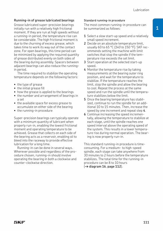
Lubrication
Running-in of grease lubricated bearingsGrease lubricated super-precision bearings initially run with a relatively high frictional moment. If they are run at high speeds without a running-in period, the temperature rise can be considerable. The high frictional moment is due to the churning of excess grease, which takes time to work its way out of the contact zone. For open bearings, this time period can be minimized by applying the required quantity of grease distributed evenly on both sides of the bearing during assembly. Spacers between adjacent bearings can also reduce the running-in period.
The time required to stabilize the operating temperature depends on the following factors:
• the type of grease• the initial grease fill• how the grease is applied to the bearings• the number and arrangement of bearings in
a set• the available space for excess grease to
accumulate on either side of the bearing • the running-in procedure
Super-precision bearings can typically operate with a minimum quantity of lubricant when properly run-in, enabling the lowest frictional moment and operating temperature to be achieved. Grease that collects on each side of the bearing acts as a reservoir, enabling oil to bleed into the raceway to provide effective lubrication for a long time.
Running-in can be done in several ways. Wherever possible and regardless of the pro-cedure chosen, running-in should involve operating the bearing in both a clockwise and counter-clockwise direction.
Standard running-in procedureThe most common running-in procedure can be summarized as follows:
1 Select a slow start-up speed and a relatively small speed increment.
2 Decide on an absolute temperature limit, usually 60 to 65 °C (140 to 150 °F). SKF rec-ommends setting the machine with limit switches that stop the spindle if the tem-perature rise exceeds the set limit.
3 Start operation at the selected start-up speed.
4 Monitor the temperature rise by taking measurements at the bearing outer ring position, and wait for the temperature to stabilize. If the temperature reaches the limit, stop the spindle and allow the bearing to cool. Repeat the process at the same speed and run the spindle until the tempera-ture stabilizes below the limit.
5 Once the bearing temperature has stabil-ized, continue to run the spindle for an add-itional 10 to 15 minutes. Then, increase the speed by one increment and repeat step 4.
6 Continue increasing the speed incremen-tally, allowing the temperature to stabilize at each stage, until the spindle reaches one speed interval above the operating speed of the system. This results in a lower tempera-ture rise during normal operation. The bear-ing is now properly run-in.
This standard running-in procedure is time-consuming. For a medium- to high-speed spindle, each stage can take anywhere from 30 minutes to 2 hours before the temperature stabilizes. The total time for the running-in procedure can be 8 to 10 hours († diagram 16, page 112).
111
1

Principles of bearing selection and application
Short running-in procedureAn alternative to the standard running-in pro-cedure reduces the number of stages and shortens the overall running-in time. The main steps can be summarized as follows:
1 Select a start-up speed approximately 20 to 25% of the attainable speed for grease lubrication († product tables) and choose a relatively large speed increment.
2 Decide on an absolute temperature limit, usually 60 to 65 °C (140 to 150 °F). It is advisable to set the machine with limit switches that stop the spindle if the tem-perature rise exceeds the limits set.
3 Start operation at the chosen start-up speed.
4 Monitor the temperature by taking meas-urements at the bearing outer ring position until the temperature reaches the limit. Care should be taken as the temperature increase may be very rapid.
5 Stop operation and let the outer ring of the bearing cool down by 5 to 10 °C (10 to 20 °F).
6 Start operation at the same speed a second time and monitor the temperature until the limit is reached again.
7 Repeat steps 5 and 6 until the temperature stabilizes for 10 to 15 minutes below the limit. The bearing is run-in at that particu-lar speed.
8 Increase the speed by one increment and repeat steps 4 to 7.
9 Proceed until the bearing is running at one speed increment above the operating speed of the system. This results in a lower temperature rise during normal operation. The bearing is now properly run-in.
Although each stage may have to be repeated several times, each cycle is just a few minutes long. The total time for this running-in proce-dure is substantially less than for the standard procedure.
Diagram 16
Graphic representation of a running-in procedure
60 (140)
20 (70) 0
Temperature [°C (°F)] Speed [r/min]
Absolute temperature limit
10 to 15 minutes forstabilized temperature
Normal operating speed of the system
† Stage 1 † Stage 2 † Stage 3 † Stage 4 † Stage 5 Time [h]
Operating temperatureSpeed
112

Lubrication
Oil lubricationOil lubrication is recommended for many appli-cations, as different supply methods can be adapted to suit different operating conditions and the machine’s design. When selecting the most appropriate oil lubrication method for a bearing arrangement, the following application requirements should be considered:
• required quantity and viscosity of the oil • speed and hydrodynamic frictional losses • permissible bearing temperature
The typical relationship between oil quantity / oil flow rate, frictional losses and bearing tem-perature is shown in diagram 17. The diagram illustrates the conditions in different regions:
• Region AThe oil quantity is insufficient to create a hydrodynamic film between the rolling elem-ents and raceways. Metal-to-metal contact leads to increased friction, high bearing temperatures, wear and surface fatigue.
• Region BA larger quantity of oil is available and a cohesive, load-carrying oil film of sufficient thickness to separate the rolling elements and raceways can be formed. Here, the con-
dition is reached where friction and tem-perature are at a minimum.
• Region CA further increase in oil quantity increases frictional heat due to churning and bearing temperature rises.
• Region DThe oil flow quantity increases such that equilibrium between frictional heat gener-ation at the bearing and heat removal by the oil flow is achieved. Bearing temperature peaks.
• Region EWith increasing oil flow, the rate at which heat is removed exceeds the frictional heat generated by the bearing. Bearing tempera-ture decreases.
Maintaining low operating temperatures at extremely high speeds generally requires either an oil-air lubrication system or a circu-lating oil lubrication system with cooling cap-abilities. With these systems, the operating conditions shown in regions B (oil-air) or E (circulating oil) can be maintained.
Diagram 17
Bearing temperature and frictional losses as a function of oil quantity
EDCBA
Bearing temperature,Frictional loss
Bearing temperature
Oil quantity, oil flow rate
Frictional loss
113
1

Principles of bearing selection and application
Oil lubrication methods
Oil bathThe simplest method of oil lubrication is the oil bath. The oil, which is picked up by the rotating components of the bearing, is distributed within the bearing and then flows back to a sump in the housing. Typically, the oil level should almost reach the centre of the lowest rolling element when the bearing is stationary. Oil bath lubrication is particularly suitable for slow speeds. At high speeds, however, too much oil is supplied to the bearings, increasing friction and causing the operating temperature to rise.
Circulating oilIn general, high-speed operation increases frictional heat, elevates operating tempera-tures and accelerates ageing of the oil. To reduce operating temperatures and avoid fre-quent oil changes, the circulating oil lubrication method is generally preferred († fig. 42). Cir-
culation is usually controlled by a pump. After the oil has passed through the bearing, it gen-erally settles in a tank where it is filtered and cooled before being returned to the bearing. Proper filtering decreases the contamination level and extends bearing service life. In bigger systems with several different bearing sizes, the main volume flow from the pump can be split into several smaller flows. The flow rate in each sub-circuit in the system can be checked by SKF flow monitoring devices.
Guideline values for oil flow rates are listed in table 32. For a more accurate analysis, con-tact the SKF application engineering service.
For information about the SKF CircOil sys-tem and SKF flow monitoring devices, refer to the product information available online at skf.com/lubrication.
Fig. 42
Table 32
Oil flow rate guidelines (valid for single bearings)
Bore diameter Oil flow rated Qover incl. low high
mm l/min
– 50 0,3 150 120 0,8 3,6120 400 1,8 6
114

Lubrication
Oil jet The oil jet lubrication method († fig. 43) is an extension of circulating oil systems. A jet of oil under high pressure is directed at the side of the bearing. The velocity of the oil jet should be sufficiently high (≥ 15 m/s) to penetrate the turbulence surrounding the rotating bearing. Oil jet lubrication is used for very high speed operation, where a sufficient, but not exces-sive, amount of oil should be supplied to the bearing without increasing the operating tem-perature unnecessarily.
Oil dropWith the oil drop method, an accurately metered quantity of oil is supplied to the bear-ing at given intervals. The delivered quantity may be relatively small, keeping frictional losses at high speeds to a minimum. However, it is difficult to ascertain whether the oil is able to penetrate the bearing at high speeds and, therefore, individual testing is always recom-mended. Whenever possible, the oil-air method should be preferred over the oil drop method.
Oil mistModern application specific oil mist systems, such as those offered by SKF, matched with a suitable non-toxic and non-carcinogenic oil formulated for minimum stray mist emissions and suitable sealing systems, address environ-mental and health concerns. These systems, when well maintained, provide a cost-effective, environmentally clean way to continuously and effectively atomise oil and deliver metered minimum required quantities to the bearings. Modern oil mist systems suspend oil droplets 1 to 5 µm in size in dry instrument air. The oil to air ratio, which is typically 1:200 000, cre-ates a very lean but effective mixture that is delivered under 0,005 MPa pressure.
Fig. 43
115
1
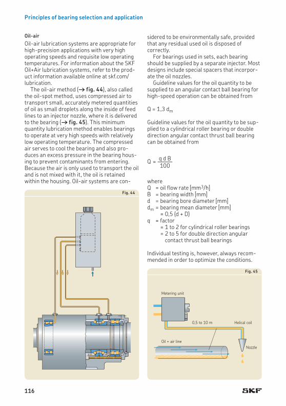
Principles of bearing selection and application
Oil-airOil-air lubrication systems are appropriate for high-precision applications with very high operating speeds and requisite low operating temperatures. For information about the SKF Oil+Air lubrication systems, refer to the prod-uct information available online at skf.com/lubrication.
The oil-air method († fig. 44), also called the oil-spot method, uses compressed air to transport small, accurately metered quantities of oil as small droplets along the inside of feed lines to an injector nozzle, where it is delivered to the bearing († fig. 45). This minimum quantity lubrication method enables bearings to operate at very high speeds with relatively low operating temperature. The compressed air serves to cool the bearing and also pro-duces an excess pressure in the bearing hous-ing to prevent contaminants from entering. Because the air is only used to transport the oil and is not mixed with it, the oil is retained within the housing. Oil-air systems are con-
sidered to be environmentally safe, provided that any residual used oil is disposed of correctly.
For bearings used in sets, each bearing should be supplied by a separate injector. Most designs include special spacers that incorpor-ate the oil nozzles.
Guideline values for the oil quantity to be supplied to an angular contact ball bearing for high-speed operation can be obtained from
Q = 1,3 dm
Guideline values for the oil quantity to be sup-plied to a cylindrical roller bearing or double direction angular contact thrust ball bearing can be obtained from
q d B Q = ——– 100
whereQ = oil flow rate [mm3/h]B = bearing width [mm]d = bearing bore diameter [mm]dm = bearing mean diameter [mm]
= 0,5 (d + D)q = factor
= 1 to 2 for cylindrical roller bearings = 2 to 5 for double direction angular
contact thrust ball bearings
Individual testing is, however, always recom-mended in order to optimize the conditions.
Fig. 44
Metering unit
Oil + air lineNozzle
0,5 to 10 m Helical coil
Fig. 45
116

Lubrication
Different bearing designs show varying sen-sitivity to oil quantity changes. For example, roller bearings are very sensitive, whereas for ball bearings, the quantity can be changed substantially without any major rise in bearing temperature.
A factor influencing temperature rise and reliability of oil-air lubrication is the lubrication interval, i.e. the time in between two measures from the oil-air lubricator. Generally, the lubri-cation interval is determined by the oil flow rate generated by each injector and the oil quantity supplied per hour. The interval can vary from one minute to one hour, with the most common interval being 15 to 20 minutes.
Feed lines from the lubricator are 1 to 5 m in length, depending on the lubrication interval. A filter that prevents particles > 5 µm from reaching the bearings should be incorporated. The air pressure should be 0,2 to 0,3 MPa, but should be increased for longer runs to com-pensate for the pressure drop along the pipe’s length.
To maintain the lowest possible operating temperature, ducts must be able to drain any excess oil away from the bearing. With hori-zontal shafts it is relatively easy to arrange drainage ducts on each side of the bearings. For vertical shafts the oil passing the upper bearing(s) should be prevented from reaching the lower bearings, which would otherwise receive too much lubricant. Drainage, together with a sealing device, should be incorporated beneath each bearing. An effective seal should also be located at the spindle nose to prevent lubricant from reaching the work piece.
The oil nozzles should be positioned so that oil can be introduced into the contact area between the rolling elements and raceways without interference by the cage. For the diameter (measured on the bearing) where oil injection should take place, refer to tables 33 and 34 († pages 118 and 119). For bear-ings equipped with alternative cages that are not listed, contact the SKF application engin-eering service.
The attainable speeds listed in the product tables for oil lubrication refer specifically to oil-air lubrication.
117
1

Principles of bearing selection and application
Table 33
Oil nozzle position for angular contact ball bearings
Bore diameter
Size Oil nozzle position dn for bearings in the series718 CD 719 CD 719 CE 719 CB 70 CD 70 CE 70 CB 72 CD
d 718 ACD 719 ACD 719 ACE 719 ACB 70 ACD 70 ACE 70 ACB 72 ACD
mm – mm
6 6 – – – – 10,3 10,1 – –7 7 – – – – 11,7 11,4 – 13,68 8 – – 12,2 – 13,6 13,3 – 14,39 9 – – 13,3 – 15,1 14,8 – 16,3
10 00 13,4 14,8 14,8 – 16 16,5 – 18,312 01 15,4 16,8 16,8 – 18 18,5 – 2015 02 18,4 20,1 20 – 21,5 21,9 – 2317 03 20,4 22,1 22 – 23,7 24,1 – 25,9
20 04 24,5 26,8 26,7 – 28,4 28,1 – 31,125 05 29,5 31,8 31,8 – 33,4 33,1 – 36,130 06 34,5 36,8 36,8 36,6 39,3 39,9 40 42,735 07 39,5 43 43 43 45,3 45,6 46,1 49,7
40 08 44,5 48,7 48 49,1 50,8 51,6 51,6 56,245 09 50 54,2 54,2 54,2 56,2 57,6 57,2 60,650 10 55,6 58,7 58,4 58,7 61,2 62,3 61,8 65,655 11 61,3 64,7 64,6 64,8 68,1 69,6 69,2 72,6
60 12 66,4 69,7 69,6 69,8 73,1 74,6 74,2 80,165 13 72,4 74,7 74,5 74,8 78,1 79,3 79 86,670 14 77,4 81,7 81,5 81,9 85 86,5 86,1 91,675 15 82,4 86,7 86,5 86,9 90 91,5 91,1 96,6
80 16 87,4 91,7 91,5 91,7 96,9 98,5 98 103,485 17 94,1 98,6 98,6 99,2 101,9 103,5 103 111,590 18 99,1 103,3 103,5 103,9 108,7 111 110 117,595 19 104,1 108,6 108,5 109 113,7 115,4 115 124,4
100 20 109,1 115,6 115,4 116,1 118,7 120,4 120 131,4105 21 114,6 120,6 – – 125,6 – – 138,4110 22 120,9 125,6 125,4 125,7 132,6 135,4 134,6 145,9120 24 130,9 137,6 137,4 138,2 142,6 144,9 144,7 158,2
130 26 144 149,5 – – 156,4 – – 170,7140 28 153,2 159,5 – – 166,3 – – 184,8150 30 165,6 173,5 – – 178,2 – – –160 32 175,6 183,5 – – 191,4 – – –
170 34 – 193,5 – – 205,8 – – –180 36 – 207,4 – – 219,7 – – –190 38 – 217,4 – – 229,7 – – –200 40 – 231,4 – – 243,2 – – –
220 44 – 251,4 – – 267,1 – – –240 48 – 271,4 – – 287 – – –260 52 – 299,7 – – 315 – – –280 56 – 319,7 – – – – – –
300 60 – 347 – – – – – –320 64 – 367 – – – – – –340 68 – 387 – – – – – –360 72 – 407 – – – – – –
dnd
118

Lubrication
Table 34
Oil nozzle position for cylindrical roller and double direction angular contact thrust ball bearings
Bore diameter
Size Oil nozzle position dn for bearings in the series1)
N 10 N 10 PHA NNU 49 BTMd NN 30
mm – mm
25 05 40,5 – – –30 06 47,6 – – –35 07 54 – – –
40 08 60 52,1 – –45 09 66,4 57,9 – –50 10 71,4 63 – –
55 11 79,8 70,1 – –60 12 85 75,2 – 73,865 13 89,7 80,1 – 78,8
70 14 98,5 87,7 – 86,175 15 103,5 92,7 – 91,180 16 111,4 99,3 – 97,9
85 17 116,5 – – 102,990 18 125,4 – – 109,795 19 130,3 – – 114,7
100 20 135,3 – 113,8 119,7105 21 144,1 – 119 –110 22 153 – 124 134,1
120 24 162,9 – 136,8 144,1130 26 179,6 – 147 158,3140 28 188 – 157 168,3
150 30 201,7 – 169,9 179,9160 32 214,4 – 179,8 191,6170 34 230,8 – 189,8 205,4
180 36 248,9 – 203,5 219,9190 38 258,9 – 213 –200 40 275,3 – 227 –
220 44 302,4 – 247 –240 48 322,4 – 267 –260 52 355,2 – 294,5 –
280 56 375,3 – 313,5 –
The illustrations show examples only. Position depends on design and series.1) For bearings in the N 10 series equipped with an TNHA cage, bearings in the NN 30 and NNU 49 series with d > 280 mm, contact
the SKF application engineering service.
dnd dnd dnd
119
1

Principles of bearing selection and application
Direct oil-air lubricationFor super-precision angular contact ball bear-ings operating at very high speeds, the injec-tion of small amounts of oil-air directly through the outer ring is beneficial. With this method, lubricant dispersion is prevented, as the lubri-cant is supplied directly and safely to the ball/raceway contact area. As a result, lubricant consumption is minimized and bearing per-formance is improved. The different variants († fig. 45) for direct oil-air lubrication provide different benefits:
• Bearings with an annular groove and O-rings in the outer ring (designation suffix L or L1) prevent lubricant leakage between the bearing and its seat in the housing. For bearings without these features (designation suffix H or H1), SKF recommends machining the housing bore and incorporating O-rings into the bearing arrangement design.
• Bearings with lubrication holes on the thick side of the bearing shoulder (designation suffix H1 or L1) enable the lubricant to be supplied very close to the ball/raceway con-tact area. The locations of these lubrication holes enable the bearings to achieve max-imum speeds.
H H1 L L1
Fig. 45
120

Lubrication
Direct minimum quantity lubrication with minimal air consumptionThe use of a continuous air flow in an oil-air lubrication system includes some system-related disadvantages like the high cost of compressed air, high noise levels and a com-plex dosing and control process. The SKF Microdosage system († fig. 46) virtually elim-inates these disadvantages and offers better control and a lower cost of ownership.
Designed for ultra high speed spindles where the speed factor A ≥ 2 000 000 mm/min, this system delivers precisely metered amounts of oil to each bearing based on the machine tool’s CAM program. The SKF Microdosage system also automatically re-calibrates when condi-tions like temperature or oil viscosity change. With this technology, oil consumption can typ-ically be reduced to 0,5 to 5 mm3/min with a minimal amount of compressed air.
For information about the SKF Microdosage system, refer to the product information avail-able online at skf.com/lubrication.
Lubricating oilsTo lubricate super-precision bearings, high-quality lubricating oils without EP additives are generally recommended. The requisite viscos-ity of the oil can be determined following the recommendations under Lubrication conditions – the viscosity ratio k in the SKF catalogue Rolling bearings or at skf.com, and is essentially a function of bearing size, speed and operating temperature.
Calculations can be made using the SKF pro-gram, Viscosity, available online at skf.com/bearingcalculator.
With oil-air lubrication systems, many oil types are suitable. Oils with a viscosity of 40 to 100 mm2/s at 40 °C (105 °F) are typically used as are oils with EP additives which are prefer-able, especially for roller bearings. Oils with a viscosity of 10 to 15 mm2/s at 40 °C (105 °F) are typically used for oil jet lubrication, whereas oil mist lubrication systems typically use oils with a viscosity of 32 mm2/s at 40 °C (105 °F).
The intervals at which the oil should be changed when using an oil bath, circulating oil or oil jet lubrication system, depend mainly on the operating conditions and the quantity of oil involved. When oil drop, oil mist or oil-air lubri-cation systems are used, the lubricant is sup-plied to the bearings only once.
OilElectrical signal
Fig. 46
121
1

Principles of bearing selection and application
Oil cleanliness Oil cleanliness, which affects bearing service life and performance, requires an effective sealing system. Even with effective seals, how-ever, the condition of the oil should be moni-tored on a regular basis. This is particularly true for oil re-circulation systems where the ingress of coolants, cutting oils, and other liquid contaminants can alter the lubricating properties of the oil.
Oil cleanliness requirements can be described by the number of particles per millilitre of oil for different particle sizes. ISO 4406 provides a coding system for the level of solid contaminants. The oil cleanliness requirements for high-precision applications like electro-spindles go beyond this coding. The maximum particle size should not exceed 5 µm. The acceptable contamination levels can be specified as an extrapolation of the contam-ination codes to ISO 4406 († diagram 18):
• 10/7, for new spindles • 13/10, after long use (~ 2 000 hours)
Lubricant storageThe conditions under which lubricants are stored can have an adverse effect on their per-formance. Inventory control can also play an important role. Therefore, SKF recommends a “first in, first out” inventory policy.
Lubricant properties may vary considerably during storage due to exposure to air/oxygen, temperature, light, water, moisture and other contaminants, or oil separation. Therefore, lubricants should be stored in a cool, dry, indoor area and should never be exposed to direct sunlight. The lubricants should be stored in their original containers, which should be kept closed until needed. After use, the con-tainers should be resealed immediately.
The recommended maximum storage time is two years for greases and ten years for lubricating oils; assuming reasonable stock keeping practices and protection from exces-sive heat and cold.
Grease or oil that has exceeded the recom-mended shelf life is not necessarily unsuitable for service. However, it is advisable to confirm that the lubricant still meets the product requirements and specifications.
Diagram 18
Acceptable oil contamination levels
103
102
10
1
10–1
10–2
17
16
15
14
13
12
11
10
9
8
7
6
5
4
3
2
1
1,3
6,4
3,2
1,6
8
4
2
5
2,5
1,3
6,4
3,2
1,6
8
4
2
5 1510
10/7
13/10
Number of particles per millilitreof oil larger than indicated size
Particle size [mm]
Scale number
122

Mounting and dismounting
Mounting and dismountingWhen mounting or dismounting super-preci-sion bearings, all recommendations and guide-lines valid for rolling bearings should be con-sidered. For recommendations and guidelines, refer to Mounting, dismounting and bearing care in the SKF catalogue Rolling bearings or at skf.com and to the SKF bearing maintenance handbook (ISBN 978-91-978966-4-1). For mounting and dismounting instructions for individual bearings, visit skf.com/mount.
Where to mountBearings should be mounted in a dry, dust-free area away from machines producing swarf and dust. When bearings have to be mounted in an unprotected area, steps should be taken to protect the bearing and mounting position from contaminants like dust, dirt and mois-ture. This can be done by covering or wrapping the bearings and machine components with plastic or foil.
Methods and toolsSuper-precision bearings are reliable machine elements that can provide long service life, provided they are mounted and maintained properly. Proper mounting requires experi-ence, accuracy, a clean work environment and the appropriate tools.
To promote proper mounting techniques, speed, accuracy and safety, SKF offers a com-prehensive assortment of high-quality mount-ing and maintenance products. The assort-ment includes everything from mechanical and hydraulic tools to bearing heaters and grease. Detailed information about maintenance prod-ucts is available online at skf.com.
To be sure that bearings are mounted and maintained properly, SKF offers seminars and hands-on training courses as part of the SKF Reliability Systems concept. Installation and maintenance assistance may also be available from your local SKF company or SKF Author-ized Distributor.
Mounting recommendationsCompared to other rolling bearings, mounting super-precision bearings requires more ac-curacy, more caution and more advanced skills.
Mounting bearings with thin-walled ringsSuper-precision bearings often have rings that are thin relative to their size. For these bear-ings, only limited mounting forces should be applied. Therefore, SKF recommends using hot mounting methods for all super-precision bearings with thin-walled rings. For bearings in the NNU 49 series with a tapered bore, SKF recommends using the oil injection method.
Hot mountingSuper-precision bearings are typically mounted with a low degree of interference. That means a relatively small difference in temperature between the bearing ring and its mating components is required. The following temperature differences are often sufficient:
• 20 to 30 °C (35 to 55 °F) between the inner ring and shaft
• 10 to 30 °C (20 to 55 °F) between the hous-ing bore and outer ring
To heat bearings evenly and reliably, SKF rec-ommends using SKF electric induction heaters († fig. 47).
Stepped sleeves are sometimes used to locate bearings on a shaft and are therefore installed with a tight interference fit. Because of this, stepped sleeves require a greater dif-
Fig. 47
123
1

Principles of bearing selection and application
ference in temperature between mating com-ponents during installation. Temperature dif-ferences for installation are listed for:
• stepped sleeves without O-rings († table 16, page 82)
• stepped sleeves with O-rings († table 17, page 83)
Test runningOnce assembly is complete, an application should undergo a test run to determine that all components are operating properly. During a test run, the bearing(s) should run under par-tial load and, where there is a wide speed range, at slow or moderate speeds. A rolling bearing should never be started up unloaded and then accelerated to high speed, as there is a significant risk that the rolling elements will slide and damage the raceways, or that the cage will be subjected to impermissible stresses.
Any noise or vibration can be checked using an SKF electronic stethoscope. Normally, bearings produce an even “purring” noise. Whistling or screeching indicates inadequate lubrication. An uneven rumbling or hammering is in most cases due to the presence of con-taminants in the bearing or to bearing damage caused during mounting.
An increase in bearing temperature immedi-ately after start-up is normal. In the case of grease lubrication, the temperature does not drop until the grease has been evenly distrib-uted in the bearing arrangement, after which an equilibrium temperature is reached. For additional information about running-in of grease lubricated bearings, refer to Runningin of grease lubricated bearings († page 111).
Unusually high temperatures or constant peaking indicate that the preload is too heavy, that there is too much lubricant in the ar range-ment or that the bearing is radially or axially distorted. Other causes could be that associ-ated components have not been made or mounted correctly, or that the seals are gener-ating too much heat.
During the test run, or immediately after-wards, check the seals, any lubrication systems and all fluid levels. If noise and vibration levels are severe, it is advisable to check the lubricant for signs of contamination.
DismountingBecause the degree of the interference fit is relatively low for super-precision bearings, lower ring dismounting forces are needed compared to other rolling bearings.
Dismounting forcesFor bearings in spindle applications, the dis-mounting forces can be estimated as follows:
• dismounting a set of three angular contact ball bearings from the housing † F ~ 0,02 D
• dismounting a set of three angular contact ball bearings from the shaft † F ~ 0,07 d
• dismounting a cylindrical roller bearing from its tapered seat † F ~ 0,3 d
where F = dismounting force [kN] D = bearing outside diameter [mm] d = bearing bore diameter [mm]
Reusing bearingsTo determine if a bearing can be reused, it must be inspected carefully. A detailed inspec-tion requires disassembling the bearing. Angu-lar contact ball bearings cannot be disassem-bled without damage unless special tools are used. Cylindrical roller bearings can only be partly disassembled.
SKF does not recommend reusing super-precision bearings. In most cases, the risk for unplanned downtime or unsatisfactory per-formance outweighs the cost of new bearings.
Bearings should be dismounted carefully, regardless of whether they will be reused, because careless dismounting could damage associated components. Also, if the bearing is dismounted carefully, it can then be used for condition and damage analysis if required.
124

Bearing storage
SKF spindle serviceMachine tool spindles often require special tools and skills for maintenance and repair. SKF supports customers with a worldwide network of SKF Spindle Service Centres († skf.com). The services offered include spindle reconditioning, from bearing replace-ment to shaft and nose restorations, perform-ance upgrades and analysis. SKF can also pro-vide complete monitoring services as well as preventative maintenance services for machine tool spindles.
Bearing storageThe conditions under which bearings and seals are stored can have an adverse effect on their performance. Inventory control can also play an important role in performance, particularly if seals are involved. Therefore, SKF recom-mends a “first in, first out” inventory policy.
Storage conditionsTo maximize the service life of bearings, SKF recommends the following basic housekeeping practices:
• Store bearings flat, in a vibration-free, dry area with a cool, steady temperature.
• Control and limit the relative humidity of the storage area as follows: – 75% at 20 °C (68 °F) – 60% at 22 °C (72 °F) – 50% at 25 °C (77 °F)
• Keep bearings in their original unopened packages until immediately prior to mount-ing to prevent the ingress of contaminants and corrosion.
• Bearings that are not stored in their original packaging should be well protected against corrosion and contaminants.
Shelf life of open bearingsSKF bearings are coated with a rust-inhibiting compound and suitably packaged before distri-bution. For open bearings, the preservative provides protection against corrosion for approximately three years, provided the stor-age conditions are appropriate.
Shelf life of sealed bearingsThe maximum storage interval for sealed SKF bearings is dictated by the lubricant inside the bearings. Lubricant deteriorates over time as a result of ageing, condensation, and separation of the oil and thickener. Therefore, sealed bearings should not be stored for more than three years.
125
1


Product table2.1 Angular contact ball bearings . . . . . 198
Assortment . . . . . . . . . . . . . . . . . . . . . . 128
Designs and variants . . . . . . . . . . . . . . . 128Bearing series . . . . . . . . . . . . . . . . . . . . . 130Contact angles . . . . . . . . . . . . . . . . . . . . . 130High-capacity D design bearings . . . . . . 131High-speed E design bearings . . . . . . . . 132High-speed B design bearings . . . . . . . . 132Hybrid bearings . . . . . . . . . . . . . . . . . . . . 133Cages . . . . . . . . . . . . . . . . . . . . . . . . . . . . 134Sealing solutions . . . . . . . . . . . . . . . . . . . 136Direct oil-air lubrication . . . . . . . . . . . . . 136Bearings made of NitroMax steel . . . . . . 141
Bearing arrangement design . . . . . . . . 141Single bearings and bearing sets . . . . . . 141
Single bearings . . . . . . . . . . . . . . . . . . 141Bearing sets . . . . . . . . . . . . . . . . . . . . 142
Bearing arrangements . . . . . . . . . . . . . . 142
Markings on bearings and bearing sets . . . . . . . . . . . . . . . . . . . . . . . . . . . . . 145
Bearing data . . . . . . . . . . . . . . . . . . . . . 146(Boundary dimensions, chamfer dimensions, tolerances)
Preload . . . . . . . . . . . . . . . . . . . . . . . . . . 151Bearings manufactured pre-set for preload . . . . . . . . . . . . . . . . . . . . . . . . . . 151Preload in mounted bearing sets . . . . . . 162Preload with a constant force . . . . . . . . . 165Preload by axial displacement . . . . . . . . . 166Individual adjustment of preload . . . . . . . 166
Spacer rings . . . . . . . . . . . . . . . . . . . . 167Effect of rotational speed on preload . . . 167
Axial stiffness . . . . . . . . . . . . . . . . . . . . 173
Fitting and clamping bearing rings . . . 183Calculating the required tightening torque . . . . . . . . . . . . . . . . . . . . . . . . . . . 184
Locking procedure . . . . . . . . . . . . . . . . 185
Load carrying capacity of bearing sets . . . . . . . . . . . . . . . . . . . . . . . . . . . . . 189
Equivalent bearing loads . . . . . . . . . . . 190Equivalent dynamic bearing load . . . . . . 190Equivalent static bearing load . . . . . . . . . 191
Attainable speeds . . . . . . . . . . . . . . . . . 192
Mounting . . . . . . . . . . . . . . . . . . . . . . . . 194Pressing bearing sets together during hot mounting . . . . . . . . . . . . . . . . . . . . . . 194Package markings . . . . . . . . . . . . . . . . . . 194
Designation system . . . . . . . . . . . . . . . . 196
More informationBearing life and load ratings . . . . . . . . 33Requisite minimum load . . . . . . . . . . . 34Chamfer dimension limits . . . . . . . . . . 47Materials . . . . . . . . . . . . . . . . . . . . . . . 51Design considerations . . . . . . . . . . . . . 57Lubrication . . . . . . . . . . . . . . . . . . . . . 99Mounting and dismounting . . . . . . . . . 123Bearing storage . . . . . . . . . . . . . . . . . . 125
Angular contact ball bearings
127
2

Angular contact ball bearings
AssortmentSKF manufactures super-precision angular contact ball bearings for shaft diameters from 6 to 360 mm. Application requirements vary, and as a result, the SKF assortment of super-precision angular contact ball bearings includes four ISO dimension series, in numer-ous executions. The wide selection of designs and variants enables them to be incorporated into virtually every machine tool application as well as other applications where precision bearings are required.
SKF can supply super-precision angular contact ball bearings with a variety of design features:
• three different contact angles• three different ball sizes – D design, E design
and B design• two different ball materials (hybrid variant)• sealing solutions• direct oil-air lubrication features• two different ring materials (NitroMax steel
variant)
The assortment of super-precision angular contact ball bearings is shown in table 1.
Designs and variantsSingle row SKF super-precision angular con-tact ball bearings († fig. 1) are non-separable and, like all angular contact ball bearings, have raceways in the inner and outer rings that are displaced relative to each other in the direction of the bearing axis. This means that in addition to radial loads, these bearings can also accom-modate axial loads in one direction. Radial loads induce axial forces in these bearings that need to be balanced by counterforces. An angular contact ball bearing is, therefore, always adjusted against a second bearing or used in sets.
The ring shoulders can have a different height on one or both bearing rings. Every bearing has the largest possible number of balls, which are guided by a window-type cage.
Fig. 1
128
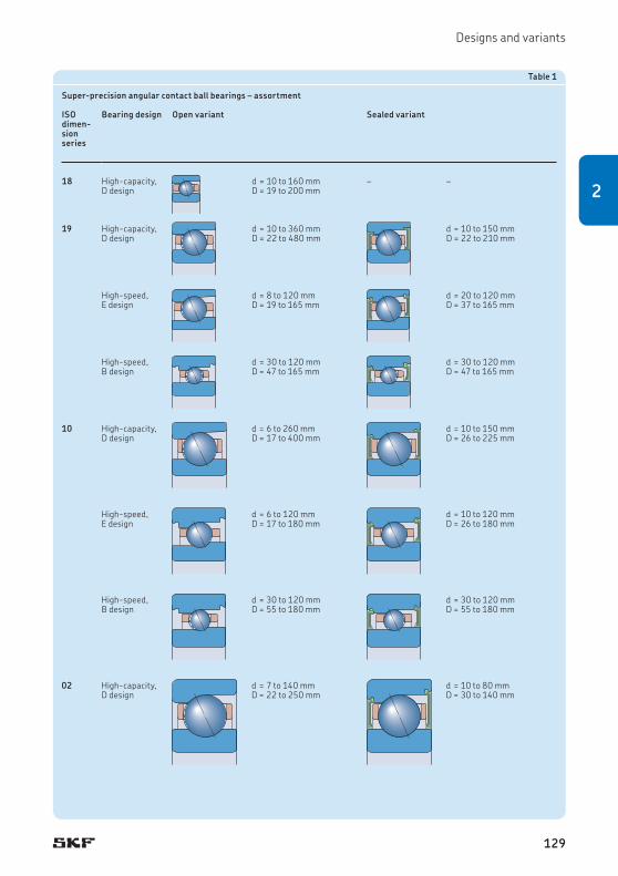
Designs and variants
Table 1
Super-precision angular contact ball bearings – assortment
ISO dimen-sion series
Bearing design Open variant Sealed variant
18 High-capacity, D design
d = 10 to 160 mmD = 19 to 200 mm
– –
19 High-capacity, D design
d = 10 to 360 mmD = 22 to 480 mm
d = 10 to 150 mmD = 22 to 210 mm
High-speed, E design
d = 8 to 120 mmD = 19 to 165 mm
d = 20 to 120 mmD = 37 to 165 mm
High-speed, B design
d = 30 to 120 mmD = 47 to 165 mm
d = 30 to 120 mmD = 47 to 165 mm
10 High-capacity, D design
d = 6 to 260 mmD = 17 to 400 mm
d = 10 to 150 mmD = 26 to 225 mm
High-speed, E design
d = 6 to 120 mmD = 17 to 180 mm
d = 10 to 120 mmD = 26 to 180 mm
High-speed, B design
d = 30 to 120 mmD = 55 to 180 mm
d = 30 to 120 mmD = 55 to 180 mm
02 High-capacity, D design
d = 7 to 140 mmD = 22 to 250 mm
d = 10 to 80 mmD = 30 to 140 mm
129
2

Angular contact ball bearings
Bearing seriesThe SKF assortment of super-precision angu-lar contact ball bearings includes bearings in the following dimension series:
• ultra light 718 series• extremely light 719 series• light 70 series• robust 72 series
The cross-sections of the four bearing series are compared in fig. 2 for the same bore and same outside diameters. Each bearing series has characteristic features that make it par-ticularly suitable for certain bearing applications.
Where a low cross section is a critical design parameter, bearings in the 718 series should be selected. If more radial space is available, and loads are not very heavy, bearings in the 719 or 70 series could be used. Bearings in the 72 series have the largest cross section for a given bore diameter and are suitable for heavy loads at relatively slow speeds.
If a high degree of stiffness is required, bearings in the 718 and 719 series are typ ic-al ly used. Bearings in these two series contain the largest number of balls, relative to the selected bore size, and can also accommodate
the largest shaft diameter, relative to their outside diameter. Both characteristics are par-ticularly important for system rigidity, as the rigidity of a spindle increases with its shaft diameter, and the rigidity of a bearing arrange-ment increases with the number of balls.
Contact anglesSuper-precision angular contact ball bearings are manufactured with the following contact angles († fig. 3):
• a 15° contact angle, designation suffix C• a 25° contact angle, designation suffix AC
For some series, bearings with an 18° contact angle, designation suffix F, are available on request.
A larger contact angle provides a higher degree of axial stiffness and a higher axial load carrying capacity. However, speed capability, radial stiffness, and radial load carrying cap-acity are reduced.
719718
7072
72719718 70
Fig. 2
130

Designs and variants
15° 18° 25°
Fig. 3 Fig. 4
High-capacity D design bearingsD design bearings († fig. 4) are designed to accommodate heavy loads at relatively high speeds under low to moderate operating tem-peratures. When compared to other precision angular contact ball bearings, D design bear-ings contain the maximum number and size of balls. Their close osculation provides a rela-tively high degree of stiffness and the highest possible load carrying capacity.
ApplicationsTypical applications for bearings in the 718 .. D series include:
• machine tools, e.g. multispindle drilling heads († fig. 14, page 60)
• robotics• printing• measuring systems• racing car wheels
Typical applications for bearings in the 719 .. D and 70 .. D series include:
• machining centres (horizontal and vertical) († fig. 17, page 63)
• milling machines• lathes († fig. 11, page 58)• external and surface grinding machines• boring machines• machines for cutting or polishing stones and
glass• semiconductor industry, e.g. units for
detecting defects on silicon wafer chips († fig. 15, page 61)
• boat gyrostabilizers• telescopes• microturbines• racing/super car wheels• medical equipment
Typical applications for bearings in the 72 .. D series include:
• machine tool spindles, e.g. live centre spin-dles († fig. 13, page 59)
• lathes (main spindles, tailstock)• grinding machines• boring machines• Parallel Kinematic Machines (PKM)• dynamometers for engine testing• high-speed turbochargers
131
2

Angular contact ball bearings
High-speed E design bearingsE design bearings († fig. 5), when compared to D design bearings, have a more open os cul-ation and a maximum number of smaller balls. They can therefore accommodate very high speeds but do not have the same high load carry ing capacity as D design bearings. Com-pared to B design bearings, E design bearings have a slightly higher speed capability and can accommodate heavier loads.
ApplicationsTypical applications for bearings in the 719 .. E and 70 .. E series include:
• electro-spindles († fig. 16, page 62)• high-speed machining centres (horizontal
and vertical) († fig. 17, page 63)• high-speed milling machines• high-speed internal grinding machines
(† fig. 19, page 64)• high-speed spindles for PCB drilling• woodworking machines
High-speed B design bearingsB design bearings († fig. 6) are designed for high-speed operation and are best suited for lighter loads and lower operating tempera-tures. When compared to E and D design bear-ings, B design bearings are equipped with the maximum number of very small balls. The smaller, lighter balls reduce the centrifugal loads acting on the outer ring raceway and therefore reduce the stresses on the rolling contact surfaces. As smaller balls require less space, the bearing rings have a larger cross section, making them less susceptible to dis-tortion resulting from irregularities of the bearing seat, either on the shaft or in the housing.
ApplicationsTypical applications for bearings in the 719 .. B and 70 .. B series include:
• electro-spindles († fig. 18, page 63)• metal cutting machines († fig. 18)• woodworking machines• milling machines• machining centres
Fig. 5 Fig. 6
132

Designs and variants
Hybrid bearingsHybrid angular contact ball bearings (designa-tion suffix HC) have rings made of bearing steel and rolling elements made of bearing grade silicon nitride (ceramic). As ceramic balls are lighter and have a higher modulus of elasticity and lower coefficient of thermal expansion than steel balls, hybrid bearings can provide the following advantages:
• higher degree of rigidity• higher speed capability • reduced centrifugal and inertial forces
within the bearing• minimized stress at the outer ring rolling
contacts at high speeds• reduced frictional heat• less energy consumption• extended bearing and grease service life• less prone to skid smearing damage and
cage damage when subject to frequent rapid starts and stops
• less sensitive to temperature differences within the bearing
• more accurate preload/clearance control
For additional information about silicon nitride, refer to Materials for bearing rings and rolling elements († page 51).
133
2

Angular contact ball bearings
CagesDepending on their series and size, single row super-precision angular contact ball bearings are fitted as standard with one of the following cages († matrix 1):
• a cotton fabric reinforced phenolic resin cage, window-type, outer ring centred, no designation suffix († fig. 7)
• a glass fibre reinforced PEEK cage, window-type, outer ring centred, designation suffix TNHA († fig. 8)
• a carbon fibre reinforced PEEK cage, win-dow-type, outer ring centred, no designa-tion suffix († fig. 9)
• a machined brass cage, window-type, outer ring centred, designation suffix MA
The lightweight polymer cages reduce inertial and centrifugal forces while maximizing the effectiveness of the lubricant.
Other cage materials and designs are avail-able on request. Contact the SKF application engineering service.
For additional information about materials, refer to Cage materials († page 55).
Fig. 7
Fig. 8
Fig. 9
134

Designs and variants
67891012151720253035404550556065707580859095100105110120130140150160170180190200220240260280300320340360
678900010203040506070809101112131415161718192021222426283032343638404448525660646872
718
.. D
719
.. D
70 ..
D
719
.. E
70 ..
E
719
.. B
70 ..
B
72 ..
D
Bor
e di
amet
er [m
m]
Size
Cage materialsfor bearings in the series
Cotton fabric reinforced phenolic resin
Glass fibre reinforced PEEK
Carbon fibre reinforced PEEK
Machined brass
Matrix 1
135
2

Angular contact ball bearings
Sealing solutionsThe most common bearings can be supplied with an integral seal fitted on both sides (des-ignation prefix S). The seal forms an extremely narrow gap with the inner ring shoulder († fig. 10), and therefore speed capability is not compromised.
The seals are made standard of an oil- and wear-resistant NBR and are reinforced with sheet steel. On request, bearings can be sup-plied with seals made of FKM. For additional information, refer to Seal materials († page 56).
Sealed bearings are filled as standard with a high-quality, low-viscosity grease that has a lithium soap thickener and a synthetic ester base oil. The quantity of grease fills ~ 15% of the free space in the bearing. The temperature range for the grease is –55 to + 110 °C (–65 to +230 °F). On request, the bearings can be supplied with other greases.
For additional information, contact the SKF application engineering service.
When compared to bearing arrangements with open bearings and external seals, sealed bearings can provide a number of advantages, including:
• potential for extended bearing service life• extended maintenance intervals• reduced inventory• reduced risk of lubricant contamination dur-
ing mounting and operation
D design E design B design
Fig. 10
Sealed bearings are lubricated for life. They should not be washed or heated to tempera-tures above 80 °C (175 °F). If a sealed bearing is to be heated for mounting, an induction heater must be used and the bearing should be fitted immediately to minimize the time that the bearing is exposed to high temperatures. For information about the storage interval of sealed bearings, refer to Shelf life of sealed bearings († page 125).
Direct oil-air lubricationSome very high speed applications require open bearings in the 719 .. D and 70 .. D series, 719 .. E and 70 .. E series, and 719 .. B and 70 .. B series to be lubricated with minimal amounts of oil, directly through their outer rings.
On request, bearings can be supplied with two lubrication holes in their outer rings. Bear-ings with an annular groove or an annular groove and two annular O-ring grooves, com-plete with O-rings to seal to the bearing hous-ing bore, are also available. The positions of these features are listed in the following tables:
• table 2 for bearings in the 719 .. D and 70 .. D series
• table 3 († page 138) for bearings in the 719 .. E and 70 .. E series
• table 4 († page 140) for bearings in the 719 .. B and 70 .. B series
136

Designs and variants
Table 2
Dimensions for direct oil-air lubrication – 719 .. D and 70 .. D bearing series
Bore diam-eter
Size DimensionsVariants for bearings in the 719 .. D series Variants for bearings in the 70 .. D seriesH1 L H H1 L
d C1 K C1 C2 C3 b C1 K C1 K C1 C2 C3 b
mm – mm
6 6 – – – – – – 3,65 0,5 – – – – – –7 7 – – – – – – 3,65 0,5 – – – – – –8 8 – – – – – – 4,25 0,5 – – – – – –9 9 – – – – – – 4,25 0,5 – – – – – –10 00 – – – – – – 4,75 0,5 – – – – – –
12 01 – – – – – – 4,9 0,5 – – – – – –15 02 – – – – – – 5,35 0,5 – – – – – –17 03 – – – – – – 6,05 0,5 – – – – – –20 04 – – – – – – 7,15 0,5 – – – – – –25 05 – – – – – – 7,25 0,5 – – – – – –
30 06 – – – – – – 7,8 0,5 – – – – – –35 07 – – – – – – 8,4 0,5 – – – – – –40 08 – – – – – – 8,95 0,5 – – – – – –45 09 – – – – – – 9,45 0,5 – – – – – –50 10 – – – – – – 9,6 0,5 – – – – – –
55 11 – – 6,5 3,2 2 2,2 – – 4,88 0,5 9 4,3 3,8 2,460 12 – – 6,5 3,2 2 2,2 – – 4,88 0,5 9 4,3 3,8 2,665 13 – – 6,5 3,2 2 2,2 – – 4,9 0,5 9,7 4,3 3,8 1,970 14 4,46 0,5 8,6 3,5 2,8 2 – – 5,39 0,5 10,9 4,4 3,9 1,775 15 4,46 0,5 8,6 3,5 2,8 2 – – 5,4 0,5 10,9 3,9 3,4 1,8
80 16 4,46 0,5 8,6 3,5 2,8 2 – – 5,89 0,5 11,1 4,4 3,8 2,885 17 5,2 0,5 9,3 4 2,8 2,6 – – 5,9 0,5 11,1 4,4 3,8 2,890 18 5,2 0,5 9,3 4,2 3 2,6 – – 6,85 0,5 13,4 5,2 4,3 2,295 19 5,2 0,5 9,3 4,2 3 2,6 – – 6,41 0,5 13,4 5,2 4,3 2,2100 20 5,46 0,5 10,9 4 3,3 2,3 – – 6,46 0,5 13,4 5,2 4 2,2
105 21 5,46 0,5 10,9 3,9 3,2 2,3 – – 6,92 0,5 14,1 6,2 5 2,4110 22 5,46 0,5 10,9 4 3 2,3 – – 7,41 0,5 15,1 6,2 5,4 2,6120 24 6,1 0,5 11,9 4,2 2,9 2,6 – – 7,41 0,5 15 6,2 5,4 2,8130 26 6,92 0,5 13,3 5,6 2,9 2,6 – – 8,9 0,5 17,9 6,6 5,6 3,1140 28 6,92 0,5 13,3 5,4 2,9 2,6 – – 8,9 0,5 17,9 6,6 5,6 3,1
150 30 7,32 0,6 15,6 6,6 5,6 2,6 – – 9,3 0,6 19,2 7,1 5,6 2,8160 32 7,32 0,6 15,6 6,6 5,6 2,6 – – 10,3 0,6 21,2 7,1 6,6 2,8170 34 7,32 0,6 – – – – – – 11,8 0,6 23,8 7,1 7,1 2,8180 36 8,6 0,6 – – – – – – 13,4 0,6 26,1 7,5 7,5 2,8190 38 8,6 0,6 – – – – – – 13,4 0,6 – – – –
200 40 10 0,6 – – – – – – 14 0,6 – – – –220 44 – – 20,9 7,1 5,45 3,5 – – 15,5 0,6 – – – –240 48 – – 20,9 7,1 5,45 3,5 – – 15,5 0,6 – – – –260 52 – – 24,9 7,1 6,7 4 – – – – – – – –
C2 C3
bC1
H1 L
KC1
KC1
C2 C3
bC1
H1H L
KC1
137
2

Angular contact ball bearings
Table 3a
Dimensions for direct oil-air lubrication – 719 .. E bearing series
Bore diameter
Size DimensionsVariants for bearings in the 719 .. E seriesH H1 L
d C1 K C1 K C1 C2 C3 K
mm – mm
8 8 3,65 0,5 – – – – – –9 9 3,65 0,5 – – – – – –10 00 3,65 0,5 – – – – – –
12 01 3,65 0,5 – – – – – –15 02 4,3 0,5 – – – – – –17 03 4,35 0,5 – – – – – –
20 04 5,45 0,5 – – 4,6 1,4 0,9 1,525 05 5,45 0,5 – – 4,6 1,4 0,9 1,530 06 5,45 0,5 – – 4,6 1,4 0,9 1,5
35 07 6,15 0,5 – – 5,1 1,8 1,2 1,640 08 – – 3,75 0,5 5,9 1,8 1,8 245 09 – – 3,75 0,5 5,9 2,3 1,8 2
50 10 – – 3,53 0,5 5,9 2,3 1,8 2,255 11 – – 3,83 0,5 6,5 2,5 2 2,260 12 – – 3,83 0,5 6,5 2,5 2 2,2
65 13 – – 3,83 0,5 6,5 2,5 2 2,270 14 – – 4,9 0,5 8,6 2,8 2,8 275 15 – – 4,9 0,5 8,6 2,8 2,8 2
80 16 – – 4,9 0,5 8,6 2,8 2,8 285 17 – – 5,48 0,5 9,3 3 3 2,690 18 – – 5,48 0,5 9,3 3 3 2,6
95 19 – – 5,48 0,5 9,3 3 3 2,6100 20 – – 6,05 0,5 10,9 3 3,3 2,3110 22 – – 5,78 0,5 10,9 3,5 3 2,3
120 24 – – 6,31 0,5 11,9 4,2 3,6 2,6
C2 C3
bC1
KC1
H1H L
KC1
138

Designs and variants
Table 3b
Dimensions for direct oil-air lubrication – 70 .. E bearing series
Bore diameter
Size DimensionsVariants for bearings in the 70 .. E seriesH H1 L L1
d C1 K C1 K C1 C2 C3 b C1 C2 C3 b
mm – mm
6 6 3,65 0,5 – – – – – – – – – –7 7 3,65 0,5 – – – – – – – – – –8 8 4,25 0,5 – – – – – – – – – –
9 9 4,25 0,5 – – – – – – – – – –10 00 4,75 0,5 – – – – – – – – – –12 01 4,9 0,5 – – – – – – – – – –
15 02 5,35 0,5 – – – – – – – – – –17 03 6,05 0,5 – – – – – – – – – –20 04 – – 3,67 0,5 5,9 1,8 1,9 1,9 3,2 1,45 1,9 1,4
25 05 – – 3,72 0,5 5,9 1,8 1,9 2,1 3,2 1,45 1,9 1,430 06 – – 4,23 0,5 6,5 2,3 2,6 1,8 3,7 1,95 2,6 1,435 07 – – 4,52 0,5 7,3 2,2 2,8 1,7 4 2,2 2,8 1,4
40 08 – – 5,03 0,5 7,8 2,5 3 1,7 4,5 2,5 3 1,445 09 – – 5,53 0,5 8,6 3 3 1,7 5 3 3 1,450 10 – – 5,32 0,5 8,6 2,7 3 1,7 4,7 2,7 3 1,6
55 11 – – 6,30 0,5 9 3,4 3,4 2,4 5,65 3,4 3,4 1,660 12 – – 6,30 0,5 9 3,4 3,4 2,4 5,65 3,4 3,4 1,665 13 – – 5,92 0,5 9,7 3,3 3,3 1,9 5,3 3,3 3,3 1,6
70 14 – – 6,7 0,5 10,9 3,4 3,4 1,9 6,05 3,4 3,4 1,675 15 – – 6,73 0,5 10,9 3,4 3,4 1,8 6,1 3,4 3,4 1,680 16 – – 7,27 0,5 11,1 3,8 3,8 2,8 6,5 3,8 3,8 1,8
85 17 – – 7,27 0,5 11,1 3,8 3,8 2,8 6,5 3,8 3,8 1,890 18 – – 8,33 0,5 13,2 4,3 4,3 2,6 7,6 4,3 4,3 1,895 19 – – 7,81 0,5 13,4 4,3 4,3 2,2 7,1 4,3 4,3 1,8
100 20 – – 7,82 0,5 13,4 4 4 2,2 7,1 4 4 1,8110 22 – – 9,84 0,5 15,1 5,4 5,4 2,6 9,05 5,4 5,4 1,8120 24 – – 9,38 0,5 15 5,4 5,4 2,8 8,6 5,4 5,4 1,8
KC1
C2 C3
bC1
H1H L L1
KC1
KC1
139
2

Angular contact ball bearings
Table 4
Dimensions for direct oil-air lubrication – 719 .. B and 70 .. B bearing series
Bore diameter
Size DimensionsVariant L for bearings in the 719 .. B series Variant L for bearings in the 70 .. B series
d C1 C2 C3 b C1 C2 C3 b
mm – mm
30 06 – – – – 6,5 3,4 2,4 1,735 07 – – – – 7,3 3,4 2,4 1,440 08 5,9 2,8 1,7 2 7,8 3,6 2,6 1,5
45 09 5,9 2,8 1,7 2 8,6 3,6 2,6 1,550 10 5,9 2,8 1,7 2 8,6 3,6 2,6 1,555 11 6,5 3,8 1,7 2 9 4,3 2,8 2,2
60 12 6,5 3,8 1,7 2 9 4,3 2,8 2,265 13 6,5 3,8 1,7 2 9,7 4,3 2,8 1,570 14 8,6 3,8 1,7 1,5 10,9 4,4 2,9 1,5
75 15 8,6 3,8 2,7 1,5 10,9 4,4 2,9 1,580 16 8,6 3,8 2,7 2 11,1 4,7 3,2 2,585 17 9,3 4,5 2,9 2,2 11,1 4,7 3,2 2,5
90 18 9,3 4,5 2,9 2,2 13,4 5,2 4,2 2,295 19 9,3 4,5 2,9 2,2 13,4 5,2 4,2 2,2100 20 10,9 4,5 2,9 2,2 13,4 5,2 4,2 2,2
110 22 10,9 4,5 2,9 2,2 15,1 6,2 4,2 2,2120 24 11,9 4,5 2,9 2,2 15,1 6,2 4,2 2,2
L
C2 C3
bC1
C2 C3
bC1
L
140

Bearing arrangement design
Bearings made of NitroMax steelThe rings of conventional super-precision hybrid angular contact ball bearings are made of carbon chromium steel. Hybrid bearings can, however, be supplied with rings made of NitroMax steel (designation prefix V), a new generation high-nitrogen stainless steel. Bear-ing rings made of this material have superior corrosion resistance, high wear resistance and enhanced fatigue strength, a high modulus of elasticity and a high degree of hardness and impact toughness.
The combined properties of NitroMax steel rings and balls made of bearing grade silicon nitride greatly improve bearing performance, enabling the bearings to run up to three times longer than conventional hybrid bearings, depending on the lubrication conditions.
These bearings are particularly suitable for very demanding applications such as high-speed machining centres and milling machines, where speed, rigidity and bearing service life are key operational parameters.
For additional information about carbon chromium steel, ceramics, and NitroMax steel, refer to Materials for bearing rings and rolling elements († page 51).
Bearing arrangement designBearing arrangements using super-precision angular contact ball bearings can be specified as single bearings or as bearing sets.
An example of what options are available when ordering bearings for a three-bearing arrangement is provided in table 5.
Single bearings and bearing sets
Single bearingsSingle, super-precision angular contact ball bearings are available as standalone bearings or as universally matchable bearings. When ordering single bearings, indicate the number of individual bearings required.
Standalone bearingsStandalone bearings are intended for arrange-ments where only one bearing is used in each bearing position. Although the widths of the bearing rings are made to very tight toler-ances, these bearings are not suitable for mounting immediately adjacent to each other.
Table 5
Example of the ordering possibilities for a three-bearing arrangement
Design criteria What to order Bearing series designation
Order example
Bearings can be arranged immediately adjacent to each other in any order and in any orientation.
Three single, universally matchable bearings
70 .. DG../P4A 3 x 7014 CDGA/P4A
Bearings can be arranged immediately adjacent to each other in any order and in any orientation. Improved load sharing is desirable.
A set of three universally matchable bearings
70 .. D/P4ATG.. 1 x 7014 CD/P4ATGA
Bearings in a back-to-back and tandem arrangement. Improved load sharing is desirable.
Three bearings in a matched set
70 .. D/P4AT.. 1 x 7014 CD/P4ATBTA
Bearings in a back-to-back and tandem arrangement. High speed capability with maximum rigidity and improved load sharing is desirable.
Three bearings in a matched set
70 .. E/P4AT.. 1 x 7014 CE/P4ATBTA
Bearings in a back-to-back and tandem arrangement. Maximum speed capability with improved load sharing is desirable.
Three bearings in a matched set
70 .. E/P4AT.. 1 x 7014 CE/P4ATBTL
141
2

Angular contact ball bearings
Single, universally matchable bearingsUniversally matchable bearings are specifically manufactured so that when mounted in ran-dom order, but immediately adjacent to each other, preload within a predetermined range and effective load sharing will result without the use of shims or similar devices.
Single, universally matchable bearings are available in different preload classes and are identified by the designation suffix G.
Bearing setsSets of super-precision angular contact ball bearings are available as matched bearing sets or as sets of universally matchable bearings. When ordering bearing sets, indicate the num-ber of bearing sets required (the number of individual bearings per set is specified in the designation).
Matched bearing setsBearings can be supplied as a complete bear-ing set consisting of two, three or more bear-ings. The bearings are matched to each other during production so that when mounted immediately adjacent to each other, in the specified order, preload within a predetermined range and effective load sharing will result without the use of shims or similar devices.
The bore and outside diameters of these bearings are matched to within a maximum of one-third of the permitted diameter tolerance, to provide better load distribution than single universally matchable bearings.
Matched bearing sets are available in differ-ent preload classes.
Sets of universally matchable bearingsBearings in these sets can be mounted in ran-dom order for any desired bearing arrange-ment. The bore and outside diameters of a set of universally matchable bearings are matched to within a maximum of one-third of the per-mitted diameter tolerance, resulting in better load sharing, when mounted, than single uni-versally matchable bearings.
Sets of universally matchable bearings are available in different preload classes.
Like single, universally matchable bearings, sets of universally matchable bearings are identified by the designation suffix G, but the position of the letter G in the designation is different.
Bearing arrangements
Back-to-back arrangementIn a back-to-back arrangement († fig. 11), the load lines diverge along the bearing axis. Axial loads acting in both directions can be accommodated, but only by one bearing or bearing set in each direction.
Bearings mounted back-to-back provide a relatively rigid bearing arrangement. The wide span between bearing effective centres makes this arrangement particularly well suited to support moment loads.
Face-to-face arrangementIn a face-to-face arrangement († fig. 12), the load lines converge along the bearing axis. Axial loads acting in both directions can be accommodated, but only by one bearing or bearing set in each direction.
The short span between effective bearing centres makes face-to-face arrangements less suitable to support moment loads.
Tandem arrangementThe use of a tandem arrangement provides increased axial and radial load carrying cap-acity compared to a single bearing. In a tandem arrangement († fig. 13), the load lines are parallel so that radial and axial loads are shared.
The bearing set can only accommodate axial loads acting in one direction. If axial loads act in both directions, or if combined loads are present, additional bearing(s) adjusted against the tandem arrangement must be added.
142
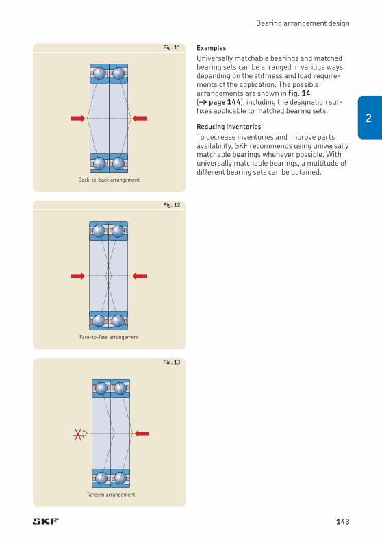
Bearing arrangement design
ExamplesUniversally matchable bearings and matched bearing sets can be arranged in various ways depending on the stiffness and load require-ments of the application. The possible arrangements are shown in fig. 14 († page 144), including the designation suf-fixes applicable to matched bearing sets.
Reducing inventoriesTo decrease inventories and improve parts availability, SKF recommends using universally matchable bearings whenever possible. With universally matchable bearings, a multitude of different bearing sets can be obtained.
Back-to-back arrangement
Fig. 11
Face-to-face arrangement
Fig. 12
Tandem arrangement
Fig. 13
143
2

Angular contact ball bearings
Bearing sets with 2 bearings
Bearing sets with 3 bearings
Back-to-back arrangementDesignation suffix DB
Back-to-back and tandemarrangementDesignation suffix TBT
Tandem back-to-back arrangementDesignation suffix QBC
Back-to-back and tandem arrangementDesignation suffix QBT
Tandem arrangementDesignation suffix DT
Tandem arrangementDesignation suffix TT
Tandem arrangementDesignation suffix QT
Face-to-face arrangementDesignation suffix DF
Face-to-face and tandem arrangementDesignation suffix TFT
Tandem face-to-face arrangementDesignation suffix QFC
Face-to-face and tandem arrangementDesignation suffix QFT
Bearing sets with 4 bearings
Fig. 14
144

Markings on bearings and bearing sets
Markings on bearings and bearing setsEach super-precision angular contact ball bearing has various markings on the side faces of the rings († fig. 15):
1 SKF trademark2 Complete designation of the bearing3 Country of manufacture4 Date of manufacture, coded5 Deviation of the mean outside diameter
ΔDm [µm] and position of the maximum eccentricity of the outer ring
6 Deviation of the mean bore diameter Δdm [µm] and position of the maximum eccentricity of the inner ring
7 Thrust face mark, punched8 Serial number (bearing sets only)9 “V-shaped” marking (matched bearing sets
only)
Sealed bearings are marked in a similar way.
“V-shaped” markingA “V-shaped” marking on the outside surface of the outer rings of matched bearing sets indi-cates how the bearings should be mounted to obtain the proper preload in the set.
The marking also indicates how the bearing set should be mounted in relation to the axial load. The “V-shaped” marking should point in the direction that the axial load acts on the inner ring († fig. 16). In applications where there are axial loads in both directions, the “V-shaped” marking should point in the direc-tion of the heavier of the two loads.
Fa
Fig. 16
Fig. 15
2
1
3
4
5
6
8
7
9
145
2

Angular contact ball bearings
Bearing dataBoundary dimensions
ISO 15
Chamfer dimensions
Minimum values for the chamfer dimensions in the radial direction (r1, r3) and axial direction (r2, r4) are listed in the product tables († page 198). The specifications differ according to the series.
718 .. D series• Values for the inner ring and thrust side of the outer ring: ISO 15• Values for the non-thrust side of the outer ring are not
standardized.
719 .. D, 70 .. D and 72 .. D series• Values for the inner ring and thrust side of the outer ring: ISO 15• Values for the non-thrust side of the outer ring: ISO 12044, where
applicable
719 .. E series• Values for the non-thrust side of the inner ring (d ≤ 30 mm), thrust
side of the inner ring, and thrust side of the outer ring: ISO 15. • Values for the non-thrust side of the inner ring (d > 30 mm): smaller
than those in accordance with ISO 15• Values for the non-thrust side of the outer ring: ISO 12044
70 .. E series• Values for the inner ring and thrust side of the outer ring: ISO 15• Values for the non-thrust side of the outer ring: ISO 12044
719 .. B and 70 .. B series• Values for the inner ring and thrust side of the outer ring: ISO 15• Values for the non-thrust side of the outer ring: smaller than those
in accordance with ISO 15
The appropriate maximum chamfer limits, which are important when dimensioning fillet radii on associated components, are in accordance with ISO 582 and are listed in the product tables.
Tolerances
For additional information († page 47)
P4A or P4 class tolerances as standard. PA9A or P2 class tolerances available on request.
The tolerance values are listed for:
• P4A class tolerances († table 6)• P4 class tolerances († table 7, page 148)• PA9A class tolerances († table 8, page 149)• P2 class tolerances († table 9, page 150)
146

Bearing data
Table 6
Class P4A tolerances
Inner ringd Δdmp Δds Vdp Vdmp ΔBs ΔB1s VBs Kia Sd Siaover incl. high low high low max. max. high low high low max. max. max. max.
mm µm µm µm µm µm µm µm µm µm µm
2,5 10 0 –4 0 –4 1,5 1 0 –40 0 –250 1,5 1,5 1,5 1,510 18 0 –4 0 –4 1,5 1 0 –80 0 –250 1,5 1,5 1,5 1,518 30 0 –5 0 –5 1,5 1 0 –120 0 –250 1,5 2,5 1,5 2,5
30 50 0 –6 0 –6 1,5 1 0 –120 0 –250 1,5 2,5 1,5 2,550 80 0 –7 0 –7 2 1,5 0 –150 0 –250 1,5 2,5 1,5 2,580 120 0 –8 0 –8 2,5 1,5 0 –200 0 –380 2,5 2,5 2,5 2,5
120 150 0 –10 0 –10 6 3 0 –250 0 –380 4 4 4 4150 180 0 –10 0 –10 6 3 0 –250 0 –380 4 6 5 6180 250 0 –12 0 –12 7 4 0 –300 0 –500 5 7 6 7
250 315 0 –13 0 –13 8 5 0 –350 0 –550 6 8 7 7315 400 0 –16 0 –16 10 6 0 –400 0 –600 6 9 8 8
Outer ringD ΔDmp ΔDs VDp
1) VDmp1) ΔCs, ΔC1s VCs Kea SD Sea
over incl. high low high low max. max. max. max. max. max.
mm µm µm µm µm µm µm µm µm
10 18 0 –4 0 –4 1,5 1 Values are identical to those for the inner ring of the same bearing (ΔBs, ΔB1s).
1,5 1,5 1,5 1,518 30 0 –5 0 –5 2 1,5 1,5 1,5 1,5 1,530 50 0 –6 0 –6 2 1,5 1,5 2,5 1,5 2,5
50 80 0 –7 0 –7 2 1,5 1,5 4 1,5 480 120 0 –8 0 –8 2,5 1,5 2,5 5 2,5 5120 150 0 –9 0 –9 4 1,5 2,5 5 2,5 5
150 180 0 –10 0 –10 6 3 4 6 4 6180 250 0 –11 0 –11 6 4 5 8 5 8250 315 0 –13 0 –13 8 5 5 9 6 8
315 400 0 –15 0 –15 9 6 7 10 8 10400 500 0 –20 0 –20 12 8 8 13 10 13
Tolerance symbols and definitions † table 4, page 481) For sealed bearings, values refer to the ring before the seals are installed.
147
2

Angular contact ball bearings
Table 7
Class P4 (ABEC 7) tolerances
Inner ringd Δdmp Δds Vdp Vdmp ΔBs ΔB1s VBs Kia Sd Siaover incl. high low high low max. max. high low high low max. max. max. max.
mm µm µm µm µm µm µm µm µm µm µm
2,5 10 0 –4 0 –4 4 2 0 –60 0 –250 2,5 2,5 3 310 18 0 –4 0 –4 4 2 0 –80 0 –250 2,5 2,5 3 318 30 0 –5 0 –5 5 2,5 0 –120 0 –250 2,5 3 4 4
30 50 0 –6 0 –6 6 3 0 –120 0 –250 3 4 4 450 80 0 –7 0 –7 7 3,5 0 –150 0 –250 4 4 5 580 120 0 –8 0 –8 8 4 0 –200 0 –380 4 5 5 5
120 150 0 –10 0 –10 10 5 0 –250 0 –380 5 6 6 7150 180 0 –10 0 –10 10 5 0 –250 0 –380 5 6 6 7
Outer ringD ΔDmp ΔDs VDp VDmp ΔCs, ΔC1s VCs Kea SD Seaover incl. high low high low max. max. max. max. max. max.
mm µm µm µm µm µm µm µm µm
18 30 0 –5 0 –5 5 2,5 Values are identical to those for the inner ring of the same bearing (ΔBs, ΔB1s).
2,5 4 4 530 50 0 –6 0 –6 6 3 2,5 5 4 550 80 0 –7 0 –7 7 3,5 3 5 4 5
80 120 0 –8 0 –8 8 4 4 6 5 6120 150 0 –9 0 –9 9 5 5 7 5 7150 180 0 –10 0 –10 10 5 5 8 5 8
180 250 0 –11 0 –11 11 6 7 10 7 10
Tolerance symbols and definitions † table 4, page 48
148

Bearing data
Table 8
Class PA9A tolerances
Inner ringd Δdmp Δds Vdp Vdmp ΔBs ΔB1s VBs Kia Sd Siaover incl. high low high low max. max. high low high low max. max. max. max.
mm µm µm µm µm µm µm µm µm µm µm
2,5 10 0 –2,5 0 –2,5 1,5 1 0 –40 0 –250 1,5 1,5 1,5 1,510 18 0 –2,5 0 –2,5 1,5 1 0 –80 0 –250 1,5 1,5 1,5 1,518 30 0 –2,5 0 –2,5 1,5 1 0 –120 0 –250 1,5 2,5 1,5 2,5
30 50 0 –2,5 0 –2,5 1,5 1 0 –120 0 –250 1,5 2,5 1,5 2,550 80 0 –4 0 –4 2 1,5 0 –150 0 –250 1,5 2,5 1,5 2,580 120 0 –5 0 –5 2,5 1,5 0 –200 0 –380 2,5 2,5 2,5 2,5
120 150 0 –7 0 –7 4 3 0 –250 0 –380 2,5 2,5 2,5 2,5150 180 0 –7 0 –7 4 3 0 –250 0 –380 4 5 4 5180 250 0 –8 0 –8 5 4 0 –300 0 –500 5 5 5 5
Outer ringD ΔDmp ΔDs VDp
1) VDmp1) ΔCs, ΔC1s VCs Kea SD Sea
over incl. high low high low max. max. max. max. max. max.
mm µm µm µm µm µm µm µm µm
10 18 0 –2,5 0 –2,5 1,5 1 Values are identical to those for the inner ring of the same bearing (ΔBs, ΔB1s).
1,5 1,5 1,5 1,518 30 0 –4 0 –4 2 1,5 1,5 1,5 1,5 1,530 50 0 –4 0 –4 2 1,5 1,5 2,5 1,5 2,5
50 80 0 –4 0 –4 2 1,5 1,5 4 1,5 480 120 0 –5 0 –5 2,5 1,5 2,5 5 2,5 5120 150 0 –5 0 –5 2,5 1,5 2,5 5 2,5 5
150 180 0 –7 0 –7 4 3 2,5 5 2,5 5180 250 0 –8 0 –8 5 4 4 7 4 7250 315 0 –8 0 –8 5 4 5 7 5 7
315 400 0 –10 0 –10 6 5 7 8 7 8
Tolerance symbols and definitions † table 4, page 481) For sealed bearings, values refer to the ring before the seals are installed.
149
2

Angular contact ball bearings
Table 9
Class P2 (ABEC 9) tolerances
Inner ringd Δdmp Δds Vdp Vdmp ΔBs ΔB1s VBs Kia Sd Siaover incl. high low high low max. max. high low high low max. max. max. max.
mm µm µm µm µm µm µm µm µm µm µm
2,5 10 0 –2,5 0 –2,5 2,5 1,5 0 –40 0 –250 1,5 1,5 1,5 1,510 18 0 –2,5 0 –2,5 2,5 1,5 0 –80 0 –250 1,5 1,5 1,5 1,518 30 0 –2,5 0 –2,5 2,5 1,5 0 –120 0 –250 1,5 2,5 1,5 2,5
30 50 0 –2,5 0 –2,5 2,5 1,5 0 –120 0 –250 1,5 2,5 1,5 2,550 80 0 –4 0 –4 4 2 0 –150 0 –250 1,5 2,5 1,5 2,580 120 0 –5 0 –5 5 2,5 0 –200 0 –380 2,5 2,5 2,5 2,5
120 150 0 –7 0 –7 7 3,5 0 –250 0 –380 2,5 2,5 2,5 2,5150 180 0 –7 0 –7 7 3,5 0 –250 0 –380 4 5 4 5
Outer ringD ΔDmp ΔDs VDp VDmp ΔCs, ΔC1s VCs Kea SD Seaover incl. high low high low max. max. max. max. max. max.
mm µm µm µm µm µm µm µm µm
18 30 0 –4 0 –4 4 2 Values are identical to those for the inner ring of the same bearing (ΔBs, ΔB1s).
1,5 2,5 1,5 2,530 50 0 –4 0 –4 4 2 1,5 2,5 1,5 2,550 80 0 –4 0 –4 4 2 1,5 4 1,5 4
80 120 0 –5 0 –5 5 2,5 2,5 5 2,5 5120 150 0 –5 0 –5 5 2,5 2,5 5 2,5 5150 180 0 –7 0 –7 7 3,5 2,5 5 2,5 5
180 250 0 –8 0 –8 8 4 4 7 4 7
Tolerance symbols and definitions † table 4, page 48
150

Preload
PreloadA single super-precision angular contact ball bearing cannot be preloaded until a second bearing provides location in the opposite direc-tion. Detailed information about preload is provided in the sections following.
Bearings manufactured pre-set for preloadUniversally matchable bearings and matched bearing sets are manufactured pre-set in dif-ferent preload classes to meet varying require-ments regarding rotational speed, rigidity, and operating temperature.
The amount of preload depends on the bear-ing series, the contact angle, the internal geometry, and the size of the bearing and applies to bearing sets in back-to-back or face-to-face arrangements. Preload values are not standardized and are listed in the following tables:
• table 10 († page 153) for bearings in the 718 .. D series
• table 11 († page 154) for bearings in the 719 .. D and 70 .. D series
• table 12 († page 156) for bearings in the 719 .. E and 70 .. E series
• table 13 († page 158) for bearings in the 719 .. B and 70 .. B series
• table 14 († page 160) for bearings in the 72 .. D series
Matched bearing sets with a special preload can be supplied on request. These bearing sets are identified by the designation suffix G fol-lowed by a number. The number is the mean preload value of the set expressed in daN. Spe-cial preload is not applicable for sets of univer-sally matchable bearings consisting of three or more bearings. Matched bearing sets consist-ing of three or more bearings have a heavier preload than sets with two bearings. The preload for these bearing sets is obtained by multiplying the values for a single bearing by a factor listed in table 15 († page 161).
719 .. D, 70 .. D and 72 .. D seriesBearings in the 719 .. D, 70 .. D and 72 .. D series are manufactured to four different preload classes:
• class A, extra light preload• class B, light preload• class C, moderate preload• class D, heavy preload
718 .. D, 719 .. E and 70 .. E seriesBearings in the 718 .. D, 719 .. E and 70 .. E series are manufactured to three different preload classes:
• class A, light preload• class B, moderate preload• class C, heavy preload
These preload classes are valid for:
• single, universally matchable bearings• sets of universally matchable bearings• matched bearing sets
In applications where high speeds take pre ce-dence over the degree of rigidity, the following additional preload classes are available:
• class L, reduced light preload for asymmet-rical bearing sets
• class M, reduced moderate preload for asymmetrical bearing sets
• class F, reduced heavy preload for asymmet-rical bearing sets
As indicated, these preload classes are only available for matched bearing sets that are asymmetrical, e.g. TBT, TFT, QBT, and QFT. Bearing sets in the L, M or F preload class con-sisting of three or four bearings, have the same preload as sets with two bearings in the A, B or C preload class. Therefore, the preload for matched bearing sets that are asymmetrical, e.g. TBT, TFT, QBT, and QFT, can be obtained directly from the product tables.
An example of the preload possibilities for an arrangement with a matched set of 7014 CE bearings is presented in table 16 († page 161).
151
2

Angular contact ball bearings
719 .. B and 70 .. B seriesBearings in the 719 .. B and 70 .. B series are manufactured to three different preload classes:
• class A, light preload• class B, moderate preload• class C, heavy preload
152

Preload
Table 10
Axial preload of single, universally matchable bearings and matched bearing pairs prior to mounting, arranged back-to-back or face-to-face – 718 .. D series
Bore diameter
Size Axial preload of bearings in the series1)
718 CD, 718 CD/HC 718 ACD, 718 ACD/HCfor preload class for preload class
d A B C A B C
mm – N
10 00 10 30 60 16 48 10012 01 11 33 66 17 53 10515 02 12 36 72 19 58 115
17 03 12 37 75 20 60 12020 04 20 60 120 32 100 20025 05 22 66 132 35 105 210
30 06 23 70 140 37 110 22035 07 25 75 150 39 115 23040 08 26 78 155 40 120 240
45 09 27 80 160 41 125 25050 10 40 120 240 60 180 36055 11 55 165 330 87 260 520
60 12 70 210 420 114 340 68065 13 71 215 430 115 345 69070 14 73 220 440 117 350 700
75 15 76 225 450 120 360 72080 16 78 235 470 123 370 74085 17 115 345 690 183 550 1 100
90 18 116 350 700 184 555 1 11095 19 117 355 710 186 560 1 120100 20 120 360 720 190 570 1 140
105 21 130 390 780 200 600 1 200110 22 160 500 1 000 260 800 1 600120 24 180 550 1 100 280 850 1 700
130 26 210 620 1 230 325 980 1 960140 28 240 720 1 440 380 1 140 2 280150 30 270 820 1 630 430 1 300 2 590
160 32 280 850 1 700 450 1 350 2 690
1) The designation suffix HC denotes a hybrid bearing. For additional information, refer to Hybrid bearings, page 133.
153
2

Angular contact ball bearings
Table 11a
Axial preload of single, universally matchable bearings and matched bearing pairs prior to mounting, arranged back-to-back or face-to-face – 719 .. D series
Bore diameter
Size Axial preload of bearings in the series1)
719 CD, 719 CD/HC 719 ACD, 719 ACD/HCfor preload class for preload class
d A B C D A B C D
mm – N
10 00 10 20 40 80 15 30 60 12012 01 10 20 40 80 15 30 60 12015 02 15 30 60 120 25 50 100 20017 03 15 30 60 120 25 50 100 200
20 04 25 50 100 200 35 70 140 28025 05 25 50 100 200 40 80 160 32030 06 25 50 100 200 40 80 160 32035 07 35 70 140 280 60 120 240 480
40 08 45 90 180 360 70 140 280 56045 09 50 100 200 400 80 160 320 64050 10 50 100 200 400 80 160 320 64055 11 70 140 280 560 120 240 480 960
60 12 70 140 280 560 120 240 480 96065 13 80 160 320 640 120 240 480 96070 14 130 260 520 1 040 200 400 800 1 60075 15 130 260 520 1 040 210 420 840 1 680
80 16 140 280 560 1 120 220 440 880 1 76085 17 170 340 680 1 360 270 540 1 080 2 16090 18 180 360 720 1 440 280 560 1 120 2 24095 19 190 380 760 1 520 290 580 1 160 2 320
100 20 230 460 920 1 840 360 720 1 440 2 880105 21 230 460 920 1 840 360 720 1 440 2 880110 22 230 460 920 1 840 370 740 1 480 2 960120 24 290 580 1 160 2 320 450 900 1 800 3 600
130 26 350 700 1 400 2 800 540 1 080 2 160 4 320140 28 360 720 1 440 2 880 560 1 120 2 240 4 480150 30 470 940 1 880 3 760 740 1 480 2 960 5 920160 32 490 980 1 960 3 920 800 1 600 3 200 6 400
170 34 500 1 000 2 000 4 000 800 1 600 3 200 6 400180 36 630 1 260 2 520 5 040 1 000 2 000 4 000 8 000190 38 640 1 280 2 560 5 120 1 000 2 000 4 000 8 000200 40 800 1 600 3 200 6 400 1 250 2 500 5 000 10 000
220 44 850 1 700 3 400 6 800 1 300 2 600 5 200 10 400240 48 860 1 720 3 440 6 880 1 430 2 860 5 720 11 440260 52 1 050 2 100 4 200 8 400 1 730 3 460 6 920 13 840280 56 1 090 2 180 4 360 8 720 1 820 3 640 7 280 14 560
300 60 1 400 2 800 5 600 11 200 2 200 4 400 8 800 17 600320 64 1 400 2 800 5 600 11 200 2 200 4 400 8 800 17 600340 68 1 460 2 920 5 840 11 680 2 300 4 600 9 200 18 400360 72 1 460 2 920 5 840 11 680 2 300 4 600 9 200 18 400
1) The designation suffix HC denotes a hybrid bearing. For additional information, refer to Hybrid bearings, page 133.
154

Preload
Table 11b
Axial preload of single, universally matchable bearings and matched bearing pairs prior to mounting, arranged back-to-back or face-to-face – 70 .. D series
Bore diameter
Size Axial preload of bearings in the series1)
70 CD, 70 CD/HC 70 ACD, 70 ACD/HCfor preload class for preload class
d A B C D A B C D
mm – N
6 6 7 13 25 50 12 25 50 1007 7 9 18 35 70 15 30 60 1208 8 11 22 45 90 20 40 80 1609 9 12 25 50 100 22 45 90 180
10 00 15 30 60 120 25 50 100 20012 01 15 30 60 120 25 50 100 20015 02 20 40 80 160 30 60 120 24017 03 25 50 100 200 40 80 160 320
20 04 35 70 140 280 50 100 200 40025 05 35 70 140 280 60 120 240 48030 06 50 100 200 400 90 180 360 72035 07 60 120 240 480 90 180 360 720
40 08 60 120 240 480 100 200 400 80045 09 110 220 440 880 170 340 680 1 36050 10 110 220 440 880 180 360 720 1 44055 11 150 300 600 1 200 230 460 920 1 840
60 12 150 300 600 1 200 240 480 960 1 92065 13 160 320 640 1 280 240 480 960 1 92070 14 200 400 800 1 600 300 600 1 200 2 40075 15 200 400 800 1 600 310 620 1 240 2 480
80 16 240 480 960 1 920 390 780 1 560 3 12085 17 250 500 1 000 2 000 400 800 1 600 3 20090 18 300 600 1 200 2 400 460 920 1 840 3 68095 19 310 620 1 240 2 480 480 960 1 920 3 840
100 20 310 620 1 240 2 480 500 1 000 2 000 4 000105 21 360 720 1 440 2 880 560 1 120 2 240 4 480110 22 420 840 1 680 3 360 650 1 300 2 600 5 200120 24 430 860 1 720 3 440 690 1 380 2 760 5 520
130 26 560 1 120 2 240 4 480 900 1 800 3 600 7 200140 28 570 1 140 2 280 4 560 900 1 800 3 600 7 200150 30 650 1 300 2 600 5 200 1 000 2 000 4 000 8 000160 32 730 1 460 2 920 5 840 1 150 2 300 4 600 9 200
170 34 800 1 600 3 200 6 400 1 250 2 500 5 000 10 000180 36 900 1 800 3 600 7 200 1 450 2 900 5 800 11 600190 38 950 1 900 3 800 7 600 1 450 2 900 5 800 11 600200 40 1 100 2 200 4 400 8 800 1 750 3 500 7 000 14 000
220 44 1 250 2 500 5 000 10 000 2 000 4 000 8 000 16 000240 48 1 300 2 600 5 200 10 400 2 050 4 100 8 200 16 400260 52 1 550 3 100 6 200 12 400 2 480 4 960 9 920 19 840
1) The designation suffix HC denotes a hybrid bearing. For additional information, refer to Hybrid bearings, page 133.
155
2

Angular contact ball bearings
Table 12a
Axial preload of single, universally matchable bearings and matched bearing pairs prior to mounting, arranged back-to-back or face-to-face – 719 .. E series
Bore diameter
Size Axial preload of bearings in the series1)
719 CE, 719 CE/HC 719 ACE, 719 ACE/HCfor preload class for preload class
d A B C A B C
mm – N
8 8 9 27 55 15 46 919 09 11 32 64 17 50 10010 00 11 32 65 17 50 100
12 01 11 34 68 18 55 11015 02 17 51 102 28 84 17017 03 18 54 108 29 87 175
20 04 26 79 157 42 130 25025 05 28 85 170 45 140 27030 06 30 90 180 48 145 290
35 07 41 125 250 66 200 40040 08 52 157 315 84 250 50545 09 55 166 331 88 265 529
50 10 69 210 410 110 330 66055 11 83 250 500 133 400 80060 12 87 262 523 139 418 836
65 13 89 266 532 142 425 85070 14 120 360 710 190 570 1 13075 15 120 361 722 192 577 1 150
80 16 123 370 740 195 590 1 17085 17 160 479 957 255 765 1 52990 18 163 488 977 260 780 1 560
95 19 166 500 995 265 795 1 590100 20 208 624 1 250 332 996 1 990110 22 220 650 1 300 340 1 030 2 070
120 24 250 760 1 530 410 1 220 2 440
1) The designation suffix HC denotes a hybrid bearing. For additional information, refer to Hybrid bearings, page 133.
156

Preload
1) The designation suffix HC denotes a hybrid bearing. For additional information, refer to Hybrid bearings, page 133.
Table 12b
Axial preload of single, universally matchable bearings and matched bearing pairs prior to mounting, arranged back-to-back or face-to-face – 70 .. E series
Bore diameter
Size Axial preload of bearings in the series1)
70 CE, 70 CE/HC 70 ACE, 70 ACE/HCfor preload class for preload class
d A B C A B C
mm – N
6 6 10 25 50 14 41 827 7 10 30 60 17 50 1008 8 15 35 75 20 60 120
9 09 15 40 80 23 65 13010 00 15 48 95 26 80 16012 01 17 53 110 28 85 170
15 02 25 70 140 38 115 23017 03 30 90 185 50 150 30020 04 40 120 235 64 193 390
25 05 45 130 260 70 210 43030 06 50 150 300 80 240 48035 07 60 180 370 100 300 590
40 08 65 200 390 105 310 63045 09 70 210 410 110 330 66050 10 85 250 500 130 400 800
55 11 90 270 540 140 430 86060 12 92 275 550 150 440 87065 13 110 330 650 170 520 1 040
70 14 130 380 760 200 610 1 22075 15 140 420 840 220 670 1 34080 16 180 550 1 090 280 850 1 700
85 17 185 560 1 110 290 890 1 78090 18 190 580 1 150 300 920 1 84095 19 230 700 1 400 380 1 130 2 270
100 20 240 720 1 440 390 1 150 2 310110 22 250 760 1 520 400 1 210 2 420120 24 310 930 1 850 490 1 480 2 950
157
2
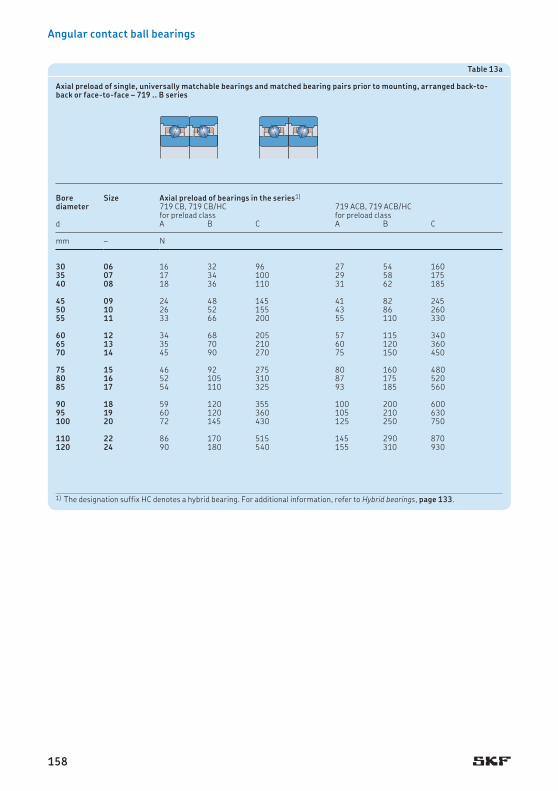
Angular contact ball bearings
Table 13a
Axial preload of single, universally matchable bearings and matched bearing pairs prior to mounting, arranged back-to-back or face-to-face – 719 .. B series
Bore diameter
Size Axial preload of bearings in the series1)
719 CB, 719 CB/HC 719 ACB, 719 ACB/HCfor preload class for preload class
d A B C A B C
mm – N
30 06 16 32 96 27 54 16035 07 17 34 100 29 58 17540 08 18 36 110 31 62 185
45 09 24 48 145 41 82 24550 10 26 52 155 43 86 26055 11 33 66 200 55 110 330
60 12 34 68 205 57 115 34065 13 35 70 210 60 120 36070 14 45 90 270 75 150 450
75 15 46 92 275 80 160 48080 16 52 105 310 87 175 52085 17 54 110 325 93 185 560
90 18 59 120 355 100 200 60095 19 60 120 360 105 210 630100 20 72 145 430 125 250 750
110 22 86 170 515 145 290 870120 24 90 180 540 155 310 930
1) The designation suffix HC denotes a hybrid bearing. For additional information, refer to Hybrid bearings, page 133.
158

Preload
1) The designation suffix HC denotes a hybrid bearing. For additional information, refer to Hybrid bearings, page 133.
Table 13b
Axial preload of single, universally matchable bearings and matched bearing pairs prior to mounting, arranged back-to-back or face-to-face – 70 .. B series
Bore diameter
Size Axial preload of bearings in the series1)
70 CB, 70 CB /HC 70 ACB, 70 ACB/HCfor preload class for preload class
d A B C A B C
mm – N
30 06 21 42 125 36 72 21535 07 23 46 140 38 76 23040 08 24 48 145 41 82 245
45 09 31 62 185 54 110 33050 10 33 66 200 56 110 33055 11 46 92 275 78 155 470
60 12 48 96 290 80 160 48065 13 49 98 295 85 170 51070 14 64 130 390 110 220 660
75 15 65 130 390 115 230 69080 16 78 155 470 150 300 90085 17 80 160 480 150 300 900
90 18 92 185 550 160 320 96095 19 94 190 570 165 330 990100 20 96 190 570 165 330 990
110 22 125 250 750 210 420 1 260120 24 130 260 780 220 440 1 320
159
2

Angular contact ball bearings
Table 14
Axial preload of single, universally matchable bearings and matched bearing pairs prior to mounting, arranged back-to-back or face-to-face – 72 .. D series
Bore diameter
Size Axial preload of bearings in the series1)
72 CD, 72 CD/HC 72 ACD, 72 ACD/HCfor preload class for preload class
d A B C D A B C D
mm – N
7 7 12 24 48 96 18 36 72 1448 8 14 28 56 112 22 44 88 1769 9 15 30 60 120 25 50 100 200
10 00 17 34 68 136 27 54 108 21612 01 22 44 88 176 35 70 140 28015 02 30 60 120 240 45 90 180 360
17 03 35 70 140 280 60 120 240 48020 04 45 90 180 360 70 140 280 56025 05 50 100 200 400 80 160 320 640
30 06 90 180 360 720 150 300 600 1 20035 07 120 240 480 960 190 380 760 1 52040 08 125 250 500 1 000 200 400 800 1 600
45 09 160 320 640 1 280 260 520 1 040 2 08050 10 170 340 680 1 360 265 530 1 060 2 12055 11 210 420 840 1 680 330 660 1 320 2 640
60 12 215 430 860 1 720 350 700 1 400 2 80065 13 250 500 1 000 2 000 400 800 1 600 3 20070 14 260 520 1 040 2 080 420 840 1 680 3 360
75 15 270 540 1 080 2 160 430 860 1 720 3 44080 16 320 640 1 280 2 560 520 1 040 2 080 4 16085 17 370 740 1 480 2 960 600 1 200 2 400 4 800
90 18 480 960 1 920 3 840 750 1 500 3 000 6 00095 19 520 1 040 2 080 4 160 850 1 700 3 400 6 800100 20 590 1 180 2 360 4 720 950 1 900 3 800 7 600
105 21 650 1 300 2 600 5 200 1 000 2 000 4 000 8 000110 22 670 1 340 2 680 5 360 1 050 2 100 4 200 8 400120 24 750 1 500 3 000 6 000 1 200 2 400 4 800 9 600
130 26 810 1 620 3 240 6 480 1 300 2 600 5 200 10 400140 28 850 1 700 3 400 6 800 1 350 2 700 5 400 10 800
1) The designation suffix HC denotes a hybrid bearing. For additional information, refer to Hybrid bearings, page 133.
160

Preload
Table 15
Factors for calculating the preload of a bearing set
Number of bearings
Arrangement Designation suffix Factorfor preload class
A, B, C and D L, M and F
3 Back-to-back and tandem TBT 1,35 1Face-to-face and tandem TFT 1,35 1
4 Back-to-back and tandem QBT 1,6 1Face-to-face and tandem QFT 1,6 1Tandem back-to-back QBC 2 2Tandem face-to-face QFC 2 2
5 Back-to-back and tandem PBT 1,75 1Face-to-face and tandem PFT 1,75 1Tandem back-to-back PBC 2,45 2Tandem face-to-face PFC 2,45 2
Table 16
Example of the (light) preload possibilities for an arrangement with a matched set of 7014 CE bearings
Number of bearings
Arrangement Preload of a matched set, prior to mountingfor maximum rigidity for maximum speedDesignation suffix
Preload Designation suffix
Preload
– – – N – N
2 Back-to-back DBA 130 – –Face-to-face DFA 130 – –
3 Back-to-back and tandem TBTA 175,5 TBTL 130Face-to-face and tandem TFTA 175,5 TFTL 130
4 Tandem back-to-back QBCA 260 – –Tandem face-to-face QFCA 260 – –Back-to-back and tandem QBTA 208 QBTL 130Face-to-face and tandem QFTA 208 QFTL 130
For symmetrical arrangements, preload class A = preload class L e .g. the designation suffix DBL does not exist.For bearing sets with five bearings, contact the SKF application engineering service.
161
2

Angular contact ball bearings
Preload in mounted bearing setsAfter mounting, sets of universally matchable bearings and matched bearing sets can have a heavier preload than the pre-set preload, pre-determined during manufacture. The increase in preload depends mainly on the actual toler-ances for the shaft and housing seats and whether these result in an interference fit with the bearing rings.
An increase in preload can also be caused by deviations from the geometrical form of asso-ciated components, such as cylindricity, per-pendicularity or concentricity of the bearing seats.
During operation, an additional increase in preload can also be caused by:
• the centrifugal force caused by the rota-tional speed of the shaft, for constant pos-ition arrangements
• a temperature difference between the inner ring, outer ring, and balls
• different coefficient of thermal expansion for the shaft and housing materials compared to bearing steel
If the bearings are mounted with zero interfer-ence on a steel shaft and in a thick-walled steel or cast iron housing, preload can be deter-mined with sufficient accuracy from
Gm = f f1 f2 fHC GA,B,C,D
whereGm = preload in the mounted bearing
set [N]GA,B,C,D = pre-set preload in the bearing set,
prior to mounting († tables 10 to 14, pages 153 to 160) [N]
f = bearing factor dependent on the bearing series and size († table 17)
f1 = correction factor dependent on the contact angle († table 18, page 164)
f2 = correction factor dependent on the preload class († table 18)
fHC = correction factor for hybrid bearings († table 18)
Considerably tighter fits may be necessary, for example, for very high speed spindles, where centrifugal forces can loosen the inner ring fit on its shaft seat. These bearing arrangements
must be carefully evaluated. In these cases, contact the SKF application engineering service.
Calculation exampleWhat is the preload in a matched bearing set 71924 CD/P4ADBC after mounting?
The pre-set preload for the set of two bear-ings in the 719 CD series, prior to mounting, preload class C, size 24 is GC = 1 160 N († table 11, page 154).
With the bearing factor f = 1,26 († table 17) and correction factors f1 = 1 and f2 = 1,09 († table 18, page 164), the preload of the mounted bearing set is
Gm = f f1 f2 GC= 1,26 × 1 × 1,09 × 1 160≈ 1 590 N
162

Preload
Table 17
Bearing factor f for calculating the preload in mounted bearing sets
Bore diameter
Size Bearing factor of bearings in the series718 .. D 719 .. D 719 .. E 719 .. B 70 .. D 70 .. E 70 .. B 72 .. D
d
mm – –
6 6 – – – – 1,01 1,02 – –7 7 – – – – 1,02 1,02 – 1,028 8 – – 1,02 – 1,02 1,02 – 1,02
9 9 – – 1,03 – 1,03 1,02 – 1,0210 00 1,05 1,03 1,03 – 1,03 1,03 – 1,0212 01 1,06 1,04 1,04 – 1,03 1,02 – 1,02
15 02 1,08 1,05 1,04 – 1,03 1,03 – 1,0317 03 1,1 1,05 1,05 – 1,04 1,04 – 1,0320 04 1,08 1,05 1,04 – 1,03 1,04 – 1,03
25 05 1,11 1,07 1,06 – 1,05 1,05 – 1,0330 06 1,14 1,08 1,08 1,07 1,06 1,05 1,03 1,0535 07 1,18 1,1 1,05 1,06 1,06 1,06 1,04 1,05
40 08 1,23 1,09 1,05 1,06 1,06 1,06 1,04 1,0545 09 1,24 1,11 1,09 1,08 1,09 1,06 1,05 1,0750 10 1,3 1,13 1,15 1,09 1,11 1,08 1,06 1,08
55 11 1,27 1,15 1,16 1,09 1,1 1,07 1,06 1,0860 12 1,3 1,17 1,13 1,11 1,12 1,08 1,06 1,0765 13 1,28 1,2 1,19 1,13 1,13 1,09 1,07 1,07
70 14 1,32 1,19 1,14 1,1 1,12 1,09 1,07 1,0875 15 1,36 1,21 1,16 1,11 1,14 1,1 1,08 1,0880 16 1,41 1,24 1,19 1,13 1,13 1,1 1,07 1,09
85 17 1,31 1,2 1,16 1,11 1,15 1,11 1,08 1,0890 18 1,33 1,23 1,19 1,12 1,14 1,1 1,07 1,0995 19 1,36 1,26 1,18 1,13 1,15 1,11 1,07 1,09
100 20 1,4 1,23 1,18 1,11 1,16 1,12 1,08 1,09105 21 1,44 1,25 – – 1,15 – – 1,08110 22 1,34 1,26 1,2 1,14 1,14 1,1 1,07 1,08
120 24 1,41 1,26 1,18 1,13 1,17 1,12 1,08 1,08130 26 1,34 1,25 – – 1,15 – – 1,09140 28 1,43 1,29 – – 1,16 – – 1,09
150 30 1,37 1,24 – – 1,16 – – –160 32 1,42 1,27 – – 1,16 – – –170 34 – 1,3 – – 1,14 – – –
180 36 – 1,25 – – 1,13 – – –190 38 – 1,27 – – 1,14 – – –200 40 – 1,23 – – 1,14 – – –
220 44 – 1,28 – – 1,13 – – –240 48 – 1,32 – – 1,15 – – –260 52 – 1,24 – – 1,13 – – –
280 56 – 1,27 – – – – – –300 60 – 1,22 – – – – – –320 64 – 1,24 – – – – – –
340 68 – 1,27 – – – – – –360 72 – 1,29 – – – – – –
163
2

Angular contact ball bearings
Table 18
Correction factors for preload calculation in mounted bearing sets
Bearing series Correction factorsf1 f2 fHC
for preload class A B C D
718 CD 1 1 1,09 1,16 – 1718 ACD 0,97 1 1,08 1,15 – 1718 CD/HC 1 1 1,1 1,18 – 1,02718 ACD/HC 0,97 1 1,09 1,17 – 1,02
719 CD 1 1 1,04 1,09 1,15 1719 ACD 0,98 1 1,04 1,08 1,14 1719 CD/HC 1 1 1,07 1,12 1,18 1,04719 ACD/HC 0,98 1 1,07 1,12 1,17 1,04
719 CE 1 1 1,04 1,08 – 1719 ACE 0,99 1 1,04 1,07 – 1719 CE/HC 1 1 1,05 1,09 – 1,01719 ACE/HC 0,98 1 1,04 1,08 – 1,01
719 CB 1 1 1,02 1,07 – 1719 ACB 0,99 1 1,02 1,07 – 1719 CB/HC 1 1 1,03 1,08 – 1,01719 ACB/HC 0,99 1 1,02 1,08 – 1,01
70 CD 1 1 1,02 1,05 1,09 170 ACD 0,99 1 1,02 1,05 1,08 170 CD/HC 1 1 1,02 1,05 1,09 1,0270 ACD/HC 0,99 1 1,02 1,05 1,08 1,02
70 CE 1 1 1,03 1,05 – 170 ACE 0,99 1 1,03 1,06 – 170 CE/HC 1 1 1,03 1,05 – 1,0170 ACE/HC 0,99 1 1,03 1,06 – 1,01
70 CB 1 1 1,02 1,05 – 170 ACB 0,99 1 1,01 1,04 – 170 CB/HC 1 1 1,02 1,05 – 1,0170 ACB/HC 0,99 1 1,02 1,05 – 1,01
72 CD 1 1 1,01 1,03 1,05 172 ACD 0,99 1 1,01 1,02 1,05 172 CD/HC 1 1 1,01 1,03 1,06 1,0172 ACD/HC 0,99 1 1,01 1,03 1,06 1,01
The designation suffix HC denotes a hybrid bearing. For additional information, refer to Hybrid bearings, page 133.
164

Preload
Table 19
Guideline values for spring preload forces for bearings in the 70 .. E series
Bore diameter
Size Preload1)
CE design ACE designd
mm – N
6 6 50 807 7 60 1008 8 70 1209 9 80 13010 00 90 140
12 01 90 15015 02 120 20017 03 160 25020 04 200 320
25 05 220 35030 06 240 40035 07 300 48040 08 320 500
45 09 340 54050 10 400 65055 11 420 70060 12 450 700
65 13 520 84070 14 600 1 00075 15 700 1 10080 16 900 1 400
85 17 900 1 40090 18 900 1 50095 19 1 200 1 900100 20 1 200 1 900
110 22 1 200 2 000120 24 1 500 2 400
1) For single bearings in the CE and ACE designs.For tandem bearing arrangements, the values should be multiplied by a factor equal to the number of bearings.
Preload with a constant forceIn precision, high-speed applications, a con-stant, uniform preload is important. To main-tain the proper preload, calibrated linear springs are typically used between the bearing outer ring and housing shoulder († fig. 17). With springs, the kinematic behaviour of the bearing does not influence preload under nor-mal operating conditions. However, a spring-loaded bearing arrangement has a lower degree of stiffness than an arrangement using axial displacement to set the preload. The spring preload method is standard for spindles used on internal grinders.
Guideline values for the most common spring-loaded bearing arrangements are listed in table 19. The values apply to single CE and ACE design bearings. For bearings in tandem arrangements, the values should be multiplied by a factor equal to the number of bearings preloaded with the spring force. The specified spring preload forces are a compromise between minimal difference in operating con-tact angle at the inner and outer ring raceways, and axial rigidity at high rotational speeds. Heavier preloads lead to higher operating temperatures.
For additional information, contact the SKF application engineering service.
Fig. 17
165
2

Angular contact ball bearings
Preload by axial displacementFor machining centres, milling machines, lathes, and drills, rigidity and precise axial guidance are critical parameters, especially when alternating axial loads occur. For these applications, the preload in the bearings is usually obtained by adjusting the bearing rings relative to each other in the axial direction.
This preload method offers significant advantages in terms of system rigidity. How-ever, depending on the bearing internal design and ball material, preload increases consider-ably with rotational speed as a result of cen-trifugal forces.
Universally matchable bearings or matched bearing sets are manufactured so that when mounted properly, they attain their predeter-mined axial displacement and proper preload values († fig. 18). With single bearings, preci-sion matched spacer rings must be used.
Individual adjustment of preloadIn cases where universally matchable bearings or matched bearing sets are used, preload is determined at the factory during production. In some cases, however, it may be necessary to optimize the preload to accommodate the par-ticular operating conditions. In these cases, the bearings should not be modified, as this requires special tools and knowledge, and the bearings could be damaged irreparably. Bear-ing modification should be entrusted exclu-sively to SKF Spindle Service Centres († skf.com).
It is possible, however, to increase or decrease preload by using spacer rings between two bearings arranged back-to-back or face-to-face, when used in sets of two or more bearings. There is no requirement to insert spacers between bearings arranged in tandem.
By grinding the side face of the inner or outer spacer, the preload in the bearing set can be changed.
Table 20 provides information about which of the equal-width spacer ring side faces must be ground and what effect it has. The neces-sary dimensional deviation for the overall width of the spacer rings is listed in the follow-ing tables:
• table 21 († page 168) for bearings in the 718 .. D series
• table 22 († page 169) for bearings in the 719 .. D and 70 .. D series
• table 23 († page 170) for bearings in the 719 .. E and 70 .. E series
• table 24 († page 171) for bearings in the 719 .. B and 70 .. B series
• table 25 († page 172) for bearings in the 72 .. D series
Fig. 18
166

Preload
Table 20
Guidelines for spacer ring modification
Preload change of a bearing set
Width reduction Requisite spacer ring between bearings arrangedValue back-to-back face-to-face
Increasing the preloadfrom A to B a inner outerfrom B to C b inner outerfrom C to D c inner outerfrom A to C a + b inner outerfrom A to D a + b + c inner outer
Decreasing the preloadfrom B to A a outer innerfrom C to B b outer innerfrom D to C c outer innerfrom C to A a + b outer innerfrom D to A a + b + c outer inner
Spacer ringsAs a rule, using spacer rings with angular con-tact ball bearing sets is advantageous when:
• preload in the bearing set needs to be adjusted
• moment stiffness and moment load capacity should be increased
• nozzles for oil lubrication must be as close as possible to the bearing raceways
• sufficiently large space is needed for surplus grease, in order to reduce frictional heat in the bearing
• improved heat dissipation via the housing is required at very high operating speeds
To achieve optimum bearing performance, spacer rings must not deform under load, other-wise form deviations can influence the preload in the bearing set. As a result, the guideline values for the shaft and housing tolerances should always be used.
Spacer rings should be made of high-grade steel that can be hardened to between 45 and 60 HRC, depending on the application. Plane parallelism of the face surfaces is particularly important. The permissible deviation must not exceed 1 to 2 µm.
Unless preload is to be adjusted, the overall width of the inner and outer spacer rings should be identical. The most accurate way to do this is to process the width of the concentric inner and outer spacer rings in one operation.
Effect of rotational speed on preloadUsing strain gauges, SKF has determined that preload changes with rotational speed and that there is a marked increase in preload at very high rotational speeds. This is mainly attribut-able to the heavy centrifugal forces on the balls causing them to change their position in the raceways.
When compared to a bearing with steel balls, a hybrid bearing (bearing with ceramic balls) can attain much higher rotational speeds, without significantly increasing preload, as a result of the lower mass of the balls.
167
2

Angular contact ball bearings
Table 21
Guideline values for spacer ring width reduction – 718 .. D bearing series
Bore diameter
Size Requisite spacer ring width reduction of bearings in the series718 CD 718 ACD
d a b a b
mm – µm
10 00 5 5 4 412 01 5 5 4 415 02 5 5 4 4
17 03 5 5 4 420 04 6 6 4 525 05 6 6 4 5
30 06 6 6 4 535 07 6 6 4 540 08 6 6 4 5
45 09 6 6 4 550 10 8 8 5 655 11 9 9 6 7
60 12 10 11 7 865 13 10 11 7 870 14 10 11 7 8
75 15 10 11 7 880 16 10 11 7 885 17 13 13 9 10
90 18 13 14 9 1095 19 13 14 9 10100 20 13 14 9 10
105 21 14 14 9 10110 22 16 16 10 12120 24 16 17 11 12
130 26 16 17 11 12140 28 18 20 12 14150 30 19 20 13 14160 32 19 20 13 15
a, b
a, b a, b
a, b
Increasing the preload (back-to-back)
Decreasing the preload (back-to-back)
Increasing the preload (face-to-face)
Decreasing the preload (face-to-face)
168

Preload
Decreasing the preload (face-to-face)
Table 22
Guideline values for spacer ring width reduction – 719 .. D and 70 .. D bearing series
Bore diameter
Size Requisite spacer ring width reduction of bearings in the series719 CD 719 ACD 70 CD 70 ACD
d a b c a b c a b c a b c
mm – µm
6 6 – – – – – – 3 4 7 2 4 57 7 – – – – – – 4 5 8 2 4 68 8 – – – – – – 4 6 8 3 4 69 9 – – – – – – 4 6 8 3 4 610 00 3 4 6 2 3 5 4 6 9 3 4 712 01 3 4 6 2 3 5 4 6 9 3 4 715 02 4 5 8 2 4 6 4 6 9 3 4 717 03 4 5 8 2 4 6 5 7 10 3 5 720 04 4 6 9 3 4 6 6 8 12 3 5 825 05 4 6 9 3 4 6 6 8 12 3 5 830 06 4 6 9 3 4 6 6 9 14 4 7 1035 07 4 7 10 3 5 7 6 10 14 4 7 10
40 08 5 7 11 3 5 8 6 10 14 4 7 1045 09 5 8 11 3 5 8 8 11 16 5 8 1250 10 5 8 11 3 5 8 8 11 16 5 8 1255 11 6 9 14 4 7 10 9 13 19 6 9 1460 12 6 9 14 4 7 10 9 13 19 6 9 1465 13 6 10 15 4 7 10 9 13 19 6 9 1470 14 7 11 16 5 8 12 10 15 22 6 10 1675 15 7 11 16 5 8 12 10 15 22 6 10 1680 16 7 11 17 5 8 12 11 16 23 7 11 1785 17 8 13 19 6 9 14 11 16 24 7 11 1790 18 9 13 19 6 9 14 12 18 26 8 12 1995 19 9 13 20 6 9 14 12 18 26 8 12 19
100 20 10 15 22 6 10 16 12 18 26 8 12 19105 21 10 15 22 6 10 16 13 19 29 8 13 21110 22 10 15 22 6 10 16 14 21 31 9 15 23120 24 11 16 24 7 11 18 14 21 31 9 15 23130 26 12 18 27 8 12 19 16 24 35 11 17 26140 28 12 18 27 8 12 20 16 24 36 11 17 26150 30 14 21 32 9 15 23 17 26 38 11 17 27160 32 14 22 32 9 15 24 18 27 40 12 19 29170 34 14 22 33 9 15 24 18 28 41 12 19 29180 36 16 24 36 10 17 27 20 30 44 13 20 32190 38 16 25 37 10 17 27 20 30 45 13 20 32200 40 18 28 41 12 19 30 22 33 49 14 22 35
220 44 18 28 42 12 19 30 23 35 52 15 24 37240 48 18 28 42 12 20 31 23 35 53 15 24 38260 52 19 30 45 13 21 33 25 39 58 16 26 41280 56 19 30 45 13 21 34 – – – – – –300 60 23 36 54 15 24 38 – – – – – –320 64 23 36 54 15 24 38 – – – – – –340 68 23 36 54 15 24 39 – – – – – –360 72 23 36 54 15 24 39 – – – – – –
a, b, c
a, b, c a, b, c
Increasing the preload (back-to-back)
Decreasing the preload (back-to-back)
Increasing the preload (face-to-face)
Decreasing the preload (face-to-face)
a, b, c
169
2

Angular contact ball bearings
Table 23
Guideline values for spacer ring width reduction – 719 .. E and 70 .. E bearing series
Bore diameter
Size Requisite spacer ring width reduction of bearings in the series1)
719 CE 719 ACE 70 CE 70 ACEd a b a b a b a b
mm – µm
6 6 – – – – 6 7 5 57 7 – – – – 8 8 5 68 8 7 8 5 5 8 10 6 6
9 9 7 8 5 5 8 10 6 610 00 7 8 5 5 9 10 6 612 01 7 8 5 5 9 10 6 6
15 02 8 9 6 6 9 10 6 1117 03 9 9 6 6 11 12 7 1120 04 10 10 7 7 13 13 8 11
25 05 10 10 7 7 13 13 8 1130 06 10 10 7 7 13 13 8 1135 07 11 11 7 8 13 15 9 11
40 08 12 13 8 9 13 15 9 1145 09 12 13 8 9 13 15 9 1150 10 14 14 9 10 14 15 9 11
55 11 15 16 9 11 14 15 9 1160 12 15 16 9 11 14 15 9 1165 13 15 16 9 11 15 16 10 11
70 14 17 19 11 12 16 17 10 1175 15 17 19 11 13 16 17 10 1180 16 17 19 11 13 18 19 12 13
85 17 20 22 13 14 18 19 12 1390 18 20 22 13 14 18 19 12 1395 19 20 22 13 15 20 22 13 15
100 20 22 25 14 16 20 22 13 15110 22 22 25 14 16 20 22 13 15120 24 25 28 16 18 22 24 14 16
a, b
a, b a, b
a, b
Increasing the preload (back-to-back)
Decreasing the preload (back-to-back)
Increasing the preload (face-to-face)
Decreasing the preload (face-to-face)
1) Data for bearings with an 18° contact angle is available on request.
170

Preload
Table 24
Guideline values for spacer ring width reduction – 719 .. B and 70 .. B bearing series
Bore diameter
Size Requisite spacer ring width reduction of bearings in the series1)
719 CB 719 ACB 70 CB 70 ACBd a b a b a b a b
mm – µm
30 06 3 8 2 6 3 10 2 735 07 3 8 2 6 3 10 2 740 08 3 8 2 6 3 10 2 7
45 09 3 9 2 6 4 10 3 750 10 3 9 2 6 4 11 3 755 11 4 11 2 7 4 12 3 9
60 12 4 11 2 7 4 13 3 965 13 4 11 2 7 5 13 3 970 14 4 12 3 8 5 15 3 10
75 15 4 12 3 8 5 15 3 1080 16 4 12 3 8 6 16 4 1285 17 4 12 3 8 6 16 4 12
90 18 5 13 3 9 7 18 4 1395 19 5 13 3 9 7 18 4 13100 20 5 14 3 9 7 18 4 13
110 22 5 16 4 10 7 19 4 13120 24 5 16 4 10 7 19 4 13
Increasing the preload (back-to-back)
Decreasing the preload (back-to-back)
Increasing the preload (face-to-face)
Decreasing the preload (face-to-face)
1) Data for bearings with an 18° contact angle is available on request.
a, b
a, b a, b
a, b
171
2

Angular contact ball bearings
Table 25
Guideline values for spacer ring width reduction – 72 .. D bearing series
Bore diameter
Size Requisite spacer ring width reduction of bearings in the series72 CD 72 ACD
d a b c a b c
mm – µm
7 7 4 5 8 2 4 68 8 4 6 9 3 4 79 9 4 6 9 3 4 7
10 00 4 6 9 3 4 712 01 5 7 10 3 5 715 02 6 8 12 4 5 8
17 03 6 9 13 4 6 1020 04 6 10 14 4 6 1025 05 6 10 14 4 6 10
30 06 8 11 16 5 8 1235 07 9 13 19 6 9 1440 08 9 13 19 6 9 14
45 09 10 15 21 7 10 1650 10 10 15 21 7 10 1655 11 11 16 24 7 11 18
60 12 11 16 24 7 11 1865 13 12 18 26 8 13 1970 14 12 18 26 8 13 19
75 15 12 18 26 8 13 1980 16 13 19 28 9 14 2185 17 14 21 30 9 14 22
90 18 16 24 37 11 17 2695 19 17 26 38 12 18 28100 20 19 28 40 12 19 30
105 21 19 29 42 13 20 30110 22 19 29 42 13 20 30120 24 21 31 45 14 21 33
130 26 21 31 45 14 21 33140 28 21 31 45 14 21 33
a, b, c
a, b, c a, b, c
a, b, c
Increasing the preload (back-to-back)
Decreasing the preload (back-to-back)
Increasing the preload (face-to-face)
Decreasing the preload (face-to-face)
172

Axial stiffness
Axial stiffnessAxial stiffness depends on the elastic de form-ation (deflection) of the bearing under load and can be expressed as a ratio of load to deflec-tion. However, since the relationship between deflection and load is not linear, only guideline values can be provided. The values are listed in the following tables:
• table 27 († page 174) for bearings in the 718 .. D series
• table 28 († page 176) for bearings in the 719 .. D and 70 .. D series
• table 29 († page 178) for bearings in the 719 .. E and 70 .. E series
• table 30 († page 180) for bearings in the 719 .. B and 70 .. B series
• table 31 († page 182) for bearings in the 72 .. D series
These values apply to bearing pairs mounted with a near zero interference fit on a steel shaft, under static conditions and subjected to moderate loads.
More accurate values for axial stiffness can be calculated using advanced computer methods. For additional information, contact the SKF application engineering service.
Comparing same-size bearings, bearing sets comprising three or more bearings provide a higher degree of axial stiffness than sets with two bearings. The guideline values for axial stiffness for these sets can be calculated by
multiplying the values listed in tables 27 to 31 by a factor provided in table 26.
For hybrid bearings, the guideline values for axial stiffness can be obtained in the same way as for bearings with steel balls. However, the calculated value should then be multiplied by a factor of 1,11 (for all arrangements and preload classes).
Table 26
Factors for calculating the axial stiffness of a bearing set
Number of bearings
Arrangement Designation suffix Factorfor preload class
A, B, C and D L, M and F
3 Back-to-back and tandem TBT 1,45 1,25Face-to-face and tandem TFT 1,45 1,25
4 Back-to-back and tandem QBT 1,8 1,45Face-to-face and tandem QFT 1,8 1,45Tandem back-to-back QBC 2 2Tandem face-to-face QFC 2 2
For bearing sets with five bearings, contact the SKF application engineering service.
173
2

Angular contact ball bearings
Table 27
Static axial stiffness for two bearings arranged back-to-back or face-to-face – 718 .. D series
Bore diameter
Size Static axial stiffness of bearings in the series718 CD 718 ACDfor preload class for preload class
d A B C A B C
mm – N/µm
10 00 13 22 32 30 47 6512 01 15 25 37 34 54 7215 02 17 30 43 40 63 85
17 03 18 31 45 43 67 9020 04 22 38 55 52 83 11225 05 26 44 64 60 95 128
30 06 29 49 72 69 106 14435 07 32 56 82 76 119 16140 08 36 61 90 83 130 178
45 09 38 65 95 87 139 18950 10 47 81 119 107 168 23155 11 53 91 135 124 195 268
60 12 59 103 152 141 222 30665 13 61 105 155 144 227 31270 14 65 112 166 152 241 332
75 15 69 119 177 162 257 35580 16 74 128 191 171 274 37985 17 79 137 202 189 296 406
90 18 82 142 210 194 307 42095 19 85 147 218 200 316 436100 20 90 156 231 211 335 462
105 21 96 167 250 220 353 488110 22 99 173 256 236 377 518120 24 112 196 291 262 417 576
130 26 119 202 296 278 439 603140 28 130 226 336 306 489 675150 30 136 236 346 323 512 702
160 32 147 256 379 352 556 764
174

Axial stiffness
175
2

Angular contact ball bearings
Table 28a
Static axial stiffness for two bearings arranged back-to-back or face-to-face – 719 .. D series
Bore diameter
Size Static axial stiffness of bearings in the series719 CD 719 ACDfor preload class for preload class
d A B C D A B C D
mm – N/µm
10 00 12 16 22 32 29 38 49 6512 01 13 17 23 33 31 39 52 6915 02 16 21 29 41 40 51 67 88
17 03 16 22 30 43 42 54 70 9320 04 22 29 40 56 51 65 85 11325 05 24 32 44 62 60 78 101 134
30 06 26 35 47 67 65 83 109 14535 07 32 42 58 82 81 105 137 18340 08 36 48 66 93 89 115 151 199
45 09 40 53 73 103 100 129 168 22550 10 43 57 78 110 105 137 180 24055 11 49 65 89 126 124 161 211 282
60 12 50 67 92 130 128 166 218 29265 13 56 75 104 148 136 176 232 31170 14 76 104 147 215 180 235 314 428
75 15 80 110 156 228 194 255 340 46480 16 85 117 167 246 204 267 358 49085 17 89 122 172 251 214 281 374 509
90 18 94 129 183 268 224 293 392 53695 19 101 139 198 291 240 315 420 576100 20 107 147 209 306 255 336 449 613
105 21 110 151 215 316 263 346 463 633110 22 113 156 221 325 274 359 482 661120 24 127 174 246 361 302 396 529 724
130 26 137 188 266 391 325 427 570 780140 28 146 201 286 420 348 457 614 841150 30 154 211 297 435 370 485 648 882
160 32 166 227 321 471 402 530 710 970170 34 171 236 334 493 415 546 731 1 002180 36 183 250 353 516 442 581 774 1 055
190 38 189 260 367 538 455 599 798 1 090200 40 202 275 387 565 484 635 845 1 148220 44 224 306 434 635 533 699 934 1 275
240 48 237 325 461 678 584 767 1 029 1 412260 52 249 339 475 688 616 807 1 071 1 455280 56 266 363 509 741 659 867 1 154 1 572
300 60 272 369 514 741 663 866 1 146 1 548320 64 281 380 530 765 683 892 1 183 1 599340 68 300 408 571 827 739 967 1 284 1 742
360 72 309 420 588 853 754 987 1 311 1 779
176

Axial stiffness
Table 28b
Static axial stiffness for two bearings arranged back-to-back or face-to-face – 70 .. D series
Bore diameter
Size Static axial stiffness of bearings in the series70 CD 70 ACDfor preload class for preload class
d A B C D A B C D
mm – N/µm
6 6 8 10 13 18 19 26 33 447 7 9 12 16 22 22 28 37 498 8 10 14 19 26 27 35 45 609 9 11 15 21 29 30 39 51 67
10 00 13 17 23 33 32 41 54 7112 01 14 18 25 35 34 44 57 7615 02 17 23 31 44 41 53 69 92
17 03 19 26 35 50 48 62 81 10720 04 23 30 42 59 54 69 90 12025 05 25 33 46 64 64 83 108 143
30 06 30 40 55 77 79 102 133 17635 07 36 47 64 90 86 110 144 19040 08 38 51 69 96 96 124 162 214
45 09 56 76 107 155 132 173 229 30950 10 58 79 111 161 141 184 244 33155 11 67 91 128 186 159 207 275 372
60 12 70 95 133 193 168 219 291 39365 13 74 101 143 207 174 227 302 40970 14 81 111 156 227 191 249 330 447
75 15 84 115 162 235 200 262 347 47180 16 92 125 175 254 223 291 386 52385 17 97 132 185 268 233 304 405 549
90 18 103 141 198 287 245 321 425 57595 19 108 148 208 302 258 337 448 607100 20 112 153 215 312 270 355 472 640
105 21 117 159 223 324 279 365 484 655110 22 122 166 232 337 290 379 503 681120 24 131 179 251 364 318 416 552 749
130 26 145 198 277 400 353 460 610 826140 28 151 206 289 418 364 477 633 856150 30 163 221 310 449 388 506 671 909
160 32 171 233 327 472 414 540 717 968170 34 179 243 339 488 433 563 744 1 003180 36 186 251 349 501 456 593 782 1 052
190 38 196 266 370 532 471 613 809 1 088200 40 208 280 389 556 509 660 871 1 170220 44 222 300 415 592 546 710 935 1 254
240 48 234 316 438 627 571 743 979 1 315260 52 250 336 464 660 617 801 1 053 1 409
177
2

Angular contact ball bearings
Table 29a
Static axial stiffness for two bearings arranged back-to-back or face-to-face – 719 .. E series
Bore diameter
Size Static axial stiffness of bearings in the series719 CE 719 ACEfor preload class for preload class
d A B C A B C
mm – N/µm
8 8 8 13 18 21 32 419 9 10 16 21 25 37 4810 00 10 16 22 25 37 48
12 01 11 17 23 27 41 5315 02 13 21 29 34 51 6617 03 14 23 31 35 55 71
20 04 18 28 39 47 69 8825 05 20 32 44 51 77 10030 06 23 35 49 55 85 111
35 07 28 43 59 69 104 13640 08 32 49 67 78 117 15345 09 34 53 73 85 127 166
50 10 38 61 83 96 145 19055 11 42 67 92 105 160 21060 12 47 73 100 115 173 228
65 13 47 76 105 120 181 23870 14 52 83 113 131 197 25875 15 54 86 118 137 205 269
80 16 56 89 123 141 214 28185 17 63 99 136 157 237 31190 18 65 102 141 164 247 324
95 19 68 107 147 170 256 338100 20 73 116 160 187 280 367110 22 80 126 174 199 301 397
120 24 82 129 179 207 312 411
178

Axial stiffness
Table 29b
Static axial stiffness for two bearings arranged back-to-back or face-to-face – 70 .. E series
Bore diameter
Size Static axial stiffness of bearings in the series70 CE 70 ACEfor preload class for preload class
d A B C A B C
mm – N/µm
6 6 8 12 16 19 28 377 7 8 13 18 21 31 418 8 10 14 20 23 34 45
9 9 11 16 22 26 38 5010 00 12 19 26 31 47 6112 01 13 21 30 34 50 66
15 02 16 25 34 40 59 6617 03 18 28 39 46 68 8920 04 21 32 44 52 78 102
25 05 24 37 50 59 89 11730 06 28 44 60 71 105 13835 07 31 49 67 79 119 154
40 08 34 54 73 87 129 16945 09 38 59 79 94 140 18350 10 42 65 88 104 156 204
55 11 46 72 98 116 174 22660 12 48 75 101 122 180 23565 13 53 83 112 132 198 259
70 14 57 88 120 143 215 28075 15 65 102 140 161 243 31880 16 72 114 157 178 268 352
85 17 75 118 163 186 281 36990 18 79 125 171 196 297 38995 19 84 133 184 212 319 420
100 20 88 138 191 220 330 435110 22 94 149 204 237 356 466120 24 104 164 225 259 391 512
179
2

Angular contact ball bearings
Table 30a
Static axial stiffness for two bearings arranged back-to-back or face-to-face – 719 .. B series
Bore diameter
Size Static axial stiffness of bearings in the series719 CB 719 ACBfor preload class for preload class
d A B C A B C
mm – N/µm
30 06 16 20 33 68 87 13035 07 17 22 34 74 95 14240 08 19 24 39 84 107 158
45 09 22 29 47 98 126 19050 10 24 32 50 102 132 20255 11 24 32 53 106 136 206
60 12 26 34 54 112 146 21465 13 27 36 58 122 158 23870 14 31 39 63 132 167 251
75 15 32 42 68 148 190 28780 16 33 44 68 140 184 27285 17 35 47 74 158 201 308
90 18 34 46 72 152 192 29495 19 36 46 74 164 208 317100 20 45 60 95 205 266 403
110 22 46 59 96 201 257 392120 24 49 65 104 225 290 437
180

Axial stiffness
Table 30b
Static axial stiffness for two bearings arranged back-to-back or face-to-face – 70 .. B series
Bore diameter
Size Static axial stiffness of bearings in the series70 CB 70 ACBfor preload class for preload class
d A B C A B C
mm – N/µm
30 06 22 29 46 100 126 19035 07 25 33 52 106 136 20440 08 28 36 57 121 158 233
45 09 31 40 64 138 183 28050 10 33 43 69 147 183 27355 11 38 50 80 170 215 331
60 12 41 54 86 178 225 33865 13 41 54 85 185 239 35970 14 47 63 99 212 268 405
75 15 50 65 104 235 299 45180 16 52 68 109 278 353 52985 17 54 71 112 278 353 533
90 18 54 71 112 246 317 48095 19 56 74 117 258 330 497100 20 58 76 120 262 337 510
110 22 71 93 147 309 396 597120 24 75 98 156 333 427 641
181
2

Angular contact ball bearings
Table 31
Static axial stiffness for two bearings arranged back-to-back or face-to-face – 72 .. D series
Bore diameter
Size Static axial stiffness of bearings in the series72 CD 72 ACDfor preload class for preload class
d A B C D A B C D
mm – N/µm
7 7 11 15 21 30 27 35 46 618 8 12 15 21 30 28 36 48 639 9 13 17 23 33 32 41 54 71
10 00 14 19 26 37 35 45 59 7812 01 16 22 30 42 41 52 68 9015 02 19 26 35 49 46 60 78 102
17 03 21 28 38 53 53 68 89 11820 04 25 33 45 63 61 79 102 13525 05 29 38 52 72 71 92 119 158
30 06 43 59 82 118 105 137 181 24435 07 50 67 94 136 119 154 204 27540 08 53 71 100 143 127 165 218 294
45 09 61 82 115 166 146 190 252 34150 10 65 88 124 178 154 201 266 35955 11 72 98 137 197 172 224 296 399
60 12 75 102 142 205 182 238 315 42465 13 78 106 148 212 189 245 324 43770 14 83 112 156 225 201 261 345 464
75 15 87 118 165 237 211 274 361 48780 16 96 130 181 260 257 303 401 54085 17 102 139 193 278 250 325 429 578
90 18 114 154 215 314 273 355 469 63295 19 115 156 217 313 280 365 482 649100 20 122 165 230 331 296 388 509 685
105 21 129 174 243 349 308 399 527 708110 22 135 183 254 364 325 423 557 748120 24 139 188 261 373 338 440 579 777
130 26 155 209 291 416 378 491 530 869140 28 163 220 305 437 397 516 679 911
182

Fitting and clamping bearing rings
Fitting and clamping bearing ringsSuper-precision angular contact ball bearings are typically located axially on shafts or in housings with either precision lock nuts († fig. 19) or end plates. These components require high geometrical precision and good mechanical strength to provide adequate sup-port and location.
The tightening torque Mt, for precision lock nuts or end plate bolts, must be sufficient to keep all components, including the bearings, in place without causing distortions or other damage.
For information about precision lock nuts, refer to Precision lock nuts († page 375).
Fig. 19
183
2

Angular contact ball bearings
Calculating the required tightening torqueDue to the number of variables (friction between mating components, degree of inter-ference fit, increased preload due to interfer-ence fit etc.), it is not possible to accurately cal-culate the required tightening torque Mt for a precision lock nut or the bolts in an end plate. The following formulae can be used to esti-mate Mt, but the results should be verified during operation.
The required axial clamping force for a preci-sion lock nut or the bolts in an end plate can be estimated from
Pa = Fs + (Ncp Fc) + GA,B,C,D
The required tightening torque for a precision lock nut can be estimated from
Mt = K Pa
The required tightening torque for end plate bolts can be estimated from
PaMt = K —– Nb
whereMt = required tightening torque [Nmm]Pa = required axial clamping force [N]Fc = axial fitting force [N]
– for bearings in the 718 .. D, 719 .. D, 70 .. D and 72 .. D series († table 32, page 186)
– for bearings in the 719 .. E and 70 .. E series († table 33, page 187)
– for bearings in the 719 .. B and 70 .. B series († table 34, page 188)
Fs = minimum axial clamping force [N] – for bearings in the 718 .. D, 719 .. D, 70 .. D and 72 .. D series († table 32)
– for bearings in the 719 .. E and 70 .. E series († table 33)
– for bearings in the 719 .. B and 70 .. B series († table 34)
GA,B,C,D = pre-set bearing preload, prior to mounting [N] († tables 10 to 14, pages 153 to 160)
K = calculation factor dependent on the thread († table 33)
Ncp = number of bearings in the same orientation as the bearing that the precision lock nut or end plate is in direct contact with1)
Nb = number of end plate bolts
1) This is not the total number of bearings in the arrangement, only those that require to be moved to close gaps between rings to achieve pre-set preload. Refer also to Locking procedure.
184

Fitting and clamping bearing rings
Locking procedureWhen locating super-precision angular contact ball bearings axially using a precision lock nut or end plate, the following procedure should be applied to be sure that all of the bearings are fully seated and the clamping force is re-set to the estimated required level.
1 Tighten the lock nut / end plate bolts 2 to 3 times tighter than the value for Mt.
2 Loosen the lock nut / end plate bolts.3 Retighten the lock nut / end plate bolts to the
value of Mt.
185
2

Angular contact ball bearings
Table 32
Minimum axial clamping force and axial fitting force for precision lock nuts and end plates for D design bearings
Bore diameter
Size Minimum axial clamping force Axial fitting forcefor bearings in the series for bearings in the series718 .. D 719 .. D 70 .. D 72 .. D 718 .. D 719 .. D 70 .. D 72 .. D
d Fs Fc
mm – N N
6 6 – – 260 – – – 430 –7 7 – – 310 490 – – 410 5508 8 – – 450 490 – – 490 600
9 9 – – 600 650 – – 490 60010 00 370 500 600 850 240 280 500 70012 01 430 600 700 1 000 210 280 470 700
15 02 550 650 1 000 950 180 280 490 60017 03 600 750 1 000 1 300 160 280 490 70020 04 950 1 300 1 600 2 300 250 400 650 850
25 05 1 200 1 600 2 000 2 400 210 340 550 75030 06 1 400 1 900 2 500 3 400 180 300 550 70035 07 1 600 2 600 3 300 5 500 210 440 750 1 200
40 08 1 800 3 100 4 100 6 000 180 500 750 1 20045 09 2 400 3 800 4 500 7 000 190 480 750 1 20050 10 2 900 3 100 5 000 6 000 180 380 650 1 000
55 11 3 300 4 100 6 000 7 500 230 430 800 1 10060 12 3 300 4 500 6 500 11 000 240 400 750 1 30065 13 4 700 4 800 7 000 13 000 260 370 700 1 300
70 14 5 000 6 500 8 500 14 000 240 500 800 1 30075 15 5 500 6 500 9 000 15 000 230 480 750 1 30080 16 5 500 7 000 11 000 17 000 300 650 1 200 1 900
85 17 7 500 9 000 11 000 19 000 550 900 1 400 2 50090 18 8 000 9 500 14 000 19 000 500 850 1 700 2 50095 19 8 000 10 000 14 000 27 000 480 850 1 500 3 000
100 20 8 500 12 000 15 000 27 000 460 1 000 1 400 3 100105 21 9 000 12 500 17 000 31 000 450 900 1 600 3 300110 22 11 000 13 000 20 000 37 000 600 900 1 800 3 600
120 24 12 000 16 000 22 000 45 000 600 1 200 1 900 4 300130 26 17 000 23 000 27 000 48 000 900 1 300 2 700 4 500140 28 16 000 24 000 29 000 59 000 800 1 300 2 500 5 000
150 30 21 000 27 000 34 000 – 1 000 1 800 2 700 –160 32 23 000 28 000 38 000 – 1 000 1 700 2 900 –170 34 – 30 000 51 000 – – 1 600 3 500 –
180 36 – 37 000 59 000 – – 2 200 4 000 –190 38 – 39 000 62 000 – – 2 600 4 500 –200 40 – 48 000 66 000 – – 3 200 5 500 –
220 44 – 52 000 79 000 – – 2 900 6 000 –240 48 – 57 000 86 000 – – 2 700 5 500 –260 52 – 77 000 109 000 – – 4 000 7 500 –
280 56 – 83 000 – – – 4 000 – –300 60 – 107 000 – – – 5 300 – –320 64 – 114 000 – – – 5 700 – –
340 68 – 120 000 – – – 6 000 – –360 72 – 127 000 – – – 6 200 – –
186

Fitting and clamping bearing rings
Table 33
Minimum axial clamping force and axial fitting force for precision lock nuts and end plates for E design bearings
Bore diameter
Size Minimum axial clamping force Axial fitting forcefor bearings in the series for bearings in the series719 . . E 70 . . E 719 . . E 70 . . E
d Fs Fc
mm – N N
6 6 – 260 – 4307 7 – 310 – 4108 8 330 450 280 490
9 9 400 600 280 49010 00 500 650 280 55012 01 600 700 280 470
15 02 650 1 000 280 49017 03 750 1 000 280 49020 04 1 300 1 600 400 650
25 05 1 600 1 800 340 50030 06 1 900 2 500 300 55035 07 2 600 3 300 440 750
40 08 3 100 4 100 500 75045 09 3 800 4 500 480 75050 10 3 100 5 000 380 650
55 11 4 100 6 000 430 80060 12 4 500 6 500 400 75065 13 4 800 7 000 370 700
70 14 6 500 8 500 500 80075 15 6 500 9 000 480 75080 16 7 000 11 000 650 1 200
85 17 9 000 11 000 900 1 40090 18 9 500 16 000 850 1 70095 19 10 000 14 000 850 1 500
100 20 12 000 15 000 1 000 1 400110 22 13 000 20 000 900 1 800120 24 16 000 22 000 1 200 1 900
187
2

Angular contact ball bearings
Table 34
Minimum axial clamping force and axial fitting force for precision lock nuts and end plates for B design bearings
Bore diameter
Size Minimum axial clamping force Axial fitting forcefor bearings in the series for bearings in the series719 . . B 70 . . B 719 . . B 70 . . B
d Fs Fc
mm – N N
30 06 1 900 2 500 300 55035 07 2 600 3 300 440 75040 08 3 100 4 100 500 750
45 09 3 800 4 500 480 75050 10 3 100 5 000 380 65055 11 4 100 6 000 430 800
60 12 4 500 6 500 400 75065 13 4 800 7 000 370 70070 14 6 500 8 500 500 800
75 15 6 500 9 000 480 75080 16 7 000 11 000 650 1 20085 17 9 000 11 000 900 1 400
90 18 9 500 16 000 850 1 70095 19 10 000 14 000 850 1 500100 20 12 000 15 000 1 000 1 400
110 22 13 000 20 000 900 1 800120 24 16 000 22 000 1 200 1 900
188

Load carrying capacity of bearing sets
Table 35
Factor K for tightening torque calculation
Nominal thread diameter1)
Factor Kfor
precision lock nuts end plate bolts
M 4 – 0,8M 5 – 1M 6 – 1,2
M 8 – 1,6M 10 1,4 2M 12 1,6 2,4
M 14 1,9 2,7M 15 2 2,9M 16 2,1 3,1
M 17 2,2 –M 20 2,6 –M 25 3,2 –
M 30 3,9 –M 35 4,5 –M 40 5,1 –
M 45 5,8 –M 50 6,4 –M 55 7 –
M 60 7,6 –M 65 8,1 –M 70 9 –
M 75 9,6 –M 80 10 –M 85 11 –
M 90 11 –M 95 12 –M 100 12 –
M 105 13 –M 110 14 –M 120 15 –
M 130 16 –M 140 17 –M 150 18 –
M 160 19 –M 170 21 –M 180 22 –
M 190 23 –M 200 24 –M 220 26 –
M 240 27 –M 260 29 –M 280 32 –
M 300 34 –M 320 36 –M 340 38 –
M 360 40 –
1) Applicable for fine threads only
Table 36
Calculation factors for bearing sets
Number of bearings in a set
Calculation factorforBasic dynamic load rating
Basic static load rating
Fatigue load limit
C C0 Pu
2 1,62 2 23 2,16 3 34 2,64 4 45 3,09 5 5
Load carrying capacity of bearing setsThe values for basic load ratings (C, C0) and fatigue load limit (Pu) listed in the product tables († page 198) apply to single bearings. For bearing sets, the corresponding values for single bearings should be multiplied by a factor, listed in table 36.
189
2

Angular contact ball bearings
Equivalent bearing loadsWhen determining the equivalent bearing load for preloaded angular contact ball bearings, preload must be taken into account. Depending on the operating conditions, the axial com pon-ent of the bearing load Fa for a bearing pair, arranged back-to-back or face-to-face, can be determined approximately from the following equations.
For bearing pairs under radial load and mounted with an interference fit
Fa = Gm
For bearing pairs under radial load and preloaded by springs
Fa = Gsprings
For bearing pairs under axial load and mounted with an interference fit
Ka ≤ 3 Gm † Fa = Gm + 0,67 KaKa > 3 Gm † Fa = Ka
For bearing pairs under axial load and preloaded by springs
Fa = Gsprings + Ka
whereFa = axial component of the bearing
load [N]Gm = preload in the mounted bearing
pair [N]Gsprings = preload given by the springs [N] (for
spindle applications, the bearing rings subjected to spring load must be free to move axially)
Ka = external axial force acting on the bearing arrangement [N]
Equivalent dynamic bearing loadThe equivalent dynamic bearing load can be determined as follows:
For single bearings and bearings arranged in tandem
Fa/Fr ≤ e † P = FrFa/Fr > e † P = X2 Fr + Y2 Fa
For bearing pairs, arranged back-to-back or face-to-face
Fa/Fr ≤ e † P = Fr + Y1 FaFa/Fr > e † P = X2 Fr + Y2 Fa
The values for the factors e, X2, Y1 and Y2 depend on the bearing contact angle and are listed for:
• single bearings and bearings arranged in tandem († table 37)
• bearings paired back-to-back and face-to-face († table 38)
For bearings with a 15° contact angle, the fac-tors e, X and Y depend on the relationship f0 Fa/C0
190

Equivalent bearing loads
Table 37
Factors for single bearings and bearings arranged in tandem
f0 Fa/C0 e X2 Y2 Y0
Contact angle 15°(Designation suffix CD, CE or CB)
≤ 0,178 0,38 0,44 1,47 0,460,357 0,4 0,44 1,4 0,460,714 0,43 0,44 1,3 0,46
1,07 0,46 0,44 1,23 0,461,43 0,47 0,44 1,19 0,462,14 0,5 0,44 1,12 0,46
3,57 0,55 0,44 1,02 0,46≥ 5,35 0,56 0,44 1 0,46
Contact angle 18°(Designation suffix FE or FB)
– 0,57 0,43 1 0,42
Contact angle 25°(Designation suffix ACD, ACE or ACB)
– 0,68 0,41 0,87 0,38
Table 38
Factors for bearings paired back-to-back or face-to-face
2 f0 Fa/C0 e X2 Y1 Y2 Y0
Contact angle 15°(Designation suffix CD, CE or CB)
≤ 0,178 0,38 0,72 1,65 2,39 0,920,357 0,4 0,72 1,57 2,28 0,920,714 0,43 0,72 1,46 2,11 0,92
1,07 0,46 0,72 1,38 2 0,921,43 0,47 0,72 1,34 1,93 0,922,14 0,5 0,72 1,26 1,82 0,92
3,57 0,55 0,72 1,14 1,66 0,92≥ 5,35 0,56 0,72 1,12 1,63 0,92
Contact angle 18°(Designation suffix FE or FB)
– 0,57 0,7 1,09 1,63 0,84
Contact angle 25°(Designation suffix ACD, ACE or ACB)
– 0,68 0,67 0,92 1,41 0,76
whereP = equivalent dynamic load on the bearing
set [kN]Fr = radial load acting on the bearing set [kN]Fa = axial load acting on the bearing set [kN]f0 = calculation factor († product tables,
page 198)C0 = basic static load rating [kN] († product
tables)
Equivalent static bearing loadThe equivalent static bearing load can be determined as follows:
For single bearings and bearings arranged in tandem
P0 = 0,5 Fr + Y0 Fa
For bearing pairs, arranged back-to-back or face-to-face
P0 = Fr + Y0 Fa
whereP0 = equivalent static load on the bearing
set [kN]Fr = radial load acting on the bearing set [kN]Fa = axial load acting on the bearing set [kN]
If P0 < Fr, P0 = Fr should be used.
The values for the factor Y0 depend on the bearing contact angle and are listed for:
• single bearings and bearings arranged in tandem († table 37)
• bearings paired back-to-back and face-to-face († table 38)
191
2

Angular contact ball bearings
Attainable speedsThe attainable speeds listed in the product tables († page 198) are guideline values and are valid under certain conditions. For add-ition al information, refer to Attainable speeds on page 44.
Sealed bearingsAs there is no friction generated at the seal lip, the attainable speed of a sealed bearing is equivalent to a same-sized open bearing.
Effect of lubricationThe values listed for oil-air lubrication should be reduced if other oil lubrication methods are used.
The values listed for grease lubrication are maximum values that can be attained with sealed bearings or open bearings with an appropriate fill of a suitable, high-quality, soft consistency grease. For additional information, contact the SKF application engineering service.
Adjusted bearingsIf, in order to increase system rigidity, single bearings are adjusted so that a heavy preload results, the attainable speeds listed in the product tables should be reduced. For add-ition al information, contact the SKF application engineering service.
Bearing setsIf bearing sets with two or more bearings mounted immediately adjacent to each other are used, the attainable speeds listed in the product tables need to be reduced. Values for the maximum rotational speeds in these cases can be obtained by multiplying the guideline value listed in the product tables by a reduction factor (dependent on the bearing design, preload, and the bearing arrangement) listed in table 39.
Spacer ringsIf the calculated attainable speed is not suffi-cient for the application, precision-matched spacer rings in the bearing set († fig. 20) can be used to increase the speed capability.
Table 39
Speed reduction factors for bearing sets
Number of bearings
Arrangement Designation suffix Speed reduction factorsfor bearings in the series
for matched sets 718 .. D, 719 .. E and 70 .. E 719 .. B and 70 .. B 719 .. D, 70 .. D and 72 .. Dfor preload class for preload class for preload class
A L B M C F A B C A B C D
2 Back-to-back DB 0,8 – 0,65 – 0,4 – 0,83 0,78 0,58 0,81 0,75 0,65 0,4Face-to-face DF 0,77 – 0,61 – 0,36 – 0,8 0,74 0,54 0,77 0,72 0,61 0,36
3 Back-to-back and tandem TBT 0,69 0,72 0,49 0,58 0,25 0,36 0,72 0,66 0,4 0,7 0,63 0,49 0,25Face-to-face and tandem TFT 0,63 0,66 0,42 0,49 0,17 0,24 0,64 0,56 0,3 0,63 0,56 0,42 0,17
4 Tandem back-to-back QBC 0,64 – 0,53 – 0,32 – 0,67 0,64 0,48 0,64 0,6 0,53 0,32Tandem face-to-face QFC 0,62 – 0,48 – 0,27 – 0,64 0,6 0,41 0,62 0,58 0,48 0,27
For spring-loaded tandem sets, designation suffix DT, a speed reduction factor of 0,9 should be applied.
192

Attainable speeds
Table 39
Speed reduction factors for bearing sets
Number of bearings
Arrangement Designation suffix Speed reduction factorsfor bearings in the series
for matched sets 718 .. D, 719 .. E and 70 .. E 719 .. B and 70 .. B 719 .. D, 70 .. D and 72 .. Dfor preload class for preload class for preload class
A L B M C F A B C A B C D
2 Back-to-back DB 0,8 – 0,65 – 0,4 – 0,83 0,78 0,58 0,81 0,75 0,65 0,4Face-to-face DF 0,77 – 0,61 – 0,36 – 0,8 0,74 0,54 0,77 0,72 0,61 0,36
3 Back-to-back and tandem TBT 0,69 0,72 0,49 0,58 0,25 0,36 0,72 0,66 0,4 0,7 0,63 0,49 0,25Face-to-face and tandem TFT 0,63 0,66 0,42 0,49 0,17 0,24 0,64 0,56 0,3 0,63 0,56 0,42 0,17
4 Tandem back-to-back QBC 0,64 – 0,53 – 0,32 – 0,67 0,64 0,48 0,64 0,6 0,53 0,32Tandem face-to-face QFC 0,62 – 0,48 – 0,27 – 0,64 0,6 0,41 0,62 0,58 0,48 0,27
Fig. 20
193
2

Angular contact ball bearings
MountingPressing bearing sets together during hot mountingSuper-precision angular contact ball bearings are typically used in sets. When the bearings are heated, their bore diameter becomes larger and their width also expands. The larger bore diameter facilitates mounting.
When cooling, their bore diameter contracts to obtain the necessary (interference) fit. Their width also contracts and a small gap between the bearings can result. This gap can nega-tively impact the preload in the bearing set. To avoid this, the bearing inner rings should be pressed against each other while cooling († fig. 21) with an axial force that is slightly greater than the dismounting force. A force should never be applied directly or indirectly to the outer rings when pressing the bearings together.
Package markingsSKF super-precision bearings are distributed in SKF illustrated boxes († fig. 22). An instruction sheet, with information about mounting, is supplied in each box.
When selecting universally matchable angu-lar contact ball bearings to make a set from existing stock, the package provides helpful information such as the mean outside and the mean bore diameter deviations from the nom-inal diameters as well as the actual bearing contact angle († fig. 23). Bearings with simi-lar deviations and contact angles should be used together in a set.
Fig. 21
Fig. 22
Fig. 23
194

Mounting
195
2

Angular contact ball bearings
Designation system
Prefix
– Open bearing (no designation prefix)S Sealed bearingV Bearing with NitroMax steel rings and bearing grade silicon nitride Si3N4
balls (hybrid bearing)
Bearing series
718 Angular contact ball bearing in accordance with ISO dimension series 18719 Angular contact ball bearing in accordance with ISO dimension series 1970 Angular contact ball bearing in accordance with ISO dimension series 1072 Angular contact ball bearing in accordance with ISO dimension series 02
Bearing size
6 6 mm bore diameter7 7 mm bore diameter8 8 mm bore diameter9 9 mm bore diameter00 10 mm bore diameter01 12 mm bore diameter02 15 mm bore diameter03 17 mm bore diameter04 (x5) 20 mm bore diameterto72 (x5) 360 mm bore diameter
Internal design
CD 15° contact angle, high-capacity designACD 25° contact angle, high-capacity designCE 15° contact angle, high-speed E designFE 18° contact angle, high-speed E designACE 25° contact angle, high-speed E designCB 15° contact angle, high-speed B designFB 18° contact angle, high-speed B designACB 25° contact angle, high-speed B design
Single bearing – execution and preload
– Single standalone bearing (no designation suffix) (718 .. D, 719 .. D, 70 .. D, 72 .. D, 719 .. E, 70 .. E, 719 .. B and 70 .. B series)
GA Single, universally matchable, light preload (718 .. D, 719 .. E, 70 .. E, 719 .. B and 70 .. B series)GA Single, universally matchable, extra light preload (719 .. D, 70 .. D and 72 .. D series)GB Single, universally matchable, moderate preload (718 .. D, 719 .. E, 70 .. E, 719 .. B and 70 .. B series)GB Single, universally matchable, light preload (719 .. D, 70 .. D and 72 .. D series)GC Single, universally matchable, heavy preload (718 .. D, 719 .. E, 70 .. E, 719 .. B and 70 .. B series)GC Single, universally matchable, moderate preload (719 .. D, 70 .. D and 72 .. D series)GD Single, universally matchable, heavy preload (719 .. D, 70 .. D and 72 .. D series)
Cage
– Cotton fabric reinforced phenolic resin or carbon fibre reinforced PEEK, outer ring centred (no designation suffix)
MA Machined brass, outer ring centredTNHA Glass fibre reinforced PEEK, outer ring centred
Examples: Single bearing – 71922 CDGBTNHA/PA9AL 719 22 CD GB TNHA / PA9A L
Matched bearing set – S7010 ACD/HCP4AQBCC S 70 10 ACD / HC P4A QBC C
196

Designation system
Bearing set – preload
A Extra light preload (719 .. D, 70 .. D and 72 .. D series)A Light preload (718 .. D, 719 .. E, 70 .. E, 719 .. B and 70 .. B series)L Light preload – only for matched bearings sets in TBT, TFT, QBT and QFT
arrangements (718 .. D, 719 .. E and 70 .. E series)B Light preload (719 .. D, 70 .. D and 72 .. D series)B Moderate preload (718 .. D, 719 .. E, 70 .. E, 719 .. B and 70 .. B series)M Moderate preload – only for matched bearings sets in TBT, TFT, QBT and QFT
arrangements (718 .. D, 719 .. E and 70 .. E series)C Moderate preload (719 .. D, 70 .. D and 72 .. D series)C Heavy preload (718 .. D, 719 .. E, 70 .. E, 719 .. B and 70 .. B series)F Heavy preload – only for matched bearings sets in TBT, TFT, QBT and QFT
arrangements (718 .. D, 719 .. E and 70 .. E series)D Heavy preload (719 .. D, 70 .. D and 72 .. D series)G… Special preload, expressed in daN e.g. G240 (718 .. D, 719 .. D, 70 .. D, 72 .. D,
719 .. E, 70 .. E, 719 ..B and 70 .. B series)
Bearing set arrangement
DB Set of two bearings arranged back-to-back <>DF Set of two bearings arranged face-to-face ><DT Set of two bearings arranged in tandem <<DG Set of two bearings for universal matchingTBT Set of three bearings arranged back-to-back and tandem <>>TFT Set of three bearings arranged face-to-face and tandem ><<TT Set of three bearings arranged in tandem <<<TG Set of three bearings for universal matchingQBC Set of four bearings arranged tandem back-to-back <<>>QFC Set of four bearings arranged tandem face-to-face >><<QBT Set of four bearings arranged back-to-back and tandem <>>>QFT Set of four bearings arranged face-to-face and tandem ><<<QT Set of four bearings arranged in tandem <<<<QG Set of four bearings for universal matchingPBC Set of five bearings arranged tandem back-to-back <<>>>PFC Set of five bearings arranged tandem face-to-face >><<<PBT Set of five bearings arranged back-to-back and tandem <>>>>PFT Set of five bearings arranged face-to-face and tandem ><<<<PT Set of five bearings arranged in tandem <<<<<PG Set of five bearings for universal matching
Lubrication features
H Two lubrication holes on the non-thrust side of the outer ringH1 Two lubrication holes on the thrust side of the outer ringL Annular groove with two lubrication holes on the non-thrust side of the outer
ring and two annular grooves fitted with O-rings in the outer ringL1 Annular groove with two lubrication holes on the thrust side of the outer ring
and two annular grooves fitted with O-rings in the outer ring
Accuracy
P4 Dimensional and running accuracy in accordance with ISO tolerance class 4 P4A Dimensional accuracy in accordance with ISO tolerance class 4, running
accuracy better than ISO tolerance class 4P2 Dimensional and running accuracy in accordance with ISO tolerance class 2PA9A Dimensional and running accuracy in accordance with ISO tolerance class 2
Ball material
– Carbon chromium steel (no designation suffix)HC Bearing grade silicon nitride Si3N4 (hybrid bearing)
Examples: Single bearing – 71922 CDGBTNHA/PA9AL 719 22 CD GB TNHA / PA9A L
Matched bearing set – S7010 ACD/HCP4AQBCC S 70 10 ACD / HC P4A QBC C
197
2

6 17 6 1,51 0,49 0,02 127 000 195 000 0,006 706 ACE/P4A – H 6 9,2 8,7 13,9 – 0,3 0,15 8 8 15 15,6 0,3 0,15 10,1 0,09 –17 6 1,51 0,49 0,02 150 000 230 000 0,005 706 ACE/HCP4A – H 9,2 8,7 13,9 – 0,3 0,15 8 8 15 15,6 0,3 0,15 10,1 0,09 –17 6 1,56 0,5 0,022 140 000 220 000 0,006 706 CE/P4A – H 9,2 8,7 13,9 – 0,3 0,15 8 8 15 15,6 0,3 0,15 10,1 0,09 6,417 6 1,56 0,5 0,022 170 000 260 000 0,005 706 CE/HCP4A – H 9,2 8,7 13,9 – 0,3 0,15 8 8 15 15,6 0,3 0,15 10,1 0,09 6,4
17 6 1,95 0,75 0,032 110 000 160 000 0,006 706 ACD/P4A – H 9,5 9,5 13,5 – 0,3 0,15 8 8 15 16,2 0,3 0,15 10,3 0,09 –17 6 1,95 0,75 0,032 130 000 190 000 0,005 706 ACD/HCP4A – H 9,5 9,5 13,5 – 0,3 0,15 8 8 15 16,2 0,3 0,15 10,3 0,09 –17 6 2,03 0,765 0,032 120 000 180 000 0,006 706 CD/P4A – H 9,5 9,5 13,5 – 0,3 0,15 8 8 15 16,2 0,3 0,15 10,3 0,09 8,317 6 2,03 0,765 0,032 140 000 220 000 0,005 706 CD/HCP4A – H 9,5 9,5 13,5 – 0,3 0,15 8 8 15 16,2 0,3 0,15 10,3 0,09 8,3
7 19 6 1,86 0,62 0,026 112 000 175 000 0,007 707 ACE/P4A – H 7 10,4 9,9 15,7 – 0,3 0,15 9 9 17 17,6 0,3 0,15 11,4 0,11 –19 6 1,86 0,62 0,026 133 000 205 000 0,006 707 ACE/HCP4A – H 10,4 9,9 15,7 – 0,3 0,15 9 9 17 17,6 0,3 0,15 11,4 0,11 –19 6 1,95 0,64 0,027 127 000 190 000 0,007 707 CE/P4A – H 10,4 9,9 15,7 – 0,3 0,15 9 9 17 17,6 0,3 0,15 11,4 0,11 6,519 6 1,95 0,64 0,027 150 000 230 000 0,006 707 CE/HCP4A – H 10,4 9,9 15,7 – 0,3 0,15 9 9 17 17,6 0,3 0,15 11,4 0,11 6,5
19 6 2,42 0,95 0,04 95 000 140 000 0,008 707 ACD/P4A – H 10,8 10,8 15,2 – 0,3 0,15 9 9 17 18,2 0,3 0,15 11,7 0,12 –19 6 2,42 0,95 0,04 110 000 170 000 0,007 707 ACD/HCP4A – H 10,8 10,8 15,2 – 0,3 0,15 9 9 17 18,2 0,3 0,15 11,7 0,12 –19 6 2,51 0,98 0,04 100 000 160 000 0,008 707 CD/P4A – H 10,8 10,8 15,2 – 0,3 0,15 9 9 17 18,2 0,3 0,15 11,7 0,12 8,119 6 2,51 0,98 0,04 120 000 190 000 0,007 707 CD/HCP4A – H 10,8 10,8 15,2 – 0,3 0,15 9 9 17 18,2 0,3 0,15 11,7 0,12 8,1
22 7 2,91 1,12 0,048 70 000 110 000 0,013 727 ACD/P4A – – 12,6 12,6 17,4 – 0,3 0,2 9,4 9,4 19,6 20,2 0,3 0,2 13,6 0,16 –22 7 2,91 1,12 0,048 85 000 130 000 0,012 727 ACD/HCP4A – – 12,6 12,6 17,4 – 0,3 0,2 9,4 9,4 19,6 20,2 0,3 0,2 13,6 0,16 –22 7 2,96 1,16 0,049 80 000 120 000 0,013 727 CD/P4A – – 12,6 12,6 17,4 – 0,3 0,2 9,4 9,4 19,6 20,2 0,3 0,2 13,6 0,16 8,422 7 2,96 1,16 0,049 95 000 150 000 0,012 727 CD/HCP4A – – 12,6 12,6 17,4 – 0,3 0,2 9,4 9,4 19,6 20,2 0,3 0,2 13,6 0,16 8,4
8 19 6 1,68 0,6 0,026 109 000 165 000 0,007 719/8 ACE/P4A – H 8 11,3 10,8 15,7 – 0,3 0,15 10 10 17 18,2 0,3 0,15 12,2 0,09 –19 6 1,68 0,6 0,026 130 000 200 000 0,006 719/8 ACE/HCP4A – H 11,3 10,8 15,7 – 0,3 0,15 10 10 17 18,2 0,3 0,15 12,2 0,09 –19 6 1,74 0,63 0,027 120 000 185 000 0,007 719/8 CE/P4A – H 11,3 10,8 15,7 – 0,3 0,15 10 10 17 18,2 0,3 0,15 12,2 0,09 7,219 6 1,74 0,63 0,027 145 000 220 000 0,006 719/8 CE/HCP4A – H 11,3 10,8 15,7 – 0,3 0,15 10 10 17 18,2 0,3 0,15 12,2 0,09 7,2
22 7 2,29 0,765 0,032 98 000 150 000 0,012 708 ACE/P4A – H 12,1 11,5 17,9 – 0,3 0,15 10 10 20 20,6 0,3 0,15 13,3 0,17 –22 7 2,29 0,765 0,032 115 000 180 000 0,011 708 ACE/HCP4A – H 12,1 11,5 17,9 – 0,3 0,15 10 10 20 20,6 0,3 0,15 13,3 0,17 –22 7 2,34 0,8 0,034 109 000 165 000 0,012 708 CE/P4A – H 12,1 11,5 17,9 – 0,3 0,15 10 10 20 20,6 0,3 0,15 13,3 0,17 6,622 7 2,34 0,8 0,034 130 000 200 000 0,011 708 CE/HCP4A – H 12,1 11,5 17,9 – 0,3 0,15 10 10 20 20,6 0,3 0,15 13,3 0,17 6,6
22 7 3,19 1,34 0,056 80 000 120 000 0,012 708 ACD/P4A – H 12,6 12,6 17,4 – 0,3 0,2 10 10 20 20,6 0,3 0,2 13,6 0,15 –22 7 3,19 1,34 0,056 95 000 150 000 0,011 708 ACD/HCP4A – H 12,6 12,6 17,4 – 0,3 0,2 10 10 20 20,6 0,3 0,2 13,6 0,15 –22 7 3,25 1,37 0,057 90 000 130 000 0,012 708 CD/P4A – H 12,6 12,6 17,4 – 0,3 0,2 10 10 20 20,6 0,3 0,2 13,6 0,15 8,422 7 3,25 1,37 0,057 110 000 160 000 0,011 708 CD/HCP4A – H 12,6 12,6 17,4 – 0,3 0,2 10 10 20 20,6 0,3 0,2 13,6 0,15 8,4
2.1 Angular contact ball bearings d 6 – 8 mm
1) Designation suffix H, H1, L or L1. For details, refer to Direct oilair lubrication († page 136).
d1d2
r1
r1
r3
r1
r4r2
r2r2
D1D d
B
r1r2
r1 r3
r1
r4r2
r2
r1
r1
r3
r1
r4r2
r2r2
Principal dimensions
Basic load ratings
Fatigue load limit
Attainable speeds Mass Designation Available variants Dimensions Abutment and fillet dimensions Reference grease quantity1)
Calculation factorGrease
lubricationOil-air lubrication
Sealing solution
Direct oil-air lubrication1)dynamic static
d D B C C0 Pu d d1 d2 D1 D2 r1,2 r3,4 da db Da Db ra rb dn Gref f0min. min. min. min. max. max. max. max.
mm kN kN r/min kg – – mm mm cm3 –
ACD, CD 719 .. ACE, 719 .. CE
70 .. ACE, 70 .. CE
198

6 17 6 1,51 0,49 0,02 127 000 195 000 0,006 706 ACE/P4A – H 6 9,2 8,7 13,9 – 0,3 0,15 8 8 15 15,6 0,3 0,15 10,1 0,09 –17 6 1,51 0,49 0,02 150 000 230 000 0,005 706 ACE/HCP4A – H 9,2 8,7 13,9 – 0,3 0,15 8 8 15 15,6 0,3 0,15 10,1 0,09 –17 6 1,56 0,5 0,022 140 000 220 000 0,006 706 CE/P4A – H 9,2 8,7 13,9 – 0,3 0,15 8 8 15 15,6 0,3 0,15 10,1 0,09 6,417 6 1,56 0,5 0,022 170 000 260 000 0,005 706 CE/HCP4A – H 9,2 8,7 13,9 – 0,3 0,15 8 8 15 15,6 0,3 0,15 10,1 0,09 6,4
17 6 1,95 0,75 0,032 110 000 160 000 0,006 706 ACD/P4A – H 9,5 9,5 13,5 – 0,3 0,15 8 8 15 16,2 0,3 0,15 10,3 0,09 –17 6 1,95 0,75 0,032 130 000 190 000 0,005 706 ACD/HCP4A – H 9,5 9,5 13,5 – 0,3 0,15 8 8 15 16,2 0,3 0,15 10,3 0,09 –17 6 2,03 0,765 0,032 120 000 180 000 0,006 706 CD/P4A – H 9,5 9,5 13,5 – 0,3 0,15 8 8 15 16,2 0,3 0,15 10,3 0,09 8,317 6 2,03 0,765 0,032 140 000 220 000 0,005 706 CD/HCP4A – H 9,5 9,5 13,5 – 0,3 0,15 8 8 15 16,2 0,3 0,15 10,3 0,09 8,3
7 19 6 1,86 0,62 0,026 112 000 175 000 0,007 707 ACE/P4A – H 7 10,4 9,9 15,7 – 0,3 0,15 9 9 17 17,6 0,3 0,15 11,4 0,11 –19 6 1,86 0,62 0,026 133 000 205 000 0,006 707 ACE/HCP4A – H 10,4 9,9 15,7 – 0,3 0,15 9 9 17 17,6 0,3 0,15 11,4 0,11 –19 6 1,95 0,64 0,027 127 000 190 000 0,007 707 CE/P4A – H 10,4 9,9 15,7 – 0,3 0,15 9 9 17 17,6 0,3 0,15 11,4 0,11 6,519 6 1,95 0,64 0,027 150 000 230 000 0,006 707 CE/HCP4A – H 10,4 9,9 15,7 – 0,3 0,15 9 9 17 17,6 0,3 0,15 11,4 0,11 6,5
19 6 2,42 0,95 0,04 95 000 140 000 0,008 707 ACD/P4A – H 10,8 10,8 15,2 – 0,3 0,15 9 9 17 18,2 0,3 0,15 11,7 0,12 –19 6 2,42 0,95 0,04 110 000 170 000 0,007 707 ACD/HCP4A – H 10,8 10,8 15,2 – 0,3 0,15 9 9 17 18,2 0,3 0,15 11,7 0,12 –19 6 2,51 0,98 0,04 100 000 160 000 0,008 707 CD/P4A – H 10,8 10,8 15,2 – 0,3 0,15 9 9 17 18,2 0,3 0,15 11,7 0,12 8,119 6 2,51 0,98 0,04 120 000 190 000 0,007 707 CD/HCP4A – H 10,8 10,8 15,2 – 0,3 0,15 9 9 17 18,2 0,3 0,15 11,7 0,12 8,1
22 7 2,91 1,12 0,048 70 000 110 000 0,013 727 ACD/P4A – – 12,6 12,6 17,4 – 0,3 0,2 9,4 9,4 19,6 20,2 0,3 0,2 13,6 0,16 –22 7 2,91 1,12 0,048 85 000 130 000 0,012 727 ACD/HCP4A – – 12,6 12,6 17,4 – 0,3 0,2 9,4 9,4 19,6 20,2 0,3 0,2 13,6 0,16 –22 7 2,96 1,16 0,049 80 000 120 000 0,013 727 CD/P4A – – 12,6 12,6 17,4 – 0,3 0,2 9,4 9,4 19,6 20,2 0,3 0,2 13,6 0,16 8,422 7 2,96 1,16 0,049 95 000 150 000 0,012 727 CD/HCP4A – – 12,6 12,6 17,4 – 0,3 0,2 9,4 9,4 19,6 20,2 0,3 0,2 13,6 0,16 8,4
8 19 6 1,68 0,6 0,026 109 000 165 000 0,007 719/8 ACE/P4A – H 8 11,3 10,8 15,7 – 0,3 0,15 10 10 17 18,2 0,3 0,15 12,2 0,09 –19 6 1,68 0,6 0,026 130 000 200 000 0,006 719/8 ACE/HCP4A – H 11,3 10,8 15,7 – 0,3 0,15 10 10 17 18,2 0,3 0,15 12,2 0,09 –19 6 1,74 0,63 0,027 120 000 185 000 0,007 719/8 CE/P4A – H 11,3 10,8 15,7 – 0,3 0,15 10 10 17 18,2 0,3 0,15 12,2 0,09 7,219 6 1,74 0,63 0,027 145 000 220 000 0,006 719/8 CE/HCP4A – H 11,3 10,8 15,7 – 0,3 0,15 10 10 17 18,2 0,3 0,15 12,2 0,09 7,2
22 7 2,29 0,765 0,032 98 000 150 000 0,012 708 ACE/P4A – H 12,1 11,5 17,9 – 0,3 0,15 10 10 20 20,6 0,3 0,15 13,3 0,17 –22 7 2,29 0,765 0,032 115 000 180 000 0,011 708 ACE/HCP4A – H 12,1 11,5 17,9 – 0,3 0,15 10 10 20 20,6 0,3 0,15 13,3 0,17 –22 7 2,34 0,8 0,034 109 000 165 000 0,012 708 CE/P4A – H 12,1 11,5 17,9 – 0,3 0,15 10 10 20 20,6 0,3 0,15 13,3 0,17 6,622 7 2,34 0,8 0,034 130 000 200 000 0,011 708 CE/HCP4A – H 12,1 11,5 17,9 – 0,3 0,15 10 10 20 20,6 0,3 0,15 13,3 0,17 6,6
22 7 3,19 1,34 0,056 80 000 120 000 0,012 708 ACD/P4A – H 12,6 12,6 17,4 – 0,3 0,2 10 10 20 20,6 0,3 0,2 13,6 0,15 –22 7 3,19 1,34 0,056 95 000 150 000 0,011 708 ACD/HCP4A – H 12,6 12,6 17,4 – 0,3 0,2 10 10 20 20,6 0,3 0,2 13,6 0,15 –22 7 3,25 1,37 0,057 90 000 130 000 0,012 708 CD/P4A – H 12,6 12,6 17,4 – 0,3 0,2 10 10 20 20,6 0,3 0,2 13,6 0,15 8,422 7 3,25 1,37 0,057 110 000 160 000 0,011 708 CD/HCP4A – H 12,6 12,6 17,4 – 0,3 0,2 10 10 20 20,6 0,3 0,2 13,6 0,15 8,4
1) For calculating the initial grease fill † page 101
Db
ra
ra
dadbDa
rb
ra
dn
ra
ra
Principal dimensions
Basic load ratings
Fatigue load limit
Attainable speeds Mass Designation Available variants Dimensions Abutment and fillet dimensions Reference grease quantity1)
Calculation factorGrease
lubricationOil-air lubrication
Sealing solution
Direct oil-air lubrication1)dynamic static
d D B C C0 Pu d d1 d2 D1 D2 r1,2 r3,4 da db Da Db ra rb dn Gref f0min. min. min. min. max. max. max. max.
mm kN kN r/min kg – – mm mm cm3 –
199
2.1

24 8 3,58 1,34 0,057 67 000 100 000 0,017 728 ACD/P4A – – 13,1 13,1 18,9 – 0,3 0,2 10,4 10,4 21,6 22,2 0,3 0,2 14,3 0,23 –24 8 3,58 1,34 0,057 75 000 120 000 0,015 728 ACD/HCP4A – – 13,1 13,1 18,9 – 0,3 0,2 10,4 10,4 21,6 22,2 0,3 0,2 14,3 0,23 –24 8 3,71 1,37 0,057 70 000 110 000 0,017 728 CD/P4A – – 13,1 13,1 18,9 – 0,3 0,2 10,4 10,4 21,6 22,2 0,3 0,2 14,3 0,23 7,924 8 3,71 1,37 0,057 85 000 130 000 0,015 728 CD/HCP4A – – 13,1 13,1 18,9 – 0,3 0,2 10,4 10,4 21,6 22,2 0,3 0,2 14,3 0,23 7,9
9 20 6 1,95 0,765 0,032 100 000 150 000 0,008 719/9 ACE/P4A – H 9 12,5 11,8 16,5 – 0,3 0,15 11 11 18 19,2 0,3 0,15 13,3 0,09 –20 6 1,95 0,765 0,032 120 000 180 000 0,007 719/9 ACE/HCP4A – H 12,5 11,8 16,5 – 0,3 0,15 11 11 18 19,2 0,3 0,15 13,3 0,09 –20 6 2,03 0,8 0,034 109 000 165 000 0,008 719/9 CE/P4A – H 12,5 11,8 16,5 – 0,3 0,15 11 11 18 19,2 0,3 0,15 13,3 0,09 7,420 6 2,03 0,8 0,034 133 000 200 000 0,007 719/9 CE/HCP4A – H 12,5 11,8 16,5 – 0,3 0,15 11 11 18 19,2 0,3 0,15 13,3 0,09 7,4
24 7 2,51 0,9 0,038 90 000 137 000 0,014 709 ACE/P4A – H 13,6 13 19,4 – 0,3 0,15 11 11 22 22,6 0,3 0,15 14,8 0,19 –24 7 2,51 0,9 0,038 106 000 165 000 0,013 709 ACE/HCP4A – H 13,6 13 19,4 – 0,3 0,15 11 11 22 22,6 0,3 0,15 14,8 0,19 –24 7 2,6 0,93 0,04 98 000 150 000 0,014 709 CE/P4A – H 13,6 13 19,4 – 0,3 0,15 11 11 22 22,6 0,3 0,15 14,8 0,19 6,824 7 2,6 0,93 0,04 120 000 180 000 0,013 709 CE/HCP4A – H 13,6 13 19,4 – 0,3 0,15 11 11 22 22,6 0,3 0,15 14,8 0,19 6,8
24 7 3,45 1,53 0,064 75 000 110 000 0,015 709 ACD/P4A – H 14,1 14,1 18,9 – 0,3 0,2 11 11 22 22,6 0,3 0,2 15,1 0,18 –24 7 3,45 1,53 0,064 85 000 130 000 0,013 709 ACD/HCP4A – H 14,1 14,1 18,9 – 0,3 0,2 11 11 22 22,6 0,3 0,2 15,1 0,18 –24 7 3,58 1,6 0,068 80 000 120 000 0,015 709 CD/P4A – H 14,1 14,1 18,9 – 0,3 0,2 11 11 22 22,6 0,3 0,2 15,1 0,18 8,824 7 3,58 1,6 0,068 95 000 150 000 0,013 709 CD/HCP4A – H 14,1 14,1 18,9 – 0,3 0,2 11 11 22 22,6 0,3 0,2 15,1 0,18 8,8
26 8 3,97 1,6 0,067 60 000 90 000 0,02 729 ACD/P4A – – 15,1 15,1 20,9 – 0,3 0,2 11,4 11,4 23,6 24,2 0,3 0,2 16,3 0,26 –26 8 3,97 1,6 0,067 70 000 110 000 0,018 729 ACD/HCP4A – – 15,1 15,1 20,9 – 0,3 0,2 11,4 11,4 23,6 24,2 0,3 0,2 16,3 0,26 –26 8 4,1 1,66 0,071 67 000 100 000 0,02 729 CD/P4A – – 15,1 15,1 20,9 – 0,3 0,2 11,4 11,4 23,6 24,2 0,3 0,2 16,3 0,26 8,326 8 4,1 1,66 0,071 80 000 120 000 0,018 729 CD/HCP4A – – 15,1 15,1 20,9 – 0,3 0,2 11,4 11,4 23,6 24,2 0,3 0,2 16,3 0,26 8,3
10 19 5 1,78 0,93 0,04 70 000 110 000 0,005 71800 ACD/P4 – – 10 13,1 13,1 16,1 – 0,3 0,15 12 12 17 18,2 0,3 0,15 13,4 0,06 –19 5 1,78 0,93 0,04 85 000 130 000 0,005 71800 ACD/HCP4 – – 13,1 13,1 16,1 – 0,3 0,15 12 12 17 18,2 0,3 0,15 13,4 0,06 –19 5 1,9 0,98 0,043 80 000 120 000 0,005 71800 CD/P4 – – 13,1 13,1 16,1 – 0,3 0,15 12 12 17 18,2 0,3 0,15 13,4 0,06 1519 5 1,9 0,98 0,043 95 000 150 000 0,005 71800 CD/HCP4 – – 13,1 13,1 16,1 – 0,3 0,15 12 12 17 18,2 0,3 0,15 13,4 0,06 15
22 6 1,95 0,78 0,032 93 000 140 000 0,009 71900 ACE/P4A – H 14 13,3 17,9 – 0,3 0,15 12 12 20 21,2 0,3 0,15 14,8 0,1 –22 6 1,95 0,78 0,032 109 000 165 000 0,008 71900 ACE/HCP4A – H 14 13,3 17,9 – 0,3 0,15 12 12 20 21,2 0,3 0,15 14,8 0,1 –22 6 2,03 0,815 0,034 100 000 155 000 0,009 71900 CE/P4A – H 14 13,3 17,9 – 0,3 0,15 12 12 20 21,2 0,3 0,15 14,8 0,1 7,622 6 2,03 0,815 0,034 123 000 185 000 0,008 71900 CE/HCP4A – H 14 13,3 17,9 – 0,3 0,15 12 12 20 21,2 0,3 0,15 14,8 0,1 7,6
8cont.
1) Designation suffix H, H1, L or L1. For details, refer to Direct oilair lubrication († page 136).
2.1 Angular contact ball bearings d 8 – 10 mm
r1r2
r1 r3
r1
r4r2
r2
r1
r1
r3
r1
r4r2
r2r2
Principal dimensions
Basic load ratings
Fatigue load limit
Attainable speeds Mass Designation Available variants Dimensions Abutment and fillet dimensions Reference grease quantity1)
Calculation factorGrease
lubricationOil-air lubrication
Sealing solution
Direct oil-air lubrication1)dynamic static
d D B C C0 Pu d d1 d2 D1 D2 r1,2 r3,4 da db Da Db ra rb dn Gref f0min. min. min. min. max. max. max. max.
mm kN kN r/min kg – – mm mm cm3 –
d1d2
r1
r1
r3
r1
r4r2
r2r2
D1D d
B
ACD, CD 719 .. ACE, 719 .. CE
70 .. ACE, 70 .. CE
200

24 8 3,58 1,34 0,057 67 000 100 000 0,017 728 ACD/P4A – – 13,1 13,1 18,9 – 0,3 0,2 10,4 10,4 21,6 22,2 0,3 0,2 14,3 0,23 –24 8 3,58 1,34 0,057 75 000 120 000 0,015 728 ACD/HCP4A – – 13,1 13,1 18,9 – 0,3 0,2 10,4 10,4 21,6 22,2 0,3 0,2 14,3 0,23 –24 8 3,71 1,37 0,057 70 000 110 000 0,017 728 CD/P4A – – 13,1 13,1 18,9 – 0,3 0,2 10,4 10,4 21,6 22,2 0,3 0,2 14,3 0,23 7,924 8 3,71 1,37 0,057 85 000 130 000 0,015 728 CD/HCP4A – – 13,1 13,1 18,9 – 0,3 0,2 10,4 10,4 21,6 22,2 0,3 0,2 14,3 0,23 7,9
9 20 6 1,95 0,765 0,032 100 000 150 000 0,008 719/9 ACE/P4A – H 9 12,5 11,8 16,5 – 0,3 0,15 11 11 18 19,2 0,3 0,15 13,3 0,09 –20 6 1,95 0,765 0,032 120 000 180 000 0,007 719/9 ACE/HCP4A – H 12,5 11,8 16,5 – 0,3 0,15 11 11 18 19,2 0,3 0,15 13,3 0,09 –20 6 2,03 0,8 0,034 109 000 165 000 0,008 719/9 CE/P4A – H 12,5 11,8 16,5 – 0,3 0,15 11 11 18 19,2 0,3 0,15 13,3 0,09 7,420 6 2,03 0,8 0,034 133 000 200 000 0,007 719/9 CE/HCP4A – H 12,5 11,8 16,5 – 0,3 0,15 11 11 18 19,2 0,3 0,15 13,3 0,09 7,4
24 7 2,51 0,9 0,038 90 000 137 000 0,014 709 ACE/P4A – H 13,6 13 19,4 – 0,3 0,15 11 11 22 22,6 0,3 0,15 14,8 0,19 –24 7 2,51 0,9 0,038 106 000 165 000 0,013 709 ACE/HCP4A – H 13,6 13 19,4 – 0,3 0,15 11 11 22 22,6 0,3 0,15 14,8 0,19 –24 7 2,6 0,93 0,04 98 000 150 000 0,014 709 CE/P4A – H 13,6 13 19,4 – 0,3 0,15 11 11 22 22,6 0,3 0,15 14,8 0,19 6,824 7 2,6 0,93 0,04 120 000 180 000 0,013 709 CE/HCP4A – H 13,6 13 19,4 – 0,3 0,15 11 11 22 22,6 0,3 0,15 14,8 0,19 6,8
24 7 3,45 1,53 0,064 75 000 110 000 0,015 709 ACD/P4A – H 14,1 14,1 18,9 – 0,3 0,2 11 11 22 22,6 0,3 0,2 15,1 0,18 –24 7 3,45 1,53 0,064 85 000 130 000 0,013 709 ACD/HCP4A – H 14,1 14,1 18,9 – 0,3 0,2 11 11 22 22,6 0,3 0,2 15,1 0,18 –24 7 3,58 1,6 0,068 80 000 120 000 0,015 709 CD/P4A – H 14,1 14,1 18,9 – 0,3 0,2 11 11 22 22,6 0,3 0,2 15,1 0,18 8,824 7 3,58 1,6 0,068 95 000 150 000 0,013 709 CD/HCP4A – H 14,1 14,1 18,9 – 0,3 0,2 11 11 22 22,6 0,3 0,2 15,1 0,18 8,8
26 8 3,97 1,6 0,067 60 000 90 000 0,02 729 ACD/P4A – – 15,1 15,1 20,9 – 0,3 0,2 11,4 11,4 23,6 24,2 0,3 0,2 16,3 0,26 –26 8 3,97 1,6 0,067 70 000 110 000 0,018 729 ACD/HCP4A – – 15,1 15,1 20,9 – 0,3 0,2 11,4 11,4 23,6 24,2 0,3 0,2 16,3 0,26 –26 8 4,1 1,66 0,071 67 000 100 000 0,02 729 CD/P4A – – 15,1 15,1 20,9 – 0,3 0,2 11,4 11,4 23,6 24,2 0,3 0,2 16,3 0,26 8,326 8 4,1 1,66 0,071 80 000 120 000 0,018 729 CD/HCP4A – – 15,1 15,1 20,9 – 0,3 0,2 11,4 11,4 23,6 24,2 0,3 0,2 16,3 0,26 8,3
10 19 5 1,78 0,93 0,04 70 000 110 000 0,005 71800 ACD/P4 – – 10 13,1 13,1 16,1 – 0,3 0,15 12 12 17 18,2 0,3 0,15 13,4 0,06 –19 5 1,78 0,93 0,04 85 000 130 000 0,005 71800 ACD/HCP4 – – 13,1 13,1 16,1 – 0,3 0,15 12 12 17 18,2 0,3 0,15 13,4 0,06 –19 5 1,9 0,98 0,043 80 000 120 000 0,005 71800 CD/P4 – – 13,1 13,1 16,1 – 0,3 0,15 12 12 17 18,2 0,3 0,15 13,4 0,06 1519 5 1,9 0,98 0,043 95 000 150 000 0,005 71800 CD/HCP4 – – 13,1 13,1 16,1 – 0,3 0,15 12 12 17 18,2 0,3 0,15 13,4 0,06 15
22 6 1,95 0,78 0,032 93 000 140 000 0,009 71900 ACE/P4A – H 14 13,3 17,9 – 0,3 0,15 12 12 20 21,2 0,3 0,15 14,8 0,1 –22 6 1,95 0,78 0,032 109 000 165 000 0,008 71900 ACE/HCP4A – H 14 13,3 17,9 – 0,3 0,15 12 12 20 21,2 0,3 0,15 14,8 0,1 –22 6 2,03 0,815 0,034 100 000 155 000 0,009 71900 CE/P4A – H 14 13,3 17,9 – 0,3 0,15 12 12 20 21,2 0,3 0,15 14,8 0,1 7,622 6 2,03 0,815 0,034 123 000 185 000 0,008 71900 CE/HCP4A – H 14 13,3 17,9 – 0,3 0,15 12 12 20 21,2 0,3 0,15 14,8 0,1 7,6
8cont.
1) For calculating the initial grease fill † page 101
Db
ra
ra
dadbDa
rb
ra
dn
ra
ra
Principal dimensions
Basic load ratings
Fatigue load limit
Attainable speeds Mass Designation Available variants Dimensions Abutment and fillet dimensions Reference grease quantity1)
Calculation factorGrease
lubricationOil-air lubrication
Sealing solution
Direct oil-air lubrication1)dynamic static
d D B C C0 Pu d d1 d2 D1 D2 r1,2 r3,4 da db Da Db ra rb dn Gref f0min. min. min. min. max. max. max. max.
mm kN kN r/min kg – – mm mm cm3 –
201
2.1

22 6 2,42 1,06 0,045 63 000 95 000 0,009 71900 ACD/P4A S – 14 14 18 19,8 0,3 0,2 12 12 20 20,6 0,3 0,2 14,8 0,12 –22 6 2,42 1,06 0,045 70 000 110 000 0,009 71900 ACD/HCP4A S – 14 14 18 19,8 0,3 0,2 12 12 20 20,6 0,3 0,2 14,8 0,12 –22 6 2,51 1,1 0,048 70 000 110 000 0,009 71900 CD/P4A S – 14 14 18 19,8 0,3 0,2 12 12 20 20,6 0,3 0,2 14,8 0,12 9,522 6 2,51 1,1 0,048 80 000 120 000 0,009 71900 CD/HCP4A S – 14 14 18 19,8 0,3 0,2 12 12 20 20,6 0,3 0,2 14,8 0,12 9,5
26 8 2,86 1,14 0,048 83 000 127 000 0,019 7000 ACE/P4A S H 15,6 14,5 22,4 22,4 0,3 0,3 12 12 24 23,6 0,3 0,3 16,5 0,28 –26 8 2,86 1,14 0,048 98 000 150 000 0,017 7000 ACE/HCP4A S H 15,6 14,5 22,4 22,4 0,3 0,3 12 12 24 23,6 0,3 0,3 16,5 0,28 –26 8 3,02 1,18 0,05 90 000 140 000 0,019 7000 CE/P4A S H 15,6 14,5 22,4 22,4 0,3 0,3 12 12 24 23,6 0,3 0,3 16,5 0,28 7,126 8 3,02 1,18 0,05 109 000 165 000 0,017 7000 CE/HCP4A S H 15,6 14,5 22,4 22,4 0,3 0,3 12 12 24 23,6 0,3 0,3 16,5 0,28 7,1
26 8 3,97 1,6 0,067 67 000 100 000 0,019 7000 ACD/P4A S H 15,1 15,1 20,9 23,5 0,3 0,2 12 12 24 24,6 0,3 0,2 16 0,24 –26 8 3,97 1,6 0,067 80 000 120 000 0,017 7000 ACD/HCP4A S H 15,1 15,1 20,9 23,5 0,3 0,2 12 12 24 24,6 0,3 0,2 16 0,24 –26 8 4,1 1,66 0,071 75 000 110 000 0,019 7000 CD/P4A S H 15,1 15,1 20,9 23,5 0,3 0,2 12 12 24 24,6 0,3 0,2 16 0,24 8,326 8 4,1 1,66 0,071 90 000 140 000 0,017 7000 CD/HCP4A S H 15,1 15,1 20,9 23,5 0,3 0,2 12 12 24 24,6 0,3 0,2 16 0,24 8,3
30 9 4,36 1,86 0,078 53 000 80 000 0,032 7200 ACD/P4A S – 17,3 17,3 23,1 24,3 0,6 0,3 14,2 14,2 25,8 27,6 0,6 0,3 18,3 0,36 –30 9 4,36 1,86 0,078 63 000 95 000 0,029 7200 ACD/HCP4A S – 17,3 17,3 23,1 24,3 0,6 0,3 14,2 14,2 25,8 27,6 0,6 0,3 18,3 0,36 –30 9 4,49 1,93 0,08 60 000 90 000 0,032 7200 CD/P4A S – 17,3 17,3 23,1 24,3 0,6 0,3 14,2 14,2 25,8 27,6 0,6 0,3 18,3 0,36 8,830 9 4,49 1,93 0,08 70 000 100 000 0,029 7200 CD/HCP4A S – 17,3 17,3 23,1 24,3 0,6 0,3 14,2 14,2 25,8 27,6 0,6 0,3 18,3 0,36 8,8
12 21 5 1,95 1,12 0,048 63 000 95 000 0,006 71801 ACD/P4 – – 12 15,1 15,1 18,1 – 0,3 0,15 14 14 19 20,2 0,3 0,15 15,4 0,07 –21 5 1,95 1,12 0,048 75 000 110 000 0,006 71801 ACD/HCP4 – – 15,1 15,1 18,1 – 0,3 0,15 14 14 19 20,2 0,3 0,15 15,4 0,07 –21 5 2,08 1,18 0,05 70 000 110 000 0,006 71801 CD/P4 – – 15,1 15,1 18,1 – 0,3 0,15 14 14 19 20,2 0,3 0,15 15,4 0,07 15,421 5 2,08 1,18 0,05 85 000 130 000 0,006 71801 CD/HCP4 – – 15,1 15,1 18,1 – 0,3 0,15 14 14 19 20,2 0,3 0,15 15,4 0,07 15,4
24 6 2,03 0,865 0,036 83 000 123 000 0,01 71901 ACE/P4A – H 16 15,3 20 – 0,3 0,15 14 14 22 23,2 0,3 0,15 16,8 0,1 –24 6 2,03 0,865 0,036 98 000 150 000 0,009 71901 ACE/HCP4A – H 16 15,3 20 – 0,3 0,15 14 14 22 23,2 0,3 0,15 16,8 0,1 –24 6 2,12 0,915 0,039 90 000 137 000 0,01 71901 CE/P4A – H 16 15,3 20 – 0,3 0,15 14 14 22 23,2 0,3 0,15 16,8 0,1 7,824 6 2,12 0,915 0,039 109 000 165 000 0,009 71901 CE/HCP4A – H 16 15,3 20 – 0,3 0,15 14 14 22 23,2 0,3 0,15 16,8 0,1 7,8
24 6 2,55 1,18 0,05 56 000 85 000 0,01 71901 ACD/P4A S – 16 16 20 21,8 0,3 0,2 14 14 22 22,6 0,3 0,2 16,8 0,12 –24 6 2,55 1,18 0,05 67 000 100 000 0,01 71901 ACD/HCP4A S – 16 16 20 21,8 0,3 0,2 14 14 22 22,6 0,3 0,2 16,8 0,12 –24 6 2,65 1,25 0,053 63 000 95 000 0,01 71901 CD/P4A S – 16 16 20 21,8 0,3 0,2 14 14 22 22,6 0,3 0,2 16,8 0,12 9,824 6 2,65 1,25 0,053 75 000 110 000 0,01 71901 CD/HCP4A S – 16 16 20 21,8 0,3 0,2 14 14 22 22,6 0,3 0,2 16,8 0,12 9,8
10cont.
1) Designation prefix S. For details, refer to Sealing solutions († page 136).2) Applicable to open bearings only.3) Designation suffix H, H1, L or L1. For details, refer to Direct oilair lubrication († page 136).
2.1 Angular contact ball bearings d 10 – 12 mm
r1r2
r1 r3
r1
r4r2
r2
r1
r1
r3
r1
r4r2
r2r2
D1 D2
Principal dimensions
Basic load ratings
Fatigue load limit
Attainable speeds Mass2) Designation Available variants Dimensions Abutment and fillet dimensions Reference grease quantity1)
Calculation factorGrease
lubricationOil-air lubrica-tion2)
Sealing solu-tion1)
Direct oil-air lubrication3)dynamic static
d D B C C0 Pu d d1 d2 D1 D2 r1,2 r3,4 da db Da Db ra rb dn Gref f0min. min. min. min. max. max. max. max.
mm kN kN r/min kg – – mm mm cm3 –
d1d2
r1
r1
r3
r1
r4r2
r2r2
D1D d
B
ACD, CD 719 .. ACE, 719 .. CE
70 .. ACE, 70 .. CE
S... 1)
202

22 6 2,42 1,06 0,045 63 000 95 000 0,009 71900 ACD/P4A S – 14 14 18 19,8 0,3 0,2 12 12 20 20,6 0,3 0,2 14,8 0,12 –22 6 2,42 1,06 0,045 70 000 110 000 0,009 71900 ACD/HCP4A S – 14 14 18 19,8 0,3 0,2 12 12 20 20,6 0,3 0,2 14,8 0,12 –22 6 2,51 1,1 0,048 70 000 110 000 0,009 71900 CD/P4A S – 14 14 18 19,8 0,3 0,2 12 12 20 20,6 0,3 0,2 14,8 0,12 9,522 6 2,51 1,1 0,048 80 000 120 000 0,009 71900 CD/HCP4A S – 14 14 18 19,8 0,3 0,2 12 12 20 20,6 0,3 0,2 14,8 0,12 9,5
26 8 2,86 1,14 0,048 83 000 127 000 0,019 7000 ACE/P4A S H 15,6 14,5 22,4 22,4 0,3 0,3 12 12 24 23,6 0,3 0,3 16,5 0,28 –26 8 2,86 1,14 0,048 98 000 150 000 0,017 7000 ACE/HCP4A S H 15,6 14,5 22,4 22,4 0,3 0,3 12 12 24 23,6 0,3 0,3 16,5 0,28 –26 8 3,02 1,18 0,05 90 000 140 000 0,019 7000 CE/P4A S H 15,6 14,5 22,4 22,4 0,3 0,3 12 12 24 23,6 0,3 0,3 16,5 0,28 7,126 8 3,02 1,18 0,05 109 000 165 000 0,017 7000 CE/HCP4A S H 15,6 14,5 22,4 22,4 0,3 0,3 12 12 24 23,6 0,3 0,3 16,5 0,28 7,1
26 8 3,97 1,6 0,067 67 000 100 000 0,019 7000 ACD/P4A S H 15,1 15,1 20,9 23,5 0,3 0,2 12 12 24 24,6 0,3 0,2 16 0,24 –26 8 3,97 1,6 0,067 80 000 120 000 0,017 7000 ACD/HCP4A S H 15,1 15,1 20,9 23,5 0,3 0,2 12 12 24 24,6 0,3 0,2 16 0,24 –26 8 4,1 1,66 0,071 75 000 110 000 0,019 7000 CD/P4A S H 15,1 15,1 20,9 23,5 0,3 0,2 12 12 24 24,6 0,3 0,2 16 0,24 8,326 8 4,1 1,66 0,071 90 000 140 000 0,017 7000 CD/HCP4A S H 15,1 15,1 20,9 23,5 0,3 0,2 12 12 24 24,6 0,3 0,2 16 0,24 8,3
30 9 4,36 1,86 0,078 53 000 80 000 0,032 7200 ACD/P4A S – 17,3 17,3 23,1 24,3 0,6 0,3 14,2 14,2 25,8 27,6 0,6 0,3 18,3 0,36 –30 9 4,36 1,86 0,078 63 000 95 000 0,029 7200 ACD/HCP4A S – 17,3 17,3 23,1 24,3 0,6 0,3 14,2 14,2 25,8 27,6 0,6 0,3 18,3 0,36 –30 9 4,49 1,93 0,08 60 000 90 000 0,032 7200 CD/P4A S – 17,3 17,3 23,1 24,3 0,6 0,3 14,2 14,2 25,8 27,6 0,6 0,3 18,3 0,36 8,830 9 4,49 1,93 0,08 70 000 100 000 0,029 7200 CD/HCP4A S – 17,3 17,3 23,1 24,3 0,6 0,3 14,2 14,2 25,8 27,6 0,6 0,3 18,3 0,36 8,8
12 21 5 1,95 1,12 0,048 63 000 95 000 0,006 71801 ACD/P4 – – 12 15,1 15,1 18,1 – 0,3 0,15 14 14 19 20,2 0,3 0,15 15,4 0,07 –21 5 1,95 1,12 0,048 75 000 110 000 0,006 71801 ACD/HCP4 – – 15,1 15,1 18,1 – 0,3 0,15 14 14 19 20,2 0,3 0,15 15,4 0,07 –21 5 2,08 1,18 0,05 70 000 110 000 0,006 71801 CD/P4 – – 15,1 15,1 18,1 – 0,3 0,15 14 14 19 20,2 0,3 0,15 15,4 0,07 15,421 5 2,08 1,18 0,05 85 000 130 000 0,006 71801 CD/HCP4 – – 15,1 15,1 18,1 – 0,3 0,15 14 14 19 20,2 0,3 0,15 15,4 0,07 15,4
24 6 2,03 0,865 0,036 83 000 123 000 0,01 71901 ACE/P4A – H 16 15,3 20 – 0,3 0,15 14 14 22 23,2 0,3 0,15 16,8 0,1 –24 6 2,03 0,865 0,036 98 000 150 000 0,009 71901 ACE/HCP4A – H 16 15,3 20 – 0,3 0,15 14 14 22 23,2 0,3 0,15 16,8 0,1 –24 6 2,12 0,915 0,039 90 000 137 000 0,01 71901 CE/P4A – H 16 15,3 20 – 0,3 0,15 14 14 22 23,2 0,3 0,15 16,8 0,1 7,824 6 2,12 0,915 0,039 109 000 165 000 0,009 71901 CE/HCP4A – H 16 15,3 20 – 0,3 0,15 14 14 22 23,2 0,3 0,15 16,8 0,1 7,8
24 6 2,55 1,18 0,05 56 000 85 000 0,01 71901 ACD/P4A S – 16 16 20 21,8 0,3 0,2 14 14 22 22,6 0,3 0,2 16,8 0,12 –24 6 2,55 1,18 0,05 67 000 100 000 0,01 71901 ACD/HCP4A S – 16 16 20 21,8 0,3 0,2 14 14 22 22,6 0,3 0,2 16,8 0,12 –24 6 2,65 1,25 0,053 63 000 95 000 0,01 71901 CD/P4A S – 16 16 20 21,8 0,3 0,2 14 14 22 22,6 0,3 0,2 16,8 0,12 9,824 6 2,65 1,25 0,053 75 000 110 000 0,01 71901 CD/HCP4A S – 16 16 20 21,8 0,3 0,2 14 14 22 22,6 0,3 0,2 16,8 0,12 9,8
10cont.
1) For calculating the initial grease fill † page 101
Db
ra
ra
dadbDa
rb
ra
dn
ra
ra
Principal dimensions
Basic load ratings
Fatigue load limit
Attainable speeds Mass2) Designation Available variants Dimensions Abutment and fillet dimensions Reference grease quantity1)
Calculation factorGrease
lubricationOil-air lubrica-tion2)
Sealing solu-tion1)
Direct oil-air lubrication3)dynamic static
d D B C C0 Pu d d1 d2 D1 D2 r1,2 r3,4 da db Da Db ra rb dn Gref f0min. min. min. min. max. max. max. max.
mm kN kN r/min kg – – mm mm cm3 –
203
2.1

28 8 3,07 1,27 0,054 73 000 112 000 0,021 7001 ACE/P4A S H 17,5 16,5 24,4 24,4 0,3 0,15 14 14 26 26,6 0,3 0,15 18,5 0,31 –28 8 3,07 1,27 0,054 88 000 133 000 0,019 7001 ACE/HCP4A S H 17,5 16,5 24,4 24,4 0,3 0,15 14 14 26 26,6 0,3 0,15 18,5 0,31 –28 8 3,19 1,34 0,057 80 000 127 000 0,021 7001 CE/P4A S H 17,5 16,5 24,4 24,4 0,3 0,15 14 14 26 26,6 0,3 0,15 18,5 0,31 7,328 8 3,19 1,34 0,057 98 000 150 000 0,019 7001 CE/HCP4A S H 17,5 16,5 24,4 24,4 0,3 0,15 14 14 26 26,6 0,3 0,15 18,5 0,31 7,3
28 8 4,36 1,83 0,078 60 000 90 000 0,021 7001 ACD/P4A S H 17,1 17,1 22,9 25,5 0,3 0,2 14 14 26 26,6 0,3 0,2 18 0,27 –28 8 4,36 1,83 0,078 70 000 110 000 0,018 7001 ACD/HCP4A S H 17,1 17,1 22,9 25,5 0,3 0,2 14 14 26 26,6 0,3 0,2 18 0,27 –28 8 4,49 1,9 0,08 67 000 100 000 0,021 7001 CD/P4A S H 17,1 17,1 22,9 25,5 0,3 0,2 14 14 26 26,6 0,3 0,2 18 0,27 8,728 8 4,49 1,9 0,08 80 000 120 000 0,018 7001 CD/HCP4A S H 17,1 17,1 22,9 25,5 0,3 0,2 14 14 26 26,6 0,3 0,2 18 0,27 8,7
32 10 5,72 2,45 0,104 48 000 70 000 0,037 7201 ACD/P4A S – 18,6 18,6 25,4 26,6 0,6 0,3 16,2 16,2 27,8 29,6 0,6 0,3 20 0,51 –32 10 5,72 2,45 0,104 56 000 85 000 0,033 7201 ACD/HCP4A S – 18,6 18,6 25,4 26,6 0,6 0,3 16,2 16,2 27,8 29,6 0,6 0,3 20 0,51 –32 10 5,85 2,55 0,108 53 000 80 000 0,037 7201 CD/P4A S – 18,6 18,6 25,4 26,6 0,6 0,3 16,2 16,2 27,8 29,6 0,6 0,3 20 0,51 8,532 10 5,85 2,55 0,108 67 000 95 000 0,033 7201 CD/HCP4A S – 18,6 18,6 25,4 26,6 0,6 0,3 16,2 16,2 27,8 29,6 0,6 0,3 20 0,51 8,5
15 24 5 2,16 1,4 0,06 53 000 80 000 0,007 71802 ACD/P4 – – 15 18,1 18,1 21,1 – 0,3 0,15 17 17 22 23,2 0,3 0,15 18,4 0,08 –24 5 2,16 1,4 0,06 63 000 100 000 0,006 71802 ACD/HCP4 – – 18,1 18,1 21,1 – 0,3 0,15 17 17 22 23,2 0,3 0,15 18,4 0,08 –24 5 2,29 1,5 0,063 60 000 90 000 0,007 71802 CD/P4 – – 18,1 18,1 21,1 – 0,3 0,15 17 17 22 23,2 0,3 0,15 18,4 0,08 1624 5 2,29 1,5 0,063 70 000 110 000 0,006 71802 CD/HCP4 – – 18,1 18,1 21,1 – 0,3 0,15 17 17 22 23,2 0,3 0,15 18,4 0,08 16
28 7 3,02 1,34 0,057 68 000 106 000 0,015 71902 ACE/P4A – H 19,1 18,1 23,9 – 0,3 0,15 17 17 26 27,2 0,3 0,15 20 0,2 –28 7 3,02 1,34 0,057 83 000 127 000 0,013 71902 ACE/HCP4A – H 19,1 18,1 23,9 – 0,3 0,15 17 17 26 27,2 0,3 0,15 20 0,2 –28 7 3,19 1,4 0,06 75 000 115 000 0,015 71902 CE/P4A – H 19,1 18,1 23,9 – 0,3 0,15 17 17 26 27,2 0,3 0,15 20 0,2 7,728 7 3,19 1,4 0,06 90 000 140 000 0,013 71902 CE/HCP4A – H 19,1 18,1 23,9 – 0,3 0,15 17 17 26 27,2 0,3 0,15 20 0,2 7,7
28 7 3,77 1,8 0,078 50 000 75 000 0,015 71902 ACD/P4A S – 19,1 19,1 23,7 25,8 0,3 0,2 17 17 26 26,6 0,3 0,2 20,1 0,21 –28 7 3,77 1,8 0,078 60 000 90 000 0,014 71902 ACD/HCP4A S – 19,1 19,1 23,7 25,8 0,3 0,2 17 17 26 26,6 0,3 0,2 20,1 0,21 –28 7 3,97 1,9 0,08 56 000 85 000 0,015 71902 CD/P4A S – 19,1 19,1 23,7 25,8 0,3 0,2 17 17 26 26,6 0,3 0,2 20,1 0,21 9,628 7 3,97 1,9 0,08 70 000 100 000 0,014 71902 CD/HCP4A S – 19,1 19,1 23,7 25,8 0,3 0,2 17 17 26 26,6 0,3 0,2 20,1 0,21 9,6
32 9 4,23 1,83 0,078 63 000 95 000 0,028 7002 ACE/P4A S H 20,7 19,5 28,8 28,8 0,3 0,15 17 17 30 30,6 0,3 0,15 21,9 0,5 –32 9 4,23 1,83 0,078 75 000 115 000 0,025 7002 ACE/HCP4A S H 20,7 19,5 28,8 28,8 0,3 0,15 17 17 30 30,6 0,3 0,15 21,9 0,5 –32 9 4,42 1,93 0,08 68 000 106 000 0,028 7002 CE/P4A S H 20,7 19,5 28,8 28,8 0,3 0,15 17 17 30 30,6 0,3 0,15 21,9 0,5 7,332 9 4,42 1,93 0,08 83 000 127 000 0,025 7002 CE/HCP4A S H 20,7 19,5 28,8 28,8 0,3 0,15 17 17 30 30,6 0,3 0,15 21,9 0,5 7,3
12cont.
1) Designation prefix S. For details, refer to Sealing solutions († page 136).2) Applicable to open bearings only.3) Designation suffix H, H1, L or L1. For details, refer to Direct oilair lubrication († page 136).
2.1 Angular contact ball bearings d 12 – 15 mm
r1r2
r1 r3
r1
r4r2
r2
r1
r1
r3
r1
r4r2
r2r2
D1 d1d2
r1
r1
r3
r1
r4r2
r2r2
D1D d
B
D2
ACD, CD 719 .. ACE, 719 .. CE
70 .. ACE, 70 .. CE
S... 1)
Principal dimensions
Basic load ratings
Fatigue load limit
Attainable speeds Mass2) Designation Available variants Dimensions Abutment and fillet dimensions Reference grease quantity1)
Calculation factorGrease
lubricationOil-air lubrica-tion2)
Sealing solu-tion1)
Direct oil-air lubrication3)dynamic static
d D B C C0 Pu d d1 d2 D1 D2 r1,2 r3,4 da db Da Db ra rb dn Gref f0min. min. min. min. max. max. max. max.
mm kN kN r/min kg – – mm mm cm3 –
204

28 8 3,07 1,27 0,054 73 000 112 000 0,021 7001 ACE/P4A S H 17,5 16,5 24,4 24,4 0,3 0,15 14 14 26 26,6 0,3 0,15 18,5 0,31 –28 8 3,07 1,27 0,054 88 000 133 000 0,019 7001 ACE/HCP4A S H 17,5 16,5 24,4 24,4 0,3 0,15 14 14 26 26,6 0,3 0,15 18,5 0,31 –28 8 3,19 1,34 0,057 80 000 127 000 0,021 7001 CE/P4A S H 17,5 16,5 24,4 24,4 0,3 0,15 14 14 26 26,6 0,3 0,15 18,5 0,31 7,328 8 3,19 1,34 0,057 98 000 150 000 0,019 7001 CE/HCP4A S H 17,5 16,5 24,4 24,4 0,3 0,15 14 14 26 26,6 0,3 0,15 18,5 0,31 7,3
28 8 4,36 1,83 0,078 60 000 90 000 0,021 7001 ACD/P4A S H 17,1 17,1 22,9 25,5 0,3 0,2 14 14 26 26,6 0,3 0,2 18 0,27 –28 8 4,36 1,83 0,078 70 000 110 000 0,018 7001 ACD/HCP4A S H 17,1 17,1 22,9 25,5 0,3 0,2 14 14 26 26,6 0,3 0,2 18 0,27 –28 8 4,49 1,9 0,08 67 000 100 000 0,021 7001 CD/P4A S H 17,1 17,1 22,9 25,5 0,3 0,2 14 14 26 26,6 0,3 0,2 18 0,27 8,728 8 4,49 1,9 0,08 80 000 120 000 0,018 7001 CD/HCP4A S H 17,1 17,1 22,9 25,5 0,3 0,2 14 14 26 26,6 0,3 0,2 18 0,27 8,7
32 10 5,72 2,45 0,104 48 000 70 000 0,037 7201 ACD/P4A S – 18,6 18,6 25,4 26,6 0,6 0,3 16,2 16,2 27,8 29,6 0,6 0,3 20 0,51 –32 10 5,72 2,45 0,104 56 000 85 000 0,033 7201 ACD/HCP4A S – 18,6 18,6 25,4 26,6 0,6 0,3 16,2 16,2 27,8 29,6 0,6 0,3 20 0,51 –32 10 5,85 2,55 0,108 53 000 80 000 0,037 7201 CD/P4A S – 18,6 18,6 25,4 26,6 0,6 0,3 16,2 16,2 27,8 29,6 0,6 0,3 20 0,51 8,532 10 5,85 2,55 0,108 67 000 95 000 0,033 7201 CD/HCP4A S – 18,6 18,6 25,4 26,6 0,6 0,3 16,2 16,2 27,8 29,6 0,6 0,3 20 0,51 8,5
15 24 5 2,16 1,4 0,06 53 000 80 000 0,007 71802 ACD/P4 – – 15 18,1 18,1 21,1 – 0,3 0,15 17 17 22 23,2 0,3 0,15 18,4 0,08 –24 5 2,16 1,4 0,06 63 000 100 000 0,006 71802 ACD/HCP4 – – 18,1 18,1 21,1 – 0,3 0,15 17 17 22 23,2 0,3 0,15 18,4 0,08 –24 5 2,29 1,5 0,063 60 000 90 000 0,007 71802 CD/P4 – – 18,1 18,1 21,1 – 0,3 0,15 17 17 22 23,2 0,3 0,15 18,4 0,08 1624 5 2,29 1,5 0,063 70 000 110 000 0,006 71802 CD/HCP4 – – 18,1 18,1 21,1 – 0,3 0,15 17 17 22 23,2 0,3 0,15 18,4 0,08 16
28 7 3,02 1,34 0,057 68 000 106 000 0,015 71902 ACE/P4A – H 19,1 18,1 23,9 – 0,3 0,15 17 17 26 27,2 0,3 0,15 20 0,2 –28 7 3,02 1,34 0,057 83 000 127 000 0,013 71902 ACE/HCP4A – H 19,1 18,1 23,9 – 0,3 0,15 17 17 26 27,2 0,3 0,15 20 0,2 –28 7 3,19 1,4 0,06 75 000 115 000 0,015 71902 CE/P4A – H 19,1 18,1 23,9 – 0,3 0,15 17 17 26 27,2 0,3 0,15 20 0,2 7,728 7 3,19 1,4 0,06 90 000 140 000 0,013 71902 CE/HCP4A – H 19,1 18,1 23,9 – 0,3 0,15 17 17 26 27,2 0,3 0,15 20 0,2 7,7
28 7 3,77 1,8 0,078 50 000 75 000 0,015 71902 ACD/P4A S – 19,1 19,1 23,7 25,8 0,3 0,2 17 17 26 26,6 0,3 0,2 20,1 0,21 –28 7 3,77 1,8 0,078 60 000 90 000 0,014 71902 ACD/HCP4A S – 19,1 19,1 23,7 25,8 0,3 0,2 17 17 26 26,6 0,3 0,2 20,1 0,21 –28 7 3,97 1,9 0,08 56 000 85 000 0,015 71902 CD/P4A S – 19,1 19,1 23,7 25,8 0,3 0,2 17 17 26 26,6 0,3 0,2 20,1 0,21 9,628 7 3,97 1,9 0,08 70 000 100 000 0,014 71902 CD/HCP4A S – 19,1 19,1 23,7 25,8 0,3 0,2 17 17 26 26,6 0,3 0,2 20,1 0,21 9,6
32 9 4,23 1,83 0,078 63 000 95 000 0,028 7002 ACE/P4A S H 20,7 19,5 28,8 28,8 0,3 0,15 17 17 30 30,6 0,3 0,15 21,9 0,5 –32 9 4,23 1,83 0,078 75 000 115 000 0,025 7002 ACE/HCP4A S H 20,7 19,5 28,8 28,8 0,3 0,15 17 17 30 30,6 0,3 0,15 21,9 0,5 –32 9 4,42 1,93 0,08 68 000 106 000 0,028 7002 CE/P4A S H 20,7 19,5 28,8 28,8 0,3 0,15 17 17 30 30,6 0,3 0,15 21,9 0,5 7,332 9 4,42 1,93 0,08 83 000 127 000 0,025 7002 CE/HCP4A S H 20,7 19,5 28,8 28,8 0,3 0,15 17 17 30 30,6 0,3 0,15 21,9 0,5 7,3
12cont.
1) For calculating the initial grease fill † page 101
Db
ra
ra
dadbDa
rb
ra
dn
ra
ra
Principal dimensions
Basic load ratings
Fatigue load limit
Attainable speeds Mass2) Designation Available variants Dimensions Abutment and fillet dimensions Reference grease quantity1)
Calculation factorGrease
lubricationOil-air lubrica-tion2)
Sealing solu-tion1)
Direct oil-air lubrication3)dynamic static
d D B C C0 Pu d d1 d2 D1 D2 r1,2 r3,4 da db Da Db ra rb dn Gref f0min. min. min. min. max. max. max. max.
mm kN kN r/min kg – – mm mm cm3 –
205
2.1

32 9 4,94 2,32 0,098 50 000 75 000 0,03 7002 ACD/P4A S H 20,6 20,6 26,4 29,2 0,3 0,2 17 17 30 30,6 0,3 0,2 21,5 0,39 –32 9 4,94 2,32 0,098 60 000 95 000 0,027 7002 ACD/HCP4A S H 20,6 20,6 26,4 29,2 0,3 0,2 17 17 30 30,6 0,3 0,2 21,5 0,39 –32 9 5,2 2,45 0,104 56 000 85 000 0,03 7002 CD/P4A S H 20,6 20,6 26,4 29,2 0,3 0,2 17 17 30 30,6 0,3 0,2 21,5 0,39 9,332 9 5,2 2,45 0,104 67 000 100 000 0,027 7002 CD/HCP4A S H 20,6 20,6 26,4 29,2 0,3 0,2 17 17 30 30,6 0,3 0,2 21,5 0,39 9,3
35 11 7,15 3,2 0,134 43 000 63 000 0,043 7202 ACD/P4A S – 21,4 21,4 29,1 30,7 0,6 0,3 19,2 19,2 30,8 32,6 0,6 0,3 23 0,73 –35 11 7,15 3,2 0,134 50 000 75 000 0,037 7202 ACD/HCP4A S – 21,4 21,4 29,1 30,7 0,6 0,3 19,2 19,2 30,8 32,6 0,6 0,3 23 0,73 –35 11 7,41 3,35 0,14 48 000 70 000 0,043 7202 CD/P4A S – 21,4 21,4 29,1 30,7 0,6 0,3 19,2 19,2 30,8 32,6 0,6 0,3 23 0,73 8,535 11 7,41 3,35 0,14 60 000 85 000 0,037 7202 CD/HCP4A S – 21,4 21,4 29,1 30,7 0,6 0,3 19,2 19,2 30,8 32,6 0,6 0,3 23 0,73 8,5
17 26 5 2,21 1,53 0,064 48 000 75 000 0,01 71803 ACD/P4 – – 17 20,1 20,1 23 – 0,3 0,15 19 19 24 25,2 0,3 0,15 20,4 0,09 –26 5 2,21 1,53 0,064 60 000 90 000 0,009 71803 ACD/HCP4 – – 20,1 20,1 23 – 0,3 0,15 19 19 24 25,2 0,3 0,15 20,4 0,09 –26 5 2,34 1,6 0,068 53 000 85 000 0,01 71803 CD/P4 – – 20,1 20,1 23 – 0,3 0,15 19 19 24 25,2 0,3 0,15 20,4 0,09 16,226 5 2,34 1,6 0,068 63 000 100 000 0,009 71803 CD/HCP4 – – 20,1 20,1 23 – 0,3 0,15 19 19 24 25,2 0,3 0,15 20,4 0,09 16,2
30 7 3,19 1,46 0,063 63 000 95 000 0,016 71903 ACE/P4A – H 21,1 20,1 25,9 – 0,3 0,15 19 19 28 29,2 0,3 0,15 22 0,2 –30 7 3,19 1,46 0,063 75 000 115 000 0,014 71903 ACE/HCP4A – H 21,1 20,1 25,9 – 0,3 0,15 19 19 28 29,2 0,3 0,15 22 0,2 –30 7 3,32 1,56 0,067 70 000 106 000 0,016 71903 CE/P4A – H 21,1 20,1 25,9 – 0,3 0,15 19 19 28 29,2 0,3 0,15 22 0,2 7,930 7 3,32 1,56 0,067 83 000 127 000 0,014 71903 CE/HCP4A – H 21,1 20,1 25,9 – 0,3 0,15 19 19 28 29,2 0,3 0,15 22 0,2 7,9
30 7 3,97 2 0,085 45 000 67 000 0,017 71903 ACD/P4A S – 20,9 20,9 25,7 27,8 0,3 0,2 19 19 28 28,6 0,3 0,2 22,1 0,24 –30 7 3,97 2 0,085 53 000 80 000 0,015 71903 ACD/HCP4A S – 20,9 20,9 25,7 27,8 0,3 0,2 19 19 28 28,6 0,3 0,2 22,1 0,24 –30 7 4,16 2,08 0,088 50 000 75 000 0,017 71903 CD/P4A S – 20,9 20,9 25,7 27,8 0,3 0,2 19 19 28 28,6 0,3 0,2 22,1 0,24 9,830 7 4,16 2,08 0,088 63 000 90 000 0,015 71903 CD/HCP4A S – 20,9 20,9 25,7 27,8 0,3 0,2 19 19 28 28,6 0,3 0,2 22,1 0,24 9,8
35 10 5,59 2,45 0,104 56 000 88 000 0,035 7003 ACE/P4A S H 22,7 21,1 31,2 31,2 0,3 0,15 19 19 33 33,6 0,3 0,15 24,1 0,68 –35 10 5,59 2,45 0,104 68 000 103 000 0,03 7003 ACE/HCP4A S H 22,7 21,1 31,2 31,2 0,3 0,15 19 19 33 33,6 0,3 0,15 24,1 0,68 –35 10 5,85 2,55 0,108 63 000 95 000 0,035 7003 CE/P4A S H 22,7 21,1 31,2 31,2 0,3 0,15 19 19 33 33,6 0,3 0,15 24,1 0,68 7,235 10 5,85 2,55 0,108 75 000 115 000 0,03 7003 CE/HCP4A S H 22,7 21,1 31,2 31,2 0,3 0,15 19 19 33 33,6 0,3 0,15 24,1 0,68 7,2
35 10 6,5 3,1 0,132 45 000 70 000 0,038 7003 ACD/P4A S H 22,6 22,6 29,3 32,4 0,3 0,2 19 19 33 33,6 0,3 0,2 23,7 0,54 –35 10 6,5 3,1 0,132 56 000 85 000 0,033 7003 ACD/HCP4A S H 22,6 22,6 29,3 32,4 0,3 0,2 19 19 33 33,6 0,3 0,2 23,7 0,54 –35 10 6,76 3,25 0,137 50 000 75 000 0,038 7003 CD/P4A S H 22,6 22,6 29,3 32,4 0,3 0,2 19 19 33 33,6 0,3 0,2 23,7 0,54 9,135 10 6,76 3,25 0,137 60 000 95 000 0,033 7003 CD/HCP4A S H 22,6 22,6 29,3 32,4 0,3 0,2 19 19 33 33,6 0,3 0,2 23,7 0,54 9,1
15cont.
1) Designation prefix S. For details, refer to Sealing solutions († page 136).2) Applicable to open bearings only.3) Designation suffix H, H1, L or L1. For details, refer to Direct oilair lubrication († page 136).
2.1 Angular contact ball bearings d 15 – 17 mm
r1r2
r1 r3
r1
r4r2
r2
d1d2
r1
r1
r3
r1
r4r2
r2r2
D1D d
B
r1
r1
r3
r1
r4r2
r2r2
D1 D2
ACD, CD 719 .. ACE, 719 .. CE
70 .. ACE, 70 .. CE
S... 1)
Principal dimensions
Basic load ratings
Fatigue load limit
Attainable speeds Mass2) Designation Available variants Dimensions Abutment and fillet dimensions Reference grease quantity1)
Calculation factorGrease
lubricationOil-air lubrica-tion2)
Sealing solu-tion1)
Direct oil-air lubrication3)dynamic static
d D B C C0 Pu d d1 d2 D1 D2 r1,2 r3,4 da db Da Db ra rb dn Gref f0min. min. min. min. max. max. max. max.
mm kN kN r/min kg – – mm mm cm3 –
206

32 9 4,94 2,32 0,098 50 000 75 000 0,03 7002 ACD/P4A S H 20,6 20,6 26,4 29,2 0,3 0,2 17 17 30 30,6 0,3 0,2 21,5 0,39 –32 9 4,94 2,32 0,098 60 000 95 000 0,027 7002 ACD/HCP4A S H 20,6 20,6 26,4 29,2 0,3 0,2 17 17 30 30,6 0,3 0,2 21,5 0,39 –32 9 5,2 2,45 0,104 56 000 85 000 0,03 7002 CD/P4A S H 20,6 20,6 26,4 29,2 0,3 0,2 17 17 30 30,6 0,3 0,2 21,5 0,39 9,332 9 5,2 2,45 0,104 67 000 100 000 0,027 7002 CD/HCP4A S H 20,6 20,6 26,4 29,2 0,3 0,2 17 17 30 30,6 0,3 0,2 21,5 0,39 9,3
35 11 7,15 3,2 0,134 43 000 63 000 0,043 7202 ACD/P4A S – 21,4 21,4 29,1 30,7 0,6 0,3 19,2 19,2 30,8 32,6 0,6 0,3 23 0,73 –35 11 7,15 3,2 0,134 50 000 75 000 0,037 7202 ACD/HCP4A S – 21,4 21,4 29,1 30,7 0,6 0,3 19,2 19,2 30,8 32,6 0,6 0,3 23 0,73 –35 11 7,41 3,35 0,14 48 000 70 000 0,043 7202 CD/P4A S – 21,4 21,4 29,1 30,7 0,6 0,3 19,2 19,2 30,8 32,6 0,6 0,3 23 0,73 8,535 11 7,41 3,35 0,14 60 000 85 000 0,037 7202 CD/HCP4A S – 21,4 21,4 29,1 30,7 0,6 0,3 19,2 19,2 30,8 32,6 0,6 0,3 23 0,73 8,5
17 26 5 2,21 1,53 0,064 48 000 75 000 0,01 71803 ACD/P4 – – 17 20,1 20,1 23 – 0,3 0,15 19 19 24 25,2 0,3 0,15 20,4 0,09 –26 5 2,21 1,53 0,064 60 000 90 000 0,009 71803 ACD/HCP4 – – 20,1 20,1 23 – 0,3 0,15 19 19 24 25,2 0,3 0,15 20,4 0,09 –26 5 2,34 1,6 0,068 53 000 85 000 0,01 71803 CD/P4 – – 20,1 20,1 23 – 0,3 0,15 19 19 24 25,2 0,3 0,15 20,4 0,09 16,226 5 2,34 1,6 0,068 63 000 100 000 0,009 71803 CD/HCP4 – – 20,1 20,1 23 – 0,3 0,15 19 19 24 25,2 0,3 0,15 20,4 0,09 16,2
30 7 3,19 1,46 0,063 63 000 95 000 0,016 71903 ACE/P4A – H 21,1 20,1 25,9 – 0,3 0,15 19 19 28 29,2 0,3 0,15 22 0,2 –30 7 3,19 1,46 0,063 75 000 115 000 0,014 71903 ACE/HCP4A – H 21,1 20,1 25,9 – 0,3 0,15 19 19 28 29,2 0,3 0,15 22 0,2 –30 7 3,32 1,56 0,067 70 000 106 000 0,016 71903 CE/P4A – H 21,1 20,1 25,9 – 0,3 0,15 19 19 28 29,2 0,3 0,15 22 0,2 7,930 7 3,32 1,56 0,067 83 000 127 000 0,014 71903 CE/HCP4A – H 21,1 20,1 25,9 – 0,3 0,15 19 19 28 29,2 0,3 0,15 22 0,2 7,9
30 7 3,97 2 0,085 45 000 67 000 0,017 71903 ACD/P4A S – 20,9 20,9 25,7 27,8 0,3 0,2 19 19 28 28,6 0,3 0,2 22,1 0,24 –30 7 3,97 2 0,085 53 000 80 000 0,015 71903 ACD/HCP4A S – 20,9 20,9 25,7 27,8 0,3 0,2 19 19 28 28,6 0,3 0,2 22,1 0,24 –30 7 4,16 2,08 0,088 50 000 75 000 0,017 71903 CD/P4A S – 20,9 20,9 25,7 27,8 0,3 0,2 19 19 28 28,6 0,3 0,2 22,1 0,24 9,830 7 4,16 2,08 0,088 63 000 90 000 0,015 71903 CD/HCP4A S – 20,9 20,9 25,7 27,8 0,3 0,2 19 19 28 28,6 0,3 0,2 22,1 0,24 9,8
35 10 5,59 2,45 0,104 56 000 88 000 0,035 7003 ACE/P4A S H 22,7 21,1 31,2 31,2 0,3 0,15 19 19 33 33,6 0,3 0,15 24,1 0,68 –35 10 5,59 2,45 0,104 68 000 103 000 0,03 7003 ACE/HCP4A S H 22,7 21,1 31,2 31,2 0,3 0,15 19 19 33 33,6 0,3 0,15 24,1 0,68 –35 10 5,85 2,55 0,108 63 000 95 000 0,035 7003 CE/P4A S H 22,7 21,1 31,2 31,2 0,3 0,15 19 19 33 33,6 0,3 0,15 24,1 0,68 7,235 10 5,85 2,55 0,108 75 000 115 000 0,03 7003 CE/HCP4A S H 22,7 21,1 31,2 31,2 0,3 0,15 19 19 33 33,6 0,3 0,15 24,1 0,68 7,2
35 10 6,5 3,1 0,132 45 000 70 000 0,038 7003 ACD/P4A S H 22,6 22,6 29,3 32,4 0,3 0,2 19 19 33 33,6 0,3 0,2 23,7 0,54 –35 10 6,5 3,1 0,132 56 000 85 000 0,033 7003 ACD/HCP4A S H 22,6 22,6 29,3 32,4 0,3 0,2 19 19 33 33,6 0,3 0,2 23,7 0,54 –35 10 6,76 3,25 0,137 50 000 75 000 0,038 7003 CD/P4A S H 22,6 22,6 29,3 32,4 0,3 0,2 19 19 33 33,6 0,3 0,2 23,7 0,54 9,135 10 6,76 3,25 0,137 60 000 95 000 0,033 7003 CD/HCP4A S H 22,6 22,6 29,3 32,4 0,3 0,2 19 19 33 33,6 0,3 0,2 23,7 0,54 9,1
15cont.
1) For calculating the initial grease fill † page 101
Db
ra
ra
dadbDa
rb
ra
dn
ra
ra
Principal dimensions
Basic load ratings
Fatigue load limit
Attainable speeds Mass2) Designation Available variants Dimensions Abutment and fillet dimensions Reference grease quantity1)
Calculation factorGrease
lubricationOil-air lubrica-tion2)
Sealing solu-tion1)
Direct oil-air lubrication3)dynamic static
d D B C C0 Pu d d1 d2 D1 D2 r1,2 r3,4 da db Da Db ra rb dn Gref f0min. min. min. min. max. max. max. max.
mm kN kN r/min kg – – mm mm cm3 –
207
2.1

40 12 8,84 4 0,17 38 000 56 000 0,063 7203 ACD/P4A S – 24,1 24,1 32,8 34,4 0,6 0,3 21,2 21,2 35,8 37,6 0,6 0,3 25,9 1 –40 12 8,84 4 0,17 45 000 67 000 0,054 7203 ACD/HCP4A S – 24,1 24,1 32,8 34,4 0,6 0,3 21,2 21,2 35,8 37,6 0,6 0,3 25,9 1 –40 12 9,23 4,15 0,176 43 000 63 000 0,063 7203 CD/P4A S – 24,1 24,1 32,8 34,4 0,6 0,3 21,2 21,2 35,8 37,6 0,6 0,3 25,9 1 8,540 12 9,23 4,15 0,176 53 000 75 000 0,054 7203 CD/HCP4A S – 24,1 24,1 32,8 34,4 0,6 0,3 21,2 21,2 35,8 37,6 0,6 0,3 25,9 1 8,5
20 32 7 3,64 2,5 0,106 40 000 63 000 0,018 71804 ACD/P4 – – 20 24,1 24,1 28,1 – 0,3 0,15 22 22 30 31,2 0,3 0,15 24,5 0,18 –32 7 3,64 2,5 0,106 48 000 75 000 0,017 71804 ACD/HCP4 – – 24,1 24,1 28,1 – 0,3 0,15 22 22 30 31,2 0,3 0,15 24,5 0,18 –32 7 3,9 2,65 0,112 45 000 70 000 0,018 71804 CD/P4 – – 24,1 24,1 28,1 – 0,3 0,15 22 22 30 31,2 0,3 0,15 24,5 0,18 1632 7 3,9 2,65 0,112 53 000 80 000 0,017 71804 CD/HCP4 – – 24,1 24,1 28,1 – 0,3 0,15 22 22 30 31,2 0,3 0,15 24,5 0,18 16
37 9 4,68 2,28 0,098 52 000 78 000 0,036 71904 ACE/P4A S H, L 25,7 24,4 31,5 33,5 0,3 0,15 22 22 35 36,2 0,3 0,15 26,7 0,5 –37 9 4,68 2,28 0,098 60 000 95 000 0,032 71904 ACE/HCP4A S H, L 25,7 24,4 31,5 33,5 0,3 0,15 22 22 35 36,2 0,3 0,15 26,7 0,5 –37 9 4,88 2,4 0,102 56 000 88 000 0,036 71904 CE/P4A S H, L 25,7 24,4 31,5 33,5 0,3 0,15 22 22 35 36,2 0,3 0,15 26,7 0,5 7,837 9 4,88 2,4 0,102 68 000 106 000 0,032 71904 CE/HCP4A S H, L 25,7 24,4 31,5 33,5 0,3 0,15 22 22 35 36,2 0,3 0,15 26,7 0,5 7,8
37 9 5,72 3,05 0,129 38 000 56 000 0,035 71904 ACD/P4A S – 25,6 25,6 31,4 34 0,3 0,2 22 22 35 35,6 0,3 0,2 26,8 0,45 –37 9 5,72 3,05 0,129 45 000 67 000 0,033 71904 ACD/HCP4A S – 25,6 25,6 31,4 34 0,3 0,2 22 22 35 35,6 0,3 0,2 26,8 0,45 –37 9 6,05 3,2 0,137 43 000 63 000 0,035 71904 CD/P4A S – 25,6 25,6 31,4 34 0,3 0,2 22 22 35 35,6 0,3 0,2 26,8 0,45 9,837 9 6,05 3,2 0,137 53 000 75 000 0,033 71904 CD/HCP4A S – 25,6 25,6 31,4 34 0,3 0,2 22 22 35 35,6 0,3 0,2 26,8 0,45 9,8
42 12 7,15 3,25 0,137 48 000 75 000 0,064 7004 ACE/P4A S H1, L, L1 26,6 24,8 36,5 36,5 0,6 0,3 22 22 40 39,6 0,6 0,3 28,1 1,1 –42 12 7,15 3,25 0,137 58 000 88 000 0,056 7004 ACE/HCP4A S H1, L, L1 26,6 24,8 36,5 36,5 0,6 0,3 22 22 40 39,6 0,6 0,3 28,1 1,1 –42 12 7,41 3,35 0,143 54 000 83 000 0,064 7004 CE/P4A S H1, L, L1 26,6 24,8 36,5 36,5 0,6 0,3 22 22 40 39,6 0,6 0,3 28,1 1,1 7,242 12 7,41 3,35 0,143 65 000 100 000 0,056 7004 CE/HCP4A S H1, L, L1 26,6 24,8 36,5 36,5 0,6 0,3 22 22 40 39,6 0,6 0,3 28,1 1,1 7,2
42 12 8,32 4,15 0,173 38 000 60 000 0,068 7004 ACD/P4A S H 27,1 27,1 34,8 37,1 0,6 0,3 23,2 23,2 38,8 40 0,6 0,3 28,4 0,9 –42 12 8,32 4,15 0,173 45 000 70 000 0,06 7004 ACD/HCP4A S H 27,1 27,1 34,8 37,1 0,6 0,3 23,2 23,2 38,8 40 0,6 0,3 28,4 0,9 –42 12 8,71 4,3 0,18 43 000 63 000 0,068 7004 CD/P4A S H 27,1 27,1 34,8 37,1 0,6 0,3 23,2 23,2 38,8 40 0,6 0,3 28,4 0,9 9,242 12 8,71 4,3 0,18 50 000 80 000 0,06 7004 CD/HCP4A S H 27,1 27,1 34,8 37,1 0,6 0,3 23,2 23,2 38,8 40 0,6 0,3 28,4 0,9 9,2
47 14 11,4 5,6 0,236 32 000 48 000 0,1 7204 ACD/P4A S – 29,1 29,1 38,7 40,9 1 0,3 25,6 25,6 41,4 44,6 1 0,3 31,1 1,5 –47 14 11,4 5,6 0,236 38 000 56 000 0,09 7204 ACD/HCP4A S – 29,1 29,1 38,7 40,9 1 0,3 25,6 25,6 41,4 44,6 1 0,3 31,1 1,5 –47 14 11,9 5,85 0,245 36 000 53 000 0,1 7204 CD/P4A S – 29,1 29,1 38,7 40,9 1 0,3 25,6 25,6 41,4 44,6 1 0,3 31,1 1,5 8,747 14 11,9 5,85 0,245 43 000 60 000 0,09 7204 CD/HCP4A S – 29,1 29,1 38,7 40,9 1 0,3 25,6 25,6 41,4 44,6 1 0,3 31,1 1,5 8,7
17cont.
1) Designation prefix S. For details, refer to Sealing solutions († page 136).2) Applicable to open bearings only.3) Designation suffix H, H1, L or L1. For details, refer to Direct oilair lubrication († page 136).
2.1 Angular contact ball bearings d 17 – 20 mm
r1r2
r1 r3
r1
r4r2
r2
d1d2
r1
r1
r3
r1
r4r2
r2r2
D1D d
B
r1
r1
r3
r1
r4r2
r2r2
D1 D2
ACD, CD 719 .. ACE, 719 .. CE
70 .. ACE, 70 .. CE
S... 1)
Principal dimensions
Basic load ratings
Fatigue load limit
Attainable speeds Mass2) Designation Available variants Dimensions Abutment and fillet dimensions Reference grease quantity1)
Calculation factorGrease
lubricationOil-air lubrica-tion2)
Sealing solu-tion1)
Direct oil-air lubrication3)dynamic static
d D B C C0 Pu d d1 d2 D1 D2 r1,2 r3,4 da db Da Db ra rb dn Gref f0min. min. min. min. max. max. max. max.
mm kN kN r/min kg – – mm mm cm3 –
208

40 12 8,84 4 0,17 38 000 56 000 0,063 7203 ACD/P4A S – 24,1 24,1 32,8 34,4 0,6 0,3 21,2 21,2 35,8 37,6 0,6 0,3 25,9 1 –40 12 8,84 4 0,17 45 000 67 000 0,054 7203 ACD/HCP4A S – 24,1 24,1 32,8 34,4 0,6 0,3 21,2 21,2 35,8 37,6 0,6 0,3 25,9 1 –40 12 9,23 4,15 0,176 43 000 63 000 0,063 7203 CD/P4A S – 24,1 24,1 32,8 34,4 0,6 0,3 21,2 21,2 35,8 37,6 0,6 0,3 25,9 1 8,540 12 9,23 4,15 0,176 53 000 75 000 0,054 7203 CD/HCP4A S – 24,1 24,1 32,8 34,4 0,6 0,3 21,2 21,2 35,8 37,6 0,6 0,3 25,9 1 8,5
20 32 7 3,64 2,5 0,106 40 000 63 000 0,018 71804 ACD/P4 – – 20 24,1 24,1 28,1 – 0,3 0,15 22 22 30 31,2 0,3 0,15 24,5 0,18 –32 7 3,64 2,5 0,106 48 000 75 000 0,017 71804 ACD/HCP4 – – 24,1 24,1 28,1 – 0,3 0,15 22 22 30 31,2 0,3 0,15 24,5 0,18 –32 7 3,9 2,65 0,112 45 000 70 000 0,018 71804 CD/P4 – – 24,1 24,1 28,1 – 0,3 0,15 22 22 30 31,2 0,3 0,15 24,5 0,18 1632 7 3,9 2,65 0,112 53 000 80 000 0,017 71804 CD/HCP4 – – 24,1 24,1 28,1 – 0,3 0,15 22 22 30 31,2 0,3 0,15 24,5 0,18 16
37 9 4,68 2,28 0,098 52 000 78 000 0,036 71904 ACE/P4A S H, L 25,7 24,4 31,5 33,5 0,3 0,15 22 22 35 36,2 0,3 0,15 26,7 0,5 –37 9 4,68 2,28 0,098 60 000 95 000 0,032 71904 ACE/HCP4A S H, L 25,7 24,4 31,5 33,5 0,3 0,15 22 22 35 36,2 0,3 0,15 26,7 0,5 –37 9 4,88 2,4 0,102 56 000 88 000 0,036 71904 CE/P4A S H, L 25,7 24,4 31,5 33,5 0,3 0,15 22 22 35 36,2 0,3 0,15 26,7 0,5 7,837 9 4,88 2,4 0,102 68 000 106 000 0,032 71904 CE/HCP4A S H, L 25,7 24,4 31,5 33,5 0,3 0,15 22 22 35 36,2 0,3 0,15 26,7 0,5 7,8
37 9 5,72 3,05 0,129 38 000 56 000 0,035 71904 ACD/P4A S – 25,6 25,6 31,4 34 0,3 0,2 22 22 35 35,6 0,3 0,2 26,8 0,45 –37 9 5,72 3,05 0,129 45 000 67 000 0,033 71904 ACD/HCP4A S – 25,6 25,6 31,4 34 0,3 0,2 22 22 35 35,6 0,3 0,2 26,8 0,45 –37 9 6,05 3,2 0,137 43 000 63 000 0,035 71904 CD/P4A S – 25,6 25,6 31,4 34 0,3 0,2 22 22 35 35,6 0,3 0,2 26,8 0,45 9,837 9 6,05 3,2 0,137 53 000 75 000 0,033 71904 CD/HCP4A S – 25,6 25,6 31,4 34 0,3 0,2 22 22 35 35,6 0,3 0,2 26,8 0,45 9,8
42 12 7,15 3,25 0,137 48 000 75 000 0,064 7004 ACE/P4A S H1, L, L1 26,6 24,8 36,5 36,5 0,6 0,3 22 22 40 39,6 0,6 0,3 28,1 1,1 –42 12 7,15 3,25 0,137 58 000 88 000 0,056 7004 ACE/HCP4A S H1, L, L1 26,6 24,8 36,5 36,5 0,6 0,3 22 22 40 39,6 0,6 0,3 28,1 1,1 –42 12 7,41 3,35 0,143 54 000 83 000 0,064 7004 CE/P4A S H1, L, L1 26,6 24,8 36,5 36,5 0,6 0,3 22 22 40 39,6 0,6 0,3 28,1 1,1 7,242 12 7,41 3,35 0,143 65 000 100 000 0,056 7004 CE/HCP4A S H1, L, L1 26,6 24,8 36,5 36,5 0,6 0,3 22 22 40 39,6 0,6 0,3 28,1 1,1 7,2
42 12 8,32 4,15 0,173 38 000 60 000 0,068 7004 ACD/P4A S H 27,1 27,1 34,8 37,1 0,6 0,3 23,2 23,2 38,8 40 0,6 0,3 28,4 0,9 –42 12 8,32 4,15 0,173 45 000 70 000 0,06 7004 ACD/HCP4A S H 27,1 27,1 34,8 37,1 0,6 0,3 23,2 23,2 38,8 40 0,6 0,3 28,4 0,9 –42 12 8,71 4,3 0,18 43 000 63 000 0,068 7004 CD/P4A S H 27,1 27,1 34,8 37,1 0,6 0,3 23,2 23,2 38,8 40 0,6 0,3 28,4 0,9 9,242 12 8,71 4,3 0,18 50 000 80 000 0,06 7004 CD/HCP4A S H 27,1 27,1 34,8 37,1 0,6 0,3 23,2 23,2 38,8 40 0,6 0,3 28,4 0,9 9,2
47 14 11,4 5,6 0,236 32 000 48 000 0,1 7204 ACD/P4A S – 29,1 29,1 38,7 40,9 1 0,3 25,6 25,6 41,4 44,6 1 0,3 31,1 1,5 –47 14 11,4 5,6 0,236 38 000 56 000 0,09 7204 ACD/HCP4A S – 29,1 29,1 38,7 40,9 1 0,3 25,6 25,6 41,4 44,6 1 0,3 31,1 1,5 –47 14 11,9 5,85 0,245 36 000 53 000 0,1 7204 CD/P4A S – 29,1 29,1 38,7 40,9 1 0,3 25,6 25,6 41,4 44,6 1 0,3 31,1 1,5 8,747 14 11,9 5,85 0,245 43 000 60 000 0,09 7204 CD/HCP4A S – 29,1 29,1 38,7 40,9 1 0,3 25,6 25,6 41,4 44,6 1 0,3 31,1 1,5 8,7
17cont.
1) For calculating the initial grease fill † page 101
Db
ra
ra
dadbDa
rb
ra
dn
ra
ra
Principal dimensions
Basic load ratings
Fatigue load limit
Attainable speeds Mass2) Designation Available variants Dimensions Abutment and fillet dimensions Reference grease quantity1)
Calculation factorGrease
lubricationOil-air lubrica-tion2)
Sealing solu-tion1)
Direct oil-air lubrication3)dynamic static
d D B C C0 Pu d d1 d2 D1 D2 r1,2 r3,4 da db Da Db ra rb dn Gref f0min. min. min. min. max. max. max. max.
mm kN kN r/min kg – – mm mm cm3 –
209
2.1

25 37 7 3,9 3,05 0,129 34 000 53 000 0,021 71805 ACD/P4 – – 25 29,1 29,1 33,1 – 0,3 0,15 27 27 35 36,2 0,3 0,15 29,5 0,21 –37 7 3,9 3,05 0,129 40 000 63 000 0,019 71805 ACD/HCP4 – – 29,1 29,1 33,1 – 0,3 0,15 27 27 35 36,2 0,3 0,15 29,5 0,21 –37 7 4,16 3,2 0,137 38 000 56 000 0,021 71805 CD/P4 – – 29,1 29,1 33,1 – 0,3 0,15 27 27 35 36,2 0,3 0,15 29,5 0,21 16,437 7 4,16 3,2 0,137 45 000 70 000 0,019 71805 CD/HCP4 – – 29,1 29,1 33,1 – 0,3 0,15 27 27 35 36,2 0,3 0,15 29,5 0,21 16,4
42 9 4,94 2,7 0,114 44 000 68 000 0,04 71905 ACE/P4A S H, L 30,7 29,4 36,4 38,4 0,3 0,15 27 27 40 41,2 0,3 0,15 31,8 0,6 –42 9 4,94 2,7 0,114 52 000 83 000 0,036 71905 ACE/HCP4A S H, L 30,7 29,4 36,4 38,4 0,3 0,15 27 27 40 41,2 0,3 0,15 31,8 0,6 –42 9 5,27 2,85 0,12 49 000 75 000 0,04 71905 CE/P4A S H, L 30,7 29,4 36,4 38,4 0,3 0,15 27 27 40 41,2 0,3 0,15 31,8 0,6 8,142 9 5,27 2,85 0,12 58 000 90 000 0,036 71905 CE/HCP4A S H, L 30,7 29,4 36,4 38,4 0,3 0,15 27 27 40 41,2 0,3 0,15 31,8 0,6 8,1
42 9 6,37 3,8 0,16 32 000 48 000 0,042 71905 ACD/P4A S – 30,6 30,6 36,4 39 0,3 0,2 27 27 40 40,6 0,3 0,2 31,8 0,54 –42 9 6,37 3,8 0,16 38 000 56 000 0,039 71905 ACD/HCP4A S – 30,6 30,6 36,4 39 0,3 0,2 27 27 40 40,6 0,3 0,2 31,8 0,54 –42 9 6,76 4 0,17 36 000 53 000 0,042 71905 CD/P4A S – 30,6 30,6 36,4 39 0,3 0,2 27 27 40 40,6 0,3 0,2 31,8 0,54 10,242 9 6,76 4 0,17 45 000 63 000 0,039 71905 CD/HCP4A S – 30,6 30,6 36,4 39 0,3 0,2 27 27 40 40,6 0,3 0,2 31,8 0,54 10,2
47 12 7,93 3,9 0,166 42 000 63 000 0,074 7005 ACE/P4A S H1, L, L1 31,6 29,8 41,5 41,5 0,6 0,3 28,2 28,2 43,8 44,6 0,6 0,3 33,1 1,3 –47 12 7,93 3,9 0,166 50 000 75 000 0,065 7005 ACE/HCP4A S H1, L, L1 31,6 29,8 41,5 41,5 0,6 0,3 28,2 28,2 43,8 44,6 0,6 0,3 33,1 1,3 –47 12 8,32 4,15 0,173 46 000 70 000 0,074 7005 CE/P4A S H1, L, L1 31,6 29,8 41,5 41,5 0,6 0,3 28,2 28,2 43,8 44,6 0,6 0,3 33,1 1,3 7,547 12 8,32 4,15 0,173 56 000 85 000 0,065 7005 CE/HCP4A S H1, L, L1 31,6 29,8 41,5 41,5 0,6 0,3 28,2 28,2 43,8 44,6 0,6 0,3 33,1 1,3 7,5
47 12 9,23 5 0,212 34 000 50 000 0,079 7005 ACD/P4A S H 32,1 32,1 39,9 42,2 0,6 0,3 28,2 28,2 43,8 45 0,6 0,3 33,4 1 –47 12 9,23 5 0,212 40 000 60 000 0,07 7005 ACD/HCP4A S H 32,1 32,1 39,9 42,2 0,6 0,3 28,2 28,2 43,8 45 0,6 0,3 33,4 1 –47 12 9,56 5,2 0,22 36 000 56 000 0,079 7005 CD/P4A S H 32,1 32,1 39,9 42,2 0,6 0,3 28,2 28,2 43,8 45 0,6 0,3 33,4 1 9,647 12 9,56 5,2 0,22 43 000 67 000 0,07 7005 CD/HCP4A S H 32,1 32,1 39,9 42,2 0,6 0,3 28,2 28,2 43,8 45 0,6 0,3 33,4 1 9,6
52 15 13 6,95 0,29 26 000 40 000 0,13 7205 ACD/P4A S – 34,1 34,1 43,7 45,9 1 0,3 30,6 30,6 46,4 49,6 1 0,3 36,1 1,9 –52 15 13 6,95 0,29 32 000 48 000 0,11 7205 ACD/HCP4A S – 34,1 34,1 43,7 45,9 1 0,3 30,6 30,6 46,4 49,6 1 0,3 36,1 1,9 –52 15 13,5 7,2 0,305 30 000 45 000 0,13 7205 CD/P4A S – 34,1 34,1 43,7 45,9 1 0,3 30,6 30,6 46,4 49,6 1 0,3 36,1 1,9 9,152 15 13,5 7,2 0,305 38 000 53 000 0,11 7205 CD/HCP4A S – 34,1 34,1 43,7 45,9 1 0,3 30,6 30,6 46,4 49,6 1 0,3 36,1 1,9 9,1
30 42 7 4,16 3,55 0,15 28 000 45 000 0,026 71806 ACD/P4 – – 30 34,1 34,1 38,1 – 0,3 0,15 32 32 40 41,2 0,3 0,15 34,5 0,24 –42 7 4,16 3,55 0,15 34 000 53 000 0,024 71806 ACD/HCP4 – – 34,1 34,1 38,1 – 0,3 0,15 32 32 40 41,2 0,3 0,15 34,5 0,24 –42 7 4,42 3,75 0,16 32 000 50 000 0,026 71806 CD/P4 – – 34,1 34,1 38,1 – 0,3 0,15 32 32 40 41,2 0,3 0,15 34,5 0,24 16,842 7 4,42 3,75 0,16 38 000 60 000 0,024 71806 CD/HCP4 – – 34,1 34,1 38,1 – 0,3 0,15 32 32 40 41,2 0,3 0,15 34,5 0,24 16,8
1) Designation prefix S. For details, refer to Sealing solutions († page 136).2) Applicable to open bearings only.3) Designation suffix H, H1, L or L1. For details, refer to Direct oilair lubrication († page 136).
2.1 Angular contact ball bearings d 25 – 30 mm
r1r2
r1 r3
r1
r4r2
r2
d1d2
r1
r1
r3
r1
r4r2
r2r2
D1D d
B
r1
r1
r3
r1
r4r2
r2r2
D1 D2
ACD, CD 719 .. ACE, 719 .. CE
70 .. ACE, 70 .. CE
S... 1)
Principal dimensions
Basic load ratings
Fatigue load limit
Attainable speeds Mass2) Designation Available variants Dimensions Abutment and fillet dimensions Reference grease quantity1)
Calculation factorGrease
lubricationOil-air lubrica-tion2)
Sealing solu-tion1)
Direct oil-air lubrication3)dynamic static
d D B C C0 Pu d d1 d2 D1 D2 r1,2 r3,4 da db Da Db ra rb dn Gref f0min. min. min. min. max. max. max. max.
mm kN kN r/min kg – – mm mm cm3 –
210

25 37 7 3,9 3,05 0,129 34 000 53 000 0,021 71805 ACD/P4 – – 25 29,1 29,1 33,1 – 0,3 0,15 27 27 35 36,2 0,3 0,15 29,5 0,21 –37 7 3,9 3,05 0,129 40 000 63 000 0,019 71805 ACD/HCP4 – – 29,1 29,1 33,1 – 0,3 0,15 27 27 35 36,2 0,3 0,15 29,5 0,21 –37 7 4,16 3,2 0,137 38 000 56 000 0,021 71805 CD/P4 – – 29,1 29,1 33,1 – 0,3 0,15 27 27 35 36,2 0,3 0,15 29,5 0,21 16,437 7 4,16 3,2 0,137 45 000 70 000 0,019 71805 CD/HCP4 – – 29,1 29,1 33,1 – 0,3 0,15 27 27 35 36,2 0,3 0,15 29,5 0,21 16,4
42 9 4,94 2,7 0,114 44 000 68 000 0,04 71905 ACE/P4A S H, L 30,7 29,4 36,4 38,4 0,3 0,15 27 27 40 41,2 0,3 0,15 31,8 0,6 –42 9 4,94 2,7 0,114 52 000 83 000 0,036 71905 ACE/HCP4A S H, L 30,7 29,4 36,4 38,4 0,3 0,15 27 27 40 41,2 0,3 0,15 31,8 0,6 –42 9 5,27 2,85 0,12 49 000 75 000 0,04 71905 CE/P4A S H, L 30,7 29,4 36,4 38,4 0,3 0,15 27 27 40 41,2 0,3 0,15 31,8 0,6 8,142 9 5,27 2,85 0,12 58 000 90 000 0,036 71905 CE/HCP4A S H, L 30,7 29,4 36,4 38,4 0,3 0,15 27 27 40 41,2 0,3 0,15 31,8 0,6 8,1
42 9 6,37 3,8 0,16 32 000 48 000 0,042 71905 ACD/P4A S – 30,6 30,6 36,4 39 0,3 0,2 27 27 40 40,6 0,3 0,2 31,8 0,54 –42 9 6,37 3,8 0,16 38 000 56 000 0,039 71905 ACD/HCP4A S – 30,6 30,6 36,4 39 0,3 0,2 27 27 40 40,6 0,3 0,2 31,8 0,54 –42 9 6,76 4 0,17 36 000 53 000 0,042 71905 CD/P4A S – 30,6 30,6 36,4 39 0,3 0,2 27 27 40 40,6 0,3 0,2 31,8 0,54 10,242 9 6,76 4 0,17 45 000 63 000 0,039 71905 CD/HCP4A S – 30,6 30,6 36,4 39 0,3 0,2 27 27 40 40,6 0,3 0,2 31,8 0,54 10,2
47 12 7,93 3,9 0,166 42 000 63 000 0,074 7005 ACE/P4A S H1, L, L1 31,6 29,8 41,5 41,5 0,6 0,3 28,2 28,2 43,8 44,6 0,6 0,3 33,1 1,3 –47 12 7,93 3,9 0,166 50 000 75 000 0,065 7005 ACE/HCP4A S H1, L, L1 31,6 29,8 41,5 41,5 0,6 0,3 28,2 28,2 43,8 44,6 0,6 0,3 33,1 1,3 –47 12 8,32 4,15 0,173 46 000 70 000 0,074 7005 CE/P4A S H1, L, L1 31,6 29,8 41,5 41,5 0,6 0,3 28,2 28,2 43,8 44,6 0,6 0,3 33,1 1,3 7,547 12 8,32 4,15 0,173 56 000 85 000 0,065 7005 CE/HCP4A S H1, L, L1 31,6 29,8 41,5 41,5 0,6 0,3 28,2 28,2 43,8 44,6 0,6 0,3 33,1 1,3 7,5
47 12 9,23 5 0,212 34 000 50 000 0,079 7005 ACD/P4A S H 32,1 32,1 39,9 42,2 0,6 0,3 28,2 28,2 43,8 45 0,6 0,3 33,4 1 –47 12 9,23 5 0,212 40 000 60 000 0,07 7005 ACD/HCP4A S H 32,1 32,1 39,9 42,2 0,6 0,3 28,2 28,2 43,8 45 0,6 0,3 33,4 1 –47 12 9,56 5,2 0,22 36 000 56 000 0,079 7005 CD/P4A S H 32,1 32,1 39,9 42,2 0,6 0,3 28,2 28,2 43,8 45 0,6 0,3 33,4 1 9,647 12 9,56 5,2 0,22 43 000 67 000 0,07 7005 CD/HCP4A S H 32,1 32,1 39,9 42,2 0,6 0,3 28,2 28,2 43,8 45 0,6 0,3 33,4 1 9,6
52 15 13 6,95 0,29 26 000 40 000 0,13 7205 ACD/P4A S – 34,1 34,1 43,7 45,9 1 0,3 30,6 30,6 46,4 49,6 1 0,3 36,1 1,9 –52 15 13 6,95 0,29 32 000 48 000 0,11 7205 ACD/HCP4A S – 34,1 34,1 43,7 45,9 1 0,3 30,6 30,6 46,4 49,6 1 0,3 36,1 1,9 –52 15 13,5 7,2 0,305 30 000 45 000 0,13 7205 CD/P4A S – 34,1 34,1 43,7 45,9 1 0,3 30,6 30,6 46,4 49,6 1 0,3 36,1 1,9 9,152 15 13,5 7,2 0,305 38 000 53 000 0,11 7205 CD/HCP4A S – 34,1 34,1 43,7 45,9 1 0,3 30,6 30,6 46,4 49,6 1 0,3 36,1 1,9 9,1
30 42 7 4,16 3,55 0,15 28 000 45 000 0,026 71806 ACD/P4 – – 30 34,1 34,1 38,1 – 0,3 0,15 32 32 40 41,2 0,3 0,15 34,5 0,24 –42 7 4,16 3,55 0,15 34 000 53 000 0,024 71806 ACD/HCP4 – – 34,1 34,1 38,1 – 0,3 0,15 32 32 40 41,2 0,3 0,15 34,5 0,24 –42 7 4,42 3,75 0,16 32 000 50 000 0,026 71806 CD/P4 – – 34,1 34,1 38,1 – 0,3 0,15 32 32 40 41,2 0,3 0,15 34,5 0,24 16,842 7 4,42 3,75 0,16 38 000 60 000 0,024 71806 CD/HCP4 – – 34,1 34,1 38,1 – 0,3 0,15 32 32 40 41,2 0,3 0,15 34,5 0,24 16,8
1) For calculating the initial grease fill † page 101
Db
ra
ra
dadbDa
rb
ra
ra
ra
dn
Principal dimensions
Basic load ratings
Fatigue load limit
Attainable speeds Mass2) Designation Available variants Dimensions Abutment and fillet dimensions Reference grease quantity1)
Calculation factorGrease
lubricationOil-air lubrica-tion2)
Sealing solu-tion1)
Direct oil-air lubrication3)dynamic static
d D B C C0 Pu d d1 d2 D1 D2 r1,2 r3,4 da db Da Db ra rb dn Gref f0min. min. min. min. max. max. max. max.
mm kN kN r/min kg – – mm mm cm3 –
211
2.1

47 9 4,62 3 0,127 36 000 56 000 0,047 71906 ACB/P4A S – 36 35,1 43 43 0,3 0,15 32 32 45 46,2 0,3 0,15 36,6 0,72 –47 9 4,62 3 0,127 43 000 67 000 0,044 71906 ACB/HCP4A S – 36 35,1 43 43 0,3 0,15 32 32 45 46,2 0,3 0,15 36,6 0,72 –47 9 4,88 3,15 0,134 40 000 60 000 0,047 71906 CB/P4A S – 36 35,1 43 43 0,3 0,15 32 32 45 46,2 0,3 0,15 36,6 0,72 9,547 9 4,88 3,15 0,134 48 000 75 000 0,044 71906 CB/HCP4A S – 36 35,1 43 43 0,3 0,15 32 32 45 46,2 0,3 0,15 36,6 0,72 9,5
47 9 5,27 3,1 0,132 37 000 58 000 0,05 71906 ACE/P4A S H, L 35,8 34,4 41,4 43,4 0,3 0,15 32 32 45 46,2 0,3 0,15 36,8 0,6 –47 9 5,27 3,1 0,132 44 000 70 000 0,045 71906 ACE/HCP4A S H, L 35,8 34,4 41,4 43,4 0,3 0,15 32 32 45 46,2 0,3 0,15 36,8 0,6 –47 9 5,59 3,25 0,14 41 000 63 000 0,05 71906 CE/P4A S H, L 35,8 34,4 41,4 43,4 0,3 0,15 32 32 45 46,2 0,3 0,15 36,8 0,6 8,347 9 5,59 3,25 0,14 49 000 75 000 0,045 71906 CE/HCP4A S H, L 35,8 34,4 41,4 43,4 0,3 0,15 32 32 45 46,2 0,3 0,15 36,8 0,6 8,3
47 9 6,76 4,3 0,183 26 000 40 000 0,048 71906 ACD/P4A S – 35,6 35,6 41,4 44 0,3 0,2 32 32 45 45,6 0,3 0,2 36,8 0,63 –47 9 6,76 4,3 0,183 32 000 48 000 0,045 71906 ACD/HCP4A S – 35,6 35,6 41,4 44 0,3 0,2 32 32 45 45,6 0,3 0,2 36,8 0,63 –47 9 7,15 4,55 0,193 30 000 45 000 0,048 71906 CD/P4A S – 35,6 35,6 41,4 44 0,3 0,2 32 32 45 45,6 0,3 0,2 36,8 0,63 10,447 9 7,15 4,55 0,193 38 000 53 000 0,045 71906 CD/HCP4A S – 35,6 35,6 41,4 44 0,3 0,2 32 32 45 45,6 0,3 0,2 36,8 0,63 10,4
55 13 6,18 3,9 0,166 34 000 50 000 0,13 7006 ACB/P4A S – 39,5 38,3 47,3 47,3 1 0,6 34,6 34,6 50,4 51,8 1 0,6 40 1,4 –55 13 6,18 3,9 0,166 40 000 60 000 0,13 7006 ACB/HCP4A S – 39,5 38,3 47,3 47,3 1 0,6 34,6 34,6 50,4 51,8 1 0,6 40 1,4 –55 13 6,5 4,15 0,176 36 000 56 000 0,13 7006 CB/P4A S – 39,5 38,3 47,3 47,3 1 0,6 34,6 34,6 50,4 51,8 1 0,6 40 1,4 9,455 13 6,5 4,15 0,176 43 000 67 000 0,13 7006 CB/HCP4A S – 39,5 38,3 47,3 47,3 1 0,6 34,6 34,6 50,4 51,8 1 0,6 40 1,4 9,4
55 13 8,84 5 0,212 35 000 54 000 0,11 7006 ACE/P4A S H1, L, L1 38,2 36,4 48,1 48,1 1 0,6 34,6 34,6 50,4 50,8 1 0,6 39,9 1,7 –55 13 8,84 5 0,212 42 000 65 000 0,1 7006 ACE/HCP4A S H1, L, L1 38,2 36,4 48,1 48,1 1 0,6 34,6 34,6 50,4 50,8 1 0,6 39,9 1,7 –55 13 9,36 5,2 0,22 39 000 60 000 0,11 7006 CE/P4A S H1, L, L1 38,2 36,4 48,1 48,1 1 0,6 34,6 34,6 50,4 50,8 1 0,6 39,9 1,7 7,955 13 9,36 5,2 0,22 47 000 73 000 0,1 7006 CE/HCP4A S H1, L, L1 38,2 36,4 48,1 48,1 1 0,6 34,6 34,6 50,4 50,8 1 0,6 39,9 1,7 7,9
55 13 13,8 7,65 0,325 28 000 43 000 0,11 7006 ACD/P4A S H 37,7 37,7 47,3 49,6 1 0,3 34,6 34,6 50,4 53 1 0,3 39,3 1,6 –55 13 13,8 7,65 0,325 34 000 53 000 0,095 7006 ACD/HCP4A S H 37,7 37,7 47,3 49,6 1 0,3 34,6 34,6 50,4 53 1 0,3 39,3 1,6 –55 13 14,3 8 0,34 32 000 48 000 0,11 7006 CD/P4A S H 37,7 37,7 47,3 49,6 1 0,3 34,6 34,6 50,4 53 1 0,3 39,3 1,6 9,455 13 14,3 8 0,34 38 000 56 000 0,095 7006 CD/HCP4A S H 37,7 37,7 47,3 49,6 1 0,3 34,6 34,6 50,4 53 1 0,3 39,3 1,6 9,4
62 16 23,4 15,3 0,64 20 000 34 000 0,2 7206 ACD/P4A S – 40,2 40,2 51,8 54 1 0,3 35,6 35,6 56,4 59,6 1 0,3 42,7 2,8 –62 16 23,4 15,3 0,64 26 000 40 000 0,17 7206 ACD/HCP4A S – 40,2 40,2 51,8 54 1 0,3 35,6 35,6 56,4 59,6 1 0,3 42,7 2,8 –62 16 24,2 16 0,67 24 000 38 000 0,2 7206 CD/P4A S – 40,2 40,2 51,8 54 1 0,3 35,6 35,6 56,4 59,6 1 0,3 42,7 2,8 1462 16 24,2 16 0,67 32 000 45 000 0,17 7206 CD/HCP4A S – 40,2 40,2 51,8 54 1 0,3 35,6 35,6 56,4 59,6 1 0,3 42,7 2,8 14
30cont.
1) Designation prefix S. For details, refer to Sealing solutions († page 136).2) Applicable to open bearings only.3) Designation suffix H, H1, L or L1. For details, refer to Direct oilair lubrication († page 136).
2.1 Angular contact ball bearings d 30 mm
r1
r1
r3
r1
r4r2
r2r2
D1
r1r2
r1 r3
r1
r4r2
r2
ACD, CD ACB, CB 719 .. ACE, 719 .. CE
70 .. ACE, 70 .. CE
S... 1)
d1d2
r1
r1
r3
r1
r4r2
r2r2
D1D d
B
r1
r1
r3
r1
r4r2
r2r2
D1 D2
Principal dimensions
Basic load ratings
Fatigue load limit
Attainable speeds Mass2) Designation Available variants Dimensions Abutment and fillet dimensions Reference grease quantity1)
Calculation factorGrease
lubricationOil-air lubrica-tion2)
Sealing solu-tion1)
Direct oil-air lubrication3)dynamic static
d D B C C0 Pu d d1 d2 D1 D2 r1,2 r3,4 da db Da Db ra rb dn Gref f0min. min. min. min. max. max. max. max.
mm kN kN r/min kg – – mm mm cm3 –
212

47 9 4,62 3 0,127 36 000 56 000 0,047 71906 ACB/P4A S – 36 35,1 43 43 0,3 0,15 32 32 45 46,2 0,3 0,15 36,6 0,72 –47 9 4,62 3 0,127 43 000 67 000 0,044 71906 ACB/HCP4A S – 36 35,1 43 43 0,3 0,15 32 32 45 46,2 0,3 0,15 36,6 0,72 –47 9 4,88 3,15 0,134 40 000 60 000 0,047 71906 CB/P4A S – 36 35,1 43 43 0,3 0,15 32 32 45 46,2 0,3 0,15 36,6 0,72 9,547 9 4,88 3,15 0,134 48 000 75 000 0,044 71906 CB/HCP4A S – 36 35,1 43 43 0,3 0,15 32 32 45 46,2 0,3 0,15 36,6 0,72 9,5
47 9 5,27 3,1 0,132 37 000 58 000 0,05 71906 ACE/P4A S H, L 35,8 34,4 41,4 43,4 0,3 0,15 32 32 45 46,2 0,3 0,15 36,8 0,6 –47 9 5,27 3,1 0,132 44 000 70 000 0,045 71906 ACE/HCP4A S H, L 35,8 34,4 41,4 43,4 0,3 0,15 32 32 45 46,2 0,3 0,15 36,8 0,6 –47 9 5,59 3,25 0,14 41 000 63 000 0,05 71906 CE/P4A S H, L 35,8 34,4 41,4 43,4 0,3 0,15 32 32 45 46,2 0,3 0,15 36,8 0,6 8,347 9 5,59 3,25 0,14 49 000 75 000 0,045 71906 CE/HCP4A S H, L 35,8 34,4 41,4 43,4 0,3 0,15 32 32 45 46,2 0,3 0,15 36,8 0,6 8,3
47 9 6,76 4,3 0,183 26 000 40 000 0,048 71906 ACD/P4A S – 35,6 35,6 41,4 44 0,3 0,2 32 32 45 45,6 0,3 0,2 36,8 0,63 –47 9 6,76 4,3 0,183 32 000 48 000 0,045 71906 ACD/HCP4A S – 35,6 35,6 41,4 44 0,3 0,2 32 32 45 45,6 0,3 0,2 36,8 0,63 –47 9 7,15 4,55 0,193 30 000 45 000 0,048 71906 CD/P4A S – 35,6 35,6 41,4 44 0,3 0,2 32 32 45 45,6 0,3 0,2 36,8 0,63 10,447 9 7,15 4,55 0,193 38 000 53 000 0,045 71906 CD/HCP4A S – 35,6 35,6 41,4 44 0,3 0,2 32 32 45 45,6 0,3 0,2 36,8 0,63 10,4
55 13 6,18 3,9 0,166 34 000 50 000 0,13 7006 ACB/P4A S – 39,5 38,3 47,3 47,3 1 0,6 34,6 34,6 50,4 51,8 1 0,6 40 1,4 –55 13 6,18 3,9 0,166 40 000 60 000 0,13 7006 ACB/HCP4A S – 39,5 38,3 47,3 47,3 1 0,6 34,6 34,6 50,4 51,8 1 0,6 40 1,4 –55 13 6,5 4,15 0,176 36 000 56 000 0,13 7006 CB/P4A S – 39,5 38,3 47,3 47,3 1 0,6 34,6 34,6 50,4 51,8 1 0,6 40 1,4 9,455 13 6,5 4,15 0,176 43 000 67 000 0,13 7006 CB/HCP4A S – 39,5 38,3 47,3 47,3 1 0,6 34,6 34,6 50,4 51,8 1 0,6 40 1,4 9,4
55 13 8,84 5 0,212 35 000 54 000 0,11 7006 ACE/P4A S H1, L, L1 38,2 36,4 48,1 48,1 1 0,6 34,6 34,6 50,4 50,8 1 0,6 39,9 1,7 –55 13 8,84 5 0,212 42 000 65 000 0,1 7006 ACE/HCP4A S H1, L, L1 38,2 36,4 48,1 48,1 1 0,6 34,6 34,6 50,4 50,8 1 0,6 39,9 1,7 –55 13 9,36 5,2 0,22 39 000 60 000 0,11 7006 CE/P4A S H1, L, L1 38,2 36,4 48,1 48,1 1 0,6 34,6 34,6 50,4 50,8 1 0,6 39,9 1,7 7,955 13 9,36 5,2 0,22 47 000 73 000 0,1 7006 CE/HCP4A S H1, L, L1 38,2 36,4 48,1 48,1 1 0,6 34,6 34,6 50,4 50,8 1 0,6 39,9 1,7 7,9
55 13 13,8 7,65 0,325 28 000 43 000 0,11 7006 ACD/P4A S H 37,7 37,7 47,3 49,6 1 0,3 34,6 34,6 50,4 53 1 0,3 39,3 1,6 –55 13 13,8 7,65 0,325 34 000 53 000 0,095 7006 ACD/HCP4A S H 37,7 37,7 47,3 49,6 1 0,3 34,6 34,6 50,4 53 1 0,3 39,3 1,6 –55 13 14,3 8 0,34 32 000 48 000 0,11 7006 CD/P4A S H 37,7 37,7 47,3 49,6 1 0,3 34,6 34,6 50,4 53 1 0,3 39,3 1,6 9,455 13 14,3 8 0,34 38 000 56 000 0,095 7006 CD/HCP4A S H 37,7 37,7 47,3 49,6 1 0,3 34,6 34,6 50,4 53 1 0,3 39,3 1,6 9,4
62 16 23,4 15,3 0,64 20 000 34 000 0,2 7206 ACD/P4A S – 40,2 40,2 51,8 54 1 0,3 35,6 35,6 56,4 59,6 1 0,3 42,7 2,8 –62 16 23,4 15,3 0,64 26 000 40 000 0,17 7206 ACD/HCP4A S – 40,2 40,2 51,8 54 1 0,3 35,6 35,6 56,4 59,6 1 0,3 42,7 2,8 –62 16 24,2 16 0,67 24 000 38 000 0,2 7206 CD/P4A S – 40,2 40,2 51,8 54 1 0,3 35,6 35,6 56,4 59,6 1 0,3 42,7 2,8 1462 16 24,2 16 0,67 32 000 45 000 0,17 7206 CD/HCP4A S – 40,2 40,2 51,8 54 1 0,3 35,6 35,6 56,4 59,6 1 0,3 42,7 2,8 14
30cont.
1) For calculating the initial grease fill † page 101
Db
ra
ra
dadbDa
rb
ra
dn
ra
ra
Principal dimensions
Basic load ratings
Fatigue load limit
Attainable speeds Mass2) Designation Available variants Dimensions Abutment and fillet dimensions Reference grease quantity1)
Calculation factorGrease
lubricationOil-air lubrica-tion2)
Sealing solu-tion1)
Direct oil-air lubrication3)dynamic static
d D B C C0 Pu d d1 d2 D1 D2 r1,2 r3,4 da db Da Db ra rb dn Gref f0min. min. min. min. max. max. max. max.
mm kN kN r/min kg – – mm mm cm3 –
213
2.1

35 47 7 4,36 4,05 0,173 26 000 40 000 0,028 71807 ACD/P4 – – 35 39,1 39,1 43,1 – 0,3 0,15 37 37 45 46,2 0,3 0,15 39,5 0,28 –47 7 4,36 4,05 0,173 30 000 48 000 0,026 71807 ACD/HCP4 – – 39,1 39,1 43,1 – 0,3 0,15 37 37 45 46,2 0,3 0,15 39,5 0,28 –47 7 4,62 4,3 0,183 28 000 43 000 0,028 71807 CD/P4 – – 39,1 39,1 43,1 – 0,3 0,15 37 37 45 46,2 0,3 0,15 39,5 0,28 1747 7 4,62 4,3 0,183 34 000 53 000 0,026 71807 CD/HCP4 – – 39,1 39,1 43,1 – 0,3 0,15 37 37 45 46,2 0,3 0,15 39,5 0,28 17
55 10 4,88 3,45 0,146 30 000 48 000 0,078 71907 ACB/P4A S – 42,5 41,6 49,5 49,5 0,6 0,3 38,2 38,2 51,8 53 0,6 0,3 43 0,96 –55 10 4,88 3,45 0,146 36 000 56 000 0,074 71907 ACB/HCP4A S – 42,5 41,6 49,5 49,5 0,6 0,3 38,2 38,2 51,8 53 0,6 0,3 43 0,96 –55 10 5,2 3,65 0,156 34 000 53 000 0,078 71907 CB/P4A S – 42,5 41,6 49,5 49,5 0,6 0,3 38,2 38,2 51,8 53 0,6 0,3 43 0,96 9,755 10 5,2 3,65 0,156 40 000 63 000 0,074 71907 CB/HCP4A S – 42,5 41,6 49,5 49,5 0,6 0,3 38,2 38,2 51,8 53 0,6 0,3 43 0,96 9,7
55 10 7,28 4,5 0,19 32 000 50 000 0,075 71907 ACE/P4A S H, L 41,7 40,2 48,3 50,3 0,6 0,3 38,2 37 51,8 53 0,6 0,3 43 0,8 –55 10 7,28 4,5 0,19 38 000 60 000 0,067 71907 ACE/HCP4A S H, L 41,7 40,2 48,3 50,3 0,6 0,3 38,2 37 51,8 53 0,6 0,3 43 0,8 –55 10 7,61 4,75 0,2 36 000 54 000 0,075 71907 CE/P4A S H, L 41,7 40,2 48,3 50,3 0,6 0,3 38,2 37 51,8 53 0,6 0,3 43 0,8 8,355 10 7,61 4,75 0,2 43 000 65 000 0,067 71907 CE/HCP4A S H, L 41,7 40,2 48,3 50,3 0,6 0,3 38,2 37 51,8 53 0,6 0,3 43 0,8 8,3
55 10 9,23 6,2 0,26 22 000 36 000 0,074 71907 ACD/P4A S – 41,6 41,6 48,4 50,1 0,6 0,3 38,2 38,2 51,8 53,6 0,6 0,3 43 0,93 –55 10 9,23 6,2 0,26 28 000 43 000 0,068 71907 ACD/HCP4A S – 41,6 41,6 48,4 50,1 0,6 0,3 38,2 38,2 51,8 53,6 0,6 0,3 43 0,93 –55 10 9,75 6,55 0,275 26 000 40 000 0,074 71907 CD/P4A S – 41,6 41,6 48,4 50,1 0,6 0,3 38,2 38,2 51,8 53,6 0,6 0,3 43 0,93 10,455 10 9,75 6,55 0,275 32 000 45 000 0,068 71907 CD/HCP4A S – 41,6 41,6 48,4 50,1 0,6 0,3 38,2 38,2 51,8 53,6 0,6 0,3 43 0,93 10,4
62 14 6,5 4,55 0,193 28 000 43 000 0,17 7007 ACB/P4A S – 45,5 44,3 53,4 53,4 1 0,6 39,6 39,6 57,4 58,8 1 0,6 46,1 1,8 –62 14 6,5 4,55 0,193 34 000 53 000 0,16 7007 ACB/HCP4A S – 45,5 44,3 53,4 53,4 1 0,6 39,6 39,6 57,4 58,8 1 0,6 46,1 1,8 –62 14 6,89 4,8 0,204 32 000 48 000 0,17 7007 CB/P4A S – 45,5 44,3 53,4 53,4 1 0,6 39,6 39,6 57,4 58,8 1 0,6 46,1 1,8 9,662 14 6,89 4,8 0,204 38 000 60 000 0,16 7007 CB/HCP4A S – 45,5 44,3 53,4 53,4 1 0,6 39,6 39,6 57,4 58,8 1 0,6 46,1 1,8 9,6
62 14 11,1 6,3 0,265 31 000 46 000 0,15 7007 ACE/P4A S H1, L, L1 43,7 41,6 54,9 54,9 1 0,6 39,6 39,6 57,4 57,8 1 0,6 45,6 2,4 –62 14 11,1 6,3 0,265 36 000 56 000 0,13 7007 ACE/HCP4A S H1, L, L1 43,7 41,6 54,9 54,9 1 0,6 39,6 39,6 57,4 57,8 1 0,6 45,6 2,4 –62 14 11,4 6,55 0,28 34 000 50 000 0,15 7007 CE/P4A S H1, L, L1 43,7 41,6 54,9 54,9 1 0,6 39,6 39,6 57,4 57,8 1 0,6 45,6 2,4 7,962 14 11,4 6,55 0,28 40 000 63 000 0,13 7007 CE/HCP4A S H1, L, L1 43,7 41,6 54,9 54,9 1 0,6 39,6 39,6 57,4 57,8 1 0,6 45,6 2,4 7,9
62 14 14,8 9 0,38 20 000 32 000 0,15 7007 ACD/P4A S H 43,7 43,7 53,3 55,6 1 0,3 39,6 39,6 57,4 60 1 0,3 45,3 2 –62 14 14,8 9 0,38 24 000 38 000 0,13 7007 ACD/HCP4A S H 43,7 43,7 53,3 55,6 1 0,3 39,6 39,6 57,4 60 1 0,3 45,3 2 –62 14 15,6 9,5 0,4 24 000 36 000 0,15 7007 CD/P4A S H 43,7 43,7 53,3 55,6 1 0,3 39,6 39,6 57,4 60 1 0,3 45,3 2 9,762 14 15,6 9,5 0,4 28 000 43 000 0,13 7007 CD/HCP4A S H 43,7 43,7 53,3 55,6 1 0,3 39,6 39,6 57,4 60 1 0,3 45,3 2 9,7
1) Designation prefix S. For details, refer to Sealing solutions († page 136).2) Applicable to open bearings only.3) Designation suffix H, H1, L or L1. For details, refer to Direct oilair lubrication († page 136).
2.1 Angular contact ball bearings d 35 mm
r3r4
r1 r3
r1
r4r2
r2
d1d2
r1
r1
r3
r1
r4r2
r2r2
D1D d
B
r1
r1
r3
r1
r4r2
r2r2
D1 D2
r1
r1
r3
r1
r4r2
r2r2
D1
ACD, CD ACB, CB 719 .. ACE, 719 .. CE
70 .. ACE, 70 .. CE
S... 1)
Principal dimensions
Basic load ratings
Fatigue load limit
Attainable speeds Mass2) Designation Available variants Dimensions Abutment and fillet dimensions Reference grease quantity1)
Calculation factorGrease
lubricationOil-air lubrica-tion2)
Sealing solu-tion1)
Direct oil-air lubrication3)dynamic static
d D B C C0 Pu d d1 d2 D1 D2 r1,2 r3,4 da db Da Db ra rb dn Gref f0min. min. min. min. max. max. max. max.
mm kN kN r/min kg – – mm mm cm3 –
214

35 47 7 4,36 4,05 0,173 26 000 40 000 0,028 71807 ACD/P4 – – 35 39,1 39,1 43,1 – 0,3 0,15 37 37 45 46,2 0,3 0,15 39,5 0,28 –47 7 4,36 4,05 0,173 30 000 48 000 0,026 71807 ACD/HCP4 – – 39,1 39,1 43,1 – 0,3 0,15 37 37 45 46,2 0,3 0,15 39,5 0,28 –47 7 4,62 4,3 0,183 28 000 43 000 0,028 71807 CD/P4 – – 39,1 39,1 43,1 – 0,3 0,15 37 37 45 46,2 0,3 0,15 39,5 0,28 1747 7 4,62 4,3 0,183 34 000 53 000 0,026 71807 CD/HCP4 – – 39,1 39,1 43,1 – 0,3 0,15 37 37 45 46,2 0,3 0,15 39,5 0,28 17
55 10 4,88 3,45 0,146 30 000 48 000 0,078 71907 ACB/P4A S – 42,5 41,6 49,5 49,5 0,6 0,3 38,2 38,2 51,8 53 0,6 0,3 43 0,96 –55 10 4,88 3,45 0,146 36 000 56 000 0,074 71907 ACB/HCP4A S – 42,5 41,6 49,5 49,5 0,6 0,3 38,2 38,2 51,8 53 0,6 0,3 43 0,96 –55 10 5,2 3,65 0,156 34 000 53 000 0,078 71907 CB/P4A S – 42,5 41,6 49,5 49,5 0,6 0,3 38,2 38,2 51,8 53 0,6 0,3 43 0,96 9,755 10 5,2 3,65 0,156 40 000 63 000 0,074 71907 CB/HCP4A S – 42,5 41,6 49,5 49,5 0,6 0,3 38,2 38,2 51,8 53 0,6 0,3 43 0,96 9,7
55 10 7,28 4,5 0,19 32 000 50 000 0,075 71907 ACE/P4A S H, L 41,7 40,2 48,3 50,3 0,6 0,3 38,2 37 51,8 53 0,6 0,3 43 0,8 –55 10 7,28 4,5 0,19 38 000 60 000 0,067 71907 ACE/HCP4A S H, L 41,7 40,2 48,3 50,3 0,6 0,3 38,2 37 51,8 53 0,6 0,3 43 0,8 –55 10 7,61 4,75 0,2 36 000 54 000 0,075 71907 CE/P4A S H, L 41,7 40,2 48,3 50,3 0,6 0,3 38,2 37 51,8 53 0,6 0,3 43 0,8 8,355 10 7,61 4,75 0,2 43 000 65 000 0,067 71907 CE/HCP4A S H, L 41,7 40,2 48,3 50,3 0,6 0,3 38,2 37 51,8 53 0,6 0,3 43 0,8 8,3
55 10 9,23 6,2 0,26 22 000 36 000 0,074 71907 ACD/P4A S – 41,6 41,6 48,4 50,1 0,6 0,3 38,2 38,2 51,8 53,6 0,6 0,3 43 0,93 –55 10 9,23 6,2 0,26 28 000 43 000 0,068 71907 ACD/HCP4A S – 41,6 41,6 48,4 50,1 0,6 0,3 38,2 38,2 51,8 53,6 0,6 0,3 43 0,93 –55 10 9,75 6,55 0,275 26 000 40 000 0,074 71907 CD/P4A S – 41,6 41,6 48,4 50,1 0,6 0,3 38,2 38,2 51,8 53,6 0,6 0,3 43 0,93 10,455 10 9,75 6,55 0,275 32 000 45 000 0,068 71907 CD/HCP4A S – 41,6 41,6 48,4 50,1 0,6 0,3 38,2 38,2 51,8 53,6 0,6 0,3 43 0,93 10,4
62 14 6,5 4,55 0,193 28 000 43 000 0,17 7007 ACB/P4A S – 45,5 44,3 53,4 53,4 1 0,6 39,6 39,6 57,4 58,8 1 0,6 46,1 1,8 –62 14 6,5 4,55 0,193 34 000 53 000 0,16 7007 ACB/HCP4A S – 45,5 44,3 53,4 53,4 1 0,6 39,6 39,6 57,4 58,8 1 0,6 46,1 1,8 –62 14 6,89 4,8 0,204 32 000 48 000 0,17 7007 CB/P4A S – 45,5 44,3 53,4 53,4 1 0,6 39,6 39,6 57,4 58,8 1 0,6 46,1 1,8 9,662 14 6,89 4,8 0,204 38 000 60 000 0,16 7007 CB/HCP4A S – 45,5 44,3 53,4 53,4 1 0,6 39,6 39,6 57,4 58,8 1 0,6 46,1 1,8 9,6
62 14 11,1 6,3 0,265 31 000 46 000 0,15 7007 ACE/P4A S H1, L, L1 43,7 41,6 54,9 54,9 1 0,6 39,6 39,6 57,4 57,8 1 0,6 45,6 2,4 –62 14 11,1 6,3 0,265 36 000 56 000 0,13 7007 ACE/HCP4A S H1, L, L1 43,7 41,6 54,9 54,9 1 0,6 39,6 39,6 57,4 57,8 1 0,6 45,6 2,4 –62 14 11,4 6,55 0,28 34 000 50 000 0,15 7007 CE/P4A S H1, L, L1 43,7 41,6 54,9 54,9 1 0,6 39,6 39,6 57,4 57,8 1 0,6 45,6 2,4 7,962 14 11,4 6,55 0,28 40 000 63 000 0,13 7007 CE/HCP4A S H1, L, L1 43,7 41,6 54,9 54,9 1 0,6 39,6 39,6 57,4 57,8 1 0,6 45,6 2,4 7,9
62 14 14,8 9 0,38 20 000 32 000 0,15 7007 ACD/P4A S H 43,7 43,7 53,3 55,6 1 0,3 39,6 39,6 57,4 60 1 0,3 45,3 2 –62 14 14,8 9 0,38 24 000 38 000 0,13 7007 ACD/HCP4A S H 43,7 43,7 53,3 55,6 1 0,3 39,6 39,6 57,4 60 1 0,3 45,3 2 –62 14 15,6 9,5 0,4 24 000 36 000 0,15 7007 CD/P4A S H 43,7 43,7 53,3 55,6 1 0,3 39,6 39,6 57,4 60 1 0,3 45,3 2 9,762 14 15,6 9,5 0,4 28 000 43 000 0,13 7007 CD/HCP4A S H 43,7 43,7 53,3 55,6 1 0,3 39,6 39,6 57,4 60 1 0,3 45,3 2 9,7
1) For calculating the initial grease fill † page 101
ACD, CD, ACB, CB, 70 .. ACE, 70 .. CE
719 .. ACE, 719 .. CE
Db
ra
ra
dadbDa
rb
ra
ra
ra
ra
rb
dn
Principal dimensions
Basic load ratings
Fatigue load limit
Attainable speeds Mass2) Designation Available variants Dimensions Abutment and fillet dimensions Reference grease quantity1)
Calculation factorGrease
lubricationOil-air lubrica-tion2)
Sealing solu-tion1)
Direct oil-air lubrication3)dynamic static
d D B C C0 Pu d d1 d2 D1 D2 r1,2 r3,4 da db Da Db ra rb dn Gref f0min. min. min. min. max. max. max. max.
mm kN kN r/min kg – – mm mm cm3 –
215
2.1

72 17 30,7 20,8 0,88 18 000 30 000 0,29 7207 ACD/P4A S – 46,8 46,8 60,2 63,2 1,1 0,3 42 42 65 69,6 1 0,3 49,7 3,9 –72 17 30,7 20,8 0,88 20 000 34 000 0,24 7207 ACD/HCP4A S – 46,8 46,8 60,2 63,2 1,1 0,3 42 42 65 69,6 1 0,3 49,7 3,9 –72 17 31,9 21,6 0,915 20 000 34 000 0,29 7207 CD/P4A S – 46,8 46,8 60,2 63,2 1,1 0,3 42 42 65 69,6 1 0,3 49,7 3,9 13,972 17 31,9 21,6 0,915 26 000 38 000 0,24 7207 CD/HCP4A S – 46,8 46,8 60,2 63,2 1,1 0,3 42 42 65 69,6 1 0,3 49,7 3,9 13,9
40 52 7 4,49 4,55 0,196 22 000 34 000 0,031 71808 ACD/P4 – – 40 44,1 44,1 48,1 – 0,3 0,15 42 42 50 51,2 0,3 0,15 44,5 0,31 –52 7 4,49 4,55 0,196 28 000 43 000 0,029 71808 ACD/HCP4 – – 44,1 44,1 48,1 – 0,3 0,15 42 42 50 51,2 0,3 0,15 44,5 0,31 –52 7 4,88 4,9 0,208 26 000 38 000 0,031 71808 CD/P4 – – 44,1 44,1 48,1 – 0,3 0,15 42 42 50 51,2 0,3 0,15 44,5 0,31 17,252 7 4,88 4,9 0,208 30 000 45 000 0,029 71808 CD/HCP4 – – 44,1 44,1 48,1 – 0,3 0,15 42 42 50 51,2 0,3 0,15 44,5 0,31 17,2
62 12 5,07 4 0,166 28 000 43 000 0,12 71908 ACB/P4A S L 48,5 47,6 55,6 55,6 0,6 0,3 43,2 43,2 58,8 60 0,6 0,3 49,1 1,4 –62 12 5,07 4 0,166 32 000 50 000 0,11 71908 ACB/HCP4A S L 48,5 47,6 55,6 55,6 0,6 0,3 43,2 43,2 58,8 60 0,6 0,3 49,1 1,4 –62 12 5,4 4,15 0,176 30 000 45 000 0,12 71908 CB/P4A S L 48,5 47,6 55,6 55,6 0,6 0,3 43,2 43,2 58,8 60 0,6 0,3 49,1 1,4 9,862 12 5,4 4,15 0,176 36 000 56 000 0,11 71908 CB/HCP4A S L 48,5 47,6 55,6 55,6 0,6 0,3 43,2 43,2 58,8 60 0,6 0,3 49,1 1,4 9,8
62 12 9,23 5,85 0,245 28 000 44 000 0,1 71908 ACE/P4A S H1, L 46,5 44,8 54,2 56,5 0,6 0,3 43,2 42 58,8 60 0,6 0,3 48 1,4 –62 12 9,23 5,85 0,245 34 000 52 000 0,088 71908 ACE/HCP4A S H1, L 46,5 44,8 54,2 56,5 0,6 0,3 43,2 42 58,8 60 0,6 0,3 48 1,4 –62 12 9,75 6,1 0,26 32 000 49 000 0,1 71908 CE/P4A S H1, L 46,5 44,8 54,2 56,5 0,6 0,3 43,2 42 58,8 60 0,6 0,3 48 1,4 8,362 12 9,75 6,1 0,26 38 000 58 000 0,088 71908 CE/HCP4A S H1, L 46,5 44,8 54,2 56,5 0,6 0,3 43,2 42 58,8 60 0,6 0,3 48 1,4 8,3
62 12 11,7 8 0,34 18 000 30 000 0,11 71908 ACD/P4A S – 47,1 47,1 54,9 57,1 0,6 0,3 43,2 43,2 58,8 60,6 0,6 0,3 48,7 1,4 –62 12 11,7 8 0,34 22 000 36 000 0,1 71908 ACD/HCP4A S – 47,1 47,1 54,9 57,1 0,6 0,3 43,2 43,2 58,8 60,6 0,6 0,3 48,7 1,4 –62 12 12,4 8,5 0,36 20 000 34 000 0,11 71908 CD/P4A S – 47,1 47,1 54,9 57,1 0,6 0,3 43,2 43,2 58,8 60,6 0,6 0,3 48,7 1,4 10,462 12 12,4 8,5 0,36 28 000 40 000 0,1 71908 CD/HCP4A S – 47,1 47,1 54,9 57,1 0,6 0,3 43,2 43,2 58,8 60,6 0,6 0,3 48,7 1,4 10,4
68 15 6,89 5,3 0,224 26 000 40 000 0,21 7008 ACB/P4A S L 51 49,9 58,9 58,9 1 0,6 44,6 44,6 63,4 64,8 1 0,6 51,6 2,2 –68 15 6,89 5,3 0,224 32 000 48 000 0,2 7008 ACB/HCP4A S L 51 49,9 58,9 58,9 1 0,6 44,6 44,6 63,4 64,8 1 0,6 51,6 2,2 –68 15 7,41 5,6 0,236 28 000 43 000 0,21 7008 CB/P4A S L 51 49,9 58,9 58,9 1 0,6 44,6 44,6 63,4 64,8 1 0,6 51,6 2,2 9,868 15 7,41 5,6 0,236 34 000 53 000 0,2 7008 CB/HCP4A S L 51 49,9 58,9 58,9 1 0,6 44,6 44,6 63,4 64,8 1 0,6 51,6 2,2 9,8
68 15 11,7 7,2 0,305 27 000 41 000 0,19 7008 ACE/P4A S H1, L, L1 49,7 47,6 60,9 60,9 1 0,6 44,6 44,6 63,4 63,8 1 0,6 51,6 2,8 –68 15 11,7 7,2 0,305 32 000 50 000 0,17 7008 ACE/HCP4A S H1, L, L1 49,7 47,6 60,9 60,9 1 0,6 44,6 44,6 63,4 63,8 1 0,6 51,6 2,8 –68 15 12,4 7,65 0,32 30 000 45 000 0,19 7008 CE/P4A S H1, L, L1 49,7 47,6 60,9 60,9 1 0,6 44,6 44,6 63,4 63,8 1 0,6 51,6 2,8 8,168 15 12,4 7,65 0,32 36 000 56 000 0,17 7008 CE/HCP4A S H1, L, L1 49,7 47,6 60,9 60,9 1 0,6 44,6 44,6 63,4 63,8 1 0,6 51,6 2,8 8,1
35cont.
1) Designation prefix S. For details, refer to Sealing solutions († page 136).2) Applicable to open bearings only.3) Designation suffix H, H1, L or L1. For details, refer to Direct oilair lubrication († page 136).
2.1 Angular contact ball bearings d 35 – 40 mm
r3r4
r1 r3
r1
r4r2
r2
d1d2
r1
r1
r3
r1
r4r2
r2r2
D1D d
B
r1
r1
r3
r1
r4r2
r2r2
D1 D2
r1
r1
r3
r1
r4r2
r2r2
D1
ACD, CD ACB, CB 719 .. ACE, 719 .. CE
70 .. ACE, 70 .. CE
S... 1)
Principal dimensions
Basic load ratings
Fatigue load limit
Attainable speeds Mass2) Designation Available variants Dimensions Abutment and fillet dimensions Reference grease quantity1)
Calculation factorGrease
lubricationOil-air lubrica-tion2)
Sealing solu-tion1)
Direct oil-air lubrication3)dynamic static
d D B C C0 Pu d d1 d2 D1 D2 r1,2 r3,4 da db Da Db ra rb dn Gref f0min. min. min. min. max. max. max. max.
mm kN kN r/min kg – – mm mm cm3 –
216

72 17 30,7 20,8 0,88 18 000 30 000 0,29 7207 ACD/P4A S – 46,8 46,8 60,2 63,2 1,1 0,3 42 42 65 69,6 1 0,3 49,7 3,9 –72 17 30,7 20,8 0,88 20 000 34 000 0,24 7207 ACD/HCP4A S – 46,8 46,8 60,2 63,2 1,1 0,3 42 42 65 69,6 1 0,3 49,7 3,9 –72 17 31,9 21,6 0,915 20 000 34 000 0,29 7207 CD/P4A S – 46,8 46,8 60,2 63,2 1,1 0,3 42 42 65 69,6 1 0,3 49,7 3,9 13,972 17 31,9 21,6 0,915 26 000 38 000 0,24 7207 CD/HCP4A S – 46,8 46,8 60,2 63,2 1,1 0,3 42 42 65 69,6 1 0,3 49,7 3,9 13,9
40 52 7 4,49 4,55 0,196 22 000 34 000 0,031 71808 ACD/P4 – – 40 44,1 44,1 48,1 – 0,3 0,15 42 42 50 51,2 0,3 0,15 44,5 0,31 –52 7 4,49 4,55 0,196 28 000 43 000 0,029 71808 ACD/HCP4 – – 44,1 44,1 48,1 – 0,3 0,15 42 42 50 51,2 0,3 0,15 44,5 0,31 –52 7 4,88 4,9 0,208 26 000 38 000 0,031 71808 CD/P4 – – 44,1 44,1 48,1 – 0,3 0,15 42 42 50 51,2 0,3 0,15 44,5 0,31 17,252 7 4,88 4,9 0,208 30 000 45 000 0,029 71808 CD/HCP4 – – 44,1 44,1 48,1 – 0,3 0,15 42 42 50 51,2 0,3 0,15 44,5 0,31 17,2
62 12 5,07 4 0,166 28 000 43 000 0,12 71908 ACB/P4A S L 48,5 47,6 55,6 55,6 0,6 0,3 43,2 43,2 58,8 60 0,6 0,3 49,1 1,4 –62 12 5,07 4 0,166 32 000 50 000 0,11 71908 ACB/HCP4A S L 48,5 47,6 55,6 55,6 0,6 0,3 43,2 43,2 58,8 60 0,6 0,3 49,1 1,4 –62 12 5,4 4,15 0,176 30 000 45 000 0,12 71908 CB/P4A S L 48,5 47,6 55,6 55,6 0,6 0,3 43,2 43,2 58,8 60 0,6 0,3 49,1 1,4 9,862 12 5,4 4,15 0,176 36 000 56 000 0,11 71908 CB/HCP4A S L 48,5 47,6 55,6 55,6 0,6 0,3 43,2 43,2 58,8 60 0,6 0,3 49,1 1,4 9,8
62 12 9,23 5,85 0,245 28 000 44 000 0,1 71908 ACE/P4A S H1, L 46,5 44,8 54,2 56,5 0,6 0,3 43,2 42 58,8 60 0,6 0,3 48 1,4 –62 12 9,23 5,85 0,245 34 000 52 000 0,088 71908 ACE/HCP4A S H1, L 46,5 44,8 54,2 56,5 0,6 0,3 43,2 42 58,8 60 0,6 0,3 48 1,4 –62 12 9,75 6,1 0,26 32 000 49 000 0,1 71908 CE/P4A S H1, L 46,5 44,8 54,2 56,5 0,6 0,3 43,2 42 58,8 60 0,6 0,3 48 1,4 8,362 12 9,75 6,1 0,26 38 000 58 000 0,088 71908 CE/HCP4A S H1, L 46,5 44,8 54,2 56,5 0,6 0,3 43,2 42 58,8 60 0,6 0,3 48 1,4 8,3
62 12 11,7 8 0,34 18 000 30 000 0,11 71908 ACD/P4A S – 47,1 47,1 54,9 57,1 0,6 0,3 43,2 43,2 58,8 60,6 0,6 0,3 48,7 1,4 –62 12 11,7 8 0,34 22 000 36 000 0,1 71908 ACD/HCP4A S – 47,1 47,1 54,9 57,1 0,6 0,3 43,2 43,2 58,8 60,6 0,6 0,3 48,7 1,4 –62 12 12,4 8,5 0,36 20 000 34 000 0,11 71908 CD/P4A S – 47,1 47,1 54,9 57,1 0,6 0,3 43,2 43,2 58,8 60,6 0,6 0,3 48,7 1,4 10,462 12 12,4 8,5 0,36 28 000 40 000 0,1 71908 CD/HCP4A S – 47,1 47,1 54,9 57,1 0,6 0,3 43,2 43,2 58,8 60,6 0,6 0,3 48,7 1,4 10,4
68 15 6,89 5,3 0,224 26 000 40 000 0,21 7008 ACB/P4A S L 51 49,9 58,9 58,9 1 0,6 44,6 44,6 63,4 64,8 1 0,6 51,6 2,2 –68 15 6,89 5,3 0,224 32 000 48 000 0,2 7008 ACB/HCP4A S L 51 49,9 58,9 58,9 1 0,6 44,6 44,6 63,4 64,8 1 0,6 51,6 2,2 –68 15 7,41 5,6 0,236 28 000 43 000 0,21 7008 CB/P4A S L 51 49,9 58,9 58,9 1 0,6 44,6 44,6 63,4 64,8 1 0,6 51,6 2,2 9,868 15 7,41 5,6 0,236 34 000 53 000 0,2 7008 CB/HCP4A S L 51 49,9 58,9 58,9 1 0,6 44,6 44,6 63,4 64,8 1 0,6 51,6 2,2 9,8
68 15 11,7 7,2 0,305 27 000 41 000 0,19 7008 ACE/P4A S H1, L, L1 49,7 47,6 60,9 60,9 1 0,6 44,6 44,6 63,4 63,8 1 0,6 51,6 2,8 –68 15 11,7 7,2 0,305 32 000 50 000 0,17 7008 ACE/HCP4A S H1, L, L1 49,7 47,6 60,9 60,9 1 0,6 44,6 44,6 63,4 63,8 1 0,6 51,6 2,8 –68 15 12,4 7,65 0,32 30 000 45 000 0,19 7008 CE/P4A S H1, L, L1 49,7 47,6 60,9 60,9 1 0,6 44,6 44,6 63,4 63,8 1 0,6 51,6 2,8 8,168 15 12,4 7,65 0,32 36 000 56 000 0,17 7008 CE/HCP4A S H1, L, L1 49,7 47,6 60,9 60,9 1 0,6 44,6 44,6 63,4 63,8 1 0,6 51,6 2,8 8,1
35cont.
1) For calculating the initial grease fill † page 101
ACD, CD, ACB, CB, 70 .. ACE, 70 .. CE
719 .. ACE, 719 .. CE
Db
ra
ra
dadbDa
rb
ra
ra
ra
ra
rb
dn
Principal dimensions
Basic load ratings
Fatigue load limit
Attainable speeds Mass2) Designation Available variants Dimensions Abutment and fillet dimensions Reference grease quantity1)
Calculation factorGrease
lubricationOil-air lubrica-tion2)
Sealing solu-tion1)
Direct oil-air lubrication3)dynamic static
d D B C C0 Pu d d1 d2 D1 D2 r1,2 r3,4 da db Da Db ra rb dn Gref f0min. min. min. min. max. max. max. max.
mm kN kN r/min kg – – mm mm cm3 –
217
2.1

68 15 15,9 10,4 0,44 19 000 30 000 0,19 7008 ACD/P4A S H 49,2 49,2 58,8 61 1 0,3 44,6 44,6 63,4 66 1 0,3 50,8 2,4 –68 15 15,9 10,4 0,44 22 000 34 000 0,17 7008 ACD/HCP4A S H 49,2 49,2 58,8 61 1 0,3 44,6 44,6 63,4 66 1 0,3 50,8 2,4 –68 15 16,8 11 0,465 20 000 32 000 0,19 7008 CD/P4A S H 49,2 49,2 58,8 61 1 0,3 44,6 44,6 63,4 66 1 0,3 50,8 2,4 1068 15 16,8 11 0,465 24 000 38 000 0,17 7008 CD/HCP4A S H 49,2 49,2 58,8 61 1 0,3 44,6 44,6 63,4 66 1 0,3 50,8 2,4 10
80 18 31,9 22,8 0,98 16 000 26 000 0,37 7208 ACD/P4A S – 53,3 53,3 66,7 69,7 1,1 0,6 47 47 73 75,8 1 0,6 56,2 4,7 –80 18 31,9 22,8 0,98 19 000 32 000 0,33 7208 ACD/HCP4A S – 53,3 53,3 66,7 69,7 1,1 0,6 47 47 73 75,8 1 0,6 56,2 4,7 –80 18 33,8 24 1,02 18 000 30 000 0,37 7208 CD/P4A S – 53,3 53,3 66,7 69,7 1,1 0,6 47 47 73 75,8 1 0,6 56,2 4,7 14,480 18 33,8 24 1,02 22 000 34 000 0,33 7208 CD/HCP4A S – 53,3 53,3 66,7 69,7 1,1 0,6 47 47 73 75,8 1 0,6 56,2 4,7 14,4
45 58 7 4,62 5 0,212 20 000 30 000 0,039 71809 ACD/P4 – – 45 49,6 49,6 53,6 – 0,3 0,15 47 47 56 57,2 0,3 0,15 50 0,36 –58 7 4,62 5 0,212 24 000 38 000 0,037 71809 ACD/HCP4 – – 49,6 49,6 53,6 – 0,3 0,15 47 47 56 57,2 0,3 0,15 50 0,36 –58 7 4,88 5,3 0,224 22 000 34 000 0,039 71809 CD/P4 – – 49,6 49,6 53,6 – 0,3 0,15 47 47 56 57,2 0,3 0,15 50 0,36 17,458 7 4,88 5,3 0,224 26 000 40 000 0,037 71809 CD/HCP4 – – 49,6 49,6 53,6 – 0,3 0,15 47 47 56 57,2 0,3 0,15 50 0,36 17,4
68 12 7,02 5,4 0,232 24 000 38 000 0,13 71909 ACB/P4A S L 53,5 52,4 61,8 61,8 0,6 0,3 48,2 48,2 64,8 66 0,6 0,3 54,2 1,8 –68 12 7,02 5,4 0,232 30 000 45 000 0,13 71909 ACB/HCP4A S L 53,5 52,4 61,8 61,8 0,6 0,3 48,2 48,2 64,8 66 0,6 0,3 54,2 1,8 –68 12 7,41 5,7 0,245 28 000 43 000 0,13 71909 CB/P4A S L 53,5 52,4 61,8 61,8 0,6 0,3 48,2 48,2 64,8 66 0,6 0,3 54,2 1,8 9,768 12 7,41 5,7 0,245 32 000 50 000 0,13 71909 CB/HCP4A S L 53,5 52,4 61,8 61,8 0,6 0,3 48,2 48,2 64,8 66 0,6 0,3 54,2 1,8 9,7
68 12 9,75 6,55 0,275 25 000 39 000 0,13 71909 ACE/P4A S H1, L 52,7 51 60,3 62,6 0,6 0,3 48,2 47 64,8 66 0,6 0,3 54,2 1,5 –68 12 9,75 6,55 0,275 30 000 47 000 0,12 71909 ACE/HCP4A S H1, L 52,7 51 60,3 62,6 0,6 0,3 48,2 47 64,8 66 0,6 0,3 54,2 1,5 –68 12 10,1 6,95 0,29 29 000 44 000 0,13 71909 CE/P4A S H1, L 52,7 51 60,3 62,6 0,6 0,3 48,2 47 64,8 66 0,6 0,3 54,2 1,5 8,468 12 10,1 6,95 0,29 34 000 52 000 0,12 71909 CE/HCP4A S H1, L 52,7 51 60,3 62,6 0,6 0,3 48,2 47 64,8 66 0,6 0,3 54,2 1,5 8,4
68 12 12,4 9 0,38 17 000 28 000 0,13 71909 ACD/P4A S – 52,6 52,6 60,4 62,6 0,6 0,3 48,2 48,2 64,8 66,6 0,6 0,3 54,2 1,6 –68 12 12,4 9 0,38 20 000 34 000 0,12 71909 ACD/HCP4A S – 52,6 52,6 60,4 62,6 0,6 0,3 48,2 48,2 64,8 66,6 0,6 0,3 54,2 1,6 –68 12 13 9,5 0,4 19 000 32 000 0,13 71909 CD/P4A S – 52,6 52,6 60,4 62,6 0,6 0,3 48,2 48,2 64,8 66,6 0,6 0,3 54,2 1,6 10,568 12 13 9,5 0,4 24 000 36 000 0,12 71909 CD/HCP4A S – 52,6 52,6 60,4 62,6 0,6 0,3 48,2 48,2 64,8 66,6 0,6 0,3 54,2 1,6 10,5
75 16 9,04 6,8 0,285 24 000 36 000 0,26 7009 ACB/P4A S L 56,4 55,2 65,6 65,6 1 0,6 49,6 49,6 70,4 71,8 1 0,6 57,2 2,9 –75 16 9,04 6,8 0,285 28 000 43 000 0,25 7009 ACB/HCP4A S L 56,4 55,2 65,6 65,6 1 0,6 49,6 49,6 70,4 71,8 1 0,6 57,2 2,9 –75 16 9,56 7,2 0,305 26 000 40 000 0,26 7009 CB/P4A S L 56,4 55,2 65,6 65,6 1 0,6 49,6 49,6 70,4 71,8 1 0,6 57,2 2,9 9,675 16 9,56 7,2 0,305 30 000 48 000 0,25 7009 CB/HCP4A S L 56,4 55,2 65,6 65,6 1 0,6 49,6 49,6 70,4 71,8 1 0,6 57,2 2,9 9,6
40cont.
1) Designation prefix S. For details, refer to Sealing solutions († page 136).2) Applicable to open bearings only.3) Designation suffix H, H1, L or L1. For details, refer to Direct oilair lubrication († page 136).
2.1 Angular contact ball bearings d 40 – 45 mm
r3r4
r1 r3
r1
r4r2
r2
d1d2
r1
r1
r3
r1
r4r2
r2r2
D1D d
B
D2
r1
r1
r3
r1
r4r2
r2r2
D1
ACD, CD ACB, CB 719 .. ACE, 719 .. CE
S... 1)
Principal dimensions
Basic load ratings
Fatigue load limit
Attainable speeds Mass2) Designation Available variants Dimensions Abutment and fillet dimensions Reference grease quantity1)
Calculation factorGrease
lubricationOil-air lubrica-tion2)
Sealing solu-tion1)
Direct oil-air lubrication3)dynamic static
d D B C C0 Pu d d1 d2 D1 D2 r1,2 r3,4 da db Da Db ra rb dn Gref f0min. min. min. min. max. max. max. max.
mm kN kN r/min kg – – mm mm cm3 –
218

68 15 15,9 10,4 0,44 19 000 30 000 0,19 7008 ACD/P4A S H 49,2 49,2 58,8 61 1 0,3 44,6 44,6 63,4 66 1 0,3 50,8 2,4 –68 15 15,9 10,4 0,44 22 000 34 000 0,17 7008 ACD/HCP4A S H 49,2 49,2 58,8 61 1 0,3 44,6 44,6 63,4 66 1 0,3 50,8 2,4 –68 15 16,8 11 0,465 20 000 32 000 0,19 7008 CD/P4A S H 49,2 49,2 58,8 61 1 0,3 44,6 44,6 63,4 66 1 0,3 50,8 2,4 1068 15 16,8 11 0,465 24 000 38 000 0,17 7008 CD/HCP4A S H 49,2 49,2 58,8 61 1 0,3 44,6 44,6 63,4 66 1 0,3 50,8 2,4 10
80 18 31,9 22,8 0,98 16 000 26 000 0,37 7208 ACD/P4A S – 53,3 53,3 66,7 69,7 1,1 0,6 47 47 73 75,8 1 0,6 56,2 4,7 –80 18 31,9 22,8 0,98 19 000 32 000 0,33 7208 ACD/HCP4A S – 53,3 53,3 66,7 69,7 1,1 0,6 47 47 73 75,8 1 0,6 56,2 4,7 –80 18 33,8 24 1,02 18 000 30 000 0,37 7208 CD/P4A S – 53,3 53,3 66,7 69,7 1,1 0,6 47 47 73 75,8 1 0,6 56,2 4,7 14,480 18 33,8 24 1,02 22 000 34 000 0,33 7208 CD/HCP4A S – 53,3 53,3 66,7 69,7 1,1 0,6 47 47 73 75,8 1 0,6 56,2 4,7 14,4
45 58 7 4,62 5 0,212 20 000 30 000 0,039 71809 ACD/P4 – – 45 49,6 49,6 53,6 – 0,3 0,15 47 47 56 57,2 0,3 0,15 50 0,36 –58 7 4,62 5 0,212 24 000 38 000 0,037 71809 ACD/HCP4 – – 49,6 49,6 53,6 – 0,3 0,15 47 47 56 57,2 0,3 0,15 50 0,36 –58 7 4,88 5,3 0,224 22 000 34 000 0,039 71809 CD/P4 – – 49,6 49,6 53,6 – 0,3 0,15 47 47 56 57,2 0,3 0,15 50 0,36 17,458 7 4,88 5,3 0,224 26 000 40 000 0,037 71809 CD/HCP4 – – 49,6 49,6 53,6 – 0,3 0,15 47 47 56 57,2 0,3 0,15 50 0,36 17,4
68 12 7,02 5,4 0,232 24 000 38 000 0,13 71909 ACB/P4A S L 53,5 52,4 61,8 61,8 0,6 0,3 48,2 48,2 64,8 66 0,6 0,3 54,2 1,8 –68 12 7,02 5,4 0,232 30 000 45 000 0,13 71909 ACB/HCP4A S L 53,5 52,4 61,8 61,8 0,6 0,3 48,2 48,2 64,8 66 0,6 0,3 54,2 1,8 –68 12 7,41 5,7 0,245 28 000 43 000 0,13 71909 CB/P4A S L 53,5 52,4 61,8 61,8 0,6 0,3 48,2 48,2 64,8 66 0,6 0,3 54,2 1,8 9,768 12 7,41 5,7 0,245 32 000 50 000 0,13 71909 CB/HCP4A S L 53,5 52,4 61,8 61,8 0,6 0,3 48,2 48,2 64,8 66 0,6 0,3 54,2 1,8 9,7
68 12 9,75 6,55 0,275 25 000 39 000 0,13 71909 ACE/P4A S H1, L 52,7 51 60,3 62,6 0,6 0,3 48,2 47 64,8 66 0,6 0,3 54,2 1,5 –68 12 9,75 6,55 0,275 30 000 47 000 0,12 71909 ACE/HCP4A S H1, L 52,7 51 60,3 62,6 0,6 0,3 48,2 47 64,8 66 0,6 0,3 54,2 1,5 –68 12 10,1 6,95 0,29 29 000 44 000 0,13 71909 CE/P4A S H1, L 52,7 51 60,3 62,6 0,6 0,3 48,2 47 64,8 66 0,6 0,3 54,2 1,5 8,468 12 10,1 6,95 0,29 34 000 52 000 0,12 71909 CE/HCP4A S H1, L 52,7 51 60,3 62,6 0,6 0,3 48,2 47 64,8 66 0,6 0,3 54,2 1,5 8,4
68 12 12,4 9 0,38 17 000 28 000 0,13 71909 ACD/P4A S – 52,6 52,6 60,4 62,6 0,6 0,3 48,2 48,2 64,8 66,6 0,6 0,3 54,2 1,6 –68 12 12,4 9 0,38 20 000 34 000 0,12 71909 ACD/HCP4A S – 52,6 52,6 60,4 62,6 0,6 0,3 48,2 48,2 64,8 66,6 0,6 0,3 54,2 1,6 –68 12 13 9,5 0,4 19 000 32 000 0,13 71909 CD/P4A S – 52,6 52,6 60,4 62,6 0,6 0,3 48,2 48,2 64,8 66,6 0,6 0,3 54,2 1,6 10,568 12 13 9,5 0,4 24 000 36 000 0,12 71909 CD/HCP4A S – 52,6 52,6 60,4 62,6 0,6 0,3 48,2 48,2 64,8 66,6 0,6 0,3 54,2 1,6 10,5
75 16 9,04 6,8 0,285 24 000 36 000 0,26 7009 ACB/P4A S L 56,4 55,2 65,6 65,6 1 0,6 49,6 49,6 70,4 71,8 1 0,6 57,2 2,9 –75 16 9,04 6,8 0,285 28 000 43 000 0,25 7009 ACB/HCP4A S L 56,4 55,2 65,6 65,6 1 0,6 49,6 49,6 70,4 71,8 1 0,6 57,2 2,9 –75 16 9,56 7,2 0,305 26 000 40 000 0,26 7009 CB/P4A S L 56,4 55,2 65,6 65,6 1 0,6 49,6 49,6 70,4 71,8 1 0,6 57,2 2,9 9,675 16 9,56 7,2 0,305 30 000 48 000 0,25 7009 CB/HCP4A S L 56,4 55,2 65,6 65,6 1 0,6 49,6 49,6 70,4 71,8 1 0,6 57,2 2,9 9,6
40cont.
1) For calculating the initial grease fill † page 101
ACD, CD, ACB, CB
719 .. ACE, 719 .. CE
Db
ra
ra
dadbDa
rb
ra
ra
ra
ra
rb
dn
Principal dimensions
Basic load ratings
Fatigue load limit
Attainable speeds Mass2) Designation Available variants Dimensions Abutment and fillet dimensions Reference grease quantity1)
Calculation factorGrease
lubricationOil-air lubrica-tion2)
Sealing solu-tion1)
Direct oil-air lubrication3)dynamic static
d D B C C0 Pu d d1 d2 D1 D2 r1,2 r3,4 da db Da Db ra rb dn Gref f0min. min. min. min. max. max. max. max.
mm kN kN r/min kg – – mm mm cm3 –
219
2.1

75 16 12,1 8,15 0,345 24 000 37 000 0,24 7009 ACE/P4A S H1, L, L1 55,7 53,6 66,9 66,9 1 0,6 49,6 49,6 70,4 70,8 1 0,6 57,6 3,4 –75 16 12,1 8,15 0,345 29 000 45 000 0,22 7009 ACE/HCP4A S H1, L, L1 55,7 53,6 66,9 66,9 1 0,6 49,6 49,6 70,4 70,8 1 0,6 57,6 3,4 –75 16 13 8,5 0,36 27 000 41 000 0,24 7009 CE/P4A S H1, L, L1 55,7 53,6 66,9 66,9 1 0,6 49,6 49,6 70,4 70,8 1 0,6 57,6 3,4 8,275 16 13 8,5 0,36 32 000 50 000 0,22 7009 CE/HCP4A S H1, L, L1 55,7 53,6 66,9 66,9 1 0,6 49,6 49,6 70,4 70,8 1 0,6 57,6 3,4 8,2
75 16 27,6 21,6 0,9 17 000 26 000 0,24 7009 ACD/P4A S H 54,2 54,2 65,8 68,3 1 0,3 49,6 49,6 70,4 73 1 0,3 56,2 3,3 –75 16 27,6 21,6 0,9 20 000 32 000 0,2 7009 ACD/HCP4A S H 54,2 54,2 65,8 68,3 1 0,3 49,6 49,6 70,4 73 1 0,3 56,2 3,3 –75 16 28,6 22,4 0,95 19 000 30 000 0,24 7009 CD/P4A S H 54,2 54,2 65,8 68,3 1 0,3 49,6 49,6 70,4 73 1 0,3 56,2 3,3 15,175 16 28,6 22,4 0,95 22 000 34 000 0,2 7009 CD/HCP4A S H 54,2 54,2 65,8 68,3 1 0,3 49,6 49,6 70,4 73 1 0,3 56,2 3,3 15,1
85 19 41 30 1,25 15 000 24 000 0,41 7209 ACD/P4A S – 57,3 57,3 72,7 75,7 1,1 0,6 52 52 78 80,8 1 0,6 60,6 5,9 –85 19 41 30 1,25 17 000 28 000 0,34 7209 ACD/HCP4A S – 57,3 57,3 72,7 75,7 1,1 0,6 52 52 78 80,8 1 0,6 60,6 5,9 –85 19 42,3 31 1,32 17 000 28 000 0,41 7209 CD/P4A S – 57,3 57,3 72,7 75,7 1,1 0,6 52 52 78 80,8 1 0,6 60,6 5,9 14,285 19 42,3 31 1,32 20 000 32 000 0,34 7209 CD/HCP4A S – 57,3 57,3 72,7 75,7 1,1 0,6 52 52 78 80,8 1 0,6 60,6 5,9 14,2
50 65 7 6,89 7,35 0,315 18 000 28 000 0,051 71810 ACD/P4 – – 50 55,1 55,1 60 – 0,3 0,15 52 52 63 64,2 0,3 0,15 55,6 0,5 –65 7 6,89 7,35 0,315 22 000 34 000 0,046 71810 ACD/HCP4 – – 55,1 55,1 60 – 0,3 0,15 52 52 63 64,2 0,3 0,15 55,6 0,5 –65 7 7,41 7,8 0,335 20 000 30 000 0,051 71810 CD/P4 – – 55,1 55,1 60 – 0,3 0,15 52 52 63 64,2 0,3 0,15 55,6 0,5 17,265 7 7,41 7,8 0,335 24 000 36 000 0,046 71810 CD/HCP4 – – 55,1 55,1 60 – 0,3 0,15 52 52 63 64,2 0,3 0,15 55,6 0,5 17,2
72 12 7,28 5,85 0,25 22 000 36 000 0,13 71910 ACB/P4A S L 58 56,9 66 66 0,6 0,3 53,2 53,2 68,8 70 0,6 0,3 58,7 1,9 –72 12 7,28 5,85 0,25 28 000 43 000 0,13 71910 ACB/HCP4A S L 58 56,9 66 66 0,6 0,3 53,2 53,2 68,8 70 0,6 0,3 58,7 1,9 –72 12 7,61 6,2 0,265 26 000 38 000 0,13 71910 CB/P4A S L 58 56,9 66 66 0,6 0,3 53,2 53,2 68,8 70 0,6 0,3 58,7 1,9 9,872 12 7,61 6,2 0,265 30 000 45 000 0,13 71910 CB/HCP4A S L 58 56,9 66 66 0,6 0,3 53,2 53,2 68,8 70 0,6 0,3 58,7 1,9 9,8
72 12 12,1 8,15 0,345 23 000 36 000 0,13 71910 ACE/P4A S H1, L 56,7 54,9 65,3 67,7 0,6 0,3 53,2 52 68,8 70 0,6 0,3 58,4 1,7 –72 12 12,1 8,15 0,345 28 000 43 000 0,11 71910 ACE/HCP4A S H1, L 56,7 54,9 65,3 67,7 0,6 0,3 53,2 52 68,8 70 0,6 0,3 58,4 1,7 –72 12 12,7 8,65 0,365 26 000 40 000 0,13 71910 CE/P4A S H1, L 56,7 54,9 65,3 67,7 0,6 0,3 53,2 52 68,8 70 0,6 0,3 58,4 1,7 8,472 12 12,7 8,65 0,365 32 000 48 000 0,11 71910 CE/HCP4A S H1, L 56,7 54,9 65,3 67,7 0,6 0,3 53,2 52 68,8 70 0,6 0,3 58,4 1,7 8,4
72 12 12,7 9,8 0,415 16 000 26 000 0,13 71910 ACD/P4A S – 57,1 57,1 64,9 67,1 0,6 0,3 53,2 53,2 68,8 70,6 0,6 0,3 58,7 1,7 –72 12 12,7 9,8 0,415 19 000 30 000 0,12 71910 ACD/HCP4A S – 57,1 57,1 64,9 67,1 0,6 0,3 53,2 53,2 68,8 70,6 0,6 0,3 58,7 1,7 –72 12 13,5 10,4 0,44 17 000 28 000 0,13 71910 CD/P4A S – 57,1 57,1 64,9 67,1 0,6 0,3 53,2 53,2 68,8 70,6 0,6 0,3 58,7 1,7 10,772 12 13,5 10,4 0,44 22 000 34 000 0,12 71910 CD/HCP4A S – 57,1 57,1 64,9 67,1 0,6 0,3 53,2 53,2 68,8 70,6 0,6 0,3 58,7 1,7 10,7
45cont.
1) Designation prefix S. For details, refer to Sealing solutions († page 136).2) Applicable to open bearings only.3) Designation suffix H, H1, L or L1. For details, refer to Direct oilair lubrication († page 136).
2.1 Angular contact ball bearings d 45 – 50 mm
r3r4
r1 r3
r1
r4r2
r2
d1d2
r1
r1
r3
r1
r4r2
r2r2
D1D d
B
r1
r1
r3
r1
r4r2
r2r2
D1 D2
r1
r1
r3
r1
r4r2
r2r2
D1
ACD, CD ACB, CB 719 .. ACE, 719 .. CE
70 .. ACE, 70 .. CE
S... 1)
Principal dimensions
Basic load ratings
Fatigue load limit
Attainable speeds Mass2) Designation Available variants Dimensions Abutment and fillet dimensions Reference grease quantity1)
Calculation factorGrease
lubricationOil-air lubrica-tion2)
Sealing solu-tion1)
Direct oil-air lubrication3)dynamic static
d D B C C0 Pu d d1 d2 D1 D2 r1,2 r3,4 da db Da Db ra rb dn Gref f0min. min. min. min. max. max. max. max.
mm kN kN r/min kg – – mm mm cm3 –
220

75 16 12,1 8,15 0,345 24 000 37 000 0,24 7009 ACE/P4A S H1, L, L1 55,7 53,6 66,9 66,9 1 0,6 49,6 49,6 70,4 70,8 1 0,6 57,6 3,4 –75 16 12,1 8,15 0,345 29 000 45 000 0,22 7009 ACE/HCP4A S H1, L, L1 55,7 53,6 66,9 66,9 1 0,6 49,6 49,6 70,4 70,8 1 0,6 57,6 3,4 –75 16 13 8,5 0,36 27 000 41 000 0,24 7009 CE/P4A S H1, L, L1 55,7 53,6 66,9 66,9 1 0,6 49,6 49,6 70,4 70,8 1 0,6 57,6 3,4 8,275 16 13 8,5 0,36 32 000 50 000 0,22 7009 CE/HCP4A S H1, L, L1 55,7 53,6 66,9 66,9 1 0,6 49,6 49,6 70,4 70,8 1 0,6 57,6 3,4 8,2
75 16 27,6 21,6 0,9 17 000 26 000 0,24 7009 ACD/P4A S H 54,2 54,2 65,8 68,3 1 0,3 49,6 49,6 70,4 73 1 0,3 56,2 3,3 –75 16 27,6 21,6 0,9 20 000 32 000 0,2 7009 ACD/HCP4A S H 54,2 54,2 65,8 68,3 1 0,3 49,6 49,6 70,4 73 1 0,3 56,2 3,3 –75 16 28,6 22,4 0,95 19 000 30 000 0,24 7009 CD/P4A S H 54,2 54,2 65,8 68,3 1 0,3 49,6 49,6 70,4 73 1 0,3 56,2 3,3 15,175 16 28,6 22,4 0,95 22 000 34 000 0,2 7009 CD/HCP4A S H 54,2 54,2 65,8 68,3 1 0,3 49,6 49,6 70,4 73 1 0,3 56,2 3,3 15,1
85 19 41 30 1,25 15 000 24 000 0,41 7209 ACD/P4A S – 57,3 57,3 72,7 75,7 1,1 0,6 52 52 78 80,8 1 0,6 60,6 5,9 –85 19 41 30 1,25 17 000 28 000 0,34 7209 ACD/HCP4A S – 57,3 57,3 72,7 75,7 1,1 0,6 52 52 78 80,8 1 0,6 60,6 5,9 –85 19 42,3 31 1,32 17 000 28 000 0,41 7209 CD/P4A S – 57,3 57,3 72,7 75,7 1,1 0,6 52 52 78 80,8 1 0,6 60,6 5,9 14,285 19 42,3 31 1,32 20 000 32 000 0,34 7209 CD/HCP4A S – 57,3 57,3 72,7 75,7 1,1 0,6 52 52 78 80,8 1 0,6 60,6 5,9 14,2
50 65 7 6,89 7,35 0,315 18 000 28 000 0,051 71810 ACD/P4 – – 50 55,1 55,1 60 – 0,3 0,15 52 52 63 64,2 0,3 0,15 55,6 0,5 –65 7 6,89 7,35 0,315 22 000 34 000 0,046 71810 ACD/HCP4 – – 55,1 55,1 60 – 0,3 0,15 52 52 63 64,2 0,3 0,15 55,6 0,5 –65 7 7,41 7,8 0,335 20 000 30 000 0,051 71810 CD/P4 – – 55,1 55,1 60 – 0,3 0,15 52 52 63 64,2 0,3 0,15 55,6 0,5 17,265 7 7,41 7,8 0,335 24 000 36 000 0,046 71810 CD/HCP4 – – 55,1 55,1 60 – 0,3 0,15 52 52 63 64,2 0,3 0,15 55,6 0,5 17,2
72 12 7,28 5,85 0,25 22 000 36 000 0,13 71910 ACB/P4A S L 58 56,9 66 66 0,6 0,3 53,2 53,2 68,8 70 0,6 0,3 58,7 1,9 –72 12 7,28 5,85 0,25 28 000 43 000 0,13 71910 ACB/HCP4A S L 58 56,9 66 66 0,6 0,3 53,2 53,2 68,8 70 0,6 0,3 58,7 1,9 –72 12 7,61 6,2 0,265 26 000 38 000 0,13 71910 CB/P4A S L 58 56,9 66 66 0,6 0,3 53,2 53,2 68,8 70 0,6 0,3 58,7 1,9 9,872 12 7,61 6,2 0,265 30 000 45 000 0,13 71910 CB/HCP4A S L 58 56,9 66 66 0,6 0,3 53,2 53,2 68,8 70 0,6 0,3 58,7 1,9 9,8
72 12 12,1 8,15 0,345 23 000 36 000 0,13 71910 ACE/P4A S H1, L 56,7 54,9 65,3 67,7 0,6 0,3 53,2 52 68,8 70 0,6 0,3 58,4 1,7 –72 12 12,1 8,15 0,345 28 000 43 000 0,11 71910 ACE/HCP4A S H1, L 56,7 54,9 65,3 67,7 0,6 0,3 53,2 52 68,8 70 0,6 0,3 58,4 1,7 –72 12 12,7 8,65 0,365 26 000 40 000 0,13 71910 CE/P4A S H1, L 56,7 54,9 65,3 67,7 0,6 0,3 53,2 52 68,8 70 0,6 0,3 58,4 1,7 8,472 12 12,7 8,65 0,365 32 000 48 000 0,11 71910 CE/HCP4A S H1, L 56,7 54,9 65,3 67,7 0,6 0,3 53,2 52 68,8 70 0,6 0,3 58,4 1,7 8,4
72 12 12,7 9,8 0,415 16 000 26 000 0,13 71910 ACD/P4A S – 57,1 57,1 64,9 67,1 0,6 0,3 53,2 53,2 68,8 70,6 0,6 0,3 58,7 1,7 –72 12 12,7 9,8 0,415 19 000 30 000 0,12 71910 ACD/HCP4A S – 57,1 57,1 64,9 67,1 0,6 0,3 53,2 53,2 68,8 70,6 0,6 0,3 58,7 1,7 –72 12 13,5 10,4 0,44 17 000 28 000 0,13 71910 CD/P4A S – 57,1 57,1 64,9 67,1 0,6 0,3 53,2 53,2 68,8 70,6 0,6 0,3 58,7 1,7 10,772 12 13,5 10,4 0,44 22 000 34 000 0,12 71910 CD/HCP4A S – 57,1 57,1 64,9 67,1 0,6 0,3 53,2 53,2 68,8 70,6 0,6 0,3 58,7 1,7 10,7
45cont.
1) For calculating the initial grease fill † page 101
ACD, CD, ACB, CB, 70 .. ACE, 70 .. CE
719 .. ACE, 719 .. CE
Db
ra
ra
dadbDa
rb
ra
ra
ra
ra
rb
dn
Principal dimensions
Basic load ratings
Fatigue load limit
Attainable speeds Mass2) Designation Available variants Dimensions Abutment and fillet dimensions Reference grease quantity1)
Calculation factorGrease
lubricationOil-air lubrica-tion2)
Sealing solu-tion1)
Direct oil-air lubrication3)dynamic static
d D B C C0 Pu d d1 d2 D1 D2 r1,2 r3,4 da db Da Db ra rb dn Gref f0min. min. min. min. max. max. max. max.
mm kN kN r/min kg – – mm mm cm3 –
221
2.1

80 16 9,36 7,35 0,31 22 000 32 000 0,29 7010 ACB/P4A S L 61,4 59,7 70,7 70,7 1 0,6 54,6 54,6 75,4 76,8 1 0,6 61,8 3,1 –80 16 9,36 7,35 0,31 26 000 40 000 0,28 7010 ACB/HCP4A S L 61,4 59,7 70,7 70,7 1 0,6 54,6 54,6 75,4 76,8 1 0,6 61,8 3,1 –80 16 9,95 7,8 0,335 24 000 36 000 0,29 7010 CB/P4A S L 61,4 59,7 70,7 70,7 1 0,6 54,6 54,6 75,4 76,8 1 0,6 61,8 3,1 9,780 16 9,95 7,8 0,335 28 000 45 000 0,28 7010 CB/HCP4A S L 61,4 59,7 70,7 70,7 1 0,6 54,6 54,6 75,4 76,8 1 0,6 61,8 3,1 9,7
80 16 14,8 10 0,425 23 000 34 000 0,25 7010 ACE/P4A S H1, L, L1 60,3 57,9 72,9 72,9 1 0,6 54,6 54,6 75,4 75,8 1 0,6 62,3 4,1 –80 16 14,8 10 0,425 27 000 41 000 0,23 7010 ACE/HCP4A S H1, L, L1 60,3 57,9 72,9 72,9 1 0,6 54,6 54,6 75,4 75,8 1 0,6 62,3 4,1 –80 16 15,6 10,6 0,45 25 000 38 000 0,25 7010 CE/P4A S H1, L, L1 60,3 57,9 72,9 72,9 1 0,6 54,6 54,6 75,4 75,8 1 0,6 62,3 4,1 8,280 16 15,6 10,6 0,45 30 000 46 000 0,23 7010 CE/HCP4A S H1, L, L1 60,3 57,9 72,9 72,9 1 0,6 54,6 54,6 75,4 75,8 1 0,6 62,3 4,1 8,2
80 16 28,1 23,2 0,98 15 000 24 000 0,25 7010 ACD/P4A S H, L 59,2 59,2 70,8 73,3 1 0,3 54,6 54,6 75,4 78 1 0,3 61,2 3,6 –80 16 28,1 23,2 0,98 18 000 28 000 0,22 7010 ACD/HCP4A S H, L 59,2 59,2 70,8 73,3 1 0,3 54,6 54,6 75,4 78 1 0,3 61,2 3,6 –80 16 29,6 24 1,02 17 000 28 000 0,25 7010 CD/P4A S H, L 59,2 59,2 70,8 73,3 1 0,3 54,6 54,6 75,4 78 1 0,3 61,2 3,6 15,480 16 29,6 24 1,02 20 000 32 000 0,22 7010 CD/HCP4A S H, L 59,2 59,2 70,8 73,3 1 0,3 54,6 54,6 75,4 78 1 0,3 61,2 3,6 15,4
90 20 42,3 32,5 1,37 14 000 22 000 0,46 7210 ACD/P4A S – 62,3 62,3 77,7 80,7 1,1 0,6 57 57 83 85,8 1 0,6 65,6 6,7 –90 20 42,3 32,5 1,37 16 000 26 000 0,39 7210 ACD/HCP4A S – 62,3 62,3 77,7 80,7 1,1 0,6 57 57 83 85,8 1 0,6 65,6 6,7 –90 20 44,9 34 1,43 16 000 26 000 0,46 7210 CD/P4A S – 62,3 62,3 77,7 80,7 1,1 0,6 57 57 83 85,8 1 0,6 65,6 6,7 14,590 20 44,9 34 1,43 19 000 30 000 0,39 7210 CD/HCP4A S – 62,3 62,3 77,7 80,7 1,1 0,6 57 57 83 85,8 1 0,6 65,6 6,7 14,5
55 72 9 9,56 10,2 0,43 16 000 24 000 0,081 71811 ACD/P4 – – 55 60,7 60,7 66,5 – 0,3 0,15 57 57 70 71,2 0,3 0,15 61,3 0,88 –72 9 9,56 10,2 0,43 19 000 30 000 0,073 71811 ACD/HCP4 – – 60,7 60,7 66,5 – 0,3 0,15 57 57 70 71,2 0,3 0,15 61,3 0,88 –72 9 10,1 10,8 0,455 18 000 28 000 0,081 71811 CD/P4 – – 60,7 60,7 66,5 – 0,3 0,15 57 57 70 71,2 0,3 0,15 61,3 0,88 17,172 9 10,1 10,8 0,455 22 000 32 000 0,073 71811 CD/HCP4 – – 60,7 60,7 66,5 – 0,3 0,15 57 57 70 71,2 0,3 0,15 61,3 0,88 17,1
80 13 9,36 7,65 0,325 20 000 32 000 0,18 71911 ACB/P4A S L 63,9 62,7 73,2 73,2 1 0,3 59,6 59,6 75,4 78 1 0,3 64,8 2,6 –80 13 9,36 7,65 0,325 24 000 38 000 0,17 71911 ACB/HCP4A S L 63,9 62,7 73,2 73,2 1 0,3 59,6 59,6 75,4 78 1 0,3 64,8 2,6 –80 13 9,95 8,15 0,345 22 000 34 000 0,18 71911 CB/P4A S L 63,9 62,7 73,2 73,2 1 0,3 59,6 59,6 75,4 78 1 0,3 64,8 2,6 9,880 13 9,95 8,15 0,345 28 000 43 000 0,17 71911 CB/HCP4A S L 63,9 62,7 73,2 73,2 1 0,3 59,6 59,6 75,4 78 1 0,3 64,8 2,6 9,8
80 13 14,6 10,2 0,43 21 000 32 000 0,17 71911 ACE/P4A S H1, L 62,8 60,7 72,3 74,7 1 0,3 59,6 57 75,4 78 1 0,3 64,6 2,3 –80 13 14,6 10,2 0,43 25 000 39 000 0,14 71911 ACE/HCP4A S H1, L 62,8 60,7 72,3 74,7 1 0,3 59,6 57 75,4 78 1 0,3 64,6 2,3 –80 13 15,3 10,6 0,455 24 000 36 000 0,17 71911 CE/P4A S H1, L 62,8 60,7 72,3 74,7 1 0,3 59,6 57 75,4 78 1 0,3 64,6 2,3 8,480 13 15,3 10,6 0,455 28 000 43 000 0,14 71911 CE/HCP4A S H1, L 62,8 60,7 72,3 74,7 1 0,3 59,6 57 75,4 78 1 0,3 64,6 2,3 8,4
50cont.
1) Designation prefix S. For details, refer to Sealing solutions († page 136).2) Applicable to open bearings only.3) Designation suffix H, H1, L or L1. For details, refer to Direct oilair lubrication († page 136).
2.1 Angular contact ball bearings d 50 – 55 mm
r3r4
r1 r3
r1
r4r2
r2
d1d2
r1
r1
r3
r1
r4r2
r2r2
D1D d
B
r1
r1
r3
r1
r4r2
r2r2
D1 D2
r1
r1
r3
r1
r4r2
r2r2
D1
ACD, CD ACB, CB 719 .. ACE, 719 .. CE
70 .. ACE, 70 .. CE
S... 1)
Principal dimensions
Basic load ratings
Fatigue load limit
Attainable speeds Mass2) Designation Available variants Dimensions Abutment and fillet dimensions Reference grease quantity1)
Calculation factorGrease
lubricationOil-air lubrica-tion2)
Sealing solu-tion1)
Direct oil-air lubrication3)dynamic static
d D B C C0 Pu d d1 d2 D1 D2 r1,2 r3,4 da db Da Db ra rb dn Gref f0min. min. min. min. max. max. max. max.
mm kN kN r/min kg – – mm mm cm3 –
222

80 16 9,36 7,35 0,31 22 000 32 000 0,29 7010 ACB/P4A S L 61,4 59,7 70,7 70,7 1 0,6 54,6 54,6 75,4 76,8 1 0,6 61,8 3,1 –80 16 9,36 7,35 0,31 26 000 40 000 0,28 7010 ACB/HCP4A S L 61,4 59,7 70,7 70,7 1 0,6 54,6 54,6 75,4 76,8 1 0,6 61,8 3,1 –80 16 9,95 7,8 0,335 24 000 36 000 0,29 7010 CB/P4A S L 61,4 59,7 70,7 70,7 1 0,6 54,6 54,6 75,4 76,8 1 0,6 61,8 3,1 9,780 16 9,95 7,8 0,335 28 000 45 000 0,28 7010 CB/HCP4A S L 61,4 59,7 70,7 70,7 1 0,6 54,6 54,6 75,4 76,8 1 0,6 61,8 3,1 9,7
80 16 14,8 10 0,425 23 000 34 000 0,25 7010 ACE/P4A S H1, L, L1 60,3 57,9 72,9 72,9 1 0,6 54,6 54,6 75,4 75,8 1 0,6 62,3 4,1 –80 16 14,8 10 0,425 27 000 41 000 0,23 7010 ACE/HCP4A S H1, L, L1 60,3 57,9 72,9 72,9 1 0,6 54,6 54,6 75,4 75,8 1 0,6 62,3 4,1 –80 16 15,6 10,6 0,45 25 000 38 000 0,25 7010 CE/P4A S H1, L, L1 60,3 57,9 72,9 72,9 1 0,6 54,6 54,6 75,4 75,8 1 0,6 62,3 4,1 8,280 16 15,6 10,6 0,45 30 000 46 000 0,23 7010 CE/HCP4A S H1, L, L1 60,3 57,9 72,9 72,9 1 0,6 54,6 54,6 75,4 75,8 1 0,6 62,3 4,1 8,2
80 16 28,1 23,2 0,98 15 000 24 000 0,25 7010 ACD/P4A S H, L 59,2 59,2 70,8 73,3 1 0,3 54,6 54,6 75,4 78 1 0,3 61,2 3,6 –80 16 28,1 23,2 0,98 18 000 28 000 0,22 7010 ACD/HCP4A S H, L 59,2 59,2 70,8 73,3 1 0,3 54,6 54,6 75,4 78 1 0,3 61,2 3,6 –80 16 29,6 24 1,02 17 000 28 000 0,25 7010 CD/P4A S H, L 59,2 59,2 70,8 73,3 1 0,3 54,6 54,6 75,4 78 1 0,3 61,2 3,6 15,480 16 29,6 24 1,02 20 000 32 000 0,22 7010 CD/HCP4A S H, L 59,2 59,2 70,8 73,3 1 0,3 54,6 54,6 75,4 78 1 0,3 61,2 3,6 15,4
90 20 42,3 32,5 1,37 14 000 22 000 0,46 7210 ACD/P4A S – 62,3 62,3 77,7 80,7 1,1 0,6 57 57 83 85,8 1 0,6 65,6 6,7 –90 20 42,3 32,5 1,37 16 000 26 000 0,39 7210 ACD/HCP4A S – 62,3 62,3 77,7 80,7 1,1 0,6 57 57 83 85,8 1 0,6 65,6 6,7 –90 20 44,9 34 1,43 16 000 26 000 0,46 7210 CD/P4A S – 62,3 62,3 77,7 80,7 1,1 0,6 57 57 83 85,8 1 0,6 65,6 6,7 14,590 20 44,9 34 1,43 19 000 30 000 0,39 7210 CD/HCP4A S – 62,3 62,3 77,7 80,7 1,1 0,6 57 57 83 85,8 1 0,6 65,6 6,7 14,5
55 72 9 9,56 10,2 0,43 16 000 24 000 0,081 71811 ACD/P4 – – 55 60,7 60,7 66,5 – 0,3 0,15 57 57 70 71,2 0,3 0,15 61,3 0,88 –72 9 9,56 10,2 0,43 19 000 30 000 0,073 71811 ACD/HCP4 – – 60,7 60,7 66,5 – 0,3 0,15 57 57 70 71,2 0,3 0,15 61,3 0,88 –72 9 10,1 10,8 0,455 18 000 28 000 0,081 71811 CD/P4 – – 60,7 60,7 66,5 – 0,3 0,15 57 57 70 71,2 0,3 0,15 61,3 0,88 17,172 9 10,1 10,8 0,455 22 000 32 000 0,073 71811 CD/HCP4 – – 60,7 60,7 66,5 – 0,3 0,15 57 57 70 71,2 0,3 0,15 61,3 0,88 17,1
80 13 9,36 7,65 0,325 20 000 32 000 0,18 71911 ACB/P4A S L 63,9 62,7 73,2 73,2 1 0,3 59,6 59,6 75,4 78 1 0,3 64,8 2,6 –80 13 9,36 7,65 0,325 24 000 38 000 0,17 71911 ACB/HCP4A S L 63,9 62,7 73,2 73,2 1 0,3 59,6 59,6 75,4 78 1 0,3 64,8 2,6 –80 13 9,95 8,15 0,345 22 000 34 000 0,18 71911 CB/P4A S L 63,9 62,7 73,2 73,2 1 0,3 59,6 59,6 75,4 78 1 0,3 64,8 2,6 9,880 13 9,95 8,15 0,345 28 000 43 000 0,17 71911 CB/HCP4A S L 63,9 62,7 73,2 73,2 1 0,3 59,6 59,6 75,4 78 1 0,3 64,8 2,6 9,8
80 13 14,6 10,2 0,43 21 000 32 000 0,17 71911 ACE/P4A S H1, L 62,8 60,7 72,3 74,7 1 0,3 59,6 57 75,4 78 1 0,3 64,6 2,3 –80 13 14,6 10,2 0,43 25 000 39 000 0,14 71911 ACE/HCP4A S H1, L 62,8 60,7 72,3 74,7 1 0,3 59,6 57 75,4 78 1 0,3 64,6 2,3 –80 13 15,3 10,6 0,455 24 000 36 000 0,17 71911 CE/P4A S H1, L 62,8 60,7 72,3 74,7 1 0,3 59,6 57 75,4 78 1 0,3 64,6 2,3 8,480 13 15,3 10,6 0,455 28 000 43 000 0,14 71911 CE/HCP4A S H1, L 62,8 60,7 72,3 74,7 1 0,3 59,6 57 75,4 78 1 0,3 64,6 2,3 8,4
50cont.
1) For calculating the initial grease fill † page 101
ACD, CD, ACB, CB, 70 .. ACE, 70 .. CE
719 .. ACE, 719 .. CE
Db
ra
ra
dadbDa
rb
ra
ra
ra
ra
rb
dn
Principal dimensions
Basic load ratings
Fatigue load limit
Attainable speeds Mass2) Designation Available variants Dimensions Abutment and fillet dimensions Reference grease quantity1)
Calculation factorGrease
lubricationOil-air lubrica-tion2)
Sealing solu-tion1)
Direct oil-air lubrication3)dynamic static
d D B C C0 Pu d d1 d2 D1 D2 r1,2 r3,4 da db Da Db ra rb dn Gref f0min. min. min. min. max. max. max. max.
mm kN kN r/min kg – – mm mm cm3 –
223
2.1

80 13 18,2 13,7 0,585 15 000 24 000 0,18 71911 ACD/P4A S L 62,7 62,7 72,3 74,6 1 0,3 59,6 59,6 75,4 78 1 0,3 64,7 2,5 –80 13 18,2 13,7 0,585 17 000 28 000 0,15 71911 ACD/HCP4A S L 62,7 62,7 72,3 74,6 1 0,3 59,6 59,6 75,4 78 1 0,3 64,7 2,5 –80 13 19,5 14,6 0,62 16 000 26 000 0,18 71911 CD/P4A S L 62,7 62,7 72,3 74,6 1 0,3 59,6 59,6 75,4 78 1 0,3 64,7 2,5 10,480 13 19,5 14,6 0,62 19 000 30 000 0,15 71911 CD/HCP4A S L 62,7 62,7 72,3 74,6 1 0,3 59,6 59,6 75,4 78 1 0,3 64,7 2,5 10,4
90 18 13,3 10,4 0,44 19 000 30 000 0,42 7011 ACB/P4A S L 68,2 66,7 79,4 79,4 1,1 0,6 61 61 84 86,8 1 0,6 69,2 4,7 –90 18 13,3 10,4 0,44 24 000 36 000 0,4 7011 ACB/HCP4A S L 68,2 66,7 79,4 79,4 1,1 0,6 61 61 84 86,8 1 0,6 69,2 4,7 –90 18 14 11 0,465 22 000 32 000 0,42 7011 CB/P4A S L 68,2 66,7 79,4 79,4 1,1 0,6 61 61 84 86,8 1 0,6 69,2 4,7 9,790 18 14 11 0,465 26 000 40 000 0,4 7011 CB/HCP4A S L 68,2 66,7 79,4 79,4 1,1 0,6 61 61 84 86,8 1 0,6 69,2 4,7 9,7
90 18 15,9 11,6 0,49 19 000 30 000 0,39 7011 ACE/P4A S H1, L, L1 67,7 65,6 80,4 80,4 1,1 0,6 61 61 84 85,8 1 0,6 69,6 5 –90 18 15,9 11,6 0,49 23 000 35 000 0,36 7011 ACE/HCP4A S H1, L, L1 67,7 65,6 80,4 80,4 1,1 0,6 61 61 84 85,8 1 0,6 69,6 5 –90 18 16,8 12,2 0,52 22 000 34 000 0,39 7011 CE/P4A S H1, L, L1 67,7 65,6 80,4 80,4 1,1 0,6 61 61 84 85,8 1 0,6 69,6 5 8,490 18 16,8 12,2 0,52 25 000 39 000 0,36 7011 CE/HCP4A S H1, L, L1 67,7 65,6 80,4 80,4 1,1 0,6 61 61 84 85,8 1 0,6 69,6 5 8,4
90 18 37,1 31 1,32 14 000 22 000 0,38 7011 ACD/P4A S H1, L 65,8 65,8 79,2 81,8 1,1 0,6 61 61 84 86,8 1 0,6 68,1 5,1 –90 18 37,1 31 1,32 17 000 26 000 0,32 7011 ACD/HCP4A S H1, L 65,8 65,8 79,2 81,8 1,1 0,6 61 61 84 86,8 1 0,6 68,1 5,1 –90 18 39,7 32,5 1,37 15 000 24 000 0,38 7011 CD/P4A S H1, L 65,8 65,8 79,2 81,8 1,1 0,6 61 61 84 86,8 1 0,6 68,1 5,1 15,190 18 39,7 32,5 1,37 18 000 28 000 0,32 7011 CD/HCP4A S H1, L 65,8 65,8 79,2 81,8 1,1 0,6 61 61 84 86,8 1 0,6 68,1 5,1 15,1
100 21 52,7 40,5 1,73 13 000 20 000 0,61 7211 ACD/P4A S – 68,9 68,9 86,1 89,1 1,5 0,6 64 64 91 95,8 1,5 0,6 72,6 8,6 –100 21 52,7 40,5 1,73 15 000 24 000 0,51 7211 ACD/HCP4A S – 68,9 68,9 86,1 89,1 1,5 0,6 64 64 91 95,8 1,5 0,6 72,6 8,6 –100 21 55,3 43 1,8 14 000 22 000 0,61 7211 CD/P4A S – 68,9 68,9 86,1 89,1 1,5 0,6 64 64 91 95,8 1,5 0,6 72,6 8,6 14,5100 21 55,3 43 1,8 17 000 26 000 0,51 7211 CD/HCP4A S – 68,9 68,9 86,1 89,1 1,5 0,6 64 64 91 95,8 1,5 0,6 72,6 8,6 14,5
60 78 10 12,7 13,4 0,57 15 000 22 000 0,1 71812 ACD/P4 – – 60 65,7 65,7 72,5 – 0,3 0,15 62 62 76 77,2 0,3 0,15 66,4 1,2 –78 10 12,7 13,4 0,57 18 000 26 000 0,088 71812 ACD/HCP4 – – 65,7 65,7 72,5 – 0,3 0,15 62 62 76 77,2 0,3 0,15 66,4 1,2 –78 10 13,5 14,3 0,6 16 000 24 000 0,1 71812 CD/P4 – – 65,7 65,7 72,5 – 0,3 0,15 62 62 76 77,2 0,3 0,15 66,4 1,2 1778 10 13,5 14,3 0,6 19 000 30 000 0,088 71812 CD/HCP4 – – 65,7 65,7 72,5 – 0,3 0,15 62 62 76 77,2 0,3 0,15 66,4 1,2 17
85 13 9,75 8,3 0,355 19 000 30 000 0,2 71912 ACB/P4A S L 68,9 67,7 78,4 78,4 1 0,3 64,6 64,6 80,4 83 1 0,3 69,8 2,8 –85 13 9,75 8,3 0,355 22 000 36 000 0,18 71912 ACB/HCP4A S L 68,9 67,7 78,4 78,4 1 0,3 64,6 64,6 80,4 83 1 0,3 69,8 2,8 –85 13 10,4 8,8 0,375 22 000 32 000 0,2 71912 CB/P4A S L 68,9 67,7 78,4 78,4 1 0,3 64,6 64,6 80,4 83 1 0,3 69,8 2,8 9,885 13 10,4 8,8 0,375 26 000 40 000 0,18 71912 CB/HCP4A S L 68,9 67,7 78,4 78,4 1 0,3 64,6 64,6 80,4 83 1 0,3 69,8 2,8 9,8
55cont.
1) Designation prefix S. For details, refer to Sealing solutions († page 136).2) Applicable to open bearings only.3) Designation suffix H, H1, L or L1. For details, refer to Direct oilair lubrication († page 136).
2.1 Angular contact ball bearings d 55 – 60 mm
d1d2
r1
r1
r3
r1
r4r2
r2r2
D1D d
B
r1
r1
r3
r1
r4r2
r2r2
D1 D2
r1
r1
r3
r1
r4r2
r2r2
D1
ACD, CD ACB, CB 70 .. ACE, 70 .. CE
S... 1)
Principal dimensions
Basic load ratings
Fatigue load limit
Attainable speeds Mass2) Designation Available variants Dimensions Abutment and fillet dimensions Reference grease quantity1)
Calculation factorGrease
lubricationOil-air lubrica-tion2)
Sealing solu-tion1)
Direct oil-air lubrication3)dynamic static
d D B C C0 Pu d d1 d2 D1 D2 r1,2 r3,4 da db Da Db ra rb dn Gref f0min. min. min. min. max. max. max. max.
mm kN kN r/min kg – – mm mm cm3 –
224

80 13 18,2 13,7 0,585 15 000 24 000 0,18 71911 ACD/P4A S L 62,7 62,7 72,3 74,6 1 0,3 59,6 59,6 75,4 78 1 0,3 64,7 2,5 –80 13 18,2 13,7 0,585 17 000 28 000 0,15 71911 ACD/HCP4A S L 62,7 62,7 72,3 74,6 1 0,3 59,6 59,6 75,4 78 1 0,3 64,7 2,5 –80 13 19,5 14,6 0,62 16 000 26 000 0,18 71911 CD/P4A S L 62,7 62,7 72,3 74,6 1 0,3 59,6 59,6 75,4 78 1 0,3 64,7 2,5 10,480 13 19,5 14,6 0,62 19 000 30 000 0,15 71911 CD/HCP4A S L 62,7 62,7 72,3 74,6 1 0,3 59,6 59,6 75,4 78 1 0,3 64,7 2,5 10,4
90 18 13,3 10,4 0,44 19 000 30 000 0,42 7011 ACB/P4A S L 68,2 66,7 79,4 79,4 1,1 0,6 61 61 84 86,8 1 0,6 69,2 4,7 –90 18 13,3 10,4 0,44 24 000 36 000 0,4 7011 ACB/HCP4A S L 68,2 66,7 79,4 79,4 1,1 0,6 61 61 84 86,8 1 0,6 69,2 4,7 –90 18 14 11 0,465 22 000 32 000 0,42 7011 CB/P4A S L 68,2 66,7 79,4 79,4 1,1 0,6 61 61 84 86,8 1 0,6 69,2 4,7 9,790 18 14 11 0,465 26 000 40 000 0,4 7011 CB/HCP4A S L 68,2 66,7 79,4 79,4 1,1 0,6 61 61 84 86,8 1 0,6 69,2 4,7 9,7
90 18 15,9 11,6 0,49 19 000 30 000 0,39 7011 ACE/P4A S H1, L, L1 67,7 65,6 80,4 80,4 1,1 0,6 61 61 84 85,8 1 0,6 69,6 5 –90 18 15,9 11,6 0,49 23 000 35 000 0,36 7011 ACE/HCP4A S H1, L, L1 67,7 65,6 80,4 80,4 1,1 0,6 61 61 84 85,8 1 0,6 69,6 5 –90 18 16,8 12,2 0,52 22 000 34 000 0,39 7011 CE/P4A S H1, L, L1 67,7 65,6 80,4 80,4 1,1 0,6 61 61 84 85,8 1 0,6 69,6 5 8,490 18 16,8 12,2 0,52 25 000 39 000 0,36 7011 CE/HCP4A S H1, L, L1 67,7 65,6 80,4 80,4 1,1 0,6 61 61 84 85,8 1 0,6 69,6 5 8,4
90 18 37,1 31 1,32 14 000 22 000 0,38 7011 ACD/P4A S H1, L 65,8 65,8 79,2 81,8 1,1 0,6 61 61 84 86,8 1 0,6 68,1 5,1 –90 18 37,1 31 1,32 17 000 26 000 0,32 7011 ACD/HCP4A S H1, L 65,8 65,8 79,2 81,8 1,1 0,6 61 61 84 86,8 1 0,6 68,1 5,1 –90 18 39,7 32,5 1,37 15 000 24 000 0,38 7011 CD/P4A S H1, L 65,8 65,8 79,2 81,8 1,1 0,6 61 61 84 86,8 1 0,6 68,1 5,1 15,190 18 39,7 32,5 1,37 18 000 28 000 0,32 7011 CD/HCP4A S H1, L 65,8 65,8 79,2 81,8 1,1 0,6 61 61 84 86,8 1 0,6 68,1 5,1 15,1
100 21 52,7 40,5 1,73 13 000 20 000 0,61 7211 ACD/P4A S – 68,9 68,9 86,1 89,1 1,5 0,6 64 64 91 95,8 1,5 0,6 72,6 8,6 –100 21 52,7 40,5 1,73 15 000 24 000 0,51 7211 ACD/HCP4A S – 68,9 68,9 86,1 89,1 1,5 0,6 64 64 91 95,8 1,5 0,6 72,6 8,6 –100 21 55,3 43 1,8 14 000 22 000 0,61 7211 CD/P4A S – 68,9 68,9 86,1 89,1 1,5 0,6 64 64 91 95,8 1,5 0,6 72,6 8,6 14,5100 21 55,3 43 1,8 17 000 26 000 0,51 7211 CD/HCP4A S – 68,9 68,9 86,1 89,1 1,5 0,6 64 64 91 95,8 1,5 0,6 72,6 8,6 14,5
60 78 10 12,7 13,4 0,57 15 000 22 000 0,1 71812 ACD/P4 – – 60 65,7 65,7 72,5 – 0,3 0,15 62 62 76 77,2 0,3 0,15 66,4 1,2 –78 10 12,7 13,4 0,57 18 000 26 000 0,088 71812 ACD/HCP4 – – 65,7 65,7 72,5 – 0,3 0,15 62 62 76 77,2 0,3 0,15 66,4 1,2 –78 10 13,5 14,3 0,6 16 000 24 000 0,1 71812 CD/P4 – – 65,7 65,7 72,5 – 0,3 0,15 62 62 76 77,2 0,3 0,15 66,4 1,2 1778 10 13,5 14,3 0,6 19 000 30 000 0,088 71812 CD/HCP4 – – 65,7 65,7 72,5 – 0,3 0,15 62 62 76 77,2 0,3 0,15 66,4 1,2 17
85 13 9,75 8,3 0,355 19 000 30 000 0,2 71912 ACB/P4A S L 68,9 67,7 78,4 78,4 1 0,3 64,6 64,6 80,4 83 1 0,3 69,8 2,8 –85 13 9,75 8,3 0,355 22 000 36 000 0,18 71912 ACB/HCP4A S L 68,9 67,7 78,4 78,4 1 0,3 64,6 64,6 80,4 83 1 0,3 69,8 2,8 –85 13 10,4 8,8 0,375 22 000 32 000 0,2 71912 CB/P4A S L 68,9 67,7 78,4 78,4 1 0,3 64,6 64,6 80,4 83 1 0,3 69,8 2,8 9,885 13 10,4 8,8 0,375 26 000 40 000 0,18 71912 CB/HCP4A S L 68,9 67,7 78,4 78,4 1 0,3 64,6 64,6 80,4 83 1 0,3 69,8 2,8 9,8
55cont.
1) For calculating the initial grease fill † page 101
Db
ra
ra
dadbDa
rb
ra
ra
ra
dn
Principal dimensions
Basic load ratings
Fatigue load limit
Attainable speeds Mass2) Designation Available variants Dimensions Abutment and fillet dimensions Reference grease quantity1)
Calculation factorGrease
lubricationOil-air lubrica-tion2)
Sealing solu-tion1)
Direct oil-air lubrication3)dynamic static
d D B C C0 Pu d d1 d2 D1 D2 r1,2 r3,4 da db Da Db ra rb dn Gref f0min. min. min. min. max. max. max. max.
mm kN kN r/min kg – – mm mm cm3 –
225
2.1

85 13 15,3 11,2 0,475 19 500 30 000 0,19 71912 ACE/P4A S H1, L 67,8 65,7 77,3 79,7 1 0,3 64,6 62 80,4 83 1 0,3 69,6 2,5 –85 13 15,3 11,2 0,475 23 000 36 000 0,16 71912 ACE/HCP4A S H1, L 67,8 65,7 77,3 79,7 1 0,3 64,6 62 80,4 83 1 0,3 69,6 2,5 –85 13 16,3 11,8 0,5 22 000 34 000 0,19 71912 CE/P4A S H1, L 67,8 65,7 77,3 79,7 1 0,3 64,6 62 80,4 83 1 0,3 69,6 2,5 8,585 13 16,3 11,8 0,5 26 000 40 000 0,16 71912 CE/HCP4A S H1, L 67,8 65,7 77,3 79,7 1 0,3 64,6 62 80,4 83 1 0,3 69,6 2,5 8,5
85 13 18,6 14,6 0,62 14 000 22 000 0,19 71912 ACD/P4A S L 67,7 67,7 77,3 79,6 1 0,3 64,6 64,6 80,4 83 1 0,3 69,7 2,7 –85 13 18,6 14,6 0,62 16 000 26 000 0,16 71912 ACD/HCP4A S L 67,7 67,7 77,3 79,6 1 0,3 64,6 64,6 80,4 83 1 0,3 69,7 2,7 –85 13 19,9 15,3 0,655 15 000 24 000 0,19 71912 CD/P4A S L 67,7 67,7 77,3 79,6 1 0,3 64,6 64,6 80,4 83 1 0,3 69,7 2,7 10,585 13 19,9 15,3 0,655 18 000 28 000 0,16 71912 CD/HCP4A S L 67,7 67,7 77,3 79,6 1 0,3 64,6 64,6 80,4 83 1 0,3 69,7 2,7 10,5
95 18 13,5 11,4 0,48 17 000 26 000 0,45 7012 ACB/P4A S L 73,2 71,7 84,4 84,4 1,1 0,6 66 66 89 91,8 1 0,6 74,2 5 –95 18 13,5 11,4 0,48 22 000 32 000 0,43 7012 ACB/HCP4A S L 73,2 71,7 84,4 84,4 1,1 0,6 66 66 89 91,8 1 0,6 74,2 5 –95 18 14,6 12 0,51 19 000 30 000 0,45 7012 CB/P4A S L 73,2 71,7 84,4 84,4 1,1 0,6 66 66 89 91,8 1 0,6 74,2 5 9,795 18 14,6 12 0,51 24 000 36 000 0,43 7012 CB/HCP4A S L 73,2 71,7 84,4 84,4 1,1 0,6 66 66 89 91,8 1 0,6 74,2 5 9,7
95 18 16,3 12,2 0,52 18 000 28 000 0,42 7012 ACE/P4A S H1, L, L1 72,7 70,6 85,4 85,4 1,1 0,6 66 66 89 90,8 1 0,6 74,6 5,3 –95 18 16,3 12,2 0,52 22 000 33 000 0,39 7012 ACE/HCP4A S H1, L, L1 72,7 70,6 85,4 85,4 1,1 0,6 66 66 89 90,8 1 0,6 74,6 5,3 –95 18 17,2 12,9 0,54 20 000 31 000 0,42 7012 CE/P4A S H1, L, L1 72,7 70,6 85,4 85,4 1,1 0,6 66 66 89 90,8 1 0,6 74,6 5,3 8,595 18 17,2 12,9 0,54 24 000 37 000 0,39 7012 CE/HCP4A S H1, L, L1 72,7 70,6 85,4 85,4 1,1 0,6 66 66 89 90,8 1 0,6 74,6 5,3 8,5
95 18 39 33,5 1,4 13 000 20 000 0,4 7012 ACD/P4A S H1, L 70,8 70,8 84,2 86,7 1,1 0,6 66 66 89 91,8 1 0,6 73,1 5,4 –95 18 39 33,5 1,4 15 000 24 000 0,34 7012 ACD/HCP4A S H1, L 70,8 70,8 84,2 86,7 1,1 0,6 66 66 89 91,8 1 0,6 73,1 5,4 –95 18 40,3 34,5 1,5 14 000 22 000 0,4 7012 CD/P4A S H1, L 70,8 70,8 84,2 86,7 1,1 0,6 66 66 89 91,8 1 0,6 73,1 5,4 15,495 18 40,3 34,5 1,5 17 000 26 000 0,34 7012 CD/HCP4A S H1, L 70,8 70,8 84,2 86,7 1,1 0,6 66 66 89 91,8 1 0,6 73,1 5,4 15,4
110 22 55,3 45 1,9 11 000 18 000 0,81 7212 ACD/P4A S – 76,4 76,4 93,6 96,8 1,5 0,6 69 69 101 105,8 1,5 0,6 80,1 10 –110 22 55,3 45 1,9 14 000 22 000 0,69 7212 ACD/HCP4A S – 76,4 76,4 93,6 96,8 1,5 0,6 69 69 101 105,8 1,5 0,6 80,1 10 –110 22 57,2 46,5 2 13 000 20 000 0,81 7212 CD/P4A S – 76,4 76,4 93,6 96,8 1,5 0,6 69 69 101 105,8 1,5 0,6 80,1 10 14,9110 22 57,2 46,5 2 16 000 24 000 0,69 7212 CD/HCP4A S – 76,4 76,4 93,6 96,8 1,5 0,6 69 69 101 105,8 1,5 0,6 80,1 10 14,9
65 85 10 12,7 14 0,585 13 000 20 000 0,13 71813 ACD/P4 – – 65 71,7 71,7 78,5 – 0,6 0,3 68,2 68,2 81,8 83 0,6 0,3 72,4 1,3 –85 10 12,7 14 0,585 16 000 24 000 0,11 71813 ACD/HCP4 – – 71,7 71,7 78,5 – 0,6 0,3 68,2 68,2 81,8 83 0,6 0,3 72,4 1,3 –85 10 13,5 14,6 0,63 15 000 22 000 0,13 71813 CD/P4 – – 71,7 71,7 78,5 – 0,6 0,3 68,2 68,2 81,8 83 0,6 0,3 72,4 1,3 17,185 10 13,5 14,6 0,63 18 000 28 000 0,11 71813 CD/HCP4 – – 71,7 71,7 78,5 – 0,6 0,3 68,2 68,2 81,8 83 0,6 0,3 72,4 1,3 17,1
60cont.
1) Designation prefix S. For details, refer to Sealing solutions († page 136).2) Applicable to open bearings only.3) Designation suffix H, H1, L or L1. For details, refer to Direct oilair lubrication († page 136).
2.1 Angular contact ball bearings d 60 – 65 mm
r3r4
r1 r3
r1
r4r2
r2
d1d2
r1
r1
r3
r1
r4r2
r2r2
D1D d
B
r1
r1
r3
r1
r4r2
r2r2
D1 D2
r1
r1
r3
r1
r4r2
r2r2
D1
ACD, CD ACB, CB 719 .. ACE, 719 .. CE
70 .. ACE, 70 .. CE
S... 1)
Principal dimensions
Basic load ratings
Fatigue load limit
Attainable speeds Mass2) Designation Available variants Dimensions Abutment and fillet dimensions Reference grease quantity1)
Calculation factorGrease
lubricationOil-air lubrica-tion2)
Sealing solu-tion1)
Direct oil-air lubrication3)dynamic static
d D B C C0 Pu d d1 d2 D1 D2 r1,2 r3,4 da db Da Db ra rb dn Gref f0min. min. min. min. max. max. max. max.
mm kN kN r/min kg – – mm mm cm3 –
226

85 13 15,3 11,2 0,475 19 500 30 000 0,19 71912 ACE/P4A S H1, L 67,8 65,7 77,3 79,7 1 0,3 64,6 62 80,4 83 1 0,3 69,6 2,5 –85 13 15,3 11,2 0,475 23 000 36 000 0,16 71912 ACE/HCP4A S H1, L 67,8 65,7 77,3 79,7 1 0,3 64,6 62 80,4 83 1 0,3 69,6 2,5 –85 13 16,3 11,8 0,5 22 000 34 000 0,19 71912 CE/P4A S H1, L 67,8 65,7 77,3 79,7 1 0,3 64,6 62 80,4 83 1 0,3 69,6 2,5 8,585 13 16,3 11,8 0,5 26 000 40 000 0,16 71912 CE/HCP4A S H1, L 67,8 65,7 77,3 79,7 1 0,3 64,6 62 80,4 83 1 0,3 69,6 2,5 8,5
85 13 18,6 14,6 0,62 14 000 22 000 0,19 71912 ACD/P4A S L 67,7 67,7 77,3 79,6 1 0,3 64,6 64,6 80,4 83 1 0,3 69,7 2,7 –85 13 18,6 14,6 0,62 16 000 26 000 0,16 71912 ACD/HCP4A S L 67,7 67,7 77,3 79,6 1 0,3 64,6 64,6 80,4 83 1 0,3 69,7 2,7 –85 13 19,9 15,3 0,655 15 000 24 000 0,19 71912 CD/P4A S L 67,7 67,7 77,3 79,6 1 0,3 64,6 64,6 80,4 83 1 0,3 69,7 2,7 10,585 13 19,9 15,3 0,655 18 000 28 000 0,16 71912 CD/HCP4A S L 67,7 67,7 77,3 79,6 1 0,3 64,6 64,6 80,4 83 1 0,3 69,7 2,7 10,5
95 18 13,5 11,4 0,48 17 000 26 000 0,45 7012 ACB/P4A S L 73,2 71,7 84,4 84,4 1,1 0,6 66 66 89 91,8 1 0,6 74,2 5 –95 18 13,5 11,4 0,48 22 000 32 000 0,43 7012 ACB/HCP4A S L 73,2 71,7 84,4 84,4 1,1 0,6 66 66 89 91,8 1 0,6 74,2 5 –95 18 14,6 12 0,51 19 000 30 000 0,45 7012 CB/P4A S L 73,2 71,7 84,4 84,4 1,1 0,6 66 66 89 91,8 1 0,6 74,2 5 9,795 18 14,6 12 0,51 24 000 36 000 0,43 7012 CB/HCP4A S L 73,2 71,7 84,4 84,4 1,1 0,6 66 66 89 91,8 1 0,6 74,2 5 9,7
95 18 16,3 12,2 0,52 18 000 28 000 0,42 7012 ACE/P4A S H1, L, L1 72,7 70,6 85,4 85,4 1,1 0,6 66 66 89 90,8 1 0,6 74,6 5,3 –95 18 16,3 12,2 0,52 22 000 33 000 0,39 7012 ACE/HCP4A S H1, L, L1 72,7 70,6 85,4 85,4 1,1 0,6 66 66 89 90,8 1 0,6 74,6 5,3 –95 18 17,2 12,9 0,54 20 000 31 000 0,42 7012 CE/P4A S H1, L, L1 72,7 70,6 85,4 85,4 1,1 0,6 66 66 89 90,8 1 0,6 74,6 5,3 8,595 18 17,2 12,9 0,54 24 000 37 000 0,39 7012 CE/HCP4A S H1, L, L1 72,7 70,6 85,4 85,4 1,1 0,6 66 66 89 90,8 1 0,6 74,6 5,3 8,5
95 18 39 33,5 1,4 13 000 20 000 0,4 7012 ACD/P4A S H1, L 70,8 70,8 84,2 86,7 1,1 0,6 66 66 89 91,8 1 0,6 73,1 5,4 –95 18 39 33,5 1,4 15 000 24 000 0,34 7012 ACD/HCP4A S H1, L 70,8 70,8 84,2 86,7 1,1 0,6 66 66 89 91,8 1 0,6 73,1 5,4 –95 18 40,3 34,5 1,5 14 000 22 000 0,4 7012 CD/P4A S H1, L 70,8 70,8 84,2 86,7 1,1 0,6 66 66 89 91,8 1 0,6 73,1 5,4 15,495 18 40,3 34,5 1,5 17 000 26 000 0,34 7012 CD/HCP4A S H1, L 70,8 70,8 84,2 86,7 1,1 0,6 66 66 89 91,8 1 0,6 73,1 5,4 15,4
110 22 55,3 45 1,9 11 000 18 000 0,81 7212 ACD/P4A S – 76,4 76,4 93,6 96,8 1,5 0,6 69 69 101 105,8 1,5 0,6 80,1 10 –110 22 55,3 45 1,9 14 000 22 000 0,69 7212 ACD/HCP4A S – 76,4 76,4 93,6 96,8 1,5 0,6 69 69 101 105,8 1,5 0,6 80,1 10 –110 22 57,2 46,5 2 13 000 20 000 0,81 7212 CD/P4A S – 76,4 76,4 93,6 96,8 1,5 0,6 69 69 101 105,8 1,5 0,6 80,1 10 14,9110 22 57,2 46,5 2 16 000 24 000 0,69 7212 CD/HCP4A S – 76,4 76,4 93,6 96,8 1,5 0,6 69 69 101 105,8 1,5 0,6 80,1 10 14,9
65 85 10 12,7 14 0,585 13 000 20 000 0,13 71813 ACD/P4 – – 65 71,7 71,7 78,5 – 0,6 0,3 68,2 68,2 81,8 83 0,6 0,3 72,4 1,3 –85 10 12,7 14 0,585 16 000 24 000 0,11 71813 ACD/HCP4 – – 71,7 71,7 78,5 – 0,6 0,3 68,2 68,2 81,8 83 0,6 0,3 72,4 1,3 –85 10 13,5 14,6 0,63 15 000 22 000 0,13 71813 CD/P4 – – 71,7 71,7 78,5 – 0,6 0,3 68,2 68,2 81,8 83 0,6 0,3 72,4 1,3 17,185 10 13,5 14,6 0,63 18 000 28 000 0,11 71813 CD/HCP4 – – 71,7 71,7 78,5 – 0,6 0,3 68,2 68,2 81,8 83 0,6 0,3 72,4 1,3 17,1
60cont.
1) For calculating the initial grease fill † page 101
ACD, CD, ACB, CB, 70 .. ACE, 70 .. CE
719 .. ACE, 719 .. CE
Db
ra
ra
dadbDa
rb
ra
ra
ra
ra
rb
dn
Principal dimensions
Basic load ratings
Fatigue load limit
Attainable speeds Mass2) Designation Available variants Dimensions Abutment and fillet dimensions Reference grease quantity1)
Calculation factorGrease
lubricationOil-air lubrica-tion2)
Sealing solu-tion1)
Direct oil-air lubrication3)dynamic static
d D B C C0 Pu d d1 d2 D1 D2 r1,2 r3,4 da db Da Db ra rb dn Gref f0min. min. min. min. max. max. max. max.
mm kN kN r/min kg – – mm mm cm3 –
227
2.1

90 13 9,95 9 0,38 18 000 28 000 0,21 71913 ACB/P4A S L 73,9 72,7 83,5 83,5 1 0,3 69,6 69,6 85,4 88 1 0,3 74,8 3 –90 13 9,95 9 0,38 22 000 34 000 0,19 71913 ACB/HCP4A S L 73,9 72,7 83,5 83,5 1 0,3 69,6 69,6 85,4 88 1 0,3 74,8 3 –90 13 10,6 9,5 0,4 20 000 30 000 0,21 71913 CB/P4A S L 73,9 72,7 83,5 83,5 1 0,3 69,6 69,6 85,4 88 1 0,3 74,8 3 9,990 13 10,6 9,5 0,4 24 000 36 000 0,19 71913 CB/HCP4A S L 73,9 72,7 83,5 83,5 1 0,3 69,6 69,6 85,4 88 1 0,3 74,8 3 9,9
90 13 15,6 11,8 0,5 18 000 28 000 0,2 71913 ACE/P4A S H1, L 72,8 70,7 82,3 84,7 1 0,3 69,6 67 85,4 88 1 0,3 74,5 2,6 –90 13 15,6 11,8 0,5 22 000 34 000 0,17 71913 ACE/HCP4A S H1, L 72,8 70,7 82,3 84,7 1 0,3 69,6 67 85,4 88 1 0,3 74,5 2,6 –90 13 16,5 12,5 0,53 20 000 31 000 0,2 71913 CE/P4A S H1, L 72,8 70,7 82,3 84,7 1 0,3 69,6 67 85,4 88 1 0,3 74,5 2,6 8,590 13 16,5 12,5 0,53 24 000 38 000 0,17 71913 CE/HCP4A S H1, L 72,8 70,7 82,3 84,7 1 0,3 69,6 67 85,4 88 1 0,3 74,5 2,6 8,5
90 13 19,5 16 0,68 13 000 20 000 0,21 71913 ACD/P4A S L 72,7 72,7 82,3 84,5 1 0,3 69,6 69,6 85,4 88 1 0,3 74,7 2,9 –90 13 19,5 16 0,68 15 000 24 000 0,17 71913 ACD/HCP4A S L 72,7 72,7 82,3 84,5 1 0,3 69,6 69,6 85,4 88 1 0,3 74,7 2,9 –90 13 20,8 17 0,71 14 000 22 000 0,21 71913 CD/P4A S L 72,7 72,7 82,3 84,5 1 0,3 69,6 69,6 85,4 88 1 0,3 74,7 2,9 10,790 13 20,8 17 0,71 17 000 26 000 0,17 71913 CD/HCP4A S L 72,7 72,7 82,3 84,5 1 0,3 69,6 69,6 85,4 88 1 0,3 74,7 2,9 10,7
100 18 14,6 12,2 0,52 16 000 26 000 0,47 7013 ACB/P4A S L 78 76,4 89,7 89,7 1,1 0,6 71 71 94 96,8 1 0,6 79 5,5 –100 18 14,6 12,2 0,52 19 000 30 000 0,45 7013 ACB/HCP4A S L 78 76,4 89,7 89,7 1,1 0,6 71 71 94 96,8 1 0,6 79 5,5 –100 18 15,6 12,9 0,55 18 000 28 000 0,47 7013 CB/P4A S L 78 76,4 89,7 89,7 1,1 0,6 71 71 94 96,8 1 0,6 79 5,5 9,7100 18 15,6 12,9 0,55 22 000 34 000 0,45 7013 CB/HCP4A S L 78 76,4 89,7 89,7 1,1 0,6 71 71 94 96,8 1 0,6 79 5,5 9,7
100 18 19,5 14,6 0,62 17 000 26 000 0,43 7013 ACE/P4A S H1, L, L1 77,3 74,9 91,1 91,1 1,1 0,6 71 71 94 95,8 1 0,6 79,3 6,2 –100 18 19,5 14,6 0,62 20 000 31 000 0,39 7013 ACE/HCP4A S H1, L, L1 77,3 74,9 91,1 91,1 1,1 0,6 71 71 94 95,8 1 0,6 79,3 6,2 –100 18 20,3 15,6 0,655 19 000 30 000 0,43 7013 CE/P4A S H1, L, L1 77,3 74,9 91,1 91,1 1,1 0,6 71 71 94 95,8 1 0,6 79,3 6,2 8,4100 18 20,3 15,6 0,655 22 000 34 000 0,39 7013 CE/HCP4A S H1, L, L1 77,3 74,9 91,1 91,1 1,1 0,6 71 71 94 95,8 1 0,6 79,3 6,2 8,4
100 18 39 35,5 1,5 12 000 19 000 0,43 7013 ACD/P4A S H1, L 75,8 75,8 89,2 91,7 1,1 0,6 71 71 94 96,8 1 0,6 78,1 5,7 –100 18 39 35,5 1,5 15 000 22 000 0,36 7013 ACD/HCP4A S H1, L 75,8 75,8 89,2 91,7 1,1 0,6 71 71 94 96,8 1 0,6 78,1 5,7 –100 18 41,6 37,5 1,6 14 000 22 000 0,43 7013 CD/P4A S H1, L 75,8 75,8 89,2 91,7 1,1 0,6 71 71 94 96,8 1 0,6 78,1 5,7 15,6100 18 41,6 37,5 1,6 16 000 24 000 0,36 7013 CD/HCP4A S H1, L 75,8 75,8 89,2 91,7 1,1 0,6 71 71 94 96,8 1 0,6 78,1 5,7 15,6
120 23 63,7 51 2,2 10 000 17 000 1,05 7213 ACD/P4A S – 82,9 82,9 102,1 105,3 1,5 0,6 74 74 111 115,8 1,5 0,6 86,6 12 –120 23 63,7 51 2,2 13 000 20 000 0,88 7213 ACD/HCP4A S – 82,9 82,9 102,1 105,3 1,5 0,6 74 74 111 115,8 1,5 0,6 86,6 12 –120 23 66,3 53 2,28 12 000 19 000 1,05 7213 CD/P4A S – 82,9 82,9 102,1 105,3 1,5 0,6 74 74 111 115,8 1,5 0,6 86,6 12 14,6120 23 66,3 53 2,28 15 000 22 000 0,88 7213 CD/HCP4A S – 82,9 82,9 102,1 105,3 1,5 0,6 74 74 111 115,8 1,5 0,6 86,6 12 14,6
65cont.
1) Designation prefix S. For details, refer to Sealing solutions († page 136).2) Applicable to open bearings only.3) Designation suffix H, H1, L or L1. For details, refer to Direct oilair lubrication († page 136).
2.1 Angular contact ball bearings d 65 mm
r3r4
r1 r3
r1
r4r2
r2
d1d2
r1
r1
r3
r1
r4r2
r2r2
D1D d
B
r1
r1
r3
r1
r4r2
r2r2
D1 D2
r1
r1
r3
r1
r4r2
r2r2
D1
ACD, CD ACB, CB 719 .. ACE, 719 .. CE
70 .. ACE, 70 .. CE
S... 1)
Principal dimensions
Basic load ratings
Fatigue load limit
Attainable speeds Mass2) Designation Available variants Dimensions Abutment and fillet dimensions Reference grease quantity1)
Calculation factorGrease
lubricationOil-air lubrica-tion2)
Sealing solu-tion1)
Direct oil-air lubrication3)dynamic static
d D B C C0 Pu d d1 d2 D1 D2 r1,2 r3,4 da db Da Db ra rb dn Gref f0min. min. min. min. max. max. max. max.
mm kN kN r/min kg – – mm mm cm3 –
228

90 13 9,95 9 0,38 18 000 28 000 0,21 71913 ACB/P4A S L 73,9 72,7 83,5 83,5 1 0,3 69,6 69,6 85,4 88 1 0,3 74,8 3 –90 13 9,95 9 0,38 22 000 34 000 0,19 71913 ACB/HCP4A S L 73,9 72,7 83,5 83,5 1 0,3 69,6 69,6 85,4 88 1 0,3 74,8 3 –90 13 10,6 9,5 0,4 20 000 30 000 0,21 71913 CB/P4A S L 73,9 72,7 83,5 83,5 1 0,3 69,6 69,6 85,4 88 1 0,3 74,8 3 9,990 13 10,6 9,5 0,4 24 000 36 000 0,19 71913 CB/HCP4A S L 73,9 72,7 83,5 83,5 1 0,3 69,6 69,6 85,4 88 1 0,3 74,8 3 9,9
90 13 15,6 11,8 0,5 18 000 28 000 0,2 71913 ACE/P4A S H1, L 72,8 70,7 82,3 84,7 1 0,3 69,6 67 85,4 88 1 0,3 74,5 2,6 –90 13 15,6 11,8 0,5 22 000 34 000 0,17 71913 ACE/HCP4A S H1, L 72,8 70,7 82,3 84,7 1 0,3 69,6 67 85,4 88 1 0,3 74,5 2,6 –90 13 16,5 12,5 0,53 20 000 31 000 0,2 71913 CE/P4A S H1, L 72,8 70,7 82,3 84,7 1 0,3 69,6 67 85,4 88 1 0,3 74,5 2,6 8,590 13 16,5 12,5 0,53 24 000 38 000 0,17 71913 CE/HCP4A S H1, L 72,8 70,7 82,3 84,7 1 0,3 69,6 67 85,4 88 1 0,3 74,5 2,6 8,5
90 13 19,5 16 0,68 13 000 20 000 0,21 71913 ACD/P4A S L 72,7 72,7 82,3 84,5 1 0,3 69,6 69,6 85,4 88 1 0,3 74,7 2,9 –90 13 19,5 16 0,68 15 000 24 000 0,17 71913 ACD/HCP4A S L 72,7 72,7 82,3 84,5 1 0,3 69,6 69,6 85,4 88 1 0,3 74,7 2,9 –90 13 20,8 17 0,71 14 000 22 000 0,21 71913 CD/P4A S L 72,7 72,7 82,3 84,5 1 0,3 69,6 69,6 85,4 88 1 0,3 74,7 2,9 10,790 13 20,8 17 0,71 17 000 26 000 0,17 71913 CD/HCP4A S L 72,7 72,7 82,3 84,5 1 0,3 69,6 69,6 85,4 88 1 0,3 74,7 2,9 10,7
100 18 14,6 12,2 0,52 16 000 26 000 0,47 7013 ACB/P4A S L 78 76,4 89,7 89,7 1,1 0,6 71 71 94 96,8 1 0,6 79 5,5 –100 18 14,6 12,2 0,52 19 000 30 000 0,45 7013 ACB/HCP4A S L 78 76,4 89,7 89,7 1,1 0,6 71 71 94 96,8 1 0,6 79 5,5 –100 18 15,6 12,9 0,55 18 000 28 000 0,47 7013 CB/P4A S L 78 76,4 89,7 89,7 1,1 0,6 71 71 94 96,8 1 0,6 79 5,5 9,7100 18 15,6 12,9 0,55 22 000 34 000 0,45 7013 CB/HCP4A S L 78 76,4 89,7 89,7 1,1 0,6 71 71 94 96,8 1 0,6 79 5,5 9,7
100 18 19,5 14,6 0,62 17 000 26 000 0,43 7013 ACE/P4A S H1, L, L1 77,3 74,9 91,1 91,1 1,1 0,6 71 71 94 95,8 1 0,6 79,3 6,2 –100 18 19,5 14,6 0,62 20 000 31 000 0,39 7013 ACE/HCP4A S H1, L, L1 77,3 74,9 91,1 91,1 1,1 0,6 71 71 94 95,8 1 0,6 79,3 6,2 –100 18 20,3 15,6 0,655 19 000 30 000 0,43 7013 CE/P4A S H1, L, L1 77,3 74,9 91,1 91,1 1,1 0,6 71 71 94 95,8 1 0,6 79,3 6,2 8,4100 18 20,3 15,6 0,655 22 000 34 000 0,39 7013 CE/HCP4A S H1, L, L1 77,3 74,9 91,1 91,1 1,1 0,6 71 71 94 95,8 1 0,6 79,3 6,2 8,4
100 18 39 35,5 1,5 12 000 19 000 0,43 7013 ACD/P4A S H1, L 75,8 75,8 89,2 91,7 1,1 0,6 71 71 94 96,8 1 0,6 78,1 5,7 –100 18 39 35,5 1,5 15 000 22 000 0,36 7013 ACD/HCP4A S H1, L 75,8 75,8 89,2 91,7 1,1 0,6 71 71 94 96,8 1 0,6 78,1 5,7 –100 18 41,6 37,5 1,6 14 000 22 000 0,43 7013 CD/P4A S H1, L 75,8 75,8 89,2 91,7 1,1 0,6 71 71 94 96,8 1 0,6 78,1 5,7 15,6100 18 41,6 37,5 1,6 16 000 24 000 0,36 7013 CD/HCP4A S H1, L 75,8 75,8 89,2 91,7 1,1 0,6 71 71 94 96,8 1 0,6 78,1 5,7 15,6
120 23 63,7 51 2,2 10 000 17 000 1,05 7213 ACD/P4A S – 82,9 82,9 102,1 105,3 1,5 0,6 74 74 111 115,8 1,5 0,6 86,6 12 –120 23 63,7 51 2,2 13 000 20 000 0,88 7213 ACD/HCP4A S – 82,9 82,9 102,1 105,3 1,5 0,6 74 74 111 115,8 1,5 0,6 86,6 12 –120 23 66,3 53 2,28 12 000 19 000 1,05 7213 CD/P4A S – 82,9 82,9 102,1 105,3 1,5 0,6 74 74 111 115,8 1,5 0,6 86,6 12 14,6120 23 66,3 53 2,28 15 000 22 000 0,88 7213 CD/HCP4A S – 82,9 82,9 102,1 105,3 1,5 0,6 74 74 111 115,8 1,5 0,6 86,6 12 14,6
65cont.
1) For calculating the initial grease fill † page 101
ACD, CD, ACB, CB, 70 .. ACE, 70 .. CE
719 .. ACE, 719 .. CE
Db
ra
ra
dadbDa
rb
ra
ra
ra
ra
rb
dn
Principal dimensions
Basic load ratings
Fatigue load limit
Attainable speeds Mass2) Designation Available variants Dimensions Abutment and fillet dimensions Reference grease quantity1)
Calculation factorGrease
lubricationOil-air lubrica-tion2)
Sealing solu-tion1)
Direct oil-air lubrication3)dynamic static
d D B C C0 Pu d d1 d2 D1 D2 r1,2 r3,4 da db Da Db ra rb dn Gref f0min. min. min. min. max. max. max. max.
mm kN kN r/min kg – – mm mm cm3 –
229
2.1

70 90 10 13 15 0,64 13 000 19 000 0,13 71814 ACD/P4 – – 70 76,7 76,7 83,5 – 0,6 0,3 73,2 73,2 86,8 88 0,6 0,3 77,4 1,4 –90 10 13 15 0,64 15 000 24 000 0,12 71814 ACD/HCP4 – – 76,7 76,7 83,5 – 0,6 0,3 73,2 73,2 86,8 88 0,6 0,3 77,4 1,4 –90 10 13,8 16 0,67 14 000 22 000 0,13 71814 CD/P4 – – 76,7 76,7 83,5 – 0,6 0,3 73,2 73,2 86,8 88 0,6 0,3 77,4 1,4 17,290 10 13,8 16 0,67 17 000 26 000 0,12 71814 CD/HCP4 – – 76,7 76,7 83,5 – 0,6 0,3 73,2 73,2 86,8 88 0,6 0,3 77,4 1,4 17,2
100 16 12,7 11,6 0,49 16 000 24 000 0,35 71914 ACB/P4A S L 80,9 79,6 91,7 91,7 1 0,3 74,6 74,6 95,4 98 1 0,3 81,9 4,5 –100 16 12,7 11,6 0,49 19 000 30 000 0,33 71914 ACB/HCP4A S L 80,9 79,6 91,7 91,7 1 0,3 74,6 74,6 95,4 98 1 0,3 81,9 4,5 –100 16 13,5 12,2 0,52 18 000 28 000 0,35 71914 CB/P4A S L 80,9 79,6 91,7 91,7 1 0,3 74,6 74,6 95,4 98 1 0,3 81,9 4,5 9,9100 16 13,5 12,2 0,52 22 000 32 000 0,33 71914 CB/HCP4A S L 80,9 79,6 91,7 91,7 1 0,3 74,6 74,6 95,4 98 1 0,3 81,9 4,5 9,9
100 16 20,8 15,3 0,655 16 500 26 000 0,32 71914 ACE/P4A S H1, L 79,3 76,8 90,5 93,6 1 0,3 74,6 72 95,4 98 1 0,3 81,5 4,3 –100 16 20,8 15,3 0,655 20 000 31 000 0,27 71914 ACE/HCP4A S H1, L 79,3 76,8 90,5 93,6 1 0,3 74,6 72 95,4 98 1 0,3 81,5 4,3 –100 16 22,1 16,3 0,68 18 500 28 000 0,32 71914 CE/P4A S H1, L 79,3 76,8 90,5 93,6 1 0,3 74,6 72 95,4 98 1 0,3 81,5 4,3 8,4100 16 22,1 16,3 0,68 22 000 34 000 0,27 71914 CE/HCP4A S H1, L 79,3 76,8 90,5 93,6 1 0,3 74,6 72 95,4 98 1 0,3 81,5 4,3 8,4
100 16 32,5 32,5 1,37 11 000 18 000 0,33 71914 ACD/P4A S H1, L 79,2 79,2 90,8 93,7 1 0,3 74,6 74,6 95,4 98 1 0,3 81,7 4,5 –100 16 32,5 32,5 1,37 14 000 22 000 0,28 71914 ACD/HCP4A S H1, L 79,2 79,2 90,8 93,7 1 0,3 74,6 74,6 95,4 98 1 0,3 81,7 4,5 –100 16 34,5 34 1,43 13 000 20 000 0,33 71914 CD/P4A S H1, L 79,2 79,2 90,8 93,7 1 0,3 74,6 74,6 95,4 98 1 0,3 81,7 4,5 16,2100 16 34,5 34 1,43 16 000 24 000 0,28 71914 CD/HCP4A S H1, L 79,2 79,2 90,8 93,7 1 0,3 74,6 74,6 95,4 98 1 0,3 81,7 4,5 16,2
110 20 18,2 15,6 0,655 15 000 24 000 0,66 7014 ACB/P4A S L 85 83,2 97,8 97,8 1,1 0,6 76 76 104 106,8 1 0,6 86,1 7,3 –110 20 18,2 15,6 0,655 18 000 28 000 0,63 7014 ACB/HCP4A S L 85 83,2 97,8 97,8 1,1 0,6 76 76 104 106,8 1 0,6 86,1 7,3 –110 20 19 16,3 0,695 17 000 26 000 0,66 7014 CB/P4A S L 85 83,2 97,8 97,8 1,1 0,6 76 76 104 106,8 1 0,6 86,1 7,3 9,6110 20 19 16,3 0,695 19 000 30 000 0,63 7014 CB/HCP4A S L 85 83,2 97,8 97,8 1,1 0,6 76 76 104 106,8 1 0,6 86,1 7,3 9,6
110 20 22,5 17,3 0,735 15 500 24 000 0,61 7014 ACE/P4A S H1, L, L1 84,3 81,6 98,6 98,6 1,1 0,6 76 76 104 105,8 1 0,6 86,5 8,2 –110 20 22,5 17,3 0,735 18 500 29 000 0,56 7014 ACE/HCP4A S H1, L, L1 84,3 81,6 98,6 98,6 1,1 0,6 76 76 104 105,8 1 0,6 86,5 8,2 –110 20 23,8 18,3 0,78 17 000 27 000 0,61 7014 CE/P4A S H1, L, L1 84,3 81,6 98,6 98,6 1,1 0,6 76 76 104 105,8 1 0,6 86,5 8,2 8,4110 20 23,8 18,3 0,78 20 500 32 000 0,56 7014 CE/HCP4A S H1, L, L1 84,3 81,6 98,6 98,6 1,1 0,6 76 76 104 105,8 1 0,6 86,5 8,2 8,4
110 20 48,8 44 1,86 11 000 17 000 0,6 7014 ACD/P4A S H1, L 82,3 82,3 97,7 100,6 1,1 0,6 76 76 104 106 1 0,6 85 8,1 –110 20 48,8 44 1,86 13 000 20 000 0,5 7014 ACD/HCP4A S H1, L 82,3 82,3 97,7 100,6 1,1 0,6 76 76 104 106 1 0,6 85 8,1 –110 20 52 45,5 1,93 12 000 19 000 0,6 7014 CD/P4A S H1, L 82,3 82,3 97,7 100,6 1,1 0,6 76 76 104 106 1 0,6 85 8,1 15,5110 20 52 45,5 1,93 15 000 22 000 0,5 7014 CD/HCP4A S H1, L 82,3 82,3 97,7 100,6 1,1 0,6 76 76 104 106 1 0,6 85 8,1 15,5
1) Designation prefix S. For details, refer to Sealing solutions († page 136).2) Applicable to open bearings only.3) Designation suffix H, H1, L or L1. For details, refer to Direct oilair lubrication († page 136).
2.1 Angular contact ball bearings d 70 mm
r3r4
r1 r3
r1
r4r2
r2
d1d2
r1
r1
r3
r1
r4r2
r2r2
D1D d
B
r1
r1
r3
r1
r4r2
r2r2
D1 D2
r1
r1
r3
r1
r4r2
r2r2
D1
ACD, CD ACB, CB 719 .. ACE, 719 .. CE
70 .. ACE, 70 .. CE
S... 1)
Principal dimensions
Basic load ratings
Fatigue load limit
Attainable speeds Mass2) Designation Available variants Dimensions Abutment and fillet dimensions Reference grease quantity1)
Calculation factorGrease
lubricationOil-air lubrica-tion2)
Sealing solu-tion1)
Direct oil-air lubrication3)dynamic static
d D B C C0 Pu d d1 d2 D1 D2 r1,2 r3,4 da db Da Db ra rb dn Gref f0min. min. min. min. max. max. max. max.
mm kN kN r/min kg – – mm mm cm3 –
230

70 90 10 13 15 0,64 13 000 19 000 0,13 71814 ACD/P4 – – 70 76,7 76,7 83,5 – 0,6 0,3 73,2 73,2 86,8 88 0,6 0,3 77,4 1,4 –90 10 13 15 0,64 15 000 24 000 0,12 71814 ACD/HCP4 – – 76,7 76,7 83,5 – 0,6 0,3 73,2 73,2 86,8 88 0,6 0,3 77,4 1,4 –90 10 13,8 16 0,67 14 000 22 000 0,13 71814 CD/P4 – – 76,7 76,7 83,5 – 0,6 0,3 73,2 73,2 86,8 88 0,6 0,3 77,4 1,4 17,290 10 13,8 16 0,67 17 000 26 000 0,12 71814 CD/HCP4 – – 76,7 76,7 83,5 – 0,6 0,3 73,2 73,2 86,8 88 0,6 0,3 77,4 1,4 17,2
100 16 12,7 11,6 0,49 16 000 24 000 0,35 71914 ACB/P4A S L 80,9 79,6 91,7 91,7 1 0,3 74,6 74,6 95,4 98 1 0,3 81,9 4,5 –100 16 12,7 11,6 0,49 19 000 30 000 0,33 71914 ACB/HCP4A S L 80,9 79,6 91,7 91,7 1 0,3 74,6 74,6 95,4 98 1 0,3 81,9 4,5 –100 16 13,5 12,2 0,52 18 000 28 000 0,35 71914 CB/P4A S L 80,9 79,6 91,7 91,7 1 0,3 74,6 74,6 95,4 98 1 0,3 81,9 4,5 9,9100 16 13,5 12,2 0,52 22 000 32 000 0,33 71914 CB/HCP4A S L 80,9 79,6 91,7 91,7 1 0,3 74,6 74,6 95,4 98 1 0,3 81,9 4,5 9,9
100 16 20,8 15,3 0,655 16 500 26 000 0,32 71914 ACE/P4A S H1, L 79,3 76,8 90,5 93,6 1 0,3 74,6 72 95,4 98 1 0,3 81,5 4,3 –100 16 20,8 15,3 0,655 20 000 31 000 0,27 71914 ACE/HCP4A S H1, L 79,3 76,8 90,5 93,6 1 0,3 74,6 72 95,4 98 1 0,3 81,5 4,3 –100 16 22,1 16,3 0,68 18 500 28 000 0,32 71914 CE/P4A S H1, L 79,3 76,8 90,5 93,6 1 0,3 74,6 72 95,4 98 1 0,3 81,5 4,3 8,4100 16 22,1 16,3 0,68 22 000 34 000 0,27 71914 CE/HCP4A S H1, L 79,3 76,8 90,5 93,6 1 0,3 74,6 72 95,4 98 1 0,3 81,5 4,3 8,4
100 16 32,5 32,5 1,37 11 000 18 000 0,33 71914 ACD/P4A S H1, L 79,2 79,2 90,8 93,7 1 0,3 74,6 74,6 95,4 98 1 0,3 81,7 4,5 –100 16 32,5 32,5 1,37 14 000 22 000 0,28 71914 ACD/HCP4A S H1, L 79,2 79,2 90,8 93,7 1 0,3 74,6 74,6 95,4 98 1 0,3 81,7 4,5 –100 16 34,5 34 1,43 13 000 20 000 0,33 71914 CD/P4A S H1, L 79,2 79,2 90,8 93,7 1 0,3 74,6 74,6 95,4 98 1 0,3 81,7 4,5 16,2100 16 34,5 34 1,43 16 000 24 000 0,28 71914 CD/HCP4A S H1, L 79,2 79,2 90,8 93,7 1 0,3 74,6 74,6 95,4 98 1 0,3 81,7 4,5 16,2
110 20 18,2 15,6 0,655 15 000 24 000 0,66 7014 ACB/P4A S L 85 83,2 97,8 97,8 1,1 0,6 76 76 104 106,8 1 0,6 86,1 7,3 –110 20 18,2 15,6 0,655 18 000 28 000 0,63 7014 ACB/HCP4A S L 85 83,2 97,8 97,8 1,1 0,6 76 76 104 106,8 1 0,6 86,1 7,3 –110 20 19 16,3 0,695 17 000 26 000 0,66 7014 CB/P4A S L 85 83,2 97,8 97,8 1,1 0,6 76 76 104 106,8 1 0,6 86,1 7,3 9,6110 20 19 16,3 0,695 19 000 30 000 0,63 7014 CB/HCP4A S L 85 83,2 97,8 97,8 1,1 0,6 76 76 104 106,8 1 0,6 86,1 7,3 9,6
110 20 22,5 17,3 0,735 15 500 24 000 0,61 7014 ACE/P4A S H1, L, L1 84,3 81,6 98,6 98,6 1,1 0,6 76 76 104 105,8 1 0,6 86,5 8,2 –110 20 22,5 17,3 0,735 18 500 29 000 0,56 7014 ACE/HCP4A S H1, L, L1 84,3 81,6 98,6 98,6 1,1 0,6 76 76 104 105,8 1 0,6 86,5 8,2 –110 20 23,8 18,3 0,78 17 000 27 000 0,61 7014 CE/P4A S H1, L, L1 84,3 81,6 98,6 98,6 1,1 0,6 76 76 104 105,8 1 0,6 86,5 8,2 8,4110 20 23,8 18,3 0,78 20 500 32 000 0,56 7014 CE/HCP4A S H1, L, L1 84,3 81,6 98,6 98,6 1,1 0,6 76 76 104 105,8 1 0,6 86,5 8,2 8,4
110 20 48,8 44 1,86 11 000 17 000 0,6 7014 ACD/P4A S H1, L 82,3 82,3 97,7 100,6 1,1 0,6 76 76 104 106 1 0,6 85 8,1 –110 20 48,8 44 1,86 13 000 20 000 0,5 7014 ACD/HCP4A S H1, L 82,3 82,3 97,7 100,6 1,1 0,6 76 76 104 106 1 0,6 85 8,1 –110 20 52 45,5 1,93 12 000 19 000 0,6 7014 CD/P4A S H1, L 82,3 82,3 97,7 100,6 1,1 0,6 76 76 104 106 1 0,6 85 8,1 15,5110 20 52 45,5 1,93 15 000 22 000 0,5 7014 CD/HCP4A S H1, L 82,3 82,3 97,7 100,6 1,1 0,6 76 76 104 106 1 0,6 85 8,1 15,5
1) For calculating the initial grease fill † page 101
ACD, CD, ACB, CB, 70 .. ACE, 70 .. CE
719 .. ACE, 719 .. CE
Db
ra
ra
dadbDa
rb
ra
ra
ra
ra
rb
dn
Principal dimensions
Basic load ratings
Fatigue load limit
Attainable speeds Mass2) Designation Available variants Dimensions Abutment and fillet dimensions Reference grease quantity1)
Calculation factorGrease
lubricationOil-air lubrica-tion2)
Sealing solu-tion1)
Direct oil-air lubrication3)dynamic static
d D B C C0 Pu d d1 d2 D1 D2 r1,2 r3,4 da db Da Db ra rb dn Gref f0min. min. min. min. max. max. max. max.
mm kN kN r/min kg – – mm mm cm3 –
231
2.1

125 24 66,3 55 2,36 9 500 16 000 1,1 7214 ACD/P4A S – 87,9 87,9 107,1 110,3 1,5 0,6 79 79 116 120,8 1,5 0,6 91,6 14 –125 24 66,3 55 2,36 12 000 19 000 0,95 7214 ACD/HCP4A S – 87,9 87,9 107,1 110,3 1,5 0,6 79 79 116 120,8 1,5 0,6 91,6 14 –125 24 68,9 58,5 2,45 11 000 18 000 1,1 7214 CD/P4A S – 87,9 87,9 107,1 110,3 1,5 0,6 79 79 116 120,8 1,5 0,6 91,6 14 14,8125 24 68,9 58,5 2,45 14 000 20 000 0,95 7214 CD/HCP4A S – 87,9 87,9 107,1 110,3 1,5 0,6 79 79 116 120,8 1,5 0,6 91,6 14 14,8
75 95 10 13,3 16 0,68 12 000 18 000 0,14 71815 ACD/P4 – – 75 81,7 81,7 88,5 – 0,6 0,3 78,2 78,2 91,8 93 0,6 0,3 82,4 1,5 –95 10 13,3 16 0,68 14 000 22 000 0,13 71815 ACD/HCP4 – – 81,7 81,7 88,5 – 0,6 0,3 78,2 78,2 91,8 93 0,6 0,3 82,4 1,5 –95 10 14,3 17 0,72 13 000 20 000 0,14 71815 CD/P4 – – 81,7 81,7 88,5 – 0,6 0,3 78,2 78,2 91,8 93 0,6 0,3 82,4 1,5 17,395 10 14,3 17 0,72 16 000 24 000 0,13 71815 CD/HCP4 – – 81,7 81,7 88,5 – 0,6 0,3 78,2 78,2 91,8 93 0,6 0,3 82,4 1,5 17,3
105 16 13,3 12,5 0,52 15 000 24 000 0,37 71915 ACB/P4A S L 85,9 84,6 97,5 97,5 1 0,6 79,6 79,6 100 101,8 1 0,6 86,9 4,8 –105 16 13,3 12,5 0,52 18 000 28 000 0,34 71915 ACB/HCP4A S L 85,9 84,6 97,5 97,5 1 0,6 79,6 79,6 100 101,8 1 0,6 86,9 4,8 –105 16 14 13,2 0,56 17 000 26 000 0,37 71915 CB/P4A S L 85,9 84,6 97,5 97,5 1 0,6 79,6 79,6 100 101,8 1 0,6 86,9 4,8 9,9105 16 14 13,2 0,56 20 000 30 000 0,34 71915 CB/HCP4A S L 85,9 84,6 97,5 97,5 1 0,6 79,6 79,6 100 101,8 1 0,6 86,9 4,8 9,9
105 16 21,2 16,3 0,68 15 500 24 000 0,34 71915 ACE/P4A S H1, L 84,3 81,8 95,5 98,6 1 0,3 79,6 77 100,4 103 1 0,3 86,5 4,5 –105 16 21,2 16,3 0,68 18 500 29 000 0,29 71915 ACE/HCP4A S H1, L 84,3 81,8 95,5 98,6 1 0,3 79,6 77 100,4 103 1 0,3 86,5 4,5 –105 16 22,5 17 0,72 17 500 27 000 0,34 71915 CE/P4A S H1, L 84,3 81,8 95,5 98,6 1 0,3 79,6 77 100,4 103 1 0,3 86,5 4,5 8,5105 16 22,5 17 0,72 20 500 32 000 0,29 71915 CE/HCP4A S H1, L 84,3 81,8 95,5 98,6 1 0,3 79,6 77 100,4 103 1 0,3 86,5 4,5 8,5
105 16 33,8 35,5 1,5 10 000 17 000 0,35 71915 ACD/P4A S H1, L 84,2 84,2 95,8 98,7 1 0,3 79,6 79,6 100 103 1 0,3 86,7 5,1 –105 16 33,8 35,5 1,5 13 000 20 000 0,3 71915 ACD/HCP4A S H1, L 84,2 84,2 95,8 98,7 1 0,3 79,6 79,6 100 103 1 0,3 86,7 5,1 –105 16 35,8 37,5 1,56 12 000 19 000 0,35 71915 CD/P4A S H1, L 84,2 84,2 95,8 98,7 1 0,3 79,6 79,6 100 103 1 0,3 86,7 5,1 16,3105 16 35,8 37,5 1,56 15 000 22 000 0,3 71915 CD/HCP4A S H1, L 84,2 84,2 95,8 98,7 1 0,3 79,6 79,6 100 103 1 0,3 86,7 5,1 16,3
115 20 19 16,6 0,71 14 000 22 000 0,7 7015 ACB/P4A S L 90 88,2 102,8 102,8 1,1 0,6 81 81 109 111,8 1 0,6 91,1 7,7 –115 20 19 16,6 0,71 17 000 26 000 0,66 7015 ACB/HCP4A S L 90 88,2 102,8 102,8 1,1 0,6 81 81 109 111,8 1 0,6 91,1 7,7 –115 20 19,9 17,6 0,75 16 000 24 000 0,7 7015 CB/P4A S L 90 88,2 102,8 102,8 1,1 0,6 81 81 109 111,8 1 0,6 91,1 7,7 9,7115 20 19,9 17,6 0,75 18 000 28 000 0,66 7015 CB/HCP4A S L 90 88,2 102,8 102,8 1,1 0,6 81 81 109 111,8 1 0,6 91,1 7,7 9,7
115 20 24,7 20,4 0,865 14 500 23 000 0,65 7015 ACE/P4A S H1, L, L1 89,3 86,8 104,1 104,1 1,1 0,6 81 81 109 110,8 1 0,6 91,5 8,6 –115 20 24,7 20,4 0,865 17 000 27 000 0,59 7015 ACE/HCP4A S H1, L, L1 89,3 86,8 104,1 104,1 1,1 0,6 81 81 109 110,8 1 0,6 91,5 8,6 –115 20 26 21,6 0,915 16 000 26 000 0,65 7015 CE/P4A S H1, L, L1 89,3 86,8 104,1 104,1 1,1 0,6 81 81 109 110,8 1 0,6 91,5 8,6 9,5115 20 26 21,6 0,915 19 000 29 000 0,59 7015 CE/HCP4A S H1, L, L1 89,3 86,8 104,1 104,1 1,1 0,6 81 81 109 110,8 1 0,6 91,5 8,6 9,5
70cont.
1) Designation prefix S. For details, refer to Sealing solutions († page 136).2) Applicable to open bearings only.3) Designation suffix H, H1, L or L1. For details, refer to Direct oilair lubrication († page 136).
2.1 Angular contact ball bearings d 70 – 75 mm
r3r4
r1 r3
r1
r4r2
r2
d1d2
r1
r1
r3
r1
r4r2
r2r2
D1D d
B
r1
r1
r3
r1
r4r2
r2r2
D1 D2
r1
r1
r3
r1
r4r2
r2r2
D1
ACD, CD ACB, CB 719 .. ACE, 719 .. CE
70 .. ACE, 70 .. CE
S... 1)
Principal dimensions
Basic load ratings
Fatigue load limit
Attainable speeds Mass2) Designation Available variants Dimensions Abutment and fillet dimensions Reference grease quantity1)
Calculation factorGrease
lubricationOil-air lubrica-tion2)
Sealing solu-tion1)
Direct oil-air lubrication3)dynamic static
d D B C C0 Pu d d1 d2 D1 D2 r1,2 r3,4 da db Da Db ra rb dn Gref f0min. min. min. min. max. max. max. max.
mm kN kN r/min kg – – mm mm cm3 –
232

125 24 66,3 55 2,36 9 500 16 000 1,1 7214 ACD/P4A S – 87,9 87,9 107,1 110,3 1,5 0,6 79 79 116 120,8 1,5 0,6 91,6 14 –125 24 66,3 55 2,36 12 000 19 000 0,95 7214 ACD/HCP4A S – 87,9 87,9 107,1 110,3 1,5 0,6 79 79 116 120,8 1,5 0,6 91,6 14 –125 24 68,9 58,5 2,45 11 000 18 000 1,1 7214 CD/P4A S – 87,9 87,9 107,1 110,3 1,5 0,6 79 79 116 120,8 1,5 0,6 91,6 14 14,8125 24 68,9 58,5 2,45 14 000 20 000 0,95 7214 CD/HCP4A S – 87,9 87,9 107,1 110,3 1,5 0,6 79 79 116 120,8 1,5 0,6 91,6 14 14,8
75 95 10 13,3 16 0,68 12 000 18 000 0,14 71815 ACD/P4 – – 75 81,7 81,7 88,5 – 0,6 0,3 78,2 78,2 91,8 93 0,6 0,3 82,4 1,5 –95 10 13,3 16 0,68 14 000 22 000 0,13 71815 ACD/HCP4 – – 81,7 81,7 88,5 – 0,6 0,3 78,2 78,2 91,8 93 0,6 0,3 82,4 1,5 –95 10 14,3 17 0,72 13 000 20 000 0,14 71815 CD/P4 – – 81,7 81,7 88,5 – 0,6 0,3 78,2 78,2 91,8 93 0,6 0,3 82,4 1,5 17,395 10 14,3 17 0,72 16 000 24 000 0,13 71815 CD/HCP4 – – 81,7 81,7 88,5 – 0,6 0,3 78,2 78,2 91,8 93 0,6 0,3 82,4 1,5 17,3
105 16 13,3 12,5 0,52 15 000 24 000 0,37 71915 ACB/P4A S L 85,9 84,6 97,5 97,5 1 0,6 79,6 79,6 100 101,8 1 0,6 86,9 4,8 –105 16 13,3 12,5 0,52 18 000 28 000 0,34 71915 ACB/HCP4A S L 85,9 84,6 97,5 97,5 1 0,6 79,6 79,6 100 101,8 1 0,6 86,9 4,8 –105 16 14 13,2 0,56 17 000 26 000 0,37 71915 CB/P4A S L 85,9 84,6 97,5 97,5 1 0,6 79,6 79,6 100 101,8 1 0,6 86,9 4,8 9,9105 16 14 13,2 0,56 20 000 30 000 0,34 71915 CB/HCP4A S L 85,9 84,6 97,5 97,5 1 0,6 79,6 79,6 100 101,8 1 0,6 86,9 4,8 9,9
105 16 21,2 16,3 0,68 15 500 24 000 0,34 71915 ACE/P4A S H1, L 84,3 81,8 95,5 98,6 1 0,3 79,6 77 100,4 103 1 0,3 86,5 4,5 –105 16 21,2 16,3 0,68 18 500 29 000 0,29 71915 ACE/HCP4A S H1, L 84,3 81,8 95,5 98,6 1 0,3 79,6 77 100,4 103 1 0,3 86,5 4,5 –105 16 22,5 17 0,72 17 500 27 000 0,34 71915 CE/P4A S H1, L 84,3 81,8 95,5 98,6 1 0,3 79,6 77 100,4 103 1 0,3 86,5 4,5 8,5105 16 22,5 17 0,72 20 500 32 000 0,29 71915 CE/HCP4A S H1, L 84,3 81,8 95,5 98,6 1 0,3 79,6 77 100,4 103 1 0,3 86,5 4,5 8,5
105 16 33,8 35,5 1,5 10 000 17 000 0,35 71915 ACD/P4A S H1, L 84,2 84,2 95,8 98,7 1 0,3 79,6 79,6 100 103 1 0,3 86,7 5,1 –105 16 33,8 35,5 1,5 13 000 20 000 0,3 71915 ACD/HCP4A S H1, L 84,2 84,2 95,8 98,7 1 0,3 79,6 79,6 100 103 1 0,3 86,7 5,1 –105 16 35,8 37,5 1,56 12 000 19 000 0,35 71915 CD/P4A S H1, L 84,2 84,2 95,8 98,7 1 0,3 79,6 79,6 100 103 1 0,3 86,7 5,1 16,3105 16 35,8 37,5 1,56 15 000 22 000 0,3 71915 CD/HCP4A S H1, L 84,2 84,2 95,8 98,7 1 0,3 79,6 79,6 100 103 1 0,3 86,7 5,1 16,3
115 20 19 16,6 0,71 14 000 22 000 0,7 7015 ACB/P4A S L 90 88,2 102,8 102,8 1,1 0,6 81 81 109 111,8 1 0,6 91,1 7,7 –115 20 19 16,6 0,71 17 000 26 000 0,66 7015 ACB/HCP4A S L 90 88,2 102,8 102,8 1,1 0,6 81 81 109 111,8 1 0,6 91,1 7,7 –115 20 19,9 17,6 0,75 16 000 24 000 0,7 7015 CB/P4A S L 90 88,2 102,8 102,8 1,1 0,6 81 81 109 111,8 1 0,6 91,1 7,7 9,7115 20 19,9 17,6 0,75 18 000 28 000 0,66 7015 CB/HCP4A S L 90 88,2 102,8 102,8 1,1 0,6 81 81 109 111,8 1 0,6 91,1 7,7 9,7
115 20 24,7 20,4 0,865 14 500 23 000 0,65 7015 ACE/P4A S H1, L, L1 89,3 86,8 104,1 104,1 1,1 0,6 81 81 109 110,8 1 0,6 91,5 8,6 –115 20 24,7 20,4 0,865 17 000 27 000 0,59 7015 ACE/HCP4A S H1, L, L1 89,3 86,8 104,1 104,1 1,1 0,6 81 81 109 110,8 1 0,6 91,5 8,6 –115 20 26 21,6 0,915 16 000 26 000 0,65 7015 CE/P4A S H1, L, L1 89,3 86,8 104,1 104,1 1,1 0,6 81 81 109 110,8 1 0,6 91,5 8,6 9,5115 20 26 21,6 0,915 19 000 29 000 0,59 7015 CE/HCP4A S H1, L, L1 89,3 86,8 104,1 104,1 1,1 0,6 81 81 109 110,8 1 0,6 91,5 8,6 9,5
70cont.
1) For calculating the initial grease fill † page 101
ACD, CD, ACB, CB, 70 .. ACE, 70 .. CE
719 .. ACE, 719 .. CE
Db
ra
ra
dadbDa
rb
ra
ra
ra
ra
rb
dn
Principal dimensions
Basic load ratings
Fatigue load limit
Attainable speeds Mass2) Designation Available variants Dimensions Abutment and fillet dimensions Reference grease quantity1)
Calculation factorGrease
lubricationOil-air lubrica-tion2)
Sealing solu-tion1)
Direct oil-air lubrication3)dynamic static
d D B C C0 Pu d d1 d2 D1 D2 r1,2 r3,4 da db Da Db ra rb dn Gref f0min. min. min. min. max. max. max. max.
mm kN kN r/min kg – – mm mm cm3 –
233
2.1

115 20 49,4 46,5 1,96 10 000 16 000 0,63 7015 ACD/P4A S H1, L 87,3 87,3 102,7 105,6 1,1 0,6 81 81 109 111 1 0,6 90 8,4 –115 20 49,4 46,5 1,96 13 000 20 000 0,53 7015 ACD/HCP4A S H1, L 87,3 87,3 102,7 105,6 1,1 0,6 81 81 109 111 1 0,6 90 8,4 –115 20 52,7 49 2,08 11 000 18 000 0,63 7015 CD/P4A S H1, L 87,3 87,3 102,7 105,6 1,1 0,6 81 81 109 111 1 0,6 90 8,4 15,7115 20 52,7 49 2,08 14 000 22 000 0,53 7015 CD/HCP4A S H1, L 87,3 87,3 102,7 105,6 1,1 0,6 81 81 109 111 1 0,6 90 8,4 15,7
130 25 68,9 58,5 2,5 9 000 15 000 1,2 7215 ACD/P4A S – 92,9 92,9 112,1 115,3 1,5 0,6 84 84 121 125,8 1,5 0,6 96,6 15 –130 25 68,9 58,5 2,5 11 000 18 000 1,05 7215 ACD/HCP4A S – 92,9 92,9 112,1 115,3 1,5 0,6 84 84 121 125,8 1,5 0,6 96,6 15 –130 25 71,5 62 2,65 10 000 17 000 1,2 7215 CD/P4A S – 92,9 92,9 112,1 115,3 1,5 0,6 84 84 121 125,8 1,5 0,6 96,6 15 15130 25 71,5 62 2,65 14 000 20 000 1,05 7215 CD/HCP4A S – 92,9 92,9 112,1 115,3 1,5 0,6 84 84 121 125,8 1,5 0,6 96,6 15 15
80 100 10 13,8 17 0,72 11 000 17 000 0,15 71816 ACD/P4 – – 80 86,7 86,7 93,5 – 0,6 0,3 83,2 83,2 96,8 98 0,6 0,3 87,4 1,6 –100 10 13,8 17 0,72 13 000 20 000 0,14 71816 ACD/HCP4 – – 86,7 86,7 93,5 – 0,6 0,3 83,2 83,2 96,8 98 0,6 0,3 87,4 1,6 –100 10 14,6 18,3 0,765 12 000 19 000 0,15 71816 CD/P4 – – 86,7 86,7 93,5 – 0,6 0,3 83,2 83,2 96,8 98 0,6 0,3 87,4 1,6 17,4100 10 14,6 18,3 0,765 15 000 22 000 0,14 71816 CD/HCP4 – – 86,7 86,7 93,5 – 0,6 0,3 83,2 83,2 96,8 98 0,6 0,3 87,4 1,6 17,4
110 16 14,8 14 0,585 14 000 22 000 0,38 71916 ACB/P4A S L 90,7 89,2 102,2 102,2 1 0,6 84,6 84,6 105 106,8 1 0,6 91,7 5,3 –110 16 14,8 14 0,585 17 000 26 000 0,35 71916 ACB/HCP4A S L 90,7 89,2 102,2 102,2 1 0,6 84,6 84,6 105 106,8 1 0,6 91,7 5,3 –110 16 15,6 14,6 0,63 16 000 24 000 0,38 71916 CB/P4A S L 90,7 89,2 102,2 102,2 1 0,6 84,6 84,6 105 106,8 1 0,6 91,7 5,3 9,9110 16 15,6 14,6 0,63 19 000 30 000 0,35 71916 CB/HCP4A S L 90,7 89,2 102,2 102,2 1 0,6 84,6 84,6 105 106,8 1 0,6 91,7 5,3 9,9
110 16 21,2 17 0,71 14 500 22 000 0,36 71916 ACE/P4A S H1, L 89,3 86,8 100,5 103,6 1 0,3 84,6 82 105,4 108 1 0,3 91,5 4,8 –110 16 21,2 17 0,71 17 500 27 000 0,31 71916 ACE/HCP4A S H1, L 89,3 86,8 100,5 103,6 1 0,3 84,6 82 105,4 108 1 0,3 91,5 4,8 –110 16 22,5 18 0,75 16 500 25 000 0,36 71916 CE/P4A S H1, L 89,3 86,8 100,5 103,6 1 0,3 84,6 82 105,4 108 1 0,3 91,5 4,8 8,6110 16 22,5 18 0,75 19 000 30 000 0,31 71916 CE/HCP4A S H1, L 89,3 86,8 100,5 103,6 1 0,3 84,6 82 105,4 108 1 0,3 91,5 4,8 8,6
110 16 34,5 36,5 1,56 9 500 16 000 0,37 71916 ACD/P4A S H1, L 89,2 89,2 100,8 103,7 1 0,3 84,6 84,6 105 108 1 0,3 91,7 5,1 –110 16 34,5 36,5 1,56 12 000 19 000 0,32 71916 ACD/HCP4A S H1, L 89,2 89,2 100,8 103,7 1 0,3 84,6 84,6 105 108 1 0,3 91,7 5,1 –110 16 36,4 39 1,66 11 000 18 000 0,37 71916 CD/P4A S H1, L 89,2 89,2 100,8 103,7 1 0,3 84,6 84,6 105 108 1 0,3 91,7 5,1 16,5110 16 36,4 39 1,66 15 000 22 000 0,32 71916 CD/HCP4A S H1, L 89,2 89,2 100,8 103,7 1 0,3 84,6 84,6 105 108 1 0,3 91,7 5,1 16,5
125 22 25,1 21,6 0,9 12 000 19 000 0,92 7016 ACB/P4A S L 96,7 94,3 111,4 111,4 1,1 0,6 86 86 119 121,8 1 0,6 98 10 –125 22 25,1 21,6 0,9 15 000 22 000 0,86 7016 ACB/HCP4A S L 96,7 94,3 111,4 111,4 1,1 0,6 86 86 119 121,8 1 0,6 98 10 –125 22 26,5 22,8 0,95 14 000 20 000 0,92 7016 CB/P4A S L 96,7 94,3 111,4 111,4 1,1 0,6 86 86 119 121,8 1 0,6 98 10 9,6125 22 26,5 22,8 0,95 17 000 26 000 0,86 7016 CB/HCP4A S L 96,7 94,3 111,4 111,4 1,1 0,6 86 86 119 121,8 1 0,6 98 10 9,6
75cont.
1) Designation prefix S. For details, refer to Sealing solutions († page 136).2) Applicable to open bearings only.3) Designation suffix H, H1, L or L1. For details, refer to Direct oilair lubrication († page 136).
2.1 Angular contact ball bearings d 75 – 80 mm
r3r4
r1 r3
r1
r4r2
r2
d1d2
r1
r1
r3
r1
r4r2
r2r2
D1D d
B
D2
r1
r1
r3
r1
r4r2
r2r2
D1
ACD, CD ACB, CB 719 .. ACE, 719 .. CE
S... 1)
Principal dimensions
Basic load ratings
Fatigue load limit
Attainable speeds Mass2) Designation Available variants Dimensions Abutment and fillet dimensions Reference grease quantity1)
Calculation factorGrease
lubricationOil-air lubrica-tion2)
Sealing solu-tion1)
Direct oil-air lubrication3)dynamic static
d D B C C0 Pu d d1 d2 D1 D2 r1,2 r3,4 da db Da Db ra rb dn Gref f0min. min. min. min. max. max. max. max.
mm kN kN r/min kg – – mm mm cm3 –
234
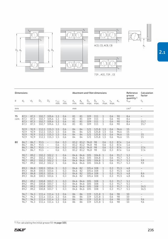
115 20 49,4 46,5 1,96 10 000 16 000 0,63 7015 ACD/P4A S H1, L 87,3 87,3 102,7 105,6 1,1 0,6 81 81 109 111 1 0,6 90 8,4 –115 20 49,4 46,5 1,96 13 000 20 000 0,53 7015 ACD/HCP4A S H1, L 87,3 87,3 102,7 105,6 1,1 0,6 81 81 109 111 1 0,6 90 8,4 –115 20 52,7 49 2,08 11 000 18 000 0,63 7015 CD/P4A S H1, L 87,3 87,3 102,7 105,6 1,1 0,6 81 81 109 111 1 0,6 90 8,4 15,7115 20 52,7 49 2,08 14 000 22 000 0,53 7015 CD/HCP4A S H1, L 87,3 87,3 102,7 105,6 1,1 0,6 81 81 109 111 1 0,6 90 8,4 15,7
130 25 68,9 58,5 2,5 9 000 15 000 1,2 7215 ACD/P4A S – 92,9 92,9 112,1 115,3 1,5 0,6 84 84 121 125,8 1,5 0,6 96,6 15 –130 25 68,9 58,5 2,5 11 000 18 000 1,05 7215 ACD/HCP4A S – 92,9 92,9 112,1 115,3 1,5 0,6 84 84 121 125,8 1,5 0,6 96,6 15 –130 25 71,5 62 2,65 10 000 17 000 1,2 7215 CD/P4A S – 92,9 92,9 112,1 115,3 1,5 0,6 84 84 121 125,8 1,5 0,6 96,6 15 15130 25 71,5 62 2,65 14 000 20 000 1,05 7215 CD/HCP4A S – 92,9 92,9 112,1 115,3 1,5 0,6 84 84 121 125,8 1,5 0,6 96,6 15 15
80 100 10 13,8 17 0,72 11 000 17 000 0,15 71816 ACD/P4 – – 80 86,7 86,7 93,5 – 0,6 0,3 83,2 83,2 96,8 98 0,6 0,3 87,4 1,6 –100 10 13,8 17 0,72 13 000 20 000 0,14 71816 ACD/HCP4 – – 86,7 86,7 93,5 – 0,6 0,3 83,2 83,2 96,8 98 0,6 0,3 87,4 1,6 –100 10 14,6 18,3 0,765 12 000 19 000 0,15 71816 CD/P4 – – 86,7 86,7 93,5 – 0,6 0,3 83,2 83,2 96,8 98 0,6 0,3 87,4 1,6 17,4100 10 14,6 18,3 0,765 15 000 22 000 0,14 71816 CD/HCP4 – – 86,7 86,7 93,5 – 0,6 0,3 83,2 83,2 96,8 98 0,6 0,3 87,4 1,6 17,4
110 16 14,8 14 0,585 14 000 22 000 0,38 71916 ACB/P4A S L 90,7 89,2 102,2 102,2 1 0,6 84,6 84,6 105 106,8 1 0,6 91,7 5,3 –110 16 14,8 14 0,585 17 000 26 000 0,35 71916 ACB/HCP4A S L 90,7 89,2 102,2 102,2 1 0,6 84,6 84,6 105 106,8 1 0,6 91,7 5,3 –110 16 15,6 14,6 0,63 16 000 24 000 0,38 71916 CB/P4A S L 90,7 89,2 102,2 102,2 1 0,6 84,6 84,6 105 106,8 1 0,6 91,7 5,3 9,9110 16 15,6 14,6 0,63 19 000 30 000 0,35 71916 CB/HCP4A S L 90,7 89,2 102,2 102,2 1 0,6 84,6 84,6 105 106,8 1 0,6 91,7 5,3 9,9
110 16 21,2 17 0,71 14 500 22 000 0,36 71916 ACE/P4A S H1, L 89,3 86,8 100,5 103,6 1 0,3 84,6 82 105,4 108 1 0,3 91,5 4,8 –110 16 21,2 17 0,71 17 500 27 000 0,31 71916 ACE/HCP4A S H1, L 89,3 86,8 100,5 103,6 1 0,3 84,6 82 105,4 108 1 0,3 91,5 4,8 –110 16 22,5 18 0,75 16 500 25 000 0,36 71916 CE/P4A S H1, L 89,3 86,8 100,5 103,6 1 0,3 84,6 82 105,4 108 1 0,3 91,5 4,8 8,6110 16 22,5 18 0,75 19 000 30 000 0,31 71916 CE/HCP4A S H1, L 89,3 86,8 100,5 103,6 1 0,3 84,6 82 105,4 108 1 0,3 91,5 4,8 8,6
110 16 34,5 36,5 1,56 9 500 16 000 0,37 71916 ACD/P4A S H1, L 89,2 89,2 100,8 103,7 1 0,3 84,6 84,6 105 108 1 0,3 91,7 5,1 –110 16 34,5 36,5 1,56 12 000 19 000 0,32 71916 ACD/HCP4A S H1, L 89,2 89,2 100,8 103,7 1 0,3 84,6 84,6 105 108 1 0,3 91,7 5,1 –110 16 36,4 39 1,66 11 000 18 000 0,37 71916 CD/P4A S H1, L 89,2 89,2 100,8 103,7 1 0,3 84,6 84,6 105 108 1 0,3 91,7 5,1 16,5110 16 36,4 39 1,66 15 000 22 000 0,32 71916 CD/HCP4A S H1, L 89,2 89,2 100,8 103,7 1 0,3 84,6 84,6 105 108 1 0,3 91,7 5,1 16,5
125 22 25,1 21,6 0,9 12 000 19 000 0,92 7016 ACB/P4A S L 96,7 94,3 111,4 111,4 1,1 0,6 86 86 119 121,8 1 0,6 98 10 –125 22 25,1 21,6 0,9 15 000 22 000 0,86 7016 ACB/HCP4A S L 96,7 94,3 111,4 111,4 1,1 0,6 86 86 119 121,8 1 0,6 98 10 –125 22 26,5 22,8 0,95 14 000 20 000 0,92 7016 CB/P4A S L 96,7 94,3 111,4 111,4 1,1 0,6 86 86 119 121,8 1 0,6 98 10 9,6125 22 26,5 22,8 0,95 17 000 26 000 0,86 7016 CB/HCP4A S L 96,7 94,3 111,4 111,4 1,1 0,6 86 86 119 121,8 1 0,6 98 10 9,6
75cont.
1) For calculating the initial grease fill † page 101
ACD, CD, ACB, CB
719 .. ACE, 719 .. CE
Db
ra
ra
dadbDa
rb
ra
ra
ra
ra
rb
dn
Principal dimensions
Basic load ratings
Fatigue load limit
Attainable speeds Mass2) Designation Available variants Dimensions Abutment and fillet dimensions Reference grease quantity1)
Calculation factorGrease
lubricationOil-air lubrica-tion2)
Sealing solu-tion1)
Direct oil-air lubrication3)dynamic static
d D B C C0 Pu d d1 d2 D1 D2 r1,2 r3,4 da db Da Db ra rb dn Gref f0min. min. min. min. max. max. max. max.
mm kN kN r/min kg – – mm mm cm3 –
235
2.1

125 22 32,5 26,5 1,12 13 700 21 000 0,86 7016 ACE/P4A S H1, L, L1 95,8 93 112,6 112,6 1,1 0,6 86 86 119 120,8 1 0,6 98,5 12 –125 22 32,5 26,5 1,12 15 500 24 000 0,77 7016 ACE/HCP4A S H1, L, L1 95,8 93 112,6 112,6 1,1 0,6 86 86 119 120,8 1 0,6 98,5 12 –125 22 33,8 28 1,18 15 000 24 000 0,86 7016 CE/P4A S H1, L, L1 95,8 93 112,6 112,6 1,1 0,6 86 86 119 120,8 1 0,6 98,5 12 9,4125 22 33,8 28 1,18 17 500 27 000 0,77 7016 CE/HCP4A S H1, L, L1 95,8 93 112,6 112,6 1,1 0,6 86 86 119 120,8 1 0,6 98,5 12 9,4
125 22 62,4 58,5 2,45 9 500 15 000 0,85 7016 ACD/P4A S H1, L 93,9 93,9 111,1 114 1,1 0,6 86 86 119 121 1 0,6 96,9 11 –125 22 62,4 58,5 2,45 12 000 18 000 0,71 7016 ACD/HCP4A S H1, L 93,9 93,9 111,1 114 1,1 0,6 86 86 119 121 1 0,6 96,9 11 –125 22 65 61 2,55 10 000 17 000 0,85 7016 CD/P4A S H1, L 93,9 93,9 111,1 114 1,1 0,6 86 86 119 121 1 0,6 96,9 11 15,5125 22 65 61 2,55 13 000 20 000 0,71 7016 CD/HCP4A S H1, L 93,9 93,9 111,1 114 1,1 0,6 86 86 119 121 1 0,6 96,9 11 15,5
140 26 81,9 72 2,9 8 500 14 000 1,45 7216 ACD/P4A S – 99,5 99,5 120,5 124,3 2 1 91 91 129 134,4 2 1 103,4 18 –140 26 81,9 72 2,9 10 000 17 000 1,25 7216 ACD/HCP4A S – 99,5 99,5 120,5 124,3 2 1 91 91 129 134,4 2 1 103,4 18 –140 26 85,2 75 3,05 9 500 16 000 1,45 7216 CD/P4A S – 99,5 99,5 120,5 124,3 2 1 91 91 129 134,4 2 1 103,4 18 15,1140 26 85,2 75 3,05 12 000 18 000 1,25 7216 CD/HCP4A S – 99,5 99,5 120,5 124,3 2 1 91 91 129 134,4 2 1 103,4 18 15,1
85 110 13 20,3 24 1,02 10 000 16 000 0,27 71817 ACD/P4 – – 85 93,2 93,2 102,1 – 1 0,3 89,6 89,6 105,4 108 1 0,3 94,1 2,7 –110 13 20,3 24 1,02 12 000 19 000 0,24 71817 ACD/HCP4 – – 93,2 93,2 102,1 – 1 0,3 89,6 89,6 105,4 108 1 0,3 94,1 2,7 –110 13 21,6 25,5 1,08 11 000 17 000 0,27 71817 CD/P4 – – 93,2 93,2 102,1 – 1 0,3 89,6 89,6 105,4 108 1 0,3 94,1 2,7 17,1110 13 21,6 25,5 1,08 14 000 20 000 0,24 71817 CD/HCP4 – – 93,2 93,2 102,1 – 1 0,3 89,6 89,6 105,4 108 1 0,3 94,1 2,7 17,1
120 18 15,3 15,3 0,64 13 000 20 000 0,57 71917 ACB/P4A S L 98,2 96,7 110,2 110,2 1,1 0,6 91 91 114 116,8 1 0,6 99,2 6,5 –120 18 15,3 15,3 0,64 16 000 24 000 0,54 71917 ACB/HCP4A S L 98,2 96,7 110,2 110,2 1,1 0,6 91 91 114 116,8 1 0,6 99,2 6,5 –120 18 16,3 16,3 0,68 15 000 22 000 0,57 71917 CB/P4A S L 98,2 96,7 110,2 110,2 1,1 0,6 91 91 114 116,8 1 0,6 99,2 6,5 10120 18 16,3 16,3 0,68 18 000 28 000 0,54 71917 CB/HCP4A S L 98,2 96,7 110,2 110,2 1,1 0,6 91 91 114 116,8 1 0,6 99,2 6,5 10
120 18 28,1 22 0,9 13 700 21 000 0,5 71917 ACE/P4A S H1, L 96 92,9 109,2 112,3 1,1 0,6 91 88,2 114 116,8 1 0,6 98,6 7 –120 18 28,1 22 0,9 16 500 25 000 0,42 71917 ACE/HCP4A S H1, L 96 92,9 109,2 112,3 1,1 0,6 91 88,2 114 116,8 1 0,6 98,6 7 –120 18 29,6 23,2 0,95 15 500 24 000 0,5 71917 CE/P4A S H1, L 96 92,9 109,2 112,3 1,1 0,6 91 88,2 114 116,8 1 0,6 98,6 7 8,4120 18 29,6 23,2 0,95 18 000 28 000 0,42 71917 CE/HCP4A S H1, L 96 92,9 109,2 112,3 1,1 0,6 91 88,2 114 116,8 1 0,6 98,6 7 8,4
120 18 43,6 45,5 1,93 9 000 15 000 0,53 71917 ACD/P4A S H1, L 95,8 95,8 109,2 112,2 1,1 0,6 91 91 114 116 1 0,6 98,6 7,2 –120 18 43,6 45,5 1,93 11 000 18 000 0,45 71917 ACD/HCP4A S H1, L 95,8 95,8 109,2 112,2 1,1 0,6 91 91 114 116 1 0,6 98,6 7,2 –120 18 46,2 48 2,04 10 000 17 000 0,53 71917 CD/P4A S H1, L 95,8 95,8 109,2 112,2 1,1 0,6 91 91 114 116 1 0,6 98,6 7,2 16,2120 18 46,2 48 2,04 14 000 20 000 0,45 71917 CD/HCP4A S H1, L 95,8 95,8 109,2 112,2 1,1 0,6 91 91 114 116 1 0,6 98,6 7,2 16,2
80cont.
1) Designation prefix S. For details, refer to Sealing solutions († page 136).2) Applicable to open bearings only.3) Designation suffix H, H1, L or L1. For details, refer to Direct oilair lubrication († page 136).
2.1 Angular contact ball bearings d 80 – 85 mm
r3r4
r1 r3
r1
r4r2
r2
d1d2
r1
r1
r3
r1
r4r2
r2r2
D1D d
B
r1
r1
r3
r1
r4r2
r2r2
D1 D2
r1
r1
r3
r1
r4r2
r2r2
D1
ACD, CD ACB, CB 719 .. ACE, 719 .. CE
70 .. ACE, 70 .. CE
S... 1)
Principal dimensions
Basic load ratings
Fatigue load limit
Attainable speeds Mass2) Designation Available variants Dimensions Abutment and fillet dimensions Reference grease quantity1)
Calculation factorGrease
lubricationOil-air lubrica-tion2)
Sealing solu-tion1)
Direct oil-air lubrication3)dynamic static
d D B C C0 Pu d d1 d2 D1 D2 r1,2 r3,4 da db Da Db ra rb dn Gref f0min. min. min. min. max. max. max. max.
mm kN kN r/min kg – – mm mm cm3 –
236

125 22 32,5 26,5 1,12 13 700 21 000 0,86 7016 ACE/P4A S H1, L, L1 95,8 93 112,6 112,6 1,1 0,6 86 86 119 120,8 1 0,6 98,5 12 –125 22 32,5 26,5 1,12 15 500 24 000 0,77 7016 ACE/HCP4A S H1, L, L1 95,8 93 112,6 112,6 1,1 0,6 86 86 119 120,8 1 0,6 98,5 12 –125 22 33,8 28 1,18 15 000 24 000 0,86 7016 CE/P4A S H1, L, L1 95,8 93 112,6 112,6 1,1 0,6 86 86 119 120,8 1 0,6 98,5 12 9,4125 22 33,8 28 1,18 17 500 27 000 0,77 7016 CE/HCP4A S H1, L, L1 95,8 93 112,6 112,6 1,1 0,6 86 86 119 120,8 1 0,6 98,5 12 9,4
125 22 62,4 58,5 2,45 9 500 15 000 0,85 7016 ACD/P4A S H1, L 93,9 93,9 111,1 114 1,1 0,6 86 86 119 121 1 0,6 96,9 11 –125 22 62,4 58,5 2,45 12 000 18 000 0,71 7016 ACD/HCP4A S H1, L 93,9 93,9 111,1 114 1,1 0,6 86 86 119 121 1 0,6 96,9 11 –125 22 65 61 2,55 10 000 17 000 0,85 7016 CD/P4A S H1, L 93,9 93,9 111,1 114 1,1 0,6 86 86 119 121 1 0,6 96,9 11 15,5125 22 65 61 2,55 13 000 20 000 0,71 7016 CD/HCP4A S H1, L 93,9 93,9 111,1 114 1,1 0,6 86 86 119 121 1 0,6 96,9 11 15,5
140 26 81,9 72 2,9 8 500 14 000 1,45 7216 ACD/P4A S – 99,5 99,5 120,5 124,3 2 1 91 91 129 134,4 2 1 103,4 18 –140 26 81,9 72 2,9 10 000 17 000 1,25 7216 ACD/HCP4A S – 99,5 99,5 120,5 124,3 2 1 91 91 129 134,4 2 1 103,4 18 –140 26 85,2 75 3,05 9 500 16 000 1,45 7216 CD/P4A S – 99,5 99,5 120,5 124,3 2 1 91 91 129 134,4 2 1 103,4 18 15,1140 26 85,2 75 3,05 12 000 18 000 1,25 7216 CD/HCP4A S – 99,5 99,5 120,5 124,3 2 1 91 91 129 134,4 2 1 103,4 18 15,1
85 110 13 20,3 24 1,02 10 000 16 000 0,27 71817 ACD/P4 – – 85 93,2 93,2 102,1 – 1 0,3 89,6 89,6 105,4 108 1 0,3 94,1 2,7 –110 13 20,3 24 1,02 12 000 19 000 0,24 71817 ACD/HCP4 – – 93,2 93,2 102,1 – 1 0,3 89,6 89,6 105,4 108 1 0,3 94,1 2,7 –110 13 21,6 25,5 1,08 11 000 17 000 0,27 71817 CD/P4 – – 93,2 93,2 102,1 – 1 0,3 89,6 89,6 105,4 108 1 0,3 94,1 2,7 17,1110 13 21,6 25,5 1,08 14 000 20 000 0,24 71817 CD/HCP4 – – 93,2 93,2 102,1 – 1 0,3 89,6 89,6 105,4 108 1 0,3 94,1 2,7 17,1
120 18 15,3 15,3 0,64 13 000 20 000 0,57 71917 ACB/P4A S L 98,2 96,7 110,2 110,2 1,1 0,6 91 91 114 116,8 1 0,6 99,2 6,5 –120 18 15,3 15,3 0,64 16 000 24 000 0,54 71917 ACB/HCP4A S L 98,2 96,7 110,2 110,2 1,1 0,6 91 91 114 116,8 1 0,6 99,2 6,5 –120 18 16,3 16,3 0,68 15 000 22 000 0,57 71917 CB/P4A S L 98,2 96,7 110,2 110,2 1,1 0,6 91 91 114 116,8 1 0,6 99,2 6,5 10120 18 16,3 16,3 0,68 18 000 28 000 0,54 71917 CB/HCP4A S L 98,2 96,7 110,2 110,2 1,1 0,6 91 91 114 116,8 1 0,6 99,2 6,5 10
120 18 28,1 22 0,9 13 700 21 000 0,5 71917 ACE/P4A S H1, L 96 92,9 109,2 112,3 1,1 0,6 91 88,2 114 116,8 1 0,6 98,6 7 –120 18 28,1 22 0,9 16 500 25 000 0,42 71917 ACE/HCP4A S H1, L 96 92,9 109,2 112,3 1,1 0,6 91 88,2 114 116,8 1 0,6 98,6 7 –120 18 29,6 23,2 0,95 15 500 24 000 0,5 71917 CE/P4A S H1, L 96 92,9 109,2 112,3 1,1 0,6 91 88,2 114 116,8 1 0,6 98,6 7 8,4120 18 29,6 23,2 0,95 18 000 28 000 0,42 71917 CE/HCP4A S H1, L 96 92,9 109,2 112,3 1,1 0,6 91 88,2 114 116,8 1 0,6 98,6 7 8,4
120 18 43,6 45,5 1,93 9 000 15 000 0,53 71917 ACD/P4A S H1, L 95,8 95,8 109,2 112,2 1,1 0,6 91 91 114 116 1 0,6 98,6 7,2 –120 18 43,6 45,5 1,93 11 000 18 000 0,45 71917 ACD/HCP4A S H1, L 95,8 95,8 109,2 112,2 1,1 0,6 91 91 114 116 1 0,6 98,6 7,2 –120 18 46,2 48 2,04 10 000 17 000 0,53 71917 CD/P4A S H1, L 95,8 95,8 109,2 112,2 1,1 0,6 91 91 114 116 1 0,6 98,6 7,2 16,2120 18 46,2 48 2,04 14 000 20 000 0,45 71917 CD/HCP4A S H1, L 95,8 95,8 109,2 112,2 1,1 0,6 91 91 114 116 1 0,6 98,6 7,2 16,2
80cont.
1) For calculating the initial grease fill † page 101
ACD, CD, ACB, CB, 70 .. ACE, 70 .. CE
719 .. ACE, 719 .. CE
Db
ra
ra
dadbDa
rb
ra
ra
ra
ra
rb
dn
Principal dimensions
Basic load ratings
Fatigue load limit
Attainable speeds Mass2) Designation Available variants Dimensions Abutment and fillet dimensions Reference grease quantity1)
Calculation factorGrease
lubricationOil-air lubrica-tion2)
Sealing solu-tion1)
Direct oil-air lubrication3)dynamic static
d D B C C0 Pu d d1 d2 D1 D2 r1,2 r3,4 da db Da Db ra rb dn Gref f0min. min. min. min. max. max. max. max.
mm kN kN r/min kg – – mm mm cm3 –
237
2.1

130 22 25,1 22,4 0,915 12 000 18 000 0,96 7017 ACB/P4A S L 101,7 99,3 116,4 116,4 1,1 0,6 91 91 124 126,8 1 0,6 103 11 –130 22 25,1 22,4 0,915 14 000 22 000 0,9 7017 ACB/HCP4A S L 101,7 99,3 116,4 116,4 1,1 0,6 91 91 124 126,8 1 0,6 103 11 –130 22 27 23,6 0,965 13 000 20 000 0,96 7017 CB/P4A S L 101,7 99,3 116,4 116,4 1,1 0,6 91 91 124 126,8 1 0,6 103 11 9,6130 22 27 23,6 0,965 16 000 24 000 0,9 7017 CB/HCP4A S L 101,7 99,3 116,4 116,4 1,1 0,6 91 91 124 126,8 1 0,6 103 11 9,6
130 22 32,5 28 1,14 13 000 20 000 0,9 7017 ACE/P4A S H1, L, L1 100,8 98 117,6 117,6 1,1 0,6 91 91 124 125,8 1 0,6 103,5 12 –130 22 32,5 28 1,14 15 000 23 000 0,81 7017 ACE/HCP4A S H1, L, L1 100,8 98 117,6 117,6 1,1 0,6 91 91 124 125,8 1 0,6 103,5 12 –130 22 34,5 29 1,2 14 000 22 000 0,9 7017 CE/P4A S H1, L, L1 100,8 98 117,6 117,6 1,1 0,6 91 91 124 125,8 1 0,6 103,5 12 9,5130 22 34,5 29 1,2 16 500 26 000 0,81 7017 CE/HCP4A S H1, L, L1 100,8 98 117,6 117,6 1,1 0,6 91 91 124 125,8 1 0,6 103,5 12 9,5
130 22 63,7 62 2,5 9 000 14 000 0,9 7017 ACD/P4A S H1, L 98,9 98,9 116,1 119,1 1,1 0,6 91 91 124 126 1 0,6 101,9 12 –130 22 63,7 62 2,5 11 000 17 000 0,75 7017 ACD/HCP4A S H1, L 98,9 98,9 116,1 119,1 1,1 0,6 91 91 124 126 1 0,6 101,9 12 –130 22 67,6 65,5 2,65 10 000 16 000 0,9 7017 CD/P4A S H1, L 98,9 98,9 116,1 119,1 1,1 0,6 91 91 124 126 1 0,6 101,9 12 15,7130 22 67,6 65,5 2,65 12 000 19 000 0,75 7017 CD/HCP4A S H1, L 98,9 98,9 116,1 119,1 1,1 0,6 91 91 124 126 1 0,6 101,9 12 15,7
150 28 95,6 85 3,35 8 000 13 000 1,85 7217 ACD/P4A – – 106,5 106,5 129,5 – 2 1 96 96 139 144,4 2 1 111,5 22 –150 28 95,6 85 3,35 9 500 16 000 1,55 7217 ACD/HCP4A – – 106,5 106,5 129,5 – 2 1 96 96 139 144,4 2 1 111,5 22 –150 28 99,5 88 3,45 9 000 15 000 1,85 7217 CD/P4A – – 106,5 106,5 129,5 – 2 1 96 96 139 144,4 2 1 111,5 22 14,9150 28 99,5 88 3,45 11 000 17 000 1,55 7217 CD/HCP4A – – 106,5 106,5 129,5 – 2 1 96 96 139 144,4 2 1 111,5 22 14,9
90 115 13 20,3 25 1,04 10 000 15 000 0,28 71818 ACD/P4 – – 90 98,2 98,2 107,1 – 1 0,3 94,6 94,6 110,4 113 1 0,3 99,1 2,9 –115 13 20,3 25 1,04 12 000 18 000 0,25 71818 ACD/HCP4 – – 98,2 98,2 107,1 – 1 0,3 94,6 94,6 110,4 113 1 0,3 99,1 2,9 –115 13 21,6 26,5 1,1 11 000 17 000 0,28 71818 CD/P4 – – 98,2 98,2 107,1 – 1 0,3 94,6 94,6 110,4 113 1 0,3 99,1 2,9 17,2115 13 21,6 26,5 1,1 13 000 20 000 0,25 71818 CD/HCP4 – – 98,2 98,2 107,1 – 1 0,3 94,6 94,6 110,4 113 1 0,3 99,1 2,9 17,2
125 18 16,8 16,6 0,68 12 000 19 000 0,59 71918 ACB/P4A S L 103 101,4 115 115 1,1 0,6 96 96 119 121,8 1 0,6 103,9 7,4 –125 18 16,8 16,6 0,68 15 000 22 000 0,56 71918 ACB/HCP4A S L 103 101,4 115 115 1,1 0,6 96 96 119 121,8 1 0,6 103,9 7,4 –125 18 17,8 17,6 0,72 14 000 22 000 0,59 71918 CB/P4A S L 103 101,4 115 115 1,1 0,6 96 96 119 121,8 1 0,6 103,9 7,4 10125 18 17,8 17,6 0,72 16 000 26 000 0,56 71918 CB/HCP4A S L 103 101,4 115 115 1,1 0,6 96 96 119 121,8 1 0,6 103,9 7,4 10
125 18 28,6 23,2 0,915 13 000 20 000 0,54 71918 ACE/P4A S H1, L 101 97,9 114,2 117,3 1,1 0,6 96 93,2 119 121,8 1 0,6 103,5 7 –125 18 28,6 23,2 0,915 15 500 24 000 0,46 71918 ACE/HCP4A S H1, L 101 97,9 114,2 117,3 1,1 0,6 96 93,2 119 121,8 1 0,6 103,5 7 –125 18 30,2 24,5 0,965 14 500 22 000 0,54 71918 CE/P4A S H1, L 101 97,9 114,2 117,3 1,1 0,6 96 93,2 119 121,8 1 0,6 103,5 7 8,5125 18 30,2 24,5 0,965 17 000 27 000 0,46 71918 CE/HCP4A S H1, L 101 97,9 114,2 117,3 1,1 0,6 96 93,2 119 121,8 1 0,6 103,5 7 8,5
85cont.
1) Designation prefix S. For details, refer to Sealing solutions († page 136).2) Applicable to open bearings only.3) Designation suffix H, H1, L or L1. For details, refer to Direct oilair lubrication († page 136).
2.1 Angular contact ball bearings d 85 – 90 mm
r3r4
r1 r3
r1
r4r2
r2
d1d2
r1
r1
r3
r1
r4r2
r2r2
D1D d
B
r1
r1
r3
r1
r4r2
r2r2
D1 D2
r1
r1
r3
r1
r4r2
r2r2
D1
ACD, CD ACB, CB 719 .. ACE, 719 .. CE
70 .. ACE, 70 .. CE
S... 1)
Principal dimensions
Basic load ratings
Fatigue load limit
Attainable speeds Mass2) Designation Available variants Dimensions Abutment and fillet dimensions Reference grease quantity1)
Calculation factorGrease
lubricationOil-air lubrica-tion2)
Sealing solu-tion1)
Direct oil-air lubrication3)dynamic static
d D B C C0 Pu d d1 d2 D1 D2 r1,2 r3,4 da db Da Db ra rb dn Gref f0min. min. min. min. max. max. max. max.
mm kN kN r/min kg – – mm mm cm3 –
238

130 22 25,1 22,4 0,915 12 000 18 000 0,96 7017 ACB/P4A S L 101,7 99,3 116,4 116,4 1,1 0,6 91 91 124 126,8 1 0,6 103 11 –130 22 25,1 22,4 0,915 14 000 22 000 0,9 7017 ACB/HCP4A S L 101,7 99,3 116,4 116,4 1,1 0,6 91 91 124 126,8 1 0,6 103 11 –130 22 27 23,6 0,965 13 000 20 000 0,96 7017 CB/P4A S L 101,7 99,3 116,4 116,4 1,1 0,6 91 91 124 126,8 1 0,6 103 11 9,6130 22 27 23,6 0,965 16 000 24 000 0,9 7017 CB/HCP4A S L 101,7 99,3 116,4 116,4 1,1 0,6 91 91 124 126,8 1 0,6 103 11 9,6
130 22 32,5 28 1,14 13 000 20 000 0,9 7017 ACE/P4A S H1, L, L1 100,8 98 117,6 117,6 1,1 0,6 91 91 124 125,8 1 0,6 103,5 12 –130 22 32,5 28 1,14 15 000 23 000 0,81 7017 ACE/HCP4A S H1, L, L1 100,8 98 117,6 117,6 1,1 0,6 91 91 124 125,8 1 0,6 103,5 12 –130 22 34,5 29 1,2 14 000 22 000 0,9 7017 CE/P4A S H1, L, L1 100,8 98 117,6 117,6 1,1 0,6 91 91 124 125,8 1 0,6 103,5 12 9,5130 22 34,5 29 1,2 16 500 26 000 0,81 7017 CE/HCP4A S H1, L, L1 100,8 98 117,6 117,6 1,1 0,6 91 91 124 125,8 1 0,6 103,5 12 9,5
130 22 63,7 62 2,5 9 000 14 000 0,9 7017 ACD/P4A S H1, L 98,9 98,9 116,1 119,1 1,1 0,6 91 91 124 126 1 0,6 101,9 12 –130 22 63,7 62 2,5 11 000 17 000 0,75 7017 ACD/HCP4A S H1, L 98,9 98,9 116,1 119,1 1,1 0,6 91 91 124 126 1 0,6 101,9 12 –130 22 67,6 65,5 2,65 10 000 16 000 0,9 7017 CD/P4A S H1, L 98,9 98,9 116,1 119,1 1,1 0,6 91 91 124 126 1 0,6 101,9 12 15,7130 22 67,6 65,5 2,65 12 000 19 000 0,75 7017 CD/HCP4A S H1, L 98,9 98,9 116,1 119,1 1,1 0,6 91 91 124 126 1 0,6 101,9 12 15,7
150 28 95,6 85 3,35 8 000 13 000 1,85 7217 ACD/P4A – – 106,5 106,5 129,5 – 2 1 96 96 139 144,4 2 1 111,5 22 –150 28 95,6 85 3,35 9 500 16 000 1,55 7217 ACD/HCP4A – – 106,5 106,5 129,5 – 2 1 96 96 139 144,4 2 1 111,5 22 –150 28 99,5 88 3,45 9 000 15 000 1,85 7217 CD/P4A – – 106,5 106,5 129,5 – 2 1 96 96 139 144,4 2 1 111,5 22 14,9150 28 99,5 88 3,45 11 000 17 000 1,55 7217 CD/HCP4A – – 106,5 106,5 129,5 – 2 1 96 96 139 144,4 2 1 111,5 22 14,9
90 115 13 20,3 25 1,04 10 000 15 000 0,28 71818 ACD/P4 – – 90 98,2 98,2 107,1 – 1 0,3 94,6 94,6 110,4 113 1 0,3 99,1 2,9 –115 13 20,3 25 1,04 12 000 18 000 0,25 71818 ACD/HCP4 – – 98,2 98,2 107,1 – 1 0,3 94,6 94,6 110,4 113 1 0,3 99,1 2,9 –115 13 21,6 26,5 1,1 11 000 17 000 0,28 71818 CD/P4 – – 98,2 98,2 107,1 – 1 0,3 94,6 94,6 110,4 113 1 0,3 99,1 2,9 17,2115 13 21,6 26,5 1,1 13 000 20 000 0,25 71818 CD/HCP4 – – 98,2 98,2 107,1 – 1 0,3 94,6 94,6 110,4 113 1 0,3 99,1 2,9 17,2
125 18 16,8 16,6 0,68 12 000 19 000 0,59 71918 ACB/P4A S L 103 101,4 115 115 1,1 0,6 96 96 119 121,8 1 0,6 103,9 7,4 –125 18 16,8 16,6 0,68 15 000 22 000 0,56 71918 ACB/HCP4A S L 103 101,4 115 115 1,1 0,6 96 96 119 121,8 1 0,6 103,9 7,4 –125 18 17,8 17,6 0,72 14 000 22 000 0,59 71918 CB/P4A S L 103 101,4 115 115 1,1 0,6 96 96 119 121,8 1 0,6 103,9 7,4 10125 18 17,8 17,6 0,72 16 000 26 000 0,56 71918 CB/HCP4A S L 103 101,4 115 115 1,1 0,6 96 96 119 121,8 1 0,6 103,9 7,4 10
125 18 28,6 23,2 0,915 13 000 20 000 0,54 71918 ACE/P4A S H1, L 101 97,9 114,2 117,3 1,1 0,6 96 93,2 119 121,8 1 0,6 103,5 7 –125 18 28,6 23,2 0,915 15 500 24 000 0,46 71918 ACE/HCP4A S H1, L 101 97,9 114,2 117,3 1,1 0,6 96 93,2 119 121,8 1 0,6 103,5 7 –125 18 30,2 24,5 0,965 14 500 22 000 0,54 71918 CE/P4A S H1, L 101 97,9 114,2 117,3 1,1 0,6 96 93,2 119 121,8 1 0,6 103,5 7 8,5125 18 30,2 24,5 0,965 17 000 27 000 0,46 71918 CE/HCP4A S H1, L 101 97,9 114,2 117,3 1,1 0,6 96 93,2 119 121,8 1 0,6 103,5 7 8,5
85cont.
1) For calculating the initial grease fill † page 101
ACD, CD, ACB, CB, 70 .. ACE, 70 .. CE
719 .. ACE, 719 .. CE
Db
ra
ra
dadbDa
rb
ra
ra
ra
ra
rb
dn
Principal dimensions
Basic load ratings
Fatigue load limit
Attainable speeds Mass2) Designation Available variants Dimensions Abutment and fillet dimensions Reference grease quantity1)
Calculation factorGrease
lubricationOil-air lubrica-tion2)
Sealing solu-tion1)
Direct oil-air lubrication3)dynamic static
d D B C C0 Pu d d1 d2 D1 D2 r1,2 r3,4 da db Da Db ra rb dn Gref f0min. min. min. min. max. max. max. max.
mm kN kN r/min kg – – mm mm cm3 –
239
2.1

125 18 44,2 48 1,96 8 500 14 000 0,55 71918 ACD/P4A S H1, L 100,8 100,8 114,2 117,2 1,1 0,6 96 96 119 121 1 0,6 103,3 7,5 –125 18 44,2 48 1,96 10 000 17 000 0,47 71918 ACD/HCP4A S H1, L 100,8 100,8 114,2 117,2 1,1 0,6 96 96 119 121 1 0,6 103,3 7,5 –125 18 47,5 51 2,08 9 500 16 000 0,55 71918 CD/P4A S H1, L 100,8 100,8 114,2 117,2 1,1 0,6 96 96 119 121 1 0,6 103,3 7,5 16,3125 18 47,5 51 2,08 13 000 19 000 0,47 71918 CD/HCP4A S H1, L 100,8 100,8 114,2 117,2 1,1 0,6 96 96 119 121 1 0,6 103,3 7,5 16,3
140 24 27 23,6 0,93 11 000 17 000 1,25 7018 ACB/P4A S L 108,7 106,1 125 125 1,5 1 97 97 133 135,4 1,5 1 110 14 –140 24 27 23,6 0,93 13 000 20 000 1,2 7018 ACB/HCP4A S L 108,7 106,1 125 125 1,5 1 97 97 133 135,4 1,5 1 110 14 –140 24 29,1 25 0,98 12 000 19 000 1,25 7018 CB/P4A S L 108,7 106,1 125 125 1,5 1 97 97 133 135,4 1,5 1 110 14 9,7140 24 29,1 25 0,98 15 000 24 000 1,2 7018 CB/HCP4A S L 108,7 106,1 125 125 1,5 1 97 97 133 135,4 1,5 1 110 14 9,7
140 24 33,8 30 1,2 12 000 19 000 1,2 7018 ACE/P4A S H1, L, L1 108,3 105,5 125,2 125,2 1,5 1 97 97 133 134,4 1,5 1 111 14 –140 24 33,8 30 1,2 14 000 22 000 1,1 7018 ACE/HCP4A S H1, L, L1 108,3 105,5 125,2 125,2 1,5 1 97 97 133 134,4 1,5 1 111 14 –140 24 35,8 32 1,27 13 300 21 000 1,2 7018 CE/P4A S H1, L, L1 108,3 105,5 125,2 125,2 1,5 1 97 97 133 134,4 1,5 1 111 14 9,6140 24 35,8 32 1,27 15 500 24 000 1,1 7018 CE/HCP4A S H1, L, L1 108,3 105,5 125,2 125,2 1,5 1 97 97 133 134,4 1,5 1 111 14 9,6
140 24 74,1 72 2,85 8 500 13 000 1,15 7018 ACD/P4A S H1, L 105,4 105,4 124,6 128,3 1,5 1 97 97 133 136 1,5 1 108,7 15 –140 24 74,1 72 2,85 10 000 16 000 1 7018 ACD/HCP4A S H1, L 105,4 105,4 124,6 128,3 1,5 1 97 97 133 136 1,5 1 108,7 15 –140 24 79,3 76,5 3 9 000 15 000 1,15 7018 CD/P4A S H1, L 105,4 105,4 124,6 128,3 1,5 1 97 97 133 136 1,5 1 108,7 15 15,6140 24 79,3 76,5 3 11 000 18 000 1 7018 CD/HCP4A S H1, L 105,4 105,4 124,6 128,3 1,5 1 97 97 133 136 1,5 1 108,7 15 15,6
160 30 121 106 4,05 7 500 12 000 2,25 7218 ACD/P4A – – 111,6 111,6 138,4 – 2 1 101 101 149 154,4 2 1 117,5 28 –160 30 121 106 4,05 9 000 15 000 1,85 7218 ACD/HCP4A – – 111,6 111,6 138,4 – 2 1 101 101 149 154,4 2 1 117,5 28 –160 30 127 112 4,25 8 500 14 000 2,25 7218 CD/P4A – – 111,6 111,6 138,4 – 2 1 101 101 149 154,4 2 1 117,5 28 14,6160 30 127 112 4,25 10 000 16 000 1,85 7218 CD/HCP4A – – 111,6 111,6 138,4 – 2 1 101 101 149 154,4 2 1 117,5 28 14,6
95 120 13 20,8 25,5 1,06 9 500 14 000 0,29 71819 ACD/P4 – – 95 103,2 103,2 112,1 – 1 0,3 99,6 99,6 115,4 118 1 0,3 104,1 3,1 –120 13 20,8 25,5 1,06 11 000 17 000 0,26 71819 ACD/HCP4 – – 103,2 103,2 112,1 – 1 0,3 99,6 99,6 115,4 118 1 0,3 104,1 3,1 –120 13 22,1 27,5 1,12 10 000 16 000 0,29 71819 CD/P4 – – 103,2 103,2 112,1 – 1 0,3 99,6 99,6 115,4 118 1 0,3 104,1 3,1 17,3120 13 22,1 27,5 1,12 12 000 19 000 0,26 71819 CD/HCP4 – – 103,2 103,2 112,1 – 1 0,3 99,6 99,6 115,4 118 1 0,3 104,1 3,1 17,3
130 18 17,2 17,6 0,71 12 000 18 000 0,61 71919 ACB/P4A S L 107,9 106,4 120,7 120,7 1,1 0,6 101 101 124 126,8 1 0,6 109 7,5 –130 18 17,2 17,6 0,71 14 000 22 000 0,58 71919 ACB/HCP4A S L 107,9 106,4 120,7 120,7 1,1 0,6 101 101 124 126,8 1 0,6 109 7,5 –130 18 18,2 18,6 0,75 13 000 20 000 0,61 71919 CB/P4A S L 107,9 106,4 120,7 120,7 1,1 0,6 101 101 124 126,8 1 0,6 109 7,5 10130 18 18,2 18,6 0,75 16 000 24 000 0,58 71919 CB/HCP4A S L 107,9 106,4 120,7 120,7 1,1 0,6 101 101 124 126,8 1 0,6 109 7,5 10
90cont.
1) Designation prefix S. For details, refer to Sealing solutions († page 136).2) Applicable to open bearings only.3) Designation suffix H, H1, L or L1. For details, refer to Direct oilair lubrication († page 136).
2.1 Angular contact ball bearings d 90 – 95 mm
d1d2
r1
r1
r3
r1
r4r2
r2r2
D1D d
B
r1
r1
r3
r1
r4r2
r2r2
D1 D2
r1
r1
r3
r1
r4r2
r2r2
D1
ACD, CD ACB, CB 70 .. ACE, 70 .. CE
S... 1)
Principal dimensions
Basic load ratings
Fatigue load limit
Attainable speeds Mass2) Designation Available variants Dimensions Abutment and fillet dimensions Reference grease quantity1)
Calculation factorGrease
lubricationOil-air lubrica-tion2)
Sealing solu-tion1)
Direct oil-air lubrication3)dynamic static
d D B C C0 Pu d d1 d2 D1 D2 r1,2 r3,4 da db Da Db ra rb dn Gref f0min. min. min. min. max. max. max. max.
mm kN kN r/min kg – – mm mm cm3 –
240

125 18 44,2 48 1,96 8 500 14 000 0,55 71918 ACD/P4A S H1, L 100,8 100,8 114,2 117,2 1,1 0,6 96 96 119 121 1 0,6 103,3 7,5 –125 18 44,2 48 1,96 10 000 17 000 0,47 71918 ACD/HCP4A S H1, L 100,8 100,8 114,2 117,2 1,1 0,6 96 96 119 121 1 0,6 103,3 7,5 –125 18 47,5 51 2,08 9 500 16 000 0,55 71918 CD/P4A S H1, L 100,8 100,8 114,2 117,2 1,1 0,6 96 96 119 121 1 0,6 103,3 7,5 16,3125 18 47,5 51 2,08 13 000 19 000 0,47 71918 CD/HCP4A S H1, L 100,8 100,8 114,2 117,2 1,1 0,6 96 96 119 121 1 0,6 103,3 7,5 16,3
140 24 27 23,6 0,93 11 000 17 000 1,25 7018 ACB/P4A S L 108,7 106,1 125 125 1,5 1 97 97 133 135,4 1,5 1 110 14 –140 24 27 23,6 0,93 13 000 20 000 1,2 7018 ACB/HCP4A S L 108,7 106,1 125 125 1,5 1 97 97 133 135,4 1,5 1 110 14 –140 24 29,1 25 0,98 12 000 19 000 1,25 7018 CB/P4A S L 108,7 106,1 125 125 1,5 1 97 97 133 135,4 1,5 1 110 14 9,7140 24 29,1 25 0,98 15 000 24 000 1,2 7018 CB/HCP4A S L 108,7 106,1 125 125 1,5 1 97 97 133 135,4 1,5 1 110 14 9,7
140 24 33,8 30 1,2 12 000 19 000 1,2 7018 ACE/P4A S H1, L, L1 108,3 105,5 125,2 125,2 1,5 1 97 97 133 134,4 1,5 1 111 14 –140 24 33,8 30 1,2 14 000 22 000 1,1 7018 ACE/HCP4A S H1, L, L1 108,3 105,5 125,2 125,2 1,5 1 97 97 133 134,4 1,5 1 111 14 –140 24 35,8 32 1,27 13 300 21 000 1,2 7018 CE/P4A S H1, L, L1 108,3 105,5 125,2 125,2 1,5 1 97 97 133 134,4 1,5 1 111 14 9,6140 24 35,8 32 1,27 15 500 24 000 1,1 7018 CE/HCP4A S H1, L, L1 108,3 105,5 125,2 125,2 1,5 1 97 97 133 134,4 1,5 1 111 14 9,6
140 24 74,1 72 2,85 8 500 13 000 1,15 7018 ACD/P4A S H1, L 105,4 105,4 124,6 128,3 1,5 1 97 97 133 136 1,5 1 108,7 15 –140 24 74,1 72 2,85 10 000 16 000 1 7018 ACD/HCP4A S H1, L 105,4 105,4 124,6 128,3 1,5 1 97 97 133 136 1,5 1 108,7 15 –140 24 79,3 76,5 3 9 000 15 000 1,15 7018 CD/P4A S H1, L 105,4 105,4 124,6 128,3 1,5 1 97 97 133 136 1,5 1 108,7 15 15,6140 24 79,3 76,5 3 11 000 18 000 1 7018 CD/HCP4A S H1, L 105,4 105,4 124,6 128,3 1,5 1 97 97 133 136 1,5 1 108,7 15 15,6
160 30 121 106 4,05 7 500 12 000 2,25 7218 ACD/P4A – – 111,6 111,6 138,4 – 2 1 101 101 149 154,4 2 1 117,5 28 –160 30 121 106 4,05 9 000 15 000 1,85 7218 ACD/HCP4A – – 111,6 111,6 138,4 – 2 1 101 101 149 154,4 2 1 117,5 28 –160 30 127 112 4,25 8 500 14 000 2,25 7218 CD/P4A – – 111,6 111,6 138,4 – 2 1 101 101 149 154,4 2 1 117,5 28 14,6160 30 127 112 4,25 10 000 16 000 1,85 7218 CD/HCP4A – – 111,6 111,6 138,4 – 2 1 101 101 149 154,4 2 1 117,5 28 14,6
95 120 13 20,8 25,5 1,06 9 500 14 000 0,29 71819 ACD/P4 – – 95 103,2 103,2 112,1 – 1 0,3 99,6 99,6 115,4 118 1 0,3 104,1 3,1 –120 13 20,8 25,5 1,06 11 000 17 000 0,26 71819 ACD/HCP4 – – 103,2 103,2 112,1 – 1 0,3 99,6 99,6 115,4 118 1 0,3 104,1 3,1 –120 13 22,1 27,5 1,12 10 000 16 000 0,29 71819 CD/P4 – – 103,2 103,2 112,1 – 1 0,3 99,6 99,6 115,4 118 1 0,3 104,1 3,1 17,3120 13 22,1 27,5 1,12 12 000 19 000 0,26 71819 CD/HCP4 – – 103,2 103,2 112,1 – 1 0,3 99,6 99,6 115,4 118 1 0,3 104,1 3,1 17,3
130 18 17,2 17,6 0,71 12 000 18 000 0,61 71919 ACB/P4A S L 107,9 106,4 120,7 120,7 1,1 0,6 101 101 124 126,8 1 0,6 109 7,5 –130 18 17,2 17,6 0,71 14 000 22 000 0,58 71919 ACB/HCP4A S L 107,9 106,4 120,7 120,7 1,1 0,6 101 101 124 126,8 1 0,6 109 7,5 –130 18 18,2 18,6 0,75 13 000 20 000 0,61 71919 CB/P4A S L 107,9 106,4 120,7 120,7 1,1 0,6 101 101 124 126,8 1 0,6 109 7,5 10130 18 18,2 18,6 0,75 16 000 24 000 0,58 71919 CB/HCP4A S L 107,9 106,4 120,7 120,7 1,1 0,6 101 101 124 126,8 1 0,6 109 7,5 10
90cont.
1) For calculating the initial grease fill † page 101
Db
ra
ra
dadbDa
rb
ra
ra
ra
dn
Principal dimensions
Basic load ratings
Fatigue load limit
Attainable speeds Mass2) Designation Available variants Dimensions Abutment and fillet dimensions Reference grease quantity1)
Calculation factorGrease
lubricationOil-air lubrica-tion2)
Sealing solu-tion1)
Direct oil-air lubrication3)dynamic static
d D B C C0 Pu d d1 d2 D1 D2 r1,2 r3,4 da db Da Db ra rb dn Gref f0min. min. min. min. max. max. max. max.
mm kN kN r/min kg – – mm mm cm3 –
241
2.1

130 18 29,1 24 0,93 12 300 19 000 0,56 71919 ACE/P4A S H1, L 106 102,9 119,2 122,6 1,1 0,6 101 98,2 124 126,8 1 0,6 108,5 7,3 –130 18 29,1 24 0,93 15 000 23 000 0,48 71919 ACE/HCP4A S H1, L 106 102,9 119,2 122,6 1,1 0,6 101 98,2 124 126,8 1 0,6 108,5 7,3 –130 18 30,7 25,5 0,98 14 000 21 000 0,56 71919 CE/P4A S H1, L 106 102,9 119,2 122,6 1,1 0,6 101 98,2 124 126,8 1 0,6 108,5 7,3 8,6130 18 30,7 25,5 0,98 16 000 25 000 0,48 71919 CE/HCP4A S H1, L 106 102,9 119,2 122,6 1,1 0,6 101 98,2 124 126,8 1 0,6 108,5 7,3 8,6
130 18 46,2 52 2,08 8 500 14 000 0,58 71919 ACD/P4A S H1, L 105,8 105,8 119,2 122,2 1,1 0,6 101 101 124 126 1 0,6 108,6 7,8 –130 18 46,2 52 2,08 9 500 16 000 0,5 71919 ACD/HCP4A S H1, L 105,8 105,8 119,2 122,2 1,1 0,6 101 101 124 126 1 0,6 108,6 7,8 –130 18 49,4 55 2,2 9 000 15 000 0,58 71919 CD/P4A S H1, L 105,8 105,8 119,2 122,2 1,1 0,6 101 101 124 126 1 0,6 108,6 7,8 16,4130 18 49,4 55 2,2 12 000 18 000 0,5 71919 CD/HCP4A S H1, L 105,8 105,8 119,2 122,2 1,1 0,6 101 101 124 126 1 0,6 108,6 7,8 16,4
145 24 27,6 24,5 0,95 11 000 16 000 1,3 7019 ACB/P4A S L 113,7 111,2 130 130 1,5 1 102 102 138 140,4 1,5 1 115 15 –145 24 27,6 24,5 0,95 13 000 19 000 1,25 7019 ACB/HCP4A S L 113,7 111,2 130 130 1,5 1 102 102 138 140,4 1,5 1 115 15 –145 24 29,6 26 1 12 000 18 000 1,3 7019 CB/P4A S L 113,7 111,2 130 130 1,5 1 102 102 138 140,4 1,5 1 115 15 9,7145 24 29,6 26 1 14 000 22 000 1,25 7019 CB/HCP4A S L 113,7 111,2 130 130 1,5 1 102 102 138 140,4 1,5 1 115 15 9,7
145 24 41,6 36 1,4 11 500 18 000 1,2 7019 ACE/P4A S H1, L, L1 112,4 109,2 131 131 1,5 1 102 102 138 139,4 1,5 1 115,4 17 –145 24 41,6 36 1,4 13 300 20 500 1,1 7019 ACE/HCP4A S H1, L, L1 112,4 109,2 131 131 1,5 1 102 102 138 139,4 1,5 1 115,4 17 –145 24 44,2 38 1,46 12 700 20 000 1,2 7019 CE/P4A S H1, L, L1 112,4 109,2 131 131 1,5 1 102 102 138 139,4 1,5 1 115,4 17 9,4145 24 44,2 38 1,46 15 000 23 000 1,1 7019 CE/HCP4A S H1, L, L1 112,4 109,2 131 131 1,5 1 102 102 138 139,4 1,5 1 115,4 17 9,4
145 24 76,1 76,5 2,9 8 000 13 000 1,2 7019 ACD/P4A S H1, L 110,4 110,4 129,6 133,3 1,5 1 102 102 138 141 1,5 1 113,7 16 –145 24 76,1 76,5 2,9 10 000 16 000 1 7019 ACD/HCP4A S H1, L 110,4 110,4 129,6 133,3 1,5 1 102 102 138 141 1,5 1 113,7 16 –145 24 81,9 80 3,1 8 500 14 000 1,2 7019 CD/P4A S H1, L 110,4 110,4 129,6 133,3 1,5 1 102 102 138 141 1,5 1 113,7 16 15,7145 24 81,9 80 3,1 11 000 17 000 1 7019 CD/HCP4A S H1, L 110,4 110,4 129,6 133,3 1,5 1 102 102 138 141 1,5 1 113,7 16 15,7
170 32 133 114 4,25 7 500 12 000 2,7 7219 ACD/P4A – – 118,1 118,1 146,9 – 2,1 1,1 107 107 158 163 2 1 124,4 34 –170 32 133 114 4,25 8 500 14 000 2,2 7219 ACD/HCP4A – – 118,1 118,1 146,9 – 2,1 1,1 107 107 158 163 2 1 124,4 34 –170 32 138 120 4,4 8 000 13 000 2,7 7219 CD/P4A – – 118,1 118,1 146,9 – 2,1 1,1 107 107 158 163 2 1 124,4 34 14,6170 32 138 120 4,4 9 500 15 000 2,2 7219 CD/HCP4A – – 118,1 118,1 146,9 – 2,1 1,1 107 107 158 163 2 1 124,4 34 14,6
100 125 13 21,2 27,5 1,1 8 500 13 000 0,31 71820 ACD/P4 – – 100 108,2 108,2 117 – 1 0,3 104,6 104,6 120,4 123 1 0,3 109,1 3,2 –125 13 21,2 27,5 1,1 10 000 15 000 0,28 71820 ACD/HCP4 – – 108,2 108,2 117 – 1 0,3 104,6 104,6 120,4 123 1 0,3 109,1 3,2 –125 13 22,5 29 1,16 9 000 14 000 0,31 71820 CD/P4 – – 108,2 108,2 117 – 1 0,3 104,6 104,6 120,4 123 1 0,3 109,1 3,2 17,4125 13 22,5 29 1,16 11 000 17 000 0,28 71820 CD/HCP4 – – 108,2 108,2 117 – 1 0,3 104,6 104,6 120,4 123 1 0,3 109,1 3,2 17,4
95cont.
1) Designation prefix S. For details, refer to Sealing solutions († page 136).2) Applicable to open bearings only.3) Designation suffix H, H1, L or L1. For details, refer to Direct oilair lubrication († page 136).
2.1 Angular contact ball bearings d 95 – 100 mm
r3r4
r1 r3
r1
r4r2
r2
d1d2
r1
r1
r3
r1
r4r2
r2r2
D1D d
B
r1
r1
r3
r1
r4r2
r2r2
D1 D2
r1
r1
r3
r1
r4r2
r2r2
D1
ACD, CD ACB, CB 719 .. ACE, 719 .. CE
70 .. ACE, 70 .. CE
S... 1)
Principal dimensions
Basic load ratings
Fatigue load limit
Attainable speeds Mass2) Designation Available variants Dimensions Abutment and fillet dimensions Reference grease quantity1)
Calculation factorGrease
lubricationOil-air lubrica-tion2)
Sealing solu-tion1)
Direct oil-air lubrication3)dynamic static
d D B C C0 Pu d d1 d2 D1 D2 r1,2 r3,4 da db Da Db ra rb dn Gref f0min. min. min. min. max. max. max. max.
mm kN kN r/min kg – – mm mm cm3 –
242

130 18 29,1 24 0,93 12 300 19 000 0,56 71919 ACE/P4A S H1, L 106 102,9 119,2 122,6 1,1 0,6 101 98,2 124 126,8 1 0,6 108,5 7,3 –130 18 29,1 24 0,93 15 000 23 000 0,48 71919 ACE/HCP4A S H1, L 106 102,9 119,2 122,6 1,1 0,6 101 98,2 124 126,8 1 0,6 108,5 7,3 –130 18 30,7 25,5 0,98 14 000 21 000 0,56 71919 CE/P4A S H1, L 106 102,9 119,2 122,6 1,1 0,6 101 98,2 124 126,8 1 0,6 108,5 7,3 8,6130 18 30,7 25,5 0,98 16 000 25 000 0,48 71919 CE/HCP4A S H1, L 106 102,9 119,2 122,6 1,1 0,6 101 98,2 124 126,8 1 0,6 108,5 7,3 8,6
130 18 46,2 52 2,08 8 500 14 000 0,58 71919 ACD/P4A S H1, L 105,8 105,8 119,2 122,2 1,1 0,6 101 101 124 126 1 0,6 108,6 7,8 –130 18 46,2 52 2,08 9 500 16 000 0,5 71919 ACD/HCP4A S H1, L 105,8 105,8 119,2 122,2 1,1 0,6 101 101 124 126 1 0,6 108,6 7,8 –130 18 49,4 55 2,2 9 000 15 000 0,58 71919 CD/P4A S H1, L 105,8 105,8 119,2 122,2 1,1 0,6 101 101 124 126 1 0,6 108,6 7,8 16,4130 18 49,4 55 2,2 12 000 18 000 0,5 71919 CD/HCP4A S H1, L 105,8 105,8 119,2 122,2 1,1 0,6 101 101 124 126 1 0,6 108,6 7,8 16,4
145 24 27,6 24,5 0,95 11 000 16 000 1,3 7019 ACB/P4A S L 113,7 111,2 130 130 1,5 1 102 102 138 140,4 1,5 1 115 15 –145 24 27,6 24,5 0,95 13 000 19 000 1,25 7019 ACB/HCP4A S L 113,7 111,2 130 130 1,5 1 102 102 138 140,4 1,5 1 115 15 –145 24 29,6 26 1 12 000 18 000 1,3 7019 CB/P4A S L 113,7 111,2 130 130 1,5 1 102 102 138 140,4 1,5 1 115 15 9,7145 24 29,6 26 1 14 000 22 000 1,25 7019 CB/HCP4A S L 113,7 111,2 130 130 1,5 1 102 102 138 140,4 1,5 1 115 15 9,7
145 24 41,6 36 1,4 11 500 18 000 1,2 7019 ACE/P4A S H1, L, L1 112,4 109,2 131 131 1,5 1 102 102 138 139,4 1,5 1 115,4 17 –145 24 41,6 36 1,4 13 300 20 500 1,1 7019 ACE/HCP4A S H1, L, L1 112,4 109,2 131 131 1,5 1 102 102 138 139,4 1,5 1 115,4 17 –145 24 44,2 38 1,46 12 700 20 000 1,2 7019 CE/P4A S H1, L, L1 112,4 109,2 131 131 1,5 1 102 102 138 139,4 1,5 1 115,4 17 9,4145 24 44,2 38 1,46 15 000 23 000 1,1 7019 CE/HCP4A S H1, L, L1 112,4 109,2 131 131 1,5 1 102 102 138 139,4 1,5 1 115,4 17 9,4
145 24 76,1 76,5 2,9 8 000 13 000 1,2 7019 ACD/P4A S H1, L 110,4 110,4 129,6 133,3 1,5 1 102 102 138 141 1,5 1 113,7 16 –145 24 76,1 76,5 2,9 10 000 16 000 1 7019 ACD/HCP4A S H1, L 110,4 110,4 129,6 133,3 1,5 1 102 102 138 141 1,5 1 113,7 16 –145 24 81,9 80 3,1 8 500 14 000 1,2 7019 CD/P4A S H1, L 110,4 110,4 129,6 133,3 1,5 1 102 102 138 141 1,5 1 113,7 16 15,7145 24 81,9 80 3,1 11 000 17 000 1 7019 CD/HCP4A S H1, L 110,4 110,4 129,6 133,3 1,5 1 102 102 138 141 1,5 1 113,7 16 15,7
170 32 133 114 4,25 7 500 12 000 2,7 7219 ACD/P4A – – 118,1 118,1 146,9 – 2,1 1,1 107 107 158 163 2 1 124,4 34 –170 32 133 114 4,25 8 500 14 000 2,2 7219 ACD/HCP4A – – 118,1 118,1 146,9 – 2,1 1,1 107 107 158 163 2 1 124,4 34 –170 32 138 120 4,4 8 000 13 000 2,7 7219 CD/P4A – – 118,1 118,1 146,9 – 2,1 1,1 107 107 158 163 2 1 124,4 34 14,6170 32 138 120 4,4 9 500 15 000 2,2 7219 CD/HCP4A – – 118,1 118,1 146,9 – 2,1 1,1 107 107 158 163 2 1 124,4 34 14,6
100 125 13 21,2 27,5 1,1 8 500 13 000 0,31 71820 ACD/P4 – – 100 108,2 108,2 117 – 1 0,3 104,6 104,6 120,4 123 1 0,3 109,1 3,2 –125 13 21,2 27,5 1,1 10 000 15 000 0,28 71820 ACD/HCP4 – – 108,2 108,2 117 – 1 0,3 104,6 104,6 120,4 123 1 0,3 109,1 3,2 –125 13 22,5 29 1,16 9 000 14 000 0,31 71820 CD/P4 – – 108,2 108,2 117 – 1 0,3 104,6 104,6 120,4 123 1 0,3 109,1 3,2 17,4125 13 22,5 29 1,16 11 000 17 000 0,28 71820 CD/HCP4 – – 108,2 108,2 117 – 1 0,3 104,6 104,6 120,4 123 1 0,3 109,1 3,2 17,4
95cont.
1) For calculating the initial grease fill † page 101
ACD, CD, ACB, CB, 70 .. ACE, 70 .. CE
719 .. ACE, 719 .. CE
Db
ra
ra
dadbDa
rb
ra
ra
ra
ra
rb
dn
Principal dimensions
Basic load ratings
Fatigue load limit
Attainable speeds Mass2) Designation Available variants Dimensions Abutment and fillet dimensions Reference grease quantity1)
Calculation factorGrease
lubricationOil-air lubrica-tion2)
Sealing solu-tion1)
Direct oil-air lubrication3)dynamic static
d D B C C0 Pu d d1 d2 D1 D2 r1,2 r3,4 da db Da Db ra rb dn Gref f0min. min. min. min. max. max. max. max.
mm kN kN r/min kg – – mm mm cm3 –
243
2.1

140 20 20,8 21,2 0,815 11 000 17 000 0,85 71920 ACB/P4A S L 114,9 113,2 128,7 128,7 1,1 0,6 106 106 134 136,8 1 0,6 116,1 10 –140 20 20,8 21,2 0,815 13 000 20 000 0,8 71920 ACB/HCP4A S L 114,9 113,2 128,7 128,7 1,1 0,6 106 106 134 136,8 1 0,6 116,1 10 –140 20 21,6 22,4 0,865 12 000 19 000 0,85 71920 CB/P4A S L 114,9 113,2 128,7 128,7 1,1 0,6 106 106 134 136,8 1 0,6 116,1 10 10140 20 21,6 22,4 0,865 15 000 24 000 0,8 71920 CB/HCP4A S L 114,9 113,2 128,7 128,7 1,1 0,6 106 106 134 136,8 1 0,6 116,1 10 10
140 20 36,4 30 1,14 11 500 18 000 0,77 71920 ACE/P4A S H1, L 112,4 109 127,5 130,9 1,1 0,6 106 103,2 134 136,8 1 0,6 115,4 10 –140 20 36,4 30 1,14 13 700 22 000 0,65 71920 ACE/HCP4A S H1, L 112,4 109 127,5 130,9 1,1 0,6 106 103,2 134 136,8 1 0,6 115,4 10 –140 20 39 31,5 1,2 13 300 20 500 0,77 71920 CE/P4A S H1, L 112,4 109 127,5 130,9 1,1 0,6 106 103,2 134 136,8 1 0,6 115,4 10 8,5140 20 39 31,5 1,2 15 500 24 000 0,65 71920 CE/HCP4A S H1, L 112,4 109 127,5 130,9 1,1 0,6 106 103,2 134 136,8 1 0,6 115,4 10 8,5
140 20 57,2 63 2,4 8 000 13 000 0,8 71920 ACD/P4A S H1, L 112,3 112,3 127,7 130,7 1,1 0,6 106 106 134 136 1 0,6 115,6 11 –140 20 57,2 63 2,4 9 000 15 000 0,67 71920 ACD/HCP4A S H1, L 112,3 112,3 127,7 130,7 1,1 0,6 106 106 134 136 1 0,6 115,6 11 –140 20 60,5 65,5 2,55 8 500 14 000 0,8 71920 CD/P4A S H1, L 112,3 112,3 127,7 130,7 1,1 0,6 106 106 134 136 1 0,6 115,6 11 16,3140 20 60,5 65,5 2,55 11 000 17 000 0,67 71920 CD/HCP4A S H1, L 112,3 112,3 127,7 130,7 1,1 0,6 106 106 134 136 1 0,6 115,6 11 16,3
150 24 28,1 25,5 0,98 10 000 15 000 1,35 7020 ACB/P4A S L 118,7 116,2 135 135 1,5 1 107 107 143 145,4 1,5 1 120 15 –150 24 28,1 25,5 0,98 12 000 18 000 1,3 7020 ACB/HCP4A S L 118,7 116,2 135 135 1,5 1 107 107 143 145,4 1,5 1 120 15 –150 24 29,6 27 1,02 11 000 17 000 1,35 7020 CB/P4A S L 118,7 116,2 135 135 1,5 1 107 107 143 145,4 1,5 1 120 15 9,8150 24 29,6 27 1,02 13 000 20 000 1,3 7020 CB/HCP4A S L 118,7 116,2 135 135 1,5 1 107 107 143 145,4 1,5 1 120 15 9,8
150 24 42,3 38 1,43 11 200 17 500 1,25 7020 ACE/P4A S H1, L, L1 117,4 114,2 136 136 1,5 1 107 107 143 144,4 1,5 1 120,4 17 –150 24 42,3 38 1,43 12 700 20 000 1,1 7020 ACE/HCP4A S H1, L, L1 117,4 114,2 136 136 1,5 1 107 107 143 144,4 1,5 1 120,4 17 –150 24 44,9 40 1,5 12 300 19 000 1,25 7020 CE/P4A S H1, L, L1 117,4 114,2 136 136 1,5 1 107 107 143 144,4 1,5 1 120,4 17 9,5150 24 44,9 40 1,5 14 500 22 000 1,1 7020 CE/HCP4A S H1, L, L1 117,4 114,2 136 136 1,5 1 107 107 143 144,4 1,5 1 120,4 17 9,5
150 24 79,3 80 3,05 8 000 12 000 1,25 7020 ACD/P4A S H1, L 115,4 115,4 134,6 138,2 1,5 1 107 107 143 146 1,5 1 118,7 16 –150 24 79,3 80 3,05 9 500 15 000 1,05 7020 ACD/HCP4A S H1, L 115,4 115,4 134,6 138,2 1,5 1 107 107 143 146 1,5 1 118,7 16 –150 24 83,2 85 3,2 8 500 14 000 1,25 7020 CD/P4A S H1, L 115,4 115,4 134,6 138,2 1,5 1 107 107 143 146 1,5 1 118,7 16 15,8150 24 83,2 85 3,2 10 000 16 000 1,05 7020 CD/HCP4A S H1, L 115,4 115,4 134,6 138,2 1,5 1 107 107 143 146 1,5 1 118,7 16 15,8
180 34 148 129 4,65 7 000 11 000 3,25 7220 ACD/P4A – – 124,7 124,7 155,3 – 2,1 1,1 112 112 168 173 2 1 131,4 41 –180 34 148 129 4,65 8 000 13 000 2,65 7220 ACD/HCP4A – – 124,7 124,7 155,3 – 2,1 1,1 112 112 168 173 2 1 131,4 41 –180 34 156 137 4,9 7 500 12 000 3,25 7220 CD/P4A – – 124,7 124,7 155,3 – 2,1 1,1 112 112 168 173 2 1 131,4 41 14,5180 34 156 137 4,9 9 000 14 000 2,65 7220 CD/HCP4A – – 124,7 124,7 155,3 – 2,1 1,1 112 112 168 173 2 1 131,4 41 14,5
100cont.
1) Designation prefix S. For details, refer to Sealing solutions († page 136).2) Applicable to open bearings only.3) Designation suffix H, H1, L or L1. For details, refer to Direct oilair lubrication († page 136).
2.1 Angular contact ball bearings d 100 mm
r3r4
r1 r3
r1
r4r2
r2
d1d2
r1
r1
r3
r1
r4r2
r2r2
D1D d
B
r1
r1
r3
r1
r4r2
r2r2
D1 D2
r1
r1
r3
r1
r4r2
r2r2
D1
ACD, CD ACB, CB 719 .. ACE, 719 .. CE
70 .. ACE, 70 .. CE
S... 1)
Principal dimensions
Basic load ratings
Fatigue load limit
Attainable speeds Mass2) Designation Available variants Dimensions Abutment and fillet dimensions Reference grease quantity1)
Calculation factorGrease
lubricationOil-air lubrica-tion2)
Sealing solu-tion1)
Direct oil-air lubrication3)dynamic static
d D B C C0 Pu d d1 d2 D1 D2 r1,2 r3,4 da db Da Db ra rb dn Gref f0min. min. min. min. max. max. max. max.
mm kN kN r/min kg – – mm mm cm3 –
244

140 20 20,8 21,2 0,815 11 000 17 000 0,85 71920 ACB/P4A S L 114,9 113,2 128,7 128,7 1,1 0,6 106 106 134 136,8 1 0,6 116,1 10 –140 20 20,8 21,2 0,815 13 000 20 000 0,8 71920 ACB/HCP4A S L 114,9 113,2 128,7 128,7 1,1 0,6 106 106 134 136,8 1 0,6 116,1 10 –140 20 21,6 22,4 0,865 12 000 19 000 0,85 71920 CB/P4A S L 114,9 113,2 128,7 128,7 1,1 0,6 106 106 134 136,8 1 0,6 116,1 10 10140 20 21,6 22,4 0,865 15 000 24 000 0,8 71920 CB/HCP4A S L 114,9 113,2 128,7 128,7 1,1 0,6 106 106 134 136,8 1 0,6 116,1 10 10
140 20 36,4 30 1,14 11 500 18 000 0,77 71920 ACE/P4A S H1, L 112,4 109 127,5 130,9 1,1 0,6 106 103,2 134 136,8 1 0,6 115,4 10 –140 20 36,4 30 1,14 13 700 22 000 0,65 71920 ACE/HCP4A S H1, L 112,4 109 127,5 130,9 1,1 0,6 106 103,2 134 136,8 1 0,6 115,4 10 –140 20 39 31,5 1,2 13 300 20 500 0,77 71920 CE/P4A S H1, L 112,4 109 127,5 130,9 1,1 0,6 106 103,2 134 136,8 1 0,6 115,4 10 8,5140 20 39 31,5 1,2 15 500 24 000 0,65 71920 CE/HCP4A S H1, L 112,4 109 127,5 130,9 1,1 0,6 106 103,2 134 136,8 1 0,6 115,4 10 8,5
140 20 57,2 63 2,4 8 000 13 000 0,8 71920 ACD/P4A S H1, L 112,3 112,3 127,7 130,7 1,1 0,6 106 106 134 136 1 0,6 115,6 11 –140 20 57,2 63 2,4 9 000 15 000 0,67 71920 ACD/HCP4A S H1, L 112,3 112,3 127,7 130,7 1,1 0,6 106 106 134 136 1 0,6 115,6 11 –140 20 60,5 65,5 2,55 8 500 14 000 0,8 71920 CD/P4A S H1, L 112,3 112,3 127,7 130,7 1,1 0,6 106 106 134 136 1 0,6 115,6 11 16,3140 20 60,5 65,5 2,55 11 000 17 000 0,67 71920 CD/HCP4A S H1, L 112,3 112,3 127,7 130,7 1,1 0,6 106 106 134 136 1 0,6 115,6 11 16,3
150 24 28,1 25,5 0,98 10 000 15 000 1,35 7020 ACB/P4A S L 118,7 116,2 135 135 1,5 1 107 107 143 145,4 1,5 1 120 15 –150 24 28,1 25,5 0,98 12 000 18 000 1,3 7020 ACB/HCP4A S L 118,7 116,2 135 135 1,5 1 107 107 143 145,4 1,5 1 120 15 –150 24 29,6 27 1,02 11 000 17 000 1,35 7020 CB/P4A S L 118,7 116,2 135 135 1,5 1 107 107 143 145,4 1,5 1 120 15 9,8150 24 29,6 27 1,02 13 000 20 000 1,3 7020 CB/HCP4A S L 118,7 116,2 135 135 1,5 1 107 107 143 145,4 1,5 1 120 15 9,8
150 24 42,3 38 1,43 11 200 17 500 1,25 7020 ACE/P4A S H1, L, L1 117,4 114,2 136 136 1,5 1 107 107 143 144,4 1,5 1 120,4 17 –150 24 42,3 38 1,43 12 700 20 000 1,1 7020 ACE/HCP4A S H1, L, L1 117,4 114,2 136 136 1,5 1 107 107 143 144,4 1,5 1 120,4 17 –150 24 44,9 40 1,5 12 300 19 000 1,25 7020 CE/P4A S H1, L, L1 117,4 114,2 136 136 1,5 1 107 107 143 144,4 1,5 1 120,4 17 9,5150 24 44,9 40 1,5 14 500 22 000 1,1 7020 CE/HCP4A S H1, L, L1 117,4 114,2 136 136 1,5 1 107 107 143 144,4 1,5 1 120,4 17 9,5
150 24 79,3 80 3,05 8 000 12 000 1,25 7020 ACD/P4A S H1, L 115,4 115,4 134,6 138,2 1,5 1 107 107 143 146 1,5 1 118,7 16 –150 24 79,3 80 3,05 9 500 15 000 1,05 7020 ACD/HCP4A S H1, L 115,4 115,4 134,6 138,2 1,5 1 107 107 143 146 1,5 1 118,7 16 –150 24 83,2 85 3,2 8 500 14 000 1,25 7020 CD/P4A S H1, L 115,4 115,4 134,6 138,2 1,5 1 107 107 143 146 1,5 1 118,7 16 15,8150 24 83,2 85 3,2 10 000 16 000 1,05 7020 CD/HCP4A S H1, L 115,4 115,4 134,6 138,2 1,5 1 107 107 143 146 1,5 1 118,7 16 15,8
180 34 148 129 4,65 7 000 11 000 3,25 7220 ACD/P4A – – 124,7 124,7 155,3 – 2,1 1,1 112 112 168 173 2 1 131,4 41 –180 34 148 129 4,65 8 000 13 000 2,65 7220 ACD/HCP4A – – 124,7 124,7 155,3 – 2,1 1,1 112 112 168 173 2 1 131,4 41 –180 34 156 137 4,9 7 500 12 000 3,25 7220 CD/P4A – – 124,7 124,7 155,3 – 2,1 1,1 112 112 168 173 2 1 131,4 41 14,5180 34 156 137 4,9 9 000 14 000 2,65 7220 CD/HCP4A – – 124,7 124,7 155,3 – 2,1 1,1 112 112 168 173 2 1 131,4 41 14,5
100cont.
1) For calculating the initial grease fill † page 101
ACD, CD, ACB, CB, 70 .. ACE, 70 .. CE
719 .. ACE, 719 .. CE
Db
ra
ra
dadbDa
rb
ra
ra
ra
ra
rb
dn
Principal dimensions
Basic load ratings
Fatigue load limit
Attainable speeds Mass2) Designation Available variants Dimensions Abutment and fillet dimensions Reference grease quantity1)
Calculation factorGrease
lubricationOil-air lubrica-tion2)
Sealing solu-tion1)
Direct oil-air lubrication3)dynamic static
d D B C C0 Pu d d1 d2 D1 D2 r1,2 r3,4 da db Da Db ra rb dn Gref f0min. min. min. min. max. max. max. max.
mm kN kN r/min kg – – mm mm cm3 –
245
2.1

105 130 13 21,6 28,5 1,1 8 000 12 000 0,32 71821 ACD/P4 – – 105 113,2 113,2 122 – 1 0,3 109,6 109,6 125,4 128 1 0,3 114,6 4 –130 13 21,6 28,5 1,1 9 500 15 000 0,29 71821 ACD/HCP4 – – 113,2 113,2 122 – 1 0,3 109,6 109,6 125,4 128 1 0,3 114,6 4 –130 13 22,9 30 1,18 9 000 14 000 0,32 71821 CD/P4 – – 113,2 113,2 122 – 1 0,3 109,6 109,6 125,4 128 1 0,3 114,6 4 17,4130 13 22,9 30 1,18 11 000 16 000 0,29 71821 CD/HCP4 – – 113,2 113,2 122 – 1 0,3 109,6 109,6 125,4 128 1 0,3 114,6 4 17,4
145 20 57,2 65,5 2,5 7 500 12 000 0,82 71921 ACD/P4A S H1, L 117,3 117,3 132,7 135,7 1,1 0,6 111 111 139 141 1 0,6 120,6 11 –145 20 57,2 65,5 2,5 9 000 15 000 0,7 71921 ACD/HCP4A S H1, L 117,3 117,3 132,7 135,7 1,1 0,6 111 111 139 141 1 0,6 120,6 11 –145 20 61,8 69,5 2,6 8 500 14 000 0,82 71921 CD/P4A S H1, L 117,3 117,3 132,7 135,7 1,1 0,6 111 111 139 141 1 0,6 120,6 11 16,4145 20 61,8 69,5 2,6 10 000 16 000 0,7 71921 CD/HCP4A S H1, L 117,3 117,3 132,7 135,7 1,1 0,6 111 111 139 141 1 0,6 120,6 11 16,4
160 26 90,4 93 3,4 7 500 12 000 1,6 7021 ACD/P4A S H1, L 121,9 121,9 143,1 146,8 2 1 114 114 151 155 2 1 125,6 20 –160 26 90,4 93 3,4 9 000 14 000 1,3 7021 ACD/HCP4A S H1, L 121,9 121,9 143,1 146,8 2 1 114 114 151 155 2 1 125,6 20 –160 26 95,6 96,5 3,6 8 000 13 000 1,6 7021 CD/P4A S H1, L 121,9 121,9 143,1 146,8 2 1 114 114 151 155 2 1 125,6 20 15,7160 26 95,6 96,5 3,6 10 000 15 000 1,3 7021 CD/HCP4A S H1, L 121,9 121,9 143,1 146,8 2 1 114 114 151 155 2 1 125,6 20 15,7
190 36 163 146 5,1 6 700 10 000 3,85 7221 ACD/P4A – – 131,2 131,2 163,8 – 2,1 1,1 117 117 178 183 2 1 138,4 48 –190 36 163 146 5,1 7 500 12 000 3,15 7221 ACD/HCP4A – – 131,2 131,2 163,8 – 2,1 1,1 117 117 178 183 2 1 138,4 48 –190 36 172 153 5,3 7 500 12 000 3,85 7221 CD/P4A – – 131,2 131,2 163,8 – 2,1 1,1 117 117 178 183 2 1 138,4 48 14,5190 36 172 153 5,3 9 000 14 000 3,15 7221 CD/HCP4A – – 131,2 131,2 163,8 – 2,1 1,1 117 117 178 183 2 1 138,4 48 14,5
110 140 16 30,2 38 1,46 7 500 12 000 0,51 71822 ACD/P4 – – 110 119,8 119,8 130,6 – 1 0,3 114,6 114,6 135,4 138 1 0,3 120,9 5,1 –140 16 30,2 38 1,46 9 000 14 000 0,45 71822 ACD/HCP4 – – 119,8 119,8 130,6 – 1 0,3 114,6 114,6 135,4 138 1 0,3 120,9 5,1 –140 16 31,9 40,5 1,53 8 000 13 000 0,51 71822 CD/P4 – – 119,8 119,8 130,6 – 1 0,3 114,6 114,6 135,4 138 1 0,3 120,9 5,1 17,2140 16 31,9 40,5 1,53 10 000 15 000 0,45 71822 CD/HCP4 – – 119,8 119,8 130,6 – 1 0,3 114,6 114,6 135,4 138 1 0,3 120,9 5,1 17,2
150 20 24,7 25,5 0,95 10 000 15 000 0,9 71922 ACB/P4A S L 124,4 122,5 139 139 1,1 0,6 116 116 144 146,8 1 0,6 125,7 11 –150 20 24,7 25,5 0,95 12 000 19 000 0,84 71922 ACB/HCP4A S L 124,4 122,5 139 139 1,1 0,6 116 116 144 146,8 1 0,6 125,7 11 –150 20 26 27 1 11 000 17 000 0,9 71922 CB/P4A S L 124,4 122,5 139 139 1,1 0,6 116 116 144 146,8 1 0,6 125,7 11 10150 20 26 27 1 14 000 22 000 0,84 71922 CB/HCP4A S L 124,4 122,5 139 139 1,1 0,6 116 116 144 146,8 1 0,6 125,7 11 10
150 20 37,7 32,5 1,18 10 300 16 000 0,83 71922 ACE/P4A S H1, L 122,4 119 137,5 140,9 1,1 0,6 116 113,2 144 146,8 1 0,6 125,4 11 –150 20 37,7 32,5 1,18 12 300 19 000 0,7 71922 ACE/HCP4A S H1, L 122,4 119 137,5 140,9 1,1 0,6 116 113,2 144 146,8 1 0,6 125,4 11 –150 20 39,7 34,5 1,25 12 000 18 000 0,83 71922 CE/P4A S H1, L 122,4 119 137,5 140,9 1,1 0,6 116 113,2 144 146,8 1 0,6 125,4 11 8,6150 20 39,7 34,5 1,25 14 000 22 000 0,7 71922 CE/HCP4A S H1, L 122,4 119 137,5 140,9 1,1 0,6 116 113,2 144 146,8 1 0,6 125,4 11 8,6
1) Designation prefix S. For details, refer to Sealing solutions († page 136).2) Applicable to open bearings only.3) Designation suffix H, H1, L or L1. For details, refer to Direct oilair lubrication († page 136).
2.1 Angular contact ball bearings d 105 – 110 mm
r3r4
r1 r3
r1
r4r2
r2
d1d2
r1
r1
r3
r1
r4r2
r2r2
D1D d
B
D2
r1
r1
r3
r1
r4r2
r2r2
D1
ACD, CD ACB, CB 719 .. ACE, 719 .. CE
S... 1)
Principal dimensions
Basic load ratings
Fatigue load limit
Attainable speeds Mass2) Designation Available variants Dimensions Abutment and fillet dimensions Reference grease quantity1)
Calculation factorGrease
lubricationOil-air lubrica-tion2)
Sealing solu-tion1)
Direct oil-air lubrication3)dynamic static
d D B C C0 Pu d d1 d2 D1 D2 r1,2 r3,4 da db Da Db ra rb dn Gref f0min. min. min. min. max. max. max. max.
mm kN kN r/min kg – – mm mm cm3 –
246

105 130 13 21,6 28,5 1,1 8 000 12 000 0,32 71821 ACD/P4 – – 105 113,2 113,2 122 – 1 0,3 109,6 109,6 125,4 128 1 0,3 114,6 4 –130 13 21,6 28,5 1,1 9 500 15 000 0,29 71821 ACD/HCP4 – – 113,2 113,2 122 – 1 0,3 109,6 109,6 125,4 128 1 0,3 114,6 4 –130 13 22,9 30 1,18 9 000 14 000 0,32 71821 CD/P4 – – 113,2 113,2 122 – 1 0,3 109,6 109,6 125,4 128 1 0,3 114,6 4 17,4130 13 22,9 30 1,18 11 000 16 000 0,29 71821 CD/HCP4 – – 113,2 113,2 122 – 1 0,3 109,6 109,6 125,4 128 1 0,3 114,6 4 17,4
145 20 57,2 65,5 2,5 7 500 12 000 0,82 71921 ACD/P4A S H1, L 117,3 117,3 132,7 135,7 1,1 0,6 111 111 139 141 1 0,6 120,6 11 –145 20 57,2 65,5 2,5 9 000 15 000 0,7 71921 ACD/HCP4A S H1, L 117,3 117,3 132,7 135,7 1,1 0,6 111 111 139 141 1 0,6 120,6 11 –145 20 61,8 69,5 2,6 8 500 14 000 0,82 71921 CD/P4A S H1, L 117,3 117,3 132,7 135,7 1,1 0,6 111 111 139 141 1 0,6 120,6 11 16,4145 20 61,8 69,5 2,6 10 000 16 000 0,7 71921 CD/HCP4A S H1, L 117,3 117,3 132,7 135,7 1,1 0,6 111 111 139 141 1 0,6 120,6 11 16,4
160 26 90,4 93 3,4 7 500 12 000 1,6 7021 ACD/P4A S H1, L 121,9 121,9 143,1 146,8 2 1 114 114 151 155 2 1 125,6 20 –160 26 90,4 93 3,4 9 000 14 000 1,3 7021 ACD/HCP4A S H1, L 121,9 121,9 143,1 146,8 2 1 114 114 151 155 2 1 125,6 20 –160 26 95,6 96,5 3,6 8 000 13 000 1,6 7021 CD/P4A S H1, L 121,9 121,9 143,1 146,8 2 1 114 114 151 155 2 1 125,6 20 15,7160 26 95,6 96,5 3,6 10 000 15 000 1,3 7021 CD/HCP4A S H1, L 121,9 121,9 143,1 146,8 2 1 114 114 151 155 2 1 125,6 20 15,7
190 36 163 146 5,1 6 700 10 000 3,85 7221 ACD/P4A – – 131,2 131,2 163,8 – 2,1 1,1 117 117 178 183 2 1 138,4 48 –190 36 163 146 5,1 7 500 12 000 3,15 7221 ACD/HCP4A – – 131,2 131,2 163,8 – 2,1 1,1 117 117 178 183 2 1 138,4 48 –190 36 172 153 5,3 7 500 12 000 3,85 7221 CD/P4A – – 131,2 131,2 163,8 – 2,1 1,1 117 117 178 183 2 1 138,4 48 14,5190 36 172 153 5,3 9 000 14 000 3,15 7221 CD/HCP4A – – 131,2 131,2 163,8 – 2,1 1,1 117 117 178 183 2 1 138,4 48 14,5
110 140 16 30,2 38 1,46 7 500 12 000 0,51 71822 ACD/P4 – – 110 119,8 119,8 130,6 – 1 0,3 114,6 114,6 135,4 138 1 0,3 120,9 5,1 –140 16 30,2 38 1,46 9 000 14 000 0,45 71822 ACD/HCP4 – – 119,8 119,8 130,6 – 1 0,3 114,6 114,6 135,4 138 1 0,3 120,9 5,1 –140 16 31,9 40,5 1,53 8 000 13 000 0,51 71822 CD/P4 – – 119,8 119,8 130,6 – 1 0,3 114,6 114,6 135,4 138 1 0,3 120,9 5,1 17,2140 16 31,9 40,5 1,53 10 000 15 000 0,45 71822 CD/HCP4 – – 119,8 119,8 130,6 – 1 0,3 114,6 114,6 135,4 138 1 0,3 120,9 5,1 17,2
150 20 24,7 25,5 0,95 10 000 15 000 0,9 71922 ACB/P4A S L 124,4 122,5 139 139 1,1 0,6 116 116 144 146,8 1 0,6 125,7 11 –150 20 24,7 25,5 0,95 12 000 19 000 0,84 71922 ACB/HCP4A S L 124,4 122,5 139 139 1,1 0,6 116 116 144 146,8 1 0,6 125,7 11 –150 20 26 27 1 11 000 17 000 0,9 71922 CB/P4A S L 124,4 122,5 139 139 1,1 0,6 116 116 144 146,8 1 0,6 125,7 11 10150 20 26 27 1 14 000 22 000 0,84 71922 CB/HCP4A S L 124,4 122,5 139 139 1,1 0,6 116 116 144 146,8 1 0,6 125,7 11 10
150 20 37,7 32,5 1,18 10 300 16 000 0,83 71922 ACE/P4A S H1, L 122,4 119 137,5 140,9 1,1 0,6 116 113,2 144 146,8 1 0,6 125,4 11 –150 20 37,7 32,5 1,18 12 300 19 000 0,7 71922 ACE/HCP4A S H1, L 122,4 119 137,5 140,9 1,1 0,6 116 113,2 144 146,8 1 0,6 125,4 11 –150 20 39,7 34,5 1,25 12 000 18 000 0,83 71922 CE/P4A S H1, L 122,4 119 137,5 140,9 1,1 0,6 116 113,2 144 146,8 1 0,6 125,4 11 8,6150 20 39,7 34,5 1,25 14 000 22 000 0,7 71922 CE/HCP4A S H1, L 122,4 119 137,5 140,9 1,1 0,6 116 113,2 144 146,8 1 0,6 125,4 11 8,6
1) For calculating the initial grease fill † page 101
ACD, CD, ACB, CB
719 .. ACE, 719 .. CE
Db
ra
ra
dadbDa
rb
ra
ra
ra
ra
rb
dn
Principal dimensions
Basic load ratings
Fatigue load limit
Attainable speeds Mass2) Designation Available variants Dimensions Abutment and fillet dimensions Reference grease quantity1)
Calculation factorGrease
lubricationOil-air lubrica-tion2)
Sealing solu-tion1)
Direct oil-air lubrication3)dynamic static
d D B C C0 Pu d d1 d2 D1 D2 r1,2 r3,4 da db Da Db ra rb dn Gref f0min. min. min. min. max. max. max. max.
mm kN kN r/min kg – – mm mm cm3 –
247
2.1

150 20 58,5 68 2,55 7 500 12 000 0,86 71922 ACD/P4A S H1, L 122,3 122,3 137,7 140,6 1,1 0,6 116 116 144 146 1 0,6 125,6 11 –150 20 58,5 68 2,55 8 500 14 000 0,73 71922 ACD/HCP4A S H1, L 122,3 122,3 137,7 140,6 1,1 0,6 116 116 144 146 1 0,6 125,6 11 –150 20 62,4 72 2,7 8 000 13 000 0,86 71922 CD/P4A S H1, L 122,3 122,3 137,7 140,6 1,1 0,6 116 116 144 146 1 0,6 125,6 11 16,5150 20 62,4 72 2,7 10 000 16 000 0,73 71922 CD/HCP4A S H1, L 122,3 122,3 137,7 140,6 1,1 0,6 116 116 144 146 1 0,6 125,6 11 16,5
170 28 35,1 34 1,22 9 000 14 000 2,2 7022 ACB/P4A S L 133,2 130,5 151,9 151,9 2 1 119 119 161 165,4 2 1 134,6 22 –170 28 35,1 34 1,22 11 000 16 000 2,1 7022 ACB/HCP4A S L 133,2 130,5 151,9 151,9 2 1 119 119 161 165,4 2 1 134,6 22 –170 28 37,1 36 1,29 10 000 16 000 2,2 7022 CB/P4A S L 133,2 130,5 151,9 151,9 2 1 119 119 161 165,4 2 1 134,6 22 9,7170 28 37,1 36 1,29 12 000 19 000 2,1 7022 CB/HCP4A S L 133,2 130,5 151,9 151,9 2 1 119 119 161 165,4 2 1 134,6 22 9,7
170 28 44,9 42,5 1,53 10 000 15 500 2,1 7022 ACE/P4A S H1, L, L1 132,4 129,2 152,2 152,2 2 1 118,8 118,8 161,2 164,4 2 1 135,4 23 –170 28 44,9 42,5 1,53 11 500 17 500 1,95 7022 ACE/HCP4A S H1, L, L1 132,4 129,2 152,2 152,2 2 1 118,8 118,8 161,2 164,4 2 1 135,4 23 –170 28 47,5 45 1,6 10 900 17 000 2,1 7022 CE/P4A S H1, L, L1 132,4 129,2 152,2 152,2 2 1 118,8 118,8 161,2 164,4 2 1 135,4 23 9,6170 28 47,5 45 1,6 12 700 20 000 1,95 7022 CE/HCP4A S H1, L, L1 132,4 129,2 152,2 152,2 2 1 118,8 118,8 161,2 164,4 2 1 135,4 23 9,6
170 28 104 104 3,75 7 000 11 000 1,95 7022 ACD/P4A S H1, L 128,5 128,5 151,5 155,2 2 1 119 119 161 165 2 1 132,6 26 –170 28 104 104 3,75 8 500 13 000 1,65 7022 ACD/HCP4A S H1, L 128,5 128,5 151,5 155,2 2 1 119 119 161 165 2 1 132,6 26 –170 28 111 108 3,9 7 500 12 000 1,95 7022 CD/P4A S H1, L 128,5 128,5 151,5 155,2 2 1 119 119 161 165 2 1 132,6 26 15,5170 28 111 108 3,9 9 500 14 000 1,65 7022 CD/HCP4A S H1, L 128,5 128,5 151,5 155,2 2 1 119 119 161 165 2 1 132,6 26 15,5
200 38 168 160 5,4 6 700 10 000 4,65 7222 ACD/P4A – – 138,7 138,7 171,3 – 2,1 1,1 122 122 188 193 2 1 145,9 54 –200 38 168 160 5,4 7 500 12 000 3,85 7222 ACD/HCP4A – – 138,7 138,7 171,3 – 2,1 1,1 122 122 188 193 2 1 145,9 54 –200 38 178 166 5,6 7 000 11 000 4,65 7222 CD/P4A – – 138,7 138,7 171,3 – 2,1 1,1 122 122 188 193 2 1 145,9 54 14,7200 38 178 166 5,6 8 500 13 000 3,85 7222 CD/HCP4A – – 138,7 138,7 171,3 – 2,1 1,1 122 122 188 193 2 1 145,9 54 14,7
120 150 16 31,2 42,5 1,53 6 700 11 000 0,55 71824 ACD/P4 – – 120 129,8 129,8 140,6 – 1 0,3 124,6 124,6 145,4 148 1 0,3 130,9 5,5 –150 16 31,2 42,5 1,53 8 000 13 000 0,49 71824 ACD/HCP4 – – 129,8 129,8 140,6 – 1 0,3 124,6 124,6 145,4 148 1 0,3 130,9 5,5 –150 16 33,2 45 1,63 7 500 12 000 0,55 71824 CD/P4 – – 129,8 129,8 140,6 – 1 0,3 124,6 124,6 145,4 148 1 0,3 130,9 5,5 17,3150 16 33,2 45 1,63 9 000 14 000 0,49 71824 CD/HCP4 – – 129,8 129,8 140,6 – 1 0,3 124,6 124,6 145,4 148 1 0,3 130,9 5,5 17,3
165 22 25,5 28,5 1,02 9 000 14 000 1,25 71924 ACB/P4A S L 136,9 135 151,9 151,9 1,1 0,6 126 126 159 161,8 1 0,6 138,2 14 –165 22 25,5 28,5 1,02 11 000 17 000 1,2 71924 ACB/HCP4A S L 136,9 135 151,9 151,9 1,1 0,6 126 126 159 161,8 1 0,6 138,2 14 –165 22 27 30,5 1,08 10 000 16 000 1,25 71924 CB/P4A S L 136,9 135 151,9 151,9 1,1 0,6 126 126 159 161,8 1 0,6 138,2 14 10165 22 27 30,5 1,08 12 000 20 000 1,2 71924 CB/HCP4A S L 136,9 135 151,9 151,9 1,1 0,6 126 126 159 161,8 1 0,6 138,2 14 10
110cont.
1) Designation prefix S. For details, refer to Sealing solutions († page 136).2) Applicable to open bearings only.3) Designation suffix H, H1, L or L1. For details, refer to Direct oilair lubrication († page 136).
2.1 Angular contact ball bearings d 110 – 120 mm
d1d2
r1
r1
r3
r1
r4r2
r2r2
D1D d
B
r1
r1
r3
r1
r4r2
r2r2
D1 D2
r1
r1
r3
r1
r4r2
r2r2
D1
ACD, CD ACB, CB 70 .. ACE, 70 .. CE
S... 1)
Principal dimensions
Basic load ratings
Fatigue load limit
Attainable speeds Mass2) Designation Available variants Dimensions Abutment and fillet dimensions Reference grease quantity1)
Calculation factorGrease
lubricationOil-air lubrica-tion2)
Sealing solu-tion1)
Direct oil-air lubrication3)dynamic static
d D B C C0 Pu d d1 d2 D1 D2 r1,2 r3,4 da db Da Db ra rb dn Gref f0min. min. min. min. max. max. max. max.
mm kN kN r/min kg – – mm mm cm3 –
248

150 20 58,5 68 2,55 7 500 12 000 0,86 71922 ACD/P4A S H1, L 122,3 122,3 137,7 140,6 1,1 0,6 116 116 144 146 1 0,6 125,6 11 –150 20 58,5 68 2,55 8 500 14 000 0,73 71922 ACD/HCP4A S H1, L 122,3 122,3 137,7 140,6 1,1 0,6 116 116 144 146 1 0,6 125,6 11 –150 20 62,4 72 2,7 8 000 13 000 0,86 71922 CD/P4A S H1, L 122,3 122,3 137,7 140,6 1,1 0,6 116 116 144 146 1 0,6 125,6 11 16,5150 20 62,4 72 2,7 10 000 16 000 0,73 71922 CD/HCP4A S H1, L 122,3 122,3 137,7 140,6 1,1 0,6 116 116 144 146 1 0,6 125,6 11 16,5
170 28 35,1 34 1,22 9 000 14 000 2,2 7022 ACB/P4A S L 133,2 130,5 151,9 151,9 2 1 119 119 161 165,4 2 1 134,6 22 –170 28 35,1 34 1,22 11 000 16 000 2,1 7022 ACB/HCP4A S L 133,2 130,5 151,9 151,9 2 1 119 119 161 165,4 2 1 134,6 22 –170 28 37,1 36 1,29 10 000 16 000 2,2 7022 CB/P4A S L 133,2 130,5 151,9 151,9 2 1 119 119 161 165,4 2 1 134,6 22 9,7170 28 37,1 36 1,29 12 000 19 000 2,1 7022 CB/HCP4A S L 133,2 130,5 151,9 151,9 2 1 119 119 161 165,4 2 1 134,6 22 9,7
170 28 44,9 42,5 1,53 10 000 15 500 2,1 7022 ACE/P4A S H1, L, L1 132,4 129,2 152,2 152,2 2 1 118,8 118,8 161,2 164,4 2 1 135,4 23 –170 28 44,9 42,5 1,53 11 500 17 500 1,95 7022 ACE/HCP4A S H1, L, L1 132,4 129,2 152,2 152,2 2 1 118,8 118,8 161,2 164,4 2 1 135,4 23 –170 28 47,5 45 1,6 10 900 17 000 2,1 7022 CE/P4A S H1, L, L1 132,4 129,2 152,2 152,2 2 1 118,8 118,8 161,2 164,4 2 1 135,4 23 9,6170 28 47,5 45 1,6 12 700 20 000 1,95 7022 CE/HCP4A S H1, L, L1 132,4 129,2 152,2 152,2 2 1 118,8 118,8 161,2 164,4 2 1 135,4 23 9,6
170 28 104 104 3,75 7 000 11 000 1,95 7022 ACD/P4A S H1, L 128,5 128,5 151,5 155,2 2 1 119 119 161 165 2 1 132,6 26 –170 28 104 104 3,75 8 500 13 000 1,65 7022 ACD/HCP4A S H1, L 128,5 128,5 151,5 155,2 2 1 119 119 161 165 2 1 132,6 26 –170 28 111 108 3,9 7 500 12 000 1,95 7022 CD/P4A S H1, L 128,5 128,5 151,5 155,2 2 1 119 119 161 165 2 1 132,6 26 15,5170 28 111 108 3,9 9 500 14 000 1,65 7022 CD/HCP4A S H1, L 128,5 128,5 151,5 155,2 2 1 119 119 161 165 2 1 132,6 26 15,5
200 38 168 160 5,4 6 700 10 000 4,65 7222 ACD/P4A – – 138,7 138,7 171,3 – 2,1 1,1 122 122 188 193 2 1 145,9 54 –200 38 168 160 5,4 7 500 12 000 3,85 7222 ACD/HCP4A – – 138,7 138,7 171,3 – 2,1 1,1 122 122 188 193 2 1 145,9 54 –200 38 178 166 5,6 7 000 11 000 4,65 7222 CD/P4A – – 138,7 138,7 171,3 – 2,1 1,1 122 122 188 193 2 1 145,9 54 14,7200 38 178 166 5,6 8 500 13 000 3,85 7222 CD/HCP4A – – 138,7 138,7 171,3 – 2,1 1,1 122 122 188 193 2 1 145,9 54 14,7
120 150 16 31,2 42,5 1,53 6 700 11 000 0,55 71824 ACD/P4 – – 120 129,8 129,8 140,6 – 1 0,3 124,6 124,6 145,4 148 1 0,3 130,9 5,5 –150 16 31,2 42,5 1,53 8 000 13 000 0,49 71824 ACD/HCP4 – – 129,8 129,8 140,6 – 1 0,3 124,6 124,6 145,4 148 1 0,3 130,9 5,5 –150 16 33,2 45 1,63 7 500 12 000 0,55 71824 CD/P4 – – 129,8 129,8 140,6 – 1 0,3 124,6 124,6 145,4 148 1 0,3 130,9 5,5 17,3150 16 33,2 45 1,63 9 000 14 000 0,49 71824 CD/HCP4 – – 129,8 129,8 140,6 – 1 0,3 124,6 124,6 145,4 148 1 0,3 130,9 5,5 17,3
165 22 25,5 28,5 1,02 9 000 14 000 1,25 71924 ACB/P4A S L 136,9 135 151,9 151,9 1,1 0,6 126 126 159 161,8 1 0,6 138,2 14 –165 22 25,5 28,5 1,02 11 000 17 000 1,2 71924 ACB/HCP4A S L 136,9 135 151,9 151,9 1,1 0,6 126 126 159 161,8 1 0,6 138,2 14 –165 22 27 30,5 1,08 10 000 16 000 1,25 71924 CB/P4A S L 136,9 135 151,9 151,9 1,1 0,6 126 126 159 161,8 1 0,6 138,2 14 10165 22 27 30,5 1,08 12 000 20 000 1,2 71924 CB/HCP4A S L 136,9 135 151,9 151,9 1,1 0,6 126 126 159 161,8 1 0,6 138,2 14 10
110cont.
1) For calculating the initial grease fill † page 101
Db
ra
ra
dadbDa
rb
ra
ra
ra
dn
Principal dimensions
Basic load ratings
Fatigue load limit
Attainable speeds Mass2) Designation Available variants Dimensions Abutment and fillet dimensions Reference grease quantity1)
Calculation factorGrease
lubricationOil-air lubrica-tion2)
Sealing solu-tion1)
Direct oil-air lubrication3)dynamic static
d D B C C0 Pu d d1 d2 D1 D2 r1,2 r3,4 da db Da Db ra rb dn Gref f0min. min. min. min. max. max. max. max.
mm kN kN r/min kg – – mm mm cm3 –
249
2.1

165 22 44,9 38 1,32 9 500 15 000 1,1 71924 ACE/P4A S H1, L 134 130,2 151 154,4 1,1 0,6 126 123,2 159 161,8 1 0,6 137,4 15 –165 22 44,9 38 1,32 11 500 17 500 0,93 71924 ACE/HCP4A S H1, L 134 130,2 151 154,4 1,1 0,6 126 123,2 159 161,8 1 0,6 137,4 15 –165 22 47,5 40,5 1,4 11 200 16 000 1,1 71924 CE/P4A S H1, L 134 130,2 151 154,4 1,1 0,6 126 123,2 159 161,8 1 0,6 137,4 15 8,5165 22 47,5 40,5 1,4 12 700 19 000 0,93 71924 CE/HCP4A S H1, L 134 130,2 151 154,4 1,1 0,6 126 123,2 159 161,8 1 0,6 137,4 15 8,5
165 22 72,8 86,5 3,05 7 000 11 000 1,15 71924 ACD/P4A S H1, L 133,9 133,9 151,1 154,1 1,1 0,6 126 126 159 161 1 0,6 137,6 15 –165 22 72,8 86,5 3,05 8 000 13 000 0,99 71924 ACD/HCP4A S H1, L 133,9 133,9 151,1 154,1 1,1 0,6 126 126 159 161 1 0,6 137,6 15 –165 22 78 91,5 3,25 7 500 12 000 1,15 71924 CD/P4A S H1, L 133,9 133,9 151,1 154,1 1,1 0,6 126 126 159 161 1 0,6 137,6 15 16,5165 22 78 91,5 3,25 9 000 14 000 0,99 71924 CD/HCP4A S H1, L 133,9 133,9 151,1 154,1 1,1 0,6 126 126 159 161 1 0,6 137,6 15 16,5
180 28 35,8 36,5 1,27 8 500 13 000 2,35 7024 ACB/P4A S L 143,2 140,8 161,9 161,9 2 1 129 129 171 175,4 2 1 144,7 24 –180 28 35,8 36,5 1,27 10 000 15 000 2,25 7024 ACB/HCP4A S L 143,2 140,8 161,9 161,9 2 1 129 129 171 175,4 2 1 144,7 24 –180 28 37,7 39 1,34 9 500 14 000 2,35 7024 CB/P4A S L 143,2 140,8 161,9 161,9 2 1 129 129 171 175,4 2 1 144,7 24 9,8180 28 37,7 39 1,34 11 000 17 000 2,25 7024 CB/HCP4A S L 143,2 140,8 161,9 161,9 2 1 129 129 171 175,4 2 1 144,7 24 9,8
180 28 54 52 1,8 8 300 13 000 2,15 7024 ACE/P4A S H1, L, L1 141,4 137,8 163,2 163,2 2 1 128,8 128,8 171,2 174,4 2 1 144,9 28 –180 28 54 52 1,8 10 000 15 500 1,95 7024 ACE/HCP4A S H1, L, L1 141,4 137,8 163,2 163,2 2 1 128,8 128,8 171,2 174,4 2 1 144,9 28 –180 28 57,2 55 1,9 9 300 14 500 2,15 7024 CE/P4A S H1, L, L1 141,4 137,8 163,2 163,2 2 1 128,8 128,8 171,2 174,4 2 1 144,9 28 9,6180 28 57,2 55 1,9 11 200 17 500 1,95 7024 CE/HCP4A S H1, L, L1 141,4 137,8 163,2 163,2 2 1 128,8 128,8 171,2 174,4 2 1 144,9 28 9,6
180 28 111 116 4 6 700 10 000 2,15 7024 ACD/P4A S H1, L 138,5 138,5 161,5 165,1 2 1 129 129 171 175 2 1 142,6 27 –180 28 111 116 4 8 000 12 000 1,75 7024 ACD/HCP4A S H1, L 138,5 138,5 161,5 165,1 2 1 129 129 171 175 2 1 142,6 27 –180 28 114 122 4,25 7 000 11 000 2,15 7024 CD/P4A S H1, L 138,5 138,5 161,5 165,1 2 1 129 129 171 175 2 1 142,6 27 15,7180 28 114 122 4,25 8 500 13 000 1,75 7024 CD/HCP4A S H1, L 138,5 138,5 161,5 165,1 2 1 129 129 171 175 2 1 142,6 27 15,7
215 40 190 183 6 6 000 9 000 5,4 7224 ACD/P4A – – 150,3 150,3 186,7 – 2,1 1,1 132 132 203 208 2 1 158,2 69 –215 40 190 183 6 7 000 11 000 4,4 7224 ACD/HCP4A – – 150,3 150,3 186,7 – 2,1 1,1 132 132 203 208 2 1 158,2 69 –215 40 199 193 6,3 6 700 10 000 5,4 7224 CD/P4A – – 150,3 150,3 186,7 – 2,1 1,1 132 132 203 208 2 1 158,2 69 14,6215 40 199 193 6,3 8 000 12 000 4,4 7224 CD/HCP4A – – 150,3 150,3 186,7 – 2,1 1,1 132 132 203 208 2 1 158,2 69 14,6
130 165 18 36,4 50 1,76 6 300 9 500 0,77 71826 ACD/P4 – – 130 141,8 141,8 153,2 – 1,1 0,6 136 136 159 161,8 1 0,6 144 9,3 –165 18 36,4 50 1,76 7 500 12 000 0,7 71826 ACD/HCP4 – – 141,8 141,8 153,2 – 1,1 0,6 136 136 159 161,8 1 0,6 144 9,3 –165 18 39 53 1,86 7 000 11 000 0,77 71826 CD/P4 – – 141,8 141,8 153,2 – 1,1 0,6 136 136 159 161,8 1 0,6 144 9,3 17,3165 18 39 53 1,86 8 500 13 000 0,7 71826 CD/HCP4 – – 141,8 141,8 153,2 – 1,1 0,6 136 136 159 161,8 1 0,6 144 9,3 17,3
120cont.
1) Designation prefix S. For details, refer to Sealing solutions († page 136).2) Applicable to open bearings only.3) Designation suffix H, H1, L or L1. For details, refer to Direct oilair lubrication († page 136).
2.1 Angular contact ball bearings d 120 – 130 mm
r3r4
r1 r3
r1
r4r2
r2
d1d2
r1
r1
r3
r1
r4r2
r2r2
D1D d
B
r1
r1
r3
r1
r4r2
r2r2
D1 D2
r1
r1
r3
r1
r4r2
r2r2
D1
ACD, CD ACB, CB 719 .. ACE, 719 .. CE
70 .. ACE, 70 .. CE
S... 1)
Principal dimensions
Basic load ratings
Fatigue load limit
Attainable speeds Mass2) Designation Available variants Dimensions Abutment and fillet dimensions Reference grease quantity1)
Calculation factorGrease
lubricationOil-air lubrica-tion2)
Sealing solu-tion1)
Direct oil-air lubrication3)dynamic static
d D B C C0 Pu d d1 d2 D1 D2 r1,2 r3,4 da db Da Db ra rb dn Gref f0min. min. min. min. max. max. max. max.
mm kN kN r/min kg – – mm mm cm3 –
250

165 22 44,9 38 1,32 9 500 15 000 1,1 71924 ACE/P4A S H1, L 134 130,2 151 154,4 1,1 0,6 126 123,2 159 161,8 1 0,6 137,4 15 –165 22 44,9 38 1,32 11 500 17 500 0,93 71924 ACE/HCP4A S H1, L 134 130,2 151 154,4 1,1 0,6 126 123,2 159 161,8 1 0,6 137,4 15 –165 22 47,5 40,5 1,4 11 200 16 000 1,1 71924 CE/P4A S H1, L 134 130,2 151 154,4 1,1 0,6 126 123,2 159 161,8 1 0,6 137,4 15 8,5165 22 47,5 40,5 1,4 12 700 19 000 0,93 71924 CE/HCP4A S H1, L 134 130,2 151 154,4 1,1 0,6 126 123,2 159 161,8 1 0,6 137,4 15 8,5
165 22 72,8 86,5 3,05 7 000 11 000 1,15 71924 ACD/P4A S H1, L 133,9 133,9 151,1 154,1 1,1 0,6 126 126 159 161 1 0,6 137,6 15 –165 22 72,8 86,5 3,05 8 000 13 000 0,99 71924 ACD/HCP4A S H1, L 133,9 133,9 151,1 154,1 1,1 0,6 126 126 159 161 1 0,6 137,6 15 –165 22 78 91,5 3,25 7 500 12 000 1,15 71924 CD/P4A S H1, L 133,9 133,9 151,1 154,1 1,1 0,6 126 126 159 161 1 0,6 137,6 15 16,5165 22 78 91,5 3,25 9 000 14 000 0,99 71924 CD/HCP4A S H1, L 133,9 133,9 151,1 154,1 1,1 0,6 126 126 159 161 1 0,6 137,6 15 16,5
180 28 35,8 36,5 1,27 8 500 13 000 2,35 7024 ACB/P4A S L 143,2 140,8 161,9 161,9 2 1 129 129 171 175,4 2 1 144,7 24 –180 28 35,8 36,5 1,27 10 000 15 000 2,25 7024 ACB/HCP4A S L 143,2 140,8 161,9 161,9 2 1 129 129 171 175,4 2 1 144,7 24 –180 28 37,7 39 1,34 9 500 14 000 2,35 7024 CB/P4A S L 143,2 140,8 161,9 161,9 2 1 129 129 171 175,4 2 1 144,7 24 9,8180 28 37,7 39 1,34 11 000 17 000 2,25 7024 CB/HCP4A S L 143,2 140,8 161,9 161,9 2 1 129 129 171 175,4 2 1 144,7 24 9,8
180 28 54 52 1,8 8 300 13 000 2,15 7024 ACE/P4A S H1, L, L1 141,4 137,8 163,2 163,2 2 1 128,8 128,8 171,2 174,4 2 1 144,9 28 –180 28 54 52 1,8 10 000 15 500 1,95 7024 ACE/HCP4A S H1, L, L1 141,4 137,8 163,2 163,2 2 1 128,8 128,8 171,2 174,4 2 1 144,9 28 –180 28 57,2 55 1,9 9 300 14 500 2,15 7024 CE/P4A S H1, L, L1 141,4 137,8 163,2 163,2 2 1 128,8 128,8 171,2 174,4 2 1 144,9 28 9,6180 28 57,2 55 1,9 11 200 17 500 1,95 7024 CE/HCP4A S H1, L, L1 141,4 137,8 163,2 163,2 2 1 128,8 128,8 171,2 174,4 2 1 144,9 28 9,6
180 28 111 116 4 6 700 10 000 2,15 7024 ACD/P4A S H1, L 138,5 138,5 161,5 165,1 2 1 129 129 171 175 2 1 142,6 27 –180 28 111 116 4 8 000 12 000 1,75 7024 ACD/HCP4A S H1, L 138,5 138,5 161,5 165,1 2 1 129 129 171 175 2 1 142,6 27 –180 28 114 122 4,25 7 000 11 000 2,15 7024 CD/P4A S H1, L 138,5 138,5 161,5 165,1 2 1 129 129 171 175 2 1 142,6 27 15,7180 28 114 122 4,25 8 500 13 000 1,75 7024 CD/HCP4A S H1, L 138,5 138,5 161,5 165,1 2 1 129 129 171 175 2 1 142,6 27 15,7
215 40 190 183 6 6 000 9 000 5,4 7224 ACD/P4A – – 150,3 150,3 186,7 – 2,1 1,1 132 132 203 208 2 1 158,2 69 –215 40 190 183 6 7 000 11 000 4,4 7224 ACD/HCP4A – – 150,3 150,3 186,7 – 2,1 1,1 132 132 203 208 2 1 158,2 69 –215 40 199 193 6,3 6 700 10 000 5,4 7224 CD/P4A – – 150,3 150,3 186,7 – 2,1 1,1 132 132 203 208 2 1 158,2 69 14,6215 40 199 193 6,3 8 000 12 000 4,4 7224 CD/HCP4A – – 150,3 150,3 186,7 – 2,1 1,1 132 132 203 208 2 1 158,2 69 14,6
130 165 18 36,4 50 1,76 6 300 9 500 0,77 71826 ACD/P4 – – 130 141,8 141,8 153,2 – 1,1 0,6 136 136 159 161,8 1 0,6 144 9,3 –165 18 36,4 50 1,76 7 500 12 000 0,7 71826 ACD/HCP4 – – 141,8 141,8 153,2 – 1,1 0,6 136 136 159 161,8 1 0,6 144 9,3 –165 18 39 53 1,86 7 000 11 000 0,77 71826 CD/P4 – – 141,8 141,8 153,2 – 1,1 0,6 136 136 159 161,8 1 0,6 144 9,3 17,3165 18 39 53 1,86 8 500 13 000 0,7 71826 CD/HCP4 – – 141,8 141,8 153,2 – 1,1 0,6 136 136 159 161,8 1 0,6 144 9,3 17,3
120cont.
1) For calculating the initial grease fill † page 101
ACD, CD, ACB, CB, 70 .. ACE, 70 .. CE
719 .. ACE, 719 .. CE
Db
ra
ra
dadbDa
rb
ra
ra
ra
ra
rb
dn
Principal dimensions
Basic load ratings
Fatigue load limit
Attainable speeds Mass2) Designation Available variants Dimensions Abutment and fillet dimensions Reference grease quantity1)
Calculation factorGrease
lubricationOil-air lubrica-tion2)
Sealing solu-tion1)
Direct oil-air lubrication3)dynamic static
d D B C C0 Pu d d1 d2 D1 D2 r1,2 r3,4 da db Da Db ra rb dn Gref f0min. min. min. min. max. max. max. max.
mm kN kN r/min kg – – mm mm cm3 –
251
2.1

180 24 87,1 102 3,45 6 700 10 000 1,55 71926 ACD/P4A S H1, L 145,4 145,4 164,6 168,3 1,5 0,6 137 137 173 176 1,5 0,6 149,5 20 –180 24 87,1 102 3,45 7 500 12 000 1,3 71926 ACD/HCP4A S H1, L 145,4 145,4 164,6 168,3 1,5 0,6 137 137 173 176 1,5 0,6 149,5 20 –180 24 92,3 108 3,65 7 000 11 000 1,55 71926 CD/P4A S H1, L 145,4 145,4 164,6 168,3 1,5 0,6 137 137 173 176 1,5 0,6 149,5 20 16,4180 24 92,3 108 3,65 8 500 13 000 1,3 71926 CD/HCP4A S H1, L 145,4 145,4 164,6 168,3 1,5 0,6 137 137 173 176 1,5 0,6 149,5 20 16,4
200 33 140 150 4,9 6 000 9 000 3,25 7026 ACD/P4A S H1, L 151,6 151,6 178,4 183,1 2 1 139 139 191 195 2 1 156,4 42 –200 33 140 150 4,9 7 500 12 000 2,65 7026 ACD/HCP4A S H1, L 151,6 151,6 178,4 183,1 2 1 139 139 191 195 2 1 156,4 42 –200 33 148 156 5,2 7 000 10 000 3,25 7026 CD/P4A S H1, L 151,6 151,6 178,4 183,1 2 1 139 139 191 195 2 1 156,4 42 15,6200 33 148 156 5,2 8 000 13 000 2,65 7026 CD/HCP4A S H1, L 151,6 151,6 178,4 183,1 2 1 139 139 191 195 2 1 156,4 42 15,6
230 40 203 212 6,7 5 600 8 500 6,35 7226 ACD/P4A – – 162,8 162,8 199,2 – 3 1,1 144 144 216 223 2,5 1 170,7 72 –230 40 203 212 6,7 6 700 10 000 5,2 7226 ACD/HCP4A – – 162,8 162,8 199,2 – 3 1,1 144 144 216 223 2,5 1 170,7 72 –230 40 216 224 6,95 6 300 9 500 6,35 7226 CD/P4A – – 162,8 162,8 199,2 – 3 1,1 144 144 216 223 2,5 1 170,7 72 14,9230 40 216 224 6,95 7 500 11 000 5,2 7226 CD/HCP4A – – 162,8 162,8 199,2 – 3 1,1 144 144 216 223 2,5 1 170,7 72 14,9
140 175 18 42,3 58,5 2 6 000 9 000 0,8 71828 ACD/P4 – – 140 151,3 151,3 163,7 – 1,1 0,6 146 146 169 171,8 1 0,6 153,2 9,9 –175 18 42,3 58,5 2 7 000 11 000 0,71 71828 ACD/HCP4 – – 151,3 151,3 163,7 – 1,1 0,6 146 146 169 171,8 1 0,6 153,2 9,9 –175 18 44,9 62 2,12 6 300 10 000 0,8 71828 CD/P4 – – 151,3 151,3 163,7 – 1,1 0,6 146 146 169 171,8 1 0,6 153,2 9,9 17,3175 18 44,9 62 2,12 8 000 12 000 0,71 71828 CD/HCP4 – – 151,3 151,3 163,7 – 1,1 0,6 146 146 169 171,8 1 0,6 153,2 9,9 17,3
190 24 90,4 110 3,65 6 000 9 000 1,65 71928 ACD/P4A S H1, L 155,4 155,4 174,6 178,3 1,5 0,6 147 147 183 186 1,5 0,6 159,5 22 –190 24 90,4 110 3,65 7 000 11 000 1,4 71928 ACD/HCP4A S H1, L 155,4 155,4 174,6 178,3 1,5 0,6 147 147 183 186 1,5 0,6 159,5 22 –190 24 95,6 116 3,9 6 700 10 000 1,65 71928 CD/P4A S H1, L 155,4 155,4 174,6 178,3 1,5 0,6 147 147 183 186 1,5 0,6 159,5 22 16,6190 24 95,6 116 3,9 8 000 12 000 1,4 71928 CD/HCP4A S H1, L 155,4 155,4 174,6 178,3 1,5 0,6 147 147 183 186 1,5 0,6 159,5 22 16,6
210 33 146 156 5,1 5 600 8 500 3,4 7028 ACD/P4A S H1, L 161,6 161,6 188,4 193,1 2 1 149 149 201 205 2 1 166,3 45 –210 33 146 156 5,1 7 000 11 000 2,85 7028 ACD/HCP4A S H1, L 161,6 161,6 188,4 193,1 2 1 149 149 201 205 2 1 166,3 45 –210 33 153 166 5,3 6 700 10 000 3,4 7028 CD/P4A S H1, L 161,6 161,6 188,4 193,1 2 1 149 149 201 205 2 1 166,3 45 15,8210 33 153 166 5,3 7 500 12 000 2,85 7028 CD/HCP4A S H1, L 161,6 161,6 188,4 193,1 2 1 149 149 201 205 2 1 166,3 45 15,8
250 42 212 228 6,95 5 000 7 500 8,15 7228 ACD/P4A – – 176,9 176,9 213,2 – 3 1,5 154 154 236 241 2,5 1,5 184,8 84 –250 42 212 228 6,95 6 000 9 000 6,9 7228 ACD/HCP4A – – 176,9 176,9 213,2 – 3 1,5 154 154 236 241 2,5 1,5 184,8 84 –250 42 221 240 7,35 5 600 8 500 8,15 7228 CD/P4A – – 176,9 176,9 213,2 – 3 1,5 154 154 236 241 2,5 1,5 184,8 84 15,2250 42 221 240 7,35 7 000 10 000 6,9 7228 CD/HCP4A – – 176,9 176,9 213,2 – 3 1,5 154 154 236 241 2,5 1,5 184,8 84 15,2
130cont.
1) Designation prefix S. For details, refer to Sealing solutions († page 136).2) Applicable to open bearings only.3) Designation suffix H, H1, L or L1. For details, refer to Direct oilair lubrication († page 136).
2.1 Angular contact ball bearings d 130 – 140 mm
d1d2
r1
r1
r3
r1
r4r2
r2r2
D1D d
B
Principal dimensions
Basic load ratings
Fatigue load limit
Attainable speeds Mass2) Designation Available variants Dimensions Abutment and fillet dimensions Reference grease quantity1)
Calculation factorGrease
lubricationOil-air lubrica-tion2)
Sealing solu-tion1)
Direct oil-air lubrication3)dynamic static
d D B C C0 Pu d d1 d2 D1 D2 r1,2 r3,4 da db Da Db ra rb dn Gref f0min. min. min. min. max. max. max. max.
mm kN kN r/min kg – – mm mm cm3 –
D2
S... 1)
252

180 24 87,1 102 3,45 6 700 10 000 1,55 71926 ACD/P4A S H1, L 145,4 145,4 164,6 168,3 1,5 0,6 137 137 173 176 1,5 0,6 149,5 20 –180 24 87,1 102 3,45 7 500 12 000 1,3 71926 ACD/HCP4A S H1, L 145,4 145,4 164,6 168,3 1,5 0,6 137 137 173 176 1,5 0,6 149,5 20 –180 24 92,3 108 3,65 7 000 11 000 1,55 71926 CD/P4A S H1, L 145,4 145,4 164,6 168,3 1,5 0,6 137 137 173 176 1,5 0,6 149,5 20 16,4180 24 92,3 108 3,65 8 500 13 000 1,3 71926 CD/HCP4A S H1, L 145,4 145,4 164,6 168,3 1,5 0,6 137 137 173 176 1,5 0,6 149,5 20 16,4
200 33 140 150 4,9 6 000 9 000 3,25 7026 ACD/P4A S H1, L 151,6 151,6 178,4 183,1 2 1 139 139 191 195 2 1 156,4 42 –200 33 140 150 4,9 7 500 12 000 2,65 7026 ACD/HCP4A S H1, L 151,6 151,6 178,4 183,1 2 1 139 139 191 195 2 1 156,4 42 –200 33 148 156 5,2 7 000 10 000 3,25 7026 CD/P4A S H1, L 151,6 151,6 178,4 183,1 2 1 139 139 191 195 2 1 156,4 42 15,6200 33 148 156 5,2 8 000 13 000 2,65 7026 CD/HCP4A S H1, L 151,6 151,6 178,4 183,1 2 1 139 139 191 195 2 1 156,4 42 15,6
230 40 203 212 6,7 5 600 8 500 6,35 7226 ACD/P4A – – 162,8 162,8 199,2 – 3 1,1 144 144 216 223 2,5 1 170,7 72 –230 40 203 212 6,7 6 700 10 000 5,2 7226 ACD/HCP4A – – 162,8 162,8 199,2 – 3 1,1 144 144 216 223 2,5 1 170,7 72 –230 40 216 224 6,95 6 300 9 500 6,35 7226 CD/P4A – – 162,8 162,8 199,2 – 3 1,1 144 144 216 223 2,5 1 170,7 72 14,9230 40 216 224 6,95 7 500 11 000 5,2 7226 CD/HCP4A – – 162,8 162,8 199,2 – 3 1,1 144 144 216 223 2,5 1 170,7 72 14,9
140 175 18 42,3 58,5 2 6 000 9 000 0,8 71828 ACD/P4 – – 140 151,3 151,3 163,7 – 1,1 0,6 146 146 169 171,8 1 0,6 153,2 9,9 –175 18 42,3 58,5 2 7 000 11 000 0,71 71828 ACD/HCP4 – – 151,3 151,3 163,7 – 1,1 0,6 146 146 169 171,8 1 0,6 153,2 9,9 –175 18 44,9 62 2,12 6 300 10 000 0,8 71828 CD/P4 – – 151,3 151,3 163,7 – 1,1 0,6 146 146 169 171,8 1 0,6 153,2 9,9 17,3175 18 44,9 62 2,12 8 000 12 000 0,71 71828 CD/HCP4 – – 151,3 151,3 163,7 – 1,1 0,6 146 146 169 171,8 1 0,6 153,2 9,9 17,3
190 24 90,4 110 3,65 6 000 9 000 1,65 71928 ACD/P4A S H1, L 155,4 155,4 174,6 178,3 1,5 0,6 147 147 183 186 1,5 0,6 159,5 22 –190 24 90,4 110 3,65 7 000 11 000 1,4 71928 ACD/HCP4A S H1, L 155,4 155,4 174,6 178,3 1,5 0,6 147 147 183 186 1,5 0,6 159,5 22 –190 24 95,6 116 3,9 6 700 10 000 1,65 71928 CD/P4A S H1, L 155,4 155,4 174,6 178,3 1,5 0,6 147 147 183 186 1,5 0,6 159,5 22 16,6190 24 95,6 116 3,9 8 000 12 000 1,4 71928 CD/HCP4A S H1, L 155,4 155,4 174,6 178,3 1,5 0,6 147 147 183 186 1,5 0,6 159,5 22 16,6
210 33 146 156 5,1 5 600 8 500 3,4 7028 ACD/P4A S H1, L 161,6 161,6 188,4 193,1 2 1 149 149 201 205 2 1 166,3 45 –210 33 146 156 5,1 7 000 11 000 2,85 7028 ACD/HCP4A S H1, L 161,6 161,6 188,4 193,1 2 1 149 149 201 205 2 1 166,3 45 –210 33 153 166 5,3 6 700 10 000 3,4 7028 CD/P4A S H1, L 161,6 161,6 188,4 193,1 2 1 149 149 201 205 2 1 166,3 45 15,8210 33 153 166 5,3 7 500 12 000 2,85 7028 CD/HCP4A S H1, L 161,6 161,6 188,4 193,1 2 1 149 149 201 205 2 1 166,3 45 15,8
250 42 212 228 6,95 5 000 7 500 8,15 7228 ACD/P4A – – 176,9 176,9 213,2 – 3 1,5 154 154 236 241 2,5 1,5 184,8 84 –250 42 212 228 6,95 6 000 9 000 6,9 7228 ACD/HCP4A – – 176,9 176,9 213,2 – 3 1,5 154 154 236 241 2,5 1,5 184,8 84 –250 42 221 240 7,35 5 600 8 500 8,15 7228 CD/P4A – – 176,9 176,9 213,2 – 3 1,5 154 154 236 241 2,5 1,5 184,8 84 15,2250 42 221 240 7,35 7 000 10 000 6,9 7228 CD/HCP4A – – 176,9 176,9 213,2 – 3 1,5 154 154 236 241 2,5 1,5 184,8 84 15,2
130cont.
1) For calculating the initial grease fill † page 101
Db
ra
ra
dadbDa
rb
ra
ra
ra
dn
Principal dimensions
Basic load ratings
Fatigue load limit
Attainable speeds Mass2) Designation Available variants Dimensions Abutment and fillet dimensions Reference grease quantity1)
Calculation factorGrease
lubricationOil-air lubrica-tion2)
Sealing solu-tion1)
Direct oil-air lubrication3)dynamic static
d D B C C0 Pu d d1 d2 D1 D2 r1,2 r3,4 da db Da Db ra rb dn Gref f0min. min. min. min. max. max. max. max.
mm kN kN r/min kg – – mm mm cm3 –
253
2.1

150 190 20 48,8 68 2,2 5 300 8 500 1,1 71830 ACD/P4 – – 150 163,4 163,4 176,7 – 1,1 0,6 156 156 184 186,8 1 0,6 165,6 13 –190 20 48,8 68 2,2 6 300 10 000 0,98 71830 ACD/HCP4 – – 163,4 163,4 176,7 – 1,1 0,6 156 156 184 186,8 1 0,6 165,6 13 –190 20 52 72 2,36 6 000 9 000 1,1 71830 CD/P4 – – 163,4 163,4 176,7 – 1,1 0,6 156 156 184 186,8 1 0,6 165,6 13 17,3190 20 52 72 2,36 7 000 11 000 0,98 71830 CD/HCP4 – – 163,4 163,4 176,7 – 1,1 0,6 156 156 184 186,8 1 0,6 165,6 13 17,3
210 28 119 140 4,5 5 600 8 500 2,55 71930 ACD/P4A S H1, L 168,5 168,5 191,5 195,2 2 1 159 159 201 205 2 1 173,5 33 –210 28 119 140 4,5 6 700 10 000 2,05 71930 ACD/HCP4A S H1, L 168,5 168,5 191,5 195,2 2 1 159 159 201 205 2 1 173,5 33 –210 28 125 146 4,75 6 300 9 500 2,55 71930 CD/P4A S H1, L 168,5 168,5 191,5 195,2 2 1 159 159 201 205 2 1 173,5 33 16,2210 28 125 146 4,75 7 500 11 000 2,05 71930 CD/HCP4A S H1, L 168,5 168,5 191,5 195,2 2 1 159 159 201 205 2 1 173,5 33 16,2
225 35 163 180 5,6 5 300 8 000 4,15 7030 ACD/P4A S H1, L 173,1 173,1 201,9 206,6 2,1 1 161 161 214 220 2 1 178,2 54 –225 35 163 180 5,6 6 700 10 000 3,45 7030 ACD/HCP4A S H1, L 173,1 173,1 201,9 206,6 2,1 1 161 161 214 220 2 1 178,2 54 –225 35 172 190 5,85 6 000 9 000 4,15 7030 CD/P4A S H1, L 173,1 173,1 201,9 206,6 2,1 1 161 161 214 220 2 1 178,2 54 15,8225 35 172 190 5,85 7 000 11 000 3,45 7030 CD/HCP4A S H1, L 173,1 173,1 201,9 206,6 2,1 1 161 161 214 220 2 1 178,2 54 15,8
160 200 20 50,7 75 2,36 5 000 8 000 1,25 71832 ACD/P4 – – 160 173,4 173,4 186,7 – 1,1 0,6 166 166 194 196,8 1 0,6 175,6 14 –200 20 50,7 75 2,36 6 000 9 500 1,1 71832 ACD/HCP4 – – 173,4 173,4 186,7 – 1,1 0,6 166 166 194 196,8 1 0,6 175,6 14 –200 20 54 78 2,5 5 600 8 500 1,25 71832 CD/P4 – – 173,4 173,4 186,7 – 1,1 0,6 166 166 194 196,8 1 0,6 175,6 14 17,4200 20 54 78 2,5 6 700 10 000 1,1 71832 CD/HCP4 – – 173,4 173,4 186,7 – 1,1 0,6 166 166 194 196,8 1 0,6 175,6 14 17,4
220 28 124 153 4,75 5 300 8 000 2,7 71932 ACD/P4A – H1, L 178,5 178,5 201,5 – 2 1 169 169 211 215 2 1 183,5 33 –220 28 124 153 4,75 6 300 9 500 2,25 71932 ACD/HCP4A – H1, L 178,5 178,5 201,5 – 2 1 169 169 211 215 2 1 183,5 33 –220 28 130 160 5 6 000 9 000 2,7 71932 CD/P4A – H1, L 178,5 178,5 201,5 – 2 1 169 169 211 215 2 1 183,5 33 16,4220 28 130 160 5 7 500 11 000 2,25 71932 CD/HCP4A – H1, L 178,5 178,5 201,5 – 2 1 169 169 211 215 2 1 183,5 33 16,4
240 38 182 204 6,2 5 000 7 500 5,15 7032 ACD/P4A – H1, L 184,7 184,7 215,3 – 2,1 1 171 171 229 235 2 1 191,4 66 –240 38 182 204 6,2 6 300 9 500 4,25 7032 ACD/HCP4A – H1, L 184,7 184,7 215,3 – 2,1 1 171 171 229 235 2 1 191,4 66 –240 38 195 216 6,55 5 600 8 500 5,15 7032 CD/P4A – H1, L 184,7 184,7 215,3 – 2,1 1 171 171 229 235 2 1 191,4 66 15,8240 38 195 216 6,55 6 700 11 000 4,25 7032 CD/HCP4A – H1, L 184,7 184,7 215,3 – 2,1 1 171 171 229 235 2 1 191,4 66 15,8
170 230 28 124 160 4,8 5 000 7 500 2,85 71934 ACD/P4A – H1 170 188,5 188,5 211,5 – 2 1 179 179 221 225 2 1 193,5 36 –230 28 124 160 4,8 6 000 9 000 2,35 71934 ACD/HCP4A – H1 188,5 188,5 211,5 – 2 1 179 179 221 225 2 1 193,5 36 –230 28 133 166 5,1 5 600 8 500 2,85 71934 CD/P4A – H1 188,5 188,5 211,5 – 2 1 179 179 221 225 2 1 193,5 36 16,5230 28 133 166 5,1 7 000 10 000 2,35 71934 CD/HCP4A – H1 188,5 188,5 211,5 – 2 1 179 179 221 225 2 1 193,5 36 16,5
1) Designation prefix S. For details, refer to Sealing solutions († page 136).2) Applicable to open bearings only.3) Designation suffix H, H1, L or L1. For details, refer to Direct oilair lubrication († page 136).
2.1 Angular contact ball bearings d 150 – 170 mm
d1d2
r1
r1
r3
r1
r4r2
r2r2
D1D d
B
D2
S... 1)
Principal dimensions
Basic load ratings
Fatigue load limit
Attainable speeds Mass2) Designation Available variants Dimensions Abutment and fillet dimensions Reference grease quantity1)
Calculation factorGrease
lubricationOil-air lubrica-tion2)
Sealing solu-tion1)
Direct oil-air lubrication3)dynamic static
d D B C C0 Pu d d1 d2 D1 D2 r1,2 r3,4 da db Da Db ra rb dn Gref f0min. min. min. min. max. max. max. max.
mm kN kN r/min kg – – mm mm cm3 –
254
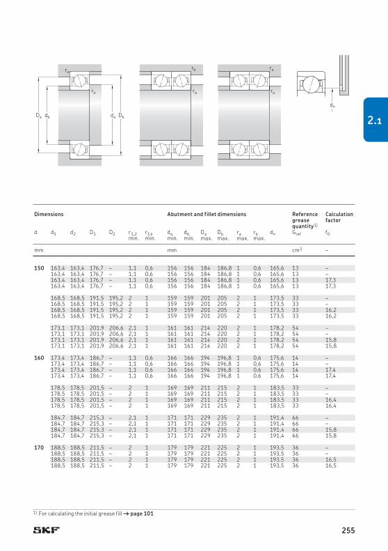
150 190 20 48,8 68 2,2 5 300 8 500 1,1 71830 ACD/P4 – – 150 163,4 163,4 176,7 – 1,1 0,6 156 156 184 186,8 1 0,6 165,6 13 –190 20 48,8 68 2,2 6 300 10 000 0,98 71830 ACD/HCP4 – – 163,4 163,4 176,7 – 1,1 0,6 156 156 184 186,8 1 0,6 165,6 13 –190 20 52 72 2,36 6 000 9 000 1,1 71830 CD/P4 – – 163,4 163,4 176,7 – 1,1 0,6 156 156 184 186,8 1 0,6 165,6 13 17,3190 20 52 72 2,36 7 000 11 000 0,98 71830 CD/HCP4 – – 163,4 163,4 176,7 – 1,1 0,6 156 156 184 186,8 1 0,6 165,6 13 17,3
210 28 119 140 4,5 5 600 8 500 2,55 71930 ACD/P4A S H1, L 168,5 168,5 191,5 195,2 2 1 159 159 201 205 2 1 173,5 33 –210 28 119 140 4,5 6 700 10 000 2,05 71930 ACD/HCP4A S H1, L 168,5 168,5 191,5 195,2 2 1 159 159 201 205 2 1 173,5 33 –210 28 125 146 4,75 6 300 9 500 2,55 71930 CD/P4A S H1, L 168,5 168,5 191,5 195,2 2 1 159 159 201 205 2 1 173,5 33 16,2210 28 125 146 4,75 7 500 11 000 2,05 71930 CD/HCP4A S H1, L 168,5 168,5 191,5 195,2 2 1 159 159 201 205 2 1 173,5 33 16,2
225 35 163 180 5,6 5 300 8 000 4,15 7030 ACD/P4A S H1, L 173,1 173,1 201,9 206,6 2,1 1 161 161 214 220 2 1 178,2 54 –225 35 163 180 5,6 6 700 10 000 3,45 7030 ACD/HCP4A S H1, L 173,1 173,1 201,9 206,6 2,1 1 161 161 214 220 2 1 178,2 54 –225 35 172 190 5,85 6 000 9 000 4,15 7030 CD/P4A S H1, L 173,1 173,1 201,9 206,6 2,1 1 161 161 214 220 2 1 178,2 54 15,8225 35 172 190 5,85 7 000 11 000 3,45 7030 CD/HCP4A S H1, L 173,1 173,1 201,9 206,6 2,1 1 161 161 214 220 2 1 178,2 54 15,8
160 200 20 50,7 75 2,36 5 000 8 000 1,25 71832 ACD/P4 – – 160 173,4 173,4 186,7 – 1,1 0,6 166 166 194 196,8 1 0,6 175,6 14 –200 20 50,7 75 2,36 6 000 9 500 1,1 71832 ACD/HCP4 – – 173,4 173,4 186,7 – 1,1 0,6 166 166 194 196,8 1 0,6 175,6 14 –200 20 54 78 2,5 5 600 8 500 1,25 71832 CD/P4 – – 173,4 173,4 186,7 – 1,1 0,6 166 166 194 196,8 1 0,6 175,6 14 17,4200 20 54 78 2,5 6 700 10 000 1,1 71832 CD/HCP4 – – 173,4 173,4 186,7 – 1,1 0,6 166 166 194 196,8 1 0,6 175,6 14 17,4
220 28 124 153 4,75 5 300 8 000 2,7 71932 ACD/P4A – H1, L 178,5 178,5 201,5 – 2 1 169 169 211 215 2 1 183,5 33 –220 28 124 153 4,75 6 300 9 500 2,25 71932 ACD/HCP4A – H1, L 178,5 178,5 201,5 – 2 1 169 169 211 215 2 1 183,5 33 –220 28 130 160 5 6 000 9 000 2,7 71932 CD/P4A – H1, L 178,5 178,5 201,5 – 2 1 169 169 211 215 2 1 183,5 33 16,4220 28 130 160 5 7 500 11 000 2,25 71932 CD/HCP4A – H1, L 178,5 178,5 201,5 – 2 1 169 169 211 215 2 1 183,5 33 16,4
240 38 182 204 6,2 5 000 7 500 5,15 7032 ACD/P4A – H1, L 184,7 184,7 215,3 – 2,1 1 171 171 229 235 2 1 191,4 66 –240 38 182 204 6,2 6 300 9 500 4,25 7032 ACD/HCP4A – H1, L 184,7 184,7 215,3 – 2,1 1 171 171 229 235 2 1 191,4 66 –240 38 195 216 6,55 5 600 8 500 5,15 7032 CD/P4A – H1, L 184,7 184,7 215,3 – 2,1 1 171 171 229 235 2 1 191,4 66 15,8240 38 195 216 6,55 6 700 11 000 4,25 7032 CD/HCP4A – H1, L 184,7 184,7 215,3 – 2,1 1 171 171 229 235 2 1 191,4 66 15,8
170 230 28 124 160 4,8 5 000 7 500 2,85 71934 ACD/P4A – H1 170 188,5 188,5 211,5 – 2 1 179 179 221 225 2 1 193,5 36 –230 28 124 160 4,8 6 000 9 000 2,35 71934 ACD/HCP4A – H1 188,5 188,5 211,5 – 2 1 179 179 221 225 2 1 193,5 36 –230 28 133 166 5,1 5 600 8 500 2,85 71934 CD/P4A – H1 188,5 188,5 211,5 – 2 1 179 179 221 225 2 1 193,5 36 16,5230 28 133 166 5,1 7 000 10 000 2,35 71934 CD/HCP4A – H1 188,5 188,5 211,5 – 2 1 179 179 221 225 2 1 193,5 36 16,5
1) For calculating the initial grease fill † page 101
Db
ra
ra
dadbDa
rb
ra
ra
ra
dn
Principal dimensions
Basic load ratings
Fatigue load limit
Attainable speeds Mass2) Designation Available variants Dimensions Abutment and fillet dimensions Reference grease quantity1)
Calculation factorGrease
lubricationOil-air lubrica-tion2)
Sealing solu-tion1)
Direct oil-air lubrication3)dynamic static
d D B C C0 Pu d d1 d2 D1 D2 r1,2 r3,4 da db Da Db ra rb dn Gref f0min. min. min. min. max. max. max. max.
mm kN kN r/min kg – – mm mm cm3 –
255
2.1

260 42 199 232 6,7 4 800 7 000 7 7034 ACD/P4A – H1, L 198,7 198,7 231,3 – 2,1 1,1 181 181 249 254 2 1 205,8 84 –260 42 199 232 6,7 6 000 9 000 5,95 7034 ACD/HCP4A – H1, L 198,7 198,7 231,3 – 2,1 1,1 181 181 249 254 2 1 205,8 84 –260 42 212 245 7,1 5 300 8 000 7 7034 CD/P4A – H1, L 198,7 198,7 231,3 – 2,1 1,1 181 181 249 254 2 1 205,8 84 15,9260 42 212 245 7,1 6 300 10 000 5,95 7034 CD/HCP4A – H1, L 198,7 198,7 231,3 – 2,1 1,1 181 181 249 254 2 1 205,8 84 15,9
180 250 33 159 200 5,85 4 800 7 000 4,2 71936 ACD/P4A – H1 180 201,6 201,6 228,4 – 2 1 189 189 241 245 2 1 207,4 54 –250 33 159 200 5,85 5 600 8 500 3,5 71936 ACD/HCP4A – H1 201,6 201,6 228,4 – 2 1 189 189 241 245 2 1 207,4 54 –250 33 168 212 6,1 5 300 8 000 4,2 71936 CD/P4A – H1 201,6 201,6 228,4 – 2 1 189 189 241 245 2 1 207,4 54 16,3250 33 168 212 6,1 6 700 9 500 3,5 71936 CD/HCP4A – H1 201,6 201,6 228,4 – 2 1 189 189 241 245 2 1 207,4 54 16,3
280 46 229 275 7,65 4 300 6 300 9,1 7036 ACD/P4A – H1, L 211,8 211,8 248,2 – 2,1 1,1 191 191 269 274 2 1 219,7 111 –280 46 229 275 7,65 5 300 8 000 7,7 7036 ACD/HCP4A – H1, L 211,8 211,8 248,2 – 2,1 1,1 191 191 269 274 2 1 219,7 111 –280 46 242 290 8,15 5 000 7 500 9,1 7036 CD/P4A – H1, L 211,8 211,8 248,2 – 2,1 1,1 191 191 269 274 2 1 219,7 111 15,7280 46 242 290 8,15 6 000 9 000 7,7 7036 CD/HCP4A – H1, L 211,8 211,8 248,2 – 2,1 1,1 191 191 269 274 2 1 219,7 111 15,7
190 260 33 163 208 5,85 4 500 6 700 4,35 71938 ACD/P4A – H1 190 211,6 211,6 238,4 – 2 1 199 199 251 255 2 1 217,4 57 –260 33 163 208 5,85 5 300 8 000 3,65 71938 ACD/HCP4A – H1 211,6 211,6 238,4 – 2 1 199 199 251 255 2 1 217,4 57 –260 33 172 220 6,2 5 000 7 500 4,35 71938 CD/P4A – H1 211,6 211,6 238,4 – 2 1 199 199 251 255 2 1 217,4 57 16,4260 33 172 220 6,2 6 300 9 000 3,65 71938 CD/HCP4A – H1 211,6 211,6 238,4 – 2 1 199 199 251 255 2 1 217,4 57 16,4
290 46 234 290 8 4 300 6 300 9,5 7038 ACD/P4A – H1 221,8 221,8 258,2 – 2,1 1,1 201 201 279 284 2 1 229,7 114 –290 46 234 290 8 5 300 8 000 8,05 7038 ACD/HCP4A – H1 221,8 221,8 258,2 – 2,1 1,1 201 201 279 284 2 1 229,7 114 –290 46 247 305 8,3 4 800 7 000 9,5 7038 CD/P4A – H1 221,8 221,8 258,2 – 2,1 1,1 201 201 279 284 2 1 229,7 114 15,9290 46 247 305 8,3 5 600 9 000 8,05 7038 CD/HCP4A – H1 221,8 221,8 258,2 – 2,1 1,1 201 201 279 284 2 1 229,7 114 15,9
200 280 38 199 250 6,8 4 300 6 300 6,1 71940 ACD/P4A – H1 200 224,7 224,7 255,3 – 2,1 1 209 209 271 275 2 1 231,4 81 –280 38 199 250 6,8 5 000 7 500 5,1 71940 ACD/HCP4A – H1 224,7 224,7 255,3 – 2,1 1 209 209 271 275 2 1 231,4 81 –280 38 208 265 7,2 4 800 7 000 6,1 71940 CD/P4A – H1 224,7 224,7 255,3 – 2,1 1 209 209 271 275 2 1 231,4 81 16,3280 38 208 265 7,2 6 000 8 500 5,1 71940 CD/HCP4A – H1 224,7 224,7 255,3 – 2,1 1 209 209 271 275 2 1 231,4 81 16,3
310 51 281 365 9,8 4 000 6 000 12,5 7040 ACD/P4A – H1 233,9 233,9 276,1 – 2,1 1,1 211 211 299 304 2 1 243,2 153 –310 51 281 365 9,8 5 000 7 500 10 7040 ACD/HCP4A – H1 233,9 233,9 276,1 – 2,1 1,1 211 211 299 304 2 1 243,2 153 –310 51 296 390 10,2 4 500 6 700 12,5 7040 CD/P4A – H1 233,9 233,9 276,1 – 2,1 1,1 211 211 299 304 2 1 243,2 153 15,6310 51 296 390 10,2 5 300 8 000 10 7040 CD/HCP4A – H1 233,9 233,9 276,1 – 2,1 1,1 211 211 299 304 2 1 243,2 153 15,6
170cont.
1) Designation suffix H, H1, L or L1. For details, refer to Direct oilair lubrication († page 136).
2.1 Angular contact ball bearings d 170 – 200 mm
Principal dimensions
Basic load ratings
Fatigue load limit
Attainable speeds Mass Designation Available variants Dimensions Abutment and fillet dimensions Reference grease quantity1)
Calculation factorGrease
lubricationOil-air lubrication
Sealing solution
Direct oil-air lubrication1)dynamic static
d D B C C0 Pu d d1 d2 D1 D2 r1,2 r3,4 da db Da Db ra rb dn Gref f0min. min. min. min. max. max. max. max.
mm kN kN r/min kg – – mm mm cm3 –
d1d2
r1
r1
r3
r1
r4r2
r2r2
D1D d
B
256

260 42 199 232 6,7 4 800 7 000 7 7034 ACD/P4A – H1, L 198,7 198,7 231,3 – 2,1 1,1 181 181 249 254 2 1 205,8 84 –260 42 199 232 6,7 6 000 9 000 5,95 7034 ACD/HCP4A – H1, L 198,7 198,7 231,3 – 2,1 1,1 181 181 249 254 2 1 205,8 84 –260 42 212 245 7,1 5 300 8 000 7 7034 CD/P4A – H1, L 198,7 198,7 231,3 – 2,1 1,1 181 181 249 254 2 1 205,8 84 15,9260 42 212 245 7,1 6 300 10 000 5,95 7034 CD/HCP4A – H1, L 198,7 198,7 231,3 – 2,1 1,1 181 181 249 254 2 1 205,8 84 15,9
180 250 33 159 200 5,85 4 800 7 000 4,2 71936 ACD/P4A – H1 180 201,6 201,6 228,4 – 2 1 189 189 241 245 2 1 207,4 54 –250 33 159 200 5,85 5 600 8 500 3,5 71936 ACD/HCP4A – H1 201,6 201,6 228,4 – 2 1 189 189 241 245 2 1 207,4 54 –250 33 168 212 6,1 5 300 8 000 4,2 71936 CD/P4A – H1 201,6 201,6 228,4 – 2 1 189 189 241 245 2 1 207,4 54 16,3250 33 168 212 6,1 6 700 9 500 3,5 71936 CD/HCP4A – H1 201,6 201,6 228,4 – 2 1 189 189 241 245 2 1 207,4 54 16,3
280 46 229 275 7,65 4 300 6 300 9,1 7036 ACD/P4A – H1, L 211,8 211,8 248,2 – 2,1 1,1 191 191 269 274 2 1 219,7 111 –280 46 229 275 7,65 5 300 8 000 7,7 7036 ACD/HCP4A – H1, L 211,8 211,8 248,2 – 2,1 1,1 191 191 269 274 2 1 219,7 111 –280 46 242 290 8,15 5 000 7 500 9,1 7036 CD/P4A – H1, L 211,8 211,8 248,2 – 2,1 1,1 191 191 269 274 2 1 219,7 111 15,7280 46 242 290 8,15 6 000 9 000 7,7 7036 CD/HCP4A – H1, L 211,8 211,8 248,2 – 2,1 1,1 191 191 269 274 2 1 219,7 111 15,7
190 260 33 163 208 5,85 4 500 6 700 4,35 71938 ACD/P4A – H1 190 211,6 211,6 238,4 – 2 1 199 199 251 255 2 1 217,4 57 –260 33 163 208 5,85 5 300 8 000 3,65 71938 ACD/HCP4A – H1 211,6 211,6 238,4 – 2 1 199 199 251 255 2 1 217,4 57 –260 33 172 220 6,2 5 000 7 500 4,35 71938 CD/P4A – H1 211,6 211,6 238,4 – 2 1 199 199 251 255 2 1 217,4 57 16,4260 33 172 220 6,2 6 300 9 000 3,65 71938 CD/HCP4A – H1 211,6 211,6 238,4 – 2 1 199 199 251 255 2 1 217,4 57 16,4
290 46 234 290 8 4 300 6 300 9,5 7038 ACD/P4A – H1 221,8 221,8 258,2 – 2,1 1,1 201 201 279 284 2 1 229,7 114 –290 46 234 290 8 5 300 8 000 8,05 7038 ACD/HCP4A – H1 221,8 221,8 258,2 – 2,1 1,1 201 201 279 284 2 1 229,7 114 –290 46 247 305 8,3 4 800 7 000 9,5 7038 CD/P4A – H1 221,8 221,8 258,2 – 2,1 1,1 201 201 279 284 2 1 229,7 114 15,9290 46 247 305 8,3 5 600 9 000 8,05 7038 CD/HCP4A – H1 221,8 221,8 258,2 – 2,1 1,1 201 201 279 284 2 1 229,7 114 15,9
200 280 38 199 250 6,8 4 300 6 300 6,1 71940 ACD/P4A – H1 200 224,7 224,7 255,3 – 2,1 1 209 209 271 275 2 1 231,4 81 –280 38 199 250 6,8 5 000 7 500 5,1 71940 ACD/HCP4A – H1 224,7 224,7 255,3 – 2,1 1 209 209 271 275 2 1 231,4 81 –280 38 208 265 7,2 4 800 7 000 6,1 71940 CD/P4A – H1 224,7 224,7 255,3 – 2,1 1 209 209 271 275 2 1 231,4 81 16,3280 38 208 265 7,2 6 000 8 500 5,1 71940 CD/HCP4A – H1 224,7 224,7 255,3 – 2,1 1 209 209 271 275 2 1 231,4 81 16,3
310 51 281 365 9,8 4 000 6 000 12,5 7040 ACD/P4A – H1 233,9 233,9 276,1 – 2,1 1,1 211 211 299 304 2 1 243,2 153 –310 51 281 365 9,8 5 000 7 500 10 7040 ACD/HCP4A – H1 233,9 233,9 276,1 – 2,1 1,1 211 211 299 304 2 1 243,2 153 –310 51 296 390 10,2 4 500 6 700 12,5 7040 CD/P4A – H1 233,9 233,9 276,1 – 2,1 1,1 211 211 299 304 2 1 243,2 153 15,6310 51 296 390 10,2 5 300 8 000 10 7040 CD/HCP4A – H1 233,9 233,9 276,1 – 2,1 1,1 211 211 299 304 2 1 243,2 153 15,6
170cont.
1) For calculating the initial grease fill † page 101
Db
ra
ra
dadbDa
rb
ra
ra
ra
dn
Principal dimensions
Basic load ratings
Fatigue load limit
Attainable speeds Mass Designation Available variants Dimensions Abutment and fillet dimensions Reference grease quantity1)
Calculation factorGrease
lubricationOil-air lubrication
Sealing solution
Direct oil-air lubrication1)dynamic static
d D B C C0 Pu d d1 d2 D1 D2 r1,2 r3,4 da db Da Db ra rb dn Gref f0min. min. min. min. max. max. max. max.
mm kN kN r/min kg – – mm mm cm3 –
257
2.1

220 300 38 208 285 7,5 3 800 5 600 6,6 71944 ACD/P4A – L 220 244,7 244,7 275,3 – 2,1 1 231 231 289 295 2 1 251,4 84 –300 38 208 285 7,5 4 500 6 700 5,55 71944 ACD/HCP4A – L 244,7 244,7 275,3 – 2,1 1 231 231 289 295 2 1 251,4 84 –300 38 221 300 7,8 4 300 6 300 6,6 71944 CD/P4A – L 244,7 244,7 275,3 – 2,1 1 231 231 289 295 2 1 251,4 84 16,5300 38 221 300 7,8 5 300 7 500 5,55 71944 CD/HCP4A – L 244,7 244,7 275,3 – 2,1 1 231 231 289 295 2 1 251,4 84 16,5
340 56 319 440 11 3 600 5 300 16 7044 ACD/P4A – – 257 257 303 – 3 1,5 233 233 327 334 2,5 1,5 267,1 201 –340 56 319 440 11 4 500 6 700 13 7044 ACD/HCP4A – – 257 257 303 – 3 1,5 233 233 327 334 2,5 1,5 267,1 201 –340 56 338 455 11,6 4 000 6 000 16 7044 CD/P4A – – 257 257 303 – 3 1,5 233 233 327 334 2,5 1,5 267,1 201 15,6340 56 338 455 11,6 4 800 7 500 13 7044 CD/HCP4A – – 257 257 303 – 3 1,5 233 233 327 334 2,5 1,5 267,1 201 15,6
240 320 38 216 305 7,8 3 200 4 800 8,5 71948 ACD/P4A – L 240 264,7 264,7 295,3 – 2,1 1 251 251 309 315 2 1 271,4 93 –320 38 216 305 7,8 3 800 5 600 6 71948 ACD/HCP4A – L 264,7 264,7 295,3 – 2,1 1 251 251 309 315 2 1 271,4 93 –320 38 229 325 8,15 3 800 5 600 8,5 71948 CD/P4A – L 264,7 264,7 295,3 – 2,1 1 251 251 309 315 2 1 271,4 93 16,7320 38 229 325 8,15 4 800 6 700 6 71948 CD/HCP4A – L 264,7 264,7 295,3 – 2,1 1 251 251 309 315 2 1 271,4 93 16,7
360 56 325 465 11,4 3 400 5 000 17 7048 ACD/P4A – – 277 277 323 – 3 1,5 253 253 347 354 2,5 1,5 287 216 –360 56 325 465 11,4 4 300 6 300 14 7048 ACD/HCP4A – – 277 277 323 – 3 1,5 253 253 347 354 2,5 1,5 287 216 –360 56 345 490 12 3 800 5 600 17 7048 CD/P4A – – 277 277 323 – 3 1,5 253 253 347 354 2,5 1,5 287 216 15,8360 56 345 490 12 4 500 7 000 14 7048 CD/HCP4A – – 277 277 323 – 3 1,5 253 253 347 354 2,5 1,5 287 216 15,8
260 360 46 265 400 9,65 2 800 4 300 12 71952 ACD/P4A – L 260 291,8 291,8 328,2 – 2,1 1,1 271 271 349 354 2 1 299,7 150 –360 46 265 400 9,65 3 600 5 300 10,5 71952 ACD/HCP4A – L 291,8 291,8 328,2 – 2,1 1,1 271 271 349 354 2 1 299,7 150 –360 46 281 425 10,2 3 400 5 000 12 71952 CD/P4A – L 291,8 291,8 328,2 – 2,1 1,1 271 271 349 354 2 1 299,7 150 16,5360 46 281 425 10,2 4 300 6 000 10,5 71952 CD/HCP4A – L 291,8 291,8 328,2 – 2,1 1,1 271 271 349 354 2 1 299,7 150 16,5
400 65 397 600 14 3 000 4 500 25,5 7052 ACD/P4A – – 303,2 303,2 356,8 – 4 1,5 275 275 385 393 3 1,5 315 324 –400 65 416 630 14,6 3 400 5 300 25,5 7052 CD/P4A – – 303,2 303,2 356,8 – 4 1,5 275 275 385 393 3 1,5 315 324 15,7
280 380 46 276 430 10 2 600 4 000 13 71956 ACD/P4A – – 280 311,8 311,8 348,2 – 2,1 1,1 291 291 369 374 2 1 319,7 159 –380 46 276 430 10 3 200 4 800 11 71956 ACD/HCP4A – – 311,8 311,8 348,2 – 2,1 1,1 291 291 369 374 2 1 319,7 159 –380 46 291 455 10,6 3 200 4 800 13 71956 CD/P4A – – 311,8 311,8 348,2 – 2,1 1,1 291 291 369 374 2 1 319,7 159 16,7380 46 291 455 10,6 4 000 5 600 11 71956 CD/HCP4A – – 311,8 311,8 348,2 – 2,1 1,1 291 291 369 374 2 1 319,7 159 16,7
300 420 56 351 560 12,7 2 200 3 400 23 71960 ACDMA/P4A – – 300 337 337 383 – 3 1,1 313 313 405 414 2,5 1 347 265 –420 56 351 560 12,7 2 600 4 000 19,5 71960 ACDMA/HCP4A – – 337 337 383 – 3 1,1 313 313 405 414 2,5 1 347 265 –420 56 371 600 13,4 3 000 4 500 23 71960 CDMA/P4A – – 337 337 383 – 3 1,1 313 313 405 414 2,5 1 347 265 16,3420 56 371 600 13,4 3 800 5 300 19,5 71960 CDMA/HCP4A – – 337 337 383 – 3 1,1 313 313 405 414 2,5 1 347 265 16,3
1) Designation suffix H, H1, L or L1. For details, refer to Direct oilair lubrication († page 136).
2.1 Angular contact ball bearings d 220 – 300 mm
Principal dimensions
Basic load ratings
Fatigue load limit
Attainable speeds Mass Designation Available variants Dimensions Abutment and fillet dimensions Reference grease quantity1)
Calculation factorGrease
lubricationOil-air lubrication
Sealing solution
Direct oil-air lubrication1)dynamic static
d D B C C0 Pu d d1 d2 D1 D2 r1,2 r3,4 da db Da Db ra rb dn Gref f0min. min. min. min. max. max. max. max.
mm kN kN r/min kg – – mm mm cm3 –
d1d2
r1
r1
r3
r1
r4r2
r2r2
D1D d
B
258

220 300 38 208 285 7,5 3 800 5 600 6,6 71944 ACD/P4A – L 220 244,7 244,7 275,3 – 2,1 1 231 231 289 295 2 1 251,4 84 –300 38 208 285 7,5 4 500 6 700 5,55 71944 ACD/HCP4A – L 244,7 244,7 275,3 – 2,1 1 231 231 289 295 2 1 251,4 84 –300 38 221 300 7,8 4 300 6 300 6,6 71944 CD/P4A – L 244,7 244,7 275,3 – 2,1 1 231 231 289 295 2 1 251,4 84 16,5300 38 221 300 7,8 5 300 7 500 5,55 71944 CD/HCP4A – L 244,7 244,7 275,3 – 2,1 1 231 231 289 295 2 1 251,4 84 16,5
340 56 319 440 11 3 600 5 300 16 7044 ACD/P4A – – 257 257 303 – 3 1,5 233 233 327 334 2,5 1,5 267,1 201 –340 56 319 440 11 4 500 6 700 13 7044 ACD/HCP4A – – 257 257 303 – 3 1,5 233 233 327 334 2,5 1,5 267,1 201 –340 56 338 455 11,6 4 000 6 000 16 7044 CD/P4A – – 257 257 303 – 3 1,5 233 233 327 334 2,5 1,5 267,1 201 15,6340 56 338 455 11,6 4 800 7 500 13 7044 CD/HCP4A – – 257 257 303 – 3 1,5 233 233 327 334 2,5 1,5 267,1 201 15,6
240 320 38 216 305 7,8 3 200 4 800 8,5 71948 ACD/P4A – L 240 264,7 264,7 295,3 – 2,1 1 251 251 309 315 2 1 271,4 93 –320 38 216 305 7,8 3 800 5 600 6 71948 ACD/HCP4A – L 264,7 264,7 295,3 – 2,1 1 251 251 309 315 2 1 271,4 93 –320 38 229 325 8,15 3 800 5 600 8,5 71948 CD/P4A – L 264,7 264,7 295,3 – 2,1 1 251 251 309 315 2 1 271,4 93 16,7320 38 229 325 8,15 4 800 6 700 6 71948 CD/HCP4A – L 264,7 264,7 295,3 – 2,1 1 251 251 309 315 2 1 271,4 93 16,7
360 56 325 465 11,4 3 400 5 000 17 7048 ACD/P4A – – 277 277 323 – 3 1,5 253 253 347 354 2,5 1,5 287 216 –360 56 325 465 11,4 4 300 6 300 14 7048 ACD/HCP4A – – 277 277 323 – 3 1,5 253 253 347 354 2,5 1,5 287 216 –360 56 345 490 12 3 800 5 600 17 7048 CD/P4A – – 277 277 323 – 3 1,5 253 253 347 354 2,5 1,5 287 216 15,8360 56 345 490 12 4 500 7 000 14 7048 CD/HCP4A – – 277 277 323 – 3 1,5 253 253 347 354 2,5 1,5 287 216 15,8
260 360 46 265 400 9,65 2 800 4 300 12 71952 ACD/P4A – L 260 291,8 291,8 328,2 – 2,1 1,1 271 271 349 354 2 1 299,7 150 –360 46 265 400 9,65 3 600 5 300 10,5 71952 ACD/HCP4A – L 291,8 291,8 328,2 – 2,1 1,1 271 271 349 354 2 1 299,7 150 –360 46 281 425 10,2 3 400 5 000 12 71952 CD/P4A – L 291,8 291,8 328,2 – 2,1 1,1 271 271 349 354 2 1 299,7 150 16,5360 46 281 425 10,2 4 300 6 000 10,5 71952 CD/HCP4A – L 291,8 291,8 328,2 – 2,1 1,1 271 271 349 354 2 1 299,7 150 16,5
400 65 397 600 14 3 000 4 500 25,5 7052 ACD/P4A – – 303,2 303,2 356,8 – 4 1,5 275 275 385 393 3 1,5 315 324 –400 65 416 630 14,6 3 400 5 300 25,5 7052 CD/P4A – – 303,2 303,2 356,8 – 4 1,5 275 275 385 393 3 1,5 315 324 15,7
280 380 46 276 430 10 2 600 4 000 13 71956 ACD/P4A – – 280 311,8 311,8 348,2 – 2,1 1,1 291 291 369 374 2 1 319,7 159 –380 46 276 430 10 3 200 4 800 11 71956 ACD/HCP4A – – 311,8 311,8 348,2 – 2,1 1,1 291 291 369 374 2 1 319,7 159 –380 46 291 455 10,6 3 200 4 800 13 71956 CD/P4A – – 311,8 311,8 348,2 – 2,1 1,1 291 291 369 374 2 1 319,7 159 16,7380 46 291 455 10,6 4 000 5 600 11 71956 CD/HCP4A – – 311,8 311,8 348,2 – 2,1 1,1 291 291 369 374 2 1 319,7 159 16,7
300 420 56 351 560 12,7 2 200 3 400 23 71960 ACDMA/P4A – – 300 337 337 383 – 3 1,1 313 313 405 414 2,5 1 347 265 –420 56 351 560 12,7 2 600 4 000 19,5 71960 ACDMA/HCP4A – – 337 337 383 – 3 1,1 313 313 405 414 2,5 1 347 265 –420 56 371 600 13,4 3 000 4 500 23 71960 CDMA/P4A – – 337 337 383 – 3 1,1 313 313 405 414 2,5 1 347 265 16,3420 56 371 600 13,4 3 800 5 300 19,5 71960 CDMA/HCP4A – – 337 337 383 – 3 1,1 313 313 405 414 2,5 1 347 265 16,3
1) For calculating the initial grease fill † page 101
Db
ra
ra
dadbDa
rb
ra
ra
ra
dn
Principal dimensions
Basic load ratings
Fatigue load limit
Attainable speeds Mass Designation Available variants Dimensions Abutment and fillet dimensions Reference grease quantity1)
Calculation factorGrease
lubricationOil-air lubrication
Sealing solution
Direct oil-air lubrication1)dynamic static
d D B C C0 Pu d d1 d2 D1 D2 r1,2 r3,4 da db Da Db ra rb dn Gref f0min. min. min. min. max. max. max. max.
mm kN kN r/min kg – – mm mm cm3 –
259
2.1

320 440 56 351 585 12,9 2 200 3 400 24 71964 ACDMA/P4A – – 320 357 357 403 – 3 1,1 333 333 425 434 2,5 1 367 282 –440 56 351 585 12,9 2 600 4 000 20,5 71964 ACDMA/HCP4A – – 357 357 403 – 3 1,1 333 333 425 434 2,5 1 367 282 –440 56 377 620 13,7 2 600 4 300 24 71964 CDMA/P4A – – 357 357 403 – 3 1,1 333 333 425 434 2,5 1 367 282 16,5440 56 377 620 13,7 3 600 5 000 20,5 71964 CDMA/HCP4A – – 357 357 403 – 3 1,1 333 333 425 434 2,5 1 367 282 16,5
340 460 56 364 640 13,4 2 000 3 200 25,5 71968 ACDMA/P4A – – 340 377 377 423 – 3 1,1 353 353 445 454 2,5 1 387 294 –460 56 364 640 13,4 2 400 3 800 21,5 71968 ACDMA/HCP4A – – 377 377 423 – 3 1,1 353 353 445 454 2,5 1 387 294 –460 56 390 670 14,3 2 400 4 000 25,5 71968 CDMA/P4A – – 377 377 423 – 3 1,1 353 353 445 454 2,5 1 387 294 16,6460 56 390 670 14,3 3 400 4 800 21,5 71968 CDMA/HCP4A – – 377 377 423 – 3 1,1 353 353 445 454 2,5 1 387 294 16,6
360 480 56 371 670 13,7 1 900 3 000 26,5 71972 ACDMA/P4A – – 360 397 397 443 – 3 1,1 373 373 465 474 2,5 1 407 313 –480 56 371 670 13,7 2 200 3 600 22,5 71972 ACDMA/HCP4A – – 397 397 443 – 3 1,1 373 373 465 474 2,5 1 407 313 –480 56 397 710 14,6 2 400 4 000 26,5 71972 CDMA/P4A – – 397 397 443 – 3 1,1 373 373 465 474 2,5 1 407 313 16,7480 56 397 710 14,6 3 400 4 800 22,5 71972 CDMA/HCP4A – – 397 397 443 – 3 1,1 373 373 465 474 2,5 1 407 313 16,7
2.1 Angular contact ball bearings d 320 – 360 mm
Principal dimensions
Basic load ratings
Fatigue load limit
Attainable speeds Mass Designation Available variants Dimensions Abutment and fillet dimensions Reference grease quantity1)
Calculation factorGrease
lubricationOil-air lubrication
Sealing solution
Direct oil-air lubricationdynamic static
d D B C C0 Pu d d1 d2 D1 D2 r1,2 r3,4 da db Da Db ra rb dn Gref f0min. min. min. min. max. max. max. max.
mm kN kN r/min kg – – mm mm cm3 –
d1d2
r1
r1
r3
r1
r4r2
r2r2
D1D d
B
260

320 440 56 351 585 12,9 2 200 3 400 24 71964 ACDMA/P4A – – 320 357 357 403 – 3 1,1 333 333 425 434 2,5 1 367 282 –440 56 351 585 12,9 2 600 4 000 20,5 71964 ACDMA/HCP4A – – 357 357 403 – 3 1,1 333 333 425 434 2,5 1 367 282 –440 56 377 620 13,7 2 600 4 300 24 71964 CDMA/P4A – – 357 357 403 – 3 1,1 333 333 425 434 2,5 1 367 282 16,5440 56 377 620 13,7 3 600 5 000 20,5 71964 CDMA/HCP4A – – 357 357 403 – 3 1,1 333 333 425 434 2,5 1 367 282 16,5
340 460 56 364 640 13,4 2 000 3 200 25,5 71968 ACDMA/P4A – – 340 377 377 423 – 3 1,1 353 353 445 454 2,5 1 387 294 –460 56 364 640 13,4 2 400 3 800 21,5 71968 ACDMA/HCP4A – – 377 377 423 – 3 1,1 353 353 445 454 2,5 1 387 294 –460 56 390 670 14,3 2 400 4 000 25,5 71968 CDMA/P4A – – 377 377 423 – 3 1,1 353 353 445 454 2,5 1 387 294 16,6460 56 390 670 14,3 3 400 4 800 21,5 71968 CDMA/HCP4A – – 377 377 423 – 3 1,1 353 353 445 454 2,5 1 387 294 16,6
360 480 56 371 670 13,7 1 900 3 000 26,5 71972 ACDMA/P4A – – 360 397 397 443 – 3 1,1 373 373 465 474 2,5 1 407 313 –480 56 371 670 13,7 2 200 3 600 22,5 71972 ACDMA/HCP4A – – 397 397 443 – 3 1,1 373 373 465 474 2,5 1 407 313 –480 56 397 710 14,6 2 400 4 000 26,5 71972 CDMA/P4A – – 397 397 443 – 3 1,1 373 373 465 474 2,5 1 407 313 16,7480 56 397 710 14,6 3 400 4 800 22,5 71972 CDMA/HCP4A – – 397 397 443 – 3 1,1 373 373 465 474 2,5 1 407 313 16,7
1) For calculating the initial grease fill † page 101
Db
ra
ra
dadbDa
rb
ra
ra
ra
dn
Principal dimensions
Basic load ratings
Fatigue load limit
Attainable speeds Mass Designation Available variants Dimensions Abutment and fillet dimensions Reference grease quantity1)
Calculation factorGrease
lubricationOil-air lubrication
Sealing solution
Direct oil-air lubricationdynamic static
d D B C C0 Pu d d1 d2 D1 D2 r1,2 r3,4 da db Da Db ra rb dn Gref f0min. min. min. min. max. max. max. max.
mm kN kN r/min kg – – mm mm cm3 –
261
2.1

Product tables3.1 Single row cylindrical roller
bearings . . . . . . . . . . . . . . . . . . . . . . 2883.2 Double row cylindrical roller
bearings . . . . . . . . . . . . . . . . . . . . . . 294
Designs and variants . . . . . . . . . . . . . . 264Single row cylindrical roller bearings . . . 264
Basic design bearings . . . . . . . . . . . . . 264High-speed design bearings . . . . . . . . 264
Double row cylindrical roller bearings . . 265Annular groove and lubrication holes . 266Bearings with a pre-ground raceway . 267
Cages . . . . . . . . . . . . . . . . . . . . . . . . . . . . 267Hybrid bearings . . . . . . . . . . . . . . . . . . . 268
Bearing data . . . . . . . . . . . . . . . . . . . . . 269(Boundary dimensions, tolerances, axial displacement)Radial internal clearance . . . . . . . . . . . . 273
Radial internal clearance or preload in mounted bearings . . . . . . . . . . . . . . . . . 275
Radial stiffness . . . . . . . . . . . . . . . . . . . 275
Equivalent bearing loads . . . . . . . . . . . 277
Attainable speeds . . . . . . . . . . . . . . . . . 277
Design considerations . . . . . . . . . . . . . . 278Adjusting for clearance or preload . . . . . 278Free space on both sides of the bearing . 280
Mounting . . . . . . . . . . . . . . . . . . . . . . . . 280Mounting a bearing in the NN 30 K series using a GB 30 series gauge . . . . . . . . . . . 282Mounting bearings with a tapered bore by measuring radial clearance prior to mounting . . . . . . . . . . . . . . . . . . . . . . . 284Mounting and dismounting, using the oil injection method . . . . . . . . . . . . . . . . . . . 285
Designation system . . . . . . . . . . . . . . . . 286
More informationBearing life and load ratings . . . . . . . . 33Requisite minimum load . . . . . . . . . . . 34Chamfer dimension limits . . . . . . . . . . 47Materials . . . . . . . . . . . . . . . . . . . . . . . 51Design considerations . . . . . . . . . . . . . 57Lubrication . . . . . . . . . . . . . . . . . . . . . 99Mounting and dismounting . . . . . . . . . 123Bearing storage . . . . . . . . . . . . . . . . . . 125Gauges . . . . . . . . . . . . . . . . . . . . . . . . . 391
Cylindrical roller bearings
263
3

Cylindrical roller bearings
Designs and variants SKF manufactures super-precision single row and double row cylindrical roller bearings in three different designs and series. The bear-ings, which can accommodate axial displace-ment of the shaft relative to the housing in both directions, are separable, i.e. the bearing ring with the roller and cage assembly can be separated from the other ring. This simplifies mounting and dismounting, particularly when load conditions require both rings to have an interference fit.
SKF super-precision cylindrical roller bear-ings are characterized by:
• high speed capability• high radial load carrying capacity• high rigidity• low friction• low cross sectional height
These bearings are therefore particularly well suited for machine tool spindles where the bearing arrangement must accommodate heavy radial loads and high speeds, while pro-viding a high degree of stiffness.
SKF super-precision single row cylindrical roller bearings have a higher speed capability than double row bearings while double row bearings are more suitable for heavier loads.
Single row cylindrical roller bearings SKF super-precision single row cylindrical roller bearings in the N 10 series († fig. 1) have, as standard, a 1:12 tapered bore (desig-nation suffix K). A tapered bore is preferred because the taper enables accurate adjust-ment of clearance or preload during mounting. The bearings have two integral flanges on the inner ring and no flanges on the outer ring. To improve lubricant flow, these bearings can be supplied with a lubrication hole in the outer ring on request.
Basic design bearingsBasic design single row cylindrical roller bear-ings are equipped as standard with a roller centred PA66 cage without glass fibre rein-forcement for bore diameters up to 80 mm (designation suffix TN), and with glass fibre reinforcement for larger sizes (designation suf-fix TN9). These bearings are well suited for most precision applications.
High-speed design bearingsThe internal geometry and cages of high-speed design single row cylindrical roller bear-ings have been optimized to accommodate higher speeds. High-speed design bearings contain fewer rollers than basic design bear-ings. They are equipped with either an asym-metrical cage, made of glass fibre reinforced PEEK (designation suffix TNHA), or a symmet-rical cage, made of carbon fibre reinforced PEEK (designation suffix PHA). Both are outer ring centred cages, designed to optimize the effectiveness of the lubricant and avoid kine-matic lubricant starvation at high speeds. When comparing the two cages, the sym met-rical PHA cage provides better guidance and promotes better lubrication conditions for superior performance.
Compared to bearings with a glass fibre reinforced PEEK cage, bearings with a carbon fibre reinforced PEEK cage can accommodate speeds up to 30% higher in grease lubricated applications and up to 15% higher when lubri-cated with an oil-air system.
For applications like the non-tool end of a motorized spindle, where the requirement for higher speed outweighs that for higher rigidity, bearings containing cages with half the num-ber of rollers can be supplied on request.
Fig. 1
264

Designs and variants
Double row cylindrical roller bearings SKF super-precision double row cylindrical roller bearings († fig. 2) are manufactured as standard in the NN 30 and NNU 49 series.
Both series are available with either a cylin-drical or a 1:12 tapered bore (designation suf-fix K). In machine tool applications, cylindrical roller bearings with a tapered bore are pre-ferred over bearings with a cylindrical bore, because the taper enables more accurate adjustment of clearance or preload during mounting.
NN 30 seriesBearings in the NN 30 series can provide a unique balance between load carrying cap-acity, rigidity and speed. They are therefore typically used as the non-tool end bearing in machine tool spindles.
NN 30 series bearings have three integral flanges on the inner ring and no flanges on the outer ring.
NNU 49 seriesBearings in the NNU 49 series, with a very low cross sectional height, provide a higher degree of stiffness than bearings in the NN 30 series, but a somewhat lower load carrying capacity.
NNU 49 series bearings have three integral flanges on the outer ring and no flanges on the inner ring.
NN 30 NNU 49
Fig. 2
265
3

Cylindrical roller bearings
Annular groove and lubrication holesTo facilitate efficient lubrication, all bearings in the NNU 49 series and bearings in the NN 30 series with a bore diameter d ≥ 140 mm, have an annular groove and three lubrication holes in the outer ring († fig. 3, designation suffix W33).
Bearings without an annular groove and lu-brication holes are typically lubricated either with the requisite minimum quantity of grease or with accurately metered, small quantities of oil or oil-air. In this case, the lubricant is de-liver ed through a nozzle, positioned to the side of the bearing († fig. 4 and product tables, page 294).
If NN 30 series bearings with a bore diam-eter d ≤ 130 mm require an annular groove and lubrication holes, check SKF for availability early in the design phase.
Fig. 3 Fig. 4
266
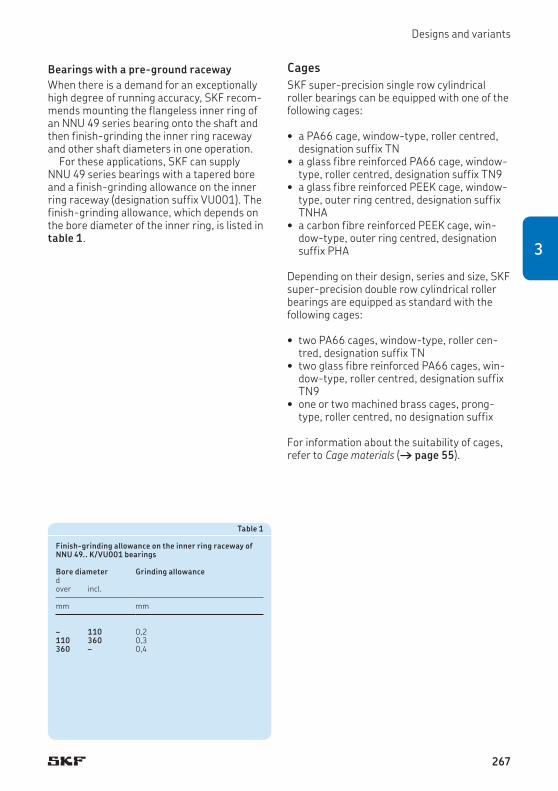
Designs and variants
Bearings with a pre-ground racewayWhen there is a demand for an exceptionally high degree of running accuracy, SKF recom-mends mounting the flangeless inner ring of an NNU 49 series bearing onto the shaft and then finish-grinding the inner ring raceway and other shaft diameters in one operation.
For these applications, SKF can supply NNU 49 series bearings with a tapered bore and a finish-grinding allowance on the inner ring raceway (designation suffix VU001). The finish-grinding allowance, which depends on the bore diameter of the inner ring, is listed in table 1.
CagesSKF super-precision single row cylindrical roller bearings can be equipped with one of the following cages:
• a PA66 cage, window-type, roller centred, designation suffix TN
• a glass fibre reinforced PA66 cage, window-type, roller centred, designation suffix TN9
• a glass fibre reinforced PEEK cage, window-type, outer ring centred, designation suffix TNHA
• a carbon fibre reinforced PEEK cage, win-dow-type, outer ring centred, designation suffix PHA
Depending on their design, series and size, SKF super-precision double row cylindrical roller bearings are equipped as standard with the following cages:
• two PA66 cages, window-type, roller cen-tred, designation suffix TN
• two glass fibre reinforced PA66 cages, win-dow-type, roller centred, designation suffix TN9
• one or two machined brass cages, prong-type, roller centred, no designation suffix
For information about the suitability of cages, refer to Cage materials († page 55).
Table 1
Finish-grinding allowance on the inner ring raceway of NNU 49.. K/VU001 bearings
Bore diameter Grinding allowancedover incl.
mm mm
– 110 0,2110 360 0,3360 – 0,4
267
3

Cylindrical roller bearings
Hybrid bearings Hybrid cylindrical roller bearings (designation suffix HC5) are available in the N 10 series and can be supplied on request in the NN 30 series. They have rings made of bearing steel and roll-ers made of bearing grade silicon nitride (ceramic). As ceramic rollers are lighter and have a higher modulus of elasticity and lower coefficient of thermal expansion than steel rollers, hybrid bearings can provide the follow-ing advantages:
• higher degree of rigidity• higher speed capability • reduced centrifugal and inertial forces
within the bearing• minimized stress at the outer ring rolling
contacts at high speeds• reduced frictional heat• less energy consumption• extended bearing and grease service life• less prone to skid smearing damage and
cage damage when subjected to frequent rapid starts and stops
• less sensitive to temperature differences within the bearing
• more accurate preload control
For additional information about silicon nitride, refer to Materials for bearing rings and rolling elements († page 51).
In order to maximize the performance of a hybrid bearing, SKF recommends using hybrid single row bearings with an outer ring centred window-type PEEK cage (designation suffix PHA or TNHA). These bearings, depending on the cage design, can attain speeds up to A = 2 200 000 mm/min, when under light load and lubricated with an oil-air system, († diagram 5, page 40). They can attain speeds up to A = 1 800 000 mm/min, when grease lubricated († diagram 6, page 42). As an option to further improve lubricant flow, bearings in the N 10 series with a lubrication hole in the outer ring can be supplied on request.
268

Bearing data
Bearing dataBoundary dimensions
ISO 15
Tolerances
For additional information († page 47)
• SP class tolerances († table 2, page 270) as standard• higher precision UP class tolerances († table 3, page 271) on
request• SP and UP class tolerances for 1:12 tapered bore († table 4,
page 272)
Axial displacement
Accommodate axial displacement of the shaft relative to the housing within certain limits († product tables). During operation, axial dis-placement occurs within the bearing and not between the bearing and shaft or housing bore. As a result, there is virtually no increase in friction.
269
3

Cylindrical roller bearings
Table 2
SP class tolerances
Inner ringd Δds
1) Vdp ΔBs VBs Kia Sdover incl. high low max. high low max. max. max.
mm µm µm µm µm µm µm
– 18 0 –5 3 0 –100 5 3 818 30 0 –6 3 0 –100 5 3 830 50 0 –8 4 0 –120 5 4 8
50 80 0 –9 5 0 –150 6 4 880 120 0 –10 5 0 –200 7 5 9120 180 0 –13 7 0 –250 8 6 10
180 250 0 –15 8 0 –300 10 8 11250 315 0 –18 9 0 –350 13 10 13315 400 0 –23 12 0 –400 15 12 15
400 500 0 –28 14 0 –450 25 12 18500 630 0 –35 18 0 –500 30 15 20630 800 0 –45 23 0 –750 35 15 23
Outer ringD ΔDs, ΔDmp
2) VDp ΔCs, VCs Kea SDover incl. high low max. max. max.
mm µm µm µm µm
30 50 0 –7 4 Values are identical to those for the inner ring of the same bearing.
5 850 80 0 –9 5 5 880 120 0 –10 5 6 9
120 150 0 –11 6 7 10150 180 0 –13 7 8 10180 250 0 –15 8 10 11
250 315 0 –18 9 11 13315 400 0 –20 10 13 13400 500 0 –23 12 15 15
500 630 0 –28 14 17 18630 800 0 –35 18 20 20800 1 000 0 –50 25 25 30
Tolerance symbols and definitions † table 4, page 481) SP tolerances for 1:12 tapered bore † table 4, page 2722) Tolerance ΔDs applies to bearings with an outside diameter D ≤ 630 mm, and tolerance ΔDmp for larger bearings.
270

Bearing data
Table 3
UP class tolerances
Inner ringd Δds
1) Vdp ΔBs VBs Kia Sdover incl. high low max. high low max. max. max.
mm µm µm µm µm µm µm
– 18 0 –4 2 0 –70 1,5 1,5 218 30 0 –5 2,5 0 –80 1,5 1,5 330 50 0 –6 3 0 –100 2 2 3
50 80 0 –7 3,5 0 –100 3 2 480 120 0 –8 4 0 –100 3 3 4120 180 0 –10 5 0 –100 4 3 5
180 250 0 –12 6 0 –150 5 4 6250 315 0 –15 8 0 –150 5 4 6315 400 0 –19 10 0 –150 6 5 7
400 500 0 –23 12 0 –200 7 5 8500 630 0 –26 13 0 –200 8 6 9630 800 0 –34 17 0 –200 10 7 11
Outer ringD ΔDs VDp ΔCs, VCs Kea SDover incl. high low max. max. max.
mm µm µm µm µm
30 50 0 –5 3 Values are identical to those for the inner ring of the same bearing.
3 250 80 0 –6 3 3 280 120 0 –7 4 3 3
120 150 0 –8 4 4 3150 180 0 –9 5 4 3180 250 0 –10 5 5 4
250 315 0 –12 6 6 4315 400 0 –14 7 7 5400 500 0 –17 9 8 5
500 630 0 –20 10 9 6630 800 0 –25 13 11 7800 1 000 0 –30 15 12 10
Tolerance symbols and definitions † table 4, page 481) UP tolerances for 1:12 tapered bore † table 4, page 272
271
3

Cylindrical roller bearings
Table 4
SP and UP class tolerances for 1:12 tapered bore
Bore diameter SP class tolerances UP class tolerancesd Δd2mp Vdp Δd1mp – Δd2mp
1) Δd2mp Vdp Δd1mp – Δd2mp1)
over incl. high low max. high low high low max. high low
mm µm µm µm µm µm µm
18 30 +10 0 3 +4 0 +6 0 2,5 +2 030 50 +12 0 4 +4 0 +7 0 3 +3 050 80 +15 0 5 +5 0 +8 0 3,5 +3 0
80 120 +20 0 5 +6 0 +10 0 4 +4 0120 180 +25 0 7 +8 0 +12 0 5 +4 0180 250 +30 0 8 +10 0 +14 0 6 +5 0
250 315 +35 0 9 +12 0 +15 0 8 +6 0315 400 +40 0 12 +12 0 +17 0 10 +6 0400 500 +45 0 14 +14 0 +19 0 12 +7 0
500 630 +50 0 18 +15 0 +20 0 13 +11 0630 800 +65 0 23 +19 0 +22 0 17 +13 0
1:12 tapered bore (half angle of taper: a = 2° 23© 9,4") Measuring distance aChamfer dimension
Bore diameter Measuring distance
rs min d aover incl.
mm mm mm
0,6 – – 2,51 – – 3,5
1,1 – 120 4120 – 5
1,5 – 120 5120 – 6
2 – 80 5,580 220 6220 – 7
2,1 – 280 7,5280 – 8,5
2,5 – 280 7,5280 – 8,5
3 – – 9,54 – – 11
5 – – 126 – – 16
Tolerance symbols and definitions † table 4, page 481) Δd1mp – Δd2mp = angle deviation over measuring length m
B
a
+ Dd1mp + Ddmp
Dd1mp Dd2mp–2
+ Dd2mp
d1
d2
d
m a
272
Designs and variants
Radial internal clearance SKF super-precision cylindrical roller bearings manufactured to the SP tolerance class are supplied with C1 radial internal clearance (no designation suffix) as standard.
On request, bearings in the N 10 and NN 30 series can also be supplied with a special reduced radial clearance (smaller than C1), when a minimum operating clearance or a preload after mounting is required. For infor-mation about clearance values and availability, contact the SKF application engineering service.
Bearings made to the SP tolerance class, particularly those in the NNU 49 series, are also available with a radial internal clearance greater than C1. When ordering, the requisite clearance should be indicated in the designa-tion by the suffix:
• SPC2 for clearance greater than C1• CN for Normal clearance, greater than SPC2• C3 for clearance greater than Normal
The values for radial internal clearance are listed in table 5 († page 274). They are in accordance with ISO 5753-1 (except for SPC2) and are valid for new, unmounted bearings under zero measuring load. SPC2 radial clear-ance values deviate from those standardized for C2. The clearance range is reduced and dis-placed toward the lower limit.
To achieve the required radial internal clear-ance, the rings of individual bearings are matched at the factory, marked with the same identification number and usually packaged together in a single box. Be sure to check that the numbers on both rings match prior to mounting. Any mismatch could have a negative impact on the radial internal clearance and the performance characteristics of the final assembly.
273
3

Cylindrical roller bearings
Table 5
Radial internal clearance of super-precision cylindrical roller bearings
Bore diameter Radial internal clearanceBearings with a cylindrical bore Bearings with a tapered bore
d C1 SPC2 Normal C3 C1 SPC2over incl. min. max. min. max. min. max. min. max. min. max. min. max.
mm µm µm
24 30 5 15 10 25 20 45 35 60 15 25 25 3530 40 5 15 12 25 25 50 45 70 15 25 25 4040 50 5 18 15 30 30 60 50 80 17 30 30 45
50 65 5 20 15 35 40 70 60 90 20 35 35 5065 80 10 25 20 40 40 75 65 100 25 40 40 6080 100 10 30 25 45 50 85 75 110 35 55 45 70
100 120 10 30 25 50 50 90 85 125 40 60 50 80120 140 10 35 30 60 60 105 100 145 45 70 60 90140 160 10 35 35 65 70 120 115 165 50 75 65 100
160 180 10 40 35 75 75 125 120 170 55 85 75 110180 200 15 45 40 80 90 145 140 195 60 90 80 120200 225 15 50 45 90 105 165 160 220 60 95 90 135
225 250 15 50 50 100 110 175 170 235 65 100 100 150250 280 20 55 55 110 125 195 190 260 75 110 110 165280 315 20 60 60 120 130 205 200 275 80 120 120 180
315 355 20 65 65 135 145 225 225 305 90 135 135 200355 400 25 75 75 150 190 280 280 370 100 150 150 225400 450 25 85 85 170 210 310 310 410 110 170 170 255
450 500 25 95 95 190 220 330 330 440 120 190 190 285500 560 25 105 105 210 240 360 360 480 130 210 210 315560 630 25 115 115 230 260 380 380 500 140 230 230 345
630 710 30 130 130 260 260 380 380 500 160 260 260 390710 800 35 145 145 290 290 425 425 565 180 290 290 435
274

Radial stiffness
Radial internal clearance or preload in mounted bearingsTo optimize running accuracy and stiffness, super-precision cylindrical roller bearings should have a minimum radial internal clear-ance or preload after mounting. Cylindrical roller bearings with a tapered bore are gener-ally mounted with preload.
The required operating clearance or preload depends on the speed, load, lubricant and required stiffness of the complete spindle / bearing system. The geometrical accuracy of the bearing seats also play a key role in being able to obtain the necessary clearance or preload. The operating temperature and tem-perature distribution within the bearing should also be taken into consideration, since a reduc-tion in operating clearance or an increase in preload may result.
Radial stiffness Radial stiffness depends on the elastic defor-mation (deflection) of the bearing under load and can be expressed as a ratio of load to deflection. However, since the relationship between deflection and load is not linear, only guideline values can be provided († table 6, page 276). These values apply to moderately preloaded, mounted bearings under static con-ditions, subjected to moderate loads.
More accurate values for radial stiffness can be calculated using advanced computer pro-grams. For additional information, contact the SKF application engineering service and refer to Bearing stiffness († page 68).
275
3

Cylindrical roller bearings
Table 6
Static radial stiffness
Bore diameter
Static radial stiffnessN 10 NN 301) NNU 491)
d with steel rollers with ceramic rollers with steel rollers
with steel rollersover TN(9) cage TNHA cage PHA cage TN(9) cage TNHA cage PHA cage
mm N/µm N/µm N/µm
25 – – – – – – 640 –30 – – – – – – 690 –35 – – – – – – 820 –
40 450 430 390 610 580 510 890 –45 480 460 410 620 590 530 940 –50 530 510 460 690 660 590 1 040 –
55 620 590 540 810 770 700 1 220 –60 680 650 590 890 850 770 1 330 –65 740 710 650 970 930 840 1 450 –
70 810 780 720 1 090 1 050 950 1 610 –75 820 790 720 1 090 1 050 960 1 610 –80 920 880 810 1 190 1 140 1 040 1 820 –
85 990 950 – 1 280 1 230 – 1 970 –90 980 940 – 1 320 1 270 – 2 010 –95 1 060 1 020 – 1 430 1 380 – 2 190 –
100 1 140 1 100 – 1 540 1 490 – 2 350 2 950105 1 140 1 100 – 1 540 1 490 – 2 330 3 040110 1 210 1 160 – 1 600 1 540 – 2 470 3 130
120 1 310 1 260 – 1 730 1 670 – 2 760 3 140130 – – – – – – 2 900 3 570140 – – – – – – 3 070 3 670
150 – – – – – – 3 310 4 160160 – – – – – – 3 540 4 310170 – – – – – – 3 790 4 460
180 – – – – – – 3 970 5 190190 – – – – – – 4 280 5 380200 – – – – – – 4 380 5 480
220 – – – – – – 4 700 5 990240 – – – – – – 5 180 6 340260 – – – – – – 5 570 6 830280 – – – – – – 6 010 7 260
1) For bearings in the NN 30 and NNU 49 series with d > 280 mm, contact the SKF application engineering service.
276

Attainable speeds
Equivalent bearing loads The equivalent dynamic bearing load can be calculated using
P = Fr
The equivalent static bearing load can be cal-culated using
P0 = Fr
whereP = equivalent dynamic bearing load [kN]P0 = equivalent static bearing load [kN]Fr = radial load [kN]
Attainable speeds The attainable speeds listed in the product tables are guideline values based on cylindrical roller bearings with a near zero radial internal clearance († Attainable speeds, page 44).
In applications where operating radial in-tern al clearance > 0,002 mm or preload is ap-plied or where seats and abutments do not meet accuracy requirements, the speed rat-ings must be reduced († Recommended shaft and housing fits and Accuracy of seats and abutments, pages 70 and 75).
The attainable speeds for preloaded bear-ings in the N 10 and NN 30 series can be esti-mated using the guideline values listed in table 7. For attainable speeds of preloaded bearings in the NNU 49 series, contact the SKF application engineering service.
Table 7
Attainable speed factor for preloaded bearings in the N 10 and NN 30 series
Preload Speed factormin. max. A = n dm
µm mm/min
0 2 ≤ 1 300 000
1 3 ≤ 1 000 000
2 5 ≤ 500 000
n = rotational speed [r/min]dm = bearing mean diameter [mm]
= 0,5 (d + D)
277
3

Cylindrical roller bearings
Design considerationsAdjusting for clearance or preloadWhen mounting a cylindrical roller bearing with a tapered bore, radial internal clearance or preload is determined by how far the bear-ing inner ring is driven up on its tapered seat. The further up the seat the ring is driven, the more it expands and the less radial internal clearance there will be, until eventually, there is a radial preload in the bearing. To quickly and accurately obtain the specified clearance or preload when mounting a bearing, SKF recom-mends using gauges († page 391). Gauges are particularly useful when mounting two or three bearings as it is not necessary to meas-ure and calculate the axial drive-up distance for each bearing († Mounting, page 280).
If obtaining an exact radial internal clear-ance or preload is not critical or SKF gauges are not available, it is possible to determine the required axial drive-up distance. To do this, locate the assembled bearing at a reference point on the shaft and measure the radial internal clearance with a dial indicator pos-ition ed on the outside surface of the outer ring († Mounting bearings with a tapered bore by measuring radial clearance prior to mounting, page 284).
With the radial internal clearance measured using either of the above methods, the axial drive-up distance can be obtained using
e cBa = ——— 1 000
If the bearing is to be mounted against a dis-tance ring († fig. 5), the width of the distance ring must be adjusted to obtain the value Ba.
If there is no fixed abutment and a threaded nut is used to drive the inner ring assembly up on its tapered seat, the angle through which the nut should be turned can be calculated using
360 e ca = ———– 1 000 p
whereBa = axial drive-up [mm] a = requisite nut tightening angle [°]c = measured radial internal clearance at the
reference point•plus the required preload [µm] for
preload •minus the required clearance [µm] for
clearance•minus the adjustment [µm] for an
interference fit in the housing bore when not using SKF gauges († Mounting bearings with a tapered bore by measuring radial clearance prior to mounting)
e = a factor depending on the diameter ratio of the hollow shaft and the bearing series († fig. 6 and table 8)
p = thread lead of the nut [mm]
For mounting procedures for super-precision cylindrical roller bearings, refer to Mounting († page 280).
Ba
Fig. 5
278

Design considerations
Calculation example Determine the axial drive-up for a double row cylindrical roller bearing mounted on a hollow shaft. Input data:
• bearing NN 3040 K/SPW33• measured residual radial internal clear-
ance = 10 µm• requisite preload = 2 µm• mean bearing seat diameter dom = 203 mm• internal diameter of the hollow shaft
di = 140 mm
From table 8 e = 18 for di /dom = 140/203 = 0,69
With c = 10 + 2 = 12 µm
18 ¥ 12Ba = ———— = 0,216 mm 1 000
di
dom
Fig. 6 Table 8
Factor e
Hollow shaft diameter ratio
Factor e for bearings in the series
di/dom N 10 K, NN 30 K NNU 49 Kover incl.
– 0,2 12,5 120,2 0,3 14,5 130,3 0,4 15 14
0,4 0,5 16 150,5 0,6 17 180,6 0,7 18 17
279
3

Cylindrical roller bearings
Free space on both sides of the bearing To be sure that N 10 and NN 30 series bear-ings, with a polymer cage (designation suffix TN, TN9, TNHA or PHA), can accommodate axial displacement of the shaft relative to the housing, free space must be provided on both sides of the bearing († fig. 7). This prevents damage that might otherwise occur if the cage makes contact with an adjacent component. The minimum width of this free space should be
Ca = 1,3 s
whereCa = minimum width of free space [mm]s = permissible axial displacement from the
normal position of one bearing ring relative to the other [mm] († product tables)
s
Ca
Ca
Fig. 7
Axial drive-up
Fig. 8
MountingTo achieve the required radial internal clear-ance, the rings of individual bearings are matched at the factory, marked with the same identification number and usually packaged together in a single box. Be sure to check that the numbers on both rings match prior to mounting. Any mismatch could have a negative impact on the radial internal clearance and the performance characteristics of the final assembly.
When mounting super-precision cylindrical roller bearings with a tapered bore, the radial internal clearance or preload must be adjusted accurately. This is done by driving the inner ring up on its tapered shaft seat († fig. 8). The resulting expansion of the inner ring deter-mines the internal clearance or preload in the mounted bearing. For proper mounting, the inside or outside envelope diameter of the roller set must be accurately measured. SKF internal clearance gauges in the GB 30 and GB 10 († fig. 9) or GB 49 († fig. 10) series enable simple and accurate measurements. For additional information about internal clearance gauges, refer to Gauges († page 391).
Mounting a cylindrical roller bearing in the NN 30 K series using a GB 30 series gauge is described in the following. The same pro ced-ure can be applied when mounting cylindrical roller bearings in the N 10 K series using either a GB 10 or GB 30 series gauge. A similar pro-cedure can be applied when mounting cy lin-
280

Mounting
Fig. 9
GB 3006 … GB 3020GB 1010 … GB 1020
GB 3021 … GB 3068
Fig. 10
GB 4920 … GB 4938 GB 4940 … GB 4960
281
3

Cylindrical roller bearings
dric al roller bearings in the NNU 49 K series using a GB 49 series gauge.
When mounting without the assistance of an internal clearance gauge, be sure that the ac-curacy of the readings is sufficient for the application requirements.
Mounting a bearing in the NN 30 K series using a GB 30 series gaugeTo mount a bearing in the NN 30 K series, SKF recommends using a GB 30 gauge († page 400), a bore gauge and the appro-priate hydraulic tools to drive the bearing up onto its seat. Provisions for oil injection are useful for dismounting († Provisions for mounting and dismounting, page 88). The typical mounting procedure comprises the fol-lowing steps:
1 Mounting the outer ring – Heat the housing to the appropriate tem-perature and slide the outer ring in position.
2 Preparing the gauge – Let the housing and the outer ring cool to ambient temperature. Set a bore gauge to the raceway diameter and zero the indica-tor († fig. 11).
– Place the gauge in the centre of the gaug-ing zone of the GB 30 gauge († fig. 12). Adjust the GB 30 gauge, using the adjust-ment screw until the bore gauge indicates zero minus the correction value listed in the GB 30 user instructions.
– Increase the inside diameter of the GB 30 gauge by the value of the desired preload or reduce the inside diameter by the value of the desired clearance, using the adjust-ment screw. Then set the GB 30 gauge indicator to zero. Keep this indicator set-ting unchanged during the mounting process.
3 Mounting the inner ring (trial) – Coat the tapered shaft seat with a thin layer of light oil and push the inner ring, roller and cage assembly until the bearing bore makes good contact with its seat.
– Expand the GB 30 gauge with the adjust-ment screw, place it over the roller set and release the adjustment screw so that the gauge makes contact with the roller set († fig. 13).
– Drive the inner ring roller and cage assembly together with the gauge further up on its seat until the indicator on the gauge reads zero. The inner ring is now in the correct position for the desired preload or clearance.
– Expand the gauge using the adjustment screw and remove it from the roller and cage assembly.
4 Mounting the inner ring (final) – Measure the distance between the bear-ing side face and the shaft abutment using gauge blocks († fig. 14). Take measure-ments at different diametrical positions to check accuracy and misalignment. The difference between the single measure-ments should not exceed 3 to 4 µm.
– Grind a pre-machined spacer ring to the measured width.
– Remove the inner ring, mount the spacer ring, and drive up the inner ring again, until it firmly abuts the spacer ring.
– Place the GB 30 gauge over the roller set as described earlier. Release the adjust-ment screw. If the indicator reads zero again, the inner ring is properly mounted. Remove the gauge and locate the inner ring, using a suitable locking device.
282

Mounting
Fig. 11
Fig. 13
Fig. 12
Fig. 14
283
3

Cylindrical roller bearings
Mounting bearings with a tapered bore by measuring radial clearance prior to mountingIf obtaining an exact radial internal clearance or preload is not critical or if SKF gauges are not available, it is possible to determine the required axial drive-up distance. To do this, locate the assembled bearing at a reference point on the shaft and measure the radial internal clearance with a dial indicator positioned on the outside surface of the outer ring. This method does not take into account that the outer ring is compressed when mounted with an interference fit in the housing. To com-pensate for this, it can be assumed that the outer ring raceway diameter will decrease by 80% of the diametric interference fit. The pro-cedure comprises the following steps:
1 Mounting the inner ring (trial) – Coat the tapered shaft seat with a thin layer of light oil and push the assembled bearing in place until the bearing bore makes good contact with its seat.
– There should still be clearance between the outer ring and rollers.
– Keep in mind that small bearings may have only 15 µm internal clearance prior to mounting and that an axial drive-up of 0,1 mm causes a clearance reduction of ~ 8 µm.
2 Measuring the internal clearance prior to mounting – Place a spacer ring onto the shaft and position it between the bearing inner ring side face and drive-up device. The spacer, which must be parallel to the bearing inner ring side face, is there to guide the outer ring side face when measuring clearance († fig. 15).
– To measure the radial clearance, place a dial indicator on the outer ring circumfer-ence and set the indicator to zero.
– Holding the outer ring firmly against the spacer, move the outer ring up or down, and measure the total displacement. This measured distance is the radial clearance in the bearing, prior to mounting.
– Do not apply excessive force to the outer ring. Elastic deformation may cause measurement errors.
3 Determine the required axial drive-up dis-tance Ba († Adjusting for clearance or preload, page 278) remembering to include the allowance for outer ring interfer-ence fit, if one exists.
4 Determining the spacer ring width – Measure the distance L between the bearing side face and the shaft abutment († fig. 15). Take measurements at dif-ferent diametrical positions to check ac-curacy and misalignment. The difference between the single measurements should not exceed 3 to 4 µm.
– Calculate the required width of the spacer ring using
B = L – Ba
whereB = required width of the spacer ringL = mean measured distance from the
bearing inner ring to the abutment Ba = the required axial drive-up distance
to achieve the desired clearance reduction or preload († Adjusting for clearance or preload, page 278)
L
Fig. 15
284

Mounting
Fig. 16
5 Mounting the bearing (final) – Grind the pre-machined spacer ring to the required width.
– Remove the assembled bearing, mount the spacer ring, and drive up the inner ring roller and cage assembly again until it firmly abuts the spacer ring.
– Locate the inner ring using a suitable locking device.
– Heat the housing to the required tem-pera ture and mount the outer ring.
Mounting and dismounting, using the oil injection methodParticularly where large bearings are involved, it is often necessary to make provisions during the design stage, to facilitate mounting and dismounting of a bearing, or even to make it possible at all.
For super-precision cylindrical roller bear-ings with a bore diameter d > 80 mm, SKF rec-ommends the oil injection method. With the oil injection method, oil under high pressure is injected via ducts and distribution grooves between the bearing and bearing seat to form an oil film († fig. 16). This oil film separates the mating surfaces and considerably reduces the friction between them and virtually elim in-ates the risk of damaging the bearing or the spindle shaft. This method is typically used when mounting or dismounting bearings directly on tapered shaft seats. Where bear-ings with a cylindrical bore are concerned, the oil injection method can only be used for dismounting.
To apply the oil injection method, the spindle must contain ducts and grooves († Provisions for mounting and dismounting, page 88).
285
3
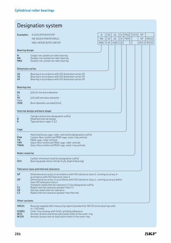
Cylindrical roller bearings
Designation system
Bearing design
N Single row cylindrical roller bearingNN Double row cylindrical roller bearingNNU Double row cylindrical roller bearing
Dimension series
10 Bearing in accordance with ISO dimension series 1030 Bearing in accordance with ISO dimension series 3049 Bearing in accordance with ISO dimension series 49
Bearing size
05 (x5) 25 mm bore diameterto92 (x5) 460 mm bore diameterfrom/500 Bore diameter uncoded [mm]
Internal design and bore shape
– Cylindrical bore (no designation suffix)B Modified internal designK Tapered bore, taper 1:12
Cage
– Machined brass cage, roller centred (no designation suffix)PHA Carbon fibre reinforced PEEK cage, outer ring centredTN PA66 cage, roller centredTN9 Glass fibre reinforced PA66 cage, roller centredTNHA Glass fibre reinforced PEEK cage, outer ring centred
Roller material
– Carbon chromium steel (no designation suffix)HC5 Bearing grade silicon nitride Si3N4 (hybrid bearing)
Tolerance class and internal clearance
SP Dimensional accuracy in accordance with ISO tolerance class 5, running accuracy in accordance with ISO tolerance class 4
UP Dimensional accuracy in accordance with ISO tolerance class 4, running accuracy better than ISO tolerance class 4
– Standard radial internal clearance C1 (no designation suffix)C2 Radial internal clearance greater than C1CN Normal radial internal clearanceC3 Radial internal clearance greater than Normal
Other variants
VR521 Bearing supplied with measuring report (standard for NN 30 series bearings with d > 130 mm)
VU001 Inner ring raceway with finish-grinding allowanceW33 Annular groove and three lubrication holes in the outer ringW33X Annular groove and six lubrication holes in the outer ring
Examples: N 1016 KPHA/HC5SP N 10 16 K PHA / HC5 SP
NN 3020 KTN9/SPVR521 NN 30 20 K TN9 / SP VR521
NNU 49/500 B/SPC3W33X NNU 49 /500 B / SPC3 W33X
286

Designation system
287
3

40 68 15 23,3 25 2,9 30 000 36 000 0,19 N 1008 KPHA/SP 40 50,6 61 1 0,6 2 – 45 62 63 1 52,1 3,168 15 23,3 25 2,9 32 000 38 000 0,17 N 1008 KPHA/HC5SP 50,6 61 1 0,6 2 – 45 62 63 1 52,1 3,168 15 24,2 26,5 3,05 22 000 32 000 0,19 N 1008 KTNHA/SP 50,6 61 1 0,6 2 1,5 45 62 63 1 – 2,568 15 24,2 26,5 3,05 26 000 36 000 0,17 N 1008 KTNHA/HC5SP 50,6 61 1 0,6 2 1,5 45 62 63 1 – 2,568 15 25,1 28 3,2 15 000 17 000 0,19 N 1008 KTN/SP 50,6 61 1 0,6 2 – 45 62 63 1 60 2,368 15 25,1 28 3,2 18 000 20 000 0,17 N 1008 KTN/HC5SP 50,6 61 1 0,6 2 – 45 62 63 1 60 2,3
45 75 16 27 30 3,45 28 000 34 000 0,24 N 1009 KPHA/SP 45 56,3 67,5 1 0,6 2 – 50 69 70 1 57,9 4,175 16 27 30 3,45 30 000 36 000 0,2 N 1009 KPHA/HC5SP 56,3 67,5 1 0,6 2 – 50 69 70 1 57,9 4,175 16 28,1 31 3,65 20 000 28 000 0,24 N 1009 KTNHA/SP 56,3 67,5 1 0,6 2 1,5 50 69 70 1 – 3,275 16 28,1 31 3,65 22 000 32 000 0,21 N 1009 KTNHA/HC5SP 56,3 67,5 1 0,6 2 1,5 50 69 70 1 – 3,275 16 29,2 32,5 3,8 14 000 15 000 0,24 N 1009 KTN/SP 56,3 67,5 1 0,6 2 – 50 69 70 1 66,4 2,975 16 29,2 32,5 3,8 16 000 18 000 0,22 N 1009 KTN/HC5SP 56,3 67,5 1 0,6 2 – 50 69 70 1 66,4 2,9
50 80 16 28,6 33,5 3,8 26 000 30 000 0,26 N 1010 KPHA/SP 50 61,3 72,5 1 0,6 2 – 55 74 75 1 63 4,480 16 28,6 33,5 3,8 28 000 32 000 0,22 N 1010 KPHA/HC5SP 61,3 72,5 1 0,6 2 – 55 74 75 1 63 4,480 16 29,7 34,5 4,05 19 000 26 000 0,26 N 1010 KTNHA/SP 61,3 72,5 1 0,6 2 1,5 55 74 75 1 – 3,580 16 29,7 34,5 4,05 20 000 28 000 0,23 N 1010 KTNHA/HC5SP 61,3 72,5 1 0,6 2 1,5 55 74 75 1 – 3,580 16 30,8 36,5 4,25 13 000 14 000 0,26 N 1010 KTN/SP 61,3 72,5 1 0,6 2 – 55 74 75 1 71,4 3,280 16 30,8 36,5 4,25 15 000 17 000 0,23 N 1010 KTN/HC5SP 61,3 72,5 1 0,6 2 – 55 74 75 1 71,4 3,2
55 90 18 37,4 44 5,2 22 000 28 000 0,38 N 1011 KPHA/SP 55 68,2 81 1,1 0,6 2,5 – 61,5 82 83,5 1 70,1 6,190 18 37,4 44 5,2 24 000 30 000 0,32 N 1011 KPHA/HC5SP 68,2 81 1,1 0,6 2,5 – 61,5 82 83,5 1 70,1 6,190 18 39,1 46,5 5,5 17 000 24 000 0,39 N 1011 KTNHA/SP 68,2 81 1,1 0,6 2,5 1,5 61,5 82 83,5 1 – 4,990 18 39,1 46,5 5,5 19 000 26 000 0,35 N 1011 KTNHA/HC5SP 68,2 81 1,1 0,6 2,5 1,5 61,5 82 83,5 1 – 4,990 18 40,2 48 5,7 12 000 13 000 0,39 N 1011 KTN/SP 68,2 81 1,1 0,6 2,5 – 61,5 82 83,5 1 79,8 4,490 18 40,2 48 5,7 13 000 15 000 0,35 N 1011 KTN/HC5SP 68,2 81 1,1 0,6 2,5 – 61,5 82 83,5 1 79,8 4,4
60 95 18 40,2 49 5,85 20 000 26 000 0,4 N 1012 KPHA/SP 60 73,3 86,1 1,1 0,6 2,5 – 66,5 87 88,5 1 75,2 6,595 18 40,2 49 5,85 22 000 28 000 0,33 N 1012 KPHA/HC5SP 73,3 86,1 1,1 0,6 2,5 – 66,5 87 88,5 1 75,2 6,595 18 41,3 51 6,1 16 000 22 000 0,41 N 1012 KTNHA/SP 73,3 86,1 1,1 0,6 2,5 1,5 66,5 87 88,5 1 – 5,295 18 41,3 51 6,1 18 000 24 000 0,37 N 1012 KTNHA/HC5SP 73,3 86,1 1,1 0,6 2,5 1,5 66,5 87 88,5 1 – 5,295 18 42,9 53 6,3 11 000 12 000 0,41 N 1012 KTN/SP 73,3 86,1 1,1 0,6 2,5 – 66,5 87 88,5 1 85 4,795 18 42,9 53 6,3 12 000 14 000 0,37 N 1012 KTN/HC5SP 73,3 86,1 1,1 0,6 2,5 – 66,5 87 88,5 1 85 4,7
s1ss
TN(9), PHA TNHA
d1
r2
r4
r1
r3
dED
B
Principal dimensions Basic load ratings Fatigue
load limitAttainable speeds Mass Designation Dimensions Abutment and fillet dimensions Reference
grease quantity1)
Grease lubrica-tion
Oil-air lubrication
Bearing with a tapered boredynamic static
d D B C C0 Pu d d1 E r1,2 r3,4 s2) s12) da Da Da ra dn
3) Grefmin. min. min. min. max. max.
mm kN kN r/min kg – mm mm cm3
3.1 Single row cylindrical roller bearingsd 40 – 60 mm
288

40 68 15 23,3 25 2,9 30 000 36 000 0,19 N 1008 KPHA/SP 40 50,6 61 1 0,6 2 – 45 62 63 1 52,1 3,168 15 23,3 25 2,9 32 000 38 000 0,17 N 1008 KPHA/HC5SP 50,6 61 1 0,6 2 – 45 62 63 1 52,1 3,168 15 24,2 26,5 3,05 22 000 32 000 0,19 N 1008 KTNHA/SP 50,6 61 1 0,6 2 1,5 45 62 63 1 – 2,568 15 24,2 26,5 3,05 26 000 36 000 0,17 N 1008 KTNHA/HC5SP 50,6 61 1 0,6 2 1,5 45 62 63 1 – 2,568 15 25,1 28 3,2 15 000 17 000 0,19 N 1008 KTN/SP 50,6 61 1 0,6 2 – 45 62 63 1 60 2,368 15 25,1 28 3,2 18 000 20 000 0,17 N 1008 KTN/HC5SP 50,6 61 1 0,6 2 – 45 62 63 1 60 2,3
45 75 16 27 30 3,45 28 000 34 000 0,24 N 1009 KPHA/SP 45 56,3 67,5 1 0,6 2 – 50 69 70 1 57,9 4,175 16 27 30 3,45 30 000 36 000 0,2 N 1009 KPHA/HC5SP 56,3 67,5 1 0,6 2 – 50 69 70 1 57,9 4,175 16 28,1 31 3,65 20 000 28 000 0,24 N 1009 KTNHA/SP 56,3 67,5 1 0,6 2 1,5 50 69 70 1 – 3,275 16 28,1 31 3,65 22 000 32 000 0,21 N 1009 KTNHA/HC5SP 56,3 67,5 1 0,6 2 1,5 50 69 70 1 – 3,275 16 29,2 32,5 3,8 14 000 15 000 0,24 N 1009 KTN/SP 56,3 67,5 1 0,6 2 – 50 69 70 1 66,4 2,975 16 29,2 32,5 3,8 16 000 18 000 0,22 N 1009 KTN/HC5SP 56,3 67,5 1 0,6 2 – 50 69 70 1 66,4 2,9
50 80 16 28,6 33,5 3,8 26 000 30 000 0,26 N 1010 KPHA/SP 50 61,3 72,5 1 0,6 2 – 55 74 75 1 63 4,480 16 28,6 33,5 3,8 28 000 32 000 0,22 N 1010 KPHA/HC5SP 61,3 72,5 1 0,6 2 – 55 74 75 1 63 4,480 16 29,7 34,5 4,05 19 000 26 000 0,26 N 1010 KTNHA/SP 61,3 72,5 1 0,6 2 1,5 55 74 75 1 – 3,580 16 29,7 34,5 4,05 20 000 28 000 0,23 N 1010 KTNHA/HC5SP 61,3 72,5 1 0,6 2 1,5 55 74 75 1 – 3,580 16 30,8 36,5 4,25 13 000 14 000 0,26 N 1010 KTN/SP 61,3 72,5 1 0,6 2 – 55 74 75 1 71,4 3,280 16 30,8 36,5 4,25 15 000 17 000 0,23 N 1010 KTN/HC5SP 61,3 72,5 1 0,6 2 – 55 74 75 1 71,4 3,2
55 90 18 37,4 44 5,2 22 000 28 000 0,38 N 1011 KPHA/SP 55 68,2 81 1,1 0,6 2,5 – 61,5 82 83,5 1 70,1 6,190 18 37,4 44 5,2 24 000 30 000 0,32 N 1011 KPHA/HC5SP 68,2 81 1,1 0,6 2,5 – 61,5 82 83,5 1 70,1 6,190 18 39,1 46,5 5,5 17 000 24 000 0,39 N 1011 KTNHA/SP 68,2 81 1,1 0,6 2,5 1,5 61,5 82 83,5 1 – 4,990 18 39,1 46,5 5,5 19 000 26 000 0,35 N 1011 KTNHA/HC5SP 68,2 81 1,1 0,6 2,5 1,5 61,5 82 83,5 1 – 4,990 18 40,2 48 5,7 12 000 13 000 0,39 N 1011 KTN/SP 68,2 81 1,1 0,6 2,5 – 61,5 82 83,5 1 79,8 4,490 18 40,2 48 5,7 13 000 15 000 0,35 N 1011 KTN/HC5SP 68,2 81 1,1 0,6 2,5 – 61,5 82 83,5 1 79,8 4,4
60 95 18 40,2 49 5,85 20 000 26 000 0,4 N 1012 KPHA/SP 60 73,3 86,1 1,1 0,6 2,5 – 66,5 87 88,5 1 75,2 6,595 18 40,2 49 5,85 22 000 28 000 0,33 N 1012 KPHA/HC5SP 73,3 86,1 1,1 0,6 2,5 – 66,5 87 88,5 1 75,2 6,595 18 41,3 51 6,1 16 000 22 000 0,41 N 1012 KTNHA/SP 73,3 86,1 1,1 0,6 2,5 1,5 66,5 87 88,5 1 – 5,295 18 41,3 51 6,1 18 000 24 000 0,37 N 1012 KTNHA/HC5SP 73,3 86,1 1,1 0,6 2,5 1,5 66,5 87 88,5 1 – 5,295 18 42,9 53 6,3 11 000 12 000 0,41 N 1012 KTN/SP 73,3 86,1 1,1 0,6 2,5 – 66,5 87 88,5 1 85 4,795 18 42,9 53 6,3 12 000 14 000 0,37 N 1012 KTN/HC5SP 73,3 86,1 1,1 0,6 2,5 – 66,5 87 88,5 1 85 4,7
daDa
ra
TN(9) PHA
Principal dimensions Basic load ratings Fatigue
load limitAttainable speeds Mass Designation Dimensions Abutment and fillet dimensions Reference
grease quantity1)
Grease lubrica-tion
Oil-air lubrication
Bearing with a tapered boredynamic static
d D B C C0 Pu d d1 E r1,2 r3,4 s2) s12) da Da Da ra dn
3) Grefmin. min. min. min. max. max.
mm kN kN r/min kg – mm mm cm3
1) For calculating the initial grease fill † page 1012) Permissible axial displacement from the normal position of one bearing ring relative to the other.3) For bearings equipped with a TNHA cage, contact the SKF application engineering service.
dn
dn
289
3.1

65 100 18 42,9 54 6,3 20 000 24 000 0,43 N 1013 KPHA/SP 65 78,2 91 1,1 0,6 2,5 – 71,5 92 93,5 1 80,1 6,9100 18 42,9 54 6,3 22 000 26 000 0,35 N 1013 KPHA/HC5SP 78,2 91 1,1 0,6 2,5 – 71,5 92 93,5 1 80,1 6,9100 18 44 56 6,55 15 000 20 000 0,44 N 1013 KTNHA/SP 78,2 91 1,1 0,6 2,5 1,5 71,5 92 93,5 1 – 5,5100 18 44 56 6,55 17 000 22 000 0,39 N 1013 KTNHA/HC5SP 78,2 91 1,1 0,6 2,5 1,5 71,5 92 93,5 1 – 5,5100 18 44,6 58,5 6,8 10 000 11 000 0,44 N 1013 KTN/SP 78,2 91 1,1 0,6 2,5 – 71,5 92 93,5 1 89,7 5100 18 44,6 58,5 6,8 11 000 13 000 0,39 N 1013 KTN/HC5SP 78,2 91 1,1 0,6 2,5 – 71,5 92 93,5 1 89,7 5
70 110 20 53,9 69,5 8 18 000 22 000 0,61 N 1014 KPHA/SP 70 85,6 100 1,1 0,6 3 – 76,5 101 103,5 1 87,7 9,2110 20 53,9 69,5 8 20 000 24 000 0,5 N 1014 KPHA/HC5SP 85,6 100 1,1 0,6 3 – 76,5 101 103,5 1 87,7 9,2110 20 55 72 8,3 13 000 19 000 0,62 N 1014 KTNHA/SP 85,6 100 1,1 0,6 3 1,5 76,5 101 103,5 1 – 7,2110 20 55 72 8,3 15 000 20 000 0,55 N 1014 KTNHA/HC5SP 85,6 100 1,1 0,6 3 1,5 76,5 101 103,5 1 – 7,2110 20 57,2 75 8,65 9 500 10 000 0,62 N 1014 KTN/SP 85,6 100 1,1 0,6 3 – 76,5 101 103,5 1 98,5 6,7110 20 57,2 75 8,65 10 000 12 000 0,55 N 1014 KTN/HC5SP 85,6 100 1,1 0,6 3 – 76,5 101 103,5 1 98,5 6,7
75 115 20 52,8 69,5 8,15 17 000 20 000 0,64 N 1015 KPHA/SP 75 90,6 105 1,1 0,6 3 – 81,5 106 108,5 1 92,7 9,6115 20 52,8 69,5 8,15 19 000 22 000 0,53 N 1015 KPHA/HC5SP 90,6 105 1,1 0,6 3 – 81,5 106 108,5 1 92,7 9,6115 20 55 72 8,5 13 000 18 000 0,65 N 1015 KTNHA/SP 90,6 105 1,1 0,6 3 1,5 81,5 106 108,5 1 – 7,7115 20 55 72 8,5 14 000 20 000 0,57 N 1015 KTNHA/HC5SP 90,6 105 1,1 0,6 3 1,5 81,5 106 108,5 1 – 7,7115 20 56,1 75 8,8 9 000 9 500 0,65 N 1015 KTN/SP 90,6 105 1,1 0,6 3 – 81,5 106 108,5 1 103,5 7,1115 20 56,1 75 8,8 9 500 11 000 0,57 N 1015 KTN/HC5SP 90,6 105 1,1 0,6 3 – 81,5 106 108,5 1 103,5 7,1
80 125 22 66 86,5 10,2 16 000 19 000 0,88 N 1016 KPHA/SP 80 97 113 1,1 0,6 3 – 86,5 114 118,5 1 99,3 13125 22 66 86,5 10,2 18 000 20 000 0,73 N 1016 KPHA/HC5SP 97 113 1,1 0,6 3 – 86,5 114 118,5 1 99,3 13125 22 67,1 90 10,6 12 000 16 000 0,88 N 1016 KTNHA/SP 97 113 1,1 0,6 3 1 86,5 114 118,5 1 – 9,8125 22 67,1 90 10,6 13 000 18 000 0,79 N 1016 KTNHA/HC5SP 97 113 1,1 0,6 3 1 86,5 114 118,5 1 – 9,8125 22 69,3 93 11 8 500 9 000 0,89 N 1016 KTN/SP 97 113 1,1 0,6 3 – 86,5 114 118,5 1 111,4 9125 22 69,3 93 11 9 000 10 000 0,79 N 1016 KTN/HC5SP 97 113 1,1 0,6 3 – 86,5 114 118,5 1 111,4 9
85 130 22 70,4 98 11,2 11 000 16 000 0,89 N 1017 KTNHA/SP 85 102 118 1,1 0,6 3 1 91,5 119 123,5 1 – 10130 22 70,4 98 11,2 13 000 17 000 0,79 N 1017 KTNHA/HC5SP 102 118 1,1 0,6 3 1 91,5 119 123,5 1 – 10130 22 73,7 102 11,6 8 000 8 500 0,9 N 1017 KTN9/SP 102 118 1,1 0,6 3 – 91,5 119 123,5 1 116,5 9,2130 22 73,7 102 11,6 9 000 10 000 0,8 N 1017 KTN9/HC5SP 102 118 1,1 0,6 3 – 91,5 119 123,5 1 116,5 9,2
90 140 24 76,5 104 12,5 10 000 14 000 1,2 N 1018 KTNHA/SP 90 109,4 127 1,5 1 3 1 98 129 132 1,5 – 14140 24 76,5 104 12,5 12 000 16 000 1,05 N 1018 KTNHA/HC5SP 109,4 127 1,5 1 3 1 98 129 132 1,5 – 14140 24 79,2 108 12,9 7 000 8 000 1,2 N 1018 KTN9/SP 109,4 127 1,5 1 3 – 98 129 132 1,5 125,4 12140 24 79,2 108 12,9 8 500 9 500 1,1 N 1018 KTN9/HC5SP 109,4 127 1,5 1 3 – 98 129 132 1,5 125,4 12
3.1 Single row cylindrical roller bearingsd 65 – 90 mm
Principal dimensions Basic load ratings Fatigue
load limitAttainable speeds Mass Designation Dimensions Abutment and fillet dimensions Reference
grease quantity1)
Grease lubrica-tion
Oil-air lubrication
Bearing with a tapered boredynamic static
d D B C C0 Pu d d1 E r1,2 r3,4 s2) s12) da Da Da ra dn
3) Grefmin. min. min. min. max. max.
mm kN kN r/min kg – mm mm cm3
s1ss
d1
r2
r4
r1
r3
dED
B
TN(9), PHA TNHA
290

65 100 18 42,9 54 6,3 20 000 24 000 0,43 N 1013 KPHA/SP 65 78,2 91 1,1 0,6 2,5 – 71,5 92 93,5 1 80,1 6,9100 18 42,9 54 6,3 22 000 26 000 0,35 N 1013 KPHA/HC5SP 78,2 91 1,1 0,6 2,5 – 71,5 92 93,5 1 80,1 6,9100 18 44 56 6,55 15 000 20 000 0,44 N 1013 KTNHA/SP 78,2 91 1,1 0,6 2,5 1,5 71,5 92 93,5 1 – 5,5100 18 44 56 6,55 17 000 22 000 0,39 N 1013 KTNHA/HC5SP 78,2 91 1,1 0,6 2,5 1,5 71,5 92 93,5 1 – 5,5100 18 44,6 58,5 6,8 10 000 11 000 0,44 N 1013 KTN/SP 78,2 91 1,1 0,6 2,5 – 71,5 92 93,5 1 89,7 5100 18 44,6 58,5 6,8 11 000 13 000 0,39 N 1013 KTN/HC5SP 78,2 91 1,1 0,6 2,5 – 71,5 92 93,5 1 89,7 5
70 110 20 53,9 69,5 8 18 000 22 000 0,61 N 1014 KPHA/SP 70 85,6 100 1,1 0,6 3 – 76,5 101 103,5 1 87,7 9,2110 20 53,9 69,5 8 20 000 24 000 0,5 N 1014 KPHA/HC5SP 85,6 100 1,1 0,6 3 – 76,5 101 103,5 1 87,7 9,2110 20 55 72 8,3 13 000 19 000 0,62 N 1014 KTNHA/SP 85,6 100 1,1 0,6 3 1,5 76,5 101 103,5 1 – 7,2110 20 55 72 8,3 15 000 20 000 0,55 N 1014 KTNHA/HC5SP 85,6 100 1,1 0,6 3 1,5 76,5 101 103,5 1 – 7,2110 20 57,2 75 8,65 9 500 10 000 0,62 N 1014 KTN/SP 85,6 100 1,1 0,6 3 – 76,5 101 103,5 1 98,5 6,7110 20 57,2 75 8,65 10 000 12 000 0,55 N 1014 KTN/HC5SP 85,6 100 1,1 0,6 3 – 76,5 101 103,5 1 98,5 6,7
75 115 20 52,8 69,5 8,15 17 000 20 000 0,64 N 1015 KPHA/SP 75 90,6 105 1,1 0,6 3 – 81,5 106 108,5 1 92,7 9,6115 20 52,8 69,5 8,15 19 000 22 000 0,53 N 1015 KPHA/HC5SP 90,6 105 1,1 0,6 3 – 81,5 106 108,5 1 92,7 9,6115 20 55 72 8,5 13 000 18 000 0,65 N 1015 KTNHA/SP 90,6 105 1,1 0,6 3 1,5 81,5 106 108,5 1 – 7,7115 20 55 72 8,5 14 000 20 000 0,57 N 1015 KTNHA/HC5SP 90,6 105 1,1 0,6 3 1,5 81,5 106 108,5 1 – 7,7115 20 56,1 75 8,8 9 000 9 500 0,65 N 1015 KTN/SP 90,6 105 1,1 0,6 3 – 81,5 106 108,5 1 103,5 7,1115 20 56,1 75 8,8 9 500 11 000 0,57 N 1015 KTN/HC5SP 90,6 105 1,1 0,6 3 – 81,5 106 108,5 1 103,5 7,1
80 125 22 66 86,5 10,2 16 000 19 000 0,88 N 1016 KPHA/SP 80 97 113 1,1 0,6 3 – 86,5 114 118,5 1 99,3 13125 22 66 86,5 10,2 18 000 20 000 0,73 N 1016 KPHA/HC5SP 97 113 1,1 0,6 3 – 86,5 114 118,5 1 99,3 13125 22 67,1 90 10,6 12 000 16 000 0,88 N 1016 KTNHA/SP 97 113 1,1 0,6 3 1 86,5 114 118,5 1 – 9,8125 22 67,1 90 10,6 13 000 18 000 0,79 N 1016 KTNHA/HC5SP 97 113 1,1 0,6 3 1 86,5 114 118,5 1 – 9,8125 22 69,3 93 11 8 500 9 000 0,89 N 1016 KTN/SP 97 113 1,1 0,6 3 – 86,5 114 118,5 1 111,4 9125 22 69,3 93 11 9 000 10 000 0,79 N 1016 KTN/HC5SP 97 113 1,1 0,6 3 – 86,5 114 118,5 1 111,4 9
85 130 22 70,4 98 11,2 11 000 16 000 0,89 N 1017 KTNHA/SP 85 102 118 1,1 0,6 3 1 91,5 119 123,5 1 – 10130 22 70,4 98 11,2 13 000 17 000 0,79 N 1017 KTNHA/HC5SP 102 118 1,1 0,6 3 1 91,5 119 123,5 1 – 10130 22 73,7 102 11,6 8 000 8 500 0,9 N 1017 KTN9/SP 102 118 1,1 0,6 3 – 91,5 119 123,5 1 116,5 9,2130 22 73,7 102 11,6 9 000 10 000 0,8 N 1017 KTN9/HC5SP 102 118 1,1 0,6 3 – 91,5 119 123,5 1 116,5 9,2
90 140 24 76,5 104 12,5 10 000 14 000 1,2 N 1018 KTNHA/SP 90 109,4 127 1,5 1 3 1 98 129 132 1,5 – 14140 24 76,5 104 12,5 12 000 16 000 1,05 N 1018 KTNHA/HC5SP 109,4 127 1,5 1 3 1 98 129 132 1,5 – 14140 24 79,2 108 12,9 7 000 8 000 1,2 N 1018 KTN9/SP 109,4 127 1,5 1 3 – 98 129 132 1,5 125,4 12140 24 79,2 108 12,9 8 500 9 500 1,1 N 1018 KTN9/HC5SP 109,4 127 1,5 1 3 – 98 129 132 1,5 125,4 12
1) For calculating the initial grease fill † page 1012) Permissible axial displacement from the normal position of one bearing ring relative to the other.3) For bearings equipped with a TNHA cage, contact the SKF application engineering service.
Principal dimensions Basic load ratings Fatigue
load limitAttainable speeds Mass Designation Dimensions Abutment and fillet dimensions Reference
grease quantity1)
Grease lubrica-tion
Oil-air lubrication
Bearing with a tapered boredynamic static
d D B C C0 Pu d d1 E r1,2 r3,4 s2) s12) da Da Da ra dn
3) Grefmin. min. min. min. max. max.
mm kN kN r/min kg – mm mm cm3
daDa
ra
TN(9) PHA
dn
dn
291
3.1

95 145 24 80,9 112 13,4 10 000 14 000 1,25 N 1019 KTNHA/SP 95 114,4 132 1,5 1 3 1 103 134 137 1,5 – 14145 24 80,9 112 13,4 11 000 15 000 1,1 N 1019 KTNHA/HC5SP 114,4 132 1,5 1 3 1 103 134 137 1,5 – 14145 24 84,2 116 14 6 700 7 500 1,25 N 1019 KTN9/SP 114,4 132 1,5 1 3 – 103 134 137 1,5 130,3 13145 24 84,2 116 14 8 000 9 000 1,1 N 1019 KTN9/HC5SP 114,4 132 1,5 1 3 – 103 134 137 1,5 130,3 13
100 150 24 85,8 120 14,3 9 500 13 000 1,3 N 1020 KTNHA/SP 100 119,4 137 1,5 1 3 1 108 139 142 1,5 – 14150 24 85,8 120 14,3 11 000 15 000 1,15 N 1020 KTNHA/HC5SP 119,4 137 1,5 1 3 1 108 139 142 1,5 – 14150 24 88 125 14,6 6 700 7 500 1,3 N 1020 KTN9/SP 119,4 137 1,5 1 3 – 108 139 142 1,5 135,3 13150 24 88 125 14,6 7 500 8 500 1,15 N 1020 KTN9/HC5SP 119,4 137 1,5 1 3 – 108 139 142 1,5 135,3 13
105 160 26 108 146 17,3 9 000 13 000 1,65 N 1021 KTNHA/SP 105 125,2 146 2 1,1 3 1 114 148 151 2 – 18160 26 108 146 17,3 10 000 14 000 1,45 N 1021 KTNHA/HC5SP 125,2 146 2 1,1 3 1 114 148 151 2 – 18160 26 110 153 18 6 300 7 000 1,65 N 1021 KTN9/SP 125,2 146 2 1,1 3 – 114 148 151 2 144,1 18160 26 110 153 18 7 000 8 000 1,45 N 1021 KTN9/HC5SP 125,2 146 2 1,1 3 – 114 148 151 2 144,1 18
110 170 28 125 173 20 8 500 12 000 2,05 N 1022 KTNHA/SP 110 132,6 155 2 1,1 3 1 119 157 161 2 – 21170 28 125 173 20 9 500 13 000 1,8 N 1022 KTNHA/HC5SP 132,6 155 2 1,1 3 1 119 157 161 2 – 21170 28 128 180 20,8 5 600 6 300 2,05 N 1022 KTN9/SP 132,6 155 2 1,1 3 – 119 157 161 2 153 21170 28 128 180 20,8 6 700 7 500 1,8 N 1022 KTN9/HC5SP 132,6 155 2 1,1 3 – 119 157 161 2 153 21
120 180 28 130 186 21,2 8 000 11 000 2,2 N 1024 KTNHA/SP 120 142,6 165 2 1,1 3 1 129 167 171 2 – 34180 28 130 186 21,2 9 000 12 000 1,9 N 1024 KTNHA/HC5SP 142,6 165 2 1,1 3 1 129 167 171 2 – 34180 28 134 196 22 5 300 6 000 2,2 N 1024 KTN9/SP 142,6 165 2 1,1 3 – 129 167 171 2 162,9 22180 28 134 196 22 6 300 7 000 1,9 N 1024 KTN9/HC5SP 142,6 165 2 1,1 3 – 129 167 171 2 162,9 22
3.1 Single row cylindrical roller bearingsd 95 – 120 mm
Principal dimensions Basic load ratings Fatigue
load limitAttainable speeds Mass Designation Dimensions Abutment and fillet dimensions Reference
grease quantity1)
Grease lubrica-tion
Oil-air lubrication
Bearing with a tapered boredynamic static
d D B C C0 Pu d d1 E r1,2 r3,4 s2) s12) da Da Da ra dn
3) Grefmin. min. min. min. max. max.
mm kN kN r/min kg – mm mm cm3
s1ss
d1
r2
r4
r1
r3
dED
B
TN(9) TNHA
292

95 145 24 80,9 112 13,4 10 000 14 000 1,25 N 1019 KTNHA/SP 95 114,4 132 1,5 1 3 1 103 134 137 1,5 – 14145 24 80,9 112 13,4 11 000 15 000 1,1 N 1019 KTNHA/HC5SP 114,4 132 1,5 1 3 1 103 134 137 1,5 – 14145 24 84,2 116 14 6 700 7 500 1,25 N 1019 KTN9/SP 114,4 132 1,5 1 3 – 103 134 137 1,5 130,3 13145 24 84,2 116 14 8 000 9 000 1,1 N 1019 KTN9/HC5SP 114,4 132 1,5 1 3 – 103 134 137 1,5 130,3 13
100 150 24 85,8 120 14,3 9 500 13 000 1,3 N 1020 KTNHA/SP 100 119,4 137 1,5 1 3 1 108 139 142 1,5 – 14150 24 85,8 120 14,3 11 000 15 000 1,15 N 1020 KTNHA/HC5SP 119,4 137 1,5 1 3 1 108 139 142 1,5 – 14150 24 88 125 14,6 6 700 7 500 1,3 N 1020 KTN9/SP 119,4 137 1,5 1 3 – 108 139 142 1,5 135,3 13150 24 88 125 14,6 7 500 8 500 1,15 N 1020 KTN9/HC5SP 119,4 137 1,5 1 3 – 108 139 142 1,5 135,3 13
105 160 26 108 146 17,3 9 000 13 000 1,65 N 1021 KTNHA/SP 105 125,2 146 2 1,1 3 1 114 148 151 2 – 18160 26 108 146 17,3 10 000 14 000 1,45 N 1021 KTNHA/HC5SP 125,2 146 2 1,1 3 1 114 148 151 2 – 18160 26 110 153 18 6 300 7 000 1,65 N 1021 KTN9/SP 125,2 146 2 1,1 3 – 114 148 151 2 144,1 18160 26 110 153 18 7 000 8 000 1,45 N 1021 KTN9/HC5SP 125,2 146 2 1,1 3 – 114 148 151 2 144,1 18
110 170 28 125 173 20 8 500 12 000 2,05 N 1022 KTNHA/SP 110 132,6 155 2 1,1 3 1 119 157 161 2 – 21170 28 125 173 20 9 500 13 000 1,8 N 1022 KTNHA/HC5SP 132,6 155 2 1,1 3 1 119 157 161 2 – 21170 28 128 180 20,8 5 600 6 300 2,05 N 1022 KTN9/SP 132,6 155 2 1,1 3 – 119 157 161 2 153 21170 28 128 180 20,8 6 700 7 500 1,8 N 1022 KTN9/HC5SP 132,6 155 2 1,1 3 – 119 157 161 2 153 21
120 180 28 130 186 21,2 8 000 11 000 2,2 N 1024 KTNHA/SP 120 142,6 165 2 1,1 3 1 129 167 171 2 – 34180 28 130 186 21,2 9 000 12 000 1,9 N 1024 KTNHA/HC5SP 142,6 165 2 1,1 3 1 129 167 171 2 – 34180 28 134 196 22 5 300 6 000 2,2 N 1024 KTN9/SP 142,6 165 2 1,1 3 – 129 167 171 2 162,9 22180 28 134 196 22 6 300 7 000 1,9 N 1024 KTN9/HC5SP 142,6 165 2 1,1 3 – 129 167 171 2 162,9 22
1) For calculating the initial grease fill † page 1012) Permissible axial displacement from the normal position of one bearing ring relative to the other.3) For bearings equipped with a TNHA cage, contact the SKF application engineering service.
Principal dimensions Basic load ratings Fatigue
load limitAttainable speeds Mass Designation Dimensions Abutment and fillet dimensions Reference
grease quantity1)
Grease lubrica-tion
Oil-air lubrication
Bearing with a tapered boredynamic static
d D B C C0 Pu d d1 E r1,2 r3,4 s2) s12) da Da Da ra dn
3) Grefmin. min. min. min. max. max.
mm kN kN r/min kg – mm mm cm3
daDa
ra
TN(9)
dn
293
3.1

25 47 16 26 30 3,15 19 000 22 000 0,12 NN 3005 K/SP NN 3005/SP 25 33,7 41,3 – – 0,6 1 29 – – 42 43 0,6 40,5 0,9
30 55 19 30,8 37,5 4 17 000 19 000 0,19 NN 3006 KTN/SP NN 3006 TN/SP 30 40,1 48,5 – – 1 1,5 35 – – 49 50 1 47,6 1
35 62 20 39,1 50 5,4 14 000 16 000 0,25 NN 3007 K/SP NN 3007/SP 35 45,8 55 – – 1 1,5 40 – – 56 57 1 54 1,9
40 68 21 42,9 56 6,4 13 000 15 000 0,3 NN 3008 KTN/SP NN 3008 TN/SP 40 50,6 61 – – 1 1,5 45 – – 62 63 1 60 1,8
45 75 23 50,1 65,5 7,65 12 000 14 000 0,38 NN 3009 KTN/SP NN 3009 TN/SP 45 56,3 67,5 – – 1 1,5 50 – – 69 70 1 66,4 2,4
50 80 23 52,8 73,5 8,5 11 000 13 000 0,42 NN 3010 KTN/SP NN 3010 TN/SP 50 61,3 72,5 – – 1 1,5 55 – – 74 75 1 71,4 2,7
55 90 26 69,3 96,5 11,6 10 000 12 000 0,62 NN 3011 KTN/SP NN 3011 TN/SP 55 68,2 81 – – 1,1 1,5 61,5 – – 82 83,5 1 79,8 3,6
60 95 26 73,7 106 12,7 9 500 11 000 0,66 NN 3012 KTN/SP NN 3012 TN/SP 60 73,3 86,1 – – 1,1 1,5 66,5 – – 87 88,5 1 85 3,8
65 100 26 76,5 116 13,7 9 000 10 000 0,71 NN 3013 KTN/SP NN 3013 TN/SP 65 78,2 91 – – 1,1 1,5 71,5 – – 92 93,5 1 89,7 4,1
70 110 30 96,8 150 17,3 8 000 9 000 1 NN 3014 KTN/SP NN 3014 TN/SP 70 85,6 100 – – 1,1 2 76,5 – – 101 103,5 1 98,5 5,9
75 115 30 96,8 150 17,6 7 500 8 500 1,1 NN 3015 KTN/SP NN 3015 TN/SP 75 90,6 105 – – 1,1 2 81,5 – – 106 108,5 1 103,5 6,3
80 125 34 119 186 22 7 000 8 000 1,5 NN 3016 KTN/SP NN 3016 TN/SP 80 97 113 – – 1,1 2 86,5 – – 114 118,5 1 111,4 8,3
85 130 34 125 204 23,2 6 700 7 500 1,55 NN 3017 KTN9/SP NN 3017 TN9/SP 85 102 118 – – 1,1 2 91,5 – – 119 123,5 1 116,5 8,4
90 140 37 138 216 26 6 300 7 000 1,95 NN 3018 KTN9/SP NN 3018 TN9/SP 90 109,4 127 – – 1,5 2 98 – – 129 132 1,5 125,4 11
95 145 37 142 232 27,5 6 000 6 700 2,05 NN 3019 KTN9/SP NN 3019 TN9/SP 95 114,4 132 – – 1,5 2 103 – – 134 137 1,5 130,3 12
100 140 40 128 255 29 5 600 6 300 1,9 NNU 4920 BK/SPW33 NNU 4920 B/SPW33 100 125,8 113 5,5 3 1,1 1,1 106 111 116 – 133,5 1 113,8 13150 37 151 250 29 5 600 6 300 2,1 NN 3020 KTN9/SP NN 3020 TN9/SP 119,4 137 – – 1,5 2 108 – – 139 142 1,5 135,3 12
105 145 40 130 260 30 5 300 6 000 2 NNU 4921 BK/SPW33 NNU 4921 B/SPW33 105 130,8 118 5,5 3 1,1 1,1 111 116 121 – 138,5 1 119 15160 41 190 305 36 5 300 6 000 2,7 NN 3021 KTN9/SP NN 3021 TN9/SP 125,2 146 – – 2 2 115 – – 148 150 2 144,1 17
NN 30 TN(9) NN 30 KTN(9) NNU 49 B/W33
D1 F
b
K
d
s
E d1D d
r1
r2
r1 r2
B
Principal dimensions
Basic load ratings
Fatigue load limit
Attainable speeds Mass Designations Dimensions Abutment and fillet dimensions Reference grease quantity1)
Grease lubrica-tion
Oil-air lubrica-tion
Bearing with a dynamic static tapered bore cylindrical bore
d D B C C0 Pu d d1, D1 E, F b K r1,2 s2) da da db Da Da ra dn Grefmin. min. max. min. min. max. max.
mm kN kN r/min kg – mm mm cm3
3.2 Double row cylindrical roller bearingsd 25 – 105 mm
294

25 47 16 26 30 3,15 19 000 22 000 0,12 NN 3005 K/SP NN 3005/SP 25 33,7 41,3 – – 0,6 1 29 – – 42 43 0,6 40,5 0,9
30 55 19 30,8 37,5 4 17 000 19 000 0,19 NN 3006 KTN/SP NN 3006 TN/SP 30 40,1 48,5 – – 1 1,5 35 – – 49 50 1 47,6 1
35 62 20 39,1 50 5,4 14 000 16 000 0,25 NN 3007 K/SP NN 3007/SP 35 45,8 55 – – 1 1,5 40 – – 56 57 1 54 1,9
40 68 21 42,9 56 6,4 13 000 15 000 0,3 NN 3008 KTN/SP NN 3008 TN/SP 40 50,6 61 – – 1 1,5 45 – – 62 63 1 60 1,8
45 75 23 50,1 65,5 7,65 12 000 14 000 0,38 NN 3009 KTN/SP NN 3009 TN/SP 45 56,3 67,5 – – 1 1,5 50 – – 69 70 1 66,4 2,4
50 80 23 52,8 73,5 8,5 11 000 13 000 0,42 NN 3010 KTN/SP NN 3010 TN/SP 50 61,3 72,5 – – 1 1,5 55 – – 74 75 1 71,4 2,7
55 90 26 69,3 96,5 11,6 10 000 12 000 0,62 NN 3011 KTN/SP NN 3011 TN/SP 55 68,2 81 – – 1,1 1,5 61,5 – – 82 83,5 1 79,8 3,6
60 95 26 73,7 106 12,7 9 500 11 000 0,66 NN 3012 KTN/SP NN 3012 TN/SP 60 73,3 86,1 – – 1,1 1,5 66,5 – – 87 88,5 1 85 3,8
65 100 26 76,5 116 13,7 9 000 10 000 0,71 NN 3013 KTN/SP NN 3013 TN/SP 65 78,2 91 – – 1,1 1,5 71,5 – – 92 93,5 1 89,7 4,1
70 110 30 96,8 150 17,3 8 000 9 000 1 NN 3014 KTN/SP NN 3014 TN/SP 70 85,6 100 – – 1,1 2 76,5 – – 101 103,5 1 98,5 5,9
75 115 30 96,8 150 17,6 7 500 8 500 1,1 NN 3015 KTN/SP NN 3015 TN/SP 75 90,6 105 – – 1,1 2 81,5 – – 106 108,5 1 103,5 6,3
80 125 34 119 186 22 7 000 8 000 1,5 NN 3016 KTN/SP NN 3016 TN/SP 80 97 113 – – 1,1 2 86,5 – – 114 118,5 1 111,4 8,3
85 130 34 125 204 23,2 6 700 7 500 1,55 NN 3017 KTN9/SP NN 3017 TN9/SP 85 102 118 – – 1,1 2 91,5 – – 119 123,5 1 116,5 8,4
90 140 37 138 216 26 6 300 7 000 1,95 NN 3018 KTN9/SP NN 3018 TN9/SP 90 109,4 127 – – 1,5 2 98 – – 129 132 1,5 125,4 11
95 145 37 142 232 27,5 6 000 6 700 2,05 NN 3019 KTN9/SP NN 3019 TN9/SP 95 114,4 132 – – 1,5 2 103 – – 134 137 1,5 130,3 12
100 140 40 128 255 29 5 600 6 300 1,9 NNU 4920 BK/SPW33 NNU 4920 B/SPW33 100 125,8 113 5,5 3 1,1 1,1 106 111 116 – 133,5 1 113,8 13150 37 151 250 29 5 600 6 300 2,1 NN 3020 KTN9/SP NN 3020 TN9/SP 119,4 137 – – 1,5 2 108 – – 139 142 1,5 135,3 12
105 145 40 130 260 30 5 300 6 000 2 NNU 4921 BK/SPW33 NNU 4921 B/SPW33 105 130,8 118 5,5 3 1,1 1,1 111 116 121 – 138,5 1 119 15160 41 190 305 36 5 300 6 000 2,7 NN 3021 KTN9/SP NN 3021 TN9/SP 125,2 146 – – 2 2 115 – – 148 150 2 144,1 17
Da da
ra
ra
dbdaDa
ra
da Da
ra
ra
Principal dimensions
Basic load ratings
Fatigue load limit
Attainable speeds Mass Designations Dimensions Abutment and fillet dimensions Reference grease quantity1)
Grease lubrica-tion
Oil-air lubrica-tion
Bearing with a dynamic static tapered bore cylindrical bore
d D B C C0 Pu d d1, D1 E, F b K r1,2 s2) da da db Da Da ra dn Grefmin. min. max. min. min. max. max.
mm kN kN r/min kg – mm mm cm3
1) For calculating the initial grease fill † page 1012) Permissible axial displacement from the normal position of one bearing ring relative to the other.
dn
dnNNU 49
NN 30
295
3.2

110 150 40 132 270 30 5 300 6 000 2,05 NNU 4922 BK/SPW33 NNU 4922 B/SPW33 110 135,8 123 5,5 3 1,1 1,1 116 121 126 – 143,5 1 124 17170 45 220 360 41,5 5 000 5 600 3,4 NN 3022 KTN9/SP NN 3022 TN9/SP 132,6 155 – – 2 3 120 – – 157 160 2 153 20
120 165 45 176 340 37,5 4 800 5 300 2,8 NNU 4924 BK/SPW33 NNU 4924 B/SPW33 120 150,5 134,5 5,5 3 1,1 1,1 126 133 137 – 158,5 1 136,8 27180 46 229 390 44 4 800 5 300 3,7 NN 3024 KTN9/SP NN 3024 TN9/SP 142,6 165 – – 2 3 130 – – 167 170 2 162,9 23
130 180 50 187 390 41,5 4 300 4 800 3,85 NNU 4926 BK/SPW33 NNU 4926 B/SPW33 130 162 146 5,5 3 1,5 2,2 137 144 149 – 172 1,5 147 31200 52 292 500 55 4 300 4 800 5,55 NN 3026 KTN9/SP NN 3026 TN9/SP 156,4 182 – – 2 3 140 – – 183 190 2 179,6 34
140 190 50 190 400 41,5 4 000 4 500 4,1 NNU 4928 BK/SPW33 NNU 4928 B/SPW33 140 172 156 5,5 3 1,5 2,2 147 154 159 – 182 1,5 157 45210 53 297 520 56 4 000 4 500 6 NN 3028 K/SPW33 – 166,5 192 8,7 4,5 2 2,5 150 – – 194 200 2 188 52
150 210 60 330 655 71 3 800 4 300 6,25 NNU 4930 B/SPW33 NNU 4930 BK/SPW33 150 190,9 168,5 5,5 3 2 2 160 166 172 – 200 2 169,9 57225 56 330 570 62 3 800 4 300 7,3 NN 3030 K/SPW33 – 179 206 8,7 4,5 2,1 2,5 161 – – 208 214 2 201,7 63
160 220 60 330 680 72 3 600 4 000 6,6 NNU 4932 BK/SPW33 NNU 4932 B/SPW33 160 200,9 178,5 5,5 3 2 2 170 176 182 – 210 2 179,8 63240 60 369 655 69,5 3 600 4 000 8,8 NN 3032 K/SPW33 – 190 219 8,5 4,5 2,1 2,5 171 – – 221 229 2 214,4 78
170 230 60 336 695 73,5 3 400 3 800 6,95 NNU 4934 BK/SPW33 NNU 4934 B/SPW33 170 210,9 188,5 5,5 3 2 2 180 186 192 – 220 2 189,8 72260 67 457 815 83 3 200 3 600 12 NN 3034 K/SPW33 – 204 236 8,9 4,5 2,1 2,5 181 – – 238 249 2 230,8 105
180 250 69 402 850 88 3 000 3 400 10,5 NNU 4936 BK/SPW33 NNU 4936 B/SPW33 180 226,05 202 8,3 3 2 1,1 190 199 205 – 240 2 203,5 81280 74 561 1 000 102 3 000 3 400 16 NN 3036 K/SPW33 – 218,2 255 11,3 6 2,1 3 191 – – 257 269 2 248,9 138
190 260 69 402 880 90 2 800 3 200 11 NNU 4938 BK/SPW33 NNU 4938 B/SPW33 190 236 212 8,3 3 2 1,1 200 209 215 – 250 2 213 85290 75 594 1 080 108 2 800 3 200 17 NN 3038 K/SPW33 – 228,2 265 11,3 6 2,1 3 201 – – 267 279 2 258,9 144
200 280 80 484 1 040 106 2 600 3 000 15 NNU 4940 BK/SPW33 NNU 4940 B/SPW33 200 252,2 225 11,1 3 2,1 3,7 211 222 228 – 269 2 227 117310 82 644 1 140 118 2 600 3 000 21 NN 3040 K/SPW33 – 242 282 12,2 6 2,1 3 211 – – 285 299 2 275,3 191
220 300 80 512 1 140 114 2 400 2 800 16,5 NNU 4944 BK/SPW33 NNU 4944 B/SPW33 220 272,2 245 11,1 3 2,1 3,7 231 242 249 – 289 2 247 150340 90 809 1 460 143 2 400 2 800 27,5 NN 3044 K/SPW33 – 265,2 310 15 7,5 3 2 233 – – 313 327 2,5 302,4 260
240 320 80 528 1 220 118 2 200 2 600 17,5 NNU 4948 BK/SPW33 NNU 4948 B/SPW33 240 292,2 265,3 11,1 3 2,1 3,7 251 262 269 – 309 2 267 171360 92 842 1 560 153 2 200 2 600 30,5 NN 3048 K/SPW33 – 285,2 330 15,2 7,5 3 2 253 – – 333 347 2,5 322,4 288
s
b
K
3.2 Double row cylindrical roller bearingsd 110 – 240 mm
Principal dimensions
Basic load ratings
Fatigue load limit
Attainable speeds Mass Designations Dimensions Abutment and fillet dimensions Reference grease quantity1)
Grease lubrica-tion
Oil-air lubrica-tion
Bearing with a dynamic static tapered bore cylindrical bore
d D B C C0 Pu d d1, D1 E, F b K r1,2 s2) da da db Da Da ra dn Grefmin. min. max. min. min. max. max.
mm kN kN r/min kg – mm mm cm3
NN 30 TN9 NN 30 K/W33 NNU 49 B/W33
D1 FE d1D d
r1
r2
r1 r2
B
296

110 150 40 132 270 30 5 300 6 000 2,05 NNU 4922 BK/SPW33 NNU 4922 B/SPW33 110 135,8 123 5,5 3 1,1 1,1 116 121 126 – 143,5 1 124 17170 45 220 360 41,5 5 000 5 600 3,4 NN 3022 KTN9/SP NN 3022 TN9/SP 132,6 155 – – 2 3 120 – – 157 160 2 153 20
120 165 45 176 340 37,5 4 800 5 300 2,8 NNU 4924 BK/SPW33 NNU 4924 B/SPW33 120 150,5 134,5 5,5 3 1,1 1,1 126 133 137 – 158,5 1 136,8 27180 46 229 390 44 4 800 5 300 3,7 NN 3024 KTN9/SP NN 3024 TN9/SP 142,6 165 – – 2 3 130 – – 167 170 2 162,9 23
130 180 50 187 390 41,5 4 300 4 800 3,85 NNU 4926 BK/SPW33 NNU 4926 B/SPW33 130 162 146 5,5 3 1,5 2,2 137 144 149 – 172 1,5 147 31200 52 292 500 55 4 300 4 800 5,55 NN 3026 KTN9/SP NN 3026 TN9/SP 156,4 182 – – 2 3 140 – – 183 190 2 179,6 34
140 190 50 190 400 41,5 4 000 4 500 4,1 NNU 4928 BK/SPW33 NNU 4928 B/SPW33 140 172 156 5,5 3 1,5 2,2 147 154 159 – 182 1,5 157 45210 53 297 520 56 4 000 4 500 6 NN 3028 K/SPW33 – 166,5 192 8,7 4,5 2 2,5 150 – – 194 200 2 188 52
150 210 60 330 655 71 3 800 4 300 6,25 NNU 4930 B/SPW33 NNU 4930 BK/SPW33 150 190,9 168,5 5,5 3 2 2 160 166 172 – 200 2 169,9 57225 56 330 570 62 3 800 4 300 7,3 NN 3030 K/SPW33 – 179 206 8,7 4,5 2,1 2,5 161 – – 208 214 2 201,7 63
160 220 60 330 680 72 3 600 4 000 6,6 NNU 4932 BK/SPW33 NNU 4932 B/SPW33 160 200,9 178,5 5,5 3 2 2 170 176 182 – 210 2 179,8 63240 60 369 655 69,5 3 600 4 000 8,8 NN 3032 K/SPW33 – 190 219 8,5 4,5 2,1 2,5 171 – – 221 229 2 214,4 78
170 230 60 336 695 73,5 3 400 3 800 6,95 NNU 4934 BK/SPW33 NNU 4934 B/SPW33 170 210,9 188,5 5,5 3 2 2 180 186 192 – 220 2 189,8 72260 67 457 815 83 3 200 3 600 12 NN 3034 K/SPW33 – 204 236 8,9 4,5 2,1 2,5 181 – – 238 249 2 230,8 105
180 250 69 402 850 88 3 000 3 400 10,5 NNU 4936 BK/SPW33 NNU 4936 B/SPW33 180 226,05 202 8,3 3 2 1,1 190 199 205 – 240 2 203,5 81280 74 561 1 000 102 3 000 3 400 16 NN 3036 K/SPW33 – 218,2 255 11,3 6 2,1 3 191 – – 257 269 2 248,9 138
190 260 69 402 880 90 2 800 3 200 11 NNU 4938 BK/SPW33 NNU 4938 B/SPW33 190 236 212 8,3 3 2 1,1 200 209 215 – 250 2 213 85290 75 594 1 080 108 2 800 3 200 17 NN 3038 K/SPW33 – 228,2 265 11,3 6 2,1 3 201 – – 267 279 2 258,9 144
200 280 80 484 1 040 106 2 600 3 000 15 NNU 4940 BK/SPW33 NNU 4940 B/SPW33 200 252,2 225 11,1 3 2,1 3,7 211 222 228 – 269 2 227 117310 82 644 1 140 118 2 600 3 000 21 NN 3040 K/SPW33 – 242 282 12,2 6 2,1 3 211 – – 285 299 2 275,3 191
220 300 80 512 1 140 114 2 400 2 800 16,5 NNU 4944 BK/SPW33 NNU 4944 B/SPW33 220 272,2 245 11,1 3 2,1 3,7 231 242 249 – 289 2 247 150340 90 809 1 460 143 2 400 2 800 27,5 NN 3044 K/SPW33 – 265,2 310 15 7,5 3 2 233 – – 313 327 2,5 302,4 260
240 320 80 528 1 220 118 2 200 2 600 17,5 NNU 4948 BK/SPW33 NNU 4948 B/SPW33 240 292,2 265,3 11,1 3 2,1 3,7 251 262 269 – 309 2 267 171360 92 842 1 560 153 2 200 2 600 30,5 NN 3048 K/SPW33 – 285,2 330 15,2 7,5 3 2 253 – – 333 347 2,5 322,4 288
1) For calculating the initial grease fill † page 1012) Permissible axial displacement from the normal position of one bearing ring relative to the other.
Principal dimensions
Basic load ratings
Fatigue load limit
Attainable speeds Mass Designations Dimensions Abutment and fillet dimensions Reference grease quantity1)
Grease lubrica-tion
Oil-air lubrica-tion
Bearing with a dynamic static tapered bore cylindrical bore
d D B C C0 Pu d d1, D1 E, F b K r1,2 s2) da da db Da Da ra dn Grefmin. min. max. min. min. max. max.
mm kN kN r/min kg – mm mm cm3
Da da
ra
ra
dbdaDa
ra
da Da
ra
ra
dn
dnNNU 49
NN 30
297
3.2

260 360 100 748 1 700 163 2 000 2 400 30,5 NNU 4952 BK/SPW33 NNU 4952 B/SPW33 260 325,6 292 13,9 3 2,1 4,5 271 288 296 – 349 2 294,5 366400 104 1 020 1 930 183 2 000 2 400 44 NN 3052 K/SPW33 – 312,8 364 15,3 7,5 4 5 275 – – 367 384 3 355,2 392
280 380 100 765 1 800 170 1 900 2 200 32,5 NNU 4956 BK/SPW33 NNU 4956 B/SPW33 280 345,6 312 13,9 3 2,1 4,5 291 308 316 – 369 2 313,5 384420 106 1 080 2 080 196 1 900 2 200 47,5 NN 3056 K/SPW33 – 332,8 384 15,3 7,5 4 5 295 – – 387 404 3 375,3 420
300 420 118 1 020 2 360 224 1 800 2 000 50 NNU 4960 BK/SPW33 NNU 4960 B/SPW33 300 379 339 16,7 3 3 5,5 313 335 343 – 407 2,5 362 420460 118 1 250 2 400 228 1 700 1 900 66,5 NN 3060 K/SPW33 – 359 418 16,7 9 4 8,9 315 – – 421 445 3 – –
320 440 118 1 060 2 500 232 1 700 1 900 50 NNU 4964 BK/SPW33 NNU 4964 B/SPW33 320 399 359 16,7 9 3 5,5 333 355 363 – 427 2,5 – –480 121 1 320 2 600 240 1 600 1 800 71 NN 3064 K/SPW33 – 379 438 16,7 9 4 8,9 335 – – 442 465 3 – –
340 460 118 1 100 2 650 245 1 500 1 700 53 NNU 4968 BK/SPW33 NNU 4968 B/SPW33 340 419 379 16,7 9 3 5,5 353 375 383 – 447 2,5 – –520 133 1 650 3 250 290 1 400 1 600 94,5 NN 3068 K/SPW33 – 408 473 16,7 9 5 10,9 358 – – 477 502 4 – –
360 480 118 1 120 2 800 250 1 500 1 700 55 NNU 4972 BK/SPW33 NNU 4972 B/SPW33 360 439 399 16,7 9 3 5,5 373 395 403 – 467 2,5 – –540 134 1 720 3 450 310 1 300 1 500 102 NN 3072 K/SPW33 – 428 493 16,7 9 5 10,9 378 – – 497 520 4 – –
380 520 140 1 450 3 600 320 1 300 1 500 83,5 NNU 4976 BK/SPW33 NNU 4976 B/SPW33 380 470,8 426 16,7 9 4 5,5 395 421 431 – 505 3 – –560 135 1 680 3 450 305 1 300 1 500 105 NN 3076 K/SPW33 – 448 513 16,7 9 5 11,9 398 – – 517 542 4 – –
400 540 140 1 470 3 800 335 1 300 1 500 87,5 NNU 4980 BK/SPW33 NNU 4980 B/SPW33 400 490,8 446 16,7 9 4 5,5 415 441 451 – 524 3 – –600 148 2 160 4 500 380 1 200 1 400 135 NN 3080 K/SPW33 – 475 549 16,7 9 5 12,4 418 – – 553 582 4 – –
420 560 140 1 510 4 000 345 1 200 1 400 91 NNU 4984 BK/SPW33 NNU 4984 B/SPW33 420 510,5 466 16,7 9 4 5,5 435 461 471 – 544 3 – –620 150 2 120 4 500 380 1 100 1 300 140 NN 3084 K/SPW33 – 495 569 16,7 9 5 12,4 438 – – 574 602 4 – –
460 620 160 2 090 5 500 465 1 000 1 200 130 NNU 4992 BK/SPW33 NNU 4992 B/SPW33 460 567 510 16,7 9 4 3,2 475 504 515 – 605 3 – –680 163 2 600 5 500 440 1 000 1 200 190 NN 3092 K/SPW33 542 624 22,3 12 6 14,4 483 – – 627 657 5 – –
500 670 170 2 330 6 100 490 950 1 100 165 NNU 49/500 BK/SPW33X NNU 49/500 B/SPW33X 500 611,6 554 22,3 12 5 3,5 548 548 559 – 652 4 – –
600 800 200 3 580 10 200 800 800 900 280 NNU 49/600 BK/SPW33X NNU 49/600 B/SPW33X 600 733,2 666 22,3 12 5 5,5 648 662 672 – 782 4 – –
670 900 230 4 950 13 700 930 700 800 410 NNU 49/670 BK/SPW33X NNU 49/670 B/SPW33X 670 821,2 738 22,3 12 6 6 693 732 744 – 877 5 – –
3.2 Double row cylindrical roller bearingsd 260 – 670 mm
Principal dimensions
Basic load ratings
Fatigue load limit
Attainable speeds Mass Designations Dimensions Abutment and fillet dimensions Reference grease quantity1) 3)
Grease lubrica-tion
Oil-air lubrica-tion
Bearing with a dynamic static tapered bore cylindrical bore
d D B C C0 Pu d d1, D1 E, F b K r1,2 s2) da da db Da Da ra dn3) Gref
min. min. max. min. min. max. max.
mm kN kN r/min kg – mm mm cm3
NN 30 K/W33 NNU 49 B/W33
E d1D d
r1
r2
r1 r2
B
s
b
K
D1 F
298

260 360 100 748 1 700 163 2 000 2 400 30,5 NNU 4952 BK/SPW33 NNU 4952 B/SPW33 260 325,6 292 13,9 3 2,1 4,5 271 288 296 – 349 2 294,5 366400 104 1 020 1 930 183 2 000 2 400 44 NN 3052 K/SPW33 – 312,8 364 15,3 7,5 4 5 275 – – 367 384 3 355,2 392
280 380 100 765 1 800 170 1 900 2 200 32,5 NNU 4956 BK/SPW33 NNU 4956 B/SPW33 280 345,6 312 13,9 3 2,1 4,5 291 308 316 – 369 2 313,5 384420 106 1 080 2 080 196 1 900 2 200 47,5 NN 3056 K/SPW33 – 332,8 384 15,3 7,5 4 5 295 – – 387 404 3 375,3 420
300 420 118 1 020 2 360 224 1 800 2 000 50 NNU 4960 BK/SPW33 NNU 4960 B/SPW33 300 379 339 16,7 3 3 5,5 313 335 343 – 407 2,5 362 420460 118 1 250 2 400 228 1 700 1 900 66,5 NN 3060 K/SPW33 – 359 418 16,7 9 4 8,9 315 – – 421 445 3 – –
320 440 118 1 060 2 500 232 1 700 1 900 50 NNU 4964 BK/SPW33 NNU 4964 B/SPW33 320 399 359 16,7 9 3 5,5 333 355 363 – 427 2,5 – –480 121 1 320 2 600 240 1 600 1 800 71 NN 3064 K/SPW33 – 379 438 16,7 9 4 8,9 335 – – 442 465 3 – –
340 460 118 1 100 2 650 245 1 500 1 700 53 NNU 4968 BK/SPW33 NNU 4968 B/SPW33 340 419 379 16,7 9 3 5,5 353 375 383 – 447 2,5 – –520 133 1 650 3 250 290 1 400 1 600 94,5 NN 3068 K/SPW33 – 408 473 16,7 9 5 10,9 358 – – 477 502 4 – –
360 480 118 1 120 2 800 250 1 500 1 700 55 NNU 4972 BK/SPW33 NNU 4972 B/SPW33 360 439 399 16,7 9 3 5,5 373 395 403 – 467 2,5 – –540 134 1 720 3 450 310 1 300 1 500 102 NN 3072 K/SPW33 – 428 493 16,7 9 5 10,9 378 – – 497 520 4 – –
380 520 140 1 450 3 600 320 1 300 1 500 83,5 NNU 4976 BK/SPW33 NNU 4976 B/SPW33 380 470,8 426 16,7 9 4 5,5 395 421 431 – 505 3 – –560 135 1 680 3 450 305 1 300 1 500 105 NN 3076 K/SPW33 – 448 513 16,7 9 5 11,9 398 – – 517 542 4 – –
400 540 140 1 470 3 800 335 1 300 1 500 87,5 NNU 4980 BK/SPW33 NNU 4980 B/SPW33 400 490,8 446 16,7 9 4 5,5 415 441 451 – 524 3 – –600 148 2 160 4 500 380 1 200 1 400 135 NN 3080 K/SPW33 – 475 549 16,7 9 5 12,4 418 – – 553 582 4 – –
420 560 140 1 510 4 000 345 1 200 1 400 91 NNU 4984 BK/SPW33 NNU 4984 B/SPW33 420 510,5 466 16,7 9 4 5,5 435 461 471 – 544 3 – –620 150 2 120 4 500 380 1 100 1 300 140 NN 3084 K/SPW33 – 495 569 16,7 9 5 12,4 438 – – 574 602 4 – –
460 620 160 2 090 5 500 465 1 000 1 200 130 NNU 4992 BK/SPW33 NNU 4992 B/SPW33 460 567 510 16,7 9 4 3,2 475 504 515 – 605 3 – –680 163 2 600 5 500 440 1 000 1 200 190 NN 3092 K/SPW33 542 624 22,3 12 6 14,4 483 – – 627 657 5 – –
500 670 170 2 330 6 100 490 950 1 100 165 NNU 49/500 BK/SPW33X NNU 49/500 B/SPW33X 500 611,6 554 22,3 12 5 3,5 548 548 559 – 652 4 – –
600 800 200 3 580 10 200 800 800 900 280 NNU 49/600 BK/SPW33X NNU 49/600 B/SPW33X 600 733,2 666 22,3 12 5 5,5 648 662 672 – 782 4 – –
670 900 230 4 950 13 700 930 700 800 410 NNU 49/670 BK/SPW33X NNU 49/670 B/SPW33X 670 821,2 738 22,3 12 6 6 693 732 744 – 877 5 – –
1) For calculating the initial grease fill † page 1012) Permissible axial displacement from the normal position of one bearing ring relative to the other.3) For bearings with D > 420 mm, contact the SKF application engineering service.
Principal dimensions
Basic load ratings
Fatigue load limit
Attainable speeds Mass Designations Dimensions Abutment and fillet dimensions Reference grease quantity1) 3)
Grease lubrica-tion
Oil-air lubrica-tion
Bearing with a dynamic static tapered bore cylindrical bore
d D B C C0 Pu d d1, D1 E, F b K r1,2 s2) da da db Da Da ra dn3) Gref
min. min. max. min. min. max. max.
mm kN kN r/min kg – mm mm cm3
Da da
ra
ra
dbdaDa
ra
dn
dnNNU 49
NN 30
299
3.2


Product table4.1 Double direction angular contact
thrust ball bearings . . . . . . . . . . . . . 312
Designs and variants . . . . . . . . . . . . . . 302Basic design bearings, BTW series . . . . 303High-speed design bearings, BTM series . . . . . . . . . . . . . . . . . . . . . . . 303Hybrid bearings . . . . . . . . . . . . . . . . . . . 304Cages . . . . . . . . . . . . . . . . . . . . . . . . . . . . 304
Markings on bearings . . . . . . . . . . . . . . 305Identification numbers . . . . . . . . . . . . . . 305Additional markings on BTM series bearings . . . . . . . . . . . . . . . . . . . . . . . . . . 305
Bearing data . . . . . . . . . . . . . . . . . . . . . 306(Boundary dimensions, tolerances)
Preload . . . . . . . . . . . . . . . . . . . . . . . . . 308Effect of interference on preload . . . . . . 308
Axial stiffness . . . . . . . . . . . . . . . . . . . . 309
Equivalent bearing loads . . . . . . . . . . . 310
Attainable speeds . . . . . . . . . . . . . . . . . 310
Mounting . . . . . . . . . . . . . . . . . . . . . . . . 310
Designation system . . . . . . . . . . . . . . . . 311
Double direction angular contact thrust ball bearings
More informationBearing life and load ratings . . . . . . . . 33Requisite minimum load . . . . . . . . . . . 34Chamfer dimension limits . . . . . . . . . . 47Materials . . . . . . . . . . . . . . . . . . . . . . . 51Design considerations . . . . . . . . . . . . . 57Lubrication . . . . . . . . . . . . . . . . . . . . . 99Mounting and dismounting . . . . . . . . . 123Bearing storage . . . . . . . . . . . . . . . . . . 125
301
4

Double direction angular contact thrust ball bearings
SKF double direction angular contact thrust ball bearings are designed to locate spindle shafts axially in both directions. These bear-ings are intended for mounting in combination with cylindrical roller bearings in the NN 30 K or N 10 K series in the same housing bore († fig. 1). This bearing combination simplifies machining of the housing bore.
Double direction angular contact thrust ball bearings are manufactured with the same nominal bore size and outside diameter as cor-responding cylindrical roller bearings. How-ever, the outside diameter tolerance of the housing washers, combined with the housing bore diameter and geometric tolerances rec-ommended for super-precision cylindrical roller bearings († Recommended shaft and housing fits, page 70) will result in an appropriate radial clearance in the housing bore. This clearance is sufficient to prevent radial loads from acting on the thrust bearing provided that its outer ring is not axially clamped in the housing.
Fig. 1
Designs and variants SKF supplies two designs of double direction angular contact thrust ball bearings:
• the basic design (BTW series, † fig. 2) for maximum load carrying capacity and max-imum system rigidity for shaft diameters from 35 to 200 mm
• the high-speed design (BTM series, † fig. 3) for maximum speed capability for shaft diameters from 60 to 180 mm
Both designs are available either with steel balls or ceramic balls (hybrid bearings).
BTM and BTW series bearings share the same bore and outside diameters. But BTM
BTW
Fig. 2
302

Designs and variants
series bearings have a 25% lower bearing height († fig. 4), which makes them particu-larly suitable for compact arrangements. They do not have the same load carrying capacity and axial stiffness as bearings in the BTW series, but can operate at higher speeds.
Basic design bearings, BTW series Bearings in the BTW series († fig. 2) consist of two single row angular contact thrust ball bearings with a 60° contact angle, arranged back-to-back. This configuration, combined with the large number of balls, enables these bearings to accommodate high axial loads in both directions and provides a high degree of system rigidity. Bearings in the BTW series are separable. When the shaft washers are pressed together, preload within a predetermined range will result.
On request, bearings in the BTW series can be provided with an annular groove and three lubrication holes in the housing washer (desig-nation suffix W33, † table 1, page 304). They can also be supplied with a larger bore diameter so that they can be mounted immedi-ately adjacent to the large diameter side of a cylindrical roller bearing with a tapered bore (e.g. BTW 60 CATN9/SP).
BTM
Fig. 3
BTM
BTW
Fig. 4
High-speed design bearings, BTM series Bearings in the BTM series († fig. 3) consist of two non-separable single row angular con-tact ball bearings arranged back-to-back. They are designed to accommodate axial loads in both directions. When the inner rings are pressed together, preload within a predeter-mined range will result.
These high-speed design bearings are avail-able with two different contact angles:
• a 30° contact angle, designation suffix A• a 40° contact angle, designation suffix B
Bearings with a 30° contact angle can accom-modate higher speeds while bearings with a 40° contact angle are more suitable for appli-cations that require a higher degree of axial rigidity.
According to the ISO definition, BTM series bearings are radial bearings because they have a 30° or 40° contact angle. However, since these bearings are only intended to accommo-date axial loads, only their basic load rating in the axial direction is listed in the product tables († page 312).
303
4

Double direction angular contact thrust ball bearings
Hybrid bearings Hybrid angular contact thrust ball bearings (designation suffix HC) have rings made of bearing steel and rolling elements made of bearing grade silicon nitride (ceramic). As ceramic balls are lighter and have a higher modulus of elasticity and lower coefficient of thermal expansion than steel balls, hybrid bearings can provide the following advantages:
• higher degree of rigidity• higher speed capability • reduced centrifugal and inertial forces
within the bearing• minimized stress at the outer ring rolling
contacts at high speeds• reduced frictional heat• less energy consumption• extended bearing and grease service life• less prone to skid smearing damage and
cage damage when subjected to frequent rapid starts and stops
• less sensitive to temperature differences within the bearing
• more accurate preload control
For additional information about silicon nitride, refer to Materials for bearing rings and rolling elements († page 51).
CagesBearings in the BTW series are equipped as standard with the following cages:
• d ≤ 130 mmtwo glass fibre reinforced PA66 cages, snap-type, ball centred, designation suffix TN9
• d ≥ 140 mmtwo machined brass cages, snap-type, ball centred, designation suffix M
Table 1
Annular groove and lubrication hole dimensions for BTW .. W33 series bearings
Bore diameter Dimensions
d b K
mm mm
35 5,5 340 5,5 345 5,5 3
50 5,5 355 5,5 360 5,5 3
65 5,5 370 5,5 375 5,5 3
80 8,4 4,585 8,4 4,590 8,4 4,5
95 8,4 4,5100 8,4 4,5110 8,4 4,5
120 8,4 4,5130 11,2 6140 11,2 6
150 14 7,5160 14 7,5170 14 7,5
180 16,8 9190 16,8 9200 16,8 9
Kb
304

Markings on bearings
Bearings in the BTM series are equipped as standard with the following cages:
• d ≤ 130 mmtwo glass fibre reinforced PA66 cages, win-dow-type, ball centred, designation suffix TN9
• d ≥ 140 mmtwo machined brass cages, window-type, ball centred, designation suffix M
The cages enable the preloaded bearings to run reliably at high speeds and to withstand rapid starts and stops as well as alternating loads. They also provide good grease retention.
For information about the suitability of cages, refer to Cage materials († page 55).
Markings on bearings Each super-precision double direction angular contact thrust ball bearing has various mark-ings on the side faces of the washers/rings († fig. 5):
1 SKF trademark2 Complete designation of the bearing3 Country of manufacture4 Date of manufacture, coded5 Identification/serial number of the shaft
washer / inner ring 6 Identification number on the housing washer
(for BTW series only)
Identification numbers on BTW series bearingsIdentification numbers on the washers indicate bearing components that must be kept together as supplied. To distinguish the two halves of BTW series bearing washers, the identification numbers are followed by the let-ters “A” or “B” (e.g. 121A in fig. 5).
Additional markings on BTM series bearingsA “V-shaped” marking on the outside surface of the outer rings indicates how the bearings should be mounted to obtain the proper preload in the set († fig. 6).
The deviation of the mean bore diameter from nominal in microns is marked on the inner ring side face.
Fig. 5 Fig. 6
1
2
34
5
6
305
4

Double direction angular contact thrust ball bearings
Bearing dataBoundary dimensions
• Bore and outside diameters in accordance with ISO 15, diameter series 0 for radial bearings
• Remaining boundary dimensions not standardized, but common in the marketplace
Tolerances
For additional information († page 47)
BTW series bearings• SP tolerance class († table 2) as standard• higher precision UP tolerance class († table 3) on requestBTM series bearings• P4C tolerance class († table 4)
Table 2
SP class tolerances
Shaft washer and bearing height
d Δds ΔB1s ΔT2s Si1)
over incl. high low high low high low max.
mm µm µm µm µm
30 50 1 –11 0 –100 0 –200 350 80 2 –14 0 –100 0 –200 480 120 3 –18 0 –200 0 –400 4
120 180 3 –21 0 –250 0 –500 5180 250 4 –26 0 –250 0 –500 5
Housing washer
D ΔDs ΔC1s Seover incl. high low high low max.
mm µm µm
50 80 –24 –33 0 –50 Values are identical to those for shaft washer of the same bearing.
80 120 –28 –38 0 –50120 150 –33 –44 0 –100
150 180 –33 –46 0 –100180 250 –37 –52 0 –125250 315 –41 –59 0 –125
Tolerance symbols and definitions † table 4, page 481) The quoted tolerances are approximate, as raceway run-out is measured in the direction of the ball load. When the bearing has
been mounted, axial run-out is generally smaller than what is quoted in the table.
306

Bearing data
Table 3
UP class tolerances
Shaft washer and bearing height
d Δds ΔB1s ΔT2s Si1)
over incl. high low high low high low max.
mm µm µm µm µm
30 50 0 –8 0 –100 0 –200 1,550 80 0 –9 0 –100 0 –200 280 120 0 –10 0 –200 0 –400 2
120 180 0 –13 0 –250 0 –500 3180 250 0 –15 0 –250 0 –500 3
Housing washer
D ΔDs ΔC1s Seover incl. high low high low max.
mm µm µm
50 80 –24 –33 0 –50 Values are identical to those for shaft washer of the same bearing.
80 120 –28 –38 0 –50120 150 –33 –44 0 –100
150 180 –33 –46 0 –100180 250 –37 –52 0 –125250 315 –41 –59 0 –125
Tolerance symbols and definitions † table 4, page 481) The quoted tolerances are approximate, as raceway run-out is measured in the direction of the ball load. When the bearing has
been mounted, axial run-out is generally smaller than what is quoted in the table.
Table 4
P4C class tolerances
Inner ring
d Δds ΔB1s ΔT2s Si1)
over incl. high low high low high low max.
mm µm µm µm µm
50 80 0 –7 0 –100 0 –200 380 120 0 –8 0 –200 0 –400 4120 180 0 –10 0 –250 0 –500 4
Outer ring
D ΔDs ΔC1s Seover incl. high low high low max.
mm µm µm
80 120 –28 –38 0 –100 Values are identical to those for inner ring of the same bearing.
120 150 –33 –44 0 –200150 180 –33 –46 0 –250180 250 –37 –52 0 –250
Tolerance symbols and definitions † table 4, page 481) The quoted tolerances are approximate, as raceway run-out is measured in the direction of the ball load. When the bearing has
been mounted, axial run-out is generally smaller than what is quoted in the table.
307
4

Double direction angular contact thrust ball bearings
Preload Double direction angular contact thrust ball bearings are manufactured so that they have a suitable operating preload when mounted.
Bearings in the BTM series are available with different preloads:
• light preload, designation suffix DBA • heavy preload, designation suffix DBB
The preload is obtained during manufacturing by precisely adjusting the standout of the shaft washers / inner rings relative to their housing washers / outer rings. The preload values are listed in table 5 and apply to new bearings prior to mounting. Bearing components and bearing sets must be kept together as supplied and mounted in the indicated order. For addi-tional information, refer to Markings on bearings († page 305).
Effect of interference on preload When double direction angular contact thrust ball bearings are mounted onto a shaft seat machined to the recommended h4VE diameter tolerance, a transition fit, that can be either a loose or an interference fit, will result. A loose fit will not affect preload. An interference fit increases preload. For additional information, contact the SKF application engineering service.
Table 5
Axial preload for unmounted bearings
Bore diameter
Axial preloadBTW BTM .. A BTM .. B
d DBA DBB DBA DBB
mm N N N
35 340 – – – –40 360 – – – –45 390 – – – –
50 415 – – – –55 440 – – – –60 470 200 600 250 750
65 490 200 600 250 75070 515 250 750 350 1 05075 545 250 750 350 1 050
80 575 300 900 400 1 20085 600 300 900 400 1 20090 625 400 1 200 550 1 650
95 655 400 1 200 550 1 650100 690 400 1 200 550 1 650110 735 600 1 800 750 2 250
120 800 600 1 800 850 2 550130 870 800 2 400 1 050 3 150140 940 800 2 400 1 050 3 150
150 1 015 1 000 3 000 1 300 3 900160 1 100 1 100 3 300 1 500 4 500170 1 185 1 350 4 050 1 800 5 400
180 1 290 1 600 4 800 2 100 6 300190 1 385 – – – –200 1 525 – – – –
308

Axial stiffness
Axial stiffness Axial stiffness depends on the elastic de form-ation (deflection) of the bearing under load and can be expressed as a ratio of load to deflec-tion. However, since the relationship between deflection and load is not linear, only guideline values can be provided († table 6). These values apply to mounted bearings under static conditions and subjected to moderate loads.More accurate values for axial stiffness can be calculated using advanced computer methods. For additional information, contact the SKF application engineering service and refer to Bearing stiffness († page 68).
Table 6
Static axial stiffness
Bore diameter
Static axial stiffnessBTW BTM .. A/DBA BTM .. A/DBB BTM .. B/DBA BTM .. B/DBB
d
with steel balls
with ceramic balls
with steel balls
with ceramic balls
with steel balls
with ceramic balls
with steel balls
with ceramic balls
with steel balls
with ceramic balls
mm N/µm N/µm N/µm N/µm N/µm
35 455 500 – – – – – – – –40 481 529 – – – – – – – –45 513 564 – – – – – – – –
50 559 614 – – – – – – – –55 580 639 – – – – – – – –60 618 680 196 218 296 328 321 356 484 537
65 653 719 206 229 313 347 342 380 510 56670 673 741 227 252 342 380 389 432 587 65175 714 786 234 259 354 393 402 447 603 670
80 735 809 252 280 380 422 426 472 635 70585 763 840 259 287 390 432 435 483 656 72890 792 871 292 324 441 490 495 550 747 829
95 822 904 299 331 453 503 509 565 767 852100 880 968 315 350 476 529 534 593 809 898110 893 982 357 396 541 600 591 656 886 983
120 979 1 077 377 419 571 634 649 720 985 1 093130 1 032 1 135 428 475 649 720 719 798 1 082 1 202140 1 089 1 198 440 488 667 740 739 821 1 113 1 236
150 1 125 1 238 483 536 733 814 807 896 1 219 1 353160 1 220 1 341 516 573 784 870 882 979 1 331 1 478170 1 225 1 348 551 612 833 925 928 1 030 1 399 1 553
180 1 314 1 445 597 663 902 1 002 1 000 1 110 1 504 1 669190 1 361 1 497 – – – – – – – –200 1 395 1 535 – – – – – – – –
309
4

Double direction angular contact thrust ball bearings
Equivalent bearing loads Equivalent dynamic bearing loadFor bearings that accommodate axial loads only:
P = Fa
Equivalent static bearing load For bearings that accommodate axial loads only:
P0 = Fa
Attainable speeds The attainable speeds listed in the product tables († page 312) are guideline values and are valid under certain conditions. For addition al information, refer to Attainable speeds on page 44.
For bearings in the BTM series with a heavy preload (designation suffix DBB), the attainable speeds are 75% of the values for the same bearing with a light preload (designation suffix DBA).
MountingBearing components and bearing sets must be kept together as supplied and mounted in the indicated order. For additional information, refer to Markings on bearings († page 305).
310

Designation system
Designation system
Bearing series
BTW Basic design double direction angular contact thrust ball bearing
BTM High-speed design double direction angular contact thrust ball bearing
Bearing size
35 Bore diameter [mm]to200
Internal design
A 30° contact angleB 40° contact angleC 60° contact angleA As a second letter after the contact angle information (for BTW series
only): Bearing with a larger bore to to be mounted on the large diameter side of a cylindrical roller bearing with a tapered bore.
Cage
M Two machined brass cages, snap-type (for BTW series), window-type (for BTM series), ball centred
TN9 Two glass fibre reinforced PA66 cages, snap-type (for BTW series), window-type (for BTM series), ball centred
Ball material
– Carbon chromium steel (no designation suffix)HC Bearing grade silicon nitride Si3N4 (hybrid bearing)
Accuracy
P4C Dimensional accuracy approximately to ISO tolerance class 4 and running accuracy better than ISO tolerance class 4 for radial bearings (for BTM series bearings only).
SP Dimensional accuracy approximately to ISO tolerance class 5 and running accuracy better than ISO tolerance class 4 for thrust bearings (for BTW series bearings only).
UP Dimensional accuracy approximately to ISO tolerance class 4 and running accuracy better than ISO tolerance class 4 for thrust bearings (for BTW series bearings only).
Lubrication feature (for BTW series bearings only)
W33 Annular groove and three lubrication holes in the housing washer
Arrangement (for BTM series bearings only)
DB Two bearings arranged back-to-back
Preload (for BTM series bearings only)
A Light preloadB Heavy preloadG… Special preload, expressed in daN e.g. G240
Examples: BTW 70 CTN9/SPW33 BTW 70 C TN9 / SP W33
BTM 150 AM/HCP4CDBA BTM 150 A M / HC P4C DB A
311
4

35 62 34 16,8 39 1,83 11 000 14 000 0,35 BTW 35 CTN9/SP 35 50,8 17 50,2 1 0,3 45 57,3 58 1 0,1 – 1,9
40 68 36 19,5 46,5 2,24 10 000 13 000 0,42 BTW 40 CTN9/SP 40 56,4 18 55,9 1 0,3 50 63,4 64 1 0,1 – 2,5
45 75 38 22,1 54 2,6 9 500 12 000 0,53 BTW 45 CTN9/SP 45 62,5 19 61,9 1 0,3 56 69,9 71 1 0,1 – 3,1
50 80 38 22,5 60 2,85 9 000 11 000 0,58 BTW 50 CTN9/SP 50 67,5 19 66,9 1 0,3 61 74,9 76 1 0,1 – 3,3
55 90 44 30,2 80 3,8 7 500 9 000 0,87 BTW 55 CTN9/SP 55 75,2 22 74,4 1,1 0,6 68 84 85 1 0,3 – 4,8
60 95 33 21,6 43 1,86 10 100 12 900 0,85 BTM 60 ATN9/P4CDB 60 75,9 – 81,5 1,1 0,6 66 – 91,8 1 0,6 74 7,895 33 21,6 43 1,86 12 700 15 200 0,8 BTM 60 ATN9/HCP4CDB 75,9 – 81,5 1,1 0,6 66 – 91,8 1 0,6 74 7,895 33 25 50 2,12 9 000 11 500 0,85 BTM 60 BTN9/P4CDB 75,9 – 81,5 1,1 0,6 66 – 91,8 1 0,6 74 7,895 33 25 50 2,12 11 100 13 300 0,8 BTM 60 BTN9/HCP4CDB 75,9 – 81,5 1,1 0,6 66 – 91,8 1 0,6 74 7,895 44 30,7 83 4 7 500 9 000 0,93 BTW 60 CTN9/SP 80,2 22 79,4 1,1 0,6 73 89 90 1 0,3 – 5,2
65 100 33 22 47,5 2 9 500 12 100 0,9 BTM 65 ATN9/P4CDB 65 80,9 – 86,5 1,1 0,6 71 – 96,8 1 0,6 79 8,4100 33 22 47,5 2 11 900 14 200 0,85 BTM 65 ATN9/HCP4CDB 80,9 – 86,5 1,1 0,6 71 – 96,8 1 0,6 79 8,4100 33 26 54 2,32 8 400 10 900 0,9 BTM 65 BTN9/P4CDB 80,9 – 86,5 1,1 0,6 71 – 96,8 1 0,6 79 8,4100 33 26 54 2,32 10 400 12 400 0,85 BTM 65 BTN9/HCP4CDB 80,9 – 86,5 1,1 0,6 71 – 96,8 1 0,6 79 8,4100 44 31,9 90 4,3 7 000 8 500 1 BTW 65 CTN9/SP 85,2 22 84,4 1,1 0,6 78 94 95 1 0,3 – 5,6
70 110 36 27,5 58,5 2,45 8 700 11 100 1,2 BTM 70 ATN9/P4CDB 70 88,55 – 94,9 1,1 0,6 76 – 106 1 0,6 86 11110 36 27,5 58,5 2,45 10 900 13 000 1,15 BTM 70 ATN9/HCP4CDB 88,55 – 94,9 1,1 0,6 76 – 106 1 0,6 86 11110 36 32 67 2,85 7 700 9 900 1,2 BTM 70 BTN9/P4CDB 88,55 – 94,9 1,1 0,6 76 – 106 1 0,6 86 11110 36 32 67 2,85 9 500 11 300 1,15 BTM 70 BTN9/HCP4CDB 88,55 – 94,9 1,1 0,6 76 – 106 1 0,6 86 11110 48 39 112 5,3 6 700 8 000 1,35 BTW 70 CTN9/SP 93,5 24 92,5 1,1 0,6 85 103,4 105 1 0,3 – 7,4
75 115 36 27,5 61 2,6 8 200 10 400 1,3 BTM 75 ATN9/P4CDB 75 93,55 – 99,9 1,1 0,6 81 – 111 1 0,6 91 11,8115 36 27,5 61 2,6 10 300 12 300 1,2 BTM 75 ATN9/HCP4CDB 93,55 – 99,9 1,1 0,6 81 – 111 1 0,6 91 11,8115 36 32,5 69,5 2,9 7 300 9 400 1,3 BTM 75 BTN9/P4CDB 93,55 – 99,9 1,1 0,6 81 – 111 1 0,6 91 11,8115 36 32,5 69,5 2,9 9 000 10 700 1,2 BTM 75 BTN9/HCP4CDB 93,55 – 99,9 1,1 0,6 81 – 111 1 0,6 91 11,8115 48 39,7 116 5,6 6 300 7 500 1,45 BTW 75 CTN9/SP 98,5 24 97,5 1,1 0,6 90 108,4 110 1 0,3 – 7,8
80 125 40,5 33,5 73,5 3,1 7 600 9 700 1,75 BTM 80 ATN9/P4CDB 80 100,8 – 107,8 1,1 0,6 86 – 121 1 0,6 98 16125 40,5 33,5 73,5 3,1 9 600 11 500 1,65 BTM 80 ATN9/HCP4CDB 100,8 – 107,8 1,1 0,6 86 – 121 1 0,6 98 16125 40,5 39 85 3,55 6 800 8 700 1,75 BTM 80 BTN9/P4CDB 100,8 – 107,8 1,1 0,6 86 – 121 1 0,6 98 16125 40,5 39 85 3,55 8 400 10 000 1,65 BTM 80 BTN9/HCP4CDB 100,8 – 107,8 1,1 0,6 86 – 121 1 0,6 98 16125 54 47,5 140 6,55 5 600 6 700 1,95 BTW 80 CTN9/SP 106,2 27 105 1,1 0,6 97 117,3 119 1 0,3 – 11
BTW BTM
d1
r2
r1
r3r4
H
D1d1
r2
r1
r3r4
d
H
2C
D
Principal dimensions Basic load ratings Fatigue
load limitAttainable speeds1) Mass Designation Dimensions Abutment and fillet dimensions Reference
grease quantity1)
Grease lubrication
Oilair lubricationdynamic static
d D H C C0 Pu d d1 2C D1 r1,2 r3,4 da Da Da ra rb dn Grefmin. min. min. min. max. max. max.
mm kN kN r/min kg – mm mm cm3
4.1 Double direction angular contact thrust ball bearingsd 35 – 80 mm
1) Speed values for BTM series bearings are applicable to those with a light preload (suffix DBA). For bearings with a heavy preload ( suffix DBB), attainable speeds are about 75% of the quoted values.
312

35 62 34 16,8 39 1,83 11 000 14 000 0,35 BTW 35 CTN9/SP 35 50,8 17 50,2 1 0,3 45 57,3 58 1 0,1 – 1,9
40 68 36 19,5 46,5 2,24 10 000 13 000 0,42 BTW 40 CTN9/SP 40 56,4 18 55,9 1 0,3 50 63,4 64 1 0,1 – 2,5
45 75 38 22,1 54 2,6 9 500 12 000 0,53 BTW 45 CTN9/SP 45 62,5 19 61,9 1 0,3 56 69,9 71 1 0,1 – 3,1
50 80 38 22,5 60 2,85 9 000 11 000 0,58 BTW 50 CTN9/SP 50 67,5 19 66,9 1 0,3 61 74,9 76 1 0,1 – 3,3
55 90 44 30,2 80 3,8 7 500 9 000 0,87 BTW 55 CTN9/SP 55 75,2 22 74,4 1,1 0,6 68 84 85 1 0,3 – 4,8
60 95 33 21,6 43 1,86 10 100 12 900 0,85 BTM 60 ATN9/P4CDB 60 75,9 – 81,5 1,1 0,6 66 – 91,8 1 0,6 74 7,895 33 21,6 43 1,86 12 700 15 200 0,8 BTM 60 ATN9/HCP4CDB 75,9 – 81,5 1,1 0,6 66 – 91,8 1 0,6 74 7,895 33 25 50 2,12 9 000 11 500 0,85 BTM 60 BTN9/P4CDB 75,9 – 81,5 1,1 0,6 66 – 91,8 1 0,6 74 7,895 33 25 50 2,12 11 100 13 300 0,8 BTM 60 BTN9/HCP4CDB 75,9 – 81,5 1,1 0,6 66 – 91,8 1 0,6 74 7,895 44 30,7 83 4 7 500 9 000 0,93 BTW 60 CTN9/SP 80,2 22 79,4 1,1 0,6 73 89 90 1 0,3 – 5,2
65 100 33 22 47,5 2 9 500 12 100 0,9 BTM 65 ATN9/P4CDB 65 80,9 – 86,5 1,1 0,6 71 – 96,8 1 0,6 79 8,4100 33 22 47,5 2 11 900 14 200 0,85 BTM 65 ATN9/HCP4CDB 80,9 – 86,5 1,1 0,6 71 – 96,8 1 0,6 79 8,4100 33 26 54 2,32 8 400 10 900 0,9 BTM 65 BTN9/P4CDB 80,9 – 86,5 1,1 0,6 71 – 96,8 1 0,6 79 8,4100 33 26 54 2,32 10 400 12 400 0,85 BTM 65 BTN9/HCP4CDB 80,9 – 86,5 1,1 0,6 71 – 96,8 1 0,6 79 8,4100 44 31,9 90 4,3 7 000 8 500 1 BTW 65 CTN9/SP 85,2 22 84,4 1,1 0,6 78 94 95 1 0,3 – 5,6
70 110 36 27,5 58,5 2,45 8 700 11 100 1,2 BTM 70 ATN9/P4CDB 70 88,55 – 94,9 1,1 0,6 76 – 106 1 0,6 86 11110 36 27,5 58,5 2,45 10 900 13 000 1,15 BTM 70 ATN9/HCP4CDB 88,55 – 94,9 1,1 0,6 76 – 106 1 0,6 86 11110 36 32 67 2,85 7 700 9 900 1,2 BTM 70 BTN9/P4CDB 88,55 – 94,9 1,1 0,6 76 – 106 1 0,6 86 11110 36 32 67 2,85 9 500 11 300 1,15 BTM 70 BTN9/HCP4CDB 88,55 – 94,9 1,1 0,6 76 – 106 1 0,6 86 11110 48 39 112 5,3 6 700 8 000 1,35 BTW 70 CTN9/SP 93,5 24 92,5 1,1 0,6 85 103,4 105 1 0,3 – 7,4
75 115 36 27,5 61 2,6 8 200 10 400 1,3 BTM 75 ATN9/P4CDB 75 93,55 – 99,9 1,1 0,6 81 – 111 1 0,6 91 11,8115 36 27,5 61 2,6 10 300 12 300 1,2 BTM 75 ATN9/HCP4CDB 93,55 – 99,9 1,1 0,6 81 – 111 1 0,6 91 11,8115 36 32,5 69,5 2,9 7 300 9 400 1,3 BTM 75 BTN9/P4CDB 93,55 – 99,9 1,1 0,6 81 – 111 1 0,6 91 11,8115 36 32,5 69,5 2,9 9 000 10 700 1,2 BTM 75 BTN9/HCP4CDB 93,55 – 99,9 1,1 0,6 81 – 111 1 0,6 91 11,8115 48 39,7 116 5,6 6 300 7 500 1,45 BTW 75 CTN9/SP 98,5 24 97,5 1,1 0,6 90 108,4 110 1 0,3 – 7,8
80 125 40,5 33,5 73,5 3,1 7 600 9 700 1,75 BTM 80 ATN9/P4CDB 80 100,8 – 107,8 1,1 0,6 86 – 121 1 0,6 98 16125 40,5 33,5 73,5 3,1 9 600 11 500 1,65 BTM 80 ATN9/HCP4CDB 100,8 – 107,8 1,1 0,6 86 – 121 1 0,6 98 16125 40,5 39 85 3,55 6 800 8 700 1,75 BTM 80 BTN9/P4CDB 100,8 – 107,8 1,1 0,6 86 – 121 1 0,6 98 16125 40,5 39 85 3,55 8 400 10 000 1,65 BTM 80 BTN9/HCP4CDB 100,8 – 107,8 1,1 0,6 86 – 121 1 0,6 98 16125 54 47,5 140 6,55 5 600 6 700 1,95 BTW 80 CTN9/SP 106,2 27 105 1,1 0,6 97 117,3 119 1 0,3 – 11
dn
rb
da
ra
Dada
ra
rb
Da
Principal dimensions Basic load ratings Fatigue
load limitAttainable speeds1) Mass Designation Dimensions Abutment and fillet dimensions Reference
grease quantity1)
Grease lubrication
Oil-air lubricationdynamic static
d D H C C0 Pu d d1 2C D1 r1,2 r3,4 da Da Da ra rb dn Grefmin. min. min. min. max. max. max.
mm kN kN r/min kg – mm mm cm3
1) For calculating the initial grease fill † page 101.
313
4.1

85 130 40,5 33,5 78 3,15 7 300 9 300 1,85 BTM 85 ATN9/P4CDB 85 105,8 – 112,8 1,1 0,6 91 – 126 1 0,6 103 16,8130 40,5 33,5 78 3,15 9 100 10 900 1,7 BTM 85 ATN9/HCP4CDB 105,8 – 112,8 1,1 0,6 91 – 126 1 0,6 103 16,8130 40,5 40 88 3,6 6 400 8 300 1,85 BTM 85 BTN9/P4CDB 105,8 – 112,8 1,1 0,6 91 – 126 1 0,6 103 16,8130 40,5 40 88 3,6 8 000 9 500 1,7 BTM 85 BTN9/HCP4CDB 105,8 – 112,8 1,1 0,6 91 – 126 1 0,6 103 16,8130 54 48,8 146 6,7 5 600 6 700 2,05 BTW 85 CTN9/SP 112 27 110 1,1 0,6 102 122,3 124 1 0,3 – 11
90 140 45 39 91,5 3,55 6 800 8 700 2,45 BTM 90 ATN9/P4CDB 90 113 – 120,6 1,5 1 97 – 135 1,5 1 110 22140 45 39 91,5 3,55 8 500 10 100 2,3 BTM 90 ATN9/HCP4CDB 113 – 120,6 1,5 1 97 – 135 1,5 1 110 22140 45 46,5 102 4 6 000 7 700 2,45 BTM 90 BTN9/P4CDB 113 – 120,6 1,5 1 97 – 135 1,5 1 110 22140 45 46,5 102 4 7 400 8 800 2,3 BTM 90 BTN9/HCP4CDB 113 – 120,6 1,5 1 97 – 135 1,5 1 110 22140 60 55,9 173 7,65 5 000 6 000 2,7 BTW 90 CTN9/SP 119 30 117,5 1,5 0,6 109 130,9 132 1,5 0,3 – 14
95 145 45 40 93 3,6 6 500 8 300 2,55 BTM 95 ATN9/P4CDB 95 118 – 125,6 1,5 1 102 – 140 1,5 1 115 22145 45 40 93 3,6 8 200 9 800 2,4 BTM 95 ATN9/HCP4CDB 118 – 125,6 1,5 1 102 – 140 1,5 1 115 22145 45 46,5 106 4,05 5 800 7 400 2,55 BTM 95 BTN9/P4CDB 118 – 125,6 1,5 1 102 – 140 1,5 1 115 22145 45 46,5 106 4,05 7 200 8 600 2,4 BTM 95 BTN9/HCP4CDB 118 – 125,6 1,5 1 102 – 140 1,5 1 115 22145 60 57,2 180 7,8 5 000 6 000 2,8 BTW 95 CTN9/SP 124 30 122,5 1,5 0,6 114 135,9 137 1,5 0,3 – 15
100 150 45 41,5 102 3,8 6 300 7 900 2,65 BTM 100 ATN9/P4CDB 100 123 – 130,6 1,5 1 107 – 145 1,5 1 120 22150 45 41,5 102 3,8 7 900 9 400 2,5 BTM 100 ATN9/HCP4CDB 123 – 130,6 1,5 1 107 – 145 1,5 1 120 22150 45 48 116 4,3 5 600 7 100 2,65 BTM 100 BTN9/P4CDB 123 – 130,6 1,5 1 107 – 145 1,5 1 120 22150 45 48 116 4,3 6 900 8 200 2,5 BTM 100 BTN9/HCP4CDB 123 – 130,6 1,5 1 107 – 145 1,5 1 120 22150 60 59,2 193 8,15 5 000 6 000 2,95 BTW 100 CTN9/SP 129 30 127,5 1,5 0,6 119 140,9 142 1,5 0,3 – 16
110 170 54 57 137 4,8 5 600 7 100 4,25 BTM 110 ATN9/P4CDB 110 137,9 – 147,1 2 1 119 – 165 2 1 134 38170 54 57 137 4,8 7 000 8 300 3,95 BTM 110 ATN9/HCP4CDB 137,9 – 147,1 2 1 119 – 165 2 1 134 38170 54 65,5 153 5,5 4 900 6 400 4,25 BTM 110 BTN9/P4CDB 137,9 – 147,1 2 1 119 – 165 2 1 134 38170 54 65,5 153 5,5 6 100 7 300 3,95 BTM 110 BTN9/HCP4CDB 137,9 – 147,1 2 1 119 – 165 2 1 134 38170 72 81,9 260 10,4 4 300 5 000 4,7 BTW 110 CTN9/SP 145 36 143,1 2 1 132 159,8 161 2 0,6 – 27
120 180 54 58,5 146 5 5 200 6 700 4,55 BTM 120 ATN9/P4CDB 120 147,7 – 157,1 2 1 129 – 175 2 1 144 40180 54 58,5 146 5 6 500 7 700 4,2 BTM 120 ATN9/HCP4CDB 147,7 – 157,1 2 1 129 – 175 2 1 144 40180 54 69,5 166 5,7 4 600 5 900 4,55 BTM 120 BTN9/P4CDB 147,7 – 157,1 2 1 129 – 175 2 1 144 40180 54 69,5 166 5,7 5 700 6 800 4,2 BTM 120 BTN9/HCP4CDB 147,7 – 157,1 2 1 129 – 175 2 1 144 40180 72 85,2 280 10,8 4 000 4 800 5,05 BTW 120 CTN9/SP 155 36 153,1 2 1 142 169,8 171 2 0,6 – 28
4.1 Double direction angular contact thrust ball bearingsd 85 – 120 mm
d1
r2
r1
r3r4
H
D1d1
r2
r1
r3r4
d
H
2C
D
BTW BTM
Principal dimensions Basic load ratings Fatigue
load limitAttainable speeds1) Mass Designation Dimensions Abutment and fillet dimensions Reference
grease quantity1)
Grease lubrication
Oilair lubricationdynamic static
d D H C C0 Pu d d1 2C D1 r1,2 r3,4 da Da Da ra rb dn Grefmin. min. min. min. max. max. max.
mm kN kN r/min kg – mm mm cm3
1) Speed values for BTM series bearings are applicable to those with a light preload (suffix DBA). For bearings with a heavy preload ( suffix DBB), attainable speeds are about 75% of the quoted values.
314
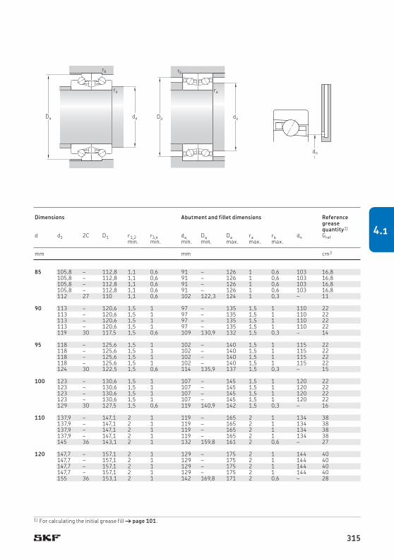
85 130 40,5 33,5 78 3,15 7 300 9 300 1,85 BTM 85 ATN9/P4CDB 85 105,8 – 112,8 1,1 0,6 91 – 126 1 0,6 103 16,8130 40,5 33,5 78 3,15 9 100 10 900 1,7 BTM 85 ATN9/HCP4CDB 105,8 – 112,8 1,1 0,6 91 – 126 1 0,6 103 16,8130 40,5 40 88 3,6 6 400 8 300 1,85 BTM 85 BTN9/P4CDB 105,8 – 112,8 1,1 0,6 91 – 126 1 0,6 103 16,8130 40,5 40 88 3,6 8 000 9 500 1,7 BTM 85 BTN9/HCP4CDB 105,8 – 112,8 1,1 0,6 91 – 126 1 0,6 103 16,8130 54 48,8 146 6,7 5 600 6 700 2,05 BTW 85 CTN9/SP 112 27 110 1,1 0,6 102 122,3 124 1 0,3 – 11
90 140 45 39 91,5 3,55 6 800 8 700 2,45 BTM 90 ATN9/P4CDB 90 113 – 120,6 1,5 1 97 – 135 1,5 1 110 22140 45 39 91,5 3,55 8 500 10 100 2,3 BTM 90 ATN9/HCP4CDB 113 – 120,6 1,5 1 97 – 135 1,5 1 110 22140 45 46,5 102 4 6 000 7 700 2,45 BTM 90 BTN9/P4CDB 113 – 120,6 1,5 1 97 – 135 1,5 1 110 22140 45 46,5 102 4 7 400 8 800 2,3 BTM 90 BTN9/HCP4CDB 113 – 120,6 1,5 1 97 – 135 1,5 1 110 22140 60 55,9 173 7,65 5 000 6 000 2,7 BTW 90 CTN9/SP 119 30 117,5 1,5 0,6 109 130,9 132 1,5 0,3 – 14
95 145 45 40 93 3,6 6 500 8 300 2,55 BTM 95 ATN9/P4CDB 95 118 – 125,6 1,5 1 102 – 140 1,5 1 115 22145 45 40 93 3,6 8 200 9 800 2,4 BTM 95 ATN9/HCP4CDB 118 – 125,6 1,5 1 102 – 140 1,5 1 115 22145 45 46,5 106 4,05 5 800 7 400 2,55 BTM 95 BTN9/P4CDB 118 – 125,6 1,5 1 102 – 140 1,5 1 115 22145 45 46,5 106 4,05 7 200 8 600 2,4 BTM 95 BTN9/HCP4CDB 118 – 125,6 1,5 1 102 – 140 1,5 1 115 22145 60 57,2 180 7,8 5 000 6 000 2,8 BTW 95 CTN9/SP 124 30 122,5 1,5 0,6 114 135,9 137 1,5 0,3 – 15
100 150 45 41,5 102 3,8 6 300 7 900 2,65 BTM 100 ATN9/P4CDB 100 123 – 130,6 1,5 1 107 – 145 1,5 1 120 22150 45 41,5 102 3,8 7 900 9 400 2,5 BTM 100 ATN9/HCP4CDB 123 – 130,6 1,5 1 107 – 145 1,5 1 120 22150 45 48 116 4,3 5 600 7 100 2,65 BTM 100 BTN9/P4CDB 123 – 130,6 1,5 1 107 – 145 1,5 1 120 22150 45 48 116 4,3 6 900 8 200 2,5 BTM 100 BTN9/HCP4CDB 123 – 130,6 1,5 1 107 – 145 1,5 1 120 22150 60 59,2 193 8,15 5 000 6 000 2,95 BTW 100 CTN9/SP 129 30 127,5 1,5 0,6 119 140,9 142 1,5 0,3 – 16
110 170 54 57 137 4,8 5 600 7 100 4,25 BTM 110 ATN9/P4CDB 110 137,9 – 147,1 2 1 119 – 165 2 1 134 38170 54 57 137 4,8 7 000 8 300 3,95 BTM 110 ATN9/HCP4CDB 137,9 – 147,1 2 1 119 – 165 2 1 134 38170 54 65,5 153 5,5 4 900 6 400 4,25 BTM 110 BTN9/P4CDB 137,9 – 147,1 2 1 119 – 165 2 1 134 38170 54 65,5 153 5,5 6 100 7 300 3,95 BTM 110 BTN9/HCP4CDB 137,9 – 147,1 2 1 119 – 165 2 1 134 38170 72 81,9 260 10,4 4 300 5 000 4,7 BTW 110 CTN9/SP 145 36 143,1 2 1 132 159,8 161 2 0,6 – 27
120 180 54 58,5 146 5 5 200 6 700 4,55 BTM 120 ATN9/P4CDB 120 147,7 – 157,1 2 1 129 – 175 2 1 144 40180 54 58,5 146 5 6 500 7 700 4,2 BTM 120 ATN9/HCP4CDB 147,7 – 157,1 2 1 129 – 175 2 1 144 40180 54 69,5 166 5,7 4 600 5 900 4,55 BTM 120 BTN9/P4CDB 147,7 – 157,1 2 1 129 – 175 2 1 144 40180 54 69,5 166 5,7 5 700 6 800 4,2 BTM 120 BTN9/HCP4CDB 147,7 – 157,1 2 1 129 – 175 2 1 144 40180 72 85,2 280 10,8 4 000 4 800 5,05 BTW 120 CTN9/SP 155 36 153,1 2 1 142 169,8 171 2 0,6 – 28
dn
rb
da
ra
Dada
ra
rb
Da
Principal dimensions Basic load ratings Fatigue
load limitAttainable speeds1) Mass Designation Dimensions Abutment and fillet dimensions Reference
grease quantity1)
Grease lubrication
Oil-air lubricationdynamic static
d D H C C0 Pu d d1 2C D1 r1,2 r3,4 da Da Da ra rb dn Grefmin. min. min. min. max. max. max.
mm kN kN r/min kg – mm mm cm3
1) For calculating the initial grease fill † page 101.
315
4.1

130 200 63 73,5 186 6,1 4 700 6 000 6,9 BTM 130 ATN9/P4CDB 130 162,6 – 173,3 2 1 139 – 195 2 1 158 58200 63 73,5 186 6,1 5 900 7 000 6,45 BTM 130 ATN9/HCP4CDB 162,6 – 173,3 2 1 139 – 195 2 1 158 58200 63 85 208 6,8 4 200 5 400 6,9 BTM 130 BTN9/P4CDB 162,6 – 173,3 2 1 139 – 195 2 1 158 58200 63 85 208 6,8 5 100 6 100 6,45 BTM 130 BTN9/HCP4CDB 162,6 – 173,3 2 1 139 – 195 2 1 158 58200 84 106 360 13,2 3 600 4 300 7,6 BTW 130 CTN9/SP 171 42 168,6 2 1 156 187,5 190 2 0,6 – 40
140 210 63 73,5 190 6,1 4 400 5 700 7,85 BTM 140 AM/P4CDB 140 172,6 – 183,3 2,1 1 151 – 205 2,1 1 168 62210 63 73,5 190 6,1 5 600 6 700 7,4 BTM 140 AM/HCP4CDB 172,6 – 183,3 2,1 1 151 – 205 2,1 1 168 62210 63 86,5 216 6,95 3 900 5 100 7,85 BTM 140 BM/P4CDB 172,6 – 183,3 2,1 1 151 – 205 2,1 1 168 62210 63 86,5 216 6,95 4 900 5 800 7,4 BTM 140 BM/HCP4CDB 172,6 – 183,3 2,1 1 151 – 205 2,1 1 168 62210 84 106 375 13,2 3 200 3 800 8,6 BTW 140 CM/SP 181 42 178,6 2,1 1 166 197,7 200 2 0,6 – 45
150 225 67,5 86,5 228 7,1 4 100 5 300 9,6 BTM 150 AM/P4CDB 150 184,9 – 196,4 2,1 1,1 161 – 219 2,1 1 180 80225 67,5 86,5 228 7,1 5 200 6 200 9 BTM 150 AM/HCP4CDB 184,9 – 196,4 2,1 1,1 161 – 219 2,1 1 180 80225 67,5 104 260 8 3 700 4 800 9,6 BTM 150 BM/P4CDB 184,9 – 196,4 2,1 1,1 161 – 219 2,1 1 180 80225 67,5 104 260 8 4 500 5 300 9 BTM 150 BM/HCP4CDB 184,9 – 196,4 2,1 1,1 161 – 219 2,1 1 180 80225 90 127 440 15,3 3 000 3 600 10,5 BTW 150 CM/SP 194 45 191,2 2,1 1 178 212,4 213 2 0,6 – 56
160 240 72 98 260 7,8 3 900 5 000 12 BTM 160 AM/P4CDB 160 196,8 – 209,2 2,1 1,1 171 – 234 2,1 1 192 94240 72 98 260 7,8 4 900 5 800 11 BTM 160 AM/HCP4CDB 196,8 – 209,2 2,1 1,1 171 – 234 2,1 1 192 94240 72 114 290 8,8 3 400 4 500 12 BTM 160 BM/P4CDB 196,8 – 209,2 2,1 1,1 171 – 234 2,1 1 192 94240 72 114 290 8,8 4 300 5 100 11 BTM 160 BM/HCP4CDB 196,8 – 209,2 2,1 1,1 171 – 234 2,1 1 192 94240 96 140 510 16,6 2 800 3 400 13 BTW 160 CM/SP 207 48 203,7 2,1 1 190 226 227 2 0,6 – 67
170 260 81 118 315 9,15 3 600 4 700 16 BTM 170 AM/P4CDB 170 211,3 – 225,6 2,1 1,1 181 – 254 2,1 1 205 126260 81 118 315 9,15 4 500 5 300 15 BTM 170 AM/HCP4CDB 211,3 – 225,6 2,1 1,1 181 – 254 2,1 1 205 126260 81 140 360 10,4 3 200 4 100 16 BTM 170 BM/P4CDB 211,3 – 225,6 2,1 1,1 181 – 254 2,1 1 205 126260 81 140 360 10,4 3 900 4 600 15 BTM 170 BM/HCP4CDB 211,3 – 225,6 2,1 1,1 181 – 254 2,1 1 205 126260 108 174 610 19,6 2 400 3 000 17,5 BTW 170 CM/SP 223 54 219,3 2,1 1 204 244,9 246 2 0,6 – 90
180 280 90 140 365 10,4 3 400 4 400 21,5 BTM 180 AM/P4CDB 226,5 – 241,7 2,1 1,1 191 – 274 2,1 1 220 160280 90 140 365 10,4 4 200 5 000 20 BTM 180 AM/HCP4CDB 180 226,5 – 241,7 2,1 1,1 191 – 274 2,1 1 220 160280 90 163 425 11,8 3 000 3 800 21,5 BTM 180 BM/P4CDB 226,5 – 241,7 2,1 1,1 191 – 274 2,1 1 220 160280 90 163 425 11,8 3 600 4 300 20 BTM 180 BM/HCP4CDB 226,5 – 241,7 2,1 1,1 191 – 274 2,1 1 220 160280 120 199 710 22,4 2 000 2 600 23 BTW 180 CM/SP 239 60 234,8 2,1 1 214 262,6 264 2 0,6 – 117
190 290 120 203 735 22,8 2 000 2 600 24 BTW 190 CM/SP 190 249 60 244,8 2,1 1 224 272,6 274 2 0,6 – 122
200 310 132 238 865 25,5 1 900 2 400 31 BTW 200 CM/SP 200 264 66 259,9 2,1 1 236 291 292 2 0,6 – 157
4.1 Double direction angular contact thrust ball bearingsd 130 – 200 mm
d1
r2
r1
r3r4
H
D1d1
r2
r1
r3r4
d
H
2C
D
BTW BTM
Principal dimensions Basic load ratings Fatigue
load limitAttainable speeds1) Mass Designation Dimensions Abutment and fillet dimensions Reference
grease quantity1)
Grease lubrication
Oilair lubricationdynamic static
d D H C C0 Pu d d1 2C D1 r1,2 r3,4 da Da Da ra rb dn Grefmin. min. min. min. max. max. max.
mm kN kN r/min kg – mm mm cm3
1) Speed values for BTM series bearings are applicable to those with a light preload (suffix DBA). For bearings with a heavy preload ( suffix DBB), attainable speeds are about 75% of the quoted values.
316

130 200 63 73,5 186 6,1 4 700 6 000 6,9 BTM 130 ATN9/P4CDB 130 162,6 – 173,3 2 1 139 – 195 2 1 158 58200 63 73,5 186 6,1 5 900 7 000 6,45 BTM 130 ATN9/HCP4CDB 162,6 – 173,3 2 1 139 – 195 2 1 158 58200 63 85 208 6,8 4 200 5 400 6,9 BTM 130 BTN9/P4CDB 162,6 – 173,3 2 1 139 – 195 2 1 158 58200 63 85 208 6,8 5 100 6 100 6,45 BTM 130 BTN9/HCP4CDB 162,6 – 173,3 2 1 139 – 195 2 1 158 58200 84 106 360 13,2 3 600 4 300 7,6 BTW 130 CTN9/SP 171 42 168,6 2 1 156 187,5 190 2 0,6 – 40
140 210 63 73,5 190 6,1 4 400 5 700 7,85 BTM 140 AM/P4CDB 140 172,6 – 183,3 2,1 1 151 – 205 2,1 1 168 62210 63 73,5 190 6,1 5 600 6 700 7,4 BTM 140 AM/HCP4CDB 172,6 – 183,3 2,1 1 151 – 205 2,1 1 168 62210 63 86,5 216 6,95 3 900 5 100 7,85 BTM 140 BM/P4CDB 172,6 – 183,3 2,1 1 151 – 205 2,1 1 168 62210 63 86,5 216 6,95 4 900 5 800 7,4 BTM 140 BM/HCP4CDB 172,6 – 183,3 2,1 1 151 – 205 2,1 1 168 62210 84 106 375 13,2 3 200 3 800 8,6 BTW 140 CM/SP 181 42 178,6 2,1 1 166 197,7 200 2 0,6 – 45
150 225 67,5 86,5 228 7,1 4 100 5 300 9,6 BTM 150 AM/P4CDB 150 184,9 – 196,4 2,1 1,1 161 – 219 2,1 1 180 80225 67,5 86,5 228 7,1 5 200 6 200 9 BTM 150 AM/HCP4CDB 184,9 – 196,4 2,1 1,1 161 – 219 2,1 1 180 80225 67,5 104 260 8 3 700 4 800 9,6 BTM 150 BM/P4CDB 184,9 – 196,4 2,1 1,1 161 – 219 2,1 1 180 80225 67,5 104 260 8 4 500 5 300 9 BTM 150 BM/HCP4CDB 184,9 – 196,4 2,1 1,1 161 – 219 2,1 1 180 80225 90 127 440 15,3 3 000 3 600 10,5 BTW 150 CM/SP 194 45 191,2 2,1 1 178 212,4 213 2 0,6 – 56
160 240 72 98 260 7,8 3 900 5 000 12 BTM 160 AM/P4CDB 160 196,8 – 209,2 2,1 1,1 171 – 234 2,1 1 192 94240 72 98 260 7,8 4 900 5 800 11 BTM 160 AM/HCP4CDB 196,8 – 209,2 2,1 1,1 171 – 234 2,1 1 192 94240 72 114 290 8,8 3 400 4 500 12 BTM 160 BM/P4CDB 196,8 – 209,2 2,1 1,1 171 – 234 2,1 1 192 94240 72 114 290 8,8 4 300 5 100 11 BTM 160 BM/HCP4CDB 196,8 – 209,2 2,1 1,1 171 – 234 2,1 1 192 94240 96 140 510 16,6 2 800 3 400 13 BTW 160 CM/SP 207 48 203,7 2,1 1 190 226 227 2 0,6 – 67
170 260 81 118 315 9,15 3 600 4 700 16 BTM 170 AM/P4CDB 170 211,3 – 225,6 2,1 1,1 181 – 254 2,1 1 205 126260 81 118 315 9,15 4 500 5 300 15 BTM 170 AM/HCP4CDB 211,3 – 225,6 2,1 1,1 181 – 254 2,1 1 205 126260 81 140 360 10,4 3 200 4 100 16 BTM 170 BM/P4CDB 211,3 – 225,6 2,1 1,1 181 – 254 2,1 1 205 126260 81 140 360 10,4 3 900 4 600 15 BTM 170 BM/HCP4CDB 211,3 – 225,6 2,1 1,1 181 – 254 2,1 1 205 126260 108 174 610 19,6 2 400 3 000 17,5 BTW 170 CM/SP 223 54 219,3 2,1 1 204 244,9 246 2 0,6 – 90
180 280 90 140 365 10,4 3 400 4 400 21,5 BTM 180 AM/P4CDB 226,5 – 241,7 2,1 1,1 191 – 274 2,1 1 220 160280 90 140 365 10,4 4 200 5 000 20 BTM 180 AM/HCP4CDB 180 226,5 – 241,7 2,1 1,1 191 – 274 2,1 1 220 160280 90 163 425 11,8 3 000 3 800 21,5 BTM 180 BM/P4CDB 226,5 – 241,7 2,1 1,1 191 – 274 2,1 1 220 160280 90 163 425 11,8 3 600 4 300 20 BTM 180 BM/HCP4CDB 226,5 – 241,7 2,1 1,1 191 – 274 2,1 1 220 160280 120 199 710 22,4 2 000 2 600 23 BTW 180 CM/SP 239 60 234,8 2,1 1 214 262,6 264 2 0,6 – 117
190 290 120 203 735 22,8 2 000 2 600 24 BTW 190 CM/SP 190 249 60 244,8 2,1 1 224 272,6 274 2 0,6 – 122
200 310 132 238 865 25,5 1 900 2 400 31 BTW 200 CM/SP 200 264 66 259,9 2,1 1 236 291 292 2 0,6 – 157
dn
rb
da
ra
Dada
ra
rb
Da
Principal dimensions Basic load ratings Fatigue
load limitAttainable speeds1) Mass Designation Dimensions Abutment and fillet dimensions Reference
grease quantity1)
Grease lubrication
Oil-air lubricationdynamic static
d D H C C0 Pu d d1 2C D1 r1,2 r3,4 da Da Da ra rb dn Grefmin. min. min. min. max. max. max.
mm kN kN r/min kg – mm mm cm3
1) For calculating the initial grease fill † page 101.
317
4.1


Product table5.1 Axial-radial cylindrical roller
bearings . . . . . . . . . . . . . . . . . . . . . . 334
Designs and variants . . . . . . . . . . . . . . 320
Bearing data . . . . . . . . . . . . . . . . . . . . . 321(Boundary dimensions, tolerances)
Preload and stiffness . . . . . . . . . . . . . . 322
Friction . . . . . . . . . . . . . . . . . . . . . . . . . . 322
Lubrication . . . . . . . . . . . . . . . . . . . . . . . 324
Design considerations . . . . . . . . . . . . . . 324
Load carrying capacity . . . . . . . . . . . . . 327
Equivalent bearing loads . . . . . . . . . . . 327
Permissible moment load . . . . . . . . . . . 328
Mounting . . . . . . . . . . . . . . . . . . . . . . . . 330
Designation system . . . . . . . . . . . . . . . . 333
Axial-radial cylindrical roller bearings
More informationBearing life and load ratings . . . . . . . . 33Requisite minimum load . . . . . . . . . . . 34Chamfer dimension limits . . . . . . . . . . 47Materials . . . . . . . . . . . . . . . . . . . . . . . 51Design considerations . . . . . . . . . . . . . 57Lubrication . . . . . . . . . . . . . . . . . . . . . 99Mounting and dismounting . . . . . . . . . 123Bearing storage . . . . . . . . . . . . . . . . . . 125
319
5

Axial-radial cylindrical roller bearings
Super-precision axial-radial cylindrical roller bearings are commonly used to support rotary tables, indexing heads and multi-spindle heads on machining centres. SKF manufactures super-precision axial-radial cylindrical roller bearings for shaft diameters from 80 to 850 mm. Their internal design, together with close tolerance manufacturing processes, en ables these bearings to attain radial run-out better than, and axial run-out close to, P4 tol-erance class.
Designs and variants Axial-radial cylindrical roller bearings can accommodate radial loads, axial loads in both directions and moment loads, whether acting singly, or simultaneously, in any combination.
These bearings consist of († fig. 1):
• Two roller and cage thrust assemblies and a full complement radial roller set.
• An inner ring which has an L-shaped cross section and two raceways. One raceway accommodates the roller and cage thrust assembly and the other accommodates the full complement radial roller set. The inner ring is drilled for attachment bolts.
• A loose flange which acts as a raceway to accommodate the second roller and cage thrust assembly. The flange is held in place to the inner ring with transport bolts that should not be removed until after the bear-ing has been mounted. The flange is drilled for attachment bolts.
• An outer ring which has three raceways to accommodate both roller and cage thrust assemblies and the full complement radial roller set.
The bearings are supplied standard without grease (no designation suffix) but can also be supplied greased (designation suffix G).
Bearings supplied without grease must be adequately lubricated with either grease or oil through the lubrication holes in the bearing rings. Bearings, greased at the factory, are filled with a grease that is suitable for most applications over the normal speed range for the bearing.
Fig. 1
320

Bearing data
Bearing dataBoundary dimensions
Not standardized
TolerancesFor additional information († page 47)
• manufactured to the tolerances listed in table 1• improved radial and axial run-out (50% tighter) on request
Table 1
Tolerances for axial-radial cylindrical roller bearings
Inner ring
d Δds Vdp Vdmp ΔHs ΔH1s Kia Siover incl. high low max. max. high low high low max. max.
mm µm µm µm µm µm µm µm
50 80 0 –9 5 3,5 0 –175 25 –25 3 380 120 0 –10 6 4 0 –175 25 –25 3 3120 150 0 –13 8 5 0 –175 30 –30 3 3
150 180 0 –13 8 5 0 –175 30 –30 4 4180 250 0 –15 9 6 0 –200 30 –30 4 4250 315 0 –18 11 8 0 –400 40 –40 6 6
315 400 0 –23 14 10 0 –400 50 –50 6 6400 500 0 –27 17 12 0 –450 60 –60 6 6500 630 0 –33 20 14 0 –500 75 –75 10 10
630 800 0 –40 24 16 0 –700 100 –100 10 10800 1 000 0 –50 30 20 0 –850 120 –120 12 12
Outer ring
D ΔDs VDp VDmp Kea Seover incl. high low max. max. max. max.
mm µm µm µm
120 150 0 –11 7 5 Values are identical to those for inner ring of the same bearing.
150 180 0 –13 8 5180 250 0 –15 8 6
250 315 0 –18 10 7315 400 0 –20 11 8400 500 0 –23 14 9
500 630 0 –28 17 11630 800 0 –35 20 13800 1 000 0 –45 26 171 000 1 250 0 –55 34 20
Tolerance symbols and definitions † table 4, page 48
321
5

Axial-radial cylindrical roller bearings
Preload and stiffnessDue to the large number of cylindrical rollers in each of the rows, with line contact between them and the raceways, there is a minimal amount of elastic deformation in the bearing under load from any direction.
To provide maximum stiffness the rollers are calibrated during assembly so that a preload is achieved in each row once mounting is complete. Appropriate preload extends bear-ing service life, improves rigidity and running accuracy, while reducing noise levels.
As a result of the closely controlled preload, stiffness in any direction can be considered constant.
In cases where a heavy axial load acts on an axial-radial cylindrical roller bearing, the loaded roller set can deflect and reduce the preload on the second thrust roller set. In severe cases, the second thrust roller set can become completely unloaded, which can cause the rollers to skid and damage the raceways or subject the cage to impermissible stresses. For additional information, contact the SKF appli-cation engineering service.
Preload for the thrust roller sets and stiff-ness values, together with the axial unloading force, are listed in table 2. They are valid for bearings mounted properly and attachment bolts tightened to the recommended torque values († table 7, page 332).
FrictionThe frictional losses in axial-radial cylindrical roller bearings, as with other rolling bearings, depend on different factors. For general infor-mation, refer to Friction († page 37).
The values for the frictional moment listed in table 3 were measured in functional tests and are average values. They should be used as guideline values only. The tests were con-ducted under the following operating conditions:
• lubrication: grease, kinematic viscosity 150 mm2/s at 40 °C (105 °F)
• rotational speed: 5 r/min• ambient temperature: 30 to 40 °C (85 to
105 °F)• attachment bolts tightened to the recom-
mended torque values († table 7, page 332)
322

Friction
Table 2
Preload and stiffness
Bearing Axial preload1) Axial unloading force1)
Axial stiffness2) Radial stiffness2) Tilting stiffness2)
– kN kN kN/µm kN/µm kNm/mrad
NRT 80 A 1,3 2,8 4,9 3,1 7 NRT 100 A 1,7 3,8 7,2 3,7 15 NRT 120 A 1,9 4,3 8,1 4,5 22
NRT 150 A 2,2 4,8 9 5,5 35 NRT 180 A 2,5 5,5 10,3 5,8 53 NRT 200 A 2,8 6,2 11,6 6,5 73
NRT 260 A 7,2 16 14,5 8,3 150 NRT 325 A 12 26 28,6 8,9 413 NRT 395 A 14 30 33,6 10,6 672
NRT 460 A 16 34 38,5 12,1 1 036 NRT 580 A 25 55 43,5 18,6 1 838 NRT 650 A 27 59 60 17,2 3 209 NRT 850 A 47 103 77 22,4 7 011
1) These values are averages.2) Stiffness values refer to the roller set.
Table 3
Frictional moment
Bearing Frictional momentCRL
– Nm
NRT 80 A 3 NRT 100 A 3 NRT 120 A 6
NRT 150 A 12 NRT 180 A 13 NRT 200 A 14
NRT 260 A 25 NRT 325 A 45 NRT 395 A 55
NRT 460 A 70 NRT 580 A 140 NRT 650 A 200 NRT 850 A 300
Guideline values only
323
5

Axial-radial cylindrical roller bearings
LubricationThe choice of whether to use grease or oil should be based on the speed and operating temperature of the application. Axial-radial cylindrical roller bearings are typically lubri-cated by an oil bath or circulating oil system. Grease is normally reserved for slower speed and lower temperature applications.
Grease or oil can be introduced into the bearing via the lubrication holes in the bearing rings. Note that if the bearing is over-lubri-cated, excessive frictional heat increases bear-ing operating temperature.
The technical specifications of the standard grease in greased axial-radial cylindrical roller bearings (designation suffix G) are listed in table 4.
To achieve the lowest frictional moment and temperature, axial-radial cylindrical roller bearings need to be properly run-in. A typical running-in procedure consists of rotating the bearing for one hour at different speed steps, starting from an initial value of ~ 15% of the maximum operating speed and increasing by steps of 10% each time. During running-in, the bearing operating temperature should not exceed 70 °C (160 °F).
Table 4
Technical specifications of the standard grease in greased bearings (designation suffix G)
Properties Grease specification
Thickener Lithium complex soap
Base oil type Mineral
NLGI consistency class 2
Temperature range[°C] –30 to +140[°F] –20 to +285
Kinematic viscosity [mm2/s]at 40 °C (105 °F) 185at 100 °C (210 °F) 15
Design considerationsRecommended shaft and housing fitsShaft and housing seats for super-precision axial-radial cylindrical roller bearings should be manufactured to the following tolerance classes:
• h5VE for the shaft († table 5)• J6VE for the housing bore († table 6,
page 326)
Accuracy of seats and abutmentsIf a super-precision axial-radial cylindrical roller bearing is to obtain a high degree of run-ning accuracy and low operating temperature, its associated components must be manufac-tured to similar levels of precision.
Recommendations for the geometrical toler-ances and surface roughness are provided in:
• table 5 for the shaft• table 6, page 326 for the housing
The recommended shaft and housing diameter tolerances, relative to the bearing bore and outside diameter tolerances result in a transi-tion fit, tending towards clearance. In some cases, however, an interference fit may result for either the bearing inner or outer ring. When this occurs, preload on the radial roller set will increase, as will contact stresses, friction and frictional heat.
To optimize operating conditions and run-ning accuracy in applications where there is inner ring rotation, the fit between the shaft and inner ring should be a loose fit that is as close to zero as possible. A near-zero loose fit should be applied to the outer ring and housing when the outer ring rotates.
To help obtain a near-zero loose fit on a shaft, SKF supplies axial-radial cylindrical roller bearings with an inspection report. The report includes the measured deviation from nominal of the inner ring bore diameter. It also includes the measured deviation from nominal of the bearing height and measured running accuracy.
324

Design considerations
Table 5
Geometrical accuracy for bearing shaft seats
Shaft diameter Tolerance Total radial run-out
Total axial run-out
Surface roughness
da h5VE ra t1 t5 Raover incl. high low max. max. max. max.
mm µm mm µm µm µm
50 80 0 –13 0,2 3 3 0,8 80 120 0 –15 0,2 4 4 0,8 120 150 0 –18 0,2 5 5 0,8
150 180 0 –18 0,2 5 5 0,8 180 250 0 –20 0,2 7 7 0,8 250 315 0 –23 0,5 8 8 0,8
315 400 0 –25 0,5 9 9 0,8 400 500 0 –27 0,9 10 10 0,8 500 630 0 –32 0,9 11 11 0,8
630 800 0 –36 1,3 13 13 0,8 800 1 000 0 –40 1,3 15 15 0,8
Ct5Ct1
da
Ra
Ra
ra
C
Surface roughness Ra in accordance with ISO 1302
325
5

Axial-radial cylindrical roller bearings
Table 6
Geometrical accuracy for bearing housing seats
Housing diameter Tolerance Total radial run-out
Total axial run-out
Surface roughness
Da J6VE ra t1 t5 Raover incl. high low max. max. max. max.
mm µm mm µm µm µm
120 150 18 –7 0,2 5 5 0,8 150 180 18 –7 0,5 5 5 0,8 180 250 22 –7 0,5 7 7 0,8
250 315 25 –7 0,5 8 8 0,8 315 400 29 –7 0,5 9 9 0,8 400 500 33 –7 0,5 10 10 0,8
500 630 34 –10 0,9 11 11 0,8 630 800 38 –12 0,9 13 13 0,8 800 1 000 44 –12 0,9 15 15 0,8
1 000 1 250 52 –14 1,3 18 18 0,8
Bt5Bt1
Da
Ra
Rara
B
Surface roughness Ra in accordance with ISO 1302
326

Equivalent bearing loads
Load carrying capacityAxial-radial cylindrical roller bearings can accommodate radial loads, axial loads in both directions and moment loads, whether acting singly, or simultaneously, in any combination. As the bearing is preloaded and normally used to support axial and radial loads acting offset from, or eccentrically to, the bearing axis, the evaluation of the equivalent bearing loads by manual methods can only be approximated. Equivalent bearing loads in the radial and axial directions should be calculated separately. From these, the life ratings can be calculated for each row of rollers. If a more accurate bearing load analysis and and calculation for rated life are required, contact the SKF appli-cation engineering service.
Basic load ratings are listed in the product table († page 334).
Equivalent bearing loads The equivalent dynamic bearing load can be calculated:
• for the radial roller set usingP = Fr
• for the thrust roller set usingP = Fa + 4,4 M/d1
The equivalent static bearing load can be calculated:
• for the radial roller set usingP0 = Fr
• for the thrust roller set usingP0 = Fa + 4,4 M/d1
whereP = equivalent dynamic bearing load [kN]P0 = equivalent static bearing load [kN]d1 = outside diameter of inner ring [mm]
(† product table, page 334)Fa = axial load [kN] Fr = radial load [kN]M = moment load [kNmm]
327
5

Axial-radial cylindrical roller bearings
Permissible moment loadAxial-radial cylindrical roller bearings gener-ally rotate slowly, perform slow slewing move-ments, or are subjected to load when station-ary. Under these conditions, the maximum permissible moment load is limited by the static load limit and can be determined using
Mperm = 0,23 d1 (C0a/s0 – Fa)
whereMperm = permissible moment [kNmm]C0a = basic static load rating of thrust roller
set [kN] († product table, page 334)
d1 = outside diameter of inner ring [mm] († product table)
Fa = centrically acting axial load [kN] s0 = safety factor († Permissible static
loads, page 36) = 4
If frequent rotation or oscillation apply, rating life may limit the permissible moment load. In these cases, contact the SKF application en gin-eer ing service.
Diagram 1 can be used for a quick check of the suitability of the selected bearing size under predominantly static loads.
328
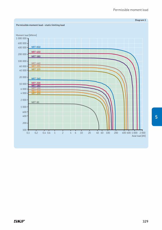
Permissible moment load
0,1 10,2 0,4 0,6 2 4 6 10 20 40 60 100 200 400 600 1 000 2 000
1 000 000
100 000
10 000
1 000
400
600
6 000
200
100
2 000
60 000
4 000
20 000
600 000
40 000
200 000
400 000
Axial load [kN]
NRT 260
NRT 200NRT 180NRT 150NRT 120NRT 100
NRT 850
NRT 650
NRT 580
NRT 460NRT 395NRT 325
NRT 80
Moment load [kNmm]
Diagram 1
Permissible moment load – static limiting load
329
5

Axial-radial cylindrical roller bearings
MountingAxial-radial cylindrical roller bearings are pre-cision machine elements that can provide long service life, provided they are mounted and maintained properly. Proper mounting requires experience, accuracy, a clean work environment and the appropriate tools.
Mounting instructionsFor general information about mounting bear-ings, refer to Mounting and dismounting († page 123).
When mounting axial-radial cylindrical roller bearings the inner ring can be unsupported († fig. 2) or supported († fig. 3). When a support ring is used, it should support the inner ring over its entire width. The support ring should be approximately twice the thick-ness of the flange.
CAUTION: To reduce the risk of damaging the bearing, do not apply any force through the rolling elements. Force should only be applied directly through the ring that is being mounted.
Mounting procedure1 Coat all mating surfaces on the shaft and
inner ring with a thin layer of light oil.2 Loosen the retaining bolts (used to secure
the bearing during transportation) 1/2 a turn.
3 Mount the bearing onto the shaft, loose flange first, aligning the attachment bolt holes in the bearing with the tapped holes in the shaft. To facilitate this process, an induc-tion heater can be used and/or a guide stud can be inserted into one of the attachment bolt holes in the shaft. SKF does not recom-mend heating axial-radial cylindrical roller bearings above 80 °C (175 °F).
4 Once the bearing (and support ring where applicable) is in position against the shaft abutment and the assembly is at ambient temperature, insert the attachment bolts and tighten them “finger tight” while rotat-ing the outer ring. This procedure helps to settle the rollers and centre the inner ring assembly.
5 With the inner ring centred, gradually tighten each attachment bolt in a criss-cross pattern in three stages († fig. 4), tightening the bolts to 35%, then 70% and then 100% of the recommended torque values listed in table 7 († page 332).
6 After the bearing is fitted, the retaining bolts must not be left loose. Either retighten them to the recommended torque values or remove them completely.
7 A similar procedure can be applied for fitting the outer ring. Coat all mating surfaces in the housing and on the outer ring with a thin layer of light oil.
8 Mount the bearing/shaft assembly into the housing († fig. 5).
9 Insert and tighten the attachment bolts “fin-ger tight” while rotating the bearing/shaft assembly. Tighten each attachment bolt in a criss-cross pattern in three stages († fig. 6), as described in step 5.
Checking running accuracy and frictionOnce mounting is complete, the running ac-curacy and friction need to be checked. In cases where friction is particularly high, there are three potential explanations:
• The mating parts are not machined accord-ing to specification.
• The attachment bolts are over-tightened.• There is too much grease in the bearing.
To eliminate possible stresses that may have occurred during mounting, loosen all attach-ment bolts and retighten them in a criss-cross pattern using the three stage process described above.
Storage/TransportAxial-radial cylindrical roller bearings should always be stored flat.
330

Mounting
Fig. 2
Fig. 4
Fig. 6
Fig. 3
Fig. 5
331
5

Axial-radial cylindrical roller bearings
Table 7
Bolt tightening torque
Bearing Tightening torqueBolt quality 10,9
– Nm
NRT 80 A 8,5 NRT 100 A 8,5 NRT 120 A 14
NRT 150 A 14 NRT 180 A 14 NRT 200 A 14
NRT 260 A 34 NRT 325 A 34 NRT 395 A 34
NRT 460 A 34 NRT 580 A 68 NRT 650 A 116 NRT 850 A 284
Do not use a higher torque value which could increase the bearing preload.
332

Designation system
Designation system
Bearing series
NRT Axial-radial cylindrical roller bearing
Bearing size
80 Bore diameter [mm]to850
Internal design
A Basic internal designB Modified internal design
Other features
G Bearing greased at the factory
Example: NRT 260 A/G NRT 260 A / G
333
5

80 146 35 23,35 12 130 0,3 0,3 55 102 37,5 200 350 700 2,4 200 NRT 80 A 92 5,6 102) 4 12 3 138 4,6 12 M5 3 12x30 M5
100 185 38 25 12 160 0,6 0,3 58,3 116 68 390 280 560 4,1 260 NRT 100 A 112 5,6 10 5,4 16 2 170 5,6 15 M5 3 18x20 M5
120 210 40 26 12 184 0,6 0,3 64,4 140 72 440 230 460 5,3 315 NRT 120 A 135 7 11 6,2 22 2 195 7 21 M8 3 24x15 M6
150 240 40 26 12 214 0,6 0,3 67,1 160 75 480 210 420 6,2 350 NRT 150 A 165 7 11 6,2 34 2 225 7 33 M8 3 36x10 M6
180 280 43 29 15 244 0,6 0,3 89,7 236 80 560 190 380 7,7 400 NRT 180 A 194 7 11 6,2 46 2 260 7 45 M8 3 48x7,5 M6
200 300 45 30 15 274 0,6 0,3 93,5 270 85 630 170 340 9,7 500 NRT 200 A 215 7 11 6,2 46 2 285 7 45 M8 3 48x7,5 M6
260 385 55 36,5 18 345 0,6 0,6 108 355 95 780 130 260 18,5 630 NRT 260 A 280 9,3 15 8,2 34 2 365 9,3 33 M12 3 36x10 M8
325 450 60 40 20 415 0,6 0,6 134 450 153 1 660 110 220 25 700 NRT 325 A 342 9,3 152) 8,2 34 2 430 9,3 33 M12 3 36x10 M8
395 525 65 42,5 20 486 1 1 147 530 166 1 960 90 180 33 800 NRT 395 A 415 9,3 15 8,2 46 2 505 9,3 45 M12 3 48x7,5 M8
460 600 70 46 22 560 1 1 201 765 180 2 240 80 160 45 1 000 NRT 460 A 482 9,3 15 8,2 46 2 580 9,3 45 M12 3 48x7,5 M8
580 750 90 60 30 700 1 1 229 965 285 3 550 60 120 89 1 250 NRT 580 A 610 11,4 18 11 46 2 720 11,4 42 M12 6 48x7,5 M10
650 870 122 78 34 800 1 1 413 1 600 365 5 000 55 110 170 1 450 NRT 650 A 680 14 20 13 46 2 830 14 42 M12 6 48x7,5 M12
850 1 095 124 80,5 37 1 018 1,5 1,5 473 2 120 415 6 400 40 80 253 1 800 NRT 850 A 890 18 26 17 58 2 1 055 18 54 M16 6 60x6 M16
r1
r1
N1N2
d
Dd1
J1
J
r2
r2
N
CHH1
a
Principal dimensions Basic load ratings Limiting speeds Mass Suit-
able ro tary table
Designa-tion
Attachment holesradial axial Grease
lubri-cation
Oil lubri-cation
Inner ring Outer ring Pitch Retaining bolt threaddynamic static dynamic static Attachment
holesRetaining bolts1)
Attachment holes
Removal thread
Removal threadd1) D H H1 C d1 r1 r2 C C0 C C0 J N N1 a J1 N2
min. min. nr. nr. nr. G nr. nr. x a [°]
mm kN r/min kg mm – mm – mm – – –
5.1 Axial-radial cylindrical roller bearingsd 80 – 850 mm
1) Different shaft diameters can be supplied on request. Contact your local SKF representative.
334

80 146 35 23,35 12 130 0,3 0,3 55 102 37,5 200 350 700 2,4 200 NRT 80 A 92 5,6 102) 4 12 3 138 4,6 12 M5 3 12x30 M5
100 185 38 25 12 160 0,6 0,3 58,3 116 68 390 280 560 4,1 260 NRT 100 A 112 5,6 10 5,4 16 2 170 5,6 15 M5 3 18x20 M5
120 210 40 26 12 184 0,6 0,3 64,4 140 72 440 230 460 5,3 315 NRT 120 A 135 7 11 6,2 22 2 195 7 21 M8 3 24x15 M6
150 240 40 26 12 214 0,6 0,3 67,1 160 75 480 210 420 6,2 350 NRT 150 A 165 7 11 6,2 34 2 225 7 33 M8 3 36x10 M6
180 280 43 29 15 244 0,6 0,3 89,7 236 80 560 190 380 7,7 400 NRT 180 A 194 7 11 6,2 46 2 260 7 45 M8 3 48x7,5 M6
200 300 45 30 15 274 0,6 0,3 93,5 270 85 630 170 340 9,7 500 NRT 200 A 215 7 11 6,2 46 2 285 7 45 M8 3 48x7,5 M6
260 385 55 36,5 18 345 0,6 0,6 108 355 95 780 130 260 18,5 630 NRT 260 A 280 9,3 15 8,2 34 2 365 9,3 33 M12 3 36x10 M8
325 450 60 40 20 415 0,6 0,6 134 450 153 1 660 110 220 25 700 NRT 325 A 342 9,3 152) 8,2 34 2 430 9,3 33 M12 3 36x10 M8
395 525 65 42,5 20 486 1 1 147 530 166 1 960 90 180 33 800 NRT 395 A 415 9,3 15 8,2 46 2 505 9,3 45 M12 3 48x7,5 M8
460 600 70 46 22 560 1 1 201 765 180 2 240 80 160 45 1 000 NRT 460 A 482 9,3 15 8,2 46 2 580 9,3 45 M12 3 48x7,5 M8
580 750 90 60 30 700 1 1 229 965 285 3 550 60 120 89 1 250 NRT 580 A 610 11,4 18 11 46 2 720 11,4 42 M12 6 48x7,5 M10
650 870 122 78 34 800 1 1 413 1 600 365 5 000 55 110 170 1 450 NRT 650 A 680 14 20 13 46 2 830 14 42 M12 6 48x7,5 M12
850 1 095 124 80,5 37 1 018 1,5 1,5 473 2 120 415 6 400 40 80 253 1 800 NRT 850 A 890 18 26 17 58 2 1 055 18 54 M16 6 60x6 M16
a
N2G ×
3
Principal dimensions Basic load ratings Limiting speeds Mass Suit-
able ro tary table
Designa-tion
Attachment holesradial axial Grease
lubri-cation
Oil lubri-cation
Inner ring Outer ring Pitch Retaining bolt threaddynamic static dynamic static Attachment
holesRetaining bolts1)
Attachment holes
Removal thread
Removal threadd1) D H H1 C d1 r1 r2 C C0 C C0 J N N1 a J1 N2
min. min. nr. nr. nr. G nr. nr. x a [°]
mm kN r/min kg mm – mm – mm – – –
1) Retaining bolts are screwed into the loose flange.2) Milled slots open towards bearing bore.
335
5.1

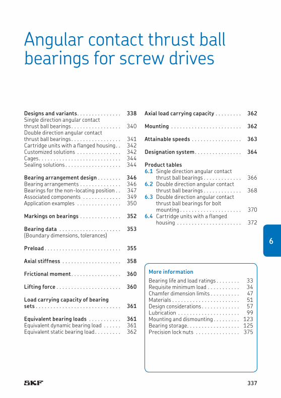
Product tables6.1 Single direction angular contact
thrust ball bearings . . . . . . . . . . . . . 3666.2 Double direction angular contact
thrust ball bearings . . . . . . . . . . . . . 3686.3 Double direction angular contact
thrust ball bearings for bolt mounting . . . . . . . . . . . . . . . . . . . . . 370
6.4 Cartridge units with a flanged housing . . . . . . . . . . . . . . . . . . . . . . 372
Designs and variants . . . . . . . . . . . . . . . 338Single direction angular contact thrust ball bearings . . . . . . . . . . . . . . . . . 340Double direction angular contact thrust ball bearings . . . . . . . . . . . . . . . . . 341Cartridge units with a flanged housing . . 342Customized solutions . . . . . . . . . . . . . . . 342Cages . . . . . . . . . . . . . . . . . . . . . . . . . . . . 344Sealing solutions . . . . . . . . . . . . . . . . . . . 344
Bearing arrangement design . . . . . . . . 346Bearing arrangements . . . . . . . . . . . . . . 346Bearings for the non-locating position . . 347Associated components . . . . . . . . . . . . . 349Application examples . . . . . . . . . . . . . . . 350
Markings on bearings . . . . . . . . . . . . . . 352
Bearing data . . . . . . . . . . . . . . . . . . . . . 353(Boundary dimensions, tolerances)
Preload . . . . . . . . . . . . . . . . . . . . . . . . . . 355
Axial stiffness . . . . . . . . . . . . . . . . . . . . 358
Frictional moment . . . . . . . . . . . . . . . . . 360
Lifting force . . . . . . . . . . . . . . . . . . . . . . 360
Load carrying capacity of bearing sets . . . . . . . . . . . . . . . . . . . . . . . . . . . . . 361
Equivalent bearing loads . . . . . . . . . . . 361Equivalent dynamic bearing load . . . . . . 361Equivalent static bearing load . . . . . . . . . 362
More informationBearing life and load ratings . . . . . . . . 33Requisite minimum load . . . . . . . . . . . 34Chamfer dimension limits . . . . . . . . . . 47Materials . . . . . . . . . . . . . . . . . . . . . . . 51Design considerations . . . . . . . . . . . . . 57Lubrication . . . . . . . . . . . . . . . . . . . . . 99Mounting and dismounting . . . . . . . . . 123Bearing storage . . . . . . . . . . . . . . . . . . 125Precision lock nuts . . . . . . . . . . . . . . . 375
Axial load carrying capacity . . . . . . . . . 362
Mounting . . . . . . . . . . . . . . . . . . . . . . . . 362
Attainable speeds . . . . . . . . . . . . . . . . . 363
Designation system . . . . . . . . . . . . . . . . 364
Angular contact thrust ball bearings for screw drives
337
6

Angular contact thrust ball bearings for screw drives
Machine tools require screw drives that can position a work piece or machine component quickly, efficiently, and precisely. To meet these requirements, screw drives can be supported at both ends by SKF super-precision angular contact thrust ball bearings. The bearings pro-vide a high degree of axial stiffness, high axial load carrying capacity, accommodate high speeds and rapid accelerations, and offer very high running accuracy.
Angular contact thrust ball bearings for screw drives are well suited for screw drive applications, but are also beneficial in other applications, where safe radial and axial sup-port is required, together with extremely pre-cise axial guidance of the shaft.
Designs and variantsThe SKF assortment of super-precision angu-lar contact thrust ball bearings for screw drives can accommodate virtually any requirement placed on support bearings for screw drives. SKF supplies three types of support bearings:
• single direction bearings• double direction bearings• cartridge units with a flanged housing
The main criteria used when selecting bear-ings to support screw drives are axial stiffness and load carrying capacity, running accuracy, speed, and frictional moment. Other factors to consider can be the moment stiffness of a bearing arrangement or the ability to cope with misalignment between the shaft and housing. Mounting and seal requirements also need to be considered. Table 1 provides an overview of the criteria and to what extent the different bearing series fulfil the requirements.
338

Designs and variants
Symbols: ++ very good + good o suitable
Table 1
Selection criteria for angular contact thrust ball bearings for screw drives
Bearing type Single direction bearings
Double direction bearings
Double direction bearings for bolt mounting
Cartridge units
Bearing series BSA, BSD BEAS BEAM FBSA
Selection criteria
Axial stiffness ++ + + ++
Axial load carrying capacity ++ ++ ++ ++
Running accuracy ++ ++ ++ ++
Speed capability ++ + + +
Frictional moment ++ + + ++
Flexibility in arrangement + o o ++
Easy mounting o + ++ ++
Seals non-contact seals (optional)
contact or non-contact seals
contact or non-contact seals
laminar rings
339
6

Angular contact thrust ball bearings for screw drives
Single direction angular contact thrust ball bearingsSKF supplies single direction angular contact thrust ball bearings († fig. 1) in the BSA and BSD series for shaft diameters from 12 to 75 mm. The bearings are non-separable and have a 62° contact angle. The transition radius between the raceway and shoulder on both rings is ground. This reduces edge stresses by approximately 30%, enabling these bearings to accommodate heavy axial loads and incidental overloading better than conventional designs.
Single direction bearings are designed to accommodate axial loads in one direction only and are therefore adjusted against a second bearing or mounted as sets. The bearings are universally matchable, as standard, and can be mounted in sets of up to four bearings for a variety of bearing arrangements, reaching the performance level of matched sets. A unique heat treatment helps to maintain a constant bearing preload over the entire service life of the bearings.
Matched bearing setsSingle direction bearings can be supplied as matched sets on request. However, because the standard bearings are universally match-able, SKF recommends reducing inventory by ordering single bearings only and arranging them in sets as required.
Fig. 1
340

Designs and variants
Double direction angular contact thrust ball bearingsDouble direction angular contact thrust ball bearings were developed for applications where space is limited and easy mounting is required. SKF double direction bearings are greased and sealed as standard. These ready-to-mount bearings are available in two series:
• double direction bearings in the BEAS series († fig. 2), for shaft diameters from 8 to 30 mm
• double direction bearings for bolt mounting in the BEAM series († fig. 3), for shaft diameters from 12 to 60 mm
Bearings in the BEAS series correspond in design to two single direction bearings arranged back-to-back. They are non-sep ar-able and have a one-piece outer ring, a two-piece inner ring, and a 60° contact angle. The bearings accommodate radial loads, and axial loads in both directions. Preload (which is pre-set at the factory) is applied by clamping the inner ring halves on the screw drive shaft with, for example, a precision lock nut († Precision lock nuts, page 375). The bearings have an annular groove and lubrication holes in the outer ring as standard to relubricate the bear-ing easily and reliably when necessary.
Bearings in the BEAM series correspond in design to BEAS series bearings except that the outer ring is much thicker and equipped with through holes for attachment bolts. By bolting directly onto an associated component, the
design and mounting process is simplified. To enable relubrication, if required, one side face and the bearing outside surface have M6 threaded holes for grease fittings. The holes are plugged on delivery with grub (set) screws. The side face with the threaded hole should be mounted opposite the machine wall. Bearings manufactured to larger tolerances (designation suffix PE) do not have a threaded hole on the outside surface of the bearing and can only be relubricated via the threaded hole in the side face.
BEAM bearings have an annular groove on their outside surface that can be used to dis-mount the bearing from its seat on the screw drive shaft.
Fig. 2 Fig. 3
341
6

Angular contact thrust ball bearings for screw drives
Cartridge units with a flanged housingCartridge units in the FBSA series († fig. 4) have a flanged housing to enable quick and easy mounting. These ready-to-mount units are available for shaft diameters ranging from 20 to 60 mm and incorporate SKF single direc-tion angular contact thrust ball bearings († Single direction angular contact thrust ball bearings, page 340). Except for the ground surfaces, the units are surface-treated with a black-oxide finish.
The units are available with different bear-ing arrangements († fig. 5):
• two bearings arranged back-to-back, desig-nation suffix DB
• two bearings arranged face-to-face, desig-nation suffix DF
• two bearing pairs arranged tandem back-to-back, designation suffix QBC
• two bearing pairs arranged tandem face-to-face, designation suffix QFC
Units with two bearing pairs are also available with the flange at the end of the cartridge (designation suffix A). Other bearing arrange-ments are available on request.
Cartridge units should be bolted to the machine wall and located on the screw drive shaft with an SKF precision lock nut († Precision lock nuts, page 375).
Customized solutionsThe SKF assortment of support bearings covers a wide variety of application conditions. SKF can also provide customized solutions for specific applications. Advanced modelling and virtual testing services enable SKF engineers to assist in all stages of product development. Contact the application engineering service for additional information.
Greased bearingsOpen, single direction bearings can be supplied greased on request, with the standard grease used for sealed bearings (designation suffix GMM, † Sealing solutions, page 344). Cus-tomer-specific greases or fill quantities can also be applied to meet the requirements of a specific application.
342

Designs and variants
DB DF
QBC QFC
Fig. 5
Fig. 4
FBSA2.. /DB FBSA 2.. /QBC FBSA 2.. A/QBC
343
6

Angular contact thrust ball bearings for screw drives
CagesDepending on their series, angular contact thrust ball bearings for screw drives are fitted as standard with one of the following cages:
• a glass fibre reinforced PA66 cage, window-type, ball centred, no designation suffix
• a glass fibre reinforced PA66 cage, snap-type, ball centred, no designation suffix
These robust cages are extremely light to min-imize centrifugal forces and accommodate high accelerations and decelerations.
For additional information about the materi-als, refer to Cage materials († page 55).
Sealing solutionsSingle row angular contact thrust ball bearings can be supplied with an integral non-contact seal fitted on each side (designation suffix 2RZ, † fig. 6). The seals form an extremely narrow gap with the inner ring shoulder and therefore speed capability is not compromised.
Double direction angular contact thrust ball bearings are sealed as standard († fig. 7). They can be supplied with a contact seal (des-ignation suffix 2RS) or a non-contact seal (designation suffix 2RZ) fitted on each side. Non-contact seals form an extremely narrow gap with the inner ring shoulder and therefore speed capability is not compromised.
The various seals are made of an oil- and wear-resistant NBR and are reinforced with sheet steel. The permissible operating tem pera-ture for seals made of NBR is –40 to +100 °C (–40 to +210 °F). Temperatures up to 120 °C (250 °F) can be tolerated for brief periods. For additional information about the materials, refer to Seal materials († page 56).
Cartridge units are protected on both sides with laminar rings († fig. 8) to prevent both the ingress of contaminants and the egress of grease. These seals do not limit the attainable speed for the single direction angular contact thrust ball bearings within the unit.
Sealed bearings are filled as standard with a high-quality, low-viscosity grease that has a lithium soap thickener and either a mixed ester/PAO base oil (for single direction bear-ings and cartridge units) or an ester base oil (for double direction bearings). The quantity of grease fills ~ 25 to 35% of the free space in the bearing. The temperature range for the greases are:
• –40 to +120 °C (–40 to +250 °F) for single direction bearings
• –55 to +110 °C (–65 to +230 °F) for double direction bearings
Under normal operating conditions, the service life of the initial fill will outlast the bearing. If double direction bearings have to accommo-date heavy loads and run for long periods at high speeds, relubrication may be necessary. When relubricating, the grease should be applied slowly while the bearing is rotating at normal operating temperature. Excessive
344

Designs and variants
pressure should be avoided as this could dam-age the seals.
Sealed bearings should not be washed or heated to temperatures above 80 °C (175 °F). If a sealed bearing is to be heated for mount-ing, an induction heater must be used and the bearing should be fitted immediately.
2RZ
Fig. 6
2RS 2RZ
Fig. 7
Fig. 8
345
6

Angular contact thrust ball bearings for screw drives
Bearing arrangement designSingle direction angular contact thrust ball bearings for screw drives enable flexible bear-ing arrangement designs. As standard, they are universally matchable for mounting as sets with up to four bearings per set.
Universally matchable bearings are specific-ally manufactured so that when mounted in random order, but immediately adjacent to each other, preload within a predetermined range and effective load sharing will result without the use of shims or similar devices. They have very tight tolerances for the bore and outside diameter as well as for radial run-out.
Bearing arrangements
Back-to-back arrangementIn a back-to-back arrangement († fig. 9), the load lines diverge along the bearing axis. Axial loads acting in both directions can be accom-modated, but only by one bearing or bearing set in each direction.
Bearings mounted back-to-back provide a relatively rigid bearing arrangement. The wide span between bearing effective centres makes this arrangement particularly well suited to support moment loads.
Face-to-face arrangementIn a face-to-face arrangement († fig. 10), the load lines converge along the bearing axis. Axial loads acting in both directions can be accommodated, but only by one bearing or bearing set in each direction.
The shorter span between effective bearing centres makes face-to-face arrangements less suitable to support moment loads compared to bearings in a back-to-back arrangement.
Tandem arrangementThe use of a tandem arrangement provides increased axial and radial load carrying cap-acity compared to a single bearing. In a tandem arrangement († fig. 11), the load lines are parallel so that radial and axial loads are shared.
The bearing set can only accommodate axial loads acting in one direction. If axial loads act in both directions, or if combined loads are present, additional bearing(s) adjusted against the tandem arrangement must be added.
ExamplesUniversally matchable single direction bearings can be arranged in various ways depending on the stiffness and load requirements of the application. The possible arrangements are shown in fig. 12 († page 348), including the applicable designation suffixes for matched sets.
If misalignment cannot be avoided between the bearing positions, face-to-face bearing arrangements are recommended. They are less sensitive to misalignment than back-to-back bearing arrangements.
Combinations of tandem arrangements with back-to-back or face-to-face arrangements
346

Bearing arrangement design
Back-to-back arrangement
Fig. 9
Face-to-face arrangement
Fig. 10
Tandem arrangement
Fig. 11
are usually selected to maximize the stiffness or load carrying capacity of a bearing set in a particular direction. This is the case, for ex-ample, when extended, preloaded, vertical or overhung screw drives must be supported.
Bearings for the non-locating positionIf temperature differences between the screw drive and machine bed require a non-locating bearing in one position, needle roller bearings are suitable, among others. In this case, only the weight of the screw drive loads the bearing. Additional information about needle roller bearings is available at skf.com.
347
6

Angular contact thrust ball bearings for screw drives
Bearing sets with 2 bearings
Bearing sets with 3 bearings
Back-to-back arrangementDesignation suffix DB
Back-to-back and tandemarrangementDesignation suffix TBT
Tandem back-to-back arrangementDesignation suffix QBC
Back-to-back and tandem arrangementDesignation suffix QBT
Tandem arrangementDesignation suffix DT
Tandem arrangementDesignation suffix TT
Tandem arrangementDesignation suffix QT
Face-to-face arrangementDesignation suffix DF
Face-to-face and tandem arrangementDesignation suffix TFT
Tandem face-to-face arrangementDesignation suffix QFC
Face-to-face and tandem arrangementDesignation suffix QFT
Bearing sets with 4 bearings
Fig. 12
348

Bearing arrangement design
Associated componentsAssociated components should be produced very precisely so that super-precision angular contact thrust ball bearings can meet the demands for high running accuracy. All dimen-sional and form deviations must be kept as small as possible. The bearing seats on the shaft and in the housing should follow the rec-ommended tolerances listed in tables 2 to 4.
Table 3
Geometrical accuracy of bearing housing seats
Housing diameter
Tolerance Total radial run-out
Total axial run-out
D H5VE t1 t2over incl. high low max. max.
mm µm µm µm
– 50 11 0 2,5 450 80 13 0 3 580 120 15 0 4 6120 150 18 0 5 8
D
t1 A
t2 A
A
Table 4
Geometrical accuracy of the housing bore and side faces for bearings for bolt mounting and cartridge units
Housing bore diameter
Tolerance Total axial run-out
Da, D2 H6VE t1over incl. high low max.
mm µm µm
50 80 19 0 580 120 22 0 6120 150 25 0 8
Da, D2
At1 A
Table 2
Geometrical accuracy of bearing shaft seats
Shaft diameter Tolerance Total radial run-out
Total axial run-out
d h4VE t1 t2over incl. high low max. max.
mm µm µm µm
10 18 0 –5 2 218 30 0 –6 2,5 2,530 50 0 –7 2,5 2,550 80 0 –8 3 3
d
t1 A
t2 A A
349
6

Angular contact thrust ball bearings for screw drives
Application examplesScrew drives are typically supported at both ends with bearing sets in a back-to-back or face-to-face arrangement († fig. 13). With universally matchable single direction bear-ings, it is possible to adjust the arrangement to the requirements of a particular application. Sealed bearings († fig. 14) offer additional benefits. There are fewer components to install, the bearing is protected against con-taminants, and no lubricant is required during mounting.
For short screw drives, an overhung support at one end is common († fig. 15). Back-to-back arrangements are best suited for over-hung supports.
Double direction bearings († fig. 16) can further reduce the number of components. Bearings that are bolt mounted († fig. 17) do not require a housing and can be mounted easily.
For stretched screw drives, particularly stiff bearing arrangements can be designed if tan-dem arrangements, adjusted against each other, are used at both ends. Cartridge units with a flanged housing are particularly well suited for these screw drive designs († fig. 18).
Fig. 13
Fig. 14
350
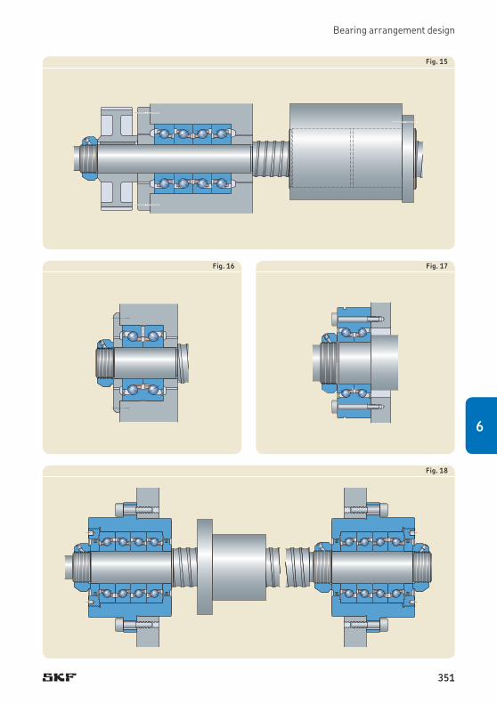
Bearing arrangement design
Fig. 15
Fig. 18
Fig. 16 Fig. 17
351
6

Angular contact thrust ball bearings for screw drives
Markings on bearingsEach super-precision angular contact thrust ball bearing and cartridge unit has various markings on the outside surfaces († fig. 19):
1 SKF trademark2 Complete designation of the bearing/unit3 Country of manufacture4 Date of manufacture, coded5 “MATCHABLE” label (single direction bear-
ings only)
“V-shaped” markingA “V-shaped” marking on the outside surface of the outer rings of universally matchable sin-gle direction bearings indicates how the bear-ing set should be mounted in relation to the axial load. The “V-shaped” marking points toward the side face of the inner ring that can support axial load. For sets of bearings, the large inner ring side face of the outer bearing should support axial load and should be mounted so that the “V-shaped” marking points in the direction opposite the axial load († fig. 20). In applications where there are axial loads in both directions supported by face-to-face or back-to-back arrangements, the inner ring side face of the outer bearing, to which the majority of the “V-shaped” markings point to, should support the heavier of the axial loads.
Fa
Fig. 20
F
BSA
20
8/QBCA Austria 282K
S
KF
SKF
2
MATCHA LB E
9H82 ZR1
23
54
AUSTRIABSA 206 C GA
SKF2 2K8
13 4
2 GERMANY BEAS 012042-2RS
Single direction bearing Double direction bearing Cartridge unit
1 4
2 3
-
Fig. 19
352

Bearing data
Bearing dataSingle direction bearings Double direction
bearingsCartridge units
Dimension standards
ISO 15, only for BSA 2 and BSA 3 series that are in accordance with 02 and 03 ISO dimension series respectively
BSD series bearings partly follow ISO dimension series
Not standardized Not standardized
Tolerances
For additional information († page 47)
P4 dimensional accuracyP2 running accuracyValues: ISO 492 († table 5, page 354)
The values apply to indi-vidual bearings. For matched bearing sets, the axial run-out is usually within 2,5 µm if the bearing seats are machined precisely and the bearings are mounted properly.
P4 running accuracy Values: ISO 492 († table 5354)Dimensional accuracyvalues: † table 5354
Values: † table 6, page 354
353
6

Angular contact thrust ball bearings for screw drives
Table 5
Tolerances of single and double direction bearings
Inner ring and bearing heightSingle direction bearings Double direction bearings
d Δds, Δdmp ΔTs Sia Δds, Δdmp ΔBs Siaover incl. high low high low max. high low high low max.
mm µm µm µm µm µm µm
10 18 0 –4 0 –80 1,5 0 –5 0 –250 218 25 0 –4 0 –120 2,5 0 –5 0 –250 225 30 0 –4 0 –120 2,5 0 –5 0 –250 2,5
30 50 0 –5 0 –120 2,5 0 –5 0 –250 2,550 60 0 –5 0 –120 2,5 0 –8 0 –250 2,560 80 0 –5 0 –120 2,5 0 –8 0 –250 3
Outer ringSingle direction bearings Double direction bearings
D ΔDs, ΔDmp Sea ΔDs, ΔDmp ΔCs Seaover incl. high low max. high low high low max.
mm µm µm µm µm µm
30 50 0 –5 2,5 0 –10 0 –250 850 80 0 –6 4 0 –10 0 –250 1080 110 0 –6 5 0 –10 0 –250 11
110 120 0 –6 5 0 –15 0 –250 11120 150 0 –7 5 0 –15 0 –250 13
Tolerance symbols and definitions † table 4, page 48
Table 6
Tolerances of cartridge units
d Δds, Δdmp ΔD2 ΔTs Sia1)
over incl. high low high low high low max.
mm µm µm mm µm
18 30 0 –4 0 –13 0 –1,5 2,530 50 0 –5 0 –15 0 –1,5 2,550 60 0 –5 0 –18 0 –1,5 2,5
Tolerance symbols and definitions † table 4, page 481) Axial run-out of a single bearing. The tolerance for the rectangularity of the flange to the housing seat diameter D2 is 5 to 10 µm
depending on the size.
354

Preload
PreloadSingle direction bearingsAn individual single direction angular contact thrust ball bearing cannot be preloaded until a second bearing provides location in the oppos-ite direction.
SKF single direction bearings are universally matchable as standard and are manufactured pre-set to two different preload classes:
• class A, light preload• class B, moderate preload
The amount of preload depends on various factors and applies to bearing sets in back-to-back or face-to-face arrangements. Preload values are not standardized and are listed in table 7 († page 356). The values do not cover influences from fits or operating conditions.
Bearing sets with a non-standard preload can be supplied on request. These bearing sets are identified by the designation suffix G fol-lowed by a number. The number is the mean preload value of the set expressed in daN.
Bearing sets consisting of three or four bearings have a heavier preload than sets with two bearings. The preload for these bearing sets is obtained by multiplying the values listed in table 7 by a factor listed in table 8 († page 356).
Double direction bearingsPreload values for double direction angular contact thrust ball bearings are not standard-ized and are listed in table 9 († page 357). The values do not cover influences from fits or operating conditions.
Bearings with a different preload can be supplied on request.
Cartridge unitsCartridge units contain single direction bear-ings with class A or B preload values as stand-ard († table 7, page 356). Units containing bearings with a non-standard preload can be supplied on request. Bearings sets with a non-standard preload are identified by the designa-tion suffix G followed by a number. The num-ber is the mean preload value of the set expressed in daN.
355
6

Angular contact thrust ball bearings for screw drives
Table 7
Axial preload, axial stiffness, frictional moment and maximum axial load of single direction bearings
Designation Axial preload Axial stiffness Frictional moment Maximum axial loadfor preload class for preload class for preload class
A B A B A B
– N N/µm Nm kN
BSA 201 650 1 300 400 510 0,016 0,028 6,25BSA 202 770 1 540 460 580 0,022 0,038 8,5BSA 203 1 040 2 080 550 700 0,04 0,072 10,3
BSA 204 1 480 2 960 680 860 0,05 0,091 14,5BSA 205 1 580 3 160 725 925 0,069 0,12 18BSA 206 2 150 4 300 870 1 110 0,12 0,21 22,6
BSA 207 2 950 5 900 1 080 1 370 0,18 0,32 29,6BSA 208 3 400 6 800 1 130 1 440 0,212 0,46 37,9BSA 209 3 750 7 500 1 290 1 640 0,23 0,52 40,2
BSA 210 4 100 8 200 1 410 1 800 0,31 0,68 42,5BSA 212 6 050 12 100 1 640 2 080 0,54 1,05 65BSA 215 6 850 13 700 1 870 2 380 0,65 1,4 76
BSA 305 2 150 4 300 870 1 110 0,12 0,2 22,6BSA 306 3 000 6 000 1 010 1 280 0,175 0,32 46BSA 307 4 100 8 200 1 120 1 430 0,26 0,46 65BSA 308 5 100 10 200 1 340 1 710 0,35 0,62 78,2
BSD 2047 1 480 2 960 680 860 0,05 0,091 14,5BSD 2562 2 150 4 300 870 1 110 0,115 0,21 22,6BSD 3062 2 150 4 300 870 1 110 0,125 0,215 22,6
BSD 3572 2 950 5 900 1 080 1 370 0,18 0,32 29,6BSD 4072 2 950 5 900 1 080 1 370 0,18 0,32 29,6BSD 4090 5 100 10 200 1 340 1 710 0,35 0,61 78,2
BSD 4575 2 900 5 800 1 180 1 500 0,25 0,41 40,2BSD 45100 5 850 11 700 1 470 1 870 0,5 0,97 107,4BSD 50100 6 200 12 400 1 550 1 970 0,52 0,97 107,4
BSD 55100 6 200 12 400 1 550 1 970 0,52 0,97 107,4BSD 55120 7 300 14 600 1 800 2 300 0,72 1,26 130BSD 60120 7 300 14 600 1 800 2 300 0,72 1,26 130
Table 8
Factors for calculating the preload and frictional moment of a bearing set
Number of bearings
Arrangement
Designation suffix
Factor
3 Back-to-back and tandem TBT 1,35Face-to-face and tandem TFT 1,35
4 Back-to-back and tandem QBT 1,55Face-to-face and tandem QFT 1,55Tandem back-to-back QBC 2Tandem face-to-face QFC 2
356

Preload
Table 9
Axial preload, stiffness, and frictional moment of double direction bearings
Designation Axial preload Stiffness Frictional moment1)
for preload class Axial Moment for preload class
– N N/µm Nm/rad Nm
BEAS 008032 300 250 20 0,08BEAS 012042 600 350 80 0,16BEAS 015045 650 400 65 0,2
BEAS 017047 720 420 80 0,24BEAS 020052 1 650 650 150 0,3BEAS 025057 1 920 770 200 0,4
BEAS 030062 2 170 870 300 0,54
BEAM 012055 600 350 80 0,16BEAM 017062 720 420 80 0,24BEAM 020068 1 650 650 150 0,3
BEAM 025075 1 920 770 200 0,4BEAM 030080 2 170 870 300 0,5BEAM 030100 3 900 950 470 0,8
BEAM 035090 2 250 900 400 0,6BEAM 040100 2 550 1 000 570 0,7BEAM 040115 4 750 1 150 720 1,3
BEAM 050115 3 100 1 250 1 000 0,69BEAM 050140 5 720 1 350 1 500 2,6BEAM 060145 4 700 1 400 1 750 2
1) The guideline values apply to bearings with contact seals (designation suffix 2RS). For bearings with non-contact seals (designation suffix 2RZ), the frictional moment is 50% of the values listed above.
357
6

Angular contact thrust ball bearings for screw drives
Axial stiffnessSingle direction bearingsThe axial stiffness values for single direction bearings are listed in table 7 († page 356). They apply to unmounted bearing sets with two bearings arranged back-to-back or face-to-face.
Bearing sets consisting of three or four bearings provide a higher degree of axial stiff-ness than sets with two bearings. The axial stiffness for these bearing sets is obtained by multiplying the values listed in table 7 by a factor listed in table 10. The lower value factor applies to bearings under light axial load (P ≤ 0,05 C) and the larger value to bearings under heavy axial load (P > 0,1 C). To deter-mine the equivalent dynamic bearing load P, refer to page 361.
Bearing sets with a heavier preload provide an even higher degree of stiffness. However, this should be avoided as heavier preload sub-stantially increases friction and heat generated by the bearing. In cases where an extremely high degree of stiffness is required, the fric-tional behaviour as a function of increasing preload can be estimated using the simulation tool SKF Spindle Simulator. For additional information, contact the SKF application en gin-eer ing service.
Double direction bearingsValues for axial and moment stiffness for double direction angular contact thrust ball bearings are listed in table 9 († page 357)
Table 10
Factors for calculating the axial stiffness of a bearing set
Number of bearings
Arrangement
Designation suffix
Factor
3 Back-to-back and tandem TBT 1,45 to 1,65Face-to-face and tandem TFT 1,45 to 1,65
4 Back-to-back and tandem QBT 1,8 to 2,25Face-to-face and tandem QFT 1,8 to 2,25Tandem back-to-back QBC 2Tandem face-to-face QFC 2
and apply to the preload set at the factory. The values do not cover influences from fits or operating conditions.
Cartridge unitsFor cartridge units, axial stiffness is listed in table 11. The values correspond to those for the included single direction bearings, multi-plied by the factors provided in table 10.
358

Axial stiffness
Table 11
Axial stiffness and frictional moment of cartridge units
Designation Axial stiffness Frictional momentfor preload class for preload classA B A B
– N/µm Nm
FBSA 204/DB 680 860 0,05 0,091FBSA 204/DF 680 860 0,05 0,091FBSA 204/QBC 1360 1720 0,1 0,182FBSA 204/QFC 1360 1720 0,1 0,182
FBSA 205/DB 725 925 0,069 0,12FBSA 205/DF 725 925 0,069 0,12FBSA 205/QBC 1450 1850 0,138 0,24FBSA 205/QFC 1450 1850 0,138 0,24
FBSA 206/DB 870 1110 0,12 0,21FBSA 206/DF 870 1110 0,12 0,21FBSA 206/QBC 1740 2220 0,24 0,42
FBSA 206/QFC 1740 2220 0,24 0,42FBSA 206 A/QBC 1740 2220 0,24 0,42FBSA 206 A/QFC 1740 2220 0,24 0,42
FBSA 207/DB 1080 1370 0,18 0,32FBSA 207/DF 1080 1370 0,18 0,32FBSA 207/QBC 2160 2740 0,36 0,64FBSA 207/QFC 2160 2740 0,36 0,64
FBSA 208/DB 1130 1440 0,212 0,46FBSA 208/DF 1130 1440 0,212 0,46FBSA 208/QBC 2260 2880 0,424 0,92
FBSA 208/QFC 2260 2880 0,424 0,92FBSA 208 A/QBC 2260 2880 0,424 0,92FBSA 208 A/QFC 2260 2880 0,424 0,92
FBSA 209/DB 1290 1640 0,23 0,52FBSA 209/DF 1290 1640 0,23 0,52FBSA 209/QBC 2580 3280 0,46 1,04FBSA 209/QFC 2580 3280 0,46 1,04
FBSA 210/DB 1410 1800 0,31 0,68FBSA 210/DF 1410 1800 0,31 0,68FBSA 210/QBC 2820 3600 0,62 1,36
FBSA 210/QFC 2820 3600 0,62 1,36FBSA 210 A/QBC 2820 3600 0,62 1,36FBSA 210 A/QFC 2820 3600 0,62 1,36
FBSA 212 A/QBC 3280 4160 1,08 2,1FBSA 212 A/QFC 3280 4160 1,08 2,1
359
6

Angular contact thrust ball bearings for screw drives
Frictional momentAll SKF angular contact thrust ball bearings for screw drives are designed for low friction operation. The frictional moment depends on the preload, operational speed, seals and quantity of lubricant in the bearing set. The starting torque is typically double the frictional moment.
Single direction bearingsGuideline values for the frictional moment of single direction bearings are listed in table 7 († page 356) and apply to unmounted bear-ing sets with two bearings arranged back-to-back or face-to-face that will operate at slow speeds.
Bearing sets consisting of three or four bearings have a higher frictional moment than sets with two bearings. The frictional moment for these bearing sets is obtained by multiply-ing the values in table 7 by a factor provided in table 8 († page 356).
Double direction bearingsGuideline values for the frictional moment of double direction bearings are listed in table 9 († page 357) and apply to unmounted bear-ings that will operate at slow speeds.
Cartridge unitsGuideline values for the frictional moment of cartridge units are listed in table 11 († page 359) and apply to unmounted bear-ings that will operate at slow speeds.
Lifting forceThe external axial load on a preloaded bearing set or double direction bearing causing one ball set to become completely unloaded is called the lifting force († Influence of an external load on preloaded bearing sets, page 91). The lifting force for sets of single direction bearings arranged back-to-back or face-to-face and double direction bearings can be estimated using
Ka1 = 2,83 F0
whereKa1 = lifting forceF0 = preload on bearings before external axial
load is applied († table 7, page 356 and table 9, page 357)
For additional information, contact the SKF application engineering service.
360

Equivalent bearing loads
Load carrying capacity of bearing setsThe dynamic load rating C and the static load rating C0, as well as the fatigue load limit Pu listed in the product tables for single direction bearings apply to axial loads for individual bearings. For bearing sets, the relevant values can be obtained by applying the factors listed in table 12 to the ratings listed for single bearings.
Equivalent bearing loadsEquivalent dynamic bearing loadIf individual single direction bearings, bearing sets, or double direction bearings have to accommodate both axial and radial loads, the equivalent dynamic bearing load for each direction of axial load can be determined as follows:
Fa/Fr ≤ 2,35 † P = X Fr + Y FaFa/Fr > 2,35 † P = 0,97 Fr + Fa
For bearings that accommodate axial loads only:
P = Fa
Table 12
Load ratings, fatigue load limit, and calculation factors for bearing sets with single direction bearings
Number of bearings
Arrangement Designa-tion suffix
Graphic repre-sentation
Load direc-tion
Load rating of bearing set
Fatigue load limit of bearing set
Calculation factors
dynamic static X Y
2 Back-to-back DB <> d C C0 Pu 2,04 0,54Face-to-face DF >< d C C0 Pu 2,04 0,54Tandem DT << d 1,63 C 2 C0 2 Pu – –
3 Back-to-back and tandem TBT <>> d C C0 Pu 1,54 0,75<>> a 1,63 C 2 C0 2 Pu 2,5 0,33
Face-to-face and tandem TFT ><< a C C0 Pu 1,54 0,75><< d 1,63 C 2 C0 2 Pu 2,5 0,33
Tandem TT <<< d 2,16 C 3 C0 3 Pu – –
4 Back-to-back and tandem QBT <<<> a C C0 Pu 1,26 0,87<<<> d 2,16 C 3 C0 3 Pu 2,71 0,25
Face-to-face and tandem QFT ><<< a C C0 Pu 1,26 0,87><<< d 2,16 C 3 C0 3 Pu 2,71 0,25
Tandem back-to-back QBC <<>> d 1,63 C 2 C0 2 Pu 2,04 0,54Tandem face-to-face QFC >><< d 1,63 C 2 C0 2 Pu 2,04 0,54Tandem QT <<<< d 2,64 C 4 C0 4 Pu – –
361
6

Angular contact thrust ball bearings for screw drives
whereP = equivalent dynamic load [kN]Fr = radial load [kN]Fa = axial load [kN]X = radial load factor
– for single direction bearings: † table 12, page 361
– for double direction bearings: 1,9Y = axial load factor
– for single direction bearings: † table 12
– for double direction bearings: 0,55
Preload is considered to be an axial load. For bearing sets in any arrangement, the equiva-lent dynamic bearing load must be calculated separately for each load direction.
Equivalent static bearing loadIf individual single direction bearings, bearing sets, or double direction bearings have to accommodate both axial and radial loads, the equivalent static bearing load for each direc-tion of axial load can be determined as follows:
P0 = Fa + 4,35 Fr
whereP0 = equivalent static load [kN]Fr = radial load [kN]Fa = axial load [kN]
Preload is considered to be an axial load. For bearing sets, in any arrangement, the equiva-lent static bearing load must be calculated separately for each load direction.
The equation for equivalent static bearing load applies to individual bearings and for bearings in a tandem arrangement if the load ratio Fa/Fr is not lower than 4. When Fa/Fr is between 4 and 2,5 the equation still provides useable approximation values.
Axial load carrying capacityWith increasing axial load, the contact condi-tions in the bearing change. The contact angle and especially the size of the contact ellipses increase, and there may be increased stress at the ring shoulder/raceway transitions. This stress is kept to a minimum for SKF super-precision bearings by appropriate measures, such as rounded and ground transition zones. Even so, the guideline values for the maximum axial load († table 7, page 356) should not be exceeded.
MountingMounting instructions are either printed on the inside of the bearing box or included as a leaf-let. For general information about mounting and dismounting super-precision bearings, refer to Mounting and dismounting († page 123).
362

Bearing data
Attainable speedsThe attainable speeds listed in the product tables are guideline values and are valid under certain conditions. For additional information, refer to Attainable speeds on page 44.
Single direction bearingsThe values listed for oil lubrication apply to the oil-air lubrication method and should be reduced if other oil lubrication methods are used.
The values listed for grease lubrication are maximum values that can be attained with sealed bearings or open bearings with an appropriate fill of a suitable, high-quality, soft consistency grease. For additional information, contact the SKF application engineering service.
If bearing sets with two or more bearings are mounted immediately adjacent to each other, the attainable speeds listed in the prod-uct tables need to be reduced. Values for the maximum rotational speeds in these cases can be obtained by multiplying the guideline value listed in the product tables by a reduction fac-tor († table 13) dependent on the preload and number of bearings in the arrangement.
Double direction bearingsThe attainable speeds listed in the product tables for double direction bearings depend on the type of seal and are limited as follows:
• for bearings with contact seals (designation suffix 2RS) by the permissible sliding speed at the seal lip
• for bearings with non-contact seals (desig-nation suffix 2RZ) by the speeds permitted for grease lubrication
Cartridge unitsThe attainable speeds listed in the product tables for cartridge units apply to mounted, grease lubricated units.
Table 13
Speed reduction factors for bearing sets
Number of bearings
Speed reduction factorfor preload class
A B
2 0,8 0,43 0,65 0,34 0,5 0,25
363
6

Angular contact thrust ball bearings for screw drives
Designation system
Bearing series
BSA 2 Single direction bearing in the 02 ISO dimension seriesBSA 3 Single direction bearing in the 03 ISO dimension seriesBSD Single direction bearingBEAM Double direction bearing for bolt mountingBEAS Double direction bearingFBSA 2 Cartridge unit with a flanged housing
Bearing size
For single direction bearings in accordance with an ISO dimension series01 12 mm bore diameter02 15 mm bore diameter03 17 mm bore diameter04 (x5) 20 mm bore diameterto15 (x5) 75 mm bore diameter
For single direction bearings, not standardized2047 20 mm bore diameter and 47 mm outside diameterto60120 60 mm bore diameter and 120 mm outside diameter
For double direction bearings008032 8 mm bore diameter and 32 outside diameterto060145 60 mm bore diameter and 145 mm outside diameter
Design features
C Improved internal design (single direction bearings only)A Different flange position (cartridge units only)
Single direction bearing – execution and preload
GA Universally matchable, light preloadGB Universally matchable, moderate preloadG… Universally matchable, special preload, expressed in daN e.g. G240
Sealing solutions
-2RS Contact seal on both sides, NBR-2RZ Non-contact seal on both sides, NBR
Examples: Single direction bearing – BSA 205 CGB/GMM BSA 2 05 C GB / GMM
Matched set of single direction bearings – BSA 208 C/TFTA BSA 2 08 C / TFT A
Double direction bearing – BEAM 030080-2RS/PE BEAM 030080 -2RS PE
Cartridge unit – FBSA 206 A/QBCA FSBA 2 06 A QBC A
364

Designation system
Bearing set – preload
A Light preloadB Moderate preloadG… Special preload, expressed in daN e.g. G240
Bearing arrangement
DB Set of two bearings arranged back-to-back <>DF Set of two bearings arranged face-to-face ><DT Set of two bearings arranged in tandem <<TBT Set of three bearings arranged back-to-back and tandem <>>TFT Set of three bearings arranged face-to-face and tandem ><<TT Set of three bearings arranged in tandem <<<QBC Set of four bearings arranged tandem back-to-back <<>>QFC Set of four bearings arranged tandem face-to-face >><<QBT Set of four bearings arranged back-to-back and tandem <>>>QFT Set of four bearings arranged face-to-face and tandem ><<<QT Set of four bearings arranged in tandem <<<<
Tolerance class
– Dimensional accuracy to ISO tolerance class 4, running accuracy to ISO tolerance class 2
PE Enlarged diameter tolerance and axial run-out to P5 tolerance class for radial bearing (BEAM/BEAS series only)
Grease fill
GMM Open single direction bearing filled with standard grease
Examples: Single direction bearing – BSA 205 CGB/GMM BSA 2 05 C GB / GMM
Matched set of single direction bearings – BSA 208 C/TFTA BSA 2 08 C / TFT A
Double direction bearing – BEAM 030080-2RS/PE BEAM 030080 -2RS PE
Cartridge unit – FBSA 206 A/QBCA FSBA 2 06 A QBC A
365
6

12 32 10 11,8 21,2 0,8 14 000 17 000 0,043 BSA 201 C 12 17,8 22 22,1 26,7 0,6 26 17 29 0,6 0,4
15 35 11 12,7 25,5 0,95 12 000 15 000 0,054 BSA 202 C 15 20,8 25 25,1 29,6 0,6 29 20 32 0,6 0,5
17 40 12 16,6 34,5 1,27 11 000 15 000 0,078 BSA 203 C 17 24,1 29 29,1 34,4 0,6 33 23 37 0,6 0,5
20 47 14 22 49 1,8 9 500 12 000 0,12 BSA 204 C 20 29,4 34,5 29,1 40,7 1 40 24 42 1 1,247 15 22 49 1,8 9 500 12 000 0,13 BSD 2047 C 29,4 34,5 34,6 40,7 1 40 27 42,5 1 1,4
25 52 15 22,4 52 1,93 9 000 11 000 0,15 BSA 205 C 25 33,4 38,5 38,6 44,7 1 44 32 47,5 1 1,562 15 28,5 71 2,65 8 000 9 500 0,24 BSD 2562 C 39,9 46 46,1 53 1 51 34 57 1 262 17 28,5 71 2,65 8 000 9 500 0,27 BSA 305 C 39,9 46 46,1 53 1 52 34 57 1 2,4
30 62 15 28,5 71 2,65 8 000 9 500 0,22 BSD 3062 C 30 39,9 46 46,1 53 1 51 38 57 1 262 16 28,5 71 2,65 8 000 9 500 0,23 BSA 206 C 39,9 46 46,1 53 1 51 37 57 1 2,272 19 41,5 104 3,9 7 000 9 500 0,41 BSA 306 C 43,9 51 51,1 59,5 1 57 40 65,5 1 3,5
35 72 15 36,5 98 3,65 7 500 9 000 0,3 BSD 3572 C 35 48,6 55 55,1 62,7 1,1 59 44 64,8 1 2,572 17 36,5 98 3,65 7 500 9 000 0,33 BSA 207 C 48,6 55 55,1 62,7 1,1 60 44 66 1 380 21 57 146 5,4 6 700 9 500 0,56 BSA 307 C 50,1 58,5 58,6 68,6 1 66 47 72,5 1 4,2
40 72 15 36,5 98 3,65 7 500 9 000 0,26 BSD 4072 C 40 48,6 55 55,1 62,7 1,1 59 47,5 65 1 2,580 18 42,5 112 4,15 6 300 7 500 0,43 BSA 208 C 50,3 58 58,1 66,5 1,1 64 48 74 1 3,790 20 64 170 6,3 6 000 7 000 0,68 BSD 4090 C 57,5 66,5 66,6 77,3 1,5 73 53 81 1,5 5,290 23 67 180 6,7 5 300 7 000 0,77 BSA 308 C 57,5 66,5 66,6 77,3 1,5 74 53 81 1,5 6,4
45 75 15 32,5 98 3,65 7 500 9 000 0,26 BSD 4575 C 45 54,3 60 60,1 66,9 1,1 64 53 69 1 2,785 18 45 134 4,9 6 300 7 500 0,51 BSA 209 C 59,4 67 67,1 75,5 1,1 73 53 79,5 1 4,5100 20 65,5 183 6,7 5 600 6 700 0,77 BSD 45100 C 61,7 71,5 71,6 82,3 1,5 77 59 90 1,5 5,9
50 90 20 46,5 146 5,4 6 000 7 000 0,56 BSA 210 C 50 64,4 72 72,1 80,5 1,1 78 59 84 1 5,2100 20 67 193 7,2 5 600 6 700 0,71 BSD 50100 C 66,9 77 77,1 87,8 1,5 82 65 90,5 1,5 6,5
55 100 20 67 193 7,2 5 600 6 700 0,66 BSD 55100 C 55 66,9 77 77,1 87,8 1,5 82 67 91 1,5 6,5120 20 69,5 228 8,5 5 000 6 000 1,15 BSD 55120 C 80,9 91 91,1 101,8 1,5 96 69 110 1,5 7,5
60 110 22 69,5 216 8 5 000 6 000 0,95 BSA 212 C 60 76,9 87 87,1 97,8 1,1 93 71 102 1,5 8,5120 20 69,5 228 8,5 5 000 6 000 1,05 BSD 60120 C 80,9 91 91,1 101,8 1,5 96 73 111 1,5 7,5
75 130 25 72 245 9,15 4 300 5 000 1,45 BSA 215 C 75 91,2 100 100,1 110,8 1,5 107 85 122 1,5 11
D2D1 d1
r2 r2
r1 r1
r1
r2r2r1
D
H
d2d
a
Principal dimensions Basic load ratings Fatigue
load limitAttainable speeds Mass Designation Dimensions Abutment and fillet dimensions Reference
grease quantity1)
Grease lubrica-tion
Oil-air lubricationdynamic static
d D H C C0 Pu d d1 d2 D1 D2 r1,2 a da Da ra Gref~ ~ ~ ~ min. min. max. max.
mm kN kN r/min kg – mm mm cm3
6.1 Single direction angular contact thrust ball bearingsd 12 – 75 mm
366

12 32 10 11,8 21,2 0,8 14 000 17 000 0,043 BSA 201 C 12 17,8 22 22,1 26,7 0,6 26 17 29 0,6 0,4
15 35 11 12,7 25,5 0,95 12 000 15 000 0,054 BSA 202 C 15 20,8 25 25,1 29,6 0,6 29 20 32 0,6 0,5
17 40 12 16,6 34,5 1,27 11 000 15 000 0,078 BSA 203 C 17 24,1 29 29,1 34,4 0,6 33 23 37 0,6 0,5
20 47 14 22 49 1,8 9 500 12 000 0,12 BSA 204 C 20 29,4 34,5 29,1 40,7 1 40 24 42 1 1,247 15 22 49 1,8 9 500 12 000 0,13 BSD 2047 C 29,4 34,5 34,6 40,7 1 40 27 42,5 1 1,4
25 52 15 22,4 52 1,93 9 000 11 000 0,15 BSA 205 C 25 33,4 38,5 38,6 44,7 1 44 32 47,5 1 1,562 15 28,5 71 2,65 8 000 9 500 0,24 BSD 2562 C 39,9 46 46,1 53 1 51 34 57 1 262 17 28,5 71 2,65 8 000 9 500 0,27 BSA 305 C 39,9 46 46,1 53 1 52 34 57 1 2,4
30 62 15 28,5 71 2,65 8 000 9 500 0,22 BSD 3062 C 30 39,9 46 46,1 53 1 51 38 57 1 262 16 28,5 71 2,65 8 000 9 500 0,23 BSA 206 C 39,9 46 46,1 53 1 51 37 57 1 2,272 19 41,5 104 3,9 7 000 9 500 0,41 BSA 306 C 43,9 51 51,1 59,5 1 57 40 65,5 1 3,5
35 72 15 36,5 98 3,65 7 500 9 000 0,3 BSD 3572 C 35 48,6 55 55,1 62,7 1,1 59 44 64,8 1 2,572 17 36,5 98 3,65 7 500 9 000 0,33 BSA 207 C 48,6 55 55,1 62,7 1,1 60 44 66 1 380 21 57 146 5,4 6 700 9 500 0,56 BSA 307 C 50,1 58,5 58,6 68,6 1 66 47 72,5 1 4,2
40 72 15 36,5 98 3,65 7 500 9 000 0,26 BSD 4072 C 40 48,6 55 55,1 62,7 1,1 59 47,5 65 1 2,580 18 42,5 112 4,15 6 300 7 500 0,43 BSA 208 C 50,3 58 58,1 66,5 1,1 64 48 74 1 3,790 20 64 170 6,3 6 000 7 000 0,68 BSD 4090 C 57,5 66,5 66,6 77,3 1,5 73 53 81 1,5 5,290 23 67 180 6,7 5 300 7 000 0,77 BSA 308 C 57,5 66,5 66,6 77,3 1,5 74 53 81 1,5 6,4
45 75 15 32,5 98 3,65 7 500 9 000 0,26 BSD 4575 C 45 54,3 60 60,1 66,9 1,1 64 53 69 1 2,785 18 45 134 4,9 6 300 7 500 0,51 BSA 209 C 59,4 67 67,1 75,5 1,1 73 53 79,5 1 4,5100 20 65,5 183 6,7 5 600 6 700 0,77 BSD 45100 C 61,7 71,5 71,6 82,3 1,5 77 59 90 1,5 5,9
50 90 20 46,5 146 5,4 6 000 7 000 0,56 BSA 210 C 50 64,4 72 72,1 80,5 1,1 78 59 84 1 5,2100 20 67 193 7,2 5 600 6 700 0,71 BSD 50100 C 66,9 77 77,1 87,8 1,5 82 65 90,5 1,5 6,5
55 100 20 67 193 7,2 5 600 6 700 0,66 BSD 55100 C 55 66,9 77 77,1 87,8 1,5 82 67 91 1,5 6,5120 20 69,5 228 8,5 5 000 6 000 1,15 BSD 55120 C 80,9 91 91,1 101,8 1,5 96 69 110 1,5 7,5
60 110 22 69,5 216 8 5 000 6 000 0,95 BSA 212 C 60 76,9 87 87,1 97,8 1,1 93 71 102 1,5 8,5120 20 69,5 228 8,5 5 000 6 000 1,05 BSD 60120 C 80,9 91 91,1 101,8 1,5 96 73 111 1,5 7,5
75 130 25 72 245 9,15 4 300 5 000 1,45 BSA 215 C 75 91,2 100 100,1 110,8 1,5 107 85 122 1,5 11
Da da
ra
Da da
ra
Principal dimensions Basic load ratings Fatigue
load limitAttainable speeds Mass Designation Dimensions Abutment and fillet dimensions Reference
grease quantity1)
Grease lubrica-tion
Oil-air lubricationdynamic static
d D H C C0 Pu d d1 d2 D1 D2 r1,2 a da Da ra Gref~ ~ ~ ~ min. min. max. max.
mm kN kN r/min kg – mm mm cm3
1) For calculating the initial grease fill † page 101
367
6.1

8 32 20 12,5 16,3 0,6 5 300 0,09 BEAS 008032-2RS 8 19 26,5 0,3 0,6 43 12 26 0,3 0,632 20 12,5 16,3 0,6 8 800 0,09 BEAS 008032-2RZ 19 26,5 0,3 0,6 43 12 26 0,3 0,6
12 42 25 16,8 24,5 0,915 4 000 0,2 BEAS 012042-2RS 12 25 33,5 0,3 0,6 56 16 35 0,3 0,642 25 16,8 24,5 0,915 6 700 0,2 BEAS 012042-2RZ 25 33,5 0,3 0,6 56 16 35 0,3 0,6
15 45 25 18 28 1,04 3 900 0,21 BEAS 015045-2RS 15 28 36 0,3 0,6 61 20 35 0,3 0,645 25 18 28 1,04 6 500 0,21 BEAS 015045-2RZ 28 36 0,3 0,6 61 20 35 0,3 0,6
17 47 25 18 31 1,16 3 800 0,22 BEAS 017047-2RS 17 30 38 0,3 0,6 65 23 40 0,3 0,647 25 19 31 1,16 6 300 0,22 BEAS 017047-2RZ 30 38 0,3 0,6 65 23 40 0,3 0,6
20 52 28 26 46,5 1,73 3 400 0,31 BEAS 020052-2RS 20 34,5 44 0,3 0,6 74 26 45 0,3 0,652 28 26 46,5 1,73 6 000 0,31 BEAS 020052-2RZ 34,5 44 0,3 0,6 74 26 45 0,3 0,652 28 26 46,5 1,73 6 000 0,31 BEAS 020052-2RZ/PE 34,5 44 0,3 0,6 74 26 45 0,3 0,6
25 57 28 27,6 55 2,04 3 400 0,34 BEAS 025057-2RS 25 40,5 49 0,3 0,6 84 32 50 0,3 0,657 28 27,6 55 2,04 5 600 0,34 BEAS 025057-2RZ 40,5 49 0,3 0,6 84 32 50 0,3 0,6
30 62 28 29 64 2,36 3 200 0,39 BEAS 030062-2RS 30 45,5 54 0,3 0,6 93 40 54 0,3 0,662 28 29 64 2,36 5 300 0,39 BEAS 030062-2RZ 45,5 54 0,3 0,6 93 40 54 0,3 0,6
2RS 2RZ
r3
Hr4
r2
D1 d1dD
a
r1
Principal dimensions Basic load ratings Fatigue
load limitAttainable speed
Mass Designation Dimensions Abutment and fillet dimensionsdynamic static
d D H C C0 Pu d d1 D1 r1,2 r3,4 a da Da ra rb~ ~ min. min. min. max. max. max.
mm kN kN r/min kg – mm mm
6.2 Double direction angular contact thrust ball bearingsd 8 – 30 mm
368

8 32 20 12,5 16,3 0,6 5 300 0,09 BEAS 008032-2RS 8 19 26,5 0,3 0,6 43 12 26 0,3 0,632 20 12,5 16,3 0,6 8 800 0,09 BEAS 008032-2RZ 19 26,5 0,3 0,6 43 12 26 0,3 0,6
12 42 25 16,8 24,5 0,915 4 000 0,2 BEAS 012042-2RS 12 25 33,5 0,3 0,6 56 16 35 0,3 0,642 25 16,8 24,5 0,915 6 700 0,2 BEAS 012042-2RZ 25 33,5 0,3 0,6 56 16 35 0,3 0,6
15 45 25 18 28 1,04 3 900 0,21 BEAS 015045-2RS 15 28 36 0,3 0,6 61 20 35 0,3 0,645 25 18 28 1,04 6 500 0,21 BEAS 015045-2RZ 28 36 0,3 0,6 61 20 35 0,3 0,6
17 47 25 18 31 1,16 3 800 0,22 BEAS 017047-2RS 17 30 38 0,3 0,6 65 23 40 0,3 0,647 25 19 31 1,16 6 300 0,22 BEAS 017047-2RZ 30 38 0,3 0,6 65 23 40 0,3 0,6
20 52 28 26 46,5 1,73 3 400 0,31 BEAS 020052-2RS 20 34,5 44 0,3 0,6 74 26 45 0,3 0,652 28 26 46,5 1,73 6 000 0,31 BEAS 020052-2RZ 34,5 44 0,3 0,6 74 26 45 0,3 0,652 28 26 46,5 1,73 6 000 0,31 BEAS 020052-2RZ/PE 34,5 44 0,3 0,6 74 26 45 0,3 0,6
25 57 28 27,6 55 2,04 3 400 0,34 BEAS 025057-2RS 25 40,5 49 0,3 0,6 84 32 50 0,3 0,657 28 27,6 55 2,04 5 600 0,34 BEAS 025057-2RZ 40,5 49 0,3 0,6 84 32 50 0,3 0,6
30 62 28 29 64 2,36 3 200 0,39 BEAS 030062-2RS 30 45,5 54 0,3 0,6 93 40 54 0,3 0,662 28 29 64 2,36 5 300 0,39 BEAS 030062-2RZ 45,5 54 0,3 0,6 93 40 54 0,3 0,6
Da da
ra
rb
Principal dimensions Basic load ratings Fatigue
load limitAttainable speed
Mass Designation Dimensions Abutment and fillet dimensionsdynamic static
d D H C C0 Pu d d1 D1 r1,2 r3,4 a da Da ra rb~ ~ min. min. min. max. max. max.
mm kN kN r/min kg – mm mm
369
6.2

12 55 25 16,8 24,5 0,915 4 000 0,37 BEAM 012055-2RS 12 25 33,5 17 0,3 0,6 56 16 33 0,6 M6 42 6,8 3x12055 25 16,8 24,5 0,915 6 700 0,37 BEAM 012055-2RZ 25 33,5 17 0,3 0,6 56 16 33 0,6 M6 42 6,8 3x120
17 62 25 19 31 1,16 3 800 0,45 BEAM 017062-2RS 17 30 38 17 0,3 0,6 65 23 38 0,6 M6 48 6,8 3x12062 25 19 31 1,16 3 800 0,45 BEAM 017062-2RZ 30 38 17 0,3 0,6 65 23 38 0,6 M6 48 6,8 3x12062 25 19 31 1,16 6 300 0,45 BEAM 017062-2RS/PE 30 38 17 0,3 0,6 65 23 38 0,6 M6 48 6,8 3x12062 25 19 31 1,16 6 300 0,45 BEAM 017062-2RZ/PE 30 38 17 0,3 0,6 65 23 38 0,6 M6 48 6,8 3x120
20 68 28 26 46,5 1,73 3 400 0,61 BEAM 020068-2RS 20 34,5 44 19 0,3 0,6 74 25 44 0,6 M6 53 6,8 4x9068 28 26 46,5 1,73 3 400 0,61 BEAM 020068-2RS/PE 34,5 44 19 0,3 0,6 74 25 44 0,6 M6 53 6,8 4x9068 28 26 46,5 1,73 6 000 0,61 BEAM 020068-2RZ 34,5 44 19 0,3 0,6 74 25 44 0,6 M6 53 6,8 4x9068 28 26 46,5 1,73 6 000 0,61 BEAM 020068-2RZ/PE 34,5 44 19 0,3 0,6 74 25 44 0,6 M6 53 6,8 4x90
25 75 28 27,6 55 2,04 3 400 0,72 BEAM 025075-2RS 25 40,5 49 19 0,3 0,6 84 32 49 0,6 M6 58 6,8 4x9075 28 27,6 55 2,04 3 400 0,72 BEAM 025075-2RS/PE 40,5 49 19 0,3 0,6 84 32 49 0,6 M6 58 6,8 4x9075 28 27,6 55 2,04 5 600 0,72 BEAM 025075-2RZ/PE 40,5 49 19 0,3 0,6 84 32 49 0,6 M6 58 6,8 4x9075 28 27,6 55 2,04 5 600 0,72 BEAM 025075-2RZ 40,5 49 19 0,3 0,6 84 32 49 0,6 M6 58 6,8 4x90
30 80 28 29,1 64 2,36 2 600 0,78 BEAM 030080-2RS 30 45,5 54 19 0,3 0,6 93 40 54 0,6 M6 63 6,8 6x6080 28 29,1 64 2,36 2 600 0,78 BEAM 030080-2RS/PE 45,5 54 19 0,3 0,6 93 40 54 0,6 M6 63 6,8 6x6080 28 29,1 64 2,36 4 500 0,78 BEAM 030080-2RZ 45,5 54 19 0,3 0,6 93 40 54 0,6 M6 63 6,8 6x60100 38 60 108 4 2 600 1,65 BEAM 030100-2RS 51 65 30 0,3 0,6 106 47 65 0,6 M8 80 8,8 8x45100 38 60 108 4 4 300 1,65 BEAM 030100-2RZ 51 65 30 0,3 0,6 106 47 65 0,6 M8 80 8,8 8x45
35 90 34 41 88 3,25 2 400 1,15 BEAM 035090-2RS 35 52 63 25 0,3 0,6 107 45 63 0,6 M8 75 8,8 4x9090 34 41 88 3,25 4 000 1,15 BEAM 035090-2RZ 52 63 25 0,3 0,6 107 45 63 0,6 M8 75 8,8 4x90
40 100 34 43,6 102 3,75 2 200 1,45 BEAM 040100-2RS 40 58 68 25 0,3 0,6 117 50 68 0,6 M8 80 8,8 4x90100 34 43,6 102 3,75 3 800 1,45 BEAM 040100-2RZ 58 68 25 0,3 0,6 117 50 68 0,6 M8 80 8,8 4x90115 46 71,5 150 5,5 1 800 2,2 BEAM 040115-2RS 65 80 36 0,6 0,6 134 56 80 0,6 M8 94 8,8 12x30115 46 71,5 150 5,5 3 000 2,2 BEAM 040115-2RZ 65 80 36 0,6 0,6 134 56 80 0,6 M8 94 8,8 12x30
50 115 34 46,8 127 4,65 2 000 1,85 BEAM 050115-2RS 50 72 82 25 0,3 0,6 141 63 82 0,6 M8 94 8,8 6x60115 34 46,8 127 4,65 3 600 1,85 BEAM 050115-2RZ 72 82 25 0,3 0,6 141 63 82 0,6 M8 94 8,8 6x60140 54 114 250 9,3 1 700 4,7 BEAM 050140-2RS 80 98 45 0,6 0,6 166 63 98 0,6 M10 113 11 12x30140 54 114 250 9,3 2 800 4,7 BEAM 050140-2RZ 80 98 45 0,6 0,6 166 63 98 0,6 M10 113 11 12x30
60 145 45 85 216 8 1 600 4,3 BEAM 060145-2RS 60 85 100 35 0,6 0,6 168 82 100 0,6 M8 120 8,8 8x45145 45 85 216 8 2 600 4,3 BEAM 060145-2RZ 85 100 35 0,6 0,6 168 82 100 0,6 M8 120 8,8 8x45
d = 60 mm PE
r3
r2
r1
d1
H1
a
D1D
N
3
J d
r4
M6
H
Principal dimensions Basic load ratings Fatigue
load limitAttainable speed
Mass Designation Dimensions Abutment and fillet dimensions
Holes for attachment bolts in accordance with DIN 912
dynamic static Size Dimensions Pitchd D H C C0 Pu d d1 D1 H1 r1,2 r3,4 a da Da ra J N nr. x a [°]
~ ~ ~ min. min. min. max. max.
mm kN kN r/min kg – mm mm – mm –
6.3 Double direction angular contact thrust ball bearings for bolt mountingd 12 – 60 mm
370

12 55 25 16,8 24,5 0,915 4 000 0,37 BEAM 012055-2RS 12 25 33,5 17 0,3 0,6 56 16 33 0,6 M6 42 6,8 3x12055 25 16,8 24,5 0,915 6 700 0,37 BEAM 012055-2RZ 25 33,5 17 0,3 0,6 56 16 33 0,6 M6 42 6,8 3x120
17 62 25 19 31 1,16 3 800 0,45 BEAM 017062-2RS 17 30 38 17 0,3 0,6 65 23 38 0,6 M6 48 6,8 3x12062 25 19 31 1,16 3 800 0,45 BEAM 017062-2RZ 30 38 17 0,3 0,6 65 23 38 0,6 M6 48 6,8 3x12062 25 19 31 1,16 6 300 0,45 BEAM 017062-2RS/PE 30 38 17 0,3 0,6 65 23 38 0,6 M6 48 6,8 3x12062 25 19 31 1,16 6 300 0,45 BEAM 017062-2RZ/PE 30 38 17 0,3 0,6 65 23 38 0,6 M6 48 6,8 3x120
20 68 28 26 46,5 1,73 3 400 0,61 BEAM 020068-2RS 20 34,5 44 19 0,3 0,6 74 25 44 0,6 M6 53 6,8 4x9068 28 26 46,5 1,73 3 400 0,61 BEAM 020068-2RS/PE 34,5 44 19 0,3 0,6 74 25 44 0,6 M6 53 6,8 4x9068 28 26 46,5 1,73 6 000 0,61 BEAM 020068-2RZ 34,5 44 19 0,3 0,6 74 25 44 0,6 M6 53 6,8 4x9068 28 26 46,5 1,73 6 000 0,61 BEAM 020068-2RZ/PE 34,5 44 19 0,3 0,6 74 25 44 0,6 M6 53 6,8 4x90
25 75 28 27,6 55 2,04 3 400 0,72 BEAM 025075-2RS 25 40,5 49 19 0,3 0,6 84 32 49 0,6 M6 58 6,8 4x9075 28 27,6 55 2,04 3 400 0,72 BEAM 025075-2RS/PE 40,5 49 19 0,3 0,6 84 32 49 0,6 M6 58 6,8 4x9075 28 27,6 55 2,04 5 600 0,72 BEAM 025075-2RZ/PE 40,5 49 19 0,3 0,6 84 32 49 0,6 M6 58 6,8 4x9075 28 27,6 55 2,04 5 600 0,72 BEAM 025075-2RZ 40,5 49 19 0,3 0,6 84 32 49 0,6 M6 58 6,8 4x90
30 80 28 29,1 64 2,36 2 600 0,78 BEAM 030080-2RS 30 45,5 54 19 0,3 0,6 93 40 54 0,6 M6 63 6,8 6x6080 28 29,1 64 2,36 2 600 0,78 BEAM 030080-2RS/PE 45,5 54 19 0,3 0,6 93 40 54 0,6 M6 63 6,8 6x6080 28 29,1 64 2,36 4 500 0,78 BEAM 030080-2RZ 45,5 54 19 0,3 0,6 93 40 54 0,6 M6 63 6,8 6x60100 38 60 108 4 2 600 1,65 BEAM 030100-2RS 51 65 30 0,3 0,6 106 47 65 0,6 M8 80 8,8 8x45100 38 60 108 4 4 300 1,65 BEAM 030100-2RZ 51 65 30 0,3 0,6 106 47 65 0,6 M8 80 8,8 8x45
35 90 34 41 88 3,25 2 400 1,15 BEAM 035090-2RS 35 52 63 25 0,3 0,6 107 45 63 0,6 M8 75 8,8 4x9090 34 41 88 3,25 4 000 1,15 BEAM 035090-2RZ 52 63 25 0,3 0,6 107 45 63 0,6 M8 75 8,8 4x90
40 100 34 43,6 102 3,75 2 200 1,45 BEAM 040100-2RS 40 58 68 25 0,3 0,6 117 50 68 0,6 M8 80 8,8 4x90100 34 43,6 102 3,75 3 800 1,45 BEAM 040100-2RZ 58 68 25 0,3 0,6 117 50 68 0,6 M8 80 8,8 4x90115 46 71,5 150 5,5 1 800 2,2 BEAM 040115-2RS 65 80 36 0,6 0,6 134 56 80 0,6 M8 94 8,8 12x30115 46 71,5 150 5,5 3 000 2,2 BEAM 040115-2RZ 65 80 36 0,6 0,6 134 56 80 0,6 M8 94 8,8 12x30
50 115 34 46,8 127 4,65 2 000 1,85 BEAM 050115-2RS 50 72 82 25 0,3 0,6 141 63 82 0,6 M8 94 8,8 6x60115 34 46,8 127 4,65 3 600 1,85 BEAM 050115-2RZ 72 82 25 0,3 0,6 141 63 82 0,6 M8 94 8,8 6x60140 54 114 250 9,3 1 700 4,7 BEAM 050140-2RS 80 98 45 0,6 0,6 166 63 98 0,6 M10 113 11 12x30140 54 114 250 9,3 2 800 4,7 BEAM 050140-2RZ 80 98 45 0,6 0,6 166 63 98 0,6 M10 113 11 12x30
60 145 45 85 216 8 1 600 4,3 BEAM 060145-2RS 60 85 100 35 0,6 0,6 168 82 100 0,6 M8 120 8,8 8x45145 45 85 216 8 2 600 4,3 BEAM 060145-2RZ 85 100 35 0,6 0,6 168 82 100 0,6 M8 120 8,8 8x45
ra
Da da
a
Principal dimensions Basic load ratings Fatigue
load limitAttainable speed
Mass Designation Dimensions Abutment and fillet dimensions
Holes for attachment bolts in accordance with DIN 912
dynamic static Size Dimensions Pitchd D H C C0 Pu d d1 D1 H1 r1,2 r3,4 a da Da ra J N nr. x a [°]
~ ~ ~ min. min. min. max. max.
mm kN kN r/min kg – mm mm – mm –
371
6.3

20 90 47 22 49 1,8 7 600 3 800 1,1 FBSA 204/DB 20 44,26 32 13 – 26 64 60 36 76 32 6,6 –90 47 22 49 1,8 7 600 3 800 1,1 FBSA 204/DF 43,24 32 13 – 26 64 60 36 76 32 6,6 –90 77 35,9 98 3,6 4 750 2 375 1,7 FBSA 204/QBC 74,26 32 13 – 26 64 60 36 76 32 6,6 –90 77 35,9 98 3,6 4 750 2 375 1,7 FBSA 204/QFC 72,74 32 13 – 26 64 60 36 76 32 6,6 –
25 120 52 22,4 52 1,93 7 200 3 600 2,3 FBSA 205/DB 25 50,26 32 15 – 34 88 80 36 102 44 9,2 –120 52 22,4 52 1,93 7 200 3 600 2,3 FBSA 205/DF 49,24 32 15 – 34 88 80 36 102 44 9,2 –120 82 36,5 104 3,86 4 500 2 250 3,5 FBSA 205/QBC 80,26 32 15 – 34 88 80 40 102 44 9,2 –120 82 36,5 104 3,86 4 500 2 250 3,5 FBSA 205/QFC 78,74 32 15 – 34 88 80 40 102 44 9,2 –
30 120 52 28,5 71 2,65 6 400 3 200 2,5 FBSA 206/DB 30 50,26 32 15 – 41 88 80 50 102 44 9,2 –120 52 28,5 71 2,65 6 400 3 200 2,5 FBSA 206/DF 49,24 32 15 – 41 88 80 50 102 44 9,2 –120 84 46,5 142 5,3 4 000 2 000 3,5 FBSA 206/QBC 82,26 32 15 – 41 88 80 50 102 44 9,2 –120 84 46,5 142 5,3 4 000 2 000 3,5 FBSA 206/QFC 80,74 32 15 – 41 88 80 50 102 44 9,2 –120 86 46,5 142 5,3 4 000 2 000 3,7 FBSA 206 A/QBC 86,26 3,5 15 35 41 88 88 50 102 45 9,2 M8x1,25120 86 46,5 142 5,3 4 000 2 000 3,7 FBSA 206 A/QFC 86,26 3,5 15 35 41 88 88 50 102 45 9,2 M8x1,25
35 130 52 36,5 98 3,65 5 600 2 800 3,2 FBSA 207/DB 35 50,26 32 15 – 46 98 90 60 113 49 9,2 –130 52 36,5 98 3,65 5 600 2 800 3,2 FBSA 207/DF 49,24 32 15 – 46 98 90 60 113 49 9,2 –130 86 59,5 196 7,3 3 500 1 750 4,6 FBSA 207/QBC 84,26 32 15 – 46 98 90 60 113 49 9,2 –130 86 59,5 196 7,3 3 500 1 750 4,6 FBSA 207/QFC 82,74 32 15 – 46 98 90 60 113 49 9,2 –
40 165 66 42,5 112 4,15 5 040 2 520 6,1 FBSA 208/DB 40 64,26 43,5 17 – 55 128 124 66 146 64 11,4 –165 66 42,5 112 4,15 5 040 2 520 6,1 FBSA 208/DF 63,24 43,5 17 – 55 128 124 66 146 64 11,4 –165 106 69,3 224 8,3 3 150 1 575 9,7 FBSA 208/QBC 104,26 43,5 17 – 55 128 124 66 146 64 11,4 –165 106 69,3 224 8,3 3 150 1 575 9,7 FBSA 208/QFC 102,74 43,5 17 – 55 128 124 66 146 64 11,4 –165 106 69,3 224 8,3 3 150 1 575 10 FBSA 208 A/QBC 106,26 4 24 35 55 128 128 66 146 65,5 11,4 M10x1,5165 106 69,3 224 8,3 3 150 1 575 10 FBSA 208 A/QFC 106,26 4 24 35 55 128 128 66 146 65,5 11,4 M10x1,5
45 165 66 45 134 4,9 5 040 2 520 5,9 FBSA 209/DB 45 64,26 43,5 17 – 66 128 124 76 146 64 11,4 –165 66 45 134 4,9 5 040 2 520 5,9 FBSA 209/DF 63,24 43,5 17 – 66 128 124 76 146 64 11,4 –165 106 73,4 268 9,8 3 150 1 575 9,4 FBSA 209/QBC 104,26 43,5 17 – 66 128 124 76 146 64 11,4 –165 106 73,4 268 9,8 3 150 1 575 9,4 FBSA 209/QFC 102,74 43,5 17 – 66 128 124 76 146 64 11,4 –
50 165 66 46,5 146 5,4 4 800 2 400 5,7 FBSA 210/DB 50 64,26 43,5 17 – 66 128 124 76 146 64 11,4 –165 66 46,5 146 5,4 4 800 2 400 5,7 FBSA 210/DF 63,24 43,5 17 – 66 128 124 76 146 64 11,4 –165 106 75,8 292 10,8 3 000 1 500 9,1 FBSA 210/QBC 104,26 43,5 17 – 66 128 124 76 146 64 11,4 –165 106 75,8 292 10,8 3 000 1 500 9,1 FBSA 210/QFC 102,74 43,5 17 – 66 128 124 76 146 64 11,4 –165 106 75,8 292 10,8 3 000 1 500 9,3 FBSA 210 A/QBC 106,26 4 24 35 66 128 128 76 146 65,5 11,4 M10x1,5165 106 75,8 292 10,8 3 000 1 500 9,3 FBSA 210 A/QFC 106,26 4 24 35 66 128 128 76 146 65,5 11,4 M10x1,5
60 185 114 113 432 16 2 500 1 250 12,5 FBSA 212 A/QBC 60 114,26 20,5 25 40 80 145 145 92 165 74,5 11,4 M10x1,5185 114 113 432 16 2 500 1 250 12,5 FBSA 212 A/QFC 114,26 20,5 25 40 80 145 145 92 165 74,5 11,4 M10x1,5
FBSA 2 .. /DB FBSA 2 .. /QBC
D2d1d
A3 A2
A1
A
D1JH D3D2d1d
A3 A2
A1
A
D1JH D3
6.4 Cartridge units with a flanged housingd 20 – 60 mm
Principal dimensions Basic load ratings Fatigue
load limitAttainable speeds Mass Designation Dimensions Holes for attachment boltsPreload class
dynamic staticd H A C C0 Pu A B d A1 A2 A3 C d1 D1 D2 D3 J J1 N G
mm kN kN r/min kg – mm mm
372

20 90 47 22 49 1,8 7 600 3 800 1,1 FBSA 204/DB 20 44,26 32 13 – 26 64 60 36 76 32 6,6 –90 47 22 49 1,8 7 600 3 800 1,1 FBSA 204/DF 43,24 32 13 – 26 64 60 36 76 32 6,6 –90 77 35,9 98 3,6 4 750 2 375 1,7 FBSA 204/QBC 74,26 32 13 – 26 64 60 36 76 32 6,6 –90 77 35,9 98 3,6 4 750 2 375 1,7 FBSA 204/QFC 72,74 32 13 – 26 64 60 36 76 32 6,6 –
25 120 52 22,4 52 1,93 7 200 3 600 2,3 FBSA 205/DB 25 50,26 32 15 – 34 88 80 36 102 44 9,2 –120 52 22,4 52 1,93 7 200 3 600 2,3 FBSA 205/DF 49,24 32 15 – 34 88 80 36 102 44 9,2 –120 82 36,5 104 3,86 4 500 2 250 3,5 FBSA 205/QBC 80,26 32 15 – 34 88 80 40 102 44 9,2 –120 82 36,5 104 3,86 4 500 2 250 3,5 FBSA 205/QFC 78,74 32 15 – 34 88 80 40 102 44 9,2 –
30 120 52 28,5 71 2,65 6 400 3 200 2,5 FBSA 206/DB 30 50,26 32 15 – 41 88 80 50 102 44 9,2 –120 52 28,5 71 2,65 6 400 3 200 2,5 FBSA 206/DF 49,24 32 15 – 41 88 80 50 102 44 9,2 –120 84 46,5 142 5,3 4 000 2 000 3,5 FBSA 206/QBC 82,26 32 15 – 41 88 80 50 102 44 9,2 –120 84 46,5 142 5,3 4 000 2 000 3,5 FBSA 206/QFC 80,74 32 15 – 41 88 80 50 102 44 9,2 –120 86 46,5 142 5,3 4 000 2 000 3,7 FBSA 206 A/QBC 86,26 3,5 15 35 41 88 88 50 102 45 9,2 M8x1,25120 86 46,5 142 5,3 4 000 2 000 3,7 FBSA 206 A/QFC 86,26 3,5 15 35 41 88 88 50 102 45 9,2 M8x1,25
35 130 52 36,5 98 3,65 5 600 2 800 3,2 FBSA 207/DB 35 50,26 32 15 – 46 98 90 60 113 49 9,2 –130 52 36,5 98 3,65 5 600 2 800 3,2 FBSA 207/DF 49,24 32 15 – 46 98 90 60 113 49 9,2 –130 86 59,5 196 7,3 3 500 1 750 4,6 FBSA 207/QBC 84,26 32 15 – 46 98 90 60 113 49 9,2 –130 86 59,5 196 7,3 3 500 1 750 4,6 FBSA 207/QFC 82,74 32 15 – 46 98 90 60 113 49 9,2 –
40 165 66 42,5 112 4,15 5 040 2 520 6,1 FBSA 208/DB 40 64,26 43,5 17 – 55 128 124 66 146 64 11,4 –165 66 42,5 112 4,15 5 040 2 520 6,1 FBSA 208/DF 63,24 43,5 17 – 55 128 124 66 146 64 11,4 –165 106 69,3 224 8,3 3 150 1 575 9,7 FBSA 208/QBC 104,26 43,5 17 – 55 128 124 66 146 64 11,4 –165 106 69,3 224 8,3 3 150 1 575 9,7 FBSA 208/QFC 102,74 43,5 17 – 55 128 124 66 146 64 11,4 –165 106 69,3 224 8,3 3 150 1 575 10 FBSA 208 A/QBC 106,26 4 24 35 55 128 128 66 146 65,5 11,4 M10x1,5165 106 69,3 224 8,3 3 150 1 575 10 FBSA 208 A/QFC 106,26 4 24 35 55 128 128 66 146 65,5 11,4 M10x1,5
45 165 66 45 134 4,9 5 040 2 520 5,9 FBSA 209/DB 45 64,26 43,5 17 – 66 128 124 76 146 64 11,4 –165 66 45 134 4,9 5 040 2 520 5,9 FBSA 209/DF 63,24 43,5 17 – 66 128 124 76 146 64 11,4 –165 106 73,4 268 9,8 3 150 1 575 9,4 FBSA 209/QBC 104,26 43,5 17 – 66 128 124 76 146 64 11,4 –165 106 73,4 268 9,8 3 150 1 575 9,4 FBSA 209/QFC 102,74 43,5 17 – 66 128 124 76 146 64 11,4 –
50 165 66 46,5 146 5,4 4 800 2 400 5,7 FBSA 210/DB 50 64,26 43,5 17 – 66 128 124 76 146 64 11,4 –165 66 46,5 146 5,4 4 800 2 400 5,7 FBSA 210/DF 63,24 43,5 17 – 66 128 124 76 146 64 11,4 –165 106 75,8 292 10,8 3 000 1 500 9,1 FBSA 210/QBC 104,26 43,5 17 – 66 128 124 76 146 64 11,4 –165 106 75,8 292 10,8 3 000 1 500 9,1 FBSA 210/QFC 102,74 43,5 17 – 66 128 124 76 146 64 11,4 –165 106 75,8 292 10,8 3 000 1 500 9,3 FBSA 210 A/QBC 106,26 4 24 35 66 128 128 76 146 65,5 11,4 M10x1,5165 106 75,8 292 10,8 3 000 1 500 9,3 FBSA 210 A/QFC 106,26 4 24 35 66 128 128 76 146 65,5 11,4 M10x1,5
60 185 114 113 432 16 2 500 1 250 12,5 FBSA 212 A/QBC 60 114,26 20,5 25 40 80 145 145 92 165 74,5 11,4 M10x1,5185 114 113 432 16 2 500 1 250 12,5 FBSA 212 A/QFC 114,26 20,5 25 40 80 145 145 92 165 74,5 11,4 M10x1,5
N
J1
30°
45°
G
D2 d1d
A3
A2
~ 1
A1
A
C
D1 J HD3
FBSA 2 .. A/QBC
Principal dimensions Basic load ratings Fatigue
load limitAttainable speeds Mass Designation Dimensions Holes for attachment boltsPreload class
dynamic staticd H A C C0 Pu A B d A1 A2 A3 C d1 D1 D2 D3 J J1 N G
mm kN kN r/min kg – mm mm
373
6.4


Product tables7.1 KMT precision lock nuts with
locking pins . . . . . . . . . . . . . . . . . . . 3847.2 KMTA precision lock nuts with
locking pins . . . . . . . . . . . . . . . . . . . 3867.3 KMD precision lock nuts with
axial locking screws . . . . . . . . . . . . . 388
Designs . . . . . . . . . . . . . . . . . . . . . . . . . . 376Precision lock nuts with locking pins . . . . 376Precision lock nuts with axial locking screws . . . . . . . . . . . . . . . . . . . . . . . . . . . 377
Product data . . . . . . . . . . . . . . . . . . . . . 378(Dimension standards, tolerances, mating shaft threads, loosening torque)
Installation and removal . . . . . . . . . . . . 379KMT and KMTA precision lock nuts . . . . . 380KMD precision lock nuts . . . . . . . . . . . . . 381
Designation system . . . . . . . . . . . . . . . . 382
More informationMaterials . . . . . . . . . . . . . . . . . . . . . . . 51Design considerations . . . . . . . . . . . . . 57Lubrication . . . . . . . . . . . . . . . . . . . . . 99Mounting and dismounting . . . . . . . . . 123
Precision lock nuts
375
7

Precision lock nuts
Industrial lock nuts with lock washers are not considered to be suitable for super-precision bearing applications because of the relatively wide manufacturing tolerances of the thread and abutment surfaces. As a result, SKF has developed a full line of precision lock nuts that are manufactured within very tight tolerances. These simple to mount devices, which locate bearings and other components accurately and efficiently on a shaft, meet the requirements of machine tool applications, both technically and economically.
DesignsAll SKF precision lock nuts use friction between the mating thread flanks of the spindle shaft and lock nut to hold them in place. To apply this friction, SKF manufactures two different pre-cision lock nut designs: those with locking pins and those with axial locking screws.
Precision lock nuts with locking pinsKMT and KMTA series precision lock nuts († fig. 1) have three locking pins, equally spaced around their circumference, with their axes parallel to the loaded thread flank († fig. 2). When tightened, the locking pins preload the threads, which provides sufficient friction to prevent the nut from loosening under normal operating conditions († Loosening torque, page 378).
KMT and KMTA lock nuts are intended for applications where high precision, simple assembly and reliable locking are required. The three equally-spaced locking pins enable these lock nuts to be accurately positioned at right angles to the shaft. However, they can also be adjusted to compensate for slight angular devi-ations of adjacent components († Installation and removal, page 379).
KMT and KMTA lock nuts should not be used on shafts or adapter sleeves with keyways or key slots. Damage to the locking pins can result if they align with either.
Both lock nut series are available standard with a thread up to 200 mm (size 40). KMT lock nuts with a thread ranging from 220 to 420 mm (sizes 44 to 84) can be supplied on request. For additional information, contact the SKF application engineering service.
KMTA lock nuts have a cylindrical outside surface and, for some sizes, a different thread pitch than KMT lock nuts. They are intended primarily for applications where space is limit-ed and the cylindrical outside surface can be used as an element of a gap-type seal.
KMT KMTA
Fig. 1 Fig. 2
376

Designs
Precision lock nuts with axial locking screwsPrecision lock nuts in the KMD series († fig. 3) are preloaded with axial locking screws. After the front part of the lock nut is tightened against the bearing, the axial locking screws on the rear part are tightened († fig. 4). This preloads the threads and generates sufficient friction to prevent the nut from loosening under normal operating conditions († Loosening torque, page 378).
Installing and removing KMD lock nuts is simple and the axial location effective and reli-able. It is possible to make micro adjustments of the axial position using the locking screws († Installation and removal, page 379).
Fig. 4
KMD
Fig. 3
377
7

Precision lock nuts
Product dataKMT and KMTA series KMD series
Dimension standards
Metric thread: ISO 965-3 Metric thread: ISO 965-3Locking screws: DIN 912-12.9
Tolerances Metric thread: 5H: ISO 965-3
Maximum axial run-out locating face / thread (for thread up to and including size 40): 0,005 mm
Metric thread: 5H: ISO 965-3
Maximum axial run-out locating face / thread: 0,005 mm
Mating shaft threads
Metric thread: 6g: ISO 965-3
Materials Steel SteelFor size 11 and 12: sintered steel (designation suffix P)
Loosening torque KMT, KMTA and KMD lock nuts are held in place on a shaft by friction. The amount of friction can vary, depending on the amount of torque applied to the grub (set) screws or axial locking screws during installa-tion, the surface finish of the shaft thread, the amount of lubricant on the thread, etc. Experience shows that the locking mechanism of KMT, KMTA and KMD lock nuts is more than adequate for typical machine tool applications, provided the lock nuts are properly installed and there is only a limited amount of lubricant on the thread. For additional information about loosening torque, contact the SKF application en gin eer ing service.
378

Installation and removal
Installation and removalKMT and KMD precision lock nuts have slots around their circumference to accommodate a hook or impact spanner († figs. 5 and 6). The designations of the appropriate spanners are listed in the product tables for KMT nuts († page 384) and KMD nuts († page 388). For additional information about SKF span-ners, visit skf.com/mapro. In addition to the slots, KMT lock nuts with a thread ≤ 75 mm (size ≤ 15) have two opposed flats to accom-modate a spanner.
KMTA precision lock nuts have holes around their circumference and in one side face († fig. 7). They can be tightened with a pin wrench, a pin-type face spanner or a tommy bar. Appropriate spanners in accordance with DIN 1810 are listed in the product tables.
All SKF precision lock nuts are designed for frequent installation and removal (provided they are not damaged).
KMT
Fig. 5
KMTA
Fig. 7
KMD
Fig. 6
379
7

Precision lock nuts
KMT and KMTA precision lock nuts
LockingKMT and KMTA lock nuts should be locked in two phases:
1 Tighten the grub (set) screws carefully until the locking pins engage the shaft thread.
2 Tighten the grub screws alternately with a torque wrench until the recommended torque value is achieved († product tables, pages 384 and 386).
AdjustmentKMT and KMTA lock nuts are adjustable. The three equally-spaced locking pins enable these lock nuts to be accurately positioned at right angles to the shaft. However, they can also be adjusted to compensate for slight angular devi-ations of adjacent components. Adjustments can be made using the following procedure († fig. 8):
1 Loosen the grub screw(s) at the position showing the greatest deviation.
2 Tighten the remaining screw(s) equally.3 Retighten the screw(s) that were loosened.4 Check that the alignment of the nut, relative
to the shaft, is now as required.
5 Repeat the procedure if the result is not adequate.
RemovalWhen removing KMT and KMTA lock nuts, the locking pins can still engage the shaft thread even after the grub screws have been loos-ened. Using a rubber hammer, tap the nut lightly in the vicinity of the pins to loosen them.
* *
Retighten grub screw Retighten grub screws
Loosen grub screws
Example 1 Example 2
Loosen grub screw
*) *)
*) Greatest deviation
Fig. 8
380

Installation and removal
KMD precision lock nutsKMD lock nuts are supplied with a protector between the front and rear part of the lock nut. The axial locking screws are “finger tight” to keep the protector in place. To install the lock nut († fig. 9):
1 Loosen the locking screws (1) half a turn. Do not remove them.
2 Remove the protector (2) between the two parts of the lock nut.
3 Hold the front and rear parts together and screw the lock nut onto the shaft. When the rear part grabs onto the shaft thread, a gap occurs between the two parts of approxi-mately: – 0,6 mm for KMD 4 lock nuts – 1,0 mm for KMD 5 to KMD 15 lock nuts – 1,2 mm for KMD 16 to KMD 21 lock nuts
The remaining steps depend on whether adjustment to an exact position on the shaft is required.
When precise positioning is not required4 Screw the lock nut to its final position on the
shaft thread, engaging the spanner in the slots on the front part of the nut.
5 Tighten the locking screws alternately in a criss-cross pattern until the recommended torque value is obtained († product table, page 388). Screw sizes are listed in the product tables.
1
2
Fig. 9
When precise positioning is required4 Screw the lock nut to an approximate pos-
ition on the shaft thread, engaging the span-ner in the slots on the front part of the nut.
5 Tighten the locking screws alternately in a criss-cross pattern to half the recom-mended torque value († product table). Screw sizes are listed in the product tables.
6 Adjust the nut to its final position on the shaft (placing the spanner in the slots on the front part of the nut).
7 Tighten the locking screws alternately in a criss-cross pattern to the full recommended torque.
381
7

Precision lock nuts
Designation system
Series
KMT Precision lock nut with locking pinsKMTA Precision lock nut with locking pins and with cylindrical outside surface (some
with different thread pitch to KMT nuts)KMD Two-part precision lock nut with axial locking screws
Nut size
0 10 mm thread diameter1 12 mm thread diameter2 15 mm thread diameter3 17 mm thread diameter4 (x5) 20 mm thread diameterto84 (x5) 420 mm thread diameter
Material
– SteelP Sintered steel (For KMD 11 and KMD 12 lock nuts only)
Examples: KMTA 24 KMTA 24
KMD 12 P KMD 12 P
382

Designation system
383
7

M 10x0,75 23 28 11 21 14 4 2 24 35 0,045 KMT 0 HN 2-3 M 5 4,5
M 12x1 25 30 13 23 14 4 2 27 40 0,05 KMT 1 HN 4 M 5 4,5
M 15x1 28 33 16 26 16 4 2 30 60 0,075 KMT 2 HN 4 M 5 4,5
M 17x1 33 37 18 29 18 5 2 34 80 0,1 KMT 3 HN 5-6 M 6 8
M 20x1 35 40 21 32 18 5 2 36 90 0,11 KMT 4 HN 5-6 M 6 8
M 25x1,5 39 44 26 36 20 5 2 41 130 0,13 KMT 5 HN 5-6 M 6 8
M 30x1,5 44 49 32 41 20 5 2 46 160 0,16 KMT 6 HN 7 M 6 8
M 35x1,5 49 54 38 46 22 5 2 50 190 0,19 KMT 7 HN 7 M 6 8
M 40x1,5 59 65 42 54 22 6 2,5 60 210 0,3 KMT 8 HN 8-9 M 8 18
M 45x1,5 64 70 48 60 22 6 2,5 65 240 0,33 KMT 9 HN 10-11 M 8 18
M 50x1,5 68 75 52 64 25 7 3 70 300 0,4 KMT 10 HN 10-11 M 8 18
M 55x2 78 85 58 74 25 7 3 80 340 0,54 KMT 11 HN 12-13 M 8 18
M 60x2 82 90 62 78 26 8 3,5 85 380 0,61 KMT 12 HN 12-13 M 8 18
M 65x2 87 95 68 83 28 8 3,5 90 460 0,71 KMT 13 HN 15 M 8 18
M 70x2 92 100 72 88 28 8 3,5 95 490 0,75 KMT 14 HN 15 M 8 18
M 75x2 97 105 77 93 28 8 3,5 100 520 0,8 KMT 15 HN 16 M 8 18
M 80x2 100 110 83 98 32 8 3,5 – 620 0,9 KMT 16 HN 17 M 8 18
M 85x2 110 120 88 107 32 10 4 – 650 1,15 KMT 17 HN 18-20 M 10 35
M 90x2 115 125 93 112 32 10 4 – 680 1,2 KMT 18 HN 18-20 M 10 35
M 95x2 120 130 98 117 32 10 4 – 710 1,25 KMT 19 HN 18-20 M 10 35
M 100x2 125 135 103 122 32 10 4 – 740 1,3 KMT 20 HN 21-22 M 10 35
60°
d4
B
d1 d3Gd5
7.1 KMT precision lock nuts with locking pinsM 10x0,75 – M 200x3
Dimensions Axial load
carrying capacity
Mass Designations Grub (set) screwLock nut
Appropriate spanner
Size Recommended tightening torqueG d1 d3 d4 d5 B b h M static
mm kN kg – – Nm
bh
M
384

M 110x2 134 145 112 132 32 10 4 800 1,45 KMT 22 HN 21-22 M 10 35
M 120x2 144 155 122 142 32 10 4 860 1,6 KMT 24 HN 21-22 M 10 35
M 130x2 154 165 132 152 32 12 5 920 1,7 KMT 26 TMFN 23-30 M 10 35
M 140x2 164 175 142 162 32 14 5 980 1,8 KMT 28 TMFN 23-30 M 10 35
M 150x2 174 185 152 172 32 14 5 1 040 1,95 KMT 30 TMFN 23-30 M 10 35
M 160x3 184 195 162 182 32 14 5 1 100 2,1 KMT 32 TMFN 23-30 M 10 35
M 170x3 192 205 172 192 32 14 5 1 160 2,2 KMT 34 TMFN 30-40 M 10 35
M 180x3 204 215 182 202 32 16 5 1 220 2,3 KMT 36 TMFN 30-40 M 10 35
M 190x3 214 225 192 212 32 16 5 1 280 2,4 KMT 38 TMFN 30-40 M 10 35
M 200x3 224 235 202 222 32 18 5 1 340 2,5 KMT 40 TMFN 30-40 M 10 35
Dimensions Axial load
carrying capacity
Mass Designations Grub (set) screwLock nut
Appropriate spanner
Size Recommended tightening torqueG d1 d3 d4 d5 B b h static
mm kN kg – – Nm
385
7.1

M 25x1,5 35 42 26 20 32,5 11 4,3 4 130 0,13 KMTA 5 B 40-42 M 6 8
M 30x1,5 40 48 32 20 40,5 11 4,3 5 160 0,16 KMTA 6 B 45-50 M 6 8
M 35x1,5 47 53 38 20 45,5 11 4,3 5 190 0,19 KMTA 7 B 52-55 M 6 8
M 40x1,5 52 58 42 22 50,5 12 4,3 5 210 0,23 KMTA 8 B 58-62 M 6 8
M 45x1,5 58 68 48 22 58 12 4,3 6 240 0,33 KMTA 9 B 68-75 M 6 8
M 50x1,5 63 70 52 24 61,5 13 4,3 6 300 0,34 KMTA 10 B 68-75 M 6 8
M 55x1,5 70 75 58 24 66,5 13 4,3 6 340 0,37 KMTA 11 B 68-75 M 6 8
M 60x1,5 75 84 62 24 74,5 13 5,3 6 380 0,49 KMTA 12 B 80-90 M 8 18
M 65x1,5 80 88 68 25 78,5 13 5,3 6 460 0,52 KMTA 13 B 80-90 M 8 18
M 70x1,5 86 95 72 26 85 14 5,3 8 490 0,62 KMTA 14 B 95-100 M 8 18
M 75x1,5 91 100 77 26 88 13 6,4 8 520 0,66 KMTA 15 B 95-100 M 8 18
M 80x2 97 110 83 30 95 16 6,4 8 620 1 KMTA 16 B 110-115 M 8 18
M 85x2 102 115 88 32 100 17 6,4 8 650 1,15 KMTA 17 B 110-115 M 10 35
M 90x2 110 120 93 32 108 17 6,4 8 680 1,2 KMTA 18 B 120-130 M 10 35
M 95x2 114 125 98 32 113 17 6,4 8 710 1,25 KMTA 19 B 120-130 M 10 35
M 100x2 120 130 103 32 118 17 6,4 8 740 1,3 KMTA 20 B 120-130 M 10 35
M 110x2 132 140 112 32 128 17 6,4 8 800 1,45 KMTA 22 B 135-145 M 10 35
M 120x2 142 155 122 32 140 17 6,4 8 860 1,85 KMTA 24 B 155-165 M 10 35
M 130x3 156 165 132 32 153 17 6,4 8 920 2 KMTA 26 B 155-165 M 10 35
M 140x3 166 180 142 32 165 17 6,4 10 980 2,45 KMTA 28 B 180-195 M 10 35
M 150x3 180 190 152 32 175 17 6,4 10 1 040 2,6 KMTA 30 B 180-195 M 10 35
d4
B
J2
d1 d3G
30°
N2
N1
J1
7.2 KMTA precision lock nuts with locking pinsM 25x1,5 – M 200x3
Dimensions Axial load
carrying capacity
Mass Designations Grub (set) screwLock nut Appropriate
spannerSize Recommended
tightening torqueG d1 d3 d4 B J1 J2 N1 N2 static
mm kN kg – – Nm
386

M 160x3 190 205 162 32 185 17 8,4 10 1 100 3,15 KMTA 32 B 205-220 M 10 35
M 170x3 205 215 172 32 195 17 8,4 10 1 160 3,3 KMTA 34 B 205-220 M 10 35
M 180x3 215 230 182 32 210 17 8,4 10 1 220 3,9 KMTA 36 B 230-245 M 10 35
M 190x3 225 240 192 32 224 17 8,4 10 1 280 4,1 KMTA 38 B 230-245 M 10 35
M 200x3 237 245 202 32 229 17 8,4 10 1 340 3,85 KMTA 40 B 230-245 M 10 35
Dimensions Axial load
carrying capacity
Mass Designations Grub (set) screwLock nut Appropriate
spannerSize Recommended
tightening torqueG d1 d3 d4 B J1 J2 N1 N2 static
mm kN kg – – Nm
387
7.2

M 20x1 38 40 39 18 5 2 70 0,11 KMD 4 HN 5-6 M 4 4,2
M 25x1,5 43 45 44 20 5 2 95 0,14 KMD 5 HN 5-6 M 4 4,2
M 30x1,5 48 50 49 20 5 2 105 0,2 KMD 6 HN 5-6 M 4 4,2
M 35x1,5 53 58 57 22 6 2,5 120 0,24 KMD 7 HN 8-9 M 4 4,2
M 40x1,5 58 63 62 22 6 2,5 130 0,27 KMD 8 HN 8-9 M 4 4,2
M 45x1,5 67 72 70,5 22 7 3 150 0,36 KMD 9 HN 10-11 M 4 4,2
M 50x1,5 70 75 74 25 7 3 200 0,41 KMD 10 HN 10-11 M 4 4,2
M 55x2 75 80 79 25 7 3 160 0,46 KMD 11 P HN 12-13 M 4 4,2
M 60x2 80 85 84 26 7 3 175 0,5 KMD 12 P HN 12-13 M 4 4,2
M 65x2 85 90 89 28 8 3,5 295 0,63 KMD 13 HN 14 M 5 8,4
M 70x2 90 95 94 28 8 3,5 320 0,67 KMD 14 HN 14 M 5 8,4
M 75x2 95 100 99 28 8 3,5 340 0,72 KMD 15 HN 15 M 5 8,4
M 80x2 105 110 109 32 8 3,5 445 1,05 KMD 16 HN 17 M 6 14,2
M 85x2 110 115 114 32 10 4 470 1,2 KMD 17 HN 17 M 6 14,2
M 90x2 115 120 119 32 10 4 500 1,2 KMD 18 HN 18-20 M 6 14,2
M 95x2 120 125 124 32 10 4 525 1,25 KMD 19 HN 18-20 M 6 14,2
M 100x2 125 130 129 32 10 4 555 1,32 KMD 20 HN 18-20 M 6 14,2
M 105x2 130 135 134 32 10 4 580 1,37 KMD 21 HN 18-20 M 6 14,2
d1 d3d5 G
45°
B
b
h
7.3 KMD precision lock nuts with axial locking screwsM 20x1 – M 105x2
Dimensions Axial load
carrying capacity
Mass Designations Grub (set) screwLock nut Appropriate
spannerSize Recommended
tightening torqueG d1 d3 d5 B b h static
mm kN kg – – Nm
388

389
7.3


GRA 30 ring gauges . . . . . . . . . . . . . . . . 393Measuring options . . . . . . . . . . . . . . . . . . 393Tapered seat dimensions. . . . . . . . . . . . . 3938.1 Product table . . . . . . . . . . . . . . . . . . 394
DMB taper gauges . . . . . . . . . . . . . . . . 396Measuring . . . . . . . . . . . . . . . . . . . . . . . . 396
Accuracy . . . . . . . . . . . . . . . . . . . . . . . 3968.2 Product table . . . . . . . . . . . . . . . . . . 398
GB 30 and GB 10 internal clearance gauges . . . . . . . . . . . . . . . . . . 400Gauging . . . . . . . . . . . . . . . . . . . . . . . . . . 401
Accuracy . . . . . . . . . . . . . . . . . . . . . . . 4018.3 Product table . . . . . . . . . . . . . . . . . . 402
GB 49 internal clearance gauges . . . . . 404Gauging . . . . . . . . . . . . . . . . . . . . . . . . . . 405
Accuracy . . . . . . . . . . . . . . . . . . . . . . . 4058.4 Product table . . . . . . . . . . . . . . . . . . 406
Gauges
391
8

Gauges
Conventional measuring methods and instru-ments are not always suitable for checking tapered seats or measuring the inside or out-side envelope diameter of the roller set of a cylindrical roller bearing in precision applica-tions. Therefore, SKF has developed an assort-ment of gauges specially designed to take the accurate measurements necessary when mounting cylindrical roller bearings with a tapered bore. These gauges are also useful for other than precision applications.
Ring gauges in the GRA 30 series and DMB taper gauges († page 396) can be used to check the most common tapered seats. A GRA ring gauge can only be used to check a tapered seat for a particular bearing size. DMB taper gauges, however, can be used for a range of diameters, as well as for tapers other than 1:12.
To precisely adjust the radial internal clear-ance or preload when mounting a cylindrical roller bearing with a tapered bore, it is neces-sary to accurately measure the inside or out-side envelope diameter of the roller set(s). SKF internal clearance gauges in the GB 30 and GB 10 series († page 400), and in the GB 49 series († page 404) enable simple and ac cur-ate measuring.
For information about other SKF measuring devices, contact the SKF application engineer-ing service.
392
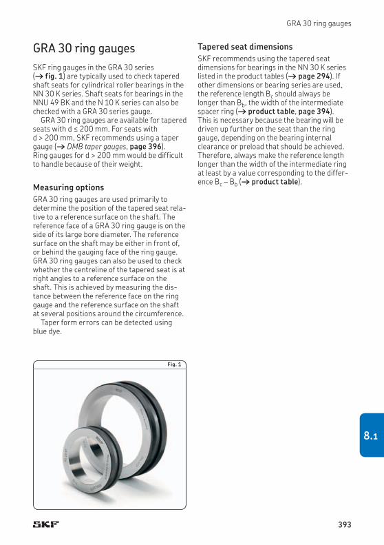
GRA 30 ring gauges
GRA 30 ring gaugesSKF ring gauges in the GRA 30 series († fig. 1) are typically used to check tapered shaft seats for cylindrical roller bearings in the NN 30 K series. Shaft seats for bearings in the NNU 49 BK and the N 10 K series can also be checked with a GRA 30 series gauge.
GRA 30 ring gauges are available for tapered seats with d ≤ 200 mm. For seats with d > 200 mm, SKF recommends using a taper gauge († DMB taper gauges, page 396). Ring gauges for d > 200 mm would be difficult to handle because of their weight.
Measuring optionsGRA 30 ring gauges are used primarily to determine the position of the tapered seat rela-tive to a reference surface on the shaft. The reference face of a GRA 30 ring gauge is on the side of its large bore diameter. The reference surface on the shaft may be either in front of, or behind the gauging face of the ring gauge. GRA 30 ring gauges can also be used to check whether the centreline of the tapered seat is at right angles to a reference surface on the shaft. This is achieved by measuring the dis-tance between the reference face on the ring gauge and the reference surface on the shaft at several positions around the circumference.
Taper form errors can be detected using blue dye.
Fig. 1
Tapered seat dimensionsSKF recommends using the tapered seat dimensions for bearings in the NN 30 K series listed in the product tables († page 294). If other dimensions or bearing series are used, the reference length Bc should always be longer than Bb, the width of the intermediate spacer ring († product table, page 394). This is necessary because the bearing will be driven up further on the seat than the ring gauge, depending on the bearing internal clearance or preload that should be achieved. Therefore, always make the reference length longer than the width of the intermediate ring at least by a value corresponding to the differ-ence Bc – Bb († product table).
393
8.1

NN 3005 K 25,1 27 4 4,2 ±0,1 19 25 46 16 0,13 GRA 3005
NN 3006 KTN 30,1 32 6 6,2 ±0,1 24 30 52 19 0,18 GRA 3006
NN 3007 K 35,1 37 6 6,2 ±0,1 25 35 57 20 0,21 GRA 3007
NN 3008 KTN 40,1 42 8 8,2 ±0,1 28 40 62 21 0,26 GRA 3008
NN 3009 KTN 45,1 47 8 8,2 ±0,1 30 45 67 23 0,31 GRA 3009
NN 3010 KTN 50,1 52 8 8,2 ±0,1 30 50 72 23 0,34 GRA 3010
NN 3011 KTN 55,15 57 8 8,3 ±0,12 32,5 55 77 26 0,42 GRA 3011
NN 3012 KTN 60,15 62 10 10,3 ±0,12 34,5 60 82 26 0,45 GRA 3012
NN 3013 KTN 65,15 67 10 10,3 ±0,12 34,5 65 88 26 0,51 GRA 3013
NN 3014 KTN 70,15 73 10 10,3 ±0,12 38,5 70 95 30 0,69 GRA 3014
NN 3015 KTN 75,15 78 10 10,3 ±0,12 38,5 75 100 30 0,73 GRA 3015
NN 3016 KTN 80,15 83 12 12,3 ±0,12 44,5 80 105 34 0,88 GRA 3016
NN 3017 KTN9 85,2 88 12 12,4 ±0,15 44 85 112 34 1 GRA 3017
NN 3018 KTN9 90,2 93 12 12,4 ±0,15 47 90 120 37 1,3 GRA 3018
NN 3019 KTN9 95,2 98 12 12,4 ±0,15 47 95 128 37 1,55 GRA 3019
NN 3020 KTN9 100,2 103 12 12,4 ±0,15 47 100 135 37 1,7 GRA 3020
NN 3021 KTN9 105,2 109 12 12,4 ±0,15 51 105 142 41 2,1 GRA 3021
NN 3022 KTN9 110,25 114 12 12,5 ±0,15 54,5 110 150 45 2,6 GRA 3022
NN 3024 KTN9 120,25 124 15 15,5 ±0,15 58,5 120 162 46 3,05 GRA 3024
NN 3026 KTN9 130,25 135 15 15,5 ±0,15 64,5 130 175 52 3,95 GRA 3026
db
d1
da
Bc
Bb
Bd
d
B
Bearing Bearing seat Ring gaugeDesignation Dimensions Dimensions Mass Designation
da db Bb Bc Bd d d1 BNom-inal
Toler-ance
– mm mm kg –
8.1 GRA 30 ring gaugesd 25 – 200 mm
394

NN 3028 K 140,3 145 15 15,6 ±0,15 65 140 188 53 4,75 GRA 3028
NN 3030 K 150,3 155 15 15,6 ±0,15 68 150 200 56 5,6 GRA 3030
NN 3032 K 160,3 165 15 15,6 ±0,15 72 160 215 60 6,8 GRA 3032
NN 3034 K 170,3 176 15 15,6 ±0,15 79 170 230 67 8,8 GRA 3034
NN 3036 K 180,35 187 20 20,7 ±0,15 90,5 180 245 74 11,5 GRA 3036
NN 3038 K 190,35 197 20 20,7 ±0,18 91,5 190 260 75 13 GRA 3038
NN 3040 K 200,35 207 20 20,7 ±0,18 98,5 200 270 82 15 GRA 3040
Bearing Bearing seat Ring gaugeDesignation Dimensions Dimensions Mass Designation
da db Bb Bc Bd d d1 BNom-inal
Toler-ance
– mm mm kg –
395
8.1

Gauges
DMB taper gauges SKF taper gauges in the DMB series enable a quick and accurate check of the diameter and the angle of external tapers. They are suitable for final checks as well as for intermediate checks during machining. DMB taper gauges are available for tapered seats from d = 40 to 360 mm.
DMB taper gauges († fig. 2) consist of:
• two saddles (a), firmly joined together at a fixed distance
• a gauge pin (b), positioned in each of the saddles
• two adjustable radial stops (c and d), in each saddle at 90° intervals from the gauge pin
• an axial stop (e) to locate the gauge axially on the taper
The gauge pins and the radial stops can be set to measure any taper angle between 0° and 6° and any diameter within the range of the gauge. Markings on the scales show the set-tings for 1:12 and 1:30 tapers.
As standard, DMB taper gauges are supplied together with two dial indicators. Tailored ref-erence tapers can be supplied on request.
MeasuringSet the radial stops and straight edges of the gauge pins to the desired diameter and taper angle, using the scales. Then, adjust the axial stop on the taper to be measured. Put the gauge on a reference taper and set the dials to zero. The gauge is now ready to take measurements.
To take a measurement, put the DMB taper gauge on the taper to be measured, making sure that it is up against the axial stop. Then take a reading. The readings on the dials are the diameter deviations. A difference in the readings between the two dials indicates a deviation in the taper angle.
While measuring, the gauge should be inclined at about 10° from the horizontal plane († fig. 3). In this position, the gauge is located on the taper by the radial and axial stops.
AccuracyThe measuring accuracy of DMB taper gauges is within 1 µm for d ≤ 280 mm and within 1,5 µm for d > 280 mm.
Fig. 2
a
c
d
e
b
396

DMB taper gauges
10°
Fig. 3
397
8.2

40 55 36 18 28 140 320 2,5 DMB 4/5,5
50 85 38 20 30 160 350 2,5 DMB 5/8,5
80 120 48 30 40 190 380 3 DMB 8/12
120 160 58 40 50 190 425 3,5 DMB 12/16
160 200 74 50 64 190 465 4,5 DMB 16/20
200 240 84 60 74 215 505 5,5 DMB 20/24
240 280 99 75 89 240 540 7 DMB 24/28
280 320 114 90 104 265 590 8,5 DMB 28/30
320 360 114 90 104 290 640 10 DMB 32/36
d
A2
A1
H
L A
8.2 DMB taper gaugesd 40 – 360 mm
Taper Taper gaugeDiameter Dimensions Mass Designation
d A A1 A2 H Lfrom to
mm mm kg –
398

399
8.2

Gauges
GB 30 and GB 10 internal clearance gaugesSKF internal clearance gauges in the GB 30 and GB 10 series are designed for use with double row cylindrical roller bearings ranging from NN 3006 K to NN 3068 K (GB 30 gauges) and for use with single row cylindrical roller bearings ranging from N 1010 K to NN 1020 K (GB 10 gauges). In general, gauges in the GB 30 series can also be used for single row bearings in the N 10 K series. GB 30 and GB 10 internal clearance gauges are able to accu-rately measure the outside envelope diameter of the roller set when the rollers are in contact with the inner ring raceway.
Depending on their size, GB 30 and GB 10 internal clearance gauges consist of either a two piece or a slotted gauge body that holds two diametrically opposed ground gauging zones († fig. 4). The gauge body can be expanded by means of an adjustment screw. This enables the gauge to be pushed over the
inner ring with roller and cage assembly, with-out damaging the rollers or the gauging zones. The gauging zone that is connected to one half of the gauge body transmits the diameter measured by both gauging zones to a dial indicator.
Fig. 4
GB 3006 … GB 3020GB 1010 … GB 1020
GB 3021 … GB 3068
400

GB 30 and GB 10 internal clearance gauges
GaugingThe typical gauging procedure:
1 Set a bore gauge to the raceway diameter of the mounted outer ring and zero the dial indicator.
2 Place the bore gauge in the centre of the gauging zone of the GB 30 or GB 10 gauge. Adjust the GB 30 or GB 10 gauge until the bore gauge indicates zero minus the correc-tion value listed in the GB 30 or GB 10 user instructions.
3 Further adjust the GB 30 or GB 10 gauge by increasing the gauge dimension by the value of the desired preload or reduce it by the desired clearance. Zero the dial indicator on the GB 30 or GB 10.
4 Place the bearing inner ring and roller set assembly onto the tapered shaft seat. Place the GB 30 or GB 10 gauge over the rollers and drive the inner ring up on the tapered seat until the dial indicator on the GB 30 or GB 10 reads zero.
For additional information, refer to Mounting on page 280.
AccuracyThe accuracy of GB 30 and GB 10 gauges is within 1 µm for sizes ≤ 20 (GB 3006 to GB 3020 and GB 1010 to GB 1020) and within 2 µm for sizes ≥ 21 (GB 3021 to GB 3068).
401
8.3

NN 3006 KTN 107 175 36 2 GB 3006
NN 3007 K 112 180 37 2 GB 3007
NN 3008 KTN 117 185 39 2 GB 3008
NN 3009 KTN 129 197 40 2,5 GB 3009
NN 3010 KTN 134 202 40 2,5 GB 3010N 1010 K 134 207 33 2 GB 1010
NN 3011 KTN 144 212 43 3,5 GB 3011N 1011 K 144 217 35 2,3 GB 1011
NN 3012 KTN 152 222 44 4 GB 3012N 1012 K 152 225 36 2,7 GB 1012
NN 3013 KTN 157 225 44 4 GB 3013N 1013 K 157 230 36 3 GB 1013
NN 3014 KTN 164 232 48 5 GB 3014N 1014 K 164 237 38 3,2 GB 1014
NN 3015 KTN 168 236 48 5 GB 3015N 1015 K 168 241 38 3,4 GB 1015
NN 3016 KTN 176 244 52 6 GB 3016N 1016 K 176 249 40 4 GB 1016
NN 3017 KTN9 185 253 53 6,5 GB 3017N 1017 K 185 258 41 4,5 GB 1017
NN 3018 KTN9 198 266 56 8 GB 3018N 1018 K 198 271 43 5,5 GB 1018
NN 3019 KTN9 203 271 56 9 GB 3019N 1019 K 203 276 43 5,8 GB 1019
NN 3020 KTN9 212 280 56 9 GB 3020N 1020 K 212 285 43 6,5 GB 1020
GB 3006 … GB 3020 GB 3021 … GB 3068
GB 1010 … GB 1020
H
L A
H
AL
8.3 GB 30 and GB 10 internal clearance gauges for cylindrical roller bearingsNN 3006 KTN – NN 3068 KN 1010 K – N 1020 K
Bearing Internal clearance gaugeDesignation Dimensions Mass Designation
L H A
– mm kg –
402

NN 3021 KTN9 322 350 46 10,5 GB 3021
NN 3022 KTN9 332 362 46 11 GB 3022
NN 3024 KTN9 342 376 48 12 GB 3024
NN 3026 KTN9 364 396 54 13 GB 3026
NN 3028 K 378 410 54 14,5 GB 3028
NN 3030 K 391 426 58 15 GB 3030
NN 3032 K 414 446 60 16 GB 3032
NN 3034 K 430 464 62 17 GB 3034
NN 3036 K 454 490 70 17,5 GB 3036
NN 3038 K 468 504 70 18 GB 3038
NN 3040 K 488 520 74 19 GB 3040
NN 3044 K 575 514 85 26 GB 3044
NN 3048 K 605 534 87 28 GB 3048
NN 3052 K 654 580 104 41 GB 3052
NN 3056 K 680 607 106 45 GB 3056
NN 3064 K 725 640 122 60 GB 3064
NN 3068 K 738 665 122 64 GB 3068
Bearing Internal clearance gaugeDesignation Dimensions Mass Designation
L H A
– mm kg –
403
8.3

Gauges
GB 49 internal clearance gauges SKF internal clearance gauges in the GB 49 series are designed for use with double row cylindrical roller bearings ranging from NNU 4920 BK to NNU 4960 BK. GB 49 series internal clearance gauges are able to ac cur-ate ly measure the internal envelope diameter of the roller set when the rollers are in contact with the outer ring raceway.
Depending on their size, GB 49 internal clearance gauges are available in two different designs († fig. 5). They have a slotted gauge body, so that both gauging ring halves can be brought to bear on the roller set with the appropriate pressure, as a result of the inher-ent resilience of the material. The outside cylindrical surface of the gauging ring has two diametrically opposed ground gauging zones. The gauge body can be compressed by means of an adjustment screw. This enables the gauge to be positioned inside the roller set
without damaging the rollers or the gauging zones.
Fig. 5
GB 4920 … GB 4938 GB 4940 … GB 4960
404

GB 49 internal clearance gauges
GaugingThe typical gauging procedure:
1 Insert the GB 49 gauge in the outer ring and roller assembly and loosen the adjustment screw until the two gauging ring halves are in contact with the roller set.
2 Set the dial indicator on the GB 49 gauge to zero.
3 Compress GB 49 using adjustment screw and remove from outer ring assembly.
4 Reset GB 49 so that dial indicator reads zero again using adjustment screw.
5 Set a stirrup gauge to GB 49 gauge diameter setting the stirrup gauge dial indicator to zero.
6 Drive the inner ring up onto its tapered seat monitoring the diameter expansion with the stirrup gauge until the dial indicator reads zero plus the desired preload or zero minus the desired clearance.
For additional information, refer to Mounting on page 280.
AccuracyThe accuracy of GB 49 gauges is within 1 µm for sizes ≤ 38 (GB 4920 to GB 4938) and within 2 µm for sizes ≥ 40 (GB 4940 to GB 4960).
405
8.4

NNU 4920 BK/SPW33 128 138 2,5 GB 4920
NNU 4921 BK/SPW33 128 143 3 GB 4921
NNU 4922 BK/SPW33 128 148 3 GB 4922
NNU 4924 BK/SPW33 133 162 3,5 GB 4924
NNU 4926 BK/SPW33 138 176 4 GB 4926
NNU 4928 BK/SPW33 138 186 4,5 GB 4928
NNU 4930 BK/SPW33 148 204 6 GB 4930
NNU 4932 BK/SPW33 148 212 6,5 GB 4932
NNU 4934 BK/SPW33 148 224 8 GB 4934
NNU 4936 BK/SPW33 157 237 9,5 GB 4936
NNU 4938 BK/SPW33 157 248 10,5 GB 4938
NNU 4940 BK/SPW33 105 263 12 GB 4940
NNU 4944 BK/SPW33 105 283 13 GB 4944
NNU 4948 BK/SPW33 105 303 14 GB 4948
NNU 4952 BK/SPW33 120 340 15 GB 4952
NNU 4956 BK/SPW33 120 360 17 GB 4956
NNU 4960 BK/SPW33 135 387 19 GB 4960
H
A A
H
Bearing Internal clearance gaugeDesignation Dimensions Mass Designation
A H
– mm kg –
8.4 GB 49 internal clearance gauges for cylindrical roller bearingsNNU 4920 BK/SPW33 – NNU 4960 BK/SPW33
GB 4920 … GB 4938 GB 4940 … GB 4960
406

407
8.4

Indexes
Text index . . . . . . . . . . . . . . . . . . . . . . . . 409
Product index . . . . . . . . . . . . . . . . . . . . . 420
408

Text index
A
A angular contact ball bearings 197axial-radial cylindrical roller bearings 333double direction angular contact thrust ball bearings 303, 311thrust bearings for screw drives 342, 364–365
AC 130, 196 ACB 196 accuracy
of bearings 24–25of seats and abutments 75–77, 325–326of seats and abutments (for screw drives) 349tolerance symbol definitions 48–49
ACD 196 ACE 196 acrylonitrile-butadiene rubber (NBR) 56adapter sleeves 376adjusting
angular contact ball bearings 166–172, 192cylindrical roller bearings 278–279, 280–283, 392precision lock nuts 380–381
ageing 55–56, 101, 114, 125air flow
effect on relubrication interval 109in an external sealing arrangement 96in an oil-air lubrication system 121
aluminium thickeners 110ambient temperature
considerations when selecting a grease 99effect on bearing speed capability 39
angular contact ball bearings 127–261adjustment during mounting 166–172, 192applications 58–64, 131–132assortment 128–129axial displacement 31, 69, 91, 166bearing arrangements 141–144cages 134–135contact angles 130–131designation system 196–197designs and variants 21, 128–141dimension series 27, 129, 130dimension standards 146direct oil-air lubrication variants 120, 136–140dismounting 124equivalent bearing loads 190–191fits 71–74fitting and clamping bearing rings 183–189high-capacity bearings 129, 131high-speed design bearings 129, 132hybrid bearings 133, 141, 167, 198–261initial grease fill 101–102, 105lifting forces 91–92load carrying capacity 30, 189location 183–189lubrication (grease) 99–112, 136, 192lubrication (oil) 113–122, 136–140, 192
markings 145, 194matched sets 141–144mounted with spacer rings 166–172, 192–193mounting 123, 136, 145, 194oil nozzle positions 118, 199–261ordering possibilities 141preload 50, 69, 90–93, 151–172product table 198–261reference grease quantities 102, 199–261relubrication intervals 106–109reuse 124sealed bearings 136, 192speeds 28–29, 38–40, 42, 192–193spring-loaded 64, 90, 93, 165, 190stiffness 67–69, 173–182temperature limits 136temperature rise as a function of speed 38tolerance classes and tolerances 24, 146–150universally matchable bearings 141–144, 194with NitroMax steel rings 52–53, 141
angular contact thrust ball bearings cartridge units (for screw drives) 342–343, 372–373designs and variants 21–22double direction bearings 301–317double direction bearings (for screw drives) 341, 368–371single direction bearings (for screw drives) 340, 366–367
angularity 76anhydrous hydrofluorides 56annular grooves
in angular contact ball bearings 120, 136–140in cylindrical roller bearings 266in double direction angular contact thrust ball bearings
303–304in shafts 96–97in thrust bearings for screw drives 341
applications for angular contact ball bearings 58–64, 131–132for axial-radial cylindrical roller bearings 320for cylindrical roller bearings 57–59, 62for double direction angular contact thrust ball bearings 57,
59for thrust bearings for screw drives 350–351machine tools 57–64
associated components 20accuracy of seats and abutments 75–77, 325–326accuracy of seats and abutments (for screw drives) 349provisions for mounting and dismounting 88–89
attachment bolts for axial-radial cylindrical roller bearings 330–332, 335for thrust bearings for screw drives 371, 373
attainable speeds 28, 44with grease lubrication 42–43, 45with oil lubrication 40–41, 45
axial clamping forces 184, 186–188axial displacement
considerations when selecting a bearing 31considerations when selecting a fit 70, 72in angular contact ball bearings 31, 69, 91, 166
Note: Designation prefixes and suffixes are shown in bold.
409
9

Indexes
in cylindrical roller bearings 31, 264, 269, 280axial drive-up 278–279, 280, 284axial fitting forces 184, 186–188axial location 78–87
with precision lock nuts 78, 375–389with stepped sleeves 79, 80–87
axial locking screws 377, 378, 381axial preload
in angular contact ball bearings 151–172in axial-radial cylindrical roller bearings 322–323in double direction angular contact thrust ball bearings 308in thrust bearings for screw drives 355–357, 358
axial stiffness of angular contact ball bearings 173–182of axial-radial cylindrical roller bearings 322–323of cylindrical roller bearings 275–276of double direction angular contact thrust ball bearings 309of thrust bearings for screw drives 339, 356–359of typical spindle bearing systems 67
axial-radial cylindrical roller bearings 319–335applications 320associated components 324–326, 330attachment bolts 330–332, 335bearing damage 322cages 320designation system 333designs and variants 22, 320dimension standards 321equivalent bearing loads 327fits 324–326friction 322–323, 330load carrying capacity 30, 322, 327, 328–329lubrication 320, 324mounting 330–332preload 322–323, 324product table 334–335retaining bolts 330, 335running-in 324stiffness 322–323storage 330temperature limits 324tightening torques 332tolerance classes and tolerances 24, 321transport 330unloading forces 322–323
B
B angular contact ball bearings 196–197axial-radial cylindrical roller bearings 333cylindrical roller bearings 286double direction angular contact thrust ball bearings 303, 311thrust bearings for screw drives 365
back-to-back arrangements with angular contact ball bearings 142–144with double direction angular contact thrust ball bearings 303with thrust bearings for screw drives 341, 342–343,
346–348ball screw support bearings † thrust bearings for screw drivesbarium thickeners 110base oil viscosity † viscositybasic dynamic load rating 33basic rating life 34basic static load rating 36bearing damage
contamination 124creep 70false brinelling 100fracture 52skid smearing 133, 268, 304, 322
bearing systems 57black-oxide 342blue dye 393
boat gyrostabilizers 131bolt mounting
with cartridge units (for screw drives) 342–343, 372–373with double direction bearings (for screw drives) 341,
370–371bolts
attachment bolts 330–332, 335, 371, 373retaining bolts 330, 335
bore gauges 282, 401boring machines 131brass
cages in angular contact ball bearings 134–135cages in cylindrical roller bearings 265, 267cages in double direction angular contact thrust ball bearings
304–305material properties 55
C
C angular contact ball bearings 130, 196–197double direction angular contact thrust ball bearings 311thrust bearings for screw drives 364
C2 273, 286 C3 273, 286 cages
function 23in angular contact ball bearings 134–135in axial-radial cylindrical roller bearings 320in cylindrical roller bearings 264, 267, 268, 280in double direction angular contact thrust ball bearings
304–305in thrust bearings for screw drives 344materials 51, 55
calcium thickeners compatibility 110considerations when selecting a grease 99–100
car wheels † racing car wheelscarbon fibre reinforced cages 55
in angular contact ball bearings 134–135in cylindrical roller bearings 264, 267
cartridge units 342–343, 372–373applications 350–351compared to other bearings for screw drives 339designation system 364–365designs and variants 22, 342–343dimension standards 353frictional moment 359–360location 342preload 355product table 372–373sealing solutions 344–345speeds 344, 363stiffness 358–359surface treatment 342temperature limits 344–345tolerance classes and tolerances 353–354
CB 196 CD 196 CE 196 centrifugal forces
in angular contact ball bearings 132, 162, 166, 167in hybrid bearings 34, 37
ceramics 54chamfer dimensions 46–47
maximum chamfer dimension limits 47, 50tolerance symbol definitions 48
churning 111, 113circulating oil 113, 114, 121clay 110clearance
in housing seats 30, 74, 302internal clearance 50–51
CN 273, 286
Note: Designation prefixes and suffixes are shown in bold.
410
CNC lathe spindles 57–58coefficient of thermal expansion
effect on preload 162of NitroMax steel 53of silicon nitride versus steel 54
collars † spacer sleevescollectors 96–97consistency grades † NLGI consistency gradescontact angles
effect on lifting force 91–92effect on load carrying capacity 30effect on speed capability 30effect on stiffness 26, 68–69in angular contact ball bearings 130–131in double direction angular contact thrust ball bearings 303in thrust bearings for screw drives 340–341
contact seals in external sealing arrangements 98in thrust bearings for screw drives 32, 344–345
contamination bearing damage 124effect on relubrication interval 109ISO oil contamination levels 122protection prior to / during mounting 123, 125protection with grease 99protection with oil 114, 116protection with seals 32, 95–98
coolants 23, 51, 122cooling 39, 99, 113, 116corrosion resistance
of NitroMax steel 52–53protection prior to mounting 125protection with grease 100–101
cotton fabric reinforced cages 55in angular contact ball bearings 134–135
creep 70cross sectional height
considerations when selecting a bearing 27effect on speed capability 38
cutting fluids 96, 106, 122cyclic operation 35, 106cylindrical roller bearings 263–299
adjustment during mounting 278–279, 280–283, 392applications 57–59, 62axial displacement 31, 264, 269, 280axial drive-up 278–279, 280, 284cages 264, 267, 268, 280design considerations 278–280designation system 286designs and variants 21, 264–268dimension standards 269dismounting 124double row bearings 265–267, 294–299equivalent bearing loads 277finish-grinding allowances 267fits 71–72, 74flanges 264gauges for checking tapered seats 391–407hybrid bearings 268, 288–293identification numbers 273, 280in combination with double direction bearings 302–303initial grease fill 101, 103, 105internal clearance 273–274, 275, 278–279load carrying capacity 30lubrication features 266, 268markings 273, 280mounted with spacer rings 78, 282–285mounting 278–279, 280–285, 401, 405oil nozzle positions 119, 266, 289–299preload 50–51, 94, 275, 278product tables 288–299reference grease quantities 103, 289–299relubrication 106–109, 266reuse 124single row bearings 264, 288–293speeds 28, 40, 42, 264, 268, 277
stiffness 275–276temperature rise as a function of speed 38tolerance classes and tolerances 24, 269–272with a pre-ground raceway 267with a tapered bore 264–265, 272
D
D 196–197DB
angular contact ball bearings 144, 197double direction angular contact thrust ball bearings 311thrust bearings for screw drives 342–343, 348, 365
DBA 308, 310, 311 DBB 308, 310, 311 deflection 66, 68density 37, 54designation systems
for angular contact ball bearings 196–197for axial-radial cylindrical roller bearings 333for cylindrical roller bearings 286for double direction angular contact thrust ball bearings 311for precision lock nuts 382for thrust bearings for screw drives 364–365
DF angular contact ball bearings 144, 197thrust bearings for screw drives 342–343, 348, 365
dial indicators on internal clearance gauges 282–284, 400–401on taper gauges 396
diameter series † ISO diameter seriesdielectric strength 54dimension series † ISO dimension seriesdimension standards 46dimensional accuracy
of bearings 24–25of seats and abutments 71–74, 325–326of seats and abutments (for screw drives) 349tolerance symbol definitions 48–49
dimensional stability † heat stabilizationdirect oil-air lubrication 120
bearing variants and dimensions 136–140dismounting 123–124
angular contact ball bearings 124cylindrical roller bearings 124design considerations 88–89thrust bearings for screw drives 341
dismounting fluids 87distance rings 278distance sleeves 86double direction angular contact thrust ball bearings 301–317
applications 57, 59basic design bearings 302–303, 312–317cages 304–305contact angles 303designation system 311designs and variants 21–22, 302–305dimension standards 306equivalent bearing loads 310fits 71–72, 74, 308high-speed design bearings 302–303, 312–317hybrid bearings 304, 312–317identification/serial numbers 305in combination with cylindrical roller bearings 302–303initial grease fill 101, 104–105lifting forces 94load carrying capacity 30lubrication (oil) 116–117, 119lubrication features 303–304markings 305mounting 123, 305, 310oil nozzle positions 119, 313–317preload 50, 94, 308product tables 312–317
Note: Designation prefixes and suffixes are shown in bold.
411
9

Indexes
radial clearance in the housing 30, 74, 302reference grease quantities 104, 313–317relubrication intervals 106–109speeds 38, 41, 43, 310stiffness 67, 309temperature rise as a function of speed 38tolerance classes and tolerances 24, 306–307
double direction angular contact thrust ball bearings (for screw drives) 341, 368–371
compared to other bearings for screw drives 339designation system 364–365dimension standards 353for bolt mounting 341, 370–371frictional moment 357, 360preload 355, 357product tables 368–371sealed bearings 344–345speeds 344, 363stiffness 357–358temperature limits 344–345tolerance classes and tolerances 353–354
double direction bearings 301–317for screw drives 341, 368–371
double row cylindrical roller bearings 265, 294–299applications 57axial displacement 264, 269, 280axial drive-up 278–279cages 267compared to single row cylindrical roller bearings 264designs and variants 21, 265–267dimension standards 269equivalent bearing loads 277finish-grinding allowances 267gauges for checking tapered seats 391–407hybrid bearings 268initial grease fill 101, 103, 105internal clearance 273–274, 275, 278mounting 280–285, 401, 405oil nozzle positions 119, 266, 295–299preload 275, 278product tables 294–299reference grease quantities 103speeds 264, 268, 277stiffness 275–276tolerance classes and tolerances 24, 269–272
drainage for oil-air lubrication 117in a multi-stage labyrinth sealing arrangement 96–97
drilling heads 60, 131, 132, 166drive-up † axial drive-upDT
angular contact ball bearings 144, 197thrust bearings for screw drives 348, 365
dust effect on relubrication interval 109protection prior to / during mounting 123
dynamometers 131
E
E 196eccentric loads 327elastic deformation 66, 68elasto-hydrodynamic lubrication (EHL) 100electrical resistivity 54electro-spindles
oil cleanliness requirements 122with angular contact ball bearings 62–64, 132with cylindrical roller bearings 62, 264
ellipse truncation 36end plates 183–189envelope diameters 280, 392, 400, 404envelope requirement † ISO envelope requirement environmental considerations
for fluoro rubber (FKM) 56for oil mist lubrication 115for oil-air lubrication 116
EP additives compatibility 55, 100considerations for grease lubrication 99–100considerations for oil lubrication 121
equivalent bearing loads dynamic 33static 36
ester oils compatibility 109in sealed bearings 104
esters 56ethers 56external seals 95–98extreme pressure additives † EP additives
F
F 130, 196–197face-to-face arrangements
with angular contact ball bearings 142–144with thrust bearings for screw drives 342–343, 346–348
false brinelling 100fatigue strength 52–53, 141FB 196 FE 196 filtering 114, 117finish-grinding allowances
for inner rings of cylindrical roller bearings 267for spacer rings for angular contact ball bearings 166–172
fits axial location 78–79effect of surface roughness 75effect on preload and internal clearance 50–51, 90, 94effect on stiffness 68for housings 72–74, 326for shafts 71, 73–74, 325radial location 70
FKM † fluoro rubber (FKM)flanged housings 342–343, 372–373fluoro rubber (FKM)
material properties 56seals for angular contact ball bearings 136
fracture 52friction 37
effect of preload and internal clearance 37effect on speed capability 38–39generated by seals 96, 98with grease lubrication 37, 100, 111with hybrid bearings 37with oil lubrication 113–115
frictional losses 53, 99, 113frictional moment
in axial-radial cylindrical roller bearings 322–323in thrust bearings for screw drives 357, 360with grease lubrication 111
G
G angular contact ball bearings 142, 196axial-radial cylindrical roller bearings 320, 324, 333
G… angular contact ball bearings 151, 197double direction angular contact thrust ball bearings 311thrust bearings for screw drives 355, 364–365
GA angular contact ball bearings 196thrust bearings for screw drives 364
gauge blocks 282–283
Note: Designation prefixes and suffixes are shown in bold.
412

gauges 391–407bore gauges 282for mounting cylindrical roller bearings 280–283internal clearance gauges 280–283, 400–407ring gauges 393–395taper gauges 396–399
GB angular contact ball bearings 196thrust bearings for screw drives 364
GC 196 GD 196 geometrical accuracy
of seats and abutments 75–77, 325–326of seats and abutments (for screw drives) 349
glass fibre reinforced cages in angular contact ball bearings 134–135in cylindrical roller bearings 264, 267, 268material properties 55
GMM 342, 365 grease fills
effect on friction 37in sealed angular contact ball bearings 136in sealed thrust bearings for screw drives 344initial grease fill 101–105
grease lubrication 99–112attainable speeds 42–43compared with oil lubrication (speed capability) 45initial grease fill 101–105relubrication 106–109running-in 111–112service life 106
greases in sealed bearings 104selection criteria 99–100SKF greases 99storage 122thickener compatibility 110
grinding allowances † finish-grinding allowancesgrinding machines 64, 93, 131, 132grub (set) screws
in double direction angular contact thrust ball bearings 341in precision lock nuts 378, 380, 384–388in thrust bearings for screw drives 341
H
H 120, 137–139, 197H1 120, 137–139, 197 hammers 380hardness
of bearing steel 51, 54of NitroMax steel 53of silicon nitride 54
HC angular contact ball bearings 133, 197double direction angular contact thrust ball bearings 304, 311
HC5 268, 286 heat stabilization 51, 53heat treatment
of carbon chromium steel 51of NitroMax steel 52–53
heating bearings † hot mountinghollow shafts
fits 71with cylindrical roller bearings 279with stepped sleeves 81, 84
hot mounting 123–124angular contact ball bearings 194sealed bearings 136, 345
housing covers 79in a multi-stage labyrinth sealing arrangement 96–97
humidity 125hybrid bearings
angular contact ball bearings 133, 141, 167, 198–261
basic static load rating 36cylindrical roller bearings 268, 288–293double direction angular contact thrust ball bearings 304,
312–317effect on relubrication interval 106–108frictional behaviour 37material properties 54rating life 34speeds 38, 40–43with NitroMax steel rings 52–53, 141
hydraulic nuts 86hydrocarbons 56
I
identification numbers on cylindrical roller bearings 273, 280on double direction angular contact thrust ball bearings 305
immersion 106impact toughness 52–53indexing heads 320induction heaters 123
for heating sealed bearings 136, 345for mounting axial-radial cylindrical roller bearings 330
initial grease fills 101–105injectors 116–117installation 123–124
of precision lock nuts 379–381of stepped sleeves 86–87, 123–124
integral seals design considerations 98in angular contact ball bearings 136in thrust bearings for screw drives 344–345types and designs 32
interference fits 71axial location 78–79effect on preload and internal clearance 50–51for angular contact ball bearings 74for cylindrical roller bearings 31, 74for stepped sleeves 80–81, 84radial location 70
internal clearance 50–51effect on friction 37in cylindrical roller bearings 273–274, 275, 278–279
internal clearance gauges 280–283, 400–407internal grinding machines 64, 132, 165ISO
diameter series 27, 46dimension series 46envelope requirement 71–72general plans 46oil contamination levels 122tolerance classes 24, 73tolerance grades 77tolerance standards 46–47
IT tolerance grades 77
K
K 264–265, 286ketones 55, 56key slots 376keyways 376kinematic lubricant starvation 52, 264kinematic viscosity † viscosity
L
L 120, 137–140, 197L1 120, 139, 197
Note: Designation prefixes and suffixes are shown in bold.
413
9

Indexes
labyrinth seals in a multi-stage sealing arrangement 96–97integral to stepped sleeves 80, 84
laminar rings 339, 344–345lathes 57–58, 131, 166life 33–35lifting forces
for angular contact ball bearings 91–92for double direction angular contact thrust ball bearings 94for thrust bearings for screw drives 94, 360
linear springs † springslithium thickeners
compatibility 110considerations when selecting a grease 99–100in sealed bearings 104
live centres 59, 131loads
considerations when selecting a bearing 30effect on relubrication interval 109load ratings 33–36requisite minimum loads 34
locating/non-locating bearing systems 31location
axial 78–87radial 70–77with precision lock nuts 376–377with stepped sleeves 79, 80–87
lock nuts † precision lock nutslock washers 376locking pins 376loose fits 71
effect on stiffness 31, 68for non-locating bearings 31radial location 70
loosening torques 378lubricants
greases 99–101, 104, 110oils 121storage 122
lubricating oils † oilslubrication
grease 99–112oil 113–122
lubrication holes in angular contact ball bearings 120, 136–140in axial-radial cylindrical roller bearings 324in cylindrical roller bearings 266in double direction angular contact thrust ball bearings 304in thrust bearings for screw drives 341
lubrication intervals 117
M
M angular contact ball bearings 197double direction angular contact thrust ball bearings 304–
305, 311MA 134, 196 machine tool spindles † spindlesmachine tools
applications 57–64, 131–132considerations when selecting a bearing 23–32
machining centres with angular contact ball bearings 62–63, 131–132, 141, 166with axial-radial cylindrical roller bearings 320with cylindrical roller bearings 62
markings on angular contact ball bearings 145, 194on cylindrical roller bearings 273, 280on double direction angular contact thrust ball bearings 305on thrust bearings for screw drives 352
matched sets of angular contact ball bearings 141–144
of thrust bearings for screw drives 340, 346–348materials 51–56
for bearings 51–54for cages 55for precision lock nuts 378for seals 56
measuring systems 131medical equipment 131metal cutting machines 57–63, 132metal-to-metal contact 113microturbines 131milling machines 59, 62–63, 131–132, 141, 166mineral acids 56mineral oils 56, 99
compatibility 109minimum load 34minimum quantity lubrication (MQL)
with oil-air lubrication 116with SKF Mircrodosage system 121
misalignment 75in thrust bearings for screw drives 346
miscibility 109–110modulus of elasticity 54moisture
effect on lubricant properties 122effect on relubrication interval 109protection prior to / during mounting 123protection with grease 99protection with seals 95
moment loads on angular contact ball bearings 142, 167on axial-radial cylindrical roller bearings 327, 328–329on thrust bearings for screw drives 346
motorized spindles † electro-spindlesmounting 123–124
angular contact ball bearings 136, 145, 194axial-radial cylindrical roller bearings 330–332cylindrical roller bearings 280–285design considerations 88–89double direction angular contact thrust ball bearings 305, 310precision lock nuts 379–381stepped sleeves 86–87thrust bearings for screw drives 339, 345, 352, 362
mounting fluids 87multi-spindle heads 320
N
NBR † acrylonitrile-butadiene rubber (NBR)needle roller bearings 347NitroMax steel 52–53
in hybrid angular contact ball bearings 141NLGI consistency grades 99non-contact seals
in angular contact ball bearings 32, 136in external sealing arrangements 96–97in thrust bearings for screw drives 32, 344–345
O
oil bath 114attainable speeds 44
oil change intervals 121oil distribution grooves 89oil drop 115oil flow rates 113–114oil injection method
dimensions for ducts, grooves and holes 88–89equipment and pressure media 87for cylindrical roller bearings 285for stepped sleeves 80, 86–87
oil jet 115
Note: Designation prefixes and suffixes are shown in bold.
414

attainable speeds 44lubricating oils 121
oil lubrication 113–122compared with grease lubrication (speed capability) 45contamination levels 122effect on temperature and frictional losses 113lubricating oils 121
oil mist 115attainable speeds 44lubricating oils 121
oil nozzles 116–117for angular contact ball bearings 118, 199–261for cylindrical roller bearings 119, 266, 289–299for double direction angular contact thrust ball bearings 119,
313–317oil supply ducts 89oil-air 116–121
attainable speeds 40–41, 44direct oil-air lubrication 120, 136–140effect on bearing temperature and frictional losses 113lubricating oils 121
oils 121oil-spot † oil-airopen bearings
initial grease fill 101–105shelf life 125
open flames 56operating temperatures 37
as a function of oil quantity 113as a function of speed 38during running-in 112, 124effect on preload and internal clearance 37effect on relubrication interval 109of cage materials 55of seal materials 56
O-rings in stepped sleeves 81, 83on angular contact ball bearings 120, 136–140
oscillations considerations when selecting a grease 99with axial-radial cylindrical roller bearings 328
osculation 26, 131, 132overhung shafts 346–347, 350–351ozone 56
P
P 378, 382P2 197 P4 197 P4A 197 P4C 311 PA66 † polyamide 66 (PA66)PA9A 197 PAO 104Parallel Kinematic Machines (PKM) 131PBC 197 PBT 197 PCB drilling machines 132PE 341, 365 PEEK † polyetheretherketone (PEEK)permissible speeds 39PFC 197 PFT 197 PG 197 PHA 264, 267, 268, 286 phenolic resin
cages in angular contact ball bearings 134–135material properties 55
pin wrenches 379polishing machines 131polyamide 66 (PA66)
cages in cylindrical roller bearings 264, 267material properties 55
polyetheretherketone (PEEK) cages in angular contact ball bearings 134–135material properties 55
polyglycol 109polymers
cages in angular contact ball bearings 134–135cages in cylindrical roller bearings 264, 267, 268, 280material properties 55–56
polyphenylether 109polyurea 110precision
of bearings 24–25of seats and abutments 75–77, 325–326of seats and abutments (for screw drives) 349
precision lock nuts 78, 375–389adjustment during mounting 380–381compared with stepped sleeves 79designation system 382designs 376–377dimension standards 378installation 379–381loosening torques 378lubrication 378materials 378preload 376–377product tables 384–389removal 379–380spanners 379, 384–388thread standards 378tolerances 378with axial locking screws 377, 388–389with locking pins 376, 384–387
pre-ground raceways 267preload 90–94
effect on friction 37effect on relubrication interval 108effect on speed capability 64in angular contact ball bearings 50, 69, 90–93, 151–172in axial-radial cylindrical roller bearings 322–323, 324in cylindrical roller bearings 50–51, 94, 275, 278in double direction angular contact thrust ball bearings 50, 94,
308in precision lock nuts 376–377in thrust bearings for screw drives 50, 94, 341, 355–357, 358
preservatives 125printing machines 131protectors 381PT 197 PTFE 109pumping effects 96
Q
QBC angular contact ball bearings 144, 197thrust bearings for screw drives 342–343, 348, 365
QBT angular contact ball bearings 144, 197thrust bearings for screw drives 348, 365
QFC angular contact ball bearings 144, 197thrust bearings for screw drives 342–343, 348, 365
QFT angular contact ball bearings 144, 197thrust bearings for screw drives 348, 365
QT angular contact ball bearings 144, 197thrust bearings for screw drives 348, 365
Note: Designation prefixes and suffixes are shown in bold.
415
9

Indexes
R
racing car wheels 131radial clearance 30, 74, 288radial internal clearance 50–51
in cylindrical roller bearings 273–274, 275, 278–279radial location 70–77radial stiffness 68–69
of axial-radial cylindrical roller bearings 322–323of cylindrical roller bearings 275–276of typical spindle bearing systems 67
reconditioning 125reference grease quantities 101
for angular contact ball bearings 102, 199–261for cylindrical roller bearings 103, 289–299for double direction angular contact thrust ball bearings 104,
313–317for thrust bearings for screw drives 104, 367
reliability 34–35effect on relubrication interval 109
relubrication effect on frictional moment 37intervals and adjustments 106–109of sealed bearings 32, 101
relubrication-free 101removal
of precision lock nuts 380of stepped sleeves 80–81, 87
retaining bolts 330, 335reusing bearings 124rigidity 66–69
considerations when selecting a bearing 26, 27ring gauges 393–395robotics 131roller and cage thrust assemblies 320rotary tables 320, 324rotating outer ring loads 71–72RS 344–345, 363, 364 running accuracy
of bearings 24–25of seats and abutments 75–76, 325–326of seats and abutments (for screw drives) 349tolerance symbol definitions 49
running-in 111–112effect of grease fill on friction 37, 101, 124of axial-radial cylindrical roller bearings 324
run-out † running accuracyrust protection 100–101, 125RZ 344–345, 363, 364
S
S 136, 196safety factors † static safety factorsscrew drive bearings † thrust bearings for screw drivesscrew drives 338, 350–351sealed bearings
angular contact ball bearings 136, 192grease specifications 104shelf life 125thrust bearings for screw drives 344–345washing 136, 345
sealing solutions 32, 95–98materials 56
seats accuracy 75–77, 324–326accuracy (for screw drives) 349fits 70–74, 324–326fits (for screw drives) 349
selection criteria 20–32semiconductor industry 61, 131serial numbers
on angular contact ball bearings 145
on double direction angular contact thrust ball bearings 305service life
of bearings with NitroMax steel rings 52of grease 99, 106of hybrid bearings 34, 37, 52
set screws † grub (set) screwssets
of angular contact ball bearings 141–144of thrust bearings for screw drives 340, 346–348
shaft orientation considerations for oil-air lubrication 117considerations when selecting a grease 99–100effect on relubrication interval 109
shaft systems 20shelf life 125shock loads
considerations for life calculations 35considerations when selecting a grease 98–99permissible static loads 36suitability of preloading with springs 93
silicon nitride (Si3N4) in hybrid angular contact ball bearings 133in hybrid cylindrical roller bearings 268in hybrid double direction angular contact thrust ball bearings
304material properties 54
silicon wafer chips 61silicone-methyl 109silicone-phenyl 109single direction angular contact thrust ball bearings (for screw
drives) 340, 366–367applications 350–351bearing arrangements 346–348compared to other bearings for screw drives 339designation system 364–365designs and variants 22, 340dimension standards 353frictional moment 356, 360in cartridge units 342–343, 372–373load carrying capacity 356, 361preload 355–356product table 366–367reference grease quantities 104, 367sealed bearings 344–345sets 340, 346–348speeds 344, 363stiffness 356, 358temperature limits 344–345tolerance classes and tolerances 24, 353–354
single direction bearings 340, 366–367in cartridge units 342–343, 372–373
single row cylindrical roller bearings 264, 288–293axial displacement 264, 269, 280axial drive-up 278–279basic design bearings 264cages 264, 267compared to double row cylindrical roller bearings 264designs and variants 264dimension standards 269equivalent bearing loads 277gauges for checking tapered seats 391–407high-speed design bearings 264hybrid bearings 268initial grease fill 101, 103, 105internal clearance 273–274, 275, 278–279lubrication features 268mounting 278–279, 401preload 275, 278product tables 288–293speeds 264, 268, 277stiffness 275–276tolerance classes and tolerances 24, 269–272
sintered steel 378, 382SKF LubeSelect 100SKF Microdosage system 121SKF Spindle Service Centres 125, 166
Note: Designation prefixes and suffixes are shown in bold.
416

SKF Spindle Simulator 33, 358skidding 90–91, 322
benefits of hybrid bearings 133, 268, 304sleeves
spacer sleeves 78stepped sleeves 79, 80–87
smearing 133, 268, 304soaps 110sodium thickeners 110SP
cylindrical roller bearings 273, 286double direction angular contact thrust ball bearings 311
spacer rings effect on running-in of bearings 111for angular contact ball bearings 166–172, 192–193for cylindrical roller bearings 78, 282–285for oil-air lubrication 116
spacer sleeves 78spacers † spacer ringsspanners 379, 384–388SPC2 273, 286 speed factor 33speeds 38–45
attainable speeds 44considerations when selecting a bearing 28for typical spindle bearing systems 45permissible speeds 39with grease lubrication 42–45with oil lubrication 40–41, 44–45
Spindle Service Centres † SKF Spindle Service CentresSpindle Simulator † SKF Spindle Simulatorspindles
applications 57–64service 125, 166
splash guards 96–97spring curves 91springs 64, 90, 93, 165stainless steels † NitroMax steelstandalone bearings 141start-up
benefits of hybrid bearings 133, 268, 304benefits of preload 90considerations when selecting a grease 100effect of grease fill 37when running in 111–112, 124
static loads 36static safety factors 36steels 51–54stepped sleeves 79, 80–87
designs 80, 84dimensions 81–83fits 80, 84installation 86–87, 123–124load carrying capacity 84–85material 84removal 87with O-ring 80, 81, 83without O-ring 80, 81–82
stiffness 66–69of angular contact ball bearings 173–182of axial-radial cylindrical roller bearings 322–323of cylindrical roller bearings 275–276of double direction angular contact thrust ball bearings 309of thrust bearings for screw drives 339, 356–359
stirrup gauges 405storage
of bearings 125, 330of lubricants 122
super-precision bearings selection criteria 20–32types and designs 21–22
surface roughness 75, 77, 325–326surface treatments 342synthetic oils
compatibility 109considerations when selecting a grease 99
effect on cage materials 55system rigidity † rigidity
T
tandem arrangements with angular contact ball bearings 142–144with thrust bearings for screw drives 346–348
taper gauges 396–399tapered bores 264–265, 272tapered seats
checking the accuracy with a ring gauge 393checking the accuracy with a taper gauge 396–397
TBT angular contact ball bearings 144, 197thrust bearings for screw drives 348, 365
telescopes 131temperatures
ambient 39operating 37
test running 124TFT
angular contact ball bearings 144, 197thrust bearings for screw drives 348, 365
thermal contraction 31thermal expansion 31
effect on preload and internal clearance 50–51, 93of silicon nitride versus steel 54
thickeners 110thin-walled rings 75, 81, 123threaded holes
in double direction angular contact thrust ball bearings 355in housings 88in shafts 89
thrust bearings axial-radial cylindrical roller bearings 319–335cartridge units (for screw drives) 342–343, 372–373double direction bearings 301–317double direction bearings (for screw drives) 341, 368–371single direction bearings (for screw drives) 340, 366–367
thrust bearings for screw drives 337–373applications 350–351associated components 349bearing arrangements 346–348cages 344cartridge units 342–343, 372–373contact angles 340, 341designation system 364–365designs and variants 22, 338–345dimension standards 353dismounting 341double direction bearings 341, 368–372equivalent bearing loads 361–362frictional moment 339, 346–360initial grease fill 101, 104–105lifting forces 94, 360load carrying capacity 30, 339, 346, 361lubrication 99, 106, 342, 344markings 352matched sets 340, 346–348misalignment 346moment stiffness 357mounting 123, 339, 345, 352, 362non-locating bearings 347preload 50, 94, 355–357, 358reference grease quantities 104, 367relubrication 106–109, 341, 344sealed bearings 339, 344–345selection criteria 339single direction bearings 340, 366–367speeds 41, 43, 339, 344, 363stiffness 339, 356–359temperature limits 344–345tolerance classes and tolerances 24, 353–354
Note: Designation prefixes and suffixes are shown in bold.
417
9

Indexes
Note: Designation prefixes and suffixes are shown in bold.
universally matchable bearings 340, 346–348, 352washing 345
tightening torques for locating angular contact ball bearings 183–189for precision lock nuts 384–388
tilting stiffness 323TN 264, 267, 286 TN9
cylindrical roller bearings 264, 267, 286double direction angular contact thrust ball bearings 304–
305, 311TNHA
angular contact ball bearings 134, 196cylindrical roller bearings 264, 267, 268, 286
tolerance classes for bearings 24–25for seats 71–74, 325–326for seats (for screw drives) 349
tolerance grades † IT tolerance gradestolerances 47
symbols and definitions 48–50tommy bars 379torque wrenches 380toughness † impact toughnesstransition fits 71trial mounting 282–285troubleshooting 124TT
angular contact ball bearings 144, 197thrust bearings for screw drives 348, 365
turbochargers 131
U
unit conversion table 10universally matchable bearings
angular contact ball bearings 141–144, 194thrust bearings for screw drives 340, 346–348, 352
unloading forces 322–323UP
cylindrical roller bearings 286double direction angular contact thrust ball bearings 311
V
V 141, 196vertical shaft arrangements
applications 61, 131–132effect on relubrication interval 109with grease lubrication 99with oil-air lubrication 117with thrust bearings for screw drives 346–347
vibrations considerations when selecting a grease 99–100troubleshooting 124
viscosity considerations when selecting a grease 99–100of grease in sealed bearings 104of lubricating oils 121of mounting and dismounting fluids 87
VR521 286 V-shaped markings
on angular contact ball bearings 145on double direction angular contact thrust ball bearings 305on thrust bearings for screw drives 352
VU001 267, 286
W
W33 cylindrical roller bearings 266, 286double direction angular contact thrust ball bearings 311
W33X 286 washing
bearings before regreasing 109sealed bearings 32, 136, 345
water considerations when selecting a grease 99–100effect on lubricant shelf life 122resistance of NBR 56wash-out 100
wear resistance of hybrid bearings 34resistance of NitroMax steel 52
width series 46woodworking machines 132
418

419
9

Designation Product Product tables No. Page1)
Product index
1) Starting page of the product table
70.. Angular contact ball bearings . . . . . . . . . . . . . . . . . . . . . . . . . . . . . . . . . . . . . . . . . . . . . . . 2.1 19870../..H Angular contact ball bearings for direct oil-air lubrication . . . . . . . . . . . . . . . . . . . . . . . . 2.1 19870../..H1 Angular contact ball bearings for direct oil-air lubrication . . . . . . . . . . . . . . . . . . . . . . . . 2.1 19870../..L Angular contact ball bearings for direct oil-air lubrication . . . . . . . . . . . . . . . . . . . . . . . . 2.1 19870../..L1 Angular contact ball bearings for direct oil-air lubrication . . . . . . . . . . . . . . . . . . . . . . . . 2.1 19870../HC Hybrid angular contact ball bearings . . . . . . . . . . . . . . . . . . . . . . . . . . . . . . . . . . . . . . . . . 2.1 19870../HC..H Hybrid angular contact ball bearings for direct oil-air lubrication . . . . . . . . . . . . . . . . . . 2.1 19870../HC..H1 Hybrid angular contact ball bearings for direct oil-air lubrication . . . . . . . . . . . . . . . . . . 2.1 19870../HC..L Hybrid angular contact ball bearings for direct oil-air lubrication . . . . . . . . . . . . . . . . . . 2.1 19870../HC..L1 Hybrid angular contact ball bearings for direct oil-air lubrication . . . . . . . . . . . . . . . . . . 2.1 198718.. Angular contact ball bearings . . . . . . . . . . . . . . . . . . . . . . . . . . . . . . . . . . . . . . . . . . . . . . . 2.1 198718../HC Hybrid angular contact ball bearings . . . . . . . . . . . . . . . . . . . . . . . . . . . . . . . . . . . . . . . . . 2.1 198719.. Angular contact ball bearings . . . . . . . . . . . . . . . . . . . . . . . . . . . . . . . . . . . . . . . . . . . . . . . 2.1 198719../..H Angular contact ball bearings for direct oil-air lubrication . . . . . . . . . . . . . . . . . . . . . . . . 2.1 198719../..H1 Angular contact ball bearings for direct oil-air lubrication . . . . . . . . . . . . . . . . . . . . . . . . 2.1 198719../..L Angular contact ball bearings for direct oil-air lubrication . . . . . . . . . . . . . . . . . . . . . . . . 2.1 198719../HC Hybrid angular contact ball bearings . . . . . . . . . . . . . . . . . . . . . . . . . . . . . . . . . . . . . . . . . 2.1 198719../HC..H Hybrid angular contact ball bearings for direct oil-air lubrication . . . . . . . . . . . . . . . . . . 2.1 198719../HC..H1 Hybrid angular contact ball bearings for direct oil-air lubrication . . . . . . . . . . . . . . . . . . 2.1 198719../HC..L Hybrid angular contact ball bearings for direct oil-air lubrication . . . . . . . . . . . . . . . . . . 2.1 19872.. Angular contact ball bearings . . . . . . . . . . . . . . . . . . . . . . . . . . . . . . . . . . . . . . . . . . . . . . . 2.1 19872../HC Hybrid angular contact ball bearings . . . . . . . . . . . . . . . . . . . . . . . . . . . . . . . . . . . . . . . . . 2.1 198
BEAM .. Double direction angular contact thrust ball bearings for bolt mounting . . . . . . . . . . . . . 6.3 370BEAS .. Double direction angular contact thrust ball bearings. . . . . . . . . . . . . . . . . . . . . . . . . . . . 6.2 368BSA 2.. Single direction angular contact thrust ball bearings . . . . . . . . . . . . . . . . . . . . . . . . . . . . 6.1 366BSA 3.. Single direction angular contact thrust ball bearings . . . . . . . . . . . . . . . . . . . . . . . . . . . . 6.1 366BSD .. Single direction angular contact thrust ball bearings . . . . . . . . . . . . . . . . . . . . . . . . . . . . 6.1 366BTM .. Double direction angular contact thrust ball bearings. . . . . . . . . . . . . . . . . . . . . . . . . . . . 4.1 312BTM ../HC Hybrid double direction angular contact thrust ball bearings . . . . . . . . . . . . . . . . . . . . . . 4.1 312BTW .. Double direction angular contact thrust ball bearings. . . . . . . . . . . . . . . . . . . . . . . . . . . . 4.1 312
DMB .. Taper gauges . . . . . . . . . . . . . . . . . . . . . . . . . . . . . . . . . . . . . . . . . . . . . . . . . . . . . . . . . . . . 8.2 398
FBSA 2.. Cartridge units with a flanged housing. . . . . . . . . . . . . . . . . . . . . . . . . . . . . . . . . . . . . . . . 6.4 372
GB 10.. Internal clearance gauges for cylindrical roller bearings. . . . . . . . . . . . . . . . . . . . . . . . . . 8.3 402GB 30.. Internal clearance gauges for cylindrical roller bearings. . . . . . . . . . . . . . . . . . . . . . . . . . 8.3 402GB 49.. Internal clearance gauges for cylindrical roller bearings. . . . . . . . . . . . . . . . . . . . . . . . . . 8.4 406GRA 30.. Ring gauges . . . . . . . . . . . . . . . . . . . . . . . . . . . . . . . . . . . . . . . . . . . . . . . . . . . . . . . . . . . . . 8.1 394
KMD .. Precision lock nuts with axial locking screws . . . . . . . . . . . . . . . . . . . . . . . . . . . . . . . . . . . 7.3 388KMT .. Precision lock nuts with locking pins. . . . . . . . . . . . . . . . . . . . . . . . . . . . . . . . . . . . . . . . . . 7.1 384KMTA .. Precision lock nuts with locking pins. . . . . . . . . . . . . . . . . . . . . . . . . . . . . . . . . . . . . . . . . . 7.2 386
N 10.. Single row cylindrical roller bearings . . . . . . . . . . . . . . . . . . . . . . . . . . . . . . . . . . . . . . . . . 3.1 288N 10../HC5 Hybrid single row cylindrical roller bearings . . . . . . . . . . . . . . . . . . . . . . . . . . . . . . . . . . . 3.1 288NN 30.. Double row cylindrical roller bearings . . . . . . . . . . . . . . . . . . . . . . . . . . . . . . . . . . . . . . . . 3.2 294NN 30../..W33(X) Double row cylindrical roller bearings with relubrication features . . . . . . . . . . . . . . . . . . 3.2 294NNU 49.. Double row cylindrical roller bearings . . . . . . . . . . . . . . . . . . . . . . . . . . . . . . . . . . . . . . . . 3.2 294NNU 49../..W33(X) Double row cylindrical roller bearings with relubrication features . . . . . . . . . . . . . . . . . . 3.2 294NRT .. Axial-radial cylindrical roller bearings . . . . . . . . . . . . . . . . . . . . . . . . . . . . . . . . . . . . . . . . 5.1 334
420

Designation Product Product tables No. Page1)
1) Starting page of the product table
S70.. Sealed angular contact ball bearings . . . . . . . . . . . . . . . . . . . . . . . . . . . . . . . . . . . . . . . . . 2.1 198S70../HC Sealed hybrid angular contact ball bearings . . . . . . . . . . . . . . . . . . . . . . . . . . . . . . . . . . . 2.1 198S719.. Sealed angular contact ball bearings . . . . . . . . . . . . . . . . . . . . . . . . . . . . . . . . . . . . . . . . . 2.1 198S719../HC Sealed hybrid angular contact ball bearings . . . . . . . . . . . . . . . . . . . . . . . . . . . . . . . . . . . 2.1 198S72.. Sealed angular contact ball bearings . . . . . . . . . . . . . . . . . . . . . . . . . . . . . . . . . . . . . . . . . 2.1 198S72../HC Sealed hybrid angular contact ball bearings . . . . . . . . . . . . . . . . . . . . . . . . . . . . . . . . . . . 2.1 198
421
9

Indexes
422