13.56 mhz rfid power systemdecade is now walmarts commitment to have rfid take over barcode scanning...
TRANSCRIPT

13.56 MHz RFID Power System
Darren Pluth Gurveer Singh
Li-Cheng Shiue Geetpal Kaur
Advisor: Dr. Raymond Kwok
May 14, 2004
1

Table of Contents
1. Abstract
2. RFID History
3. RFID System
4. Project Introduction
5. Oscillator
6. Amplifier
7. Antenna
8. Reference
2

Abstract
The RF power system consists of oscillator, amplifier, and Helmholtz antenna.
The report focuses on how low powered, low frequency RFID reader is able to detect and
identify the RF Tag at a greater distance with the assistance of the RF power system.
Since the available RFID Reader is a low power and low frequency device, it in
coordination with oscillator - providing constant sine wave at a specified frequency,
amplifier – amplifying the signal, and Helmholtz antenna – providing uniform magnetic
field between the two coiled loops is a successful RF power system. It includes
corresponding schematics from PSPICE for oscillator and amplifier with the
results/outputs obtained from oscilloscope.
3

RFID History
RFID time development started in the 1940’s and was referred to as “reflected
power communication.” During that progress was slow in the design because key
technologies were not available yet such as the transistor, integrated circuit, and
microprocessor. Most of the RFID concentration from 1950 to 1980 was based on
laboratory experiments at Universitys, and government labs. The United States
Government gave funding to Los Alamos National Laboratories to further the
development of the technology in the early 1980’s. During this time the previously stated
technologies were mature enough to support RFID’s full potential. The 1980’s saw
commercialization of the technology on a small scale; this was because the technology
was so expensive.
The focus of RFID in the United States during the 1980’s was on transportation,
personal access and for animal tracking. These beginning industries were the paving
stones for the explosion of the technology in the 1990’s. During this decade the
technology was used by the US military in tracking cargo that the Airforce and Army
shipped. The technology was also implemeted on the Bay Bridge in Oakland to allow
commuters high speed access through the toll gates. The largest development in this
decade is now Walmarts commitment to have RFID take over barcode scanning
completley and automate their purchasing system. This is a large step because Walmart
is the largest retailer in the world. The timeline below shows how RFID was used around
the world based on each decade.
4

• 1940s -- RFID used in WW2 to identify ‘friend or foe’ aircraft • 1960s -- Electronic article surveillance used to counter theft – first commercial
use of RFID • 1970s -- Developers, inventors, companies, academic institutions and government
develop RFID applications • 1980s -- Europe deploys RFID for animal tracking, industrial and business
applications and payment on toll roads • 1996 -- ANA (e.centre) board and EAN International plan RFID as the next
standard data carrier1998EAN UCC RFID project kicks-off • 1999 -- EAN and UCC adopt UHF the Auto-ID Center is established to develop
the ‘internet of things’ • 2000 -- EAN UCC rolls out the GTAG project • 2002 -- E.centre leads the Home Office Chipping of Goods ‘CD.id’ project • 2003 -- EPCglobal joint venture set-up to oversee the rollout of RFID standards
worldwide • 2004 -- First EPCglobal standards are released
RFID System
RFID is a mix of Electrical Engineering disciplines to transmit digital data
through wireless transmission. The system contains three elements which are the RFID
reader/transmitter, the reader’s antenna, and the transponder. The reader/transceiver is a
device that generates the digital pulse code required to activate the transponder. The
transceiver also designates what frequency the system will operate at. The RFID system
chosen for this project is Skyetek’s M1 which has a frequency of 13.56 MHz. Based on
other industry models which are 915 MHz, 13.56 MHz is low. Since the frequency used
for this project is low, that means that the power associated with the wave is low and the
reading range will be short.
The second part of the RFID system is the transponder, which has two different
power supplies. The transponder in the system used for this project is the passive type.
This means that the transponder tag uses the energy from the transceivers transmitted
5

wave to send its coded information. The other version of the transponder is the more
costly battery powered version. This device will transmit the information for up to 4
weeks and will have a range of 30 meters.
Antenna’s used in RFID systems are based on the needs of the customer and can
range anywhere from Helmholtz to Dish style. Skyeteks RFID transceiver has a built in
antenna that is in the shape of a loop. It has a radius of about ¾ of an inch and only one
turn. The transceivers default setting is the on board antenna, but an external antenna can
be installed with the change of a jumper setting on the circuit board.
Figure1 shows what the RFID transceiver looks like.
Figure 1
6

Project Introduction
The reading range of a 13.56 MHz is RFID system is around 3cm with passive
tags. In order to increase the distance to a more usable range, an amplification system
needs to be built. The chosen system is a wireless power transfer system. The system is
designed to transmit an amplified sine wave at 13.56 MHz to the transponder. This will
theoretically allow the transponder have enough available energy to sends its coded
information a distance farther than 3 cm. The power that is transmitted is a generic signal
that places the transponder in an amplified standby state. When the transceiver sends its
information to the transponder it turns on and transmits the bits programmed into it. It
has the power of the both the generic signal and the transceivers. Figure 2 shows how the
RFID and the wireless power amplifier system will interact with each other.
Figure 2
7

Oscillator In order to give the transponder a useable system, the correct frequency needs to be
generated. An oscillator circuit was built and produced a frequency at 13.57 MHz. The
oscillator uses a crystal with a frequency of 13.48MHz which was tuned using inductors
and capacitors. The Peak to Peak voltage produced was 688 mV with a 5V power
supply. Figure 3 shows the schematic for the oscillator, it should be known that the two
op-amps represent the LM373 IC which was not available in the PSPICE catalog of parts.
Figure 3
8

A schematic of the oscillator circuit cannot truly represent the beauty and awe
inspiring feeling one gets from seeing it in real life, so the real circuit is given in figure 4.
Figure 4
Figure 5
9

Amplifier
Amplifier is one of the major components of RF power system. First the amplifier circuit
was designed and simulated on PSPICE as shown in Figure 6. Once the satisfactory result
was obtained then the circuit was built on the breadboard using 2N2222A transistor and
tested for consistency with the PSPICE results. Finally, all the components were soldered
on the PCB and tested.
The frequency response is shown in Figure 7 and from this cutoff frequency was
estimated to 17.581MHz. Figure 8 shows the input and output signals as displayed on
oscilloscope. The top curve is input signal and the bottom curve is the amplified output
signal. The gain was calculated from this figure, and it is Vo/Vi ~ 5.53 V/V ~ 14.85 dB.
Figure 6
10

Figure 7
Figure 8
11
Antenna
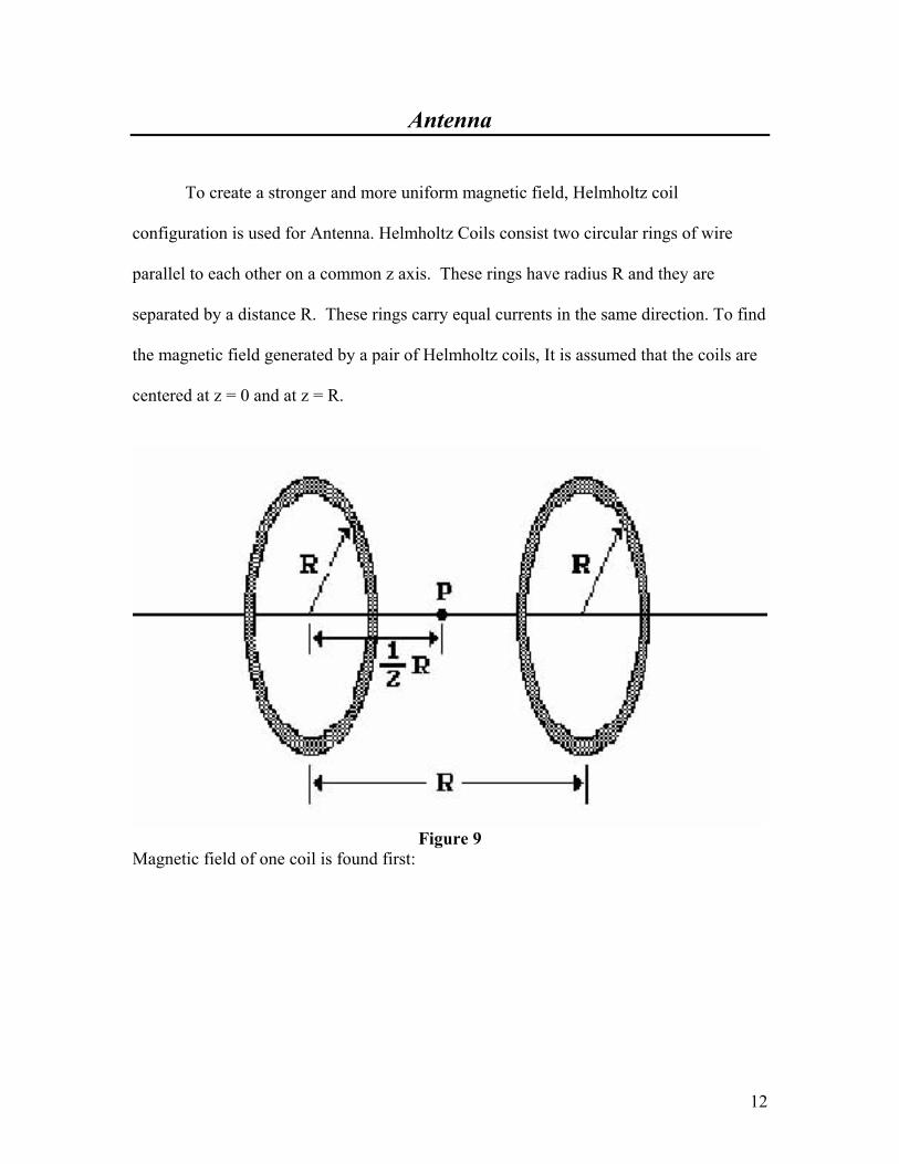
To create a stronger and more uniform magnetic field, Helmholtz coil
configuration is used for Antenna. Helmholtz Coils consist two circular rings of wire
parallel to each other on a common z axis. These rings have radius R and they are
separated by a distance R. These rings carry equal currents in the same direction. To find
the magnetic field generated by a pair of Helmholtz coils, It is assumed that the coils are
centered at z = 0 and at z = R.
Figure 9
Magnetic field of one coil is found first:
12
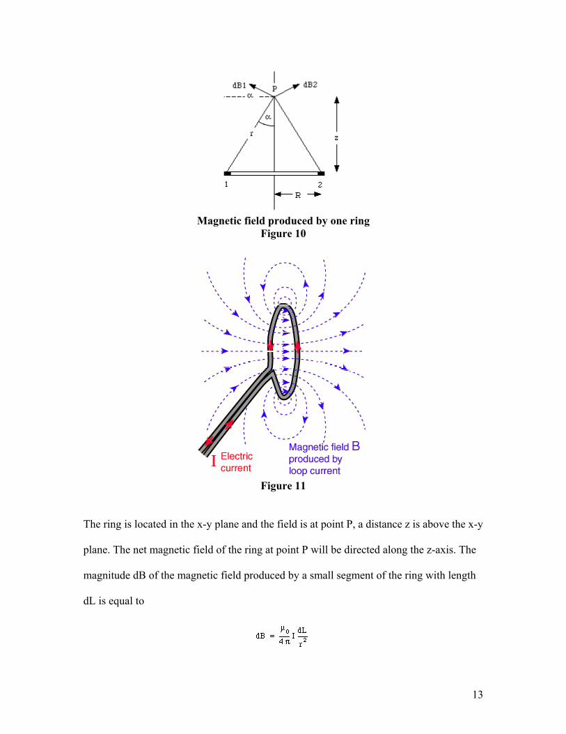
Magnetic field produced by one ring
Figure 10
Figure 11
The ring is located in the x-y plane and the field is at point P, a distance z is above the x-y
plane. The net magnetic field of the ring at point P will be directed along the z-axis. The
magnitude dB of the magnetic field produced by a small segment of the ring with length
dL is equal to
13
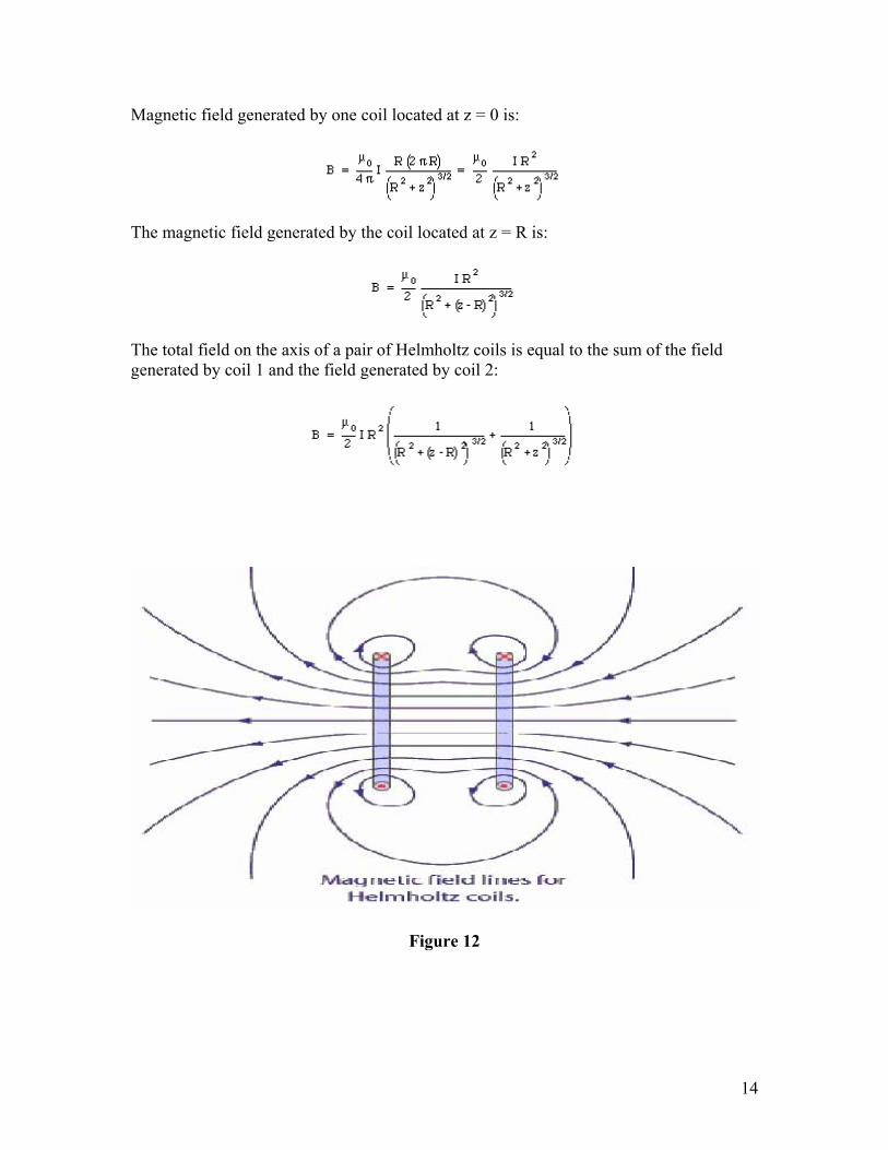
Magnetic field generated by one coil located at z = 0 is:
The magnetic field generated by the coil located at z = R is:
The total field on the axis of a pair of Helmholtz coils is equal to the sum of the field generated by coil 1 and the field generated by coil 2:
Figure 12
14

Conclusion
This project has taught us a lot about RF technology and offered us the opportunity to
explore and design RF circuits.
Despite the problems encountered with the preliminary design approaches, the RF power
system was successfully completed using an extremely challenging design approach.
Completion of this project is a low powered, low frequency, less expensive system that is
capable of detecting RF tag from a greater distance. It required us to involve in a broad
research on the topic of RF. Estimated cost of this project was approximately $172;
however, the actual cost of this project is $457.
The oscillator circuit when connected to the amplifier reliably produces a gain of
14.68dB. The Range of frequency transmitted by the amplifier varies 13.4-13.7 MHz.
The amplified signal could not be stabilized at 13.56 MHz. This results in the antenna
not being able to transmit consistent RF power at 13.56MHz, which is required by the tag
to be activated.
15

References
1. “History of RFID” May 12, 2004 http://www.rfidsurvival.com/HistoryofRFID.html
2. Microelectronics Circuits, by Sedra/Smith, 4th Edition, 1998 Oxford
University Press
3. “Physics 122 Lecture Notes” http://www.teacher.nsrl.rochester.edu/phy122/lecturenotes/chapter30/html
16