13745: liberty and freedom lc lightbars
TRANSCRIPT

Page 1
©2003 Whelen Engineering Company Inc.Form No.13745V (020616)
Au
tom
oti
ve:
Lig
htb
ars
For warranty information regarding this product, visit www.whelen.com/warranty
• Proper installation of this product requires the installer to have a good understanding of automotive electronics, systems and procedures.• Whelen Engineering requires the use of waterproof butt splices and/or connectors if that connector could be exposed to moisture.• Any holes, either created or utilized by this product, should be made both air- and watertight using a sealant recommended by your vehicle
manufacturer.• Failure to use specified installation parts and/or hardware will void the product warranty.• If mounting this product requires drilling holes, the installer MUST be sure that no vehicle components or other vital parts could be damaged
by the drilling process. Check both sides of the mounting surface before drilling begins. Also de-burr the holes and remove any metal shards or remnants. Install grommets into all wire passage holes.
• If this manual states that this product may be mounted with suction cups, magnets, tape or Velcro®, clean the mounting surface with a 50/50 mix of isopropyl alcohol and water and dry thoroughly.
• Do not install this product or route any wires in the deployment area of your air bag. Equipment mounted or located in the air bag deployment area will damage or reduce the effectiveness of the air bag, or become a projectile that could cause serious personal injury or death. Refer to your vehicle owner’s manual for the air bag deployment area. The User/Installer assumes full responsibility to determine proper mounting location, based on providing ultimate safety to all passengers inside the vehicle.
• For this product to operate at optimum efficiency, a good electrical connection to chassis ground must be made. The recommended procedure requires the product ground wire to be connected directly to the NEGATIVE (-) battery post (this does not include products that use cigar power cords).
• If this product uses a remote device for activation or control, make sure that this device is located in an area that allows both the vehicle and the device to be operated safely in any driving condition.
• Do not attempt to activate or control this device in a hazardous driving situation.• This product contains either strobe light(s), halogen light(s), high-intensity LEDs or a combination of these lights. Do not stare directly into
these lights. Momentary blindness and/or eye damage could result.• Use only soap and water to clean the outer lens. Use of other chemicals could result in premature lens cracking (crazing) and discoloration.
Lenses in this condition have significantly reduced effectiveness and should be replaced immediately. Inspect and operate this product regularly to confirm its proper operation and mounting condition. Do not use a pressure washer to clean this product.
• It is recommended that these instructions be stored in a safe place and referred to when performing maintenance and/or reinstallation of this product.
• FAILURE TO FOLLOW THESE SAFETY PRECAUTIONS AND INSTRUCTIONS COULD RESULT IN DAMAGE TO THE PRODUCT OR VEHICLE AND/OR SERIOUS INJURY TO YOU AND YOUR PASSENGERS!
Warnings to InstallersWhelen’s emergency vehicle warning devices must be properly mounted and wired in order to be effective and safe. Read and follow all of Whelen’s writteninstructions when installing or using this device. Emergency vehicles are often operated under high speed stressful conditions which must be accounted forwhen installing all emergency warning devices. Controls should be placed within convenient reach of the operator so that they can operate the system withouttaking their eyes off the roadway. Emergency warning devices can require high electrical voltages and/or currents. Properly protect and use caution aroundlive electrical connections.Grounding or shorting of electrical connections can cause high current arcing, which can cause personal injury and/or vehicledamage, including fire. Many electronic devices used in emergency vehicles can create or be affected by electromagnetic interference. Therefore, afterinstallation of any electronic device it is necessary to test all electronic equipment simultaneously to insure that they operate free of interference from othercomponents within the vehicle. Never power emergency warning equipment from the same circuit or share the same grounding circuit with radiocommunication equipment. All devices should be mounted in accordance with the manufacturer’s instructions and securely fastened to vehicle elements ofsufficient strength to withstand the forces applied to the device. Driver and/or passenger air bags (SRS) will affect the way equipment should be mounted. Thisdevice should be mounted by permanent installation and within the zones specified by the vehicle manufacturer, if any. Any device mounted in the deploymentarea of an air bag will damage or reduce the effectiveness of the air bag and may damage or dislodge the device. Installer must be sure that this device, itsmounting hardware and electrical supply wiring does not interfere with the air bag or the SRS wiring or sensors. Mounting the unit inside the vehicle by amethod other than permanent installation is not recommended as unit may become dislodged during swerving; sudden braking or collision. Failure to followinstructions can result in personal injury. Whelen assumes no liability for any loss resulting from the use of this warning device. PROPER INSTALLATIONCOMBINED WITH OPERATOR TRAINING IN THE PROPER USE OF EMERGENCY WARNING DEVICES IS ESSENTIAL TO INSURE THE SAFETY OFEMERGENCY PERSONNEL AND THE PUBLIC.
Warnings to UsersWhelen’s emergency vehicle warning devices are intended to alert other operators and pedestrians to the presence and operation of emergency vehicles andpersonnel. However, the use of this or any other Whelen emergency warning device does not guarantee that you will have the right-of-way or that otherdrivers and pedestrians will properly heed an emergency warning signal. Never assume you have the right-of-way. It is your responsibility to proceed safelybefore entering an intersection, driving against traffic, responding at a high rate of speed, or walking on or around traffic lanes. Emergency vehicle warningdevices should be tested on a daily basis to ensure that they operate properly. When in actual use, the operator must ensure that both visual and audiblewarnings are not blocked by vehicle components (i.e.: open trunks or compartment doors), people, vehicles, or other obstructions. It is the user’s responsibilityto understand and obey all laws regarding emergency warning devices. The user should be familiar with all applicable laws and regulations prior to the use ofany emergency vehicle warning device. Whelen’s audible warning devices are designed to project sound in a forward direction away from the vehicleoccupants. However, because sustained periodic exposure to loud sounds can cause hearing loss, all audible warning devices should be installed andoperated in accordance with the standards established by the National Fire Protection Association.
Safety FirstThis document provides all the necessary information to allow your Whelen product to be properly and safely installed. Before beginning the installation and/oroperation of your new product, the installation technician and operator must read this manual completely. Important information is contained herein that couldprevent serious injury or damage.
WARNING: This product can expose you to chemicals including Methylene Chloride which is known to the State of California to cause cancer, andBisphenol A, which is known to the State of California to cause birth defects or other reproductive harm. For more information go towww.P65Warnings.ca.gov.
Installation Guide:Liberty™ and Freedom™ LC Lightbars
51 Winthrop RoadChester, Connecticut 06412-0684Phone: (860) 526-9504Internet: www.whelen.comSales e-mail: [email protected] Service e-mail: [email protected]
®
ENGINEERING COMPANY INC.

Page 2
Insert foot into extrusion with locking plateattached.
Twist mounting foot intoposition
ANCHORPLATE
Loosely secure foot and locking plate.
Strap Mounting:1. Locate the mounting foot, anchor plate and locking plate included with your
lightbar. If not already present, install the locking plate onto the mountingfoot. When properly positioned, this plate is centered from side-to-side onthe mounting foot.
2. Flip the lightbar upside-down to expose the bottom of the extrusion andplace the mounting foot onto the extrusion.
3. Rotate the mounting foot 90° in a counter-clockwise direction. Make surethat the edges of the mounting foot swing into position under the extrusionmounting lip. Install an anchor plate onto the extrusion in the samemanner.
4. Repeat this procedure for the remaining mounting foot and anchor plateand return the lightbar to its right side-up position.
5. Position the lightbar onto the vehicle roof in the desired mounting location.One often selected location is directly above the B-pillars. This area is thestrongest part of the roof. Refer to your lightbar manual for cable exitlocation, to be sure that the lightbar is facing the proper direction.
6. Adjust the two mounting feet outwards so that they are as close to theedge of the roof as possible. Both mounting feet must be in full contact withthe roof. Be sure that there is no less than 1/2” clearance between roof and
lightbar at their closest point. When the mounting feet are in their properposition, lightly tighten the locking plate allen head set screws.
7. Return the lightbar to an upside-down position. Slide each anchor plateoutwards until it is fully engaged with its corresponding mounting foot. Withthe mounting feet and anchor plates in their proper positions tighten all ofthe set screws (2 or 4 per side) to 14-16 In. Lbs. Flip the lightbar right side-up and return it to its mounting position.
8. Open both drivers side doors. In the area directly below the mounting foot,pull the weather-strip away from the vehicle so the area where themounting strap will be secured is exposed. Repeat for the other side.
9. Insert the mounting strap through the mounting foot. Be sure that the strapfits flush against the area where it will be secured onto the vehicle. Insertthe tension bolt through the mounting strap and anchor plate, into thetinnerman nut. Tighten slightly with a long-shafted, Phillips screwdriver.Repeat procedure for passenger side.
10. If your mounting strap has mounting holes in the end of the strap, usethese holes as a template to drill appropriately sized pilot holes through thestrap and into the vehicle. Repeat for passenger side of the vehicle.
11. Firmly tighten the tension bolts to secure lightbar to vehicle.
IMPORTANT! The lightbar should be a minimum of 16" from any radio antennas!Permanent Mounting:1. Locate the mounting foot, anchor plate and locking plate included with your
lightbar. If not already present, install the locking plate onto the mountingfoot. When properly positioned, this plate is centered from side-to-side onthe mounting foot.
2. Flip the lightbar upside-down to expose the bottom of the extrusion andplace the mounting foot onto the extrusion.
3. Rotate the mounting foot 90° counter-clockwise. Make sure that the edgesof the mounting foot swing into position under the extrusion mounting lip.Install an anchor plate onto the extrusion in the same manner.
4. Repeat this procedure for the remaining mounting foot and anchor plateand return the lightbar to its right side-up position.
5. Position the lightbar onto the vehicle roof in the desired mounting location.One often selected location is directly above the B-pillars. This area is thestrongest part of the roof. Refer to your lightbar manual for cable exitlocation, to be sure that the lightbar is facing the proper direction.
6. Adjust the two mounting feet outwards so that they are as close to theedge of the roof as possible. Both mounting feet must be in full contact withthe roof. Be sure that there is no less than 1/2” clearance between roof andlightbar at their closest point. When the mounting feet are in their properposition, lightly tighten the locking plate allen head set screws.
7. Return the lightbar to an upside-down position. Slide each anchor plateoutwards until it is fully engaged with its corresponding mounting foot. Withthe mounting feet and anchor plates in their proper positions tighten all ofthe set screws (2 or 4 per side) to 14-16 In. Lbs. Flip the lightbar right side-up and return it to its mounting position.
8. Open both drivers side doors. In the area directly below the mounting foot,pull the weather-strip away from the vehicle so the area where themounting strap will be secured is exposed. Repeat for the other side.
9. Insert the mounting strap through the mounting foot. Be sure that the strapfits flush against the area where it will be secured onto the vehicle. Insertthe tension bolt through the mounting strap and anchor plate, into the
tinnerman nut. Tighten slightly with a long-shafted, Phillips screwdriver.Repeat procedure for passenger side.
10. If your mounting strap has mounting holes in the end of the strap, usethese holes as a template to drill appropriately sized pilot holes through thestrap and into the vehicle. Repeat for passenger side of the vehicle.
MountingPad
MountingPad
AdjustableMountingFoot
Washer
Nut
Bolt LockingPlate
MountingFootBase
StandardMountingFoot
WasherNut
Torque Set Screwsto 14-16 In. Lbs. !

Page 3
Adjustable Mounting Foot / Model MKAJ Standard Mounting Foot / Model MKEZFor Reference Only
Tighten screws
with torque wrench
set at 35 to 40 in/lbs
ModelMKAJ
On this model you may loosen the screws on the rear of the foot and adjust theangle of the lightbar. This is used if the angle of the roof is not level with the road.IMPORTANT: To adjust the leveling screws you must use a torque wrenchset at 35 to 40 ft. lbs
LockingPlate
Nut
MountingPad
Adjustmentscrews
LockWasher
AnchorPlate
TinnermanNut
MountingStrap
MountingScrew
TensionBolt
MountingFoot
Torque Set Screwsto 14-16 In. Lbs. !
MountingFoot
TinnermanNut
AnchorPlateLocking
Plate
MountingStrap
Mounting Screw
TensionBolt
Torque Set Screwsto 14-16 In. Lbs. !
NOTE: Unless otherwise specified, thelightbar mounting feet must be sitting asclose to the edge of the roof as possible.Mounting feet must also be in full contactwith the roof and not be hanging offthe edge.
IMPORTANT: For strap mounted bars, be sure you have the rightsized lightbar for your vehicle. The lightbar should be about thesame width as the vehicle roof. If thelightbar is too large or small it will notmount properly to the vehicle andmay shift or come loose during driving. 1/2" Minimum Clearance at Closest Point
MOUNTING FOOT
TINNERMANNUT
FOOTANCHOR
PLATE
SETSCREW
Plate slides intolightbar extrusion
5" Mounting Foot
NUTBOLT
SPLIT LOCKWASHER
METAL SCREW
NOTE: The mounting straps are made to fit the contours of individualvehicles. The strap
may look different. If your lightbar has a 5"mounting foot, it will assemble differently than the standardmounting foot. It also uses an extension to compensate forthe extra height. Follow these illustrations for assembly.Mounting to the lightbar is the same.
shown here is for example only. The strapfor your vehicle
NOTE:NOTE:NOTE:NOTE:NOTE:NOTE:
STRAP
S H E E TM E T A LSCREWS
EXTENSION
VEHICLE ROOFTorque Set Screwsto 14-16 In. Lbs.!
Routing your Lightbar Cable(s)1. To protect the headliner from damage caused by drilling the cable access
hole through the vehicle roof, allow a 5” to 7” distance between roof andheadliner by lowering the headliner before drilling.
WARNING! There may be a roof support member that spans thedistance between the driver’s and passenger’s side. DO NOT DRILLTHROUGH THIS MEMBER! Adjust the location until the hole can bedrilled without contacting this support member.
2. Using a 1” hole saw, drill the cable access hole. Use a round file to smoothand de-burr the edges than insert a 1” grommet.
3. Insert the cable(s) through the cable access hole into the vehicle. UseRTV silicone to weatherproof the access hole after the cable(s) are pulledcompletely into the vehicle.
4. Route the cable(s) through the vehicle following manufacturersrecommendations.
WARNING: Many vehicles are now equipped with side curtain and B-pillar air bags. Alternate routing may be required.
DRILLING THE CABLE ACCESS HOLE
Drill cable access hole in appropriate areafor your lightbar (see note)
FRONT OF LIGHTBAR
Forcables exiting
the Driver-sideof the extrusion
lightbarswith
Forcables exiting
the Passenger-sideof the extrusion
lightbarswith

2. CometFlash® 753. DoubleFlash 1504. DoubleFlash 755. SingleFlash 3756. SingleFlash 1507. SingleFlash 758. ActionFlash™ 1509. ModuFlash™10. ActionScan™
Front Outboard, Inboard and Center1. SignalAlert™ 752. CometFlash® 753. DoubleFlash 1504. DoubleFlash 75
8. ActionFlash™ 1509. ModuFlash™10. Steady/SF7511. Steady/Steady12. ActionScan™Take-Down / Alley1. T-D & Alley - SingleFlash 240 ALT2. T-D & Alley - DoubleFlash 120 ALT3. T-D only - SingleFlash 240 SIM4. T-D only - DoubleFlash 120 SIMTraffic Advisor™ Sequence1. Seq to Solid2. Seq On - Seq Off3. One Lamp Triple4. Two Lamp Triple
Connecting the Cables:WARNING! All Customer supplied wires that connect to the positiveterminal of the battery must be sized to supply at least 125% of themaximum operating current and FUSED at the battery to carry thatload. DO NOT USE CIRCUIT BREAKERS WITH THIS PRODUCT!
Power Cable:1. Open the wiring shield lid and route the power cable into the wiring shield
and towards the firewall. Make sure you do not to pinch or crush anywires when running them through the wire shield.
2. Follow the factory wiring harness through the firewall. It may benecessary to drill a hole in the firewall. If so, be absolutely sure that thereare no components that could be damaged by drilling. After the hole hasbeen drilled, insert a grommet to protect the cable.
3. Route the cable along the factory wiring harness to the battery.
4. Install a 30 amp fuse block (customer supplied) on the end of the REDwire in the power cable. Remove the fuse from the fuse block beforeconnecting any wires to the battery.
5. Connect the fuse block to the POSITIVE (+) terminal on the battery. Therecan not be more than two feet of wire between the fuse block and thebattery. The wire between the fuse block and the battery is “unprotected”,do not allow this wire to touch any other wires.
6. Connect the BLACK wire to the factory chassis ground.
Cruise Lights & AUX (WHITE/ORANGE):The WHITE/ORANGE wire operates in one of 3 different modes. Selecting amode is controlled with the Scan-Lock™ wire. Using Scan-Lock™ (See Scan-Lock™), change between the 3 available modes as though you were changingflash patterns. The three modes are as follows:
MODE 1 (Default) - Cruise Lights in High Power and the AUX port is activated.
MODE 2 - Cruise Lights in Low Power and the AUX port is activated.
MODE 3 - Cruise Lights are not activated and the AUX port is activated.
Hi/Low Power (VIOLET):The type of switch used is dependant on how the operator wishes the Hi/Lowfeature to function:
Latching Mode: By applying +12 VDC voltage to the VIOLET wire for less than1 second, the lightbar is “latched” into low power operation. The unit must beturned off and then back on to restore normal, high power operation (amomentary switch is preferred).
Pag
Wire Color Function FuseGREEN . . . . . .Front Corner LEDs . . . . . . 1 AMPBLUE . . . . . . .Rear Corner LEDs . . . . . . 1 AMPGRN/WHT . . . .Front Outboard LEDs . . . . 1 AMPBLU/WHT . . . .Rear Outboard LEDs . . . . 1 AMPGRN/BLK . . . .Front Inboard LEDs . . . . . 1 AMPBLU/BLK . . . .Rear Inboard LEDs . . . . . 1 AMP
WHT/GRN. . . Right TA . WHT/BLU . . . Flashing AYELLOW . . . Pass.-SideWHITE . . . . . Driver-SideWHT/BLK . . . Take-DownWHT/ORG . . Cruise LighWHT/YEL . . . . . Left TA
Control Cable: Extend the control cable to your switch panel and maketo your control head or switch box and is fused there. Applying +12VDC to a
Special Order Lightbars:
Unicor Lightbar:
Wire Color Function FuseGREEN . . . .All Front LEDs . . . . . . . . . . . . 1 AMPBLUE . . . . .Rear LEDs / RED-BLUE . . . . 1 AMPVIOLET . . . .Flashing Ctr RED & Alleys . . . 1 AMPORANGE . .Take Downs . . . . . . . . . . . . . . 1 AMPGREY . . . . .Rear AMBER . . . . . . . . . . . . . 1 AMPYELLOW. . .Passenger Alley . . . . . . . . . . . 1 AMPWHITE . . . .Driver Alley. . . . . . . . . . . . . . . 1 AMPWHT/BLK . .Steady Center RED . . . . . . . . 1 AMP
Philadelphia Lightba
BLU/BLK . . . End ExternWHT/RED. . . Front ExterWHT/BRN . . Rear ExterYELLOW . . . PassengerWHITE . . . . . Driver SideGREEN. . . . . Front CornBLUE . . . . . . Rear CorneGRN/WHT . . Front OutbBLU/WHT . . . Rear OutboGRN/BLK . . . Front OutbWHT/BLU . . . Flashing A
Level Mode: Applying +12 VDC voltage to the VIOLET wire for more than 1second holds the lightbar in low power mode until voltage is removed (a toggleswitch is preferred).
IMPORTANT NOTE: The corner modules in your lightbar do notswitch to low power when this option is applied. They will alwaysremain in normal high power.
Scan-Lock™ (WHITE/VIOLET):TO CYCLE FORWARD THROUGH AVAILABLE PATTERNS: Activate ONLYthe control wire of the function you wish to effect and apply +12 volts to theScan-Lock™ wire (WHITE/VIOLET) for less than 1 second and release. Thiswill change the pattern. For example, to change the Front Outboard LEDpattern, apply +12VDC to the GREEN/WHITE wire and then momentarily apply+12VDC to the WHITE/VIOLET wire. Repeat until the desired pattern isdisplayed. Let this pattern run for 5 seconds to configure it as the pattern theFront Outboard LEDs will display when activated. Important: Only ONEfunction may be active while changing patterns. Repeat for next pattern.
TO CHOOSE A PATTERN: Allowing the desired pattern to run for more than 5seconds makes it the default pattern.
TO RESET TO THE FACTORY DEFAULT PATTERN: Turn off all lightbarfunctions. Apply +12 volts to the Scan-lock™ wire and turn the appropriatefunction back on and it is now restored to its factory default pattern.
Front Corner, Rear Corner, OutboardInboard and Center1. SignalAlert™ 75
5. SingleFlash 3756. SingleFlash 1507. SingleFlash 75
Available Flash Patterns:
e 4
. . . . . . . . . . . . . 1 AMPlley & T.D.’s . . . 1 AMP Alley Lights . . . 1 AMP Alley Lights. . . 1 AMP Lights . . . . . . . 1 AMPts & AUX . . . . . 1 AMP. . . . . . . . . . . . . 1 AMP
WHT/BRN . . . . .Rear Center LEDs . . . 1 AMPVIOLET . . . . . . .Hi/Low Power . . . . 0.5 AMPSWHT-VIO . . . . . .Scan-Lock™. . . . . . 0.5 AMPSWHT/RED. . . . . .Front Center LEDs . . . 1 AMPNONE . . . . . . . . .RFI shield drain / to groundActivating WHT/GRN + WHT/YEL = Split TA
your connections using the information provided. The control cable connectscontrol wire activates its function. Fuse as noted below.
r:
al Pods . . . . . . . 1 AMPnal Pods . . . . . . 1 AMPnal Pods. . . . . . . 1 AMP Alleys . . . . . . . . 1 AMP Alleys . . . . . . . . 1 AMPers . . . . . . . . . . . 1 AMPrs . . . . . . . . . . . 1 AMP
oards . . . . . . . . . 1 AMPards . . . . . . . . . 1 AMP
oards . . . . . . . . . 1 AMPlley & TDs. . . . . . 1 AMP
WHT/BLK . . TakeDowns. . . . . . . . . . . . . 1 AMPWHT/ORG . . . . Cruise Lts. & AUX . . . . . . 1 AMPVIOLET . . . . . . Hi-Low Power . . . . . . . . 0.5 AMPWHT/VIO . . . . . Scan-Lock™ . . . . . . . . . 0.5 AMPWHT/GRN . . . . Right TA. . . . . . . . . . . . . . 1 AMPWHT/YEL . . . . . Left TA . . . . . . . . . . . . . . . 1 AMPActivating WHT/GRN + WHT/YEL = Split TA
Leader Lightbar:
GREEN . . . . . . Front Corner LEDs. . . . . . 1 AMPGRN/WHT . . . . Front Outboards. . . . . . . . 1 AMPGRN/BLK. . . . . Front Inboards . . . . . . . . . 1 AMPWHT/RED . . . . Front Center LEDs. . . . . . 1 AMP

Page 5
Lighthead mounting holessnap into the raised bosseson the lighthead bracket.
Ears on lighthead bracketslide into channels inextrusion (base).
Snap lightheadinto bracket.
En
dc
ap
&G
as
ke
t50
0 S
erie
sA
lley
Lig
ht
Mounting Lightheads to Extrusion
If lightbar hasno alley light,use nuts tohold lens in.
Halogen Lightheadslides into extrusion here.
BASE
EXTRUSION
LR
-11
Take
-do
wn
an
dA
lley
Lig
ht
LR
-11
Alle
y L
igh
t
Endcap
LensScrew
BASE EXTRUSION SIDE VIEW
LIGHTHEAD
En
dca
p, G
aske
t , L
ense
s &
Sp
acer
s In
stal
lati
on
Gas
ket
& H
alo
gen
Alle
y L
igh
t
BARB
BOSS Align lightheadreflector up with 4bosses in endcap.Press reflector intoplace.
En
dc
ap
wit
hin
teg
rate
dg
as
ke
t
Serv ic ing : L ibe r ty L igh tbarServ ic ing : F reedom™ Ligh tbar
Halogen Alley Light
Remove the screws (A) that hold the endcap on and pull the endcap and gasket (C) off.4 (B) Slide lenses(D) out of the lightbar, to gain access to the extrusion. When reinstalling the lenses and spacers, install thecord seal (NFPA / See below). When reinstalling the endcap, place the endcap gasket into it's position onthe endcap and line up all the tabs and holes. Spacers (not shown) mount the same as lenses.
D
D
C
Insert
cord s
eal into
track in
lens
A
Seal Cord Installation / NFPA Only:
Cut the seal cord approx. 1-1/2" longer than the extrusion on each side.
Rub silicone over the cord seal leaving 3 to 4 inches on one end dry.
Begining with 1 corner lens, start the lens into the bottom
lens track. Place the cord seal onto the groove in the
top of the lens eav 1 to 2 inches
Hold onto the left end of the seal hanging
out and slide the corner lens into
position.
1 -
2 -
3 -
4 -
3 -
3 -
4 -
4 -
. L e free.
Inspect seal cord for any areas that have wrinkled.
Especially in the areas around the dividers.
Push the lenses together tight and trim excess seal
cord at each end.
6 -
7 -
6 -
7 -
From the opposite end of the
lightbar, pull the seal
cord tight and install
the remaining lenses
and divider.
5 -
5 -
5 -
5 -
5 -
NOTE: Lens dividers mustbe installed as each lens isput into position
Installing Corner Linear-LED®
Insert the tabs on the lighthead housing, into the channels in the extrusion.
Installing Lens and Lighthead
Lensfits
here
Extrusion secures to Support Bracket.
SUPPORTBRACKET
B
BASE EXTRUSION
SUPPORTBRACKET
SECURE TOEXTRUSIONTO SECUREBRACKET
EXTRUSION
LR
11 T
AK
ED
OW
N
LR11ALLEYLIGHT
BASE
EXTRUSION
LR
-11
Take
-do
wn
ADJUSTA
NG
LE
Secure lightheadbracket to extrusion
Snap lightheadbracket into TD
bracket
Slide intotracks inextrusion
Halogen Lightheadsnaps into extrusion
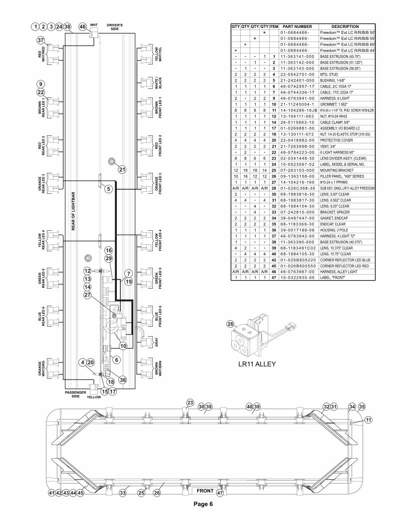
Page 6
BR
OW
NR
EA
R L
ED
1
BR
OW
NF
RO
NT
LE
D 1
BR
OW
NW
HT
/BR
NG
RA
Y
OR
AN
GE
WH
T/O
RG
GR
EE
NF
RO
NT
LE
D 5
YE
LL
OW
FR
ON
T L
ED
4O
RA
NG
EF
RO
NT
LE
D 3
RE
DF
RO
NT
LE
D 2
RE
AR
OF
LIG
HT
BA
R
BL
UE
RE
AR
LE
D 6
GR
EE
NR
EA
R L
ED
5Y
EL
LO
WR
EA
R L
ED
4O
RA
NG
ER
EA
R L
ED
3R
ED
RE
AR
LE
D 2
DRIVER'SSIDE
PASSENGERSIDE
YE
LL
OW
WH
T/Y
EL
WH
ITE
/B
LA
CK
WHT
RE
DW
HT
/RE
D
YELLOW
461 2 3 24 38
37
9
21
22
5
29
7
14
27
10
6
3618
17
16
204
BL
UE
FR
ON
T L
ED
6
FRONT
11
3534313239403930
45 334442 254341 26 47
1319
15
23
12
LR11 ALLEY
28
4 6 - 0 7 4 4 3 3 6 - 1 7
4 6 - 0 7 4 2 9 5 7 - 1 7
2 1 - 2 4 2 4 0 1 - 0 0 0
2 2 - 0 5 4 2 7 0 1 - 0 0
11 - 3 6 3 1 4 3 - 0 0 0
11 - 3 6 3 1 4 2 - 0 0 0
11 - 3 6 3 1 4 1 - 0 0 0
HARNESS, ALLEY LIGHT
ENDCAP, CLEAR
GASKET, ENDCAP
HOUSING, 2 POLE
BASE EXTRUSION (40.375")
LENS, 10.375" CLEAR
LENS, 15.75" CLEAR
HARNESS, 4 LIGHT 72"
CORNER REFLECTOR LED RED
CORNER REFLECTOR LED BLUE
LABEL, "FRONT"
ITEM PART NUMBER DESCRIPTIONQTY QTY QTY QTY
Freedom™ Ext LC R/R/B/B 44"
Freedom™ Ext LC R/R/B/B 50"
Freedom™ Ext LC R/R/B/B 55"
Freedom™ Ext LC R/R/B/B 60"
0 1 - 0 6 8 4 4 6 6 -
0 1 - 0 6 8 4 4 6 6 -
0 1 - 0 6 8 4 4 6 6 -
0 1 - 0 6 8 4 4 6 6 -
1
3
2
4
6
5
7
14
11
9
10
12
17
18
20
46
27
24
22
21
23
25
26
30
28
31
33
32
35
34
36
38
37
39
40
42
45
47
0 1 - 0 2 6 9 8 8 1 - 0 0
2 2 - 0 4 1 6 9 8 2 - 0 0
1 3 - 1 3 0 111 - 0 7 2
2 6 - 0 11 5 6 6 3 - 1 0
1 3 - 1 0 4 111 - 0 6 3
1 4 - 1 0 4 2 8 6 - 1 6 J B
2 1 - 11 2 4 5 0 0 4 - 1
1
1
2
2
1
1
2
1
2
2
1
1
1
2
1
2
1
2
1
1 1 1 1
1
8
1
8 8
1 1
1 1
8
1
1
1
2
4
1 1
2
4
2
4
1
2
4
NUT, 1/4-20 ELASTIC STOP (316 SS)
#10-24 x 1-1/4" TX. PHD. SCREW W/SHLDR
CABLE, 17/C 22GA 17'
CABLE, 2/C 10GA 17'
BUSHING, 1-5/8"
MTG. STUD
BASE EXTRUSION (56.50")
BASE EXTRUSION (51.125")
BASE EXTRUSION (45.75")
ASSEMBLY, I/O BOARD LC
PROTECTIVE COVER
CABLE CLAMP, 5/8"
NUT, #10-24 WHIZ
GROMMET, 1.562"
0 7 - 2 6 3 1 0 3 - 0 0 0
0 9 - 1 3 6 3 1 5 8 - 0 0
6 8 - 11 8 3 3 6 9 - 3 0
1 4 - 1 0 4 2 1 6 - 1 6 0
1 0 - 0 5 2 3 0 6 7 - 0 2
0 2 - 0 3 4 1 4 4 8 - 3 0
3 8 - 0 4 8 7 4 4 7 - 0 0
6 8 - 1 9 8 4 1 0 4 - 3 0
6 8 - 1 9 8 3 8 1 7 - 3 0
6 8 - 1 9 8 3 8 1 6 - 3 0
0 7 - 2 4 2 8 1 5 - 0 0 0
3 9 - 0 0 1 7 1 8 8 - 0 8
11 - 3 6 3 3 9 0 - 0 0 0
6 8 - 11 8 3 4 9 1 C 0 2
6 8 - 1 9 8 4 1 0 5 - 3 0
4 6 - 0 7 6 3 9 4 2 - 0 0
4 6 - 0 7 6 3 9 4 1 - 0 0
4 6 - 0 7 6 3 9 6 7 - 0 0
4 6 - 0 7 8 4 2 2 3 - 0 0
A/RA/RA/R A/R
1111
18
12
6
111
8
2
8
12
10
18
16
1
6
14
12
4
4
2
4 4 4
1
2
1
2
1
2
1
1
1
4
1
2
2
1
1
2
44
2
4
2
LENS, 9.25" CLEAR
LENS, 6.562" CLEAR
BRACKET, SPACER
MOUNTING BRACKET
FILLER PANEL, "400" SERIES
#10-24 x 1 PPHMS
LABEL, MODEL & SERIAL NO.
LENS DIVIDER ASS'Y. (CLEAR)
LENS, 5.00" CLEAR
6 LIGHT HARNESS 60"
HARNESS, 6 LIGHT
22 2 2
0 1 - 0 2 6 B 8 0 5 5 5 0
0 1 - 0 2 6 B 8 0 5 2 2 0
2222
22 2 2
SUB ASY, SNGL LR11 ALLEY FREEDOM0 1 - 0 2 6 C 3 6 8 - 3 0A/RA/R A/R A/R
VENT, 3/4"2 1 - 7 2 6 3 9 9 8 - 0 022 2 2
1 0 - 0 3 2 2 9 3 5 - 0 011 1 1
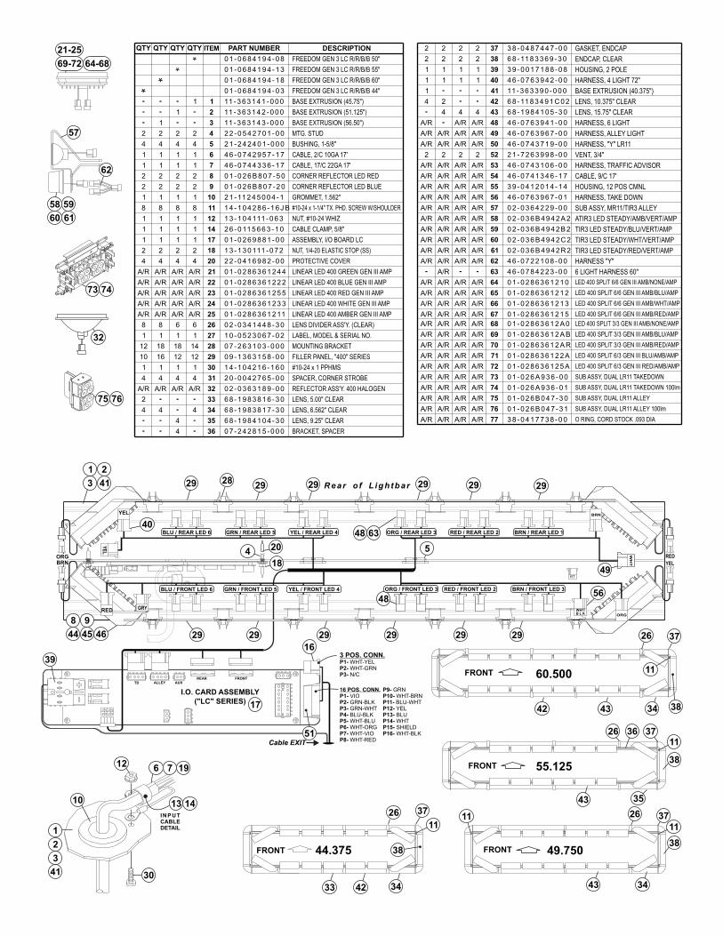
Page 7
I.O. CARD ASSEMBLY
("LC" SERIES)
TD ALLEY AUXREAR FRONT
3 POS. CONN.P1-P2-P3-
WHT-YELWHT-GRNN/C
Cable EXIT
16 POS. CONN.VIOGRN-BLKGRN-WHTBLU-BLKWHT-BLUWHT-ORGWHT-VIOWHT-RED
P1-P2-P3-P4-P5-P6-P7-P8-
P9- GRNP10-P11-P12-P13-P14-P15-P16-
WHT-BRNBLU-WHTYELBLUWHTSHIELDWHT-BLK
INPUTCABLEDETAIL
12
1
2
3
30
6
10
75
73
32
58 59
60 61
57
62
16
17
39
51
55.125
3726
43
11
38FRONT
35
60.500FRONT
26 37
38344342
49.750FRONT
3443
26 37
36
1111
38
11
FRONT 44.375
3442
26 37
38
33
48
BLU / REAR LED 6 GRN / REAR LED 5 YEL / REAR LED 4 ORG / REAR LED 3
YE
L
WH
T
40
BRNORG
YEL
RED
292929292929
40
29
18
4
29 29 29 29
5
8 9
44 45 46
41
1 2
3
RED
48
BRN
ORG
RT
YEL
49
RED / REAR LED 2 BRN / REAR LED 1
YEL / FRONT LED 4 ORG / FRONT LED 3 RED / FRONT LED 2 BRN / FRONT LED 356
BLU / FRONT LED 6 GRN / FRONT LED 5
GRY WHT/B L K
29
Rear o f L igh tbar
69-72 64-68
21-25
11
13 14
74
76
28
63
20
7 19
41
FREEDOM GEN 3 LC R/R/B/B 50"0 1 - 0 6 8 4 1 9 4 - 0 8
0 1 - 0 6 8 4 1 9 4 - 1 3 FREEDOM GEN 3 LC R/R/B/B 55"
0 1 - 0 6 8 4 1 9 4 - 1 8 FREEDOM GEN 3 LC R/R/B/B 60"
1 11 - 3 6 3 1 4 1 - 0 0 0 BASE EXTRUSION (45.75")
2 11 - 3 6 3 1 4 2 - 0 0 0 BASE EXTRUSION (51.125")
3 11 - 3 6 3 1 4 3 - 0 0 0 BASE EXTRUSION (56.50")
2 4 2 2 - 0 5 4 2 7 0 1 - 0 0 MTG. STUD
4 5 2 1 - 2 4 2 4 0 1 - 0 0 0 BUSHING, 1-5/8"
1 6 4 6 - 0 7 4 2 9 5 7 - 1 7 CABLE, 2/C 10GA 17'
1 7 4 6 - 0 7 4 4 3 3 6 - 1 7 CABLE, 17/C 22GA 17'
8
9
1 10 2 1 - 11 2 4 5 0 0 4 - 1 GROMMET, 1.562"
8 11 1 4 - 1 0 4 2 8 6 - 1 6 J B
1 12 1 3 - 1 0 4 111 - 0 6 3 NUT, #10-24 WHIZ
1 14 2 6 - 0 11 5 6 6 3 - 1 0 CABLE CLAMP, 5/8"
17
18 1 3 - 1 3 0 111 - 0 7 2
4 20 2 2 - 0 4 1 6 9 8 2 - 0 0 PROTECTIVE COVER
21
22
23
24
25
26
27
14 28 0 7 - 2 6 3 1 0 3 - 0 0 0 MOUNTING BRACKET
29 0 9 - 1 3 6 3 1 5 8 - 0 0 FILLER PANEL, "400" SERIES
30
31
32 0 2 - 0 3 6 3 1 8 9 - 0 0 REFLECTOR ASS'Y. 400 HALOGEN
33
34
35
36
18
4
1
1
8
1
1
1
4
22
4
1
1
1
8
1
1
2
4
18
2 2
A/R A/R A/R
16 12 12
111 1 4 - 1 0 4 2 1 6 - 1 6 0 #10-24 x 1 PPHMS
#10-24 x 1-1/4" TX. PHD. SCREW W/SHOULDER
NUT, 1/4-20 ELASTIC STOP (SS)
2 0 - 0 0 4 2 7 6 5 - 0 0 SPACER, CORNER STROBE444
1
1
1
CORNER REFLECTOR LED RED0 1 - 0 2 6 B 8 0 7 - 5 0222
CORNER REFLECTOR LED BLUE0 1 - 0 2 6 B 8 0 7 - 2 02 2 2
LINEAR LED 400 BLUE GEN III AMP0 1 - 0 2 8 6 3 6 1 2 2 2A/R A/R A/R
LINEAR LED 400 RED GEN III AMPA/R A/R A/R
LINEAR LED 400 WHITE GEN III AMPA/R A/R A/R
LINEAR LED 400 AMBER GEN III AMPA/RA/RA/R
68
1 1 1
6
1 0 - 0 5 2 3 0 6 7 - 0 2
0 2 - 0 3 4 1 4 4 8 - 3 0
LABEL, MODEL & SERIAL NO.
LENS DIVIDER ASS'Y. (CLEAR)
LENS, 9.25" CLEAR6 8 - 1 9 8 4 1 0 4 - 3 04
LENS, 6.562" CLEAR6 8 - 1 9 8 3 8 1 7 - 3 04 4
LENS, 5.00" CLEAR6 8 - 1 9 8 3 8 1 6 - 3 0
BRACKET, SPACER0 7 - 2 4 2 8 1 5 - 0 0 04
A/R
4
2
8
A/R
A/R
A/R
10
A/R
12
1
4
1
FREEDOM GEN 3 LC R/R/B/B 44"0 1 - 0 6 8 4 1 9 4 - 0 3
1
2
1
4
1
2
2
8
1
1
2
4
0 1 - 0 2 8 6 3 6 1 2 5 5
0 1 - 0 2 8 6 3 6 1 2 3 3
0 1 - 0 2 8 6 3 6 1 2 11
LINEAR LED 400 GREEN GEN III AMP0 1 - 0 2 8 6 3 6 1 2 4 4A/RA/RA/RA/R
ASSEMBLY, I/O BOARD LC0 1 - 0 2 6 9 8 8 1 - 0 011 1 1
ITEM PART NUMBER DESCRIPTIONQTY QTY QTY QTY 37
38 6 8 - 11 8 3 3 6 9 - 3 0 ENDCAP, CLEAR
GASKET, ENDCAP3 8 - 0 4 8 7 4 4 7 - 0 0222
222
HOUSING, 2 POLE3 9 - 0 0 1 7 1 8 8 - 0 839111
40
2
2
1
41
42
43
BASE EXTRUSION (40.375")11 - 3 6 3 3 9 0 - 0 0 01
LENS, 10.375" CLEAR6 8 - 11 8 3 4 9 1 C 0 2
LENS, 15.75" CLEAR6 8 - 1 9 8 4 1 0 5 - 3 0444
4 2
HARNESS, 4 LIGHT 72"4 6 - 0 7 6 3 9 4 2 - 0 011 1 1
HARNESS, 6 LIGHT4 6 - 0 7 6 3 9 4 1 - 0 0A/RA/R A/R 48
HARNESS, ALLEY LIGHT4 6 - 0 7 6 3 9 6 7 - 0 049A/RA/RA/RA/R
50
VENT, 3/4"22 2 2 52 2 1 - 7 2 6 3 9 9 8 - 0 0
HARNESS, TRAFFIC ADVISOR4 6 - 0 7 4 3 1 0 6 - 0 053A/RA/R A/R A/R
CABLE, 9/C 17'4 6 - 0 7 4 1 3 4 6 - 1 7A/RA/RA/R A/R 54
HOUSING, 12 POS CMNL3 9 - 0 4 1 2 0 1 4 - 1 4A/RA/R A/R A/R 55
HARNESS, TAKE DOWN4 6 - 0 7 6 3 9 6 7 - 0 156A/RA/RA/RA/R
4 6 - 0 7 2 2 1 0 8 - 0 0
0 2 - 0 3 6 4 2 2 9 - 0 0
0 2 - 0 3 6 B 4 9 4 2 R 2
0 2 - 0 3 6 B 4 9 4 2 C 2
0 2 - 0 3 6 B 4 9 4 2 B 2
0 2 - 0 3 6 B 4 9 4 2 A 2
A/RA/R A/R A/R 57
59
58
60
62
61
HARNESS "Y"
SUB ASSY, MR11/TIR3 ALLEY
TIR3 LED STEADY/RED/VERT/AMP
TIR3 LED STEADY/WHT/VERT/AMP
TIR3 LED STEADY/BLU/VERT/AMP
ATIR3 LED STEADY/AMB/VERT/AMPA/R A/R A/R A/R
A/R A/R A/R A/R
A/R A/R A/R A/R
A/R A/R A/R A/R
A/R A/R A/R A/R
A/R 63 4 6 - 0 7 8 4 2 2 3 - 0 0 6 LIGHT HARNESS 60"
LED 400 SPLIT 6/6 GEN III AMB/NONE/AMP0 1 - 0 2 8 6 3 6 1 2 1 0
67
66
65
64
A/RA/RA/RA/R
A/R
A/R
A/R
A/R
A/R
A/R
A/R
A/R
A/RA/RA/RA/R
A/R
A/R
A/R
A/R
A/R
A/R
A/R
A/R
A/R
A/RA/R
A/R A/R
A/R A/R
A/R
68
69
71
70
LED 400 SPLIT 6/6 GEN III AMB/BLU/AMP
LED 400 SPLIT 6/6 GEN III AMB/WHT/AMP
LED 400 SPLIT 6/6 GEN III AMB/RED/AMP
0 1 - 0 2 8 6 3 6 1 2 1 2
0 1 - 0 2 8 6 3 6 1 2 1 3
0 1 - 0 2 8 6 3 6 1 2 1 5
0 1 - 0 2 8 6 3 6 1 2 A B
0 1 - 0 2 8 6 3 6 1 2 A R
0 1 - 0 2 8 6 3 6 1 2 2 A
0 1 - 0 2 8 6 3 6 1 2 5 A
LED 400 SPLIT 3/3 GEN III AMB/BLU/AMP
LED 400 SPLIT 3/3 GEN III AMB/RED/AMP
LED 400 SPLIT 6/3 GEN III BLU/AMB/AMP
LED 400 SPLIT 6/3 GEN III RED/AMB/AMP72
A/R A/R A/R A/R 0 1 - 0 2 8 6 3 6 1 2 A 0 LED 400 SPLIT 3/3 GEN III AMB/NONE/AMP
73
74
75
76
A/R A/R A/R A/R
A/R A/R A/R A/R
A/R A/R A/R A/R
A/R A/R A/R A/R
0 1 - 0 2 6 A 9 3 6 - 0 0
0 1 - 0 2 6 A 9 3 6 - 0 1
0 1 - 0 2 6 B 0 4 7 - 3 0
0 1 - 0 2 6 B 0 4 7 - 3 1
4 6 - 0 7 4 3 7 1 9 - 0 0 HARNESS, "Y" LR11A/R A/R A/R A/R
SUB ASSY, DUAL LR11 TAKEDOWN
SUB ASSY, DUAL LR11 TAKEDOWN 100lm
SUB ASSY, DUAL LR11 ALLEY 100lm
SUB ASSY, DUAL LR11 ALLEY
A/RA/R A/R A/R 3 8 - 0 4 1 7 7 3 8 - 0 077 O RING, CORD STOCK .093 DIA
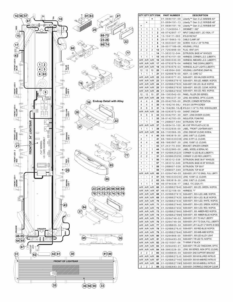
Page 8
DRIVER
PASSNGR
81 83
31 62 42 38 41
33
61
35
40
595836
FRONT OF LIGHTBARFRONT OF LIGHTBAR
BR
N
OR
G
BR
OW
NL
ED
1
RE
DL
ED
2O
RA
NG
EL
ED
3
FR
ON
T L
ED
1B
RO
WN
FR
ON
T L
ED
2
RE
DF
RO
NT
LE
D 3
OR
AN
GE
YE
LL
OW
LE
D 4
GR
EE
NL
ED
5
BL
UE
LE
D 6
FR
ON
T L
ED
4Y
EL
LO
WF
RO
NT
LE
D 5
GR
EE
NF
RO
NT
LE
D 6
BL
UE
YE
L
21
EN
DC
AP
LE
D
BR
NOR
AN
GE
15
YE
L
RE
D
FR
ON
T
I.O
. C
AR
DA
SS
EM
BLY
("LC
" S
ER
IES
) RE
AR
IAL
ITD
57
67
561418
37
84
23
70
24
71
25
72
26
73
66
74
68
78
69
79
20
43
67
43
17
FR
ON
T O
F 54" L
IGH
TB
AR
FR
ON
T O
F 54" L
IGH
TB
AR
RA
LT
D
YE
L
RE
D
RT
D
Endcap Detail with Alley
22
39
28
37
22
27
7466
20
23-26
68-73
64 65
48-55
LA
76
60
77
85 30
1
4
2
5
6 63
R E DWIRE
9
ITEM DESCRIPTIONQTY QTY QTY
Liberty™ Gen 3 LC R/R/B/B 48"
Liberty™ Gen 3 LC B/B/B/B 43"
Liberty™ Gen 3 LC R/R/B/B 54"
PART NUMBER
LENS, ENDCAP (CLEAR) W/SEAL
#6 X 5/8" PPH PLASTI-LOC SS
EXTRUSION, TOP 44"
INSULATOR, FOAM PAD
ASS'Y., LENS DIVIDER (CLEAR)
GASKET, ENDCAP
#10-24 X 1-1/4" TX. PHD. W/SHOULDER
LENS, 500 SERIES, OPTIC (CLEAR)
SUB-ASS'Y, 500 LED, BLUE W/2POS
SUB-ASS'Y., 500 LED, AMBER, W/2POS.
SUB-ASS'Y., 500 HALOGEN W/3POS.
HOUSING, LIGHTHEAD (SNAP-IN)
HARNESS, INBOARD L.E.D. (LIBERTY)
EXTRUSION, BASE 44" W/HOLES
PLUG, VENT (3/4")
CABLE CLAMP, 5/8"
#10-24 WIZ NUT
INPUT CABLE ASS'Y., (2C-10GA.) 17'
GROMMET, 1.562"
LABEL, MODEL & SERIAL NO.
SUB-ASS'Y., 500 LED, CLEAR, W/2POS.
LENS, 15.800" LG. (CLEAR)
1
BRACKET, SPACER CORNER
LENS, 5.687" LG. (CLEAR)
PANEL, FILLER (500 SERIES)
#10-24 X 3/8 PPH SCREW
LABEL, "FRONT" LIGHTBAR ASS'Y.
1
HARNESS, CORNER L.E.D. (LIBERTY)
HARNESS, TAKE DOWN (LIBERTY)
HARNESS, ALLEY LIGHTS (LIBERTY)
LENS, 8.375" LG. (CLEAR)
SUB-ASS'Y., 500 LED, RED, W/2POS.
ASS'Y., I.O. CARD "LC"
CORNER 12 LED RED (LIBERTY)
SPACER, CORNER RETENTION
EXTRUSION, BASE 38.61" W/HOLES
EXTRUSION, BASE 49.39" W/HOLES
EXTRUSION, TOP 38.61"
EXTRUSION, TOP 49.39"
44
1 1
1 1
1 1
1 1
1 1
2 2
1
1 1
A/RA/R
A/RA/R
A/RA/R
12 12
11
A/R A/R
A/R
A/RA/R
A/R
A/R
A/R
A/R
A/R
12 12
A/R A/R
4 4
8 8
A/R A/R
6 6
1 1
1
A/R A/R
1 1
A/R A/R
1
1
2 2
2 2
1 1
4
4 4
4
4
LENS, 5.062" LG. (CLEAR)
LENS, 10.500" LG. (CLEAR)
CABLE, 17/C 22GA (17')1 1
SUB-ASS'Y., 500 LED, GREEN, W/2POS.A/RA/R
CORNER 12 LED BLUE (LIBERTY)
A/R A/R SUB ASSY, LR11 T-D SINGL. FULL LBRTY
HARNESS, "Y"A/RA/R A/R
A/R A/R SUB-ASS'Y., 500 4 LED, AMB, W/2POS.
A/R A/R
SUB-ASS'Y., 500 4 LED, WHITE, W/2POS.A/RA/R
A/R A/R SUB-ASS'Y., 500 4 LED, GREEN, W/2POS.
SUB-ASS'Y., 500 4 LED, RED, W/2POS.A/R A/R
SUB-ASS'Y., 500 AMBER-RED W/2POS.A/R A/R
SUB-ASS'Y., 500 AMBER-BLUE W/2POS.A/RA/R
A/R A/R SUB ASSY, LR11 TD HALF LIBERTY
A/R A/R SUB ASSY, LR11 T-D DUAL FULL LIBERTY
A/R A/R
SUB-ASS'Y., 500 RED-BLUE W/2POS.A/R A/R
A/R A/R SUB-ASS'Y., 500 AMB-AMB W/2POS.
A/R
A/R
A/R
A/R
SUB-ASS'Y, TIR LED TD, N/OPTIC
SUB-ASS'Y., 500 LED ALLEY LIGHT
SUB-ASS'Y, 500 4 LED, BLUE W/2POS.
SUB ASSY, LR11 ALLEY LT WHITE 20 DEG
A/R A/R
SUB-ASS'Y, TIR LED TAKEDOWN, OPTIC
TY-WRAP, 6" BLACK
A/RA/R
A/R A/R LENS, 500 SERIES, NON OPTIC (CLEAR)
SUB ASSY, END SUPPORT BRACKET2 2
A/R A/R
A/R A/R
A/R A/R
SUB ASSY, 500 6/6 BLU/RED INTRLVD
SUB ASSY, 500 6/6 AMB/RED INTRLVD
SUB ASSY, 500 6/6 AMB/BLU INTRLVD
1
1
4
1
1
1
1
1
2
1
A/R
A/R
A/R
10
A/R
A/R
A/R
A/R
A/R
10
A/R
4
8
A/R
8
1
A/R
1
A/R
1
1
4
1
4
4
2
1
A/R
A/R
A/R
A/R
A/R
A/R
A/R
A/R
A/R
A/R
A/R
A/R
A/R
A/R
A/R
A/R
A/R
A/R
A/R
2
A/R
A/R
A/R
22 2
40
39
37
36
35
33
32
31
30
29
28
27
26
25
24
23
22
21
20
18
17
16
15
14
12
9
6
5
4
2
1
41
42
43
44
49
51
38
56
57
59
58
60
62
61
63
66
67
68
69
70
71
72
73
74
75
76
77
78
79
81
80
82
83
84
85
86
87
88
89
0 1 - 0 6 8 4 1 9 1 - 1 3
0 1 - 0 6 8 4 1 9 1 - 0 9
0 1 - 0 6 8 4 1 9 1 - 1 6
6 8 - 11 8 3 5 6 6 - 3 S
1 5 - 0 6 5 4 1 0 - 1 0 0
11 - 2 6 B 6 0 7 - 0 4 4
3 8 - 0 1 4 2 7 8 3 - 0 0
0 2 - 0 3 4 2 7 9 1 - 3 0
3 8 - 0 2 8 3 5 7 2 - 0 0
1 4 - 1 0 4 2 8 6 - 1 6 J B
6 8 - 1 9 6 3 2 3 7 - 3 0
0 1 - 0 2 6 B 8 2 7 6 5 0
0 1 - 0 2 6 B 8 2 7 6 2 0
0 1 - 0 2 6 B 8 2 7 6 1 0
0 2 - 0 3 8 3 5 7 7 - 0 3
11 - 4 8 3 5 6 4 - 0 0 0
4 6 - 0 9 6 3 3 3 0 - 0 0
11 - 3 6 3 3 1 2 - 0 4 4
2 1 - 7 2 6 3 9 9 8 - 0 0
3 9 - 0 0 1 7 1 8 8 - 0 8
1 4 - 0 0 2 3 3 4 7 - 0 0
2 6 - 0 11 5 6 6 3 - 1 0
1 3 - 1 0 4 111 - 0 6 3
4 6 - 0 7 4 2 9 5 7 - 1 7
2 1 - 11 2 4 5 0 0 4 - 1
1 0 - 0 5 2 2 9 6 0 - 0 0
0 1 - 0 2 6 B 8 2 7 6 3 0
6 8 - 1 9 8 3 5 6 7 - 3 0
0 7 - 2 4 3 1 7 0 - 0 0 0
6 8 - 1 9 8 3 8 1 9 - 3 0
0 9 - 1 3 6 3 5 4 2 - 0 0
1 4 - 1 0 4 2 1 6 - 0 6 J
1 0 - 0 3 2 2 9 3 5 - 0 0
4 6 - 0 7 4 3 1 5 1 - 0 0
4 6 - 0 7 8 3 5 7 6 - 0 4
4 6 - 0 7 8 3 5 7 6 - 0 3
6 8 - 1 9 6 3 3 3 3 C 0 8
0 1 - 0 2 6 9 8 7 9 - 0 0
0 1 - 0 2 6 B 6 2 5 2 2 0
0 1 - 0 2 6 B 6 2 5 2 5 0
2 0 - 0 0 4 2 7 6 5 - 0 0
11 - 3 6 3 3 1 2 - 0 3 8
11 - 3 6 3 3 1 2 - 0 4 9
11 - 2 6 B 6 0 7 - 0 3 8
11 - 2 6 B 6 0 7 - 0 4 9
6 8 - 1 9 8 3 8 1 8 - 3 0
6 8 - 1 9 6 3 3 3 3 C 0 3
4 6 - 0 7 4 4 3 3 6 - 1 7
0 1 - 0 2 6 B 8 2 7 6 4 0
0 1 - 0 2 6 A 7 4 9 - 0 5
4 6 - 0 7 2 2 1 0 8 - 0 0
0 1 - 0 2 6 B 8 2 7 4 1 0
0 1 - 0 2 6 B 8 2 7 4 2 0
0 1 - 0 2 6 B 8 2 7 4 3 0
0 1 - 0 2 6 B 8 2 7 4 4 0
0 1 - 0 2 6 B 8 2 7 4 5 0
0 1 - 0 2 6 B 8 2 7 6 K 0
0 1 - 0 2 6 B 8 2 7 6 M 0
0 1 - 0 2 6 A 7 4 8 - 0 2
0 1 - 0 2 6 A 7 4 9 - 0 6
0 1 - 0 2 6 B 8 2 7 6 J 0
0 1 - 0 2 6 B 8 2 7 6 A 0
0 1 - 0 2 6 A 4 9 3 - 0 0
0 1 - 0 2 6 4 8 6 8 - 0 0
0 1 - 0 2 6 B 8 5 5 - 3 0
0 1 - 0 2 6 A 4 9 3 - 0 1
2 6 - 0 2 1 5 0 0 1 - 0 6
6 8 - 3 9 6 3 2 2 8 - 3 0
0 2 - 0 3 6 B 8 5 5 - 0 0
0 1 - 0 2 6 B 8 2 7 2 J 0
0 1 - 0 2 6 B 8 2 7 1 K 0
0 1 - 0 2 6 B 8 2 7 1 M 0
0 2 - 0 3 6 E 6 8 3 - 3 0 SUB ASSY, OVERMOLD ENDCAP CLEAR
SCREW, 10-24 x 1.25" TX PHD.
HOUSING, 2 POLE
77
85
89
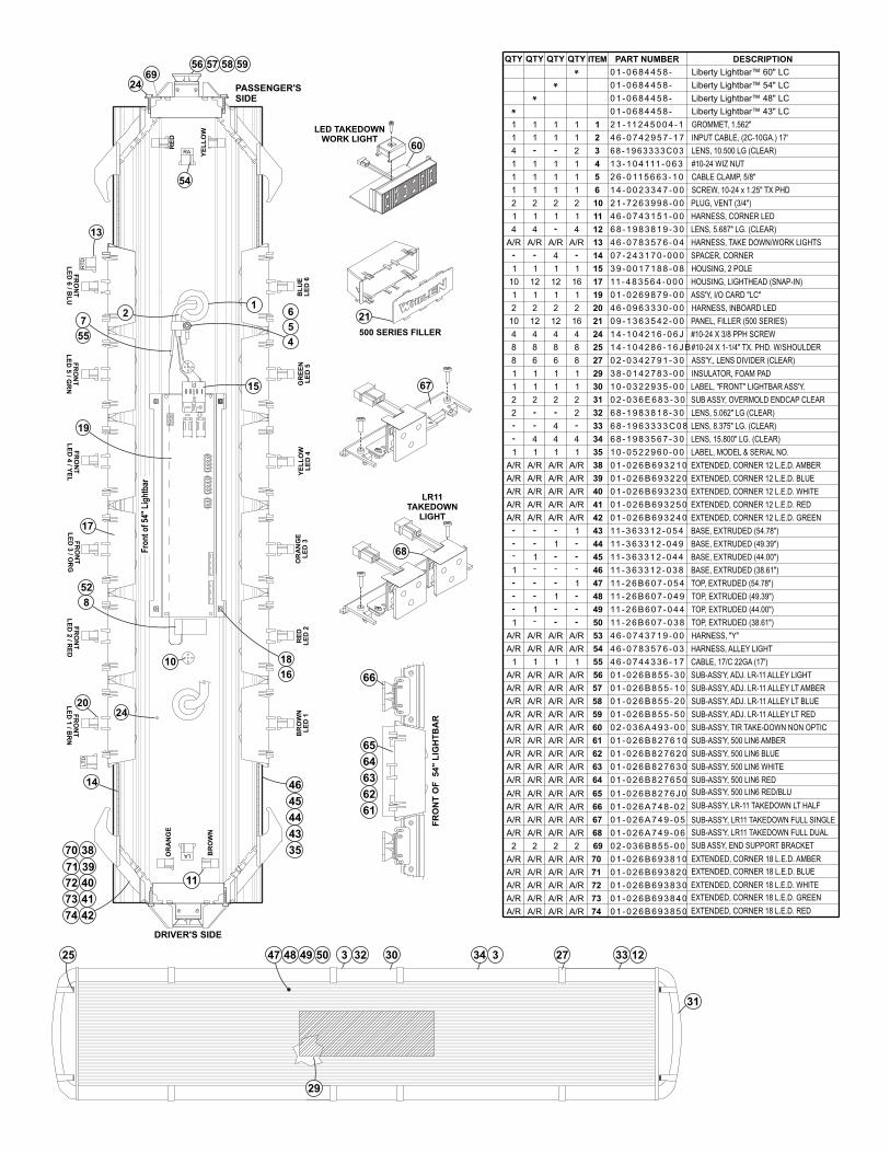
Page 9
13
PASSENGER'SSIDE
DRIVER'S SIDE
FR
ON
TL
ED
6/ B
LU
14
RE
DL
ED
2B
RO
WN
LE
D 1
18
16
OR
AN
GE
LE
D 3
YE
LL
OW
LE
D 4
GR
EE
NL
ED
5
17
FR
ON
TL
ED
3/ O
RG
FR
ON
TL
ED
2/ R
ED
24
LT
D
FR
ON
TL
ED
1/ B
RN
20
52
8
19
FR
ON
TL
ED
4/Y
EL
55
7
FR
ON
TL
ED
5/ G
RN
BL
UE
LE
D 6
RT
D
10
2
40
39
38
41
42
5
6
4
LED TAKEDOWNWORK LIGHT
60
LR11TAKEDOWN
LIGHT
68
500 SERIES FILLER
21
15
1
67
3 3248 49 50 34 3 27 33 12
31
25 47
29
30
Fro
nt
of
54"
Lig
htb
ar
72
71
70
73
74
RA
RE
D
YE
LL
OW
LAOR
AN
GE
BR
OW
N
11
56 57 58
24
5969
54
FR
ON
T O
F
54
" L
IGH
TB
AR
61
62
63
64
65
66
44
43
45
35
46
ITEM PART NUMBER DESCRIPTIONQTY QTY QTY QTY
Liberty Lightbar™ 60" LC0 1 - 0 6 8 4 4 5 8 -
Liberty Lightbar™ 54" LC0 1 - 0 6 8 4 4 5 8 -
Liberty Lightbar™ 48" LC0 1 - 0 6 8 4 4 5 8 -
Liberty Lightbar™ 43" LC0 1 - 0 6 8 4 4 5 8 -
2
1
A/R
16
16
PLUG, VENT (3/4")2 1 - 7 2 6 3 9 9 8 - 0 0
SPACER, CORNER
PANEL, FILLER (500 SERIES)
HARNESS, CORNER LED
HARNESS, TAKE DOWN/WORK LIGHTS
HOUSING, LIGHTHEAD (SNAP-IN)
0 7 - 2 4 3 1 7 0 - 0 0 0
4 6 - 0 7 4 3 1 5 1 - 0 0
4 6 - 0 7 8 3 5 7 6 - 0 4
11 - 4 8 3 5 6 4 - 0 0 0
0 9 - 1 3 6 3 5 4 2 - 0 0
1
4
8
8
2
1
1
4
1
#10-24 X 1-1/4" TX. PHD. W/SHOULDER
LABEL, "FRONT" LIGHTBAR ASS'Y.
#10-24 X 3/8 PPH SCREW
ASS'Y, I/O CARD "LC"
LENS, 15.800" LG. (CLEAR)
ASS'Y., LENS DIVIDER (CLEAR)
INSULATOR, FOAM PAD
SUB ASSY, OVERMOLD ENDCAP CLEAR
3 8 - 0 1 4 2 7 8 3 - 0 0
1 4 - 1 0 4 2 1 6 - 0 6 J
1 4 - 1 0 4 2 8 6 - 1 6 J B
0 2 - 0 3 4 2 7 9 1 - 3 0
1 0 - 0 3 2 2 9 3 5 - 0 0
0 1 - 0 2 6 9 8 7 9 - 0 0
6 8 - 1 9 8 3 5 6 7 - 3 0
0 2 - 0 3 6 E 6 8 3 - 3 0
LABEL, MODEL & SERIAL NO.1 0 - 0 5 2 2 9 6 0 - 0 0
HARNESS, INBOARD LED4 6 - 0 9 6 3 3 3 0 - 0 02
A/R
A/R
A/R
A/R
A/R 0 1 - 0 2 6 B 6 9 3 2 5 0
0 1 - 0 2 6 B 6 9 3 2 3 0
0 1 - 0 2 6 B 6 9 3 2 2 0
0 1 - 0 2 6 B 6 9 3 2 1 0
0 1 - 0 2 6 B 6 9 3 2 4 0 EXTENDED, CORNER 12 L.E.D. GREEN
EXTENDED, CORNER 12 L.E.D. AMBER
EXTENDED, CORNER 12 L.E.D. BLUE
EXTENDED, CORNER 12 L.E.D. WHITE
EXTENDED, CORNER 12 L.E.D. RED
TOP, EXTRUDED (54.78")
BASE, EXTRUDED (54.78")
11 - 2 6 B 6 0 7 - 0 5 4
11 - 3 6 3 3 1 2 - 0 5 41
1
2
6 8 - 1 9 6 3 3 3 3 C 0 8
6 8 - 1 9 8 3 8 1 8 - 3 0 LENS, 5.062" LG (CLEAR)
LENS, 8.375" LG. (CLEAR)
LENS, 5.687" LG. (CLEAR)6 8 - 1 9 8 3 8 1 9 - 3 04
2
1
A/R
4
12
2
1
12
4
8
A/R
A/R
A/R
A/R
4
6
1
2
1
1
4
A/R
2 2
1 1
A/R
4 4
A/R
10 12
2 2
1 1
10 12
4 4
8 8
A/R
A/R
A/R
A/R
8 6
1 1
2 2
1 1
2
1 1
4
A/R A/R
A/R
A/R
A/R
A/R
BASE, EXTRUDED (49.39")1
BASE, EXTRUDED (44.00")1-
BASE, EXTRUDED (38.61")---1
TOP, EXTRUDED (49.39")
TOP, EXTRUDED (44.00")
TOP, EXTRUDED (38.61")-
11 - 3 6 3 3 1 2 - 0 4 9
11 - 3 6 3 3 1 2 - 0 4 4
11 - 3 6 3 3 1 2 - 0 3 8
1
1
1
11 - 2 6 B 6 0 7 - 0 3 8
11 - 2 6 B 6 0 7 - 0 4 4
11 - 2 6 B 6 0 7 - 0 4 9
HOUSING, 2 POLE3 9 - 0 0 1 7 1 8 8 - 0 811 1 1
A/R A/R A/R A/R 4 6 - 0 7 8 3 5 7 6 - 0 3 HARNESS, ALLEY LIGHT
CABLE, 17/C 22GA (17')4 6 - 0 7 4 4 3 3 6 - 1 71 11 1
SUB-ASS'Y, ADJ. LR-11 ALLEY LIGHT0 1 - 0 2 6 B 8 5 5 - 3 0A/RA/RA/RA/R
4 6 - 0 7 4 3 7 1 9 - 0 0 HARNESS, "Y"
A/RA/R A/R SUB-ASS'Y, ADJ. LR-11 ALLEY LT AMBER0 1 - 0 2 6 B 8 5 5 - 1 0A/R
A/RA/R A/R SUB-ASS'Y, ADJ. LR-11 ALLEY LT BLUE0 1 - 0 2 6 B 8 5 5 - 2 0A/R
A/RA/R A/R SUB-ASS'Y, ADJ. LR-11 ALLEY LT RED0 1 - 0 2 6 B 8 5 5 - 5 0A/R
A/RA/R A/R SUB-ASS'Y, TIR TAKE-DOWN NON OPTIC0 2 - 0 3 6 A 4 9 3 - 0 0A/R
A/RA/R SUB-ASS'Y, 500 LIN6 AMBERA/RA/R 0 1 - 0 2 6 B 8 2 7 6 1 0
A/RA/R SUB-ASS'Y, 500 LIN6 BLUEA/RA/R 0 1 - 0 2 6 B 8 2 7 6 2 0
A/RA/R SUB-ASS'Y, 500 LIN6 WHITEA/RA/R 0 1 - 0 2 6 B 8 2 7 6 3 0
A/RA/R SUB-ASS'Y, 500 LIN6 REDA/RA/R 0 1 - 0 2 6 B 8 2 7 6 5 0
A/RA/R SUB-ASS'Y, 500 LIN6 RED/BLUA/RA/R 0 1 - 0 2 6 B 8 2 7 6 J 0
A/RA/R SUB-ASS'Y, LR-11 TAKEDOWN LT HALFA/RA/R 0 1 - 0 2 6 A 7 4 8 - 0 2
A/R A/R A/R A/R
A/R
A/R
A/R
A/R
SUB-ASS'Y, LR11 TAKEDOWN FULL DUALA/R
A/R
A/R
A/R
0 1 - 0 2 6 A 7 4 9 - 0 6
0 1 - 0 2 6 A 7 4 9 - 0 5 SUB-ASS'Y, LR11 TAKEDOWN FULL SINGLE
2 0 2 - 0 3 6 B 8 5 5 - 0 02 2 2 SUB ASSY, END SUPPORT BRACKET
A/R
A/R
A/R
A/R
A/R
A/R
A/R
A/R
A/R
A/R
EXTENDED, CORNER 18 L.E.D. WHITE
EXTENDED, CORNER 18 L.E.D. AMBER
EXTENDED, CORNER 18 L.E.D. GREEN
A/R 0 1 - 0 2 6 B 6 9 3 8 3 0A/R
0 1 - 0 2 6 B 6 9 3 8 1 0
0 1 - 0 2 6 B 6 9 3 8 2 0A/R
A/RA/R
A/R
0 1 - 0 2 6 B 6 9 3 8 4 0
0 1 - 0 2 6 B 6 9 3 8 5 0A/R
A/RA/R
A/R
13
11
10
12
14
15
17
19
20
24
21
25
27
35
29
30
31
32
33
34
39
38
40
42
41
44
43
45
46
47
48
49
50
53
54
55
56
57
58
59
60
61
62
63
64
65
66
68
67
69
72
70
71
73
74
EXTENDED, CORNER 18 L.E.D. BLUE
EXTENDED, CORNER 18 L.E.D. RED
1
4
1
1
1
1
1 1 11
1 1
1
1
1
1
2
1
3
2
1
1 5
4
1 1 1 6
INPUT CABLE, (2C-10GA.) 17'
GROMMET, 1.562"
#10-24 WIZ NUT
CABLE CLAMP, 5/8"
SCREW, 10-24 x 1.25" TX PHD
2 1 - 11 2 4 5 0 0 4 - 1
4 6 - 0 7 4 2 9 5 7 - 1 7
1 3 - 1 0 4 111 - 0 6 3
2 6 - 0 11 5 6 6 3 - 1 0
1 4 - 0 0 2 3 3 4 7 - 0 0
LENS, 10.500 LG (CLEAR)6 8 - 1 9 6 3 3 3 3 C 0 3