138 - komatsu · pdf filethe air-to-air charge cooler reduces ... pressurised cab an...
TRANSCRIPT
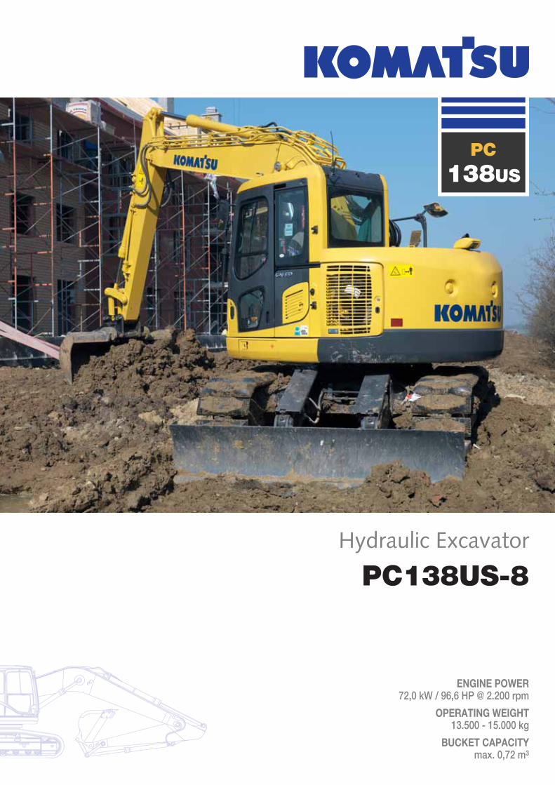
PC138US-8
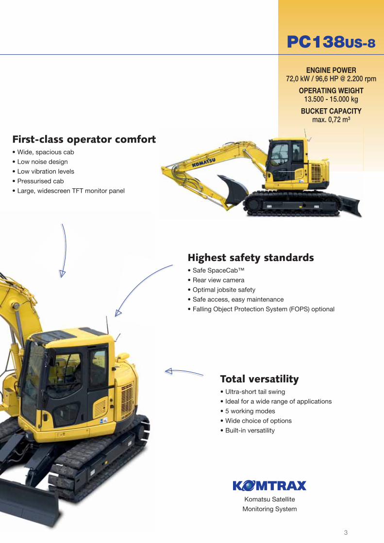
ENGINE POWER72,0 kW / 96,6 HP @ 2.200 rpm
OPERATING WEIGHT13.500 - 15.000 kg
BUCKET CAPACITYmax. 0,72 m³
Hydraulic Excavator
PC138US
2
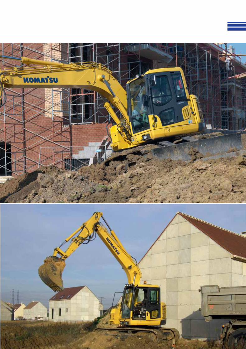
Walk-AroundThe Komatsu PC138US-8 hydraulic excavator was designed with an ultra-short tail swing
to meet the challenges of work in confi ned areas. With a near-zero tail swing radius, it’s the
ultimate machine for jobsite safety and is perfect for work on roadways, bridges, in urban
areas, or anywhere with limited work space. The PC138US-8 delivers the quality, performance
and productivity you can expect from Komatsu equipment.
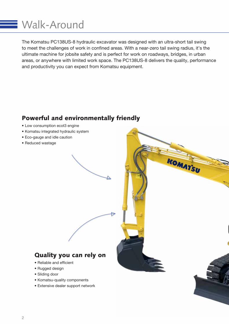
Powerful and environmentally friendly• Low consumption ecot3 engine
• Komatsu integrated hydraulic system
• Eco-gauge and idle caution
• Reduced wastage
Quality you can rely on• Reliable and effi cient
• Rugged design
• Sliding door
• Komatsu-quality components
• Extensive dealer support network
3
PC138US-8
Komatsu Satellite
Monitoring System
ENGINE POWER72,0 kW / 96,6 HP @ 2.200 rpm
OPERATING WEIGHT13.500 - 15.000 kg
BUCKET CAPACITYmax. 0,72 m³
Total versatility• Ultra-short tail swing
• Ideal for a wide range of applications
• 5 working modes
• Wide choice of options
• Built-in versatility
First-class operator comfort• Wide, spacious cab
• Low noise design
• Low vibration levels
• Pressurised cab
• Large, widescreen TFT monitor panel
Highest safety standards• Safe SpaceCab™
• Rear view camera
• Optimal jobsite safety
• Safe access, easy maintenance
• Falling Object Protection System (FOPS) optional
4
Total VersatilityIdeal for a wide range of applications
Powerful and precise, the Komatsu
PC138US-8 is equipped to effi -
ciently carry out any task your busi-
ness requires. On big sites or small,
for digging, trenching, landscaping
or site preparation, the Komatsu
original equipment hydraulic
system always ensures maximum
productivity and control.
5 working modes
Power, Lifting, Breaker, Attach-
ment, and Economy.
The PC138US-8 features 5 selecta-
ble working modes that optimise
performance and fuel usage. The
Economy mode can be adjusted
for an ideal balance between power
and economy to match your work.
The oil fl ow delivered to hydraulic
attachments is adjustable directly
on the class-leading wide screen
monitor panel.
Built-in versatility
To allow the use of many attach-
ments, such as buckets, breakers
or demolition tools, a power supply
for a hydraulic quick coupler with
adjustable pressure settings, and
an additional hydraulic circuit con-
trolled by a foot pedal and a sliding
joystick push button are standard
on the PC138US-8. A second op-
tional auxiliary line is also available
for attachments that require extra
hydraulic actuation.
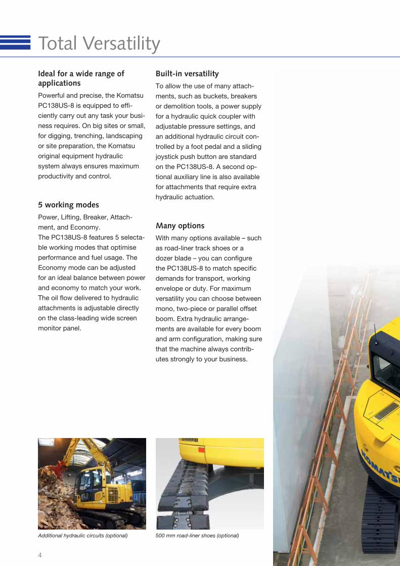
Many options
With many options available – such
as road-liner track shoes or a
dozer blade – you can confi gure
the PC138US-8 to match specifi c
demands for transport, working
envelope or duty. For maximum
versatility you can choose between
mono, two-piece or parallel offset
boom. Extra hydraulic arrange-
ments are available for every boom
and arm confi guration, making sure
that the machine always contrib-
utes strongly to your business.
500 mm road-liner shoes (optional)Additional hydraulic circuits (optional)
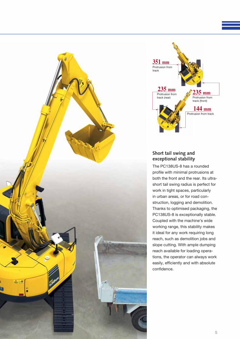
351 mm
235 mm 235 mm
144 mm
Protrusion from
track (rear) Protrusion from
track (front)
Protrusion from
track
Protrusion from track
5
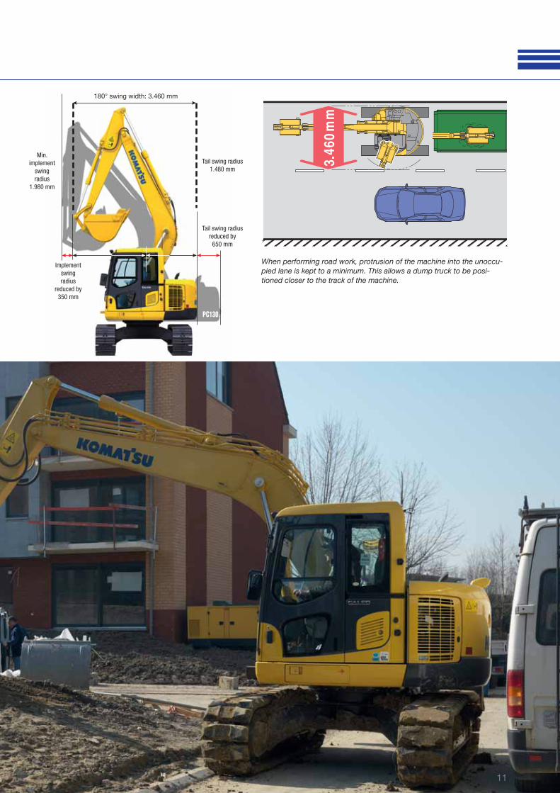
Short tail swing and exceptional stability
The PC138US-8 has a rounded
profi le with minimal protrusions at
both the front and the rear. Its ultra-
short tail swing radius is perfect for
work in tight spaces, particularly
in urban areas, or for road con-
struction, logging and demolition.
Thanks to optimised packaging, the
PC138US-8 is exceptionally stable.
Coupled with the machine’s wide
working range, this stability makes
it ideal for any work requiring long
reach, such as demolition jobs and
slope cutting. With ample dumping
reach available for loading opera-
tions, the operator can always work
easily, effi ciently and with absolute
confi dence.
6
Powerful and Environmentally Friendly
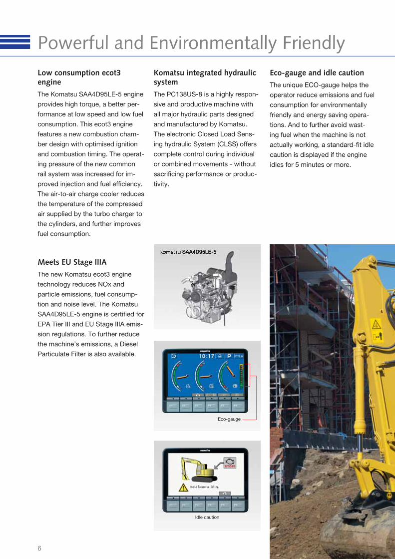
Eco-gauge
Idle caution
Komatsu integrated hydraulic system
The PC138US-8 is a highly respon-
sive and productive machine with
all major hydraulic parts designed
and manufactured by Komatsu.
The electronic Closed Load Sens-
ing hydraulic System (CLSS) offers
complete control during individual
or combined movements - without
sacrifi cing performance or produc-
tivity.
Eco-gauge and idle caution
The unique ECO-gauge helps the
operator reduce emissions and fuel
consumption for environmentally
friendly and energy saving opera-
tions. And to further avoid wast-
ing fuel when the machine is not
actually working, a standard-fi t idle
caution is displayed if the engine
idles for 5 minutes or more.
Low consumption ecot3 engine
The Komatsu SAA4D95LE-5 engine
provides high torque, a better per-
formance at low speed and low fuel
consumption. This ecot3 engine
features a new combustion cham-
ber design with optimised ignition
and combustion timing. The operat-
ing pressure of the new common
rail system was increased for im-
proved injection and fuel effi ciency.
The air-to-air charge cooler reduces
the temperature of the compressed
air supplied by the turbo charger to
the cylinders, and further improves
fuel consumption.
Meets EU Stage IIIA
The new Komatsu ecot3 engine
technology reduces NOx and
particle emissions, fuel consump-
tion and noise level. The Komatsu
SAA4D95LE-5 engine is certifi ed for
EPA Tier III and EU Stage IIIA emis-
sion regulations. To further reduce
the machine’s emissions, a Diesel
Particulate Filter is also available.
7
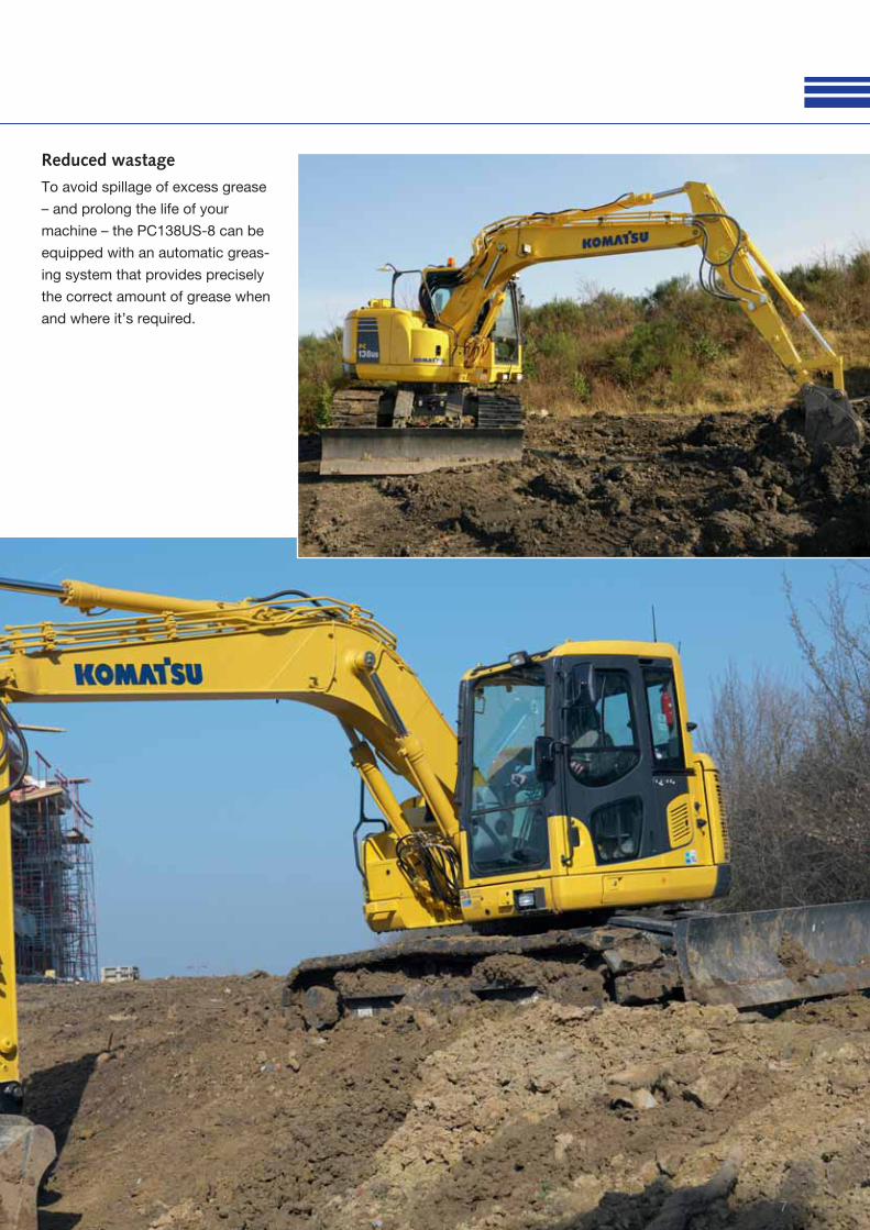
Reduced wastage
To avoid spillage of excess grease
– and prolong the life of your
machine – the PC138US-8 can be
equipped with an automatic greas-
ing system that provides precisely
the correct amount of grease when
and where it’s required.
8
First-Class Operator Comfort
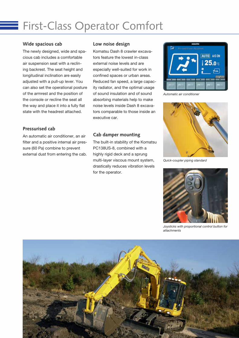
Quick-coupler piping standard
Joysticks with proportional control button for
attachments
Automatic air conditioner
Wide spacious cab
The newly designed, wide and spa-
cious cab includes a comfortable
air suspension seat with a reclin-
ing backrest. The seat height and
longitudinal inclination are easily
adjusted with a pull-up lever. You
can also set the operational posture
of the armrest and the position of
the console or recline the seat all
the way and place it into a fully fl at
state with the headrest attached.
Low noise design
Komatsu Dash 8 crawler excava-
tors feature the lowest in-class
external noise levels and are
especially well-suited for work in
confi ned spaces or urban areas.
Reduced fan speed, a large capac-
ity radiator, and the optimal usage
of sound insulation and of sound
absorbing materials help to make
noise levels inside Dash 8 excava-
tors comparable to those inside an
executive car.
Pressurised cab
An automatic air conditioner, an air
fi lter and a positive internal air pres-
sure (60 Pa) combine to prevent
external dust from entering the cab.
Cab damper mounting
The built-in stability of the Komatsu
PC138US-8, combined with a
highly rigid deck and a sprung
multi-layer viscous mount system,
drastically reduces vibration levels
for the operator.
9
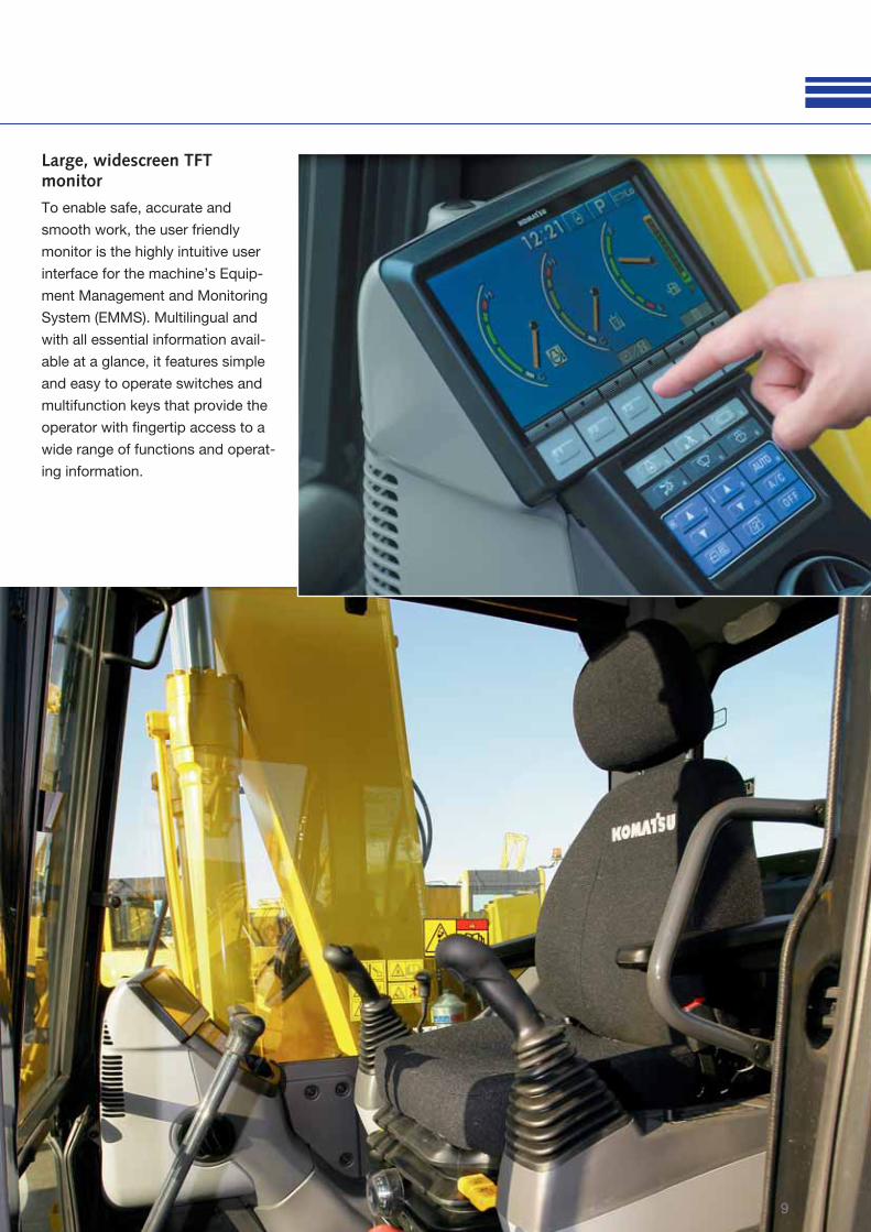
Large, widescreen TFT monitor
To enable safe, accurate and
smooth work, the user friendly
monitor is the highly intuitive user
interface for the machine’s Equip-
ment Management and Monitoring
System (EMMS). Multilingual and
with all essential information avail-
able at a glance, it features simple
and easy to operate switches and
multifunction keys that provide the
operator with fi ngertip access to a
wide range of functions and operat-
ing information.
10
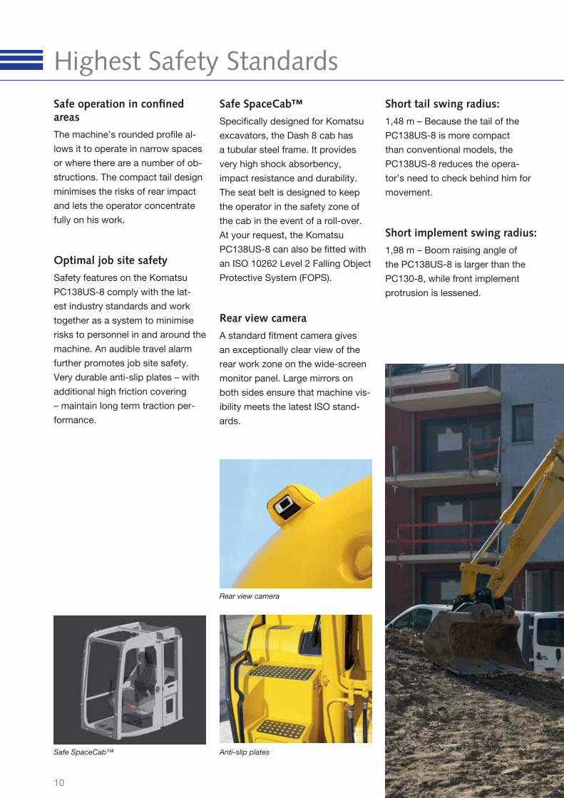
Highest Safety Standards
Safe SpaceCab™ Anti-slip plates
Safe SpaceCab™
Specifi cally designed for Komatsu
excavators, the Dash 8 cab has
a tubular steel frame. It provides
very high shock absorbency,
impact resistance and durability.
The seat belt is designed to keep
the operator in the safety zone of
the cab in the event of a roll-over.
At your request, the Komatsu
PC138US-8 can also be fi tted with
an ISO 10262 Level 2 Falling Object
Protective System (FOPS).
Rear view camera
A standard fi tment camera gives
an exceptionally clear view of the
rear work zone on the wide-screen
monitor panel. Large mirrors on
both sides ensure that machine vis-
ibility meets the latest ISO stand-
ards.
Optimal job site safety
Safety features on the Komatsu
PC138US-8 comply with the lat-
est industry standards and work
together as a system to minimise
risks to personnel in and around the
machine. An audible travel alarm
further promotes job site safety.
Very durable anti-slip plates – with
additional high friction covering
– maintain long term traction per-
formance.
Short implement swing radius:
1,98 m – Boom raising angle of
the PC138US-8 is larger than the
PC130-8, while front implement
protrusion is lessened.
Short tail swing radius:
1,48 m – Because the tail of the
PC138US-8 is more compact
than conventional models, the
PC138US-8 reduces the opera-
tor’s need to check behind him for
movement.
Rear view camera
Safe operation in confi ned areas
The machine’s rounded profi le al-
lows it to operate in narrow spaces
or where there are a number of ob-
structions. The compact tail design
minimises the risks of rear impact
and lets the operator concentrate
fully on his work.
11
3.46
0 m
m
180° swing width: 3.460 mm
Implement
swing
radius
reduced by
350 mm
Tail swing radius
reduced by
650 mm
Min.
implement
swing
radius
1.980 mm
Tail swing radius
1.480 mm
When performing road work, protrusion of the machine into the unoccu-
pied lane is kept to a minimum. This allows a dump truck to be posi-
tioned closer to the track of the machine.
12
Quality You Can Rely On
The sliding door facilitates easy entrance
in confi ned areas while reducing the risk of
damage on roadways. The cab also features
a sliding window.
Extensive dealer support network
The extensive Komatsu distribution
and dealer network is standing by
to help keep your fl eet in optimum
condition. Customised servic-
ing packages are available, with
express availability of spare parts,
to make sure that your Komatsu will
continue to perform at its peak.
Komatsu-quality components
With the latest computer design
techniques and a thorough test
programme, Komatsu’s global
know-how produces machines that
are designed, manufactured and
tested to meet your highest stand-
ards.
Rugged design
Maximum toughness and durabil-
ity – along with top class customer
service – are the cornerstones of
Komatsu’s philosophy. Single piece
plates and castings are used in key
areas of the machine’s structure for
good load distribution.
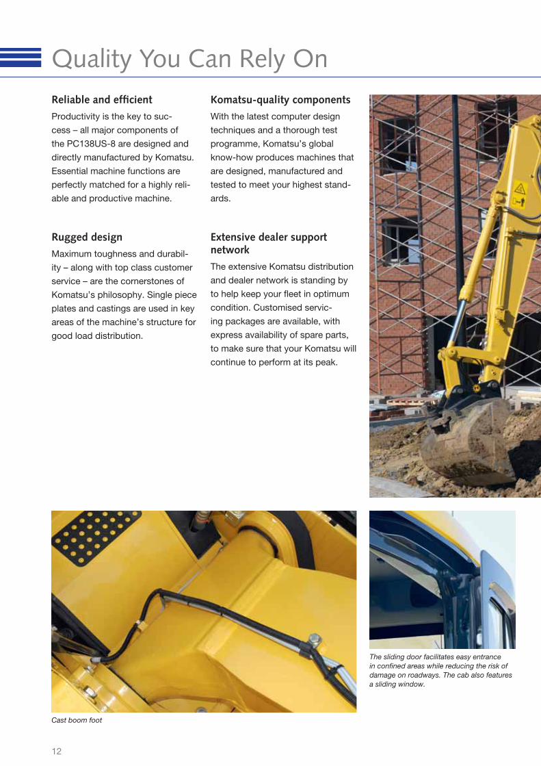
Reliable and effi cient
Productivity is the key to suc-
cess – all major components of
the PC138US-8 are designed and
directly manufactured by Komatsu.
Essential machine functions are
perfectly matched for a highly reli-
able and productive machine.
Cast boom foot
13
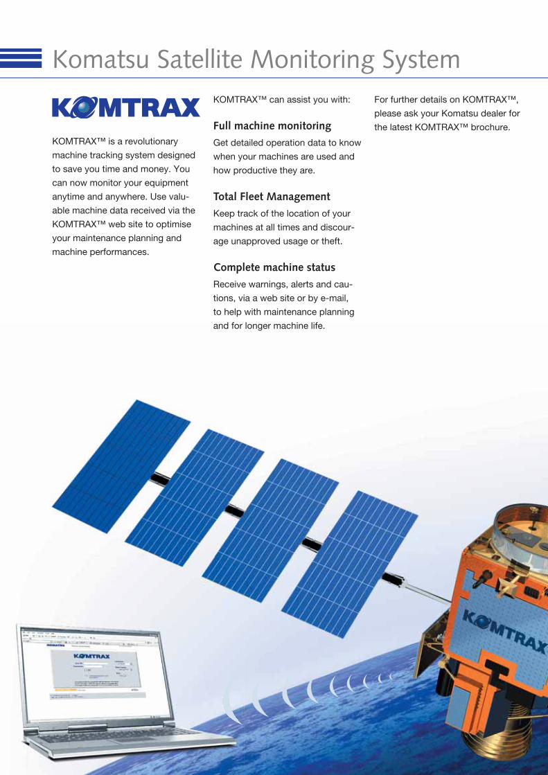
Komatsu Satellite Monitoring System
KOMTRAX™ is a revolutionary
machine tracking system designed
to save you time and money. You
can now monitor your equipment
anytime and anywhere. Use valu-
able machine data received via the
KOMTRAX™ web site to optimise
your maintenance planning and
machine performances.
KOMTRAX™ can assist you with:
Full machine monitoring
Get detailed operation data to know
when your machines are used and
how productive they are.
Total Fleet Management
Keep track of the location of your
machines at all times and discour-
age unapproved usage or theft.
Complete machine status
Receive warnings, alerts and cau-
tions, via a web site or by e-mail,
to help with maintenance planning
and for longer machine life.
For further details on KOMTRAX™,
please ask your Komatsu dealer for
the latest KOMTRAX™ brochure.
15
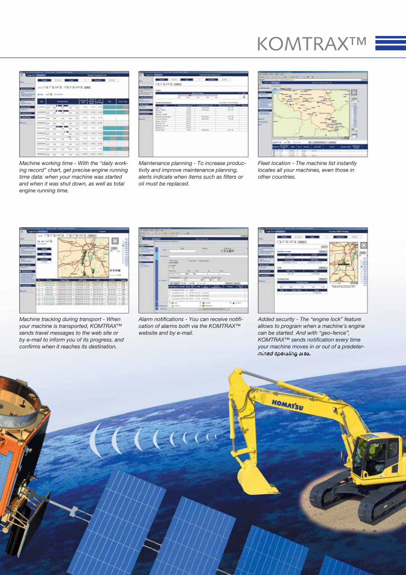
KOMTRAX™
Alarm notifi cations - You can receive notifi -
cation of alarms both via the KOMTRAX™
website and by e-mail.
Added security - The “engine lock” feature
allows to program when a machine’s engine
can be started. And with “geo-fence”,
KOMTRAX™ sends notifi cation every time
your machine moves in or out of a predeter-
Fleet location - The machine list instantly
locates all your machines, even those in
other countries.
Maintenance planning - To increase produc-
tivity and improve maintenance planning,
alerts indicate when items such as fi lters or
oil must be replaced.
Machine tracking during transport - When
your machine is transported, KOMTRAX™
sends travel messages to the web site or
by e-mail to inform you of its progress, and
confi rms when it reaches its destination.
Machine working time - With the “daily work-
ing record” chart, get precise engine running
time data: when your machine was started
and when it was shut down, as well as total
engine running time.
16
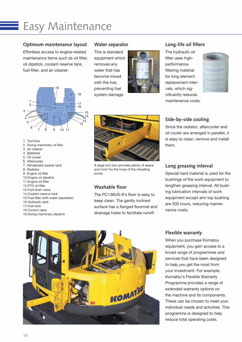
Easy MaintenanceWater separator
This is standard
equipment which
removes any
water that has
become mixed
with the fuel,
preventing fuel
system damage.
Side-by-side cooling
Since the radiator, aftercooler and
oil cooler are arranged in parallel, it
is easy to clean, remove and install
them.
Long-life oil fi lters
The hydraulic oil
fi lter uses high-
performance
fi ltering material
for long element
replacement inter-
vals, which sig-
nifi cantly reduces
maintenance costs.
Flexible warranty
When you purchase Komatsu
equipment, you gain access to a
broad range of programmes and
services that have been designed
to help you get the most from
your investment. For example,
Komatsu’s Flexible Warranty
Programme provides a range of
extended warranty options on
the machine and its components.
These can be chosen to meet your
individual needs and activities. This
programme is designed to help
reduce total operating costs.
3
2
11
1716
1514
5
7 98 6
10
1
4
1213
18
19
1. Tool box
2. Swing machinery oil fi ller
3. Air cleaner
4. Batteries
5. Oil cooler
6. Aftercooler
7. Windshield washer tank
8. Radiator
9. Engine oil fi ller
10. Engine oil dipstick
11. Engine oil fi lter
12. PTO oil fi ller
13. Fuel drain valve
14. Coolant reserve tank
15. Fuel fi lter (with water separator)
16. Hydraulic tank
17. Fuel tank
18. Control valve
19. Swing machinery dipstick
Optimum maintenance layout
Effortless access to engine-related
maintenance items such as oil fi lter,
oil dipstick, coolant reserve tank,
fuel fi lter, and air cleaner.
A large tool box provides plenty of space
and room for the hose of the refuelling
pump.
Long greasing interval
Special hard material is used for the
bushings of the work equipment to
lengthen greasing interval. All bush-
ing lubrication intervals of work
equipment except arm top bushing
are 500 hours, reducing mainte-
nance costs.
Washable fl oor
The PC138US-8’s fl oor is easy to
keep clean. The gently inclined
surface has a fl anged fl oormat and
drainage holes to facilitate runoff.
17
SERVICE REFILL CAPACITIES
Fuel tank...................................................................................195 ltr
Radiator...................................................................................12,4 ltr
Engine.........................................................................................11 ltr
Final drive (each side)................................................................2,5 ltr
Swing drive................................................................................2,5 ltr
Hydraulic tank ...........................................................................69 ltr
UNDERCARRIAGE
Construction...........................................X-frame centre section with
box section track-frames
Track assembly
Type .............................................................................Fully sealed
Shoes (each side) .......................................................................43
Tension ..................................Combined spring and hydraulic unit
Rollers
Track rollers (each side)................................................................7
Carrier rollers (each side) ..............................................................1
DRIVES AND BRAKES
Steering control ..................................2 levers with pedals giving full
independent control of each track
Drive method................................................................... Hydrostatic
Max. drawbar pull..............................................................12.500 kgf
Max. travel speeds
Lo / Hi .......................................................................2,9 / 5,1 km/h
SWING SYSTEM
Type............................................. Axial piston motor driving through
planetary double reduction gearbox
Swing lock..................................Electrically actuated wet multi-disc
brake integrated into swing motor
Swing speed...................................................................... 0 - 11 rpm
Swing torque .....................................................................3.357 kgm
ENVIRONMENT
Engine emissions ...................Fully complies with EU Stage IIIA and
EPA Tier III exhaust emission regulations
Noise levels
LwA external ................................100 dB(A) (2000/14/EC Stage II)
LpA operator ear........................72 dB(A) (ISO 6396 dynamic test)
HYDRAULIC SYSTEM
Type..............HydrauMind. Closed-centre system with load sensing
and pressure compensation valves
Main pump ........................................Variable-capacity piston pump
Pumps for.................. Boom, arm, bucket, swing, and travel circuits
Maximum pump fl ow.........................................................242 ltr/min
Hydraulic motors:
Travel ............................ 2 × axial piston motor with parking brake
Swing ..................1 × axial piston motor with swing holding brake
Relief valve settings:
Implement ...........................................................................355 bar
Travel ..................................................................................355 bar
Swing ..................................................................................276 bar
Pilot.......................................................................................33 bar
ENGINE
Model .......................................................... Komatsu SAA4D95LE-5
Type.............................. Common rail direct injection, water-cooled,
emissionised, turbocharged, after-cooled diesel
Engine power
at rated engine speed.................................................... 2.200 rpm
ISO 14396..........................................................72,0 kW / 96,6 HP
ISO 9249 (net engine power) .............................68,0 kW / 91,2 HP
No. of cylinders ................................................................................4
Bore × stroke.................................................................95 × 115 mm
Displacement...........................................................................3,26 ltr
Starter motor ...........................................................................4,5 kW
Alternator............................................................................ 24 V/60 A
Battery ........................................................................ 2 × 12 V/72 Ah
Air fi lter type .......................Double element type with monitor panel
dust indicator and auto dust evacuator
Specifi cations
18
Specifi cations
OPERATING WEIGHT (APPR.)
MONO BOOM TWO-PIECE BOOM OFFSET BOOM
Triple grouser shoes
Operating weight Ground pressure Operating weight Ground pressure Operating weight Ground pressure
500 mm 13.480 kg 0,43 kg/cm2 14.300 kg 0,46 kg/cm2 13.540 kg 0,43 kg/cm2
600 mm 13.670 kg 0,36 kg/cm2 14.490 kg 0,38 kg/cm² 13.730 kg 0,36 kg/cm²
700 mm 13.850 kg 0,31 kg/cm2 14.670 kg 0,33 kg/cm² 13.910 kg 0,31 kg/cm²
Operating weight including specifi ed work equipment, 2.500 mm arm
(offset boom: 2.100 mm arm), 470 kg backhoe bucket, rated capacity of
lubricants, coolant, full fuel tank and standard equipment.
Additional weight with blade: + 900 kg
Additional weight with 500 mm road-liner: + 130 kg
Additional counterweight: + 500 kg
BUCKET AND ARM COMBINATION PC138US-8
Width Capacity SAE Weight 2.100 mm 2.500 mm 3.000 mm
500 mm 0,25 m³ 335 kg � � �
600 mm 0,32 m³ 375 kg � � �
700 mm 0,40 m³ 390 kg � � �
800 mm 0,48 m³ 470 kg � � �
900 mm 0,56 m³ 475 kg � � �
1.000 mm 0,64 m³ 505 kg � � –
1.100 mm 0,72 m³ 560 kg � � –
Please consult with your distributor for the correct selection of buckets and
attachments to suit the application. The recommendations are given as a
guide only, based on typical operating conditions.
� Material weight up to 1,8 t/m³
� Material weight up to 1,5 t/m³
� Material weight up to 1,2 t/m³
– Not usable
A full range of Komatsu wear parts is available.
A wide range of attachments is available. Please consult
your distributor for details of the full range.
19
Dimensions
MACHINE DIMENSIONS MONO BOOM
E Overall height of cab 2.815 mm
F Clearance under counterweight 900 mm
G Ground clearance 395 mm
H Tail swing radius 1.480 mm
I Length of track on ground 2.880 mm
J Track length 3.610 mm
K Track gauge 1.990 mm
L Overall track width with 500 mm shoe 2.490 mm
Overall track width with 600 mm shoe 2.590 mm
Overall track width with 700 mm shoe 2.690 mm
M Shoe width 500, 600, 700 mm
N Grouser height 20 mm
O Machine tail height 1.980 mm
P Overall width of upper structure 2.490 mm
Q Distance, swing center to rear end (with add. counterweight) 1.545 mm
R Distance, swing center to blade 2.490 mm
S Blade, max. lifting height 470 mm
T Height of blade 590 mm
U Blade, max. digging depth 525 mm
Blade width (with 500 mm shoes) 2.490 mm
Blade width (with 600 mm shoes) 2.590 mm
MONO BOOM
Arm length 2.100 mm 2.500 mm 3.000 mm
A Transport length 7.275 mm 7.260 mm 7.160 mm
B Overall height (to top of boom) 2.690 mm 2.850 mm 3.210 mm
C Length on ground (transport) 4.660 mm 4.400 mm 4.290 mm
G
B
P
O
F
IJ
E
NMKL
C
H
A
TS
R
U
Q
20
MACHINE DIMENSIONS TWO-PIECE BOOM
E Overall height of cab 2.815 mm
F Clearance under counterweight 900 mm
G Ground clearance 395 mm
(H) Tail swing radius 1.545 mm
I Length of track on ground 2.880 mm
J Track length 3.610 mm
K Track gauge 1.990 mm
L Overall track width with 500 mm shoe 2.490 mm
Overall track width with 600 mm shoe 2.590 mm
Overall track width with 700 mm shoe 2.690 mm
M Shoe width 500, 600, 700 mm
N Grouser height 20 mm
O Machine tail height 2.075 mm
P Overall width of upper structure 2.490 mm
Q Distance, swing center to rear end (with add. counterweight) 1.545 mm
R Distance, swing center to blade 2.490 mm
S Blade, max. lifting height 470 mm
T Height of blade 590 mm
U Blade, max. digging depth 525 mm
Blade width (with 500 mm shoes) 2.490 mm
Blade width (with 600 mm shoes) 2.590 mm
TWO-PIECE BOOM
Arm length 2.100 mm 2.500 mm
A Transport length 7.460 mm 7.450 mm
B Overall height (to top of hose) 2.930 mm 3.050 mm
C Length on ground (transport) 4.935 mm 4.670 mm
TS
R
U
Q
G
B
P
O
F
IJ
E
NMKL
C
A
Dimensions
21
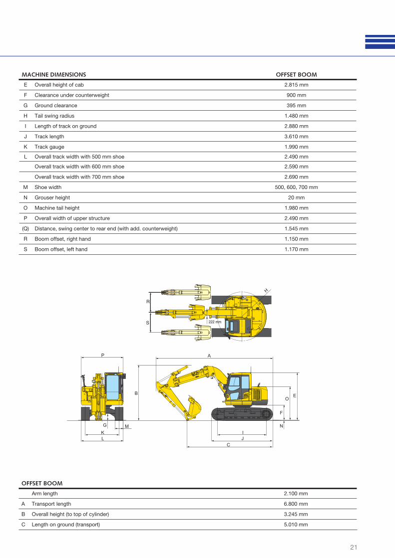
MACHINE DIMENSIONS OFFSET BOOM
E Overall height of cab 2.815 mm
F Clearance under counterweight 900 mm
G Ground clearance 395 mm
H Tail swing radius 1.480 mm
I Length of track on ground 2.880 mm
J Track length 3.610 mm
K Track gauge 1.990 mm
L Overall track width with 500 mm shoe 2.490 mm
Overall track width with 600 mm shoe 2.590 mm
Overall track width with 700 mm shoe 2.690 mm
M Shoe width 500, 600, 700 mm
N Grouser height 20 mm
O Machine tail height 1.980 mm
P Overall width of upper structure 2.490 mm
(Q) Distance, swing center to rear end (with add. counterweight) 1.545 mm
R Boom offset, right hand 1.150 mm
S Boom offset, left hand 1.170 mm
OFFSET BOOM
Arm length 2.100 mm
A Transport length 6.800 mm
B Overall height (to top of cylinder) 3.245 mm
C Length on ground (transport) 5.010 mm
G
B
P
O
F
IJ
E
NMKL
C
A
R
S 222 mm
H
22
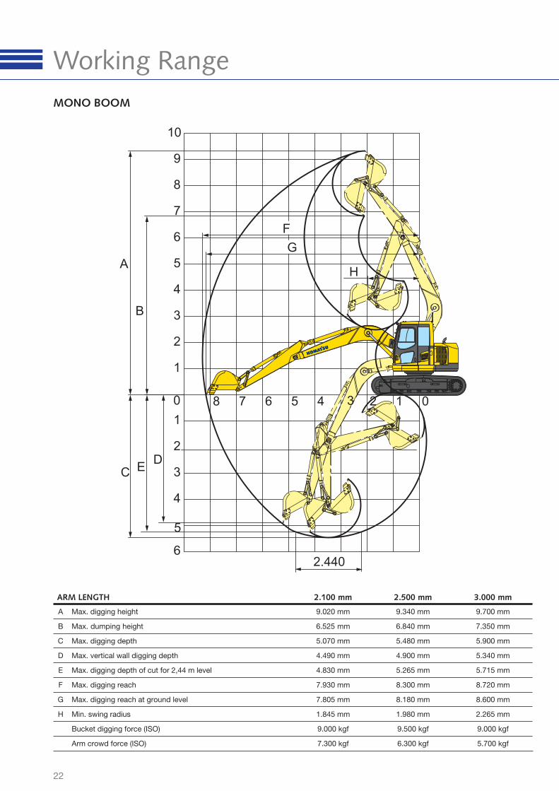
MONO BOOM
ARM LENGTH 2.100 mm 2.500 mm 3.000 mm
A Max. digging height 9.020 mm 9.340 mm 9.700 mm
B Max. dumping height 6.525 mm 6.840 mm 7.350 mm
C Max. digging depth 5.070 mm 5.480 mm 5.900 mm
D Max. vertical wall digging depth 4.490 mm 4.900 mm 5.340 mm
E Max. digging depth of cut for 2,44 m level 4.830 mm 5.265 mm 5.715 mm
F Max. digging reach 7.930 mm 8.300 mm 8.720 mm
G Max. digging reach at ground level 7.805 mm 8.180 mm 8.600 mm
H Min. swing radius 1.845 mm 1.980 mm 2.265 mm
Bucket digging force (ISO) 9.000 kgf 9.500 kgf 9.000 kgf
Arm crowd force (ISO) 7.300 kgf 6.300 kgf 5.700 kgf
F
EC
A
B
G
H
8 7 6 5 4 3 2 01
6
5
4
3
2
1
10
9
8
7
6
5
4
1
3
2
0
D
2.440
Working Range
23
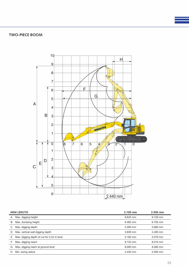
TWO-PIECE BOOM
ARM LENGTH 2.100 mm 2.500 mm
A Max. digging height 8.845 mm 9.130 mm
B Max. dumping height 6.465 mm 6.750 mm
C Max. digging depth 5.280 mm 5.680 mm
D Max. vertical wall digging depth 3.830 mm 4.400 mm
E Max. digging depth of cut for 2,44 m level 5.165 mm 5.570 mm
F Max. digging reach 8.135 mm 8.510 mm
G Max. digging reach at ground level 8.000 mm 8.380 mm
H Min. swing radius 2.430 mm 2.500 mm
8 7 6 5 4 2 1 0
6
5
4
3
2
1
10
9
8
7
6
5
4
3
2
1
0 3
D
C
A
B
G
F
E
2.440 mm
H
24
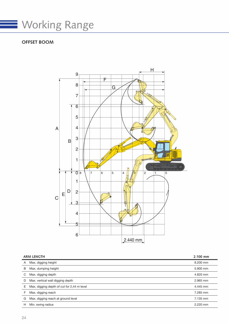
OFFSET BOOM
ARM LENGTH 2.100 mm
A Max. digging height 8.200 mm
B Max. dumping height 5.900 mm
C Max. digging depth 4.820 mm
D Max. vertical wall digging depth 2.965 mm
E Max. digging depth of cut for 2,44 m level 4.445 mm
F Max. digging reach 7.285 mm
G Max. digging reach at ground level 7.135 mm
H Min. swing radius 2.220 mm
8 7 6 5 4 2 1 0
6
5
4
3
2
1
9
8
7
6
5
4
3
2
1
0 3
D
C
A
B
E
2.440 mm
G
F
H
Working Range

25
6,0 m kg *1.620 *1.620 *2.810 *2.8104,5 m kg *1.510 1.480 *2.880 1.930 *3.040 *3.0403,0 m kg *1.530 1.260 2.240 1.380 2.960 1.870 *3.730 3.090 *4.970 *4.9701,5 m kg *1.630 1.170 2.190 1.330 2.850 1.770 *4.600 2.850 *7.270 5.430
0,0 m kg *1.860 1.180 2.130 1.280 2.750 1.680 4.380 2.650 *7.350 4.990
-1,5 m kg 2.190 1.310 2.690 1.620 4.270 2.550 *8.020 4.870 *4.070 *4.070-3,0 m kg 2.740 1.660 4.270 2.550 *6.770 4.920 *6.870 *6.870
-4,5 m kg *2.500 *2.500 *4.180 *4.180
6,0 m kg *2.060 *2.060 *3.270 3.2204,5 m kg *1.920 1.730 *2.890 1.890 *3.460 3.200 *3.960 *3.9603,0 m kg *1.950 1.450 2.940 1.860 *4.140 3.050 *5.870 *5.8701,5 m kg *2.120 1.350 2.850 1.780 4.590 2.840 *7.960 5.330
0,0 m kg 2.250 1.370 2.780 1.710 4.300 2.580 *6.750 5.030
-1,5 m kg 2.540 1.550 2.740 1.680 4.340 2.620 *7.740 4.990 *4.710 *4.710-3,0 m kg *3.130 2.060 *4.160 2.650 *6.140 5.090 *8.310 *8.310
-4,5 m kg
6,0 m kg *2.620 *2.620 *3.530 3.150 *3.860 *3.8604,5 m kg *2.420 1.950 *3.780 3.150 *4.560 *4.5603,0 m kg *2.460 1.610 2.910 1.830 *4.420 3.000 *6.530 5.8201,5 m kg 2.410 1.490 2.840 1.770 4.550 2.810
0,0 m kg 2.480 1.520 2.780 1.710 4.260 2.560 *6.240 5.000
-1,5 m kg 2.850 1.750 4.230 2.530 *7.300 5.020 *5.280 *5.280-3,0 m kg *3.190 2.430 *3.660 2.700 *5.440 5.150
-4,5 m kg
Lifting Capacity
* Load is limited by hydraulic capacity rather than tipping.
Ratings are based on SAE Standard No. J1097.
Rated loads do not exceed 87% of hydraulic lift capacity or 75% of tipping load.
When removing bucket, linkage or cylinder, lifting capacities can be increased by their respective weights
With 500 mm shoes
A
B
C
– Reach from swing center
– Bucket hook height
– Lifting capacities, including bucket (450 kg), bucket linkage and bucket cylinder
– Rating over front
– Rating over side
– Rating at maximum reach
MONO BOOM
3.000 mm
450 kg0,5 m³
2.500 mm
450 kg0,5 m³
2.100 mm
450 kg0,5 m³
Arm length
7,0 m 6,0 m 4,5 m 3,0 m 1,5 m
26
TWO-PIECE BOOM
* Load is limited by hydraulic capacity rather than tipping.
Ratings are based on SAE Standard No. J1097.
Rated loads do not exceed 87% of hydraulic lift capacity or 75% of tipping load.
When removing bucket, linkage or cylinder, lifting capacities can be increased by their respective weights
With 500 mm shoes
A
B
C
– Reach from swing center
– Bucket hook height
– Lifting capacities, including bucket (450 kg), bucket linkage and bucket cylinder
– Rating over front
– Rating over side
– Rating at maximum reach
7,5 m kg *2.500 *2.500
6,0 m kg *2.050 *2.050 *3.100 *3.1004,5 m kg *1.900 1.550 2.750 2.050 *3.350 *3.350
3,0 m kg 1.800 1.300 2.700 1.950 *4100 3.250 *5.850 *5.850
1,5 m kg 1.700 1.200 1.700 1.200 2.550 1.850 4.200 3.000
0,0 m kg 1.700 1.200 1.700 1.200 2.450 1.750 4.000 2.800
-1,5 m kg 1.900 1.350 2.400 1.700 3.900 2.700 *7.500 4.600
-3,0 m kg 2.400 1.700 2.450 1.700 3.900 2.700 *7.450 5.300
-4,5 m kg
7,5 m kg *3.200 *3.200
6,0 m kg *2.500 2.350 *3.500 *3.5004,5 m kg *2.350 1.700 2.700 2.000 *3.700 3.450
3,0 m kg 2.000 1.450 2.650 1.950 4.350 3.200 *6.550 6.300
1,5 m kg 1.850 1.350 2.550 1.850 4.150 2.950
0,0 m kg 1.900 1.350 2.450 1.750 3.950 2.750
-1,5 m kg 2.150 1.500 2.450 1.750 3.900 2.700 *7.750 4.650
-3,0 m kg 2.800 2.000 3.950 2.750 *6.850 5.400
-4,5 m kg
2.500 mm
450 kg0,5 m³
2.100 mm
450 kg0,5 m³
Lifting Capacity
Arm length
7,5 m 6,0 m 4,5 m 3,0 m 1,5 m
27
OFFSET BOOM
When removing bucket, linkage or cylinder, lifting capacities can be increased by their respective weights
With 500 mm shoes
A
B
C
– Reach from swing center
– Bucket hook height
– Lifting capacities, including bucket (450 kg), bucket linkage and bucket cylinder
– Rating over front
– Rating over side
– Rating at maximum reach
* Load is limited by hydraulic capacity rather than tipping.
Ratings are based on SAE Standard No. J1097.
Rated loads do not exceed 87% of hydraulic lift capacity or 75% of tipping load.
6,0 m kg *2.140 *2.140 *3.130 *3.1304,5 m kg *2.060 *2.060 *2.210 1.810 *3.210 *3.210 *3.160 *3.1603,0 m kg *2.190 1.750 *2.890 1.790 *3.780 3.030 *5.070 *5.0701,5 m kg *2.530 1.540 2.770 1.670 4.520 2.740
0,0 m kg 2.590 1.530 2.650 1.570 4.250 2.500
-1,5 m kg 2.990 1.750 4.130 2.390 *7.590 4.600
-3,0 m kg *4.090 2.560 *3.780 2.450 *6.120 4.740 *8.020 *8.020
-4,5 m kg
2.100 mm
450 kg0,5 m³
Arm length
7,0 m 6,0 m 4,5 m 3,0 m 1,5 m
Komatsu Europe
International NVMechelsesteenweg 586
B-1800 VILVOORDE (BELGIUM)
Tel. +32-2-255 24 11
Fax +32-2-252 19 81
www.komatsu.eu
Materials and specifi cations are subject to change without notice.
is a trademark of Komatsu Ltd. Japan.
UESS12703 08/2009
Printed in Europe – This specifi cation sheet may contain attachments and optional equipment that are not available in your area.
Please consult your local Komatsu distributor for those items you may require. Materials and specifi cations are subject to change without notice.
Standard and Optional Equipment
Your Komatsu partner:
PC138US-8Hydraulic Excavator
Further equipment on request
standard equipment optional equipment
ENGINEKomatsu SAA4D95LE-5, 72 kW turbocharged
common rail direct injection diesel engine,
EU Stage IIIA compliant
Suction type cooling fan with radiator fl y screen
Automatic engine warm-up system
Engine overheat prevention system
Fuel control dial
Auto-deceleration function
Engine key stop
Engine ignition can be password secured on
request
Alternator 24 V/60 A
Starter motor 24 V/4,5 kW
Batteries 2 × 12 V/72 Ah
Diesel particulate fi lter
HYDRAULIC SYSTEMElectronic closed-centre load sensing (E-CLSS)
hydraulic system (HydrauMind)
Pump and engine mutual control (PEMC) system
5-working mode selection system; Power mode,
economy mode, breaker mode, attachment mode
and lifting mode
One additional 2-way full-fl ow service spool with
attachment lines on boom and arm and pedal in
cab (HCU A)
Adjustable PPC wrist control levers for arm, boom,
bucket and swing, with sliding proportional control
for attachments and 3 auxiliary buttons
Quick-coupler piping
Additional hydraulic circuit
DRIVES AND BRAKESHydrostatic, 3-speed travel system with automatic
shift and planetary gear type fi nal drives, and
hydraulic travel and parking brakes
PPC control levers and pedals for steering and
travel
CABINReinforced safety SpaceCab™; Highly pressurised
and tightly sealed hyper viscous mounted cab
with tinted safety glass windows, large roof hatch,
pull-up type front window with locking device,
removable lower window, front window wiper
with intermittent feature, cigarette lighter, ashtray,
luggage shelf, fl oor mat
Suspension seat with lumbar support, height
adjustable arm rests and retractable seat belt
Automatic climate control system
12 Volt power supply
Beverage holder
Radio
Heated air suspension seat
Lower wiper
SERVICE AND MAINTENANCEAutomatic fuel line de-aeration
Double element type air cleaner with dust indicator
and auto dust evacuator
KOMTRAX™ - Komatsu satellite monitoring system
Multi-function video compatible colour monitor with
Equipment Management and Monitoring System
(EMMS) and effi ciency guidance
Toolkit and spare parts for fi rst service
SAFETY EQUIPMENTRear view camera system
Electric horn
Overload warning device
Lockable fuel cap and covers
Audible travel alarm
Boom safety valves
Large handrails, rear-view mirrors
Battery main switch
Arm safety valve
OPG Level II front guard (FOPS)
OPG Level II top guard (FOPS)
LIGHTING SYSTEMWorking lights: 1 revolving frame and 1 boom (r.h.)
Additional working lights: 5 cab roof, 1 boom
(l.h.), 1 counterweight (rear), additional revolving
frame (l.h.), beacon and harness for 2 lamps (not
included) in boom foot area
OTHER EQUIPMENTRemote greasing for swing circle and pins
Electric refuelling pump with automatic shut off
function
Standard colour scheme and decals
Parts book and operator manual
Additional counterweight 500 kg
UNDERCARRIAGETrack frame under-guards
500 mm triple grouser shoes
600, 700 mm triple grouser shoes
500 mm road-liner (rubber) shoes
WORK EQUIPMENT3,0 m arm, HCU assembly includes piping for one
additional function
Mono boom
Two-piece boom
Offset boom
2,1 m; 2,5 m; 3,0 m arms (HCU assembly includes
piping for one additional function)
Dozer blade (with 500 or 600 mm shoes)
Komatsu buckets
Komatsu breakers