1394ta iicp specification for the instrument & industrial...
TRANSCRIPT

10/08/99 IICP version 1.0 1394TA document 1999016
Copyright © 1998-1999 1394TA Page 1 of 93This is an approved 1394TA specification
1394TA IICPSpecification for the Instrument &Industrial Control Protocol
Specification 1.00October 8, 1999Sponsored by:Instrumentation and Industrial Control Working Group (II-WG) of the 1394 Trade Association
Approved for Release by:The II-WG and the 1394 Trade Association have approved this document for release.
Abstract:This document describes a lightweight protocol for efficient asynchronous communication toelectronic instrumentation and industrial control devices using the IEEE-1394 serial bus. Thisprotocol uses a dual-duplex plug structure for transfer of data and command/control sequences.A consumer communicates to a connected producer the space available in a consumer segmentbuffer, so all communication is flow controlled. This document specifies the establishment, use,and maintenance of the plugs. This document also specifies the discovery process for nodesimplementing the protocol, and furthermore, specifies the discovery and operation of minimalmemory mapped nodes.
Keywords: protocol, instrument, industrial control, 1394, asynchronous, lightweight, flow control,discovery, memory mapped
1394 Trade Association2350 Mission College Blvd. , Suite 350 , Santa Clara, CA, 95054, USAhttp://www.1394TA.org
Copyright © 1998-1999 by the 1394 Trade Association. Permission is granted to members of the 1394 Trade Associationto reproduce this document for their own use or the use of other 1394 Trade Association members only, provided thisnotice is included. All other rights reserved. Duplication for sale, or for commercial or for-profit use is strictly prohibitedwithout the prior written consent of the 1394 Trade Association.

10/08/99 IICP version 1.0 1394TA document 1999016
Copyright © 1998-1999 1394TA Page 2 of 93This is an approved 1394TA specification
1394 Trade Association Specifications are developed with Working Groups of the 1394 TradeAssociation, a non-profit industry association devoted to the promotion of and growth of the market for IEEE1394 computer products. Participants in working groups serve voluntarily and without compensation fromthe Trade Association. Most participants represent member organizations of the 1394 Trade Association.The specifications developed within the working groups represent a consensus of the expertise representedby the participants.
Use of a 1394 Trade Association Specification is wholly voluntary. The existence of a 1394 TradeAssociation Specification is not meant to imply that there are not other ways to produce, test, measure,purchase, market, or provide other goods and services related to the scope of the 1394 Trade AssociationSpecification. Furthermore, the viewpoint expressed at the time a specification is approved and issued issubject to change, brought about through developments in the state of the art and comments received fromusers of the specification. Users are cautioned to check to determine that they have the latest revision of any1394 Trade Association Specification.
Comments for revision of 1394 Trade Association Specifications are welcome from any interested party,regardless of membership affiliation with the 1394 Trade Association. Suggestions for changes indocuments should be in the form of a proposed change of a proposed change of text, together withappropriate supporting comments.
Interpretations: Occasionally, questions may arise about the meaning of specifications in relationship tospecific applications. When the need for interpretations is brought to the attention of the 1394 TradeAssociation, the Association initiates action to prepare appropriate responses.
Comments on specifications and requests for interpretations should be addressed to:
Editor, 1394 Trade AssociationRegency Plaza Suite 3502350 Mission College Blvd.Santa Clara, California 95054, USA
1394 Trade Association Specifications are adopted by the 1394 Trade Association withoutregard to patents which may exist on articles, materials or processes or to other proprietaryintellectual property which may exist within a specification. Adoption of a specification by the1394 Trade Association does not assume any liability to any patent owner or any obligationwhatsoever to those parties who rely on the specification documents. Readers of thisdocument are advised to make an independent determination regarding the existence ofintellectual property rights which may be infringed by conformance to this specification.

10/08/99 IICP version 1.0 1394TA document 1999016
Copyright © 1998-1999 1394TA Page 3 of 93This is an approved 1394TA specification
Introduction
The 1394TA II-WG was formed with the following charter:• Investigate protocols specific to instrumentation and industrial control applications.• Efficiently and robustly transfer data in a standard way between serial bus compliant nodes.• Use enhanced features of the IEEE1394 architecture to encapsulate existing command sets
and protocols, for example GPIB.• Expand into native IEEE1394 usage models to adopt and implement new features now
possible.
The II-WG decided in September 1998 to first create a baseline document. Higher level protocoldocuments, for example GPIB using IICP (IICP488), will follow, building on this baseline IICPdocument.
Committee Membership
Chairman: Andreas SchloissnikCompany: 3A InternationalEmail: [email protected]: (602) 437-1751
Secretary: Gary SakmarCompany: Keithley InstrumentsEmail: [email protected]: (440) 542-8016
Editor: Andy PurcellCompany: Hewlett-PackardEmail: [email protected]: (970) 679-5976
II-WG Reflector: '[email protected]'
The following individuals are acknowledged for their contributions to this specification:
Greg HillSteve SchinkDave JamesAndrew Thomson

10/08/99 IICP version 1.0 1394TA document 1999016
Copyright © 1998-1999 1394TA Page 4 of 93This is an approved 1394TA specification
Table of contents
1.1 Scope ......................................................................................................................................... 8
3.1 Word usage – shall, should, may, can........................................................................................ 103.2 Definitions................................................................................................................................ 103.3 Numeric notation...................................................................................................................... 113.4 State machine notation.............................................................................................................. 12
3.4.1 State machine logic.......................................................................................................... 123.4.2 State machine transitions – text description ...................................................................... 12
3.5 Packets with data payload ......................................................................................................... 133.6 Reserved fields ......................................................................................................................... 133.7 Figures depicting 1394 address space ........................................................................................ 13
4.1 Configuration ROM.................................................................................................................. 144.1.1 Configuration ROM structure .......................................................................................... 144.1.2 Multi-protocol devices ..................................................................................................... 194.1.3 Read operations on the configuration ROM...................................................................... 194.1.4 Device aliases (nicknames) in the configuration ROM...................................................... 19
5.1 Interrupt mechanism for IICP memory mapped devices ............................................................. 20interrupt_enable register ................................................................................................................ 20interrupt_handlr register ................................................................................................................ 20
5.2 1394 memory mapped only IICP device limitations................................................................... 21
6.1 Introduction to IICP connection plugs ....................................................................................... 226.1.1 IICP frames ..................................................................................................................... 226.1.2 Plug architecture.............................................................................................................. 24
6.2 Plug register details .................................................................................................................. 256.2.1 ProducerLimits register.................................................................................................... 256.2.2 SmallFramePageTableElement register ............................................................................ 266.2.3 SmallFrameProducer register ........................................................................................... 266.2.4 LargeFrameProducer register ........................................................................................... 276.2.5 LargeFramePageTableElement registers........................................................................... 276.2.6 SmallFrameConsumer register ......................................................................................... 286.2.7 LargeFrameConsumer register ......................................................................................... 28
6.3 1394 operations allowed on plug registers ................................................................................. 296.3.1 Efficient updating of plug registers .................................................................................. 29
6.4 Large frame transfers ................................................................................................................ 296.4.1 Sequential and non-sequential writes for large frame transfers .......................................... 30
6.5 Small frame transfers ................................................................................................................ 316.6 Mixing of large frame mode and small frame transfer mode....................................................... 326.7 Consumer segment buffers........................................................................................................ 336.8 Plug schematics ........................................................................................................................ 336.9 Multiple devices ....................................................................................................................... 346.10 Connection variations........................................................................................................... 346.11 Creating an IICP connection................................................................................................. 35
6.11.1 Connection creation sequence .......................................................................................... 366.11.2 Note on dataFrameSize, controlFrameSize and sizing of consumer buffers ....................... 42
6.12 Connection deactivation ....................................................................................................... 436.13 Connection reactivation........................................................................................................ 43
6.13.1 Reactivation sequence...................................................................................................... 446.14 Disconnecting IICP connections ........................................................................................... 46
6.14.1 Disconnection sequence................................................................................................... 466.15 Obtaining connection information ........................................................................................ 49
1. Instrumentation and industrial control protocol (IICP) overview....................................................... 8
2. References ...................................................................................................................................... 93. Document definitions and notation ................................................................................................ 10
4. Functional discovery ..................................................................................................................... 14
5. IICP 1394 memory-mapped I/O..................................................................................................... 20
6. IICP asynchronous plug connections ............................................................................................. 22

10/08/99 IICP version 1.0 1394TA document 1999016
Copyright © 1998-1999 1394TA Page 5 of 93This is an approved 1394TA specification
6.15.1 Connection information sequence .................................................................................... 496.16 Summary of connection packet fields ................................................................................... 53
6.16.1 ConnectPktId values ........................................................................................................ 536.16.2 connectRequestStatus values............................................................................................ 53
6.17 Miscellaneous macro values ................................................................................................. 546.18 Connection manager state machine....................................................................................... 55
6.18.1 Connection manager state machine: request startup .......................................................... 566.18.2 Connection manager state machine: LockRegisters(device1,device2)................................ 576.18.3 Connection manager state machine: UnlockRegisters()..................................................... 596.18.4 Connection manager state machine: creating a plug.......................................................... 616.18.5 Connection manager state machine: reactivating a connection .......................................... 636.18.6 Connection manager state machine: stopping a connection ............................................... 646.18.7 Connection manager state machine: get plug information ................................................. 656.18.8 Connection manager state machine: get specific plug information .................................... 666.18.9 Connection manager state machine: CM_busReset() ........................................................ 66
6.19 Connection client state machine............................................................................................ 676.19.1 Locking of connection register and waiting for request ..................................................... 686.19.2 Connection client request == CREQ1............................................................................... 696.19.3 Connection client request == CREQ2............................................................................... 706.19.4 Connection client request == REACT .............................................................................. 706.19.5 Connection client request == STOP ................................................................................. 716.19.6 Connection client request == FREE ................................................................................. 716.19.7 Connection client request == GETINFO .......................................................................... 726.19.8 Connection client request == GETPLUGINFO................................................................. 72
6.20 Consumer state machine....................................................................................................... 736.20.1 Large frame consumer state machine terminology ............................................................ 736.20.2 Large frame consumer state machine................................................................................ 746.20.3 Small frame consumer state machine terminology ............................................................ 766.20.4 Small frame consumer state machine................................................................................ 77
6.21 Producer state machines ....................................................................................................... 796.21.1 Large frame producer state machine terminology.............................................................. 796.21.2 Large frame producer state machine, states LFP0 – LFP4................................................. 806.21.3 Large frame producer state machine, states LFP4 – LFP7................................................. 816.21.4 Small frame producer state machine terminology ............................................................. 846.21.5 Small frame producer state machine, states SFP0 – SFP4 ................................................. 856.21.6 Small frame producer state machine, states SFP4 – SFP7 ................................................. 86
7.1 IICP control request.................................................................................................................. 887.1.1 Initialization of IICP layer ............................................................................................... 887.1.2 Configure the IICP layer .................................................................................................. 88
7.2 IICP open request ..................................................................................................................... 897.3 IICP close request..................................................................................................................... 907.4 IICP write data frame request.................................................................................................... 907.5 IICP write control frame request ............................................................................................... 907.6 IICP read data frame request ..................................................................................................... 907.7 IICP CREQ1 indication ............................................................................................................ 907.8 IICP connection established indication ...................................................................................... 907.9 IICP stop indication .................................................................................................................. 917.10 IICP err indication................................................................................................................ 917.11 IICP control frame received indication.................................................................................. 91
8.1 Application-level retries............................................................................................................ 928.2 1394 bus resets ......................................................................................................................... 92
8.2.1 Bus reset while connection registers are locked ................................................................ 928.2.2 Bus reset during updates of plug fields ............................................................................. 928.2.3 Bus reset while transferring data ...................................................................................... 92
7. IICP services (informative)............................................................................................................ 88
8. Error recovery ............................................................................................................................... 92

10/08/99 IICP version 1.0 1394TA document 1999016
Copyright © 1998-1999 1394TA Page 6 of 93This is an approved 1394TA specification
8.2.4 Duplicate writes............................................................................................................... 93
List of figures
Figure 1 -- State machine notation .............................................................................................12Figure 2 -- 1394 block write with header and payload.................................................................13Figure 3 -- 1394 block write (short form) ....................................................................................13Figure 4 -- Figures depicting 1394 address space ......................................................................13Figure 5 -- IICP configuration ROM format (one unit directory) ...................................................14Figure 6 -- Root directory ...........................................................................................................15Figure 7 – IICP unit directory .....................................................................................................16Figure 8 -- IICP_details..............................................................................................................16Figure 9 -- Connection register In 1394 space............................................................................17Figure 10 -- IICP_Capabilities entry ...........................................................................................17Figure 11 -- interrupt_enable register .........................................................................................20Figure 12 -- interrupt_handlr register..........................................................................................20Figure 13 -- Typical IICP connection ..........................................................................................22Figure 14 -- IICP plug contents ..................................................................................................24Figure 15 -- ProducerLimits register ...........................................................................................25Figure 16 – PageTableElement register .....................................................................................26Figure 17 -- SmallFrameProducer register .................................................................................26Figure 18 -- LargeFrameProducer register .................................................................................27Figure 19 – SmallFrameConsumer register................................................................................28Figure 20 -- LargeFrameConsumer register ...............................................................................28Figure 21 – Large frame transfers..............................................................................................30Figure 22 -- Small frame transfers..............................................................................................32Figure 23 -- Consumer segment buffers.....................................................................................33Figure 24 -- IICP plug schematic................................................................................................33Figure 25 -- Shorthand IICP plug schematic...............................................................................34Figure 26 -- Multiple instrument connections ..............................................................................34Figure 27 -- Connection manager with 2 independent devices....................................................35Figure 28 -- Connection manager with 1 independent device .....................................................35Figure 29 -- Establishing an IICP connection..............................................................................36Figure 30 -- Connection register lock request packet..................................................................37Figure 31 -- Connection register lock response packet ...............................................................37Figure 32 -- Connection request packet (CREQ1) ......................................................................38Figure 33 -- Connection response packet (CRESP) ...................................................................39Figure 34 -- Connection request packet (CREQ2) ......................................................................40Figure 35 -- Connection response packet (STATUS)..................................................................40Figure 36 - Reactivation sequence.............................................................................................43Figure 37 -- Reactivation request packet (REACT).....................................................................44Figure 38 -- Disconnect sequence..............................................................................................46Figure 39 -- STOP request packet .............................................................................................47Figure 40 -- FREE request packet..............................................................................................48Figure 41 -- Connection information sequence ...........................................................................49Figure 42 -- GETINFO request packet .......................................................................................49Figure 43 -- INFO response packet ............................................................................................50Figure 44 -- GETPLUGINFO request packet ..............................................................................50Figure 45 -- PLUGINFO response packet ..................................................................................51Figure 46 -- Connection manager state machine: request startup...............................................56Figure 47 -- Connection manager state machine: LockRegisters().............................................57Figure 48 -- Connection manager state machine: UnlockRegisters() ..........................................59Figure 49 -- Connection manager state machine: creating a plug ...............................................61Figure 50 -- Connection manager state machine: reactivating a plug..........................................63

10/08/99 IICP version 1.0 1394TA document 1999016
Copyright © 1998-1999 1394TA Page 7 of 93This is an approved 1394TA specification
Figure 51 -- Connection manager state machine: stopping a connection ....................................64Figure 52 -- Connection manager state machine: get plug information .......................................65Figure 53 -- Connection manager state machine: get specific plug information...........................66Figure 54 -- Connection manager state machine: CM_busReset()..............................................66Figure 55 -- Connection client state machine: locking and waiting for request.............................68Figure 56 -- Connection client state machine: CREQ1 processing..............................................69Figure 57 -- Connection client state machine: CREQ2 processing..............................................70Figure 58 -- Connection client state machine: REACT processing ..............................................70Figure 59 -- Connection client state machine: STOP processing ................................................71Figure 60 -- Connection client state machine: FREE processing.................................................71Figure 61 -- Connection client state machine: GETINFO processing ..........................................72Figure 62 -- Connection client state machine: GETPLUGINFO processing.................................72Figure 63 – Large frame consumer state machine .....................................................................74Figure 64 - Small frame consumer state machine ......................................................................77Figure 65 -- Large frame producer state machine, states LFP0-LFP3.........................................80Figure 66 -- Large frame producer state machine, states LFP4-LFP7.........................................81Figure 67 -- Small frame producer state machine, states SFP0-SFP3 ........................................85Figure 68 -- Small frame producer state machine, states SFP4-SFP7 ........................................86
List of tablesTable 1 -- Configuration ROM constants ....................................................................................18Table 2 -- Configuration ROM key values...................................................................................18Table 3 -- maxLoad-payload values ...........................................................................................25Table 4 -- LargeFrameConsumer.mode definition ......................................................................29Table 5 – Consumer segment buffer size and dataFrameSize, controlFrameSize ......................42Table 6 -- ConnectPktId values..................................................................................................53Table 7 -- connectRequestStatus values....................................................................................54Table 8 -- Miscellaneous macro values ......................................................................................54Table 9 -- Connection manager state machine terminology ........................................................55Table 10 -- Suggested UnlockResult bit definitions.....................................................................60Table 11 -- Connection client state machine terminology............................................................67Table 12 – Large frame consumer state machine terminology....................................................73Table 13 -- Small frame consumer state machine terminology....................................................76Table 14 -- Large frame producer state machine terminology.....................................................79Table 15 -- Small frame producer state machine terminology .....................................................84

10/08/99 IICP version 1.0 1394TA document 1999016
Copyright © 1998-1999 1394TA Page 8 of 93This is an approved 1394TA specification
1. Instrumentation and industrial control protocol (IICP) overview
1.1 ScopeThe scope of this document is to define a lightweight communication protocol for instrumentationand industrial devices using the high-speed IEEE1394-1995 serial bus. This document definesstructures and efficient, flow-controlled mechanisms to transfer data and command/controlsequences to devices. This document specifies the discovery of nodes that support the protocol.It describes the set up and maintenance of the connection.
It further specifies the discovery of memory mapped 1394 devices that serve as instruments orindustrial devices. It defines an interrupt notification mechanism for memory mapped devices.
The scope of the baseline document does not extend to defining the content of data orcommand/control sequences.
The following documents are anticipated to make use of this baseline document:1. IICP488. Specifies the use of IICP to send IEEE488 (GPIB) messages and control
sequences.2. A document (not named yet) on using IICP to communicate to a 1394-GPIB bridge device.

10/08/99 IICP version 1.0 1394TA document 1999016
Copyright © 1998-1999 1394TA Page 9 of 93This is an approved 1394TA specification
2. References• IEEE Std. 1394-1995, Standard for a High Performance Serial Bus• ANSI/IEEE Std. 1212-1994.• IEEE 1212r Configuration ROM (approved specification or latest draft available)• P1394a (approved specification or latest draft available)• 1394 Open Host Controller Interface Specification, Release 1.00, October 20, 1997
10/08/99 IICP version 1.0 1394TA document 1999016
Copyright © 1998-1999 1394TA Page 10 of 93This is an approved 1394TA specification
3. Document definitions and notation
3.1 Word usage – shall, should, may, canThe word shall is used to indicate mandatory requirements strictly to be followed in order toconform to the specification and from which no deviation is permitted.
The word should is used to indicate that among several possibilities one is recommended asparticularly suitable, without mentioning or excluding others; or that a certain course of action ispreferred but not necessarily required; or that (in the negative form) a certain course of action isdeprecated but not prohibited.
The word may is used to indicate a course of action permissible within the limits of thespecification.
The word can is used for statements of possibility and capability, whether material, physical, orcasual.
3.2 Definitions3.2.1 connection client:A device capable of instantiating a plug when a connection sequence is received.
3.2.2 connection manager:A device capable of issuing a connection sequence to a connection client to cause the creation of a plug.The connection manager is responsible for sending reactivation sequences to the plug after bus resets.
3.2.3 connection register:A 512-byte memory buffer mapped to contiguous 1394 space used for the connection lock register andconnection requests and responses. The word “register” is a slight misnomer, since the connection registeris much larger than a quadlet. However, this follows the naming conventions in other 1394 documents.
3.2.4 connection sequence:A sequence of 1394 packets that cause an IICP plug to be created.
3.2.5 consumer:A device that receives data from a producer.
3.2.6 consumer segment buffer:Consumer memory dedicated to receiving frames from a producer. This memory is mapped to 1394 space.
3.2.7 control path (control port):A path for control, interrupt, trigger, and commands. Actual use is determined by a higher level protocol.
3.2.8 data path (data port):A path for data. A high level protocol using IICP plugs may use the data path for “pure” data, keeping it freeof control, interrupt, trigger, etc. information.
3.2.9 frame:A frame is a logically complete sequence of bytes written by a producer to a consumer.
3.2.10 large frame:A large frame is a frame that is not transmitted as a small frame. A large frame is sent to 1394 spacespecified by the LargeFramePageTableElement registers.
3.2.11 LargeFrameConsumer registerA consumer-resident 32-bit register that a producer updates when the large frame space has been filled orthe producer has sent the last content of the large frame.

10/08/99 IICP version 1.0 1394TA document 1999016
Copyright © 1998-1999 1394TA Page 11 of 93This is an approved 1394TA specification
3.2.12 LargeFramePageTableElement[] register arrayA producer-resident array of PageTableElement registers describing the size and location of a consumersegment buffer for receiving large frame content.
3.2.13 LargeFrameProducer register:A producer-resident 32-bit register that a consumer updates when ready to receive more large framecontent.
3.2.14 node_ID:The 10-bit bus_ID and automatically assigned 6-bit physical_ID, as defined in IEEE1394-1995, 2.2.51.
3.2.15 OHCI:Open Host Controller Interface. This interface defines a standard set of 1394 link chip registers and theoperation of a 1394 link chip.
3.2.16 PageTableElement:A producer-resident 64-bit register containing a 16-bit length and 48-bit address. The length and addressidentify the size and location of consumer segment buffer space.
3.2.17 plug:A data structure and associated software mechanisms for data and control communications between twonodes.
3.2.18 port:There are 2 ports in an IICP plug. One port consists of the producer and consumer function for the datapath. The other port consists of the producer-consumer function for the control path.
3.2.19 producer:A device that writes data to a consumer.
3.2.20 ProducerLimits register:A producer-resident 32-bit register that enables a consumer to control the maximum size of 1394 writetransactions.
3.2.21 small frame:A frame of size less than or equal to 512 bytes sent in one write block packet. A small frame is sent to thesmall frame space specified by the SmallFramePageTableElement register.
3.2.22 SmallFrameConsumer registerA consumer-resident 32-bit register that a producer updates when the next small frame does not fit in theremaining small frame buffer space or the producer has sent the maximum number of small frames allowed.
3.2.23 SmallFramePageTableElementA producer-resident PageTableElement register describing the size and location of a consumer segmentbuffer for receiving small frames.
3.2.24 SmallFrameProducer registerA producer-resident 32-bit register that a consumer updates when ready to receive more smallframes.
3.2.25 unique_ID:A 64-bit concatenation of the node_vendor_id, chip_id_hi, and chp_id_lo values in the bus_info_block. SeeIEEE1394-1995, section 8.3.2.5.4. This is also sometimes referred to as an EUI, EUI-64, or ExtendedUnique Identifier.
3.3 Numeric notationNumber formats are as described in IEEE1394-1995, section 1.6.4.

10/08/99 IICP version 1.0 1394TA document 1999016
Copyright © 1998-1999 1394TA Page 12 of 93This is an approved 1394TA specification
3.4 State machine notationState machines are shown in tabular format rather than the style in IEEE1394-1995.
ConditionState Transi-tion Action
New state
1st condition to be testedTX#aActions taken when 1st condition tests true
New state
2nd condition to be testedTX#bActions taken when 2nd condition tests true
New state
…
State: [Name]
[Actions takenupon entry]
……
…
Figure 1 -- State machine notation
3.4.1 State machine logicThe logic for many of the conditions and associated actions are written in ‘C’-style syntax. It isassumed readers of this document are familiar with ‘C’ syntax. The conditions shall be evaluatedfrom top to bottom as indicated.
3.4.2 State machine transitions – text descriptionFollowing each state machine table, there is additional text that further clarifies each transition.The state machine table and state machine textual descriptions together define the state machinebehavior.

10/08/99 IICP version 1.0 1394TA document 1999016
Copyright © 1998-1999 1394TA Page 13 of 93This is an approved 1394TA specification
3.5 Packets with data payloadThere are figures in the document that show 1394 packet data payload contents. Most figuresthat contain a data payload are shown in short form, without the 1394 header and without thedata CRC at the end of the data. To illustrate, the long form of showing a block write is shownbelow. Refer to the IEEE1394 specification for a description of the write-block fields.
Figure 2 -- 1394 block write with header and payload
The equivalent short form is shown below.
Figure 3 -- 1394 block write (short form)
3.6 Reserved fieldsSome locations in a packet may be marked as reserved, res, or r. These fields are reserved forfuture standardization uses and shall be zero-valued. An implementation is not required, and isnot expected to check all reserved fields for zero-values.
3.7 Figures depicting 1394 address spaceAny figure depicting 1394 space is depicted with the convention that the 1394 space goes fromlower 1394 address space (top of figure) to higher 1394 address space (bottom of figure).
Figure 4 -- Figures depicting 1394 address space
1394 space Lower 1394 address
Higher 1394 address
destination_ID tl rt tcode pri
source_ID
destination_offset
data_length extended_tcode
byte0 byte1 byte2 byte3
byte4 byte5 byte6 byte7
header_CRC
data_CRC
...
byteN-1 zero-pad bytes (if necessary)
transmitted first
transmitted last
byte0 byte1 byte2 byte3
byte4 byte5 byte6 byte7
byteN-1 zero-pad bytes (if necessary)

10/08/99 IICP version 1.0 1394TA document 1999016
Copyright © 1998-1999 1394TA Page 14 of 93This is an approved 1394TA specification
4. Functional discoveryFunctional discovery is the process whereby one node on the 1394 bus discovers the attributes ofanother node on the 1394 bus. Node attributes are stored in the node configuration ROM.
4.1 Configuration ROMThis chapter describes and defines a method for querying an IEEE1394 node and determining itscapabilities and available functionality. It is based on the IEEE 1212-1994 specification forControl and Status Register Architecture and on work currently underway in the IEEE 1212rworking group for unit function discovery. The data structures, key and value types defined in thisdocument pertain to nodes that are compliant with the IICP specification.
4.1.1 Configuration ROM structureAll IICP nodes shall provide a configuration ROM located at a fixed destination offset of FFFFF000 040016. All IICP nodes shall implement the general ROM format. All IICP nodes shallinclude:• A bus information block• A root directory• At least one unit directory• A text leaf containing a string for the manufacturer• A text leaf containing a string for the unit model.
info_length=4 crc_length rom_crc_value
Bus_info_block
Root directory
Unit directory
Model manufacturer text leaf
Unit model # text leaf
Figure 5 -- IICP configuration ROM format (one unit directory)
4.1.1.1 First quadletThe first quadlet in the configuration ROM contains the info_length, crc_length, androm_crc_value. This is described in IEEE 1212-1994. Implementations shall adhere to newerapplicable standards when approved. At this time, the IEEE 1212r working group recommendsthe crc_length to be the length in quadlets of the Bus_info_block.
4.1.1.2 Bus_info_blockThe bus information block for 1394 nodes is defined in IEEE1394-1995, section 8.3.2.5.4.Implementations shall adhere to newer applicable standards (for example: P1394a) as they areapproved.
First Quadlet@ FFFF F000 040016

10/08/99 IICP version 1.0 1394TA document 1999016
Copyright © 1998-1999 1394TA Page 15 of 93This is an approved 1394TA specification
4.1.1.3 Root directoryThe root directory is the top level in a hierarchy of subdirectories, leaves and immediate datavalues. Each quadlet entry in the root directory may represent an immediate value (the quadletcontains the data value) or an indirect offset (the quadlet contains an offset value, used to createa pointer to the data). The root directory is required by IEEE1394-1995, 8.3.2.5.5, to containmodule_vendor_id, node_capabilities, and node_unique_id entries. However, at this time, thenode_unique_id leaf only contains redundant information, is not used by enumeration software,and the IEEE 1212r working group is indicating the node_unique_id entry is obsolete. Anexample root directory is shown below.
Figure 6 -- Root directory
All fields are as defined in the referenced documents. The text_leaf offset is the offset in quadlets,from the current quadlet, to a text leaf that contains a string of human-readable characters formodule_vendor_id.
4.1.1.4 Unit directoryUnit directories contain additional information about a unit. Unit directories are referenced fromthe root directory and from any optional instance directories. Information contained in the unitdirectory specifies the protocol the unit uses for communications. If a node complies with morethan one protocol specification, there will be multiple unit directories. There shall be at least oneunit directory in an IICP compliant node.
Some IICP units are capable of generating interrupt packets and sending those packets to aninterrupt handler node. The interrupt_enable_reg and interrupt_handlr_reg entries are optionalentries that shall both be present for those IICP units that support this capability. If a unit does notsupport this capability, neither of these registers shall be present in the unit directory.
An example unit directory is shown in the figure below. Key values and macros are found in Table1 and Table 2.
directory_length directory_CRC
node_capabilities
module_vendor_id
node_capabilities key
module_vendor_id key
text_leaf offsettext_leaf key
unit_directory offsetunit_directory key

10/08/99 IICP version 1.0 1394TA document 1999016
Copyright © 1998-1999 1394TA Page 16 of 93This is an approved 1394TA specification
unit_spec_idunit_spec_id key
directory_length directory_CRC
model_idmodel_id key
text_leaf offsettext_leaf key
command_set_spec_id key command_set_spec_id
command_set_details key command_set_details
command_set key command_set
interrupt_handlr_reg_offsetkey
interrupt_handlr_reg_offset (optional)
connection_reg_offset key connection_reg_offset key
IICP_capabilities key IICP_capabilities
interrupt_enable_reg_offsetkey
interrupt_enable_reg_offset (optional)
unit_sw_versionunit_sw_version key
IICP_detailsIICP_details_key
Figure 7 – IICP unit directory
• The required unit_spec_id is an immediate entry that identifies the organization that hasspecified the protocol for this unit. For IICP, and higher level protocols above IICP developedwithin the 1394 Trade Association, this shall be the number assigned to the 1394 TradeAssociation, 1394TA_SPEC_ID.
• The required unit_sw_version is an immediate entry that identifies the protocol. This value isdetermined by the organization specified in the unit_spec_id. The unit_sw_version isIICP_UNIT_SW_VERSION. This number shall represent the baseline IICP protocol and may,in some cases, result in a driver for IICP being layered on top of an operating system 1394driver. Note that the API for an IICP driver is beyond the scope of this specification.
• The required IICP_details immediate entry specifies a revision number and details of theIICP implemented. The format of the 24 bits is shown below. The revision is interpreted asAB.CD. Decimal revision 2.39 would have nibbles ABCD valued as 016, 216, 316, and 916
respectively. Each nibble shall be encoded as a binary-coded-decimal value: 016 <= nibblevalue <= 916. The revision following 1.39 would be 1.40. IICP_details shall be set toIICP_DETAILS.
Figure 8 -- IICP_details
• The required model_id is a 24-bit immediate entry. It is the model designation assigned bythe vendor.
• The required text_leaf offset is an immediate entry that specifies the offset to a text leaf thatcontains a textual descriptor for the previous model_id entry.
• The required command_set_spec_id is an immediate entry in the unit directory thatidentifies the organization responsible for the command_set definition for the unit. For thisbaseline IICP protocol, and for any protocol developed by a 1394 Trade Association workinggroup, the 24-bit command_set_spec_id value shall be set to the value assigned to the1394TA, 1394TA_SPEC_ID.
• The required command_set immediate entry that, in combination with thecommand_set_spec_id, specifies the command set or higher level protocol implemented bythe unit. For a unit that implements IICP only, and no protocol on top of IICP, command_setshall be set to IICP_UNIT_SW_VERSION.
nibble A nibble B nibble C nibble D reserved

10/08/99 IICP version 1.0 1394TA document 1999016
Copyright © 1998-1999 1394TA Page 17 of 93This is an approved 1394TA specification
• The required command_set_details immediate entry specifies a revision number and detailsof the command_set. The format of the 24 bits is as described for IICP_details above. For aunit that implements IICP only, and no protocol on top of IICP, command_set_details shall beset to IICP_DETAILS.
• The connection_reg_offset immediate entry specifies a 1394 destination offset for the 512-byte connection register. All IICP units that are capable of performing as a connectionmanager or as a connection client shall have a connection_reg_offset entry. An octlet (8bytes) is reserved at the beginning of the space for a connection lock register. It is called alock register because connection managers must do a successful compare & swap lockrequest on the connection lock register before sending a connection request packet. Theremaining space is used for connection requests and connection responses. The 24-bitconnection_reg_offset field shall contain the offset for the connection register, in quadlets,from the base destination offset of initial register space, FFFF F000 000016.
Figure 9 -- Connection register In 1394 space
A zero-valued lock register corresponds to an unlocked condition. A non-zero valued lockregister corresponds to a locked condition.
Connection lock registers shall be initialized to 0000 0000 0000 000016 at power-on and aftera bus reset.
Only 16 byte data_length compare & swap lock requests are permitted on the 8 byteconnection lock register. Only write requests are permitted on the 504 byte connectioncommand/response space.
The connection lock register provides robustness in multi-controller and multi-threadedenvironments. It also simplifies device software since the device only needs to handleconnection requests from at most one connection manager.
• The format of the required IICP_Capabilities immediate entry is shown below.
Figure 10 -- IICP_Capabilities entry
− The reserved for higher level protocols field is 0 unless specified in a higher-levelprotocol document.
− The reserved for IICP field is 0.− The ccli bit (connection client bit) shall be one-valued if the unit is capable of receiving
connection sequences and creating plugs.− The cmgr bit (connection manager bit) shall be one-valued if the unit is capable of
issuing connection sequences to nodes to create plugs and connection sequences tomaintain those created plugs.
− The 4-bit maxIntLength field specifies the data-payload size limitations for an individual,single 1394 write block request that may communicate interrupt information. See 5.1 forfurther explanation. This field shall be ignored if the unit directory does not contain both
8 byte connection lock register
504 bytes for connection commands and responses
FFFF F000 000016 + (connection_reg_offset)*4
FFFF F000 000016 + (connection_reg_offset+2)*4
cmgrccli
maxIntLengthreserved for IICPreserved for higher levelprotocols
10/08/99 IICP version 1.0 1394TA document 1999016
Copyright © 1998-1999 1394TA Page 18 of 93This is an approved 1394TA specification
the optional interrupt_enable_reg_offset register and the optionalinterrupt_handlr_reg_offset register. The maxIntLength value is restricted to a value <=8, so the maximum sized write block request containing interrupt information is 512bytes. If the maxIntLength value is 0, this node does not support this interruptmechanism.
PayloadSizeInBytes = 2maxIntLength+1• The optional interrupt_enable_reg_offset immediate entry contains the offset for the
interrupt_enable register, in quadlets, from the base destination offset of initial register space,FFFF F000 000016. This entry is required if the interrupt_handlr_reg_offset entry is present.See section 5.1 for a detailed description of the interrupt_enable register.
• The optional interrupt_handlr_reg_offset immediate entry shall contain the offset for the 64-bit interrupt_handlr register, in quadlets, from the base destination offset of initial registerspace, FFFF F000 000016. The interrupt_handlr register contains the nodee_ID and the 1394destination offset that the interrupter should use when sending an interrupt packet. This entryis required if the interrupt_enable_reg_offset entry is present. See section 5.1 for a detaileddescription of the interrupt_handlr register.
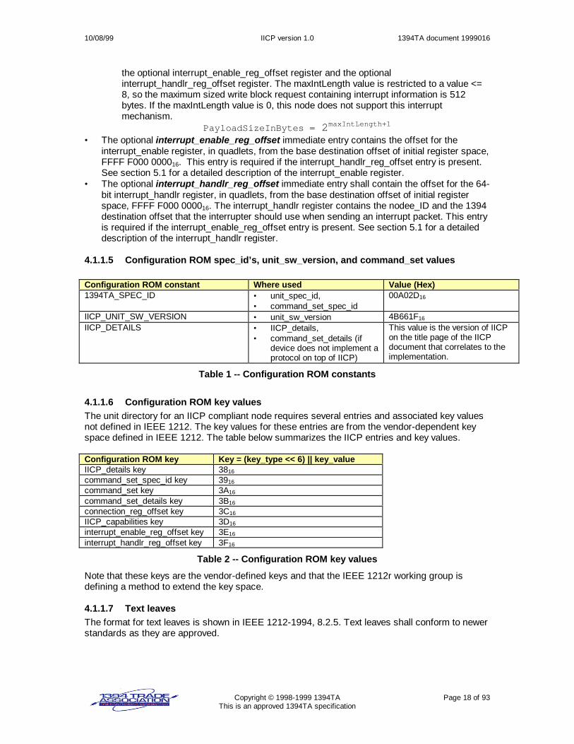
4.1.1.5 Configuration ROM spec_id’s, unit_sw_version, and command_set values
Configuration ROM constant Where used Value (Hex)1394TA_SPEC_ID • unit_spec_id,
• command_set_spec_id00A02D16
IICP_UNIT_SW_VERSION • unit_sw_version 4B661F16
IICP_DETAILS • IICP_details,• command_set_details (if
device does not implement aprotocol on top of IICP)
This value is the version of IICPon the title page of the IICPdocument that correlates to theimplementation.
Table 1 -- Configuration ROM constants
4.1.1.6 Configuration ROM key valuesThe unit directory for an IICP compliant node requires several entries and associated key valuesnot defined in IEEE 1212. The key values for these entries are from the vendor-dependent keyspace defined in IEEE 1212. The table below summarizes the IICP entries and key values.
Configuration ROM key Key = (key_type << 6) || key_valueIICP_details key 3816
command_set_spec_id key 3916
command_set key 3A16
command_set_details key 3B16
connection_reg_offset key 3C16
IICP_capabilities key 3D16
interrupt_enable_reg_offset key 3E16
interrupt_handlr_reg_offset key 3F16
Table 2 -- Configuration ROM key values
Note that these keys are the vendor-defined keys and that the IEEE 1212r working group isdefining a method to extend the key space.
4.1.1.7 Text leavesThe format for text leaves is shown in IEEE 1212-1994, 8.2.5. Text leaves shall conform to newerstandards as they are approved.

10/08/99 IICP version 1.0 1394TA document 1999016
Copyright © 1998-1999 1394TA Page 19 of 93This is an approved 1394TA specification
4.1.1.8 Instance directoriesInstance directories are optional. If instance directories are implemented in an IICP node, the II-WG should be consulted for keywords. The table below shows the keywords the II-WG hassubmitted at this time.
ACTUATOR AMPLIFIER ANALOG_INPUT ANALOG_OUTPUTANALYZER COUNTER DIGITAL_INPUT DIGITAL_OUPUTDMM FUNCTION_GENERATOR LINE_MONITOR LOGIC_ANALYZERMANOMETER OSCILLOSCOPE PATTERN_GENERATOR POWER_METERPOWER_SUPPLY RECORDER SENSOR SIGNAL_ANALYZERSPECTRUM_ANALYZER SWITCH THERMOMETER WAVEFORM_GENERATOR
4.1.2 Multi-protocol devicesSome IICP devices may need to implement more than one protocol. For example, a device mayimplement IICP and may also implement an Internet protocol 1394 stack and/or an SBP-2 1394stack.
To do this requires the configuration ROM to implement a unit directory specifically for eachprotocol that is supported.
4.1.3 Read operations on the configuration ROMAn implementation shall allow quadlet reads and block reads of the configuration ROM space.
4.1.4 Device aliases (nicknames) in the configuration ROMAt this time, the IEEE 1212r working group is defining a modifiable portion of the configurationROM to be used for a device alias or nickname. A device alias can provide a human-readabledescription of a device. This mechanism, when implemented in non-volatile memory, offersconvenient identification of devices and it is our recommendation that device aliases beimplemented when the appropriate standards are in place.

10/08/99 IICP version 1.0 1394TA document 1999016
Copyright © 1998-1999 1394TA Page 20 of 93This is an approved 1394TA specification
5. IICP 1394 memory-mapped I/OSome IICP implementations may support memory mapped I/O in addition to the memory mappedI/O required by the CSR Architecture, Serial Bus, and configuration ROM. The device providessome device-dependent memory that is mapped to 1394 space.
Memory mapped 1394 I/O means that the 48-bit destination offset in a 1394 packet is used todetermine the memory that is accessed on the memory mapped device. For example, a digital toanalog converter may define a 48-bit destination offset as the offset that contains the digital valueit will convert to an analog value. The application may issue a 1394 write quadlet request to writethe new digital value to be converted. The destination offset in the write-quadlet request packet isset by the application to be the understood (device-dependent) destination offset that the memorymapped device uses for new digital data.
5.1 Interrupt mechanism for IICP memory mapped devicesAn interrupt mechanism is defined for memory mapped IICP (not plug-capable) implementations.
The unit directory in the configuration ROM has a pair of optional entries:• An interrupt_enable_reg_offset entry.• An interrupt_handlr_reg_offset entry.
If a unit directory does not have both of these entries, then this interrupt mechanism is notsupported. If a unit directory has both of these entries and the configuration ROM unit directoryhas a non-zero valued maxIntLength field, this interrupt mechanism is supported.
5.1.1 interrupt_enable registerThe format for the interrupt_enable register is shown below.
Figure 11 -- interrupt_enable register
• The reserved field shall be reserved for future use.• The en-bit (enable) enables the sending of device-dependent interrupt information to the
destination_offset specified in the interrupt_handlr register. The device receiving the interruptinformation must update this register and re-enable the bit (en = 1) to receive more interrupts.Updating the interrupt_enable register shall be done with a write quadlet request.
The initial value of the interrupt_enable register shall be 0.
After a bus reset, the interrupt_enable register en-bit shall be cleared. A device making use of thismechanism will need to update this register and set the en-bit to 1.
A read of the interrupt_enable register shall return the current register contents.
A write of this register results in an unconditional update of the contents of the register.
5.1.2 interrupt_handlr registerThe format for the interrupt_handlr register is shown below.
Figure 12 -- interrupt_handlr register
reserved en
node_ID
destination_offset

10/08/99 IICP version 1.0 1394TA document 1999016
Copyright © 1998-1999 1394TA Page 21 of 93This is an approved 1394TA specification
• The node_ID is as defined in 1394-1995, section 6.2.4.2.1. Any node utilizing thismechanism shall be responsible for updating this field after a bus reset since the node_IDmay change.
• The destination_offset is used as the destination offset for the 1394 write request whensending the interrupt information to the node specified in node_ID.
The initial value of the interrupt_handlr register shall be 0.
After a bus reset, the content of the interrupt_handlr register remains unchanged. A devicemaking use of this register may need to update the node_ID field after a bus reset.
A read of the interrupt_handlr register shall return the current register contents.
A write of this register results in an unconditional update of the contents of the register.
When an interrupt condition occurs, and the en-bit in the interrupt_enable register has beenprogrammed to 1, the interrupting device sends device-dependent interrupt information to thedestination address specified in the “interrupt_handlr register”. The size of the data payload shallnot be larger than that specified in the maxIntLength field in the configuration ROM“IICP_Capabilities” entry. The content of the interrupt information is beyond the scope of thisdocument.
The interrupt-handling device processes the interrupt and when done, re-enables the interruptingdevice to send another interrupt by writing to the interrupt_enable register. To re-enable, the en-bit shall be one-valued. Devices shall not send any more interrupts until after a one-value iswritten to the en-bit.
An implementation is not required to clear the en-bit. If an implementation does clear the en-bit, itis recommended that the en-bit be cleared prior to sending the interrupt.
5.2 1394 memory mapped only IICP device limitationsDevices equipped with only 1394 memory mapped I/O may lack certain attributes that may bekey in some 1394 applications.• Memory mapped devices may not be robust in multi-controller or multi-threaded
environments.• Memory mapped devices provide only device-dependent I/O. The memory mapped locations
for I/O must be built into the software drivers.• Memory mapped devices provide no defined data flow control mechanisms.• There is no defined control path. If the data path becomes blocked for some reason, there is
no defined mechanism for recovery.
These limitations provide motivation for the next chapter, “IICP asynchronous plug connections”.

10/08/99 IICP version 1.0 1394TA document 1999016
Copyright © 1998-1999 1394TA Page 22 of 93This is an approved 1394TA specification
6. IICP asynchronous plug connectionsThis chapter explains the creation, use, and maintenance of a communication path for thetransfer of data frames and control frames from one IICP device to another IICP device.
The figure below shows a typical IICP connection between a computer and an instrument.
Figure 13 -- Typical IICP connection
6.1 Introduction to IICP connection plugsA plug contains two ports: a data port and a control port.
Each port allows duplex communications with the connected node.
Using the data port, data bytes may be transferred from the computer (acting as a producer) tothe instrument (acting as a consumer). Data bytes may also be transferred from the instrument(acting as a producer) to the computer (acting as a consumer).
Using the control port, control bytes may be transferred from the computer (acting as a producerof control bytes) to the instrument (acting as a control byte consumer). Control bytes may also betransferred from the instrument (acting as a producer of control bytes) to the computer (acting asa control byte consumer). Control bytes may be control messages, interrupts, triggers, and/orcommands. The actual use of the data port and control ports is determined by higher-levelprotocols.
The control port allows the data path to remain a pure data path. This may, in some higher levelprotocols, free a device from parsing received packets. The control port also provides the meansto communicate a potential remedy in case the data communication path hangs for some reason.
Although the IICP plug architecture allows duplex communication, simplex operation results if oneof the ports does not produce frames. If an IICP connection is simplex and not duplex, resourcesare scaled back appropriately.
6.1.1 IICP framesData bytes and control bytes are transferred with one or more 1394 write operations. Data andcontrol bytes are transferred in a logical group of bytes called a frame.
IICP plugs provide two methods, or modes, of transferring frames. small frame transfer mode isused when a frame is 512 bytes or less and fits in one 1394 write transaction. large frame
Computer
Connectionregister
DataPort
ControlPort
Plug
p
c
p
c
DataPort
ControlPort
p
c
p
c
Plug
Connectionregister
InstrumentData Frames
ControlFrames
p = producerc = consumer
Connection requests and responses

10/08/99 IICP version 1.0 1394TA document 1999016
Copyright © 1998-1999 1394TA Page 23 of 93This is an approved 1394TA specification
transfer mode shall be used when a frame requires more than one 1394 write transaction or whena consumer disallows small frame transfer mode.
Some producers, such as a simple sensor or analog-to-digital converter may not have logicalframes. Such producers are free to produce conveniently sized or optimally sized data frames.These data frames may be sized for maximum transfer efficiency. A frame should not be toosmall, because if transferred as a large frame, there are three 1394 transactions per frame. Iftransferred as a small frame, 1394 bus bandwidth is best utilized if the frame size is 512 bytes.Frames are not required to be of similar size.
Sections 6.4 and 6.5 provide an introduction to how large frame transfers and small frametransfers are accomplished. Actual producer and consumer state machine details are given later,in sections 6.20 and 6.21.

10/08/99 IICP version 1.0 1394TA document 1999016
Copyright © 1998-1999 1394TA Page 24 of 93This is an approved 1394TA specification
6.1.2 Plug architectureA plug is a data structure consisting of “private” memory and “public” memory. The public memoryis mapped to 1394 space and the connected node may update this mapped memory. The plugdata structure is illustrated in the figure below.
Figure 14 -- IICP plug contents
The plug private memory contains information needed in setting up and maintaining theconnection. This includes plug state information and information about the connected node. It iscalled private because this information is not mapped into 1394 space.
PlugState information may include (but is not limited to):• Producer state machine “state”.• Consumer state machine “state”.
PlugDestinationOffset + 496
PlugDestinationOffset + 272
PlugDestinationOffset + 264
PlugDestinationOffset + 260
PlugDestinationOffset + 504
512 Byte aligned(PlugDestinationOffset % 512) == 0)
ControlPort
(public)
PlugDestinationOffset + 508
PlugDestinationOffset + 0
PlugDestinationOffset + 4
PlugDestinationOffset + 16
PlugDestinationOffset + 8
PlugDestinationOffset + 20
PlugDestinationOffset + 240
PlugDestinationOffset + 256
PlugDestinationOffset + 248
DataPort
(public)
PlugDestinationOffset + 252
PlugDestinationOffset + 24
PlugDestinationOffset + 32
reserved
SmallFrameConsumer
ProducerLimits
LargeFramePageTableElement[0]
LargeFramePageTableElement[1]
...
LargeFramePageTableElement[27]
SmallFramePageTableElement
SmallFrameProducer
LargeFrameProducer
LargeFrameConsumer
PlugState
Connected Node InformationNot mapped to 1394 space Plug private
memory
PlugDestinationOffset + 276
PlugDestinationOffset + 280
PlugDestinationOffset + 288
reserved
SmallFrameConsumer
ProducerLimits
LargeFramePageTableElement[0]
LargeFramePageTableElement[1]
...
LargeFramePageTableElement[27]
SmallFramePageTableElement
SmallFrameProducer
LargeFrameProducer
LargeFrameConsumer

10/08/99 IICP version 1.0 1394TA document 1999016
Copyright © 1998-1999 1394TA Page 25 of 93This is an approved 1394TA specification
The “Connected Node” information consists of whatever information is necessary to communicateto the connected node. This information may include (but is not limited to) the following:• The 64-bit 1394 destination address (see IEEE1394-1995, 6.2.4.2) for the plug data port on
the connected node.• The attributes about the connected node plug communicated during the connection
sequence. See section 6.11.
The plug public memory is memory mapped into contiguous 1394 space. This memory contains aProducerLimits register, a SmallFramePageTableElement register, a SmallFrameProducerregister, a LargeFrameProducer register, a LargeFramePageTableElement[] register array, aSmallFrameConsumer register and a LargeFrameConsumer register.
The plug public memory shall be 512 bytes, evenly distributed to the data port and control port.
IICP implementations shall place plug public memory in 1394 space such that write transactionsto public plug registers result in an interrupt to the controlling software.
Each plug shall be created with the resources shown. Higher level protocols, implemented on topof IICP, may decide how the data port and control ports are utilized.
6.2 Plug register detailsThis section describes the definitions of bits in each of the plug registers. The reader should skimthis section first, then refer back to it when necessary.
6.2.1 ProducerLimits registerThe ProducerLimits register is a 32-bit register that a consumer updates. The ProducerLimitsregister contains a value that limits the size of individual write requests sent by a producer. Theformat of the ProducerLimits register is shown below.
Figure 15 -- ProducerLimits register
• The 4-bit maxLoad field specifies the data-payload size limitations for individual, single 1394segment-buffer writes, as specified in Equation 1. The amount of data in the write requestcannot exceed the payloadSizeInBytes value. The maxLoad value shall be equal to or largerthan 1, and is allowed to exceed the size of the node’s ROM-specified max_rec value, asdefined by the Serial Bus in IEEE 1394-1995, section 8.3.2.5.4.
Equation 1: payloadSizeInBytes = 2(maxLoad+1)
MaxLoad PayloadSizeInBytes1 42 8… …10 2048 (400 Mbps maximum value)…
Table 3 -- maxLoad-payload values
The initial value of the ProducerLimits register shall be all zeros.
After a bus reset, the values remain unchanged.
A read of this register returns the current register contents.
maxLoadreserved

10/08/99 IICP version 1.0 1394TA document 1999016
Copyright © 1998-1999 1394TA Page 26 of 93This is an approved 1394TA specification
A write of this register results in an update of the contents of the register. A consumer shall onlyupdate this register when the producer is expecting both a SmallFrameProducer andLargeFrameProducer update.
6.2.2 SmallFramePageTableElement registerThe SmallFramePageTableElement register uses the PageTableElement format shown below.There is a 16-bit length and a 48-bit pointer to a consumer segment buffer. A consumer writes theSmallFramePageTableElement register so that the destination_offset is mapped to non-physicalDMA 1394 space on the consumer. An interrupt will occur when a producer writes to the 1394space specified in the SmallFramePageTableElement.
Figure 16 – PageTableElement register
• The length specifies the number of bytes a producer may write to the consumer segmentbuffer, which begins at the specified destination_offset. A value of 0 specifies 64 KBytes.
• The destination_offset is the 48-bit destination offset marking the start of the consumerbuffer.
The initial value of the SmallFramePageTableElement register shall be all zeros.
After a bus reset, the values remain unchanged.
A read of this register returns the current register contents.
A write of this register results in an update of the contents of the register. A consumer is allowedto write this register prior to, or concurrently with, updating the SmallFrameProducer register.
6.2.3 SmallFrameProducer registerThe SmallFrameProducer register is a 32-bit register that a consumer updates when ready toreceive more small frames. The format of the SmallFrameProducer register is shown below.
Figure 17 -- SmallFrameProducer register
• A one-valued run bit enables small frame transfers and shall be cleared when a bus resetoccurs. A zero-valued run bit shall inhibit transfer of small frames. The intent is to delay smallframe transfers until the consumer’s state has been properly initialized.
• The sc-bit is the segment count bit. The consumer, when updating the SmallFrameProducerregister, shall toggle the value in the sc-bit. The first consumer update of theSmallFrameProducer register shall set the sc-bit to one, the second consumer update of theSmallFrameProducer register shall set the sc-bit to zero, and so on.
• The 16-bit maxSmallFrameCount field specifies the maximum number of small frames thata producer can send before updating the consumer SmallFrameConsumer register. Thisserves to limit the size of data structures the consumer may require for processing smallframes. If the maxSmallFrameCount is 0, the producer shall send all frames using the largeframe transfer mode and the producer shall ignore the SmallFramePageTableElementregister.
The initial value of the SmallFrameProducer register shall be all zeros.
After a bus reset, the run bit is set to 0. The other bits are not changed.
length
destination_offset
reserved sc maxSmallFrameCountrun reserved

10/08/99 IICP version 1.0 1394TA document 1999016
Copyright © 1998-1999 1394TA Page 27 of 93This is an approved 1394TA specification
A read of this register returns the current register contents.
A write of this register results in an update of the contents of the register, provided the sc-bit is adifferent value. The consumer is allowed to update the producer SmallFrameProducer register toinitially start small frame transfers, after a bus reset, and after the producer has written to theconsumer SmallFrameConsumer register and the consumer is ready for more small frames.
6.2.4 LargeFrameProducer registerThe LargeFrameProducer register is a 32-bit register that a consumer updates. The consumerupdates the LargeFrameProducer register when the consumer is ready to receive large framecontent. The format of the register is shown below.
Figure 18 -- LargeFrameProducer register
• A one-valued run bit enables the operation of the producer and shall be cleared when a busreset occurs. A zero-valued run bit shall inhibit large frame transfers.
• The sc-bit is the segment count bit. The consumer, when updating the LargeFrameProducerregister, shall toggle the value in the sc-bit. The first consumer update of theLargeFrameProducer register shall set the sc-bit to one, the second consumer update of theLargeFrameProducer register shall set the sc-bit to zero, and so on.
• The 21-bit count specifies the total number of bytes in the consumer segment bufferdescribed in the LargeFramePageTableElement[] registers for receiving large frame content.The consumer segment buffer space is described beginning with PageTableElement[0].
The initial value of the LargeFrameProducer register shall be all zeros.
After a bus reset, the run bit is set to 0. The other bits are not changed.
A read of this register returns the current register contents.
A write of this register results in an update of the contents of the register, provided the sc-bit is adifferent value. The consumer is allowed to update the LargeFrameProducer register to initiallystart large frame transfers, after a bus reset, and after the producer has written to the consumerLargeFrameConsumer register and the consumer is ready for more data.
6.2.5 LargeFramePageTableElement registersThe LargeFramePageTableElement[] array consists of PageTableElement registers as shown inFigure 16. The LargeFramePageTableElement[] registers point to consumer segment buffersmapped to 1394 space on the connected node.
The multiple LargeFramePageTableElement[] registers allow a consumer to program a producerwith a scatter/gather list describing the location of a consumer segment buffer in possibly non-contiguous 1394 space.
Use of scatter/gather may increase efficiencies by limiting the number of times 1394 data getscopied. For example, OHCI 1394 link implementations allow physical memory to be directlymapped to 1394 space. It is normal (at least on the computer side), for an application buffer, oruser-space buffer, to reside in multiple physical memory locations. If a scatter/gather list iscommunicated to the producer, the producer can write 1394 data directly to the user-spacebuffer, filling up different physical pages in memory.
countreserved sc reservedrun

10/08/99 IICP version 1.0 1394TA document 1999016
Copyright © 1998-1999 1394TA Page 28 of 93This is an approved 1394TA specification
To simplify producer implementations, the consumer shall program the length field of all but thefirst and the last relevant LargeFramePageTableElement registers with a length = 2N. N shall bethe same value for all but the first and last relevant LargeFramePageTableElement[] registers.
The initial value of the LargeFramePageTableElement[] registers shall be all zeros.
After a bus reset, the values remain unchanged.
A read of any LargeFramePageTableElement[] registers returns the current contents.
A write of LargeFramePageTableElement[] registers results in an update of the contents of theregisters. A consumer is allowed to write this register immediately prior to, or concurrently with,updating the LargeFrameProducer register.
6.2.6 SmallFrameConsumer registerThe SmallFrameConsumer register is a 32-bit register that a producer updates when the smallframe buffer space has been filled such that the next small frame would not fit in the remainingspace or the producer has sent the maximum number of small frames. The format is shownbelow.
Figure 19 – SmallFrameConsumer register
• The producer shall write a one-valued (SFB_FULL) mode-bit when the small frame bufferspace is exhausted or the producer has sent the maximum number of small frames.
• The sc-bit is the segment count bit. The producer, when updating the consumer’sSmallFrameConsumer register, shall set this bit to the most recent sc-bit value that theconsumer wrote into the producer’s SmallFrameProducer sc-bit. This bit distinctively labelsthe sequential handshakes between the consumer and the producer.
The initial value of the SmallFrameConsumer register shall be all zeros.
After a bus reset, the values remain unchanged.
A read of this register returns the last successfully written data.
A write of this register results in an update of the contents of the register provided the sc-bit is thesame value the consumer wrote to the SmallFrameProducer register.
6.2.7 LargeFrameConsumer registerThe LargeFrameConsumer register is a 32-bit register that a producer updates. Examples ofwhen the producer updates this register include:1) The producer has finished the transfer of a large frame.2) There is no space left in the buffer space described by the LargeFramePageTableElement[]
registers.
Figure 20 -- LargeFrameConsumer register
• The 2-bit mode field provides frame-completion information, as specified in the table below.
reserved
mode
sc reserved
countreserved mode sc reserved

10/08/99 IICP version 1.0 1394TA document 1999016
Copyright © 1998-1999 1394TA Page 29 of 93This is an approved 1394TA specification
Mode Name Descriptionf0 FREE Initial (never written) state. Shall never be written by the producer.1 MORE Indication for leading (not end of frame, last) content.2 LAST Indication for last, end of frame content.3 TRUNC Indication for truncated frame content, end of frame
Table 4 -- LargeFrameConsumer.mode definition
• The sc-bit is the segment count bit. The producer, when updating the consumer’sLargeFrameConsumer register, shall set this bit to the most recent sc-bit value that theconsumer wrote into the producer’s LargeFrameProducer.sc bit. This bit distinctively labelsthe sequential handshakes between the consumer and the producer.
• The 21-bit count value identifies how many bytes have been written by the producer to thebuffers identified in the LargeFramePageTableElement[] registers since the lastLargeFrameProducer update. Note that this value may be less than the amount of bytes theconsumer allowed the producer to send.
The initial value of the LargeFrameConsumer register shall be all zeros.
After a bus reset, the values remain unchanged.
A read of this register returns the last successfully written data.
A write of this register results in an update of the contents of the register provided the sc-bit is thesame value the consumer wrote to the LargeFrameProducer register.
6.3 1394 operations allowed on plug registersPlug registers shall be updated with write block or write quadlet transactions. The destinationoffset in the 1394 write request shall be quadlet aligned. The length of the write transaction shallbe a multiple of 4.
IEEE 1394 lock request transactions are not permitted on plug registers.
6.3.1 Efficient updating of plug registersFor efficiency, a consumer is allowed to update multiple port registers with one write blocktransaction. However, registers may only be updated at the proper times.
If a consumer updates producer port registers with more than one write operation, the consumerupdate shall affect the LargeFrameProducer only once, and the write affecting theLargeFrameProducer shall occur after, or concurrent with, the writing of theLargeFramePageTableElement[] array. The LargeFramePageTableElement[] array registers shallnot be changed after a LargeFrameProducer update until the producer updates theLargeFrameConsumer register.
Similarly, the consumer update of the producer port shall affect the SmallFrameProducer onlyonce, and the write affecting the SmallFrameProducer shall occur after, or concurrent with, thewriting of the SmallFramePageTableElement. The SmallFramePageTableElement register shallnot be changed after a SmallFrameProducer update until the producer updates theSmallFrameConsumer register.
6.4 Large frame transfersFrames that do not fit the requirements for small frames are transferred using the large frametransfer mode. In this mode, LargeFrameConsumer and LargeFrameProducer registers areupdated after each frame transfer.

10/08/99 IICP version 1.0 1394TA document 1999016
Copyright © 1998-1999 1394TA Page 30 of 93This is an approved 1394TA specification
The sequence below illustrates a producer sending large frames to a consumer. The sequenceassumes the ProducerLimits register has been previously updated. Refer to the producer andconsumer state machines in sections 6.20 and 6.21for more detail.
1. The consumer, when ready to receive more frame contents:a) Sends a write block transaction to update the producer LargeFrameProducer and
LargeFramePageTableElement[] registers as necessary. After the LargeFrameProducerregister is updated, the consumer is not permitted to change theLargeFramePageTableElement[] registers until after a LargeFrameConsumer update.
2. The producer:a) Waits for a request from an application layer to transfer frame content.b) Waits for a LargeFrameProducer update if necessary. This is necessary if the
LargeFrameProducer register has never been updated or the producer has written to theconsumer LargeFrameConsumer register.
c) Writes the frame content to the consumer segment buffer described byLargeFramePageTableElement[0]. This may consist of several 1394 packets. If multipleLargeFramePageTableElement[] registers have been set up, the producer sequencesthrough PageTableElement[0], PageTableElement[1], and so on.
d) Updates the consumer’s LargeFrameConsumer register. This lets the consumer knowhow much data the producer sent.
3. The consumer:a) Processes the data.
Repeat steps 1a through 3a.
The table below shows the general flow for large frame transfers.
Producer Consumerç Update the LargeFrameProducer and
LargeFramePageTableElement[] registers.Send data. May be multiple write block requests. èUpdate the consumer’s LargeFrameConsumerregister.
è
Read how much data the producer sent.Process the data.
ç Update the LargeFrameProducer andLargeFramePageTableElement[] registers.
Send data. May be multiple write block requests. èUpdate the consumer’s LargeFrameConsumerregister.
è
… … …
Figure 21 – Large frame transfers
6.4.1 Sequential and non-sequential writes for large frame transfersNormally, a producer will fill the consumer buffer space sequentially. However, some consumersmay not care about the ordering of writes from the producer. This is determined during theconnection sequence.
If a consumer requires sequential writes, the initial write request is sent with a destination offsetequal to the LargeFramePageTableElement[0] destination_offset value. Subsequent packets aresent to a destination offset increasingly offset from the first destination_offset value. Theincreasing offset value corresponds to the amount of data sent. These writes continue until thecomplete frame has been sent or the consumer buffer space specified in theLargeFramePageTableElement[0] is full. If the buffer specified inLargeFramePageTableElement[0] is full, and multiple LargeFramePageTableElement[] registers

10/08/99 IICP version 1.0 1394TA document 1999016
Copyright © 1998-1999 1394TA Page 31 of 93This is an approved 1394TA specification
have been set up, and there is still more frame content to be sent, writes continue in the sameway, beginning with a destination offset equal to the LargeFramePageTableElement[1]destination_offset value.
If the consumer does not require sequential writes during large frame transfers, the producer isfree to write the data with an unspecified ordering for the destination offsets, eventually filling upthe consumer segment buffers. The result for both sequential and non-sequential writes is thesame – a filled or partially filled consumer buffer space that begins with the consumer bufferspace specified in LargeFramePageTableElement[0].
6.5 Small frame transfersA small frame is a frame that may be sent in a single write transaction with payload size <= 512bytes.
There are many situations where a computer may repeatedly send small frames to a device. Anexample is when a computer is sending some kind of query to an instrument to get measurementresults.
For small frames, there is no need for flow control updates for every frame. Instead, the flowcontrol updates only need occur when the next small frame does not fit completely into the smallframe space. This allows frame transfers using just one 1394 transaction per frame. This is moreefficient than the three 1394 transactions used in large frame mode, whereLargeFrameConsumer and LargeFrameProducer registers are updated for each frame. Smallframe transfers rely on 1394 drivers sending the small frame in one 1394 transaction.
The sequence below illustrates a producer sending small frames to a consumer. The sequenceassumes the ProducerLimits register has been previously updated. Refer to the producer andconsumer state machines in sections 6.20 and 6.21for more detail.
1. The consumer, when ready for more small frames:a) Updates the producer SmallFramePageTableElement and SmallFrameProducer register
as necessary. After the SmallFrameProducer register is updated, the consumer is notpermitted to change the SmallFramePageTableElement register until after aSmallFrameConsumer update.
2. The producer:a) Waits for a request from an application layer to transfer a small frame.b) Waits for a SmallFrameProducer register update if necessary. This is necessary if the
SmallFrameProducer register has never been updated or the producer has written to theconsumer SmallFrameConsumer register.
c) Checks that the frame may be sent as a small frame.d) Writes the frame to the small frame space specified in the
SmallFramePageTableElement register, offset by an amount equal to the amount of datatransferred to the small frame space since the last SmallFrameProducer register update.
3. The consumer:a) Receives the small frame and forwards it to the application.
Steps 2 and 3 are repeated until the next small frame will not fit completely into the remainingsmall frame space or the producer has sent the maximum allowed number of small frames. Whenthat happens, the producer shall not send any part of the small frame. The producer shall insteadupdate the consumer’s SmallFrameConsumer register, indicating the remaining small framespace is insufficient size. The consumer then updates the producer’s SmallFrameProducerregister when ready for more data.
The table below shows the general flow for small frame transfers.

10/08/99 IICP version 1.0 1394TA document 1999016
Copyright © 1998-1999 1394TA Page 32 of 93This is an approved 1394TA specification
Producer Consumerç Update the SmallFramePageTableElement and
SmallFrameProducer register as necessary.Receive transfer request. Perform tests. Sendthe small frame, using one 1394 transaction.
è
Interrupt occurs when frame received. Sendframe to application.
… … …Receive transfer request. Perform tests and seethe small frame will not fit into the small framespace. Update the SmallFrameConsumerregister.
è
ç Process the SmallFrameConsumer update.Update the SmallFramePageTableElement andSmallFrameProducer register as necessary.
Receive transfer request. Perform tests. Sendthe small frame, using one 1394 transaction.
è
… … …
Figure 22 -- Small frame transfers
The size of small-frames is indicated by the 1394 header and is not replicated in the payloadportion of the packet.
For this reason, implementations are expected to have hardware/software mechanisms forassociating the write-transaction payload size (from the write request packet header) with thedata payload.
After receiving a small frame, a consumer shall not hold off subsequent small frames viaack_busy’s or any other mechanism while the small frame is being processed. A consumer isobligated to let the producer send maxSmallFrameCount small frames, so long as the smallframe consumer segment buffer is not filled.
6.6 Mixing of large frame mode and small frame transfer modeOnce a producer has started a large frame transfer, small frame transfers are not permitted untilthe LargeFrameConsumer register has been updated with a mode value indicating the end of alarge frame. Once the LargeFrameConsumer register has been updated with a mode valueindicating the end of a large frame, small frame transfers may resume, beginning at an offsetequal to the total size of all of the small frames sent before the large frame transfer commenced.
A producer is allowed to send a small frame and then begin a large frame transfer withoutupdating the SmallFrameConsumer register.
A producer is allowed to send frames that fit the criteria for small frames using the large frametransfer mode.

10/08/99 IICP version 1.0 1394TA document 1999016
Copyright © 1998-1999 1394TA Page 33 of 93This is an approved 1394TA specification
6.7 Consumer segment buffersA producer writes frame contents to consumer segment buffers on the connected node. Aconsumer may utilize one or more consumer segment buffers for receiving large frames. Aconsumer may utilize one or more consumer segment buffers for receiving small frames. The useof multiple segment buffers allows overlap – the consumer may process a filled segment bufferwhile the producer is filling up an available segment buffer. The figure below illustrates asuggested strategy of using 2 large frame consumer segment buffers and 1 small frameconsumer segment buffer.
Figure 23 -- Consumer segment buffers
6.8 Plug schematicsFor clarity, the schematic view of 2 plugs connected together to form a dual-duplexcommunication path is shown below. “p” is short for producer, “c” is short for consumer. Note thatalthough 2 receive segment buffers are shown in the data paths, only 1 receive segment buffer isrequired.
Figure 24 -- IICP plug schematic
Node B
plug
c
p
c
pControlframes
Node A
plug
c
p
c
p
data
Receivesegmentbuffers
ReceiveSegment
buffers
Producer
large frame PageTableElement[]
small frame PageTableElement
Consumer
for largeframes
#2,4,6,...
for largeframes
#1,3,5,...
page 0
page 1
page N...
largeframe
segmentbuffer 1
page 0
page 1
page N...
largeframe
segmentbuffer 2
small framespace

10/08/99 IICP version 1.0 1394TA document 1999016
Copyright © 1998-1999 1394TA Page 34 of 93This is an approved 1394TA specification
This may also be drawn as:
Figure 25 -- Shorthand IICP plug schematic
6.9 Multiple devicesFor a node to communicate to more than one other node, separate and distinct plugs need to becreated for each attached node. In the figure below, there would be N plugs on the computer forthe N devices.
Figure 26 -- Multiple instrument connections
6.10 Connection variationsIn all cases, a plug is used for data and control communications between two nodes. A plug is notexpandable.
There is no limit in this specification concerning the number of plugs a device may create.
An IICP device that is plug-capable may also implement device-dependent 1394 memorymapped capabilities.
…
NodeA
NodeB
IICP
Computer Instrument 1IICP
Instrument 2IICP
Instrument NIICP

10/08/99 IICP version 1.0 1394TA document 1999016
Copyright © 1998-1999 1394TA Page 35 of 93This is an approved 1394TA specification
6.11 Creating an IICP connectionAn IICP connection manager establishes an IICP connection by sending connection requestpackets to device1 and device2. In the figure below, Device1 and Device2 are attached nodes onthe bus, distinct from the node acting as the IICP connection manager.
Figure 27 -- Connection manager with 2 independent devices
An IICP device may be integrated into the connection manager, as shown below. In this case,connection requests sent to Device1 and connection responses received from Device1 are not1394 packets but rather internal software actions. Device1 is both a connection manager and aconnection client.
Figure 28 -- Connection manager with 1 independent device
The table below shows the general flow in creating a connection between device1 and device2.See section 6.18 for the connection manager state machine and section 6.19 for the connectionclient state machine for complete details.
Device1(Connection Client)
ConnectionRegister Connection Requests and responses
Connection Manager
ConnectionRegister
IICPPlug
Device2(Connection Client)
ConnectionRegister
Plug
Device2(Connection Client)
ConnectionRegister
Device1(ConnectionManager +
Connection Client)
ConnectionRegister
Plug IICP
Connection Requests and responses
Plug

10/08/99 IICP version 1.0 1394TA document 1999016
Copyright © 1998-1999 1394TA Page 36 of 93This is an approved 1394TA specification
Step Device1 Connection Manager Device21 Lock connection register.2 ç Lock device1 connection
register.3 Lock device2 connection
register.è
4 ç Send connection requestpacket (CREQ1) to device1.
5 Create plug. Send connectionresponse packet (CRESP).
è
6 Send connection requestpacket (CREQ1) to device2.
è
7 ç Create plug. Send connectionresponse packet. (CRESP1).
8 ç Send connection requestpacket (CREQ2) to device1.
9 Allocate segment buffers.Send connection responsepacket (STATUS).
è
10 Send connection requestpacket (CREQ2) to device2.
è
11 ç Allocate segment buffers.Send connection responsepacket (STATUS).
12 Unlock connection register.13 ç Unlock device1 connection
register.14 Device1 may now update
plug registers on device2.Unlock device2 connectionregister.
è
15 Device2 may now updateplug registers on device1.
Figure 29 -- Establishing an IICP connection
6.11.1 Connection creation sequenceThe details for each of the steps in the table are given below.
6.11.1.1 Connection manager locks its connection lock registerThe connection manager shall first lock its connection lock register. Locking of its connection lockregister is done with an atomic test and set operation. The need to specify “atomic” is to make thepoint that the connection manager must be able to test the state of its own lock register and thenset the lock, without worrying about an external lock request from another device interfering.
6.11.1.2 Connection manager locks device1 connection lock registerThe connection manager next locks the device1 connection register. Locking of all non-connection manager connection registers is accomplished by using a 1394 compare and swaplock transaction. The connection manager executes a 1394 compare & swap lock operation onthe device connection lock register. Refer to IEEE1394-1995 sections 3.5.2, 6.2.2.3.2, 6.2.2.3.4,6.2.4.9, and 7.3.4.3 for more details on compare and swap lock requests and responses. A lockrequest packet is shown below.

10/08/99 IICP version 1.0 1394TA document 1999016
Copyright © 1998-1999 1394TA Page 37 of 93This is an approved 1394TA specification
Figure 30 -- Connection register lock request packet
• destination_offset shall be set to the location of the connection register, as specified in theconfiguration ROM.
• arg_value shall be 64-bits and shall be all 0’s when attempting to lock the connectionregister, since an unlocked connection register is by definition, 0-valued.
• data_value shall be 64-bits and shall be the unique_ID of the device attempting to lock theconnection register.
A compare_swap lock request performs the following equivalent “C” code:
if ( old_value == arg_value ) new_value = data_value;return old_value; // in the lock response packet
The device returns a lock response. If the lock response indicates old_value = 0, the lock wassuccessful. If the lock response indicates non-zero, the lock was unsuccessful. A lock responsepacket is shown below.
Figure 31 -- Connection register lock response packet
• rcode is the appropriate response code.• old_value is the original value of the connection lock register. If 0, the connection register
has been successfully locked.
destination_ID tl rt tcode=9 pri
source_ID
destination_offset
data_length=16 extended_tcode=2
arg_value (high)
arg_value (low)
header_CRC
data_CRC
data_value (high)
data_value (low)
destination_ID tl rt tcode=0xb pri
source_ID
reserved
data_length=8 extended_tcode=2
old_value (high)
old_value (low)
header_CRC
data_CRC
rcode reserved

10/08/99 IICP version 1.0 1394TA document 1999016
Copyright © 1998-1999 1394TA Page 38 of 93This is an approved 1394TA specification
6.11.1.3 Connection manager locks device2 connection registerThe connection manager next locks the device2 connection lock register. This is again done witha compare and swap lock request operation as described in 6.11.1.2.
If successful at locking the connection manager connection lock register and all other necessarydevice connection lock registers, the connection manager temporarily “owns” the connectionservices of all the devices it has locked. If unsuccessful, the connection manager shall unlock allthe connection lock registers it was successful in locking, then wait an implementation dependentperiod of time before retrying.
The connection manager is allowed to lock the connection registers for only a single operation.This is to prevent “hogging” of the connection registers by any one connection manager.
Connection clients maintain locks for time = CCLI_LOCK_TIMEOUT. See section 6.17 for thevalue. If the connection manager has not unlocked a connection register inCCLI_LOCK_TIMEOUT, the connection client shall assume some anomalous event occurred andshall unlock its own connection lock register. Any resources allocated due to received connectionrequests may and should be freed. If the CCLI_LOCK_TIMEOUT does occur, any furthertransactions (except a valid lock request) to the connection register shall fail. The device shallsend a response packet as shown in Figure 35, with a status indication ofCRS_REG_NOT_LOCKED.
If a bus reset occurs and a device connection register is locked, the connection register isimplicitly unlocked by the device. The connection manager then re-locks connection registers asnecessary.
6.11.1.4 Connection manager sends connection request packet (CREQ1) to device1The connection manager next sends a connection request packet (CREQ1) to device1. Thefigure below shows the connection request packet. The destination offset for this connectionrequest packet is the connection register location + 8 (bytes).
Figure 32 -- Connection request packet (CREQ1)
• connectPktId identifies the connection packet as a connection request. See Table 6 --ConnectPktId values in section 6.16.1.
• connectResponseOffset is the 48-bit destination offset for the connection response packet.• cmgr_unique_ID is the 64-bit unique_ID for the connection manager.• connectedNode_unique_ID is the 64-bit unique_ID for the other device being connected.
connectResponseOffset
command_set
node_ID
cmgr_unique_ID (low)
connectedNode_unique_ID (high)
connectedNode_unique_ID (low)
command_set_spec_id (low)
reserved connectPktID=CREQ1
cmgr_unique_ID (high)
command_set_spec_id (high)
connectionParameters (high)
connectionParameters (low)
command_set_detailsreserved

10/08/99 IICP version 1.0 1394TA document 1999016
Copyright © 1998-1999 1394TA Page 39 of 93This is an approved 1394TA specification
• node_ID is the 16-bit node_ID for the other device being connected.• command_set_spec_id specifies the organization that defines the following command_set
value.• command_set identifies the higher level protocol to be used for the connection. The
command_set value should match a unit directory command_set value in the configurationROM.
• command_set_details specifies the version of the command_set to be used.• connectionParameters is a 64-bit field that is defined by a higher level protocol.
6.11.1.5 Device1 sends response packet (CRESP)Device1 stores the information provided in the CREQ1 packet and formulates a connectionresponse packet to be sent to the connection manager. The destination offset for the responsepacket is the connectResponseOffset specified in the connection request packet. The format forthe response packet is shown below.
If connectRequestStatus is not equal to CRS_SUCCESS, the connection manager may then freeany resources associated with this connection. The connection manager shall unlock theconnection registers, and return an error to the application.
Figure 33 -- Connection response packet (CRESP)
• connectPktId identifies the connection packet as a response to a CREQ1 packet. See Table6 -- ConnectPktId values in section 6.16.1.
• connectRequestStatus is an indication of success or failure. A zero-value indicatessuccess. See section 6.16.2.
• The sfc-bit is one-valued if this node, acting as a producer, is capable of sending frames insmall frame transfer mode.
• The se-bit is an indication from this device of its tolerance for non-sequential writes. If se isone-valued, the connected node producer must write data sequentially to consumer segmentbuffers.
• plugDestinationOffset specifies the location in the device’s own 1394 space for the newlycreated plug.
• dataFrameSize is the maximum number of bytes in a data frame sent from this device. If all1’s, the size of data frames is unknown at this time. If all 0’s, there will be no data framesfrom this device. This field provides a hint for the connected device for sizing of the data pathconsumer segment buffers. See section 6.11.2.
• controlFrameSize is the maximum number of bytes in a control frame sent from this device.If all 1’s, the size of control frames is unknown at this time. If all 0’s, there will be no controlframes sent from this device. This field provides a hint for the connected device for sizing ofthe control path consumer segment buffers. See section 6.11.2.
6.11.1.6 Connection manager sends connection request packet (CREQ1) to device2The connection manager next sends a CREQ1 connection request packet to device2. The formatfor this packet was shown in Figure 32. In this case, node_ID and connectedNode_unique_IDpertain to device1. The destination offset is the connection register offset of device2 + 8 (bytes).
se
plugDestinationOffset
reserved connectPktID=CRESP connectRequestStatusreserved
reserved
dataFrameSize
controlFrameSize
reserved
reserved
sfc

10/08/99 IICP version 1.0 1394TA document 1999016
Copyright © 1998-1999 1394TA Page 40 of 93This is an approved 1394TA specification
6.11.1.7 Device2 sends response packet (CRESP)Device2 stores the information provided in the CREQ1 packet and formulates a connectionresponse packet to be sent to the connection manager. The destination offset for the responsepacket is the connectResponseOffset specified in the connection request packet. The format forthe response packet was shown previously in Figure 33.
6.11.1.8 Connection manager sends device2 information to device1 (CREQ2)The connection manager now sends device2 plug information to device1. The format for thispacket is shown below. The destination offset is the connection register of device1 + 8 (bytes).
Figure 34 -- Connection request packet (CREQ2)
• connectPktId identifies the packet as a final connection request. See Table 6 --ConnectPktId values in section 6.16.1.
• connectResponseOffset is the 1394 destination offset for the connection response packet.• The sfc-bit is one-valued if the connected node may utilize small frame transfer mode when
sending small frames. The sfc-bit is 0 if the connected node will never utilized small frametransfer mode.
• The se-bit is one-valued if the connected node requires frame contents to be writtensequentially.
• dataFrameSize is the number of bytes the connected producer will send in a data frame. Seesection 6.11.2.
• controlFrameSize is the total number of bytes the connected producer will send in a controlframe. See section 6.11.2.
6.11.1.9 Device1 sends response packet (STATUS)Device1 processes the connection request. It is recommended that device1 allocate segmentbuffer(s) for the data and control ports at this time. See section 6.11.2 below. Device1 thenformulates a connection response packet. The destination offset is the connectResponseOffsetspecified in the connection request packet. The format of the response packet is shown below.
Figure 35 -- Connection response packet (STATUS)
• connectPktId identifies the connection packet as a connection response. See Table 6 --ConnectPktId values in section 6.16.1.
• connectRequestStatus is an indication of success or failure. A zero-value indicatessuccess. See section 6.16.2.
If connectRequestStatus is not equal to CRS_SUCCESS, the connection manager shall unlockthe connection registers and return an error to the application.
connectResponseOffset
plugDestinationOffset
reserved connectPktID=CREQ2
sereserved
dataFrameSizereserved
controlFrameSizereserved
sfc
reserved connectPktID=STATUS connectRequestStatusreserved
10/08/99 IICP version 1.0 1394TA document 1999016
Copyright © 1998-1999 1394TA Page 41 of 93This is an approved 1394TA specification
6.11.1.10 Connection manager sends device1 information to device2 (CREQ2)The connection manager next sends a second connection request packet to device2, to conveyinformation about device1. The format for the connection request packet is shown in Figure 34(CREQ2). In this case, se, plugDestinationOffset, dataFrameSize, controlFrameSize areattributes of the device1 plug. The destination offset for the CREQ2 packet is the connectionregister offset of device2 + 8 (bytes).
6.11.1.11 Device2 processes request packet, sends connection responseDevice2 processes the connection request. Device2 formulates a connection response packet.The destination offset is the connectionResponseOffset specified in the request packet. Theformat of the response packet is shown in Figure 35 (STATUS).
If device2 unsuccessfully processes the request, device2 shall free any resources associated withthis plug and return a connectRequestStatus not equal to CRS_SUCCESS. The connectionmanager shall send a connection request packet (connectPktID = FREE) to device1, unlock theconnection registers, and return an error to the application.
6.11.1.12 Connection manager unlocks its connection registerThe connection manager next unlocks its connection lock register with a simple write operation,clearing the 64-bit connection lock register.
6.11.1.13 Connection manager unlocks device1 connection registerIf device1 is not the same device as the connection manager, unlocking of the device1connection lock register is accomplished by using a 1394 compare and swap lock transaction,similar to the compare and swap lock request issued to lock the device1 connection register, asshown in Figure 27. For unlocking, the lock request arg_value shall be the 64-bit unique_ID ofthe connection manager that acquired the lock, and the lock request data_value shall be 0.
When the device1 connection register is unlocked, device1 may update plug registers on theconnected node.
6.11.1.14 Connection manager unlocks device2 connection registerIf device2 is not the same device as the connection manager, unlocking of the device2connection lock register is accomplished by using a 1394 compare and swap lock transaction,similar to the compare and swap lock request issued to lock the device1 connection register, asshown in Figure 30. For unlocking, the lock request arg_value shall be the 64-bit unique_ID ofthe connection manager that acquired the lock, and the lock request data_value shall be 0.
When the device2 connection register is unlocked, device2 may update plug registers on theconnected node.
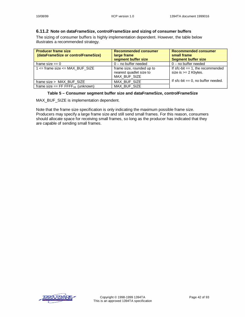
10/08/99 IICP version 1.0 1394TA document 1999016
Copyright © 1998-1999 1394TA Page 42 of 93This is an approved 1394TA specification
6.11.2 Note on dataFrameSize, controlFrameSize and sizing of consumer buffersThe sizing of consumer buffers is highly implementation dependent. However, the table belowillustrates a recommended strategy.
Producer frame size (dataFrameSize or controlFrameSize)
Recommended consumerlarge framesegment buffer size
Recommended consumersmall frameSegment buffer size
frame size == 0 0 – no buffer needed 0 – no buffer needed1 <= frame size <= MAX_BUF_SIZE frame size, rounded up to
nearest quadlet size toMAX_BUF_SIZE
frame size > MAX_BUF_SIZE MAX_BUF_SIZEframe size == FF FFFF16 (unknown) MAX_BUF_SIZE
If sfc-bit == 1, the recommendedsize is >= 2 Kbytes.
If sfc-bit == 0, no buffer needed.
Table 5 – Consumer segment buffer size and dataFrameSize, controlFrameSize
MAX_BUF_SIZE is implementation dependent.
Note that the frame size specification is only indicating the maximum possible frame size.Producers may specify a large frame size and still send small frames. For this reason, consumersshould allocate space for receiving small frames, so long as the producer has indicated that theyare capable of sending small frames.

10/08/99 IICP version 1.0 1394TA document 1999016
Copyright © 1998-1999 1394TA Page 43 of 93This is an approved 1394TA specification
6.12 Connection deactivationGenerally, a device sets all IICP plug producer and consumer state machines to the deactivatedstate after a 1394-bus reset. The reason is to prevent plug communications to an incorrectnode_ID. Node_ID’s may change after a bus reset.
No updates to the public plug 1394 space are allowed, and no frame transfer activity is alloweduntil the connection has been reactivated. If deactivated, and a plug access occurs, and theimplementation allows the specification of a response code, the response code shall beresp_conflict_err.
After a bus reset, all nodes with an IICP connection shall start a reactivation timer. Any furtherbus resets will cause the timer to be restarted. The connection manager that created the IICPconnection shall issue a reactivation request as soon as possible after a bus reset. If areactivation request is not received within time = REACT_TIMEOUT (see section 6.17 for value),a node experiencing resource shortages that can be remedied by freeing plug resources maydiscard and release plug resources associated with the timed out connection.
6.13 Connection reactivationWhen a 1394 connection plug is deactivated, a reactivation sequence is used to reactivate theconnection. It is recommended that connection managers reactivate connections beforeinstantiating any new connections.
The connection manager that issued the connection sequence to create the plug is responsiblefor issuing a reactivation sequence for the plug.
For each of the plugs a connection manager created, the connection manager shall go through areactivation sequence. The general flow is shown below. See section 6.18 for the connectionmanager state machine and section 6.19 for the connection client state machine for completedetails.Step Device1 Connection manager Device21 Lock connection register.2 ç Lock device1 connection
register.3 Lock device2 connection
register.è
4 ç Send reactivation requestpacket to device1 (REACT).
5 Process request. Sendconnection responsepacket (STATUS).
è
6 Send reactivation requestpacket to device2 (REACT).
è
7 ç Process request. Sendconnection responsepacket (STATUS).
8 Unlock connection register.9 ç Unlock device1 connection
register.10 May now communicate to
Device2.Unlock device2 connectionregister.
è
11 May now communicate toDevice1.
Figure 36 - Reactivation sequence

10/08/99 IICP version 1.0 1394TA document 1999016
Copyright © 1998-1999 1394TA Page 44 of 93This is an approved 1394TA specification
6.13.1 Reactivation sequenceThe details for each of the steps in the table are given below.
6.13.1.1 Connection manager locks its own connection registerThe connection manager shall first lock its own connection register as described in section6.11.1.1.
6.13.1.2 Connection manager locks the connection register of device1The connection manager shall next lock the device1 connection register. This was discussed insection 6.11.1.2.
6.13.1.3 Connection manager locks the connection register of device2The connection manager shall next lock the device2 connection register. This was discussed insection 6.11.1.3.
6.13.1.4 Connection manager sends reactivation request (REACT) to device1The connection manager sends a reactivation request packet to the device1 connection register.The format of the packet is shown below. The destination offset is the connection register ofdevice1 + 8 (bytes).
Figure 37 -- Reactivation request packet (REACT)
• connectPktId identifies the connection packet as a reactivation request. See Table 6 --ConnectPktId values in section 6.16.1.
• connectResponseOffset is the 48-bit destination offset for the connection response packet.• plugDestinationOffset specifies the destination offset of the deactivated plug on device1.• node_ID is the possibly new 16-bit node_ID of device2.• unique_ID is the 64-bit unique_ID for the connection manager issuing this request.
6.13.1.5 Device1 processes reactivation request and sends response packet (STATUS)Device1 determines if it owns a plug with plugDestinationOffset that was created by theconnection manager with the specified unique_ID. If it does, and if the connection has in factbeen deactivated, device1 will reactivate the connection, updating the plug information with thenew node_ID for device2. The producer and consumer state machines are restored to theirprevious state prior to the bus reset. However, no plug activity is permitted until the connectionregister is unlocked.
Device1 shall return a response packet. The format of the response packet is shown in Figure 35(STATUS). The destination offset is the connectResponseOffset specified in the connectionrequest packet.
If the reactivation is not successful, the connection manager shall unlock the connection registers.Reactivation retries are allowed within the REACT_TIMEOUT limit.
connectResponseOffset
plugDestinationOffset
unique_ID (high)
unique_ID (low)
reserved connectPktID=REACT
node_ID

10/08/99 IICP version 1.0 1394TA document 1999016
Copyright © 1998-1999 1394TA Page 45 of 93This is an approved 1394TA specification
6.13.1.6 Connection manager sends reactivation request (REACT) to device2The connection manager sends a reactivation request packet to the device2 connection register.The format of the packet is shown in Figure 37 (REACT). The destination offset is the connectionregister of device2 + 8 (bytes). The node_ID is the possibly new node_ID for device1.
6.13.1.7 Device2 processes reactivation request and sends response packet (STATUS)Device2 determines if it owns a plug with plugDestinationOffset that was created by theconnection manager with the specified unique_ID. If it does, and if the connection has in factbeen deactivated, device2 will reactivate the connection, updating the plug information with thenew node_ID for device1. The producer and consumer state machines are restored to theirprevious state.
Device2 shall return a response packet. The packet format is shown in Figure 35 (STATUS). Thedestination offset is the connectResponseOffset specified in the request packet.
If connectRequestStatus indicates the reactivation is not successful, the connection managershall send a FREE request to the device1 plug that was reactivated.
6.13.1.8 Connection manager unlocks its connection registerThe connection manager next unlocks its own lock register as described in section 6.11.1.12.
6.13.1.9 Connection manager unlocks device1 connection registerThe connection manager next unlocks the device1 connection lock register as described insection 6.11.1.13.
6.13.1.10 Connection manager unlocks device2 connection registerThe connection manager next unlocks the device2 connection lock register as described insection 6.11.1.14.
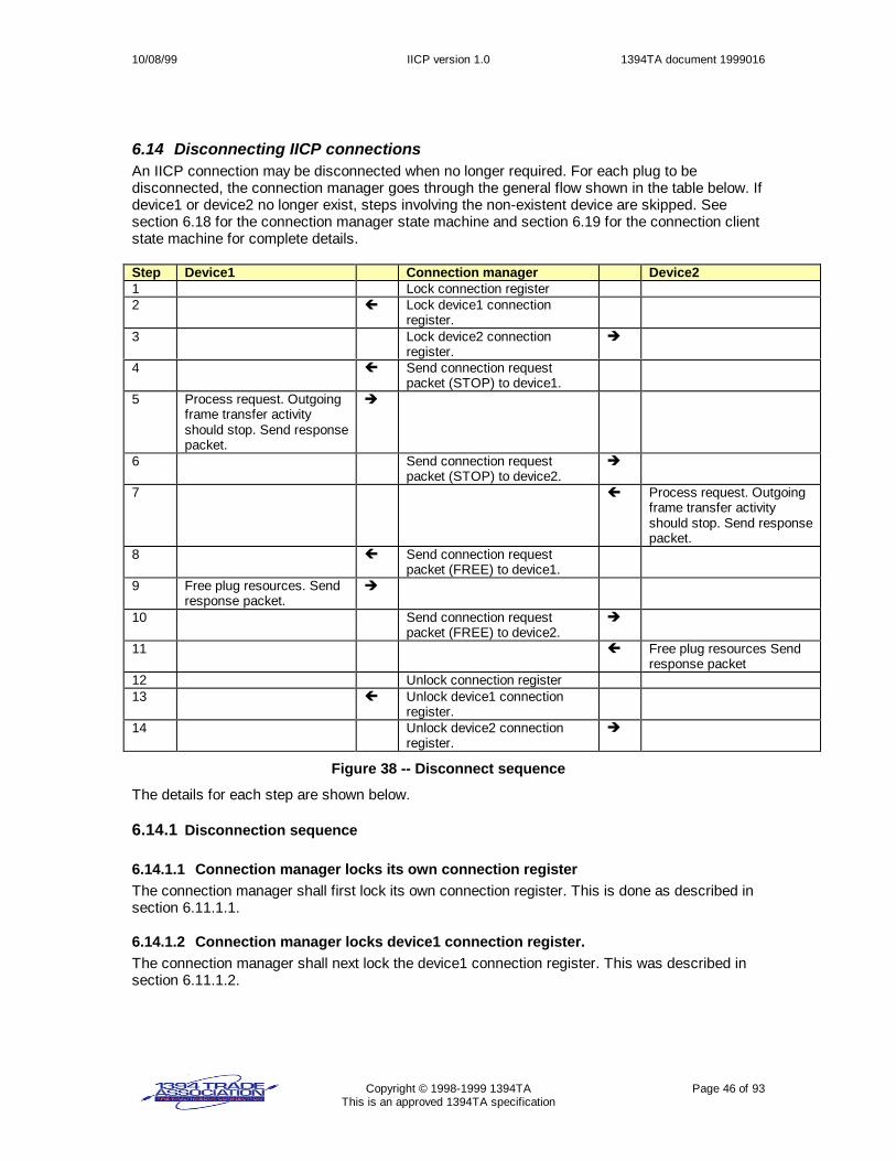
10/08/99 IICP version 1.0 1394TA document 1999016
Copyright © 1998-1999 1394TA Page 46 of 93This is an approved 1394TA specification
6.14 Disconnecting IICP connectionsAn IICP connection may be disconnected when no longer required. For each plug to bedisconnected, the connection manager goes through the general flow shown in the table below. Ifdevice1 or device2 no longer exist, steps involving the non-existent device are skipped. Seesection 6.18 for the connection manager state machine and section 6.19 for the connection clientstate machine for complete details.
Step Device1 Connection manager Device21 Lock connection register2 ç Lock device1 connection
register.3 Lock device2 connection
register.è
4 ç Send connection requestpacket (STOP) to device1.
5 Process request. Outgoingframe transfer activityshould stop. Send responsepacket.
è
6 Send connection requestpacket (STOP) to device2.
è
7 ç Process request. Outgoingframe transfer activityshould stop. Send responsepacket.
8 ç Send connection requestpacket (FREE) to device1.
9 Free plug resources. Sendresponse packet.
è
10 Send connection requestpacket (FREE) to device2.
è
11 ç Free plug resources Sendresponse packet
12 Unlock connection register13 ç Unlock device1 connection
register.14 Unlock device2 connection
register.è
Figure 38 -- Disconnect sequence
The details for each step are shown below.
6.14.1 Disconnection sequence
6.14.1.1 Connection manager locks its own connection registerThe connection manager shall first lock its own connection register. This is done as described insection 6.11.1.1.
6.14.1.2 Connection manager locks device1 connection register.The connection manager shall next lock the device1 connection register. This was described insection 6.11.1.2.

10/08/99 IICP version 1.0 1394TA document 1999016
Copyright © 1998-1999 1394TA Page 47 of 93This is an approved 1394TA specification
6.14.1.3 Connection manager locks device2 connection registerThe connection manager shall next lock the device2 connection register. This was described insection 6.11.1.3.
6.14.1.4 Connection manager sends STOP request packet to device1The connection manager next sends a STOP request packet to device1. The format of the STOPrequest packet is shown below. The destination offset is the connection register of device1 + 8(bytes).
Figure 39 -- STOP request packet
• connectPktId identifies the connection packet as a STOP request. See Table 6 --ConnectPktId values in section 6.16.1.
• connectResponseOffset is the 1394 destination offset for the connection response packet,set to the connection manager lock register offset + 8(bytes).
• plugDestinationOffset is the 1394 destination offset for the plug to be stopped.• unique_ID is the 64-bit unique_ID for the connection manager.
6.14.1.5 Device1 processes STOP request and sends response packetWhen device1 sees the STOP request packet, device1 should stop frame transfer activity. If anypart of a frame has been transferred, the remaining part of the frame shall not be sent. NoSmallFrameConsumer or LargeFrameConsumer update is done. After device1 has processed theSTOP request and has stopped all producer activity on the plug, device1 sends a responsepacket as shown in Figure 35 (STATUS). The 1394 destination offset is theconnectResponseOffset identified in the request packet.
6.14.1.6 Connection manager sends STOP packet to device2The connection manager next sends a STOP request packet to device2. The format of thedisconnection packet was shown in Figure 39. The destination offset used in sending the requestpacket is the connection register of device2 + 8 (bytes).
6.14.1.7 Device2 processes STOP request and sends response packetWhen device2 sees the STOP request packet, device2 shall immediately stop frame transfers. Ifany part of a frame has been transferred, the remaining part of the frame is not sent. NoSmallFrameConsumer or LargeFrameConsumer update is done. After device2 has processed theSTOP request and has stopped all producer activity on the plug, device2 sends a responsepacket as shown in Figure 35 (STATUS). The 1394 destination offset is theconnectResponseOffset identified in the request packet.
donnectResponseOffset
plugDestinationOffset
unique_ID (high)
unique_ID (low)
reserved connectPktID=STOP
reserved

10/08/99 IICP version 1.0 1394TA document 1999016
Copyright © 1998-1999 1394TA Page 48 of 93This is an approved 1394TA specification
6.14.1.8 Connection manager sends FREE request to device1The connection manager sends a connection request to device1, telling device1 it may now freeresources associated with the connection.
Figure 40 -- FREE request packet
• ConnectPktId identifies the connection packet as a FREE connection request. See Table 6 -- ConnectPktId values in section 6.16.1.
• connectResponseOffset is the 1394 destination offset for the connection response packet.• plugDestinationOffset is the 1394 destination offset for the plug to be stopped.• unique_ID is the 64-bit unique_ID for the connection manager.
6.14.1.9 Device1 sends response packetDevice1 frees the resources associated with the specified plug, and sends a response packet asshown in Figure 35 (STATUS). The 1394 destination offset is the connectResponseOffsetidentified in the request packet.
6.14.1.10 Connection manager sends FREE request to device2The connection manager next sends a FREE connection request to device2, telling device2 itmay now free resources associated with the connection.
6.14.1.11 Device2 sends response packetDevice2 frees the resources associated with the specified plug, and sends a response packet asshown in Figure 35 (STATUS). The 1394 destination offset is the connectResponseOffsetidentified in the request packet.
6.14.1.12 Unlock the connection registerThe connection manager unlocks its own connection register. This is as described in section6.14.1.12.
6.14.1.13 Unlock the device1 connection registerThe connection manager unlocks the device1 connection register. This is as described in section6.14.1.13.
6.14.1.14 Unlock the device2 connection registerThe connection manager next unlocks the device2 connection register. This is as described insection 6.14.1.14.
connectResponseOffset
plugDestinationOffset
unique_ID (high)
unique_ID (low)
reserved connectPktID=FREE
reserved

10/08/99 IICP version 1.0 1394TA document 1999016
Copyright © 1998-1999 1394TA Page 49 of 93This is an approved 1394TA specification
6.15 Obtaining connection informationA device may wish to query other IICP devices to obtain information about the IICP connectionsthat exist on a device. This may be useful after a connection manager reset, or for IICPdebugging.
6.15.1 Connection information sequenceThe device gathering information goes through the general flow shown in the table below. Thedevice gathering information is referred to as the connection manager since it is responsible forlocking the connection registers. The device may or may not have actually created theconnection. The device giving the information is referred to as a connection client, since it isresponding to connection register requests. See section 6.18 for the connection manager statemachine and section 6.19 for the connection client state machine for complete details.
Step Connection Manager (obtaining information) Connection Client (providing information)1 Lock connection manager connection register.2 Lock connection client connection register. è3 Sends connect request packet (GETINFO) to
connection client.è
4 ç Process request. Sends connect responsepacket (INFO).
5 Save information from INFO packet. SendGETPLUGINFO request to get information on plug#1 of N.
è
6 ç Process request. Send response packet.
7 Repeat steps 5,68 Unlock connection manager connection register9 Unlock connection client connection register è
Figure 41 -- Connection information sequence
The details for each step are shown below. Note that a connection manager may also lock theconnection registers and then send a GETPLUGINFO for each plug of interest, then unlock theconnection registers.
6.15.1.1 Connection manager locks its own connection registerThe connection manager must lock its own connection register. This is discussed in section6.11.1.1.
6.15.1.2 Connection manager locks the connection client lock registerThe connection manager shall next lock the connection client connection register. This isdiscussed in section 6.11.1.2.
6.15.1.3 Connection manager sends GETINFO request to connection clientThe connection manager next sends a connection request packet (GETINFO) to the connectionclient. The format of the request packet is shown below. The destination offset is the connectionregister of the connection client + 8 (bytes).
Figure 42 -- GETINFO request packet
reserved connectPktID=GETINFO
connectResponseOffset

10/08/99 IICP version 1.0 1394TA document 1999016
Copyright © 1998-1999 1394TA Page 50 of 93This is an approved 1394TA specification
• connectPktId identifies the connection packet as a request to get plug information. SeeTable 6 -- ConnectPktId values in section 6.16.1.
• connectResponseOffset is the 1394 destination offset for the connection response packet.
6.15.1.4 Connection client processes GETINFO and sends response packetWhen the connection client sees the GETINFO request packet, the connection client generates alist of all current plugs. This list shall remain intact until the connection register is unlocked. Theconnection client formulates a response packet with the format shown below.
Figure 43 -- INFO response packet
• connectPktId identifies the connection packet as a connection response. See Table 6 --ConnectPktId values in section 6.16.1.
• connectRequestStatus is an indication of success or failure. A zero-value indicatessuccess. See section 6.16.2.
• numberOfConnections specifies the number of IICP connections allocated on theconnection client.
• first_plugDestinationOffset specifies a destination offset for the first plug in the list of plugsgenerated by the connection client.
If connectRequestStatus is not equal to CRS_SUCCESS, the connection manager shall unlockthe connection registers and return an error to the application.
6.15.1.5 Connection manager sends GETPLUGINFO request to connection clientThe connection manager may next obtain information about specific plugs on the connectionclient by sending a GETPLUGINFO request packet. The format of the request packet is shownbelow. The destination offset is the connection register of the connection client + 8 (bytes).
Figure 44 -- GETPLUGINFO request packet
• connectPktId identifies the connection packet as a request to get plug information. SeeTable 6 -- ConnectPktId values in section 6.16.1.
• connectResponseOffset is the 1394 destination offset for the connection response packet.• plugDestinationOffset specifies the plug the connection manager wishes to obtain
information about.
6.15.1.6 Connection client processes GETPLUGINFO, sends PLUGINFO response packetIf the specified plug exists, the connection client sends a response packet, with information on thespecified plug, as shown below. The 1394 destination offset is the connectResponseOffsetidentified in the request packet. If the specified plug does not exist, the connection client sends aresponse packet (STATUS) as shown in Figure 35, with connectRequestStatus = CRS_PARM.
reserved connectPktID=INFO reserved connectRequestStatus
numberOfConnections
first_plugDestinationOffset
reserved
reserved connectPktID=GETPLUGINFO
connectResponseOffset
reserved
plugDestinationOffset

10/08/99 IICP version 1.0 1394TA document 1999016
Copyright © 1998-1999 1394TA Page 51 of 93This is an approved 1394TA specification
Figure 45 -- PLUGINFO response packet
• connectPktId identifies the connection packet as a connection response. See Table 6 --ConnectPktId values in section 6.16.1.
• connectRequestStatus is an indication of success or failure. A zero-value indicatessuccess. See section 6.16.2. If the GETPLUGINFO request was for a plug that does notexist, or there are no plugs on the connection client, the connectRequestStatus shall be set toCRS_UNKNOWN_PLUG.
• node_ID is the node_ID of the connected node.• plugDestinationOffset specifies the destination offset of the plug.• ctrlLFCS is the current state of the control port large frame consumer state machine. The
consumer state is the decimal number following the ‘CLF’ in the state label. See section 6.20for consumer state machine documentation.
• ctrlSFCS is the current state of the control port small frame consumer state machine. Theconsumer state is the decimal number following the ‘CSF’ in the state label. See section 6.20for consumer state machine documentation.
• ctrlLFPS is the current state of the control port large frame producer state machine. Theproducer state is the decimal number following the ‘LFP’ in the state label. See section 6.21for producer state machine documentation.
• ctrlSFPS is the current state of the control port small frame producer state machine. Theproducer state is the decimal number following the ‘SFP’ in the state label. See section 6.21for producer state machine documentation.
• dataLFCS is the current state of the data port large frame consumer state machine. Theconsumer state is the decimal number following the ‘CLF’ in the state label. See section 6.20for consumer state machine documentation.
• dataSFCS is the current state of the data port small frame consumer state machine. Theconsumer state is the decimal number following the ‘CSF’ in the state label. See section 6.20for consumer state machine documentation.
• dataLFPS is the current state of the data port large frame producer state machine. Theproducer state is the decimal number following the ‘LFP’ in the state label. See section 6.21for producer state machine documentation.
• dataSFPS is the current state of the data port small frame producer state machine. Theproducer state is the decimal number following the ‘SFP’ in the state label. See section 6.21for producer state machine documentation.
plugDestinationOffset
reserved connectPktID=PLUGINFO reserved connectRequestStatus
ctrlLFCS ctrlLFPS dataLFCS dataLFPS
node_ID
reserved command_set_spec_idsesfc
ctrlSFCS ctrlSFPS dataSFCS dataSFPS
reserved
connectedPlugDestinationOffset
connectionParameters (low)
reserved
nextPlugDestinationOffset
connectionParameters (high)
command_set
command_set_detailsreserved
reserved

10/08/99 IICP version 1.0 1394TA document 1999016
Copyright © 1998-1999 1394TA Page 52 of 93This is an approved 1394TA specification
• The sfc-bit is one-valued if the connected node producer indicated it is capable of utilizingsmall frame transfer mode.
• The se-bit is one-valued if the connected node requires sequential writes.• command_set_spec_id indicates the original command_set_spec_id specified when the
connection was established.• command_set indicates the original command_set specified when the connection was
established.• command_set_details indicates the original command_set_details specified when the
connection was established.• connectionParameters indicates the original ConnectionParameters specified when the
connection was established.• connectedPlugDestinationOffset is the destination offset for the plug on the connected
node.• nextPlugDestinationOffset specifies the plugDestinationOffset for the next plug in the list on
the connection client. If this is the last plug in the list generated when the GETINFO requestpacket was received, or if no GETINFO request preceded this GETPLUGINFO request,nextPlugDestinationOffset is set to FFFF FFFF FFFF16.
The consumer and producer state values may be in the process of transition and therefore maybe inaccurate. These values should be a best effort attempt to reflect the current state. Ifimpossible to determine state, an implementation is allowed to return a value of FF16.
If connectRequestStatus is not equal to CRS_SUCCESS, the connection manager shall unlockthe connection registers and return an error to the application.
6.15.1.7 Repeat above 2 stepsThe 2 steps above are repeated until the nextPlugDestinationOffset is 0 or aconnectRequestStatus != CRS_SUCCESS is returned.
6.15.1.8 Connection manager unlocks its connection registerThe connection manager unlocks its connection register. This is as described in section6.14.1.12.
6.15.1.9 Connection manager unlocks connection client registerThe connection manager next unlocks the connection client register. This is as described insection 6.14.1.14.

10/08/99 IICP version 1.0 1394TA document 1999016
Copyright © 1998-1999 1394TA Page 53 of 93This is an approved 1394TA specification
6.16 Summary of connection packet fields
6.16.1 ConnectPktId valuesThe table below enumerates the values for the 8-bit ConnectPktId.
ConnectPktIdMacro
ConnectPktIdValue(Decimal)
Definition
CREQ1 1 Connection request packet sent to begin a connection sequence.CREQ2 2 Connection request packet sent that includes the connected
node plug information.REACT 3 Connection request packet issued to reactivate a connection.STOP 4 Connection request packet issued to stop plug activity.FREE 5 Free plug resources.GETINFO 6 Get information about the total number of connections on a
node.GETPLUGINFO 7 Get information about a specific plug on a node.CRESP 128 Connection response packet sent after processing a CREQ1.STATUS 129 General response packet sent after receiving REACT, STOP, or
FREE.INFO 130 Response packet providing the total number of connections on a
node.PLUGINFO 131 Response packet providing information on a specific plug on a
node.0,8-127,132-255 Reserved
Table 6 -- ConnectPktId values
6.16.2 connectRequestStatus valuesconnectRequestStatus is used in all connection response packets as an indication of success orfailure. The table below summarizes connection response values.

10/08/99 IICP version 1.0 1394TA document 1999016
Copyright © 1998-1999 1394TA Page 54 of 93This is an approved 1394TA specification
connectRequestStatusMacro
connectRequestStatusDecimal Value
Definition
CRS_SUCCESS 0 SuccessCRS_RSRC 1 Rejected- not enough resourcesCRS_PARM 2 Rejected-illegal parameter in requestCRS_UNKNOWN_PLUG 3 Rejected-unknown plugCRS_REG_NOT_LOCKED 4 Connection Register not locked, or not
locked by the sender of the connectionrequest.
CRS_NOT_IN_DEACTIVATED_STATE 5 Connection received a reactivation requestand was not in the deactivated state.
CRS_NOT_STOPPED 6 Connection received a request to free plugresources but either the producer orconsumer were not stopped yet.
CRS_BUS_RESET 7 A request failed due to a bus reset.CRS_NO_DEV 8 A request fails because the device no longer
is found on the bus.CRS_CONNECT_REQ_TIMEOUT 9 Request failed because a connection request
was sent and a connection response was notreceived in CONNECT_REQ_TIMEOUT.
10-254 ReservedCRS_FAIL 255 Failure, unspecified reason.
Table 7 -- connectRequestStatus values
6.17 Miscellaneous macro values
Time Macro Decimal Value DefinitionCCLI_LOCK_TIMEOUT 10000 Number of milliseconds a connection client is allowed to
remain locked. If this time expires, the connection clientshall assume something anomalous occurred, and willunlock its own connection register.
REACT_TIMEOUT 10000 Number of milliseconds a node will wait after a bus reset forthe connections to be reactivated. All connections notreactivated in this time may then be assumed to be stale,and the plug resources may be freed when necessary tocomplete new connection requests successfully.
CONNECT_REQ_TIMEOUT 1000 Number of milliseconds to wait after sending anacknowledged connection request packet before the senderof the packet will time out.
Table 8 -- Miscellaneous macro values

10/08/99 IICP version 1.0 1394TA document 1999016
Copyright © 1998-1999 1394TA Page 55 of 93This is an approved 1394TA specification
6.18 Connection manager state machineThe table below explains terms used in the following connection manager state machine.
Term ExplanationBusReset A 1394 bus reset occurrence.CM_busReset() Called by the connection manager to perform all necessary activities after a bus
reset.CMGR Shorthand for the connection manager.CMGR.lock The connection lock register for the connection manager.F False = 0.Indication(value) Sets up a value to be returned to the caller that initiated the request. The full return
value may be made up of more than one indication value, since some requestscommunicate to more than one device.
Lock(dev,arg_val, data_val)
Sends a 1394 lock request (compare and swap to a device) and waits for the lockresponse packet.
LockRegisters() Locks the specified connection registers. See section 6.18.2.QueueRequest(req) Queue a connection request to the connection manager.Send(dev,PktID) Send a connection request packet to device=dev with connectPktID=PktID and waits
for a connection response packet. Returns a connectRequestStatus value. If devicefails to send a connection response packet and a connection request timeout occurs,the returned connectRequestStatus is set to CRS_CONNECT_REQ_TIMEOUT.
T True = 1.TestAndSet() An atomic (non-interruptible) operation done on the connection manager lock
register. If the lock register is 0-valued prior to this operation, the TestAndSet() willbe successful and the value is set to CMGR unique_ID. If the lock register is not 0-valued prior to this operation, the TestAndSet() will fail. TestAndSet() may succeed iffor some reason if the lock register value is already equal to the CMGR unique_ID.
UngetRequest() Re-queues the current request so the request will be retried later.UnlockRegisters() Unlocks the specified connection registers. See section 6.18.3.
Table 9 -- Connection manager state machine terminology

10/08/99 IICP version 1.0 1394TA document 1999016
Copyright © 1998-1999 1394TA Page 56 of 93This is an approved 1394TA specification
6.18.1 Connection manager state machine: request startupConditionState Transi-
tion ActionNew state
BusResetTX0aCM_busReset();
CM0
valid request received from higher layerTX0b CM1
Invalid request received from higher layer
CM0: idle
TX0cIndication(err)
CM0
LockRegisters() fails due to previously locked conditionTX1aSleep(implementation-dependent time);
CM1
LockRegisters() fails due to bus resetTX1bUngetRequest();
CM0
LockRegisters() failsTX1cIndication(err);
CM0
LockRegisters() succeeds && request is to create a plugTX1d CM10
LockRegisters() succeeds && request is to reactivate a plugTX1e CM20
LockRegisters() succeeds && request is to stop a plugTX1f CM30
LockRegisters() succeeds && request is to get plug information.TX1g CM40
LockRegisters() succeeds && request is to get information on aspecific plug only.
CM1: LockRegLockRegisters()
TX1h CM50
Figure 46 -- Connection manager state machine: request startup
State CM0. The connection manager is idle.Transition TX0a. A bus reset occurs.Transition TX0b. A valid request is received from a higher protocol layer or from an application.Transition TX0c. An invalid request is received from a higher protocol layer or from anapplication. An error indication is returned.
State CM1. The connection manager calls LockRegisters() to lock the connection registers of alldevices to be involved in the connection request.Transition TX1a. LockRegisters() fails due to a previously locked condition. The connectionmanager shall retry after an implementation dependent time.Transition TX1b. LockRegisters() fails due to a bus reset. UngetRequest() re-queues the originalrequest.Transition TX1c. LockRegisters() fails due to some other condition. An error indication isreturned.Transition TX1d. LockRegisters() succeeds and the request is to create a plug.Transition TX1e. LockRegisters() succeeds and the request is to reactivate a plug.Transition TX1f. LockRegisters() succeeds and the request is to stop plug activity.Transition TX1g. LockRegisters() succeeds and the request is to get plug information.Transition TX1h. LockRegisters() succeeds and the request is to get information for a specificplug.

10/08/99 IICP version 1.0 1394TA document 1999016
Copyright © 1998-1999 1394TA Page 57 of 93This is an approved 1394TA specification
6.18.2 Connection manager state machine: LockRegisters(device1,device2)ConditionState Transi-
tion ActionNew state
BusResetTX0aCMGR.lock = 0; Indication(not locked due to bus reset);CM_busReset();
Return to caller
TestAndSet() failsTX0bIndication(not locked due to previously locked condition);
Return to caller
device1 != CMGRTX0c L1
Lock2 == 1TX0d L2
L0:TestAndSet() onCMGR.lock
TX0eIndication(lock success);
Return to caller
BusResetTX1aCMGR.lock = 0; Indication(not locked due to bus reset);CM_busReset();
Return to caller
Lock response indicates successful lock && Lock2TX1b L2
Lock response indicates device1 not successfully lockedTX1cCMGR.lock = 0; Indication(not locked due to locked condition);
Return to caller
Lock response indicates successful lock && !Lock2
L1:Lock(device1,arg_value=0,data_value= CMGR uid);
TX1dIndication(lock success);
Return to caller
BusResetTX2aCMGR.lock = 0; Indication(not locked due to bus reset);CM_busReset();
Return to caller
Lock response indicates successful lockTX2bIndication(lock success);
Return to caller
Lock response indicates device2 not successfully locked
L2:Lock (device2,arg_value=0,data_value= CMGR uid );
TX2cCMGR.lock = 0;UnlockRegisters(Unlock2=F);Indication(not locked due to locked condition);
Return to caller
Figure 47 -- Connection manager state machine: LockRegisters()
The call to LockRegisters() specifies a device (device1) or devices (device1, device2) to belocked, along with a variable Lock2 that determines if a second device, device2, is to be locked.The connection manager may be the same as device1.
State L0. Upon entry, the connection manager attempts an atomic test-and-set operation on theconnection manager’s connection lock register, abbreviated as CMGR.lock.Transition TX0a. A bus reset occurs. The connection manager lock register is cleared and anindication is returned indicating the lock failed due to a bus reset. CM_busReset() is called.Transition TX0b. The connection manager’s lock register is already locked by another node. Anindication is returned indicating the lock failed due to a locked condition.Transition TX0c. All preceding conditions tested false, and device1 is not the connectionmanager.Transition TX0d. All preceding conditions tested false, and there is a second device is to belocked.Transition TX0e. All preceding conditions tested false, and no additional devices are to belocked. A successful lock indication is returned.

10/08/99 IICP version 1.0 1394TA document 1999016
Copyright © 1998-1999 1394TA Page 58 of 93This is an approved 1394TA specification
State L1. Upon entry, a lock request is sent to device1 in an attempt to lock the device1connection lock register. The connection manager then waits for a lock response.Transition TX1a. A bus reset occurs. The connection manager’s lock register is cleared. An“unlocked due to bus reset” indication is returned. CM_busReset() is called.Transition TX1b. Device1 returns a lock response indicating the lock request succeeded andthere is a second device to be locked.Transition TX1c. Device1 returns a lock response indicating the lock request failed. Theconnection manager’s lock register is cleared. An “unlocked due to previously locked condition”indication is returned.Transition TX1d. Device1 returns a lock response indicating the lock request succeeded andthere is not a second device to be locked. A successfully locked indication is returned.
State L2. Upon entry, a lock request is sent to device2 in an attempt to lock the device2connection lock register. The connection manager then waits for a lock response.Transition TX2a. A bus reset occurs. The connection manager’s lock register is cleared. An“unlocked due to bus reset” indication is returned. CM_busReset() is called.Transition TX2b. Device2 returns a lock response indicating the lock request succeeded. Asuccessful lock indication is returned.Transition TX2c. Device2 returns a lock response indicating the lock request failed due to apreviously locked condition. UnlockRegisters(Unlock2=F) is called to unlock all locked connectionregisters. An indication of “unlocked due to previously locked condition” is returned.

10/08/99 IICP version 1.0 1394TA document 1999016
Copyright © 1998-1999 1394TA Page 59 of 93This is an approved 1394TA specification
6.18.3 Connection manager state machine: UnlockRegisters()ConditionState Transi-
tion ActionNew state
BusReset before CMGR.lock = 0TX0aIndication(UnlockResult |= 1); CM_busReset();
Return to caller
BusReset after CMGR.lock = 0TX0bIndication(UnlockResult |= 2); CM_busReset();
Return to caller
(CMGR == device1) && !Unlock2TX0cIndication(UnlockResult);
Return to caller
(CMGR == device1) && Unlock2TX0d UL2
CMGR != device1
UL0:UnlockResult = 0;CMGR.lock = 0;
TX0e UL1
BusReset before lock request sentTX1aIndication(UnlockResult |= 0x2); CM_busReset();
Return to caller
BusReset after lock request sent && lock response not receivedTX1bIndication(UnlockResult |= 0x3); CM_busReset();
Return to caller
BusReset after lock response receivedTX1cIndication(UnlockResult |= 0x4); CM_busReset();
Return to caller
Lock response indicates successful unlock && Unlock2TX1d UL2
Lock response indicates successful unlock && !Unlock2TX1eIndication(UnlockResult);
Return to caller
Lock response indicates unlock failure && Unlock2TX1fUnlockResult |= 0x10
UL2
Lock response indicates unlock failure && !Unlock2
UL1:Lock (device1,arg_value = CMGR uid,data_value=0);
TX1gIndication(UnlockResult |= 0x10);
Return to caller
BusReset before lock request sentTX2aIndication(UnlockResult |= 0x4); CM_busReset();
Return to caller
BusReset after lock request sentTX2bIndication(UnlockResult |= 0x5); CM_busReset();
Return to caller
BusReset after response receivedTX2cIndication(UnlockResult |= 0x6); CM_busReset();
Return to caller
Lock response indicates unlock failureTX2dIndication(UnlockResult |= 0x20) ;
Return to caller
Lock response indicates successful unlock
UL2:Lock (device2,arg_value = CMGR uid,data_value=0);
TX2eIndication(UnlockResult);
Return to caller
Figure 48 -- Connection manager state machine: UnlockRegisters()
The call to UnlockRegisters() specifies a device (device1) or devices (device1,device2) to beunlocked. Variable Unlock2 determines if a second device, device2, is to be unlocked. Theconnection manager may be the same as device1. The caller of UnlockRegisters(), in somecases, needs to know the success or failure of the operation, and may need to know if a bus resetoccurred. For this reason, variable UnlockResult contains information on if and when a bus resetoccurred. Additional information indicates the success or failure of unlocking CMGR, device1, anddevice2. A suggested definition for the UnlockResult bits is shown below.

10/08/99 IICP version 1.0 1394TA document 1999016
Copyright © 1998-1999 1394TA Page 60 of 93This is an approved 1394TA specification
UnlockResult Bit Meaning0,1,2 If non-zero, indicates point in the unlock procedure that a bus reset occurred.
0 – no bus reset1 – bus reset before CMGR unlocked2 – bus reset after CMGR unlocked and before unlock request sent to device1.3 – bus reset after unlock request sent to device1 and before lock response.4 – bus reset after unlock response from device1 and before unlock request sent todevice2.5 – bus reset after unlock request sent to device2 and before lock response.6 – bus reset after unlock response from device2.
3 If non-zero, indicates error in unlocking the connection manager. This should neveroccur, but is provided for completeness.
4 If non-zero, indicates an error in unlocking device1.5 If non-zero, indicates an error in unlocking device2.
Table 10 -- Suggested UnlockResult bit definitions
State UL0. Upon entry, UnlockResult is initialized to 0 and the connection manager lock registeris cleared.Transition TX0a. A bus reset occurs before the connection manager’s lock register is unlocked.UnlockResult is modified to indicate this condition and is returned to the caller. CM_busReset() iscalled.Transition TX0b. A bus reset occurs after the connection manager’s lock register has beenunlocked. UnlockResult is modified to indicate this condition and is returned to the caller.CM_busReset() is called.Transition TX0c. The connection manager is the same as device1, and Unlock2 is false. Thereare no more devices to unlock. A successfully unlocked indication is returned to the caller.Transition TX0d. The connection manager is the same as device1, and Unlock2 is true.Transition TX0e. The connection manager is not the same as device1.
State UL1. Upon entry, a compare and swap lock request is sent to device1 in an attempt tounlock the device1 lock register. The connection manager waits for a lock response.Transition TX1a. A bus reset occurs before the unlock request is sent to device1. UnlockResultis modified to indicate this event. UnlockResult is returned to the caller. CM_busReset() is called.Transition TX1b. A bus reset occurs after the unlock request is sent to device1 and before theresponse is received. UnlockResult is modified to indicate this event. UnlockResult is returned tothe caller. CM_busReset() is called.Transition TX1c. A bus reset occurs after the unlock response returns. UnlockResult is modifiedto indicate this event. UnlockResult is returned to the caller. CM_busReset() is called.Transition TX1d. Device1 successfully unlocked and Unlock2 indicates device2 needs to beunlocked.Transition TX1e. Device1 successfully unlocked and there are no more devices to unlock.UnlockResult is returned to the caller.Transition TX1f. Device1 unlock fails. UnlockResult is modified to indicate this condition.Device2 remains to be unlocked.Transition TX1g. Device1 unlock fails. There are no more devices to be unlocked. UnlockResultis modified to indicate this condition. UnlockResult is returned to the caller.
State UL2. Upon entry, a compare-swap lock request is sent to device2 in an attempt to unlockthe device2 lock register. The connection manager waits for a lock response packet.Transition TX2a. A bus reset occurs before the unlock request is sent to device2. UnlockResultis modified to indicate this and is returned to the caller. CM_busReset() is called.Transition TX2b. A bus reset occurs after the unlock request has been sent but before aresponse is received. UnlockResult is modified to indicate this and is returned to the caller.CM_busReset() is called.Transition TX2c. A bus reset occurs after the response is received. UnlockResult is modified toindicate this and is returned to the caller. CM_busReset() is called.
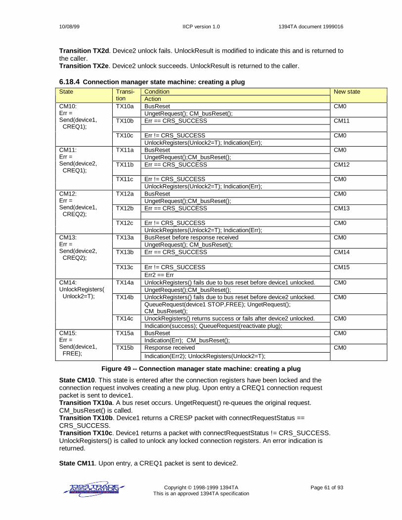
10/08/99 IICP version 1.0 1394TA document 1999016
Copyright © 1998-1999 1394TA Page 61 of 93This is an approved 1394TA specification
Transition TX2d. Device2 unlock fails. UnlockResult is modified to indicate this and is returned tothe caller.Transition TX2e. Device2 unlock succeeds. UnlockResult is returned to the caller.
6.18.4 Connection manager state machine: creating a plugConditionState Transi-
tion ActionNew state
BusResetTX10aUngetRequest(); CM_busReset();
CM0
Err == CRS_SUCCESSTX10b CM11
Err != CRS_SUCCESS
CM10:Err =Send(device1, CREQ1);
TX10cUnlockRegisters(Unlock2=T); Indication(Err);
CM0
BusResetTX11aUngetRequest();CM_busReset();
CM0
Err == CRS_SUCCESSTX11b CM12
Err != CRS_SUCCESS
CM11:Err =Send(device2, CREQ1);
TX11cUnlockRegisters(Unlock2=T); Indication(Err);
CM0
BusResetTX12aUngetRequest();CM_busReset();
CM0
Err == CRS_SUCCESSTX12b CM13
Err != CRS_SUCCESS
CM12:Err =Send(device1, CREQ2);
TX12cUnlockRegisters(Unlock2=T); Indication(Err);
CM0
BusReset before response receivedTX13aUngetRequest(); CM_busReset();
CM0
Err == CRS_SUCCESSTX13b CM14
Err != CRS_SUCCESS
CM13:Err =Send(device2, CREQ2);
TX13cErr2 == Err
CM15
UnlockRegisters() fails due to bus reset before device1 unlocked.TX14aUngetRequest();CM_busReset();
CM0
UnlockRegisters() fails due to bus reset before device2 unlocked.TX14bQueueRequest(device1 STOP,FREE); UngetRequest();CM_busReset();
CM0
UnockRegisters() returns success or fails after device2 unlocked.
CM14:UnlockRegisters( Unlock2=T);
TX14cIndication(success); QueueRequest(reactivate plug);
CM0
BusResetTX15aIndication(Err); CM_busReset();
CM0
Response received
CM15:Err =Send(device1, FREE);
TX15bIndication(Err2); UnlockRegisters(Unlock2=T);
CM0
Figure 49 -- Connection manager state machine: creating a plug
State CM10. This state is entered after the connection registers have been locked and theconnection request involves creating a new plug. Upon entry a CREQ1 connection requestpacket is sent to device1.Transition TX10a. A bus reset occurs. UngetRequest() re-queues the original request.CM_busReset() is called.Transition TX10b. Device1 returns a CRESP packet with connectRequestStatus ==CRS_SUCCESS.Transition TX10c. Device1 returns a packet with connectRequestStatus != CRS_SUCCESS.UnlockRegisters() is called to unlock any locked connection registers. An error indication isreturned.
State CM11. Upon entry, a CREQ1 packet is sent to device2.

10/08/99 IICP version 1.0 1394TA document 1999016
Copyright © 1998-1999 1394TA Page 62 of 93This is an approved 1394TA specification
Transition TX11a. A bus reset occurs. UngetRequest() re-queues the original request.CM_busReset() is called.Transition TX11b. Device2 returns a CRESP packet with connectRequestStatus ==CRS_SUCCESS.Transition TX11c. Device2 returns a packet with connectRequestStatus != CRS_SUCCESS.UnlockRegisters() is called to unlock any locked connection registers. An error indication isreturned.
State CM12. Upon entry, a CREQ2 packet is sent to device1.Transition TX12a. A bus reset occurs. UngetRequest() re-queues the original request.CM_busReset() is called.Transition TX12b. Device1 returns a STATUS packet with connectRequestStatus ==CRS_SUCCESS.Transition TX12c. Device1 returns a STATUS packet with connectRequestStatus !=CRS_SUCCESS. UnlockRegisters() is called to unlock any locked connection registers. An errorindication is returned.
State CM13. Upon entry, a CREQ2 packet is sent to device2.Transition TX13a. A bus reset occurs before a response is received. UngetRequest() re-queuesthe original request. CM_busReset() is called.Transition TX13b. Device2 returns a STATUS packet with connectRequestStatus ==CRS_SUCCESS.Transition TX13c. Device2 returns a STATUS packet with unexpected connectRequestStatus.Err2 is set to the connectRequestStatus.
State CM14. Upon entry, UnlockRegisters(Unlock2=T) is called to unlock the connectionregisters.Transition TX14a. UnlockRegisters() fails due to a bus reset before device1 is unlocked.UngetRequest() is called to re-queue the original request.Transition TX14b. UnlockRegisters() fails due to bus reset after device1 is unlocked but beforedevice2 is unlocked. A request to STOP and FREE the newly created plug on device1 is queued.UngetRequest() re-queues the original request. CM_busReset() is called.Transition TX14c. UnlockRegisters() returns success or returns failure, but the failure occursafter device2 unlocked. The connection remains valid. QueueRequest() is called to queue areactivation request for the newly created plug.
State CM15. Upon entry, a FREE request is sent to device1.Transition TX15a. A bus reset occurs. The error indication from device2 is returned.CM_busReset() is called.Transition TX15b. A response is received. UnlockRegisters() is called. The error indication fromdevice2 is returned.
.

10/08/99 IICP version 1.0 1394TA document 1999016
Copyright © 1998-1999 1394TA Page 63 of 93This is an approved 1394TA specification
6.18.5 Connection manager state machine: reactivating a connectionConditionState Transi-
tion ActionNew state
BusResetTX20aCM_busReset();
CM0
(Err == CRS_SUCCESS) ||(Err == CRS_NOT_IN_DEACTIVATED_STATE)
TX20b CM21
CM20Err =Send(device1, REACT);
TX20cUnlockRegisters(Unlock2=T);Indication(Err);
CM0
BusResetTX21aCM_busReset();
CM0
(Err == CRS_SUCCESS) ||(Err == CRS_NOT_IN_DEACTIVATED_STATE)
TX21b CM23
CM21Err =Send(device2, REACT);
TX21cErr2 = Err;
CM22
BusResetTX22aIndication(Err2); CM_busReset();
CM0
Response received
CM22Err =Send(device1, FREE);
TX22bUnlockRegisters(Unlock2=T); Indication(Err2);
CM0
UnlockRegisters() completesCM23UnlockRegisters(Unlock2=T);
TX23aIndication(Err);
CM0
Figure 50 -- Connection manager state machine: reactivating a plug
State CM20. This state is entered after the connection registers have been locked and theconnection request involves reactivating a plug. Upon entry, a REACT connection request packetis sent to device1.Transition TX20a. A bus reset occurs. CM_busReset() will reschedule a reactivation request.Transition TX20b. Device1 returns a STATUS response packet with connectRequestStatus ==CRS_SUCCESS or CRS_NOT_IN_DEACTIVATED_STATE.Transition TX20c. Device1 returns a response packet with an unexpectedconnectRequestStatus. UnlockRegisters() is called to unlock any locked connection registers. Anerror indication is returned.
State CM21. Upon entry, a REACT connection request packet is sent to device2.Transition TX21a. A bus reset occurs. CM_busReset() is called and will reschedule areactivation request.Transition TX21b. Device2 returns a response packet with connectRequestStatus ==CRS_SUCCESS or CRS_NOT_IN_DEACTIVATED_STATE.Transition TX21c. Device2 returns a response packet with an unexpectedconnectRequestStatus. Variable Err2 is set to Err to be returned later.
State CM22. Upon entry, a FREE request packet is sent to device1 to free the plug.Transition TX22a. A bus reset occurs. Error indication Err2 is returned. CM_busReset() is called.Transition TX22b. Device1 returns a response packet. UnlockRegisters() is called to unlock anylocked connection registers. Error indication Err2 is returned.
State CM23. Upon entry, UnlockRegisters(Unlock2=T) is called to unlock connection registers.Transition TX23a. UnlockRegisters() completes. An indication made up of Err is returned.
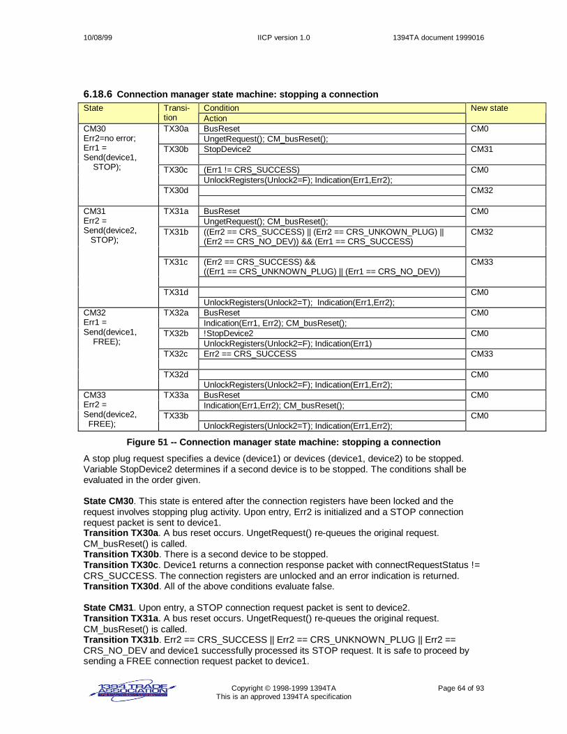
10/08/99 IICP version 1.0 1394TA document 1999016
Copyright © 1998-1999 1394TA Page 64 of 93This is an approved 1394TA specification
6.18.6 Connection manager state machine: stopping a connectionConditionState Transi-
tion ActionNew state
BusResetTX30aUngetRequest(); CM_busReset();
CM0
StopDevice2TX30b CM31
(Err1 != CRS_SUCCESS)TX30cUnlockRegisters(Unlock2=F); Indication(Err1,Err2);
CM0
CM30Err2=no error;Err1 =Send(device1, STOP);
TX30d CM32
BusResetTX31aUngetRequest(); CM_busReset();
CM0
((Err2 == CRS_SUCCESS) || (Err2 == CRS_UNKOWN_PLUG) ||(Err2 == CRS_NO_DEV)) && (Err1 == CRS_SUCCESS)
TX31b CM32
(Err2 == CRS_SUCCESS) &&((Err1 == CRS_UNKNOWN_PLUG) || (Err1 == CRS_NO_DEV))
TX31c CM33
CM31Err2 =Send(device2, STOP);
TX31dUnlockRegisters(Unlock2=T); Indication(Err1,Err2);
CM0
BusResetTX32aIndication(Err1, Err2); CM_busReset();
CM0
!StopDevice2TX32bUnlockRegisters(Unlock2=F); Indication(Err1)
CM0
Err2 == CRS_SUCCESSTX32c CM33
CM32Err1 =Send(device1, FREE);
TX32dUnlockRegisters(Unlock2=F); Indication(Err1,Err2);
CM0
BusResetTX33aIndication(Err1,Err2); CM_busReset();
CM0CM33Err2 =Send(device2, FREE);
TX33bUnlockRegisters(Unlock2=T); Indication(Err1,Err2);
CM0
Figure 51 -- Connection manager state machine: stopping a connection
A stop plug request specifies a device (device1) or devices (device1, device2) to be stopped.Variable StopDevice2 determines if a second device is to be stopped. The conditions shall beevaluated in the order given.
State CM30. This state is entered after the connection registers have been locked and therequest involves stopping plug activity. Upon entry, Err2 is initialized and a STOP connectionrequest packet is sent to device1.Transition TX30a. A bus reset occurs. UngetRequest() re-queues the original request.CM_busReset() is called.Transition TX30b. There is a second device to be stopped.Transition TX30c. Device1 returns a connection response packet with connectRequestStatus !=CRS_SUCCESS. The connection registers are unlocked and an error indication is returned.Transition TX30d. All of the above conditions evaluate false.
State CM31. Upon entry, a STOP connection request packet is sent to device2.Transition TX31a. A bus reset occurs. UngetRequest() re-queues the original request.CM_busReset() is called.Transition TX31b. Err2 == CRS_SUCCESS || Err2 == CRS_UNKNOWN_PLUG || Err2 ==CRS_NO_DEV and device1 successfully processed its STOP request. It is safe to proceed bysending a FREE connection request packet to device1.

10/08/99 IICP version 1.0 1394TA document 1999016
Copyright © 1998-1999 1394TA Page 65 of 93This is an approved 1394TA specification
Transition TX31c. Err2 == CRS_SUCCESS and device1 was not successfully stopped, but it issafe to proceed and send FREE connection request packet to device2.Transition TX31d. All of the above conditions evaluate false.
State CM32. Upon entry, a FREE request packet is sent to device1.Transition TX32a. A bus reset occurs. An indication made up of Err1, Err2 is set up to bereturned. CM_busReset() is called.Transition TX32b. There is not a second device to be stopped.Transition TX32c. Err2 == CRS_SUCCESS.Transition TX32d. All of the above conditions evaluate false.
State CM33. Upon entry, a FREE connection request packet is sent to device2.Transition TX33a. A bus reset occurs. CM_busReset() is called.Transition TX33b. UnlockRegisters(Unlock2=T) is called. An indication made up of Err1, Err2 isreturned.
6.18.7 Connection manager state machine: get plug informationConditionState Transi-
tion ActionNew state
BusResetTX40aUngetRequest(); CM_busReset();
CM0
Err != CRS_SUCCESSTX40bUnlockRegisters(Unlock2=F); Indication(Err);
CM0
NumberOfConnections == 0TX40cUnlockRegisters(Unlock2=F); Indication(INFO);
CM0
NumberOfConnections > 0
CM40Err = Send(device,GETINFO);
TX40dSave information
CM41
BusResetTX41aUngetRequest(); CM_busReset();
CM0
Err != CRS_SUCCESSTX41bUnlockRegisters(Unlock2=F); Indication(Err);
CM0
More plug information to getTX41cSave information
CM41
no more plug information to get
CM41Err = Send(device, GETPLUGINFO);
TX41dSave information; UnlockRegisters(Unlock2=F);Indication(success,INFO,accumulated plug information);
CM0
Figure 52 -- Connection manager state machine: get plug information
State CM40: Upon entry, the connection manager sends a GETINFO request packet to thedevice.Transition TX40a. A bus reset occurs. UngetRequest() re-queues the original request.CM_busReset() is called.Transition TX40b. A response is received with connectRequestStatus != CRS_SUCCESS. Theconnection registers are unlocked. An error indication is returned.Transition TX40c. The number of connections, or plugs, is 0. UnlockRegisters() is called. Anindication made up of the INFO response packet is returned.Transition TX40d. The number of connections, or plugs, is greater than 0.
State CM41. Upon entry, a GETPLUGINFO request packet is sent to the device.Transition TX41a. A bus reset occurs. UngetRequest() re-queues the original request.CM_busReset() is called.Transition TX41b. A response packet is received with connectRequestStatus !=CRS_SUCCESS. The connection registers are unlocked and an error is returned.Transition TX41c. There is more information to get from the device.Transition TX41d. There is no more information to get from the device. An indication made up ofthe INFO response packet and the accumulated PLUGINFO response packets is returned.

10/08/99 IICP version 1.0 1394TA document 1999016
Copyright © 1998-1999 1394TA Page 66 of 93This is an approved 1394TA specification
6.18.8 Connection manager state machine: get specific plug informationConditionState Transi-
tion ActionNew state
BusResetTX50aUngetRequest(); CM_busReset();
CM0
Err != CRS_SUCCESSTX50bUnlockRegisters(Unlock2=F); Indication(Err);
CM0
Err == CRS_SUCCESS
CM50Err = Send( device, GETPLUGINFO);
TX50cUnlockRegisters(Unlock2=F); Indication(PLUGINFO);
CM0
Figure 53 -- Connection manager state machine: get specific plug information
State CM50: Upon entry, the connection manager sends a GETPLUGINFO request packet to thedevice.Transition TX50a. A bus reset occurs. UngetRequest() re-queues the original request.CM_busReset() is called.Transition TX50b. A response packet is received with connectRequestStatus !=CRS_SUCCESS. The connection registers are unlocked and an error is returned.Transition TX50c. A response packet is received with connectRequestStatus ==CRS_SUCCESS. The connection registers are unlocked and the plug information is returned.
6.18.9 Connection manager state machine: CM_busReset()This state machine documents the connection manager activities required after a bus reset.
ConditionState Transi-tion Action
New state
(CMGR.lock == CMGR unique_ID ) ||(CMGR.lock != 0 && CMGR.lock occurred prior to bus reset)
TX0a
CMGR.lock = 0;
CMBR1CMBR0:De-queue allreactivationrequests TX0b CMBR1
BusResetTX1a CMBR0
Enumeration complete
CMBR1Enumerate the1394 bus. TX1b
Queue reactivation requests;CM0
Figure 54 -- Connection manager state machine: CM_busReset()
State CM_BR0: Upon entry, all reactivation requests that are queued are de-queued.Transition TX0a. The connection manager lock register is currently locked by the connectionmanager or is locked by another node but the lock occurred prior to the bus reset event. The lockregister is unlocked.Transition TX0b. The above condition evaluates false.
State CM_BR1. Upon entry, the bus is enumerated. This involves the connection manager goingthrough a process of discovery to find what IICP devices exist on the bus.Transition TX1a. A bus reset occurs.Transition TX1b. The enumeration is done. The connection manager queues the appropriatereactivation requests.

10/08/99 IICP version 1.0 1394TA document 1999016
Copyright © 1998-1999 1394TA Page 67 of 93This is an approved 1394TA specification
6.19 Connection client state machineThe table below explains terms used in the following connection client state machine.
Term ExplanationBusReset A 1394 bus reset occurrence.CC_busReset() Called by the connection client to perform all necessary activities after a bus reset.
This will deactivate all plugs.CCLI_UnlockEvent Event indicating an action to be performed after the connection register is unlocked.F False = 0.LockTimeout() Returns true if the connection client timer has expired. The timer expires after
CCLI_LOCK_TIMEOUT.Send(pktID, status) Sends a connection response packet with connectRequestPktID = pktID and
connectRequestStatus = status. If a bus reset occurs, the send is aborted. If Send()fails, an error should be logged.
T True = 1.UnlockOK Variable set true if connection client expects an unlock request.
Table 11 -- Connection client state machine terminology

10/08/99 IICP version 1.0 1394TA document 1999016
Copyright © 1998-1999 1394TA Page 68 of 93This is an approved 1394TA specification
6.19.1 Locking of connection register and waiting for requestConditionState Transi-
tion ActionNew state
BusResetTX0aCC_busReset();
CC0
Valid lock requestTX0bSend lock response; initialize LockTimeout() timer;ValidRequests = CREQ1, REACT, STOP,GETINFO,GETPLUGINFO; UnlockOK=T; CCLI_UnlockEvent = NULL;
CC1
Invalid lock requestTX0cSend lock response
CC0
Connect request packet receivedTX0dRcode = resp_type_error; Send(STATUS,CRS_NOT_LOCKED);
CC0
Connect response packet received
CC0: unlockedUnlockOK=F;
TX0eRcode = resp_type_error;
CC0
Bus resetTX1aFree any resources allocated since connection register was locked;Unlock connection lock register; CC_busReset();
CC0
Lock request == lock || invalid unlock requestTX1bSend lock response
CC1
Lock request == valid unlock request && UnlockOK == TTX1cUnlock connection lock register; Send lock response;if ( CCLI_UnlockEvent == Reactivation ) Send ReactivationEvent to producer and consumer state machines.else if ( CCLI_UnlockEvent == PlugCreation ) Send CreationEvent to consumer state machines
CC0
Lock request == valid unlock request && UnlockOK == FTX1dUnlock connection lock register; Free any resources allocated sinceconnection register was locked. Send lock response
CC0
LockTimeout()TX1eFree any resources allocated since connection register was locked;Unlock connection lock register;
CC0
Invalid request receivedTX1fRcode = resp_type_error; Send(STATUS,CRS_PARM);
CC1
Connection response packet received.TX1gRcode = resp_type_error;
CC1
Valid request received && request == CREQ1TX1hUnlockOK=F;
CC10
Valid request received && request == CREQ2TX1k CC20
Valid request received && request == REACTTX1m CC30
Valid request received && request == STOPTX1n CC40
Valid request received && request == FREETX1p CC50
Valid request received && request == GETINFOTX1q CC60
Valid request received && request == GETPLUGINFO
CC1: lockedWait for aconnectionrequest or forunlock request
TX1r CC70
Figure 55 -- Connection client state machine: locking and waiting for request
State CC0. The connection client lock register is unlocked.Transition TX0a. A bus reset occurs. CC_busReset() is called.

10/08/99 IICP version 1.0 1394TA document 1999016
Copyright © 1998-1999 1394TA Page 69 of 93This is an approved 1394TA specification
Transition TX0b. A valid lock request is received. A lock response is sent. The LockTimeout()timer is initialized. A variable, ValidRequests, is initialized to the set of connection requests thatwill be treated as valid requests. Variable UnlockOK is set true. Variable CCLI_UnlockEvent is setto NULL, indicating there is not yet an event to be communicated when the connection register isunlocked.Transition TX0c. An invalid lock request is received. An appropriate lock response is returned.Transition TX0d. An unexpected connect request packet is received. A response code =resp_type_error should be returned. A response packet is sent, with connectPktID = STATUSand connectRequestStatus = CRS_NOT_LOCKED.Transition TX0e. An unexpected connect response packet is received. A response code =resp_type_error should be returned.
State CC1. The connection client’s lock register is locked. The connection client waits for aconnection request or unlock.Transition TX1a. A bus reset occurs. Any resources allocated in the handling of connectionrequests since the connection register was locked shall be freed. The connection client lockregister is unlocked. CC_busReset() is called.Transition TX1b. A lock request or invalid unlock request is received. An appropriate lockresponse is sent.Transition TX1c. A valid, expected unlock request is received. The connection client lock registeris unlocked. A lock response is sent. If CCLI_UnlockEvent is set, perform the appropriatecommunication to the consumer and producer state machines.Transition TX1d. A valid, but unexpected, unlock request is received. The connection client lockregister is unlocked. A lock response is sent. Any resources allocated in the handling ofconnection requests since the connection register was locked should be freed.Transition TX1e. A LockTimeout() occurs. Any resources allocated in the handling of connectionrequests since the connection register was locked should be freed. The connection client lockregister is unlocked.Transition TX1f. An invalid connection request is received. A response code = resp_type_errorshould be returned. A response packet is sent, with connectPktID = STATUS andconnectRequestStatus = CRS_PARM.Transition TX1g. An invalid connection response packet is received. A response code =resp_type_error should be returned.Transition TX1h – Transition TX1r. A valid connection request packet is received and theconnection client state machine moves to the appropriate state to handle the request.
6.19.2 Connection client request == CREQ1ConditionState Transi-
tion ActionNew state
BusResetTX10aFree any resources allocated; Unlock connection register;CC_busReset();
CC0
Processing of CREQ1 request successful.TX10bSend(CRESP,CRS_SUCCESS); ValidRequests = CREQ2
CC1
Processing of CREQ1 request fails
CC10:Process theCREQ1 request
TX10cSend(CRESP,appropriate status); ValidRequests = none;
CC1
Figure 56 -- Connection client state machine: CREQ1 processing
State CC10. The connection client processes the CREQ1 packet. This involves creating a newplug.Transition TX10a. A bus reset occurs. Any resources allocated for the new plug are freed. Theconnection client’s lock register is unlocked. CC_busReset() is called.Transition TX10b. The plug is successfully created. A response packet is sent. The next validrequest is CREQ2.Transition TX10c. The plug creation failed or a higher layer is not yet ready to handle connectionrequests. A response packet is sent. The set of valid request packets is set to none.

10/08/99 IICP version 1.0 1394TA document 1999016
Copyright © 1998-1999 1394TA Page 70 of 93This is an approved 1394TA specification
6.19.3 Connection client request == CREQ2ConditionState Transi-
tion ActionNew state
BusResetTX20aFree any resources allocated; Unlock connection register;CC_busReset();
CC0
Processing of CREQ2 successful.TX20bSend(STATUS,CRS_SUCCESS); ValidRequests = FREE;CCLI_UnlockEvent = CreationEvent;
CC1
Processing of CREQ2 fails
CC20:Process theCREQ2 request
TX20cSend(STATUS,appropriate status); ValidRequests = none;
CC1
Figure 57 -- Connection client state machine: CREQ2 processing
State CC20. The connection client processes the CREQ2 request.Transition TX20a. A bus reset occurs. Any resources allocated for the new plug are freed. Theconnection client’s lock register is unlocked. CC_busReset() is called.Transition TX20b. The request is processed successfully. A response packet is sent. The onlyvalid following request is FREE. Variable CCLI_UnlockEvent is set so when the connectionregister is unlocked the appropriate event is communicated to the consumer state machines.Transition TX20c. The processing of the request failed. A response packet is sent. The set ofvalid request packets is set to none.
6.19.4 Connection client request == REACTConditionState Transi-
tion ActionNew state
BusResetTX30aUnlock connection register; CC_busReset();
CC0
Plug is deactivatedTX30bNotify consumer and producer state machines of REACT received;Send(STATUS,CRS_SUCCESS); ValidRequests = none;CCLI_Event = Reactivation;
CC1
Plug not deactivated
CC30:Check if plug isdeactivated.
TX30cSend(STATUS,CRS_NOT_IN_DEACTIVATED_STATE);ValidRequests = none;
CC1
Figure 58 -- Connection client state machine: REACT processing
State CC30. The connection client checks if the plug is deactivated.Transition TX30a. A bus reset occurs. The connection client’s lock register is unlocked.CC_busReset();Transition TX30b. The plug is deactivated. The connection client notifies the consumer andproducer state machines. The consumer and producer state machines will restore their state tothe state they were in prior to the bus reset. A response packet is sent. The set of valid requestsis set to none. Variable CCLI_UnlockEvent is set so when the connection register is unlocked theappropriate event is communicated to the consumer and producer state machines.Transition TX30c. The plug was not in the deactivated state. A response packet is sent. The setof valid request packets is set to none.

10/08/99 IICP version 1.0 1394TA document 1999016
Copyright © 1998-1999 1394TA Page 71 of 93This is an approved 1394TA specification
6.19.5 Connection client request == STOPConditionState Transi-
tion ActionNew state
BusResetTX40aFree any resources allocated; Unlock connection register;CC_busReset();
CC0
Processing of STOP successful.TX40bSend(STATUS,CRS_SUCCESS); ValidRequests = FREE
CC1
Processing of STOP fails
CC40:Process STOPrequest.
TX40cSend(STATUS,appropriate status); ValidRequests = none;
CC1
Figure 59 -- Connection client state machine: STOP processing
State CC40. The connection client processes the STOP request. The producer state machine isnotified and it should stop sending frame content. The consumer state machine is notified of theSTOP request and transitions to the appropriate state.Transition TX40a. A bus reset occurs. The connection client’s lock register is unlocked.CC_busReset() is called.Transition TX40b. The processing of the request was successful. The device shall not send anymore frame contents or perform any other plug activities. A response packet is sent. The set ofvalid requests is set to FREE.Transition TX40c. The processing of the request failed. The device shall not send any moreframe contents or perform any other plug activities. A response packet is sent. The set of validrequest packets is set to none.
6.19.6 Connection client request == FREEConditionState Transi-
tion ActionNew state
BusResetTX50aFree any resources allocated; Unlock connection register;CC_busReset();
CC0
Processing of FREE successful.TX50bSend(STATUS,CRS_SUCCESS); ValidRequests = none;
CC1
Processing of FREE fails
CC50:Notify consumerand producer statemachines ofFREE. Free plugresources. TX50c
Send(STATUS,appropriate status); ValidRequests = none;CC1
Figure 60 -- Connection client state machine: FREE processing
State CC50. Upon entry, the connection client notifies the consumer and producer statemachines of the FREE packet having been received. Free the plug resources.Transition TX50a. A bus reset occurs. All plug resources are freed. The connection client’s lockregister is unlocked. CC_busReset() is called.Transition TX50b. The request was processed successfully. A response packet is sent. The setof valid requests is set to none.Transition TX50c. The request was not processed successfully. A response packet is sent. Theset of valid requests is set to none.

10/08/99 IICP version 1.0 1394TA document 1999016
Copyright © 1998-1999 1394TA Page 72 of 93This is an approved 1394TA specification
6.19.7 Connection client request == GETINFOConditionState Transi-
tion ActionNew state
BusResetTX60aFree any resources allocated; Unlock connection register;CC_busReset();
CC0
Processing of GETINFO successful.TX60bSend(INFO,CRS_SUCCESS); ValidRequests = GETPLUGINFO;
CC1
Processing of GETINFO fails
CC60:Generateinformation to bereturned in theresponse packet.
TX60cSend(INFO,appropriate status); ValidRequests = none;
CC1
Figure 61 -- Connection client state machine: GETINFO processing
State CC60. Upon entry, the connection client generates a list of all known plugs. It alsogenerates all the information to be returned in the response packet (connectPktID=INFO).Transition TX60a. A bus reset occurs. All allocated resources for handling this request are freed.The connection client’s lock register is unlocked. CC_busReset() is called.Transition TX60b. The information has been gathered. A response packet is sent. The set ofvalid requests is set to GETPLUGINFO.Transition TX60c. The processing of GETINFO failed. A response packet is sent. The set ofvalid requests is set to none.
6.19.8 Connection client request == GETPLUGINFOConditionState Transi-
tion ActionNew state
BusResetTX70aFree any resources allocated; Unlock connection register;CC_busReset();
CC0
Processing of GETPLUGINFO successful.TX70bSend(INFO,CRS_SUCCESS); ValidRequests = GETPLUGINFO;
CC1
Processing of GETPLUGINFO fails
CC70:Generateinformation aboutthe specified plugand a handle forthe next plug inthe list.
TX70cSend(INFO,appropriate status); ValidRequests = none;
CC1
Figure 62 -- Connection client state machine: GETPLUGINFO processing
State CC70. Upon entry, the connection client generates information to be returned in theresponse packet (connectPktID=PLUGINFO).Transition TX70a. A bus reset occurs. All allocated resources for handling this request are freed.The connection client’s lock register is unlocked. CC_busReset() is called.Transition TX70b. The information has been gathered. A response packet is sent. The set ofvalid requests is set to GETPLUGINFO.Transition TX70c. The processing of GETPLUGINFO failed. A response packet is sent. The setof valid requests is set to none.

10/08/99 IICP version 1.0 1394TA document 1999016
Copyright © 1998-1999 1394TA Page 73 of 93This is an approved 1394TA specification
6.20 Consumer state machineThe consumer function is broken up into 2 state machines – one for handling large frames andone for handling small frames.
6.20.1 Large frame consumer state machine terminologyThe table below explains terms used by the large frame consumer state machine.
Term ExplanationBusReset A 1394 bus reset occurs.CreationEvent A CreationEvent occurs after the plug is successfully created and the connection
register is unlocked.WriteLFPPR Variable set True if the consumer needs to write to the connected node
LargeFrameProducer register.LFC Consumer’s private copy of LargeFrameConsumer register.LFC’ The public plug LargeFrameConsumer register that a producer writes to.LogErr() Should log an error. This is implementation dependent.Rcode The 1394 transaction response code that should be returned if the implementation
has control over the returned response code.ReactivationEvent A ReactivationEvent occurs after a REACT connection request is received for the
plug and the connection register has been unlocked.WriteLF_Producer-PortRegisters()
Writes to the LargeFrameProducer register and the LargeFramePageTableElement[]registers.
Table 12 – Large frame consumer state machine terminology

10/08/99 IICP version 1.0 1394TA document 1999016
Copyright © 1998-1999 1394TA Page 74 of 93This is an approved 1394TA specification
6.20.2 Large frame consumer state machineNote that the logic for the conditions requires the condition for TX#a to be evaluated before thecondition for TX#b, which is evaluated before the condition for TX#c, and so on.
ConditionState Transi-tion Action
New state
BusReset || valid FREE request packet is received for this plugTX0aFree consumer port resources;
Exit
CreationEvent received from connection client state machine.
CLF0:newInitialize consumerport.LFC=0;WriteLFPPR=T;
TX0b CLF1
BusResetTX1aRestoreState=CLF1
CLF4
Write of ProducerLimits register failed.TX1bLogErr();
CLF5
Write of ProducerLimits register completed successfully.
CLF1:WriteProducerLimitregister
TX1c CLF2
BusResetTX2aRestoreState=CLF2
CLF4
A valid STOP request packet is received for this plug.TX2b CLF5
WriteLF_ProducerPortRegisters() failsTX2cLogErr();
CLF5
LFC’ updated && LFC’.sc == LFC.scTX2dIgnore update. Rcode = resp_complete.
CLF2
LFC’ updated && (LFC’.count >= 0) &&((LFC’.mode == LAST) || (LFC’.mode == TRUNC))
TX2e
LFC=LFC’; WriteLFPPR=T;Frame received indication sent to higher layer.
CLF3
LFC’ updated && (LFC’.count > 0) && (LFC’.mode == MORE)TX2fLFC=LFC’; WriteLFPPR=T;Frame content received Indication may be sent to higher layer.
CLF3
LFC’ updatedTX2gLogErr(); ignore update; Rcode = resp_data_err;
CLF2
Large frame content received.
CLF2:consumeif ( WriteLFPPR){WriteLF_ProducerPortRegisters(LFP.sc=~LFC.sc);WriteLFPPR=F;}
Wait forLargeFrame-Consumer registerupdate.
TX2hFrame content received indication may be sent to higher layer
CLF2
BusResetTX3aRestoreState=CLF3
CLF4
A valid STOP request packet is received for this plug.TX3b CLF5
Large frame segment buffer available
CLF3:Wait for a largeframe segmentbuffer to beavailable TX3c CLF2
BusResetTX4a CLF4
A valid STOP request packet is received for this plug.TX4b CLF5
ReactivationEvent received from connection client state machine.TX4c RestoreState
LFC’ updated || (large frame content is received)
CLF4:deactivated
TX4dLogErr(); Ignore update; Rcode = resp_conflict_err;
CLF4
BusReset || valid FREE request packet is received for this plugCLF5:waitFREE TX5aFree consumer port resources
Exit
Figure 63 – Large frame consumer state machine

10/08/99 IICP version 1.0 1394TA document 1999016
Copyright © 1998-1999 1394TA Page 75 of 93This is an approved 1394TA specification
State CLF0. This is the initial large frame consumer state machine state when a plug is created.Variable LFC is set to 0 and variable WriteLFPPR is set true.TransitionTX0a. A bus reset occurs or a valid FREE request packet is received for this plug. Anyresources associated with the consumer port are freed. The state machine terminates.Transition TX0b. The connection register is unlocked, allowing consumer activity to commence.
State CLF1. Upon entry, the consumer writes to the connected node ProducerLimits register.Transition TX1a. A bus reset occurs. Variable RestoreState is set to the current state, CLF1.Transition TX1b. The write of the ProducerLimits register fails. An error should be logged.Transition TX1c. The write of the ProducerLimits register completes and all of the aboveconditions evaluate false. Variable WriteLFPPR is set true.
State CLF2. Upon entry, if WriteLFPPR is true, the consumer writes to the producer’sLargeFrameProducer and, if necessary, the LargeFramePageTableElement[] registers to allowthe producer to begin a large frame transfer. The consumer writes to the connected node so thatLargeFrameProducer.sc-bit is set to the complement of the consumer’s LargeFrameConsumer.scbit. The consumer waits for a LargeFrameConsumer update.Transition TX2a. A bus reset occurs. Variable RestoreState is set to the current state, CLF2.Transition TX2b. A valid STOP request is received for this plug.Transition TX2c. WriteLF_ProducerPortRegisters fails. An error should be logged.Transition TX2d. A LargeFrameConsumer update occurs, but the sc-value is incorrect. Thisupdate is ignored. A response code resp_complete should be returned.Transition TX2e. A LargeFrameConsumer update occurs and the producer has completed alarge frame transfer. The consumer copies the new LargeFrameConsumer value. A frame-received indication shall be sent to a higher layer.Transition TX2f. A LargeFrameConsumer update occurs and the producer has transferred partof a frame, but not the end of a frame. The consumer copies the new LargeFrameConsumervalue. A consumer may send an indication to a higher layer so the part of the frame that has beentransferred may be processed.Transition TX2g. A LargeFrameConsumer update occurs, but all of the above conditions havetested false. An error should be logged. The update is ignored. A response code = resp_data_errshould be returned.Transition TX2h. Frame content is received. Some implementations may receive an interrupt oneach transfer of large frame content. A consumer may send an indication to a higher layer so thepart of the frame that has been transferred may be processed.
State CLF3. The consumer waits for an available consumer segment buffer.Transition TX3a. A bus reset occurs.Transition TX3b. A valid STOP request packet is received.Transition TX3c. A large frame consumer segment buffer becomes available.
State CLF4. This is the deactivated state.Transition TX4a. A bus reset occurs.Transition TX4b. A valid STOP request packet is received.Transition TX4c. A ReactivationEvent for this plug is received from the connection client statemachine.Transition TX4d. A LargeFrameConsumer update occurs or large frame content is received. Anerror should be logged. The plug activity should be ignored. A response code = resp_conflict_errshould be returned.
State CLF5. The consumer state machine waits for a FREE packet to be received.Transition TX5a. A bus reset occurs or a FREE packet is received.
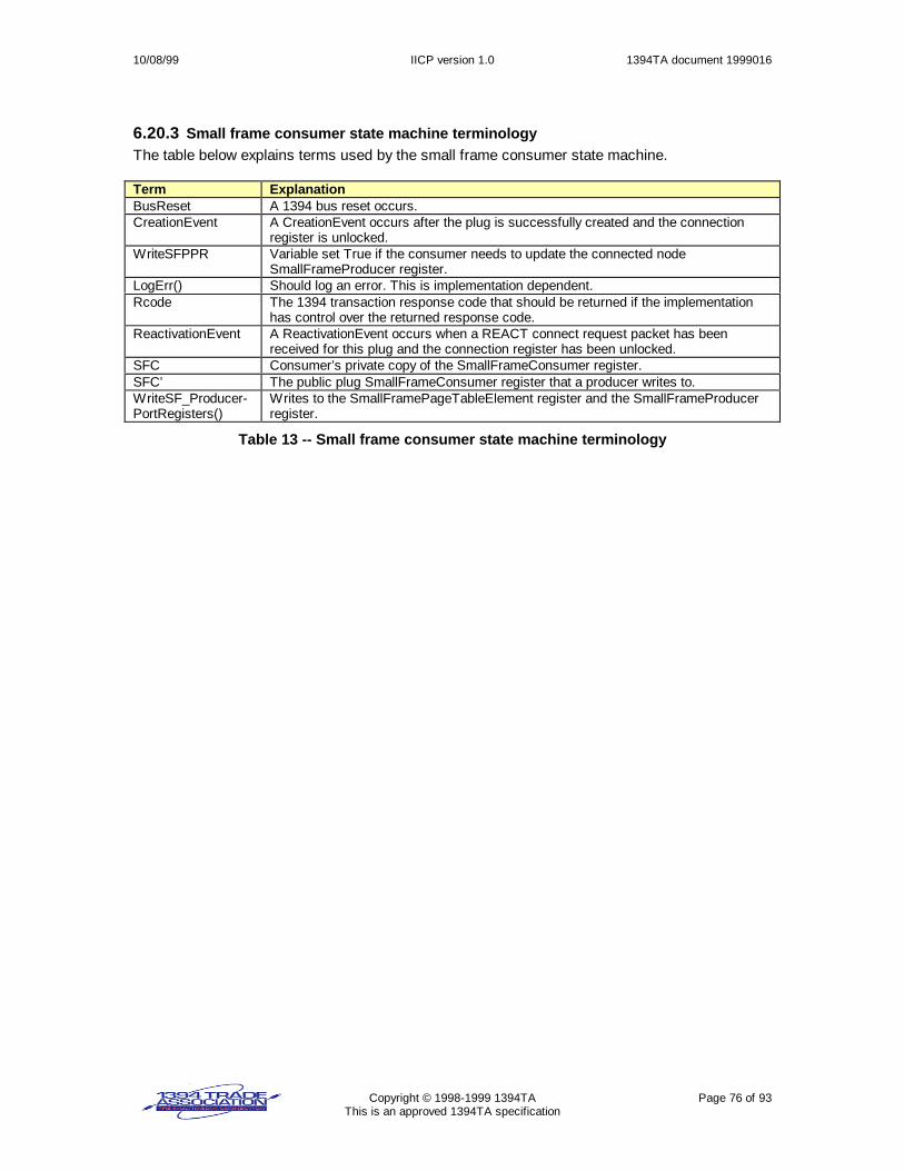
10/08/99 IICP version 1.0 1394TA document 1999016
Copyright © 1998-1999 1394TA Page 76 of 93This is an approved 1394TA specification
6.20.3 Small frame consumer state machine terminologyThe table below explains terms used by the small frame consumer state machine.
Term ExplanationBusReset A 1394 bus reset occurs.CreationEvent A CreationEvent occurs after the plug is successfully created and the connection
register is unlocked.WriteSFPPR Variable set True if the consumer needs to update the connected node
SmallFrameProducer register.LogErr() Should log an error. This is implementation dependent.Rcode The 1394 transaction response code that should be returned if the implementation
has control over the returned response code.ReactivationEvent A ReactivationEvent occurs when a REACT connect request packet has been
received for this plug and the connection register has been unlocked.SFC Consumer’s private copy of the SmallFrameConsumer register.SFC’ The public plug SmallFrameConsumer register that a producer writes to.WriteSF_Producer-PortRegisters()
Writes to the SmallFramePageTableElement register and the SmallFrameProducerregister.
Table 13 -- Small frame consumer state machine terminology

10/08/99 IICP version 1.0 1394TA document 1999016
Copyright © 1998-1999 1394TA Page 77 of 93This is an approved 1394TA specification
6.20.4 Small frame consumer state machineConditionStfate Transi-
tion ActionNew state
BusReset || valid FREE request packet is received for this plugTX0aFree consumer port resources;
Exit
CreationEvent received from connection client state machine.
CSF0: newInitialize consumerport.SFC = 0;WriteSFPPR = T;
TX0b CSF1
BusResetTX1aRestoreState=CSF1
CSF3
A valid STOP request packet is received for this plug.TX1b CSF4
WriteSF_ProducerPortRegisters() failsTX1cLogErr();
CSF4
SFC’ updated && SFC’.sc == SFC.scTX1dIgnore update; Rcode = resp_complete
CSF1
SFC’ updated && SFC’.mode == 1 (SFB_FULL)TX1eSFC=SFC’; WriteSFPPR = T;
CSF2
SFC’ updatedTX1fLogErr(); ignore update; Rcode = resp_data_err
CSF1
Small frame content received.
CSF1:consumeIf ( WriteSFPPR ){WriteSF_ProducerPortRegisters(SFP.sc=~SFC.sc);WriteSFPPR=F;}
Wait forSmallFrame-Consumer registerupdate.
TX1gFrame received indication sent to higher layer.
CSF1
BusResetTX2aRestoreState=CSF2
CSF3
A valid STOP request packet is received for this plug.TX2b CSF4
Small frame segment buffer available
CSF2:Wait for a smallframe segmentbuffer to beavailable TX2c CSF1
BusResetTX3a CSF3
A valid STOP request packet is received for this plug.TX3b CSF4
ReactivationEvent received from connection client state machineTX3c RestoreState
SFC’ updated || (small frame received)
CSF3:deactivated
TX3dLogErr(); Ignore update; Rcode = resp_conflict_err;
CSF3
A FREE request packet is received || BusResetCSF4:waitFREE TX4aFree consumer port resources
Exit
Figure 64 - Small frame consumer state machine
State CSF0. This is the initial small frame consumer state machine state when a plug is created.Variable SFC is set to 0 and variable WriteSFPPR is set true.TransitionTX0a. A FREE request packet is received for this plug, or a bus reset occurs. Anyresources associated with the consumer port are freed. The consumer state machine terminates.Transition TX0b. The connection register is unlocked, allowing consumer activity to commence.A consumer may wait for a read request from a higher layer before transitioning to the next state.
State CSF1. Upon entry, if WriteSFPPR is true, the consumer writes to the producer’sSmallFrameProducer and, if necessary, the SmallFramePageTableElement registers at this timeto allow the producer to begin a small frame transfer. The consumer writes to the connected nodeso that SmallFrameProducer.sc-bit is set to the complement of the consumer’sSmallFrameConsumer.sc bit The consumer waits for small frames and/or aSmallFrameConsumer register update.Transition TX1a. A bus reset occurs.Transition TX1b. A valid STOP request is received for this plug.

10/08/99 IICP version 1.0 1394TA document 1999016
Copyright © 1998-1999 1394TA Page 78 of 93This is an approved 1394TA specification
Transition TX1c. WriteSF_ProducerPortRegisters fails. An error should be logged.Transition TX1d. A SmallFrameConsumer update occurs, but the sc-value is incorrect. Thisupdate is ignored. A response code = resp_complete should be returned.
Transition TX1e. A SmallFrameConsumer update occurs and the new value of theSmallFrameConsumer.mode-bit is set to 1 indicate the small frame consumer segment buffer isexhausted. The consumer copies the new SmallFrameConsumer value. Variable WriteSFPPR isset true.Transition TX1f. A SmallFrameConsumer update occurs and all of the above conditions testedfalse. An error should be logged. The update is ignored. A response code = resp_data_err shouldbe returned.Transition TX1g. A small frame is received. A frame-received indication shall be sent to a higherlayer.
State CSF2. The consumer waits for an available small frame segment buffer.Transition TX2a. A bus reset occurs.Transition TX2b. A valid STOP request packet is received.Transition TX2c. A small frame segment buffer becomes available.
State CSF3. This is the deactivated state. The consumer state machine waits for a REACTpacket to be sent.Transition TX3a. A bus reset occurs.Transition TX3b. A valid STOP request packet is received.Transition TX3c. A ReactivationEvent for this plug is received from the connection client statemachine.Transition TX3d. A SmallFrameConsumer update occurs or a small frame is received. An errorshould be logged. The plug activity should be ignored. A response code = resp_conflict_errshould be returned.
State CSF4. The consumer state machine waits for a FREE packet to be received.Transition TX4a. A bus reset occurs or a FREE packet is received.

10/08/99 IICP version 1.0 1394TA document 1999016
Copyright © 1998-1999 1394TA Page 79 of 93This is an approved 1394TA specification
6.21 Producer state machinesThe producer function is broken up into 2 state machines – one for handling large frames and onefor handling small frames.
6.21.1 Large frame producer state machine terminology
Term ExplanationBusReset A 1394 bus reset occurs.fp Pointer to application data structure returned from WaitForLargeFrameContent(),
WaitForSmallFrameContent().fp->data = pointer to data bufferfp->SF = TRUE if fp->data represents all of a frame and it will fit and be transmitted in asingle 1394 write request.fp->MODE = LAST if fp->data represents last part of a complete framefp->MODE = MORE if fp->data does not represent the last part of a frame.fp->MODE = TRUNC if fp->data represents the end of a truncated frame.fp->size = size (in bytes) for fp->data buffer to be sent.fp->residue = remaining number of bytes to send
FutureLFC A producer variable holding a LargeFrameConsumer value to be written later to theLargeFrameConsumer register on the connected node.
LF_offset Large frame buffer offset. The producer uses this to keep track of the total number of bytessent to the consumer’s large frame buffer space specified in the PageTableElement[]registers.
LF_PTE Current LargeFramePageTableElement[] register in use.LF_PTE_offset Number of bytes sent to the space in the current LargeFramePageTableElement.LFP Producer’s private copy of LargeFrameProducer register.LFP’ The public LargeFrameProducer register that a consumer writes to.LogErr() Should log an error. This is implementation dependent.Rcode The 1394 transaction response code that should be returned if the implementation has
control over the returned response code.ReactivationEvent A ReactivationEvent occurs when a REACT connection request is received for the plug and
the connection register has been unlocked.RestoreState Variable holding the producer state machine state prior to bus reset.WaitForLargeFrame-Content()
WaitForLargeFrameContent() waits for new large frame content to write. The amount offrame content buffered is implementation dependent. If WaitForLargeFrameContent() iscalled and there is still some residual frame content to send (fp->residue != 0)WaitForLargeFrameContent() returns immediately so the residue is sent.WaitForLargeFrameContent() returns if a fp->MODE == LAST or fp->MODE == TRUNCindication is received, even if there is no frame content to be sent.
WriteLargeFrame(fp, PTE, offset, nbytes);
Writes large frame content to the space described in the LargeFramePageTableElement[]register array. The fp variable points to the frame content. Variable PTE is thePageTableElement register. Variable offset is the offset from the currentLargeFramePageTableElement destination_offset where writes are to begin. Variable nbytesspecifies the number of bytes to write.
WriteLFC() Write to the connected node LargeFrameConsumer register.
Table 14 -- Large frame producer state machine terminology

10/08/99 IICP version 1.0 1394TA document 1999016
Copyright © 1998-1999 1394TA Page 80 of 93This is an approved 1394TA specification
6.21.2 Large frame producer state machine, states LFP0 – LFP4ConditionState Tran-
sition ActionNew state
LFP0: new TX0aLFP = 0
LFP1
BusResetTX1aRestoreState=LFP1;
LFP5
A valid STOP request packet is received for this plug.TX1b LFP6
(LFP’ updated && LFP’.sc == LFP.sc)TX1cIgnore update; Rcode = resp_complete
LFP1
LFP’ updated && (LFP’.run == 1) && (LFP’count > 0)TX1dLFP = LFP’; LF_offset = 0; LF_PTE = LargeFramePageTableElement[0];LF_PTE_offset = 0;Rcode = resp_complete
LFP2
LFP’ updated and all above conditions evaluated false
LFP1:Wait forLargeFrame-Producer update
TX1eLogErr(); ignore update; Rcode = resp_type_error
LFP1
BusResetTX2aRestoreState=LFP2;
LFP5
A valid STOP request packet is received for this plug.TX2b LFP6
Large frame write request received&& LF_PTE_offset + fp->residue > LF_PTE.length
TX2c
PTE = LF_PTE, offset = LF_PTE_offset;nbytes = LF_PTE.length – LF_PTE_offset
LFP3
Large frame write request receivedTX2dPTE=LF_PTE; offset=LF_PTE_offset; nbytes=fp->residue
LFP3
LFP’ updated
LFP2:WaitForLarge-FrameContent()
TX2eLogErr(); Ignore update; Rcode = resp_type_error;
LFP2
BusResetTX3aRestoreState=LFP3;
LFP5
A valid STOP request packet is received for this plug.TX3b LFP6
WriteLargeFrame() failsTX3c LFP6
fp->END_OF_FRAME && fp->residue == 0TX3dFutureLFC.sc=LFP.sc; FutureLFC.mode=LAST;FutureLFC.count=LF_offset; Indication( frame sent );
LFP4
LF_offset == LFP.count && fp->residueTX3eFutureLFC.sc=LFP.sc; FutureLFC.mode=MORE;FutureLFC.count=LF_offset;
LFP4
fp->residueTX3fLF_PTE = next LargeFramePageTableElement; LF_PTE_offset = 0;
LFP2
(LF_offset != LFP.count) && (LF_PTE_offset == LF_PTE.length)TX3gLF_PTE = next LargeFramePageTableElement; LF_PTE_offset = 0;Indication( frame content sent );
LFP2
LF_offset != LFP.countTX3hIndication( frame content sent );
LFP2
WriteLargeFrame() finished and all above conditions evaluated to falseTX3kFutureLFC.sc=LFP.sc; FutureLFC.mode=MORE;FutureLFC.count=LF_offset; Indication( frame content sent );
LFP2
LFP’ updated
LFP3:WriteLarge-Frame( fp, PTE,offset, nbytes);
LF_offset +=nbytes;
LF_PTE_offset+= nbytes;
fp->residue -=nbytes;
TX3mLogErr(); Rcode = resp_type_error
LFP3
Figure 65 -- Large frame producer state machine, states LFP0-LFP3

10/08/99 IICP version 1.0 1394TA document 1999016
Copyright © 1998-1999 1394TA Page 81 of 93This is an approved 1394TA specification
6.21.3 Large frame producer state machine, states LFP4 – LFP7ConditionState Tran-
sition ActionNew state
BusResetTX4aRestoreState=LFP4;
LFP5
A valid STOP request receivedTX4b LFP6
WriteLFC succeedsTX4c LFP1
WriteLFC failsTX4dLogErr();
LFP6
LFP’ updated (before WriteLFC completes)
LFP4:WriteLFC( FutureLFC);
TX4eLogErr(); Rcode = resp_type_error;
LFP4
BusResetTX5a LFP5
A valid STOP request receivedTX5b LFP6
LFP’ updatedTX5cIgnore update; Rcode = resp_complete
LFP5
ReactivationEvent received
LFP5:deactivtdLFP.run = 0;
TX5dLFP.run = 1
RestoreState
BusResetTX6a LFP7
LFP’ updatedTX6bIgnore update; rcode = resp_complete
LFP6
All large frame transfers have stopped
LFP6: Stop
TX6c LFP7
BusReset || Valid FREE packet receivedTX7a Exit
LFP’ updated
LFP7:waitFREE
TX7bIgnore update; rcode = resp_complete
LFP7
Figure 66 -- Large frame producer state machine, states LFP4-LFP7
State LFP0. The initial large frame producer state machine state.Transition TX0a. The producer port is initialized. The LargeFrameProducer register is set tozero.
State LFP1. Producer state machine waits for a LargeFrameProducer register update.Transition TX1a. A bus reset occurs. Variable RestoreState is set to the current state, LFP1.Transition TX1b. A valid STOP request is received.Transition TX1c. An update of the LargeFrameProducer register occurs but the sc-bit value isthe same as the current sc-bit value. A response code = resp_complete should be returned.Transition TX1d. An update of the LargeFrameProducer register occurs and the run-bit is setand the count is > 0. The producer’s private copy of the LargeFrameProducer register is set to theupdated value. Variable LF_PTE is set to LargeFramePageTableElement[0] and variablesLF_offset and LF_PTE_offset are set to 0. A response code = resp_complete should be returned.Transition TX1e. The LargeFrameProducer register has been updated and all above conditionshave tested false. An error should be logged. The update shall be ignored. A response code =resp_type_error should be returned.
State LFP2. State machine waits for large frame content to transfer.Transition TX2a. A bus reset occurs. Variable RestoreState is set to the current state, LFP2.Transition TX2b. A valid STOP request is received.
10/08/99 IICP version 1.0 1394TA document 1999016
Copyright © 1998-1999 1394TA Page 82 of 93This is an approved 1394TA specification
Transition TX2c. A request from a higher layer to transfer large frame content is received andthe frame content will not fit into the current LargeFramePageTableElement[] space. VariablePTE is set to LF_PTE, PTE_offset is set to LF_PTE_offset, and nbytes is set to exactly fill up thecurrent LargeFramePageTableElement[] register.Transition TX2d. A request from a higher layer to transfer large frame content is received andthe frame content will fit into the current LargeFramePageTableElement[] space. Variable PTE isset to LF_PTE, PTE_offset is set to LF_PTE_offset, and nbytes is set so that all of the framecontent is transferred.Transition TX2e. An unexpected LargeFrameProducer register update occurs. An error shouldbe logged. The update shall be ignored. A response code = resp_type_error should be returned.
State LFP3. Upon entry, the state machine writes the frame content. When done, variablesLF_offset and LF_PTE_offset are incremented by the number of bytes sent. Variable fp->residueis reduced by the number of bytes sent.Transition TX3a. A bus reset occurs. Variable RestoreState is set to the current state, LFP3.Transition TX3b. A valid STOP request is received.Transition TX3c. WriteLargeFrame() fails for some reason. An error should be logged.Transition TX3d. WriteLargeFrame() completes and the large frame content sent represents thelast of the frame and there is no more frame content to be sent. Variable FutureLFC.sc is set toLargeFrameProducer.sc. Variable FutureLFC.mode is set to LAST. Variable FutureLFC.count isset to LF_offset. An indication to the higher layer that the frame has been sent.Transition TX3e. WriteLargeFrame() completes, all above conditions evaluated false, and thereis more large frame content to be sent, but the space described by theLargeFramePageTableElement[] registers is exhausted. Variable FutureLFC.sc is set toLargeFrameProducer.sc. Variable FutureLFC.mode is set to MORE. Variable FutureLFC.count isset to LF_offset.Transition TX3f. WriteLargeFrame() completes, all above conditions evaluated false, and thereis more large frame content to be sent. Variable LF_PTE is set to the next adjacentLargeFramePageTableElement[] register and LF_PTE_offset is set to 0.Transition TX3g. WriteLargeFrame() completes, all above conditions evaluated false, and thereis no space remaining in the space described by the current LargeFramePageTableElement[].Variable LF_PTE is set to the next adjacent LargeFramePageTableElement[] and variableLF_PTE_offset is reset to 0. An indication is returned that the frame content was sent.Transition TX3h. WriteLargeFrame() completes, all above conditions evaluated false, andvariable LF_offset != LF_LFP.count.Transition TX3k. WriteLargeFrame() completes and all above conditions evaluated false. Anindication is returned that the frame content was sent. Variable FutureLFC.sc is set toLargeFrameProducer.sc. Variable FutureLFC.mode is set to MORE. Variable FutureLFC.count isset to LF_offset.Transition TX3m. An unexpected LargeFrameProducer register update occurs. An error shouldbe logged. The update shall be ignored. A response code = resp_type_error should be returned.
State LFP4. Upon entry, the state machine writes to the connected node LargeFrameConsumerregister.Transition TX4a. A bus reset occurs. Variable RestoreState is set to the current state, LFP4.Transition TX4b. A valid STOP request is received.Transition TX4c. WriteLFC() succeeds.Transition TX4d. WriteLFC() fails. An error should be logged.Transition TX4e. An unexpected LargeFrameProducer register update occurs. An error shouldbe logged. The update shall be ignored. A response code = resp_type_error should be returned.
State LFP5. This is the deactivated state. Upon entry, the LFP.sc and LFP.run bits are cleared.Transition TX5a. A bus reset occurs.Transition TX5b. A valid STOP request is received.Transition TX5c. An unexpected LargeFrameProducer register update occurs. An error shouldbe logged. The update shall be ignored. A response code = resp_type_error should be returned.

10/08/99 IICP version 1.0 1394TA document 1999016
Copyright © 1998-1999 1394TA Page 83 of 93This is an approved 1394TA specification
Transition TX5d. A ReactivationEvent for this plug is received from the connection client statemachine.
State LFP6. The producer shall not initiate the sending of any more frame content. The producershould abort any frame content transfers that are queued.Transition TX6a. A bus reset occurs.Transition TX6b. A LargeFrameProducer register update occurs.Transition TX6c. All frame transfers have stopped.
State P7. The producer state machine waits for a FREE packet to be received.Transition TX7a. A bus reset occurs or a FREE packet is received. The producer frees producerport resources. The state machine terminates.Transition TX7b. An update of the LargeFrameProducer register occurs. The update is ignored.A response code = resp_complete should be returned.

10/08/99 IICP version 1.0 1394TA document 1999016
Copyright © 1998-1999 1394TA Page 84 of 93This is an approved 1394TA specification
6.21.4 Small frame producer state machine terminologyThe table below explains terms used by the small frame producer state machine.
Term ExplanationBusReset A 1394 bus reset occurs.Fp Pointer to application data structure returned from WaitForLargeFrameContent(),
WaitForSmallFrameContent().fp->data = pointer to data bufferfp->SF = TRUE if fp->data represents all of a frame and it will fit and be transmitted in asingle 1394 write request.fp->MODE = LAST if fp->data represents last part of a complete framefp->MODE = MORE if fp->data does not represent the last part of a frame.fp->MODE = TRUNC if fp->data represents the end of a truncated frame.fp->size = size (in bytes) for fp->data buffer to be sent.fp->residue = remaining number of bytes to send
LogErr() Should log an error. This is implementation dependent.NF Number of small frames sent since last SmallFrameProducer register updateRcode The response code that should be returned if the implementation has control over the
returned response code.ReactivationEvent A ReactivationEvent occurs when a REACT connection request is received for the plug and
the connection register has been unlocked.RestoreState Variable holding the producer state machine state prior to bus reset.SF_offset Small frame space offset. The producer uses this to keep track of how many bytes have
been sent to the consumer’s small frame space.SF_PTE SmallFramePageTableElement registerSFP Producer’s private copy of the SmallFrameProducer register.SFP’ The public SmallFrameProducer register that a consumer writes to.WaitForSmallFrame-Content()
WaitForSmallFrameContent() waits, if necessary, for new small frame content to write. If abus reset occurs after WaitForSmallFrameContent() returned with a small frame to send butbefore the small frame was sent, WaitForSmallFrameContent() returns immediately so thesmall frame is sent.
WriteSFC() Write to the connected node SmallFrameConsumer register.WriteSmallFrame(fp,offset, nbytes)
Writes a small frame to the space described by the SmallFramePageTableElement. The fpvariable points to the frame content. Variable PTE is the PageTableElement register.Variable offset is the offset from the PageTableElement destination_offset where writes areto begin. Variable nbytes specifies the number of bytes to write.
Table 15 -- Small frame producer state machine terminology

10/08/99 IICP version 1.0 1394TA document 1999016
Copyright © 1998-1999 1394TA Page 85 of 93This is an approved 1394TA specification
6.21.5 Small frame producer state machine, states SFP0 – SFP4ConditionState Tran-
sition ActionNew state
SFP0: new TX0aSFP = 0
SFP1
BusResetTX1aRestoreState=SFP1;
SFP5
A valid STOP request packet is received for this plug.TX1b SFP6
(SFP’ updated && SFP’.sc == SFP.sc)TX1cIgnore update; Rcode = resp_complete
SFP1
SFP’ updated && (SFP’.run == 1) && (SFP’count > 0)TX1dSFP = SFP’; SF_offset = 0; SF_PTE = SmallFramePageTableElement;NF = 0;Rcode = resp_complete
SFP2
SFP’ updated and all above conditions evaluated false
SFP1:Wait forSmallFrame-Producer update
TX1eLogErr(); ignore update; Rcode = resp_type_error
SFP1
BusResetTX2aRestoreState=SFP2;
SFP5
A valid STOP request packet is received for this plug.TX2b SFP6
Small frame write request received&& SF_offset + fp->residue > SF_PTE..length
TX2c SFP4
Small frame write request receivedTX2dPTE=SF_PTE; offset=SF_offset; nbytes=fp->residue
SFP3
SFP’ updated
SFP2:WaitForSmall-FrameContent()
TX2eLogErr(); Ignore update; Rcode = resp_type_error;
SFP2
BusResetTX3aRestoreState=SFP3;
SFP5
A valid STOP request packet is received for this plug.TX3b SFP6
WriteSmallFrame() failsTX3c SFP6
WriteSmallFrame() completes &&(SF_offset == SF_PTE.length) || (NF == SFP.maxSmallFrameCount)
TX3d
Indication( small frame sent );
SFP4
WriteSmallFrame() completesTX3e SFP2
SFP’ updated
SFP3:WriteSmall-Frame( fp, PTE,offset, nbytes);
SF_offset +=nbytes;
fp->residue -=nbytes;
NF++;
TX3fLogErr(); Rcode = resp_type_error
SFP3
Figure 67 -- Small frame producer state machine, states SFP0-SFP3

10/08/99 IICP version 1.0 1394TA document 1999016
Copyright © 1998-1999 1394TA Page 86 of 93This is an approved 1394TA specification
6.21.6 Small frame producer state machine, states SFP4 – SFP7ConditionState Tran-
sition ActionNew state
BusResetTX4aRestoreState=SFP4;
SFP5
A valid STOP request receivedTX4b SFP6
WriteSFC succeedsTX4c SFP1
WriteSFC failsTX4dLogErr();
SFP6
SFP’ updated (before WriteSFC completes)
SFP4:WriteSFC( SFC.sc=SFP.sc, SFC.mode=1 );
TX4eLogErr(); Rcode = resp_type_error;
SFP4
BusResetTX5a SFP5
A valid STOP request receivedTX5b SFP6
SFP’ updatedTX5cIgnore update; Rcode = resp_complete
SFP5
ReactivationEvent received
SFP5:deactivtdSFP.run = 0;
TX5dSFP.run = 1;
RestoreState
BusResetTX6a SFP7
SFP’ updatedTX6bIgnore update; rcode = resp_complete
SFP6
All Small frame transfers have stopped
SFP6: Stop
TX6c SFP7
BusReset || valid FREE packet receivedTX7a Exit
SFP’ updated
SFP7:waitFREE
TX7bIgnore update; rcode = resp_complete
SFP7
Figure 68 -- Small frame producer state machine, states SFP4-SFP7
State SFP0. The initial Small frame producer state machine state.Transition TX0a. The producer port is initialized. The SmallFrameProducer register is set tozero.
State SFP1. Producer state machine waits for a SmallFrameProducer register update.Transition TX1a. A bus reset occurs. Variable RestoreState is set to the current state, SFP1.Transition TX1b. A valid STOP request is received.Transition TX1c. An update of the SmallFrameProducer register occurs but the sc-bit value isthe same as the current sc-bit value. A response code = resp_complete should be returned.Transition TX1d. An update of the SmallFrameProducer register occurs and the run-bit is setand the count is > 0. The producer’s private copy of the SmallFrameProducer register is set to theupdated value. Variable SF_PTE is set to SmallFramePageTableElement[0] and variablesSF_offset and SF_PTE_offset are set to 0. A response code = resp_complete should bereturned.Transition TX1e. The SmallFrameProducer register has been updated and all above conditionshave tested false. An error should be logged. The update shall be ignored. A response code =resp_type_error should be returned.
State SFP2. State machine waits for Small frame content to transfer.Transition TX2a. A bus reset occurs. Variable RestoreState is set to the current state, SFP2.

10/08/99 IICP version 1.0 1394TA document 1999016
Copyright © 1998-1999 1394TA Page 87 of 93This is an approved 1394TA specification
Transition TX2b. A valid STOP request is received.Transition TX2c. A request from a higher layer to transfer a small frame is received and theframe content will not fit into the space described by the SmallFramePageTableElement. None ofthe small frame content is transferred.Transition TX2d. A request from a higher layer to transfer a small frame is received and theframe content will fit into the space described by the SmallFramePageTableElement. VariablePTE is set to SF_PTE, PTE_offset is set to SF_offset, and nbytes is set so that all of the framecontent is transferred.Transition TX2e. An unexpected SmallFrameProducer register update occurs. An error shouldbe logged. The update shall be ignored. A response code = resp_type_error should be returned.
State SFP3. Upon entry, the state machine writes the frame content. When done, variablesSF_offset and SF_PTE_offset are incremented by the number of bytes sent. Variable fp->residueis reduced by the number of bytes sent.Transition TX3a. A bus reset occurs. Variable RestoreState is set to the current state, SFP3.Transition TX3b. A valid STOP request is received.Transition TX3c. WriteSmallFrame() fails for some reason. An error should be logged.Transition TX3d. WriteSmallFrame() completes and the small frame space is exhausted or themaximum number of small frames has been sent. An indication to the higher layer that the framehas been sent.Transition TX3e. WriteSmallFrame() completes and all above conditions evaluated false.Transition TX3f. An unexpected SmallFrameProducer register update occurs. An error should belogged. The update shall be ignored. A response code = resp_type_error should be returned.
State SFP4. Upon entry, the state machine writes to the connected node SmallFrameConsumerregister.Transition TX4a. A bus reset occurs. Variable RestoreState is set to the current state, SFP4.Transition TX4b. A valid STOP request is received.Transition TX4c. WriteSFC() succeeds.Transition TX4d. WriteSFC() fails. An error should be logged.Transition TX4e. An unexpected SmallFrameProducer register update occurs. An error shouldbe logged. The update shall be ignored. A response code = resp_type_error should be returned.
State SFP5. This is the deactivated state. Upon entry, the SFP.sc and SFP.run bits are cleared.Transition TX5a. A bus reset occurs.Transition TX5b. A valid STOP request is received.Transition TX5c. An unexpected SmallFrameProducer register update occurs. An error shouldbe logged. The update shall be ignored. A response code = resp_type_error should be returned.Transition TX5d. A ReactivationEvent for this plug is received from the connection client statemachine.
State SFP6. The producer shall not initiate the sending of any more small frames. The producershould abort any frame transfers that are queued.Transition TX6a. A bus reset occurs.Transition TX6b. A SmallFrameProducer register update occurs.Transition TX6c. All frame transfers have stopped.
State P7. The producer state machine waits for a FREE packet to be received.Transition TX7a. A bus reset occurs or a FREE packet is received. The producer frees producerport resources. The state machine terminates.Transition TX7b. An update of the SmallFrameProducer register occurs. The update is ignored.A response code = resp_complete should be returned.

10/08/99 IICP version 1.0 1394TA document 1999016
Copyright © 1998-1999 1394TA Page 88 of 93This is an approved 1394TA specification
7. IICP services (informative)IICP layer services are provided at the interface between the IICP layer and higher layers.
Row Service Layer communicated with Purpose of service1 IICP control request From higher layer This service performs one or more of the
following:• Initialize the IICP layer.• Configure the IICP layer.
2 IICP open request From higher layer Causes a connection sequence to be issued.3 IICP close request From higher layer Causes a connection to be torn down and freed.4 IICP write data frame
requestFrom higher layer Causes a data frame to be sent.
5 IICP write controlframe request
From higher layer Causes a control frame to be sent.
6 IICP read data framerequest
From higher layer Causes an update of the data portProducerMode register.
7 IICP CREQ1 indication To higher layer Indicate the reception of a CREQ1 packet fromanother node..
8 IICP connectionestablished indication
To higher layer Indicate the completion of a connectionsequence initiated by another node.
9 IICP stop indication To higher layer Indicate the reception of a STOP packet10 IICP error indication To higher layer Indicate an IICP layer error or lower level
protocol error.11 IICP control frame
received indicationTo higher layer Indicate reception and convey contents of control
frame to higher layer.
7.1 IICP control requestThe higher layer uses this service to perform one or more of the following:1. Initialize the IICP layer.2. Configure the IICP layer.
Ever power-on sequence should result in control requests to initialize the layer and to configurethe IICP layer.
7.1.1 Initialization of IICP layerThis operation results in the initialization of the connection manager state machine (if theimplementation can perform as a connection manager) and the connection client state machine.This operation would also initialize the connection lock register and map the 512-byte connectionregister to 1394 space.
7.1.2 Configure the IICP layerThis operation would communicate any tunable parameters to the IICP layer. Examples oftunable parameters are:1. Maximum and minimum sizes for buffers.2. Maximum sizes for scatter/gather page tables.
This would also allow registration of callback functions for certain events that a higher layer wouldbe interested in knowing about. Suggested callback functions an implementation may provideare:1. IICP_CREQ1_callback (… )2. IICP_connectionEstablished_callback (… )3. IICP_STOP_callback (… )4. IICP_err_callback (… )

10/08/99 IICP version 1.0 1394TA document 1999016
Copyright © 1998-1999 1394TA Page 89 of 93This is an approved 1394TA specification
7.1.2.1 IICP_CREQ1_callback (… )Notifies higher layer of a new connection. The following parameters from the CREQ1 packet arecommunicated to the higher layer.1. CommandSet2. ConnectionParameters
The higher layer may return the following information to the IICP layer:1. Acceptance or rejection of the connection request.2. Whether the connected node is required to write sequentially.3. The size of data frames that the higher layer may produce.4. The size of control frames that the higher layer may produce.
After receiving the information from the higher layer, the IICP layer formulates the connectionresponse (CRESP1).
If the higher layer has not registered an IICP_CREQ1_callback(… ), the IICP layer should proceedwith default parameters.
If the higher layer has registered an IICP_CREQ1_callback(… ) but only returns partialinformation, the IICP layer should proceed with default parameters as appropriate.
7.1.2.2 IICP_connectionEstablished_callback (… )Notifies higher layer of the completion of a connection sequence initiated by another node. Thisservice communicates to a higher layer that it is now permissible to perform reads and writesthrough this new connection. The following parameters from the CREQ2 packet is communicatedto the higher layer.
1. The data frame size from the connected node.2. The control frame size from the connected node.3. Whether the connected node requires sequential writes.4. A handle to the newly created connection.
7.1.2.3 IICP_STOP_callback (… )Notifies higher layer of the cessation of plug activity.
7.1.2.4 IICP_err_callback (… )Notifies higher layer of an IICP error or lower protocol error. A higher layer may log the error to afile, to an I/O port for printing, or to a display. An example of the use of IICP_err_callback() is if aplug fails reactivation after a bus reset.
7.2 IICP open requestThis service, available on nodes that have connection manager capability, issues a connectionsequence and establishes a plug connection between two IICP devices. The higher layerprovides the following information so the IICP layer can perform the request:1. command_set_spec_id, command_set, and command_set_details.2. connectionParameters.3. Some form of node identification for the node to be connected.4. The data frame size.5. The control frame size.6. Whether sequential writes are required.
When the connection sequence has completed, the following information is provided to the higherlayer:1. Success or failure of establishing the connection.

10/08/99 IICP version 1.0 1394TA document 1999016
Copyright © 1998-1999 1394TA Page 90 of 93This is an approved 1394TA specification
2. Whether sequential writes are required when writing to the connected node.3. The size of data frames from the connected node.4. The size of control frames from the connected node.
7.3 IICP close requestThis service, available on nodes that have connection manager capability, issues a connectionsequence to stop a plug.
7.4 IICP write data frame requestThis service results in a data frame or a part of a data frame being sent to the connected node.Example, informative, pseudo-code is shown below.
IICP_write(…, bool END_OF_FRAME, …){ bool sent = false; bool isSmallFrame = true;
if ( request size > 512 bytes || request does not represent complete frame ) { isSmallFrame = false; } if ( small frame producer state == SFP2 && isSmallFrame && END_OF_FRAME ) { sent = SmallFrameWriteRequest(…); // might not be sent if // not enough space } if ( !sent ) { // send as large frame block until large frame producer state == LFP2; LargeFrameWriteRequest(…); }}
7.5 IICP write control frame requestThis service results in a control frame or part of a control frame being sent to the connected node.This service may provide a mechanism for higher layer protocols (for example, IICP488) to sendasynchronous stream trigger packets.
7.6 IICP read data frame requestThis service results in the programming of the data port ProducerMode register on the connectednode. The connected node may then begin sending data frame(s).
The IICP layer blocks until the read request is satisfied. The criteria for returning from a readrequest are implementation and higher level protocol dependent.
7.7 IICP CREQ1 indicationIf a callback has been registered (see the IICP control service), the callback function is called withimplementation-dependent parameters.
7.8 IICP connection established indicationIf a callback has been registered (see the IICP control service), the callback function is called withimplementation-dependent parameters.

10/08/99 IICP version 1.0 1394TA document 1999016
Copyright © 1998-1999 1394TA Page 91 of 93This is an approved 1394TA specification
7.9 IICP stop indicationIf a callback has been registered (see the IICP control service), the callback function is called withimplementation-dependent parameters.
7.10 IICP err indicationIf a callback has been registered (see the IICP control service), the callback function is called withimplementation-dependent parameters.
7.11 IICP control frame received indicationThis indication occurs when an IICP control frame is received. This indication may be a callbackfunction that has been set up by the higher layer. A callback may have been set up in either ofthe following ways:1) Via a parameter in the IICP open request.2) Via the IICP connection established indication callback parameters.

10/08/99 IICP version 1.0 1394TA document 1999016
Copyright © 1998-1999 1394TA Page 92 of 93This is an approved 1394TA specification
8. Error recoveryThis section further enumerates methods and practices to ensure error free IICPcommunications.
8.1 Application-level retriesThe resources associated with plug-visible addresses are designed to be idempotent, in that theeffects of single and duplicated writes are the same. For this reason, transaction faults observedby the requester (but not necessarily observed the responder) can be safely retried by the plug-level application.
1394 transaction-level errors expected to be retried include the following:• Response timeout. The response does not return within the SPLIT_TIMEOUT specified
timeout.• Response errors. The response returns with either of the following response code (rcode)
values:1) resp_data_error. This can be indicative of a transient transmission error.2) resp_conflict_error. This can be indicative of a transient bridge congestion condition.
The same expectations apply to unified transactions completed with ack_data_error orack_conflict_error indications (rather than resp_data_error or resp_conflict_error).
If another transaction-level response is returned, or if a reasonable number of retries fail, an errorshould be logged. The relevant state machine shows the behavior to follow when an error occurs.
8.2 1394 bus resets1394 bus resets will occur on busses when devices are powered on and off or when 1394 cablingis changed. After a bus reset, a node shall deactivate all IICP connections. A reactivation requestfrom the node that instantiated the connection is required to reactivate the connection. Seesection 6.13 above.
8.2.1 Bus reset while connection registers are lockedAny plug and/or plug resources in the process of being created may be freed. After a bus reset,the connection manager is required to send all connection requests over again.
8.2.2 Bus reset during updates of plug fieldsA bus reset may occur while a node is updating the public memory plug fields of another node.Any bus reset that occurs prior to a final ack complete shall result in the update being re-sent.
8.2.3 Bus reset while transferring dataA 1394 bus reset can occur while transferring data. When this occurs, an IICP plug shall go to thedeactivated state until a reactivation occurs. Following a reactivation (of both nodes involved inthe connection), any data that was being sent that was interrupted shall be resent.
To further clarify, after a reactivation of both sides of a connection, a producer shall retransmit alloutstanding write requests that were in the process of being written to a consumer. A transactionshall be considered outstanding if a write response has not been received and an ack-completesuccessfully sent from the producer to the consumer.
Consumers shall be tolerant of receiving duplicate write packets.

10/08/99 IICP version 1.0 1394TA document 1999016
Copyright © 1998-1999 1394TA Page 93 of 93This is an approved 1394TA specification
8.2.4 Duplicate writesIf a consumer receives a write with a destination offset identical to a previous write that wassuccessfully processed, the consumer shall accept the packet and either discard the redundantwrite or process the write.