1398-2.1(899), 1398 ultra series 230v brushless...
TRANSCRIPT
1398 ULTRA Series™ 230V Brushless Servo Motors
Product Data
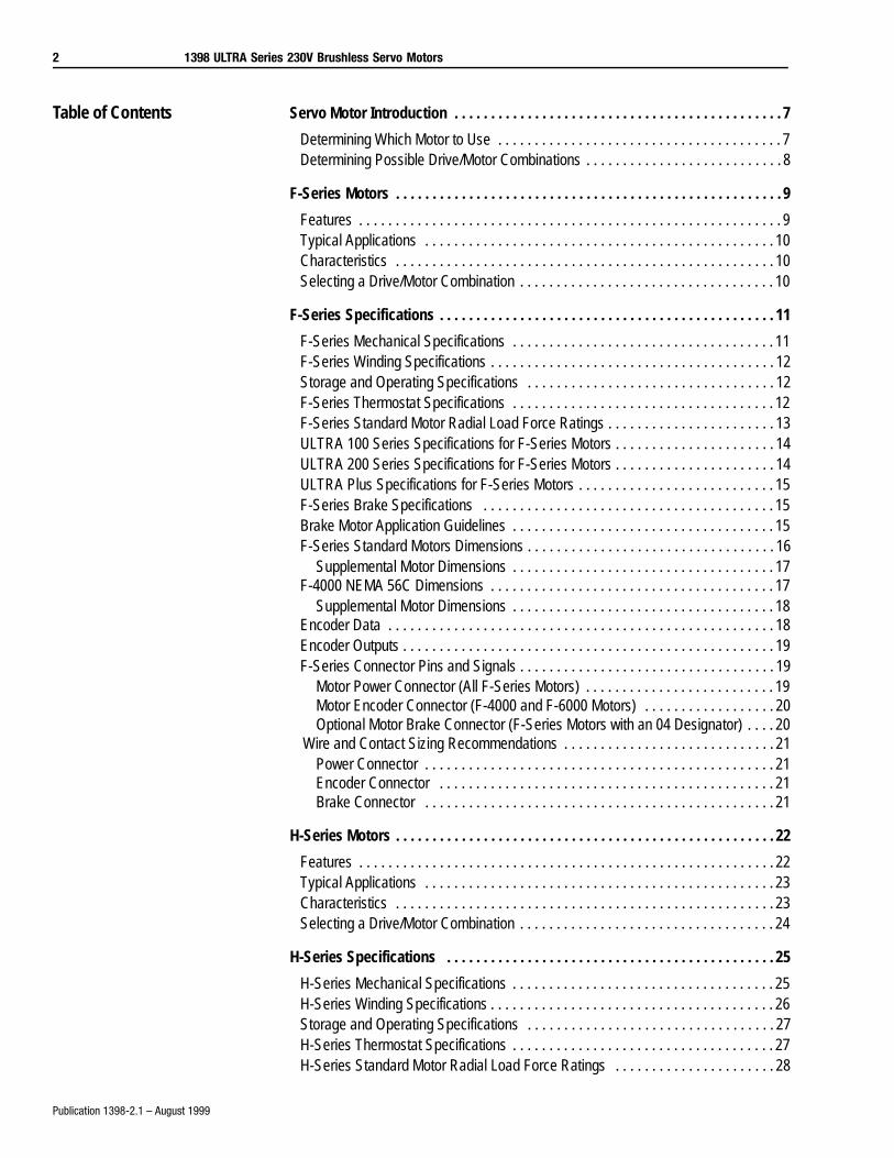
This publication provides product information for the 0.17 to 50 N-m (1.5 to 450 lb-in.) 1398 ULTRA Series™ 230V, Low-to-Medium Inertia, Brushless Servo Motors. This publication includes:
• Detailed lists of the features and options available for 1398 ULTRA Series 230V, Low-to-Medium Inertia, Brushless Servo Motors
• Performance data and speed-torque curves for the entire 1398 ULTRA Series Servo motor family
• Servo motor dimensions
2 1398 ULTRA Series 230V Brushless Servo Motors
Publication 1398-2.1 – August 1999
Table of Contents Servo Motor Introduction . . . . . . . . . . . . . . . . . . . . . . . . . . . . . . . . . . . . . . . . . . . . . 7
Determining Which Motor to Use . . . . . . . . . . . . . . . . . . . . . . . . . . . . . . . . . . . . . . . 7Determining Possible Drive/Motor Combinations . . . . . . . . . . . . . . . . . . . . . . . . . . . 8
F-Series Motors . . . . . . . . . . . . . . . . . . . . . . . . . . . . . . . . . . . . . . . . . . . . . . . . . . . . . 9
Features . . . . . . . . . . . . . . . . . . . . . . . . . . . . . . . . . . . . . . . . . . . . . . . . . . . . . . . . . . 9Typical Applications . . . . . . . . . . . . . . . . . . . . . . . . . . . . . . . . . . . . . . . . . . . . . . . . 10Characteristics . . . . . . . . . . . . . . . . . . . . . . . . . . . . . . . . . . . . . . . . . . . . . . . . . . . . 10Selecting a Drive/Motor Combination . . . . . . . . . . . . . . . . . . . . . . . . . . . . . . . . . . . 10
F-Series Specifications . . . . . . . . . . . . . . . . . . . . . . . . . . . . . . . . . . . . . . . . . . . . . . 11
F-Series Mechanical Specifications . . . . . . . . . . . . . . . . . . . . . . . . . . . . . . . . . . . . 11F-Series Winding Specifications . . . . . . . . . . . . . . . . . . . . . . . . . . . . . . . . . . . . . . . 12Storage and Operating Specifications . . . . . . . . . . . . . . . . . . . . . . . . . . . . . . . . . . 12F-Series Thermostat Specifications . . . . . . . . . . . . . . . . . . . . . . . . . . . . . . . . . . . . 12F-Series Standard Motor Radial Load Force Ratings . . . . . . . . . . . . . . . . . . . . . . . 13ULTRA 100 Series Specifications for F-Series Motors . . . . . . . . . . . . . . . . . . . . . . 14ULTRA 200 Series Specifications for F-Series Motors . . . . . . . . . . . . . . . . . . . . . . 14ULTRA Plus Specifications for F-Series Motors . . . . . . . . . . . . . . . . . . . . . . . . . . . 15F-Series Brake Specifications . . . . . . . . . . . . . . . . . . . . . . . . . . . . . . . . . . . . . . . . 15Brake Motor Application Guidelines . . . . . . . . . . . . . . . . . . . . . . . . . . . . . . . . . . . . 15F-Series Standard Motors Dimensions . . . . . . . . . . . . . . . . . . . . . . . . . . . . . . . . . . 16
Supplemental Motor Dimensions . . . . . . . . . . . . . . . . . . . . . . . . . . . . . . . . . . . . 17F-4000 NEMA 56C Dimensions . . . . . . . . . . . . . . . . . . . . . . . . . . . . . . . . . . . . . . . 17
Supplemental Motor Dimensions . . . . . . . . . . . . . . . . . . . . . . . . . . . . . . . . . . . . 18Encoder Data . . . . . . . . . . . . . . . . . . . . . . . . . . . . . . . . . . . . . . . . . . . . . . . . . . . . . 18Encoder Outputs . . . . . . . . . . . . . . . . . . . . . . . . . . . . . . . . . . . . . . . . . . . . . . . . . . . 19F-Series Connector Pins and Signals . . . . . . . . . . . . . . . . . . . . . . . . . . . . . . . . . . . 19
Motor Power Connector (All F-Series Motors) . . . . . . . . . . . . . . . . . . . . . . . . . . 19Motor Encoder Connector (F-4000 and F-6000 Motors) . . . . . . . . . . . . . . . . . . 20Optional Motor Brake Connector (F-Series Motors with an 04 Designator) . . . . 20
Wire and Contact Sizing Recommendations . . . . . . . . . . . . . . . . . . . . . . . . . . . . . 21Power Connector . . . . . . . . . . . . . . . . . . . . . . . . . . . . . . . . . . . . . . . . . . . . . . . . 21Encoder Connector . . . . . . . . . . . . . . . . . . . . . . . . . . . . . . . . . . . . . . . . . . . . . . 21Brake Connector . . . . . . . . . . . . . . . . . . . . . . . . . . . . . . . . . . . . . . . . . . . . . . . . 21
H-Series Motors . . . . . . . . . . . . . . . . . . . . . . . . . . . . . . . . . . . . . . . . . . . . . . . . . . . . 22
Features . . . . . . . . . . . . . . . . . . . . . . . . . . . . . . . . . . . . . . . . . . . . . . . . . . . . . . . . . 22Typical Applications . . . . . . . . . . . . . . . . . . . . . . . . . . . . . . . . . . . . . . . . . . . . . . . . 23Characteristics . . . . . . . . . . . . . . . . . . . . . . . . . . . . . . . . . . . . . . . . . . . . . . . . . . . . 23Selecting a Drive/Motor Combination . . . . . . . . . . . . . . . . . . . . . . . . . . . . . . . . . . . 24
H-Series Specifications . . . . . . . . . . . . . . . . . . . . . . . . . . . . . . . . . . . . . . . . . . . . . 25
H-Series Mechanical Specifications . . . . . . . . . . . . . . . . . . . . . . . . . . . . . . . . . . . . 25H-Series Winding Specifications . . . . . . . . . . . . . . . . . . . . . . . . . . . . . . . . . . . . . . . 26Storage and Operating Specifications . . . . . . . . . . . . . . . . . . . . . . . . . . . . . . . . . . 27H-Series Thermostat Specifications . . . . . . . . . . . . . . . . . . . . . . . . . . . . . . . . . . . . 27H-Series Standard Motor Radial Load Force Ratings . . . . . . . . . . . . . . . . . . . . . . 28
1398 ULTRA Series 230V Brushless Servo Motors 3
Publication 1398-2.1 – August 1999
ULTRA 100 Series Specifications for H-Series Motors . . . . . . . . . . . . . . . . . . . . . 29ULTRA 200 Series Specifications for H-Series Motors . . . . . . . . . . . . . . . . . . . . . 30ULTRA Plus Specifications for H-Series Motors . . . . . . . . . . . . . . . . . . . . . . . . . . . 31H-Series Brake Specifications . . . . . . . . . . . . . . . . . . . . . . . . . . . . . . . . . . . . . . . . 31Brake Motor Application Guidelines . . . . . . . . . . . . . . . . . . . . . . . . . . . . . . . . . . . . 32H-Series Standard Motors Dimensions . . . . . . . . . . . . . . . . . . . . . . . . . . . . . . . . . 32H-2000 Motors Dimensions . . . . . . . . . . . . . . . . . . . . . . . . . . . . . . . . . . . . . . . . . . 33H-3000, -4000, -6000, and -8000 Motors Dimensions . . . . . . . . . . . . . . . . . . . . . . 33
Supplemental Motor Dimensions . . . . . . . . . . . . . . . . . . . . . . . . . . . . . . . . . . . . 35H-4000 NEMA 56C Dimensions . . . . . . . . . . . . . . . . . . . . . . . . . . . . . . . . . . . . . . . 35
Supplemental Motor Dimensions . . . . . . . . . . . . . . . . . . . . . . . . . . . . . . . . . . . . 36Encoder Data . . . . . . . . . . . . . . . . . . . . . . . . . . . . . . . . . . . . . . . . . . . . . . . . . . . . . 37Encoder Outputs . . . . . . . . . . . . . . . . . . . . . . . . . . . . . . . . . . . . . . . . . . . . . . . . . . 37H-Series Connector Pins and Signals . . . . . . . . . . . . . . . . . . . . . . . . . . . . . . . . . . 38
Motor Power Connector (All H-Series Motors) . . . . . . . . . . . . . . . . . . . . . . . . . . 38Motor Encoder Connector . . . . . . . . . . . . . . . . . . . . . . . . . . . . . . . . . . . . . . . . . 38Optional Motor Brake Connector . . . . . . . . . . . . . . . . . . . . . . . . . . . . . . . . . . . . 39
Wire and Contact Sizing Recommendations . . . . . . . . . . . . . . . . . . . . . . . . . . . . . 39Power Connector . . . . . . . . . . . . . . . . . . . . . . . . . . . . . . . . . . . . . . . . . . . . . . . . 39Encoder Connector . . . . . . . . . . . . . . . . . . . . . . . . . . . . . . . . . . . . . . . . . . . . . . 40Brake Connector . . . . . . . . . . . . . . . . . . . . . . . . . . . . . . . . . . . . . . . . . . . . . . . . 40
Y-Series Motors . . . . . . . . . . . . . . . . . . . . . . . . . . . . . . . . . . . . . . . . . . . . . . . . . . . . 41
Features . . . . . . . . . . . . . . . . . . . . . . . . . . . . . . . . . . . . . . . . . . . . . . . . . . . . . . . . . 41Typical Applications . . . . . . . . . . . . . . . . . . . . . . . . . . . . . . . . . . . . . . . . . . . . . . . . 42Selecting a Drive/Motor Connection . . . . . . . . . . . . . . . . . . . . . . . . . . . . . . . . . . . . 42
Y-Series Specifications . . . . . . . . . . . . . . . . . . . . . . . . . . . . . . . . . . . . . . . . . . . . . 43
Y-Series Mechanical Specifications . . . . . . . . . . . . . . . . . . . . . . . . . . . . . . . . . . . . 43Y-Series Winding Specifications . . . . . . . . . . . . . . . . . . . . . . . . . . . . . . . . . . . . . . 44Storage and Operating Specifications . . . . . . . . . . . . . . . . . . . . . . . . . . . . . . . . . . 44Brake Motor Application Guidelines . . . . . . . . . . . . . . . . . . . . . . . . . . . . . . . . . . . . 44Y-Series Brake Specifications . . . . . . . . . . . . . . . . . . . . . . . . . . . . . . . . . . . . . . . . 45Y-Series Motor Brake and Shaft Load Data . . . . . . . . . . . . . . . . . . . . . . . . . . . . . . 45ULTRA 100 Series Specifications for Y-Series Motors . . . . . . . . . . . . . . . . . . . . . 46ULTRA 200 Specifications for Y-Series Motors . . . . . . . . . . . . . . . . . . . . . . . . . . . 46Y-Series Standard Motors Dimensions . . . . . . . . . . . . . . . . . . . . . . . . . . . . . . . . . 47
Supplemental Motor Dimensions . . . . . . . . . . . . . . . . . . . . . . . . . . . . . . . . . . . . 48Cable Diameters . . . . . . . . . . . . . . . . . . . . . . . . . . . . . . . . . . . . . . . . . . . . . . . . 48
Encoder Data . . . . . . . . . . . . . . . . . . . . . . . . . . . . . . . . . . . . . . . . . . . . . . . . . . . . . 48Encoder Outputs . . . . . . . . . . . . . . . . . . . . . . . . . . . . . . . . . . . . . . . . . . . . . . . . . . 49Y-Series Connector Pins and Signals . . . . . . . . . . . . . . . . . . . . . . . . . . . . . . . . . . 49
Motor Power Connector (All Y-Series Motors) . . . . . . . . . . . . . . . . . . . . . . . . . . 49Motor Feedback Connector (All Y-Series Motors) . . . . . . . . . . . . . . . . . . . . . . . 50
Wire and Contact Sizing Recommendations . . . . . . . . . . . . . . . . . . . . . . . . . . . . . 50Power/Brake Connector . . . . . . . . . . . . . . . . . . . . . . . . . . . . . . . . . . . . . . . . . . . 50Encoder Connector . . . . . . . . . . . . . . . . . . . . . . . . . . . . . . . . . . . . . . . . . . . . . . 51
4 1398 ULTRA Series 230V Brushless Servo Motors
Publication 1398-2.1 – August 1999
N-Series Motors . . . . . . . . . . . . . . . . . . . . . . . . . . . . . . . . . . . . . . . . . . . . . . . . . . . . 52
Features . . . . . . . . . . . . . . . . . . . . . . . . . . . . . . . . . . . . . . . . . . . . . . . . . . . . . . . . . 52Typical Applications . . . . . . . . . . . . . . . . . . . . . . . . . . . . . . . . . . . . . . . . . . . . . . . . 53Characteristics . . . . . . . . . . . . . . . . . . . . . . . . . . . . . . . . . . . . . . . . . . . . . . . . . . . . 53Selecting a Drive/Motor Combination . . . . . . . . . . . . . . . . . . . . . . . . . . . . . . . . . . . 53
N-Series Specifications . . . . . . . . . . . . . . . . . . . . . . . . . . . . . . . . . . . . . . . . . . . . . 54
N-Series Mechanical Specifications . . . . . . . . . . . . . . . . . . . . . . . . . . . . . . . . . . . . 54N-Series Thermostat Specifications . . . . . . . . . . . . . . . . . . . . . . . . . . . . . . . . . . . . 55N-Series Winding Specifications . . . . . . . . . . . . . . . . . . . . . . . . . . . . . . . . . . . . . . 55Storage and Operating Specifications . . . . . . . . . . . . . . . . . . . . . . . . . . . . . . . . . . 56N-Series Standard Motor Radial Load Force Ratings . . . . . . . . . . . . . . . . . . . . . . 57N-Series Motors Shaft Load Specifications . . . . . . . . . . . . . . . . . . . . . . . . . . . . . . 58ULTRA 100 Series Specifications for N-Series Motors . . . . . . . . . . . . . . . . . . . . . 58ULTRA 200 Series Specifications for N-Series Motors . . . . . . . . . . . . . . . . . . . . . 59ULTRA Plus Specifications for N-Series Motors . . . . . . . . . . . . . . . . . . . . . . . . . . . 59N-Series Brake Specifications . . . . . . . . . . . . . . . . . . . . . . . . . . . . . . . . . . . . . . . . 60Brake Motor Application Guidelines . . . . . . . . . . . . . . . . . . . . . . . . . . . . . . . . . . . . 60N-2300 Motors Dimensions . . . . . . . . . . . . . . . . . . . . . . . . . . . . . . . . . . . . . . . . . . 61N-3400, -4200, and -5600 Motors Dimensions . . . . . . . . . . . . . . . . . . . . . . . . . . . . 61
Supplemental Motor Dimensions . . . . . . . . . . . . . . . . . . . . . . . . . . . . . . . . . . . . 63Encoder Data . . . . . . . . . . . . . . . . . . . . . . . . . . . . . . . . . . . . . . . . . . . . . . . . . . . . . 63Encoder Outputs . . . . . . . . . . . . . . . . . . . . . . . . . . . . . . . . . . . . . . . . . . . . . . . . . . . 64N-Series Connector Pins and Signals . . . . . . . . . . . . . . . . . . . . . . . . . . . . . . . . . . 64
Encoder Connectors (All N-Series Motors) . . . . . . . . . . . . . . . . . . . . . . . . . . . . 64Power and Brake Connectors (All N-Series Motors) . . . . . . . . . . . . . . . . . . . . . 65
ULTRA 100™/200™ System Ordering Guide . . . . . . . . . . . . . . . . . . . . . . . . . . . . 66
ULTRA Servo Drives with F-Series Motors . . . . . . . . . . . . . . . . . . . . . . . . . . . . . . 66ULTRA Servo Drives with F-Series Motors . . . . . . . . . . . . . . . . . . . . . . . . . . . . . . 67ULTRA Servo Drives with F-Series Motors . . . . . . . . . . . . . . . . . . . . . . . . . . . . . . 68ULTRA Servo Drives with H-Series Motors . . . . . . . . . . . . . . . . . . . . . . . . . . . . . . 69ULTRA Servo Drives with H-Series Motors . . . . . . . . . . . . . . . . . . . . . . . . . . . . . . 70ULTRA Servo Drives with H-Series Motors . . . . . . . . . . . . . . . . . . . . . . . . . . . . . . 71ULTRA Servo Drives with H-Series Motors . . . . . . . . . . . . . . . . . . . . . . . . . . . . . . 72ULTRA Servo Drives with H-Series Motors . . . . . . . . . . . . . . . . . . . . . . . . . . . . . . 73ULTRA Servo Drives with Y-Series Motors (115V AC RMS Input Voltage) . . . . . . 74ULTRA Servo Drives with Y-Series Motors (230V AC RMS Input Voltage) . . . . . . 75ULTRA Servo Drives with N-Series Motors . . . . . . . . . . . . . . . . . . . . . . . . . . . . . . 76ULTRA Servo Drives with N-Series Motors . . . . . . . . . . . . . . . . . . . . . . . . . . . . . . 77ULTRA Servo Drives with N-Series Motors . . . . . . . . . . . . . . . . . . . . . . . . . . . . . . 78ULTRA Servo Drives with N-Series Motors . . . . . . . . . . . . . . . . . . . . . . . . . . . . . . 79ULTRA Servo Drives with N-Series Motors . . . . . . . . . . . . . . . . . . . . . . . . . . . . . . 80
ULTRA Plus System Ordering Guide . . . . . . . . . . . . . . . . . . . . . . . . . . . . . . . . . . 81
ULTRA Plus Drives with F-Series Motors (1398-PDM-20, -30, and -75) . . . . . . . . 81ULTRA Plus Drives with F-Series Motors (1398-PDM-20, -30, and -75) . . . . . . . . 82
1398 ULTRA Series 230V Brushless Servo Motors 5
Publication 1398-2.1 – August 1999
ULTRA Plus Drives with F-Series Motors(1398-PDM-25, -50, -100, and -150) . . . 83ULTRA Plus Drives with F-Series Motors (1398-PDM-25, -50, -100, and -150) . . 84ULTRA Plus Drives with H-Series Motors (1398-PDM-10, -20, -30, and -75) . . . . 85ULTRA Plus Drives with H-Series Motors (1398-PDM-10, -20, -30, and -75) . . . . 86ULTRA Plus Drives with H-Series Motors (1398-PDM-10, -20, -30, and -75) . . . . 87ULTRA Plus Drives with H-Series Motors (1398-PDM-25, -50, -100, and -150) . . 88ULTRA Plus Drives with H-Series Motors (1398-PDM-25, -50, -100, and -150) . . 89ULTRA Plus Drives with N-Series Motors (1398-PDM-20 and 1398-PDM-30) . . . 90ULTRA Plus Drives with N-Series Motors(1398-PDM-20 and 1398-PDM-30) . . . . 91F-Series Motor and Connector Ordering Information . . . . . . . . . . . . . . . . . . . . . . . 92H-Series Motor and Connector Ordering Information . . . . . . . . . . . . . . . . . . . . . . 93Y-Series Motor and Connector Ordering Information . . . . . . . . . . . . . . . . . . . . . . . 94N-Series Motor and Connector Ordering Information . . . . . . . . . . . . . . . . . . . . . . 95

6 1398 ULTRA Series 230V Brushless Servo Motors
Publication 1398-2.1 – August 1999
1398 ULTRA Series 230V Brushless Servo Motors 7
Publication 1398-2.1 – August 1999
Servo Motor Introduction The 1398 ULTRA Series servo motors feature ferrite, neodymium-iron-boron, high-energy ring and high-energy neodymium magnet rotors. These compact, brushless servo motors are intended to be used with the Allen-Bradley 1398 Motion Control System. The motors in this series are:
• F-Series
• H-Series
• N-Series
• Y-Series
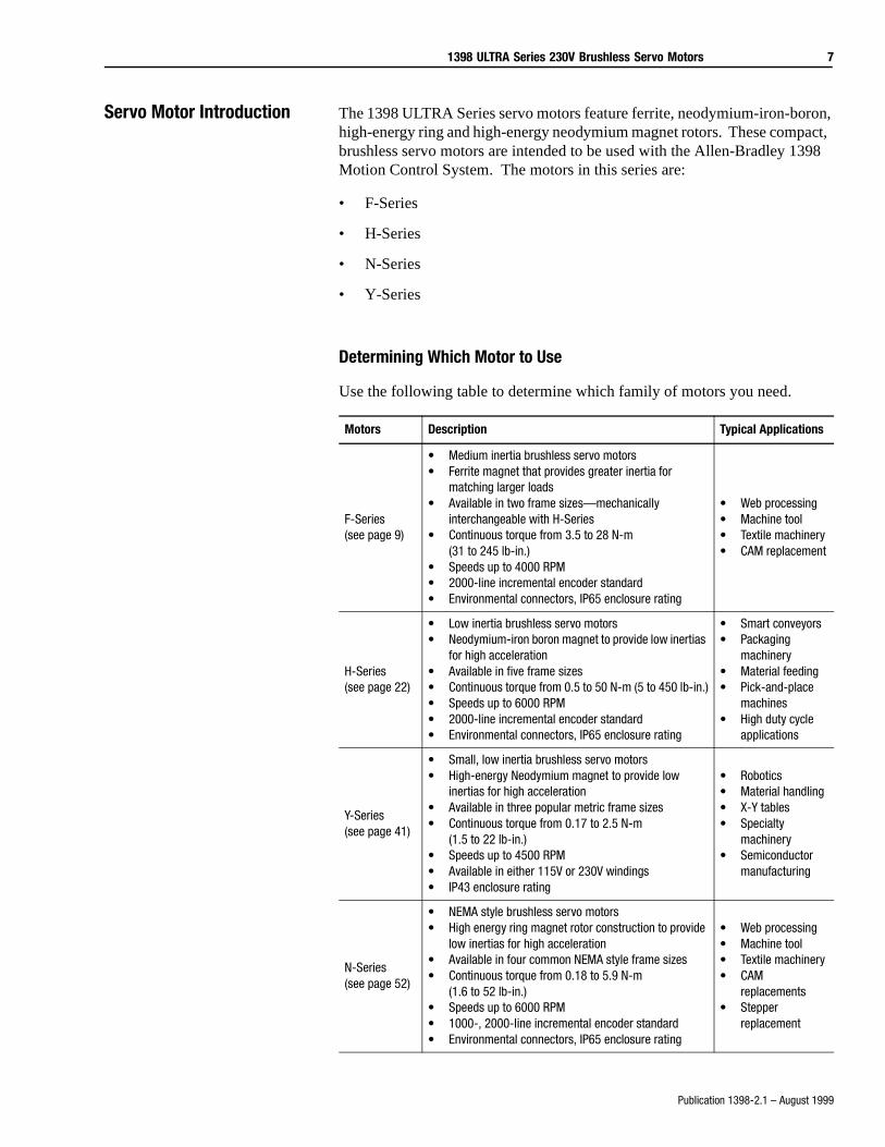
Determining Which Motor to Use
Use the following table to determine which family of motors you need.
Motors Description Typical Applications
F-Series(see page 9)
• Medium inertia brushless servo motors• Ferrite magnet that provides greater inertia for
matching larger loads• Available in two frame sizes—mechanically
interchangeable with H-Series• Continuous torque from 3.5 to 28 N-m
(31 to 245 lb-in.)• Speeds up to 4000 RPM• 2000-line incremental encoder standard• Environmental connectors, IP65 enclosure rating
• Web processing• Machine tool• Textile machinery• CAM replacement
H-Series(see page 22)
• Low inertia brushless servo motors• Neodymium-iron boron magnet to provide low inertias
for high acceleration• Available in five frame sizes• Continuous torque from 0.5 to 50 N-m (5 to 450 lb-in.)• Speeds up to 6000 RPM• 2000-line incremental encoder standard• Environmental connectors, IP65 enclosure rating
• Smart conveyors• Packaging
machinery• Material feeding• Pick-and-place
machines• High duty cycle
applications
Y-Series(see page 41)
• Small, low inertia brushless servo motors• High-energy Neodymium magnet to provide low
inertias for high acceleration• Available in three popular metric frame sizes• Continuous torque from 0.17 to 2.5 N-m
(1.5 to 22 lb-in.)• Speeds up to 4500 RPM• Available in either 115V or 230V windings• IP43 enclosure rating
• Robotics• Material handling• X-Y tables• Specialty
machinery• Semiconductor
manufacturing
N-Series(see page 52)
• NEMA style brushless servo motors• High energy ring magnet rotor construction to provide
low inertias for high acceleration• Available in four common NEMA style frame sizes• Continuous torque from 0.18 to 5.9 N-m
(1.6 to 52 lb-in.)• Speeds up to 6000 RPM• 1000-, 2000-line incremental encoder standard• Environmental connectors, IP65 enclosure rating
• Web processing• Machine tool• Textile machinery• CAM
replacements• Stepper
replacement
8 1398 ULTRA Series 230V Brushless Servo Motors
Publication 1398-2.1 – August 1999
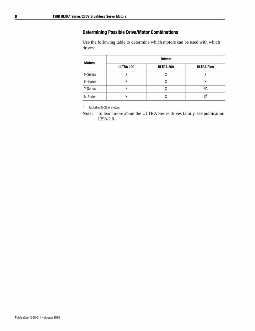
Determining Possible Drive/Motor Combinations
Use the following table to determine which motors can be used with which drives:
1 Excluding N-23xx motors.
Note: To learn more about the ULTRA Series drives family, see publication 1398-2.0.
Motors:Drives:
ULTRA 100 ULTRA 200 ULTRA Plus
F-Series X X X
H-Series X X X
Y-Series X X NA
N-Series X X X1
1398 ULTRA Series 230V Brushless Servo Motors 9
Publication 1398-2.1 – August 1999
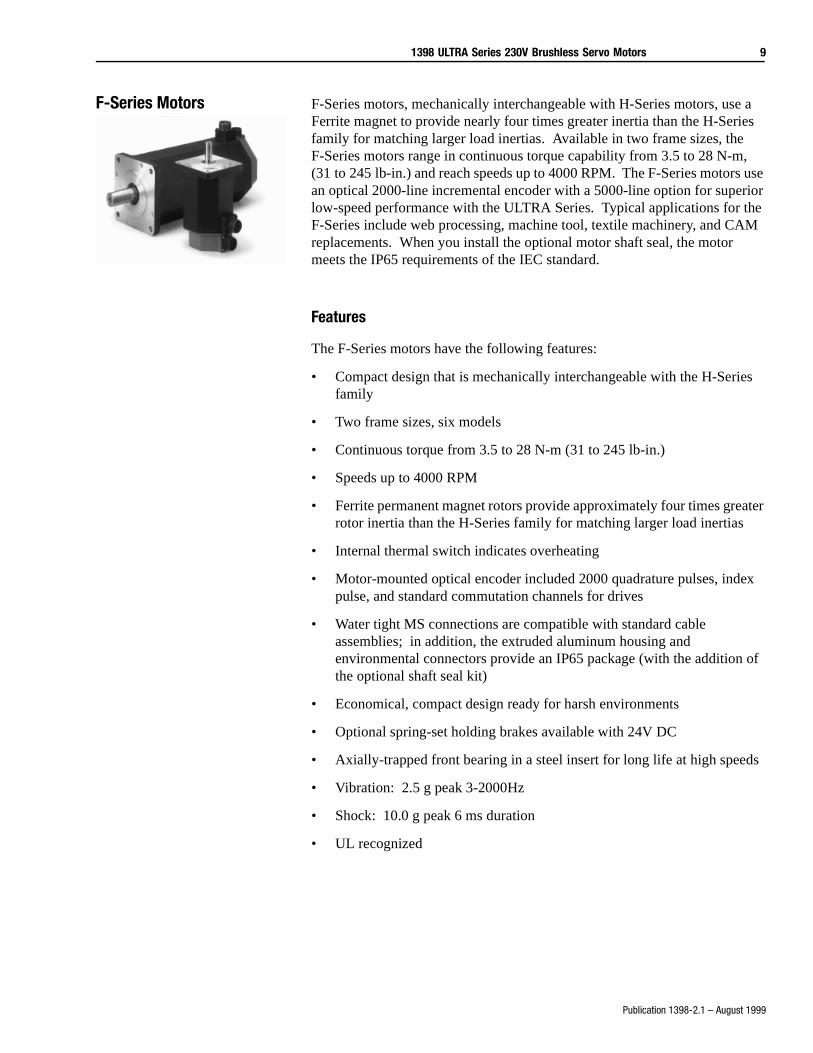
F-Series Motors F-Series motors, mechanically interchangeable with H-Series motors, use a Ferrite magnet to provide nearly four times greater inertia than the H-Series family for matching larger load inertias. Available in two frame sizes, the F-Series motors range in continuous torque capability from 3.5 to 28 N-m, (31 to 245 lb-in.) and reach speeds up to 4000 RPM. The F-Series motors use an optical 2000-line incremental encoder with a 5000-line option for superior low-speed performance with the ULTRA Series. Typical applications for the F-Series include web processing, machine tool, textile machinery, and CAM replacements. When you install the optional motor shaft seal, the motor meets the IP65 requirements of the IEC standard.
Features
The F-Series motors have the following features:
• Compact design that is mechanically interchangeable with the H-Series family
• Two frame sizes, six models
• Continuous torque from 3.5 to 28 N-m (31 to 245 lb-in.)
• Speeds up to 4000 RPM
• Ferrite permanent magnet rotors provide approximately four times greater rotor inertia than the H-Series family for matching larger load inertias
• Internal thermal switch indicates overheating
• Motor-mounted optical encoder included 2000 quadrature pulses, index pulse, and standard commutation channels for drives
• Water tight MS connections are compatible with standard cable assemblies; in addition, the extruded aluminum housing and environmental connectors provide an IP65 package (with the addition of the optional shaft seal kit)
• Economical, compact design ready for harsh environments
• Optional spring-set holding brakes available with 24V DC
• Axially-trapped front bearing in a steel insert for long life at high speeds
• Vibration: 2.5 g peak 3-2000Hz
• Shock: 10.0 g peak 6 ms duration
• UL recognized
10 1398 ULTRA Series 230V Brushless Servo Motors
Publication 1398-2.1 – August 1999
Typical Applications
Typical applications for the F-Series motors are:
• Web and film processing
• Machine tool/metal cutting
• Textile machinery
• CAM replacements
Characteristics
• Higher inertia matching capability
• Heavy duty continuous operations
• Environmentally rugged
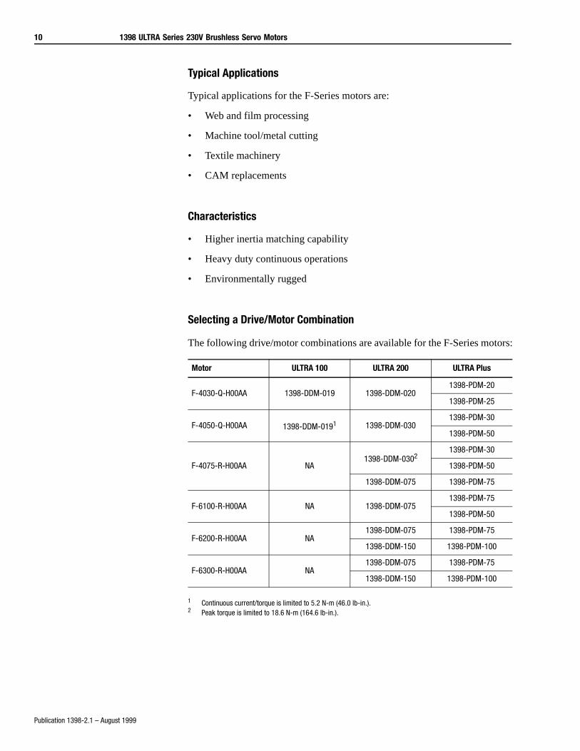
Selecting a Drive/Motor Combination
The following drive/motor combinations are available for the F-Series motors:
1 Continuous current/torque is limited to 5.2 N-m (46.0 lb-in.).2 Peak torque is limited to 18.6 N-m (164.6 lb-in.).
Motor ULTRA 100 ULTRA 200 ULTRA Plus
F-4030-Q-H00AA 1398-DDM-019 1398-DDM-0201398-PDM-20
1398-PDM-25
F-4050-Q-H00AA 1398-DDM-0191 1398-DDM-0301398-PDM-30
1398-PDM-50
F-4075-R-H00AA NA1398-DDM-0302
1398-PDM-30
1398-PDM-50
1398-DDM-075 1398-PDM-75
F-6100-R-H00AA NA 1398-DDM-0751398-PDM-75
1398-PDM-50
F-6200-R-H00AA NA1398-DDM-075 1398-PDM-75
1398-DDM-150 1398-PDM-100
F-6300-R-H00AA NA1398-DDM-075 1398-PDM-75
1398-DDM-150 1398-PDM-100
1398 ULTRA Series 230V Brushless Servo Motors 11
Publication 1398-2.1 – August 1999
F-Series Specifications This section contains the mechanical, thermostat and winding specifications for the F-Series motor family, as well as the load force ratings and performance specifications for every combination of ULTRA series drives and F-Series motors. It also provides motor dimensions, connector pin and signal designations, and all motor and connector ordering information.
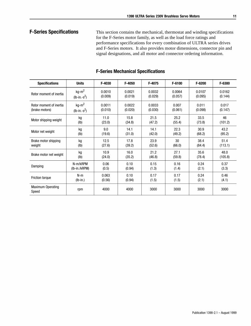
F-Series Mechanical Specifications
Specifications Units F-4030 F-4050 F-4075 F-6100 F-6200 F-6300
Rotor moment of inertiakg-m2
(lb-in.-s2)
0.0010(0.009)
0.0021(0.019)
0.0032(0.029)
0.0064(0.057)
0.0107(0.095)
0.0162(0.144)
Rotor moment of inertia (brake motors)
kg-m2
(lb-in.-s2)
0.0011(0.010)
0.0022(0.020)
0.0033(0.030)
0.007(0.061)
0.011(0.098)
0.017(0.147)
Motor shipping weightkg(lb)
11.0(23.0)
15.8(34.8)
21.5(47.2)
25.2(55.4)
33.5(73.8)
46(101.2)
Motor net weightkg(lb)
9.0(19.6)
14.1(31.0)
14.1(42.0)
22.3(49.2)
30.9(68.2)
43.2(95.2)
Brake motor shipping weight
kg(lb)
12.5(27.6)
17.8(39.2)
23.9(52.6)
30(66.0)
38.4(84.4)
51.4(113.1)
Brake motor net weightkg(lb)
10.9(24.0)
16.0(35.2)
21.2(46.8)
27.1(59.8)
35.6(78.4)
48.0(105.8)
DampingN-m/kRPM
(lb-in./kRPM)0.06(0.5)
0.10(0.94)
0.15(1.3)
0.16(1.4)
0.24(2.1)
0.37(3.3)
Friction torqueN-m
(lb-in.)0.063(0.56)
0.10(0.94)
0.17(1.5)
0.17(1.5)
0.24(2.1)
0.46(4.1)
Maximum Operating Speed
rpm 4000 4000 3000 3000 3000 3000
12 1398 ULTRA Series 230V Brushless Servo Motors
Publication 1398-2.1 – August 1999
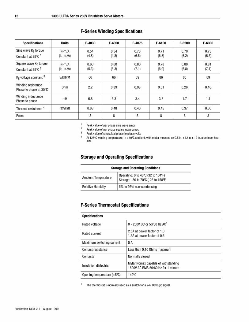
F-Series Winding Specifications
1 Peak value of per phase sine wave amps.2 Peak value of per phase square wave amps3 Peak value of sinusoidal phase to phase volts4 At 125ºC winding temperature, in a 40ºC ambient, with motor mounted on 0.5 in. x 12 in. x 12 in. aluminum heat
sink.
Storage and Operating Specifications
F-Series Thermostat Specifications
1 The thermostat is normally used as a switch for a 24V DC logic signal.
Specifications Units F-4030 F-4050 F-4075 F-6100 F-6200 F-6300
Sine wave KT torque
Constant at 25ºC 1N-m/A
(lb-in./A)0.54(4.8)
0.54(4.8)
0.73(6.5)
0.71(6.3)
0.70(6.2)
0.73(6.5)
Square wave KT torque
Constant at 25ºC 2N-m/A
(lb-in./A)0.60(5.3)
0.60(5.3)
0.80(7.1)
0.78(6.9)
0.80(6.8)
0.81(7.1)
KE voltage constant 3 V/kRPM 66 66 89 86 85 89
Winding resistance Phase to phase at 25ºC
Ohm 2.2 0.89 0.98 0.51 0.26 0.16
Winding inductance Phase to phase
mH 6.8 3.3 3.4 3.3 1.7 1.1
Thermal resistance 4 ºC/Watt 0.63 0.48 0.40 0.45 0.37 0.30
Poles 8 8 8 8 8 8
Storage and Operating Conditions
Ambient TemperatureOperating: 0 to 40ºC (32 to 104ºF)Storage: -30 to 70ºC (-25 to 158ºF)
Relative Humidity 5% to 95% non-condensing
Specifications
Rated voltage 0 - 250V DC or 50/60 Hz AC1
Rated current2.5A at power factor of 1.01.6A at power factor of 0.6
Maximum switching current 5 A
Contact resistance Less than 0.10 Ohms maximum
Contacts Normally closed
Insulation dielectricMylar Nomex capable of withstanding 1500V AC RMS 50/60 Hz for 1 minute
Opening temperature (±5ºC) 140ºC
1398 ULTRA Series 230V Brushless Servo Motors 13
Publication 1398-2.1 – August 1999
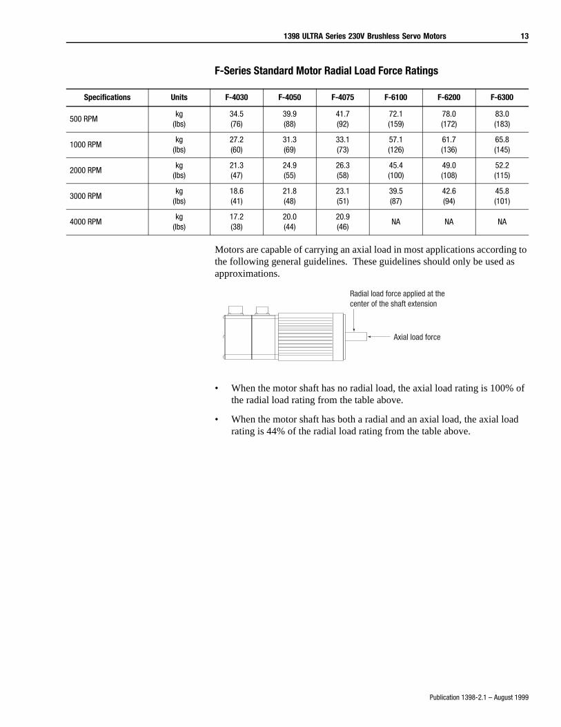
F-Series Standard Motor Radial Load Force Ratings
Motors are capable of carrying an axial load in most applications according to the following general guidelines. These guidelines should only be used as approximations.
• When the motor shaft has no radial load, the axial load rating is 100% of the radial load rating from the table above.
• When the motor shaft has both a radial and an axial load, the axial load rating is 44% of the radial load rating from the table above.
Specifications Units F-4030 F-4050 F-4075 F-6100 F-6200 F-6300
500 RPMkg
(lbs)34.5(76)
39.9(88)
41.7(92)
72.1(159)
78.0(172)
83.0(183)
1000 RPMkg
(lbs)27.2(60)
31.3(69)
33.1(73)
57.1(126)
61.7(136)
65.8(145)
2000 RPMkg
(lbs)21.3(47)
24.9(55)
26.3(58)
45.4(100)
49.0(108)
52.2(115)
3000 RPMkg
(lbs)18.6(41)
21.8(48)
23.1(51)
39.5(87)
42.6(94)
45.8(101)
4000 RPMkg
(lbs)17.2(38)
20.0(44)
20.9(46)
NA NA NA
Radial load force applied at the center of the shaft extension
Axial load force
14 1398 ULTRA Series 230V Brushless Servo Motors
Publication 1398-2.1 – August 1999
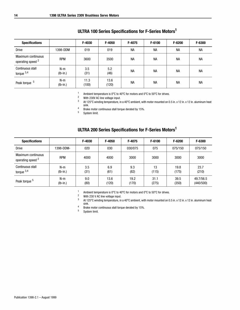
ULTRA 100 Series Specifications for F-Series Motors1
1 Ambient temperature is 0ºC to 40ºC for motors and 0ºC to 50ºC for drives.2 With 230V AC line voltage input.3 At 125ºC winding temperature, in a 40ºC ambient, with motor mounted on 0.5 in. x 12 in. x 12 in. aluminum heat
sink.4 Brake motor continuous stall torque derated by 15%.5 System limit.
ULTRA 200 Series Specifications for F-Series Motors1
1 Ambient temperature is 0ºC to 40ºC for motors and 0ºC to 50ºC for drives.2 With 230 V AC line voltage input.3 At 125ºC winding temperature, in a 40ºC ambient, with motor mounted on 0.5 in. x 12 in. x 12 in. aluminum heat
sink.4 Brake motor continuous stall torque derated by 15%.5 System limit.
Specifications F-4030 F-4050 F-4075 F-6100 F-6200 F-6300
Drive 1398-DDM 019 019 NA NA NA NA
Maximum continuous
operating speed 2RPM 3600 3500 NA NA NA NA
Continuous stall
torque 3,4N-m
(lb-in.)3.5(31)
5.2(46)
NA NA NA NA
Peak torque 5N-m
(lb-in.)11.3(100)
13.6(120)
NA NA NA NA
Specifications F-4030 F-4050 F-4075 F-6100 F-6200 F-6300
Drive 1398-DDM- 020 030 030/075 075 075/150 075/150
Maximum continuous
operating speed 2RPM 4000 4000 3000 3000 3000 3000
Continuous stall
torque 3,4N-m
(lb-in.)3.5(31)
6.9(61)
9.3(82)
13(115)
19.8(175)
23.7(210)
Peak torque 5N-m
(lb-in.)9.0(80)
13.6(120)
19.2(170)
31.1(275)
39.5(350)
49.7/56.5(440/500)
1398 ULTRA Series 230V Brushless Servo Motors 15
Publication 1398-2.1 – August 1999
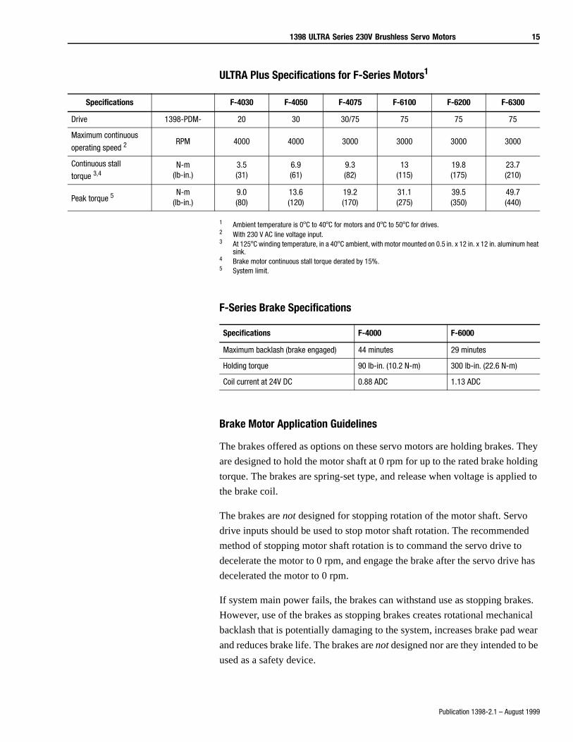
ULTRA Plus Specifications for F-Series Motors1
1 Ambient temperature is 0ºC to 40ºC for motors and 0ºC to 50ºC for drives.2 With 230 V AC line voltage input.3 At 125ºC winding temperature, in a 40ºC ambient, with motor mounted on 0.5 in. x 12 in. x 12 in. aluminum heat
sink.4 Brake motor continuous stall torque derated by 15%.5 System limit.
F-Series Brake Specifications
Brake Motor Application Guidelines
The brakes offered as options on these servo motors are holding brakes. They
are designed to hold the motor shaft at 0 rpm for up to the rated brake holding
torque. The brakes are spring-set type, and release when voltage is applied to
the brake coil.
The brakes are not designed for stopping rotation of the motor shaft. Servo
drive inputs should be used to stop motor shaft rotation. The recommended
method of stopping motor shaft rotation is to command the servo drive to
decelerate the motor to 0 rpm, and engage the brake after the servo drive has
decelerated the motor to 0 rpm.
If system main power fails, the brakes can withstand use as stopping brakes.
However, use of the brakes as stopping brakes creates rotational mechanical
backlash that is potentially damaging to the system, increases brake pad wear
and reduces brake life. The brakes are not designed nor are they intended to be
used as a safety device.
Specifications F-4030 F-4050 F-4075 F-6100 F-6200 F-6300
Drive 1398-PDM- 20 30 30/75 75 75 75
Maximum continuous
operating speed 2RPM 4000 4000 3000 3000 3000 3000
Continuous stall
torque 3,4N-m
(lb-in.)3.5(31)
6.9(61)
9.3(82)
13(115)
19.8(175)
23.7(210)
Peak torque 5N-m
(lb-in.)9.0(80)
13.6(120)
19.2(170)
31.1(275)
39.5(350)
49.7(440)
Specifications F-4000 F-6000
Maximum backlash (brake engaged) 44 minutes 29 minutes
Holding torque 90 lb-in. (10.2 N-m) 300 lb-in. (22.6 N-m)
Coil current at 24V DC 0.88 ADC 1.13 ADC
16 1398 ULTRA Series 230V Brushless Servo Motors
Publication 1398-2.1 – August 1999
A separate power source is required to disengage the brake. This power
source may be controlled by the servo motor controls, in addition to manual
operator controls.
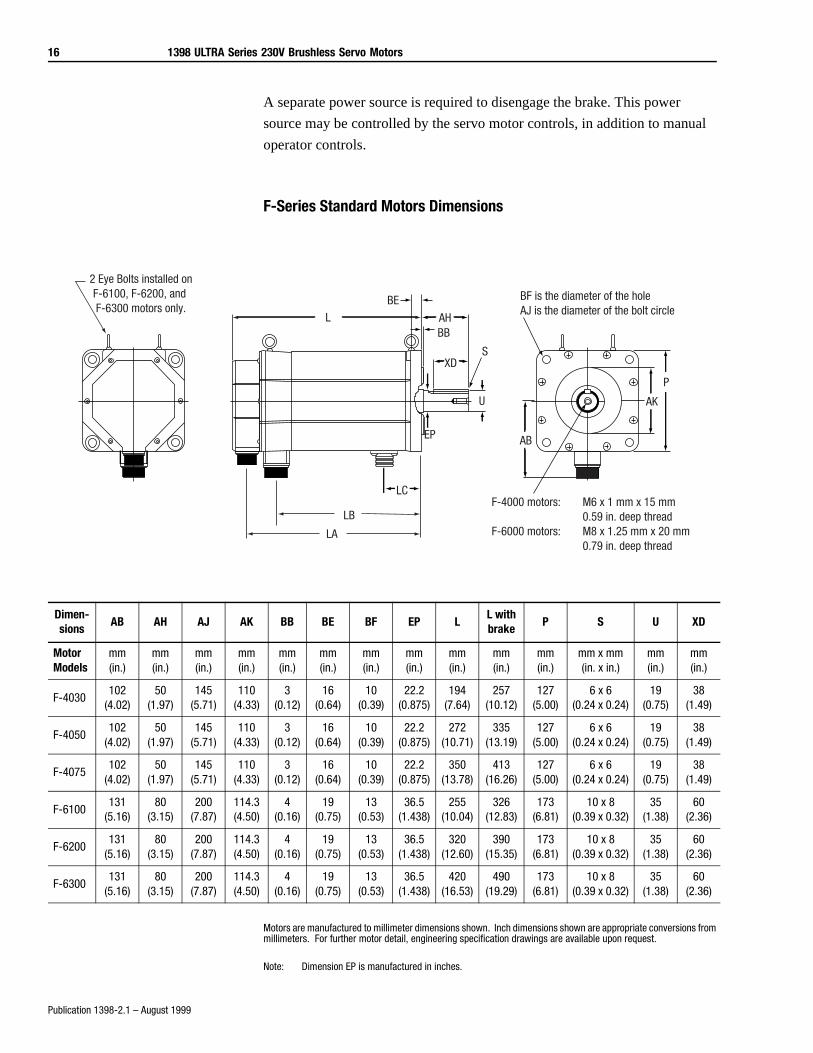
F-Series Standard Motors Dimensions
Motors are manufactured to millimeter dimensions shown. Inch dimensions shown are appropriate conversions from millimeters. For further motor detail, engineering specification drawings are available upon request.
Note: Dimension EP is manufactured in inches.
2 Eye Bolts installed onF-6100, F-6200, and F-6300 motors only.
AHBB
EP
L
S
U
XD
BF is the diameter of the holeAJ is the diameter of the bolt circle
F-4000 motors: M6 x 1 mm x 15 mm0.59 in. deep thread
F-6000 motors: M8 x 1.25 mm x 20 mm0.79 in. deep thread
AB
AK
P
BE
LC
LB
LA
Dimen-sions
AB AH AJ AK BB BE BF EP LL with brake
P S U XD
Motor Models
mm(in.)
mm(in.)
mm(in.)
mm(in.)
mm(in.)
mm(in.)
mm(in.)
mm(in.)
mm(in.)
mm(in.)
mm(in.)
mm x mm(in. x in.)
mm(in.)
mm(in.)
F-4030102
(4.02)50
(1.97)145
(5.71)110
(4.33)3
(0.12)16
(0.64)10
(0.39)22.2
(0.875)194
(7.64)257
(10.12)127
(5.00)6 x 6
(0.24 x 0.24)19
(0.75)38
(1.49)
F-4050102
(4.02)50
(1.97)145
(5.71)110
(4.33)3
(0.12)16
(0.64)10
(0.39)22.2
(0.875)272
(10.71)335
(13.19)127
(5.00)6 x 6
(0.24 x 0.24)19
(0.75)38
(1.49)
F-4075102
(4.02)50
(1.97)145
(5.71)110
(4.33)3
(0.12)16
(0.64)10
(0.39)22.2
(0.875)350
(13.78)413
(16.26)127
(5.00)6 x 6
(0.24 x 0.24)19
(0.75)38
(1.49)
F-6100131
(5.16)80
(3.15)200
(7.87)114.3(4.50)
4(0.16)
19(0.75)
13(0.53)
36.5(1.438)
255(10.04)
326(12.83)
173(6.81)
10 x 8(0.39 x 0.32)
35(1.38)
60(2.36)
F-6200131
(5.16)80
(3.15)200
(7.87)114.3(4.50)
4(0.16)
19(0.75)
13(0.53)
36.5(1.438)
320(12.60)
390(15.35)
173(6.81)
10 x 8(0.39 x 0.32)
35(1.38)
60(2.36)
F-6300131
(5.16)80
(3.15)200
(7.87)114.3(4.50)
4(0.16)
19(0.75)
13(0.53)
36.5(1.438)
420(16.53)
490(19.29)
173(6.81)
10 x 8(0.39 x 0.32)
35(1.38)
60(2.36)
1398 ULTRA Series 230V Brushless Servo Motors 17
Publication 1398-2.1 – August 1999
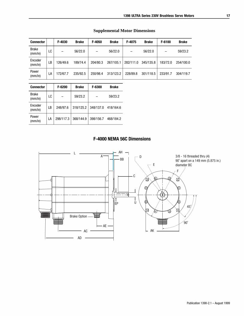
Supplemental Motor Dimensions
F-4000 NEMA 56C Dimensions
Connector F-4030 Brake F-4050 Brake F-4075 Brake F-6100 Brake
Brake(mm/in)
LC – 56/22.0 – 56/22.0 – 56/22.0 – 59/23.2
Encoder(mm/in)
LB 126/49.6 189/74.4 204/80.3 267/105.1 282/111.0 345/135.8 183/72.0 254/100.0
Power(mm/in)
LA 172/67.7 235/92.5 250/98.4 313/123.2 228/89.8 301/118.5 233/91.7 304/119.7
Connector F-6200 Brake F-6300 Brake
Brake(mm/in)
LC – 59/23.2 – 59/23.2
Encoder(mm/in)
LB 248/97.6 318/125.2 348/137.0 418/164.6
Power(mm/in)
LA 298/117.3 368/144.9 398/156.7 468/184.2
Brake Option
L AH
BB
U
AK
A
C
D
E
F
EP45˚
90˚
3/8 - 16 threaded thru (4) 90˚ apart on a 149 mm (5.875 in.) diameter BC
AD
AC
AE
18 1398 ULTRA Series 230V Brushless Servo Motors
Publication 1398-2.1 – August 1999
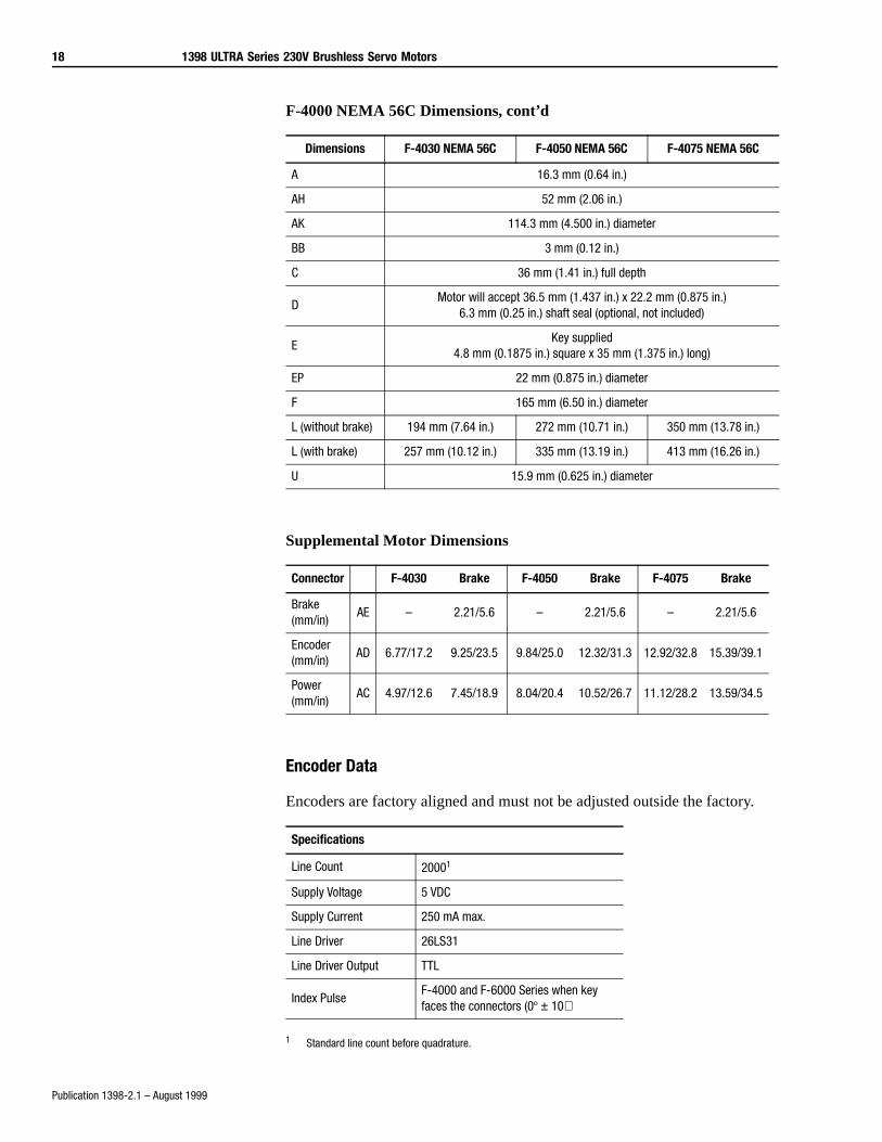
F-4000 NEMA 56C Dimensions, cont’d
Supplemental Motor Dimensions
Encoder Data
Encoders are factory aligned and must not be adjusted outside the factory.
1 Standard line count before quadrature.
Dimensions F-4030 NEMA 56C F-4050 NEMA 56C F-4075 NEMA 56C
A 16.3 mm (0.64 in.)
AH 52 mm (2.06 in.)
AK 114.3 mm (4.500 in.) diameter
BB 3 mm (0.12 in.)
C 36 mm (1.41 in.) full depth
DMotor will accept 36.5 mm (1.437 in.) x 22.2 mm (0.875 in.)
6.3 mm (0.25 in.) shaft seal (optional, not included)
EKey supplied
4.8 mm (0.1875 in.) square x 35 mm (1.375 in.) long)
EP 22 mm (0.875 in.) diameter
F 165 mm (6.50 in.) diameter
L (without brake) 194 mm (7.64 in.) 272 mm (10.71 in.) 350 mm (13.78 in.)
L (with brake) 257 mm (10.12 in.) 335 mm (13.19 in.) 413 mm (16.26 in.)
U 15.9 mm (0.625 in.) diameter
Connector F-4030 Brake F-4050 Brake F-4075 Brake
Brake(mm/in)
AE – 2.21/5.6 – 2.21/5.6 – 2.21/5.6
Encoder(mm/in)
AD 6.77/17.2 9.25/23.5 9.84/25.0 12.32/31.3 12.92/32.8 15.39/39.1
Power(mm/in)
AC 4.97/12.6 7.45/18.9 8.04/20.4 10.52/26.7 11.12/28.2 13.59/34.5
Specifications
Line Count 20001
Supply Voltage 5 VDC
Supply Current 250 mA max.
Line Driver 26LS31
Line Driver Output TTL
Index PulseF-4000 and F-6000 Series when key faces the connectors (0º ± 10)
1398 ULTRA Series 230V Brushless Servo Motors 19
Publication 1398-2.1 – August 1999
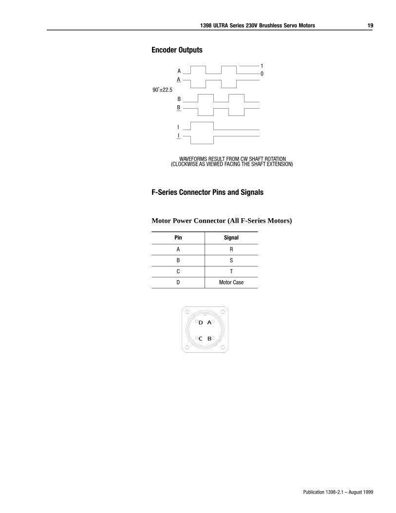
Encoder Outputs
F-Series Connector Pins and Signals
Motor Power Connector (All F-Series Motors)
Pin Signal
A R
B S
C T
D Motor Case
10A
B
I
I
B
A
90˚±22.5
WAVEFORMS RESULT FROM CW SHAFT ROTATION(CLOCKWISE AS VIEWED FACING THE SHAFT EXTENSION)
P002
A
BC
D
20 1398 ULTRA Series 230V Brushless Servo Motors
Publication 1398-2.1 – August 1999
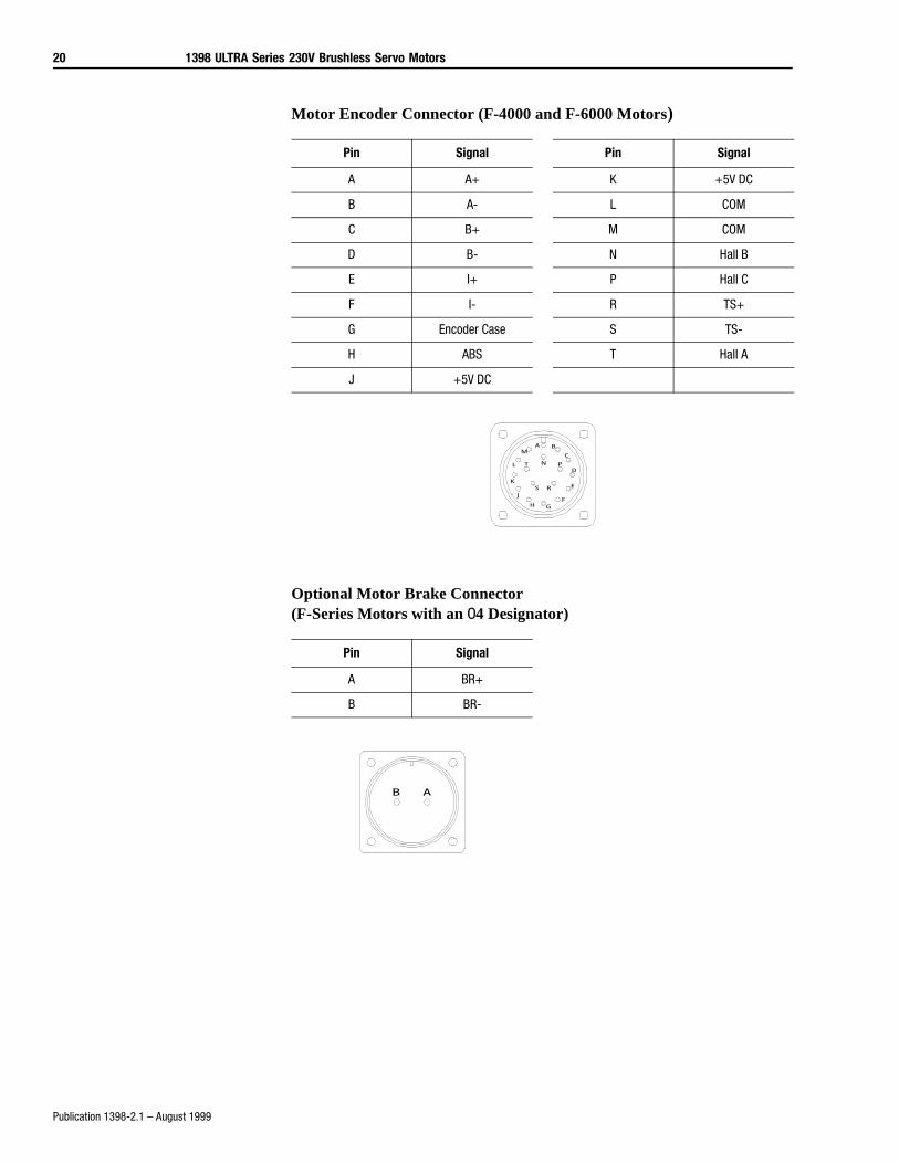
Motor Encoder Connector (F-4000 and F-6000 Motors)
Optional Motor Brake Connector (F-Series Motors with an 04 Designator)
Pin Signal Pin Signal
A A+ K +5V DC
B A- L COM
C B+ M COM
D B- N Hall B
E I+ P Hall C
F I- R TS+
G Encoder Case S TS-
H ABS T Hall A
J +5V DC
Pin Signal
A BR+
B BR-
A B
C
D
E
FGH
J
K
L
M
N P
RS
T
P000
B A
P0003
1398 ULTRA Series 230V Brushless Servo Motors 21
Publication 1398-2.1 – August 1999
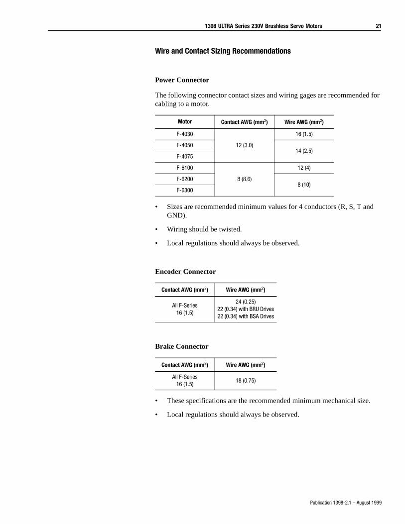
Wire and Contact Sizing Recommendations
Power Connector
The following connector contact sizes and wiring gages are recommended for cabling to a motor.
• Sizes are recommended minimum values for 4 conductors (R, S, T and GND).
• Wiring should be twisted.
• Local regulations should always be observed.
Encoder Connector
Brake Connector
• These specifications are the recommended minimum mechanical size.
• Local regulations should always be observed.
Motor Contact AWG (mm2) Wire AWG (mm2)
F-4030
12 (3.0)
16 (1.5)
F-405014 (2.5)
F-4075
F-6100
8 (8.6)
12 (4)
F-62008 (10)
F-6300
Contact AWG (mm2) Wire AWG (mm2)
All F-Series16 (1.5)
24 (0.25)22 (0.34) with BRU Drives22 (0.34) with BSA Drives
Contact AWG (mm2) Wire AWG (mm2)
All F-Series16 (1.5)
18 (0.75)
22 1398 ULTRA Series 230V Brushless Servo Motors
Publication 1398-2.1 – August 1999
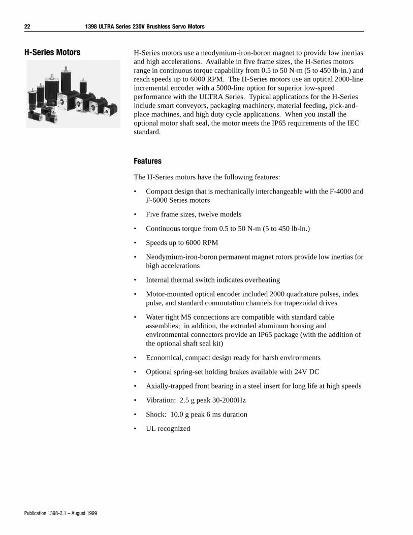
H-Series Motors H-Series motors use a neodymium-iron-boron magnet to provide low inertias and high accelerations. Available in five frame sizes, the H-Series motors range in continuous torque capability from 0.5 to 50 N-m (5 to 450 lb-in.) and reach speeds up to 6000 RPM. The H-Series motors use an optical 2000-line incremental encoder with a 5000-line option for superior low-speed performance with the ULTRA Series. Typical applications for the H-Series include smart conveyors, packaging machinery, material feeding, pick-and-place machines, and high duty cycle applications. When you install the optional motor shaft seal, the motor meets the IP65 requirements of the IEC standard.
Features
The H-Series motors have the following features:
• Compact design that is mechanically interchangeable with the F-4000 and F-6000 Series motors
• Five frame sizes, twelve models
• Continuous torque from 0.5 to 50 N-m (5 to 450 lb-in.)
• Speeds up to 6000 RPM
• Neodymium-iron-boron permanent magnet rotors provide low inertias for high accelerations
• Internal thermal switch indicates overheating
• Motor-mounted optical encoder included 2000 quadrature pulses, index pulse, and standard commutation channels for trapezoidal drives
• Water tight MS connections are compatible with standard cable assemblies; in addition, the extruded aluminum housing and environmental connectors provide an IP65 package (with the addition of the optional shaft seal kit)
• Economical, compact design ready for harsh environments
• Optional spring-set holding brakes available with 24V DC
• Axially-trapped front bearing in a steel insert for long life at high speeds
• Vibration: 2.5 g peak 30-2000Hz
• Shock: 10.0 g peak 6 ms duration
• UL recognized
1398 ULTRA Series 230V Brushless Servo Motors 23
Publication 1398-2.1 – August 1999
Typical Applications
Typical applications for the H-Series motors are:
• Smart conveyors
• Packaging machinery
• Punch press/material feeding
• Robotic pick-and-place
• High duty cycle applications
Characteristics
• High acceleration and peak torques
• High-speed point-to-point positioning
• Environmentally rugged
24 1398 ULTRA Series 230V Brushless Servo Motors
Publication 1398-2.1 – August 1999
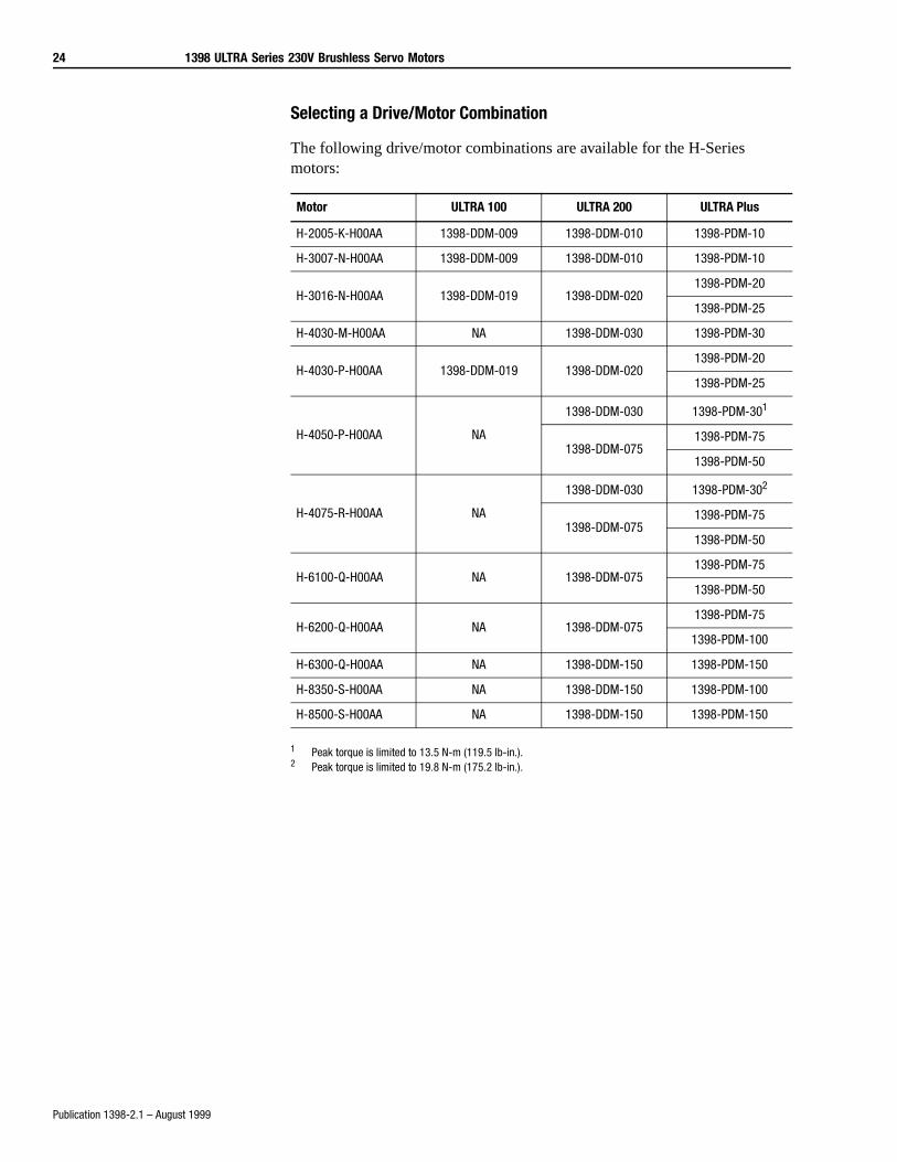
Selecting a Drive/Motor Combination
The following drive/motor combinations are available for the H-Series motors:
1 Peak torque is limited to 13.5 N-m (119.5 lb-in.).2 Peak torque is limited to 19.8 N-m (175.2 lb-in.).
Motor ULTRA 100 ULTRA 200 ULTRA Plus
H-2005-K-H00AA 1398-DDM-009 1398-DDM-010 1398-PDM-10
H-3007-N-H00AA 1398-DDM-009 1398-DDM-010 1398-PDM-10
H-3016-N-H00AA 1398-DDM-019 1398-DDM-0201398-PDM-20
1398-PDM-25
H-4030-M-H00AA NA 1398-DDM-030 1398-PDM-30
H-4030-P-H00AA 1398-DDM-019 1398-DDM-0201398-PDM-20
1398-PDM-25
H-4050-P-H00AA NA
1398-DDM-030 1398-PDM-301
1398-DDM-0751398-PDM-75
1398-PDM-50
H-4075-R-H00AA NA
1398-DDM-030 1398-PDM-302
1398-DDM-0751398-PDM-75
1398-PDM-50
H-6100-Q-H00AA NA 1398-DDM-0751398-PDM-75
1398-PDM-50
H-6200-Q-H00AA NA 1398-DDM-0751398-PDM-75
1398-PDM-100
H-6300-Q-H00AA NA 1398-DDM-150 1398-PDM-150
H-8350-S-H00AA NA 1398-DDM-150 1398-PDM-100
H-8500-S-H00AA NA 1398-DDM-150 1398-PDM-150
1398 ULTRA Series 230V Brushless Servo Motors 25
Publication 1398-2.1 – August 1999
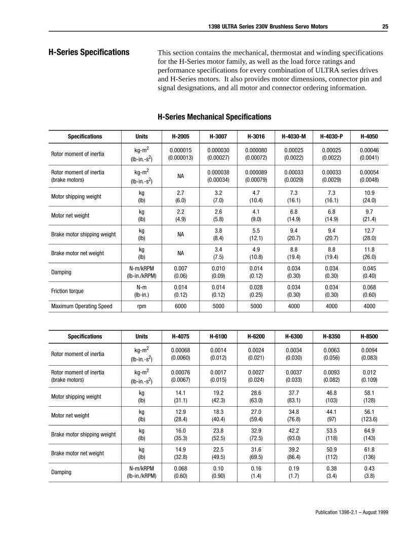
H-Series Specifications This section contains the mechanical, thermostat and winding specifications for the H-Series motor family, as well as the load force ratings and performance specifications for every combination of ULTRA series drives and H-Series motors. It also provides motor dimensions, connector pin and signal designations, and all motor and connector ordering information.
H-Series Mechanical Specifications
Specifications Units H-2005 H-3007 H-3016 H-4030-M H-4030-P H-4050
Rotor moment of inertiakg-m2
(lb-in.-s2)
0.000015(0.000013)
0.000030(0.00027)
0.000080(0.00072)
0.00025(0.0022)
0.00025(0.0022)
0.00046(0.0041)
Rotor moment of inertia (brake motors)
kg-m2
(lb-in.-s2)NA
0.000038(0.00034)
0.000089(0.00079)
0.00033(0.0029)
0.00033(0.0029)
0.00054(0.0048)
Motor shipping weightkg(lb)
2.7(6.0)
3.2(7.0)
4.7(10.4)
7.3(16.1)
7.3(16.1)
10.9(24.0)
Motor net weightkg(lb)
2.2(4.9)
2.6(5.8)
4.1(9.0)
6.8(14.9)
6.8(14.9)
9.7(21.4)
Brake motor shipping weightkg(lb)
NA3.8
(8.4)5.5
(12.1)9.4
(20.7)9.4
(20.7)12.7(28.0)
Brake motor net weightkg(lb)
NA3.4
(7.5)4.9
(10.8)8.8
(19.4)8.8
(19.4)11.8(26.0)
DampingN-m/kRPM
(lb-in./kRPM)0.007(0.06)
0.010(0.09)
0.014(0.12)
0.034(0.30)
0.034(0.30)
0.045(0.40)
Friction torqueN-m
(lb-in.)0.014(0.12)
0.014(0.12)
0.028(0.25)
0.034(0.30)
0.034(0.30)
0.068(0.60)
Maximum Operating Speed rpm 6000 5000 5000 4000 4000 4000
Specifications Units H-4075 H-6100 H-6200 H-6300 H-8350 H-8500
Rotor moment of inertiakg-m2
(lb-in.-s2)
0.00068(0.0060)
0.0014(0.012)
0.0024(0.021)
0.0034(0.030)
0.0063(0.056)
0.0094(0.083)
Rotor moment of inertia (brake motors)
kg-m2
(lb-in.-s2)
0.00076(0.0067)
0.0017(0.015)
0.0027(0.024)
0.0037(0.033)
0.0093(0.082)
0.012(0.109)
Motor shipping weightkg(lb)
14.1(31.1)
19.2(42.3)
28.6(63.0)
37.7(83.1)
46.8(103)
58.1(128)
Motor net weightkg(lb)
12.9(28.4)
18.3(40.4)
27.0(59.4)
34.8(76.8)
44.1(97)
56.1(123.6)
Brake motor shipping weightkg(lb)
16.0(35.3)
23.8(52.5)
32.9(72.5)
42.2(93.0)
53.5(118)
64.9(143)
Brake motor net weightkg(lb)
14.9(32.8)
22.5(49.5)
31.6(69.5)
39.2(86.4)
50.9(112)
61.8(136)
DampingN-m/kRPM
(lb-in./kRPM)0.068(0.60)
0.10(0.90)
0.16(1.4)
0.19(1.7)
0.38(3.4)
0.43(3.8)
26 1398 ULTRA Series 230V Brushless Servo Motors
Publication 1398-2.1 – August 1999
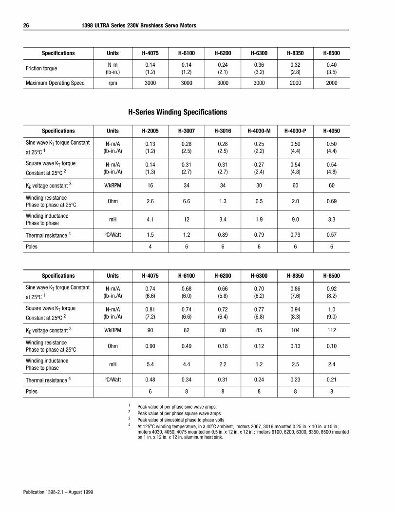
H-Series Winding Specifications
1 Peak value of per phase sine wave amps.2 Peak value of per phase square wave amps3 Peak value of sinusoidal phase to phase volts4 At 125ºC winding temperature, in a 40ºC ambient; motors 3007, 3016 mounted 0.25 in. x 10 in. x 10 in.;
motors 4030, 4050, 4075 mounted on 0.5 in. x 12 in. x 12 in.; motors 6100, 6200, 6300, 8350, 8500 mounted on 1 in. x 12 in. x 12 in. aluminum heat sink.
Friction torqueN-m
(lb-in.)0.14(1.2)
0.14(1.2)
0.24(2.1)
0.36(3.2)
0.32(2.8)
0.40(3.5)
Maximum Operating Speed rpm 3000 3000 3000 3000 2000 2000
Specifications Units H-4075 H-6100 H-6200 H-6300 H-8350 H-8500
Specifications Units H-2005 H-3007 H-3016 H-4030-M H-4030-P H-4050
Sine wave KT torque Constant
at 25ºC 1N-m/A
(lb-in./A)0.13(1.2)
0.28(2.5)
0.28(2.5)
0.25(2.2)
0.50(4.4)
0.50(4.4)
Square wave KT torque
Constant at 25ºC 2N-m/A
(lb-in./A)0.14(1.3)
0.31(2.7)
0.31(2.7)
0.27(2.4)
0.54(4.8)
0.54(4.8)
KE voltage constant 3 V/kRPM 16 34 34 30 60 60
Winding resistance Phase to phase at 25ºC
Ohm 2.6 6.6 1.3 0.5 2.0 0.69
Winding inductance Phase to phase
mH 4.1 12 3.4 1.9 9.0 3.3
Thermal resistance 4 ºC/Watt 1.5 1.2 0.89 0.79 0.79 0.57
Poles 4 6 6 6 6 6
Specifications Units H-4075 H-6100 H-6200 H-6300 H-8350 H-8500
Sine wave KT torque Constant
at 25ºC 1N-m/A
(lb-in./A)0.74(6.6)
0.68(6.0)
0.66(5.8)
0.70(6.2)
0.86(7.6)
0.92(8.2)
Square wave KT torque
Constant at 25ºC 2N-m/A
(lb-in./A)0.81(7.2)
0.74(6.6)
0.72(6.4)
0.77(6.8)
0.94(8.3)
1.0(9.0)
KE voltage constant 3 V/kRPM 90 82 80 85 104 112
Winding resistance Phase to phase at 25ºC
Ohm 0.90 0.49 0.18 0.12 0.13 0.10
Winding inductance Phase to phase
mH 5.4 4.4 2.2 1.2 2.5 2.4
Thermal resistance 4 ºC/Watt 0.48 0.34 0.31 0.24 0.23 0.21
Poles 6 8 8 8 8 8
1398 ULTRA Series 230V Brushless Servo Motors 27
Publication 1398-2.1 – August 1999
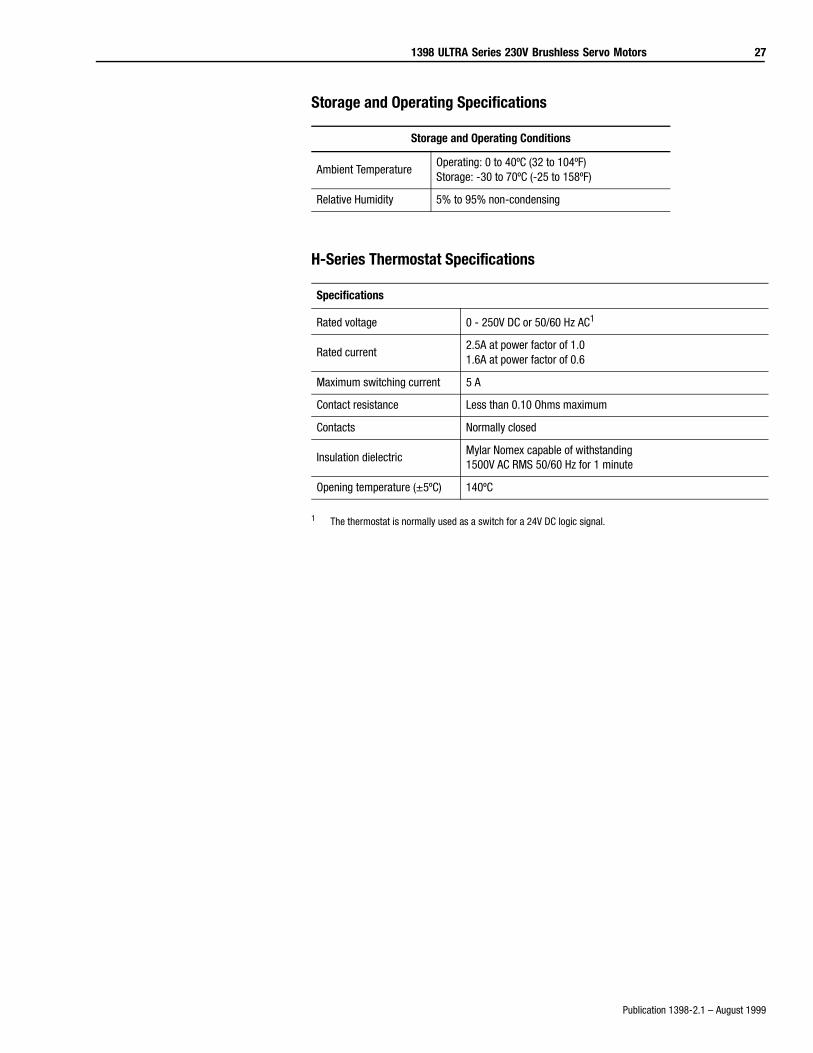
Storage and Operating Specifications
H-Series Thermostat Specifications
1 The thermostat is normally used as a switch for a 24V DC logic signal.
Storage and Operating Conditions
Ambient TemperatureOperating: 0 to 40ºC (32 to 104ºF)Storage: -30 to 70ºC (-25 to 158ºF)
Relative Humidity 5% to 95% non-condensing
Specifications
Rated voltage 0 - 250V DC or 50/60 Hz AC1
Rated current2.5A at power factor of 1.01.6A at power factor of 0.6
Maximum switching current 5 A
Contact resistance Less than 0.10 Ohms maximum
Contacts Normally closed
Insulation dielectricMylar Nomex capable of withstanding 1500V AC RMS 50/60 Hz for 1 minute
Opening temperature (±5ºC) 140ºC
28 1398 ULTRA Series 230V Brushless Servo Motors
Publication 1398-2.1 – August 1999
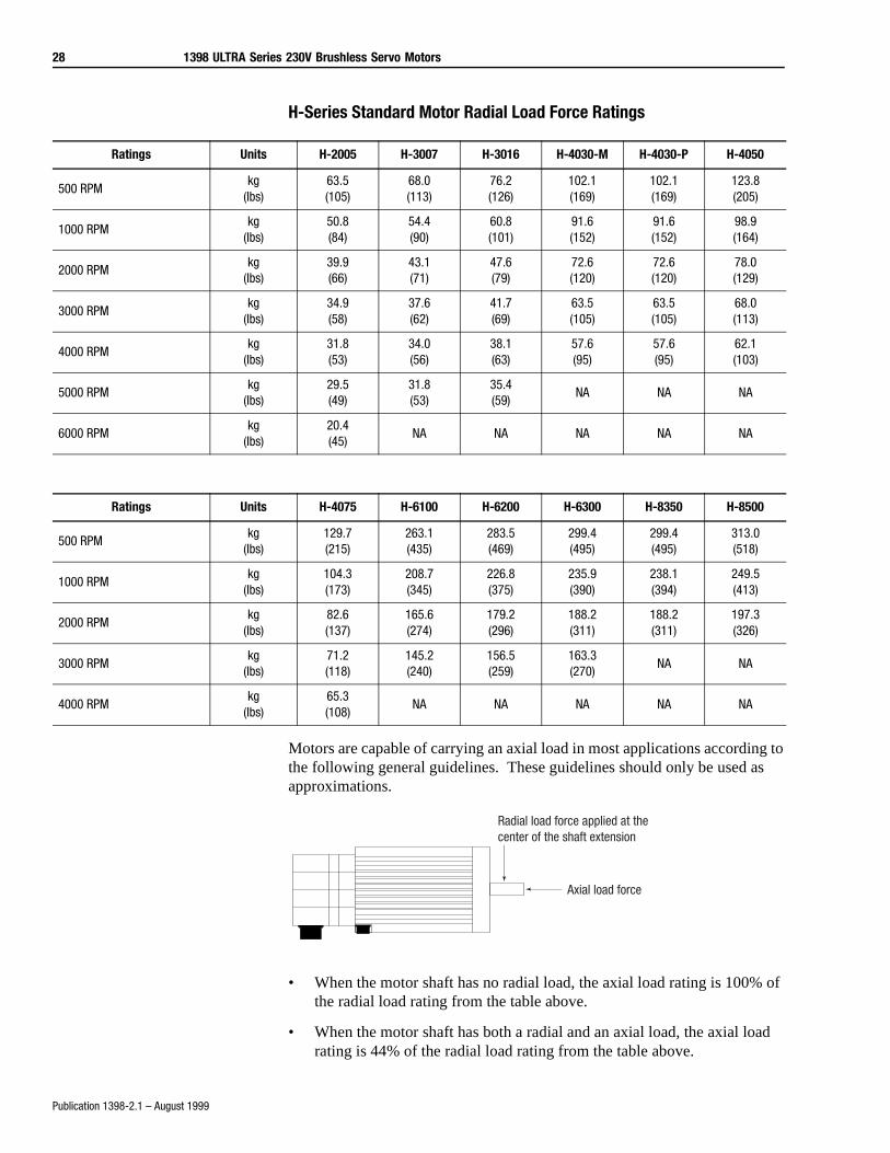
H-Series Standard Motor Radial Load Force Ratings
Motors are capable of carrying an axial load in most applications according to the following general guidelines. These guidelines should only be used as approximations.
• When the motor shaft has no radial load, the axial load rating is 100% of the radial load rating from the table above.
• When the motor shaft has both a radial and an axial load, the axial load rating is 44% of the radial load rating from the table above.
Ratings Units H-2005 H-3007 H-3016 H-4030-M H-4030-P H-4050
500 RPMkg
(lbs)63.5(105)
68.0(113)
76.2(126)
102.1(169)
102.1(169)
123.8(205)
1000 RPMkg
(lbs)50.8(84)
54.4(90)
60.8(101)
91.6(152)
91.6(152)
98.9(164)
2000 RPMkg
(lbs)39.9(66)
43.1(71)
47.6(79)
72.6(120)
72.6(120)
78.0(129)
3000 RPMkg
(lbs)34.9(58)
37.6(62)
41.7(69)
63.5(105)
63.5(105)
68.0(113)
4000 RPMkg
(lbs)31.8(53)
34.0(56)
38.1(63)
57.6(95)
57.6(95)
62.1(103)
5000 RPMkg
(lbs)29.5(49)
31.8(53)
35.4(59)
NA NA NA
6000 RPMkg
(lbs)20.4(45)
NA NA NA NA NA
Ratings Units H-4075 H-6100 H-6200 H-6300 H-8350 H-8500
500 RPMkg
(lbs)129.7(215)
263.1(435)
283.5(469)
299.4(495)
299.4(495)
313.0(518)
1000 RPMkg
(lbs)104.3(173)
208.7(345)
226.8(375)
235.9(390)
238.1(394)
249.5(413)
2000 RPMkg
(lbs)82.6(137)
165.6(274)
179.2(296)
188.2(311)
188.2(311)
197.3(326)
3000 RPMkg
(lbs)71.2(118)
145.2(240)
156.5(259)
163.3(270)
NA NA
4000 RPMkg
(lbs)65.3(108)
NA NA NA NA NA
Radial load force applied at the center of the shaft extension
Axial load force
1398 ULTRA Series 230V Brushless Servo Motors 29
Publication 1398-2.1 – August 1999
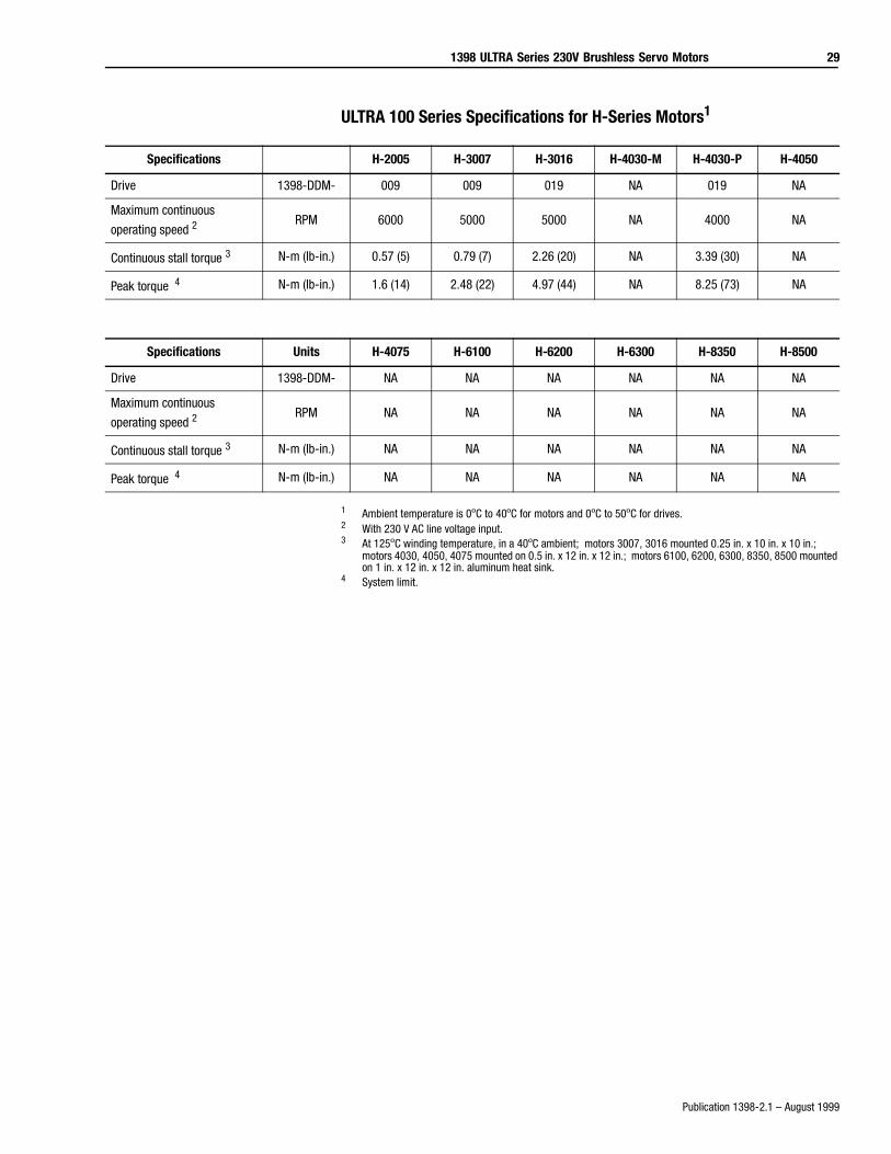
ULTRA 100 Series Specifications for H-Series Motors1
1 Ambient temperature is 0ºC to 40ºC for motors and 0ºC to 50ºC for drives.2 With 230 V AC line voltage input.3 At 125ºC winding temperature, in a 40ºC ambient; motors 3007, 3016 mounted 0.25 in. x 10 in. x 10 in.;
motors 4030, 4050, 4075 mounted on 0.5 in. x 12 in. x 12 in.; motors 6100, 6200, 6300, 8350, 8500 mounted on 1 in. x 12 in. x 12 in. aluminum heat sink.
4 System limit.
Specifications H-2005 H-3007 H-3016 H-4030-M H-4030-P H-4050
Drive 1398-DDM- 009 009 019 NA 019 NA
Maximum continuous
operating speed 2RPM 6000 5000 5000 NA 4000 NA
Continuous stall torque 3 N-m (lb-in.) 0.57 (5) 0.79 (7) 2.26 (20) NA 3.39 (30) NA
Peak torque 4 N-m (lb-in.) 1.6 (14) 2.48 (22) 4.97 (44) NA 8.25 (73) NA
Specifications Units H-4075 H-6100 H-6200 H-6300 H-8350 H-8500
Drive 1398-DDM- NA NA NA NA NA NA
Maximum continuous
operating speed 2RPM NA NA NA NA NA NA
Continuous stall torque 3 N-m (lb-in.) NA NA NA NA NA NA
Peak torque 4 N-m (lb-in.) NA NA NA NA NA NA
30 1398 ULTRA Series 230V Brushless Servo Motors
Publication 1398-2.1 – August 1999
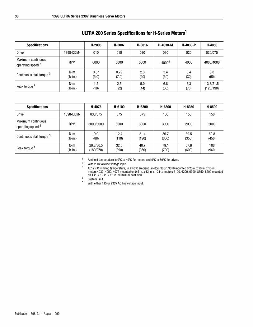
ULTRA 200 Series Specifications for H-Series Motors1
1 Ambient temperature is 0ºC to 40ºC for motors and 0ºC to 50ºC for drives.2 With 230V AC line voltage input.3 At 125ºC winding temperature, in a 40ºC ambient; motors 3007, 3016 mounted 0.25in. x 10 in. x 10 in.;
motors 4030, 4050, 4075 mounted on 0.5 in. x 12 in. x 12 in.; motors 6100, 6200, 6300, 8350, 8500 mounted on 1 in. x 12 in. x 12 in. aluminum heat sink.
4 System limit.5 With either 115 or 230V AC line voltage input.
Specifications H-2005 H-3007 H-3016 H-4030-M H-4030-P H-4050
Drive 1398-DDM- 010 010 020 030 020 030/075
Maximum continuous
operating speed 2RPM 6000 5000 5000 40005 4000 4000/4000
Continuous stall torque 3N-m
(lb-in.)0.57(5.0)
0.79(7.0)
2.3(20)
3.4(30)
3.4(30)
6.8(60)
Peak torque 4N-m
(lb-in.)1.2(10)
2.5(22)
5.0(44)
6.8(60)
8.3(73)
13.6/21.5(120/190)
Specifications H-4075 H-6100 H-6200 H-6300 H-8350 H-8500
Drive 1398-DDM- 030/075 075 075 150 150 150
Maximum continuous
operating speed 2RPM 3000/3000 3000 3000 3000 2000 2000
Continuous stall torque 3N-m
(lb-in.)9.9(88)
12.4(110)
21.4(190)
36.7(300)
39.5(350)
50.8(450)
Peak torque 4N-m
(lb-in.)20.3/30.5(180/270)
32.8(290)
40.7(360)
79.1(700)
67.8(600)
108(960)
1398 ULTRA Series 230V Brushless Servo Motors 31
Publication 1398-2.1 – August 1999
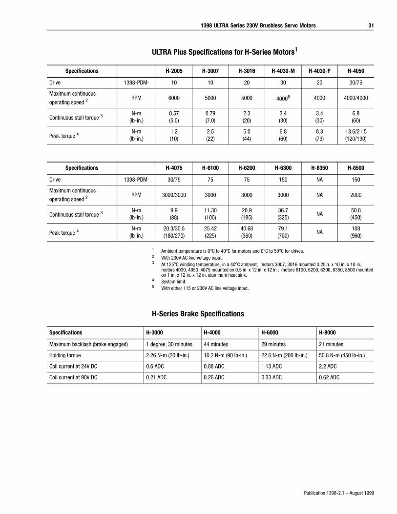
ULTRA Plus Specifications for H-Series Motors1
1 Ambient temperature is 0ºC to 40ºC for motors and 0ºC to 50ºC for drives.2 With 230V AC line voltage input.3 At 125ºC winding temperature, in a 40ºC ambient; motors 3007, 3016 mounted 0.25in. x 10 in. x 10 in.;
motors 4030, 4050, 4075 mounted on 0.5 in. x 12 in. x 12 in.; motors 6100, 6200, 6300, 8350, 8500 mounted on 1 in. x 12 in. x 12 in. aluminum heat sink.
4 System limit.5 With either 115 or 230V AC line voltage input.
H-Series Brake Specifications
Specifications H-2005 H-3007 H-3016 H-4030-M H-4030-P H-4050
Drive 1398-PDM- 10 10 20 30 20 30/75
Maximum continuous
operating speed 2RPM 6000 5000 5000 40005 4000 4000/4000
Continuous stall torque 3N-m
(lb-in.)0.57(5.0)
0.79(7.0)
2.3(20)
3.4(30)
3.4(30)
6.8(60)
Peak torque 4N-m
(lb-in.)1.2(10)
2.5(22)
5.0(44)
6.8(60)
8.3(73)
13.6/21.5(120/190)
Specifications H-4075 H-6100 H-6200 H-6300 H-8350 H-8500
Drive 1398-PDM- 30/75 75 75 150 NA 150
Maximum continuous
operating speed 2RPM 3000/3000 3000 3000 3000 NA 2000
Continuous stall torque 3N-m
(lb-in.)9.9(88)
11.30(100)
20.9(185)
36.7(325)
NA50.8(450)
Peak torque 4N-m
(lb-in.)20.3/30.5(180/270)
25.42(225)
40.68(360)
79.1(700)
NA108(960)
Specifications H-3000 H-4000 H-6000 H-8000
Maximum backlash (brake engaged) 1 degree, 30 minutes 44 minutes 29 minutes 21 minutes
Holding torque 2.26 N-m (20 lb-in.) 10.2 N-m (90 lb-in.) 22.6 N-m (200 lb-in.) 50.8 N-m (450 lb-in.)
Coil current at 24V DC 0.6 ADC 0.88 ADC 1.13 ADC 2.2 ADC
Coil current at 90V DC 0.21 ADC 0.26 ADC 0.33 ADC 0.62 ADC
32 1398 ULTRA Series 230V Brushless Servo Motors
Publication 1398-2.1 – August 1999
Brake Motor Application Guidelines
The brakes offered as options on these servo motors are holding brakes. They
are designed to hold the motor shaft at 0 rpm for up to the rated brake holding
torque. The brakes are spring-set type, and release when voltage is applied to
the brake coil.
The brakes are not designed for stopping rotation of the motor shaft. Servo
drive inputs should be used to stop motor shaft rotation. The recommended
method of stopping motor shaft rotation is to command the servo drive to
decelerate the motor to 0 rpm, and engage the brake after the servo drive has
decelerated the motor to 0 rpm.
If system main power fails, the brakes can withstand use as stopping brakes.
However, use of the brakes as stopping brakes creates rotational mechanical
backlash that is potentially damaging to the system, increases brake pad wear
and reduces brake life. The brakes are not designed nor are they intended to be
used as a safety device.
A separate power source is required to disengage the brake. This power
source may be controlled by the servo motor controls, in addition to manual
operator controls.
H-Series Standard Motors Dimensions
Dimensions Thread Thread/Depth
H-2000 M3 x 0.5 mm 10 mm/0.39 in.
H-3000 M4 x 0.7 mm 10 mm/0.39 in.
H-4000 M6 x 1.0 mm 15 mm/0.59 in.
H-6000 M8 x 1.25 mm 20 mm/0.79 in.
H-8000 M8 x 1.25 mm 20 mm/0.79 in.
1398 ULTRA Series 230V Brushless Servo Motors 33
Publication 1398-2.1 – August 1999
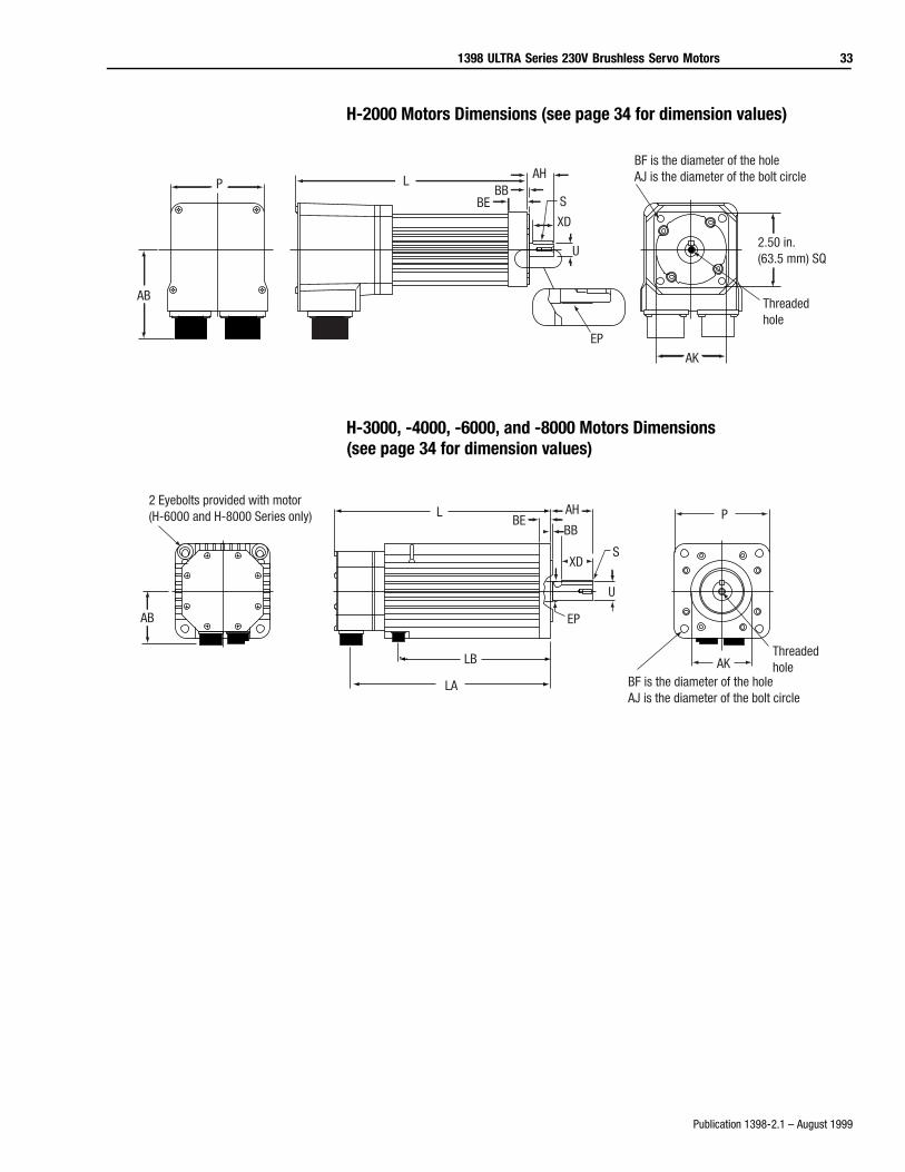
H-2000 Motors Dimensions (see page 34 for dimension values)
H-3000, -4000, -6000, and -8000 Motors Dimensions(see page 34 for dimension values)
P
AB
AHBB
BE
EP
L
S
U
XD
AK
Threadedhole
BF is the diameter of the holeAJ is the diameter of the bolt circle
2.50 in. (63.5 mm) SQ
2 Eyebolts provided with motor(H-6000 and H-8000 Series only)
AB
AH
BBBE
EP
L
S
U
XD
AK
P
Threadedhole
BF is the diameter of the holeAJ is the diameter of the bolt circle
LA
LB
34 1398 ULTRA Series 230V Brushless Servo Motors
Publication 1398-2.1 – August 1999
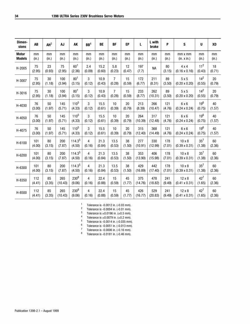
1 Tolerance is -0.0012 in. (-0.03 mm).2 Tolerance is -0.0004 in. (-0.01 mm).3 Tolerance is ±0.0196 in. (±0.5 mm).4 Tolerance is ±0.0079 in. (±0.2 mm).5 Tolerance is -0.0014 in. (-0.035 mm).6 Tolerance is -0.0051 in. (-0.013 mm).7 Tolerance is -0.0006 in. (-0.16 mm).8 Tolerance is -0.0181 in. (-0.46 mm).
Dimen-sions
AB AH3 AJ AK BB4 BE BF EP LL with brake
P S U XD
Motor Models
mm(in.)
mm(in.)
mm(in.)
mm(in.)
mm(in.)
mm(in.)
mm(in.)
mm(in.)
mm(in.)
mm(in.)
mm(in.)
mm x mm(in. x in.)
mm(in.)
mm(in.)
H-2005 75(2.95)
23(0.93)
75(2.95)
601
(2.36)2.4
(0.09)15.2
(0.60)5.8
(0.23)12
(0.47)197(7.7)
NA 80(3.15)
4 x 4(0.16 x 0.16)
112
(0.43)18
(0.71)
H-3007 75(2.95)
30(1.18)
100(3.94)
801
(3.15)3
(0.12)10.9
(0.43)7
(0.28)15
(0.59)172
(6.77)211
(8.31)89
(3.50)5 x 5
(0.20 x 0.20)142
(0.55)20
(0.79)
H-3016 75(2.95)
30(1.18)
100(3.94)
801
(3.15)3
(0.12)10.9
(0.43)7
(0.28)15
(0.59)233
(8.77)262
(10.31)89
(3.50)5 x 5
(0.20 x 0.20)142
(0.55)20
(0.79)
H-4030 76(3.00)
50(1.97)
145(5.71)
1105
(4.33)3
(0.12)15.5
(0.61)10
(0.39)20
(0.79)213
(8.39)266
(10.47)121
(4.76)6 x 6
(0.24 x 0.24)196
(0.75)40
(1.57)
H-4050 76(3.00)
50(1.97)
145(5.71)
1105
(4.33)3
(0.12)15.5
(0.61)10
(0.39)20
(0.79)264
(10.39)317
(12.48)121
(4.76)6 x 6
(0.24 x 0.24)196
(0.75)40
(1.57)
H-4075 76(3.00)
50(1.97)
145(5.71)
1105
(4.33)3
(0.12)15.5
(0.61)10
(0.39)20
(0.79)315
(12.40)368
(14.49)121
(4.76)6 x 6
(0.24 x 0.24)196
(0.75)40
(1.57)
H-6100 101(4.00)
80(3.15)
200(7.87)
114.35
(4.50)4
(0.16)21.3
(0.84)13.5
(0.53)38
(1.50)277
(10.91)330
(12.99)178
(7.01)10 x 8
(0.39 x 0.31)357
(1.38)60
(2.36)
H-6200 101(4.00)
80(3.15)
200(7.87)
114.35
(4.50)4
(0.16)21.3
(0.84)13.5
(0.53)38
(1.50)353
(13.90)406
(15.98)178
(7.01)10 x 8
(0.39 x 0.31)357
(1.38)60
(2.36)
H-6300 101(4.00)
80(3.15)
200(7.87)
114.35
(4.50)4
(0.16)21.3
(0.84)13.5
(0.53)38
(1.50)429
(16.89)442
(17.40)178
(7.01)10 x 8
(0.39 x 0.31)357
(1.38)60
(2.36)
H-8350 112(4.41)
85(3.35)
265(10.43)
2308
(9.06)4
(0.16)22.4
(0.88)15
(0.59)45
(1.77)375
(14.76)478
(18.82)241
(9.49)12 x 8
(0.41 x 0.31)427
(1.65)60
(2.36)
H-8500 112(4.41)
85(3.35)
265(10.43)
2308
(9.06)4
(0.16)22.4
(0.88)15
(0.59)45
(1.77)426
(16.77)529
(20.83)241
(9.49)12 x 8
(0.41 x 0.31)427
(1.65)60
(2.36)
1398 ULTRA Series 230V Brushless Servo Motors 35
Publication 1398-2.1 – August 1999
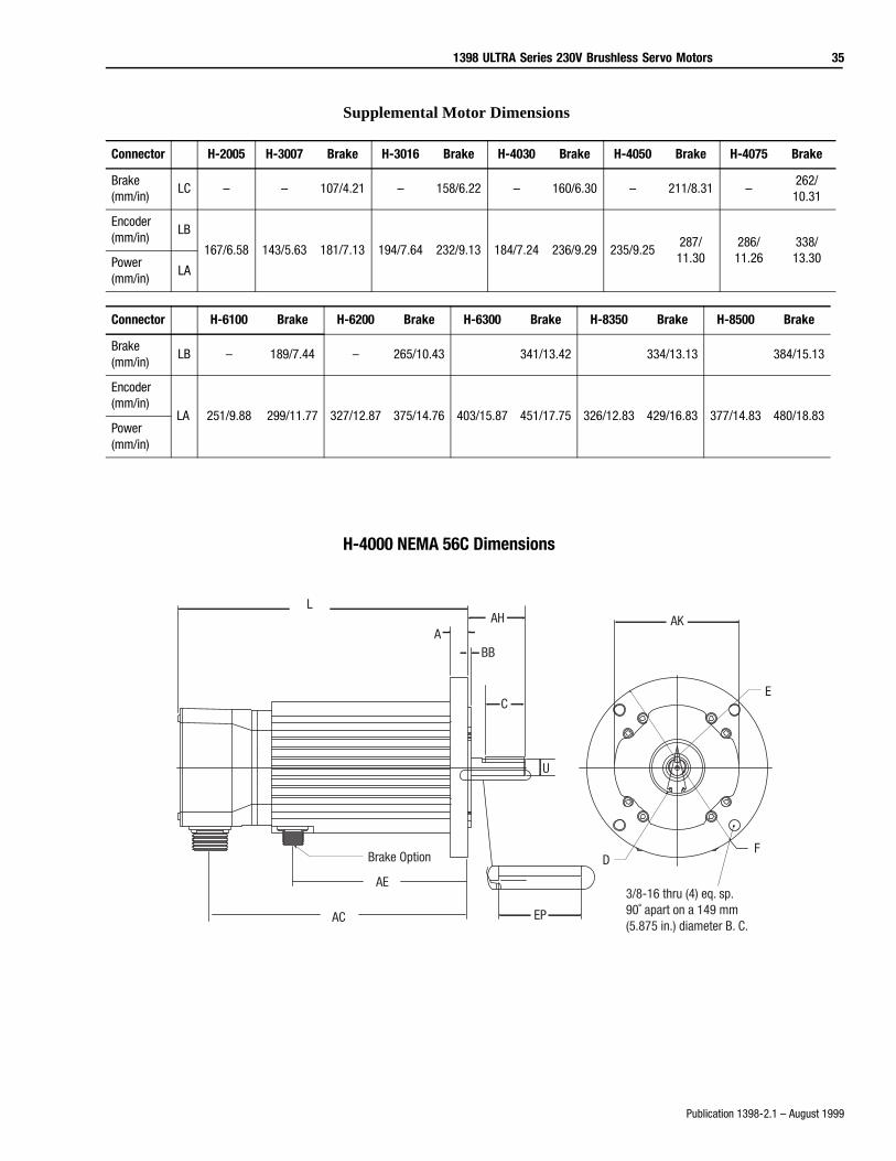
Supplemental Motor Dimensions
H-4000 NEMA 56C Dimensions
Connector H-2005 H-3007 Brake H-3016 Brake H-4030 Brake H-4050 Brake H-4075 Brake
Brake(mm/in)
LC – – 107/4.21 – 158/6.22 – 160/6.30 – 211/8.31 –262/10.31
Encoder(mm/in)
LB
167/6.58 143/5.63 181/7.13 194/7.64 232/9.13 184/7.24 236/9.29 235/9.25287/11.30
286/11.26
338/13.30Power
(mm/in)LA
Connector H-6100 Brake H-6200 Brake H-6300 Brake H-8350 Brake H-8500 Brake
Brake(mm/in)
LB – 189/7.44 – 265/10.43 341/13.42 334/13.13 384/15.13
Encoder(mm/in)
LA 251/9.88 299/11.77 327/12.87 375/14.76 403/15.87 451/17.75 326/12.83 429/16.83 377/14.83 480/18.83Power(mm/in)
L
Brake Option
ABB
AH
C
U
EP
AK
E
FD
3/8-16 thru (4) eq. sp.90˚ apart on a 149 mm (5.875 in.) diameter B. C.
AC
AE
36 1398 ULTRA Series 230V Brushless Servo Motors
Publication 1398-2.1 – August 1999
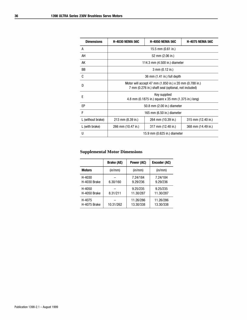
Supplemental Motor Dimensions
Dimensions H-4030 NEMA 56C H-4050 NEMA 56C H-4075 NEMA 56C
A 15.5 mm (0.61 in.)
AH 52 mm (2.06 in.)
AK 114.3 mm (4.500 in.) diameter
BB 3 mm (0.12 in.)
C 36 mm (1.41 in.) full depth
DMotor will accept 47 mm (1.850 in.) x 20 mm (0.788 in.)
7 mm (0.276 in.) shaft seal (optional, not included)
EKey supplied
4.8 mm (0.1875 in.) square x 35 mm (1.375 in.) long)
EP 50.8 mm (2.00 in.) diameter
F 165 mm (6.50 in.) diameter
L (without brake) 213 mm (8.39 in.) 264 mm (10.39 in.) 315 mm (12.40 in.)
L (with brake) 266 mm (10.47 in.) 317 mm (12.48 in.) 368 mm (14.49 in.)
U 15.9 mm (0.625 in.) diameter
Brake (AE) Power (AC) Encoder (AC)
Motors (in/mm) (in/mm) (in/mm)
H-4030H-4030 Brake
–6.30/160
7.24/1849.29/236
7.24/1849.29/236
H-4050H-4050 Brake
–8.31/211
9.25/23511.30/287
9.25/23511.30/287
H-4075H-4075 Brake
–10.31/262
11.26/28613.30/338
11.26/28613.30/338
1398 ULTRA Series 230V Brushless Servo Motors 37
Publication 1398-2.1 – August 1999
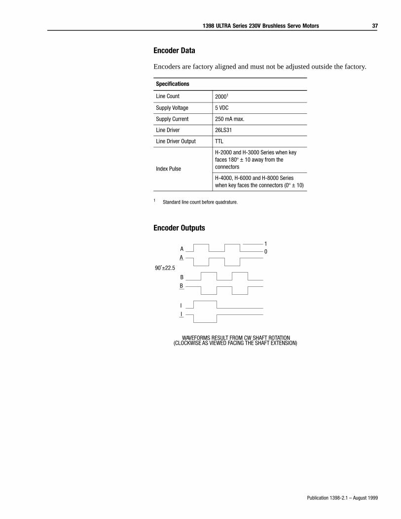
Encoder Data
Encoders are factory aligned and must not be adjusted outside the factory.
1 Standard line count before quadrature.
Encoder Outputs
Specifications
Line Count 20001
Supply Voltage 5 VDC
Supply Current 250 mA max.
Line Driver 26LS31
Line Driver Output TTL
Index Pulse
H-2000 and H-3000 Series when key faces 180º ± 10 away from the connectors
H-4000, H-6000 and H-8000 Series when key faces the connectors (0º ± 10)
10A
B
I
I
B
A
90˚±22.5
WAVEFORMS RESULT FROM CW SHAFT ROTATION(CLOCKWISE AS VIEWED FACING THE SHAFT EXTENSION)
38 1398 ULTRA Series 230V Brushless Servo Motors
Publication 1398-2.1 – August 1999
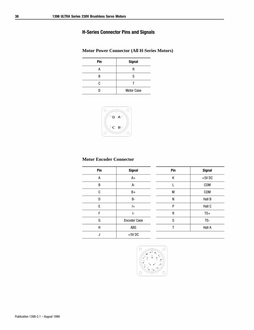
H-Series Connector Pins and Signals
Motor Power Connector (All H-Series Motors)
Motor Encoder Connector
Pin Signal
A R
B S
C T
D Motor Case
Pin Signal Pin Signal
A A+ K +5V DC
B A- L COM
C B+ M COM
D B- N Hall B
E I+ P Hall C
F I- R TS+
G Encoder Case S TS-
H ABS T Hall A
J +5V DC
P0002
A
BC
D
A B
C
D
E
FGH
J
K
L
M
N P
RS
T
P0001
1398 ULTRA Series 230V Brushless Servo Motors 39
Publication 1398-2.1 – August 1999
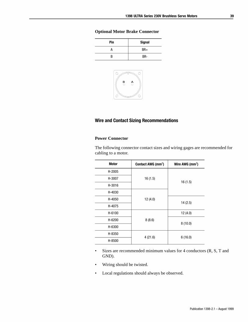
Optional Motor Brake Connector
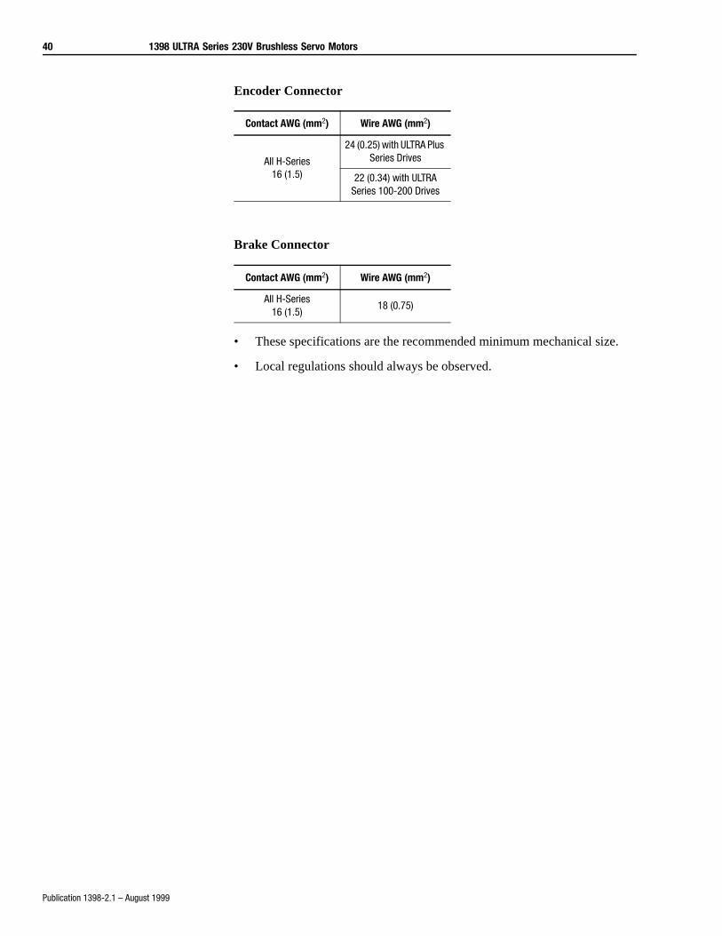
Wire and Contact Sizing Recommendations
Power Connector
The following connector contact sizes and wiring gages are recommended for cabling to a motor.
• Sizes are recommended minimum values for 4 conductors (R, S, T and GND).
• Wiring should be twisted.
• Local regulations should always be observed.
Pin Signal
A BR+
B BR-
Motor Contact AWG (mm2) Wire AWG (mm2)
H-2005
16 (1.5)16 (1.5)
H-3007
H-3016
H-4030
12 (4.0)H-405014 (2.5)
H-4075
H-6100
8 (8.6)
12 (4.0)
H-62008 (10.0)
H-6300
H-83504 (21.6) 6 (16.0)
H-8500
B A
P0003
40 1398 ULTRA Series 230V Brushless Servo Motors
Publication 1398-2.1 – August 1999
Encoder Connector
Brake Connector
• These specifications are the recommended minimum mechanical size.
• Local regulations should always be observed.
Contact AWG (mm2) Wire AWG (mm2)
All H-Series16 (1.5)
24 (0.25) with ULTRA Plus Series Drives
22 (0.34) with ULTRA Series 100-200 Drives
Contact AWG (mm2) Wire AWG (mm2)
All H-Series16 (1.5)
18 (0.75)
1398 ULTRA Series 230V Brushless Servo Motors 41
Publication 1398-2.1 – August 1999
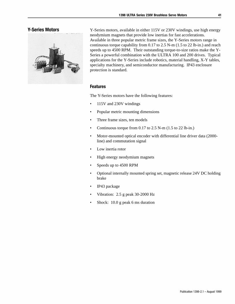
Y-Series Motors Y-Series motors, available in either 115V or 230V windings, use high energy neodymium magnets that provide low inertias for fast accelerations. Available in three popular metric frame sizes, the Y-Series motors range in continuous torque capability from 0.17 to 2.5 N-m (1.5 to 22 lb-in.) and reach speeds up to 4500 RPM. Their outstanding torque-to-size ratios make the Y-Series a powerful combination with the ULTRA 100 and 200 drives. Typical applications for the Y-Series include robotics, material handling, X-Y tables, specialty machinery, and semiconductor manufacturing. IP43 enclosure protection is standard.
Features
The Y-Series motors have the following features:
• 115V and 230V windings
• Popular metric mounting dimensions
• Three frame sizes, ten models
• Continuous torque from 0.17 to 2.5 N-m (1.5 to 22 lb-in.)
• Motor-mounted optical encoder with differential line driver data (2000-line) and commutation signal
• Low inertia rotor
• High energy neodymium magnets
• Speeds up to 4500 RPM
• Optional internally mounted spring set, magnetic release 24V DC holding brake
• IP43 package
• Vibration: 2.5 g peak 30-2000 Hz
• Shock: 10.0 g peak 6 ms duration
42 1398 ULTRA Series 230V Brushless Servo Motors
Publication 1398-2.1 – August 1999
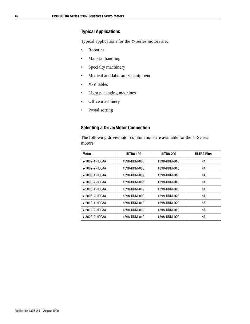
Typical Applications
Typical applications for the Y-Series motors are:
• Robotics
• Material handling
• Specialty machinery
• Medical and laboratory equipment
• X-Y tables
• Light packaging machines
• Office machinery
• Postal sorting
Selecting a Drive/Motor Connection
The following drive/motor combinations are available for the Y-Series motors:
Motor ULTRA 100 ULTRA 200 ULTRA Plus
Y-1002-1-H00AA 1398-DDM-005 1398-DDM-010 NA
Y-1002-2-H00AA 1398-DDM-005 1398-DDM-010 NA
Y-1003-1-H00AA 1398-DDM-009 1398-DDM-010 NA
Y-1003-2-H00AA 1398-DDM-005 1398-DDM-010 NA
Y-2006-1-H00AA 1398-DDM-019 1398-DDM-010 NA
Y-2006-2-H00AA 1398-DDM-009 1398-DDM-020 NA
Y-2012-1-H00AA 1398-DDM-019 1398-DDM-020 NA
Y-2012-2-H00AA 1398-DDM-009 1398-DDM-010 NA
Y-3023-2-H00AA 1398-DDM-019 1398-DDM-020 NA
1398 ULTRA Series 230V Brushless Servo Motors 43
Publication 1398-2.1 – August 1999
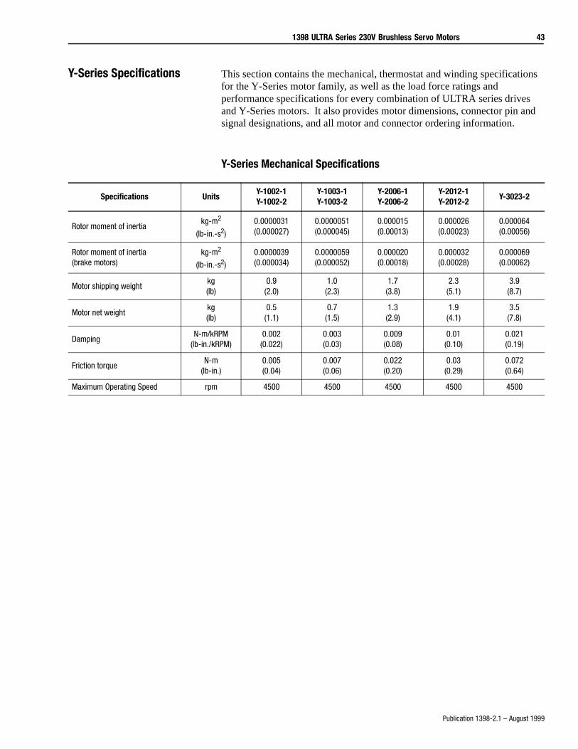
Y-Series Specifications This section contains the mechanical, thermostat and winding specifications for the Y-Series motor family, as well as the load force ratings and performance specifications for every combination of ULTRA series drives and Y-Series motors. It also provides motor dimensions, connector pin and signal designations, and all motor and connector ordering information.
Y-Series Mechanical Specifications
Specifications UnitsY-1002-1Y-1002-2
Y-1003-1Y-1003-2
Y-2006-1Y-2006-2
Y-2012-1Y-2012-2
Y-3023-2
Rotor moment of inertiakg-m2
(lb-in.-s2)
0.0000031(0.000027)
0.0000051(0.000045)
0.000015(0.00013)
0.000026(0.00023)
0.000064(0.00056)
Rotor moment of inertia(brake motors)
kg-m2
(lb-in.-s2)
0.0000039(0.000034)
0.0000059(0.000052)
0.000020(0.00018)
0.000032(0.00028)
0.000069(0.00062)
Motor shipping weightkg(lb)
0.9(2.0)
1.0(2.3)
1.7(3.8)
2.3(5.1)
3.9(8.7)
Motor net weightkg(lb)
0.5(1.1)
0.7(1.5)
1.3(2.9)
1.9(4.1)
3.5(7.8)
DampingN-m/kRPM
(lb-in./kRPM)0.002
(0.022)0.003(0.03)
0.009(0.08)
0.01(0.10)
0.021(0.19)
Friction torqueN-m
(lb-in.)0.005(0.04)
0.007(0.06)
0.022(0.20)
0.03(0.29)
0.072(0.64)
Maximum Operating Speed rpm 4500 4500 4500 4500 4500
44 1398 ULTRA Series 230V Brushless Servo Motors
Publication 1398-2.1 – August 1999
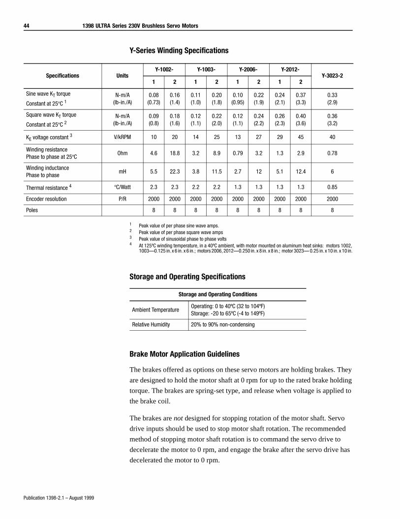
Y-Series Winding Specifications
1 Peak value of per phase sine wave amps.2 Peak value of per phase square wave amps3 Peak value of sinusoidal phase to phase volts4 At 125ºC winding temperature, in a 40ºC ambient, with motor mounted on aluminum heat sinks: motors 1002,
1003—0.125 in. x 6 in. x 6 in.; motors 2006, 2012—0.250 in. x 8 in. x 8 in.; motor 3023— 0.25 in. x 10 in. x 10 in.
Storage and Operating Specifications
Brake Motor Application Guidelines
The brakes offered as options on these servo motors are holding brakes. They
are designed to hold the motor shaft at 0 rpm for up to the rated brake holding
torque. The brakes are spring-set type, and release when voltage is applied to
the brake coil.
The brakes are not designed for stopping rotation of the motor shaft. Servo
drive inputs should be used to stop motor shaft rotation. The recommended
method of stopping motor shaft rotation is to command the servo drive to
decelerate the motor to 0 rpm, and engage the brake after the servo drive has
decelerated the motor to 0 rpm.
Specifications UnitsY-1002- Y-1003- Y-2006- Y-2012-
Y-3023-21 2 1 2 1 2 1 2
Sine wave KT torque
Constant at 25ºC 1N-m/A
(lb-in./A)0.08
(0.73)0.16(1.4)
0.11(1.0)
0.20(1.8)
0.10(0.95)
0.22(1.9)
0.24(2.1)
0.37(3.3)
0.33(2.9)
Square wave KT torque
Constant at 25ºC 2N-m/A
(lb-in./A)0.09(0.8)
0.18(1.6)
0.12(1.1)
0.22(2.0)
0.12(1.1)
0.24(2.2)
0.26(2.3)
0.40(3.6)
0.36(3.2)
KE voltage constant 3 V/kRPM 10 20 14 25 13 27 29 45 40
Winding resistance Phase to phase at 25ºC
Ohm 4.6 18.8 3.2 8.9 0.79 3.2 1.3 2.9 0.78
Winding inductance Phase to phase
mH 5.5 22.3 3.8 11.5 2.7 12 5.1 12.4 6
Thermal resistance 4 ºC/Watt 2.3 2.3 2.2 2.2 1.3 1.3 1.3 1.3 0.85
Encoder resolution P/R 2000 2000 2000 2000 2000 2000 2000 2000 2000
Poles 8 8 8 8 8 8 8 8 8
Storage and Operating Conditions
Ambient TemperatureOperating: 0 to 40ºC (32 to 104ºF)Storage: -20 to 65ºC (-4 to 149ºF)
Relative Humidity 20% to 90% non-condensing
1398 ULTRA Series 230V Brushless Servo Motors 45
Publication 1398-2.1 – August 1999
If system main power fails, the brakes can withstand use as stopping brakes.
However, use of the brakes as stopping brakes creates rotational mechanical
backlash that is potentially damaging to the system, increases brake pad wear
and reduces brake life. The brakes are not designed nor are they intended to be
used as a safety device.
A separate power source is required to disengage the brake. This power
source may be controlled by the servo motor controls, in addition to manual
operator controls.
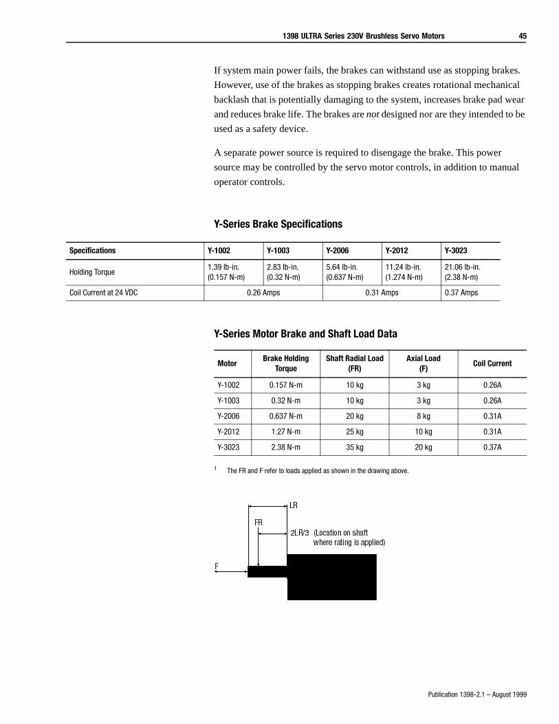
Y-Series Brake Specifications
Y-Series Motor Brake and Shaft Load Data
1 The FR and F refer to loads applied as shown in the drawing above.
Specifications Y-1002 Y-1003 Y-2006 Y-2012 Y-3023
Holding Torque1.39 lb-in.(0.157 N-m)
2.83 lb-in. (0.32 N-m)
5.64 lb-in. (0.637 N-m)
11.24 lb-in. (1.274 N-m)
21.06 lb-in.(2.38 N-m)
Coil Current at 24 VDC 0.26 Amps 0.31 Amps 0.37 Amps
MotorBrake Holding
TorqueShaft Radial Load
(FR)Axial Load
(F)Coil Current
Y-1002 0.157 N-m 10 kg 3 kg 0.26A
Y-1003 0.32 N-m 10 kg 3 kg 0.26A
Y-2006 0.637 N-m 20 kg 8 kg 0.31A
Y-2012 1.27 N-m 25 kg 10 kg 0.31A
Y-3023 2.38 N-m 35 kg 20 kg 0.37A
46 1398 ULTRA Series 230V Brushless Servo Motors
Publication 1398-2.1 – August 1999
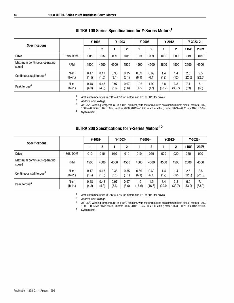
ULTRA 100 Series Specifications for Y-Series Motors1
1 Ambient temperature is 0ºC to 40ºC for motors and 0ºC to 50ºC for drives.2 At drive input voltage.3 At 125ºC winding temperature, in a 40ºC ambient, with motor mounted on aluminum heat sinks: motors 1002,
1003—0.125 in. x 6 in. x 6 in.; motors 2006, 2012—0.250 in. x 8 in. x 8 in.; motor 3023— 0.25 in. x 10 in. x 10 in. 4 System limit.
ULTRA 200 Specifications for Y-Series Motors1 2
1 Ambient temperature is 0ºC to 40ºC for motors and 0ºC to 50ºC for drives.2 At drive input voltage.3 At 125ºC winding temperature, in a 40ºC ambient, with motor mounted on aluminum heat sinks: motors 1002,
1003—0.125 in. x 6 in. x 6 in.; motors 2006, 2012—0.250 in. x 8 in. x 8 in.; motor 3023— 0.25 in. x 10 in. x 10 in. 4 System limit.
SpecificationsY-1002- Y-1003- Y-2006- Y-2012- Y-3023-2
1 2 1 2 1 2 1 2 115V 230V
Drive 1398-DDM- 005 005 009 005 019 009 019 009 019 019
Maximum continuous operating speed
RPM 4500 4500 4500 4500 4500 4500 3800 4500 2500 4500
Continuous stall torque3 N-m(lb-in.)
0.17(1.5)
0.17(1.5)
0.35(3.1)
0.35(3.1)
0.69(6.1)
0.69(6.1)
1.4(12)
1.4(12)
2.5(22.5)
2.5(22.5)
Peak torque4 N-m(lb-in.)
0.48(4.3)
0.48(4.3)
0.97(8.6)
0.97(8.6)
1.92(17)
1.92(17)
3.8(33.7)
3.8(33.7)
7.1(63)
7.1(63)
SpecificationsY-1002- Y-1003- Y-2006- Y-2012- Y-3023-
1 2 1 2 1 2 1 2 115V 230V
Drive 1398-DDM- 010 010 010 010 010 020 020 020 020 020
Maximum continuous operating speed
RPM 4500 4500 4500 4500 4500 4500 4500 4500 2500 4500
Continuous stall torque3 N-m(lb-in.)
0.17(1.5)
0.17(1.5)
0.35(3.1)
0.35(3.1)
0.69(6.1)
0.69(6.1)
1.4(12)
1.4(12)
2.5(22.5)
2.5(22.5)
Peak torque4 N-m(lb-in.)
0.48(4.3)
0.48(4.3)
0.97(8.6)
0.97(8.6)
1.9(16.6)
1.9(16.6)
3.4(30.0)
3.8(33.7)
6.0(53.0)
7.1(63.0)
1398 ULTRA Series 230V Brushless Servo Motors 47
Publication 1398-2.1 – August 1999
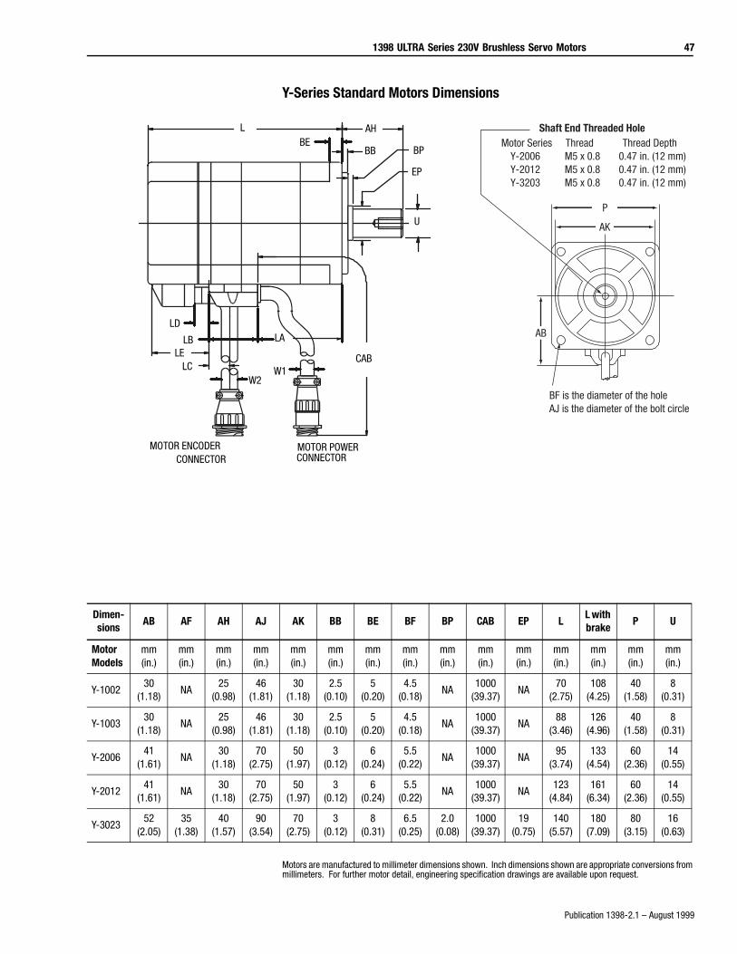
Y-Series Standard Motors Dimensions
Motors are manufactured to millimeter dimensions shown. Inch dimensions shown are appropriate conversions from millimeters. For further motor detail, engineering specification drawings are available upon request.
Shaft End Threaded Hole
AB
AK
P
BF is the diameter of the holeAJ is the diameter of the bolt circle
Motor Series Thread Thread DepthY-2006 M5 x 0.8 0.47 in. (12 mm)Y-2012 M5 x 0.8 0.47 in. (12 mm)Y-3203 M5 x 0.8 0.47 in. (12 mm)
MOTOR ENCODERCONNECTOR
MOTOR POWERCONNECTOR
U
EP
AH
BBBE
L
LELC
LD
LB LA
W2W1
CAB
BP
Dimen-sions
AB AF AH AJ AK BB BE BF BP CAB EP LL with brake
P U
Motor Models
mm(in.)
mm(in.)
mm(in.)
mm(in.)
mm(in.)
mm(in.)
mm(in.)
mm(in.)
mm(in.)
mm(in.)
mm(in.)
mm(in.)
mm(in.)
mm(in.)
mm(in.)
Y-100230
(1.18)NA
25(0.98)
46(1.81)
30(1.18)
2.5(0.10)
5(0.20)
4.5(0.18)
NA1000
(39.37)NA
70(2.75)
108(4.25)
40(1.58)
8(0.31)
Y-100330
(1.18)NA
25(0.98)
46(1.81)
30(1.18)
2.5(0.10)
5(0.20)
4.5(0.18)
NA1000
(39.37)NA
88(3.46)
126(4.96)
40(1.58)
8(0.31)
Y-200641
(1.61)NA
30(1.18)
70(2.75)
50(1.97)
3(0.12)
6(0.24)
5.5(0.22)
NA1000
(39.37)NA
95(3.74)
133(4.54)
60(2.36)
14(0.55)
Y-201241
(1.61)NA
30(1.18)
70(2.75)
50(1.97)
3(0.12)
6(0.24)
5.5(0.22)
NA1000
(39.37)NA
123(4.84)
161(6.34)
60(2.36)
14(0.55)
Y-302352
(2.05)35
(1.38)40
(1.57)90
(3.54)70
(2.75)3
(0.12)8
(0.31)6.5
(0.25)2.0
(0.08)1000
(39.37)19
(0.75)140
(5.57)180
(7.09)80
(3.15)16
(0.63)
48 1398 ULTRA Series 230V Brushless Servo Motors
Publication 1398-2.1 – August 1999
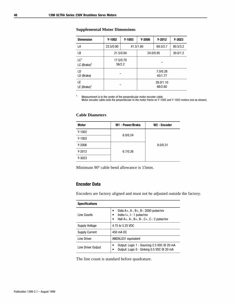
Supplemental Motor Dimensions
1 Measurement is to the center of the perpendicular motor encoder cable. Motor encoder cable exits the perpendicular to the motor frame on Y-1002 and Y-1003 motors (not as shown).
Cable Diameters
Minimum 90º cable bend allowance is 15mm.
Encoder Data
Encoders are factory aligned and must not be adjusted outside the factory.
The line count is standard before quadrature.
Dimension Y-1002 Y-1003 Y-2006 Y-2012 Y-3023
LA 23.5/0.90 41.5/1.60 69.5/2.7 80.5/3.2
LB 21.5/0.84 24.0/0.95 30.0/1.2
LC1
LC (Brake)117.5/0.70
56/2.2–
LDLD (Brake)
–7.0/0.2845/1.77
LELE (Brake)1
–28.0/1.1066/2.60
Motor W1 - Power/Brake W2 - Encoder
Y-10026.0/0.24
8.0/0.31
Y-1003
Y-2006
6.7/0.26Y-2012
Y-3023
Specifications
Line Counts• Data A+, A-, B+, B-: 2000 pulse/rev• Index I+, I-: 1 pulse/rev• Hall A+, A-, B+, B-, C+, C-: 2 pulse/rev
Supply Voltage 4.75 to 5.25 VDC
Supply Current 450 mA DC
Line Driver AM26LS31 equivalent
Line Driver Output• Output: Logic 1 - Sourcing 2.5 VDC @ 20 mA• Output: Logic 0 - Sinking 0.5 VDC @ 20 mA
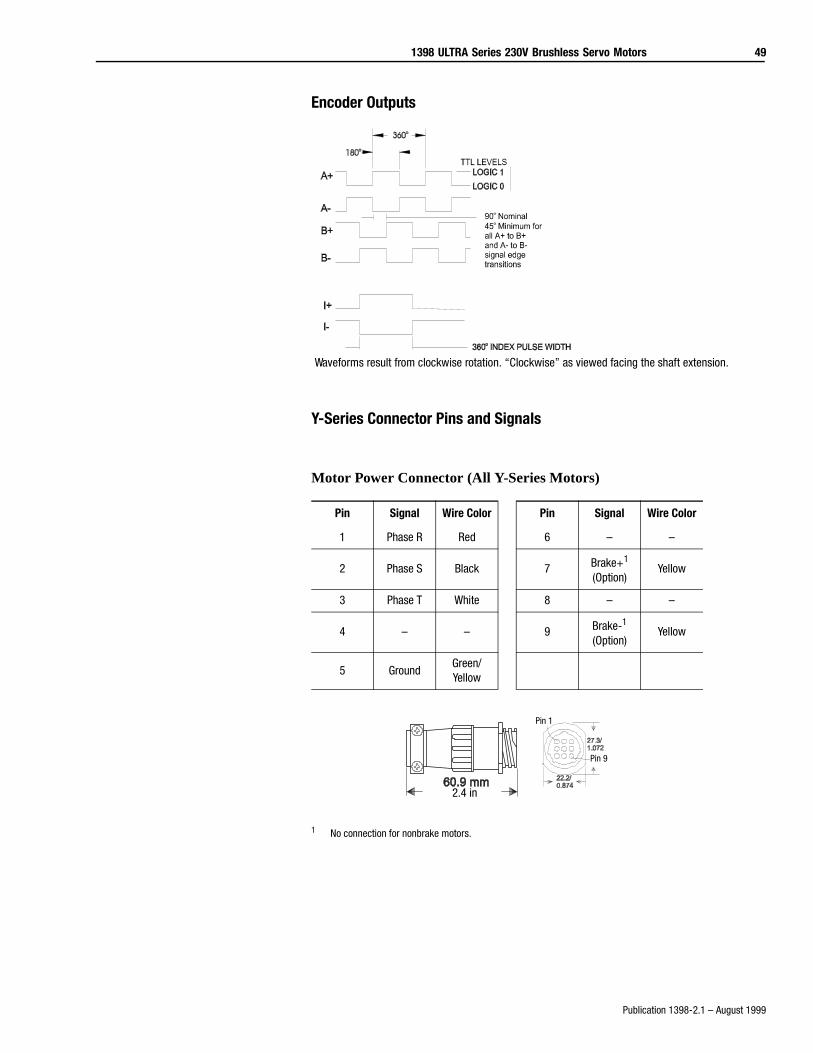
1398 ULTRA Series 230V Brushless Servo Motors 49
Publication 1398-2.1 – August 1999
Encoder Outputs
Y-Series Connector Pins and Signals
Motor Power Connector (All Y-Series Motors)
1 No connection for nonbrake motors.
Pin Signal Wire Color Pin Signal Wire Color
1 Phase R Red 6 – –
2 Phase S Black 7 Brake+1
(Option)Yellow
3 Phase T White 8 – –
4 – – 9 Brake-1
(Option)Yellow
5 GroundGreen/Yellow
Waveforms result from clockwise rotation. “Clockwise” as viewed facing the shaft extension.
Intro
2.4 in
Pin 1
Pin 9
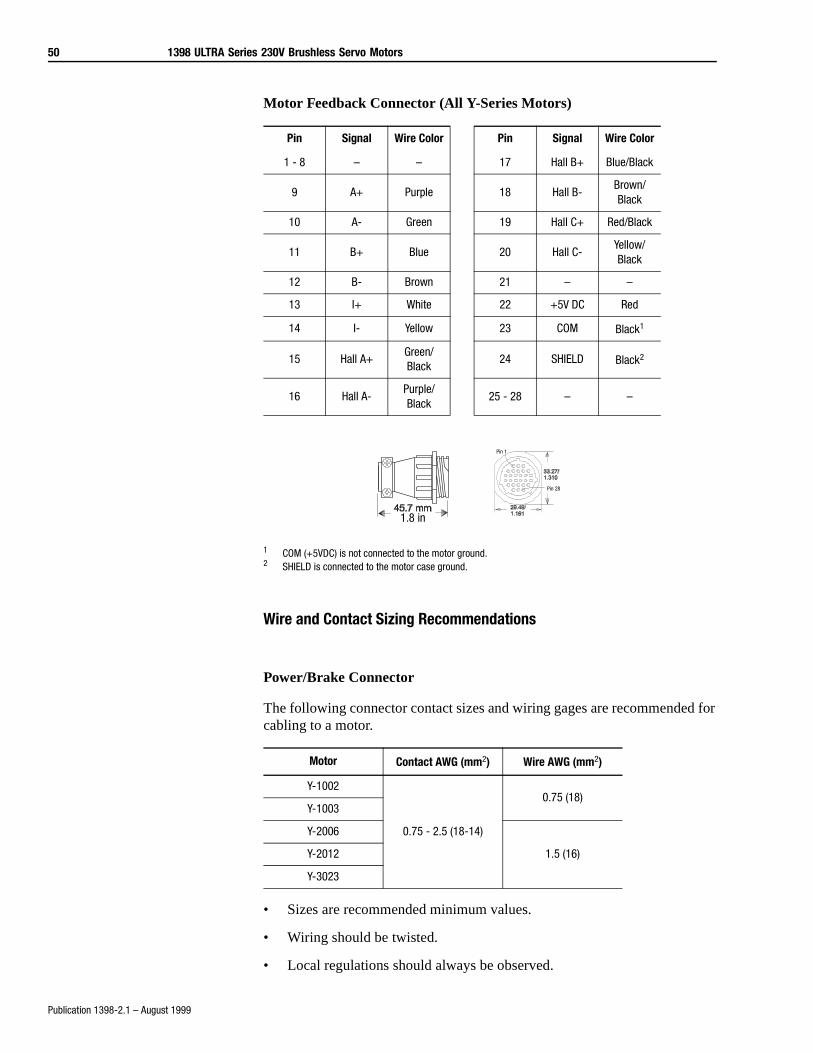
50 1398 ULTRA Series 230V Brushless Servo Motors
Publication 1398-2.1 – August 1999
Motor Feedback Connector (All Y-Series Motors)
1 COM (+5VDC) is not connected to the motor ground.2 SHIELD is connected to the motor case ground.
Wire and Contact Sizing Recommendations
Power/Brake Connector
The following connector contact sizes and wiring gages are recommended for cabling to a motor.
• Sizes are recommended minimum values.
• Wiring should be twisted.
• Local regulations should always be observed.
Pin Signal Wire Color Pin Signal Wire Color
1 - 8 – – 17 Hall B+ Blue/Black
9 A+ Purple 18 Hall B-Brown/Black
10 A- Green 19 Hall C+ Red/Black
11 B+ Blue 20 Hall C-Yellow/Black
12 B- Brown 21 – –
13 I+ White 22 +5V DC Red
14 I- Yellow 23 COM Black1
15 Hall A+Green/Black
24 SHIELD Black2
16 Hall A-Purple/Black
25 - 28 – –
Motor Contact AWG (mm2) Wire AWG (mm2)
Y-1002
0.75 - 2.5 (18-14)
0.75 (18)Y-1003
Y-2006
1.5 (16)Y-2012
Y-3023
1.8 in
Pin 1
Pin 28
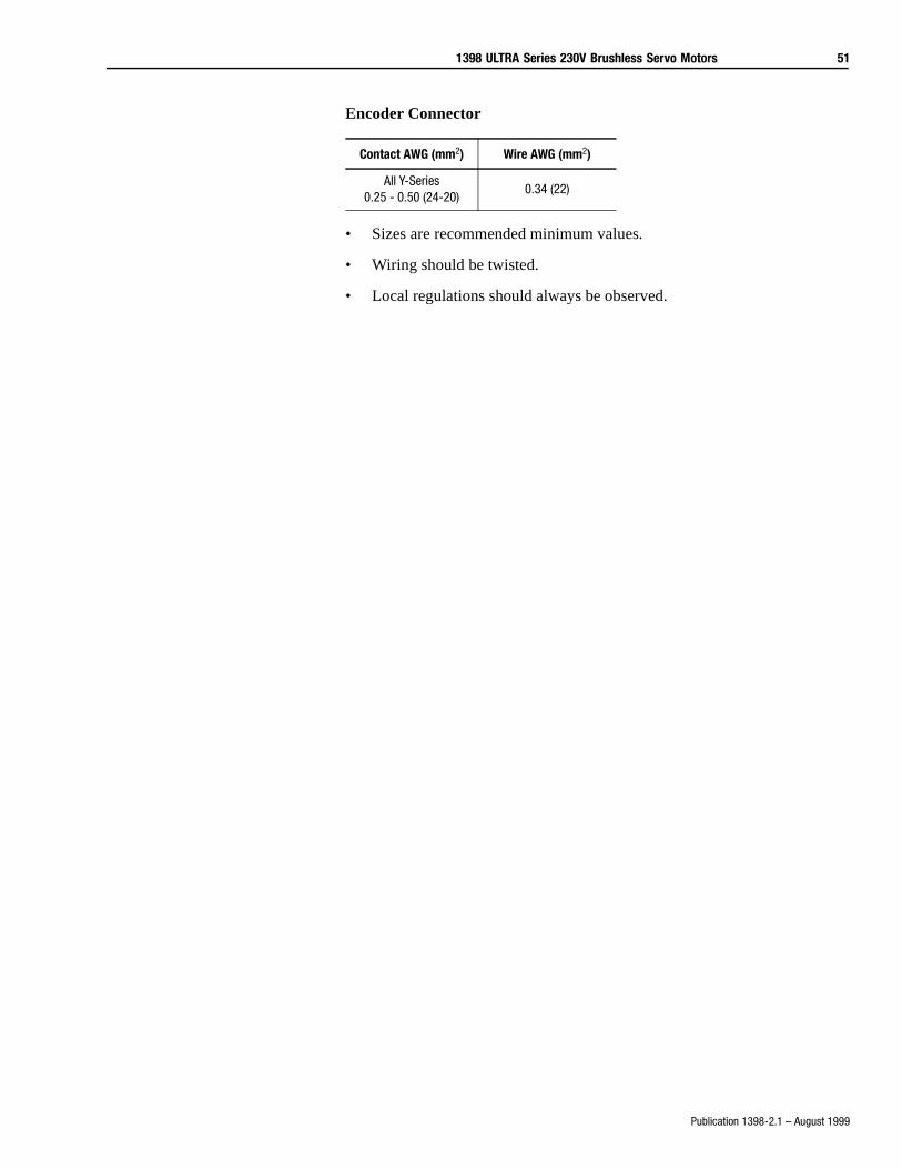
1398 ULTRA Series 230V Brushless Servo Motors 51
Publication 1398-2.1 – August 1999
Encoder Connector
• Sizes are recommended minimum values.
• Wiring should be twisted.
• Local regulations should always be observed.
Contact AWG (mm2) Wire AWG (mm2)
All Y-Series0.25 - 0.50 (24-20)
0.34 (22)
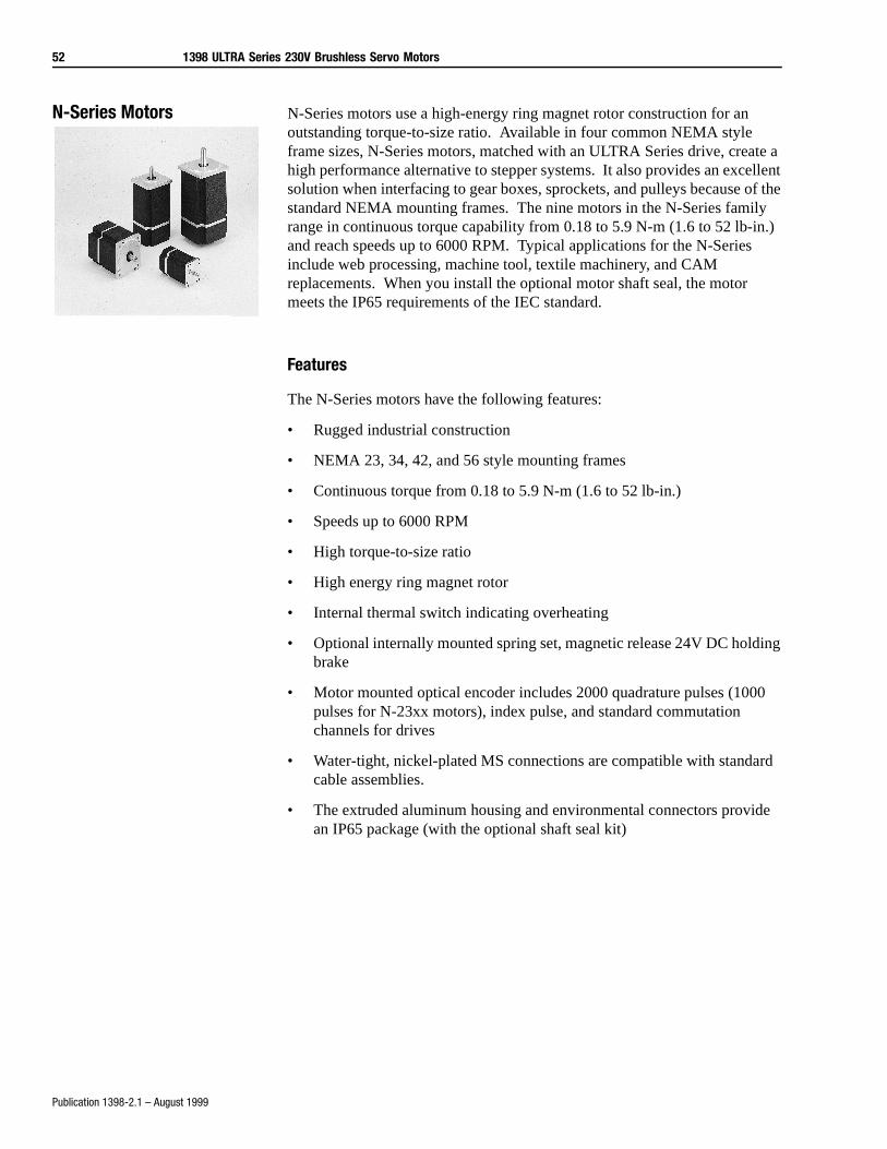
52 1398 ULTRA Series 230V Brushless Servo Motors
Publication 1398-2.1 – August 1999
N-Series Motors N-Series motors use a high-energy ring magnet rotor construction for an outstanding torque-to-size ratio. Available in four common NEMA style frame sizes, N-Series motors, matched with an ULTRA Series drive, create a high performance alternative to stepper systems. It also provides an excellent solution when interfacing to gear boxes, sprockets, and pulleys because of the standard NEMA mounting frames. The nine motors in the N-Series family range in continuous torque capability from 0.18 to 5.9 N-m (1.6 to 52 lb-in.) and reach speeds up to 6000 RPM. Typical applications for the N-Series include web processing, machine tool, textile machinery, and CAM replacements. When you install the optional motor shaft seal, the motor meets the IP65 requirements of the IEC standard.
Features
The N-Series motors have the following features:
• Rugged industrial construction
• NEMA 23, 34, 42, and 56 style mounting frames
• Continuous torque from 0.18 to 5.9 N-m (1.6 to 52 lb-in.)
• Speeds up to 6000 RPM
• High torque-to-size ratio
• High energy ring magnet rotor
• Internal thermal switch indicating overheating
• Optional internally mounted spring set, magnetic release 24V DC holding brake
• Motor mounted optical encoder includes 2000 quadrature pulses (1000 pulses for N-23xx motors), index pulse, and standard commutation channels for drives
• Water-tight, nickel-plated MS connections are compatible with standard cable assemblies.
• The extruded aluminum housing and environmental connectors provide an IP65 package (with the optional shaft seal kit)
1398 ULTRA Series 230V Brushless Servo Motors 53
Publication 1398-2.1 – August 1999
Typical Applications
Typical applications for the N-Series motors are:
• Machine tools
• Material handling
• Web processing
• Robotics
• Packaging machinery
Characteristics
• High performance stepper replacement
• NEMA mounting provides excellent mechanical interface
• Environmentally rugged
Selecting a Drive/Motor Combination
The following drive/motor combinations are available for the N-Series motors:
Motor ULTRA 100 ULTRA 200 ULTRA Plus
N-2302-1-F00AA 1398-DDM-005 1398-DDM-010 NA
N-2304-1-F00AA 1398-DDM-005 1398-DDM-010 NA
N-3406-2-H00AA 1398-DDM-009 1398-DDM-020 1398-PDM-20
N-3412-2-H00AA 1398-DDM-009 1398-DDM-020 1398-PDM-20
N-4214-2-H00AA 1398-DDM-009 1398-DDM-020 1398-PDM-20
N-4220-2-H00AA 1398-DDM-019 1398-DDM-030 1398-PDM-30
N-5630-2-H00AA 1398-DDM-019 1398-DDM-030 1398-PDM-30
N-5637-2-H00AA 1398-DDM-019 1398-DDM-030 1398-PDM-30
N-5647-2-H00AA 1398-DDM-019 1398-DDM-030 1398-PDM-30
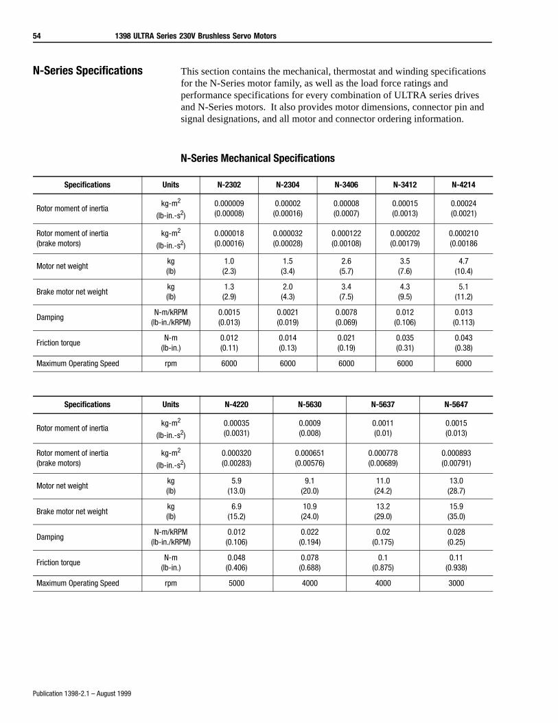
54 1398 ULTRA Series 230V Brushless Servo Motors
Publication 1398-2.1 – August 1999
N-Series Specifications This section contains the mechanical, thermostat and winding specifications for the N-Series motor family, as well as the load force ratings and performance specifications for every combination of ULTRA series drives and N-Series motors. It also provides motor dimensions, connector pin and signal designations, and all motor and connector ordering information.
N-Series Mechanical Specifications
Specifications Units N-2302 N-2304 N-3406 N-3412 N-4214
Rotor moment of inertiakg-m2
(lb-in.-s2)
0.000009(0.00008)
0.00002(0.00016)
0.00008(0.0007)
0.00015(0.0013)
0.00024(0.0021)
Rotor moment of inertia (brake motors)
kg-m2
(lb-in.-s2)
0.000018(0.00016)
0.000032(0.00028)
0.000122(0.00108)
0.000202(0.00179)
0.000210(0.00186
Motor net weightkg(lb)
1.0(2.3)
1.5(3.4)
2.6(5.7)
3.5(7.6)
4.7(10.4)
Brake motor net weightkg(lb)
1.3(2.9)
2.0(4.3)
3.4(7.5)
4.3(9.5)
5.1(11.2)
DampingN-m/kRPM
(lb-in./kRPM)0.0015(0.013)
0.0021(0.019)
0.0078(0.069)
0.012(0.106)
0.013(0.113)
Friction torqueN-m
(lb-in.)0.012(0.11)
0.014(0.13)
0.021(0.19)
0.035(0.31)
0.043(0.38)
Maximum Operating Speed rpm 6000 6000 6000 6000 6000
Specifications Units N-4220 N-5630 N-5637 N-5647
Rotor moment of inertiakg-m2
(lb-in.-s2)
0.00035(0.0031)
0.0009(0.008)
0.0011(0.01)
0.0015(0.013)
Rotor moment of inertia(brake motors)
kg-m2
(lb-in.-s2)
0.000320(0.00283)
0.000651(0.00576)
0.000778(0.00689)
0.000893(0.00791)
Motor net weightkg(lb)
5.9(13.0)
9.1(20.0)
11.0(24.2)
13.0(28.7)
Brake motor net weightkg(lb)
6.9(15.2)
10.9(24.0)
13.2(29.0)
15.9(35.0)
DampingN-m/kRPM
(lb-in./kRPM)0.012
(0.106)0.022
(0.194)0.02
(0.175)0.028(0.25)
Friction torqueN-m
(lb-in.)0.048
(0.406)0.078
(0.688)0.1
(0.875)0.11
(0.938)
Maximum Operating Speed rpm 5000 4000 4000 3000
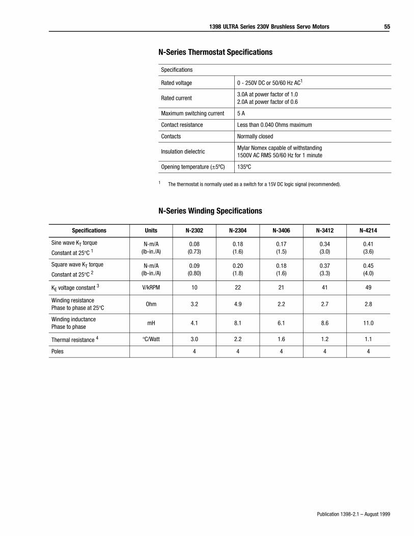
1398 ULTRA Series 230V Brushless Servo Motors 55
Publication 1398-2.1 – August 1999
N-Series Thermostat Specifications
1 The thermostat is normally used as a switch for a 15V DC logic signal (recommended).
N-Series Winding Specifications
Specifications
Rated voltage 0 - 250V DC or 50/60 Hz AC1
Rated current3.0A at power factor of 1.02.0A at power factor of 0.6
Maximum switching current 5 A
Contact resistance Less than 0.040 Ohms maximum
Contacts Normally closed
Insulation dielectricMylar Nomex capable of withstanding 1500V AC RMS 50/60 Hz for 1 minute
Opening temperature (±5ºC) 135ºC
Specifications Units N-2302 N-2304 N-3406 N-3412 N-4214
Sine wave KT torque
Constant at 25ºC 1N-m/A
(lb-in./A)0.08
(0.73)0.18(1.6)
0.17(1.5)
0.34(3.0)
0.41(3.6)
Square wave KT torque
Constant at 25ºC 2N-m/A
(lb-in./A)0.09
(0.80)0.20(1.8)
0.18(1.6)
0.37(3.3)
0.45(4.0)
KE voltage constant 3 V/kRPM 10 22 21 41 49
Winding resistance Phase to phase at 25ºC
Ohm 3.2 4.9 2.2 2.7 2.8
Winding inductance Phase to phase
mH 4.1 8.1 6.1 8.6 11.0
Thermal resistance 4 ºC/Watt 3.0 2.2 1.6 1.2 1.1
Poles 4 4 4 4 4
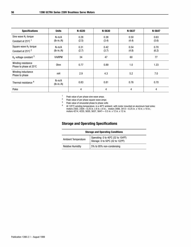
56 1398 ULTRA Series 230V Brushless Servo Motors
Publication 1398-2.1 – August 1999
1 Peak value of per phase sine wave amps.2 Peak value of per phase square wave amps3 Peak value of sinusoidal phase to phase volts4 At 125ºC winding temperature, in a 40ºC ambient, with motor mounted on aluminum heat sinks:
motors 2302, 2304—0.25 in. x 8 in. x 8 in.; motors 3406, 3412—0.25 in. x 10 in. x 10 in.; motors 4214, 4220, 5630, 5637, 5647— 0.5 in. x 12 in. x 12 in.
Storage and Operating Specifications
Specifications Units N-4220 N-5630 N-5637 N-5647
Sine wave KT torque
Constant at 25ºC 1N-m/A
(lb-in./A)0.28(2.5)
0.38(3.4)
0.50(4.4)
0.63(5.6)
Square wave KT torque
Constant at 25ºC 2N-m/A
(lb-in./A)0.31(2.7)
0.42(3.7)
0.54(4.8)
0.70(6.2)
KE voltage constant 3 V/kRPM 34 47 60 77
Winding resistance Phase to phase at 25ºC
Ohm 0.77 0.89 1.0 1.23
Winding inductance Phase to phase
mH 2.9 4.3 5.2 7.0
Thermal resistance 4N-m/A
(lb-in./A)0.83 0.81 0.76 0.70
Poles 4 4 4 4
Storage and Operating Conditions
Ambient TemperatureOperating: 0 to 40ºC (32 to 104ºF)Storage: 0 to 50ºC (32 to 122ºF)
Relative Humidity 5% to 95% non-condensing
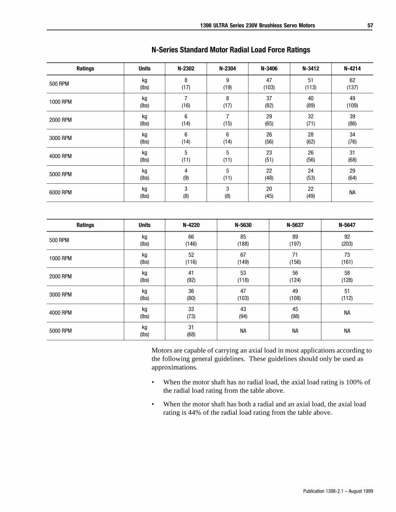
1398 ULTRA Series 230V Brushless Servo Motors 57
Publication 1398-2.1 – August 1999
N-Series Standard Motor Radial Load Force Ratings
Motors are capable of carrying an axial load in most applications according to the following general guidelines. These guidelines should only be used as approximations.
• When the motor shaft has no radial load, the axial load rating is 100% of the radial load rating from the table above.
• When the motor shaft has both a radial and an axial load, the axial load rating is 44% of the radial load rating from the table above.
Ratings Units N-2302 N-2304 N-3406 N-3412 N-4214
500 RPMkg
(lbs)8
(17)9
(19)47
(103)51
(113)62
(137)
1000 RPMkg
(lbs)7
(16)8
(17)37
(82)40
(89)49
(109)
2000 RPMkg
(lbs)6
(14)7
(15)29
(65)32
(71)39(86)
3000 RPMkg
(lbs)6
(14)6
(14)26
(56)28
(62)34(76)
4000 RPMkg
(lbs)5
(11)5
(11)23
(51)26
(56)31(68)
5000 RPMkg
(lbs)4
(9)5
(11)22
(48)24
(53)29(64)
6000 RPMkg
(lbs)3
(8)3
(8)20
(45)22
(49)NA
Ratings Units N-4220 N-5630 N-5637 N-5647
500 RPMkg
(lbs)66
(146)85
(188)89
(197)92
(203)
1000 RPMkg
(lbs)52
(116)67
(149)71
(156)73
(161)
2000 RPMkg
(lbs)41
(92)53
(118)56
(124)58
(128)
3000 RPMkg
(lbs)36
(80)47
(103)49
(108)51
(112)
4000 RPMkg
(lbs)33
(73)43
(94)45
(98)NA
5000 RPMkg
(lbs)31
(68)NA NA NA
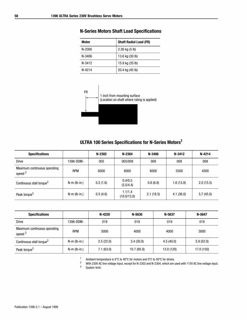
58 1398 ULTRA Series 230V Brushless Servo Motors
Publication 1398-2.1 – August 1999
N-Series Motors Shaft Load Specifications
ULTRA 100 Series Specifications for N-Series Motors1
1 Ambient temperature is 0ºC to 40ºC for motors and 0ºC to 50ºC for drives.2 With 230V AC line voltage input, except for N-2302 and N-2304, which are used with 115V AC line voltage input.3 System limit.
Motor Shaft Radial Load (FR)
N-2300 2.26 kg (5 lb)
N-3406 13.6 kg (30 lb)
N-3412 15.9 kg (35 lb)
N-4214 20.4 kg (45 lb)
FR1 inch from mounting surface(Location on shaft where rating is applied)
Specifications N-2302 N-2304 N-3406 N-3412 N-4214
Drive 1398-DDM- 005 005/009 009 009 009
Maximum continuous operating
speed 2 RPM 6000 6000 6000 5500 4500
Continuous stall torque2 N-m (lb-in.) 0.2 (1.6)0.4/0.5
(3.5/4.4)0.8 (6.8) 1.6 (13.8) 2.0 (15.5)
Peak torque3 N-m (lb-in.) 0.5 (4.6)1.1/1.4
(10.0/13.0)2.1 (18.5) 4.1 (36.0) 5.7 (45.0)
Specifications N-4220 N-5630 N-5637 N-5647
Drive 1398-DDM- 019 019 019 019
Maximum continuous operating
speed 2 RPM 5000 4000 4000 3000
Continuous stall torque2 N-m (lb-in.) 2.5 (22.0) 3.4 (30.0) 4.5 (40.0) 5.9 (52.0)
Peak torque3 N-m (lb-in.) 7.1 (63.0) 10.7 (95.0) 13.0 (120) 17.0 (150)
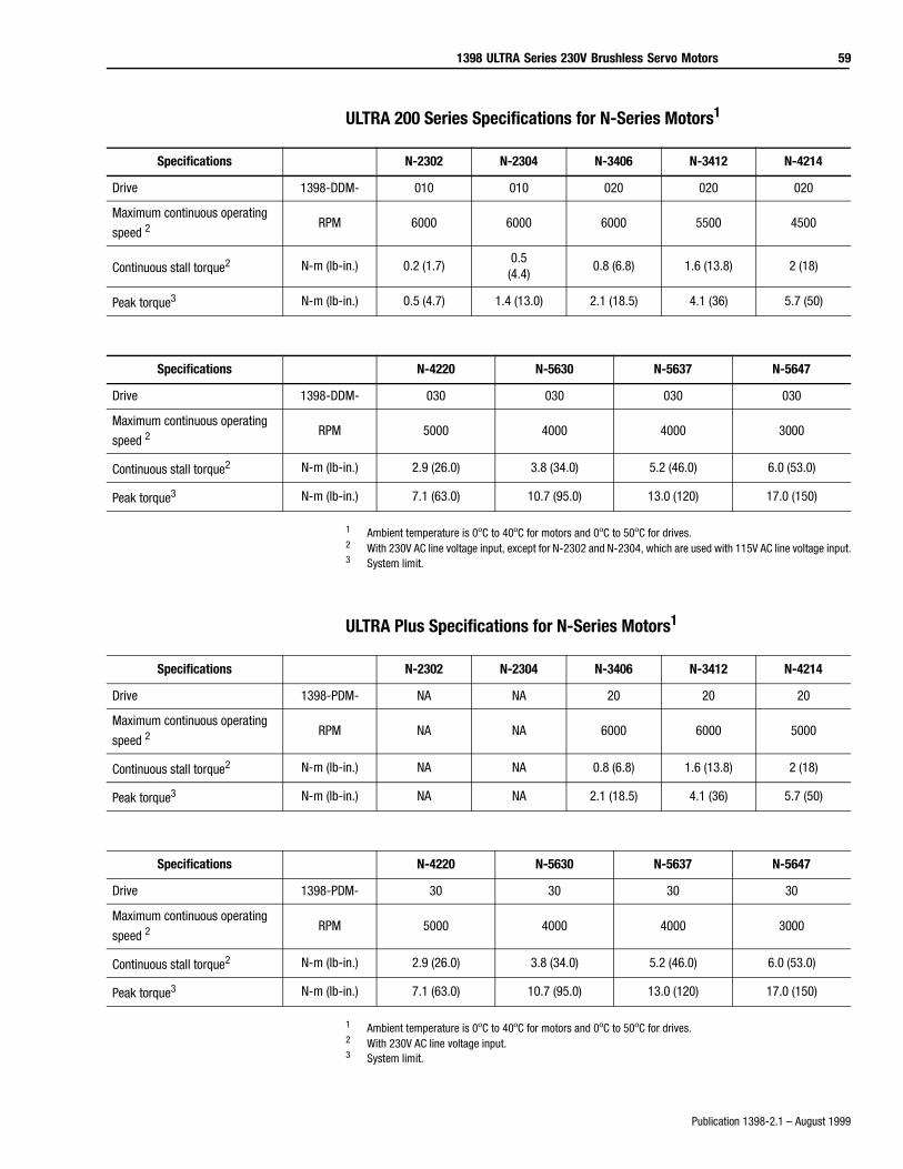
1398 ULTRA Series 230V Brushless Servo Motors 59
Publication 1398-2.1 – August 1999
ULTRA 200 Series Specifications for N-Series Motors1
1 Ambient temperature is 0ºC to 40ºC for motors and 0ºC to 50ºC for drives.2 With 230V AC line voltage input, except for N-2302 and N-2304, which are used with 115V AC line voltage input.3 System limit.
ULTRA Plus Specifications for N-Series Motors1
1 Ambient temperature is 0ºC to 40ºC for motors and 0ºC to 50ºC for drives.2 With 230V AC line voltage input.3 System limit.
Specifications N-2302 N-2304 N-3406 N-3412 N-4214
Drive 1398-DDM- 010 010 020 020 020
Maximum continuous operating
speed 2 RPM 6000 6000 6000 5500 4500
Continuous stall torque2 N-m (lb-in.) 0.2 (1.7)0.5
(4.4)0.8 (6.8) 1.6 (13.8) 2 (18)
Peak torque3 N-m (lb-in.) 0.5 (4.7) 1.4 (13.0) 2.1 (18.5) 4.1 (36) 5.7 (50)
Specifications N-4220 N-5630 N-5637 N-5647
Drive 1398-DDM- 030 030 030 030
Maximum continuous operating
speed 2RPM 5000 4000 4000 3000
Continuous stall torque2 N-m (lb-in.) 2.9 (26.0) 3.8 (34.0) 5.2 (46.0) 6.0 (53.0)
Peak torque3 N-m (lb-in.) 7.1 (63.0) 10.7 (95.0) 13.0 (120) 17.0 (150)
Specifications N-2302 N-2304 N-3406 N-3412 N-4214
Drive 1398-PDM- NA NA 20 20 20
Maximum continuous operating
speed 2 RPM NA NA 6000 6000 5000
Continuous stall torque2 N-m (lb-in.) NA NA 0.8 (6.8) 1.6 (13.8) 2 (18)
Peak torque3 N-m (lb-in.) NA NA 2.1 (18.5) 4.1 (36) 5.7 (50)
Specifications N-4220 N-5630 N-5637 N-5647
Drive 1398-PDM- 30 30 30 30
Maximum continuous operating
speed 2RPM 5000 4000 4000 3000
Continuous stall torque2 N-m (lb-in.) 2.9 (26.0) 3.8 (34.0) 5.2 (46.0) 6.0 (53.0)
Peak torque3 N-m (lb-in.) 7.1 (63.0) 10.7 (95.0) 13.0 (120) 17.0 (150)
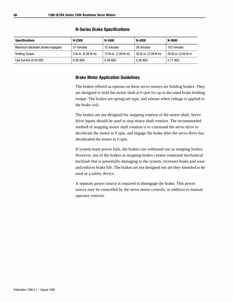
60 1398 ULTRA Series 230V Brushless Servo Motors
Publication 1398-2.1 – August 1999
N-Series Brake Specifications
Brake Motor Application Guidelines
The brakes offered as options on these servo motors are holding brakes. They
are designed to hold the motor shaft at 0 rpm for up to the rated brake holding
torque. The brakes are spring-set type, and release when voltage is applied to
the brake coil.
The brakes are not designed for stopping rotation of the motor shaft. Servo
drive inputs should be used to stop motor shaft rotation. The recommended
method of stopping motor shaft rotation is to command the servo drive to
decelerate the motor to 0 rpm, and engage the brake after the servo drive has
decelerated the motor to 0 rpm.
If system main power fails, the brakes can withstand use as stopping brakes.
However, use of the brakes as stopping brakes creates rotational mechanical
backlash that is potentially damaging to the system, increases brake pad wear
and reduces brake life. The brakes are not designed nor are they intended to be
used as a safety device.
A separate power source is required to disengage the brake. This power
source may be controlled by the servo motor controls, in addition to manual
operator controls.
Specifications N-2300 N-3400 N-4200 N-5600
Maximum Backlash (brake engaged) 31 minutes 72 minutes 36 minutes 102 minutes
Holding Torque 5 lb-in. (0.56 N-m) 15 lb-in. (1.69 N-m) 30 lb-in. (3.39 N-m) 50 lb-in. (5.64 N-m
Coil Current at 24 VDC 0.28 ADC 0.36 ADC 0.36 ADC 0.71 ADC

1398 ULTRA Series 230V Brushless Servo Motors 61
Publication 1398-2.1 – August 1999
N-2300 Motors Dimensions (see page 62 for dimension values)
N-3400, -4200, and -5600 Motors Dimensions(see page 62 for dimension values)
AB
L
BE
U
AH
BB
BJ is the diameter of the holeAJ is the diameter of the bolt circle
AKP
LB
LA
LC
AB
LBE
BB
AH
XDS
U
AK
P
BF is the diameter of the holes.AJ is the diameter of the bolt circle.LA
LD
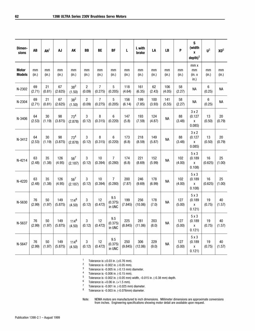
62 1398 ULTRA Series 230V Brushless Servo Motors
Publication 1398-2.1 – August 1999
1 Tolerance is ±0.03 in. (±0.76 mm). 2 Tolerance is -0.002 in. (-0.05 mm).3 Tolerance is -0.005 in. (-0.13 mm) diameter.4 Tolerance is -0.006 in. (-0.15 mm).5 Tolerance is -0.002 in. (-0.05 mm) width, -0.015 in. (-0.38 mm) depth.6 Tolerance is +0.06 in. (+1.5 mm). 7 Tolerance is -0.001 in. (-0.025 mm) diameter. 8 Tolerance is -0.003 in. (-0.076mm) diameter.
Note: NEMA motors are manufactured to inch dimensions. Millimeter dimensions are approximate conversions from inches. Engineering specifications showing motor detail are available upon request.
Dimen-sions
AB AH1 AJ AK BB BE BF LL with brake
LA LB P
S (width
x
depth)5U3 XD6
Motor Models
mm(in.)
mm(in.)
mm(in.)
mm(in.)
mm(in.)
mm(in.)
mm(in.)
mm(in.)
mm(in.)
mm(in.)
mm(in.)
mm(in.)
mm x mm(in. x in.)
mm(in.)
mm(in.)
N-230269
(2.71)21
(0.81)67
(2.625)382
(1.50)2
(0.09)7
(0.275)5
(0.205)118
(4.64)161
(6.35)62
(2.43)106
(4.05)58
(2.27)NA
6(0.25)
NA
N-230469
(2.71)21
(0.81)67
(2.625)382
(1.50)2
(0.09)7
(0.275)5
(0.205)156
(6.14)199
(7.85)100
(3.93)141
(5.55)58
(2.27)NA
6(0.25)
NA
N-340664
(2.53)30
(1.19)98
(3.875)734
(2.878)3
(0.12)8
(0.315)6
(0.220)147(5.8)
193(7.59)
124(4.87)
NA88
(3.48)
3 x 2(0.127
x 0.085)
13(0.50)
20(0.79)
N-341264
(2.53)30
(1.19)98
(3.875)734
(2.878)3
(0.12)8
(0.315)6
(0.220)173(6.8)
218(8.59)
149(5.87)
NA88
(3.48)
3 x 2(0.127
x 0.085)
13(0.50)
20(0.79)
N-421463
(2.48)35
(1.38)126
(4.95)567
(2.187)3
(0.12)10
(0.394)7
(0.280)174(6.8)
221(8.69)
152(5.99)
NA102
(4.00)
5 x 3(0.189
x 0.108)
16(0.625)
25(1.00)
N-422063
(2.48)35
(1.38)126
(4.95)567
(2.187)3
(0.12)10
(0.394)7
(0.280)200
(7.87)246
(9.69)178
(6.99)NA
102(4.00)
5 x 3(0.189
x 0.108)
16(0.625)
25(1.00)
N-563076
(2.99)50
(1.97)149
(5.875)1148
(4.50)3
(0.12)12
(0.472)
9.5 (0.375)in UNC
199(7.845)
256(10.06)
178(7.0)
NA127
(5.00)
5 x 3(0.189
x 0.121)
19(0.75)
40(1.57)
N-563776
(2.99)50
(1.97)149
(5.875)1148
(4.50)3
(0.12)12
(0.472)
9.5 (0.375)in UNC
225(8.845)
281(11.06)
203(8.0)
NA127
(5.00)
5 x 3(0.189
x 0.121)
19(0.75)
40(1.57)
N-564776
(2.99)50
(1.97)149
(5.875)1148
(4.50)3
(0.12)12
(0.472)
9.5 (0.375)in UNC
250(9.845)
306(12.06)
229(9.0)
NA127
(5.00)
5 x 3(0.189
x 0.121)
19(0.75)
40(1.57)
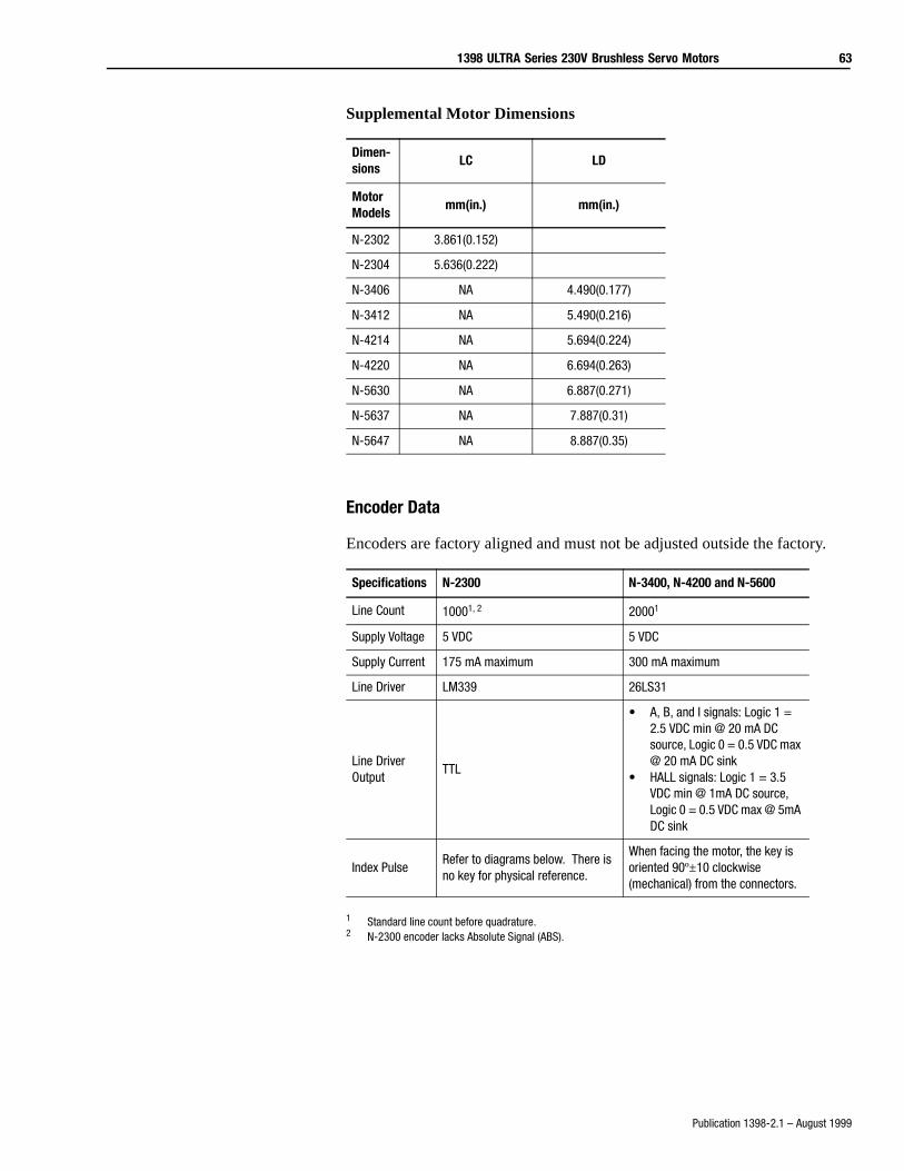
1398 ULTRA Series 230V Brushless Servo Motors 63
Publication 1398-2.1 – August 1999
Supplemental Motor Dimensions
Encoder Data
Encoders are factory aligned and must not be adjusted outside the factory.
1 Standard line count before quadrature.2 N-2300 encoder lacks Absolute Signal (ABS).
Dimen-sions
LC LD
Motor Models
mm(in.) mm(in.)
N-2302 3.861(0.152)
N-2304 5.636(0.222)
N-3406 NA 4.490(0.177)
N-3412 NA 5.490(0.216)
N-4214 NA 5.694(0.224)
N-4220 NA 6.694(0.263)
N-5630 NA 6.887(0.271)
N-5637 NA 7.887(0.31)
N-5647 NA 8.887(0.35)
Specifications N-2300 N-3400, N-4200 and N-5600
Line Count 10001, 2 20001
Supply Voltage 5 VDC 5 VDC
Supply Current 175 mA maximum 300 mA maximum
Line Driver LM339 26LS31
Line Driver Output
TTL
• A, B, and I signals: Logic 1 = 2.5 VDC min @ 20 mA DC source, Logic 0 = 0.5 VDC max @ 20 mA DC sink
• HALL signals: Logic 1 = 3.5 VDC min @ 1mA DC source, Logic 0 = 0.5 VDC max @ 5mA DC sink
Index PulseRefer to diagrams below. There is no key for physical reference.
When facing the motor, the key is oriented 90º±10 clockwise (mechanical) from the connectors.
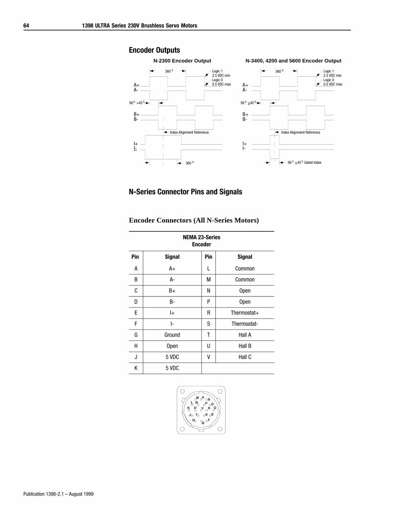
64 1398 ULTRA Series 230V Brushless Servo Motors
Publication 1398-2.1 – August 1999
Encoder Outputs
N-Series Connector Pins and Signals
Encoder Connectors (All N-Series Motors)
NEMA 23-SeriesEncoder
Pin Signal Pin Signal
A A+ L Common
B A- M Common
C B+ N Open
D B- P Open
E I+ R Thermostat+
F I- S Thermostat-
G Ground T Hall A
H Open U Hall B
J 5 VDC V Hall C
K 5 VDC
A+A-
B+B-
I+I-
Logic 1
Logic 0
90 o +45 o
Index Alignment Reference
360 o
2.5 VDC min
0.5 VDC max A+A-
B+B-
I+I-
360 o Logic 1
Logic 0
90 o +45 o
Index Alignment Reference
90 o +45 o Gated Index
2.5 VDC min
0.5 VDC max
N-2300 Encoder Output N-3400, 4200 and 5600 Encoder Output
360 o
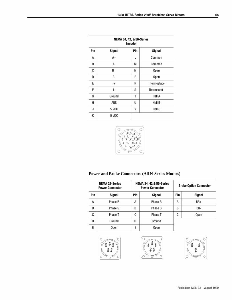
1398 ULTRA Series 230V Brushless Servo Motors 65
Publication 1398-2.1 – August 1999
Power and Brake Connectors (All N-Series Motors)
NEMA 34, 42, & 56-SeriesEncoder
Pin Signal Pin Signal
A A+ L Common
B A- M Common
C B+ N Open
D B- P Open
E I+ R Thermostat+
F I- S Thermostat-
G Ground T Hall A
H ABS U Hall B
J 5 VDC V Hall C
K 5 VDC
NEMA 23-SeriesPower Connector
NEMA 34, 42 & 56-SeriesPower Connector
Brake Option Connector
Pin Signal Pin Signal Pin Signal
A Phase R A Phase R A BR+
B Phase S B Phase S B BR-
C Phase T C Phase T C Open
D Ground D Ground
E Open E Open
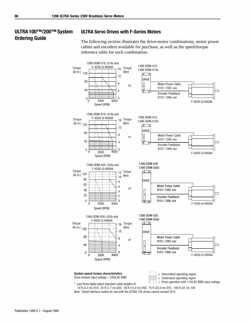
66 1398 ULTRA Series 230V Brushless Servo Motors
Publication 1398-2.1 – August 1999
ULTRA 100™/200™ System Ordering Guide
ULTRA Servo Drives with F-Series Motors
The following section illustrates the drive-motor combinations, motor power cables and encoders available for purchase, as well as the speed/torque reference table for each combination.
Torque(lb-in.) 120
80
40
0
1398-DDM-019,-019x andF-4030-Q-H00AA
0 2000 4000Speed (RPM)
Torque(Nm)
16
12
8
4
0
=DRIVE
1398-DDM-0191398-DDM-019x
Motor Power Cable9101-1382-xxx
Encoder Feedback9101-1366-xxx
F-4030-Q-H00AA
Torque(lb-in.) 120
80
40
0
1398-DDM-019,-019x andF-4050-Q-H00AA
0 2000 4000Speed (RPM)
Torque(Nm)
16
12
8
4
0
=DRIVE
1398-DDM-0191398-DDM-019x
Motor Power Cable9101-1382-xxx
Encoder Feedback9101-1366-xxx
F-4050-Q-H00AA
=
Torque(lb-in.)
0
20
40
60
80
100
1398-DDM-020,-020x andF-4030-Q-H00AA
0 2000 4000
Speed (RPM)
Torque(Nm)
0
24
6
81012
1398-DDM-0201398-DDM-020x
Motor Power Cable9101-1382-xxx
Encoder Feedback9101-1366-xxx
DRIVE
F-4030-Q-H00AA
=
16
12
8
4
00 2000 4000
120
80
40
0
Torque(lb-in.)
Speed (RPM)
1398-DDM-030,-030x andF-4050-Q-H00AA
Torque(Nm)
1398-DDM-0301398-DDM-030x
Motor Power Cable9101-1382-xxx
Encoder Feedback9101-1366-xxx
DRIVE
F-4050-Q-H00AA
= Intermittent operating region= Continuous operating region= Drive operation with 115V AC RMS input voltage
System speed-torque characteristicsDrive module input voltage = 230V AC RMS
* Last three digits select standard cable lengths of: 10 ft (3.0 m)-010; 25 ft (7.7 m)-025; 50 ft (15.0 m)-050; 75 ft (23.0 m)-075; 100 ft (31 m)-100Note: Serial interface cables for use with the ULTRA 100 drives cannot exceed 50 ft.
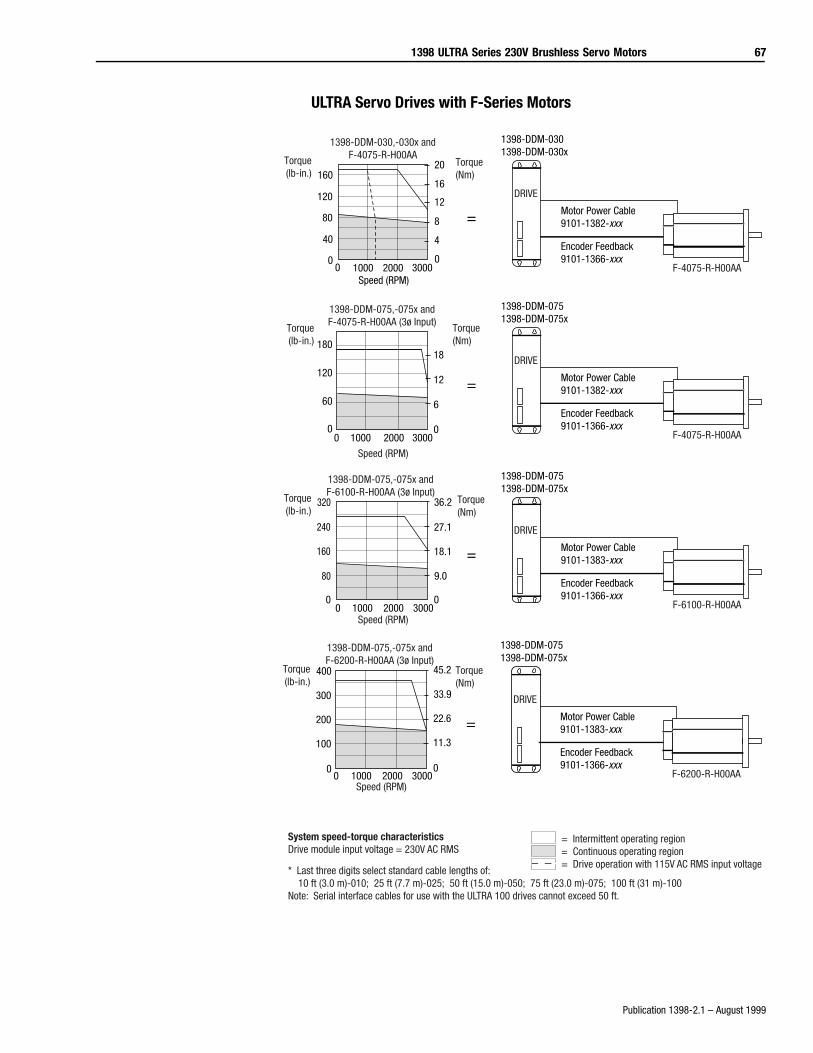
1398 ULTRA Series 230V Brushless Servo Motors 67
Publication 1398-2.1 – August 1999
ULTRA Servo Drives with F-Series Motors
20
16
12
8
4
0
Speed (RPM)0 1000 2000 3000
160
120
80
40
0
Torque(lb-in.)
Torque(Nm)
1398-DDM-030,-030x andF-4075-R-H00AA
=
1398-DDM-0301398-DDM-030x
Motor Power Cable9101-1382-xxx
Encoder Feedback9101-1366-xxx
DRIVE
F-4075-R-H00AA
18
12
6
00 1000 2000 3000
180
120
60
0
Torque(lb-in.)
Torque(Nm)
Speed (RPM)
1398-DDM-075,-075x andF-4075-R-H00AA (3ø Input)
=
1398-DDM-0751398-DDM-075x
Motor Power Cable9101-1382-xxx
Encoder Feedback9101-1366-xxx
DRIVE
F-4075-R-H00AA
36.2
27.1
18.1
9.0
00 1000 2000 3000
320
240
160
80
0
Torque(lb-in.)
Torque(Nm)
Speed (RPM)
1398-DDM-075,-075x andF-6100-R-H00AA (3ø Input)
=
1398-DDM-0751398-DDM-075x
Motor Power Cable9101-1383-xxx
Encoder Feedback9101-1366-xxx
DRIVE
F-6100-R-H00AA
0
45.2
33.9
22.6
11.3
00 1000 2000 3000
400
300
200
100
Torque(lb-in.)
Torque(Nm)
Speed (RPM)
1398-DDM-075,-075x andF-6200-R-H00AA (3ø Input)
=
1398-DDM-0751398-DDM-075x
Motor Power Cable9101-1383-xxx
Encoder Feedback9101-1366-xxx
DRIVE
F-6200-R-H00AA
= Intermittent operating region= Continuous operating region= Drive operation with 115V AC RMS input voltage
System speed-torque characteristicsDrive module input voltage = 230V AC RMS
* Last three digits select standard cable lengths of: 10 ft (3.0 m)-010; 25 ft (7.7 m)-025; 50 ft (15.0 m)-050; 75 ft (23.0 m)-075; 100 ft (31 m)-100Note: Serial interface cables for use with the ULTRA 100 drives cannot exceed 50 ft.
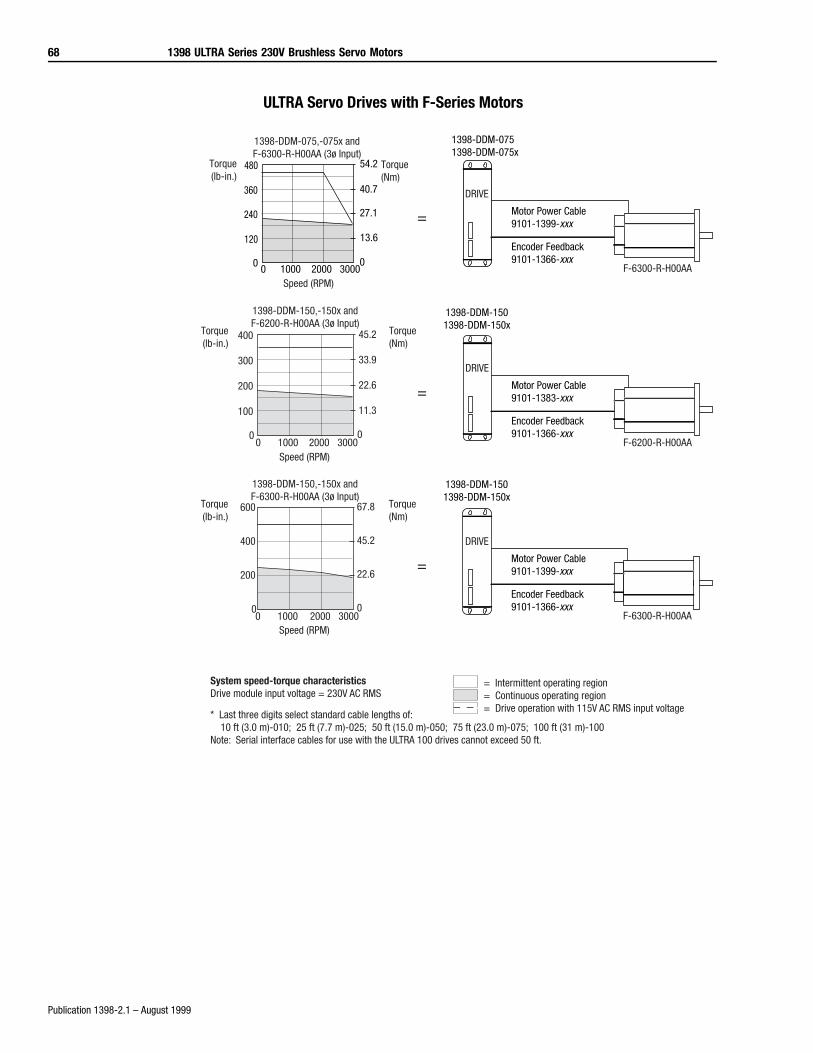
68 1398 ULTRA Series 230V Brushless Servo Motors
Publication 1398-2.1 – August 1999
ULTRA Servo Drives with F-Series Motors
54.2
40.7
27.1
13.6
00 1000 2000 3000
480
360
240
120
0
Torque(lb-in.)
Torque(Nm)
Speed (RPM)
1398-DDM-075,-075x andF-6300-R-H00AA (3ø Input)
= Intermittent operating region= Continuous operating region= Drive operation with 115V AC RMS input voltage
System speed-torque characteristicsDrive module input voltage = 230V AC RMS
* Last three digits select standard cable lengths of: 10 ft (3.0 m)-010; 25 ft (7.7 m)-025; 50 ft (15.0 m)-050; 75 ft (23.0 m)-075; 100 ft (31 m)-100Note: Serial interface cables for use with the ULTRA 100 drives cannot exceed 50 ft.
45.2
33.9
22.6
11.3
00 1000 2000 3000
400
300
200
100
0
1398-DDM-150,-150x andF-6200-R-H00AA (3ø Input)
Speed (RPM)
Torque(lb-in.)
Torque(Nm)
=
1398-DDM-1501398-DDM-150x
Motor Power Cable9101-1383-xxx
Encoder Feedback9101-1366-xxx
DRIVE
F-6200-R-H00AA
1398-DDM-0751398-DDM-075x
Motor Power Cable9101-1399-xxx
Encoder Feedback9101-1366-xxx
DRIVE
F-6300-R-H00AA
=
67.8
45.2
22.6
00 1000 2000 3000
600
400
200
0
1398-DDM-150,-150x andF-6300-R-H00AA (3ø Input)
Speed (RPM)
Torque(lb-in.)
Torque(Nm)
=
1398-DDM-1501398-DDM-150x
Motor Power Cable9101-1399-xxx
Encoder Feedback9101-1366-xxx
DRIVE
F-6300-R-H00AA
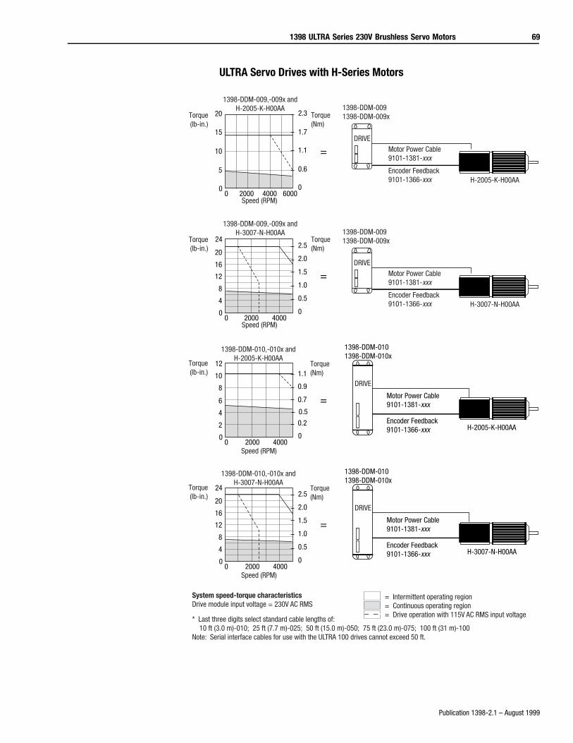
1398 ULTRA Series 230V Brushless Servo Motors 69
Publication 1398-2.1 – August 1999
ULTRA Servo Drives with H-Series Motors
0 2000 4000
2.5
2.0
1.5
1.0
0.5
0
24
20
16
12
8
4
0
Torque(lb-in.)
Torque(Nm)
Speed (RPM)
1398-DDM-009,-009x andH-3007-N-H00AA
=DRIVE
1398-DDM-0091398-DDM-009x
Motor Power Cable9101-1381-xxx
Encoder Feedback9101-1366-xxx H-3007-N-H00AA
0 2000 4000
2.5
2.0
1.5
1.0
0.5
0
24
20
16
12
8
4
0
Torque(lb-in.)
Torque(Nm)
Speed (RPM)
1398-DDM-010,-010x andH-3007-N-H00AA
=
1398-DDM-0101398-DDM-010x
Motor Power Cable9101-1381-xxx
Encoder Feedback9101-1366-xxx H-3007-N-H00AA
DRIVE
= Intermittent operating region= Continuous operating region= Drive operation with 115V AC RMS input voltage
System speed-torque characteristicsDrive module input voltage = 230V AC RMS
* Last three digits select standard cable lengths of: 10 ft (3.0 m)-010; 25 ft (7.7 m)-025; 50 ft (15.0 m)-050; 75 ft (23.0 m)-075; 100 ft (31 m)-100Note: Serial interface cables for use with the ULTRA 100 drives cannot exceed 50 ft.
0 2000 4000
2.3
1.7
1.1
0.6
0
20
15
10
5
0
Torque(lb-in.)
Torque(Nm)
Speed (RPM)
1398-DDM-009,-009x andH-2005-K-H00AA
=DRIVE
1398-DDM-0091398-DDM-009x
Motor Power Cable9101-1381-xxx
Encoder Feedback9101-1366-xxx H-2005-K-H00AA
0 2000 4000
1.1
0.9
0.7
0.5
0.2
0
12
10
8
6
4
2
0
Torque(lb-in.)
Torque(Nm)
Speed (RPM)
1398-DDM-010,-010x andH-2005-K-H00AA
=
1398-DDM-0101398-DDM-010x
Motor Power Cable9101-1381-xxx
Encoder Feedback9101-1366-xxx H-2005-K-H00AA
DRIVE
6000
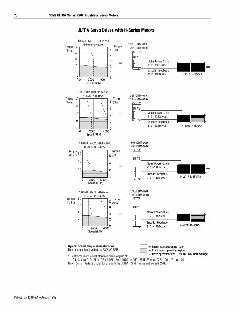
70 1398 ULTRA Series 230V Brushless Servo Motors
Publication 1398-2.1 – August 1999
ULTRA Servo Drives with H-Series Motors
=
1398-DDM-0201398-DDM-020x
Motor Power Cable9101-1381-xxx
Encoder Feedback9101-1366-xxx H-3016-N-H00AA
DRIVE
0 2000 4000
6
4
2
0
60
40
20
0
1398-DDM-020,-020x andH-3016-N-H00AA
Torque(lb-in.)
Torque(Nm)
Speed (RPM)
8
6
4
2
00 2000 4000
80
60
40
20
0
Torque(Nm)
Torque(lb-in.)
Speed (RPM)
1398-DDM-020,-020x andH-4030-P-H00AA
=
1398-DDM-0201398-DDM-020x
Motor Power Cable9101-1382-xxx
Encoder Feedback9101-1366-xxx H-4030-P-H00AA
DRIVE
= Intermittent operating region= Continuous operating region= Drive operation with 115V AC RMS input voltage
= Intermittent operating region= Continuous operating region= Drive operation with 115V AC RMS input voltage
System speed-torque characteristicsDrive module input voltage = 230V AC RMS
* Last three digits select standard cable lengths of: 10 ft (3.0 m)-010; 25 ft (7.7 m)-025; 50 ft (15.0 m)-050; 75 ft (23.0 m)-075; 100 ft (31 m)-100Note: Serial interface cables for use with the ULTRA 100 drives cannot exceed 50 ft.
5
4
3
2
1
0
50
40
30
20
10
00 2000 4000
Torque(lb-in.)
Torque(Nm)
Speed (RPM)
1398-DDM-019,-019x andH-3016-N-H00AA
=DRIVE
1398-DDM-0191398-DDM-019x
Motor Power Cable9101-1381-xxx
Encoder Feedback9101-1366-xxx H-3016-N-H00AA
8
6
4
2
00 2000 4000
80
60
40
20
0
Torque(lb-in.)
Torque(Nm)
Speed (RPM)
1398-DDM-019,-019x andH-4030-P-H00AA
=DRIVE
1398-DDM-0191398-DDM-019x
Motor Power Cable9101-1382-xxx
Encoder Feedback9101-1366-xxx H-4030-P-H00AA
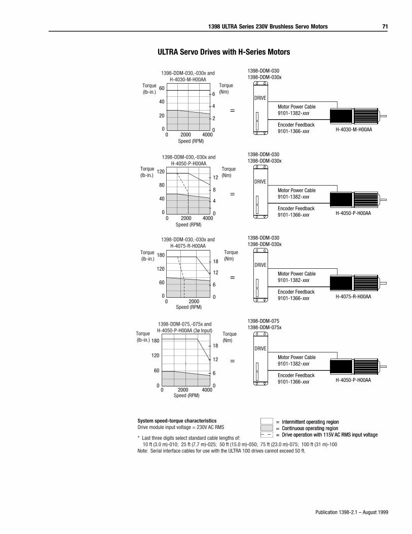
1398 ULTRA Series 230V Brushless Servo Motors 71
Publication 1398-2.1 – August 1999
ULTRA Servo Drives with H-Series Motors
18
12
6
00 2000
180
120
60
0
Torque(lb-in.)
Speed (RPM)
Torque(Nm)
1398-DDM-030,-030x andH-4075-R-H00AA
=
1398-DDM-0301398-DDM-030x
Motor Power Cable9101-1382-xxx
Encoder Feedback9101-1366-xxx H-4075-R-H00AA
DRIVE
18
12
6
0
180
120
60
00 2000 4000
Torque(lb-in.)
Torque(Nm)
Speed (RPM)
1398-DDM-075,-075x andH-4050-P-H00AA (3ø Input)
=
1398-DDM-0751398-DDM-075x
Motor Power Cable9101-1382-xxx
Encoder Feedback9101-1366-xxx H-4050-P-H00AA
DRIVE
= Intermittent operating region= Continuous operating region= Drive operation with 115V AC RMS input voltage
= Intermittent operating region= Continuous operating region= Drive operation with 115V AC RMS input voltage
System speed-torque characteristicsDrive module input voltage = 230V AC RMS
* Last three digits select standard cable lengths of: 10 ft (3.0 m)-010; 25 ft (7.7 m)-025; 50 ft (15.0 m)-050; 75 ft (23.0 m)-075; 100 ft (31 m)-100Note: Serial interface cables for use with the ULTRA 100 drives cannot exceed 50 ft.
0 2000 4000
6
4
2
0
60
40
20
0
Torque(Nm)
Torque(lb-in.)
1398-DDM-030,-030x andH-4030-M-H00AA
Speed (RPM)
=
1398-DDM-0301398-DDM-030x
Motor Power Cable9101-1382-xxx
Encoder Feedback9101-1366-xxx H-4030-M-H00AA
DRIVE
12
8
4
0
120
80
40
00 2000 4000
Torque(Nm)
Torque(lb-in.)
Speed (RPM)
1398-DDM-030,-030x andH-4050-P-H00AA
=
1398-DDM-0301398-DDM-030x
Motor Power Cable9101-1382-xxx
Encoder Feedback9101-1366-xxx H-4050-P-H00AA
DRIVE
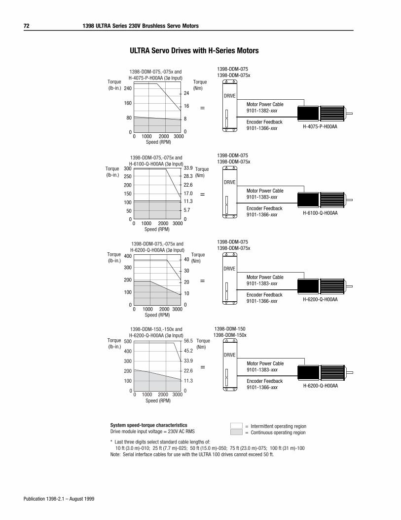
72 1398 ULTRA Series 230V Brushless Servo Motors
Publication 1398-2.1 – August 1999
ULTRA Servo Drives with H-Series Motors
=
1398-DDM-0751398-DDM-075x
Motor Power Cable9101-1383-xxx
Encoder Feedback9101-1366-xxx H-6200-Q-H00AA
DRIVE
40
30
20
10
0
400
300
200
100
00 1000 2000 3000
Torque(lb-in.)
Torque(Nm)
Speed (RPM)
1398-DDM-075,-075x andH-6200-Q-H00AA (3ø Input)
1398-DDM-1501398-DDM-150x
Motor Power Cable9101-1383-xxx
Encoder Feedback9101-1366-xxx H-6200-Q-H00AA
DRIVE
Torque(lb-in.)
Torque(Nm)
Speed (RPM)
1398-DDM-150,-150x andH-6200-Q-H00AA (3ø Input)
=
56.5
45.2
33.9
22.6
11.3
00 1000 2000 3000
500
400
300
200
100
0
= Intermittent operating region= Continuous operating region
System speed-torque characteristicsDrive module input voltage = 230V AC RMS
* Last three digits select standard cable lengths of: 10 ft (3.0 m)-010; 25 ft (7.7 m)-025; 50 ft (15.0 m)-050; 75 ft (23.0 m)-075; 100 ft (31 m)-100Note: Serial interface cables for use with the ULTRA 100 drives cannot exceed 50 ft.
=
1398-DDM-0751398-DDM-075x
Motor Power Cable9101-1382-xxx
Encoder Feedback9101-1366-xxx H-4075-P-H00AA
DRIVE24
16
8
00 1000 2000 3000
240
160
80
0
Torque(lb-in.)
Torque(Nm)
Speed (RPM)
1398-DDM-075,-075x andH-4075-P-H00AA (3ø Input)
=
1398-DDM-0751398-DDM-075x
Motor Power Cable9101-1383-xxx
Encoder Feedback9101-1366-xxx H-6100-Q-H00AA
DRIVE28.3
22.6
17.0
11.3
5.7
00 1000 2000 3000
300
200
100
0
Torque(lb-in.)
Torque(Nm)
Speed (RPM)
1398-DDM-075,-075x andH-6100-Q-H00AA (3ø Input)
33.9
250
150
50
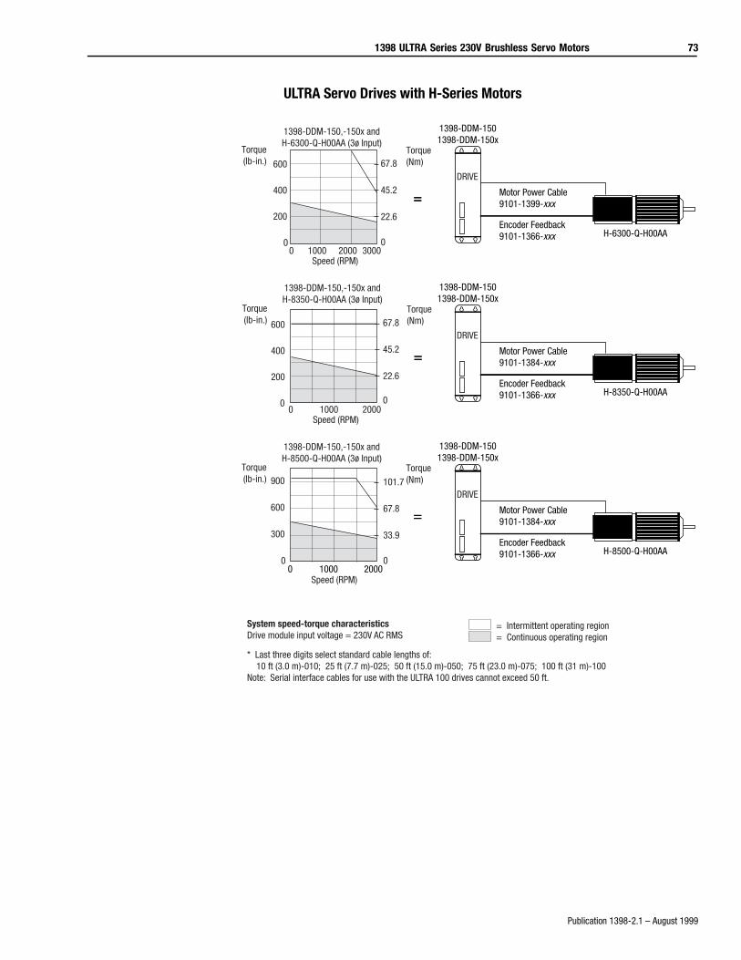
1398 ULTRA Series 230V Brushless Servo Motors 73
Publication 1398-2.1 – August 1999
ULTRA Servo Drives with H-Series Motors
= Motor Power Cable9101-1384-xxx
Encoder Feedback9101-1366-xxx H-8350-Q-H00AA
DRIVE
1398-DDM-1501398-DDM-150x
67.8
45.2
22.6
00 1000 2000
600
400
200
0
Torque(lb-in.)
Torque(Nm)
Speed (RPM)
1398-DDM-150,-150x andH-8350-Q-H00AA (3ø Input)
=
= Motor Power Cable9101-1384-xxx
Encoder Feedback9101-1366-xxx H-8500-Q-H00AA
DRIVE
0 1000 2000Speed (RPM)
1398-DDM-1501398-DDM-150x
101.7
67.8
33.9
0
900
600
300
0
Torque(lb-in.)
Torque(Nm)
1398-DDM-150,-150x andH-8500-Q-H00AA (3ø Input)
=
= Intermittent operating region= Continuous operating region
System speed-torque characteristicsDrive module input voltage = 230V AC RMS
* Last three digits select standard cable lengths of: 10 ft (3.0 m)-010; 25 ft (7.7 m)-025; 50 ft (15.0 m)-050; 75 ft (23.0 m)-075; 100 ft (31 m)-100Note: Serial interface cables for use with the ULTRA 100 drives cannot exceed 50 ft.
= Motor Power Cable9101-1399-xxx
Encoder Feedback9101-1366-xxx H-6300-Q-H00AA
DRIVE67.8
45.2
22.6
0
600
400
200
00 1000 2000 3000
Torque(lb-in.)
Torque(Nm)
Speed (RPM)
1398-DDM-150,-150x andH-6300-Q-H00AA (3ø Input)
=
1398-DDM-1501398-DDM-150x
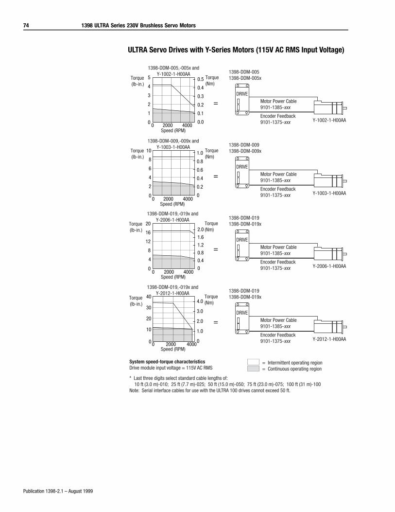
74 1398 ULTRA Series 230V Brushless Servo Motors
Publication 1398-2.1 – August 1999
ULTRA Servo Drives with Y-Series Motors (115V AC RMS Input Voltage)
0.5
0.4
0.3
0.2
0.1
0.0
5
4
3
2
1
00 2000 4000
Torque(lb-in.)
1398-DDM-005,-005x andY-1002-1-H00AA
Speed (RPM)
Torque(Nm)
=DRIVE
1398-DDM-0051398-DDM-005x
Motor Power Cable9101-1385-xxx
Encoder Feedback9101-1375-xxx Y-1002-1-H00AA
=DRIVE
1398-DDM-0091398-DDM-009x
Motor Power Cable9101-1385-xxx
Encoder Feedback9101-1375-xxx Y-1003-1-H00AA
1.0
0.8
0.6
0.4
0.2
0
10
8
6
4
2
00 2000 4000
Torque(lb-in.)
1398-DDM-009,-009x andY-1003-1-H00AA
Speed (RPM)
Torque(Nm)
=DRIVE
1398-DDM-0191398-DDM-019x
Motor Power Cable9101-1385-xxx
Encoder Feedback9101-1375-xxx Y-2006-1-H00AA
2.0
1.6
1.2
0.8
0.4
0
20
16
12
8
4
00 2000 4000
Torque(lb-in.)
1398-DDM-019,-019x andY-2006-1-H00AA
Speed (RPM)
Torque(Nm)
=DRIVE
1398-DDM-0191398-DDM-019x
Motor Power Cable9101-1385-xxx
Encoder Feedback9101-1375-xxx Y-2012-1-H00AA
4.0
3.0
2.0
1.0
0
40
30
20
10
0 0 2000 4000
Torque(lb-in.)
1398-DDM-019,-019x andY-2012-1-H00AA
Speed (RPM)
Torque(Nm)
= Intermittent operating region= Continuous operating region
System speed-torque characteristicsDrive module input voltage = 115V AC RMS
* Last three digits select standard cable lengths of: 10 ft (3.0 m)-010; 25 ft (7.7 m)-025; 50 ft (15.0 m)-050; 75 ft (23.0 m)-075; 100 ft (31 m)-100Note: Serial interface cables for use with the ULTRA 100 drives cannot exceed 50 ft.
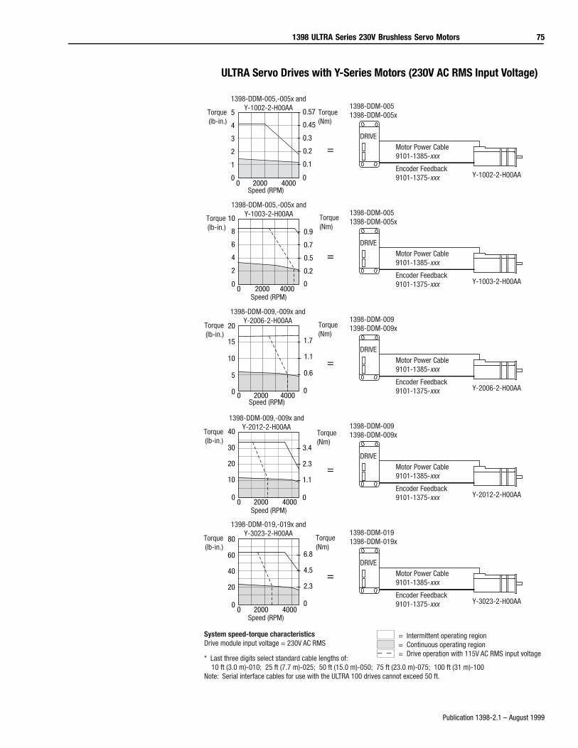
1398 ULTRA Series 230V Brushless Servo Motors 75
Publication 1398-2.1 – August 1999
ULTRA Servo Drives with Y-Series Motors (230V AC RMS Input Voltage)
0.57
0.45
0.3
0.2
0.1
0
5
4
3
2
1
00 2000 4000
Torque(lb-in.)
1398-DDM-005,-005x andY-1002-2-H00AA
Speed (RPM)
Torque(Nm)
=DRIVE
1398-DDM-0051398-DDM-005x
Motor Power Cable9101-1385-xxx
Encoder Feedback9101-1375-xxx Y-1002-2-H00AA
=DRIVE
1398-DDM-0051398-DDM-005x
Motor Power Cable9101-1385-xxx
Encoder Feedback9101-1375-xxx Y-1003-2-H00AA
0.9
0.7
0.5
0.2
0
10
8
6
4
2
00 2000 4000
Torque(lb-in.)
1398-DDM-005,-005x andY-1003-2-H00AA
Speed (RPM)
Torque(Nm)
=DRIVE
1398-DDM-0091398-DDM-009x
Motor Power Cable9101-1385-xxx
Encoder Feedback9101-1375-xxx Y-2006-2-H00AA
20
15
10
5
0 0 2000 4000
1.7
1.1
0.6
0
Torque(lb-in.)
1398-DDM-009,-009x andY-2006-2-H00AA
Speed (RPM)
Torque(Nm)
=DRIVE
1398-DDM-0091398-DDM-009x
Motor Power Cable9101-1385-xxx
Encoder Feedback9101-1375-xxx Y-2012-2-H00AA
40
30
20
10
00 2000 4000
3.4
2.3
1.1
0
Torque(lb-in.)
1398-DDM-009,-009x andY-2012-2-H00AA
Speed (RPM)
Torque(Nm)
=DRIVE
1398-DDM-0191398-DDM-019x
Motor Power Cable9101-1385-xxx
Encoder Feedback9101-1375-xxx Y-3023-2-H00AA
80
60
40
20
00 2000 4000
6.8
4.5
2.3
0
Torque(lb-in.)
1398-DDM-019,-019x andY-3023-2-H00AA
Speed (RPM)
Torque(Nm)
= Intermittent operating region= Continuous operating region= Drive operation with 115V AC RMS input voltage
System speed-torque characteristicsDrive module input voltage = 230V AC RMS
* Last three digits select standard cable lengths of: 10 ft (3.0 m)-010; 25 ft (7.7 m)-025; 50 ft (15.0 m)-050; 75 ft (23.0 m)-075; 100 ft (31 m)-100Note: Serial interface cables for use with the ULTRA 100 drives cannot exceed 50 ft.
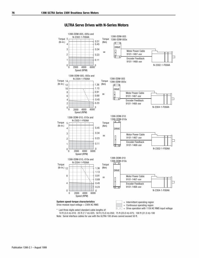
76 1398 ULTRA Series 230V Brushless Servo Motors
Publication 1398-2.1 – August 1999
ULTRA Servo Drives with N-Series Motors
=DRIVE
1398-DDM-0051398-DDM-005x
Motor Power Cable9101-1467-xxx
Encoder Feedback9101-1468-xxx
N-2302-1-F00AA
Torque(lb-in.)
1398-DDM-005,-005x andN-2302-1-F00AA
Speed (RPM)
Torque(Nm)
0
1
2
3
4
5
20000 4000 60000
0.11
0.23
0.34
0.450.51
=DRIVE
1398-DDM-0051398-DDM-005x
Motor Power Cable9101-1467-xxx
Encoder Feedback9101-1468-xxx
N-2304-1-F00AA
1.361.130.910.69
0.450.23
0
14
121086
42
00 2000 4000 6000
Torque(lb-in.)
1398-DDM-005,-005x andN-2304-1-F00AA
Speed (RPM)
Torque(Nm)
=
1398-DDM-0101398-DDM-010x
Motor Power Cable9101-1467-xxx
Encoder Feedback9101-1468-xxx
N-2302-1-F00AA
DRIVE
5
4
3
2
1
00 2000 4000 6000
0.45
0.34
0.23
0.11
0
1398-DDM-010,-010x andN-2302-1-F00AA
Torque(Nm)
Torque(lb-in.)
Speed (RPM)
=
1398-DDM-0101398-DDM-010x
Motor Power Cable9101-1467-xxx
Encoder Feedback9101-1468-xxx
N-2304-1-F00AA
DRIVE
1398-DDM-010,-010x andN-2304-1-F00AA
Torque(Nm)
Torque(lb-in.)
Speed (RPM)
1.36
1.13
0.91
0.69
0.45
0.23
0
12
8
4
00 2000 4000 6000
= Intermittent operating region= Continuous operating region= Drive operation with 115V AC RMS input voltage
System speed-torque characteristicsDrive module input voltage = 230V AC RMS
* Last three digits select standard cable lengths of: 10 ft (3.0 m)-010; 25 ft (7.7 m)-025; 50 ft (15.0 m)-050; 75 ft (23.0 m)-075; 100 ft (31.0 m)-100Note: Serial interface cables for use with the ULTRA 100 drives cannot exceed 50 ft.
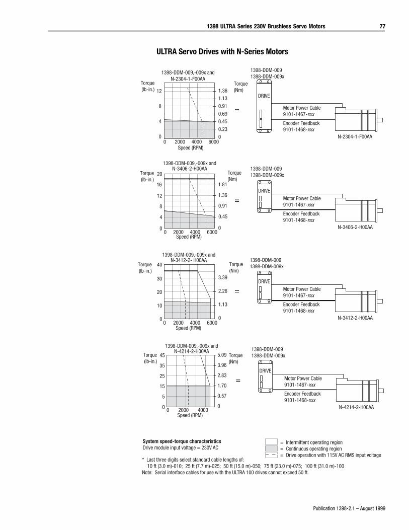
1398 ULTRA Series 230V Brushless Servo Motors 77
Publication 1398-2.1 – August 1999
ULTRA Servo Drives with N-Series Motors
=DRIVE
1398-DDM-0091398-DDM-009x
Motor Power Cable9101-1467-xxx
Encoder Feedback9101-1468-xxx
N-3406-2-H00AA
1.81
1.36
0.91
0.45
0
20
16
12
8
4
00 2000 4000 6000
Torque(lb-in.)
1398-DDM-009,-009x andN-3406-2-H00AA
Speed (RPM)
Torque(Nm)
=DRIVE
1398-DDM-0091398-DDM-009x
Motor Power Cable9101-1467-xxx
Encoder Feedback9101-1468-xxx
N-3412-2-H00AA
3.39
2.26
1.13
0
40
30
20
10
00 2000 4000 6000
Torque(lb-in.)
1398-DDM-009,-009x andN-3412-2- H00AA
Speed (RPM)
Torque(Nm)
=DRIVE
1398-DDM-0091398-DDM-009x
Motor Power Cable9101-1467-xxx
Encoder Feedback9101-1468-xxx
N-4214-2-H00AA
5.09
3.96
2.83
1.70
0.57
0
45
35
25
15
5
0 0 2000 4000
1398-DDM-009,-009x andN-4214-2-H00AA
Torque(Nm)
Torque(lb-in.)
Speed (RPM)
= Intermittent operating region= Continuous operating region= Drive operation with 115V AC RMS input voltage
System speed-torque characteristicsDrive module input voltage = 230V AC
* Last three digits select standard cable lengths of: 10 ft (3.0 m)-010; 25 ft (7.7 m)-025; 50 ft (15.0 m)-050; 75 ft (23.0 m)-075; 100 ft (31.0 m)-100Note: Serial interface cables for use with the ULTRA 100 drives cannot exceed 50 ft.
=
1398-DDM-0091398-DDM-009x
Motor Power Cable9101-1467-xxx
Encoder Feedback9101-1468-xxx
N-2304-1-F00AA
DRIVE
1398-DDM-009,-009x andN-2304-1-F00AA
Torque(Nm)
Torque(lb-in.)
Speed (RPM)
1.36
1.13
0.91
0.69
0.45
0.23
0
12
8
4
00 2000 4000 6000
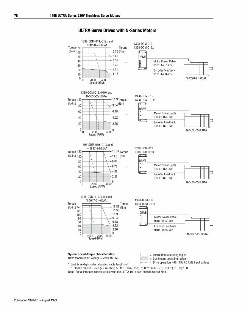
78 1398 ULTRA Series 230V Brushless Servo Motors
Publication 1398-2.1 – August 1999
ULTRA Servo Drives with N-Series Motors
=DRIVE
1398-DDM-0191398-DDM-019x
Motor Power Cable9101-1467-xxx
Encoder Feedback9101-1468-xxx
N-5630-2-H00AA
11.3
9.04
6.78
4.52
2.26
0
100
80
60
40
20
00 2000 4000
1398-DDM-019,-019x andN-5630-2-H00AA
Torque(Nm)
Torque(lb-in.)
Speed (RPM)
=DRIVE
1398-DDM-0191398-DDM-019x
Motor Power Cable9101-1467-xxx
Encoder Feedback9101-1468-xxx
N-5637-2-H00AA
13.56
11.3
9.04
6.78
4.52
2.26
0
120
100
80
60
40
20
00 2000 4000
1398-DDM-019,-019x andN-5637-2-H00AA
Torque(Nm)
Torque(lb-in.)
Speed (RPM)
=DRIVE
1398-DDM-0191398-DDM-019x
Motor Power Cable9101-1467-xxx
Encoder Feedback9101-1468-xxx
N-5647-2-H00AA
15.8213.5611.39.046.784.522.260
14012010080604020
00 1000 2000 3000
1398-DDM-019,-019x andN-5647-2-H00AA
Torque(Nm)
Torque(lb-in.)
Speed (RPM)
= Intermittent operating region= Continuous operating region= Drive operation with 115V AC RMS input voltage
System speed-torque characteristicsDrive module input voltage = 230V AC RMS
* Last three digits select standard cable lengths of: 10 ft (3.0 m)-010; 25 ft (7.7 m)-025; 50 ft (15.0 m)-050; 75 ft (23.0 m)-075; 100 ft (31.0 m)-100Note: Serial interface cables for use with the ULTRA 100 drives cannot exceed 50 ft.
4.52 =DRIVE
1398-DDM-0191398-DDM-019x
Motor Power Cable9101-1467-xxx
Encoder Feedback9101-1468-xxx
N-4220-2-H00AA
6.785.65
3.392.261.130
70605040302010
0 0 2000 4000
1398-DDM-019,-019x andN-4220-2-H00AA
Torque(Nm)
Torque(lb-in.)
Speed (RPM)
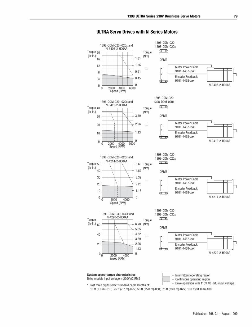
1398 ULTRA Series 230V Brushless Servo Motors 79
Publication 1398-2.1 – August 1999
ULTRA Servo Drives with N-Series Motors
= Motor Power Cable9101-1467-xxx
Encoder Feedback9101-1468-xxx
N-3412-2-H00AA
DRIVE
1398-DDM-020,-020x andN-3412-2-H00AA
Torque(Nm)
Torque(lb-in.)
40
30
20
10
00 2000 4000 6000
3.39
2.26
1.13
0
1398-DDM-0201398-DDM-020x
Speed (RPM)
=
1398-DDM-0201398-DDM-020x
Motor Power Cable9101-1467-xxx
Encoder Feedback9101-1468-xxx
N-4214-2-H00AA
DRIVE
1398-DDM-020,-020x andN-4214-2-H00AA
Torque(Nm)
Torque(lb-in.)
Speed (RPM)
50
40
30
20
10
00 2000 4000
5.65
4.52
3.39
2.26
1.13
0
= Motor Power Cable9101-1467-xxx
Encoder Feedback9101-1468-xxx
N-4220-2-H00AA
1398-DDM-030,-030x andN-4220-2-H00AA
Torque(Nm)
Torque(lb-in.)
Speed (RPM)
60
40
20
0 0 2000 4000
6.78
5.65
4.52
3.39
2.26
1.13
0
= Intermittent operating region= Continuous operating region= Drive operation with 115V AC RMS input voltage
System speed-torque characteristicsDrive module input voltage = 230V AC RMS
* Last three digits select standard cable lengths of: 10 ft (3.0 m)-010; 25 ft (7.7 m)-025; 50 ft (15.0 m)-050; 75 ft (23.0 m)-075; 100 ft (31.0 m)-100
DRIVE
1398-DDM-0301398-DDM-030x
=
1398-DDM-0201398-DDM-020x
Motor Power Cable9101-1467-xxx
Encoder Feedback9101-1468-xxx
N-3406-2-H00AA
DRIVE
1398-DDM-020,-020x andN-3406-2-H00AA
Torque(Nm)
Torque(lb-in.)
Speed (RPM)
1.81
1.36
0.91
0.45
0
20
16
12
8
4
00 2000 4000 6000
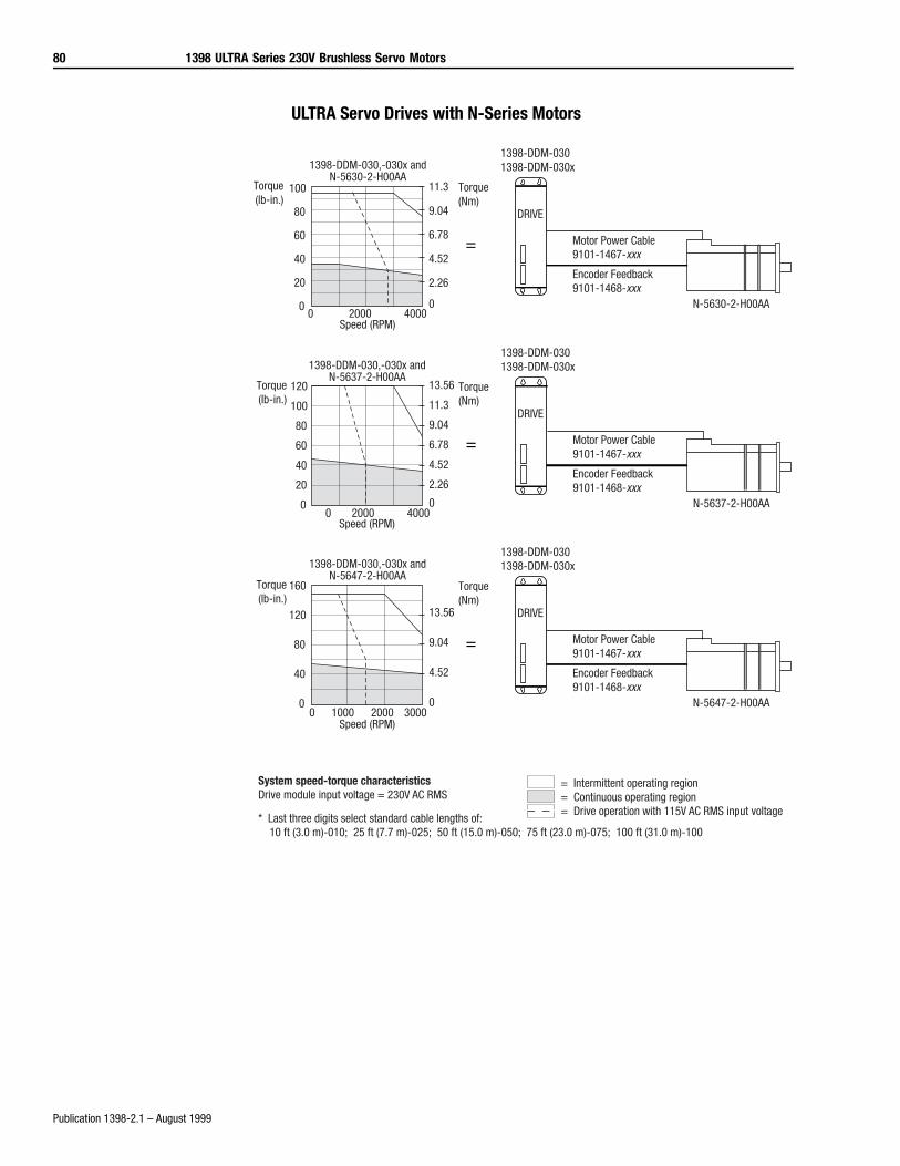
80 1398 ULTRA Series 230V Brushless Servo Motors
Publication 1398-2.1 – August 1999
ULTRA Servo Drives with N-Series Motors
=
1398-DDM-0301398-DDM-030x
Motor Power Cable9101-1467-xxx
Encoder Feedback9101-1468-xxx
N-5637-2-H00AA
DRIVE
1398-DDM-030,-030x andN-5637-2-H00AA
Torque(Nm)
Torque(lb-in.)
Speed (RPM)
120
100
80
60
40
20
00 2000 4000
13.56
11.3
9.04
6.78
4.52
2.26
0
=
1398-DDM-0301398-DDM-030x
Motor Power Cable9101-1467-xxx
Encoder Feedback9101-1468-xxx
N-5647-2-H00AA
DRIVE
1398-DDM-030,-030x andN-5647-2-H00AA
Torque(Nm)
Torque(lb-in.)
Speed (RPM)
160
120
80
40
00 1000 2000 3000
13.56
9.04
4.52
0
= Intermittent operating region= Continuous operating region= Drive operation with 115V AC RMS input voltage
System speed-torque characteristicsDrive module input voltage = 230V AC RMS
* Last three digits select standard cable lengths of: 10 ft (3.0 m)-010; 25 ft (7.7 m)-025; 50 ft (15.0 m)-050; 75 ft (23.0 m)-075; 100 ft (31.0 m)-100
= Motor Power Cable9101-1467-xxx
Encoder Feedback9101-1468-xxx
N-5630-2-H00AA
1398-DDM-030,-030x andN-5630-2-H00AA
Torque(Nm)
Torque(lb-in.)
Speed (RPM)
DRIVE
1398-DDM-0301398-DDM-030x
100
80
60
40
20
00 2000 4000
11.3
9.04
6.78
4.52
2.26
0
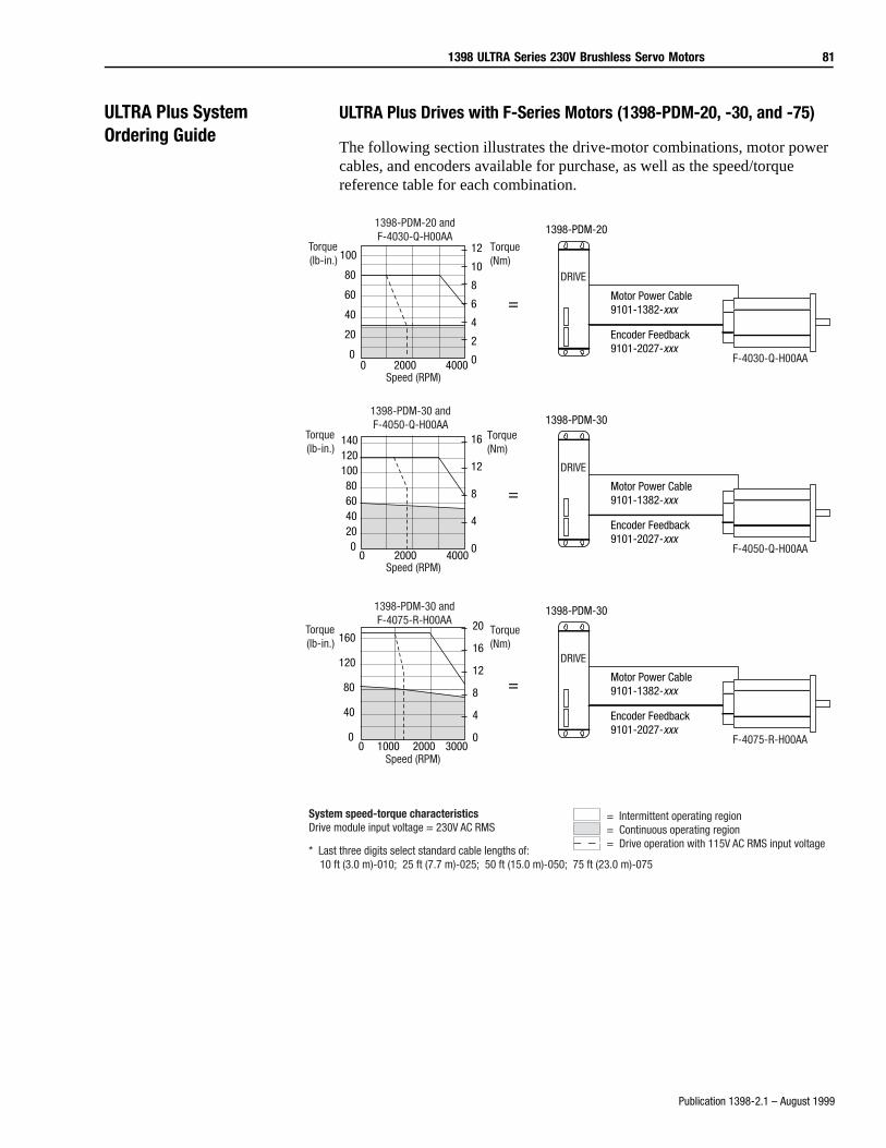
1398 ULTRA Series 230V Brushless Servo Motors 81
Publication 1398-2.1 – August 1999
ULTRA Plus System Ordering Guide
ULTRA Plus Drives with F-Series Motors (1398-PDM-20, -30, and -75)
The following section illustrates the drive-motor combinations, motor power cables, and encoders available for purchase, as well as the speed/torque reference table for each combination.
=
1398-PDM-30
Motor Power Cable9101-1382-xxx
Encoder Feedback9101-2027-xxx
DRIVE
F-4050-Q-H00AA
16
12
8
4
00 2000 4000
140120100806040200
Torque(lb-in.)
Speed (RPM)
1398-PDM-30 andF-4050-Q-H00AA
Torque(Nm)
100
80
60
40
20
0
12
10
8
6
4
2
00 2000 4000
Torque(lb-in.)
Speed (RPM)
1398-PDM-20 andF-4030-Q-H00AA
Torque(Nm)
=
1398-PDM-20
Motor Power Cable9101-1382-xxx
Encoder Feedback9101-2027-xxx
DRIVE
F-4030-Q-H00AA
=
1398-PDM-30
Motor Power Cable9101-1382-xxx
Encoder Feedback9101-2027-xxx
DRIVE
F-4075-R-H00AA
20
16
12
8
4
00 1000 2000 3000
160
120
80
40
0
Torque(lb-in.)
Speed (RPM)
1398-PDM-30 andF-4075-R-H00AA
Torque(Nm)
= Intermittent operating region= Continuous operating region= Drive operation with 115V AC RMS input voltage
System speed-torque characteristicsDrive module input voltage = 230V AC RMS
* Last three digits select standard cable lengths of: 10 ft (3.0 m)-010; 25 ft (7.7 m)-025; 50 ft (15.0 m)-050; 75 ft (23.0 m)-075
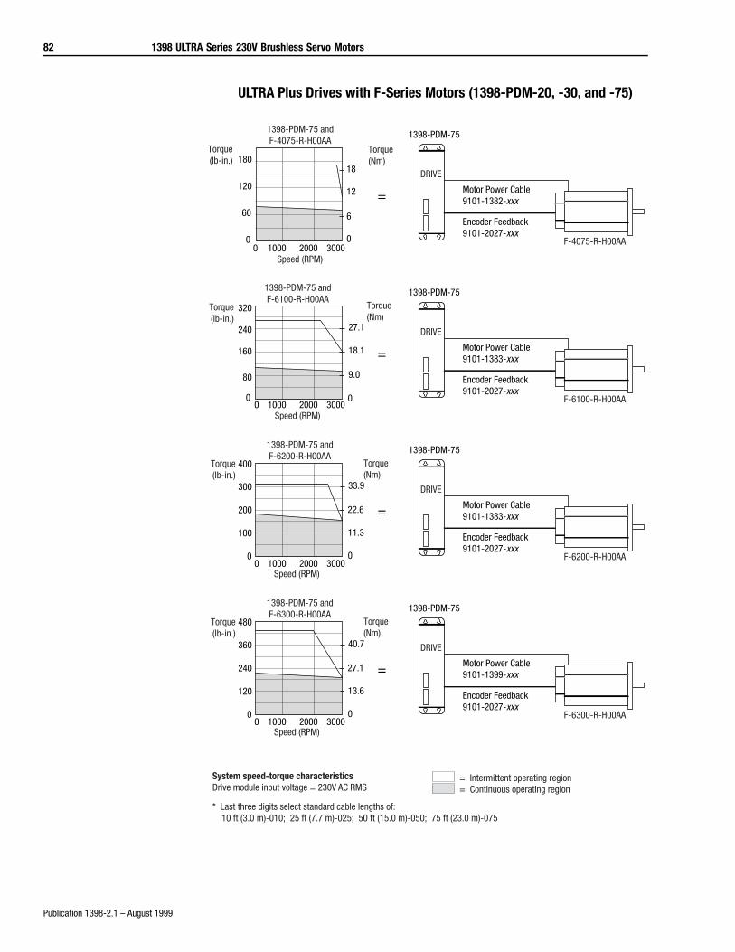
82 1398 ULTRA Series 230V Brushless Servo Motors
Publication 1398-2.1 – August 1999
ULTRA Plus Drives with F-Series Motors (1398-PDM-20, -30, and -75)
=
1398-PDM-75
Motor Power Cable9101-1383-xxx
Encoder Feedback9101-2027-xxx
DRIVE
F-6100-R-H00AA
27.1
18.1
9.0
00 1000 2000 3000
320
240
160
80
0
Torque(lb-in.)
Torque(Nm)
Speed (RPM)
1398-PDM-75 andF-6100-R-H00AA
=
1398-PDM-75
Motor Power Cable9101-1382-xxx
Encoder Feedback9101-2027-xxx
DRIVE
F-4075-R-H00AA
18
12
6
00 1000 2000 3000
180
120
60
0
Torque(lb-in.)
Torque(Nm)
Speed (RPM)
1398-PDM-75 andF-4075-R-H00AA
=
1398-PDM-75
Motor Power Cable9101-1383-xxx
Encoder Feedback9101-2027-xxx
DRIVE
F-6200-R-H00AA
33.9
22.6
11.3
00 1000 2000 3000
300
200
100
0
Torque(lb-in.)
Torque(Nm)
Speed (RPM)
1398-PDM-75 andF-6200-R-H00AA
400
=
1398-PDM-75
Motor Power Cable9101-1399-xxx
Encoder Feedback9101-2027-xxx
DRIVE
F-6300-R-H00AA
40.7
27.1
13.6
00 1000 2000 3000
360
240
120
0
Torque(lb-in.)
Torque(Nm)
Speed (RPM)
1398-PDM-75 andF-6300-R-H00AA
= Intermittent operating region= Continuous operating region
System speed-torque characteristicsDrive module input voltage = 230V AC RMS
* Last three digits select standard cable lengths of: 10 ft (3.0 m)-010; 25 ft (7.7 m)-025; 50 ft (15.0 m)-050; 75 ft (23.0 m)-075
480

1398 ULTRA Series 230V Brushless Servo Motors 83
Publication 1398-2.1 – August 1999
ULTRA Plus Drives with F-Series Motors (1398-PDM-25, -50, -100, and -150)
Torque(lb-in.)
Speed (RPM)
1398-PDM-25 andF-4030-Q-H00AA
Torque(Nm)
=
1398-PDM-25
Motor Power Cable9101-1382-xxx
Encoder Feedback9101-2027-xxx
DRIVE
F-4030-Q-H00AA
12
10
8
6
4
2
00 2000 4000
100
80
60
40
20
0
+PSM
RATING5
=
1398-PDM-50
Motor Power Cable9101-1382-xxx
Encoder Feedback9101-2027-xxx
DRIVE
F-4050-Q-H00AA
Torque(lb-in.)
Speed (RPM)
1398-PDM-50 andF-4050-Q-H00AA
Torque(Nm)
120
80
40
0
16
12
8
4
00 2000 4000
+PSM
RATING8
=
1398-PDM-50
Motor Power Cable9101-1382-xxx
Encoder Feedback9101-2027-xxx
DRIVE
F-4075-R-H00AA
Torque(lb-in.)
Speed (RPM)
1398-PDM-50 andF-4075-R-H00AA
Torque(Nm)
20
16
12
8
4
00 2000
160
120
80
40
0
+PSM
RATING10
= Intermittent operating region= Continuous operating region
System speed-torque characteristicsDrive module input voltage = 230V AC RMS
* Last three digits select standard cable lengths of: 10 ft (3.0 m)-010; 25 ft (7.7 m)-025; 50 ft (15.0 m)-050; 75 ft (23.0 m)-075
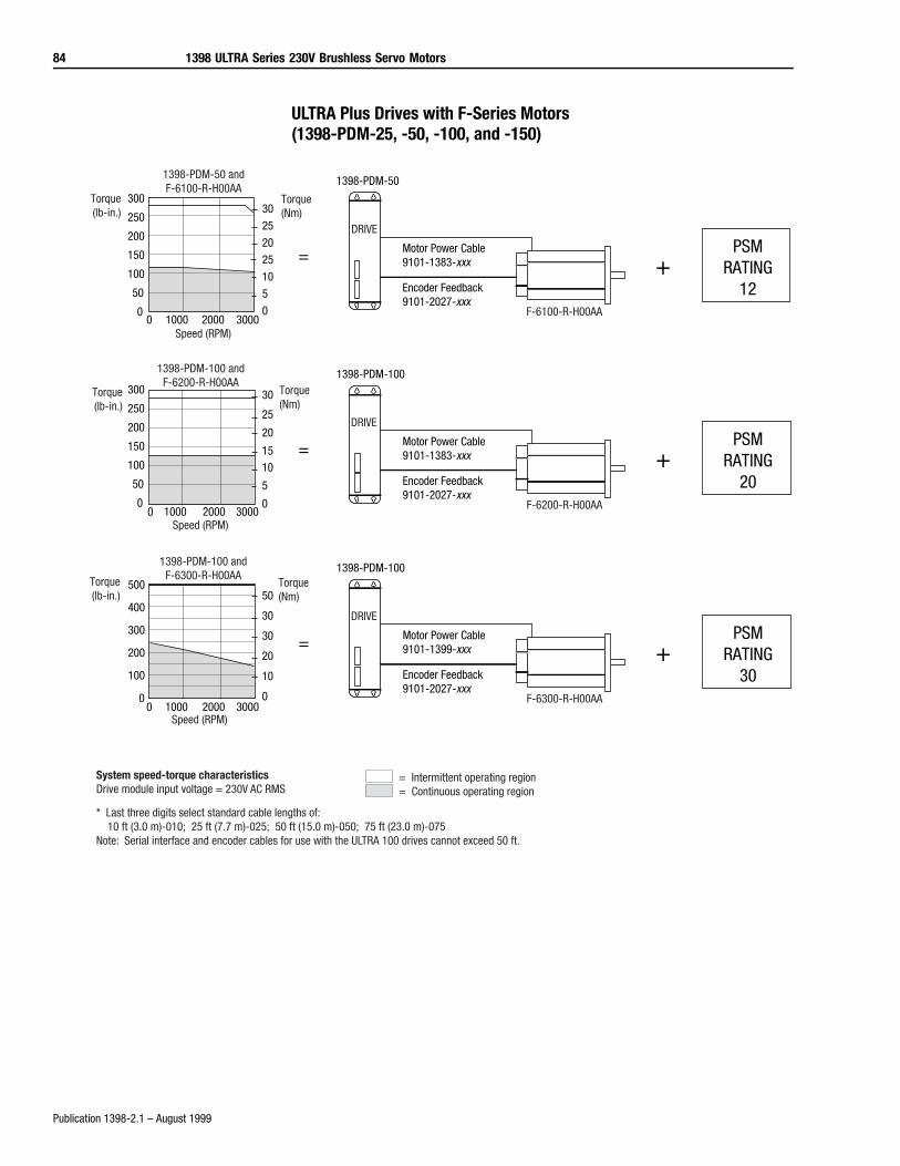
84 1398 ULTRA Series 230V Brushless Servo Motors
Publication 1398-2.1 – August 1999
ULTRA Plus Drives with F-Series Motors (1398-PDM-25, -50, -100, and -150)
= Intermittent operating region= Continuous operating region
System speed-torque characteristicsDrive module input voltage = 230V AC RMS
* Last three digits select standard cable lengths of: 10 ft (3.0 m)-010; 25 ft (7.7 m)-025; 50 ft (15.0 m)-050; 75 ft (23.0 m)-075Note: Serial interface and encoder cables for use with the ULTRA 100 drives cannot exceed 50 ft.
=
1398-PDM-100
Motor Power Cable9101-1383-xxx
Encoder Feedback9101-2027-xxx
DRIVE
F-6200-R-H00AA
30
25
20
1510
5
00 1000 2000 3000
300
250
200
150
100
50
0
Torque(lb-in.)
Torque(Nm)
Speed (RPM)
1398-PDM-100 andF-6200-R-H00AA
+PSM
RATING20
=
1398-PDM-50
Motor Power Cable9101-1383-xxx
Encoder Feedback9101-2027-xxx
DRIVE
F-6100-R-H00AA
Torque(lb-in.)
Torque(Nm)
Speed (RPM)
1398-PDM-50 andF-6100-R-H00AA
+PSM
RATING12
30
25
20
25
10
5
00 1000 2000 3000
300
250
200
150
100
50
0
=
1398-PDM-100
Motor Power Cable9101-1399-xxx
Encoder Feedback9101-2027-xxx
DRIVE
F-6300-R-H00AA
Torque(lb-in.)
Torque(Nm)
Speed (RPM)
1398-PDM-100 andF-6300-R-H00AA
+PSM
RATING30
50
30
30
20
10
00 1000 2000 3000
500
400
300
200
100
0
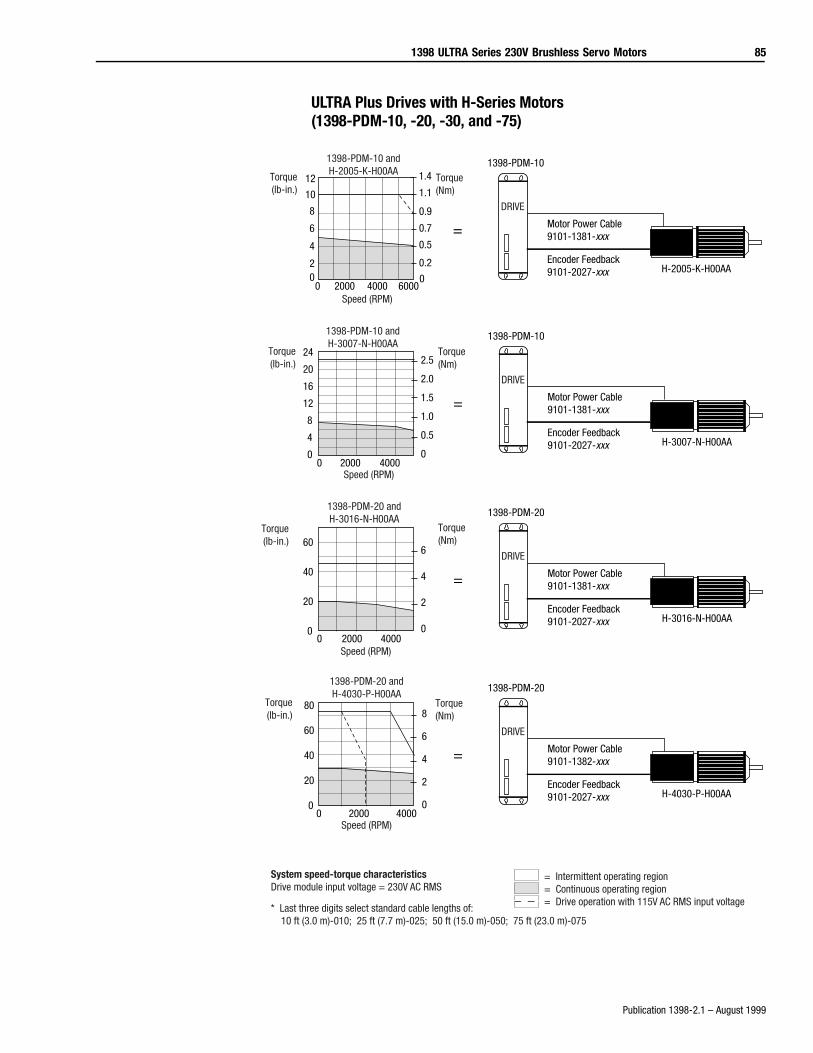
1398 ULTRA Series 230V Brushless Servo Motors 85
Publication 1398-2.1 – August 1999
ULTRA Plus Drives with H-Series Motors (1398-PDM-10, -20, -30, and -75)
Torque(lb-in.)
Torque(Nm)
Speed (RPM)
1398-PDM-10 andH-2005-K-H00AA
=
1398-PDM-10
Motor Power Cable9101-1381-xxx
Encoder Feedback9101-2027-xxx H-2005-K-H00AA
DRIVE
0 2000 4000 6000
0.9
0.7
0.5
0.2
0
12
8
4
0
=
1398-PDM-10
Motor Power Cable9101-1381-xxx
Encoder Feedback9101-2027-xxx H-3007-N-H00AA
DRIVE
Torque(lb-in.)
Torque(Nm)
Speed (RPM)
1398-PDM-10 andH-3007-N-H00AA
0 2000 4000
2.5
2.0
1.5
1.0
0.5
0
24
20
16
12
8
4
0
=
1398-PDM-20
Motor Power Cable9101-1381-xxx
Encoder Feedback9101-2027-xxx H-3016-N-H00AA
DRIVE
Torque(lb-in.)
Torque(Nm)
Speed (RPM)
1398-PDM-20 andH-3016-N-H00AA
0 2000 4000
6
4
2
0
60
40
20
0
=
1398-PDM-20
Motor Power Cable9101-1382-xxx
Encoder Feedback9101-2027-xxx H-4030-P-H00AA
DRIVE
Torque(lb-in.)
Torque(Nm)
Speed (RPM)
1398-PDM-20 andH-4030-P-H00AA
8
6
4
2
00 2000 4000
80
60
40
20
0
= Intermittent operating region= Continuous operating region= Drive operation with 115V AC RMS input voltage
System speed-torque characteristicsDrive module input voltage = 230V AC RMS
* Last three digits select standard cable lengths of: 10 ft (3.0 m)-010; 25 ft (7.7 m)-025; 50 ft (15.0 m)-050; 75 ft (23.0 m)-075
10
6
2
1.4
1.1
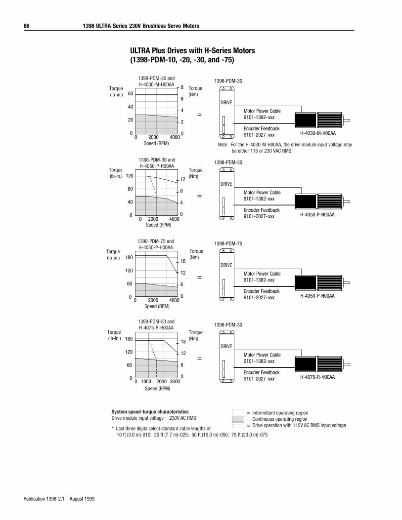
86 1398 ULTRA Series 230V Brushless Servo Motors
Publication 1398-2.1 – August 1999
ULTRA Plus Drives with H-Series Motors (1398-PDM-10, -20, -30, and -75)
=
1398-PDM-30
Motor Power Cable9101-1382-xxx
Encoder Feedback9101-2027-xxx H-4050-P-H00AA
DRIVE
Torque(lb-in.)
Torque(Nm)
Speed (RPM)
1398-PDM-30 andH-4050-P-H00AA
12
8
4
0
120
80
40
00 2000 4000
=
1398-PDM-75
Motor Power Cable9101-1382-xxx
Encoder Feedback9101-2027-xxx H-4050-P-H00AA
DRIVE
Torque(lb-in.)
Torque(Nm)
Speed (RPM)
1398-PDM-75 andH-4050-P-H00AA
18
12
6
0
180
120
60
00 2000 4000
Torque(lb-in.)
Torque(Nm)
Speed (RPM)
1398-PDM-30 andH-4030-M-H00AA
=
1398-PDM-30
Motor Power Cable9101-1382-xxx
Encoder Feedback9101-2027-xxx H-4030-M-H00AA
DRIVE
0 2000 4000
8
6
4
2
0
60
40
20
0
Note: For the H-4030-M-H00AA, the drive module input voltage may be either 115 or 230 VAC RMS.
=
1398-PDM-30
Motor Power Cable9101-1382-xxx
Encoder Feedback9101-2027-xxx H-4075-R-H00AA
DRIVE
Torque(lb-in.)
Torque(Nm)
Speed (RPM)
1398-PDM-30 andH-4075-R-H00AA
18
12
6
00 1000 2000 3000
180
120
60
0
= Intermittent operating region= Continuous operating region= Drive operation with 115V AC RMS input voltage
System speed-torque characteristicsDrive module input voltage = 230V AC RMS
* Last three digits select standard cable lengths of: 10 ft (3.0 m)-010; 25 ft (7.7 m)-025; 50 ft (15.0 m)-050; 75 ft (23.0 m)-075
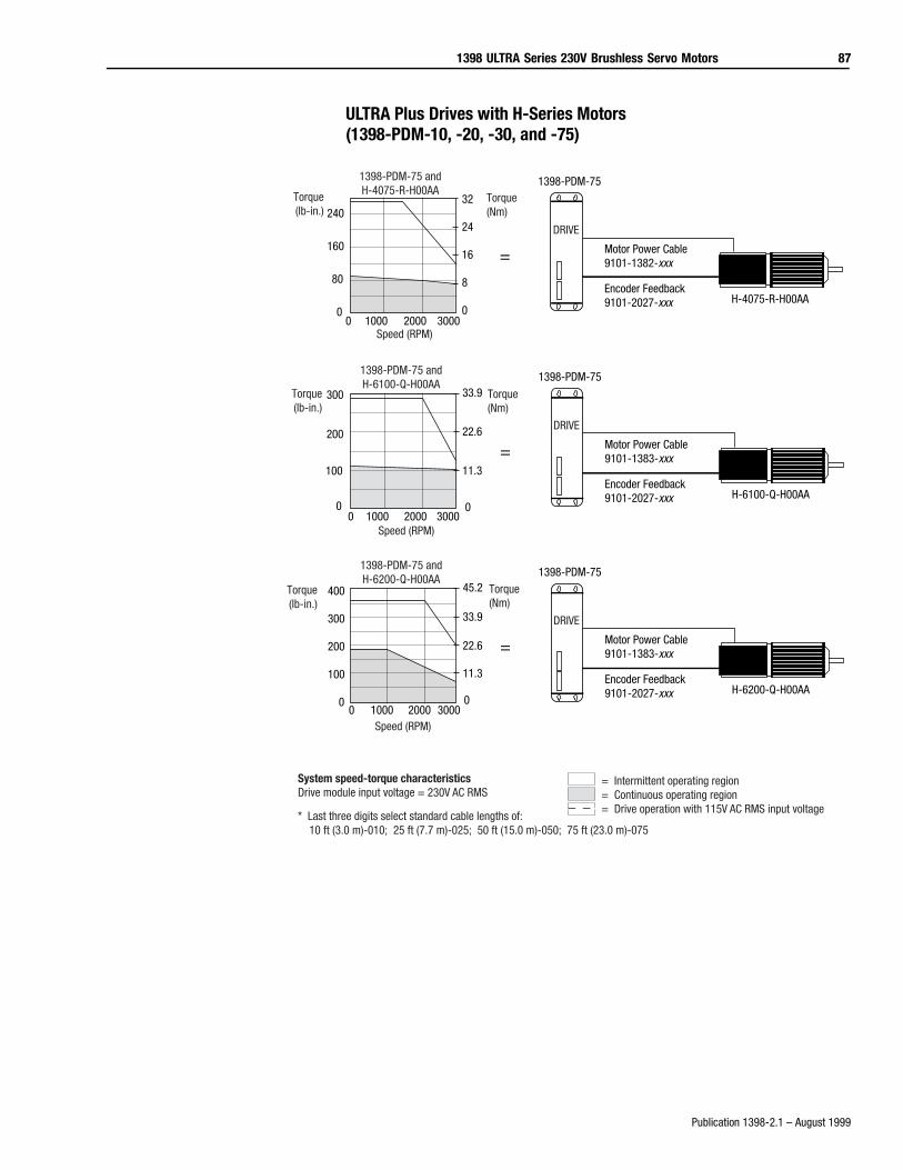
1398 ULTRA Series 230V Brushless Servo Motors 87
Publication 1398-2.1 – August 1999
ULTRA Plus Drives with H-Series Motors (1398-PDM-10, -20, -30, and -75)
Torque(lb-in.)
Torque(Nm)
Speed (RPM)
1398-PDM-75 andH-4075-R-H00AA
=
1398-PDM-75
Motor Power Cable9101-1382-xxx
Encoder Feedback9101-2027-xxx H-4075-R-H00AA
DRIVE
32
24
16
8
00 1000 2000 3000
240
160
80
0
=
1398-PDM-75
Motor Power Cable9101-1383-xxx
Encoder Feedback9101-2027-xxx H-6100-Q-H00AA
DRIVE
Torque(lb-in.)
Torque(Nm)
Speed (RPM)
1398-PDM-75 andH-6100-Q-H00AA
33.9
22.6
11.3
00 1000 2000 3000
300
200
100
0
=
1398-PDM-75
Motor Power Cable9101-1383-xxx
Encoder Feedback9101-2027-xxx H-6200-Q-H00AA
DRIVE
Torque(lb-in.)
Torque(Nm)
Speed (RPM)
1398-PDM-75 andH-6200-Q-H00AA
45.2
33.9
22.6
11.3
0
400
300
200
100
00 1000 2000 3000
= Intermittent operating region= Continuous operating region= Drive operation with 115V AC RMS input voltage
System speed-torque characteristicsDrive module input voltage = 230V AC RMS
* Last three digits select standard cable lengths of: 10 ft (3.0 m)-010; 25 ft (7.7 m)-025; 50 ft (15.0 m)-050; 75 ft (23.0 m)-075
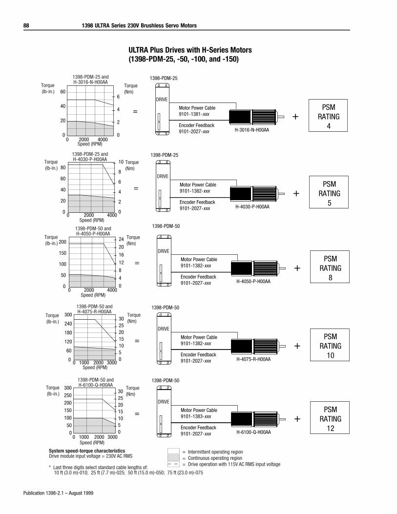
88 1398 ULTRA Series 230V Brushless Servo Motors
Publication 1398-2.1 – August 1999
ULTRA Plus Drives with H-Series Motors (1398-PDM-25, -50, -100, and -150)
Torque(lb-in.)
Torque(Nm)
Speed (RPM)
1398-PDM-25 andH-4030-P-H00AA
=
1398-PDM-25
Motor Power Cable9101-1382-xxx
Encoder Feedback9101-2027-xxx H-4030-P-H00AA
DRIVE
10
8
6
4
2
00 2000 4000
80
60
40
20
0
+PSM
RATING5
=
1398-PDM-50
Motor Power Cable9101-1382-xxx
Encoder Feedback9101-2027-xxx H-4050-P-H00AA
DRIVE
Torque(lb-in.)
Torque(Nm)
Speed (RPM)
1398-PDM-50 andH-4050-P-H00AA
24
20
16
12
8
4
00 2000 4000
200
150
100
50
0
+PSM
RATING8
=
1398-PDM-50
Motor Power Cable9101-1382-xxx
Encoder Feedback9101-2027-xxx H-4075-R-H00AA
DRIVE
Torque(lb-in.)
Torque(Nm)
Speed (RPM)
1398-PDM-50 andH-4075-R-H00AA
302520151050
0 1000 2000 3000
300
240
180
120
60
0
+PSM
RATING10
=
1398-PDM-50
Motor Power Cable9101-1383-xxx
Encoder Feedback9101-2027-xxx H-6100-Q-H00AA
DRIVE
Torque(lb-in.)
Torque(Nm)
Speed (RPM)
1398-PDM-50 andH-6100-Q-H00AA
302520151050
0 1000 2000 3000
300
250
200
150
100
50
0
+PSM
RATING12
= Intermittent operating region= Continuous operating region= Drive operation with 115V AC RMS input voltage
System speed-torque characteristicsDrive module input voltage = 230V AC RMS
* Last three digits select standard cable lengths of: 10 ft (3.0 m)-010; 25 ft (7.7 m)-025; 50 ft (15.0 m)-050; 75 ft (23.0 m)-075
=
1398-PDM-25
Motor Power Cable9101-1381-xxx
Encoder Feedback9101-2027-xxx H-3016-N-H00AA
DRIVE
Torque(lb-in.)
Torque(Nm)
Speed (RPM)
1398-PDM-25 andH-3016-N-H00AA
6
4
2
00 2000 4000
60
40
20
0
+PSM
RATING4
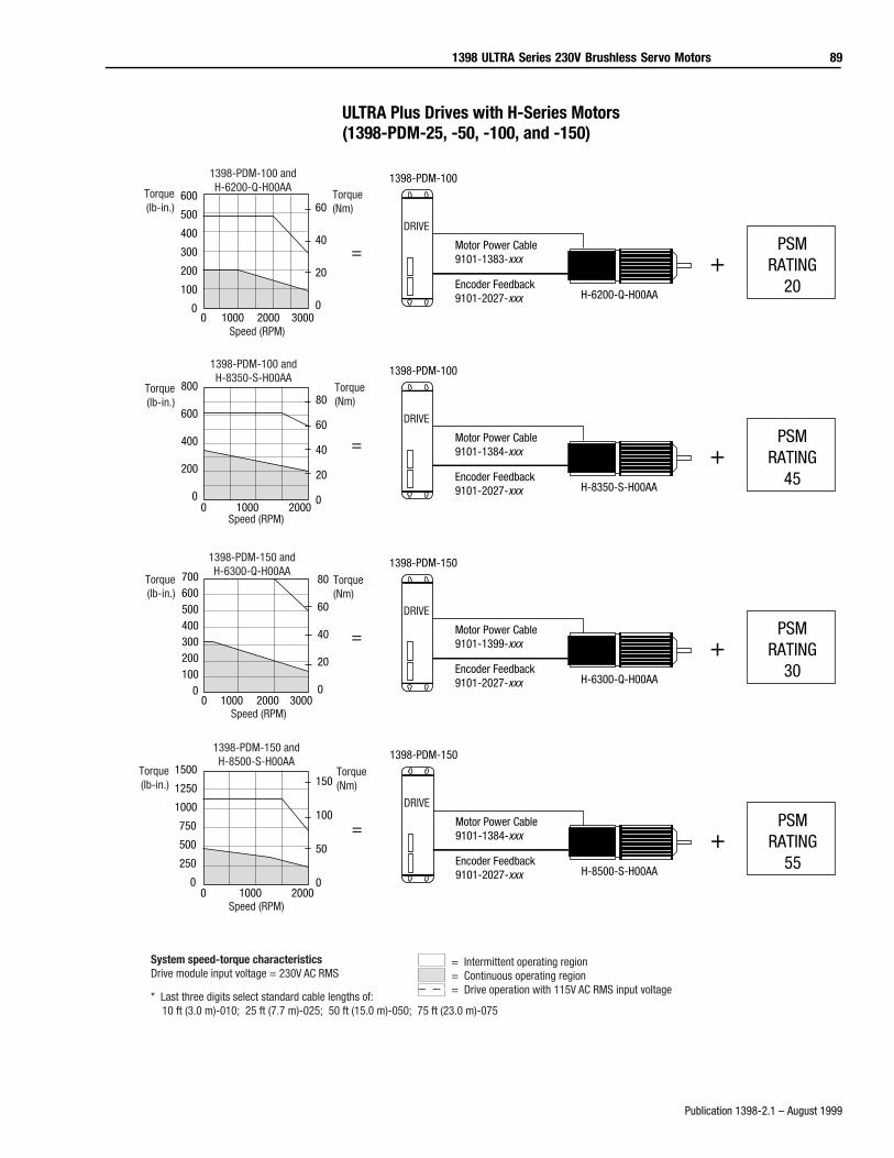
1398 ULTRA Series 230V Brushless Servo Motors 89
Publication 1398-2.1 – August 1999
ULTRA Plus Drives with H-Series Motors (1398-PDM-25, -50, -100, and -150)
Torque(lb-in.)
Torque(Nm)
Speed (RPM)
1398-PDM-100 andH-6200-Q-H00AA
=
1398-PDM-100
Motor Power Cable9101-1383-xxx
Encoder Feedback9101-2027-xxx H-6200-Q-H00AA
DRIVE
+PSM
RATING20
60
40
20
00 1000 2000 3000
600
500
400
300
200
100
0
=
1398-PDM-150
Motor Power Cable9101-1399-xxx
Encoder Feedback9101-2027-xxx H-6300-Q-H00AA
DRIVE
Torque(lb-in.)
Torque(Nm)
Speed (RPM)
1398-PDM-150 andH-6300-Q-H00AA
+PSM
RATING30
80
60
40
20
00 1000 2000 3000
700600500400300200100
0
=
1398-PDM-100
Motor Power Cable9101-1384-xxx
Encoder Feedback9101-2027-xxx H-8350-S-H00AA
DRIVE
Torque(lb-in.)
Torque(Nm)
Speed (RPM)
1398-PDM-100 andH-8350-S-H00AA
+PSM
RATING45
80
60
40
20
00 1000 2000
800
600
400
200
0
=
1398-PDM-150
Motor Power Cable9101-1384-xxx
Encoder Feedback9101-2027-xxx H-8500-S-H00AA
DRIVE
Torque(lb-in.)
Torque(Nm)
Speed (RPM)
1398-PDM-150 andH-8500-S-H00AA
+PSM
RATING55
150
100
50
00 1000 2000
1500
1250
1000
750
500
250
0
= Intermittent operating region= Continuous operating region= Drive operation with 115V AC RMS input voltage
System speed-torque characteristicsDrive module input voltage = 230V AC RMS
* Last three digits select standard cable lengths of: 10 ft (3.0 m)-010; 25 ft (7.7 m)-025; 50 ft (15.0 m)-050; 75 ft (23.0 m)-075
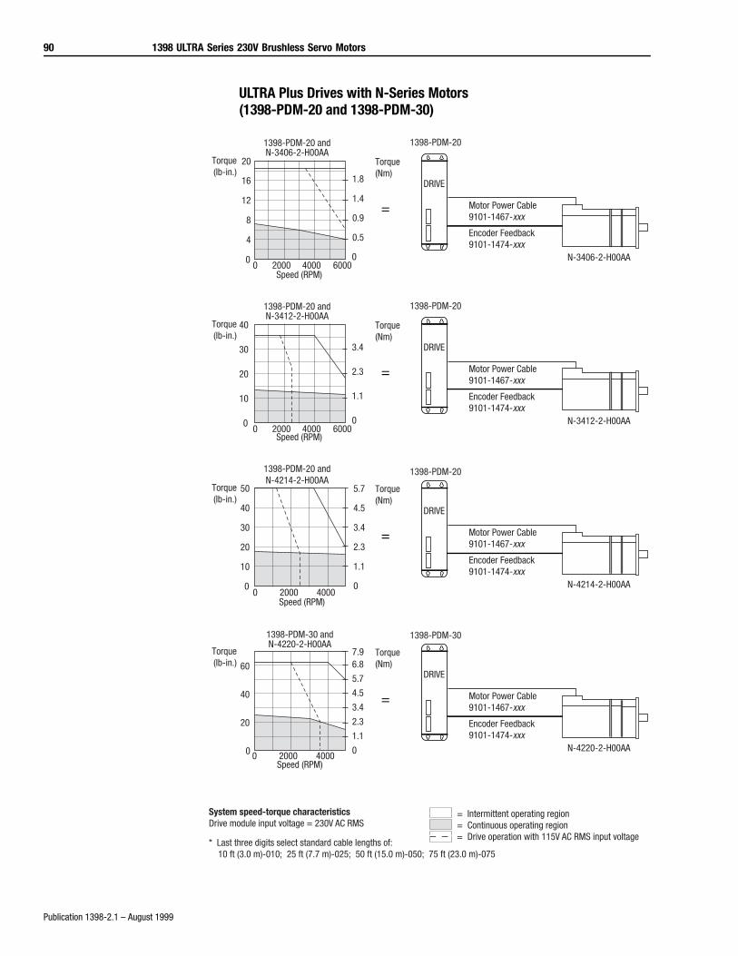
90 1398 ULTRA Series 230V Brushless Servo Motors
Publication 1398-2.1 – August 1999
ULTRA Plus Drives with N-Series Motors (1398-PDM-20 and 1398-PDM-30)
= Motor Power Cable9101-1467-xxx
Encoder Feedback9101-1474-xxx
N-3406-2-H00AA
DRIVE
1398-PDM-20 andN-3406-2-H00AA
Torque(Nm)
Torque(lb-in.)
16
12
8
4
00 2000 4000 6000
1.4
0.9
0.5
0
1398-PDM-20
Speed (RPM)
= Intermittent operating region= Continuous operating region= Drive operation with 115V AC RMS input voltage
System speed-torque characteristicsDrive module input voltage = 230V AC RMS
* Last three digits select standard cable lengths of: 10 ft (3.0 m)-010; 25 ft (7.7 m)-025; 50 ft (15.0 m)-050; 75 ft (23.0 m)-075
20
1.8
= Motor Power Cable9101-1467-xxx
Encoder Feedback9101-1474-xxx
N-3412-2-H00AA
DRIVE
1398-PDM-20 andN-3412-2-H00AA
Torque(Nm)
Torque(lb-in.)
40
30
20
10
00 2000 4000 6000
3.4
2.3
1.1
0
1398-PDM-20
Speed (RPM)
=
1398-PDM-20
Motor Power Cable9101-1467-xxx
Encoder Feedback9101-1474-xxx
N-4214-2-H00AA
DRIVE
1398-PDM-20 andN-4214-2-H00AA
Torque(Nm)
Torque(lb-in.)
Speed (RPM)
50
40
30
20
10
00 2000 4000
5.7
4.5
3.4
2.3
1.1
0
= Motor Power Cable9101-1467-xxx
Encoder Feedback9101-1474-xxx
N-4220-2-H00AA
1398-PDM-30 andN-4220-2-H00AA
Torque(Nm)
Torque(lb-in.)
Speed (RPM)
60
40
20
0 0 2000 4000
6.8
5.7
4.5
3.4
2.3
1.1
0
DRIVE
1398-PDM-30
7.9

1398 ULTRA Series 230V Brushless Servo Motors 91
Publication 1398-2.1 – August 1999
ULTRA Plus Drives with N-Series Motors (1398-PDM-20 and 1398-PDM-30)
=
1398-PDM-30
Motor Power Cable9101-1467-xxx
Encoder Feedback9101-1474-xxx
N-5637-2-H00AA
DRIVE
1398-PDM-30 andN-5637-2-H00AA
Torque(Nm)
Torque(lb-in.)
Speed (RPM)
120
100
80
60
40
20
00 2000 4000
13.6
11.3
9.0
6.8
4.5
2.3
0
=
1398-PDM-30
Motor Power Cable9101-1467-xxx
Encoder Feedback9101-1474-xxx
N-5647-2-H00AA
DRIVE
1398-PDM-30 andN-5647-2-H00AA
Torque(Nm)
Torque(lb-in.)
Speed (RPM)
160
120
80
40
00 1000 2000 3000
13.6
9.0
4.5
0
= Intermittent operating region= Continuous operating region= Drive operation with 115V AC RMS input voltage
System speed-torque characteristicsDrive module input voltage = 230V AC RMS
* Last three digits select standard cable lengths of: 10 ft (3.0 m)-010; 25 ft (7.7 m)-025; 50 ft (15.0 m)-050; 75 ft (23.0 m)-075
= Motor Power Cable9101-1467-xxx
Encoder Feedback9101-1474-xxx
N-5630-2-H00AA
1398-PDM-30 andN-5630-2-H00AA
Torque(Nm)
Torque(lb-in.)
Speed (RPM)
DRIVE
1398-PDM-30
100
80
60
40
20
00 2000 4000
11.3
9.0
6.8
4.5
2.3
0
18.1
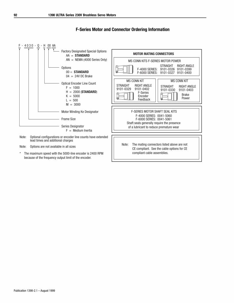
92 1398 ULTRA Series 230V Brushless Servo Motors
Publication 1398-2.1 – August 1999
F-Series Motor and Connector Ordering Information
MOTOR MATING CONNECTORS
MS CONN KITS F-SERIES MOTOR POWER
MS CONN KIT MS CONN KIT
F-SERIES MOTOR SHAFT SEAL KITS
Shaft seals generally require the presenceof a lubricant to reduce premature wear
STRAIGHT RIGHT ANGLEF-4000 SERIES: 9101-0326 9101-0399F-6000 SERIES: 9101-0327 9101-0400
STRAIGHT RIGHT ANGLE9101-0329 9101-0402
F-SeriesEncoderFeedback
STRAIGHT RIGHT ANGLE9101-0330 9101-0403
Brake Power
F-4000 SERIES: 0041-5060F-6000 SERIES: 0041-5061
Factory Designated Special OptionsAA = STANDARDAN = NEMA (4000 Series Only)
Options00 = STANDARD04 = 24V DC Brake
Optical Encoder Line CountF = 1000H = 2000 (STANDARD)K = 5000L = 500M = 3000
Motor Winding Ke Designator
Frame Size
Series DesignatorF = Medium Inertia
F - 4 0 3 0 - Q - H 00 AA
Note: Optional configurations or encoder line counts have extendedlead times and additional charges
Note: Options are not available in all sizes
* The maximum speed with the 5000-line encoder is 2400 RPM because of the frequency output limit of the encoder.
Note: The mating connectors listed above are not CE compliant. See the cable options for CE compliant cable assemblies.
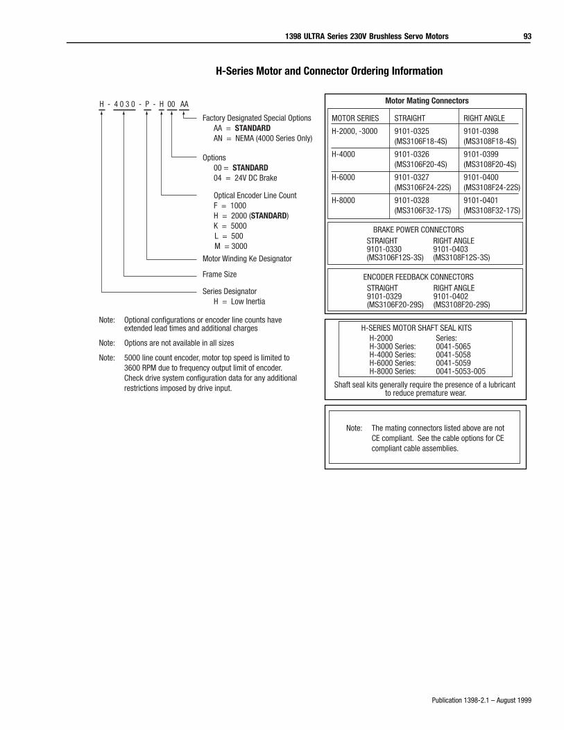
1398 ULTRA Series 230V Brushless Servo Motors 93
Publication 1398-2.1 – August 1999
H-Series Motor and Connector Ordering Information
MOTOR SERIES STRAIGHT RIGHT ANGLE
H-2000, -3000 9101-0325 9101-0398(MS3106F18-4S) (MS3108F18-4S)
H-4000 9101-0326 9101-0399(MS3106F20-4S) (MS3108F20-4S)
H-6000 9101-0327 9101-0400(MS3106F24-22S) (MS3108F24-22S)
H-8000 9101-0328 9101-0401(MS3106F32-17S) (MS3108F32-17S)
Factory Designated Special OptionsAA = STANDARDAN = NEMA (4000 Series Only)
Options00 = STANDARD04 = 24V DC Brake
Optical Encoder Line CountF = 1000H = 2000 (STANDARD)K = 5000
L = 500 M = 3000
Motor Winding Ke Designator
Frame Size
Series DesignatorH = Low Inertia
H - 4 0 3 0 - P - H 00 AA
Note: Optional configurations or encoder line counts have extended lead times and additional charges
Note: Options are not available in all sizes
Note: 5000 line count encoder, motor top speed is limited to 3600 RPM due to frequency output limit of encoder. Check drive system configuration data for any additional restrictions imposed by drive input.
Motor Mating Connectors
BRAKE POWER CONNECTORSSTRAIGHT RIGHT ANGLE9101-0330 9101-0403(MS3106F12S-3S) (MS3108F12S-3S)
ENCODER FEEDBACK CONNECTORSSTRAIGHT RIGHT ANGLE9101-0329 9101-0402(MS3106F20-29S) (MS3108F20-29S)
H-SERIES MOTOR SHAFT SEAL KITSH-2000 Series:H-3000 Series: 0041-5065H-4000 Series: 0041-5058H-6000 Series: 0041-5059H-8000 Series: 0041-5053-005
Shaft seal kits generally require the presence of a lubricant to reduce premature wear.
Note: The mating connectors listed above are not CE compliant. See the cable options for CE compliant cable assemblies.
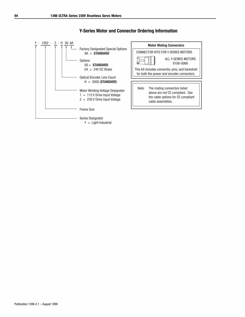
94 1398 ULTRA Series 230V Brushless Servo Motors
Publication 1398-2.1 – August 1999
Y-Series Motor and Connector Ordering Information
Factory Designated Special OptionsAA = STANDARD
Options00 = STANDARD04 = 24V DC Brake
Optical Encoder Line CountH = 2000 (STANDARD)
Motor Winding Voltage Designator1 = 115 V Drive Input Voltage2 = 230 V Drive Input Voltage
Frame Size
Series DesignatorY = Light Industrial
Y - 1002 - 2 - H 00 AAMotor Mating Connectors
CONNECTOR KITS FOR Y-SERIES MOTORS
ALL Y-SERIES MOTORS9106-0066
This kit includes connector, pins, and backshellfor both the power and encoder connectors.
Note: The mating connectors listed above are not CE compliant. See the cable options for CE compliant cable assemblies.
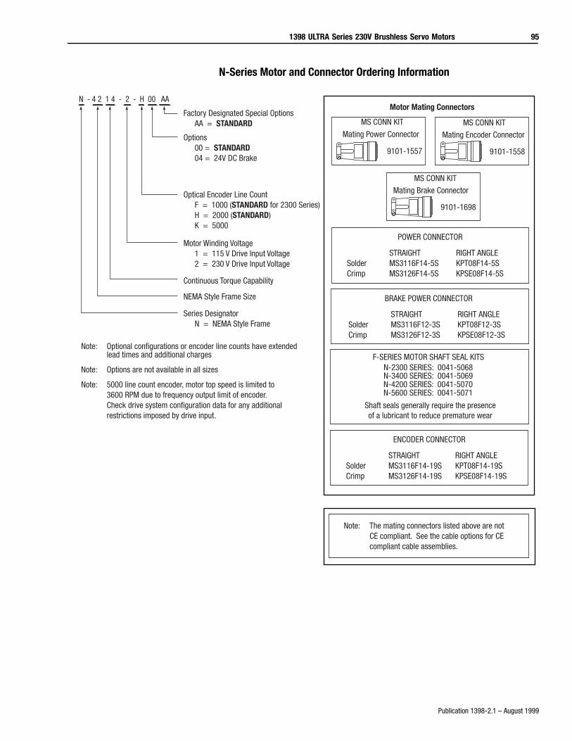
1398 ULTRA Series 230V Brushless Servo Motors 95
Publication 1398-2.1 – August 1999
N-Series Motor and Connector Ordering Information
MS CONN KIT
Mating Power Connector
9101-1557
MS CONN KIT
Mating Encoder Connector
9101-1558
Factory Designated Special OptionsAA = STANDARD
Options00 = STANDARD04 = 24V DC Brake
Optical Encoder Line CountF = 1000 (STANDARD for 2300 Series)H = 2000 (STANDARD)K = 5000
Motor Winding Voltage1 = 115 V Drive Input Voltage2 = 230 V Drive Input Voltage
Continuous Torque Capability
NEMA Style Frame Size
N - 4 2 1 4 - 2 - H 00 AA
Note: Optional configurations or encoder line counts have extendedlead times and additional charges
Note: Options are not available in all sizes
Series DesignatorN = NEMA Style Frame
Note: 5000 line count encoder, motor top speed is limited to 3600 RPM due to frequency output limit of encoder. Check drive system configuration data for any additional restrictions imposed by drive input.
Motor Mating Connectors
POWER CONNECTOR
STRAIGHT RIGHT ANGLESolder MS3116F14-5S KPT08F14-5SCrimp MS3126F14-5S KPSE08F14-5S
ENCODER CONNECTOR
STRAIGHT RIGHT ANGLESolder MS3116F14-19S KPT08F14-19SCrimp MS3126F14-19S KPSE08F14-19S
Note: The mating connectors listed above are not CE compliant. See the cable options for CE compliant cable assemblies.
BRAKE POWER CONNECTOR
STRAIGHT RIGHT ANGLESolder MS3116F12-3S KPT08F12-3SCrimp MS3126F12-3S KPSE08F12-3S
MS CONN KIT
Mating Brake Connector
9101-1698
F-SERIES MOTOR SHAFT SEAL KITS
Shaft seals generally require the presenceof a lubricant to reduce premature wear
N-2300 SERIES: 0041-5068N-3400 SERIES: 0041-5069N-4200 SERIES: 0041-5070N-5600 SERIES: 0041-5071
96 1398 ULTRA Series 230V Brushless Servo Motors
Publication 1398-2.1 – August 1999
1398 ULTRA Series 230V Brushless Servo Motors 97
Publication 1398-2.1 – August 1999

98 1398 ULTRA Series 230V Brushless Servo Motors
Publication 1398-2.1 – August 1999
For more information refer to our web site: www.ab.com/motionULTRA Series, ULTRA 100, and ULTRA 200 are registered trademarks of Allen-Bradley Company, Inc.
Publication 1398-2.1 – August 1999 Supersedes Publication 1398-2.0 - February 1999 1999 Rockwell International. All Rights Reserved. Printed in USA