14 in. (355 mm) band saw scie À ruban 355 mm (14 po) sierra de cinta...
TRANSCRIPT
1
14 IN. (355 MM) BAND SAWSCIE À RUBAN 355 MM (14 PO)SIERRA DE CINTA PARABRANCO DE 355 MM (14 PULG.)
CATALOG NUMBERPCB330BS
Instruction ManualManuel d’instructionsManual de instrucciones
www.portercable.com
INSTRUCTIVO DE OPERACIÓN, CENTROS DE SERVICIO Y PÓLIZA DE GARANTÍA. ADVERTENCIA: LÉASE ESTE INSTRUCTIVO ANTES DE USAR EL PRODUCTO.

2
TABLE OF CONTENTSSECTION PAGEPRODUCT SPECIFICATIONS ....................................................................................... 2CALIFORNIA PROPOSITION 65 ................................................................................... 2SAFETY GUIDELINES - DEFINITIONS ......................................................................... 3POWER TOOL SAFETY ................................................................................................. 4BAND SAW SAFETY ...................................................................................................... 5ELECTRICAL REQUIREMENTS AND SAFETY ............................................................ 6TOOLS NEEDED FOR ASSEMBLY ............................................................................... 7CARTON CONTENTS .................................................................................................... 7KNOW YOUR BAND SAW ............................................................................................. 9GLOSSARY OF TERMS ................................................................................................. 10ASSEMBLY AND ADJUSTMENTS ................................................................................. 11OPERATION ................................................................................................................... 18MAINTENANCE .............................................................................................................. 21TROUBLESHOOTING GUIDE ....................................................................................... 22ACCESSORIES AND ATTACHMENTS .......................................................................... 24PARTS LIST .................................................................................................................... 25WARRANTY ................................................................................................................... 28
MOTOR BLADE Amps ............ 10 / 5 AMP Width ................. 1/8, 1/4, 3/8, 1/2 in. Voltage ......... 120 / 240 V (3.2, 6.4, 9.5, 12.7 mm) Hz ................. 60 Length ............... 93-1/2 in. (2374.9 mm) Horsepower .. 1.5 HP (Max. Developed) CUTTING CAPACITY Speed ........... 1630/2730 Feet per minute (No load) Throat ................ 13-5/8 in. (346 mm) Type .............. Induction Height ................ 6 in. (152.4 mm)DRIVE BELT A-26 SAWDUST PORT 2-1/2 in. O.D. (63.5 mm)TABLE SIZE 16 x 16 in. (406.4 x 406.4 mm)
PRODUCT SPECIFICATIONS
To avoid electrical hazards, fire hazards or damage to the tool, use proper circuit protection. Use a separate electrical circuit for your tools. This band saw is wired at the factory for 110-120/220-240 Volt operation. It must be connected to a 110-120 Volt / 10 Ampere or 220-240 Volt / 5 Ampere time delay fuse or circuit breaker. To avoid shock or fire, replace power cord immediately if it is worn, cut or damaged in any way.
Some dust created by power sanding, sawing, grinding, drilling and other construction activities contains chemicals known to the state of California to cause cancer, birth defects or other reproductive harm. Some examples of these chemicals are:
● Lead from lead-based paints,● Crystalline silica from bricks and cement and other masonry products, and● Arsenic and chromium from chemically-treated lumber.
Your risk from these exposures varies, depending on how often you do this type of work. To reduce your exposure to these chemicals: work in a well ventilated area, and work with approved safety equipment, such as those dust masks that are specially designed to filter out microscopic particles.Avoid prolonged contact with dust from power sanding, sawing, grinding, drilling and other construction activities. Wear protective clothing and wash exposed areas with soap and water. Allowing dust to get into your mouth, eyes, or lay on the skin may promote absorption of harmful chemicals.
Use of this tool can generate and/or disperse dust, which may cause serious and permanent respiratory or other injury. Always use NIOSH/
OSHA approved respiratory protection appropriate for the dust exposure. Direct particles away from face and body.2014/08 Printed in Taiwan
WARNING!
CALIFORNIA PROPOSITION 65 WARNING!
WARNING!
3
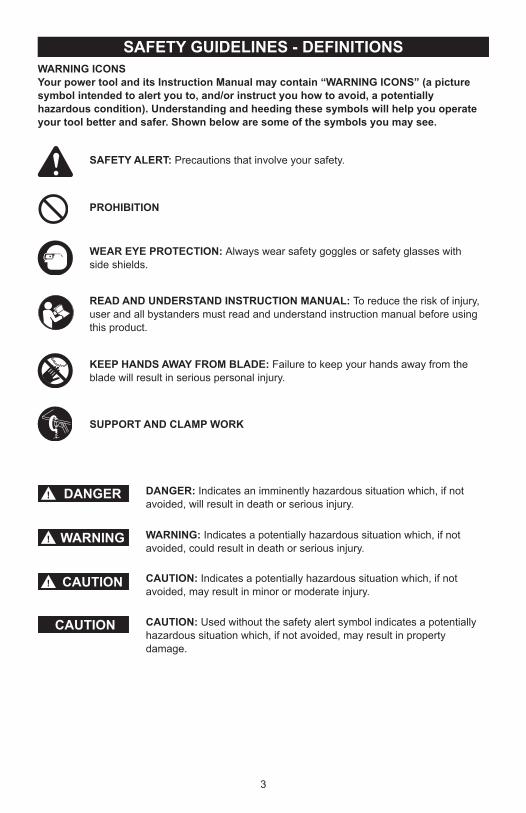
SAFETY GUIDELINES - DEFINITIONSWARNING ICONSYour power tool and its Instruction Manual may contain “WARNING ICONS” (a picture symbol intended to alert you to, and/or instruct you how to avoid, a potentially hazardous condition). Understanding and heeding these symbols will help you operate your tool better and safer. Shown below are some of the symbols you may see.
SAFETY ALERT: Precautions that involve your safety.
PROHIBITION
WEAR EYE PROTECTION: Always wear safety goggles or safety glasses with side shields.
READ AND UNDERSTAND INSTRUCTION MANUAL: To reduce the risk of injury, user and all bystanders must read and understand instruction manual before using this product.
SUPPORT AND CLAMP WORK
KEEP HANDS AWAY FROM BLADE: Failure to keep your hands away from the blade will result in serious personal injury.
DANGER: Indicates an imminently hazardous situation which, if not avoided, will result in death or serious injury.
WARNING: Indicates a potentially hazardous situation which, if not avoided, could result in death or serious injury.
CAUTION: Indicates a potentially hazardous situation which, if not avoided, may result in minor or moderate injury.
CAUTION: Used without the safety alert symbol indicates a potentially hazardous situation which, if not avoided, may result in property damage.
DANGER!
WARNING!
CAUTION!
CAUTION

4
POWER TOOL SAFETYGENERAL SAFETY INSTRUCTIONSBEFORE USING THIS POWER TOOLSafety is a combination of common sense, staying alert and knowing how to use your power tool.
● To avoid mistakes that could cause serious injury, do not plug the tool in until you have read and understood the following.
● Read all instructions before operating product. Failure to follow all instructions listed below may result in electric shock, fire and/or serious injury.
1. READ and become familiar with the entire Instruction Manual. LEARN the tool’s application, limitations and
possible hazards.2. KEEP GUARDS IN PLACE and in working
order.3. REMOVE ADJUSTING KEYS AND
WRENCHES. Form the habit of checking to see that keys and adjusting wrenches are removed from the tool before turning ON.
4. KEEP WORK AREA CLEAN. Cluttered areas and benches invite accidents.
5. DO NOT USE IN DANGEROUS ENVIRONMENTS. Do not use power tools in damp locations, or expose them to rain or snow. Keep work area well lit.
6. KEEP CHILDREN AWAY. All visitors and bystanders should be kept a safe distance from work area.
7. MAKE WORKSHOP CHILD PROOF with padlocks, master switches or by removing starter keys.
8. DO NOT FORCE THE TOOL. It will do the job better and safer at the rate for which it was designed.
9. USE THE RIGHT TOOL. Do not force the tool or an attachment to do a job for which it was not designed.
10. USE PROPER EXTENSION CORDS. Make sure your extension cord is in good condition. When using an extension cord, be sure to use one heavy enough to carry the current your product will draw. An undersized cord will result in a drop in line voltage and in loss of power which will cause the tool to overheat. The table on page 6 shows the correct size to use depending on cord length and nameplate ampere rating. If in doubt, use the next heavier gauge. The smaller the gauge number, the heavier the cord.
11. WEAR PROPER APPAREL. Do not wear loose clothing, gloves, neckties, rings, bracelets or other jewelry which may get caught in moving parts. Nonslip footwear is recommended. Wear protective hair covering to contain long hair.
12. ALWAYS WEAR EYE PROTECTION. Any power tool can throw foreign objects into the eyes
and could cause permanent eye damage. ALWAYS wear Safety Goggles (not glasses) that comply with ANSI Safety standard Z87.1. Everyday eyeglasses have only
WARNING!
impact–resistant lenses. They ARE NOT safety glasses. NOTE: Glasses or goggles not in compliance with ANSI Z87.1 could seriously injure you when they break.
13. WEAR A FACE MASK OR DUST MASK. Sawing operation produces dust.
14. SECURE WORK. Use clamps or a vise to hold work when practical. It is safer than using your hand and it frees both hands to operate the tool.
15. DISCONNECT TOOLS FROM POWER SOURCE before servicing, and when changing accessories such as blades, bits and cutters.
16. REDUCE THE RISK OF UNINTENTIONAL STARTING. Make sure switch is in the OFF position before plugging the tool in.
17. USE RECOMMENDED ACCESSORIES. Consult this Instruction Manual for recommended accessories. The use of improper accessories may cause risk of injury to yourself or others.
18. NEVER STAND ON THE TOOL. Serious injury could occur if the tool is tipped or if the cutting tool is unintentionally contacted.
19. CHECK FOR DAMAGED PARTS. Before further use of the tool, a guard or other part that is damaged should be carefully checked to determine that it will operate properly and perform its intended function – check for alignment of moving parts, binding of moving parts, breakage of parts, mounting and any other conditions that may affect its operation. A guard or other part that is damaged should be properly repaired or replaced.
20. NEVER LEAVE THE TOOL RUNNING UNATTENDED. TURN THE POWER “OFF”. Do not walk away from a running tool until the blade comes to a complete stop and the tool is unplugged from the power source.
21. DO NOT OVERREACH. Keep proper footing and balance at all times.
22. MAINTAIN TOOLS WITH CARE. Keep tools sharp and clean for best and safest performance. Follow instructions for lubricating and changing accessories.
23. DO NOT use power tool in presence of flammable liquids or gases.
24. DO NOT operate the tool if you are under the influence of any drugs, alcohol or medicationn that could affect your ability to use the tool properly.
25. Dust generated from certain materials can be hazardous to your health. Always operate saw in well-ventilated area and provide for proper dust removal.
26.
People with electronic devices, such as pacemakers, should consult their physician(s) before using this product. Operation of electrical equipment in close proximity to a heart pacemaker could cause interference or failure of the pacemaker.
27. WEAR HEARING PROTECTION to reduce the risk of induced
hearing loss.
WARNING!
5
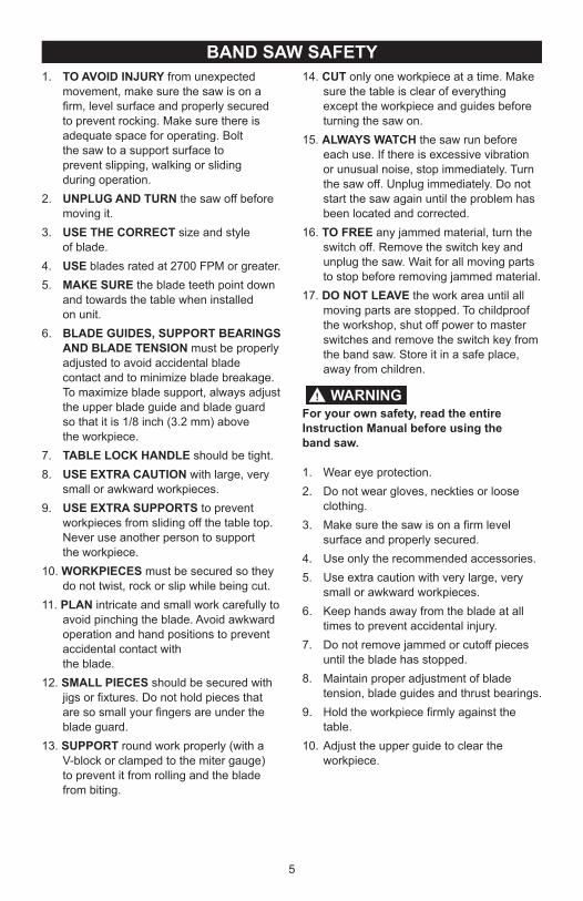
BAND SAW SAFETY1. TO AVOID INJURY from unexpected
movement, make sure the saw is on a firm, level surface and properly secured to prevent rocking. Make sure there is adequate space for operating. Bolt
the saw to a support surface to prevent slipping, walking or sliding during operation.2. UNPLUG AND TURN the saw off before
moving it.3. USE THE CORRECT size and style of blade.4. USE blades rated at 2700 FPM or greater.5. MAKE SURE the blade teeth point down
and towards the table when installed on unit.6. BLADE GUIDES, SUPPORT BEARINGS
AND BLADE TENSION must be properly adjusted to avoid accidental blade contact and to minimize blade breakage. To maximize blade support, always adjust the upper blade guide and blade guard
so that it is 1/8 inch (3.2 mm) above the workpiece.7. TABLE LOCK HANDLE should be tight.8. USE EXTRA CAUTION with large, very
small or awkward workpieces.9. USE EXTRA SUPPORTS to prevent
workpieces from sliding off the table top. Never use another person to support
the workpiece.10. WORKPIECES must be secured so they
do not twist, rock or slip while being cut.11. PLAN intricate and small work carefully to
avoid pinching the blade. Avoid awkward operation and hand positions to prevent accidental contact with
the blade.12. SMALL PIECES should be secured with
jigs or fixtures. Do not hold pieces that are so small your fingers are under the blade guard.
13. SUPPORT round work properly (with a V-block or clamped to the miter gauge)
to prevent it from rolling and the blade from biting.
14. CUT only one workpiece at a time. Make sure the table is clear of everything except the workpiece and guides before turning the saw on.
15. ALWAYS WATCH the saw run before each use. If there is excessive vibration or unusual noise, stop immediately. Turn the saw off. Unplug immediately. Do not start the saw again until the problem has been located and corrected.
16. TO FREE any jammed material, turn the switch off. Remove the switch key and unplug the saw. Wait for all moving parts to stop before removing jammed material.
17. DO NOT LEAVE the work area until all moving parts are stopped. To childproof the workshop, shut off power to master switches and remove the switch key from the band saw. Store it in a safe place, away from children.
For your own safety, read the entire Instruction Manual before using the band saw.
1. Wear eye protection.2. Do not wear gloves, neckties or loose
clothing.3. Make sure the saw is on a firm level
surface and properly secured.4. Use only the recommended accessories.5. Use extra caution with very large, very
small or awkward workpieces.6. Keep hands away from the blade at all
times to prevent accidental injury.7. Do not remove jammed or cutoff pieces
until the blade has stopped.8. Maintain proper adjustment of blade
tension, blade guides and thrust bearings.9. Hold the workpiece firmly against the
table.10. Adjust the upper guide to clear the
workpiece.
WARNING!
6
ELECTRICAL REQUIREMENTS AND SAFETYPOWER SUPPLY AND MOTOR SPECIFICATIONS
To avoid electrical hazards, fire hazards, or damage to the tool, use proper circuit protection. Use a seperate electrical circuit for your tool. Your saw is wired at the factory for 120 V operation. Connect to a 120 V, 10 Amp circuit and use a 10 Amp time delay fuse or circuit breaker. To avoid shock or fire, if power cord is worn, cut, or damaged in any way, have it replaced immediately.
GROUNDING INSTRUCTIONS
This tool must be grounded while in use to protect the operator from electrical shock.
IN THE EVENT OF A MALFUNCTION OR BREAKDOWN, grounding provides a path of least resistance for electric currents and reduces the risk of electric shock. This tool is equipped with an electrical cord that has an equipment-grounding conductor and a grounding plug. The plug must be plugged into a matching receptacle that is properly installed and grounded in accordance with all local codes and ordinances.
DO NOT MODIFY THE PLUG PROVIDED. If it will not fit the receptacle, have the proper receptacle installed by a qualified electrician.
IMPROPER CONNECTION of the equipment grounding conductor can result in risk of electric shock. The conductor with the green insulation (with or without yellow stripes) is the equipment grounding conductor. If repair or replacement of the electrical cord or plug is necessary, do not connect the equipment grounding conductor to a live terminal.
CHECK with a qualified electrician or service person if you do not completely understand the grounding instructions, or if you are not certain the tool is properly grounded.
USE only 3-wire extension cords that have three-pronged grounding plugs with three-pole receptacles that accept the tool’s plug. Repair or replace damaged or worn cords immediately.
Use a separate electrical circuit for your tool. This circuit must not be less than #16 wire and should be protected with a 10 Amp time lag fuse. Before connecting the motor to the power line, make sure the switch is in the off position and the electric current is rated the same as the current stamped on the motor nameplate. Running at a lower voltage will damage the motor.
GUIDELINES FOR EXTENSION CORDS
USE THE PROPER EXTENSION CORD. Make sure your extension cord is in good condition. Use an extension cord heavy enough to carry the
WARNING!
WARNING!
current your product will draw. An undersized cord will cause a drop in line voltage resulting in loss of power, overheating and burning out of the motor. The table below shows the correct size to use depending on cord length and nameplate ampere rating. If in doubt, use the next heavier gauge. The smaller the gauge number, the heavier the cord.
Make sure your extension cord is properly wired and in good condition. Always replace a damaged extension cord or have it repaired by a qualified technician before using it. Protect your extension cords from sharp objects, excessive heat and damp or wet areas.
This tool is for indoor use only. Do not expose to rain or use in damp locations.
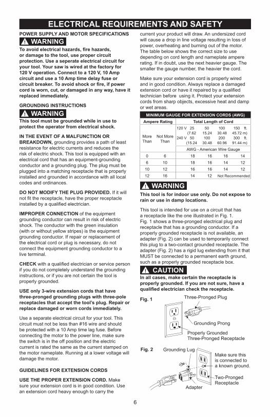
This tool is intended for use on a circuit that has a receptacle like the one illustrated in Fig. 1. Fig. 1 shows a three-pronged electrical plug and receptacle that has a grounding conductor. If a properly grounded receptacle is not available, an adapter (Fig. 2) can be used to temporarily connect this plug to a two-contact grounded receptacle. The adapter (Fig. 2) has a rigid lug extending from it that MUST be connected to a permanent earth ground, such as a properly grounded receptacle box.
In all cases, make certain the receptacle is properly grounded. If you are not sure, have a qualified electrician check the receptacle.
MINIMUM GAUGE FOR EXTENSION CORDS (AWG)Ampere Rating Total Length of Cord
MoreThan
Not More Than
120 V 25 50 100 150 ft. (7.62 15.24 30.48 45.72 m)240 V 50 100 200 300 ft. (15.24 30.48 60.96 91.44 m)
AWG - American Wire Gauge0 6 18 16 16 14 6 10 18 16 14 12 10 12 16 16 14 12 12 16 14 12 Not Recommended
WARNING!
CAUTION!
Fig. 1
Fig. 2
Three-Pronged Plug
Grounding Prong
Properly GroundedThree-Pronged Receptacle
Grounding LugMake sure this is connected to a known ground.
Two-Pronged Receptacle
Adapter
7
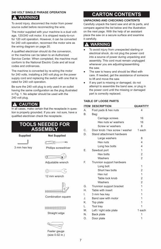
240 VOLT SINGLE PHRASE OPERATION
To avoid injury, disconnect the motor from powersource outlet before reconnecting the wire.
The motor supplied with your machine is a dual volt-age, 120/240 volt motor. It is shipped ready-to-run for 120 volt operation. However, it can be converted for 240 volt operation, reconnect the motor wire as the wiring diagram on page 20.
A qualified electrician should do the conversion, or the machine can be taken to an Authorized Service Center. When completed, the machine must conform to the National Electric Code and all local codes and ordinances.
The machine is converted by re-wiring the motorfor 240 volts, installing a 240 volt plug on the powersupply cord and replacing the switch with one that israted for 240 volt operation.
Be sure the 240 volt plug is only used in an outlet having the same configuration as the plug illustrated in Fig. 1. No adapter should be used with the 240 volt plug.
In all cases, make certain that the receptacle in ques-tion is properly grounded. If you are not sure, have a qualified electrician check the receptacle.
Combination square
Straight edge
Feeler gauge (size 0.02 in.)
Phillips screwdriver
Adjustable wrench
Supplied Not Supplied
3 mm hex key
12 mm wrench
WARNING!
CAUTION!
TOOLS NEEDED FOR ASSEMBLY
UNPACKING AND CHECKING CONTENTSCarefully unpack the band saw and all its parts, and compare against the list below and the illustrationon the next page. With the help of an assistant place the saw on a secure surface and examine it carefully.
● To avoid injury from unexpected starting or electrical shock, do not plug the power cord into a source of power during unpacking and assembly. This cord must remain unplugged whenever you are adjusting/assembling
the saw.● The saw is heavy and should be lifted with
care. If needed, get the assistance of someone to lift and move the saw.
● If any part is missing or damaged, do not attempt to assemble the band saw, or plug in the power cord until the missing or damaged part is correctly replaced.
CARTON CONTENTS
WARNING!
TABLE OF LOOSE PARTS
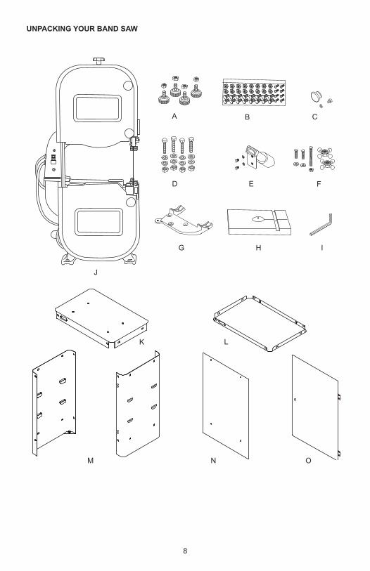
ITEM DESCRIPTION QUANTITYA. Foot pads & hex nuts 4B. Bag:
Carriage screws 16Hex nuts w/ washers 16Screw w/ washers 8
C. Door knob / hex screw / washer 1 eachD. Stand attachment hardware
Large washers 8Hex nuts 4Long hex bolts 4
E. Sawdust port 1Hex bolts 2Washers 2
F. Trunnion support hardwareLong bolt 1Short hex bolts 2Hex nut 1Table lock knob 2Washers 2
G. Trunnion support bracket 1H. Table with insert 1I. 3 mm hex key 1J. Band saw with motor 1K. Top plate 1L. Tool tray 1M. Left / right side plate 1 eachN. Back plate 1O. Door plate 1
8
UNPACKING YOUR BAND SAW
A B C
D E
H
J
F
G
LK
OM N
I
9
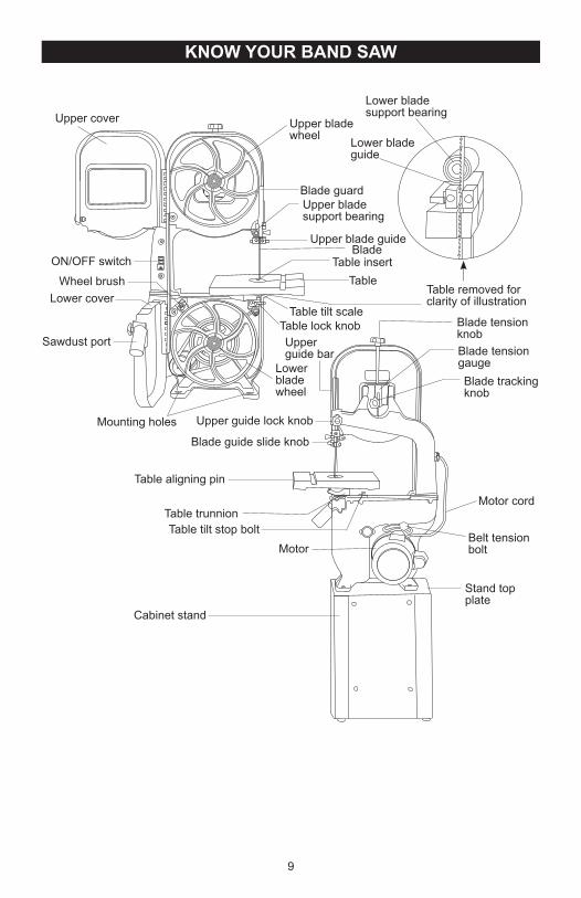
KNOW YOUR BAND SAW
Lower blade support bearing
Lower blade guide
Upper blade wheel
Blade guardUpper blade support bearing
Upper blade guideBlade
Table insertTable
Table removed for clarity of illustration
Blade tension knobBlade tension gaugeBlade tracking knob
Motor cord
Stand top plate
Cabinet stand
Table tilt stop boltMotor
Table trunnion
Table aligning pin
Upper guide bar
Lower blade wheel
Table lock knob
Mounting holes
Sawdust port
Lower coverWheel brush
ON/OFF switch
Upper cover
Upper guide lock knob
Blade guide slide knob
Belt tension bolt
Table tilt scale
10
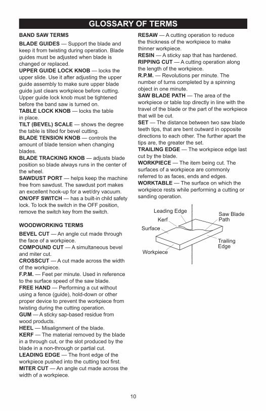
RESAW — A cutting operation to reduce the thickness of the workpiece to make thinner workpiece.RESIN — A sticky sap that has hardened.RIPPING CUT — A cutting operation along the length of the workpiece.R.P.M. — Revolutions per minute. The number of turns completed by a spinning object in one minute. SAW BLADE PATH — The area of the workpiece or table top directly in line with the travel of the blade or the part of the workpiece that will be cut.SET — The distance between two saw blade teeth tips, that are bent outward in opposite directions to each other. The further apart the tips are, the greater the set.TRAILING EDGE — The workpiece edge last cut by the blade.WORKPIECE — The item being cut. The surfaces of a workpiece are commonly referred to as faces, ends and edges.WORKTABLE — The surface on which the workpiece rests while performing a cutting or sanding operation.
GLOSSARY OF TERMSBAND SAW TERMSBLADE GUIDES — Support the blade and keep it from twisting during operation. Blade guides must be adjusted when blade is changed or replaced.UPPER GUIDE LOCK KNOB — locks the upper slide. Use it after adjusting the upper guide assembly to make sure upper blade guide just clears workpiece before cutting. Upper guide lock knob must be tightened before the band saw is turned on.TABLE LOCK KNOB — locks the table in place.TILT (BEVEL) SCALE — shows the degree the table is tilted for bevel cutting.BLADE TENSION KNOB — controls the amount of blade tension when changing blades.BLADE TRACKING KNOB — adjusts blade position so blade always runs in the center of the wheel.SAWDUST PORT — helps keep the machine free from sawdust. The sawdust port makes an excellent hook-up for a wet/dry vacuum.ON/OFF SWITCH — has a built-in child safety lock. To lock the switch in the OFF position, remove the switch key from the switch.
WOODWORKING TERMS BEVEL CUT — An angle cut made through the face of a workpiece.COMPOUND CUT — A simultaneous bevel and miter cut.CROSSCUT — A cut made across the width of the workpiece.F.P.M. — Feet per minute. Used in reference to the surface speed of the saw blade.FREE HAND — Performing a cut without using a fence (guide), hold-down or other proper device to prevent the workpiece from twisting during the cutting operation.GUM — A sticky sap-based residue from wood products.HEEL — Misalignment of the blade.KERF — The material removed by the blade in a through cut, or the slot produced by the blade in a non-through or partial cut.LEADING EDGE — The front edge of the workpiece pushed into the cutting tool first.MITER CUT — An angle cut made across the width of a workpiece.
KerfSurface
Workpiece
Trailing Edge
Saw Blade Path
Leading Edge
11
ASSEMBLY AND ADJUSTMENTSEstimated Assembly Time: 50 - 60 minutes.
For your safety, never connect plug to power source receptacle until all assembly and adjustment steps are complete, and you have read and understood the safety instructions.
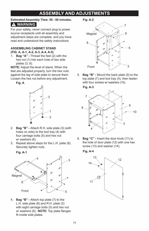
ASSEMBLING CABINET STAND (FIG. A, A-1, A-2, A-3, A-4, A-5)1. Bag “A” - Thread the feet (2) with the
hex nut (1) into each hole of two side plates (3, 8).
NOTE: Adjust the level of stand. When the feet are adjusted properly, turn the hex nuts against the leg of side plate to secure them. Loosen the hex nut before any adjustment.
2. Bag “B” - Attach R.H. side plate (3) (with holes on side) to the tool tray (4) with
four carriage bolts (5) and hex nut w/ washers (6).3. Repeat above steps for the L.H. plate (8).
Securely tighten nuts.
4. Bag “B” - Attach top plate (7) to the L.H. side plate (8) and R.H. plate (3) with eight carriage bolts (5) and hex nut
w/ washers (6). NOTE: Top plate flanges fit inside side plates.
1
2
3
WARNING!
Fig. A
Fig. A-1
34
5
6
Magnet
Front
5. Bag “B” - Mount the back plate (9) to the top plate (7) and tool tray (4), then fasten with four screws w/ washers (10).
6. Bag “C” - Insert the door knob (11) to the hole of door plate (12) with one hex
screw (13) and washer (14).
34
10
9
7
8
13
14
11
12
8
3
5
7
6Magnet
Front
Fig. A-2
Fig. A-3
Fig. A-4
12
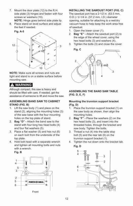
7. Mount the door plate (12) to the R.H. side plate (3) hinges and fasten with four screws w/ washers (10).
NOTE: Hinge goes behind side plate lip.8. Place stand on level surface and adjust
the feet if needed.
NOTE: Make sure all screws and nuts are tight and stand is on a stable surface before mounting saw.
Although compact, this saw is heavy and should be lifted with care. If needed, get the assistance of someone to lift and move the saw.
ASSEMBLING BAND SAW TO CABINET STAND (FIG. B)1. Lift the saw body (1) and place on the stand (2), aligning the mounting holes (3)
of the saw base with the four mounting holes on the top plate of stand.
2. Bag “D” - Attach the band saw to the stand with four long hex head bolts (4) and four flat washers (5).
3. Place a flat washer (5) and hex nut (6) on each bolt from the underside of the top plate. 4. Hold bolt head with a separate wrench
and tighten all mounting bolts and nuts with a wrench.
10
12 3
14
53
256
Front
Fig. A-5
WARNING!
Fig. B
INSTALLING THE SAWDUST PORT (FIG. C)The sawdust port has a 2-1/2 in. (63.5 mm, O.D.) / 2-1/4 in. (57.2 mm, I.D.) diameter opening, suitable for attaching to a wet/dry vacuum hose to help keep the work area free of sawdust.1. Open the lower cover (1).2. Bag “E” - Attach the sawdust port (2) to
the edge of the wheel cover, using the hex head bolts (3) and washers (4).
3. Tighten the bolts (3) and close the cover.
ASSEMBLING THE BAND SAW TABLE (FIG. D, E, F)
Mounting the trunnion support bracket (Fig. D)1. Place the trunnion support bracket (1) on
the saw body as shown, then align the mounting holes.
2. Bag “F” - Place the washers (2) on the hex head bolts (3), and insert into the threaded holes, through the bracket and saw body. Tighten the bolts.
3. Thread a nut (4) into the table stop bolt (5) and the rear tab (6) on the
trunnion support bracket (1).4. Tighten the nut down onto the bracket tab.
3
2
61
54
Fig. C
2
34
1
Fig. D
13
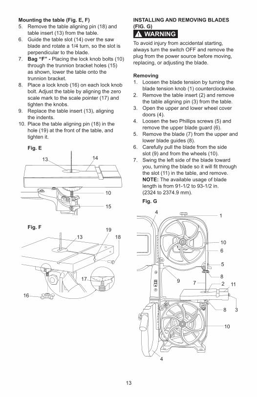
Mounting the table (Fig. E, F)5. Remove the table aligning pin (18) and
table insert (13) from the table.6. Guide the table slot (14) over the saw
blade and rotate a 1/4 turn, so the slot is perpendicular to the blade.
7. Bag “F” - Placing the lock knob bolts (10) through the trunnion bracket holes (15)
as shown, lower the table onto the trunnion bracket.
8. Place a lock knob (16) on each lock knob bolt. Adjust the table by aligning the zero scale mark to the scale pointer (17) and tighten the knobs.
9. Replace the table insert (13), aligning the indents.10. Place the table aligning pin (18) in the
hole (19) at the front of the table, and tighten it.
13 14
10
15
13 18
16
17
19
Fig. E
Fig. F
INSTALLING AND REMOVING BLADES (FIG. G)
To avoid injury from accidental starting, always turn the switch OFF and remove the plug from the power source before moving, replacing, or adjusting the blade.
Removing1. Loosen the blade tension by turning the
blade tension knob (1) counterclockwise.2. Remove the table insert (2) and remove
the table aligning pin (3) from the table.3. Open the upper and lower wheel cover
doors (4).4. Loosen the two Phillips screws (5) and
remove the upper blade guard (6).5. Remove the blade (7) from the upper and
lower blade guides (8).6. Carefully pull the blade from the side slot (9) and from the wheels (10).7. Swing the left side of the blade toward
you, turning the blade so it will fit through the slot (11) in the table, and remove.
NOTE: The available usage of blade length is from 91-1/2 to 93-1/2 in.
(2324 to 2374.9 mm).
1
106
5
82 11
4
9
38
10
4
7
WARNING!
Fig. G
14
Installing1. Make sure the blade tension knob (1) is
turned counterclockwise enough to get blade over pulleys.
2. Remove old blade as explained in “Removing” section.
3. Guide the new blade (7) through the table slot (11). Make sure the blade teeth are pointing forward and down.
NOTE: To avoid lifting the workpiece, the blade teeth must point downward toward the table.
4. Swinging the left side of the blade away and back, place the blade on the upper and lower wheels (10).
5. Place the blade carefully between the upper and lower blade guides (8).
6. Slide the blade into the slot (9) at the left of the wheels, and make sure the blade is positioned at the middle of the wheels.
7. Turning the blade tension knob (1) clockwise, tighten the tension until the blade is tight on the wheels.
8. Replace the upper blade guard (6) and tighten the two Phillips screws (5).
9. Replace the table insert (2) and the table aligning pin (3).
10. Adjust the blade tracking and tension properly (See ADJUSTMENT INSTRUCTIONS section) before operating the band saw.
To avoid injury, the blade tension, tracking, and upper and lower guides and bearings must be properly adjusted before operating the band saw. (See ADJUSTMENT INSTRUCTIONS section)
Before operation always make sure the blade is in center of table insert slot.
ADJUSTMENT INSTRUCTIONS
To avoid injury, turn the switch OFF and unplug the band saw from the power source before making any adjustments.
TABLE ADJUSTMENTS (FIG. H, I)
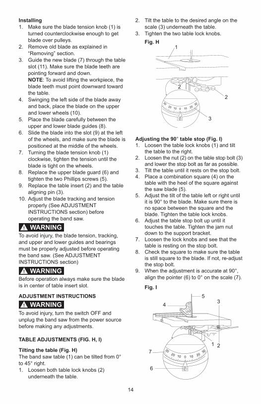
Tilting the table (Fig. H)The band saw table (1) can be tilted from 0° to 45° right.1. Loosen both table lock knobs (2)
underneath the table.
WARNING!
WARNING!
2. Tilt the table to the desired angle on the scale (3) underneath the table.
3. Tighten the two table lock knobs.
Adjusting the 90° table stop (Fig. I)1. Loosen the table lock knobs (1) and tilt
the table to the right.2. Loosen the nut (2) on the table stop bolt (3)
and lower the stop bolt as far as possible.3. Tilt the table until it rests on the stop bolt.4. Place a combination square (4) on the
table with the heel of the square against the saw blade (5).
5. Adjust the tilt of the table left or right until it is 90° to the blade. Make sure there is no space between the square and the blade. Tighten the table lock knobs.
6. Adjust the table stop bolt up until it touches the table. Tighten the jam nut down to the support bracket.
7. Loosen the lock knobs and see that the table is resting on the stop bolt.
8. Check the square to make sure the table is still square to the blade. If not, re-adjust the stop bolt.
9. When the adjustment is accurate at 90°, align the pointer (6) to 0° on the scale (7).
WARNING!
Fig. H
010 1020 20
30 30
2
2
1
3
Fig. I
010 1020 20
30 30
3
7
6
1 2
45
15
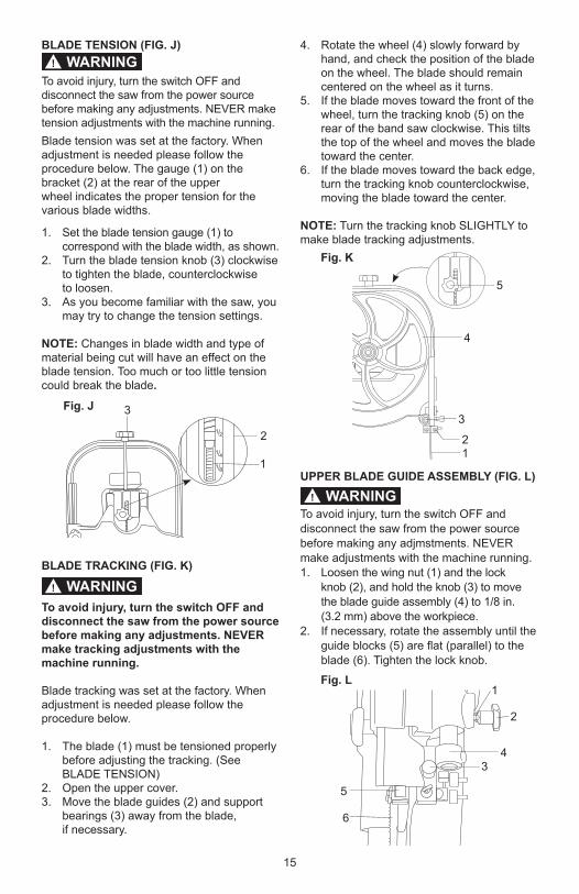
BLADE TENSION (FIG. J)
To avoid injury, turn the switch OFF and disconnect the saw from the power source before making any adjustments. NEVER make tension adjustments with the machine running. Blade tension was set at the factory. When adjustment is needed please follow the procedure below. The gauge (1) on the bracket (2) at the rear of the upperwheel indicates the proper tension for the various blade widths.
1. Set the blade tension gauge (1) to correspond with the blade width, as shown.
2. Turn the blade tension knob (3) clockwise to tighten the blade, counterclockwise
to loosen.3. As you become familiar with the saw, you
may try to change the tension settings.
NOTE: Changes in blade width and type of material being cut will have an effect on the blade tension. Too much or too little tension could break the blade.
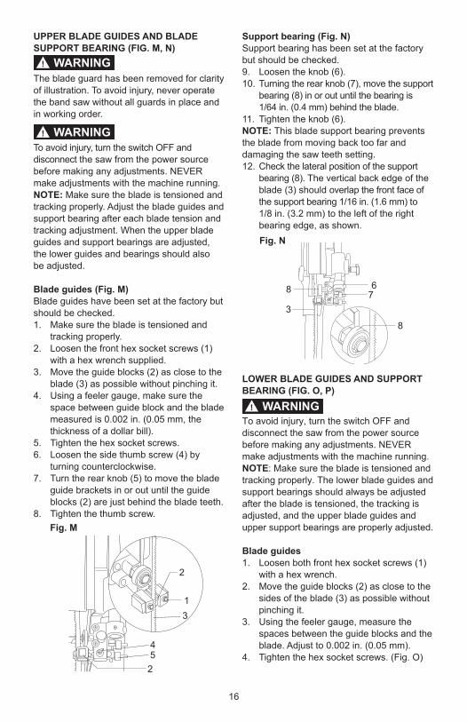
BLADE TRACKING (FIG. K)
To avoid injury, turn the switch OFF and disconnect the saw from the power source before making any adjustments. NEVER make tracking adjustments with the machine running.
Blade tracking was set at the factory. When adjustment is needed please follow the procedure below.
1. The blade (1) must be tensioned properly before adjusting the tracking. (See BLADE TENSION)
2. Open the upper cover.3. Move the blade guides (2) and support
bearings (3) away from the blade, if necessary.
WARNING!
4. Rotate the wheel (4) slowly forward by hand, and check the position of the blade on the wheel. The blade should remain centered on the wheel as it turns.
5. If the blade moves toward the front of the wheel, turn the tracking knob (5) on the rear of the band saw clockwise. This tilts the top of the wheel and moves the blade toward the center.
6. If the blade moves toward the back edge, turn the tracking knob counterclockwise, moving the blade toward the center.
NOTE: Turn the tracking knob SLIGHTLY to make blade tracking adjustments.
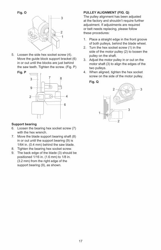
UPPER BLADE GUIDE ASSEMBLY (FIG. L)
To avoid injury, turn the switch OFF and disconnect the saw from the power source before making any adjmstments. NEVER make adjustments with the machine running.1. Loosen the wing nut (1) and the lock knob (2), and hold the knob (3) to move
the blade guide assembly (4) to 1/8 in. (3.2 mm) above the workpiece.2. If necessary, rotate the assembly until the
guide blocks (5) are flat (parallel) to the blade (6). Tighten the lock knob.
WARNING!
Fig. J
1 2
1 4
1 8
2
1
3
Fig. K
5
4
3
21
WARNING!
Fig. L
5
6
4
2
1
3
16
UPPER BLADE GUIDES AND BLADE SUPPORT BEARING (FIG. M, N)
The blade guard has been removed for clarity of illustration. To avoid injury, never operate the band saw without all guards in place and in working order.
To avoid injury, turn the switch OFF and disconnect the saw from the power source before making any adjustments. NEVER make adjustments with the machine running. NOTE: Make sure the blade is tensioned and tracking properly. Adjust the blade guides and support bearing after each blade tension and tracking adjustment. When the upper blade guides and support bearings are adjusted, the lower guides and bearings should also be adjusted.
Blade guides (Fig. M)Blade guides have been set at the factory but should be checked.1. Make sure the blade is tensioned and
tracking properly.2. Loosen the front hex socket screws (1)
with a hex wrench supplied.3. Move the guide blocks (2) as close to the
blade (3) as possible without pinching it.4. Using a feeler gauge, make sure the
space between guide block and the blade measured is 0.002 in. (0.05 mm, the thickness of a dollar bill).
5. Tighten the hex socket screws.6. Loosen the side thumb screw (4) by
turning counterclockwise.7. Turn the rear knob (5) to move the blade
guide brackets in or out until the guide blocks (2) are just behind the blade teeth.
8. Tighten the thumb screw.
Support bearing (Fig. N)Support bearing has been set at the factory but should be checked.9. Loosen the knob (6).10. Turning the rear knob (7), move the support
bearing (8) in or out until the bearing is 1/64 in. (0.4 mm) behind the blade.11. Tighten the knob (6).NOTE: This blade support bearing prevents the blade from moving back too far and damaging the saw teeth setting.12. Check the lateral position of the support
bearing (8). The vertical back edge of the blade (3) should overlap the front face of the support bearing 1/16 in. (1.6 mm) to
1/8 in. (3.2 mm) to the left of the right bearing edge, as shown.
LOWER BLADE GUIDES AND SUPPORT BEARING (FIG. O, P)
To avoid injury, turn the switch OFF and disconnect the saw from the power source before making any adjustments. NEVER make adjustments with the machine running.NOTE: Make sure the blade is tensioned and tracking properly. The lower blade guides and support bearings should always be adjusted after the blade is tensioned, the tracking is adjusted, and the upper blade guides and upper support bearings are properly adjusted.
Blade guides1. Loosen both front hex socket screws (1)
with a hex wrench.2. Move the guide blocks (2) as close to the
sides of the blade (3) as possible without pinching it.
3. Using the feeler gauge, measure the spaces between the guide blocks and the blade. Adjust to 0.002 in. (0.05 mm).
4. Tighten the hex socket screws. (Fig. O)
WARNING!
Fig. M
2
1
25
3
4
Fig. N
8
678
3
WARNING!
WARNING!
17
PULLEY ALIGNMENT (FIG. Q)The pulley alignment has been adjusted at the factory and shouldn’t require further adjustment. If adjustments are required or belt needs replacing, please follow these procedures:
1. Place a straight edge in the front groove of both pulleys, behind the blade wheel.
2. Turn the hex socket screw (1) in the side of the motor pulley (2) to loosen the pulley on the shaft.
3. Adjust the motor pulley in or out on the motor shaft (3) to align the edges of the two pulleys.
4. When aligned, tighten the hex socket screw on the side of the motor pulley.
5. Loosen the side hex socket screw (4). Move the guide block support bracket (6) in or out until the blocks are just behind the saw teeth. Tighten the screw. (Fig. P)
Support bearing6. Loosen the bearing hex socket screw (7)
with the hex wrench.7. Move the blade support bearing shaft (8)
in or out until the support bearing (9) is 1/64 in. (0.4 mm) behind the saw blade.
8. Tighten the bearing hex socket screw. 9. The back edge of the blade (3) should be
positioned 1/16 in. (1.6 mm) to 1/8 in. (3.2 mm) from the right edge of the
support bearing (9), as shown.
12
3
Fig. O
Fig. P
3
9
2
7 8
4
6
Fig. Q
13
2
32
18
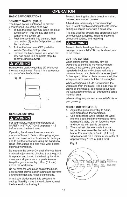
OPERATIONBASIC SAW OPERATIONS
“ON/OFF” SWITCH (FIG. R)The keyed switch is intended to prevent unauthorized use of the band saw.1. To turn the band saw ON insert the black
switch key (1) into the key slot in the center of the switch (2).
2. Push the key firmly into the slot, then push switch (2) to the ON position to start the band saw.
3. To turn the band saw OFF push the switch (2) to the OFF position.
4. Remove the black switch key, when the saw has come to a complete stop, by gently pulling it outward.
Remove the black switch key (1) whenever the saw is not in use. Place it in a safe place and out of reach of children.
GENERAL CUTTING
For your safety, read and understand all SAFETY INSTRUCTIONS on pages 4 - 6 before using the band saw.Operating band saws involves a certain amount of hazard. Before attempting regular work, use scrap lumber to check the settings, and to get the feel of operating the band saw. Read instructions and plan your work before cutting a workpiece.Do not turn the power ON until after you have made all adjustments, checked that the guard is in place, and turned the wheel by hand to make sure all parts work properly. Always keep the guide assembly 1/8 in. (3.2 mm) above the workpiece.Do not force the workpiece against the blade. Light contact permits easier cutting and prevents unwanted friction and heating of the blade.Sharp saw blades need little pressure for cutting. Steadily move the workpiece against the blade without forcing it.
WARNING!
Fig. R
2
1
WARNING!
To avoid twisting the blade do not turn sharp corners; saw around corners.A band saw is basically a “curve-cutting” saw. It is not capable of doing intricate inside cutting as can be done with a scroll saw.It is also used for straight line operations such as crosscutting, ripping, mitering, beveling, compound cutting, and resawing.
To avoid blade breakage, fire or other damage or injury, NEVER use this band saw to cut metals.
CUTTING CURVESWhen cutting curves, carefully turn the workpiece so the blade may follow without twisting. If the curve is so sharp that you repeatedly back up and cut new kerf, use a narrower blade, or a blade with more set (teeth further apart). When a blade has more set, the workpiece turns easier but the cut is rougher.When changing a cut, do not withdraw the workpiece from the blade. The blade may get drawn off the wheels. To change a cut, turn the workpiece and saw out through the scrap material area. When cutting long curves, make relief cuts as you go along.
ClRCLE CUTTING (FIG. S)1. Adjust the guide assembly to 1/8 in. (3.2 mm) above the workpiece.2. Use both hands while feeding the work
into the blade. Hold the workpiece firmly against the table. Do not force the work and operate with gentle pressure.
3. The smallest diameter circle that can be cut is determined by the width of the blade. For example, a 1/4 in. (6.4 mm) wide blade will cut a minimum diameter of approximately 1-1/2 in. (38.1 mm).
WARNING!
Fig. S
1/2 in. D
1/8 in.
1 in. D 1-1/2 in. D 2 in. D 2-1/2 in. D
3/16 in. 1/4 in. 3/8 in. 1/2 in.
MinimumCircle Diameter
Blade Width(3.2 mm) (4.8 mm) (6.4 mm) (9.5 mm) (12.7 mm)
(12.7 mm) (25.4 mm) (38.1 mm) (50.8 mm) (63.5 mm)
19
Common causes of blade breakage:● Poor guide alignment and adjustment.● Forcing or twisting a wide blade around a
short radius.● Feeding too fast.● Dull teeth or not enough set.● Too much blade tension.● Setting top guide assembly too high
above the workpiece.● Lumpy or improperly finished braze or
weld on the blade.● Continuous running of blade when not
cutting.
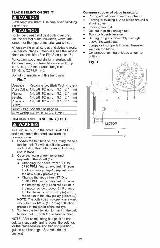
BLADE SELECTION (FIG. T)
Blade teeth are sharp. Use care when handling a saw blade.
For longest wear and best cutting results, use the correct blade thickness, width, and temper for the type of material you will cut.When sawing small curves and delicate work, use narrow blades. Otherwise, use the widest blade as possible. (See Fig. S on page 18)For cutting wood and similar materials with this band saw, purchase blades in width up to 1/2 in. (12.7 mm), and a length of 93-1/2 in. (2374.9 mm). Do not cut metals with this band saw.
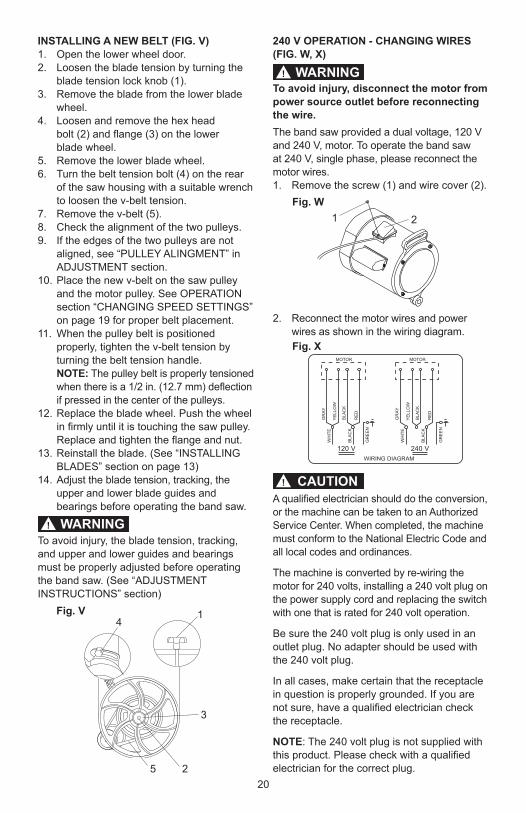
CHANGING SPEED SETTING (FIG. U)
To avoid injury, turn the power switch OFF and disconnect the band saw from the power source.1. Loosen the belt tension by turning the belt
tension bolt (6) with a suitable wrench and rotating the motor counterclockwise until it stops.
2. Open the lower wheel cover and re-position the V-belt (3).
● Changing the speed from 1630 to 2730 FPM: first remove belt (3) from the band saw pulley(4); reposition in the saw pulley groove (1).
● Change the speed from 2730 to 1630 FPM: first remove belt (3) from
the motor pulley (5) and reposition in the motor pulley groove (2). Remove the belt from the saw pulley (4) and reposition in the saw pulley groove (2).
NOTE: The pulley belt is properly tensioned when there is 1/2 in. (12.7 mm) deflection if pressed in the center of the pulleys.
3. Tighten the belt tension by turning the belt tension bolt (6) with the suitable wrench.
NOTE: After re-adjusting belt position and belt tension, verify and re-adjust the settings for the blade tension and tracking position, guides and bearings. (See Adjustment section)
CAUTION!
CAUTION!
Fig. T
Operation Recommended Blade Width (Inches)Cross Cutting 1/4, 3/8, 1/2 in. (6.4 ,9.5, 12.7 mm)Mitering 1/4, 3/8, 1/2 in. (6.4 ,9.5, 12.7 mm) Beveling 1/4, 3/8, 1/2 in. (6.4 ,9.5, 12.7 mm)Compound Cutting
1/4, 3/8, 1/2 in. (6.4 ,9.5, 12.7 mm)
Circle Cutting See chart on page 18Curve Cutting 1/8, 1/4 in. (3.2, 6.4 mm)
WARNING!
45 3
21
4
5
12
MOTOR
6
Fig. U
20
INSTALLING A NEW BELT (FIG. V)1. Open the lower wheel door.2. Loosen the blade tension by turning the
blade tension lock knob (1).3. Remove the blade from the lower blade
wheel.4. Loosen and remove the hex head bolt (2) and flange (3) on the lower blade wheel.5. Remove the lower blade wheel.6. Turn the belt tension bolt (4) on the rear
of the saw housing with a suitable wrench to loosen the v-belt tension.
7. Remove the v-belt (5).8. Check the alignment of the two pulleys.9. If the edges of the two pulleys are not
aligned, see “PULLEY ALINGMENT” in ADJUSTMENT section.
10. Place the new v-belt on the saw pulley and the motor pulley. See OPERATION section “CHANGING SPEED SETTINGS” on page 19 for proper belt placement.
11. When the pulley belt is positioned properly, tighten the v-belt tension by turning the belt tension handle.
NOTE: The pulley belt is properly tensioned when there is a 1/2 in. (12.7 mm) deflection if pressed in the center of the pulleys.
12. Replace the blade wheel. Push the wheel in firmly until it is touching the saw pulley. Replace and tighten the flange and nut.
13. Reinstall the blade. (See “INSTALLING BLADES” section on page 13)
14. Adjust the blade tension, tracking, the upper and lower blade guides and bearings before operating the band saw.
To avoid injury, the blade tension, tracking, and upper and lower guides and bearings must be properly adjusted before operating the band saw. (See “ADJUSTMENT INSTRUCTIONS” section)
WARNING!
Fig. V 14
3
25
240 V OPERATION - CHANGING WIRES (FIG. W, X)
To avoid injury, disconnect the motor from power source outlet before reconnecting the wire.The band saw provided a dual voltage, 120 Vand 240 V, motor. To operate the band saw at 240 V, single phase, please reconnect the motor wires.1. Remove the screw (1) and wire cover (2).
2. Reconnect the motor wires and power wires as shown in the wiring diagram.
A qualified electrician should do the conversion, or the machine can be taken to an Authorized Service Center. When completed, the machine must conform to the National Electric Code and all local codes and ordinances.
The machine is converted by re-wiring the motor for 240 volts, installing a 240 volt plug on the power supply cord and replacing the switch with one that is rated for 240 volt operation.
Be sure the 240 volt plug is only used in an outlet plug. No adapter should be used with the 240 volt plug.
In all cases, make certain that the receptacle in question is properly grounded. If you are not sure, have a qualified electrician check the receptacle.
NOTE: The 240 volt plug is not supplied with this product. Please check with a qualified electrician for the correct plug.
WARNING!
CAUTION!
Fig. W
Fig. X
21
WIRING DIAGRAM
120 V
MOTOR
WH
ITE
YE
LLO
W
GR
AY
RE
DB
LAC
K
GR
EE
N
BLAC
K
WH
ITE
YE
LLO
W
GR
AY
RE
DB
LAC
K
GR
EE
N
BLAC
K
240 V
MOTOR
21
MAINTENANCEGENERAL MAINTENANCE
For your own safety, turn switch OFF and remove the plug from power source receptacle before maintaining, cleaning,adjusting, or lubricating your band saw.
To avoid fire or toxic reaction, never use gasoline, naphtha, acetone, lacquer thinner or similar highly volatile solvents to clean the band saw.
To avoid eye injury from blowing debris, wear safety goggles when blowing out sawdust.
MAINTENANCEUse only mild soap and damp cloth to clean the tool. Never let any liquid get inside the tool; never immerse any part of the tool into a liquid.
BAND SAWSawdust will accumulate under the table and base. This could cause difficulty in the movement of the table when setting up a band saw cut. Frequently blow out or vacuum up the sawdust. Keep your band saw clean. Remove the sawdust from the inside. Vacuum or blow out frequently.
Do not allow debris to build up on the table, the guides, or the support bearings. Clean them with gum and pitch remover.NOTE: Do not immerse the support bearings in the gum and pitch remover. Apply a thin coat of paste wax on the table so that the wood slides easily while cutting.
BLADE WHEEL TIRESPitch and sawdust that build up on the tires should be removed with a stiff brush or scraped off with a piece of wood.NOTE: To avoid damaging the tires do not use a sharp knife or any kind of solvent.
When the tires become worn, they should be replaced. When replacing the tires, stretch them around the wheels but do not glue them on.
MOTORFrequently blow or vacuum out any sawdust from the motor. Follow lubrication instruction on the motor label.
To avoid electrocution or fire, immediately replace a worn, cut or damaged power cord.
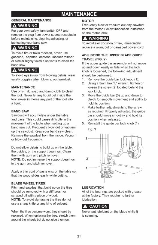
ADJUSTING THE UPPER BLADE GUIDE TRAVEL (FIG. Y)If the upper guide bar assembly will not move up and down easily or falls when the lock knob is loosened, the following adjustment should be performed.1. Remove the guide bar lock knob (1).2. Using a 5mm hex “L” wrench, tighten or
loosen the screw (2) located behind the lock knob.
3. Move the guide bar (3) up and down to check for smooth movement and ability to hold its position.
4. Make further adjustments to the screw as required. Properly adjusted, the guide bar should move smoothly and hold its position when released.
5. Reinstall the guide bar lock knob (1).
LUBRICATIONAll of the bearings are packed with grease at the factory. They require no further lubrication.
Never put lubricant on the blade while it is spinning.
WARNING!
WARNING!
WARNING!
WARNING!
Fig. Y
3
2
1
CAUTION!
22
TROUBLESHOOTING GUIDE
To avoid injury from an accidental start, turn the switch OFF and always remove the plug from the power source before making any adjustments.
REPLACEMENT PARTSUse only identical replacement parts. For a parts list or to order parts, visit our service website at www.portercable.com. You can also order parts from your nearest Porter-Cable Factory Service Center or Porter-Cable Authorized Warranty Service Center. Or, you can call our Customer Care Center at (888) 609-9779.
SERVICE AND REPAIRSAll quality tools will eventually require servicing and/or replacement of parts. For information about Porter-Cable, its factory service centers or authorized warranty service centers, visit our website at www.portercable.com or call our Customer Care Center at (888) 609-9779. All repairs made by our service centers are fully guaranteed against defective material and workmanship. We cannot guarantee repairs made or attempted by others.You can also write to us for information at Power Tool Specialists, Inc. 684 Huey Road, Rock Hill, SC 29730, (888) 609-9779 - Attention: Product Service. Be sure to include all of the information shown on the nameplate of your tool (model number, type, serial number, etc.).
GENERAL
WARNING!
PROBLEM PROBLEM CAUSE SUGGESTED CORRECTIVE ACTIONBlade does not run in the center of upper wheel.
1. Not tracking properly.
2. Defective blade.
1. Adjust tracking. See ASSEMBLY AND ADJUSTMENTS section - "BLADE TRACKING."
2. Replace blade.Band saw slows down when cutting.
1. Belt too loose.
2. Cutting too small a radius.
3. Dull blade.4. Overloading motor.
1. Adjust belt tension. See ASSEMBLY AND ADJUSTMENTS section - "BLADE TENSION."
2. Stop feeding, back up the material slightly, until band saw speeds up.
3. Replace blade.4. Slow down, trying to cut too fast.
See "MOTOR TROUBLESHOOTING GUIDE."
Blades breaking. 1. Too much tension on the blade.
2. Kink in the blade caused by cutting too small a radius or turning the material too fast when cutting.
1. Adjust belt tension. See ASSEMBLY AND ADJUSTMENTS section - "BLADE TENSION."
2. Use correct cutting technique. See OPERATION section section "GENERAL CUTTING."
Blade dulls too quickly.
1. Blade guides set too close to the teeth.
2. Cutting incorrect material.
1. Adjust upper and lower blade guides.
2. See OPERATION section - "BLADE SECTION."
Band saw vibrates.
1. Too much tension on motor belt. 1. Adjust tracking. See ASSEMBLY AND ADJUSTMENTS section - "INSTALL THE BELT."

23
PROBLEM PROBLEM CAUSE SUGGESTED CORRECTIVE ACTIONNoisy operation. 1. Incorrect belt tension.
2. Loose motor pulley.
3. Loose pulley cover.
1. Adjust tension. See ASSEMBLY AND ADJUSTMENTS section - "INSTALL
THE BELT."2. Readjust and tighten motor pulley set
screw.3. Readjust and tighten pulley cover
mounting screws.Motor will not start.
1. Not plugged into power outlet.2. Switch and key not in ON
position.3. Motor cord cut or abraded.
4. Plug on cord is faulty.5. Fuse on circuit breaks open.6. Faulty motor.
1. Plug it into the power outlet.2. Insert key and turn the switch ON.
3. Re-set; may be too many machines on line.4. Contact Porter-Cable Service Center
or Authorized Service Station for repair or replacement.
Motor will not start and fuse or circuit breaker opens.
1. Too many electrical machines.2. Incorrect fuse.
3. Wheels do not rotate.
4. Undersized extension cord.
5. Short circuit.
1. Turn off other machines and try again.2. Try time delay fuse, or go to circuit with
higher rated fuse or circuit breaker.3. Unplug and turn wheels by hand,
move obstruction.4. Use correct size extension cord, see
page 6.5. Cord, plug, or motor need repair.
Contact Porter-Cable Service Center or Authorized Service Station for repair.
Motor fails to develop full power.
1. Low line voltage.2. Faulty motor or capacitor.
1. Check power line for proper voltage.2. Contact Porter-Cable Service Center
or Authorized Service Station for repair.
Motor overheats. 1. Overload on motor.
2. Poor ventilation of motor.
3. Capacitor failure.
1. Reduce load to motor, feed work slower into blade.
2. Unplug and clean out around motor. Provide better air circulation.
3. Contact Porter-Cable Service Center or Authorized Service Station for repair.
Motor stalls or slows.
1. Motor overload.
2. Low line voltage.3. Loose wire connections.4. Faulty motor.
1. Reduce load to motor, feed work slower into blade.
2. Check power line for proper voltage.3. Contact Porter-Cable Service Center or
Authorized Service Station for repair. Frequent fuse or circuit breaker failure.
1. Motor overload.
2. Overload of electrical circuit.
3. Incorrect fuse or circuit breaker.
1. Reduce load to motor, feed work slower into blade.
2. Too many electrical appliances on same circuit.
3. Have electrician upgrade service to outlet.
MOTOR
For assistance with your product, visit our website at www.portercable.com for a list of service centers, or call the Porter-Cable Customer Care Center at (888) 609-9779.

24
ACCESSORIES AND ATTACHMENTSACCESSORIES
Since accessories, other than those offered by Porter-Cable, have not been tested with this product, use of such accessories with this tool could be hazardous. To reduce the risk of injury, only Porter-Cable recommended accessories should be used with this product.
A complete line of accessories is available from your Porter-Cable Factory Service Center or a Porter-Cable Authorized Warranty Service Center. Please visit our Web Site www.portercable.com for a catalog or for the name of your nearest supplier.
Do not use any accessory unless you have completely read the Instruction Manual for that accessory.
WARNING! WARNING!
X0JX RISER BLOCK KITX3ZW MITER GAUGEX4CT RIP FENCE ASSEMBLY

25
PARTS LIST
I.D. Description Size Q’ty I.D. Description Size Q’ty I.D. Description Size Q’ty
X1RS ADJUSTING KNOB ASSEMBLY 1 X262 HEX. SCREW 3/4*2-1/2 1 X40G FRAME ARM COVER, LOWER 1
X1V7 SPRING WASHER 5/16 16 X263 HEX. SCREW 1/4*3/4 2 X40H FRAME ARM COVER, UPPER 1
X1VV SCREW (CROSS HEAD) W/I WASHER 3/16*3/8 11 X264 PULLEY 3 IN. Ø50-Ø76 1 X40J LOWER WHEEL 1
X1W2 CROSS HEAD SCREW 3/16*1/4 3 X26C SPRING PIN 3*30L 1 X40K UPPER WHEEL 1
X1ZU STEEL BALL 1/4 1 X26L STAR KNOB M10 2 X40M LOWER DOOR 1
X21C HEX. FIXTURE BOLT 3/8 3 X26N HINGE UPPER 1 X40N UPPER DOOR 1
X21D CLIP HEAD 3 X26T KNOB 3/8 3 X40P UPPER COVER, INNER 1
X21F BRUSH HOLDER 1 X2D7 SCREW (CROSS HEAD) W/I WASHER 3/16*1/4 12 X40Q TRUNNION BRACKET 1
X21G STEEL PIN 2 X2D8 TABLE PIN 1 X40T PULLEY 7 IN. 1
X21H HEX. FIXTURE BOLT 2 X2DR HEX. SCREW 5/16*3” 1 X40V COMPLETED MOTOR W/CORD 1
X21K UPPER WHEEL SHAFT HINGE 1 X2JS CROSS HEAD SCREW M4*10L 1 X45M INSTRUCTION MANUAL 1
X21L SLIDING BKT. 1 X2NM BALL BEARING 2 X4AV FLAT WASHER 1/4*13 6
X21P PIN 1/4*16 4 X2PN PLASTIC BRUSH 1 X4AU SPRING PIN Ø6*20 1
X21Q PRESS SPRING 1 X2QG NYLON NUT 1/2 1 X56Z SCALE OF BLADE GUARD 1
X21R ADJUSTING SPRING 1 X2S2 SPRING WASHER 1/4 6 X570 WARNING LABEL 1
X21S ADJUSTING KNOB OF UPPER WHEEL 5/16*2L 1 X2SU PLATE 2 X571 WARNING LABEL 1
X21U STAR KNOB 5/16*1-1/4 1 X2U7 FLAT KEY 5*5*30 1 X574 NAMPLATE 1
X21Z TOOTH WASHER 5mm 2 X309 BALL BEARING 2 X575 TABLE INSERT 1
X221 FLAT WASHER 5/16*23 2 X348 STRAIN RELIEF BUSHING 2 X576 DUST COLLECTION HOSE 1
X224 FLAT WASHER 3/8*19 3 X39J RING 2 X577 HEX. BOLT 3/8*1-3/4 1
X225 FLAT WASHER 1/4*16 4 X3ZA SPRING WAHSER 3/16 3 X578 POWER CORD W/INSERT PLUG 1
X227 SPRING WASHER 3/4 1 X3ZB KNOB M6*18L 1 X579 BLADE GUARD, LOWER 1
X228 SQUARE NUT 3/8 1 X3ZF MOTOR LABEL 1 X57A GUIDE SUPPORT BRACKET BLADE GUARD 1
X229 BUTTERFLY NUT 5/16 1 X3ZH SHAFT OF LOWER WHEEL 1 X57B GUIDE POST (V TYPE) 243 MM 1
X22B HEX. NUT 3/4 1 X3ZJ SHAFT OF UPPER WHEEL 1 X57C UPPER ARM 1
X22C SET SCREW 5/16*5/16 1 X3ZL GUARD 1 X57D BASE 1
X22F SET SCREW M6*16L 2 X3ZM FLAT WASHER FOR LOWER WHEEL 1 X57E TABLE 1
X22H CROSS HEAD SCREW 3/16*3/8 2 X3ZN BEARING SHAFT 2
X22K CROSS HEAD SCREW 3/16*3/8 9 X3ZP BLADE GUIDE BLOCK 4 MOTOR PARTS
X22S BEARING COVER 1 X3ZQ Y TYPE GUIDE ACCESSORY 2 X1V8 SPRING WASHER 5 MM 2
X235 TRUNNION CLAMP SHOE 2 X3ZR LOWER GUIDE HOLDER 1 X21Z TOOTH WAHSER 5 MM 1
X238 TRUNNION 2 X3ZS POST SEAT (DOUBLE TEETH) 1 X23R SCREW (CROSS HEAD) W/I WASHER 3/16*1/4 1
X23A SCALE 1 X3ZT CUTTING BLADE 93-1/2*3/8 1 X25X COPPER WAHSER 1
X23B HINGE LOWER 1 X3ZV WHEEL PROTECTOR 2 X2D7 SCREW (CROSS HEAD) W/I WASHER 3/16*1/4 4
X23D POINTER 1 X3ZZ C RING 2 X348 STRAIN RELIEF BUSHING 1
X23F SPRING PIN Ø3*10 1 X400 RING 1 X349 TERMINAL 2
X23G FLAT WASHER 5/16*18 12 X401 FLAT KEY 5*5*60 2 X40Y CROSS HEAD SCREW 3/16*3/16 2
X23J HEX. NUT 5/16 5 X402 FLAT WASHER 3/8*16 1 X411 CAPACITOR COAST 1
X23K HEX. NUT 3/16 5 X403 FLAT WASHER 3/8*25 1 X417 MOTOR WIRE 1
X23L HEX. NUT 1/2 1 X404 FLAT WASHER 1/2*28 1 X418 CAPACITOR 1
X23M HEX. SCREW 5/16*1-1/4 6 X405 MICRO ADJUSTING NUT M6 2 X41C CAPACITOR COVER 1
X23Q HEX. SCREW M10*50L 2 X406 NUT 3/8 1 X41D WIRE COVER, LOWER 1
X23R CROSS HEAD SCREW W/I WASHER 3/16*1/4 2 X407 SECTOR SCREW M6*10L 1 X41E WIRE COVER, UPPER 1
X240 HEX. WRENCH 3 MM 1 X408 SET SCREW M6*45L 2
X241 HEX. SCREW 1/4*1/4 2 X409 SCREW (HEADLESS) M6*10L 7 HARDWARE BAG
X243 SPRING CLIPPER 3 X40A HEX. SCREW 1/4*5/8 7 X4AW STAND ATTACHMENT HARDWARE BAG 1
X244 V-BELT 1 X40B HEX. SCREW 1/2*2” 1 X2DJ SAWDUST PORT HARDWARE BAG 1
X25X COPPER WASHER 2 X40C SAFETY SWITCH 1 X2DH TRUNNION SUPPORT HARDWARE BAG 1
X25Y WASHER 3/16-14 4 X40D BALL BEARING 2
X25Z FLAT WASHER 3/4 2 X40F GUARD STRONGER 1
14 IN. (355 MM) BAND SAW PARTS LIST FOR BAND SAW

26
14 IN. (355 MM) BAND SAW SCHEMATIC FOR BAND SAW
X1RS
X21L
X21S
X229
X21Q
X228
X26C
X21G
2
X21K
X3ZJ
X21U
X22C
X21R
X1ZU
X57C
X57BX4
AU
X406
X40P
X224
X21C
X21D
X3ZA
X1W
2
X224
X21C
X21D
X3ZA
X1W
2
X240
X40N
X571
X26T
3
X574
X2D
8
X23F
X57E
X575
X23L
X23K
12
X1V7
8
X26N
X2D
7 12
X576
X570
X40M
X23B
X22K
4
X1V7
8
X243
3
X225
2X2
412
X40A
X3ZM
2X3
ZV
X40J
X244
X40T
X40G
X1VV
2
2
2
X22F
X264
X2Q
G
X309
X3ZH
X401
X2PN
X1VV
X21F
X22H
2
2X2
21X3
ZL
X2JS
X23G
8
X23M
4
X21H
X402
X23G
X23J
4 4
X40V
X40B
X404
X2U
7
X40C
X40F
X40H
X1VV
2
X403
X577
X3ZZ
X22S
X22K
2
X3ZF
X21P
4
X227
X22B
X57D
X21C
X224
X578
X348
2
X2SU
X1VV
4
X262X3
ZSX2
1Z2X2
5X2
X23R
2
X579
X25Z
2
X263
2
X225
2
X3ZR
X407
X409
4
X3ZQ
2
X409
2
X3ZN
2 X40D
2
X3ZP
4
X39J
2
X23Q
X23Q
X235
X235
X238
X238
X23A
X23D X1
V8X2
2K
X40Q
X26L
2
X23M
X23M
X2D
R X23J
X23G
X4AV
6
66X2
S2X4
0A
X405
2 X408
2X4
09X3
ZB
X57A
X25Y
2
2
X22KX5
6Z
X3ZT
X40K
X21H
X402
X25Y
2 X1VV
2
X2N
M2
X400
2M
AN
UA
L
X45M
INST
RCTI
ON
X23
M
X23
J
X4A
W
X2D
H
X23
G
D. H
ard
war
e B
ag
4 8 4
X24
1
X23
9X
225
2
2
22
2
E. H
ard
war
e B
ag
F. H
ard
war
e B
ag
X23
MX
26L
X2D
R
X23
JX
23G
X2D
J
MAN
UAL
MO
TOR
PAR
TS
X349
`X3
48
X418
X23R
X411
X21ZX2
5XX4
1D
X417
X2D
7
X41E
X2D
7
X2D
7X4
1C
X1V8
X40Y
2
2
2
2
X23G
X21D X3
ZA X1W
2
27
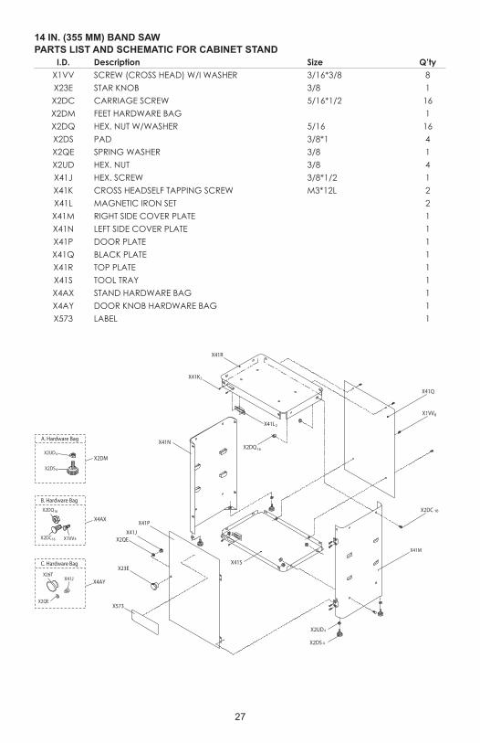
I.D. Description Size Q’tyX1VV SCREW (CROSS HEAD) W/I WASHER 3/16*3/8 8X23E STAR KNOB 3/8 1X2DC CARRIAGE SCREW 5/16*1/2 16X2DM FEET HARDWARE BAG 1X2DQ HEX. NUT W/WASHER 5/16 16X2DS PAD 3/8*1 4X2QE SPRING WASHER 3/8 1X2UD HEX. NUT 3/8 4X41J HEX. SCREW 3/8*1/2 1X41K CROSS HEADSELF TAPPING SCREW M3*12L 2X41L MAGNETIC IRON SET 2X41M RIGHT SIDE COVER PLATE 1X41N LEFT SIDE COVER PLATE 1X41P DOOR PLATE 1X41Q BLACK PLATE 1X41R TOP PLATE 1X41S TOOL TRAY 1X4AX STAND HARDWARE BAG 1X4AY DOOR KNOB HARDWARE BAG 1X573 LABEL 1
14 IN. (355 MM) BAND SAWPARTS LIST AND SCHEMATIC FOR CABINET STAND
A. Hardware Bag
B. Hardware Bag
C. Hardware Bag
X2UDX2DM
X4AX
X4AY
X2DS
4
4
X2DC X1VV
X2DQ16
16 8
X26T
X2QE
X41J
X41M
X2DC 16
X1VV8
X41Q
X2DQ16
X41L2
X41N
X41S
X41P
X41JX2QE
X23E
X573
X2UD4
4X2DS
X41R
X41K2

28
THREE YEAR LIMITED WARRANTY
PORTER-CABLE will repair, without charge, any defects due to faulty materials or workmanship for three years from the date of purchase. This warranty does not cover part failure due to normal wear or tool abuse. For further detail of warranty coverage and warranty repair information, visit www.portercable.com or call (888) 609-9779. This warranty does not apply to accessories or damage caused where repairs have been made or attempted by others. This warranty gives you specific legal rights and you may have other rights which vary in certain states or provinces.
In addition to the warranty, PORTER-CABLE tools are covered by our:
1 YEAR FREE SERVICE: PORTER-CABLE will maintain the tool and replace worn parts caused by normal use, for free, any time during the first year after purchase.
90 DAYS MONEY BACK GUARANTEE: If you are not completely satisfied with the performance of your PORTER-CABLE Power Tool for any reason, you can return it within 90 days from the date of purchase with a receipt for a full refund – no questions asked.
LATIN AMERICA: This warranty does not apply to products sold in Latin America. For products sold in Latin America, see country specific warranty information contained in the packaging, call the local company or see website for warranty information.
To register your tool for warranty service visit our website at www.portercable.com.
WARNING LABEL REPLACEMENTIf your warning labels become illegible or are missing, call (888) 609-9779 for a free replacement.
The following are PORTER-CABLE trademarks for one or more power tools and accessories: a gray and black color scheme; a “four point star” design; and three contrasting/outlined longitudinal stripes. The following are also trademarks for one or more Porter-Cable and Delta products: 2 BY 4®, 890TM, Air America®, AIRBOSSTM, Auto-Set®, B.O.S.S.®, Bammer®, Biesemeyer®, Builders Saw®, Charge Air®, Charge Air Pro®, CONTRACTOR SUPERDUTY®, Contractor’s Saw®, Delta®, DELTA®, Delta Industrial®. DELTA MACHINERY & DESIGNTM, Delta Shopmaster and Design®, Delta X5®, Deltacraft®, DELTAGRAM®, Do It. Feel it.®, DUAL LASERLOC AND DESIGN®, EASY AIR®, EASY AIR TO GOTM, ENDURADIAMOND®, Ex-Cell®, Front Bevel Lock®, Get Yours While the Sun Shines®, Grip to Fit®, GRIPVACTM, GTF®, HICKORY WOODWORKING®, Homecraft®, HP FRAMER HIGH PRESSURE®, IMPACT SERIESTM, Innovation That Works®, Jet-Lock®, Job Boss®, Kickstand®, LASERLOC®, LONG-LASTING WORK LIFE®, MAX FORCETM, MAX LIFE®, Micro-Set®, Midi-Lathe®, Monsoon®, MONSTER-CARBIDETM, Network®, OLDHAM®, Omnijig®, PC EDGE®, Performance CrewTM, Performance Gear®, Pocket Cutter®, Porta-Band®, Porta-Plane®, Porter-Cable®, Porter-Cable Professional Power Tools®, Powerback®, POZI-STOPTM, Pressure Wave®, PRO 4000®, Proair®, Quicksand and Design®, Quickset II®, QUIET DRIVE TECHNOLOGYTM, QUIET DRIVE TECHNOLOGY AND DESIGNTM, Quick-Change®, QUIK-TILT®, RAPID-RELEASETM, RAZOR®, Redefining Performance®, Riptide®, Safe Guard II®, Sand Trap and Design®, Sanding Center®, Saw Boss®, Shop Boss®, Sidekick®, Site Boss®, Speed-Bloc®, Speedmatic®, Stair Ease®, Steel Driver Series®, SUPERDUTY®, T4 & DESIGN®, THE AMERICAN WOODSHOP®, THE PROFESSIONAL EDGE®, Thin-Line®, Tiger Saw®, TIGERCLAW®, TIGERCLAW AND DESIGN®, Torq-Buster®, TRU-MATCH®, T-Square®, Twinlaser®, Unifence®, Uniguard®, UNIRIP®, UNISAW®, UNITED STATES SAW®, Veri-Set®, Versa-Feeder®, VIPER®, VTTM, VT RAZORTM, Water Driver®, WATER VROOM®, Waveform®, Whisper Series®, X5®, YOUR ACHIEVEMENT. OUR TOOLS.®, Trademarks noted with ® are registered in the United States Patent and Trademark Office and may also be registered in other countries. Other trademarks may apply.
PORTER-CABLE and the PORTER-CABLE logo are registered trademarks of PORTER-CABLE and are used under license. All rights reserved.
Power Tool Specialists, Inc. 684 Huey Road, Rock Hill, SC 29730
(888) 609-9779www.portercable.com
WARRANTY