1413.06.08 cam followers - bearing stocks followers rbc division 800.390.3300 a wide array of...
TRANSCRIPT

Cam Followers
RBC Division www.rbcbearings.com800.390.3300
A wide array of products including patented RBC Roller® cylindrical rollerand needle roller cam followers - both stud and yoke styles.
RBC Roller®, HexLube®, CamCentric®

2
RBC Bearings Incorporated (RBC Bearings, RBC) has had a long tradi-tion of innovation, commitment, and quality since the company wasfounded in 1919. Today, RBC Bearings has grown into a world-classmanufacturer of standard and custom-engineered bearings and relatedproducts, with a product focus on research, testing, and development ofthe best product for specific applications.
What We Manufacture
RBC Bearings, with facilities throughout North America and Europe,provides bearings and precision products for applications in the con-struction, mining, material handling, transportation and off-highwayequipment, robotics and automation, farming, machine tool, and semi-conductor equipment industries. Through RBC Aerospace Bearings,the company is a major manufacturer of highly-engineered bearings andprecision products for military, defense, and commercial aerospaceapplications.
RBC's high-quality bearings include:
• Heavy Duty Needle Roller Bearings - Pitchlign® caged heavy dutyneedle roller bearings, inner rings, type TJ TandemRoller® bearings forlong life.
• Spherical Plain Bearings - Radial, angular, contact, high misalign-ment, extended inner ring, DuraLube™ maintenance-free sphericalplain bearings, QuadLube® long life bearings, ImpactTuff® case carbur-ized bearings, ShimPack® double-acting angular contact bearings,CrossLube® lubrication groove systems, and SpreadLock® Seal.
• Cam Followers and Yoke Rollers - Standard stud, heavy stud, yoketype, caged roller followers, RBC Roller® long life cam followers,HexLube® universal cam followers, airframe track rollers. Mastguiderollers and carriage rollers, chain sheaves (for leaf chain), toothlesssprockets (for roller chain), and heavy-duty roller bearing construction.
• Rod Ends - Commercial and aerospace, precision, Mil-Spec series,self-lubricating, inch and metric. Heim®, Unibal®, and Spherco™brands.
• Self-Lubricating Bearings - Radial, thrust, rod ends, spherical plainbearings, high temperature, high loads, inch and metric. Fiberglide®
brand.
• Thin Section Ball Bearings - Standard cross sections to one inch.Sizes to 40 inches. Stainless steel and other materials available. Sealsavailable on all sizes and standard cross sections.
• Airframe Control Bearings - Ball bearing types, self-lubricatingtypes, needle rollers, track rollers.
• Ground, Semiground, and Unground Ball Bearings - Full comple-ment, utilizes design and burnished races for higher loads, long life, andsmooth operation.
• Dowel Pins, Loose Needle Rollers, Shafts
• Tapered Roller and Tapered Thrust Bearings - Case-hardened andthrough-hardened in a variety of sizes, used in Class 8 heavy truck andtrailer wheel bearings, final drive transmissions and gear boxes.
• Custom Designed Bearings - RBC produces a wide range of custombearings in various materials for specific applications.
RBC Cam FollowersRBC produces an extensive cam follower product line from 1/2 inchroller O.D. to 10 inch roller O.D. Standard stud, heavy stud, and yoketypes are made in sealed and unsealed configurations. The caged SRFroller is popular in applications requiring oil bath lubrication, highspeed, or in applications greased for life.
RBC heavy duty roller type mast guide and chain sheaves are used in avariety of lifting mechanisms - lift trucks, auto lift and specialty lift.
RBC produces metric cam followers where volume permits. ContactRBC for availability.
Type NBC, NBF, and NBL aircraft track rollers are also listed in thiscatalog. These bearings are used in aircraft wing flaps and slats, asdoor latches, landing gear door hinges, and in a variety of industrialapplications requiring plated bearings.
Unique cam follower products offered include:
• RBC Roller® - A long life cam follower, the RBC Roller (Patent No.5531137) has been developed for use in applications that cannot becompromised. The RBC Roller offers an average 400% life improve-ment over needle bearing cam follower designs and can substantiallyreduce operating costs.
• HexLube® - RBC stud type cam followers have a new HexLube fea-ture and come equipped with a grease fitting installed in the rollerend, thus permitting relubrication. HexLube can reduce inventory by50% by consolidating other varieties of cam followers and inter-changing them with HexLube.
• CamCentric® - The RBC CamCentric cam follower allows the userto adjust the height at which the cam follower rides along the track.
How We Can Serve You RBC has implemented a total quality control system that uses statisticalquality control at all facilities, and manufactures in high volume to ajust-in-time program.
To serve the ongoing needs of customers, RBC has a network of over1,600 distributors and sales engineers throughout the US, Europe, andSouth America, with authorized agents worldwide. For assistance withyour bearing application, contact:
Customer Service - 800.390.3300
WarrantyRBC products are warranted for material and workmanship for a periodnot to exceed 90 days from shipment and for a value not to exceed pur-chase price. No other warranty is in effect.
Disclaimer and Intellectual Property Statement
The materials comprising this Catalog are provided by RBC BearingsIncorporated ("RBC Bearings, RBC") as a service to its customers on an "as-is"basis for informational purposes only. RBC assumes no responsibility for anyerrors or omissions in these materials. RBC makes no commitment to updatethe information contained herein.
RBC makes no, and expressly disclaims any, representations or warranties,express or implied, regarding the Catalog, including, without limitation, anyimplied warranties of merchantability or fitness for a particular purpose. RBCmakes no, and expressly disclaims any, warranties, express or implied, regardingthe correctness, accuracy, completeness, timeliness, and reliability of the text,graphics and any other items in the Catalog. Under no circumstances shall RBC,its affiliates, or any of their respective partners, officers, directors, employees,agents or representatives be liable for any damages, whether direct, indirect, spe-cial or consequential damages for lost revenues, lost profits, or otherwise, arisingfrom or in connection with this Catalog and the materials contained herein.
All materials contained in the Catalog are protected by copyright laws, and maynot be reproduced, republished, distributed, transmitted, displayed, broadcast orotherwise exploited in any manner without the express prior written permissionof RBC.
RBC's names and logos and all related trademarks (including RBC PartNumbers, Series Number, and Cone and Cup Numbers), tradenames, and otherintellectual property are the property of RBC Bearings and cannot be used with-out its express prior written permission.
© 2006, 2007, 2008 RBC Bearings Incorporated

3
Cam Follower Selection Guide
RBC Roller®
Patented Cam Follower Design for Extended LifeSeries RBC, RBY
Stud Type Cam FollowersHexLube®Series Universal Cam Followers S--LW, CS--LW, S--LWX, CS--LWX,
H--LW, CH--LWAdditional Series S, S--L, CS--L, H, H--L, CH--L
Yoke Type Cam Followers
Series Y, Y--L, CY--L
Caged Roller Followers and Inner Rings
Series SRF, SRF--S, SRF--SS, SRF--R, SRF--RR, IR
Mast Guides and Carriage Rollers
Chain Sheaves and Toothless Sprockets
Airframe Track Rollers and Needle Bearings
Series NBC, NBE, NBK, NBF, NBL
Technical Section
Typical Applications
RBC Cam Follower Interchange Tables
Custom Designed Cam Followers
TABLE OF CONTENTS4-5
6-11
12-23
24-25
26-29
30-31
32-33
34-39
40-45
46-48
55
49-54
)(L =10 revCP
103
e

4
CAM FOLLOWER SELECTION
RBC Cam Followers are presented in five groups: NeedleRoller Cam Followers; Caged Roller Followers; RBC Roller®
Long Life Cam Followers; Material Handling Rollers andSheaves; and Airframe Track Rollers and Needle Bearings.RBC also produces a wide range of custom designed camfollowers and track rollers. Designers and users with un-usual application requirements should contact RBC to discuss custom designed cam followers.
Savings at Every Turn!RBC Bearings produces the most innovative line of cam
followers in the industry. The entire line is made frombearing quality steel for optimum performance. From thepatented, long-life, RBC Roller® Cam Follower to the inventory reducing HexLube® line, RBC achieves costsavings and provides features that are unmatched by competitors. If you have a special application that is notserved by the exhaustive list of products shown in this catalog, RBC has the engineering resources to create custom designed cam followers that will meet your needs.
RBC Roller®
The patented RBC Roller® is the leading cost-saver inthe industry. This long-life cam follower lasts up to 400%longer than standard cam followers, with no maintenance!You can calculate your savings at our interactive websitewww.rbcbearings.com.
The RBC Roller® is dimensionally interchangeable withneedle roller cam followers. The RBC Roller® is a goodselection for production machinery applications wheredown time is critical and must be avoided, or where camfollowers are not readily accessible for relubrication orreplacement. They are available in stud type (page 8) andyoke type (page 10) configurations.
Two paths of end-guided, cylindrical rollers providesubstantial increases in fatigue life and limiting speed.They can tolerate higher thrust loads than needle roller cam followers. Standard contacting lip seals offer en-hanced protection against contaminants and positive grease retention. A large internal grease cavity assuresmaintenance-free service. Hex sockets are a standard feature. Crowned outer rings are available as an option.
HexLube®
RBC’s new Universal HexLube® line of cam followerscan reduce your inventory by about 50%! This innovativeline can eliminate the need for you to stock screwdriver slotor unsealed cam followers. Find out how much your inventory can be reduced at www.rbcbearings.com.
The new HexLube® feature allows hex head cam followers to be relubricated through the hex head – a greatconvenience in tight spaces or when stud access is impossi-ble. This feature is now available in sizes from 3/4” to 7”
with either a standard stud or heavy stud. Eccentric andcrowned versions are also available. Standard hex headcam followers are available in smaller sizes starting at 1/2”.
Needle Roller Cam FollowersNeedle Roller Cam Followers have a heavy outer ring
cross section and a full complement of needle rollers. Theyoffer high dynamic and static load carrying capability, andanti-friction performance, in a compact design. They areused as track rollers, cam followers, and in a wide range oflinear motion systems.
Standard Stud cam followers (page 14) offer the mount-ing convenience of a threaded stud and are designed to accommodate moderate loads. They are available with andwithout seals. Standard stud cam followers are also availablewith crowned outer rings (page 16) for applications wheremisalignment is a problem.
Heavy Stud cam followers (page 20) are designed toprovide additional stud strength for applications with high loading or shock loads. Heavy stud cam followers are available with and without seals, and with crownedouter rings (page 22).
Yoke Type cam followers (page 24) are intended primarily for applications where loading conditions exceed the capabilities of stud type cam followers, or where clevis mounting is desired. Clevis mounting provides support on both sides of the cam follower andpermits use of a high strength pin. Yoke type cam follow-ers are available with and without seals, and with crownedouter rings.
CamCentric® adjustable cam followers (page 18) areused where accurate positioning is required. They are particularly useful for reducing clearance or backlash inopposed arrangements, and for assuring load sharing inmultiple cam follower installations. Seals and hex socketare standard features of CamCentric® adjustable cam followers. Crowned outer rings are also available.
Crowned Outer Rings are used to minimize outer ringthrusting in applications where the axis of the cam fol-lower is not parallel to the surface of the track or is skewedrelative to the direction of travel. Crowned outer rings area good selection for use with curved or circular tracks. Inwell aligned applications, crowned outer rings can causeaccelerated track wear.
Caged Roller FollowersCaged roller followers (page 26) provide large internal
grease storage capacity for applications where relubrication isinfrequent. Cage guided rollers and a very heavy outer ringcross section permit operation at high loads and high speeds.Caged roller followers are available with and without seals.The unsealed design provides the additional advantages ofvery low friction to prevent skidding in lightly loaded

5
26 - 29
Shock loading
High static loads
Contamination
Maintenance free
Long life
Misalignment
Load sharing
Adjustability
High speed
Low friction
Circular track
See pages
* Standard stud - page 16 Heavy stud - page 22 Yoke type - page 24
20 - 21 18 - 19 6 - 11
VERY HEAVY
HEAVY
MODERATEDynamicloading
ApplicationRequirements Cam-
Centric
Needle Roller Cam FollowersCrownedOuter Ring
CagedRoller
FollowerRBC
RollerYoketype
Heavystud
Standardstud
Cam Follower Selection Guide
➤
✔✔
✔✔
✔ ✔✔
✔✔✔✔
✔✔✔
✔✔
✔
✔✔
*
®
™
24 - 25
applications and provides for flow-through lubrication.Caged roller followers normally mount directly on a
hardened and ground pin. RBC offers a line of PrecisionGround Inner Rings (page 28) to simplify application ofcaged roller followers. More information on shaft andmounting considerations is provided in part 5.4 of the technical section (page 45).
Material Handling Rollers and SheavesRBC offers a wide range of rollers and sheaves specifi-
cally designed for material handling applications—lifting,conveying, and power transmission. All RBC rollers andsheaves use heavy duty roller bearing construction whichprovides maximum dynamic and shock capacity for longer service life than ball bearing designs.
Lift Truck, Crane and Conveyor Rollers (page 30, 31)commonly referred to as mast guide rollers or carriagerollers, are used in lift truck masts and carriages, travellingcranes, and conveyor lines, where maximum capacity in ananti-friction roller is required. Sealed, lubricated-for-lifeversions are available.
Chain Sheave and Sprocket Idlers (page 32, 33) forBL-leaf and ANSI “rollerless” roller hoisting chain are essential components of hoisting systems such as lift
trucks and car lifts. They are also used as track rollers andas tensioners in power transmission chain drives.
Airframe Track Rollers and Needle Bearings
Airframe track rollers and needle bearings are designedfor high load carrying capability, light weight, and slowrotation or oscillatory motion. The exposed surfaces areplated to provide corrosion resistance. They are used in aircraft flap, slat and control applications, and in numerousnon-aircraft applications.
Series NBC needle bearings (page 34) offer high capacity, thin cross section and unitized construction. They are commonly used in pivots and linkages.
Series NBE and NBK needle bearings (page 36, 37)provide a spherical aligning outer ring to allow for mis-alignment. Applications and performance characteristicsare otherwise similar to series NBC.
Series NBF and NBL track rollers (page 38, 39) are designed with heavy outer ring cross section for track roller applications. They offer a corrosion resistant alternative to conventional yoke type cam followers.
✔✔✔
14 - 15

6
he RBC Roller® was developed for customersneeding a high degree of assurance of long cam follower life. It can be used to great advantage inconveyors, automotive transfer lines or processindustries—food, beverage, plastics, glass and others.The RBC Roller® is also attractive for defense applica-tions, where system reliability and maintainabilityare primary design goals. The internal design andconstruction differ from typical needle bearing, ballbearing, and tapered roller bearing cam followers.The RBC Roller® design is unique and is covered byPatent 5531137.
Two paths of cylindrical rollers create stable outerring support. The comparatively large diameter ofthe rollers provides substantially increased dynamiccapacity and fatigue life. On a size by size basis, theRBC Roller® offers at least twice, and up to nine timesthe fatigue life of conventional needle roller bearingcam followers.
A center thrust ring in the RBC Roller® impartsend guidance to the two paths of rollers. Conventionalneedle roller bearing cam followers rely on outer ringcurvature and controlled circumferential clearance forroller guidance. The needle rollers often skew duringnormal operation, generating unnecessary heat whichcan lead to premature failure. When compared toneedle roller bearing cam followers, end-guidedcylindrical rollers allow the RBC Roller® to run atlower operating temperatures and higher speeds.
Thrust loading in the RBC Roller® is accommo-dated through contact between outer ring flanges androller ends, and contact between roller ends and thecenter thrust ring. This provides the RBC Roller® withsuperior thrust capability. As a result, the RBC Roller®
is tolerant of tracking misalignment and axial loadsthat would overwhelm other designs.
T
®RBC ROLLERStud and Yoke Type
Contacting lip seals are a standard feature of theRBC Roller®. These seals ride on smooth ground surfaces on the inner ring or stud. This sealing sys-tem provides positive exclusion of solid and liquid contaminants, and excellent lubricant retention.When compared to clearance seals typical of mostcam follower designs, the RBC Roller® contacting lipseals ensure superior protection in demanding environments.
The RBC Roller® is pre-lubricated at the factorywith a high quality mineral oil, NLGI grade 2 grease.The space between the two paths of rollers which iscreated by the center thrust ring provides a largegrease storage cavity. This larger than normal abilityto store lubricant, in combination with excellentgrease retention of the contacting lip seals, makes theRBC Roller® virtually maintenance-free. Under mostoperating conditions relubrication is not necessary.
The design of the RBC Roller® provides the addi-tional benefit of positive, unitized construction.Conventional cam followers rely on swaging or staking, particularly in yoke type configurations, tomaintain integrity of the assembly. If adequate axialclamping is not provided, these designs can driftapart and cause catastrophic failure. During assem-bly of the RBC Roller®, the center thrust ring perma-nently engages a circumferential groove in the stud orinner ring. This design feature ensures integrity of the assembly during handling and operation, andsimplifies mounting design.
The RBC Roller® is available in stud and yoke typeconfigurations. Standard sizes range from 1 1/4inches outside diameter to 10 inches outside diame-ter. The RBC Roller® is dimensionally interchange-able with standard needle roller bearing cam followerdesigns.

7
Large Grease Storage Cavity
Maintenance-Free: Large greasestorage cavity and true contacting lipseals provide superior contaminantexclusion and lubricant retention formaintenance-free operation.
Patent No. 5531137
Contacting Lip Seals
Center Thrust Ring
Increased Life: large diameter, end-guided rollers yield maximum capacityand increased fatigue life, accommodatethrust loading more effectively, and pro-vide higher limiting speeds.
THE RBC ROLLER® — A PROVEN COST-SAVER!✔ Lasts up to 4 times longer than standard cam followers
—Saves replacement costs—Saves downtime costs
✔ Maintenance-Free—Saves maintenance costs—Saves lubrication costs—Saves time
✔ Increased speeds—Boosts productivity
✔ Lower running temperature—approximately 50°F cooler.
✔ Interchangeable with Needle Bearing Cam Followers
Two Rowsof Cylindrical Rollers
STANDARDCAM FOLLOWERCONFIGURATION
FEATURED PRODUCTFEATURED PRODUCT
The RBC ROLLER® Cam Follower

8
RBC 1 RBC 1 1/8RBC 1 1/4RBC 1 3/8RBC 1 1/2RBC 1 5/8RBC 1 3/4RBC 1 7/8RBC 2RBC 2 1/4RBC 2 1/2RBC 2 3/4RBC 3RBC 3 1/4RBC 3 1/2RBC 4RBC 5RBC 6RBC 7RBC 8RBC 9RBC 10
1.0001.1251.2501.3751.5001.6251.7501.8752.0002.2502.5002.7503.0003.2503.5004.0005.0006.0007.0008.0009.000
10.000
.625
.625
.750
.750
.875
.8751.0001.0001.2501.2501.5001.5001.7501.7502.0002.2502.7503.2503.7504.2504.7505.250
.4375
.4375
.5000
.5000
.6250
.6250
.7500
.7500
.8750
.87501.00001.00001.25001.25001.37501.50002.00002.50003.00003.25003.75004.2500
1.0001.0001.2501.2501.5001.5001.7501.7502.0002.0002.2502.2502.5002.5002.7503.5005.0626.0007.6888.5009.500
10.000
.16
.19
.29
.34
.51
.61
.83
.921.321.612.482.834.044.756.227.44
18.7032.9053.5073.60
102.70137.00
PART NUMBER
Approx.Weight
[lbs]
ThreadClass
2A
B+.000- .005
SD+.001- .000
SLShank Length
KShoulderDiameter
.500
.500
.625
.625
.750
.7501.0001.0001.1251.1251.2501.2501.5001.5001.6251.7502.2503.0003.7504.0004.5005.000
.500
.500
.625
.625
.750
.750
.875
.8751.0001.0001.1251.1251.2501.2501.3751.5002.5623.0004.1254.2504.7504.750
TLEff. Thread
Length
ROLLER STUD
7/16-207/16-201/2-201/2-205/8-185/8-183/4-163/4-167/8-147/8-14
1-141-14
1 1/4-121 1/4-121 3/8-121 1/2-12
2-122 1/2-12
3-123 1/4-43 1/2-43 1/2-4
Series RBC
RBC Roller®
Long Life Cam Followers
All dimensions are in inches.
To specify RBC Roller® with lubrication holes, add OH suffix (example: RBC 1 1/2 OH).
Seals can be removed for flow-through lubrication.
To specify RBC Roller® without seals, add NS suffix (example: RBC 4 NS).
To specify RBC Roller® with crowned outer ring, add C prefix (example: CRBC 2 1/2).Refer to page 16 for crown radius.
D+.000- .001

9
1/32
B SL
TL
D
SD
THREAD
K
MOUNTING DATA
RBC 1 RBC 1 1/8RBC 1 1/4RBC 1 3/8RBC 1 1/2RBC 1 5/8RBC 1 3/4RBC 1 7/8RBC 2RBC 2 1/4RBC 2 1/2RBC 2 3/4RBC 3RBC 3 1/4RBC 3 1/2RBC 4RBC 5RBC 6RBC 7RBC 8RBC 9RBC 10
PARTNUMBER
100100180180390390750750900900
1,3001,3002,0002,0002,5003,0003,0003,0003,0003,0003,0003,000
1,6601,8702,4402,6803,3203,6004,5504,9006,5007,3009,400
10,40013,30014,40017,30022,00035,00051,00061,00070,00079,00088,000
1,4001,7001,5001,8502,4002,8003,1503,8005,5007,0009,100
10,90015,00017,80021,20023,70043,70060,00070,00098,000
127,000159,000
3,2003,2004,3004,3007,0007,000
10,50010,50017,20017,20022,80022,80039,10039,10053,00068,000
110,000170,000218,000272,000352,000441,000
3,0003,0004,1004,1006,2006,2008,2008,200
12,40012,40016,80016,80028,90028,90036,10045,60071,000
102,000135,000175,000221,000272,000
9,4009,4007,5007,5006,2006,2004,7004,7004,1004,1003,7003,7003,1003,1002,9002,6002,0001,5001,2001,1001,000
900
Hsg Bore+.0005- .0002
Max. ClampingTorque
[in∗lbf] 2
Track Capacity@ 40 Rc
[lbf]
MaximumAllow.
Load [lbf]
SpeedLimit[rpm]
CAPACITIESSocket Head
WrenchSize
1/41/41/4 1/45/165/165/165/167/167/161/21/25/85/85/83/47/8
11 1/41 1/41 1/41 1/4
RBC Roller®
Long Life Cam Followers
.4375
.4375
.5000
.5000
.6250
.6250
.7500
.7500
.8750
.87501.00001.00001.25001.25001.37501.50002.00002.50003.00003.25003.75004.2500
Excessive clamping torque may cause shoulder K to dig into housing.
1 1/16 inch for sizes RBC 5 and larger.2 Torque may be doubled for completely dry threads.3 Bearing Static Capacity provided for comparison only.
1
Dynamic
Capacity C [lbf]
StaticCapacityCO [lbf] 3

10
RBC Roller®
Long Life Yoke Rollers
RBY 1 RBY 1 1/8RBY 1 1/4RBY 1 3/8RBY 1 1/2RBY 1 5/8RBY 1 3/4RBY 1 7/8RBY 2RBY 2 1/4RBY 2 1/2RBY 2 3/4RBY 3RBY 3 1/4RBY 3 1/2RBY 4RBY 5RBY 6RBY 7RBY 8RBY 9RBY 10
BOverallWidth+.005- .010
FShaft
Shoulder(Ref)
PART NUMBER
.3121
.3121
.3746
.3746
.4371
.4371
.4996
.4996
.6246
.6246
.7496
.7496
.9995
.99951.12451.24951.74952.24952.74953.25503.75504.2550
Nom. Min. Max.
dInside
DiameterD+.000- .001
B1+.000- .005
ROLLERApprox.Weight
[lbs]
.115
.150
.230
.280
.370
.440
.580
.670
.9201.201.752.152.873.434.506.65
12.3020.6031.8046.5065.0088.00
Series RBY
.3127
.3127
.3752
.3752
.4377
.4377
.5002
.5002
.6252
.6252
.7502
.75021.00011.00011.12511.25011.75012.25012.75013.25603.75604.2560
.500
.500
.625
.625
.750
.7501.0001.0001.1251.1251.2501.2501.5001.5001.6251.7502.2503.0003.7504.0004.5005.000
All dimensions are in inches.
To specify RBC Roller® with lubrication holes, add OH suffix (example: RBY 1 3/4 OH).
Seals can be removed for flow-through lubrication.
To specify RBC Roller® without seals, add NS suffix (example: RBY 3 1/2 NS).
To specify RBC Roller® with crowned outer ring, add C prefix (example: CRBY 1 7/8).Refer to page 24 for crown radius.
1.0001.1251.2501.3751.5001.6251.7501.8752.0002.2502.5002.7503.0003.2503.5004.0005.0006.0007.0008.0009.000
10.000
.625
.625
.750
.750
.875
.8751.0001.0001.2501.2501.5001.5001.7501.7502.0002.2502.7503.2503.7504.2504.7505.250
5/165/163/8 3/87/167/161/21/25/85/83/43/4
111 1/81 1/41 3/42 1/42 3/43 1/43 3/44 1/4
.6925
.6925
.8125
.8125
.9375
.93751.06251.06251.31251.31251.56251.56251.81251.81252.06252.31252.87503.37503.87504.50005.00005.5000

11
RBC Roller®
Long Life Yoke Rollers
SpeedLimit[rpm]
MOUNTING DATA
Min.Max.Min.Max.PART
NUMBER
CAPACITIES
Press FitTransition FitDynamicCapacity
C [lbf]
B
D d F
B
1
9,4009,4007,5007,5006,2006,2004,7004,7004,1004,1003,7003,7003,1003,1002,9002,6002,0001,5001,2001,1001,000
900
3,0003,0004,1004,1006,2006,2008,2008,200
12,40012,40016,80016,80028,90028,90036,10045,60071,000
102,000135,600175,400221,000272,000
3,2003,2004,3004,3007,0007,000
10,50010,50017,20017,20022,80022,80039,10039,10053,00068,000
110,000170,000218,000272,000352,000441,000
1,4001,7001,5001,8502,4002,8003,1503,8005,5007,0009,100
10,90015,00017,80021,20023,70043,70060,00070,00098,000
127,000159,000
1,6601,8702,4402,6803,3203,6004,5504,9006,5007,3009,400
10,40013,30014,40017,30022,00035,00052,00061,00070,00079,00088,000
.3122
.3122
.3747
.3747
.4372
.4372
.4997
.4997
.6247
.6247
.7497
.7497
.9996
.99961.12461.24961.74962.24962.74963.25503.75504.2550
.3118
.3118
.3743
.3743
.4368
.4368
.4993
.4993
.6243
.6243
.7493
.7493
.9991
.99911.12411.24911.74912.24912.74913.25403.75404.2540
.3130
.3130
.3755
.3755
.4380
.4380
.5007
.5007
.6257
.6257
.7507
.75071.00081.00081.12581.25081.75082.25082.75083.25703.75704.2570
.3126
.3126
.3751
.3751
.4376
.4376
.5003
.5003
.6253
.6253
.7503
.75031.00031.00031.12531.25031.75032.25032.75033.25603.75604.2560
RBY 1 RBY 1 1/8RBY 1 1/4RBY 1 3/8RBY 1 1/2RBY 1 5/8RBY 1 3/4RBY 1 7/8RBY 2RBY 2 1/4RBY 2 1/2RBY 2 3/4RBY 3RBY 3 1/4RBY 3 1/2RBY 4RBY 5RBY 6RBY 7RBY 8RBY 9RBY 10
1 Bearing Static Capacity provided for comparison only.
StaticCapacityCO [lbf] 1
MaximumAllow.Load[lbf]
TrackCapacity@ 40 Rc
[lbf]
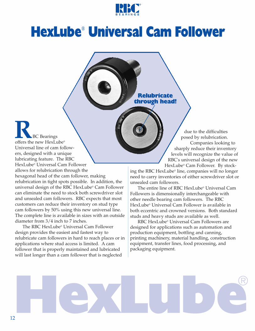
BC Bearingsoffers the new HexLube®
Universal line of cam follow-ers, designed with a unique lubricating feature. The RBCHexLube® Universal Cam Followerallows for relubrication through thehexagonal head of the cam follower, making relubrication in tight spots possible. In addition, theuniversal design of the RBC HexLube® Cam Followercan eliminate the need to stock both screwdriver slotand unsealed cam followers. RBC expects that mostcustomers can reduce their inventory on stud typecam followers by 50% using this new universal line.The complete line is available in sizes with an outsidediameter from 3/4 inch to 7 inches.
The RBC HexLube® Universal Cam Followerdesign provides the easiest and fastest way to relubricate cam followers in hard to reach places or inapplications where stud access is limited. A cam follower that is properly maintained and lubricatedwill last longer than a cam follower that is neglected
due to the difficultiesposed by relubrication.
Companies looking tosharply reduce their inventory
levels will recognize the value ofRBC's universal design of the new
HexLube® Cam Follower. By stock-ing the RBC HexLube® line, companies will no longerneed to carry inventories of either screwdriver slot orunsealed cam followers.
The entire line of RBC HexLube® Universal CamFollowers is dimensionally interchangeable withother needle bearing cam followers. The RBCHexLube® Universal Cam Follower is available inboth eccentric and crowned versions. Both standardstuds and heavy studs are available as well.
RBC HexLube® Universal Cam Followers are designed for applications such as automation andproduction equipment, bottling and canning,printing machinery, material handling, constructionequipment, transfer lines, food processing, and packaging equipment.
12
HexLube® Universal Cam Follower
R
®
Relubricatethrough head!
HexLube

13
BC developed the Universal Cam Followerproduct line to replace standard cam followers, anddelivered two obvious benefits. First, it is possible torelubricate the hex head cam follower through thehead. The hex head feature is the preferred mountingmethod for stud-type cam followers, and now it canbe relubricated in tight spots or when stud access is restricted. Second, the HexLube® can eliminate theneed to stock both screwdriver slot and unsealed cam followers. Your inventory can be reduced by about 50%!
RBC looked at the cam follower market and found358 line items and five manufacturers (1790 line items!)The challenge was to reduce the number of part num-bers needed to satisfy the market without sacrificingfeatures and benefits. The answer was the “UniversalCam Follower Product Line.” The HexLube® cam fol-lower allows lubrication through the head of the camfollower, eliminating the need to stock the screwdriverslot series. Also eliminated from the line were all un-sealed cam followers. Reducing your inventory by thislarge amount results in real savings. The end result isa product line with just 186 line items!
R
THE RBC HexLube®
SAVINGS AT EVERY TURN!✔ Inventory Reduction of About 50%
✔ Allows Relubrication in tight spots or when stud access is limited
✔ HexLube® Universal Cam Follower can eliminate the need to stock screwdriver slots or unsealed cam followers
✔ Sizes from 3/4" to 7" O.D.
✔ Eccentric and Crowned versions
✔ Available in Standard Stud and Heavy Stud
®HexLubeThe Universal Cam Follower Line by RBC
Relubricatethrough
Hex Head

14
withoutseal
1/29/165/8
11/163/47/8
11 1/81 1/41 3/81 1/21 5/81 3/41 7/822 1/42 1/22 3/433 1/43 1/24567
S 16S 18S 20S 22S 24S 28S 32S 36S 40S 44S 48S 52S 56S 60S 64S 72S 80S 88S 96S 104S 112S 128
---
S 16 LS 18 LS 20 LS 22 LS 24 LS 28 LS 32 LS 36 LS 40 LS 44 LS 48 LS 52 LS 56 LS 60 LS 64 LS 72 LS 80 LS 88 LS 96 LS 104 LS 112 LS 128 L
---
S 16 LWS 18 LWS 20 LWS 22 LWS 24 LWS 28 LWS 32 LWS 36 LWS 40 LWS 44 LWS 48 LWS 52 LWS 56 LWS 60 LWS 64 LWS 72 LWS 80 LWS 88 LWS 96 LWS 104 LWS 112 LWS 128 LWS 160 LWS 192 LWS 224 LW
.5000
.5625
.6250
.6875
.7500
.87501.00001.12501.25001.37501.50001.62501.75001.87502.00002.25002.50002.75003.00003.25003.50004.00005.00006.00007.0000
.375
.375
.438
.438
.500
.500
.625
.625
.750
.750
.875
.8751.0001.0001.2501.2501.5001.5001.7501.7502.0002.2502.7503.2503.750
.1900
.1900
.2500
.2500
.3750
.3750
.4375
.4375
.5000
.5000
.6250
.6250
.7500
.7500
.8750
.87501.00001.00001.25001.25001.37501.50002.00002.50003.0000
.625
.625
.750
.750
.875
.8751.0001.0001.2501.2501.5001.5001.7501.7502.0002.0002.2502.2502.5002.5002.7503.5005.0626.0007.688
.250
.250
.313
.313
.375
.375
.500
.500
.625
.625
.750
.750
.875
.8751.0001.0001.1251.1251.2501.2501.3751.5002.5623.0004.125
STUDROLLERPART NUMBER
Approx.Weight
[lbs]
SLShankLength
SD+.001- .000
B+.000- .005
NominalSize
SlottedHead
SlottedHead &Sealed
D+.000- .001
TLEff. Thread
Length
ThreadClass
2A
10-3210-321/4-281/4-283/8-243/8-24
7/16-207/16-201/2-201/2-205/8-185/8-183/4-163/4-167/8-147/8-14
1-141-14
1 1/4-121 1/4-121 3/8-121 1/2-12
2-122 1/2-12
3-12
.023
.031
.048
.051
.076
.100
.160
.190
.290
.340
.510
.610
.830
.9201.3201.6102.4802.8304.0404.7506.2207.440
18.70032.90053.900
Cam FollowersStandard Stud
Series S, S--L
withGlide-A-Seal®
All dimensions are in inches.
1 1/16" for sizes S 160 LW and larger.
G
SD
A
F
TL
1/32
THREADD
F
B SL
1
Hexlube™SocketHead &Sealed

15
G
SD
A
F
TL
1/32
THREADD
B SL
22223/163/163/163/163/163/163/163/163/163/163/163/163/163/161/41/41/41/41/4 NPT1/4 NPT1/4 NPT
5,0005,0005,0005,0005,0005,0004,5004,5003,9003,9003,1003,1002,6002,6002,2002,2002,0002,0001,6001,6001,4001,3001,000
800700
770770
1,0601,0601,8001,8002,3002,3004,2004,2005,0005,0006,4006,4009,6009,600
12,80012,80017,00017,00024,30030,00047,20062,90079,400
7.57.5 20 205555
150150200200390390750750900900
1,3001,3002,0002,0002,5003,0003,0003,0003,000
----
----
.093
.093
.093
.093
.093
.093
.093
.093
.125
.125
.125
.125
.125
.125
.187
.187
.187
.187
.187
.187
.187
1,1001,1001,7001,7003,1003,1004,8004,8006,6006,6008,8008,800
12,40012,40016,70016,70025,40025,40040,00040,00054,60073,100
102,000165,500237,800
310310610610
1,8401,8402,3902,3903,0003,0005,1005,1007,8007,800
10,00010,00012,50012,50021,00021,00024,75028,50055,00090,000
139,000
430480770850880
1,0301,6901,9002,4402,6803,3203,6004,5504,9006,5007,3009,400
10,40013,30014,40017,30022,00035,00052,00071,000
.1900
.1900
.2500
.2500
.3750
.3750
.4375
.4375
.5000
.5000
.6250
.6250
.7500
.7500
.8750
.87501.00001.00001.25001.25001.37501.50002.00002.50003.0000
.29
.29
.36
.36
.50
.50
.64
.64
.76
.76
.89
.891.051.051.201.201.311.312.002.002.392.623.504.505.25
-16-18-20-22-24-28-32-36-40-44-48-52-56-60-64-72-80-88-96-104-112-128-160-192-224
FLubeFitting
3
DynamicCapacity
C [lbf]
TrackCapacityat 40 Rc
[lbf]
Max.Allow.Load [lbf]
Max. 4Clamping
Torque[in∗lbf]
Min.Boss Dia.
BasicNumber
CAPACITIES MOUNTING DATA
SpeedLimit[rpm]
SocketHead
WrenchSize
GDia.
ALoc.
HousingBore
+.0005- .0000
1/81/81/81/83/163/161/41/41/41/45/165/165/165/167/167/161/21/25/85/85/83/47/8
11 1/4
HexLube® Universal Cam FollowersStandard Stud
Series S--LW
1
.250
.250
.250
.250
.312
.312
.375
.375
.437
.437
.500
.500
.562
.562
.625
.625
.687
.750
.8751.0001.250
2 Sizes S 16 through S 22 and S 16 L through S 22 L have a 1/8" hole at the flange end only.3 Sizes S 16 LW through S 22 LW cannot be relubricated.4 Torque may be doubled for completely dry threads.5 Bearing Static Capacity provided for comparison only.6 HexLube ® Cam Followers can be regreased through the hex head using a Lincoln #5803 or Alemite #6785 needle nozzle adapter.
6
StaticCapacity CO
[lbf] 5
Relubricatethrough
Hex Head

16
STUDROLLER
Approx.Weight
[lbs]
SLShankLength
SD+.001- .000
NominalSize
TLEff. Thread
Length
All dimensions are in inches.
1 1/16" for sizes CS 160 LW and larger.
SlottedHead &Sealed
PART NUMBER
D+.000- .001
B+.000- .005
CRCrownRadius
ThreadClass
2A
Crowned Cam FollowersStandard Stud
Series CS--L
G
SD
A
F
TL
1/32
THREADD
F
B SL
CR
1without
seal
withGlide-A-Seal®
Hexlube®
SocketHead &Sealed
.1900
.1900
.2500
.2500
.3750
.3750
.4375
.4375
.5000
.5000
.6250
.6250
.7500
.7500
.8750
.87501.00001.00001.25001.25001.37501.50002.00002.50003.0000
.625
.625
.750
.750
.875
.8751.0001.0001.2501.2501.5001.5001.7501.7502.0002.0002.2502.2502.5002.5002.7503.5005.0626.0007.688
.250
.250
.313
.313
.375
.375
.500
.500
.625
.625
.750
.750
.875
.8751.0001.0001.1251.1251.2501.2501.3751.5002.5623.0004.125
1/29/165/811/163/47/8
11 1/81 1/41 3/81 1/21 5/81 3/41 7/822 1/42 1/22 3/433 1/43 1/24567
.375
.375
.438
.438
.500
.500
.625
.625
.750
.750
.875
.8751.0001.0001.2501.2501.5001.5001.7501.7502.0002.2502.7503.2503.750
.5000
.5625
.6250
.6875
.7500
.87501.00001.12501.25001.37501.50001.62501.75001.87502.00002.25002.50002.75003.00003.25003.50004.00005.00006.00007.0000
CS 16 LWCS 18 LWCS 20 LWCS 22 LWCS 24 LWCS 28 LWCS 32 LWCS 36 LWCS 40 LWCS 44 LWCS 48 LWCS 52 LWCS 56 LWCS 60 LWCS 64 LWCS 72 LWCS 80 LWCS 88 LWCS 96 LWCS 104 LWCS 112 LWCS 128 LWCS 160 LWCS 192 LWCS 224 LW
7788
101012121414202020202424303030303030485660
.023
.031
.048
.051
.076
.100
.160
.190
.290
.340
.510
.610
.830
.9201.3201.6102.4802.8304.0404.7506.2207.440
18.70032.90053.900
10-3210-321/4-281/4-283/8-243/8-24
7/16-207/16-201/2-201/2-205/8-185/8-183/4-163/4-167/8-147/8-14
1-141-14
1 1/4-121 1/4-121 3/8-121 1/2-12
2-122 1/2-12
3-12
CS 16 LCS 18 LCS 20 LCS 22 LCS 24 LCS 28 LCS 32 LCS 36 LCS 40 LCS 44 LCS 48 LCS 52 LCS 56 LCS 60 LCS 64 LCS 72 LCS 80 LCS 88 LCS 96 LCS 104 LCS 112 LCS 128 L
---

17
G
SD
A
F
TL
1/32
THREADD
B SL
CR
----
FLubeFitting
3
DynamicCapacity
C [lbf]
TrackCapacityat 40 Rc
[lbf]
Max.Allow.Load [lbf]
Max. 4Clamping
Torque[in∗lbf]
Min.Boss Dia.
CAPACITIES MOUNTING DATA
SpeedLimit[rpm]
SocketHead
WrenchSize
GDia.
ALoc.
HousingBore
+.0005- .0000
BasicNumber
HexLube® Universal Cam FollowersStandard Stud
Series CS--LW
16
2 Sizes CS 16 through CS 22 and CS 16 L through CS 22 L have a 1/8" hole at the flange end only.3 Sizes CS 16 LW through CS 22 LW cannot be relubricated.4 Torque may be doubled for completely dry threads.5 Bearing Static Capacity provided for comparison only.6 HexLube ® Cam Followers can be regreased through the hex head using a Lincoln #5803 or Alemite #6785 needle nozzle adapter.
Relubricatethrough
Hex Head
StaticCapacity CO
[lbf] 5
5,0005,0005,0005,0005,0005,0004,5004,5003,9003,9003,1003,1002,6002,6002,2002,2002,0002,0001,6001,6001,4001,3001,000
800700
770770
1,0601,0601,8001,8002,3002,3004,2004,2005,0005,0006,4006,4009,6009,600
12,80012,80017,00017,00024,30030,00047,20062,90079,400
7.57.5 20 205555
150150200200390390750750900900
1,3001,3002,0002,0002,5003,0003,0003,0003,000
----
.093
.093
.093
.093
.093
.093
.093
.093
.125
.125
.125
.125
.125
.125
.187
.187
.187
.187
.187
.187
.187
1,1001,1001,7001,7003,1003,1004,8004,8006,6006,6008,8008,800
12,40012,40016,70016,70025,40025,40040,00040,00054,60073,100
102,000165,500237,800
310310610610
1,8401,8402,3902,3903,0003,0005,1005,1007,8007,800
10,00010,00012,50012,50021,00021,00024,75028,50055,00090,000
139,000
430480770850880
1,0301,6901,9002,4402,6803,3203,6004,5504,9006,5007,3009,400
10,40013,30014,40017,30022,00035,00052,00071,000
.1900
.1900
.2500
.2500
.3750
.3750
.4375
.4375
.5000
.5000
.6250
.6250
.7500
.7500
.8750
.87501.00001.00001.25001.25001.37501.50002.00002.50003.0000
.29
.29
.36
.36
.50
.50
.64
.64
.76
.76
.89
.891.051.051.201.201.311.312.002.002.392.623.504.505.25
-16-18-20-22-24-28-32-36-40-44-48-52-56-60-64-72-80-88-96-104-112-128-160-192-224
1/81/81/81/83/163/161/41/41/41/45/165/165/165/167/167/161/21/25/85/85/83/47/8
11 1/4
.250
.250
.250
.250
.312
.312
.375
.375
.437
.437
.500
.500
.562
.562
.625
.625
.687
.750
.8751.0001.250
222
23/163/163/163/163/163/163/163/163/163/163/163/163/163/161/41/41/41/41/4 NPT1/4 NPT1/4 NPT
18
withoutseal
withGlide-A-Seal®
BD
F
TL
1/32
THREAD
D
B SL
BL
ECC
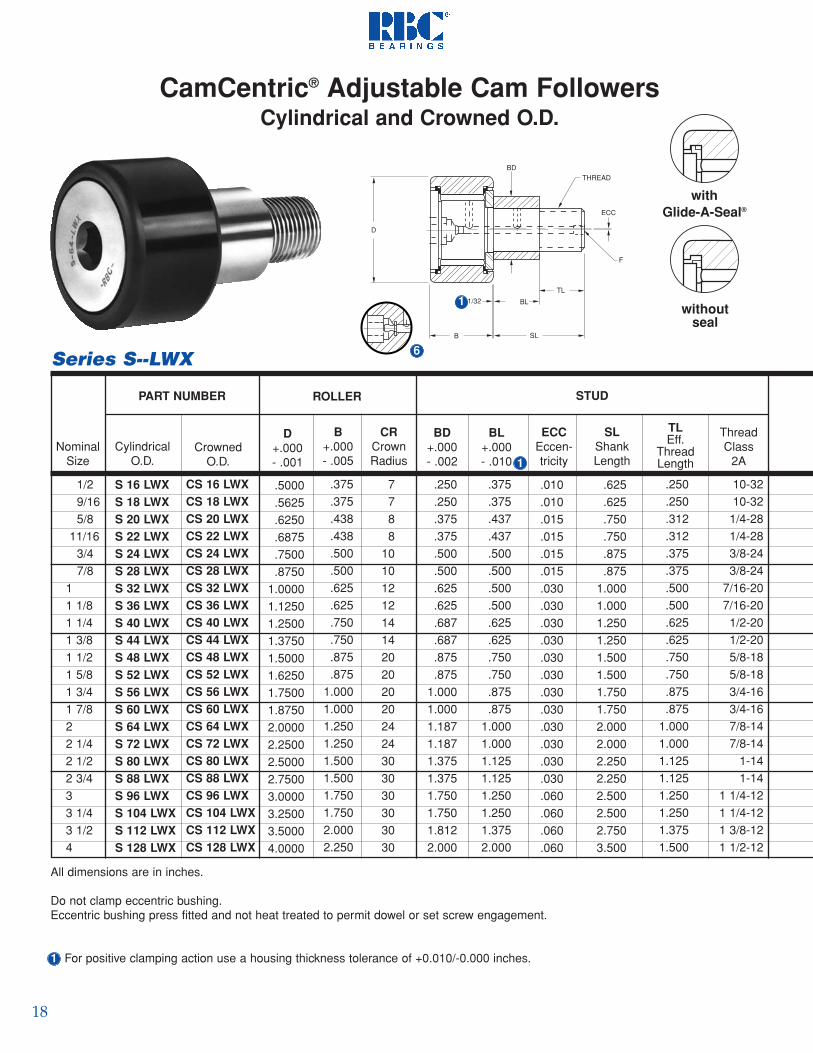
CamCentric® Adjustable Cam FollowersCylindrical and Crowned O.D.
S 16 LWXS 18 LWXS 20 LWXS 22 LWXS 24 LWXS 28 LWXS 32 LWXS 36 LWXS 40 LWXS 44 LWXS 48 LWXS 52 LWXS 56 LWXS 60 LWXS 64 LWXS 72 LWXS 80 LWXS 88 LWXS 96 LWXS 104 LWXS 112 LWXS 128 LWX
CS 16 LWXCS 18 LWXCS 20 LWXCS 22 LWXCS 24 LWXCS 28 LWXCS 32 LWXCS 36 LWXCS 40 LWXCS 44 LWXCS 48 LWXCS 52 LWXCS 56 LWXCS 60 LWXCS 64 LWXCS 72 LWXCS 80 LWXCS 88 LWXCS 96 LWXCS 104 LWXCS 112 LWXCS 128 LWX
NominalSize
CrownedO.D.
PART NUMBER
All dimensions are in inches.
Do not clamp eccentric bushing.Eccentric bushing press fitted and not heat treated to permit dowel or set screw engagement.
1 For positive clamping action use a housing thickness tolerance of +0.010/-0.000 inches.
10-3210-321/4-281/4-283/8-243/8-24
7/16-207/16-201/2-201/2-205/8-185/8-183/4-163/4-167/8-147/8-14
1-141-14
1 1/4-121 1/4-121 3/8-121 1/2-12
ThreadClass
2A
.250
.250
.312
.312
.375
.375
.500
.500
.625
.625
.750
.750
.875
.8751.0001.0001.1251.1251.2501.2501.3751.500
TLEff.
ThreadLength
.010
.010
.015
.015
.015
.015
.030
.030
.030
.030
.030
.030
.030
.030
.030
.030
.030
.030
.060
.060
.060
.060
.375
.375
.437
.437
.500
.500
.500
.500
.625
.625
.750
.750
.875
.8751.0001.0001.1251.1251.2501.2501.3752.000
BL+.000- .010
.250
.250
.375
.375
.500
.500
.625
.625
.687
.687
.875
.8751.0001.0001.1871.1871.3751.3751.7501.7501.8122.000
BD+.000- .002
.625
.625
.750
.750
.875
.8751.0001.0001.2501.2501.5001.5001.7501.7502.0002.0002.2502.2502.5002.5002.7503.500
SLShankLength
7788
101012121414202020202424303030303030
CRCrownRadius
.375
.375
.438
.438
.500
.500
.625
.625
.750
.750
.875
.8751.0001.0001.2501.2501.5001.5001.7501.7502.0002.250
B+.000- .005
.5000
.5625
.6250
.6875
.7500
.87501.00001.12501.25001.37501.50001.62501.75001.87502.00002.25002.50002.75003.00003.25003.50004.0000
D+.000- .001
ROLLER STUD
CylindricalO.D. 1
ECCEccen-tricity
1/29/165/8
11/163/47/8
11 1/81 1/41 3/81 1/21 5/81 3/41 7/822 1/42 1/22 3/433 1/43 1/24
Series S--LWX 6
1

19
BD
F
TL
1/32
THREAD
D
B SL
CR
BL
ECC
CamCentric® Adjustable Cam FollowersCylindrical and Crowned O.D.
Socket Head
Wrench Size
ApproxWeight
[lbs]
CAPACITIES
.025
.033
.056
.059
.088.11.18.21.32.37.57.67.92
1.011.461.752.703.054.465.176.658.22
22223/163/163/163/163/163/163/163/163/163/163/163/163/163/161/41/41/41/4
Speed Limit [rpm]
DynamicCapacity
C [lbf]
Max.Allow.Load [lbf]
TrackCapacity at 40 Rc
[lbf]
Max. 3Clamping
Torque[in∗lbf]
HousingBore+.002+.001
BasicNumber
7.57.520205555
150150200200390390750750900900
1,3001,3002,0002,0002,5003,000
310310610610
1,8401,8402,3902,3903,0003,0005,1005,1007,8007,800
10,00010,00012,50012,50021,00021,00024,75028,500
770770
1,0601,0601,8001,8002,3002,3004,2004,2005,0005,0006,4006,4009,6009,600
12,80012,80017,00017,00024,30030,000
5,0005,0005,0005,0005,0005,0004,5004,5003,9003,9003,1003,1002,6002,6002,2002,2002,0002,0001,6001,6001,4001,300
1/81/81/81/83/163/161/41/41/41/45/165/165/165/167/167/161/21/25/85/85/83/4
Series CS--LWX
FLube Fitting
MOUNTING DATA
1,1001,1001,7001,7003,1003,1004,8004,8006,6006,6008,8008,800
12,40012,40016,70016,70025,40025,40040,00040,00054,60073,100
430480770850880
1,0301,6901,9002,4402,6803,3203,6004,5504,9006,5007,3009,400
10,40013,30014,40017,30022,000
6
2 Sizes S 16 LWX through S 22 LWX and CS 16 LWX through CS 22 LWX cannot be relubricated.3 Torque may be doubled for completely dry threads.4 Bearing Static Capacity provided for comparison only.6 HexLube ® Cam Followers can be regreased through the hex head using a Lincoln #5803 or Alemite #6785 needle nozzle adapter.
1
Relubricatethrough
Hex Head
-16-18-20-22-24-28-32-36-40-44-48-52-56-60-64-72-80-88-96-104-112-128
StaticCapacity CO [lbf] 4
.250
.250
.375
.375
.500
.500
.625
.625
.687
.687
.875
.8751.0001.0001.1871.1871.3751.3751.7501.7501.8122.000

20
withoutseal
withGlide-A-Seal®
STUDROLLERPART NUMBER
Approx.Weight
[lbs]
SLShankLength
SD+.001- .000
B+.000- .005
NominalSize
SlottedHead
SlottedHead &Sealed
D+.000- .001
TLEff. Thread
Length
ThreadClass
2A
All dimensions are in inches.
1 1/16 inch for sizes H 160 LW and larger.
Cam FollowersHeavy Stud
Series H, H--L
SDA
F
TL
1/32
THREADD
B SL
G
F
1
HexLube®
SocketHead &Sealed
.625
.625
.750
.750
.875
.8751.0001.0001.2501.2501.5001.5001.7501.7502.0002.0002.2502.2502.5002.5002.7503.5005.0626.0007.688
.250
.250
.312
.312
.375
.375
.500
.500
.625
.625
.750
.750
.875
.8751.0001.0001.1251.1251.2501.2501.3751.5002.5623.0004.125
1/29/165/811/163/47/8
11 1/81 1/41 3/81 1/21 5/81 3/41 7/822 1/42 1/22 3/433 1/43 1/24567
H 16H 18H 20H 22H 24H 28H 32H 36H 40H 44H 48H 52H 56H 60H 64H 72H 80H 88H 96H 104H 112H 128
---
H 16 LH 18 LH 20 LH 22 LH 24 LH 28 LH 32 LH 36 LH 40 LH 44 LH 48 LH 52 LH 56 LH 60 LH 64 LH 72 LH 80 LH 88 LH 96 LH 104 LH 112 LH 128 L
---
H 16 LWH 18 LWH 20 LWH 22 LWH 24 LWH 28 LWH 32 LWH 36 LWH 40 LWH 44 LWH 48 LWH 52 LWH 56 LWH 60 LWH 64 LWH 72 LWH 80 LWH 88 LWH 96 LWH 104 LWH 112 LWH 128 LWH 160 LWH 192 LWH 224 LW
.5000
.5625
.6250
.6875
.7500
.87501.00001.12501.25001.37501.50001.62501.75001.87502.00002.25002.50002.75003.00003.25003.50004.00005.00006.00007.0000
.375
.375
.438
.438
.500
.500
.625
.625
.750
.750
.875
.8751.0001.0001.2501.2501.5001.5001.7501.7502.0002.2502.7503.2503.750
.2500
.2500
.3125
.3125
.4375
.4375
.6250
.6250
.7500
.7500
.8750
.87501.00001.00001.12501.12501.25001.25001.50001.50001.75002.00002.50003.00003.5000
1/4-281/4-28
5/16-245/16-247/16-207/16-205/8-185/8-183/4-163/4-167/8-147/8-14
1-141-14
1 1/8-121 1/8-121 1/4-121 1/4-121 1/2-121 1/2-121 3/4-12
2-122 1/2-12
3-123 1/2- 4
.026
.034
.057
.068
.083
.119
.200
.250
.380
.440
.630
.690
.9801.0801.5501.9002.7003.1404.4205.1506.950
10.30021.40036.40059.200

21
Relubricatethrough
SDA
F
TL
1/32
THREADD
B SL
G
CR
FLubeFitting
3
DynamicCapacity
C [lbf]
TrackCapacityat 40 Rc
[lbf]
Max.Allow.Load [lbf]
Max. 4Clamping
Torque[in∗lbf]
Min.Boss Dia.
CAPACITIES MOUNTING DATA
SpeedLimit[rpm]
SocketHead
WrenchSize
GDia.
ALoc.
BasicNumber
HousingBore
+.0005- .0000
HexLube® Universal Cam Followers
Series H--LW
1
6
2 Sizes H 16 through H 22 and H 16 L through H 22 L have a 1/8" hole at the flange end only.3 Sizes H 16 LW through H 22 LW cannot be relubricated.4 Torque may be doubled for completely dry threads.5 Bearing Static Capacity provided for comparison only.6 HexLube ® Cam Followers can be regreased through the hex head using a Lincoln #5803 or Alemite #6785 needle nozzle adapter.
StaticCapacity CO
[lbf] 5
770770970970
1,8001,8002,3002,3004,0004,0004,9004,9006,4006,4009,6009,600
12,90012,90017,00017,00024,30025,60044,90061,60079,400
20205555
150150390390750750900900
1,3501,3501,7001,7002,0502,0503,0003,0003,0003,0003,0003,0003,000
----
----
.093
.093
.093
.093
.093
.093
.093
.093
.125
.125
.125
.125
.125
.125
.187
.187
.187
.187
.187
.187
.187
1/81/81/81/83/163/161/41/41/41/45/165/165/165/167/167/161/21/25/85/85/83/47/8
11 1/4
1,5901,5902,5002,5004,1504,1506,1506,1508,5008,500
11,30011,30015,85015,85021,20021,20033,00033,00049,90049,90063,25089,550
136,000161,300237,800
700700
1,2001,2002,9202,9204,1004,1005,8005,8007,9007,900
11,40011,40016,70016,70025,40025,40036,60036,60051,00068,00099,000
160,000217,000
.2500
.2500
.3125
.3125
.4375
.4375
.6250
.6250
.7500
.7500
.8750
.87501.00001.00001.12501.12501.25001.25001.50001.50001.75002.00002.50003.00003.5000
.34
.34
.47
.47
.60
.60
.78
.781.001.001.091.091.251.251.401.401.701.702.002.002.452.753.254.004.50
-16-18-20-22-24-28-32-36-40-44-48-52-56-60-64-72-80-88-96
-104-112-128-160-192-224
5,0005,0005,0005,0005,0005,0004,5004,5003,9003,9003,1003,1002,6002,6002,2002,2002,0002,0001,6001,6001,4001,3001,000
800700
430480770850
1,0701,2401,6901,9002,4402,6803,3203,6004,5504,9006,5007,3009,400
10,40013,30014,40017,30022,00035,00052,00071,000
22223/163/163/163/163/163/163/163/163/163/163/163/163/163/161/41/41/41/41/4 NPT1/4 NPT1/4 NPT
.250
.250
.250
.250
.312
.312
.375
.375
.437
.437
.500
.500
.562
.562
.625
.625
.687
.750
.8751.0001.250

22
withoutseal
withGlide-A-Seal®
STUDROLLERPART NUMBER
SD+.001- .000
NominalSize
TLEff. Thread
Length
All dimensions are in inches.
1 1/16" for size CH 160 LW and larger.
B+.000- .005
D+.000- .001
CRCrownRadius
ThreadClass
2A
SLShankLength
ApproxWeight
[lbs]
Crowned Cam FollowersHeavy Stud
Series CH--L
SDA
F
TL
1/32
THREADD
B SL
G
F
CR
1
SlottedHead &Sealed
HexLube®
SocketHead &Sealed
.625
.625
.750
.750
.875
.8751.0001.0001.2501.2501.5001.5001.7501.7502.0002.0002.2502.2502.5002.5002.7503.5005.0626.0007.688
.250
.250
.312
.312
.375
.375
.500
.500
.625
.625
.750
.750
.875
.8751.0001.0001.1251.1251.2501.2501.3751.5002.5623.0004.125
1/29/165/8
11/163/47/8
11 1/81 1/41 3/81 1/21 5/81 3/41 7/822 1/42 1/22 3/433 1/43 1/24567
1/4-281/4-28
5/16-245/16-247/16-207/16-205/8-185/8-183/4-163/4-167/8-147/8-14
1-141-14
1 1/8-121 1/8-121 1/4-121 1/4-121 1/2-121 1/2-121 3/4-12
2-122 1/2-12
3-123 1/2- 4
.375
.375
.438
.438
.500
.500
.625
.625
.750
.750
.875
.8751.0001.0001.2501.2501.5001.5001.7501.7502.0002.2502.7503.2503.750
.5000
.5625
.6250
.6875
.7500
.87501.00001.12501.25001.37501.50001.62501.75001.87502.00002.25002.50002.75003.00003.25003.50004.00005.00006.00007.0000
CH 16 LWCH 18 LWCH 20 LWCH 22 LWCH 24 LWCH 28 LWCH 32 LWCH 36 LWCH 40 LWCH 44 LWCH 48 LWCH 52 LWCH 56 LWCH 60 LWCH 64 LWCH 72 LWCH 80 LWCH 88 LWCH 96 LWCH 104 LWCH 112 LWCH 128 LWCH 160 LWCH 192 LWCH 224 LW
7788
101012121414202020202424303030303030485660
.2500
.2500
.3125
.3125
.4375
.4375
.6250
.6250
.7500
.7500
.8750
.87501.00001.00001.12501.12501.25001.25001.50001.50001.75002.00002.50003.00003.5000
CH 16 LCH 18 LCH 20 LCH 22 LCH 24 LCH 28 LCH 32 LCH 36 LCH 40 LCH 44 LCH 48 LCH 52 LCH 56 LCH 60 LCH 64 LCH 72 LCH 80 LCH 88 LCH 96 LCH 104 LCH 112 LCH 128 L
---
.026
.034
.057
.068
.083
.119
.200
.250
.380
.440
.630
.690
.9801.0801.5501.9002.7003.1404.4205.1506.950
10.30021.40036.40059.200

23
SDA
F
TL
1/32
THREADD
B SL
G
CR
FLubeFitting
3
DynamicCapacity
C [lbf]
TrackCapacityat 40 Rc
[lbf]
Max.Allow.Load [lbf]
Max. 4Clamping
Torque[in∗lbf]
Min.Boss Dia.
CAPACITIES MOUNTING DATA
SpeedLimit[rpm]
SocketHead
WrenchSize
GDia.
ALoc.
HousingBore
+.0005- .0000
BasicNumber
HexLube® Universal Cam FollowersHeavy Stud
Series CH--LW
1
6
2 Sizes CH 16 L through CH 22 L have a 1/8 inch hole at the flange end only.3 Sizes CH 16 LW through CH 22 LW cannot be relubricated.4 Torque may be doubled for completely dry threads.5 Bearing Static Capacity provided for comparison only.6 HexLube® Cam Followers can be regreased through the hex head using a Lincoln #5803 or Alemite #6785 needle nozzle adapter.
22223/163/163/163/163/163/163/163/163/163/163/163/163/163/161/41/41/41/41/4 NPT1/4 NPT1/4 NPT
20205555
150150390390750750900900
1,3501,3501,7001,7002,0502,0503,0003,0003,0003,0003,0003,0003,000
----
----
.093
.093
.093
.093
.093
.093
.093
.093
.125
.125
.125
.125
.125
.125
.187
.187
.187
.187
.187
.187
.187
1,5901,5902,5002,5004,1504,1506,1506,1508,5008,500
11,30011,30015,85015,85021,20021,20033,00033,00049,90049,90063,25089,550
136,000161,300237,800
700700
1,2001,2002,9202,9204,1004,1005,8005,8007,9007,900
11,40011,40016,70016,70025,40025,40036,60036,60051,00068,00099,000
160,000217,000
.2500
.2500
.3125
.3125
.4375
.4375
.6250
.6250
.7500
.7500
.8750
.87501.00001.00001.12501.12501.25001.25001.50001.50001.75002.00002.50003.00003.5000
.34
.34
.47
.47
.60
.60
.78
.781.001.001.091.091.251.251.401.401.701.702.002.002.452.753.254.004.50
-16-18-20-22-24-28-32-36-40-44-48-52-56-60-64-72-80-88-96
-104-112-128-160-192-224
5,0005,0005,0005,0005,0005,0004,5004,5003,9003,9003,1003,1002,6002,6002,2002,2002,0002,0001,6001,6001,4001,3001,000
800700
430480770850
1,0701,2401,6901,9002,4402,6803,3203,6004,5504,9006,5007,3009,400
10,40013,30014,40017,30022,00035,00052,00071,000
770770970970
1,8001,8002,3002,3004,0004,0004,9004,9006,4006,4009,6009,600
12,90012,90017,00017,00024,30025,60044,90061,60079,400
.250
.250
.250
.250
.312
.312
.375
.375
.437
.437
.500
.500
.562
.562
.625
.625
.687
.750
.8751.0001.250
1/81/81/81/83/163/161/41/41/41/45/165/165/165/167/167/161/21/25/85/85/83/47/8
11 1/4
Relubricatethrough
Hex Head
StaticCapacity CO
[lbf] 5

24
Yoke RollersCylindrical and Crowned O.D.
PART NUMBER
3/47/8
11 1/81 1/41 3/81 1/21 5/81 3/41 7/822 1/42 1/22 3/433 1/43 1/24567
Y 24Y 28Y 32Y 36Y 40Y 44Y 48Y 52Y 56Y 60Y 64Y 72Y 80Y 88Y 96Y 104Y 112Y 128Y 160Y 192Y 224
Y 24 LY 28 LY 32 LY 36 LY 40 LY 44 LY 48 LY 52 LY 56 LY 60 LY 64 LY 72 LY 80 LY 88 LY 96 LY 104 LY 112 LY 128 LY 160 LY 192 LY 224 L
.5625
.5625
.6875
.6875
.8125
.8125
.9375
.93751.06251.06251.31251.31251.56251.56251.81251.81252.06252.31252.87503.37503.8750
.093
.093
.093
.093
.093
.093
.093
.093
.093
.093
.093
.093
.125
.125
.125
.125
.125
.125
.187
.187
.187
BOverallWidth+.005- .010
HOil
Hole
Sealed &Crowned
O.D.WithSeals
WithoutSeals
NominalSize
All dimensions are in inches.
Axial clamping of the inner ring is recommended.
.500
.500
.625
.625
.750
.750
.875
.8751.0001.0001.2501.2501.5001.5001.7501.7502.0002.2502.7503.2503.750
.750
.8751.0001.1251.2501.3751.5001.6251.7501.8752.0002.2502.5002.7503.0003.2503.5004.0005.0006.0007.000
101012121414202020202424303030303030485660
ROLLER
B1
+.000- .005
D+.000- .001
.2496
.2496
.3121
.3121
.3746
.3746
.4371
.4371
.4996
.4996
.6246
.6246
.7496
.7496
.9995
.99951.12451.24951.74952.24952.7495
.2502
.2502
.3127
.3127
.3752
.3752
.4377
.4377
.5002
.5002
.6252
.6252
.7502
.75021.00011.00011.12511.25011.75012.25012.7501
dINSIDE DIAMETER
Max.Min.Nom.
1/41/45/165/163/83/87/167/161/21/25/85/83/43/4
111 1/81 1/41 3/42 1/42 3/4
CY 24 LCY 28 LCY 32 LCY 36 LCY 40 LCY 44 LCY 48 LCY 52 LCY 56 LCY 60 LCY 64 LCY 72 LCY 80 LCY 88 LCY 96 LCY 104 LCY 112 LCY 128 LCY 160 LCY 192 LCY 224 L
Series Y, Y--L
B
B
H
dD
1
CRCrownRadius
withoutseal
withGlide-A-Seal®

25
1 Normal operating loads should not exceed 50% of the bearing dynamic capacity.2 Bearing Static Capacity provided for comparison only.
Yoke RollersCylindrical and Crowned O.D.
3,9303,9303,1403,1402,6202,6202,2502,2501,9701,9701,5701,5701,3101,3101,0601,060
980940720590520
1,8001,8002,3002,3004,2004,2005,0005,0006,4006,4009,6009,600
12,80012,80017,00017,00024,30030,00047,20062,90079,400
8801,0301,6901,9002,4402,6803,3203,6004,5504,9006,5007,3009,400
10,40013,30014,40017,30022,00035,00052,00071,000
.2497
.2497
.3122
.3122
.3747
.3747
.4372
.4372
.4997
.4997
.6247
.6247
.7497
.7497
.9996
.99961.12461.24961.74962.24962.7496
.2493
.2493
.3118
.3118
.3743
.3743
.4368
.4368
.4993
.4993
.6243
.6243
.7493
.7493
.9991
.99911.12411.24911.74912.24912.7491
.2505
.2505
.3130
.3130
.3755
.3755
.4380
.4380
.5007
.5007
.6257
.6257
.7507
.75071.00081.00081.12581.25081.75082.25082.7508
.2501
.2501
.3126
.3126
.3751
.3751
.4376
.4376
.5003
.5003
.6253
.6253
.7503
.75031.00031.00031.12531.25031.75032.25032.7503
.50
.50
.64
.64
.76
.76
.89
.891.051.051.201.201.311.312.002.002.392.623.504.505.25
.051
.067
.115
.150
.200
.260
.350
.440
.580
.670
.9201.2301.7502.2002.8803.4904.5206.760
12.70021.40034.200
-24-28-32-36-40-44-48-52-56-60-64-72-80-88-96
-104-112-128-160-192-224
DynamicCapacityC [lbf] 1
TrackCapacity@ 40 Rc
[lbf] Min. Max.
Transition Fit Press Fit
MOUNTING DATACAPACITIES
Min.
Min.BossDia.
Approx.Weight
[lbs]Basic
Number
SpeedLimit[rpm]
Series CY--L
B
CR
B
H
dD
1
Max.
withoutseal
withGlide-A-Seal®
StaticCapacity
CO [lbf] 2
4,1504,1506,1506,1508,5008,500
11,30011,30015,85015,85021,20021,20033,00033,00049,90049,90063,25089,550
136,000165,500237,800

26
Caged Roller Followers
.495
.620
.620
.620
.745
.745
.745
.745
.995
.995
.995
.995
.995
.9951.2451.2451.2451.2451.2451.2451.245
.066
.076
.129
.140
.230
.230
.320
.330
.590
.560
.690
.580
.860
.8601.3401.3101.6101.9102.2302.5902.750
————
IR 7153, IR 7153 CIR 7153, IR 7153 CIR 7173, IR 7173 CIR 7173, IR 7173 CIR 7194, IR 7194 CIR 7194, IR 7194 CIR 7234IR 7234IR 7254, IR 7254 DIR 7254, IR 7254 DIR 7275, IR 7275 CIR 7275, IR 7275 CIR 7295, IR 7295 CIR 7315, IR 7315 CIR 7335IR 7355, IR 7355 DIR 8405, IR 8405 D
.5005
.5005
.6258
.6258
.7509
.7509
.8759
.87591.00091.00091.25101.25101.37601.37601.50101.50101.62601.75101.87602.00112.2511
.5014
.5014
.6267
.6267
.7518
.7518
.8768
.87681.00181.00181.25191.25191.37691.37691.50191.50191.62691.75201.87702.00212.2521
.04
.04
.06
.06
.06
.06
.06
.06
.08
.08
.08
.08
.08
.08
.08
.08
.08
.10
.10
.10
.10
Approx.Weight
[lbs]
MatchingInner Rings
(See page 28)Max.Min.NominalMin.
All dimensions are in inches.
Normal operating loads should not exceed the bearing dynamic capacity.
Roller followers used without inner rings require a shaft with minimum hardness of Rc 58 and surface finish of 16 rms or better.
Standard configuration of roller follower series SRF-- SS is with seal lips facing outward. To specify roller followers with seal lips facinginward, replace suffix -SS with suffix -RR. (example: SRF 30 RR).
PART NUM-BER
B+.000- .005
1/21/25/85/83/43/47/87/8
111 1/41 1/41 3/81 3/81 1/21 1/21 5/81 3/41 7/822 1/4
SRF 20SRF 20 SSSRF 25SRF 25 SSSRF 30SRF 30 SSSRF 35SRF 35 SSSRF 40SRF 40 SSSRF 45SRF 45 SSSRF 50SRF 50 SSSRF 55SRF 55 SSSRF 60SRF 65SRF 70SRF 75SRF 80
1.0001.0001.2501.2501.5001.5001.7501.7502.0002.0002.2502.2502.5002.5002.7502.7503.0003.2503.5003.7504.000
.999
.9991.2491.2491.4991.4991.7491.7491.9991.9992.2492.2492.4992.4992.7492.7492.9993.2493.4993.7493.999
Max.
ROLLER
D
Fw
Inside Diameter
Series SRF without seals
r1
B
D Fw
r1
CornerRadius

27
1 Bearing Static Capacity provided for comparison only.
2 For oscillatory application with angle of oscillation less than critical angle,consult RBC engineering department for revised fatigue calculation.
3 Speed limit of sealed roller followers is determined by maximum seal surface speed.For roller followers without seals, speed limit may be increased by 30% with oil lubrication.
2,2001,3003,3001,6005,9002,7006,5003,000
11,3007,500
13,9008,400
15,7008,900
22,80015,80020,70026,60023,80025,80026,700
1,9001,2002,7001,6004,4002,3004,7002,4006,9005,0007,8004,9008,3005,100
11,5008,0009,400
12,50010,10010,60012,700
1,2801,6501,9501,9502,9002,9003,4003,4005,2005,2005,8005,8006,4506,4509,2509,250
10,10010,50011,30012,10012,950
60.060.060.160.150.551.247.548.141.841.835.636.032.334.432.331.230.128.526.824.928.8
10,9007,6008,7006,1007,2005,1006,2004,4005,4003,8004,3003,1003,9002,8003,6002,5003,3003,0002,8002,7002,300
.4996
.4996
.6246
.6246
.7496
.7496
.8745
.8746
.9995
.99951.24951.24951.37451.37451.49951.49951.62451.74951.87451.99942.2494
.5000
.5000
.6250
.6250
.7500
.7500
.8750
.87501.00001.00001.25001.25001.37501.37501.50001.50001.62501.75001.87502.00002.2500
SRF 20SRF 20 SSSRF 25SRF 25 SSSRF 30SRF 30 SSSRF 35SRF 35 SSSRF 40SRF 40 SSSRF 45SRF 45 SSSRF 50SRF 50 SSSRF 55SRF 55 SSSRF 60SRF 65SRF 70SRF 75SRF 80
Min.Max.
Speed Limit(grease)[rpm] 3
CriticalAngle
[deg] 2
Track Capacity@ 40 Rc
[lbf]
Recommended Shaft Diameter(without Inner Ring)Dynamic
CapacityC [lbf]
CAPACITIES
PARTNUMBER
Series SRF--SS with seals
FwD
r1
B
StaticCapacity
CO [lbf] 1
Caged Roller Followers

28
dInside Diameter
FOutside Diameter
IR 7153IR 7153 CIR 7173IR 7173 CIR 7194IR 7194 CIR 7234IR 7254 DIR 7254IR 7275IR 7275 CIR 7295IR 7295 CIR 7315IR 7315 CIR 7335IR 7355 DIR 7355IR 8405 DIR 8405
PART NUMBER
All dimensions are in inches.
r2
Shaft FilletMax
.04
.04
.04
.04
.04
.04
.04
.04
.04
.06
.06
.06
.06
.06
.06
.06
.06
.06
.06
.06
BWidth+ .000- .005
.760
.760
.760
.7601.0101.0101.0101.0101.0101.2601.2601.2601.2601.2601.2601.2601.2601.2601.2601.260
Min.
.7488
.7488
.8738
.8738
.9988
.99881.24851.37351.37351.49841.49841.62341.62341.74841.74841.87341.99821.99822.24822.2482
.7493
.7493
.8743
.8743
.9993
.99931.24911.37411.37411.49901.49901.62401.62401.74901.74901.87401.99891.99892.24892.2489
Max.
3/43/47/87/8
111 1/41 3/81 3/81 1/21 1/21 5/81 5/81 3/41 3/41 7/8222 1/42 1/4
Nominal
.5000
.5625
.6250
.6875
.7500
.81251.00001.00001.12501.18751.25001.31251.37501.43751.50001.56251.62501.68751.68751.7500
.4996
.5621
.6246
.6871
.7496
.8120
.9995
.99951.12451.18701.24951.31201.37451.43701.49951.56201.62451.68701.68701.7495
Max.Min.Nominal
1/29/165/811/163/413/16
111 1/81 3/161 1/41 5/161 3/81 7/161 1/21 9/161 5/81 11/161 11/161 3/4
Series IR
Precision Ground Inner RingsFor Use with Caged Roller Followers
d
B
F
r2

29
RECOMMENDED SHAFT DIAMETER
PART NUMBER
Transition Fit - ISO g6 Press Fit - ISO m5
Series SRF with Inner Ring
Precision Ground Inner RingsFor Use with Caged Roller Followers
IR 7153IR 7153 CIR 7173IR 7173 CIR 7194IR 7194 CIR 7234IR 7254 DIR 7254IR 7275IR 7275 CIR 7295IR 7295 CIR 7315IR 7315 CIR 7335IR 7355 DIR 7355IR 8405 DIR 8405
Mean Fit
.0006T
.0006T
.0006T
.0006T
.0007T
.0007T
.0007T
.0007T
.0008T
.0008T
.0008T
.0008T
.0008T
.0008T
.0008T
.0008T
.0008T
.0008T
.0008T
.0008T
Min.
.5003
.5628
.6253
.6878
.7503
.81281.00031.00031.12531.18791.25041.31291.37541.43791.50041.56291.62541.68791.68791.7504
Max.
.5006
.5631
.6256
.6881
.7507
.81321.00071.00071.12571.18831.25081.31331.37581.43831.50081.56331.62581.68831.68831.7508
.0003L
.0003L
.0003L
.0003L
.0003L
.0003L
.0003L
.0003L
.0003L
.0004L
.0004L
.0004L
.0004L
.0004L
.0004L
.0004L
.0004L
.0004L
.0004L
.0004L
Mean Fit
.4993
.5618
.6243
.6868
.7492
.8117
.9992
.99921.12421.18651.24901.31151.37401.43651.49901.56151.62401.68651.68651.7490
Min.Max.
.4997
.5622
.6247
.6872
.7497
.8122
.9997
.99971.12471.18711.24961.31211.37461.43711.49961.56211.62461.68711.68711.7496
Approx.Weight
[lbs]
.050
.040
.059
.046
.094
.072
.121
.192
.134
.228
.183
.247
.201
.269
.217
.288
.366
.308
.609
.544
MatchingRoller Followers(See page 26)
SRF 30, SRF 30 SSSRF 30, SRF 30 SSSRF 35, SRF 35 SSSRF 35, SRF 35 SSSRF 40, SRF 40 SSSRF 40, SRF 40 SSSRF 45, SRF 45 SSSRF 50, SRF 50 SSSRF 50, SRF 50 SSSRF 55, SRF 55 SSSRF 55, SRF 55 SSSRF 60SRF 60SRF 65SRF 65SRF 70SRF 75SRF 75SRF 80SRF 80

30
Mast Guide and Carriage Rollers
PARTNUMBER
dInside Diameter
DOutside Diameter
Min. Max.Min. Max.Nom.
B2
Inner RingWidth
B1
Outer RingWidth
r1
CornerRadius
DynamicCapacity
C [lbf]
1/2 - 13 thread.7495.7495.7495.7870.8745.9838.9995
1.00051.17981.24951.24941.37751.37751.37751.37751.37751.37751.37751.37751.49951.4995
.7500
.7500
.7500
.7874
.8750
.98431.00001.00101.18031.25001.25001.37801.37801.37801.37801.37801.37801.37801.37801.50001.5000
2.24901.85902.24902.24902.24322.24902.99602.49802.24952.71302.99603.24503.22003.71703.97003.97003.99903.99903.99904.00002.74004.0000
2.25001.86002.25002.25002.24402.25003.00602.50002.25002.72803.00603.25003.22603.72503.97503.97504.00004.00004.00004.01002.75004.0100
5,3005,1008,5005,9004,800
18,40010,20011,30011,10014,10010,20011,70010,00012,80014,60010,10018,60014,60015,00014,30018,30014,300
5,3004,9009,5006,0004,600
31,10011,40018,30018,00018,20011,40015,30010,30014,00016,5009,500
23,40016,50016,10015,70032,10015,700
1.40200.55000.96300.77400.58531.76001.02501.27001.26001.00201.02501.00000.66900.86000.82700.82701.18500.90500.82701.13701.53501.1370
0.81200.48900.99500.81200.72831.74000.97501.25001.25001.00200.97501.00001.00501.00001.13001.30001.18501.18801.26001.08701.74601.0870
0.125000.040000.187500.125000.020000.120000.336000.080000.040000.031250.336000.080000.120000.375000.125000.120000.375000.250000.250000.336000.435000.33600
dF
B
B
2
1
r1
All dimensions are in inches, unless otherwise noted.
Designs vary and may not be interchangeable.
Confirm correct part number when ordering.
For sizes not listed above, contact RBC.
Contact RBC for additional design characteristics or for assistance with new applications.
D
StaticCapacityCO [lbf]
7522975066-1074392-274444T75342T74780-10T75016-10T74970T74962-10T74879T7501674501RRT74850-10T749267452474703743897449874709T75015-10T74908T75015
3/43/43/4
20 mm7/8
25 mm11
30 mm1 1/41 1/4
35 mm35 mm35 mm35 mm35 mm35 mm35 mm35 mm
1 1/2 1 1/2

31
Mast Guide and Carriage Rollers
PARTNUMBER
dInside Diameter
DOutside Diameter
Min. Max.Min. Max.Nom.
B2
Inner RingWidth
B1
Outer RingWidth
r1
CornerRadius
DynamicCapacity
C [lbf]
1.55991.57431.57431.77121.77121.77121.77121.96801.96801.99952.00002.16482.16482.16482.24942.75532.81192.99943.04943.14903.24943.6240
2.75002.98002.98003.72503.48003.99005.00253.97804.47804.06753.48005.39006.00306.44006.44007.06305.04006.37005.01808.00306.01006.4400
18,60013,80013,80016,20019,50016,20019,50024,10024,10019,20020,10043,70037,20051,60045,30076,80023,90034,20026,20068,20059,90053,900
33,20020,00020,00018,40026,10018,40023,50031,70031,70024,90049,50056,50042,90075,50054,900
122,90038,80045,00047,600
112,30091,40088,500
0.500000.060000.060000.240000.080000.290000.312500.093750.093750.125000.031250.187500.437500.427000.250000.460000.187500.225000.187500.625000.125000.31250
Typical Mast Guide and Carriage Roller Configurations
All dimensions are in inches, unless otherwise noted.
Designs vary and may not be interchangeable; some inner rings are not centered.
Confirm correct part number when ordering.
For sizes not listed above, contact RBC.
Contact RBC for additional design characteristics or for assistance with new applications.
T74897T74997-10T74997T75600T74996T74794-15T74924T74995T74995-1074812-10T74284T75291T74966T74931T74636-19T75003T74806T74947-10T74711T75088T74977T74779-11
1 9/1640 mm40 mm45 mm45 mm45 mm45 mm50 mm50 mm
22
55 mm55 mm55 mm
2 1/470 mm
2 13/1633
80 mm3 1/43 5/8
1.56041.57481.57481.77171.77171.77171.77171.96851.96852.00002.00402.16542.16542.16542.25002.75592.81253.00003.05003.14963.25003.6250
2.74002.97002.97003.72003.47003.98504.99753.97204.47204.05753.47005.37005.99706.43006.43007.05305.03706.27005.00807.99705.99006.4300
1.37500.87500.87500.74801.12500.74801.04001.12501.12501.34202.84401.72501.23001.06202.25002.75001.25001.14201.25002.63002.25002.1250
1.62501.00001.00001.00001.25501.12101.25001.25501.25501.28001.00001.83301.50002.13502.25003.12001.25001.51001.25003.38002.25002.250
StaticCapacityCO [lbf]

32
PART NUMBER
Min. Max.
DynamicCapacity
C [lbf]
dInside
Diameter
Nom.
DOutside
Diameter
Nom.
DFFlange
Diameter
Nom.
B2
Inner RingWidth
Nom.
BFWidth
betweenFlanges
Nom.
B1
Outer RingWidth
Chain Sheaves
V75582V7560574393-1V75204V75204-10V75024V75606V74929-10V75431V75608V75652V74899V74899-117475974797V74893V75039V75031-10V74954-10V75071-10V75294V75294V74961V75029
0.49960.74960.74980.75000.75000.78700.98370.98391.14531.37741.57431.57431.57431.74951.74951.74951.77121.77121.77121.77121.77121.96803.99934.5000
0.50020.75050.75030.75700.75700.78740.98440.98431.18111.37801.57481.57481.57481.75001.75001.75001.77171.77171.77171.77171.77171.96854.00004.5007
All dimensions are in inches.
For sizes not listed above, contact RBC.
Contact RBC for additional design characteristics or for assistance with new applications.
1.89303.00002.30002.25003.75002.24303.15553.38503.16143.54923.76003.76003.51005.50503.72504.00504.01004.57203.72804.26004.51004.5100
10.010010.0100
2.48403.39612.62502.62504.12503.00303.86423.88503.55514.25794.25004.25004.00006.13504.37504.37504.38505.01004.37504.57005.13505.0000
11.010011.0100
1.11801.56691.37001.88001.88001.68701.92911.00000.74801.92910.90550.90600.90601.76001.56301.78501.25001.25001.44001.00000.98401.92504.38505.5000
7,80013,20011,40015,90017,10015,90027,20012,80011,90021,10015,40013,60013,60044,40027,00027,00023,10024,80027,00022,60022,60032,300
179,000201,700
10,00026,40014,30033,50040,30021,40036,10014,00012,30026,80018,40015,60015,60057,80032,50032,50025,40028,10032,50025,00025,00039,600
299,400360,000
dDF
B
B
2
1
BF
D
StaticCapacityCO [lbf]
0.72001.17131.08901.44501.44501.10001.28540.91601.09451.28541.07101.00000.87501.37501.37501.37501.31701.81701.37501.07001.37501.33003.63504.7500
1.12001.52011.31201.81501.81501.56701.87011.20801.42911.87011.35201.31201.12501.76001.76001.76001.50002.21201.75001.35001.76001.96004.38505.5000

33
ABBAABBAAAAA
PART NUMBER
dInside
Diameter+0.0000- 0.0005Type
6
All dimensions are in inches.
For sizes not listed above, contact RBC.
23456
Without seals.Inner ring part number IR 7295C must be ordered separately.Inner ring part number IR 8406 H must be ordered separately.Inner ring part number IR 7439 must be ordered separately.Inner ring is 0.010 inches wider than outer ring.Inner ring width 1.125 inches.
1
Toothless Sprockets
1.25001.37501.37501.37801.57481.75001.75001.75001.77171.77171.77172.5000
DOutside
Diameter+0.000- 0.002
3.1403.4273.4273.1744.0574.3054.3053.7553.7554.0054.6834.895
B
Width+.000- .010
B1LandWidth+.000- .010
D1ShoulderDiameter
+.000- .020
2.5602.9152.9152.7413.4933.6413.6413.1353.1353.1353.9384.045
.470
.585
.585
.459
.575
.692
.692
.595
.595
.720
.692
.940
1.0051.2501.250.690.906
1.5001.5001.1301.1301.130.989
1.255
DynamicCapacity
C [lbf]
11,1009,4009,3008,200
11,00015,10013,80016,80015,20015,20013,90020,000
17,20020,70018,20010,30015,60033,80028,80027,90024,70024,70018,00038,300
SuggestedRollerChain
Number
6080806080
1001008080
100100120
dD
B1
B
D1
Type A Type B
5
5
55
74925SJ 74690 1 2SJ 74690 RR 274698-1074499-10SJ 74839 1 3SJ 74839 SS 47506074990749917480974992
StaticCapacityCO [lbf]

34
Airframe Needle Roller Bearings
4 NBC 612 ZP5 NBC 713 ZP6 NBC 914 YZP7 NBC 1015 YZP8 NBC 1218 YZP9 NBC 1419 YZP
10 NBC 1620 YZP12 NBC 1822 YZP14 NBC 2026 YZP16 NBC 2028 YZP20 NBC 2032 YZP24 NBC 2036 YZP28 NBC 2040 YZP32 NBC 2044 YZP36 NBC 2048 YZP40 NBC 2052 YZP44 NBC 2056 YZP48 NBC 2060 YZP52 NBC 2064 YZP56 NBC 2070 YZP60 NBC 2074 YZP64 NBC 2078 YZP
PART NUMBER
All dimensions are in inches
All exposed surfaces plated for corrosion resistance.
.094
.094
.125
.125
.125
.156
.156
.156
.156
.156
.156
.156
.156
.156
.156
.156
.156
.156
.156
.156
.156
.156
G
OuterRing
GrooveWidth
- -
.188
.188
.188
.188
.250
.250
.375
.375
.375
.375
.375
.375
.375
.375
.375
.375
.375
.375
.375
.375
P
InnerRing
GrooveWidth
.688
.750
.812
.8751.0311.0941.1561.2811.5001.6251.9062.1562.4062.6562.9063.1563.4063.6563.9064.2194.4694.719
D1
End PlateDia.
.022
.022
.022
.032
.032
.032
.032
.032
.032
.032
.032
.032
.032
.032
.032
.032
.032
.032
.032
.044
.044
.044
r1
Shaft &Housing
Fillet
Width
1/45/163/87/161/29/165/83/47/8
11 1/41 1/21 3/422 1/42 1/22 3/433 1/43 1/23 3/44
dInside
Diameter
.2500
.3125
.3750
.4375
.5000
.5625
.6250
.7500
.87501.00001.25001.50001.75002.00002.25002.50002.75003.00003.25003.50003.75004.0000
.2493
.3118
.3743
.4368
.4993
.5618
.6243
.7493
.8743
.99931.24931.49931.74931.99932.24932.49932.74932.99933.24923.49923.74923.9992
DOutside
Diameter
.7500
.8125
.8750
.93751.12501.18751.25001.37501.62501.75002.00002.25002.50002.75003.00003.25003.50003.75004.00004.37504.62504.8750
.7495
.8120
.8745
.93701.12451.18701.24951.37451.62451.74951.99942.24942.49942.74942.99943.24923.49923.74923.99924.37424.62424.8740
BOverall
.375
.437
.562
.625
.750
.8751.0001.1251.2501.2501.2501.2501.2501.2501.2501.2501.2501.2501.2501.2501.2501.250
.281
.344
.469
.531
.656
.781
.9061.0001.1251.1251.0491.0491.0491.0491.0491.0491.0491.0491.0491.0491.0491.049
B1
Outer ringNom. Max. Min. Max. Min.
Series NBC
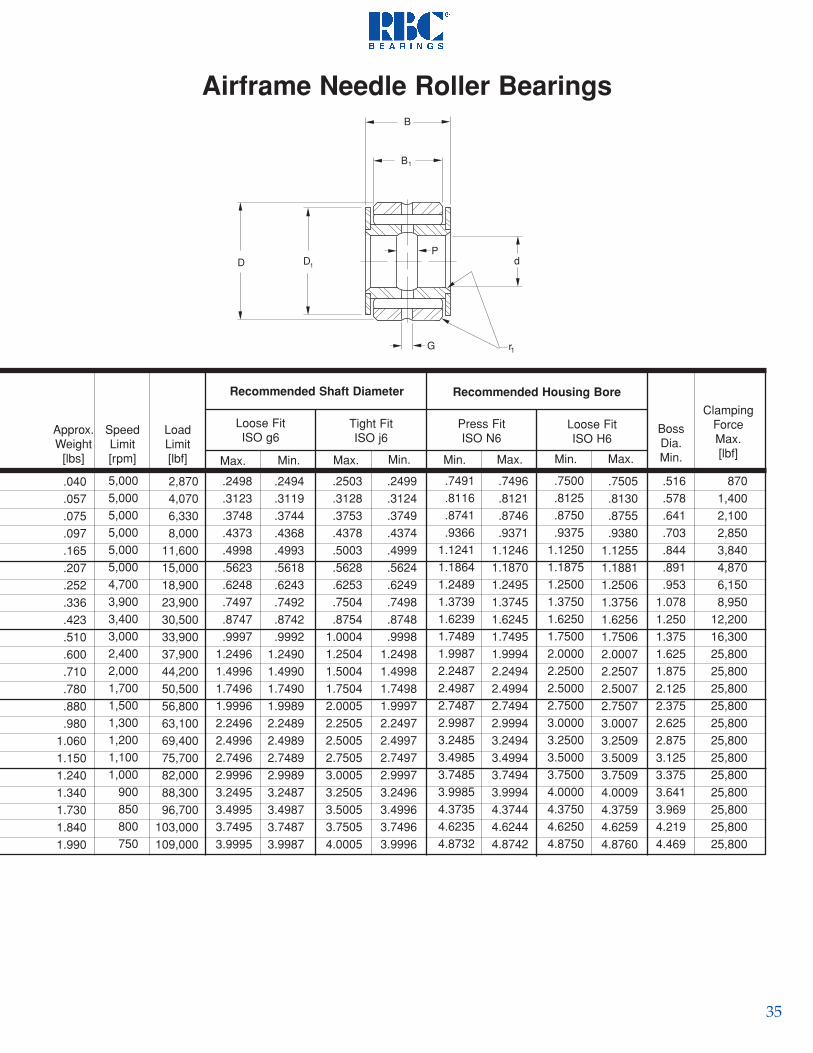
35
Airframe Needle Roller Bearings
ClampingForceMax.[lbf]
8701,4002,1002,8503,8404,8706,1508,950
12,20016,30025,80025,80025,80025,80025,80025,80025,80025,80025,80025,80025,80025,800
.516
.578
.641
.703
.844
.891
.9531.0781.2501.3751.6251.8752.1252.3752.6252.8753.1253.3753.6413.9694.2194.469
BossDia.Min.
.7496
.8121
.8746
.93711.12461.18701.24951.37451.62451.74951.99942.24942.49942.74942.99943.24943.49943.74943.99944.37444.62444.8742
.7491
.8116
.8741
.93661.12411.18641.24891.37391.62391.74891.99872.24872.49872.74872.99873.24853.49853.74853.99854.37354.62354.8732
.7505
.8130
.8755
.93801.12551.18811.25061.37561.62561.75062.00072.25072.50072.75073.00073.25093.50093.75094.00094.37594.62594.8760
.7500
.8125
.8750
.93751.12501.18751.25001.37501.62501.75002.00002.25002.50002.75003.00003.25003.50003.75004.00004.37504.62504.8750
.2499
.3124
.3749
.4374
.4999
.5624
.6249
.7498
.8748
.99981.24981.49981.74981.99972.24972.49972.74972.99973.24963.49963.74963.9996
.2503
.3128
.3753
.4378
.5003
.5628
.6253
.7504
.87541.00041.25041.50041.75042.00052.25052.50052.75053.00053.25053.50053.75054.0005
.2494
.3119
.3744
.4368
.4993
.5618
.6243
.7492
.8742
.99921.24901.49901.74901.99892.24892.49892.74892.99893.24873.49873.74873.9987
.2498
.3123
.3748
.4373
.4998
.5623
.6248
.7497
.8747
.99971.24961.49961.74961.99962.24962.49962.74962.99963.24953.49953.74953.9995
2,8704,0706,3308,000
11,60015,00018,90023,90030,50033,90037,90044,20050,50056,80063,10069,40075,70082,00088,30096,700
103,000109,000
5,0005,0005,0005,0005,0005,0004,7003,9003,4003,0002,4002,0001,7001,5001,3001,2001,1001,000
900850800750
SpeedLimit[rpm]
LoadLimit[lbf]
Loose FitISO g6
Tight FitISO j6
Recommended Shaft Diameter
Press FitISO N6
Loose FitISO H6
Recommended Housing Bore
.040
.057
.075
.097
.165
.207
.252
.336
.423
.510
.600
.710
.780
.880
.9801.0601.1501.2401.3401.7301.8401.990
Approx.Weight
[lbs]
P
B
D d
B1
G r1
D1
Max.Min.Max.Min.Min.Max.Min.Max.

36
Airframe Needle Roller Bearings
4 NBE 615 ZP5 NBE 717 ZP
6 NBK 919 YZP7 NBK 1021 YZP8 NBK 1224 YZP9 NBK 1427 YZP
10 NBK 1628 YZP12 NBK 1830 YZP14 NBK 2034 YZP16 NBK 2036 YZP20 NBK 2040 YZP24 NBK 2044 YZP32 NBK 2052 YZP40 NBK 2060 YZP48 NBK 2068 YZP56 NBK 2078 YZP
dInside Diameter
.053
.079
.130
.174
.293
.420
.520
.630
.870
.9601.0701.2301.4901.7802.0602.650
.094
.094
.125
.125
.125
.156
.156
.156
.156
.156
.156
.156
.156
.156
.156
.156
- -
.188
.188
.188
.188
.250
.250
.375
.375
.375
.375
.375
.375
.375
.375
.688
.750
.812
.8751.0311.0941.1561.2811.5001.6251.9062.1562.6563.1563.6564.219
.022
.022
.022
.032
.032
.032
.032
.032
.032
.032
.032
.032
.032
.032
.032
.044
.281
.344
.469
.531
.656
.781
.9061.0001.1251.1251.0491.0491.0491.0491.0491.049
.375
.437
.562
.625
.750
.8751.0001.1251.2501.2501.2501.2501.2501.2501.2501.250
.93701.0620
1.18701.31201.49951.68701.74951.87452.12442.24942.49942.74943.24923.74924.24924.8740
.93751.0625
1.18751.31251.50001.68751.75001.87502.12502.25002.50002.75003.25003.75004.25004.8750
.2493
.3118
.3743
.4368
.4993
.5618
.6243
.7493
.8743
.99931.24931.49931.99932.49932.99933.4992
.2500
.3125
.3750
.4375
.5000
.5625
.6250
.7500
.87501.00001.25001.50002.00002.50003.00003.5000
Max. Min.Nom. Max. Min.
DOutside Dia. Width
PART NUMBER B
Overall
r1
Shaft &Housing
FilletMax.
PInnerRing
GrooveWidth
GOuterRing
GrooveWidth
Approx.Weight
[lbs]
1/45/16
3/87/161/29/165/83/47/8
11 1/41 1/222 1/233 1/2
All dimensions are in inches
All exposed surfaces plated for corrosion resistance.
Series NBE
B
D
B1
Gr1
D1 d
D1
End PlateDia.
B1OuterRing

37
Airframe Needle Roller Bearings
8701,400
2,1002,8503,8404,8706,1508,950
12,20016,30025,80025,80025,80025,80025,80025,800
ClampingForceMax.[lbf]
5,0005,000
5,0005,0005,0005,0004,7004,0003,4003,0002,4002,0001,5001,2001,000
850
SpeedLimit[rpm]
Loose FitISO H6
Boss Diameter
Max. Min.Max.
Press FitISO N6
Recommended Housing Bore
Min.
Tight Transition FitISO j6
Max. Min. Max. Min.Min.Max.
LoadLimit[lbf]
2,8704,070
4,5305,8708,670
11,80015,50020,00025,80028,70031,40036,60047,10057,50067,90080,100
.2495
.3120
.3745
.4369
.4994
.5619
.6244
.7492
.8742
.99921.24901.49901.99882.49882.99883.4986
.2491
.3116
.3741
.4364
.4989
.5614
.6239
.7487
.8737
.99871.24841.49841.99812.49812.99813.4977
.2503
.3128
.3753
.4378
.5003
.5628
.6253
.7504
.87541.00041.25041.50042.00052.50053.00053.5005
Loose FitISO f6
Recommended Shaft Diameter
Series NBK
B
D
B1
Gr1
D1 dP
.2499
.3124
.3749
.4374
.4999
.5624
.6249
.7498
.8748
.99981.24981.49981.99972.49972.99973.4996
.93661.0616
1.18641.31141.49891.68641.74891.87392.12372.24872.49872.74873.24853.74854.24854.8732
.93711.0621
1.18701.31201.49951.68701.74951.87452.12442.24942.49942.74943.24943.74944.24944.8742
.93751.0625
1.18751.31251.50001.68751.75001.87502.12502.25002.50002.75003.25003.75004.25004.8750
.93801.0630
1.18811.31311.50061.68811.75061.87562.12572.25072.50072.75073.25093.75094.25094.8760
.688
.734
.781
.8441.0001.0621.0941.1561.3751.5001.7812.0622.5943.0623.5624.141
.516
.578
.641
.703
.844
.891
.9531.0781.2501.3751.6251.8752.3752.8753.3753.969

38
PART NUMBER
.125
.188
.188
.250
.250
.250
.375
.375
.375
.375
.375
.375
.375
.188
.250
.375
.375
.375
.375
.375
.375
.375
.375
.750
.9381.1881.3751.6251.8752.3752.8753.3123.7504.1884.6254.875
1.0001.2501.5001.7502.0002.1252.5002.7503.1883.625
D1
End PlateDia.
.022
.022
.032
.032
.032
.032
.032
.032
.032
.032
.032
.032
.032
.022
.032
.032
.032
.032
.032
.032
.032
.032
.032
r2
ShaftFilletMax.
.281
.375
.500
.625
.8751.0001.0491.2991.2991.2991.2991.2991.299
.8751.1251.3751.6251.8752.0492.2992.5492.7992.799
B1
OuterRing
.375
.500
.625
.7501.0001.1251.2501.5001.5001.5001.5001.5001.500
1.0001.2501.5001.7502.0002.2502.5002.7503.0003.000
B
Overall
Width
.87401.06151.31151.49901.74901.99992.49902.99903.43653.87404.31154.74904.9990
1.12401.37401.62401.87402.12402.37402.74902.99903.43653.8740
Min.
DOutside Diameter
.87501.06251.31251.50001.75002.00002.50003.00003.43753.87504.31254.75005.0000
1.12501.37501.62501.87502.12502.37502.75003.00003.43753.8750
Max.Min.
.2493
.3743
.4993
.6243
.7493
.87431.24931.49931.74931.99932.24932.49932.7493
.3743
.4993
.6243
.7493
.8743
.99931.24931.49931.74931.9993
.2500
.3750
.5000
.6250
.7500
.87501.25001.50001.75002.00002.25002.50002.7500
.3750
.5000
.6250
.7500
.87501.00001.25001.50001.75002.0000
Max.
1/43/81/25/83/47/8
1 1/41 1/21 3/422 1/42 1/22 3/4
3/81/25/83/47/811 1/41 1/21 3/42
Nom.
dInside Diameter
4 NBF 614 YJ6 NBF 817 YJ8 NBF 1021 YJ
10 NBF 1224 YJ12 NBF 1628 YJ14 NBF 1832 YJ20 NBF 2040 YJ24 NBF 2448 YJ28 NBF 2455 YJ32 NBF 2462 YJ36 NBF 2469 YJ40 NBF 2476 YJ44 NBF 2480 YJ
6 NBL 1618 YJ8 NBL 2022 YJ
10 NBL 2426 YJ12 NBL 2830 YJ14 NBL 3234 YJ16 NBL 3638 YJ20 NBL 4044 YJ24 NBL 4448 YJ28 NBL 4855 YJ32 NBL 4862 YJ
Series NBF
B
D
B1
P
r2
D1 d
T
PInner Ring
GrooveWidth
Airframe Track Rollers
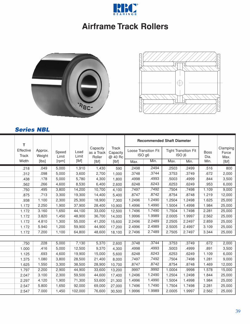
39
Airframe Track Rollers
8002,0003,5006,0009,000
12,00025,00025,00025,00025,00025,00025,00025,000
2,0003,5006,0009,000
12,00015,00025,00025,00025,00025,000
ClampingForceMax.[lbf]
.516
.672
.844
.9531.1091.2191.6251.9842.2812.5622.8593.1093.344
.672
.8911.1091.2811.4691.5781.8441.9842.2812.562
BossDia.Min.
.2499
.3749
.4999
.6249
.7498
.87481.24981.49981.74981.99972.24972.49972.7497
.3749
.4999
.6249
.7498
.8748
.99981.24981.49981.74981.9997
Min.
Tight Transition FitISO j6
Recommended Shaft Diameter
.2503
.3753
.5003
.6253
.7504
.87541.25041.50041.75042.00052.25052.50052.7505
.3753
.5003
.6253
.7504
.87541.00041.25041.50041.75042.0005
Max.Min.
.2498
.3748
.4998
.6248
.7497
.87471.24961.49961.74961.99962.24962.49962.7496
.3748
.4998
.6248
.7497
.8747
.99971.24961.49961.74961.9996
Max.
Loose Transition FitISO g6
5901,0001,8002,6004,1005,4007,300
10,90012,50014,00015,60017,20018,100
2,6004,3005,6008,000
10,70013,20017,40021,30027,00030,500
TrackCapacity@ 40 Rc
[lbf]
LoadLimit[lbf]
1,9103,6005,7808,530
14,20019,30025,30037,90044,10048,90055,00059,90064,800
7,13012,50019,90028,50038,50044,90059,50071,30092,000
102,000
5,0005,0005,0004,6003,8003,3002,3001,9001,6501,4501,3001,2001,100
5,0005,0004,6003,8003,3002,9002,3001,9001,6501,450
SpeedLimit[rpm]
Approx.Weight
[lbs]
.049
.098
.178
.266
.495
.7131.1002.2503.1603.8204.8105.9407.200
.228
.416
.6931.0801.5502.2003.1004.1205.8007.000
Capacityas a Track
Roller[lbf]
TEffective
TrackWidth
.218
.312
.438
.562
.750
.875
.9381.1721.1721.1721.1721.1721.172
.7501.0001.1251.3751.6251.7972.0472.2972.5472.547
Series NBL
1,4302,7004,3006,400
10,70014,40018,90028,40033,00036,70041,20044,90048,600
5,3709,370
15,00021,40028,90033,60044,60053,60069,00076,600
.2494
.3744
.4993
.6243
.7492
.87421.24901.49901.74901.99892.24892.49892.7489
.3744
.4993
.6243
.7492
.8742
.99921.24901.49901.74901.9989

40
TECHNICAL DATA
the outer ring around the point of contact. The effectsare outer ring deformation with reversed bendingstresses in dynamic applications, a reduced load zone, and a higher maximum roller load (see Fig. 1.).
To keep deformation to a minimum, the outer ring ofa cam follower must have a considerably heavier cross section than a standard bearing. This require-ment conflicts with the desire for maximum dynamicbearing capacity which needs as large a roller diame-ter as possible. RBC cam followers and yoke rollersprovide an optimum compromise between outer ringstrength and theoretical bearing capacity.
2. Capacity and Load Limits
Evaluation of the expected service life and limit loadsof cam followers is more complex than with housedbearings. In addition to the static and dynamic capacityof the rolling elements, outer ring deformation, track capacity, and cam follower stud bending stress must beconsidered. In yoke rollers, the pin shear stress must beconsidered.
RBC lists the static bearing capacity for referencepurposes only. Typically, the maximum allowable loadis a function of the maximum permissible bendingstress of the stud or the outer ring. For best results, theoperating loads should not exceed the lower of trackcapacity or 50% of the dynamic capacity.
2.1 Capacity of Rolling Element Bearing
Equations for static and dynamic capacities of rollerbearings are given in ANSI/ABMA Standard 11. Themore recent revisions leave it up to the manufacturer tointroduce factors which account for internal design features and operating conditions. For cam followersand yoke rollers RBC has chosen to apply a conservativerating system, so a direct comparison with capacity figures of competitive products may not be possible.
2.2 Track Capacity
Cam Followers, Yoke, and Track Rollers
Introduction to Cam Follower Technology
Safety Precaution
In rare cases a bearing failure may cause great mechani-cal damage or even lead to personal injury. To help pre-vent such losses, you may contact RBC’s engineeringstaff to review your application details. The engineeringstaff’s review will assist you in identifying potential prob-lem areas and suggest modifications to improve bearingperformance in your application. The engineering staff atRBC has many years of experience with a large variety ofapplications and operating conditions. If you have a safetyrelated application and would like an evaluation by RBC’sengineering department, please submit your applicationdetails in confidence.
1. Difference from Standard Bearings
The outer rings of regular ball and roller bearingsare typically mounted in rigid housings providingsupport around the entire circumference. Individualroller forces are transmitted through the outer ringdirectly into the housing with no major deformations.
By contrast, cam followers and yoke rollers are supported at a single point on their circumference.Individual roller forces produce bending moments on
Fig. 1
Load Zone & Maximum Contact Stress
Deformed Outer Ring
Load ZoneRigidly Supported
Outer Ring
Contact Stress ProfileDeformed Outer Ring
Rigidly SupportedOuter Ring
Contact Stress ProfileRigidly Supported
Outer Ring
Load ZoneDeformed Outer Ring
Track capacity is that load which a track subject to auniform contact stress can withstand without excessiveplastic deformation. It is directly related to track hard-ness. The published track capacity is based on a hardnessof HRc 40. For other track hardness values the trackcapacity must be modified with factors from Table 1.

41
where
2.3. Bending and Shear Stresses
2.3.1 Cam Follower Stud Bending Stress
If the load over the width of the outer ring isevenly distributed, it may be replaced by a singleconcentrated force F [lbf] acting at the center of thecam follower (see Fig.2). Assuming that the cam follower stud has been tightly mounted in a housingbore flush with the end plate, this concentrated forcegenerates a bending moment Mb.
where B = outer ring width [in]1/32 = cam follower overhang [in]
The bending moment generates a bending stressin the cam follower stud of approximate magnitude
where SD=Stud Diameter [in]
Standard cam follower studs are heat treated to ahardness of HRc 58 min in the raceway area only.
Fig. 2
Table 1. Track Capacity Adjustment Factors.
Alternatively, contact stress can be easily calcu-lated and compared directly to the strength of mate-rial. The equation for the Hertz contact stress be-tween a cylindrical cam follower outer ring and a flatsteel track is given by “Roark, Formulas for Stressand Strain” as:
F = radial load [lbf]leff = length of outer ring contact [in]D = outer ring diameter [in]
It can be shown that for infinite life the ultimatetensile strength of track and roller must be at leastequal to the maximum contact stress
Example 1:
Determine the required minimum track hardnessfor an RBC cam follower S 56 L operating under a3000 lbf radial load.
Solution:
(1)[psi]
σC max
σ = 3,237C max
3,000 lbf0.8 in 1.75 in*
* = 149,800 psi
σ = 3,237C max
FI D*eff
*
(2)M = Fb *B2
+ 132( ) [in lbf]*
(3)σ = 10b *M
SD3
b [psi]
1/32*
F
B
Moment Arm
Track
Housing
Theoretical Moment Armwithout stud deflection
*sizes 160 and above = 1/16
Track Hardness Material Strength Modification[HRc] [psi] Factor
26 128,000 .4532 146,000 .6136 165,000 .7940 182,000 1.0044 204,000 1.2447 229,000 1.5050 247,000 1.7853 266,000 2.0956 281,000 2.4258 298,000 2.78
Referring to Table 1, 149,800 psi is between 146,000 psi(HRc32) and 165,000 (HRc 36). Interpolation yields aminimum track hardness of HRc 33.
42
The hardness in other areas of the stud is typically in arange of HRc 20 -22 with an ultimate strength of material of 110,000 -120,000 psi. RBC bases the maxi-mum allowable load of stud type cam followers on atheoretical stud bending stress of 100,000 psi. Stan-dard stud cam followers and heavy stud cam follow-ers differ in stud diameter, which permits higher operating loads and more resistance to impact load-ing for the heavy stud version. High stud strengthcam followers are available by special order.
In most applications the stud will deflect awayfrom the load, which causes the point of attack to shift toward the support, shortening the moment arm and reducing the effective bending moment (seeFig. 3). Tests show that this deflection yields a safetyfactor of at least 2 over RBC’s maximum allowableload. However, this effect may not be sufficient toavoid damage in severely misaligned applicationswhere the load is applied at the very extreme out-board edge of the cam follower outer ring.
Where misalignment is a problem, RBC recom-mends crowned cam followers.
Example 2Cam follower S 64 L supports a load of 6,000 lbf.The stud diameter is .875", the outer ring width 1.25".Determine the theoretical bending stress at the studhousing interface.
Solution:
Fig. 3
2.3.2 Yoke Roller Pin Shear Stress
Yoke rollers are mounted with a pin in a yoke.Under load the pin is subject to shear and bendingstresses. RBC recommends that the yoke arms arelocated as close to the yoke roller as possible, so thatbending stress can be ignored. In case of widelyspaced pin supports, the resulting pin deflection maycause yoke roller damage.
The pin shear stress can be calculated with
where d=pin diameter
The permissible stress depends on the pin materialselection.
Example 3Determine the shear stress of the .375 in. diameter pinfor yoke roller Y 40 L, loaded radially with 3,200 lbf.
Solution:
2.4 Outer Ring Stress and Deformation
The exact calculation of these values is beyond thescope of this introduction. The following methodmay be used for a (high) first estimate of the outerring tensile stress at the inside diameter opposite thecontact point of a single row cam or roller follower.The assumption is that the entire load is supported byonly 2 rollers straddling the point of contact:
where F = cam follower load [lbf]Di = outer ring raceway diameter [in]D = outer ring outside diameter [in]z = number of rollers per row b = idealized outer ring width [in]σ = 10b
3,938 in lbf(.875 in)* = 58,776 psi
(M = 6,000 lbfb *1.25 in
2+ 1
32 )in = 3,938 in lbf*
*3
σ = 2S
Fπ d*
*2 (4)[psi]
(5)[psi]z b (D - D )
σ =b max6 F D π** i
* **
2i
σ = 2S
3,200 lbfπ (.375 in)*
*2 = 14,487 psi
F
Effective Moment Arm
Effective Moment Armwith stud deflection
Theoretical Moment Arm

43
In case of constant load, the equivalent radial loadequals the constant load. To compute the equivalentload for all other cases, use:
(9)
where q = 10/3 for roller bearingsFt = individual radial load [lbf]
4. Speed Limit and Maximum Acceleration
4.1 Speed Limit
The limiting speed of rolling element bearings isprimarily a function of size and internal design. Thespeed limits given in this catalog should not beexceeded on a continuous basis to prevent prematurefailure due to excessive temperature. Contact RBC forsolutions to high speed applications.
4.2 Maximum Acceleration (Deceleration)
A sufficiently large tangential friction force Ft , acting between outside diameter and track is neededto change the rotational speed of cam follower andyoke roller outer rings.
(10)
where µ = coefficient of friction(outer ring to track)
The force Ft produces a moment Mt, which mustaccelerate the masses of outer ring and rollers aroundthe bearing axis, plus the rollers in the load zonearound their own axes.
Example 4 Estimate the outer ring tensile stress of yoke roller Y 56 L subject to a load of 6,000 lbf. The yoke rollerhas 25 rollers, the outer ring outside diameter = 1.750in., the outer ring raceway diameter =1.125 in., theidealized outer ring width = .690 in.
Solution:
3. Fatigue Life
Fatigue life, L10 [rev, hrs], is a statistical measure of
the life which 90% of a large group of apparently iden-tical rolling element bearings will complete or exceed.For a single bearing, L10 also refers to the life associat-
ed with 90% reliability.
The relationship between fatigue or rating life, capacityand load is:
(6)
where L10 rev = Rating life [106 rev]C = Dynamic capacity [lbf]Pe = Equivalent radial load
To obtain the rating life in hours, use
(7)
L10 hrs = Rating life [hours]where ne = equivalent speed [rpm]
In case of constant speed, the equivalent speed equalsthe constant bearing speed. In all other cases theequivalent speed is the weighted average of all indi-vidual speed components.
(8)
where ni = individual speed component [rpm]ti = time interval in percent of total time
25 .690 in (1.75 in - 1.125 in )σ =b max
6 6,000 lbf 1.125 π**
* **
2 = 18,880 psi
)(L =10 revCP
103
e
L =10 hrs )(CP
103
e
16,667ne
*
n =e )(n t100i i* =
n t1001 1* +
n t1002 2* + ...Σ
n 100
P=e )(F n ti i* =Σ i*
q
e *
q
n 100F n t1 1* 1*
q
e *
q + + ...
n 100F n t2 2* 2*
q
e *
F = F µ [lbf]t *

44
RBC offers a convenient socket (W suffix) for hexwrenches to provide a more substantial grip, espe-cially for ‘blind hole’ applications.
5.2 Eccentric Cam Followers
Eccentric cam followers are used when there is aneed to make height adjustments between the cam follower and the track. By simply turning the entirecam follower inside the housing it is possible to adjust the distance between the cam follower and thetrack by twice the eccentricity. However, due to themechanical advantage that the eccentricity provides, it is inadvisable that the cam follower be adjusted over this entire range.
A very large force can be exerted on the track for asmall applied adjusting torque as the eccentricity ofthe cam follower approaches ±90 degrees from a starting position parallel to the track, in the housing.Adjustments should be limited to ±45 degrees and the resulting preload should not exceed 10% of thecam follower’s capacity.
The following equation can be used to find anappropriate adjusting torque.
T = 0.1 * C * e * cos 45° [in * lbf]
where T = appropriate adjusting torque [lbf]C = cam followers dynamic capacity [lbf]
e = eccentricity of cam follower [in]
Example 5CamCentric cam follower S48LWX has a dynamiccapacity of 4,600 lb, and an eccentricity of 0.03 in.Determine the appropriate adjusting torque.
Solution: T = 4,600 lbf * 0.03 in * 0.070711 = 9.76 in * lbf
The moment Mt can be calculated using:
Accelerating the mass of the outer ring normally requires the largest part of moment Mt. Assuming
a coefficient of friction of µ = 0.10 and a typical cam follower design, the following equation may be used foran estimate of the permissible angular acceleration α:
(12)
Excessive acceleration causes sliding of the outerring on the track. The effects range from minor uniform wear on cam follower and track to flat spotson the cam follower with subsequent failure.
5. Mounting
5.1 Cam Followers
For greatest rigidity and strength, the end plateshould be drawn up snugly against a boss or otherflat surface of the housing. The tables on pages 8throughout 23 list the maximum recommendedclamping torque for lubricated threads, which is thenormal condition. Use up to twice the listed torquefor completely dry threads.
The housing bore should be drilled and reamed tothe recommended tolerance. If a greater tolerance isneeded, it should be added to the plus side to preventcam follower damage during assembly. If the cam follower stud fits tightly into the housing bore, use anarbor press and apply pressure against the centralportion of the flange. Never press against the rim ofthe flange or the outer ring.
Although wide blade screwdrivers may be used tohold slotted head cam followers during assembly,rounded tools conforming to the slot are preferable toavoid plastic deformation in the slot area.
M = [in lbf]D F
t* t2 *
α = [rad/sec ]6000 M
perm* t
B D*
24
(11)
(13)
Fig. 4
(14)
�
�θ

45
cam followers require relubrication depending on operating speed, duty cycle, operatingenvironment, desired service life, etc.
For relubrication in service, mineral oil, or any goodroller bearing grease on mineral oil basis may be used.Inquire about compatibility of greases with differentbase oil and thickener.
Except for the very small sizes (see tables), cam followers with screwdriver slots can be relubricatedfrom both ends of the stud and through the housing.Table 2 lists suitable drive fit Alemite fittings. Plugs are furnished by RBC to close off unused passages.
Table 2. Alemite fittings.Cam followers of the HexLube® series are supplied
5.3 Yoke Rollers
RBC yoke rollers correspond in many respects to thesame size cam follower, except they are mounted on apin for use in yoke type applications for greater shock resistance.
Yoke rollers should be clamped axially or mountedwithin closely fitting side rails to prevent displacementof the end plates. For applications with heavy loads, it is recommended to heat treat the pin and use a press fitfor the inner ring. A soft pin and light press or push fitare sufficient for lightly loaded applications. When press fitting a yoke roller, pressure should be appliedcentrally and uniformly against the end plate, neveragainst the outer ring.
The pin should have a suitable lead-in chamfer orradius to prevent scoring and to hold the mountingforce to a minimum.
5.4 Caged Roller Followers
Caged roller followers can operate directly on a hard-ened and ground shaft (HRc 58 min, 16 rms min surfacefinish) or can be used with matching inner rings. Operat-ing without an inner ring yields the largest possible shaftdiameter with greatest strength and rigidity. Axial guidance must be provided by the application. It is recommended to use hardened steel or bronze thrustwashers with radial lubricating grooves as needed.
6.1 Track Lubrication
In most applications it is difficult to eliminate all camfollower misalignment. Misalignment causes the outerring to thrust, which in needle bearing cam followers,produces wear of the seal followed by wear of the outerring face and the stud flange or the end plate. In RBCRollers ® the wear is generallly limited to the center thrustring. Misalignment where the axis of the cam follower isnot perpendicular to the direction of rolling, typicallyproduces the most severe thrust and also causes wear onthe cam follower outside diameter, and the track. Toreduce these symptoms as much as possible, the trackmust be lubricated. Lubrication also reduces wear stem-ming from excessive acceleration. Oil and grease areacceptable lubricants.
If the track cannot be lubricated, contact RBC Engineer-ing for a review of the operating parameters to ensure thatthey do not exceed the limits of the bearing selected.
6.2 Bearing Lubrication
Cam followers and yoke rollers are pre-lubricatedwith an NLGI grade 2, lithium soap, mineral oil basedgrease with EP additives. RBC Roller® type cam follow-ers and yoke rollers are normally lubricated for life andhave no provisions for relubrication. Needle roller type
Size Bearing P/N Fitting P/N
1/2" - 11/16" -16 to -22 30193/4" - 2 3/4" -24 to -88 1728-B, 1646-B, 1992-B3" - 4" -96 to -128 1743, 1743-B5" - up -160 any 1/4" NPT fitting
with a grease fitting at the bottom of the hex hole. Yokerollers and sealed roller followers must be relubricatedthrough the shaft.
7. Misalignment
Initial misalignment should not exceed .001 in./in.Any misalignment generates thrust forces between outerring and flange or end plate. Excessive thrusting can leadto increased operating temperature and destruction of theseal in standard cam followers and yoke rollers. Wheremisalignment and outer ring thrusting cannot be avoided,RBC recommends crowned outer rings or the RBC Roller®
design which is more capable of withstanding thrust loads. Contact RBC engineers about thrust and load limits.
8. Operating Temperature
The temperature limits of all standard cam followersand yoke rollers in this catalog, except airframe bearings,are determined by the temperature limits of the seals andthe lubricant. With lower temperatures, grease graduallybecomes stiffer, increasing the rolling resistance of thecam follower. Any application with the cam followeroperating continuously below 0° F (-18° C), consult withRBC Engineering for a specific low temperature grease.The maximum continuous operating temperature is+250° F (120° C), and for short periods, the maximumtemperature may rise to +300° F (150° C). For continuousoperation above +250° F (120° C), consult with RBCEngineering to determine the need for special high tem-perature grease and seal material.
RBC can provide special solutions for applicationsoutside the normal operating temperature range.

46
TYPICAL APPLICATIONS
Material Handling EquipmentCarriage rollers and side rollers of lift trucks are typicalapplications where roller followers have performed exceed-ingly well. The heavy walled outer ring eliminates the needfor a separate tire and bearing assembly.
Drum CamA pair of heavy stud cam followers are shown mounted inlinkages activated by a drum cam or grooved rotating shaft.A lubrication hole through the stud accepts a drive fittingfor periodic relubrication.
Rewind StandsRewind stands for packaging material or printed coils makeuse of cam followers. A simple two or three point supportconsists simply of several cam followers acting on the journalor body of the roll. The upper bracket is optional and a veryquick changeover results in either case.
46

47
Table SupportsYoke rollers may be effectively mounted to support tables,tracks or other machine members requiring linear motion.The illustration depicts horizontal location between yokerollers, but this may be achieved by cam followers or Cam-
Centric® followers as well.
Turntable MountingCam followers can be mounted in a circular housing tosupport a ring or thrust plate. Precise leveling adjustmentfor the turntable can be obtained using the adjustableCamCentric® cam follower.
Internal Combustion EnginesRBC's yoke roller followers have found wide acceptance asvalve tappet and fuel injection rollers. The outer ringflanges support the cage against high inertia loads assuringpositive, individual roller control by the cage.
TYPICAL APPLICATIONS
47

4848
TYPICAL APPLICATIONSCluster MountingCluster mounting of four cam followers around a squarecolumn demonstrates the unique versatility of these bearings.Threads are concentric with the shank within very close limits. This feature is important on “blind hole” mountingswhere run-out would result in binding.
Manual Lift TruckSchematic arrangement of cam followers is shown on theupright of a warehouse hand truck. CamCentric® bearingsare frequently used to provide adjustment so that all bearingscontact the track without critical hole positioning.
Textile MachineryThe sealed yoke rollers work extremely well as picking rollsof looms due to the fact that the minimum friction assuresconstant turning to eliminate wear.

4949
UNIVERSAL SERIES™ INTERCHANGE TABLES
McGill
CF-1/2-SBCF-9/16-SBCF-5/8-SBCF-11/16-SBCF-3/4-SBCF-7/8-SBCF-1-SBCF-1 1/8-SBCF-1 1/4-SBCF-1 3/8-SBCF-1 1/2-SBCF-1 5/8-SBCF-1 3/4-SBCF-1 7/8-SBCF-2 -SBCF-2 1/4-SBCF-2 1/2-SBCF-2 3/4-SBCF-3 -SBCF-3 1/4-SBCF-3 1/2-SBCF-4 -SBCF-5 -SBCF-6 -SB
Torrington
CRSB-8-1—
CRSB-10-1—
CRSB-12CRSB-14CRSB-16CRSB-18CRSB-20CRSB-22CRSB-24CRSB-26CRSB-28CRSB-30CRSB-32CRSB-36CRSB-40CRSB-44CRSB-48CRSB-52CRSB-56CRSB-64CRSB-80CRSB-96
S16LS18LS20LS22LS24LS28LS32LS36LS40LS44LS48LS52LS56LS60LS64LS72LS80LS88LS96LS104LS112LS128LS160LS192L
CF-1/2CF-9/16CF-5/8CF-1 1/16CF-3/4CF-7/8CF-1CF-1 1/8CF-1 1/4CF-1 3/8CF-1 1/2CF-1 5/8CF-1 3/4CF-1 7/8CF-2CF-2 1/4CF-2 1/2CF-2 3/4CF-3CF-3 1/4CF-3 1/2CF-4CF-5CF-6
CF-1/2-SCF-9/16-SCF-5/8-SCF-1 1/16-SCF-3/4-SCF-7/8-SCF-1-SCF-1 1/8-SCF-1 1/4-SCF-1 3/8-SCF-1 1/2-SCF-1 5/8-SCF-1 3/4-SCF-1 7/8-SCF-2-SCF-2 1/4-SCF-2 1/2-SCF-2 3/4-SCF-3-SCF-3 1/4-SCF-3 1/2-SCF-4-SCF-5-SCF-6-S
CR-8-1N/A
CR-10-1N/A
CR-12CR-14CR-16CR-18CR-20CR-22CR-24CR-26CR-28CR-30CR-32CR-36CR-40CR-44CR-48CR-52CR-56CR-64CR-80CR-96
CRS-8-1N/A
CRS-10-1N/A
CRS-12CRS-14CRS-16CRS-18CRS-20CRS-22CRS-24CRS-26CRS-28CRS-30CRS-32CRS-36CRS-40CRS-44CRS-48CRS-52CRS-56CRS-64CRS-80CRS-96
McGillRBC Part No.
S16LW*S18LW*S20LW*S22LW*S24LWS28LWS32LWS36LWS40LWS44LWS48LWS52LWS56LWS60LWS64LWS72LWS80LWS88LWS96LWS104LWS112LWS128LWS160LWS192LW
RBC UUNNIIVVEERRSSAALLHexLube® Series
REPLACESDirect Interchange
RBC Torrington
STANDARD STUDWith Hex Socket Head — Sealed
REPLACES
*Cannot be lubricated through hexhead
S16S18S20S22S24S28S32S36S40S44S48S52S56S60S64S72S80S88S96S104S112S128S160S192

50
RBC Part No.
CS16LW*CS18LW*CS20LW*CS22LW*CS24LWCS28LWCS32LWCS36LWCS40LWCS44LWCS48LWCS52LWCS56LWCS60LWCS64LWCS72LWCS80LWCS88LWCS96LWCS104LWCS112LWCS128LWCS160LWCS192LW
RBC UUNNIIVVEERRSSAALLHexLube® Series
REPLACES
McGill
CCF-1/2-SBCCF-9/16-SBCCF-5/8-SBCCF-11/16-SBCCF-3/4-SBCCF-7/8-SBCCF-1-SBCCF-1 1/8-SBCCF-1 1/4-SBCCF-1 3/8-SBCCF-1 1/2-SBCCF-1 5/8-SBCCF-1 3/4-SBCCF-1 7/8-SBCCF-2-SBCCF-2 1/4-SBCCF-2 1/2-SBCCF-2 3/4-SBCCF-3-SBCCF-3 1/4-SBCCF-3 1/2-SBCCF-4-SBCCF-5-SBCCF-6-SB
Torrington
CRSBC-8-1—
CRSBC-10-1—
CRSBC-12CRSBC-14CRSBC-16CRSBC-18CRSBC-20CRSBC-22CRSBC-24CRSBC-26CRSBC-28CRSBC-30CRSBC-32CRSBC-36CRSBC-40CRSBC-44CRSBC-48CRSBC-52CRSBC-56CRSBC-64
——
CS16LCS18LCS20LCS22LCS24LCS28LCS32LCS36LCS40LCS44LCS48LCS52LCS56LCS60LCS64LCS72LCS80LCS88LCS96LCS104LCS112LCS128LCS160LCS192L
RBC
CCF-1/2-SCCF-9/16-SCCF-5/8-SCCF-11/16-SCCF-3/4-SCCF-7/8-SCCF-1-SCCF-1 1/8-SCCF-1 1/4-SCCF-1 3/8-SCCF-1 1/2-SCCF-1 5/8-SCCF-1 3/4-SCCF-1 7/8-SCCF-2-SCCF-2 1/4-SCCF-2 1/2-SCCF-2 3/4-SCCF-3SCCF3 1/4-SCCF-3 1/2-SCCF-4-SCCF-5-SCCF-6-S
McGill
CRSC-8-1N/A
CRSC-10-1N/A
CRSC-12CRSC-14CRSC-16CRSC-18CRSC-20CRSC-22CRSC-24CRSC-26CRSC-28CRSC-30CRSC-32CRSC-36CRSC-40CRSC-44CRSC-48CRSC-52CRSC-56CRSC-64
——
Torrington
STANDARD STUDWith Crowned Outer — Sealed—Hex Head
REPLACESDirect Interchange
*Cannot be lubricated through hexhead
UNIVERSAL SERIES™ INTERCHANGE TABLES
50

51
UNIVERSAL SERIES™ INTERCHANGE TABLES
STANDARD STUDWith Hex Socket Head
Eccentric Bushing — Sealed
McGill
CFE-1/2-SBCFE-9/16-SBCFE-5/8-SBCFE-11/16-SBCFE-3/4-SBCFE-7/8-SBCFE-1-SBCFE-1 1/8-SBCFE-1 1/4-SBCFE-1 3/8-SBCFE-1 1/2-SBCFE-1 5/8-SBCFE-1 3/4-SBCFE-1 7/8-SBCFE-2 -SBCFE-2 1/4-SBCFE-2 1/2-SBCFE-2 3/4-SBCFE-3 -SBCFE-3 1/4-SBCFE-3 1/2-SBCFE-4 -SB
Torrington
CRSBE-8-1—
CRSBE-10-1—
CRSBE-12CRSBE-14CRSBE-16CRSBE-18CRSBE-20CRSBE-22CRSBE-24CRSBE-26CRSBE-28CRSBE-30CRSBE-32CRSBE-36CRSBE-40CRSBE-44CRSBE-48CRSBE-52CRSBE-56CRSBE-64
RBC Part No.
S16LWXS18LWXS20LWXS22LWXS24LWXS28LWXS32LWXS36LWXS40LWXS44LWXS48LWXS52LWXS56LWXS60LWXS64LWXS72LWXS80LWXS88LWXS96LWXS104LWXS112LWXS128LWX
RBC UUNNIIVVEERRSSAALLHexLube® Series
REPLACESDirect Interchange
RBC Part No.
CS16LWXCS18LWXCS20LWXCS22LWXCS24LWXCS28LWXCS32LWXCS36LWXCS40LWXCS44LWXCS48LWXCS52LWXCS56LWXCS60LWXCS64LWXCS72LWXCS80LWXCS88LWXCS96LWXCS104LWXCS112LWXCS128LWX
RBC UUNNIIVVEERRSSAALLHexLube® Series
REPLACESDirect Interchange
McGill
CCFE-1/2-SBCCFE-9/16-SBCCFE-5/8-SBCCFE-11/16-SBCCFE-3/4-SBCCFE-7/8-SBCCFE-1-SBCCFE-1 1/8-SBCCFE-1 1/4-SBCCFE-1 3/8-SBCCFE-1 1/2-SBCCFE-1 5/8-SBCCFE-1 3/4-SBCCFE-1 7/8-SBCCFE-2-SBCCFE-2 1/4-SBCCFE-2 1/2-SBCCFE-2 3/4-SBCCFE-3-SBCCFE-3 1/4-SBCCFE-3 1/2-SBCCFE-4-SB
Torrington
CRSBCE-8-1—
CRSBCE-10-1—
CRSBCE-12CRSBCE-14CRSBCE-16CRSBCE-18CRSBCE-20CRSBCE-22CRSBCE-24CRSBCE-26CRSBCE-28CRSBCE-30CRSBCE-32CRSBCE-36CRSBCE-40CRSBCE-44CRSBCE-48CRSBCE-52CRSBCE-56CRSBCE-64
STANDARD STUDWith Hex Socket Head
Crowned OuterEccentric Bushing —Sealed
51

52
HEAVY STUDWith Hex Socket Head — Sealed
RBC Part No.
CH16LWCH18LWCH20LWCH22LWCH24LWCH28LWCH32LWCH36LWCH40LWCH44LWCH48LWCH52LWCH56LWCH60LWCH64LWCH72LWCH80LWCH88LWCH96LWCH104LWCH112LWCH128LWCH160LWCH192LW
RBC UUNNIIVVEERRSSAALLHexLube® Series
REPLACESDirect Interchange
REPLACES
McGill
CCFH-1/2-SBCCFH-9/16-SBCCFH-5/8-SBCCFH-11/16-SBCCFH-3/4-SBCCFH-7/8-SBCCFH-1-SBCCFH-1 1/8-SBCCFH-1 1/4-SBCCFH-1 3/8-SBCCFH-1 1/2-SBCCFH-1 5/8-SBCCFH-1 3/4-SBCCFH-1 7/8-SBCCFH-2-SBCCFH-2 1/4-SBCCFH-2 1/2-SBCCFH-2 3/4-SBCCFH-3-SBCCFH-3 1/4-SBCCFH-3 1/2-SBCCFH-4-SBCCFH-5-SBCCFH-6-SB
CH16LCH18LCH20LCH22LCH24LCH28LCH32LCH36LCH40LCH44LCH48LCH52LCH56LCH60LCH64LCH72LCH80LCH88LCH96LCH104LCH112LCH128LCH160LCH192L
RBC McGill Torrington
N/AN/A
CRHSC-10-1N/A
CRHSC-12N/A
CRHSC-16CRHSC-18CRHSC-20
N/AN/AN/A
CRHSC-28N/A
CRHSC-32N/A
CRHSC-40N/A
CRHSC-48N/AN/AN/AN/AN/A
HEAVY STUDWith Crowned Outer — Sealed—Hex Head
H16H18H20H22H24H28H32H36H40H44H48H52H56H60H64H72H80H88H96H104H112H128N/AN/AN/A
CFH-1/2-SCFH-9/16-SCFH-5/8-SCFH-11/16-SCFH-3/4S-SCFH-7/8S-SCFH-1S-SCFH-1 1/8-SCFH-1 1/4-SCFH-1 3/8-SCFH-1 1/2-SCFH-1 5/8-SCFH-1 3/4-SCFH-1 7/8-SCFH-2-SCFH-2 1/4-SCFH-2 1/2-SCFH-2 3/4-SCFH-3-SCFH-3 1/4-SCFH-3 1/2-SCFH-4S
N/AN/AN/A
McGillRBC Part No.
H16LW*H18LW*H20LW*H22LW*H24LWH28LWH32LWH36LWH40LWH44LWH48LWH52LWH56LWH60LWH64LWH72LWH80LWH88LWH96LWH104LWH112LWH128LWH160LWH192LWH224LW
RBC UUNNIIVVEERRSSAALLHexLube® Series
REPLACESDirect Interchange
RBC
REPLACES
Torrington TorringtonMcGill
CFH-1/2-SBCFH-9/16-SBCFH-5/8-SBCFH-11/16-SBCFH-3/4-SBCFH-7/8-SBCFH-1-SBCFH-1 1/8-SBCFH-1 1/4-SBCFH-1 3/8-SBCFH-1 1/2-SBCFH-1 5/8-SBCFH-1 3/4-SBCFH-1 7/8-SBCFH-2 -SBCFH-2 1/4-SBCFH-2 1/2-SBCFH-2 3/4-SBCFH-3 -SBCFH-3 1/4-SBCFH-3 1/2-SBCFH-4 -SBCFH-5 -SBCFH-6 -SBCFH-7 -SB
H16LH18LH20LH22LH24LHS28LHS32LHS36LHS40LHS44LHS48LHS52LHS56LHS60LHS64LHS72LH80LH88LH96LH104LH112LH128N/AN/AN/A
CFH-1/2CFH-9/16CFH-5/8CFH-11/16CFH-3/4CFH-7/8CFH-1CFH-1 1/8CFH-1 1/4CFH-1 3/8CFH-1 1/2CFH-1 5/8CFH-1 3/4CFH-1 7/8CFH-2CFH-2 1/4CFH-2 1/2CFH-2 3/4CFH-3CFH-3 1/4CFH-3 1/2CFH-4
N/AN/AN/A
Torrington
N/AN/AN/AN/AN/AN/AN/AN/AN/AN/AN/AN/AN/AN/AN/AN/AN/AN/AN/AN/AN/AN/AN/AN/A
CCFH-1/2-SCCFH-9/16-SCCFH-5/8-SCCFH-11/16-SCCFH-3/4-SCCFH-7/8-SCCFH-1-SCCFH-1 1/8-SCCFH-1 1/4-SCCFH-1 3/8-SCCFH-1 1/2-SCCFH-1 5/8-SCCFH-1 3/4-SCCFH-1 7/8-SCCFH-2-SCCFH-2 1/4-SCCFH-2 1/2-SCCFH-2 3/4-SCCFH-3SCCFH3 1/4-SCCFH-3 1/2-SCCFH-4-SCCFH-5-SCCFH-6-S
CRHSB-8-1N/A
CRHSB-10-1N/A
CRHSB-12CRHSB-14CRHSB-16CRHSB-18CRHSB-20CRHSB-22CRHSB-24CRHSB-26CRHSB-28CRHSB-30CRHSB-32CRHSB-36CRHSB-40CRHSB-44CRHSB-48CRHSB-52CRHSB-56CRHSB-64
N/AN/AN/A
CRH-8-1N/A
CRH-10-1N/A
CRH-12CRH-14CRH-16CRH-18CRH-20CRH-22CRH-24CRH-26CRH-28CRH-30CRH-32CRH-36CRH-40CRH-44CRH-48CRH-52CRH-56CRH-64
N/AN/AN/A
*Cannot be lubricated through hexhead52
UNIVERSAL SERIES™ INTERCHANGE TABLES

5353
RBC Part No.
RBC UUNNIIVVEERRSSAALLSeries
REPLACESDirect Interchange
REPLACES
McGill RBC McGill Torrington
YOKE ROLLERSealed
Torrington
Y24LY28LY32LY36LY40LY44LY48LY52LY56LY60LY64LY72LY80LY88LY96LY104LY112LY128LY160LY192LY224L
CYR-3/4-SCYR-7/8-SCYR-1-SCYR-1 1/8-SCYR-1 1/4-SCYR-1 3/8-SCYR-1 1/2-SCYR-1 5/8-SCYR-1 3/4-SCYR-1 7/8-SCYR-2-SCYR-2 1/4-SCYR-2 1/2-SCYR-2 3/4-SCYR-3-SCYR-3 1/4-SCYR-3 1/2-SCYR-4-SCYR-5-SCYR-6-SCYR-7-S
YCRS-12YCRS-14YCRS-16YCRS-18YCRS-20YCRS-22YCRS-24YCRS-26YCRS-28YCRS-30YCRS-32YCRS-36YCRS-40YCRS-44YCRS-48YCRS-52YCRS-56YCRS-64YCRS-80YCRS-96YCRS-112
Y24Y28Y32Y36Y40Y44Y48Y52Y56Y60Y64Y72Y80Y88Y96Y104Y112Y128
N/AN/AN/A
CYR3/4CYR7/8CYR1CYR1 1/8CYR1 1/4CYR1 3/8CYR1 1/2CYR1 5/8CYR1 3/4CYR1 7/8CYR2CYR2 1/4CYR2 1/2CYR2 3/4CYR3CYR3 1/4CYR3 1/2CYR4
N/AN/AN/A
YCR12YCR14YCR16YCR18YCR20YCR22YCR24YCR26YCR28YCR30YCR32YCR36YCR40YCR44YCR48YCR52YCR56YCR64
N/AN/AN/A
UNIVERSAL SERIES™ INTERCHANGE TABLES

54
RBC Part No.
CY24LCY28LCY32LCY36LCY40LCY44LCY48LCY52LCY56LCY60LCY64LCY72LCY80LCY88LCY96LCY104LCY112LCY128LCY160LCY192LCY224L
RBC UUNNIIVVEERRSSAALLSeries
REPLACESDirect Interchange
McGill
CCYR-3/4-SCCYR-7/8-SCCYR-1-SCCYR-1 1/8-SCCYR-1 1/4-SCCYR-1 3/8-SCCYR-1 1/2-SCCYR-1 5/8-SCCYR-1 3/4-SCCYR-1 7/8-SCCYR-2 -SCCYR-2 1/4-SCCYR-2 1/2-SCCYR-2 3/4-SCCYR-3-SCCYR-3 1/4-SCCYR-3 1/2-SCCYR-4-SCCYR-5-SCCYR-6-SCCYR-7-S
Torrington
YOKE ROLLERCrowned Outer —Sealed
YCRSC-12YCRSC-14YCRSC-16YCRSC-18YCRSC-20YCRSC-22YCRSC-24YCRSC-26YCRSC-28YCRSC-30YCRSC-32YCRSC-36YCRSC-40YCRSC-44YCRSC-48YCRSC-52YCRSC-56YCRSC-64YCRSC-80YCRSC-96YCRSC-112
UNIVERSAL SERIES™ INTERCHANGE TABLES
54

55
CUSTOM DESIGNED CAM FOLLOWERS
In addition to our complete line of standard cam followers, RBC also will manufacture many other cam followers of a high-ly specialized nature for specific applications. As each special cam follower is engineered for a particular set of operatingconditions, it is essential that we have complete data regarding the application, including potential production volumes.
Shown below are just a few of our custom designed cam followers.
Double Row Caged Roller Follower Plain Shank with Snap-Ring Groove
Double Outer Ring Cam Follower
Scotch Yoke BearingFor Stamping Press
Stainless Steel Cam Follower
Spherical Plain BearingsRadial, angular contact, extended innerring, high misalignment. QuadLube®,ImpactTuff®, SpreadLock® Seal,CrossLube®, DuraLube™, and self-lubricat-ing bearings. Available in inch and metricsizes.
Commercial Rod EndsCommercial and industrial, precision, Mil-Spec series, self-lubricating, and aircraft.Sold under the Heim®, Unibal®, andSpherco® brands. Available in inch andmetric sizes.
Cam FollowersStandard stud, heavy stud, yoke type,caged roller followers. Patented RBCRoller® cylindrical roller cam followers,HexLube® universal cam followers, airframe track rollers.
Ball BearingsPrecision ground, semi-ground, unground.High loads, long life, smooth operation.Nice® ball bearings are offered in cagedand full complement configurations.
Airframe Control BearingsBall bearing types, self-lubricating types,needle roller track rollers.
Dowel Pins, Loose Needle Rollers, ShaftsPrecision Products dowel pins, loose nee-dle rollers, and shafts.
Needle Roller BearingsPitchlign® caged heavy duty needle rollerbearings, inner rings, TJ TandemRoller®
bearings for long life.
Self-Lubricating BearingsRadial, thrust, rod ends, spherical bear-ings, high temperature, high loads.Available in inch and metric sizes.Fiberglide® self-lubricating bearings.
Thin Section Ball BearingsStandard cross sections to one inch.Sizes to 40 inches. Stainless steel andother materials are available. Seals areavailable on all sizes and standard crosssections. Super duplex configurations.
Tapered Roller BearingsTyson® case-hardened and through-hard-ened tapered roller bearings. Available inmany sizes. Used in Class 8 heavy truckand trailer wheel bearings, gear boxes,and final drive transmissions.
Innovation. Commitment. Quality.
SpecialsRBC manufactures many specialtybearings for the aerospace, oil and energy,semiconductor equipment, packaging,transportation, and other industries.
RBC Bearings has been producing bearings in the USA since 1919. In addition to unique custom bearings, RBC offers a full line of standard industrial and aerospace bearings, including:
This document contains a general overview of the products and features described herein. It is solely for informational purposes, does not represent a warranty of the information contained herein, andis not to be construed as an offer to sell or a solicitation to buy. Contact RBC Bearings Incorporated for detailed information suitable to your specific applications. RBC Bearings Incorporated reservesthe right to modify its products and related product information at any time without prior notice.Some of the products listed herein may be covered by one or more issued and pending U.S. or foreign patents. Contact RBC Bearings for product specific information.
RBC 6/08
www.rbcbearings.com800.390.3300
Integrated AssembliesFor robots and other process toolapplications. Engineering designassistance. Production volume capacity.
Tapered RollerThrust BearingsCase-hardened. Sealed and unsealedfor truck, tractor, and construction equip-ment steer axles, and Class 8 trailerlanding gear.