1498410814134428005-us20140224460a1 · indoor unit 102, an outdoor unit 104, and a system...
TRANSCRIPT
US 20140224460A1
(19) United States
Aug. 14, 2014 (43) Pub. Date (12) Patent Application Publication (10) Pub. No.: US 2014/0224460 A1
Means
Publication Classification (54) MICROCHANNEL HEAT EXCHANGER
(2006.01) (51) Int. Cl.
(52) U.S. Cl. (71) Applicant: Trane International Inc., Piscataway,
NJ (US)
108 Yí
. F28F I/105 (2013.01) 165/173; 165/172
ABSTRACT
USPC
include a plurality of microchannel tubes having fins dis posed between at least one pair of adjacent microchannel tubes. The pair of adjacent microchannel tubes may connecta
fins are oriented substantially parallel with respect to a pri mary airflow direction of an airflow across the microchannel heat exchanger.
(57) A microchannel heat exchanger of an HVAC system may
header on each end of the microchannel tubes in fluid com munication, and at least one of the microchannel tubes and the
Stuart Allen Means, Tyler, TX (US)
Jan. 31, 2014
Related U.S. Application Data (60) Provisional application No. 61/762,759, filed on Feb.
8, 2013.
Inventor:
(21) Appl. No.: 14/170,139
(22) Filed:
(72)
216 216 216 216 216 216
***`C Jààlà (O) EAGLACAK <
212 Gas
|||||||||||||||||||||||||||||||||||||||||||||||||||||||||||||||||||||||||||||||||||||\\ |
|||||||||||||||||||||||||||||||||||||||||||||||||||||||||||||||||||||||||||||||||||||||}} 1
L'1|||||||||||||||||||||||||||||||||||||||||||||||||||||||||||||||||||||||||||||||||||||||||\(|- ||||||||||||||||||||||||||||||||||||||||||||||||||||||||||||||||||||||||||||||||||||||||}} 1 4
|||||||||||||||||||||||||||||||||||||||||||||||||||||||||||||||||||||||||||||||||||||||\\ }
||||||||||||||||||||||||||||||||||||||||||||||||||||||||||||||||||||||||||||||||||||||||||\\ |
||||||||||||||||||||||||||||||||||||||||||||||||||||||||||||||||||||||||||||||||||||||||||}} | | | |
|||||||||||||||||||||||||||||||||||||||||||||||||||||||||||||||||||||||||||||||||| ||||||||||||||||||||||||||||||||||||||||||||||||||||||||||||||||||||||||||||||||||||}} |||||||||||||||||||||||||||||||||||||||||||||||||||||||||||||||||||||||||||||||||||||||| ||||||||||||||||||||||||||||||||||||||||||||||||||||||||||||||||||||||||||||||||||||||}} ||||||||||||||||||||||||||||||||||||||||||||||||||||||||||||||||||||||||||||||||||||||||||}} |||||||||||||||||||||||||||||||||||||||||||||||||||||||||||||||||||||||||||||||||||||||||||}} |||||||||||||||||||||||||||||||||||||||||||||||||||||||||||||||||||||||||||||||||||||||||}} LPs
CN = CN V2" () 214 214 214 214
EN? ! (~~~
212 ( /V/ 214 214 214 214
Patent Application Publication Aug. 14, 2014 Sheet 1 of 5 US 2014/0224460 A1
Patent Application Publication Aug. 14, 2014 Sheet 2 of 5 US 2014/0224460 A1
N
AINMNMMMMMMMMMMMMMMMMMMMMMMMMMMMMMMMMMMMMMMMMMMMMMMMMMMMMMMMMMMMMMMMMMMMMMMMMMMNNNE
ANNMMMMMMMMMMMMMMMMMMMMMMMMNNNMWWWWWWWWWWWWWWWWWWWWWWWWWWN MMMMMMMMMMMMMMMMMMMMMMMMMMMMMMMNMNWIMMMMMMMMMMMMMMMMMMMMMMMMMNNMMNNNN
AMMMMMMMMMMMMMMMMMMMMMMMMMMMMMMMMMMMMMMMMMMMMMMMMMMMMMMMMMMMMMMMMMMMMMMMMMMMMMMNNN
MMMMMMMMMMMMMMMMMMMMMMMMMMMMMMMMMMMMMMMMMMMMMMMMMMMMMMMMMMMMMMMM WIMMMMMMMMMMMMMMMMMMMMMMMMMMMMMMMMMMMMMMMMMMMMMMMMMMMMM YYYYYYYYYYYYYYYYYYYYYYYYYYYYYYYYYYYYYYYYYYYYYYYYYYYYYYYYYYYYYYYYYYYYYYYYYYYYYYYY WN MMMMMMMMMMMMMMMMMMMMMMMMMMMMYYYYYYYYYYYYYYYYYYYYYYYYYYYYYYYYYYYYY|MM mWN FINNMMMMMMMMMMMMMMMMMMMMMMMMMMMMMMMMMMMMMMMMMMMMMMMMMMMMMMMMMMMMMMMMMMMMMMMMM
| | | N N
CD O ON N O O CN N N
S S
S

Patent Application Publication Aug. 14, 2014 Sheet 3 of 5 US 2014/0224460 A1
108, 212 212 216 210 † 214 ARÈKAK?KALAKÁNAKAKE 2=> 214 NAJWYM NEW IIIIIIII||I||I||I||I||I||I||I||I||I||I||I||I||I||I| WWWWWWWWWWWWWWWWWWWWWWWWWWWWWWW52 SIIIIIIIIIIIIIIIIIIIIIII 216 Jul1 MAAAAAAAAAAAAAAAYAMAMAMA
2~ 214
<NN> 214 MMMMMMMMMMMMMMMMMMMMMMMMMMMMMMMMMMMMMMMMMMMMMMMMMMMMMMMMMMMMMMMMMMMMMMMMMMM
CD FIG. 4 210 214
214 214
FIG. 5 216 zo 1 216
FIG. 6

US 2014/0224460 A1 Aug. 14, 2014 Sheet 4 of 5 Patent Application Publication
709 709 709 709 709 709 709 709 909 909 909 909 909 909 909
909 709 |}\}|\|||||||||||| ||||||||||||||||||||||||||||||||||||||||||||| §EW ?#WWWWWWWWW ?#|WWWWWWWW PEW ŽEW ÞEW ?EW ||||||||||||||||||||||||||||||||||||||||||||||| |||||||||||||W|}|||||||||||||||||||||||||| Z09909 709Z09 / "OIH
709 909 No.H |||||||||||||||||||||||||||||||||||||||||||||| WE) WWE |||||||||||||||||||||||||||||||||||||||||||||||-|#| WHER? WEË. W? W? |||||||||||||||||||||||||||||||||||||||||||||| |\||\|\||||||||||||| Z09709 909Z09 709 709 709 709 709 709 709 709
909 909 909 908 909 909 909 009

US 2014/0224460 A1 Aug. 14, 2014 Sheet 5 of 5 Patent Application Publication
8 "OIH

US 2014/0224460 A1
MICROCHANNEL HEAT EXCHANGER
CROSS-REFERENCE TO RELATED APPLICATIONS
[0001] The present application claims priority under 35 U.S.C. 119(e) to U.S. Provisional Patent Application No. 61/762.759 filed on Feb. 8, 2013 by Means and entitled “Microchannel Heat Exchanger” the disclosure of which is hereby incorporated by reference in its entirety.
STATEMENT REGARDING FEDERALLY SPONSORED RESEARCH OR DEVELOPMENT
(0002] Not applicable.
REFERENCE TO A MICROFFICHE APPENDIX
[0003] Not applicable.
BACKGROUND
[0004] Heating, ventilation, and/or air conditioning (HVAC) systems may generally be used in residential and/or commercial structures to provide heating and/or cooling to climate-controlledareas within these structures. Some HVAC systems may comprise a microchannel heat exchanger. Some microchannel heat exchangers may comprise a plurality of microchannel tubes and/or fins that are oriented at an angle relative to a primary direction of airflow across the tubes and/or fins. In some cases, the angled orientation may cause an undesirable pressure drop across the microchannel heat exchanger.
SUMMARY
[0005] In some embodiments of the disclosure, a micro channel heat exchanger is disclosed as comprising a plurality of microchannel tubes and fins disposed between at least one pair of adjacent microchannel tubes, wherein at least one of a microchannel tube and a fin is oriented substantially parallel to a primary airflow direction of the microchannel heat exchanger. [0006] In other embodiments of the disclosure, an air han dling unit is disclosed as comprising a primary airflow direc tion and a microchannel heat exchanger comprising a plural ity of microchannel tubes and fins disposed between at least one pair of adjacent microchannel tubes, wherein at least one of a microchannel tube and a fin is oriented substantially parallel to the primary airflow direction.
BRIEF DESCRIPTION OF THE DRAWINGS
[0007] For a more complete understanding of the present disclosure and the advantages thereof, reference is now made to the following brief description, taken in connection with the accompanying drawings and detailed description, wherein like reference numerals represent like parts. [0008) FIG. 1 is a schematic diagram of an HVAC system according to an embodiment of the disclosure; [0009) FIG. 2 is a schematic front view of the indoor unit of FIG. 1 comprising a microchannel heat exchanger according to an embodiment of the disclosure; [0010) FIG. 3 is a top view of the microchannel heat exchanger of FIG. 2; [0011) FIG. 4 is a side view of the microchannel heat exchanger of FIG. 2;
Aug. 14, 2014
[0012) FIG. 5 is a front view of the microchannel heat exchanger of FIG. 2 with the headers removed; [0013) FIG. 6 is a partial cutaway oblique view of a plural ity of microchannel tubes of the outdoor heat exchanger according to an embodiment of the disclosure; [0014] FIG. 7 is a top view of a microchannel heat exchanger according to an alternative embodiment of the disclosure; and [0015] FIG. 8 is a front view of the microchannel heat exchanger of FIG. 7.
DETAILLED DESCRIPTION
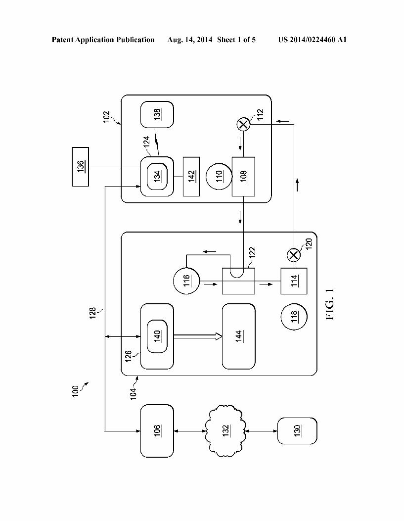
[0016] In some cases, it may be desirable to provide a microchannel heat exchanger in a heating, Ventilation, and/or air-conditioning (HVAC) system. Some microchannel heat exchangers may comprise microchannel tubes and/or fins that may be oriented relative to a primary direction of airflow in a manner that unnecessarily requires more energy to be con sumed to move air through the microchannel heat exchanger. Some systems and methods of this disclosure may provide microchannel heat exchangers and/or air handling units com prising microchannel heat exchangers in which the micro channel tubes and/or fins of the microchannel heat exchang ers are oriented relative to a primary direction of airflow in a manner selected to minimize a pressure drop across the microchannel heat exchanger. This disclosure further con templates microchannel heat exchangers and/or air handling units comprising microchannel heat exchangers in which the microchannel tubes and/or fins of the microchannel heat exchangers are oriented Substantially parallel relative to a primary direction of airflow to minimize a pressure drop across the microchannel heat exchanger. In some embodi ments, the charge tolerant microchannel heat exchanger may be used in an indoor unit and/or an outdoor unit of an HVAC system, including, but not limited to, a heat pump system. [0017] Referring now to FIG. 1, a schematic diagram ofan HVAC system 100 is shown according to an embodiment of the disclosure. HVAC system 100 generally comprises an indoor unit 102, an outdoor unit 104, and a system controller 106. The system controller 106 may generally control opera tion of the indoor unit 102 and/or the outdoor unit 104. As shown, the HVAC system 100 is a so-called heat pump system that may be selectively operated to implement one or more substantially closed thermodynamic refrigeration cycles to provide a cooling functionality and/or a heating functionality. [0018] Indoor unit 102 generally comprises an indoor heat exchanger 108, an indoor fan 110, and an indoor metering device 112. Indoor heat exchanger 108 is a plate fin heat exchanger configured to allow heat exchange between refrig erant carried within internal tubing of the indoor heat exchanger 108 and fluids that contact the indoor heat exchanger 108 but that are kept segregated from the refriger ant. In other embodiments, indoor heat exchanger 108 may comprise a spine fin heat exchanger, a microchannel heat exchanger, or any other suitable type of heat exchanger. (0019] The indoor fan 110 is a centrifugal blower compris ing a blower housing, a blower impeller at least partially disposed within the blower housing, and a blower motor configured to selectively rotate the blower impeller. In other embodiments, the indoor fan 110 may comprise a mixed-flow fan and/or any other suitable type of fan. The indoor fan 110 is configured as a modulating and/or variable speed fan capable of being operated at many speeds over one or more ranges of speeds. In other embodiments, the indoor fan 110

US 2014/0224460 A1
may be configured as a multiple speed fan capable of being operated at a plurality of operating speeds by selectively electrically powering different ones of multiple electromag netic windings of a motor of the indoor fan 110. In yet other embodiments, the indoor fan 110 may be a single speed fan. [0020] The indoor metering device 112 is an electronically controlled motor driven electronic expansion valve (EEV). In alternative embodiments, the indoor metering device 112 may comprise a thermostatic expansion Valve, a capillary tube assembly, and/or any other suitable metering device. The indoor metering device 112 may comprise and/or be associ ated with a refrigerant check Valve and/or refrigerant bypass for use when a direction of refrigerant flow through the indoor metering device 112 is such that the indoor metering device 112 is not intended to meter or otherwise substantially restrict flow of the refrigerant through the indoor metering device 112.
[0021] Outdoor unit 104 generally comprises an outdoor heat exchanger 114, a compressor 116, an outdoor fan 118, an outdoor metering device 120, and a reversing valve 122. Outdoor heat exchanger 114 is a microchannel heat exchanger configured to allow heat exchange between refrig erant carried within internal passages of the outdoor heat exchanger 114 and fluids that contact the outdoor heat exchanger 114 but that are kept segregated from the refriger ant. In other embodiments, outdoor heat exchanger 114 may comprise a plate fin heat exchanger, a spine fin heat exchanger, or any other suitable type of heat exchanger. ['0022] The compressor 116 is a multiple speed scroll type compressor configured to selectively pump refrigerant at a plurality of mass flow rates. In alternative embodiments, the compressor 116 may comprise a modulating compressor capable of operation over one or more speed ranges, a recip rocating type compressor, a single speed compressor, and/or any other suitable refrigerant compressor and/or refrigerant pump. [0023] The outdoor fan 118 is an axial fan comprisinga fan blade assembly and fan motor configured to selectively rotate the fan blade assembly. In other embodiments, the outdoor fan 118 may comprise a mixed-flow fan, a centrifugal blower, and/or any other suitable type of fan and/or blower. The outdoor fan 118 is configured as a modulating and/or Variable speed fan capable of being operated at many speeds over one or more ranges of speeds. In other embodiments, the outdoor fan 118 may be configured as a multiple speed fan capable of being operated at a plurality of operating speeds by selec tively electrically powering different ones of multiple elec tromagnetic windings ofa motor of the outdoor fan 118. In yet other embodiments, the outdoor fan 118 may be a single speed fan. [0024] The outdoor metering device 120 is a thermostatic expansion Valve. In alternative embodiments, the outdoor metering device 120 may comprise an electronically con trolled motor driven EEV similar to indoor metering device 112, a capillary tube assembly, and/or any other suitable metering device. The outdoor metering device 120 may com prise and/or be associated with a refrigerant check Valve and/or refrigerant bypass for use when a direction of refrig erant flow through the outdoor metering device 120 is such that the outdoor metering device 120 is not intended to meter or otherwise substantially restrict flow of the refrigerant through the outdoor metering device 120. [0025] The reversing valve 122 is a so-called four-way reversing valve. The reversing valve 122 may be selectively
Aug. 14, 2014
controlled to alter a flow path of refrigerant in the HVAC system 100 as described in greater detail below. The reversing valve 122 may comprise an electrical solenoid or other device configured to selectively move a component of the reversing valve 122 between operational positions. ['0026] The system controller 106 may generally comprise a touchscreen interface for displaying information and for receiving user inputs. The system controller 106 may display information related to the operation of the HVAC system 100 and may receive user inputs related to operation of the HVAC system 100. However, the system controller 106 may further be operable to display information and receive user inputs tangentially and/or unrelated to operation of the HVAC sys tem 100. In some embodiments, the system controller 106 may not comprise a display and may derive all information from inputs from remote sensors and remote configuration tools. In some embodiments, the system controller 106 may comprise a temperature sensor and may furtherbe configured to control heating and/or cooling of Zones associated with the HVAC system 100. In some embodiments, the system con troller 106 may be configured as a thermostat for controlling supply of conditioned air to Zones associated with the HVAC system 100. ['0027] In some embodiments, the system controller 106 may also selectively communicate with an indoor controller 124 of the indoor unit 102, with an outdoor controller 126 of the outdoor unit 104, and/or with other components of the HVAC system 100. In some embodiments, the system con troller 106 may be configured for selective bidirectional com munication over a communication bus 128. In some embodi ments, portions of the communication bus 128 may comprise a three-wire connection Suitable for communicating mes sages between the system controller 106 and one or more of the HVAC system 100 components configured for interfacing with the communication bus 128. Still further, the system controller 106 may be configured to selectively communicate with HVAC system 100 components and/or any other device 130 via a communication network 132. In some embodi ments, the communication network 132 may comprise a tele phone network, and the other device 130 may comprise a telephone. In some embodiments, the communication net work 132 may comprise the Internet, and the other device 130 may comprise a Smartphone and/or other Internet-enabled mobile telecommunication device. In other embodiments, the communication network 132 may also comprise a remote SerVer.
[0028] The indoor controller 124 may be carried by the indoor unit 102 and may be configured to receive information inputs, transmit information outputs, and otherwise commu nicate with the system controller 106, the outdoor controller 126, and/or any other device 130 via the communication bus 128 and/or any other suitable medium of communication. In some embodiments, the indoor controller 124 may be config ured to communicate with an indoor personality module 134 that may comprise information related to the identification and/or operation of the indoor unit 102. In some embodi ments, the indoor controller 124 may be configured to receive information related to a speed of the indoor fan 110, transmit a control output to an electric heat relay, transmit information regarding an indoor fan 110 Volumetric flow-rate, communi cate with and/or otherwise affect control over an air cleaner 136, and communicate with an indoor EEV controller 138. In some embodiments, the indoor controller 124 may be config ured to communicate with an indoor fan controller 142 and/or

US 2014/0224460 A1
otherwise affect control over operation of the indoor fan 110. In some embodiments, the indoor personality module 134 may comprise information related to the identification and/or operation of the indoor unit 102 and/or a position of the outdoor metering device 120. [0029] In some embodiments, the indoor EEV controller 138 may be configured to receive information regarding tem peratures and/or pressures of the refrigerant in the indoor unit 102. More specifically, the indoor EEV controller 138 may be configured to receive information regarding temperatures and pressures of refrigerant entering, exiting, and/or within the indoor heat exchanger 108. Further, the indoor EEV control ler 138 may be configured to communicate with the indoor metering device 112 and/or otherwise affect control over the indoor metering device 112. The indoor EEV controller 138 may also be configured to communicate with the outdoor metering device 120 and/or otherwise affect control over the outdoor metering device 120. [0030] The outdoor controller 126 may be carried by the outdoor unit 104 and may be configured to receive informa tion inputs, transmit information outputs, and otherwise com municate with the system controller 106, the indoor controller 124, and/or any other device via the communication bus 128 and/or any other Suitable medium of communication. In some embodiments, the outdoor controller 126 may be configured to communicate with an outdoor personality module 140 that may comprise information related to the identification and/or operation of the outdoor unit 104. In some embodiments, the outdoor controller 126 may be configured to receive informa tion related to an ambient temperature associated with the outdoor unit 104, information related to a temperature of the outdoor heat exchanger 114, and/or information related to refrigerant temperatures and/or pressures of refrigerant enter ing, exiting, and/or within the outdoor heat exchanger 114 and/or the compressor 116. In some embodiments, the out door controller 126 may be configured to transmit informa tion related to monitoring, communicating with, and/or oth erwise affecting control over the outdoor fan 118, a compressor sump heater, a solenoid of the reversing Valve 122, a relay associated with adjusting and/or monitoring a refrigerant charge of the HVAC system 100, a position of the indoor metering device 112, and/or a position of the outdoor metering device 120. The outdoor controller 126 may further be configured to communicate with a compressor drive con troller 144 that is configured to electrically power and/or control the compressor 116. [0031] The HVAC system 100 is shown configured for operating in a so-called cooling mode in which heat is absorbed by refrigerant at the indoor heat exchanger 108 and heat is rejected from the refrigerant at the outdoor heat exchanger 114. In some embodiments, the compressor 116 may be operated to compress refrigerant and pump the rela tively high temperature and high pressure compressed refrig erant from the compressor 116 to the outdoor heat exchanger 114 through the reversing valve 122 and to the outdoor heat exchanger 114. As the refrigerant is passed through the out door heat exchanger 114, the outdoor fan 118 may be oper ated to move air into contact with the outdoor heat exchanger 114, thereby transferring heat from the refrigerant to the air surrounding the outdoor heat exchanger 114. The refrigerant may primarily comprise liquid phase refrigerant and the refrigerant may flow from the outdoor heat exchanger 114 to the indoor metering device 112 through and/or around the outdoor metering device 120 which does not substantially
Aug. 14, 2014
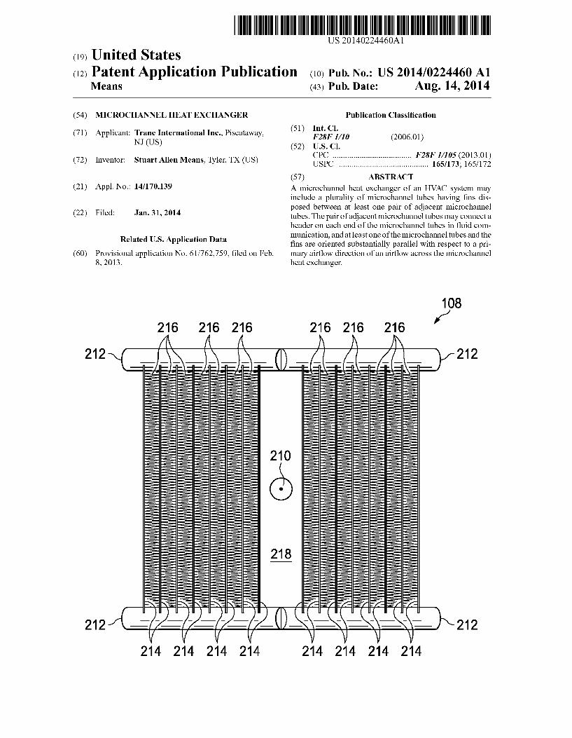
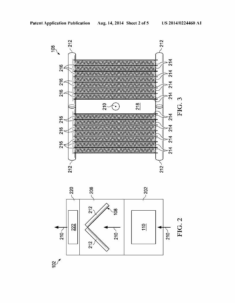
impede flow of the refrigerant in the cooling mode. The indoor metering device 112 may meter passage of the refrig erant through the indoor metering device 112 so that the refrigerant downstream of the indoor metering device 112 is at a lower pressure than the refrigerant upstream of the indoor metering device 112. The pressure differential across the indoor metering device 112 allows the refrigerant down stream of the indoor metering device 112 to expand and/or at least partially convert to a two-phase (vapor and gas) mixture. The two phase refrigerant may enter the indoor heat exchanger 108. As the refrigerantis passed through the indoor heat exchanger 108, the indoor fan 110 may be operated to move air into contact with the indoor heat exchanger 108, thereby transferring heat to the refrigerant from the air sur rounding the indoor heat exchanger 108, and causing evapo ration of the liquid portion of the two phase mixture. The refrigerant may thereafter re-enter the compressor 116 after passing through the reversing Valve 122. [0032] To operate the HVAC system 100 in the so-called heating mode, the reversing valve 122 may be controlled to alter the flow path of the refrigerant, the indoor metering device 112 may be disabled and/or bypassed, and the outdoor metering device 120 may be enabled. In the heating mode, refrigerant may flow from the compressor 116 to the indoor heat exchanger 108 through the reversing valve 122, the refrigerant may be substantially unaffected by the indoor metering device 112, the refrigerant may experience a pres sure differential across the outdoor metering device 120, the refrigerant may pass through the outdoor heat exchanger 114, and the refrigerant may reenter the compressor 116 after passing through the reversing Valve 122. Most generally, operation of the HVAC system 100 in the heating mode reverses the roles of the indoor heat exchanger 108 and the outdoor heat exchanger 114 as compared to their operation in the cooling mode. [0033] Referring now to FIG. 2, a schematic front view of the indoor unit 102 of FIG. 1 comprising a microchannel heat exchanger 108 is shown according to an embodiment of the disclosure. The indoor unit 102 generally comprises a blower cabinet 202 comprising a blower assembly 110 and a heat exchanger cabinet 206 comprising a microchannel heat exchanger 108. In some embodiments, the indoor unit 102 may also comprise a heater cabinet 220 comprising a heater assembly 222. In some embodiments, however, the heater assembly 222 may be disposed within the heat exchanger cabinet 206. The indoor unit 102 may generally comprise a blow-through type air handling unit comprising the micro channel heat exchanger 108 configured in an A-coil arrange ment. However, in alternative embodiments, the indoor unit 102 may be a pull-through type air handling unit in which air is pulled through the microchannel heat exchanger 108 by a blower assembly, suchas blower assembly 110, that is located downstream relative to the microchannel heat exchanger 108. Further, the microchannel heat exchanger 108 may alterna tively be oriented in a V-coil arrangement. In this embodi ment, the blower assembly 204 generally forces air through the indoor unit 102 and the microchannel heat exchanger 108 in a primary airflow direction 210. [0034] Referring now to FIGS. 3-5, top, side, and front views of the microchannel heat exchanger 108 are shown, respectively. The microchannel heat exchanger 108 generally comprises a plurality of tubular headers 212 (not shown in FIG. 5) between which microchannel tubes 214 may extend horizontally to join opposing tubular headers 212 in fluid
US 2014/0224460 A1
communication with each other via a plurality of microchan nels (shown as 224 and in FIG. 6) within each of the micro channel tubes 214. The microchannel tubes 214 may gener ally comprise aflat ribbon shape, and corrugated fins 216 may bejoined between adjacent microchannel tubes 214. In opera tion, air may be forced between adjacent microchannel tubes 214 and into contact with fins 216 to promote heat exchange between the air moved by the blower assembly 110 and the refrigerant flowing through the microchannels of the micro channel tubes 214.
[0035] As viewed from above in FIG. 3, it can be seen that each of the microchannel tubes 214 and associated fins 216 are generally oriented parallel relative to the primary airflow direction 210. More specifically, the flat surfaces of the microchannel tubes 214 may generally be substantially par allel with respect to the primary airflow direction 210. As a result, the pressure drop across the microchannel heat exchanger 108 is minimized. Furthermore, the indoor unit 102 may operate more efficiently at least because less energy is required to move air through the microchannel heat exchanger 108. Still further, as a result of the orientation of the microchannel tubes 214 and/or fins 216 relative to the primary airflow direction 210, condensation formed on the microchannel heat exchanger 108 may be less likely to sepa rate from the microchannel heat exchanger 108 and become entrained in the airflow, thereby exiting the microchannel heat exchanger 108. In some cases, the above-described orienta tion of the microchannel tubes 214 and fins 216 may be described as oriented to provide a minimum footprint area when viewed alonga direction parallel to the primary airflow direction 210 and transverse to a direction of refrigerant flow through the microchannel tubes 214. [0036] As viewed from the side in FIG. 4, it can be seen that a lowest microchannel tube 214 is oriented generally to pro Vide, in this case, a maximum footprint area when Viewed from the side. As viewed from the front in FIG. 5, it can be seen that the above-described orientation of the microchannel tubes 214 and fins 216 may be described as oriented to pro vide a minimum footprint area when Viewed alonga direction transverse to the primary airflow direction 210 and parallel to a direction of refrigerant flow through the microchannel tubes 214. It can also be seen that a significant gap 218 exist between the top located microchannel tubes 214. In some cases, while the gap 218 may reduce a pressure drop across the microchannel heat exchanger 108, because less air may be forced through the microchannel heat exchanger 108an over all efficiency in transferring heat between the microchannel heat exchanger 108 and the air may be reduced relative to a substantially similar microchannel heat exchanger 108 com prising no gap 218. [0037] Referring now to FIG. 6, a partial cutaway oblique view of a microchannel tube 214 of the microchannel heat exchanger 108 is shown according to an embodiment of the disclosure. In some embodiments, each microchannel tube 214 may comprise a plurality of substantially parallel micro channels 224. The microchannels 224 may generally connect the opposing tubular headers 212 in fluid communication. In some embodiments, the microchannel tubes 214 may com prise microchannels 224 that comprise substantially similar diameters. In some embodiments, the microchannel tubes 214 may also comprise a substantially similar number of microchannels 224. In embodiments where the microchannel tubes 214 comprise a substantially similar number of micro channels 224 having substantially similar diameters, it will be
Aug. 14, 2014
appreciated that each microchannel tube 214 may comprise substantially similar microchannel 224 Volumes in each microchannel tube 214.
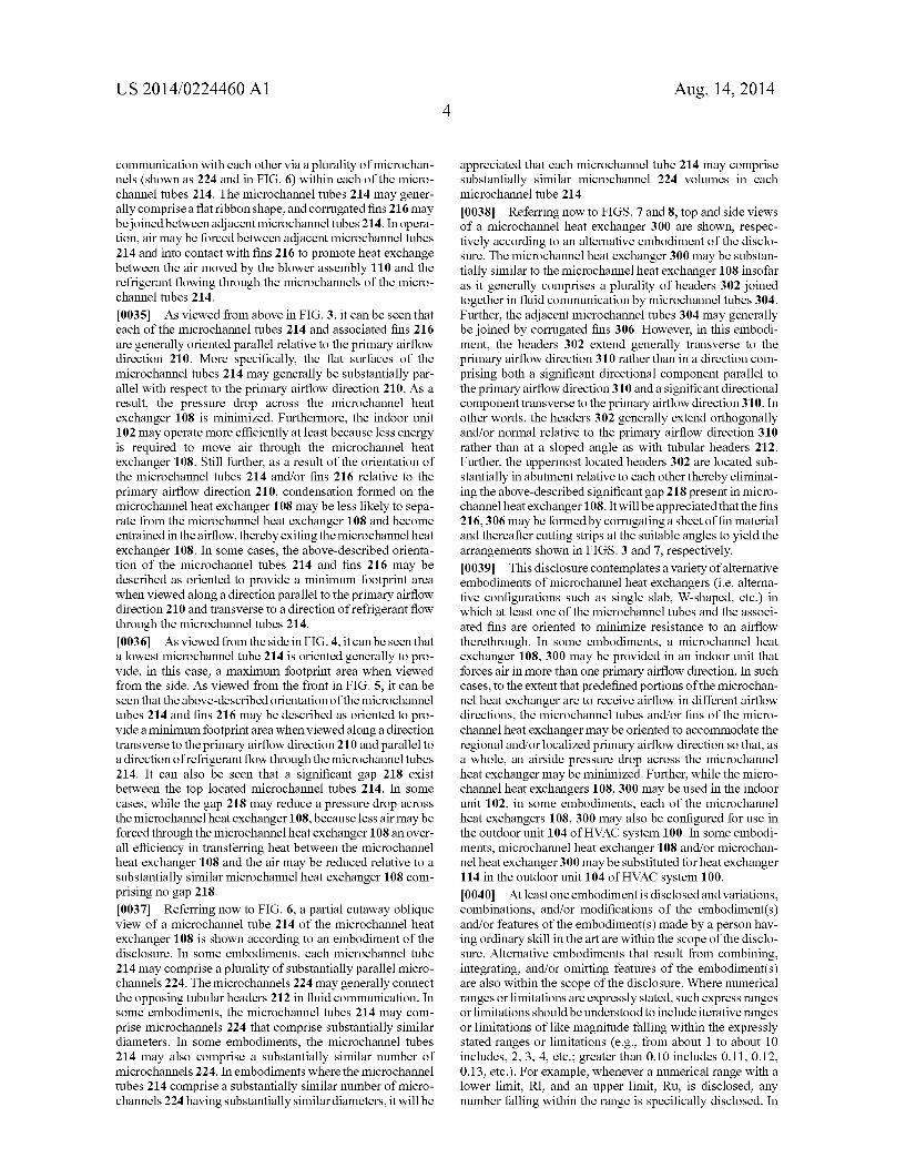
[0038] Referring now to FIGS. 7 and 8, top and side views of a microchannel heat exchanger 300 are shown, respec tively according to an alternative embodiment of the disclo sure. The microchannel heat exchanger 300 may be substan tially similar to the microchannel heat exchanger 108 insofar as it generally comprises a plurality of headers 302 joined together in fluid communication by microchannel tubes 304. Further, the adjacent microchannel tubes 304 may generally be joined by corrugated fins 306. However, in this embodi ment, the headers 302 extend generally transverse to the primary airflow direction 310 rather than in a direction com prising both a significant directional component parallel to the primary airflow direction 310 and a significant directional component transverse to the primary airflow direction 310. In other words, the headers 302 generally extend orthogonally and/or normal relative to the primary airflow direction 310 rather than at a sloped angle as with tubular headers 212. Further, the uppermost located headers 302 are located sub stantially in abutment relative to each other thereby eliminat ing the above-described significant gap 218 present in micro channel heat exchanger 108. It will be appreciated that the fins 216, 306 may be formed by corrugatinga sheet offin material and thereafter cutting strips at the suitable angles to yield the arrangements shown in FIGS. 3 and 7, respectively. [0039] This disclosure contemplates a variety ofalternative embodiments of microchannel heat exchangers (i.e. alterna tive configurations such as single slab, W-shaped, etc.) in which at least one of the microchannel tubes and the associ ated fins are oriented to minimize resistance to an airflow therethrough. In some embodiments, a microchannel heat exchanger 108, 300 may be provided in an indoor unit that forces air in more than one primary airflow direction. In Such cases, to the extent that predefined portions of the microchan nel heat exchanger are to receive airflow in different airflow directions, the microchannel tubes and/or fins of the micro channel heat exchanger may be oriented to accommodate the regional and/or localized primary airflow direction so that, as a whole, an airside pressure drop across the microchannel heat exchanger may be minimized. Further, while the micro channel heat exchangers 108, 300 may be used in the indoor unit 102, in some embodiments, each of the microchannel heat exchangers 108, 300 may also be configured for use in the outdoor unit 104 of HVAC system 100. In some embodi ments, microchannel heat exchanger 108 and/or microchan nel heat exchanger 300 may be substituted for heat exchanger 114 in the outdoor unit 104 of HVAC system 100. [0040] At least one embodimentis disclosed and variations, combinations, and/or modifications of the embodiment(s) and/or features of the embodiment(s) made by a person hav ing ordinary skill in the art are within the scope of the disclo sure. Alternative embodiments that result from combining, integrating, and/or omitting features of the embodiment(s) are also within the scope of the disclosure. Where numerical ranges or limitations are expressly stated, such express ranges or limitations should be understood to include iterative ranges or limitations of like magnitude falling within the expressly stated ranges or limitations (e.g., from about 1 to about 10 includes, 2, 3, 4, etc.; greater than 0.10 includes 0.11, 0.12, 0.13, etc.). For example, whenever a numerical range with a lower limit, Rl, and an upper limit, Ru, is disclosed, any number falling within the range is specifically disclosed. In
