15. compressible flowfmectt.lecturer.eng.chula.ac.th/2103342/chapter15.pdf · for ideal gases) due...
TRANSCRIPT

15. Compressible Flow
In thermodynamics, the “simple compressible” substance is referred to as a substance, in which the change of the specific volume is important. So far, the change of the specific volume is caused by a process associated with heat and work mixing accelerating or decelerating flow at
low speed However, the change of the specific volume due to the flow itself has not yet mentioned. In fluid mechanics, we always use the term “incompressible flow” to represent a low-speed flow. If the flow is accelerated to a certain limit, the change of the specific volume becomes significant.

15.1 Stagnation Properties
The isentropic stagnation state is the state of a flowing fluid if it undergoes a reversible adiabatic decelerating to zero velocity.
2
hh2
o
V
The subscript “o” denotes for the stagnation state. The stagnation properties are properties at the stagnation state: Stagnation pressure (Po) [Pa] Stagnation temperature (To) [K] Stagnation density (o) [kg/m3]

Note: The difference between the actual
and isentropic stagnation states is due to irreversibilities.
For most nozzles and diffusers, which are adiabatic, ho2=ho1 (and To2=To1 for ideal gases) due to the first law.
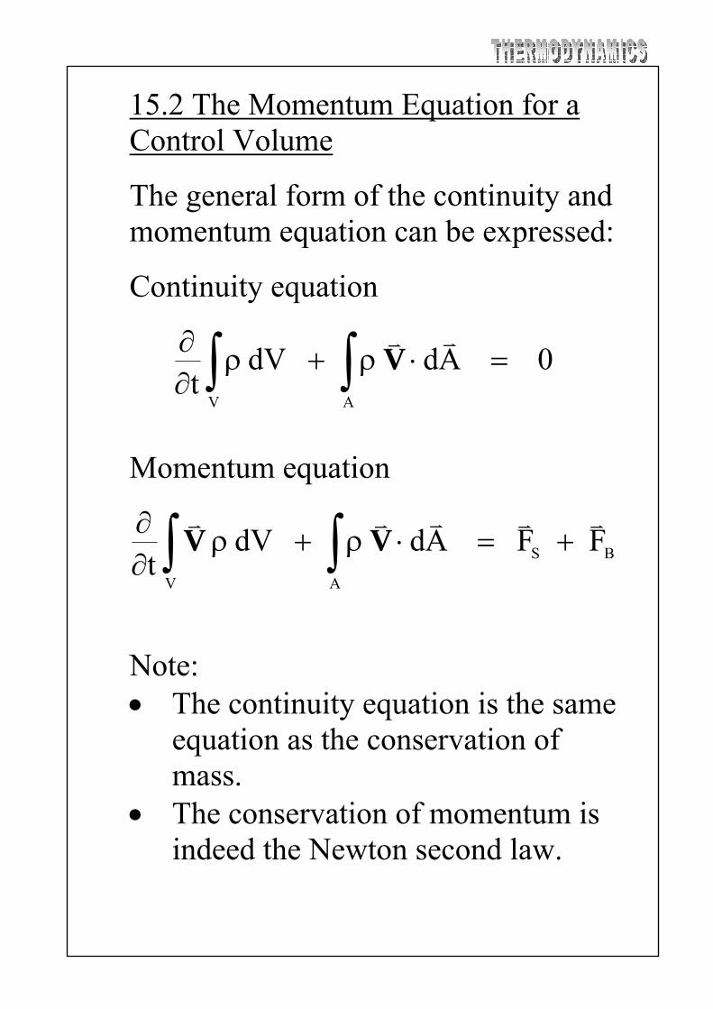
15.2 The Momentum Equation for a Control Volume
The general form of the continuity and momentum equation can be expressed:
Continuity equation
0 Ad dV t
AV
V
Momentum equation
BS
AV
F F Ad dV t
V V
Note: The continuity equation is the same
equation as the conservation of mass.
The conservation of momentum is indeed the Newton second law.

15.3 Forces Acting on a Control Surface
The summations of all forces in both x and y directions are
xxeoexioix RAPPAPPF
yyeoeyioiy RAPPAPPF
All of these forces will present the surface force in the RHS of the momentum equation.

15.4 Adiabatic, one-dimensional, steady-state flow of an incompressible fluid through a nozzle
Continuity equation:
eeiiie AAmm VV
The first law:
0g)ZZ(2
hh ie
2
i
2
eie
VV
From TdS = dh v dP = 0
)PP(vhh ieie
Thus, we have
0g)ZZ(2
)PP(v ie
2
i
2
eie
VV
This is the well-known Bernoulli equation derived from a combine first and second law.
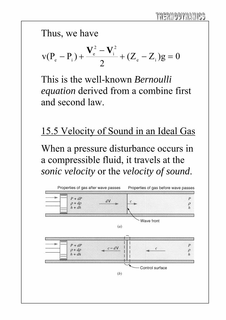
15.5 Velocity of Sound in an Ideal Gas
When a pressure disturbance occurs in a compressible fluid, it travels at the sonic velocity or the velocity of sound.

The first law:
2
)d(c)dhh(
2
ch
22 V
0dcdh V
Continuity:
)dc(A)d(Ac V 0dcd V
Also, the relation among properties:
0dP
dhTdS
(isentropic flow)
Eliminating dh using the first law gives
0cddP
V
The above equation can be derived using the momentum equation:

)cdc(A
)cdc(mA)dPP(PA
VV
V
0cddP V
Eliminating dV using the continuity equation yields
2c d
dP
Since the isentropic process is assumed, the partial derivative should be used:
2
s
c P
Thus, c is a property as well as other properties. If the equation of state is known, the above expression can be solved. For an ideal gas,
const P/ Pv kk

Differentiate
Pk c
P
Pk
d
dP
dk
P
dP
2
s
Using the ideal-gas law: P = RT
or kRT c 2 kRT c The Mach number (M) [-]: the ratio of the actual velocity to the sonic velocity.
c
M V
When M < 1 the flow is subsonic M 1 the flow is transonic M > 1 the flow is supersonic
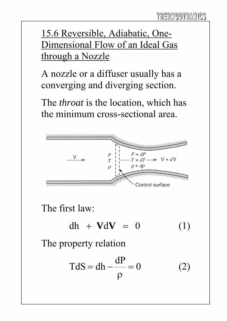
15.6 Reversible, Adiabatic, One-Dimensional Flow of an Ideal Gas through a Nozzle
A nozzle or a diffuser usually has a converging and diverging section.
The throat is the location, which has the minimum cross-sectional area.
The first law:
0 d dh VV (1)
The property relation
0dP
dhTdS
(2)

Continuity:
onstantc m A V
0 d
A
dAd
V
V (3)
Combining (1) and (2) gives
VVd dP
dh
0 d dP VV (4)
The above equation can be obtained by using the momentum equation.
Substituting (4) into (3) gives
2
1
)d/dP(
1dP
dd
A
dA
V
V
V
Since the flow is isentropic:
2
22
M c
d
dP
V

Thus
2
2M1
dP
A
dA
V (5)
There are some significant results from these equations For a nozzle, dV > 0 (accelerating flow) From (1), dh < 0 or dT < 0 From (2), dP < 0 From (5), If M < 1, dA < 0 If M > 1, dA > 0 For a nozzle, dV < 0 (decelerating flow) From (1), dh > 0 or dT > 0 From (2), dP > 0 From (5), If M < 1, dA > 0 If M > 1, dA < 0 Note: M = 1, dA = 0: the sonic velocity can be achieve only at the throat

Recall the first law: 2
hh2
o
V
1
T
T
1k
kRT2)TT(C2 o
oPo
2V
Since c2 = kRT
1
T
T
1k
c2 o
22V
2o M2
1k1
T
T
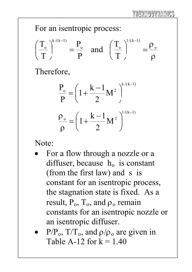
For an isentropic process:
P
P
T
T o
)1k/(k
o
and
o
)1k/(1
o T
T
Therefore,
)1k/(k
2o M2
1k1
P
P
)1k/(1
2o M2
1k1
Note: For a flow through a nozzle or a
diffuser, because ho is constant (from the first law) and s is constant for an isentropic process, the stagnation state is fixed. As a result, Po, To, and o remain constants for an isentropic nozzle or an isentropic diffuser.
P/Po, T/To, and /o are given in Table A-12 for k = 1.40

The conditions are M = 1 is called the critical properties denoting by the superscript *. Thus, we have
1k/1
o
*
)1k/(k
o
*
o
*
1k
2
1k
2
P
P
1k
2
T
T
15.7 Mass Rate of Flow of an Ideal Gas through an Isentropic Nozzle
The mass rate of flow per unit area can be determined:
2
o
M2
1k1
R
k
T
PM
A
m V
Rewrite this equation in terms of stagnation properties:

)1k(2/)1k(
2o
o
M2
1k1
M
R
k
T
P
A
m
By setting M = 1, we have
)1k(2/)1k(
o
o
*
2
1k
1
R
k
T
P
A
m
Dividing both two equations gives
)1k(2/)1k(
2
*M
2
1k1
1k
2
M
1
A
A
The value of A/A* are also given in Table A.12.
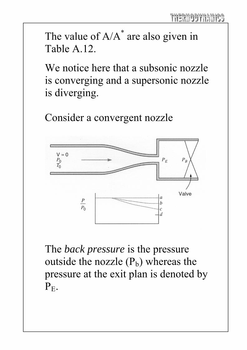
We notice here that a subsonic nozzle is converging and a supersonic nozzle is diverging. Consider a convergent nozzle
The back pressure is the pressure outside the nozzle (Pb) whereas the pressure at the exit plan is denoted by PE.

Consider the variation of and Pm E /Po with PB/Po.
At a, PE = PB = Po and no flow. At b, PE = PB and there is subsonic
flow everywhere in the nozzle. At c, ME = 1, PE = PB = critical
pressure At d, ME = 1, PE = critical pressure,
but m and P E remain constants beyond point c, and PE ≠ PB. The nozzle is choked.

Consider a convergent-divergent nozzle
At a, PE = PB = Po and no flow. Between a and c, flow is subsonic
throughout the nozzle. At c, M* = 1 at the throat, and the
subsonic flow occurs in the divergent section.
Between c and d, the flow is discontinuous and is not entirely isentropic.
At d (the design condition), the flow is entirely isentropic and is supersonic in the divergent section.
Beyond d, PE ≠ PB and PE remains constant.

15.9 Nozzle and Diffuser Coefficients The nozzle coefficient (N) [-]:
EP same andconst sexit with nozzleat KE
exit nozzle at the KE ActualN
si0
ei0N hh
hh
Note: Generally, (N) varies from 90 to 99 percent.

The velocity coefficient (CV) [-]:
EP same andconst sexit with nozzleat
exit nozzle at the ActualVC
V
V
NVC
The coefficient of discharge (CD) [-]:
constsexit with nozzleat m
m ActualDC
Note: if the nozzle is not choked, the actual PB is used to calculate at the isentropic condition. If the nozzle is choked, m is based on the isentropic flow at the design condition.
m
For a diffuser, because the exit state of the diffuser is not necessary to be a stagnation state, the isentropic state (state 3) must be determined

The diffuser coefficient (D) [-]:
102
13
101
13
2
1
sD hh
hh
hh
hh
2/
h
V
Note: h01 = h02 due to the first law.
By assuming an ideal gas with constant specific heat, we have
2
1
k/)1k(
1o
2o2
1
D
M2
1k
1P
PM
2
1k1

15.10 Nozzles and Orifices as Flow-Measuring Devices
The rate of in a pipe is usually determined by measuring P across a nozzle or an orifice.
m
For incompressible fluids, by using the Bernoulli and continuity equations
02
)Pv(P2
1
2
212
VV
0
2
A/A)Pv(P
2
212
2
212
VV
2
12
122
A/A1
)Pv(P2
V
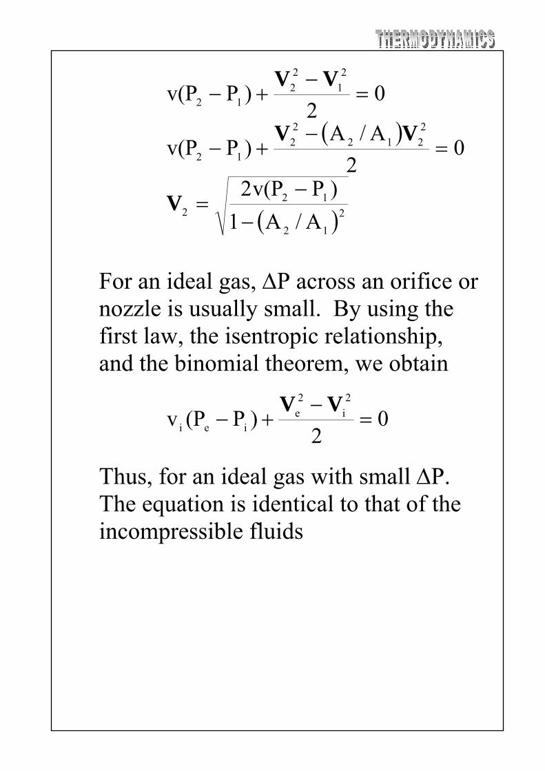
For an ideal gas, P across an orifice or nozzle is usually small. By using the first law, the isentropic relationship, and the binomial theorem, we obtain
02
)P(Pv2
i
2
eiei
VV
Thus, for an ideal gas with small P. The equation is identical to that of the incompressible fluids
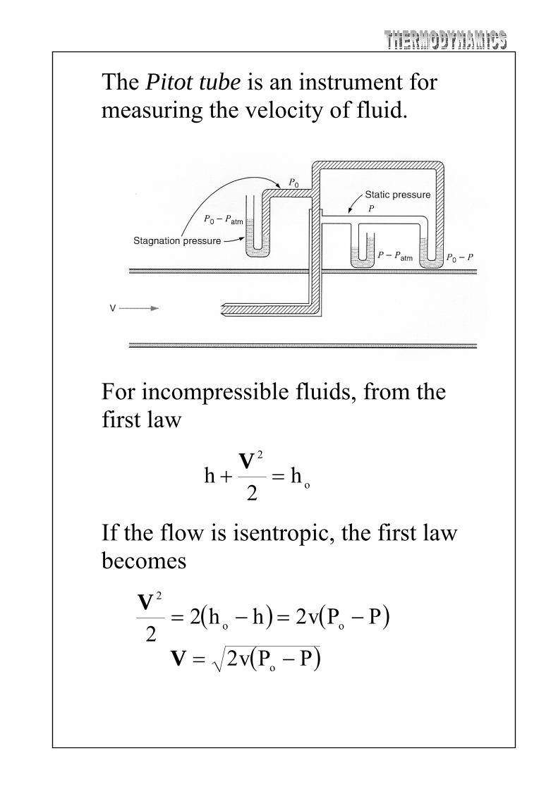
The Pitot tube is an instrument for measuring the velocity of fluid.
For incompressible fluids, from the first law
o
2
h2
h V
If the flow is isentropic, the first law becomes
PPv2hh22 oo
2
V
PPv2 o V

For compressible fluids with an ideal-gas assumption, by using the ideal gas law, the isentropic relation for an compressible flow, and the binomial theorem, we obtain
2
o
2
o
o
c4
11
2/
PP
V
V
By comparing the result with the incompressible flow:
12/
PP2
o
o
V
Thus, the term 2
oc25.0 V/ represents the error involving incompressible assumption.