15 hp 2004 4 stroke
TRANSCRIPT


SUPPLEMENTARY SERVICE MANUAL
66M-28197-ZA-1X
F15Z
LIT-18616-02-12

NOTICEThis Supplementary Service Manual has been prepared to introduce new service and data for the F15Z. For complete service information procedures, it is necessary to use this Supplementary Service Manual together with the following manual.
F15Z
SUPPLEMENTARY SERVICE MANUAL
©2000 by Yamaha Motor Corporation, U.S.A.
1st Edition, April 2000
All rights reserved. Any reprinting or
unauthorized use without the written
permission of Yamaha Motor Corporation, U.S.A.
is expressly prohibited.
Printed in USA
P/N LIT-18616-02-12
F15A (F15) SERVICE MANUAL: 66M-28197-Z7-11

HOW TO USE THIS MANUAL
MANUAL FORMAT
All of the procedures in this manual are organised in a sequential, step-by-step format. Theinformation has been compiled to provide the mechanic with an easy to read, handyreference that contains comprehensive explanations of all disassembly, repair, assembly, andinspection operations.In this revised format, the condition of a faulty component will precede an arrow symbol andthe course of action required will follow the symbol, e.g.,
•BearingsPitting/scratches Replace.
MODEL INDICATION
Multiple models are referred to in this manual and their model indications are noted asfollows.
ILLUSTRATIONS
The illustrations within this service manual represent all of the designated models.
CROSS REFERENCES
The cross references have been kept to a minimum. Cross references will direct you to theappropriate section or chapter.
Model name F15AEP F15AEHP
USA and Canada name F15PR F15PH
Indication F15AEP F15AEHP
IMPORTANT INFORMATION
In this Service Manual particularly important information is distinguished in the followingways.
The safety Alert Symbol means ATTENTION! BECOME ALERT! YOUR SAFETY ISINVOLVED!
WARNING
Failure to follow WARNING instructions could result in severe injury or death to the machine
operator, a bystander or a person inspecting or repairing the outboard motor.
CAUTION
A CAUTION indicates special precautions that must be taken to avoid damage to the
outboard motor.
NOTE:A NOTE provides key information to make procedures easier or clearer.
HOW TO USE THIS MANUAL
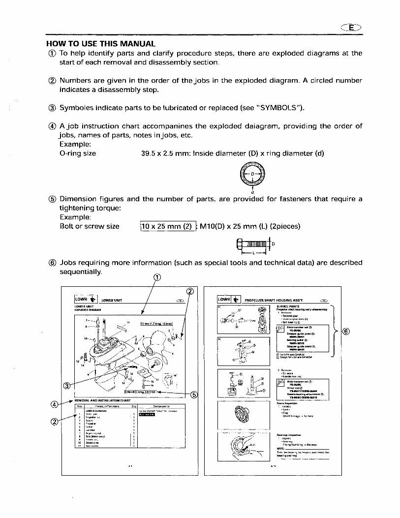
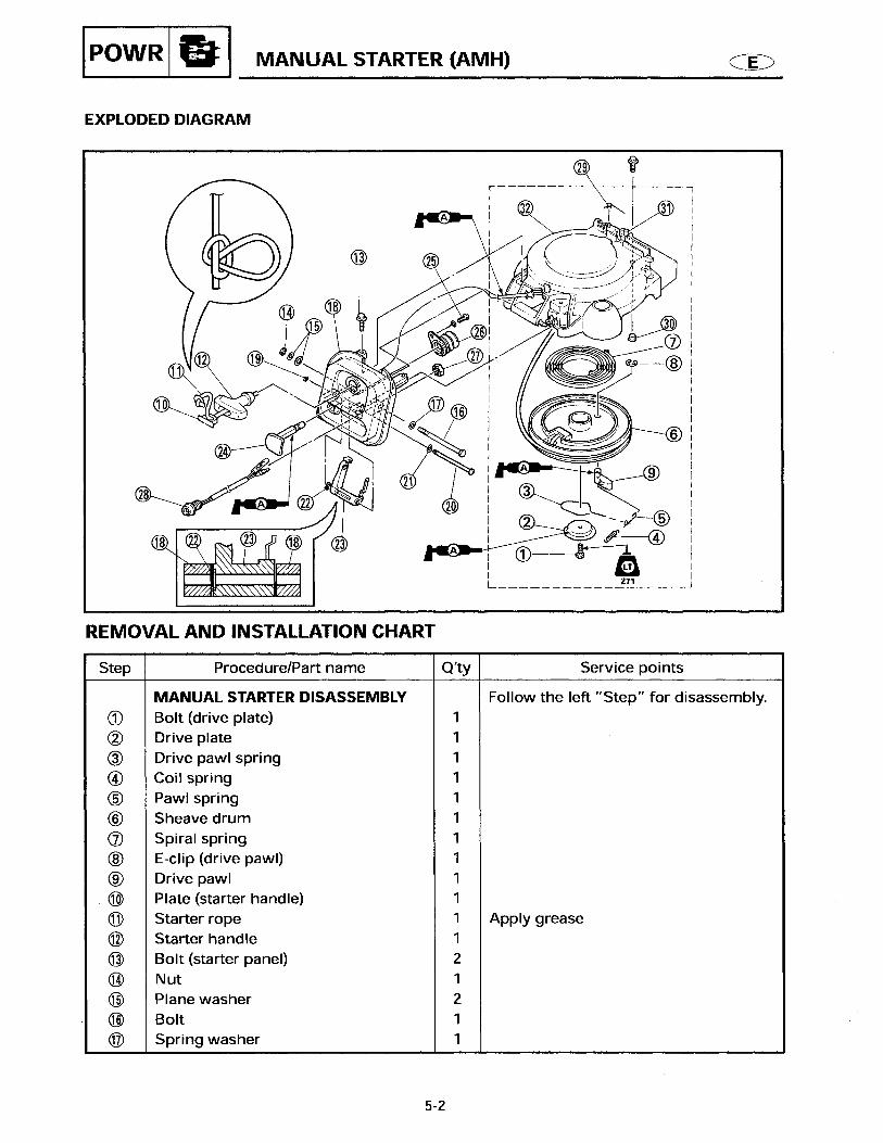
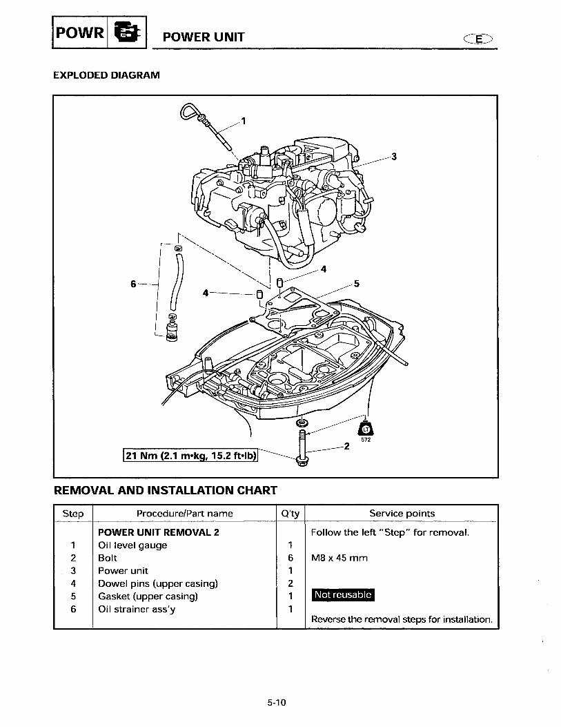
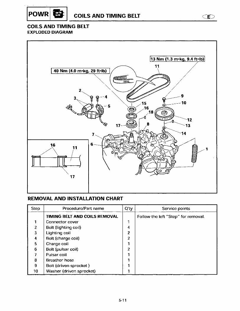
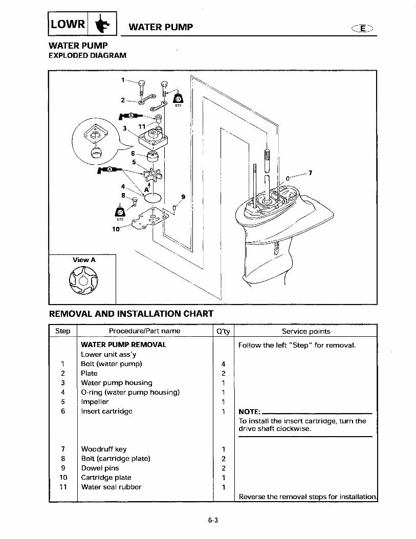
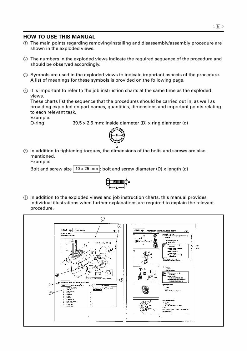
1 The main points regarding removing/installing and disassembly/assembly procedure are shown in the exploded views.
2 The numbers in the exploded views indicate the required sequence of the procedure and should be observed accordingly.
3 Symbols are used in the exploded views to indicate important aspects of the procedure.A list of meanings for these symbols is provided on the following page.
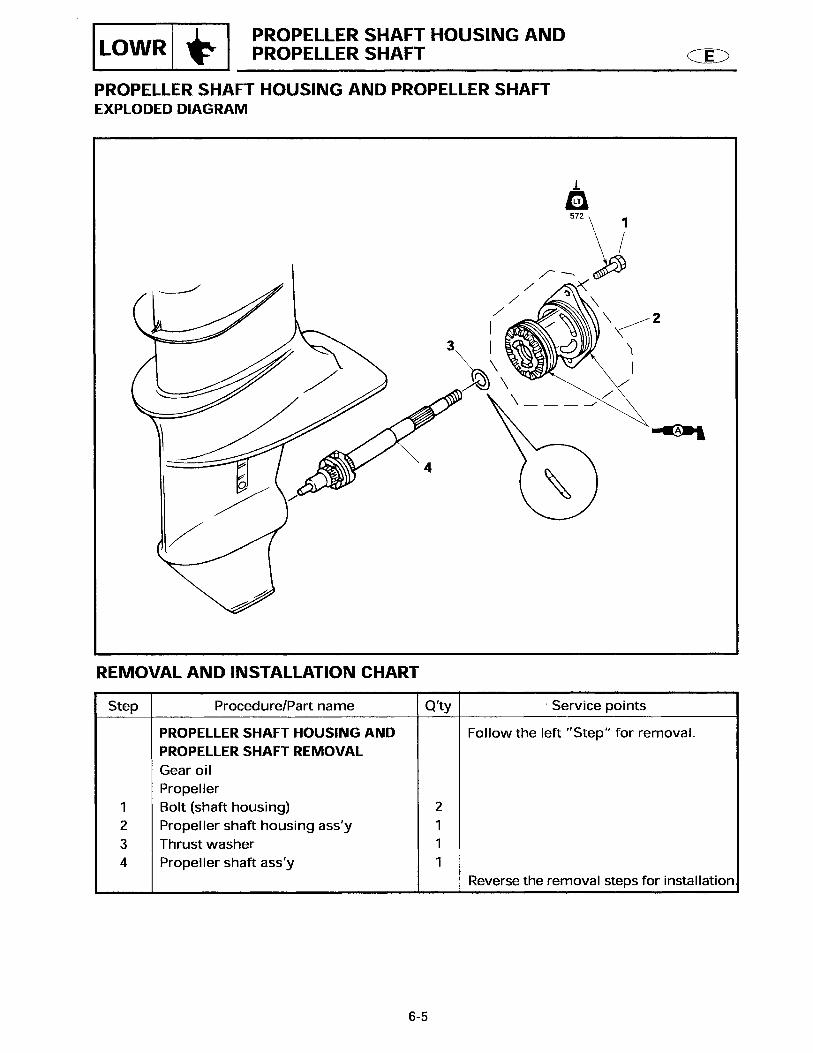
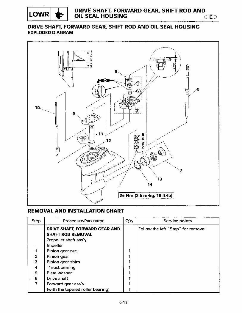
4 It is important to refer to the job instruction charts at the same time as the exploded views.These charts list the sequence that the procedures should be carried out in, as well as providing exploded on part names, quantities, dimensions and important points relating to each relevant task.Example:O-ring 39.5 x 2.5 mm: inside diameter (D) x ring diameter (d)
5 In addition to tightening torques, the dimensions of the bolts and screws are also mentioned.Example:
Bolt and screw size : bolt and screw diameter (D) x length (d)
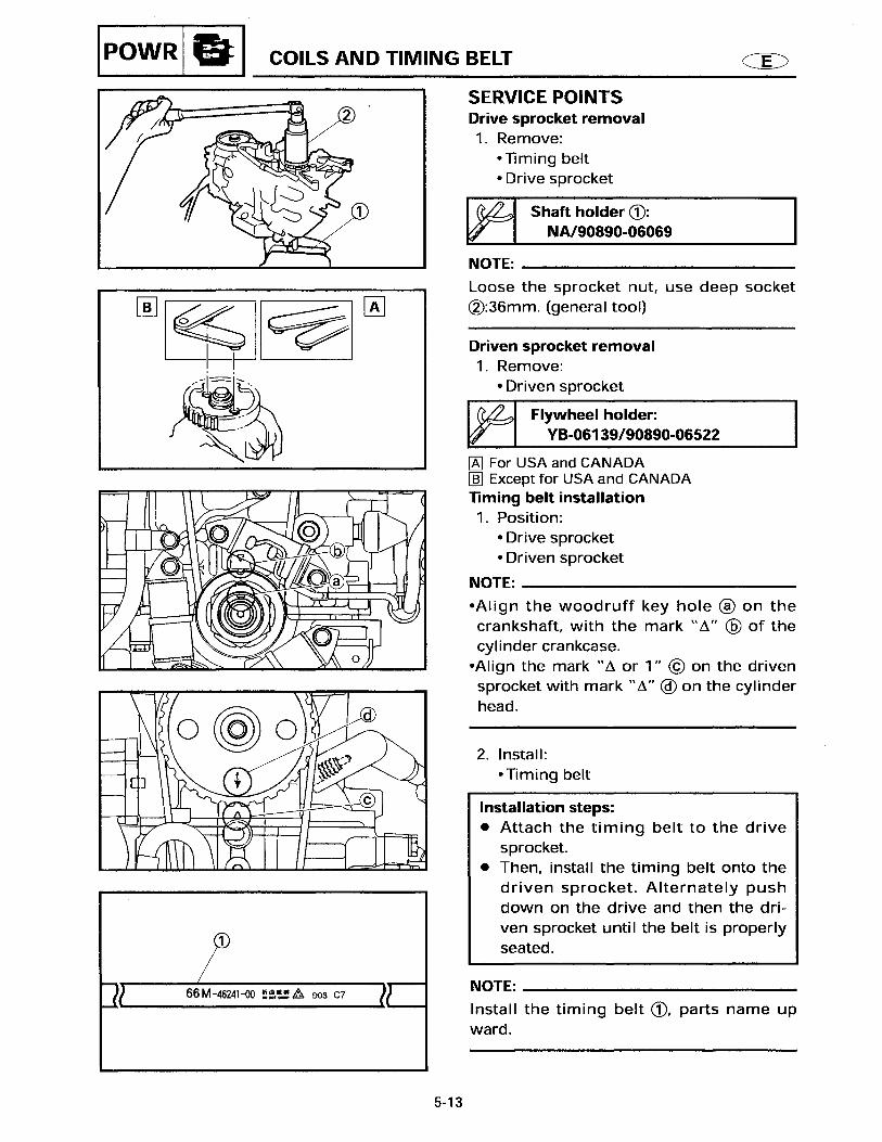
6 In addition to the exploded views and job instruction charts, this manual provides individual illustrations when further explanations are required to explain the relevant procedure.
10 x 25 mm

SYMBOLS
Symbols 1 to 9 are designed as thumb-tabsto indicate the content of a chapter.
1 General information2 Specifications3 Periodic check and adjustment4 Fuel system5 Power unit6 Lower unit7 Bracket unit8 Electrical system9 Trouble analysis
Symbols : to E indicate specific data.: Special toolA Specified liquidB Specified engine speedC Specified torqueD Specified measurementE Specified electrical value
[Resistance (Ω), Voltage (V), Electrical current (A)]
Symbols F to H in an exploded diagramindicate the grade of lubricant and thelocation of the lubricant point.
F Apply Yamaha 4-stroke motor oilG Apply water resistant grease
(Yamaha grease A, Yamaha marine grease)
H Apply molybdenum disufied oil
Symbols I to N in an exploded diagramindicate the grade of the sealing or lockingagent and the location of the applicationpoint.I Apply Gasket Maker® J Apply Yamabond #4
(Yamaha bond number 4)K Apply LOCTITE® No.271 (Red LOCTITE)L Apply LOCTITE® No.242 (Blue LOCTITE)M Apply LOCTITE® No.572N Apply silicon sealant
1 2
3 4
5 6
7 8
9 :
A B
C D
E F
G H
I J
K L
M N

GENERAL INFORMATION
IDENTIFICATION................................................................................................. 1
SERIAL NUMBER ......................................................................................... 1STARTING SERIAL NUMBERS ................................................................... 1
SPECIAL TOOLS ................................................................................................. 2
REMOVAL AND INSTALLATION ................................................................ 2
SPECIFICATIONS
GENERAL SPECIFICATIONS.............................................................................. 3
MAINTENANCE SPECIFICATIONS.................................................................... 5
POWER UNIT................................................................................................ 5LOWER.......................................................................................................... 8ELECTRICAL ................................................................................................. 8DIMENSIONS ............................................................................................. 11
TIGHTENING TORQUES .................................................................................. 13
SPECIFIED TORQUES ................................................................................ 13GENERAL TORQUES ................................................................................. 14
PERIODIC INSPECTIONS AND ADJUSTMENT
MAINTENANCE INTERVAL CHART ................................................................ 15
POWER TILT SYSTEM...................................................................................... 16
CHECKING THE POWER TILT (PT) FLUID LEVEL .................................... 16
GENERAL .......................................................................................................... 16
CHECKING THE ANODE ............................................................................ 16
POWER UNIT
POWER UNIT .................................................................................................... 17
REMOVING/INSTALLING THE POWER UNIT 1 (F15AEP/F15PR) ........... 17REMOVING/INSTALLING THE POWER UNIT 1 (F15AEHP/F15PH) ........ 19
ELECTRICAL UNIT............................................................................................ 21
REMOVING/INSTALLING THE ELECTRICAL UNIT .................................. 21
CYLINDER HEAD AND OIL PUMP................................................................... 24
REMOVING/INSTALLING THE CYLINDER HEAD AND OIL PUMP ......... 24
OIL PUMP.......................................................................................................... 25
DISASSEMBLING/ASSEMBLING THE OIL PUMP ................................... 25
CAMSHAFT AND VALVE................................................................................. 26
REMOVING/INSTALLING THE CAMSHAFT AND VALVE ....................... 26CHECKING THE ROCKER ARM AND ROCKER ARM SHAFT .................. 28CHECKING THE CAMSHAFT..................................................................... 28REFACING THE VALVE SEAT ................................................................... 29INSTALLING THE CAMSHAFT OIL SEAL................................................. 30

OIL FILTER, THERMOSTAT AND EXHAUST COVER..................................... 31
DISASSEMBLING/ASSEMBLING THE OIL FILTER, THERMOSTAT AND EXHAUST COVER ............................................................................. 31
BRACKET UNIT
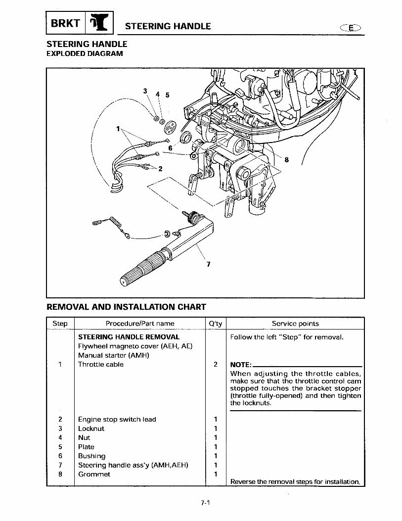
STEERING HANDLE ASSEMBLY (F15AEHP/F15PH) ..................................... 33
REMOVING/INSTALLING THE STEERING HANDLE ASSEMBLY........... 33DISASSEMBLING/ASSEMBLING THE STEERING HANDLE ASSEMBLY................................................................................................. 34INSTALLING THE PT SWITCH .................................................................. 36
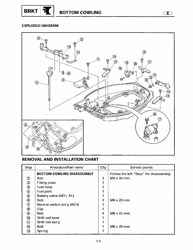
BOTTOM COWLING ASSEMBLY .................................................................... 37
REMOVING/INSTALLING THE BOTTOM COWLING ASSEMBLY .......... 37
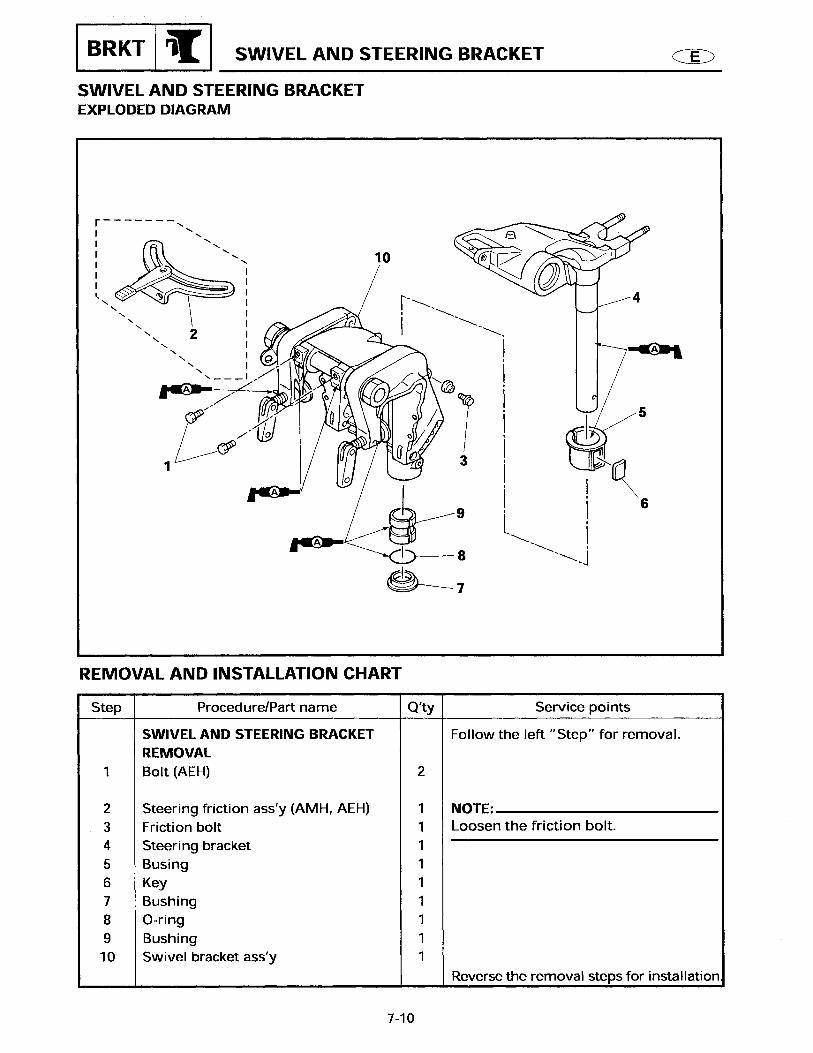
SWIVEL AND STEERING BRACKET................................................................ 40
REMOVING/INSTALLING THE SWIVEL AND STEERING BRACKET ...... 40
POWER TILT (PT) UNIT .................................................................................... 41
REMOVING/INSTALLING THE POWER TILT (PT) UNIT .......................... 41DISASSEMBLING/ASSEMBLING THE POWER TILT (PT) CYLINDER .... 43DISASSEMBLING THE POWER TILT (PT) CYLINDER ............................. 45ASSEMBLING THE POWER TILT (PT) CYLINDER ................................... 46DISASSEMBLING/ASSEMBLING THE VALVES AND PUMP 1 ............... 50INSTALLING THE RELIEF VALVE.............................................................. 52DISASSEMBLING/ASSEMBLING THE PT MOTOR.................................. 53REMOVING THE ARMATURE ................................................................... 54CHECKING THE PT MOTOR ...................................................................... 54CHECKING THE PT MOTOR ASSEMBLY ................................................. 56INSTALLING THE OIL SEAL ...................................................................... 56DISASSEMBLING/ASSEMBLING THE VALVES AND PUMP 2 ............... 57
CLAMP BRACKET............................................................................................. 59
REMOVING/INSTALLING THE CLAMP BRACKET ................................... 59
ELECTRICAL SYSTEM
ELECTRICAL COMPONENTS........................................................................... 61
TOP VIEW AND PORT SIDE VIEW ............................................................ 61FRONT VIEW (F15AEP/F15PH) .................................................................. 62FRONT VIEW (F15AEHP/F15PH) ............................................................... 63
STARTER MOTOR ............................................................................................ 64
DISASSEMBLING/ASSEMBLING THE STARTER MOTOR...................... 64REMOVING THE PINION NUT .................................................................. 66CHECKING THE PINION GEAR ................................................................. 66CHECKING THE ARMATURE .................................................................... 66CHECKING THE BRUSH HOLDER............................................................. 67

POWER TILT (PT) SYSTEM.............................................................................. 68
POWER TILT (PT) SYSTEM (F15AEP/F15PR) ........................................... 68POWER TILT (PT) SYSTEM (F15AEHP/F15PH) ........................................ 69CHECKING THE PT SWITCH ..................................................................... 70CHECKING THE TRAILER SWITCH ........................................................... 70CHECKING THE PT RELAY ........................................................................ 70
TROUBLE ANALYSIS
TROUBLE ANALYSIS ....................................................................................... 72
TROUBLE ANALYSIS CHART ................................................................... 72

IDENTIFICATION
1
IDENTIFICATION
SERIAL NUMBER
The outboard motor’s serial number is stamped on a label which is attached to the port clamp bracket.
NOTE:As an antitheft measure, a special label on which the outboard motor’s serial number is stamped is bonded to the port clamp bracket. The label is specially treated so that peeling it off causes cracks across the serial number.
1 Model name2 Approval model code3 Transom height4 Serial number
STARTING SERIAL NUMBERS
The starting serial number blocks are as follows:
Model name Applicable model code
Starting serial
numberWorld wide
USA/Canada
F15AEP F15PR 66M L:800141-F15AEHP F15PH 66M L:900111-

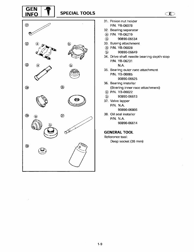
SPECIAL TOOLS
2
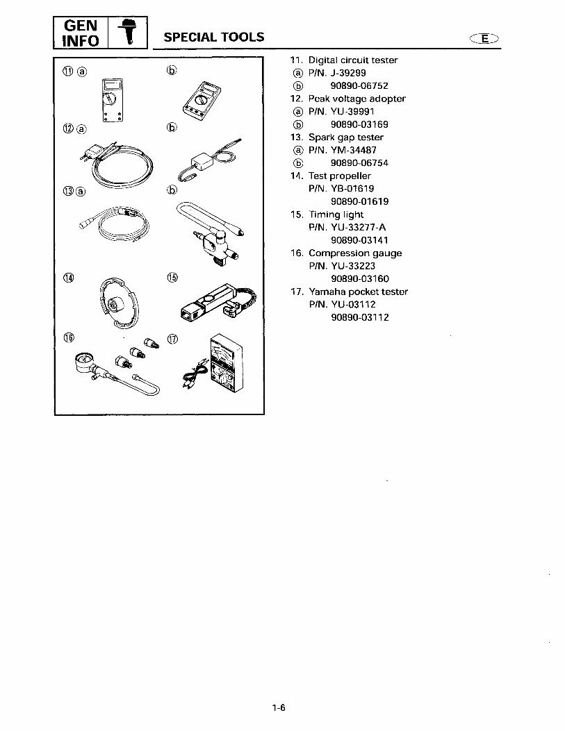
SPECIAL TOOLSUsing the correct special tools recommended by Yamaha, will aid the work and enable accurate assembly and tune-up.Improvising and using improper tools can damage the equipment.
NOTE: For U.S.A. and Canada, use part numbers
that start with “J-”, “YB-” “YM-”, “YU-” or “YW-”.
For other countries, use part numbers that start with “90890-”.
REMOVAL AND INSTALLATION
1 Power tilt wrench:
2 Oil seal attachment:
3 Driver rod:
4 Valve seat cutter set:
5 Valve seat cutter:
P/N. YB-0656090890-06560
P/N. YB-06112, YB-06196 ..............a90890-06614, 90890-06196....b
P/N. YB-06071 ................................a90890-06652...........................b
P/N. 90890-06803
P/N. 90890-06556
a2 b
a3 b
4 5
1

GENERAL SPECIFICATIONS
3
GENERAL SPECIFICATIONS
Item Unit
ModelWorld wide F15AEP F15AEHP
USA F15PR F15PHCanada F15PR F15PH
DIMENSION
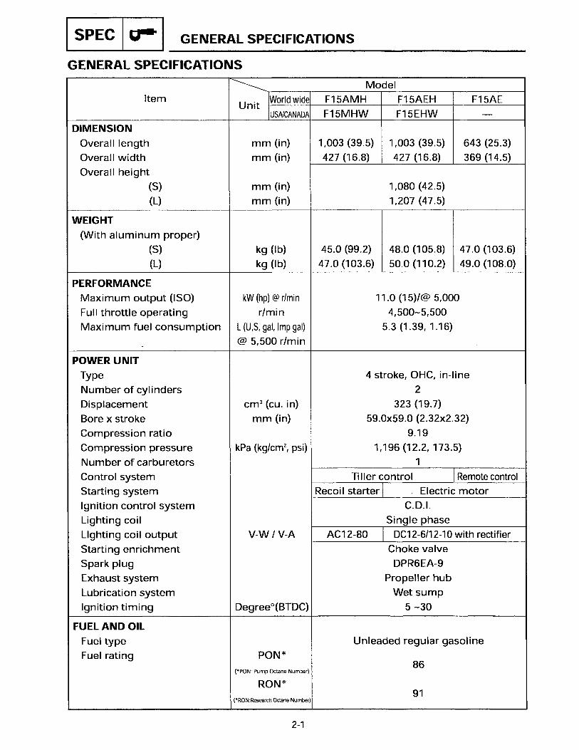
Overall length mm (in) 643 (25.3) 1,001 (39.4)Overall width mm (in) 369 (14.5) 427 (16.8)Overall height mm (in) 1,207 (47.5) 1,207 (47.5)
WEIGHT
(with aluminum propeller) kg (lb) 54 (119.0) 55 (121.3)PERFORMANCE
Maximum output kW (hp) @ 5,000 r/min
11 (15)
Full throttle operating range r/min 4,500 - 5,500Maximum fuel consumption L (US gal, lmp
gal)/h @ 5,000 r/min
5.3 (1.39, 1.16)
POWER UNIT
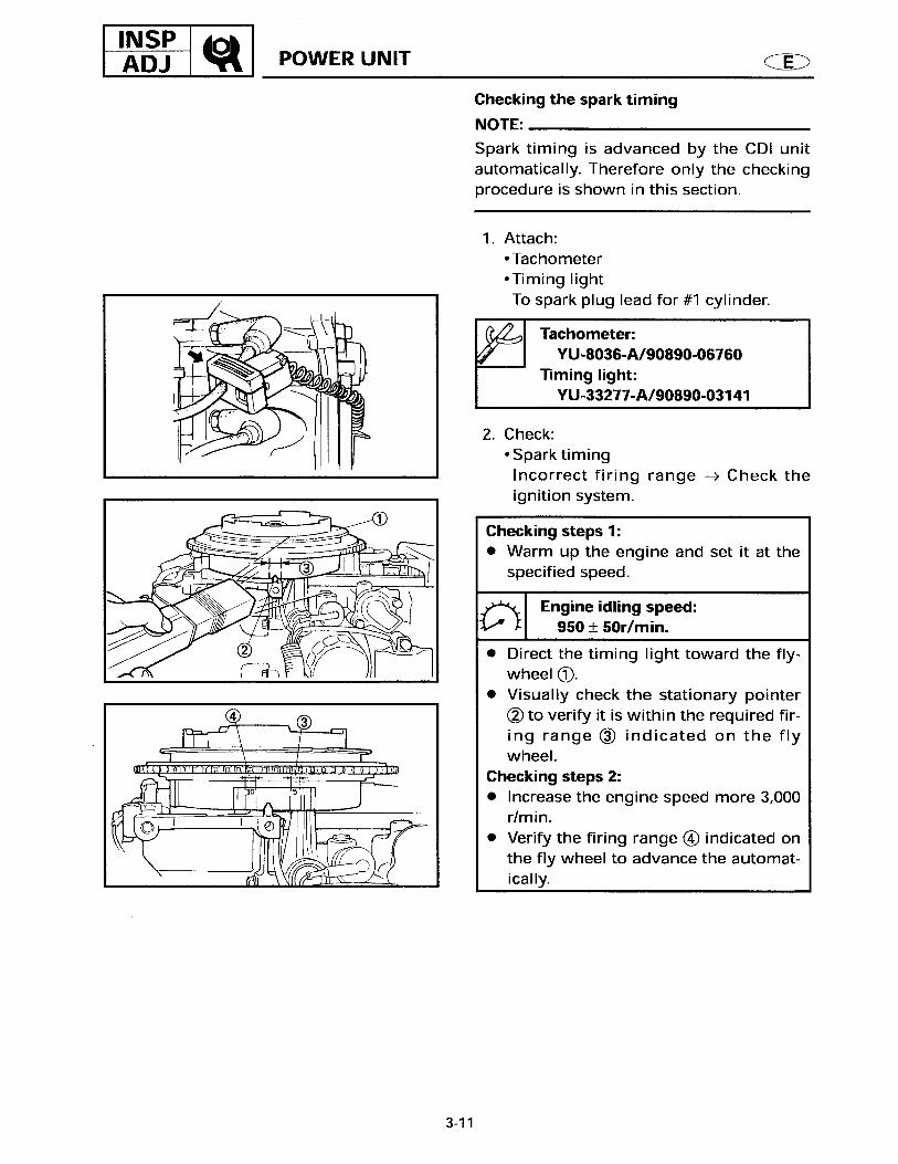
Type 4 stroke, OHC, in-lineNumber of cylinders 2Displacement cm3 (cu. in) 323 (19.7)Bore x stroke mm (in) 59.0 x 59.0 (2.32 x 2.32)Compression ratio 9.19Compression pressure kPa (kg/cm2, psi) 961 (9.8, 139.4)Number of carburetors 1Control system Remote control Tiller controlStarting system Electric motorIgnition control system C.D.ILighting coil Single phaseLighting coil output V-A DC12-10 with rectifier/regulatorStarting enrichment Choke valveSpark plug DPR6EA-9Exhaust system Propeller hubLubrication system Wet sumpIgnition timing Degree (BTDC) 5 – 30
FUEL AND OIL
Fuel type Unleaded regular gasolineFuel rating PON (*1) 86
PON (*2) 91(*1) PON : Pump Octane Number(*2) RON : Research Octane Number

GENERAL SPECIFICATIONS
4
Item Unit
ModelWorld wide F15AEP F15AEHP
USA F15PR F15PHCanada F15PR F15PH
Engine oil type 4-stroke engine oilEngine oil grade API SE, SF, SE-SF, SE-SF-CC
SAE 10W-30, 10W-40Engine oil quantity
With oil filter cm3 (US oz, Imp oz) 1,200 (40.6, 42.2)Without oil filter cm3 (US oz, Imp oz) 1,000 (33.8, 35.2)
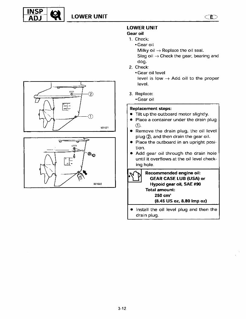
Gear oil type Hypoid gear oilGear oil grade SAE #90Gear oil quantity cm3 (US oz, Imp oz) 250 (8.45, 8.80)
BRACKET
Trim angle Degrees 8, 12, 16, 20Tilt-up angle Degrees 63Steering angle Degrees 40 + 40
DRIVE UNIT
Gear positions F - N - RGear ratio 2.08 (27:13)Gear type Spiral bevel gearPropeller direction (rear view) ClockwisePropeller drive system SplinePropeller series mark J
ELECTRICAL
Battery capacity Ah (kC) 40 (144)Cold cranking A 380

MAINTENANCE SPECIFICATIONS
5
MAINTENANCE SPECIFICATIONS
POWER UNIT
Item Unit
ModelWorld wide F15AEP F15AEHP
USA F15PR F15PHCanada F15PR F15PH
CYLINDER HEAD
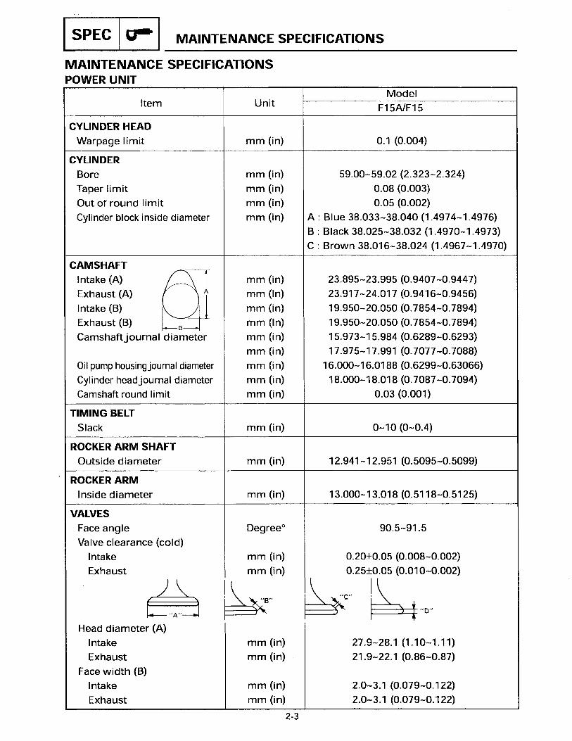
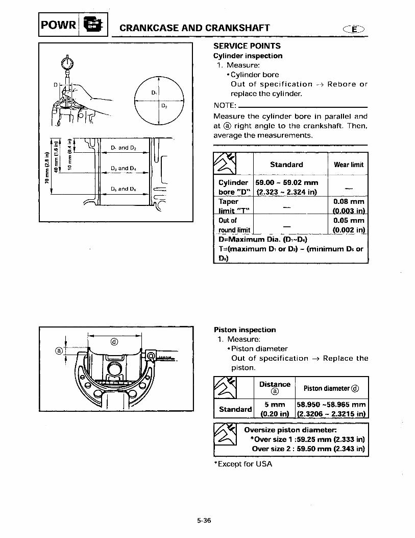
Warpage limit mm (in) 0.1 (0.004)CYLINDER
Bore mm (in) 59.000 - 59.015 (2.3228 - 2.3234)Taper limit mm (in) 0.08 (0.003)Out-of-round limit mm (in) 0.05 (0.002)Cylinder block inside diameter mm (in) A : Blue 38.033 - 38.040 (1.4974 - 1.4976)
B : Black 38.025 - 38.032 (1.4970 - 1.4973)C : Brown 38.016 - 38.024 (1.4967 - 1.4970)
CAMSHAFT
Intake (A) mm (in) 27.596 - 27.696 (1.0865 - 1.0904)Intake (B) mm (in) 23.95 - 24.05 (0.9429 - 0.9468)Exhaust (A) mm (in) 27.616 - 27.716 (1.0872 - 1.0912)Exhaust (B) mm (in) 23.95 - 24.05 (0.9429 - 0.9468)Cylinder head journal diameter (driven gear end)
mm (in) 17.973 - 17.984 (0.7076 - 0.7080)
Cylinder head journal diameter (center)
mm (in) 34.935 - 34.955 (1.3754 - 1.3762)
Oil pump housing journal diameter (oil pump end)
mm (in) 15.973 - 15.984 (0.6289 - 0.6293)
Camshaft round limit mm (in) 0.03 (0.001)TIMING BELT
Slack mm (in) 0 - 10 (0 - 0.4)ROCKER ARM SHAFT
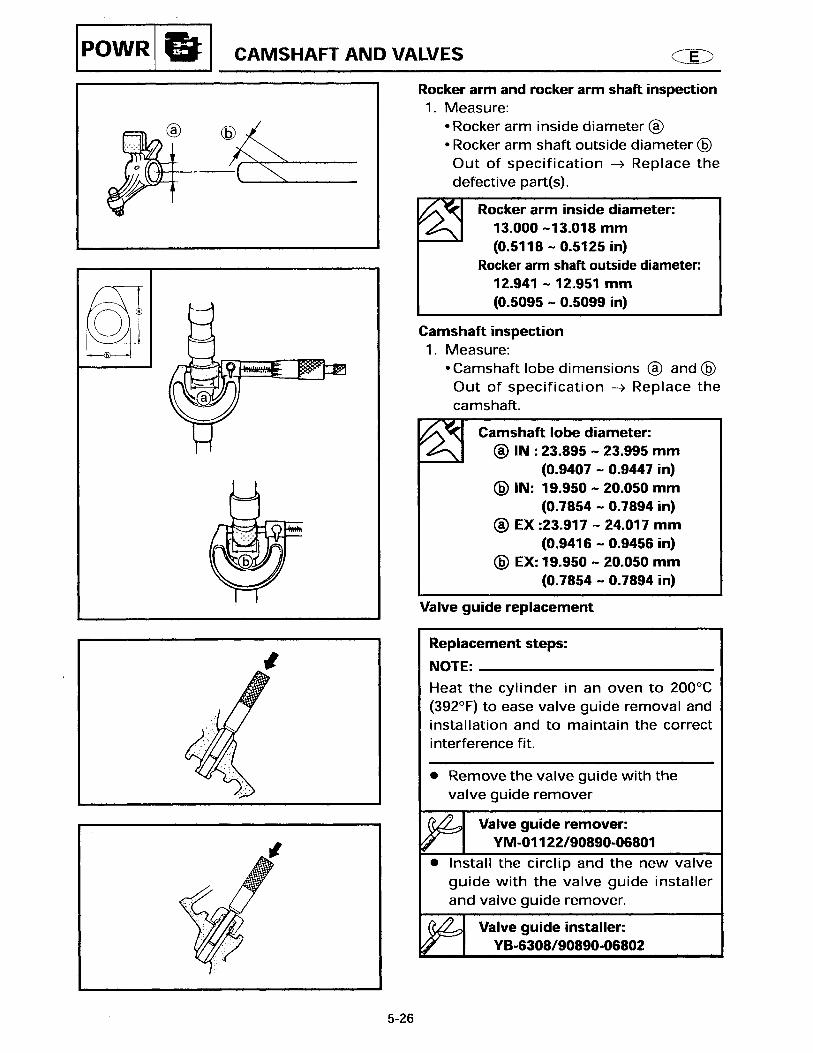
Outside diameter mm (in) 12.941 - 12.951 (0.5095 - 0.5099)ROCKER ARM
Inside diameter mm (in) 13.000 - 13.018 (0.5118 - 0.5125)VALVES
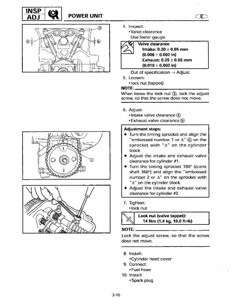
Face angle Degree 90.5 - 91.5Valve clearance (cold)
Intake mm (in) 0.15 - 0.25 (0.006 - 0.010)Exhaust mm (in) 0.20 - 0.30 (0.008 - 0.012)
Head diameter (A)Intake mm (in) 27.9 - 28.1 (1.10 - 1.11)Exhaust mm (in) 21.9 - 22.1 (0.86 - 0.87)
Face width (B)Intake mm (in) 2.0 - 3.1 (0.079 - 0.122)Exhaust mm (in) 2.0 - 3.1 (0.079 - 0.122)

MAINTENANCE SPECIFICATIONS
6
Item Unit
ModelWorld wide F15AEP F15AEHP
USA F15PR F15PHCanada F15PR F15PH
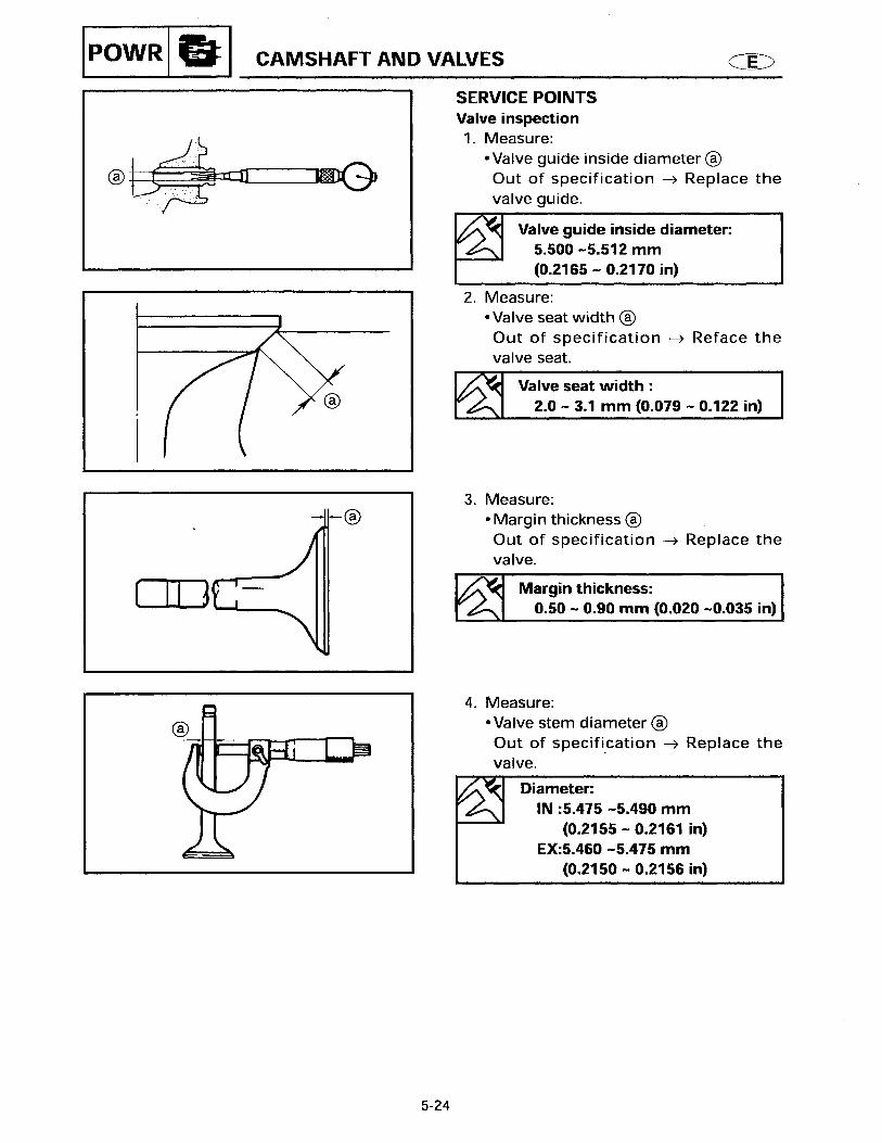
Seat width (C) mm (in) 0.6 - 0.8 (0.02 - 0.03)Margin thickness (D)
Intake mm (in) 0.50 - 0.90 (0.020 - 0.035)Exhaust mm (in) 0.50 - 0.90 (0.020 - 0.035)
Stem outside diameterIntake mm (in) 5.475 - 5.490 (0.2155 - 0.2161)Exhaust mm (in) 5.460 - 5.475 (0.2150 - 0.2156)
Guide inside diameter mm (in) 5.500 - 5.512 (0.2165 - 0.2170)Stem-to-guide clearance
Intake mm (in) 0.010 - 0.037 (0.0004 - 0.0015)Exhaust mm (in) 0.025 - 0.052 (0.0010 - 0.0020)
Stem runout limit mm (in) 0.016 (0.0006)VALVE SPRING
Free length mm (in) 34.4 (1.35)Free length limit mm (in) 32.7 (1.29)Set length mm/kg (in/lb) 25.4 / 11.0 (1.00 / 24.2)Tilt limit mm (in) 1.5 (0.06)
PISTON
Piston-to-cylinder clearance mm (in) 0.035 - 0.065 (0.0014 - 0.0026)Piston diameter (D)
Standard mm (in) 58.950 - 58.965 (2.3206 - 2.3215)Measuring point (H) mm (in) 5 (0.20)Pin boss inside diameter mm (in) 14.004 - 14.015 (0.5513 - 0.5518)Oversize piston diameter
1st (except for USA) mm (in) 59.25 (2.333)2nd mm (in) 59.50 (2.343)
PISTON PIN
Outside diameter mm (in) 13.996 - 14.000 (0.5510 - 0.5512)PISTON RINGS
Top ringType BarrelDimensions (B x T) mm (in) 1.2 x 2.25 (0.05 x 0.09)End gap (installed) mm (in) 0.15 - 0.30 (0.006 - 0.012)
Wear limit mm (in) 0.50 (0.020)Side clearance (installed) mm (in) 0.013 - 0.035 (0.0005 - 0.0013)
2nd ringType PlainDimensions (B x T) mm (in) 1.5 x 2.6 (0.06 x 0.10)End gap (installed) mm (in) 0.30 - 0.50 (0.012 - 0.020)
Wear limit mm (in) 0.70 (0.028)Side clearance (installed) mm (in) 0.02 - 0.04 (0.001 - 0.002)
MAINTENANCE SPECIFICATIONS
7
Item Unit
ModelWorld wide F15AEP F15AEHP
USA F15PR F15PHCanada F15PR F15PH
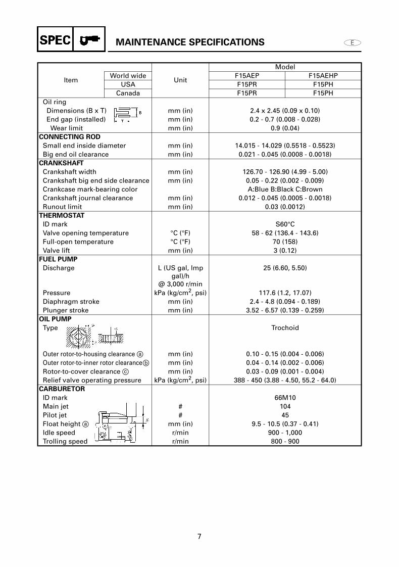
Oil ringDimensions (B x T) mm (in) 2.4 x 2.45 (0.09 x 0.10)End gap (installed) mm (in) 0.2 - 0.7 (0.008 - 0.028)
Wear limit mm (in) 0.9 (0.04)CONNECTING ROD
Small end inside diameter mm (in) 14.015 - 14.029 (0.5518 - 0.5523)Big end oil clearance mm (in) 0.021 - 0.045 (0.0008 - 0.0018)
CRANKSHAFT
Crankshaft width mm (in) 126.70 - 126.90 (4.99 - 5.00)Crankshaft big end side clearance mm (in) 0.05 - 0.22 (0.002 - 0.009)Crankcase mark-bearing color A:Blue B:Black C:BrownCrankshaft journal clearance mm (in) 0.012 - 0.045 (0.0005 - 0.0018)Runout limit mm (in) 0.03 (0.0012)
THERMOSTAT
ID mark S60°CValve opening temperature °C (°F) 58 - 62 (136.4 - 143.6)Full-open temperature °C (°F) 70 (158)Valve lift mm (in) 3 (0.12)
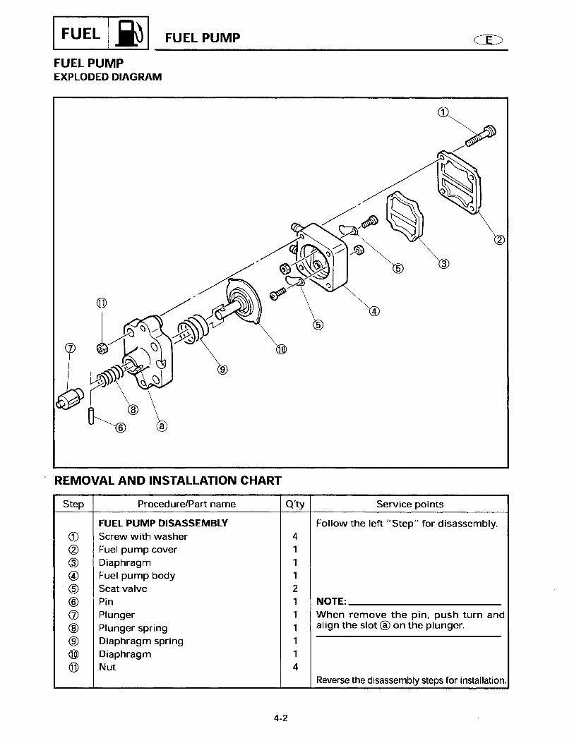
FUEL PUMP
Discharge L (US gal, lmp gal)/h
@ 3,000 r/min
25 (6.60, 5.50)
Pressure kPa (kg/cm2, psi) 117.6 (1.2, 17.07)Diaphragm stroke mm (in) 2.4 - 4.8 (0.094 - 0.189)Plunger stroke mm (in) 3.52 - 6.57 (0.139 - 0.259)
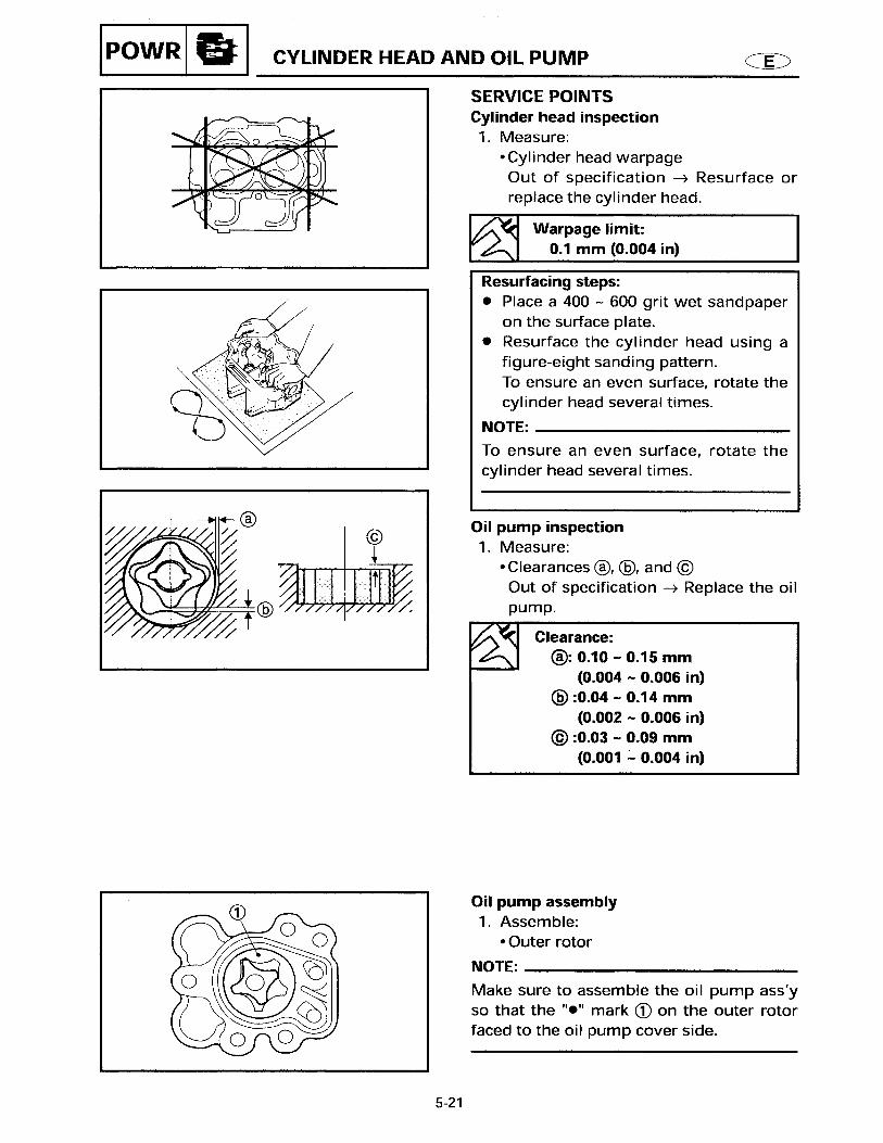
OIL PUMP
Type Trochoid
Outer rotor-to-housing clearance a mm (in) 0.10 - 0.15 (0.004 - 0.006)Outer rotor-to-inner rotor clearanceb mm (in) 0.04 - 0.14 (0.002 - 0.006)Rotor-to-cover clearance c mm (in) 0.03 - 0.09 (0.001 - 0.004)Relief valve operating pressure kPa (kg/cm2, psi) 388 - 450 (3.88 - 4.50, 55.2 - 64.0)
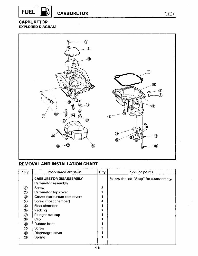
CARBURETOR
ID mark 66M10Main jet # 104Pilot jet # 45Float height a mm (in) 9.5 - 10.5 (0.37 - 0.41)Idle speed r/min 900 - 1,000Trolling speed r/min 800 - 900

MAINTENANCE SPECIFICATIONS
8
LOWER
ELECTRICAL
Item Unit
ModelWorld wide F15AEP F15AEHP
USA F15PR F15PHCanada F15PR F15PH
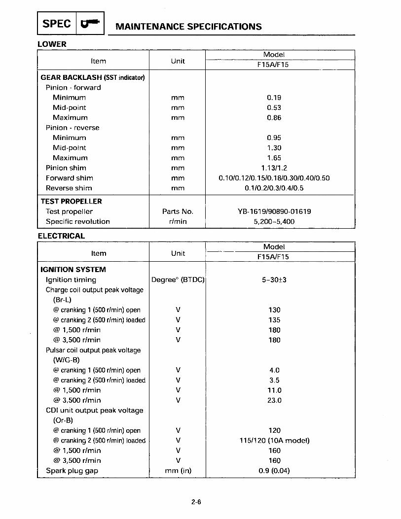
GEAR BACKLASH (SST indicator)
Pinion-forwardMinimum mm (in) 0.19 (0.007)Mid-point mm (in) 0.53 (0.02)Maximum mm (in) 0.86 (0.034)
Pinion-reverseMinimum mm (in) 0.95 (0.037)Mid-point mm (in) 1.30 (0.051)Maximum mm (in) 1.65 (0.064)
Pinion shim mm 1.13 / 1.2Forward shim mm 0.10 / 0.12 / 0.15 / 0.18 / 0.30 / 0.40 / 0.50Reverse shim mm 0.1 / 0.2 / 0.3 / 0.4 / 0.5
TEST PROPELLER
Test propeller Part no. YB - 1619 / 90890-01619Specific revolution r/min 5,200 - 5,400
Item Unit
ModelWorld wide F15AEP F15AEHP
USA F15PR F15PHCanada F15PR F15PH
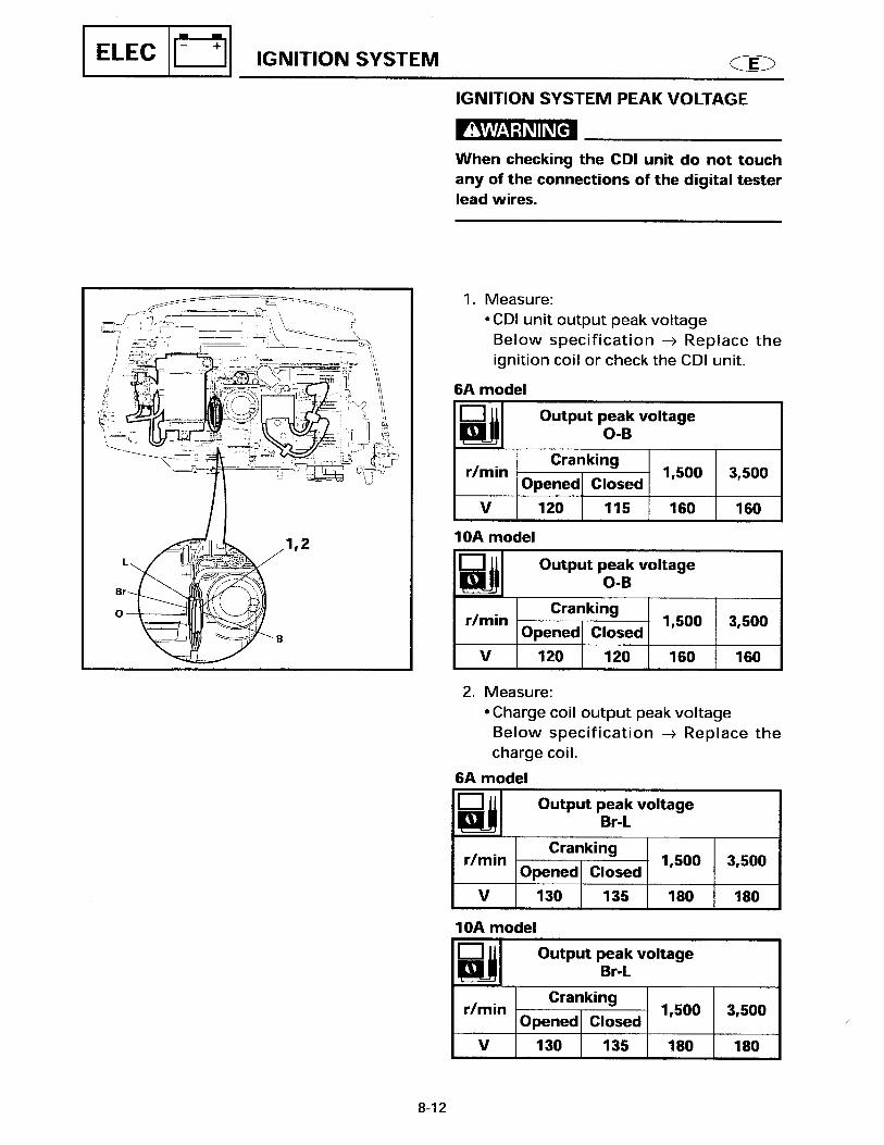
IGNITION SYSTEM
Ignition timing Degree 5 - 30Charge coil output peak voltage (BTDC)
(Br-L)@ cranking 1 (500 r/min) open V 130@ cranking 2 (500 r/min) loaded V 130@ 1,500 r/min V 180@ 3,500 r/min V 180
Pulser coil output peak voltage(W/G-B)@ cranking 1 (500 r/min) open V 4.0@ cranking 2 (500 r/min) loaded V 3.5@ 1,500 r/min V 11.0@ 3,500 r/min V 23.0
CDI unit output peak voltage(O-B)@ cranking 1 (500 r/min) open V 120@ cranking 2 (500 r/min) loaded V 120@ 1,500 r/min V 165@ 3,500 r/min V 165
Spark plug gap mm (in) 0.9 (0.04)

MAINTENANCE SPECIFICATIONS
9
Item Unit
ModelWorld wide F15AEP F15AEHP
USA F15PR F15PHCanada F15PR F15PH
Charge coil resistance (Br-L) Ω 272 - 408Pulser coil resistance (W/G-B) Ω 234 - 348Ignition coil resistance (O-B)
Primary Ω 0.16 - 0.24Secondary kΩ 3.92 - 5.88
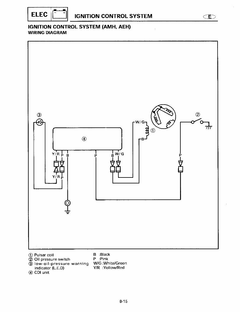
IGNITION CONTROL SYSTEM
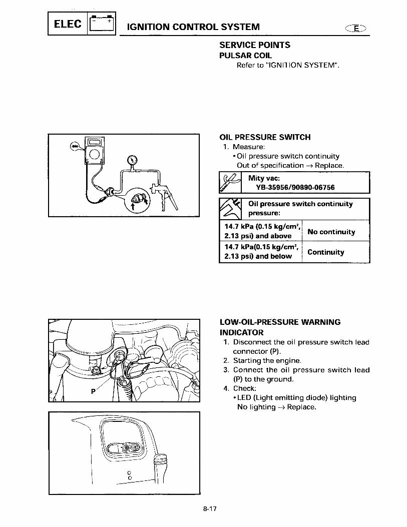
Oil pressure switch kPa (kg/cm2, psi) 14.7 (0.15, 2.13)Engine speed limiter
Rated timing r/min 6,200Ignition off r/min 6,800Reset r/min 6,000
STARTING SYSTEM
Fuse A 20STARTER MOTOR
Type BendixRating Second 30Output kW 1.1Brush length mm (in) 12.6 (0.5)
Limit mm (in) 6.4 (0.25)Commutator undercut mm (in) 2 (0.08)
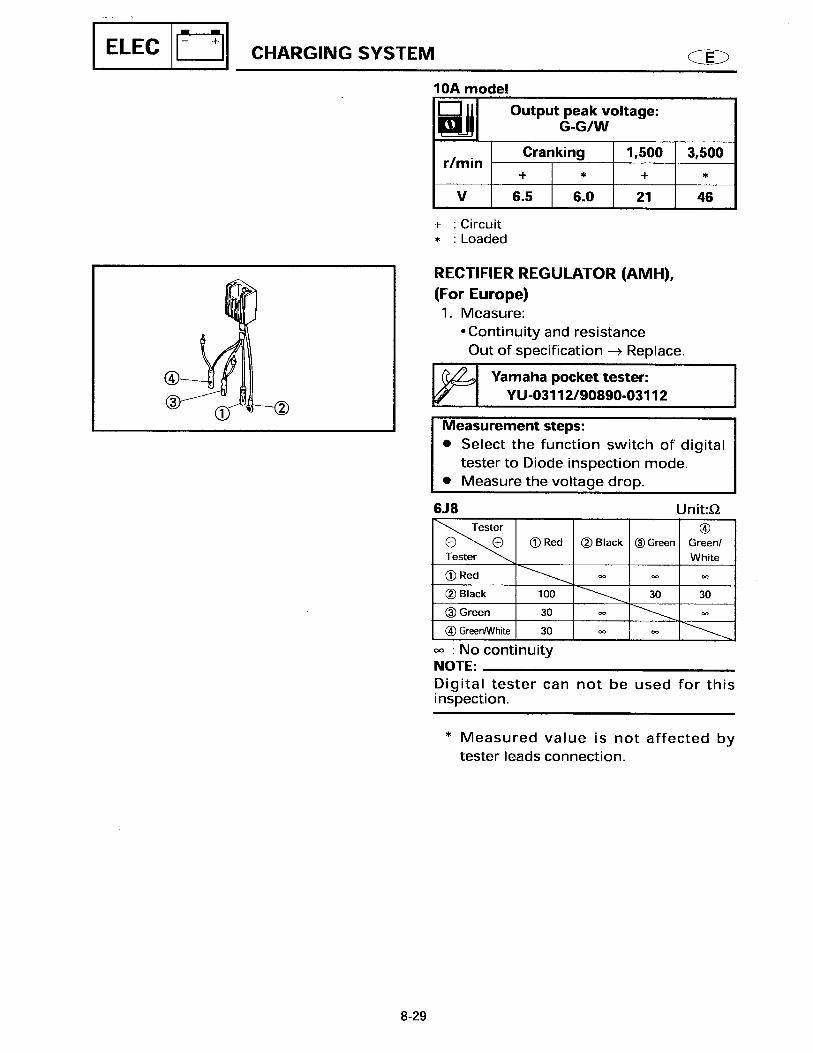
Limit mm (in) 0.8 (0.03)CHARGING SYSTEM
Lighting coil output peak voltageV1 (G-G/W)@ cranking 1 (500 r/min) open V 6.5@ cranking 2 (500 r/min) loaded V 6.0@ 1,500 r/min V 21@ 3,500 r/min V 46
Rectifier output peak voltageV2 (R-B)@ cranking (500 r/min) open V 6.0@ 1,500 r/min V 20@ 3,500 r/min V 45
Charging current A@ r/min 10 @ 5,000Lighting coil resistance (G-G/W) Ω@20°C (68°F) 0.24 - 0.36

MAINTENANCE SPECIFICATIONS
10
Item Unit
ModelWorld wide F15AEP F15AEHP
USA F15PR F15PHCanada F15PR F15PH
POWER TILT (PT) UNIT
Fluid type ATF Dexroin llBrush length mm (in) 6 (0.25)
Limit mm (in) 3 (0.12)Commutator diameter mm (in) 16.5 (0.65)
Limit mm (in) 15.5 (0.61)
MAINTENANCE SPECIFICATIONS
11
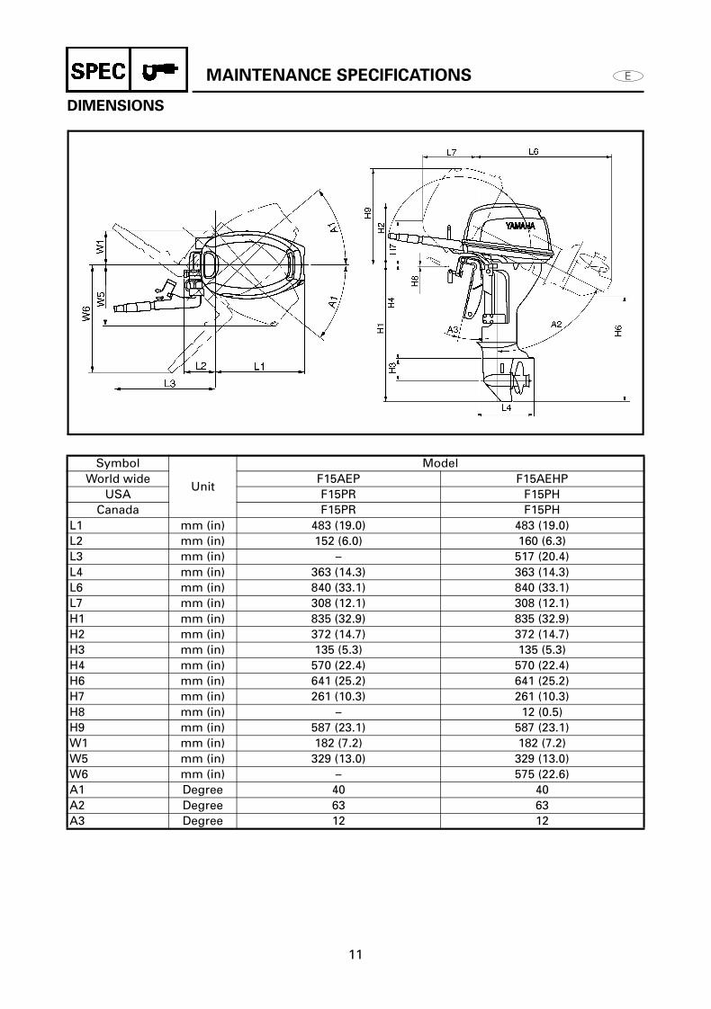
DIMENSIONS
Symbol
Unit
ModelWorld wide F15AEP F15AEHP
USA F15PR F15PHCanada F15PR F15PH
L1 mm (in) 483 (19.0) 483 (19.0)L2 mm (in) 152 (6.0) 160 (6.3)L3 mm (in) – 517 (20.4)L4 mm (in) 363 (14.3) 363 (14.3)L6 mm (in) 840 (33.1) 840 (33.1)L7 mm (in) 308 (12.1) 308 (12.1)H1 mm (in) 835 (32.9) 835 (32.9)H2 mm (in) 372 (14.7) 372 (14.7)H3 mm (in) 135 (5.3) 135 (5.3)H4 mm (in) 570 (22.4) 570 (22.4)H6 mm (in) 641 (25.2) 641 (25.2)H7 mm (in) 261 (10.3) 261 (10.3)H8 mm (in) – 12 (0.5)H9 mm (in) 587 (23.1) 587 (23.1)W1 mm (in) 182 (7.2) 182 (7.2)W5 mm (in) 329 (13.0) 329 (13.0)W6 mm (in) – 575 (22.6)A1 Degree 40 40A2 Degree 63 63A3 Degree 12 12
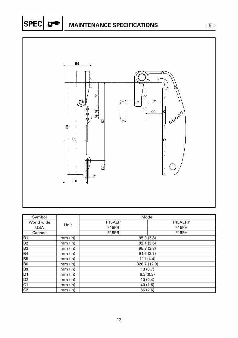
MAINTENANCE SPECIFICATIONS
12
Symbol
Unit
ModelWorld wide F15AEP F15AEHP
USA F15PR F15PHCanada F15PR F15PH
B1 mm (in) 95.3 (3.8)B2 mm (in) 92.4 (3.6)B3 mm (in) 95.3 (3.8)B4 mm (in) 94.5 (3.7)B5 mm (in) 111 (4.4)B6 mm (in) 326.7 (12.9)B9 mm (in) 18 (0.7)D1 mm (in) 8.3 (0.3)D2 mm (in) 10 (0.4)C1 mm (in) 40 (1.6)C2 mm (in) 66 (2.6)
TIGHTENING TORQUES
13
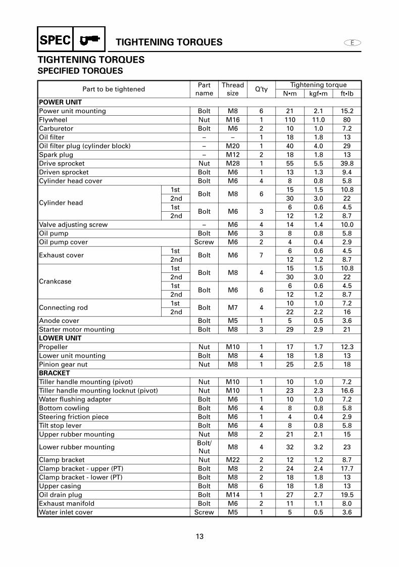
TIGHTENING TORQUES
SPECIFIED TORQUES
Part to be tightenedPart
nameThread
sizeQ’ty
Tightening torqueN•m kgfm ftlb
POWER UNIT
Power unit mounting Bolt M8 6 21 2.1 15.2Flywheel Nut M16 1 110 11.0 80Carburetor Bolt M6 2 10 1.0 7.2Oil filter – – 1 18 1.8 13Oil filter plug (cylinder block) – M20 1 40 4.0 29Spark plug – M12 2 18 1.8 13Drive sprocket Nut M28 1 55 5.5 39.8Driven sprocket Bolt M6 1 13 1.3 9.4Cylinder head cover Bolt M6 4 8 0.8 5.8
Cylinder head
1stBolt M8 6
15 1.5 10.82nd 30 3.0 221st
Bolt M6 36 0.6 4.5
2nd 12 1.2 8.7Valve adjusting screw – M6 4 14 1.4 10.0Oil pump Bolt M6 3 8 0.8 5.8Oil pump cover Screw M6 2 4 0.4 2.9
Exhaust cover1st
Bolt M6 76 0.6 4.5
2nd 12 1.2 8.7
Crankcase
1stBolt M8 4
15 1.5 10.82nd 30 3.0 221st
Bolt M6 66 0.6 4.5
2nd 12 1.2 8.7
Connecting rod1st
Bolt M7 410 1.0 7.2
2nd 22 2.2 16Anode cover Bolt M5 1 5 0.5 3.6Starter motor mounting Bolt M8 3 29 2.9 21LOWER UNIT
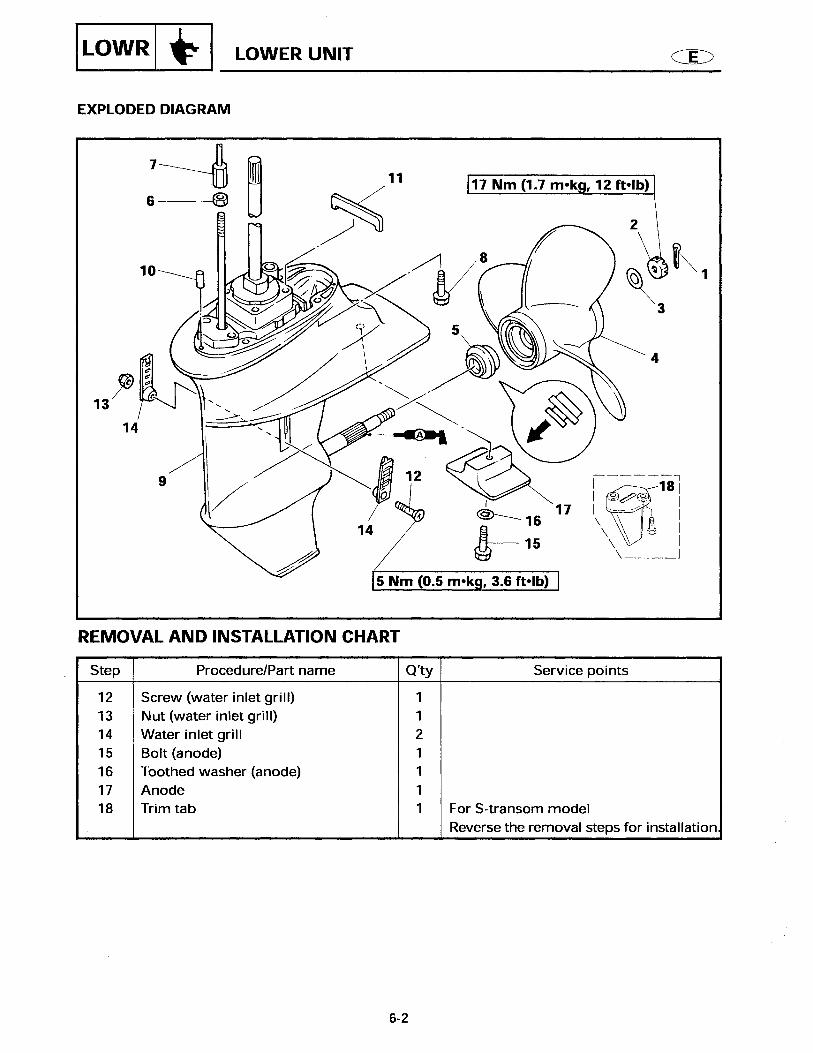
Propeller Nut M10 1 17 1.7 12.3Lower unit mounting Bolt M8 4 18 1.8 13Pinion gear nut Nut M8 1 25 2.5 18BRACKET
Tiller handle mounting (pivot) Nut M10 1 10 1.0 7.2Tiller handle mounting locknut (pivot) Nut M10 1 23 2.3 16.6Water flushing adapter Bolt M6 1 10 1.0 7.2Bottom cowling Bolt M6 4 8 0.8 5.8Steering friction piece Bolt M6 1 4 0.4 2.9Tilt stop lever Bolt M6 4 8 0.8 5.8Upper rubber mounting Nut M8 2 21 2.1 15
Lower rubber mountingBolt/Nut
M8 4 32 3.2 23
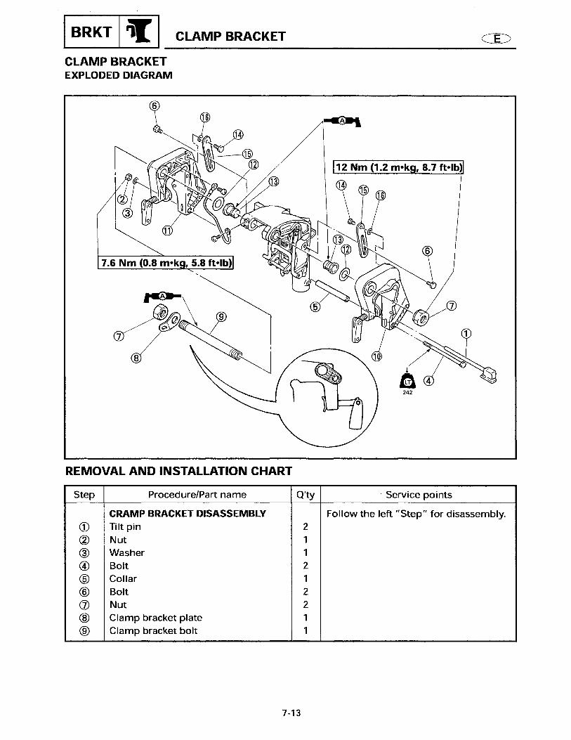
Clamp bracket Nut M22 2 12 1.2 8.7Clamp bracket - upper (PT) Bolt M8 2 24 2.4 17.7Clamp bracket - lower (PT) Bolt M8 2 18 1.8 13Upper casing Bolt M8 6 18 1.8 13Oil drain plug Bolt M14 1 27 2.7 19.5Exhaust manifold Bolt M6 2 11 1.1 8.0Water inlet cover Screw M5 1 5 0.5 3.6

TIGHTENING TORQUES
14
GENERAL TORQUES
This chart specifies tightening torques for standard fasteners with a standard ISO thread pitch. Tightening torque specifications for special components or assemblies are provided in applicable sections of this manual. To avoid warpage, tighten multifastener assemblies in a crisscross fashion and progressive stages until the specified tightening torque is reached. Unless otherwise specified, tightening torque specifications require clean, dry threads.Components should be at room temperature.
Part to be tightenedPart
nameThread
sizeQ’ty
Tightening torqueN•m kgfm ftlb
PT UNIT
Reservoir cap Bolt M10 1 5 0.5 3.6PT motor Bolt M5 4 5 0.5 3.6Cylinder end screw Screw M33 1 45 4.5 32Gear pump housing Bolt M5 6 5 0.5 3.6Tilt piston – M12 1 45 4.5 32ELECTRICAL
Starter motor Bolt M8 3 29 2.9 21Solenoid Screw M5 2 3 0.3 2.2Solenoid mount bracket Bolt M6 2 8 0.8 5.8Lighting coil Bolt M6 4 8 0.8 5.8Oil pressure switch Bolt – 1 8 0.8 5.8Rectifier/regulator Bolt M6 2 8 0.8 5.8Rectifier/regulator bracket Bolt M6 3 8 0.8 5.8Rectifier/regulator bracket ground Bolt M6 1 8 0.8 5.8
Nut (A) Bolt (B)General torque specifications
N•m kgf•m ftlb8 mm M5 5 0.5 3.610 mm M6 8 0.8 5.812 mm M8 18 1.8 1314 mm M10 36 3.6 2517 mm M12 43 4.3 31
MAINTENANCE INTERVAL CHART
15
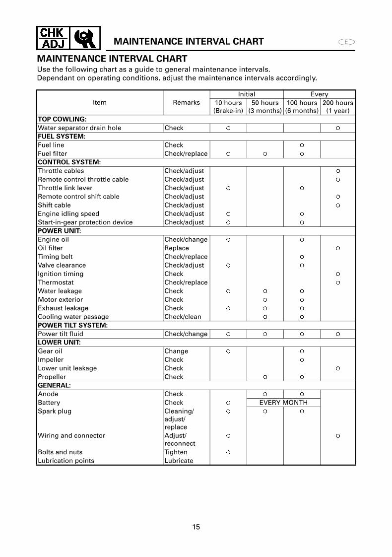
MAINTENANCE INTERVAL CHARTUse the following chart as a guide to general maintenance intervals.Dependant on operating conditions, adjust the maintenance intervals accordingly.
Item RemarksInitial Every
10 hours (Brake-in)
50 hours (3 months)
100 hours (6 months)
200 hours (1 year)
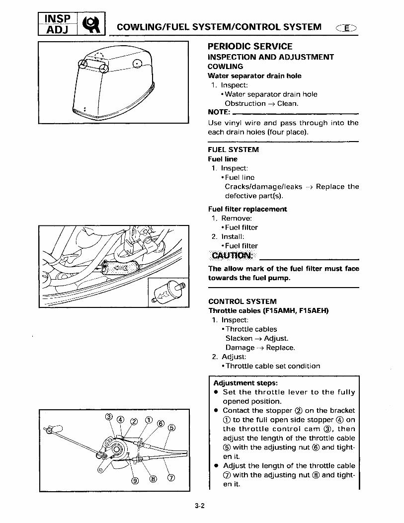
TOP COWLING:
Water separator drain hole Check FUEL SYSTEM:
Fuel line Check Fuel filter Check/replace CONTROL SYSTEM:
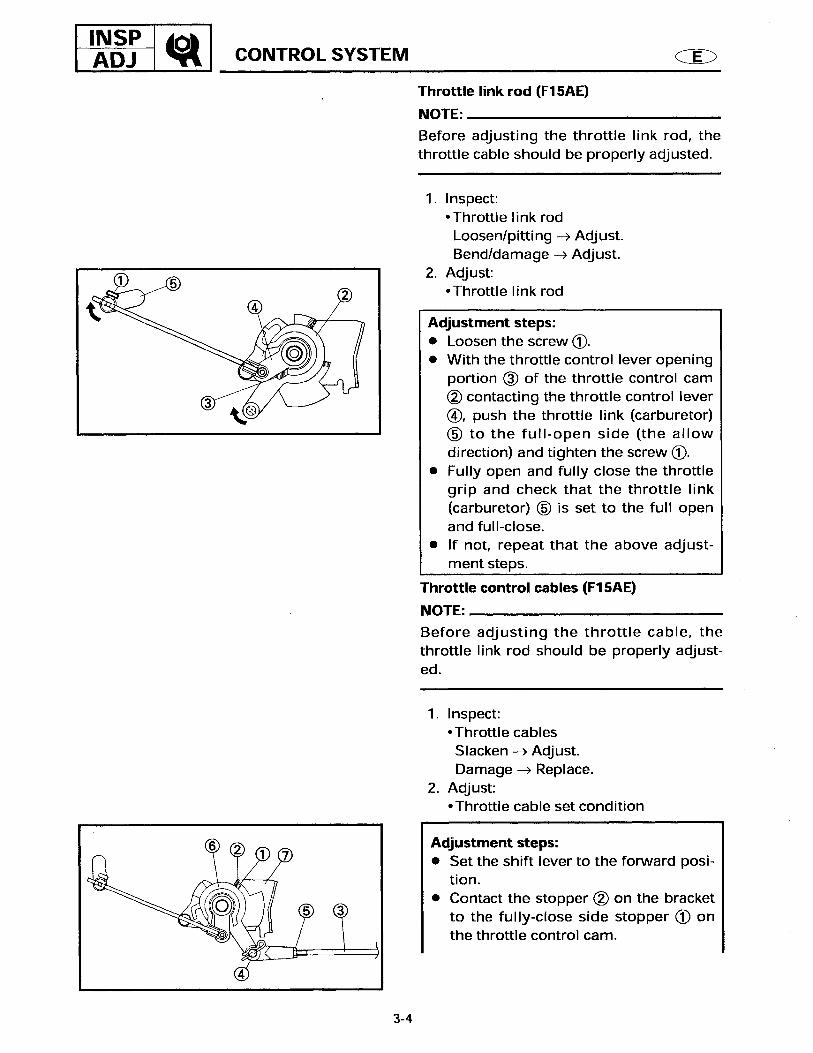
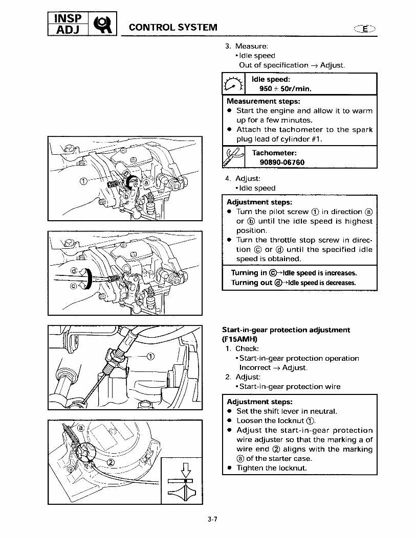
Throttle cables Check/adjust Remote control throttle cable Check/adjust Throttle link lever Check/adjust Remote control shift cable Check/adjust Shift cable Check/adjust Engine idling speed Check/adjust Start-in-gear protection device Check/adjust POWER UNIT:
Engine oil Check/change Oil filter Replace Timing belt Check/replace Valve clearance Check/adjust Ignition timing Check Thermostat Check/replace Water leakage Check Motor exterior Check Exhaust leakage Check Cooling water passage Check/clean POWER TILT SYSTEM:
Power tilt fluid Check/change LOWER UNIT:
Gear oil Change Impeller Check Lower unit leakage Check Propeller Check GENERAL:
Anode Check Battery Check EVERY MONTHSpark plug Cleaning/
adjust/ replace
Wiring and connector Adjust/reconnect
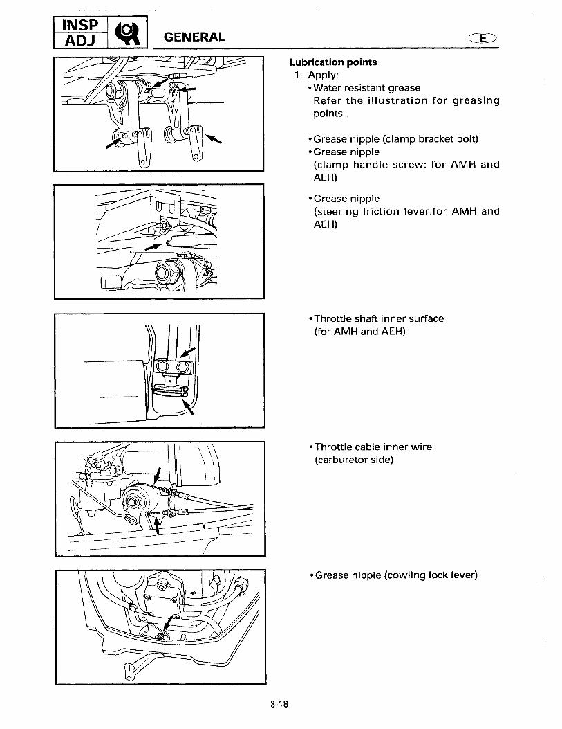
Bolts and nuts Tighten Lubrication points Lubricate

POWER TILT SYSTEM/ GENERAL
16
POWER TILT SYSTEM/ GENERAL
CHECKING THE POWER TILT (PT)
FLUID LEVEL
WARNING
To prevent the hydraulic fluid from
spurting out due to internal pressure, the
outboard should be kept fully tilted up (the
tilt ram at full length) while slowly
removing the screw.
1. Check: Power tilt fluid level
Level is low Add fluid to the proper level.
Checking steps:
(1) Tilt up the outboard and lock it with tilt lock knob 1.
(2) Remove the reservoir cap 2.(3) Check that the fluid level is directly
below the fluid level checking hole a.
2. Add:
GENERAL
CHECKING THE ANODE
1. Check: Anode (engine) Anode (clamp bracket) Anode (lower unit)
Scales Clean.Oil/grease Clean.Excessive wear (half worn) damage Replace.
CAUTION:
Do not oil, grease, or paint the anode, or it
will not operate properly.
Recommended hydraulic fluid:
ATF Dexron ll
Reservoir cap:
5 N•m (0.5 kgf•m, 3.6ft•lb)
POWER UNIT
17
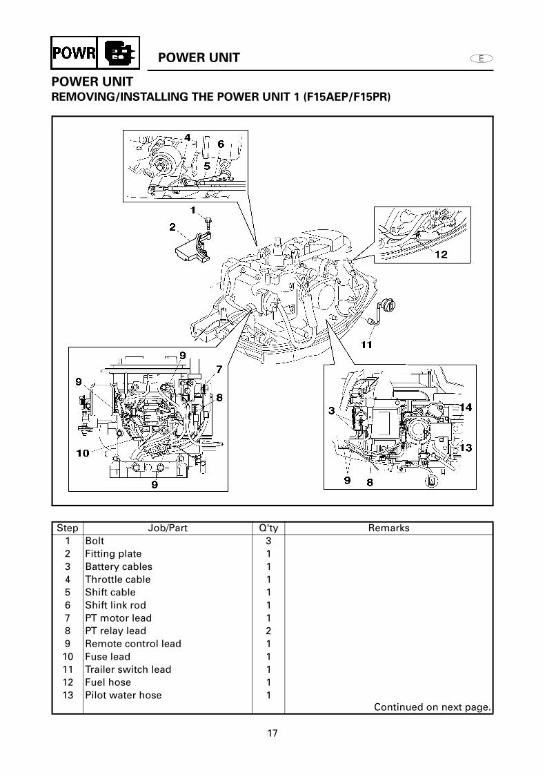
POWER UNIT
REMOVING/INSTALLING THE POWER UNIT 1 (F15AEP/F15PR)
Step Job/Part Q'ty Remarks1 Bolt 32 Fitting plate 13 Battery cables 14 Throttle cable 15 Shift cable 16 Shift link rod 17 PT motor lead 18 PT relay lead 29 Remote control lead 110 Fuse lead 111 Trailer switch lead 112 Fuel hose 113 Pilot water hose 1
Continued on next page.

POWER UNIT
18
Step Job/Part Q'ty Remarks14 Water flushing hose 1
For installation, reverse the removal procedure.

POWER UNIT
19
REMOVING/INSTALLING THE POWER UNIT 1 (F15AEHP/F15PH)
Step Job/Part Q'ty Remarks1 Bolt 32 Fitting plate 13 Battery cables 14 Throttle cable 25 Shift link rod 16 PT motor lead 17 PT relay lead 28 Engine stop switch lead 19 Neutral switch lead 110 Fuse lead 111 Trailer switch lead 1 (With trailer switch model only)12 Fuel hose 113 Pilot water hose 1
Continued on next page.

POWER UNIT
20
Step Job/Part Q'ty Remarks14 Water flushing hose 1
For installation, reverse the removal procedure.
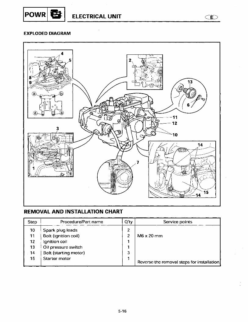
ELECTRICAL UNIT
21
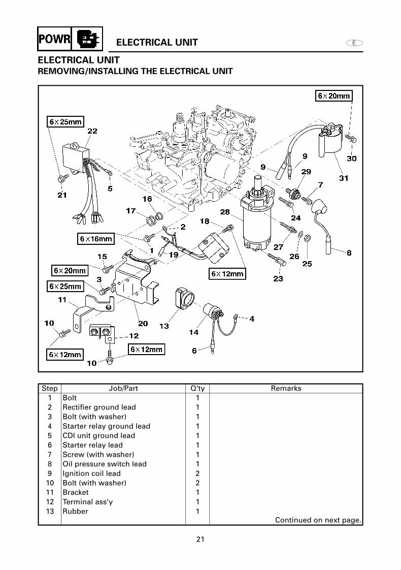
ELECTRICAL UNIT
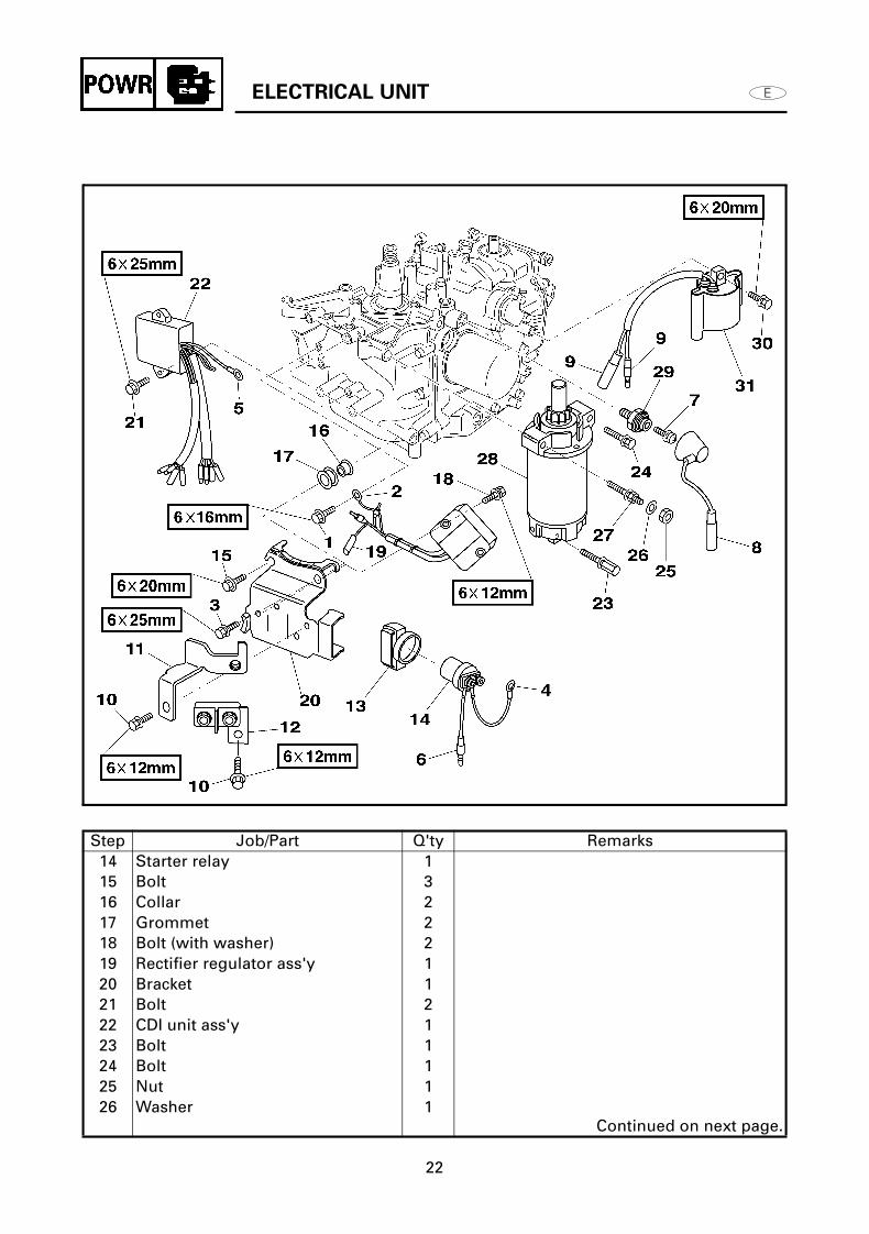
REMOVING/INSTALLING THE ELECTRICAL UNIT
Step Job/Part Q'ty Remarks1 Bolt 12 Rectifier ground lead 13 Bolt (with washer) 14 Starter relay ground lead 15 CDI unit ground lead 16 Starter relay lead 17 Screw (with washer) 18 Oil pressure switch lead 19 Ignition coil lead 210 Bolt (with washer) 211 Bracket 112 Terminal ass'y 113 Rubber 1
Continued on next page.
ELECTRICAL UNIT
22
Step Job/Part Q'ty Remarks14 Starter relay 115 Bolt 316 Collar 217 Grommet 218 Bolt (with washer) 219 Rectifier regulator ass'y 120 Bracket 121 Bolt 222 CDI unit ass'y 123 Bolt 124 Bolt 125 Nut 126 Washer 1
Continued on next page.

ELECTRICAL UNIT
23
Step Job/Part Q'ty Remarks27 Bolt 128 Starter motor 129 Oil pressure switch 130 Bolt (with washer) 231 Ignition coil ass’y 1
For installation, reverse the removal procedure.

CYLINDER HEAD AND OIL PUMP
24
CYLINDER HEAD AND OIL PUMP
REMOVING/INSTALLING THE CYLINDER HEAD AND OIL PUMP
Step Job/Part Q'ty Remarks1 Spark plug 22 Bolt (with washer) 43 Cylinder head cover 14 O-ring 1 Not reusable5 Bolt (with washer) 36 Bolt 67 Cylinder head assembly 18 Dowel pin 29 Gasket 1 Not reusable10 Bolt (with washer) 311 Oil pump 112 Oil pump gasket 1 Not reusable
For installation, reverse the removal procedure.

OIL PUMP
25
OIL PUMP
DISASSEMBLING/ASSEMBLING THE OIL PUMP
Step Job/Part Q'ty Remarks1 Screw 22 Oil pump cover 13 O-ring 1 Not reusable4 Inner rotor 15 Shaft 16 Pin 17 Outer rotor 18 Oil pump housing 1
For installation, reverse the removal procedure.

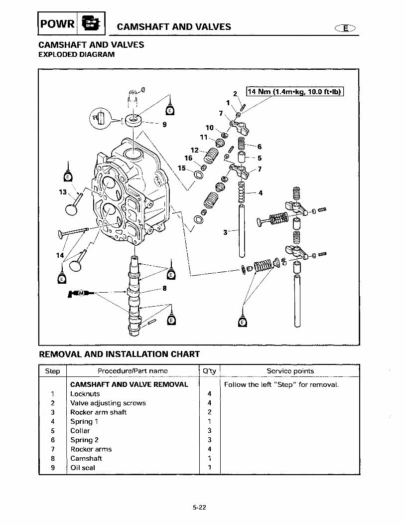
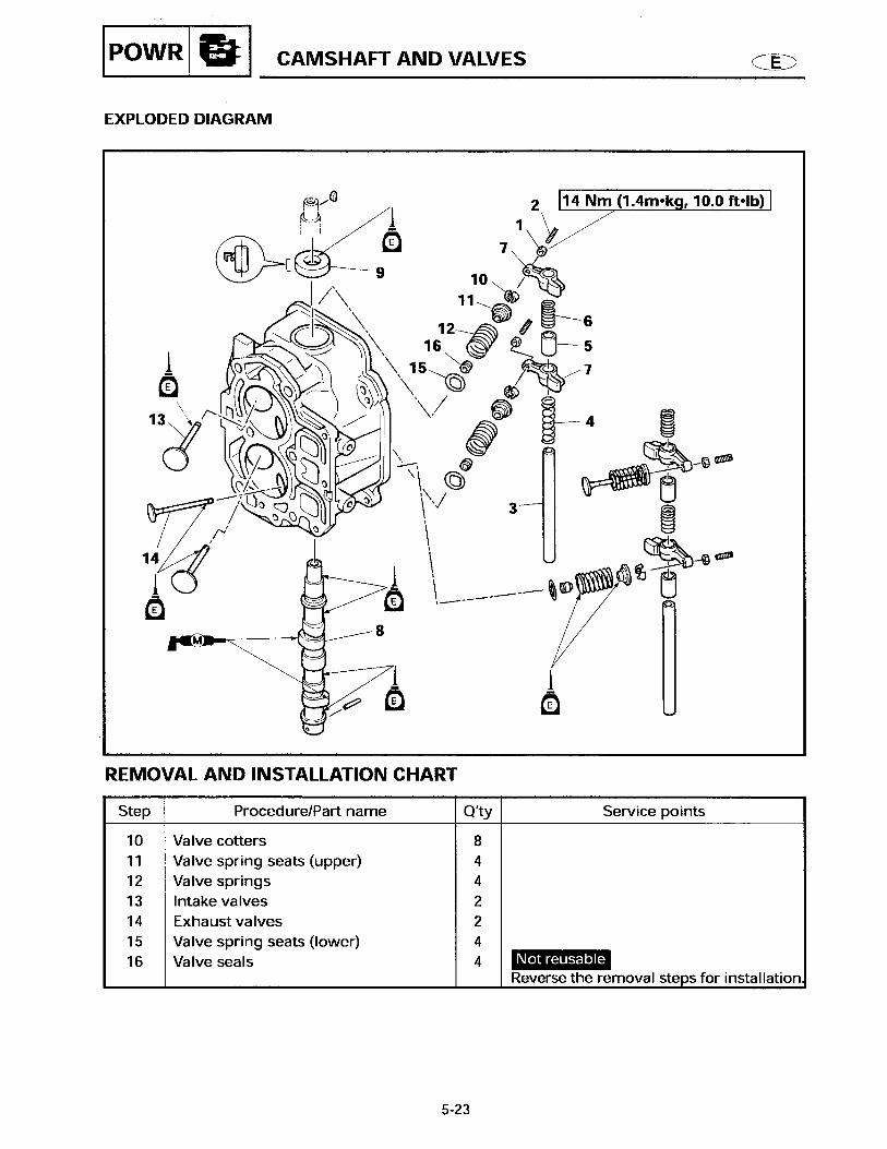
CAMSHAFT AND VALVE
26
CAMSHAFT AND VALVE
REMOVING/INSTALLING THE CAMSHAFT AND VALVE
Step Job/Part Q'ty Remarks1 Locknut 42 Valve adjusting screw 43 Rocker arm shaft 24 Spring 1 15 Spring 2 36 Collar 1 Length: 15.0 mm (0.59 in)7 Collar 1 Length: 22.5 mm (0.89 in)8 Collar 1 Length: 8.5 mm (0.33 in)9 Rocker arm 410 Camshaft 111 Valve cotter 812 Valve spring seat (upper) 413 Valve spring 4
Continued on next page.

CAMSHAFT AND VALVE
27
Step Job/Part Q'ty Remarks14 Intake valve 215 Exhaust valve 216 Valve spring seat (lower) 417 Valve seal 4 Not reusable18 Oil seal 1 Not reusable19 Cylinder head 1
For installation, reverse the removal procedure.

CAMSHAFT AND VALVE
28
CHECKING THE CAMSHAFT
Measure: Camshaft lobe diameter a and b
Out of specification Replace the camshaft
Rocker arm inside diameter:
IN a: 27.596 - 27.696 mm
(1.0865 - 1.0904 in)
IN b: 23.95 - 24.05 mm
(0.9429 - 0.9468 in)
EX a: 27.616 - 27.716 mm
(1.0872 - 1.0912 in)
EX b: 23.95 - 24.05 mm
(0.9429 - 0.9468 in)

CAMSHAFT AND VALVE
29
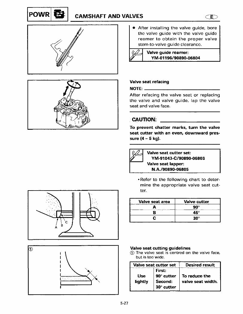
REFACING THE VALVE SEAT
Reface: Valve seat
CAUTION:
When turning the valve seat cutter, keep
an even downward pressure (4 - 5 kg) to
prevent chatter mark.
NOTE:After refacing the valve seat, lap the valve seat and valve face.
Refacing steps:
A Valve seat is centered on valve face butit is too wide.
Valve seat width
(intake valve and exhaust valve):
0.6 - 0.8 mm (0.02 - 0.03 in)
Valve seat cutter set:
90890-06803
Valve seat cutter:
90890-06556
Valve seat lapper:
90890-06805
Cut section and seat cutterSeat Cut section Seat cutter
INa: 180° 180°: 90890-06556b: 90° 90°: 90890-06312c: 60° 60°: 90890-06315
EXa: 180° 170°: 90890-06313b: 90° 90°: 90890-06312c: 0° 60°: 90890-06315
Valve seat cutter Desired result
a 180° cutter (IN)170° cutter (EX)
Lap the face a and face c lightly to reduce the valve seat width.c 60° cutter (IN/EX)
EX
a
c
b
IN
a
c
b
AI N
E X
a
ca
a
c
c
CAMSHAFT AND VALVE
30
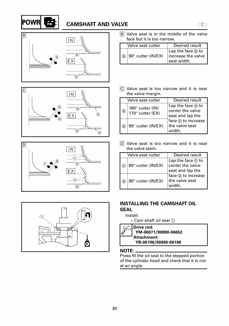
B Valve seat is in the middle of the valveface but it is too narrow.
C Valve seat is too narrow and it is nearthe valve margin.
D Valve seat is too narrow and it is nearthe valve stem.
INSTALLING THE CAMSHAFT OIL
SEAL
Install: Cam shaft oil seal 1
NOTE:Press fit the oil seal to the stepped portion of the cylinder head and check that it is not at an angle.
Valve seat cutter Desired result
b 90° cutter (IN/EX)Lap the face b to increase the valve seat width.
Valve seat cutter Desired result
a 180° cutter (IN)170° cutter (EX)
Lap the face a to center the valve seat and lap the face b to increase the valve seat width.
b 90° cutter (IN/EX)
Valve seat cutter Desired result
c 60° cutter (IN/EX)Lap the face c to center the valve seat and lap the face b to increase the valve seat width.
b 90° cutter (IN/EX)
Drive rod:
YM-06071/90890-06652
Attachment:
YB-06196/90890-06196
BI N
E Xb
b
b
CI N
E Xa
b
a
ab
b
DI N
E X
bc
c
b
b
c

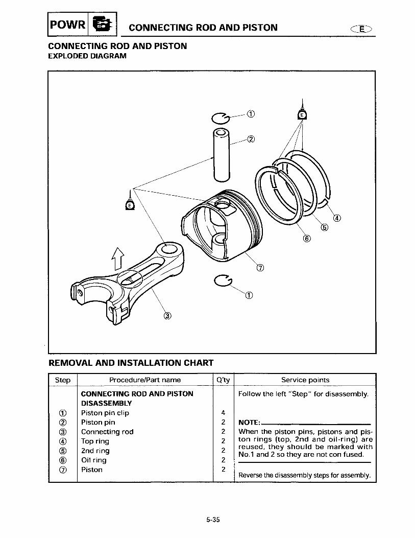
OIL FILTER, THERMOSTAT AND EXHAUST COVER
31
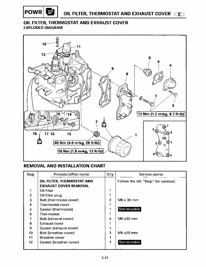
OIL FILTER, THERMOSTAT AND EXHAUST COVER
DISASSEMBLING/ASSEMBLING THE OIL FILTER, THERMOSTAT AND EXHAUST COVER
Step Job/Part Q'ty Remarks1 Oil filter 12 Oil filter plug 13 Bolt (with washer) 24 Thermostat cover 15 Thermostat gasket 1 Not reusable6 Thermostat 17 Bolt (with washer) 58 Exhaust cover 19 Exhaust cover gasket 1 Not reusable10 Bolt (with washer) 311 Breather cover 112 Breather cover gasket 1 Not reusable13 Bolt (with washer) 1
Continued on next page.

OIL FILTER, THERMOSTAT AND EXHAUST COVER
32
Step Job/Part Q'ty Remarks14 Plate 115 Anode cover 116 Bolt (with washer) 117 Grommet 118 Anode 1
For installation, reverse the removal procedure.
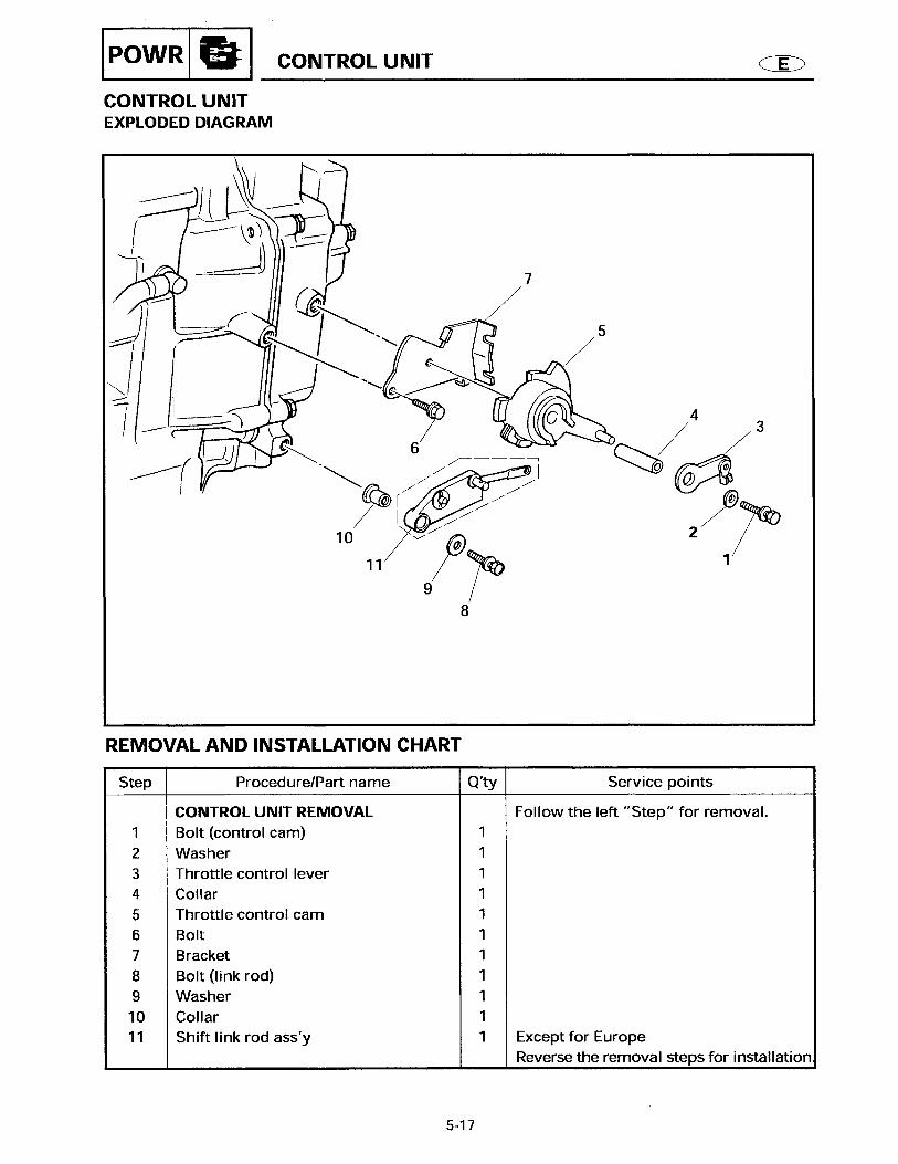
STEERING HANDLE ASSEMBLY (F15AEHP/F15PH)
33
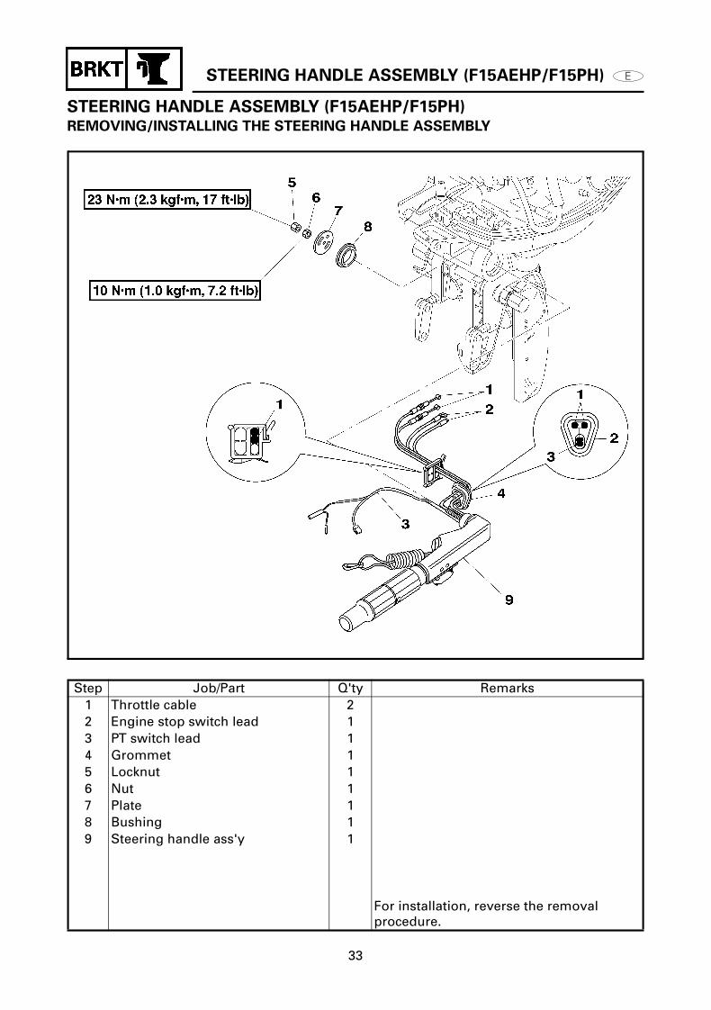
STEERING HANDLE ASSEMBLY (F15AEHP/F15PH)REMOVING/INSTALLING THE STEERING HANDLE ASSEMBLY
Step Job/Part Q'ty Remarks1 Throttle cable 22 Engine stop switch lead 13 PT switch lead 14 Grommet 15 Locknut 16 Nut 17 Plate 18 Bushing 19 Steering handle ass'y 1
For installation, reverse the removal procedure.

STEERING HANDLE ASSEMBLY (F15AEHP/F15PH)
34
DISASSEMBLING/ASSEMBLING THE STEERING HANDLE ASSEMBLY
Step Job/Part Q'ty Remarks1 Plate washer 12 Plate washer 13 Wave washer 24 Plate washer 15 Bushing 16 Screw 37 Clamp 18 Stay 19 Screw (with washer) 210 PT switch ass'y 111 Screw 112 Steering grip 113 Washer 1
Continued on next page.

STEERING HANDLE ASSEMBLY (F15AEHP/F15PH)
35
Step Job/Part Q'ty Remarks14 Spring 115 Bushing 116 Bolt 217 Stay 118 Split pin 119 Friction adjusting screw 120 Friction piece 121 Throttle cable 222 Throttle shaft 123 Engine stop switch 124 Steering handle bracket 1
For installation, reverse the removal procedure.

STEERING HANDLE ASSEMBLY (F15AEHP/F15PH)
36
INSTALLING THE PT SWITCH
1. Install: PT switch
NOTE:Tighten the PT switch mounting screw in sequence
BOTTOM COWLING ASSEMBLY
37
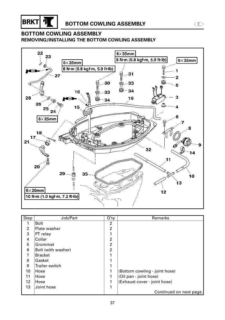
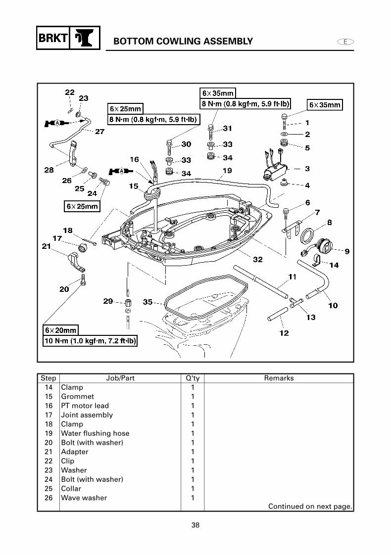
BOTTOM COWLING ASSEMBLYREMOVING/INSTALLING THE BOTTOM COWLING ASSEMBLY
Step Job/Part Q'ty Remarks1 Bolt 22 Plate washer 23 PT relay 14 Collar 25 Grommet 26 Bolt (with washer) 27 Bracket 18 Gasket 19 Trailer switch 110 Hose 1 (Bottom cowling - joint hose)11 Hose 1 (Oil pan - joint hose)12 Hose 1 (Exhaust cover - joint hose)13 Joint hose 1
Continued on next page.
BOTTOM COWLING ASSEMBLY
38
Step Job/Part Q'ty Remarks14 Clamp 115 Grommet 116 PT motor lead 117 Joint assembly 118 Clamp 119 Water flushing hose 120 Bolt (with washer) 121 Adapter 122 Clip 123 Washer 124 Bolt (with washer) 125 Collar 126 Wave washer 1
Continued on next page.

BOTTOM COWLING ASSEMBLY
39
Step Job/Part Q'ty Remarks27 Shift rod link 128 Gear shift handle 129 Shift rod nut 130 Bolt (with washer) 231 Bolt (with washer) 232 Bottom cowling assembly 133 Collar 434 Grommet 435 Rubber seal 1
For installation, reverse the removal procedure.
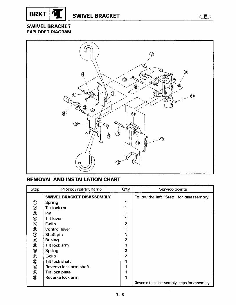
SWIVEL AND STEERING BRACKET
40
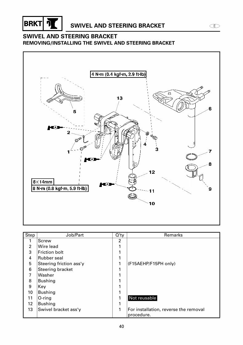
SWIVEL AND STEERING BRACKETREMOVING/INSTALLING THE SWIVEL AND STEERING BRACKET
Step Job/Part Q'ty Remarks1 Screw 22 Wire lead 13 Friction bolt 14 Rubber seal 15 Steering friction ass'y 1 (F15AEHP/F15PH only)6 Steering bracket 17 Washer 18 Bushing 19 Key 110 Bushing 111 O-ring 1 Not reusable12 Bushing 113 Swivel bracket ass'y 1 For installation, reverse the removal
procedure.

POWER TILT (PT) UNIT
41
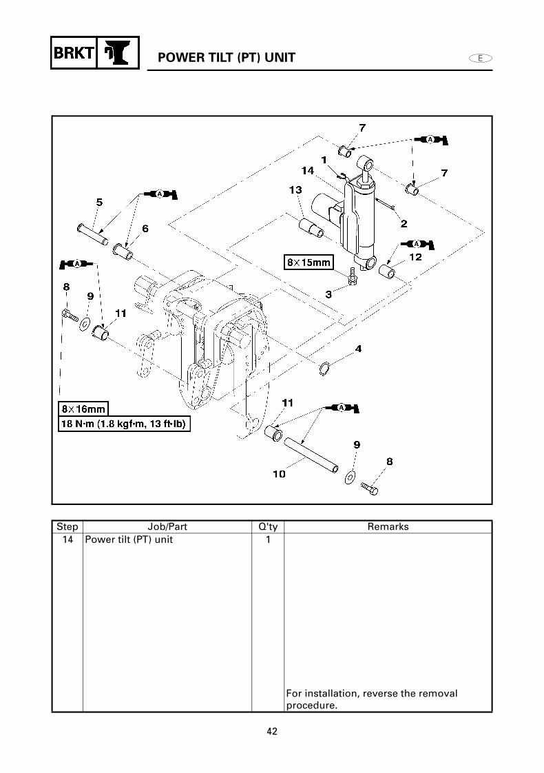
POWER TILT (PT) UNITREMOVING/INSTALLING THE POWER TILT (PT) UNIT
Step Job/Part Q'ty Remarks1 PT motor lead 12 Clamp 13 Bolt (with washer) 14 Circlip 15 Pin 16 Bushing 17 Bushing 28 Bolt 29 Washer 210 Pin 111 Bushing 212 Bushing 113 Collar 1
Continued on next page.
POWER TILT (PT) UNIT
42
Step Job/Part Q'ty Remarks14 Power tilt (PT) unit 1
For installation, reverse the removal procedure.

POWER TILT (PT) UNIT
43
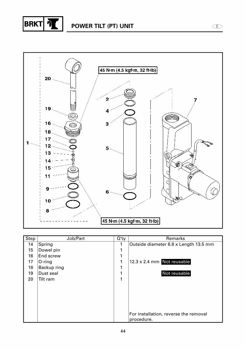
DISASSEMBLING/ASSEMBLING THE POWER TILT (PT) CYLINDER
Step Job/Part Q'ty Remarks1 Tilt ram assembly 12 Free piston 13 O-ring 1 20.8 x 2.4 mm Not reusable4 Backing ring 15 Cylinder case 16 O-ring 1 26.0 x 1.8 mm Not reusable7 Cylinder 18 O-ring 1 29.7 x 1.9 mm Not reusable9 O-ring 1 20.8 x 2.4 mm Not reusable10 Backup ring 111 Tilt piston 112 Ball 113 Pin 1
Continued on next page.
POWER TILT (PT) UNIT
44
Step Job/Part Q'ty Remarks14 Spring 1 Outside diameter 6.8 x Length 13.5 mm15 Dowel pin 116 End screw 117 O-ring 1 12.3 x 2.4 mm Not reusable18 Backup ring 119 Dust seal 1 Not reusable20 Tilt ram 1
For installation, reverse the removal procedure.

POWER TILT (PT) UNIT
45
DISASSEMBLING THE POWER TILT (PT)
CYLINDER
WARNING
To prevent the hydraulic fluid from
spurting out due to internal pressure, the
outboard should be kept fully tilted up
(the tilt rod at full length).
After removing the tilt motor or oil
reservoir, do not push the tilt rod down.
This may cause hydraulic fluid to spurt
out from the port.
CAUTION:
Do not wipe hydraulic system components
with rags, paper, tissues, or the like, as
fibers from such material will cause
malfunctions if they enter the system.
1. Loosen: End screw
2. Loosen: Tilt ram
NOTE:Hold the protruded portion a of the tilt piston with the aluminium plate 1 and turn to loose the tilt ram.
Power tilt wrench:
YB-06560 / 90890-06560
Power tilt wrench:
YB-06560 / 90890-06560

POWER TILT (PT) UNIT
46
ASSEMBLING THE POWER TILT (PT)
CYLINDER
1. Tighten: Tilt ram
NOTE:Hold the protruded portion a of the tilt piston with the aluminium plate 1 and tighten the tilt ram.
2. Fill: Fluid
Filling steps
(1) Fill the cylinder with the fluid to about 70 %.
NOTE:Put the fluid with the free piston 1 installed at the bottom of the cylinder.
(2) Install the tilt ram assembly.
NOTE:The tilt ram assembly is to be installed with the tilt piston 2 and end screw 3 in close contact.
3. Tighten: End screw
Power tilt wrench:
YB-06560 / 90890-06560
Tilt piston:
45 N•m (4.5 kgf•m, 32ft•lb)
Recommended PT fluid:
ATF Dexron II
Power tilt wrench:
YB-06560 / 90890-06560
End screw:
45 N•m (4.5 kgf•m, 32ft•lb)

POWER TILT (PT) UNIT
47
4. Bleed: Air
Bleeding step:
(1) Open the manual valve 1.
(2) Manually push in the tilt ram to its fully contracted state.
(3) Remove the reservoir cap 2 and supply the fluid to the prescribed level.
(4) Close the manual valve 1.
Reservoir cap:
5 N•m (0.5 kgf•m, 3.6ft•lb)

POWER TILT (PT) UNIT
48
(5) Connect the PT motor lead to the battery and place the tilt ram in it fully extended state.
NOTE: When the tilt ram is unstable or does not
move, supply the fluid to the prescribed level.
Repeat until the tilt ram is placed in its fully extended state.
Close the reservoir cap during operation.
(6) Alternately connect the PT motor leads to the battery and extend and contract the cylinder about 3 times.
NOTE: Operate the tilt ram to the full stroke and
relieve it for about 2 seconds at each stroke end.
Place the tilt ram finally in its fully extended state.
Tilt ram PT motor leadBattery
terminal
UpBlue (+)
Green (-)
Tilt ram PT motor leadBattery
terminal
UpBlue (+)
Green (-)
DownGreen (+)
Blue (-)

POWER TILT (PT) UNIT
49
(7) Open the manual valve, leave it to stand for about 1 second and close it.
NOTE:Check the fluid level and replenish if short.
(8) Leave it to stand for about 3 minutes and then repeat steps (6) and (7).
NOTE: Repeat for about 3 times until the up
relief sound is confirmed without delay when the cylinder extends.
Finally confirm the fluid level.
(9) Install the power tilt (PT) unit to the outboard motor.
NOTE:Carrying and working should be done with the power tilt (PT) unit erected.
(10) Operate the PT switch to move down the tilt, relieve it for about 1 second, and then immediately move up the tilt.
NOTE: For moving up the tilt, stop it at about
half the stroke. If it does not stop, air removal is not
complete. Take the steps (6) and (7) with it installed to the outboard motor.
Immediately after the tilt up, check that the outboard motor does not descend. Finally recheck the operation in this procedure.
(11) Move up the tilt and finally check the fluid level.
NOTE:If short, replenish.

POWER TILT (PT) UNIT
50
DISASSEMBLING/ASSEMBLING THE VALVES AND PUMP 1
Step Job/Part Q'ty Remarks1 Reservoir cap 12 O-ring 1 6.8 x 1.9 mm Not reusable3 Bolt 44 PT motor 15 O-ring 1 21.7 x 3.5 mm Not reusable6 O-ring 1 Not reusable7 Manual release rod 18 Pin 19 O-ring 1 5.8 x 1.9 mm Not reusable10 Sponge 111 Spring 2 Outside diameter 5.0 x Length 17.0 mm12 Manual release pin 213 Spring 2 Outside diameter 5.7 x Length 17.2 mm
Continued on next page.

POWER TILT (PT) UNIT
51
Step Job/Part Q'ty Remarks14 Absorver valve pin 215 Ball 216 Spring 2 Outside diameter 7.6 x Length 14.5 mm17 Spring 1 Outside diameter 8.8 x Length 18.1 mm18 Valve pin 219 Valve seal 2
For installation, reverse the removal procedure.
POWER TILT (PT) UNIT
52
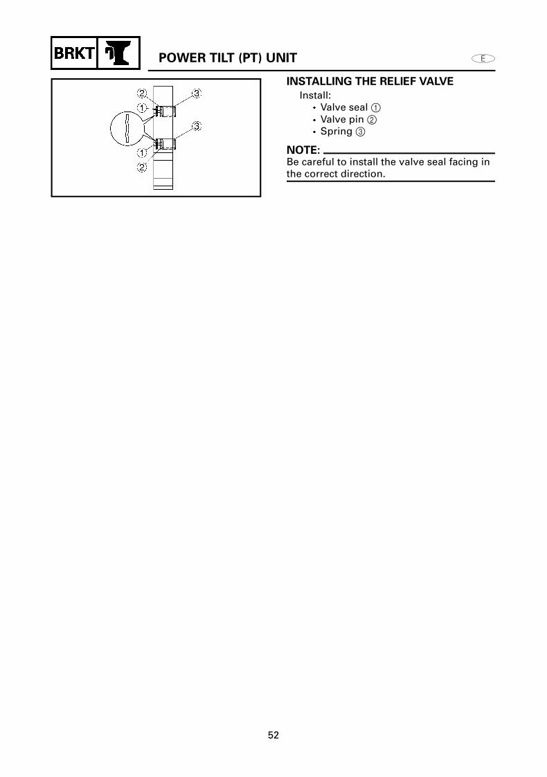
INSTALLING THE RELIEF VALVE
Install: Valve seal 1 Valve pin 2 Spring 3
NOTE:Be careful to install the valve seal facing in the correct direction.
POWER TILT (PT) UNIT
53
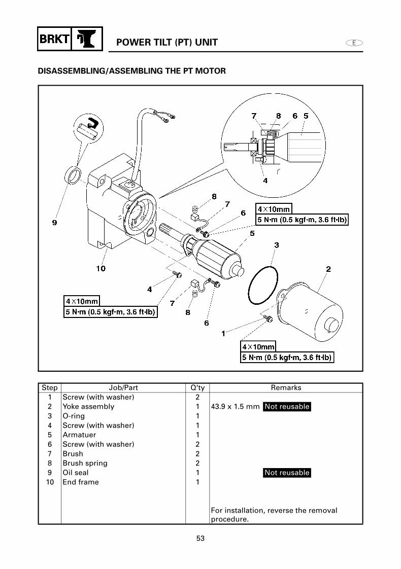
DISASSEMBLING/ASSEMBLING THE PT MOTOR
Step Job/Part Q'ty Remarks1 Screw (with washer) 22 Yoke assembly 1 43.9 x 1.5 mm Not reusable3 O-ring 14 Screw (with washer) 15 Armatuer 16 Screw (with washer) 27 Brush 28 Brush spring 29 Oil seal 1 Not reusable10 End frame 1
For installation, reverse the removal procedure.
POWER TILT (PT) UNIT
54
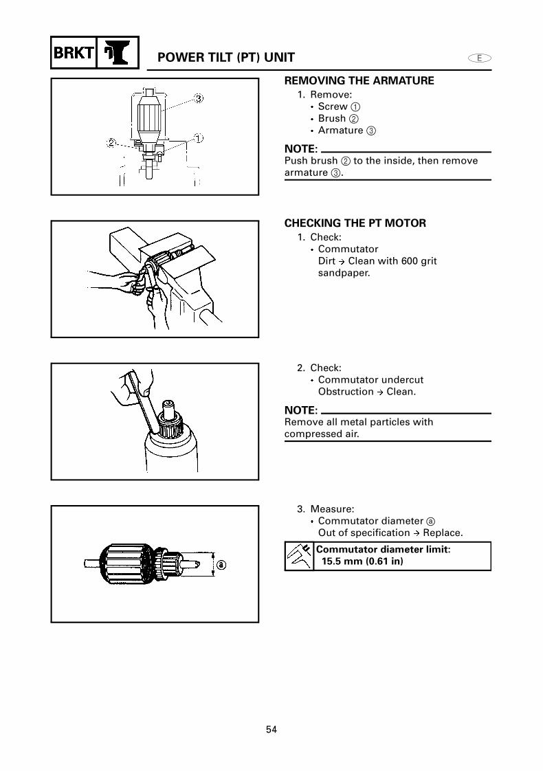
REMOVING THE ARMATURE
1. Remove: Screw 1 Brush 2 Armature 3
NOTE:Push brush 2 to the inside, then remove armature 3.
CHECKING THE PT MOTOR
1. Check: Commutator
Dirt Clean with 600 grit sandpaper.
2. Check: Commutator undercut
Obstruction Clean.
NOTE:Remove all metal particles with compressed air.
3. Measure: Commutator diameter a
Out of specification Replace.
Commutator diameter limit:
15.5 mm (0.61 in)

POWER TILT (PT) UNIT
55
4. Measure: Armature coil continuity
Out of specification Replace.
5. Measure: Brush length a
Out of specification Replace.
6. Check: End frame
Cracks/damage Replace.
7. Check: Yoke bushing
Cracks/damage Replace.
8. Check: Oil seal
Damage/wear Replace.
Armature coil continuity
Commutator segments Continuity
Segment - laminations No
continuity
Segment - shaft No
continuity
Brush length limit:
3 mm (0.12 in)

POWER TILT (PT) UNIT
56
CHECKING THE PT MOTOR ASSEMBLY
1. Check: PT motor operation
Incorrect operation Repair.
INSTALLING THE OIL SEAL
1. Install: Oil seal
PT motor operation
Blue (+), Green (-)Motor turns
clockwise
Green (+), Blue (-)Motor turns
counterclockwise
Oil seal attachment:
YB-06112/90890-06614
Driver rod:
YB-06071/90890-06652

POWER TILT (PT) UNIT
57
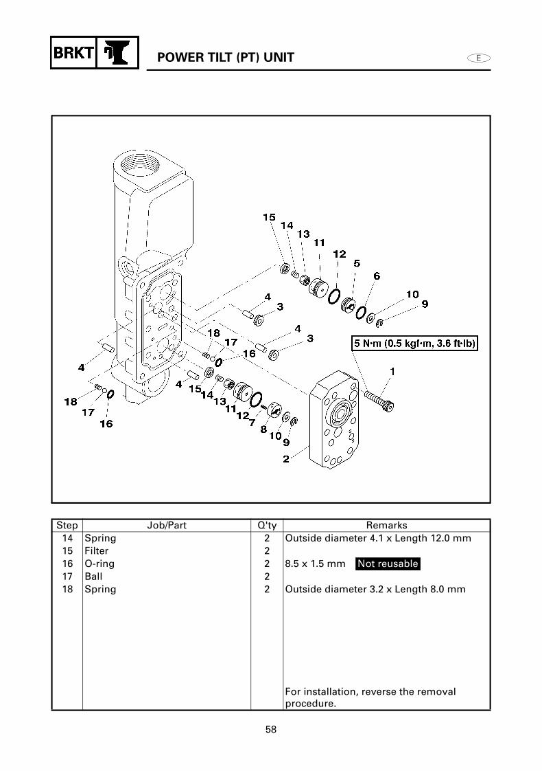
DISASSEMBLING/ASSEMBLING THE VALVES AND PUMP 2
Step Job/Part Q'ty Remarks1 Bolt 62 Gear housing 13 Gear 24 Dowel pin 45 Top chamber shuttle piston 16 O-ring 1 8.5 x 1.5 mm Not reusable7 Spring 2 Outside diameter 2.5 x Length 10.0 mm8 Bottom chamber shuttle piston 19 Circlip 210 Valve seal 211 Valve seat 212 O-ring 2 11.5 x 1.5 mm Not reusable13 Main valve 2
Continued on next page.
POWER TILT (PT) UNIT
58
Step Job/Part Q'ty Remarks14 Spring 2 Outside diameter 4.1 x Length 12.0 mm15 Filter 216 O-ring 2 8.5 x 1.5 mm Not reusable17 Ball 218 Spring 2 Outside diameter 3.2 x Length 8.0 mm
For installation, reverse the removal procedure.

CLAMP BRACKET
59
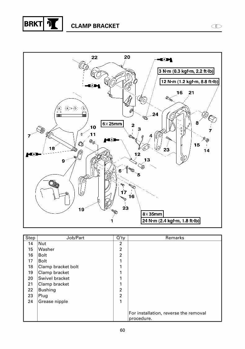
CLAMP BRACKETREMOVING/INSTALLING THE CLAMP BRACKET
Step Job/Part Q'ty Remarks1 Bolt (with washer) 12 Bolt 23 Wire lead 14 Anode 15 Screw 16 Wire lead 17 Cap nut 28 Clamp bracket cap 29 Clamp bracket plate 110 Spring pin 111 Stopper knob 112 Stopper shaft 113 Bushing 1
Continued on next page.
CLAMP BRACKET
60
Step Job/Part Q'ty Remarks14 Nut 215 Washer 216 Bolt 217 Bolt 118 Clamp bracket bolt 119 Clamp bracket 120 Swivel bracket 121 Clamp bracket 122 Bushing 223 Plug 224 Grease nipple 1
For installation, reverse the removal procedure.

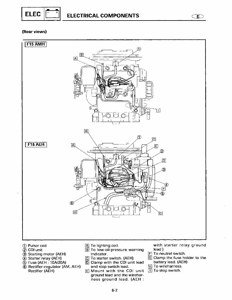
ELECTRICAL COMPONENTS
61
ELECTRICAL COMPONENTS
(Top view and port side view)
1 CDI unit2 Rectifier regulator3 Pulser coil4 PT terminal5 Lighting coil6 Charge coil7 Oil pressure switch8 Starter relay9 Starter motor0 PT relayA Ignition coilB Spark plugs
A Pass the lighting coil lead on the side of the flywheel cover, next to the boss as shown.
B Install the Pink lead onto the oil pressure switch. Cover the oil pressure switch after tightening it.
C Cover the oil pressure switch lead, ignition coil lead and charge coil lead with the corrugated plastic tube after connecting the same color leads.
D Install the connector in the proper direction as shown.
E Pass each high tension cord through the grommet.

ELECTRICAL COMPONENTS
62
(Front view) (F15AEP/F15PH)
1 Pulser coil2 CDI unit lead3 PT terminal4 Starter relay5 Starter motor6 Fuse7 Battery cable
A To the lighting coil.B To the emergency signal light.C To the starter switch.D Mount the starter relay ground
lead along with the CDI unit ground lead and the engine stop switch ground lead.
E CDI unit leads.F To the PT motor.G To the PT relay.H To the handle PT switch.I Clamp the fuse holder to the
battery cable.J To the neutral switch.
K To the rectifier regulatorL To the battery cable.M To the stop switch.N Mount the rectifier regulator
ground lead.
ELECTRICAL COMPONENTS
63
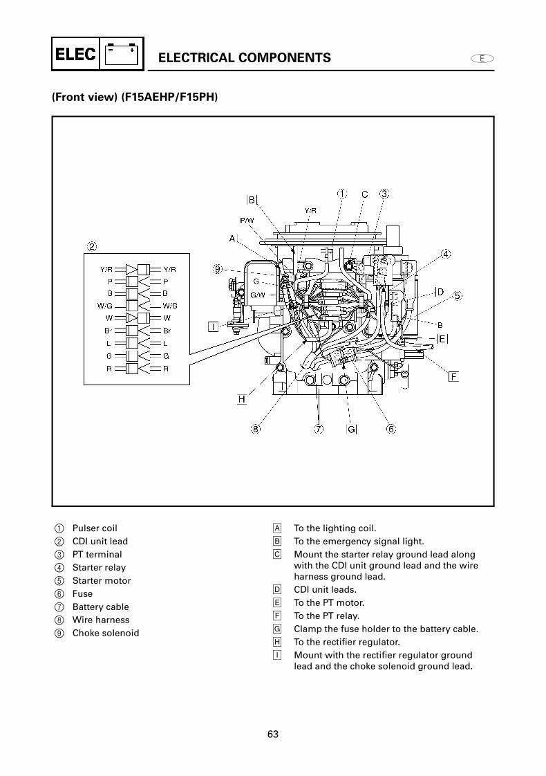
(Front view) (F15AEHP/F15PH)
1 Pulser coil2 CDI unit lead3 PT terminal4 Starter relay5 Starter motor6 Fuse7 Battery cable8 Wire harness9 Choke solenoid
A To the lighting coil.B To the emergency signal light.C Mount the starter relay ground lead along
with the CDI unit ground lead and the wire harness ground lead.
D CDI unit leads.E To the PT motor.F To the PT relay.G Clamp the fuse holder to the battery cable.H To the rectifier regulator.I Mount with the rectifier regulator ground
lead and the choke solenoid ground lead.
STARTER MOTOR
64
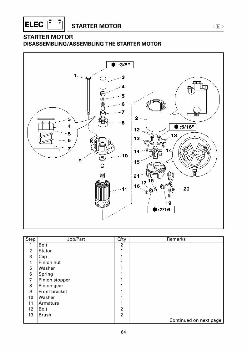
STARTER MOTOR
DISASSEMBLING/ASSEMBLING THE STARTER MOTOR
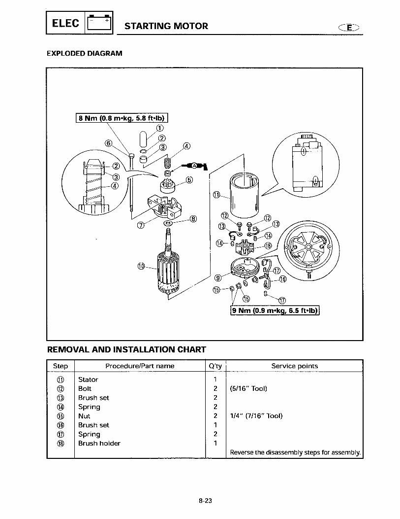
Step Job/Part Q'ty Remarks1 Bolt 22 Stator 13 Cap 14 Pinion nut 15 Washer 16 Spring 17 Pinion stopper 18 Pinion gear 19 Front bracket 110 Washer 111 Armature 112 Bolt 213 Brush 2
Continued on next page.

STARTER MOTOR
65
Step Job/Part Q'ty Remarks14 Spring 415 Brush holder 116 Nut 117 Nut 118 Washer 119 Rubber plate 120 Brush set 121 Rear bracket 1
For installation, reverse the removal procedure.

STARTER MOTOR
66
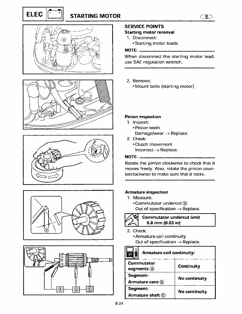
REMOVING THE PINION NUT
1. Remove: Pinion nut 1
NOTE:Secure the armature with the padded clamp, then remove the pinion nut.
CHECKING THE PINION GEAR
1. Check: Pinion gear teeth
Damage / wear Replace.
2. Check: Clutch movement Incorrect
Replace.
NOTE:Rotate the pinion gear clockwise to check that it moves freely. Also, rotate the pinion gear counterclockwise to make sure it locks.
CHECKING THE ARMATURE
1. Measure: Commutator undercut a
Out of specification Replace.
2. Check: Armature coil continuity
Out of specification Replace.
Commutator undercut limit:
0.8 mm (0.03 in)
Armature coil continuity:
Commutator segments a Continuity
Segment - Armature core b No continuity
Segment - Armature Shaft c No continuity
STARTER MOTOR
67
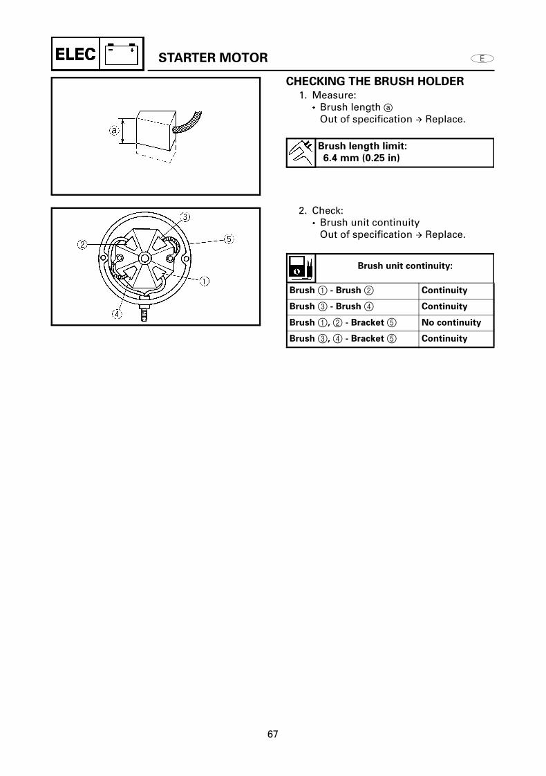
CHECKING THE BRUSH HOLDER
1. Measure: Brush length a
Out of specification Replace.
2. Check: Brush unit continuity
Out of specification Replace.
Brush length limit:
6.4 mm (0.25 in)
Brush unit continuity:
Brush 1 - Brush 2 Continuity
Brush 3 - Brush 4 Continuity
Brush 1, 2 - Bracket 5 No continuity
Brush 3, 4 - Bracket 5 Continuity

POWER TILT (PT) SYSTEM
68
POWER TILT (PT) SYSTEM
POWER TILT (PT) SYSTEM (F15AEP/F15PR)
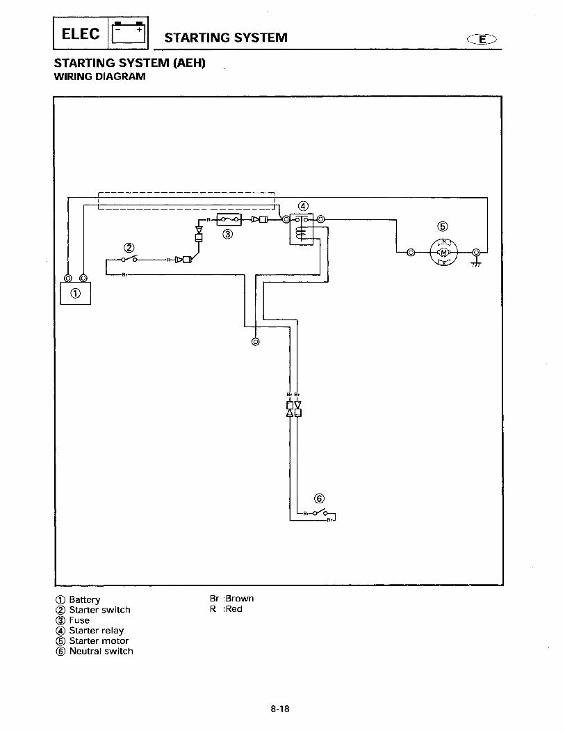
1 Battery2 Fuse3 Trailer switch4 PT relay5 Terminal6 PT motor
B : BlackG : GreenL : BlueLg : Light greenR : RedSb : Sky blue

POWER TILT (PT) SYSTEM
69
POWER TILT (PT) SYSTEM
POWER TILT (PT) SYSTEM (F15AEHP/F15PH)
1 Battery2 Terminal3 PT relay4 PT motor5 PT switch6 Trailer switch
A With trailer switch modelB To starter relayC To PT relayD Without trailer switch model
B : BlackG : GreenL : BlueLg : Light greenR : RedSb : Sky blue

POWER TILT (PT) SYSTEM
70
CHECKING THE PT SWITCH
Check: PT switch continuity
Out of specification Replace.
CHECKING THE TRAILER SWITCH
Check: Bottom cowling PT switch
continuity Out of specification Replace.
CHECKING THE PT RELAY
1. Check: PT relay continuity
Out of specification Replace.
A To battery
Leads color
Sky blue
(Sb)Red (R)
Light
green
(Lg)Switch
position
Up
Free
Down
Leads color
Sky blue
(Sb)Red (R)
Light
green
(Lg)Switch
position
Up
Free
Down
PT relay continuity
Sky blue (Sb) - Black (B)
Light green (Lg) - Black (B)
Continuity
Blue (L) - Black (B)
Green (G) - Black (B)
Continuity
Blue (L) - Red (R)
Green (G) - Red (R)
No continuity

POWER TILT (PT) SYSTEM
71
2. Check: PT relay operation
No continuity Replace.
Checking steps:
(1) Connect the digital tester between PT relay Blue (L) lead and Red (R) lead.
(2) Connect a 12-V battery as shown.
(3) Check that there is continuity between the PT relay terminals.
(4) Connect the tester between PT relay Green (G) lead and Red (R) lead.
(5) Connect a 12-V battery as shown.
(6) Check that there is continuity between the PT relay terminals.
Sky blue (Sb) lead Positive terminal
Black (B) lead Negative terminal
Light green (Lg) lead Positive terminal
Black (B) lead Negative terminal
TROUBLE ANALYSIS
72
TROUBLE ANALYSIS
TROUBLE ANALYSIS CHART
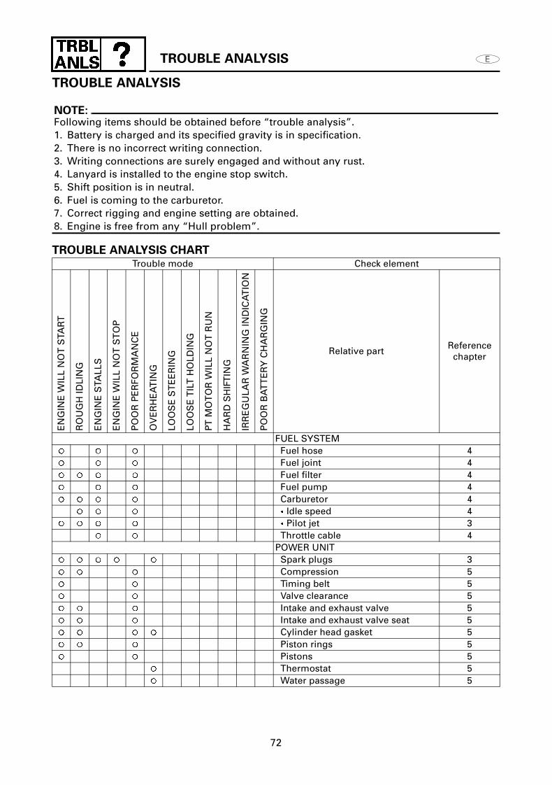
NOTE:Following items should be obtained before “trouble analysis”.1. Battery is charged and its specified gravity is in specification.2. There is no incorrect writing connection.3. Writing connections are surely engaged and without any rust.4. Lanyard is installed to the engine stop switch.5. Shift position is in neutral.6. Fuel is coming to the carburetor.7. Correct rigging and engine setting are obtained.8. Engine is free from any “Hull problem”.
Trouble mode Check element
EN
GIN
E W
ILL
NO
T S
TAR
T
RO
UG
H ID
LIN
G
EN
GIN
E S
TALL
S
EN
GIN
E W
ILL
NO
T S
TO
P
PO
OR
PE
RFO
RM
AN
CE
OV
ER
HE
AT
ING
LOO
SE
ST
EE
RIN
G
LOO
SE
TIL
T H
OLD
ING
PT M
OT
OR
WIL
L N
OT
RU
N
HA
RD
SH
IFT
ING
IRR
EG
ULA
R W
AR
NIN
G IN
DIC
AT
ION
PO
OR
BA
TT
ER
Y C
HA
RG
ING
Relative partReference
chapter
FUEL SYSTEM Fuel hose 4 Fuel joint 4 Fuel filter 4 Fuel pump 4 Carburetor 4
Idle speed 4 Pilot jet 3
Throttle cable 4POWER UNIT
Spark plugs 3 Compression 5 Timing belt 5 Valve clearance 5 Intake and exhaust valve 5 Intake and exhaust valve seat 5 Cylinder head gasket 5 Piston rings 5 Pistons 5
Thermostat 5 Water passage 5

TROUBLE ANALYSIS
73
Trouble mode Check element
EN
GIN
E W
ILL
NO
T S
TAR
T
RO
UG
H ID
LIN
G
EN
GIN
E S
TALL
S
EN
GIN
E W
ILL
NO
T S
TO
P
PO
OR
PE
RFO
RM
AN
CE
OV
ER
HE
AT
ING
LOO
SE
ST
EE
RIN
G
LOO
SE
TIL
T H
OLD
ING
PT M
OT
OR
WIL
L N
OT
RU
N
HA
RD
SH
IFT
ING
IRR
EG
ULA
R W
AR
NIN
G IN
DIC
AT
ION
PO
OR
BA
TT
ER
Y C
HA
RG
ING
Relative partReference
chapter
LOWER UNIT Neutral position 6 Clutch 6 Gears 6
Water inlet 6 Water pump 6 Propeller shaft and propeller 6
Shifter/Pin 6 Shift cam 6 Shift rod or Shift cable 6 Lower case 6
Shim adjustment 6BRACKET UNIT
Bracket 7 Mount rubber 7 Steering friction ass’y 7
PT UNIT Fluid level 7 Manual valve 7 Fluid passage 7
PT motor 7ELECTRICAL
Ignition coil 8 Ignition control system 8 Starting system 8 Charging system 8
PT control system 8


Printed on recycled paper
Printed in USAApr. 2000 - x 1 (F15AEP, F15AEHP)
YAMAHA MOTOR CO., LTD.

Sb Lg
R
LgSb
G
Br
B
R
W
Sb
L
Lg W
Br
B
L
R
G
Sb
Lg
BB
W B O P L B B
W B
Br W/GP/WY/R
W/GP/WY/R
Br
Br
L
L
R
R
G
G
L
L
P
P
O
O
B
B
B
BB
Br
Br
R
R Sb Lg
Sb R LgUP
FREEDOWN
B
G/W
G
RR R B
B
R
B
W/G
G/W
G
R R
RB
+-
L
G
LL
G G
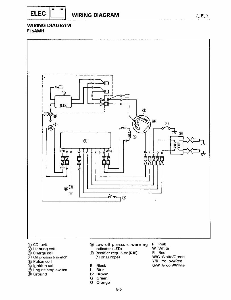
Pulsercoil
11
CDI unit1
Battery2
Emergencysignal light
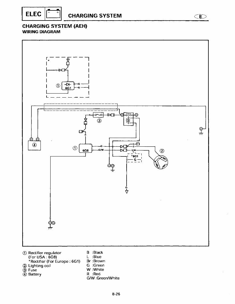
3 Rectifier/regulator
4
Fuse(20A)5Starter relay6
Starting motor7
Oil pressureswitch
10
Ignition coil12
Terminal ass'y13
Charge coil9
BlackBrownGreenBlueLight greenOrangePinkRedSky blueWhite
B:Br:G:L:Lg O: P: R:Sb: W:
P/W:W/G:Y/R:G/W:
Pink/whiteWhite/greenYellow/redGreen/whiteLighting coil8
PT motor14
PT relay15
Sparkplugs
16
Trailer switch17
Fuel enrichsolenoid
18
Lg Lg
Sb
Lg
Sb
Lg
Sb
B
R
B L R G
Sb Lg
LB G R
Y/R
P/W
WIRING DIAGRAM F15AEP/F15PR

Sb Lg
R
LgSb
RB
+-
Br
R
R
R
R B
B
B
R
R
R
LL
G G
R Sb Lg
Sb R LgUP
FREEDOWN
B
G G
B B
G
BW
L
L
P
P
O
O
B
B
Br
Br
W B O P L B B
W B
Br Br
Br
Br
Br
Br
W/G
B
Br
B
Sb
Lg
Sb
Lg
Sb LgR RSb Lg
A
C
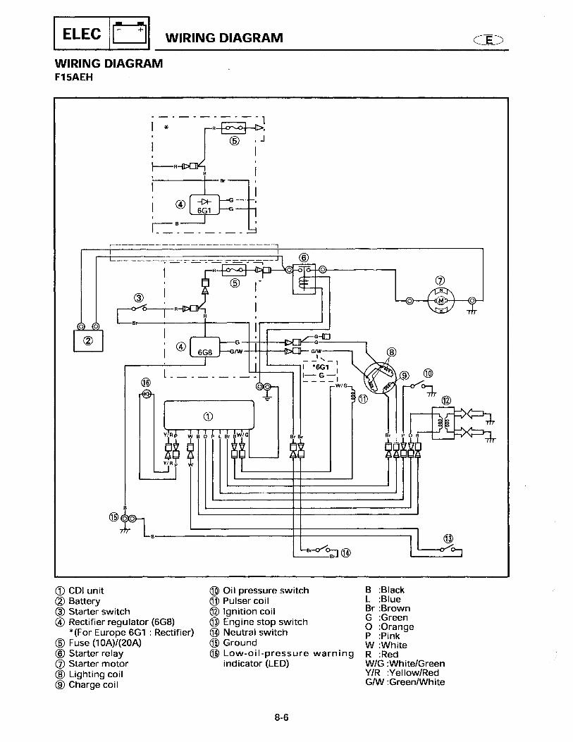
Pulser coil11
CDI unit1
Battery2
Starter switch3
Rectifier/regulator
4
Fuse(20A)5
Starter relay6
Starting motor7
Oil pressureswitch
10
Ignition coil12
Terminal ass'y13
Charge coil9
BlackBrownGreenBlueLight greenOrangePinkRedSky blueWhite
B:Br:G:L:Lg O: P: R:Sb: W:
P/W:W/G:Y/R:G/W:
Pink/whiteWhite/greenYellow/redGreen/white
Lighting coil8
PT motor14
PTrelay
15
Sparkplugs
16
PT switch17
Engine stop switch18
With trailer switch model
B To starter relay
Neutral switch19
Emargencysignal light
20
To PT relay
Trailer switch
21
Lg
Sb
Lg
Sb Lg
SbLg
Lg
Sb
Lg
L
G
PT switch17
G/W G/W
W/G
W/G
P/WY/R
P/WY/R
D Without trailer switch model
R
B
Sb Lg
LB G R
Y/RP/W
WIRING DIAGRAM F15AEHP/F15PH