15 march 2004cal poly meeting status of midwest 13 effort status of braidwood site general strategy...
TRANSCRIPT

15 March 2004 Cal Poly Meeting
Status of Midwest 13 Effort
• Status of Braidwood site
• General strategy and layout of experiment
• Civil construction estimate
• Plans
Ed Blucher
(A vertical shaft access experiment)

Midwest Collaboration
ANL: Maury Goodman, David Reyna
Chicago: Erin Abouzaid, Kelby Anderson, Ed Blucher, Jim Pilcher, Matt Worcester
Columbia: Janet Conrad, Jon Link, Mike Shaevitz
FNAL: Larry Bartoszek, Dave Finley, Hans Jostlein, Chris Laughton, Ray Stefanski
Kansas: Tim Bolton, Noel Stanton
Oxford: Steve Biller, Nick Jelley
Pittsburgh: Donna Naples, Vittorio Paolone
Texas: Josh Klein

We considered several sites in Illinois and Kansas. We have focused on the Braidwood site managed by Exelon.
Exelon has been very cooperative, providing extensive geological information, detailed site drawings, etc. No objection to detector just outside controlled perimeter.
Exelon:
“We are excited about the possibility of participating in a scientific endeavor of this nature”
“At this time we see no insurmountable problems that would preclude going forward with this project…”

Braidwood site

Braidwood site
Features of Braidwood site:
• 23.6 GW reactors – 7.17 GW maximum power• Flat: flexibility, equal overburden at near and far sites, surface transportation of detectors• Favorable geology (dolomitic limestone): good for excavation, low radioactivity (order of magnitude lower U, Th than granite)

Detector Concept
~200 m ~1600 m
Sensitivity goal: sin22~0.01
General Strategy of Experiment
• 1 near detector and 2 far detectors• 6.5 m diameter spherical detectors with 3 zones (Gd-loaded scint.) • 25-50 ton fid. mass per detector, depending on required buffer regions.• Movable detectors with surface transport for cross-calibration• Near and far detectors at same depth of 450 mwe (contingent on bore holes)• Near detector at ~200 m security perimeter (L~270 m)• Far detector at ~1800 m• Full detector construction above ground

3-zone Gd-based Detector
I
IIIII
I. Gd-loaded liquid scintillatorII. catcher: liquid scintillator (no Gd)III. Non-scintillating buffer
I. R=1.9 m, m=25 tonsII. R=2.4 mIII. R=3.25 m
6.5 m
I. R=2.4 m, m=50 tonsII. R=2.7 mIII. R=3.25 m
Total detector mass ~150 tons
PMTsTwo examples:

750-ton capacity Crawler Crane
Test lift of 750 tons

Braidwood Site
Reactors
Controlled perimeter

Layout for underground construction estimate
Far shaftNear shaft
Near detect. hall
Reactors
Braidwood

Basis of Underground Construction Estimate
Reactors
300 m
1600 m
1800 m
TWO SHAFT LAYOUT (Forms Basis of Estimate) (Schematic scope representation - shaft and tunnel layouts will be adjusted to match site constraints)
10 m Ø Shaft
12 m Span Detector Rooms
8 m Span Running Tunnel on 1% Gradient
4 m Span Safety Refuge 1 m Ø Ventilation Shaft (Separate Air Supply) 12 m Span
Detector Room 32 m long
1% Gradient to Shaft for gravity drainage
Reactors
Safety Refuge
NOT TO SCALE
120m to Tunnel Crown

Near & Far Shaft Layouts
Not to Scale
10 m
6.5 m
0.75m Duct
0.75m Duct
2 Alimak SE Elevators
~ 90 x 120 cmAssembled Detector
Cable Rack
Cable Rack
Water Pipelines
6.5m
8m
30cm
8.5m
Flexible Cables (wall mounted)
Rigid Pipes (floor mounted)
Detector Section
Assume Diablo Canyon Loads
Tunnel cross section
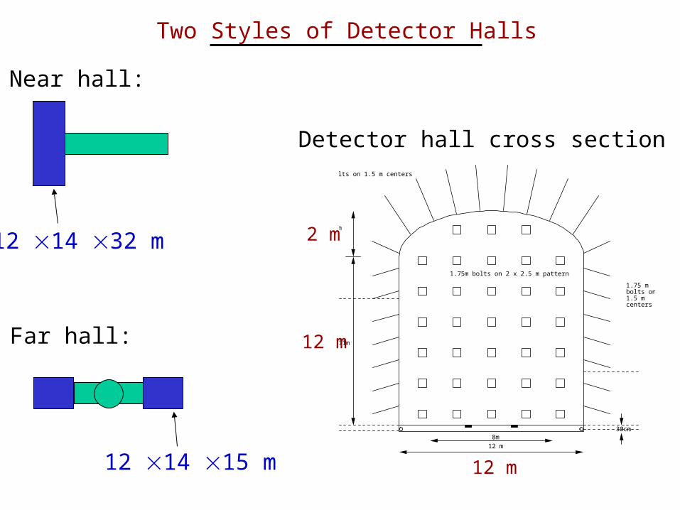
Two Styles of Detector Halls
Near hall:
8.5m
8m30cm
3 m
11m
3 m bolts on 1.5 m centers
1.75 m bolts on 1.5 m centers
1.75m bolts on 2 x 2.5 m pattern
12 m
Far hall:
12 14 15 m
12 14 32 m
12 m
12 m
2 m
Detector hall cross section

Layout used for underground construction estimate:300 mwe, two shafts, different detector hall designs, 300m tunnel ~ $35 million, 39 months (sequential shaft construction)
Revised layout:•Increase depth to 450 mwe (160 m rock + 20 m soil) contingent on bore hole results Additional cost: $5 million + 6 months (3 months per shaft)
•Site near detector shaft to shorten or eliminate tunnel stubPotential savings: $9 million and 9 months
•Use near hall design at both near and far sitesSavings: $1 million
Cost of revised layout: ~$30 million ($25-35 million)Construction time: ~36 months with sequential construction of near and far sites; reduced time with simultaneous construction

Revised Layout
Far shaft
Reactors
Braidwood
Site near shaftto shorten oreliminate tunnel
Plans
• Settle location of shafts (in consultation with Exelon)• Bore holes to full depth at both shaft positions: info
about geology, radioactivity, density; will reduce required contingency for construction
• Complete surface layout: (e.g.,surface building(s), infrastructure for detector movement)
• Optimize detector design (buffer regions, calibration system, active and passive shielding, etc.)