150a, 150f, l150f, d150h, 175d, 200f, l200f, 200g, 225d
TRANSCRIPT

64C-28197-Z8-11
SERVICEMANUAL
150A, 150F,L150F, D150H,
175D, 200F,L200F, 200G,
225D

E
PREFACE
This manual has been prepared by the Yamaha Motor Company, Ltd. primarily for use byYamaha dealers and their trained mechanics when performing maintenance procedures andrepairs to Yamaha equipment. It has been written to suit the needs of persons who have abasic understanding of the mechanical and electrical concepts and procedures inherent in thework, for without such knowledge attempted repairs or service to the equipment could renderit unsafe or unfit for use.
Because the Yamaha Motor Company, Ltd. has a policy of continuously improving its prod-ucts, models may differ in detail from the descriptions and illustrations given in this publica-tion. Use only the latest edition of this manual. Authorized Yamaha dealers are notifiedperiodically of modifications and significant changes in specifications and procedures, andthese are incorporated in successive editions of this manual.
150A, 150F, L150F, D150H, 175D,
200F, L200F, 200G, 225D
SERVICE MANUAL
1998 Yamaha Motor Co., Ltd.
1st Edition, October 1998
All rights reserved.
No part of this publication may be
reproduced or transmitted in any form or
by any means including photocopying and
recording without the written permission of
the copyright holder.
Such written permission must also be
obtained before any part of this publication
is stored in a retrieval system of any nature.

E
HOW TO USE THIS MANUAL
MANUAL FORMAT
All of the procedures in this manual are organized in a sequential, step-by-step format. Theinformation has been compiled to provide the mechanic with an easy to read, handy refer-ence that contains comprehensive explanations of all disassembly, repair, assembly, andinspection operations.For instance, the condition of a faulty component will precede an arrow symbol and the course of action required will follow the symbol.
• BearingsPitting/scratches
→
Replace.To assist you in finding your way through this manual, the section title and major heading isgiven at the top of every page.
MODEL INDICATION
Multiple models are mentioned in this manual and their model indications are noted as fol-lows.
ILLUSTRATIONS
The illustrations within this service manual represent all of the designated models.
CROSS REFERENCES
The cross references have been kept to a minimum. Cross references will direct you to theappropriate section or chapter.
Model name 150AET L150AET 150FETO L150FETO 150GETO
USA and Canada name
C150TR — — S150TR — L150TR P150TR
Indication 150AET L150AET 150FETO S150FETO L150FETO LS150FETO 150GETO
Model name D150HETO 175AET 175DETO 175FETO 200AET L200AET
USA and Canada name
D150TR — — S175TR P175TR — —
Indication D150HETO 175AET 175DETO S175DETO 175FETO 200AET L200AET
Model name 200FETO L200FETO 200GETO 225DET 225DETO
USA and Canada name
200TR S200TR — L200TR P200TR — —
Indication 200FETO S200FETO L200FETO LS200FETO 200GETO 225DET 225DETO

E
IMPORTANT INFORMATION
In this Service Manual particularly important information is distinguished in the followingways.
The Safety Alert Symbol means ATTENTION! BECOME ALERT! YOUR SAFETY ISINVOLVED!
WARNING
Failure to follow WARNING instructions could result in severe injury or death to the machine
operator, a bystander, or a person inspecting or repairing the outboard motor.
CAUTION:
A CAUTION indicates special precautions that must be taken to avoid damage to the out-
board motor.
NOTE:
A NOTE provides key information to make procedures easier or clearer.
SPECIFICATIONS
These are given in bold type at each procedure. It is not necessary to leave the section deal-ing with the procedure in order to look up the specifications.It is important to note the differences in specifications of models. When a procedure relates tomore than one model, the main differences in specifications will be shown in a table similarto the following.
Model name 150AET L150AET 150FETO L150FETO 150GETO
USA and Canada name
C150TR — — S150TR — L150TR P150TR
Lubrication system Pre-mixed Pre-mixed Oil injection Oil injection Oil injection
Model name D150HETO 175AET 175DETO 175FETO 200AET L200AET
USA and Canada name
D150TR — — S175TR P175TR — —
Lubrication system Oil injection Pre-mixed Oil injection Oil injection Pre-mixed Pre-mixed
Model name 200FETO L200FETO 200GETO 225DET 225DETO
USA and Canada name
200TR S200TR — L200TR P200TR — —
Lubrication system Oil injection Oil injection Oil injection Pre-mixed Oil injection

E
HOW TO USE THIS MANUAL
1
The main points regarding removing/installing and disassembling/assembling proceduresare shown in the exploded views.
2
The numbers in the exploded views indicate the required sequence of the procedure andshould be observed accordingly.
3
Symbols are used in the exploded views to indicate important aspects of the procedure. A list of meanings for these symbols is provided on the following page.
4
It is important to refer to the job instruction charts at the same time as the exploded views.These charts list the sequence that the procedures should be carried out in, as well as pro-viding explanations on part names, quantities, dimensions and important points relatingto each relevant task.
Example:O-ring size 39.5
×
2.5 mm: inside diameter (D)
×
ring diameter (d)
5
In addition to tightening torques, the dimensions of the bolts and screws are also men-tioned.
Example:Bolt and screw size : bolt and screw diameter (D)
×
length (L)
6
In addition to the exploded views and job instruction charts, this manual provides individ-ual illustrations when further explanations are required to explain the relevant procedure.
d
D
10 × 25 mm
D
L

E
SYMBOLS
Symbols
1
to
9
are designed as thumb-tabs to indicate the content of a chapter.
1
General information
2
Specifications
3
Periodic inspections and adjustments
4
Fuel system
5
Power unit
6
Lower unit
7
Bracket unit
8
Electrical systems
9
Trouble analysis
Symbols
0
to
E
indicate specific data.
0
Special tool
A
Specified liquid
B
Specified engine speed
C
Specified torque
D
Specified measurement
E
Specified electrical value[Resistance (
Ω
), Voltage (V), Electric current(A)]
Symbol
F
to
H
in an exploded diagramindicate the grade of lubricant and the loca-tion of the lubrication point.
F
Apply Yamaha 2-stroke outboard motor oil(TC-W3)
G
Apply water resistant grease (Yamaha grease A, Yamaha marine grease)
H
Apply molybdenum disulfide oil
Symbols
I
to
N in an exploded diagramindicate the grade of the sealing or lockingagent and the location of the applicationpoint.
I Apply Gasket Maker
J Apply Yamabond #4 (Yamaha bond number 4)
K Apply LOCTITE No. 271 (Red LOCTITE)L Apply LOCTITE No. 242 (Blue LOCTITE)M Apply LOCTITE No. 572N Apply silicon sealant
1 2
3 4
5 6
7 8
9 0
A B
C D
E F
G H
I J
K L
M N
GENINFO SPEC
INSPADJ
FUEL
POWR LOWR
BRKT– +
ELEC
TRBLANLS
T R..
E
A M
GM 4
271
LT
242
LT
572
LT LTSS

E
CONTENTS
GENERAL INFORMATION
1
SPECIFICATIONS
2
SPEC
PERIODIC INSPECTIONS AND ADJUSTMENTS
3
FUEL SYSTEM
4
FUEL
POWER UNIT
5
POWR
LOWER UNIT
6
LOWR
BRACKET UNIT
7
BRKT
ELECTRICAL SYSTEMS
8
ELEC
TROUBLE ANALYSIS
9
GEN INFO
INSP ADJ
– +
TRBL ANLS


E
1 2 3 4 5 6 7 8 9
GENINFO
CHAPTER 1
GENERAL INFORMATION
IDENTIFICATION
............................................................................................ 1-1SERIAL NUMBER..................................................................................... 1-1STARTING SERIAL NUMBERS ............................................................... 1-1
SAFETY WHILE WORKING
............................................................................ 1-2FIRE PREVENTION................................................................................... 1-2VENTILATION........................................................................................... 1-2SELF-PROTECTION.................................................................................. 1-2OILS, GREASES AND SEALING FLUIDS................................................ 1-2GOOD WORKING PRACTICES................................................................ 1-3DISASSEMBLY AND ASSEMBLY........................................................... 1-4
SPECIAL TOOLS
............................................................................................. 1-5MEASURING ............................................................................................ 1-5REMOVING AND INSTALLING ............................................................... 1-7

1-1
GENINFO
E
IDENTIFICATION
IDENTIFICATION 1
SERIAL NUMBER
The outboard motor’s serial number isstamped on a label which is attached to theport clamp bracket.
NOTE:
As an antitheft measure, a special label onwhich the outboard motor’s serial numberis stamped is bonded to the port clampbracket. The label is specially treated sothat peeling it off causes cracks across the
serial number.
1
Model name
2
Approval model code
3
Transom height
4
Serial number
S67H1010
1020
STARTING SERIAL NUMBERS
The starting serial number blocks are as fol-lows:
Model name Approval
model
code
Starting serial
number
Model name Approval
model
code
Starting serial
numberWorld-
wideUSA Canada
World-
wideUSA Canada
150AET C150TR — 6G4L: 305521 - 175FETO P175TR 62H L: 500647 -
X: 704396 -200AET — 6G6
L: 308781 -
L150AET — 6K0 X: 750347 - X: 707018 -
150FETO—
6G4L: 352137 - L200AET — 6K1 X: 752202 -
S150TR X: 504118 -200FETO
200TR —6G6
L: 350991 -
L150FETO—
6K0L: 350142 - S200TR X: 506004 -
L150TR — X: 501152 -L200FETO
—6K1
L: 350141 -
150GETO P150TR6J9
L: 502379 - L200TR — X: 501625 -
D150HETO D150TR — L: 601301 - 200GETO P200TR 61H L: 502516 -
175AET —
6G5
L: 302440 -225DET —
6K7
L: 400393 -
X: 701017 - X: 500160 -
175DETO— L: 350273 -
225DETO —L: 450255 -
S175TR — X: 501252 - X: 550266 -

1-2
GENINFO
E
SAFETY WHILE WORKING
SAFETY WHILE WORKING 1
The procedures given in this manual arethose recommended by Yamaha to be fol-lowed by Yamaha dealers and theirmechanics.
FIRE PREVENTION
Gasoline (petrol) is highly flammable.Petroleum vapor is explosive if ignited.Do not smoke while handling gasoline andkeep it away from heat, sparks and openflames.
1030
VENTILATION
Petroleum vapor is heavier than air and isdeadly if inhaled in large quantities. Engineexhaust gases are harmful to breathe. When test-running an engine indoors,maintain good ventilation.
1040
SELF-PROTECTION
Protect your eyes with suitable safetyglasses or safety goggles, when grinding orwhen doing any operation which maycause particles to fly off. Protect hands andfeet by wearing safety gloves or protectiveshoes if appropriate to the work you aredoing.
1050
OILS, GREASES AND SEALING
FLUIDS
Use only genuine Yamaha oils, greases andsealing fluids or those recommended byYamaha.
1060

1-3
GENINFO
E
SAFETY WHILE WORKING
Under normal conditions of use, thereshould be no hazards from the use of thelubricants mentioned in this manual, butsafety is all-important, and by adoptinggood safety practices, any risk is minimized.A summary of the most important precau-tions is as follows:
1. While working, maintain good stan-dards of personal and industrialhygiene.
2. Clothing which has become contami-nated with lubricants should bechanged as soon as practicable, andlaundered before further use.
3. Avoid skin contact with lubricants; donot, for example, place a soiled wiping-rag in your pocket.
4. Hands and any other part of the bodywhich have been in contact with lubri-cants or lubricant-contaminated cloth-ing, should be thoroughly washed withhot water and soap as soon as practica-ble.
5. To protect the skin, the application of asuitable barrier cream to the handsbefore working, is recommended.
6. A supply of clean lint-free cloths shouldbe available for wiping purposes.
GOOD WORKING PRACTICES
1. The right toolsUse the recommended special tools toprotect parts from damage. Use theright tool in the right manner – do notimprovise.
2. Tightening torqueFollow the tightening torque instruc-tions. When tightening bolts, nuts andscrews, tighten the large sizes first, andtighten inner-positioned fixings beforeouter-positioned ones.
1070

1-4
GENINFO
E
SAFETY WHILE WORKING
3. Non-reusable itemsAlways use new gaskets, packings, O-rings, split-pins, circlips, etc., on reas-sembly.
1080
DISASSEMBLY AND ASSEMBLY
1. Clean parts with compressed air whendisassembling.
2. Oil the contact surfaces of moving partsbefore assembly.
1090
3. After assembly, check that moving partsoperate normally.
1100
4. Install bearings with the manufacturer’smarkings on the side exposed to view,and liberally oil the bearings.
5. When installing oil seals, apply a lightcoating of water-resistant grease to theoutside diameter.

1-5
GENINFO
E
SPECIAL TOOLS
SPECIAL TOOLS 1
Using the correct special tools recom-mended by Yamaha, will aid the work andenable accurate assembly and tune-up.Improvising and using improper tools candamage the equipment.
NOTE:
• For U.S.A. and Canada, use part numbersthat start with “J-”, “YB-”, “YM-”, “YU-”or “YW-”.
• For others countries, use part numbers
that start with “90890-”.
MEASURING
1
TachometerP/N. YU-08036-A ............................
a
90890-06760 ...........................
b
2
Pressure testerP/N. YB-35956
90890-06762
3
Mity vacP/N. YB-35956
90890-06756
4
Pinion height gaugeP/N. YB-34432-7, YB-34432-11,
YB-34432-97 90890-06702
5
Dial gauge setP/N. YU-03097
90890-01252
6
Magnetic baseP/N. YU-34481
90890-06705
7
Digital caliperP/N. 90890-06704
8
Backlash indicatorP/N. YB-06265
90890-06706
9
Magnetic base attaching plateP/N. YB-07003
90890-07003
0
Hydraulic pressure gaugeP/N. 90890-06776
A
Up-relief valve attachmentP/N. 90890-06773Down-relief valve attachmentP/N. 90890-06774
1b
2 3
4 5
6 7
8 9
0 A
a

1-6
GENINFO
E
SPECIAL TOOLS
B
Digital testerP/N. J-39299
90890-06752
C
Peak voltage adapterP/N. YU-39991 ................................
a
90890-03169 ...........................
b
D
Spark gap testerP/N. YM-34487 ...............................
a
90890-06754 ...........................
b
E
Diagnostic indicatorP/N. YB-06765
90890-06765
F
Shimming gaugeP/N. YB-34446-1, YB-34446-3,
YB-34446-4, YB-34446-7, YB-34446-8
G
Shimming gaugeP/N. YB-34468-1, YB-34468-2,
YB-34468-6
H
Shimming plateP/N. 90890-06701
I
Shift rod wrenchP/N. YB-06052
90890-06052J Test harness
P/N. YB-06770, YB-38831, YB-3883290890-06770, 90890-06771, 90890-06772
Cb
B
a
Dba
E F
I J
G H

1-7
GENINFO ESPECIAL TOOLS
REMOVING AND INSTALLING
1 Flywheel magnet assembly holderP/N. YB-06139 ................................ a
90890-06522 ........................... b 2 Universal puller
P/N. YB-06117 ................................ a 90890-06521 ........................... b
3 Bearing/oil seal attachmentP/N. YB-06196 ................................ a
90890-06610, 90890-06637 .... b 4 Driver rod
P/N. YB-0607190890-06602, 90890-06604, 90890-06605, 90890-06606, 90890-06652
5 Bearing/oil seal attachmentP/N. YB-06205
90890-066636 Bearing/oil seal attachment
P/N. YB-06194, YB-06195, YB-06200, YB-06246, YB-06258, YB-06276, YB-0633690890-06619, 90890-06622, 90890-06623, 90890-06624, 90890-06629
7 Piston ring compressorP/N. YU-33294 ................................ a
90890-06530 ........................... b 8 Bearing separator
P/N. YB-06219 ................................ a 90890-06534 ........................... b
9 Guide plate standP/N. 90890-06538
0 Guide plateP/N. 90890-06501
1ba
3
ba
4 5
6
9 0
7ba
8ba
2ba

1-8
GENINFO ESPECIAL TOOLS
A Bearing pullerP/N. 90890-06535
B Bearing/oil seal attachmentP/N. 90890-06659, 90890-06660,
90890-06661, 90890-06662C Ring nut wrench
P/N. YB-3444790890-06512
D Ring nut wrench extensionP/N. YB-06513
90890-06513E Propeller shaft housing puller
P/N. YB-06207 ................................ a YB-06502 ................................ b90890-06502
F Center boltP/N. 90890-06504
G Slide hammerP/N. YB-06096
90890-06531H Small universal claws
P/N. 90890-06536I Bearing/oil seal depth plate
P/N. YB-06213, YB-34474 .............. a 90890-06603 ........................... b
J Drive shaft holderP/N. YB-06201
90890-06520K Pinion nut holder
P/N. 90890-06505L Pinion nut holder attachment
P/N. 90890-06508M Bearing/oil seal attachment
P/N. 90890-06609, 90890-06612, 90890-06631, 90890-06633, 90890-06636, 90890-06653
N Bearing pullerP/N. YB-06029, YB-06247
90890-06523O Large universal claws
P/N. 90890-06532
A B
C D
F G
H
J K
L M
N O
Eba
Iba

1-9
GENINFO ESPECIAL TOOLS
P Slide hammer attachmentP/N. YB-06335
90890-06514Q Ring nut wrench
P/N. YB-42223R Bearing/oil seal attachment
P/N. YB-42225S Bearing/oil seal attachment
P/N. YB-42227T Bearing/oil seal attachment
P/N. YB-4222990890-06607
U Pinion nut holderP/N. YB-42224
V End screw wrenchP/N. YB-06548
90890-06548W End screw wrench
P/N. YB-06175-1AX Universal puller
P/N. YB-0654090890-06540
P Q
R S
T U
V W
X

ESPEC
1 2 3 4 5 6 7 8 9
CHAPTER 2
SPECIFICATIONS
GENERAL SPECIFICATIONS
.......................................................................... 2-1
MAINTENANCE SPECIFICATIONS
................................................................ 2-7POWER UNIT............................................................................................ 2-7LOWER UNIT.......................................................................................... 2-12ELECTRICAL ........................................................................................... 2-13DIMENSIONS ......................................................................................... 2-16
TIGHTENING TORQUES
.............................................................................. 2-18SPECIFIED TORQUES............................................................................ 2-18GENERAL TORQUES............................................................................. 2-20

2-1
SPEC
E
GENERAL SPECIFICATIONS
GENERAL SPECIFICATIONS 2
Item Unit
Model
Worldwide 150AET L150AET 175AET 200AET L200AETUSA C150TR — — — —
Canada — — — — —
DIMENSION
Overall length
mm (in) 828 (32.6)
Overall width
mm (in) 600 (23.6)
Overall height(L)
mm (in) 1,577 (62.1) — 1,577 (62.1) —
(X)
mm (in) 1,703 (67.0)
Boat transom height(L)
mm (in) 508 (20.0) — 508 (20.0) —
(X)
mm (in) 635 (25.0)
WEIGHT
(with aluminum propeller)
(L)
kg (lb) 178 (392.4) — 178 (392.4) —
(X)
kg (lb) 182 (401.2) — 182 (401.2) —
(with stainless steel propeller)
(L)
kg (lb) 180 (396.8) — 180 (396.8) —
(X)
kg (lb) 184 (405.6) 186 (410.1) 184 (405.6) 186 (410.1)
PERFORMANCE
Maximum output
kW (hp) @5,000 r/min
110.3 (150) 128.7 (175) 147.1 (200)
Full throttle operating range
r/min 4,500 - 5,500
Maximum fuel consumption
L (US gal, lmp gal)/hr
@ 5,500 r/min
72 (19.0, 15.8) 75 (19.8, 16.5)
81 (21.4, 17.8)
POWER UNIT
Type
2 stroke - V
Number of cylinders
6
Displacement
cm
3
(cu. in) 2,596 (158.4)
Bore
×
stroke
mm (in) 90.0
×
68.0 (3.54
×
2.68)
Compression ratio
6.2 6.0 5.9
Compression pressure
kPa (kg/cm
2
) 745 (7.45) 892 (8.92)
Spark plugs (NGK)
BR8HS-10/BR8HS-10
*1
Number of carburetors
3
Enrichment system
Choke valve
Intake system
Reed valve
Induction system
Loop charge
Exhaust system
Through prop boss
Lubrication system
Pre-mix
Cooling system
Water
*1
: For china

2-2
SPEC
E
GENERAL SPECIFICATIONS
* PON: Pump Octane NumberRON: Research Octane Number
Ignition system
CDI
Starting system
Electric
Advance type
Mechanical
FUEL AND OIL
Fuel type
Unleaded regular gasoline
Fuel rating
*PONRON
8691
Engine oil type
2-stroke outboard engine oil
Engine oil grade
TC-W3
Engine oil capacity(engine oil tank)
L (US qt, lmp qt)
—
(sub-oil tank)
L (US qt, lmp qt)
—
Gear oil type
Hypoid gear oil SAE 90
Gear oil total quantity
cm
3
(US oz, lmp oz)
980 (33.1, 34.5)
870 (29.4, 30.6)
980 (33.1, 34.5)
870 (29.4, 30.6)
BRACKET
Trim angle (at 12˚ boat transom)
Degree –4 - 16
Tilt-up angle
Degree 70
Steering angle
Degree 35 + 35
DRIVE UNIT
Gear shift positions
F-N-R
Gear ratio
1.86 (26/14)
Reduction gear type
Spiral bevel gear
Clutch type
Dog clutch
Propeller shaft type
Spline
Propeller direction(rear view)
Clockwise Counter-clockwise
Clockwise Counter-clockwise
Item Unit
Model
Worldwide 150AET L150AET 175AET 200AET L200AETUSA C150TR — — — —
Canada — — — — —

2-3
SPEC
E
GENERAL SPECIFICATIONS
Item Unit
Model
Worldwide 150FETO L150FETO
150GETO
D150HETO
175DETOUSA —
S150TR
—
L150TR P150TR D150TR
—
S175TR
Canada — — — —
P150TR
— — —
DIMENSION
Overall length
mm (in) 823 (32.4) 896 (35.3)
823 (32.4)
Overall width
mm (in) 577 (22.7)
Overall height(L)
mm (in) 1,615 (63.6) — 1,637 (64.4)
1,573 (61.9)
1,615 (63.6)
—
(X)
mm (in) 1,742 (68.6) — 1,742 (68.6)
Boat transom height(L)
mm (in) 508 (20.0) — 508 (20.0) —
(X)
mm (in) 635 (25.0) — 635 (25.0)
WEIGHT
(with aluminum propeller)
(L)
kg (lb) 192 (423.3) — 192 (423.3)
—
(X)
kg (lb) 196 (432.1) — 196 (432.1)
(with stainless steel propeller)
(L)
kg (lb) 194 (427.7) 196 (432.1)
— 194 (427.7)
198.5 (437.6)
194 (427.7)
—
(X)
kg (lb) 198 (436.5) 200 (440.9) — 198 (436.5)
PERFORMANCE
Maximum output
kW (hp) @5,000 r/min
110.3 (150) 128.7 (175)
Full throttle operating range
r/min 4,500 - 5,500
Maximum fuel consumption
L (US gal, lmp gal)/hr
@ 5,500 r/min
72 (19.0, 15.8)
69 (18.2, 15.2)
72 (19.0, 15.8)
69 (18.2, 15.2)
75 (19.8, 16.5) 74 (19.6, 16.3)
POWER UNIT
Type
2 stroke - V
Number of cylinders
6
Displacement
cm
3
(cu. in) 2,596 (158.4)
Bore
×
stroke
mm (in) 90.0
×
68.0 (3.54
×
2.68)
Compression ratio
6.2 5.9 6.0
Compression pressure
kPa (kg/cm
2
)—
Spark plugs (NGK)
BR7HS-10 BR8HS-10
Number of carburetors
3
Enrichment system
Choke valve
Intake system
Reed valve
Induction system
Loop charge
Exhaust system
Through prop boss
Lubrication system
Oil injection

2-4
SPEC
E
GENERAL SPECIFICATIONS
* PON: Pump Octane NumberRON: Research Octane Number
Cooling system Water
Ignition system Microcomputer (CDI)
Starting system Electric
Advance type Mechanical and microcomputer
FUEL AND OIL
Fuel type Unleaded regular gasoline
Fuel rating *PONRON
8691
Engine oil type 2-stroke outboard engine oil
Engine oil grade TC-W3
Engine oil capacity(engine oil tank) L (US qt,
lmp qt)0.9 (0.95, 0.79)
(sub-oil tank) L (US qt, lmp qt)
10.5 (11.1, 9.2)
Gear oil type Hypoid gear oil SAE 90
Gear oil total quantity cm3 (US oz, lmp oz)
980 (33.1, 34.5)
870 (29.4, 30.6)
980 (33.1, 34.5)
900 (30.4, 31.7)
980 (33.1, 34.5)
BRACKET
Trim angle (at 12˚ boat transom)
Degree –4 - 16
Tilt-up angle Degree 70
Steering angle Degree 35 + 35
DRIVE UNIT
Gear shift positions F-N-R
Gear ratio 1.86 (26/14) 2.00 (28/14)
2.00 (26/13)
1.86 (26/14)
Reduction gear type Spiral bevel gear
Clutch type Dog clutch
Propeller shaft type Spline
Propeller direction(rear view)
Clockwise Counterclock-wise
Clock-wise
Forward:Counter-clockwiseRear: Clockwise
Clockwise
Item Unit
ModelWorldwide 150FETO L150FETO 150GETO D150HETO 175DETO
USA — S150TR — L150TR P150TR D150TR — S175TRCanada — — — — P150TR — — —

2-5
SPEC EGENERAL SPECIFICATIONS
Item Unit
ModelWorldwide 175FETO 200FETO L200FETO 200GETO 225DET 225DETO
USA P175TR 200TR S200TR — L200TR P200TR — —Canada P175TR — S200TR — — P200TR — —
DIMENSION
Overall length mm (in) 823 (32.4)
Overall width mm (in) 577 (22.7)
Overall height(L) mm (in) 1,637
(64.4)1,615 (63.6)
— 1,615 (63.6)
— 1,637 (64.4)
1,615 (63.6)
(X) mm (in) — 1,742 (68.6) — 1,742 (68.6)
Boat transom height(L) mm (in) 508 (20.0) — 508
(20.0)— 508 (20.0)
(X) mm (in) — 635 (25.0) — 635 (25.0)
WEIGHT
(with aluminum propeller)
(L) kg (lb) — 192 (423.3)
— 191 (421.1)
192 (423.3)
(X) kg (lb) — 196 (432.1) — 195 (429.9)
196 (432.1)
(with stainless steel propeller)
(L) kg (lb) 194 (427.7) — 196 (432.1)
— 194 (427.7)
193 (425.5)
194 (427.7)
(X) kg (lb) — 198 (436.5) 200 (440.9) — 197 (434.3)
198 (436.5)
PERFORMANCE
Maximum output kW (hp) @5,000 r/min
128.7 (175)
147.1 (200) 165.5 (225)
Full throttle operating range
r/min 4,500 - 5,500 5,000 - 6,000
Maximum fuel consumption
L (US gal, lmp gal)/hr
@ 5,500 r/min
78 (20.6, 17.2)
81 (21.4, 17.8)
82 (21.7, 18.0)
81 (21.4, 17.8)
82 (21.7, 18.0)
88 (23.2, 19.4)
87 (23.0, 19.1)
POWER UNIT
Type 2 stroke - V
Number of cylinders 6
Displacement cm3 (cu. in) 2,596 (158.4)
Bore × stroke mm (in) 90.0 × 68.0 (3.54 × 2.68)
Compression ratio 6.0 6.2 6.05
Compression pressure
kPa (kg/cm2)
— 892 (8.92) 834 (8.34)
Spark plugs (NGK) BR8HS-10
Number of carburetors
3
Enrichment system Choke valve
Intake system Reed valve
Induction system Loop charge

2-6
SPEC EGENERAL SPECIFICATIONS
* PON: Pump Octane NumberRON: Research Octane Number
Exhaust system Through prop boss
Lubrication system Oil injection Pre-mix Oil injection
Cooling system Water
Ignition system Microcomputer (CDI)
Starting system Electric
Advance type Mechanical and microcomputer
FUEL AND OIL
Fuel type Unleaded regular gasoline
Fuel rating *PONRON
8691
Engine oil type 2-stroke outboard engine oil
Engine oil grade TC-W3
Engine oil capacity(engine oil tank) L (US qt,
lmp qt)0.9 (0.95, 0.79) — 0.9
(0.95, 0.79)
(sub-oil tank) L (US qt, lmp qt)
10.5 (11.1, 9.2) — 10.5 (11.1, 9.2)
Gear oil type Hypoid gear oil SAE 90
Gear oil total quantity cm3 (US oz, lmp oz)
980 (33.1, 34.5)
870 (29.4, 30.6)
980 (33.1, 34.5)
BRACKET
Trim angle (at 12˚ boat transom)
Degree –4 - 16
Tilt-up angle Degree 70
Steering angle Degree 35 + 35
DRIVE UNIT
Gear shift positions F-N-R
Gear ratio 1.86 (26/14)
Reduction gear type Spiral bevel gear
Clutch type Dog clutch
Propeller shaft type Spline
Propeller direction(rear view)
Clockwise Counterclock-wise
Clockwise
Item Unit
ModelWorldwide 175FETO 200FETO L200FETO 200GETO 225DET 225DETO
USA P175TR 200TR S200TR — L200TR P200TR — —Canada P175TR — S200TR — — P200TR — —

2-7
SPEC EMAINTENANCE SPECIFICATIONS
MAINTENANCE SPECIFICATIONS 2POWER UNIT
Item UnitModel
150 hp 175 hp 200 hp 225 hpCYLINDER HEADS
Warpage limit mm (in) 0.10 (0.004)
(lines indicate straightedge position)
CYLINDERS
Bore size mm (in) 90.00 - 90.02 (3.543 - 3.544)Wear limit mm (in) 90.1 (3.55)Taper limit mm (in) 0.08 (0.003)Out-of-round limit mm (in) 0.05 (0.002)
PISTONS
Piston diameter (D) mm (in) 89.895 - 89.915 (3.5392 - 3.5400)Measuring point (H) mm (in) 10 (0.4)Piston-to-cylinder clearance mm (in) 0.100 - 0.106 (0.0039 - 0.0042)
<Limit> mm (in) 0.156 (0.0061)Oversize piston diameter
1st mm (in) 90.15 (3.549)2nd mm (in) 90.40 (3.559)
PISTON RINGS
Type Keystone(B) mm (in) 2.0 (0.079)(T) mm (in) 2.8 (0.110)
End gap (installed) mm (in) 0.30 - 0.40 (0.012 - 0.016)<Limit> mm (in) 0.60 (0.024)
Side clearance mm (in) 0.02 - 0.06 (0.001 - 0.002)CRANKSHAFT
Runout limit mm (in) 0.05 (0.002)
CONNECTING RODS
Small-end axial play (F)
mm (in) 0.12 - 0.26 (0.005 - 0.010)
Big-end side clearance (E)
mm (in) 2.0 (0.08)

2-8
SPEC EMAINTENANCE SPECIFICATIONS
Item Unit
ModelWorldwide 150AET L150AET 175AET 200AET L200AET
USA C150TR — — — —Canada — — — — —
CARBURETORS
ID mark 64C00 64D00 64E00Main jet # 150, 154 (PU, PM)*,
158 (PL)*150,152 (SL)*, 154 (PU, PM)*,
158 (PL)*Main air jet # 310 280 270Main nozzle (inside diameter) mm (in) 4.2 (0.17) 4.5 (0.18)Pilot jet # 84Pilot air jet # 60Pilot screw Turn out 1 ± 1/4 1-1/16 ± 1/4 1-1/8 ± 1/4Float height mm (in) 16.0 ± 0.5 (0.63 ± 0.02)
Valve seat diameter mm (in) 1.2 (0.05)Idling speed r/min 700 ± 25Trolling speed r/min 575 ± 25
OIL INJECTION PUMP
ID mark —Oil discharge (for 3 minutes) cm3 (US oz,
Imp oz) @ 1,500 r/min
—
Bleeding —REED VALVES
Reed valve stopper height a mm (in) 6.5 ± 0.3 (0.26 ± 0.01)
Warpage limit b mm (in) 0.2 (0.008)THERMOSTATS
Opening temperature ˚C (˚F) 48 - 52 (118 - 126)Full-open temperature ˚C (˚F) 60 (140)
Valve open lower limit mm (in) 3 (0.12)
*: (PL) Port lower (PU) Port upper(PM) Port middle (SL) Starboard lower

2-9
SPEC EMAINTENANCE SPECIFICATIONS
Item Unit
ModelWorldwide 150FETO L150FETO 150GETO D150HETO
USA — S150TR — L150TR P150TR D150TRCanada — — — — P150TR —
CARBURETORS
ID mark 64C00 64CS0 64C00 64CS0 64K00Main jet # 150, 154
(PU, PM)*, 158 (PL)*
142 150, 154 (PU, PM)*, 158 (PL)*
142 152, 154 (PU, PM)*, 158 (PL)*
Main air jet # 310Main nozzle (inside diameter) mm (in) 4.2 (0.17) 4.0 (0.16) 4.2 (0.17) 4.0 (0.16) 4.2 (0.17)Pilot jet # 84Pilot air jet # 60Pilot screw Turn out 1 ± 1/4 1-1/4 ± 1/4 1 ± 1/4 1-1/4 ± 1/4 1-9/16 ± 1/4 (S)*
1-1/16 ± 1/4 (P)*Float height mm (in) 16.0 ± 0.5 (0.63 ± 0.02)
Valve seat diameter mm (in) 1.2 (0.05)Idling speed r/min 700 ± 25Trolling speed r/min 575 ± 25 —
OIL INJECTION PUMP
ID mark 6R400Oil discharge (for 3 minutes) cm3 (US oz,
Imp oz) @ 1,500 r/min
3.4 ± 0.7 (0.115 ± 0.024, 0.120 ± 0.025)
Bleeding Screw typeREED VALVES
Reed valve stopper height a mm (in) 6.5 ± 0.3 (0.26 ± 0.01)
Warpage limit b mm (in) 0.2 (0.008)THERMOSTATS
Opening temperature ˚C (˚F) 48 - 52 (118 - 126)Full-open temperature ˚C (˚F) 60 (140)
Valve open lower limit mm (in) 3 (0.12)
*: (P) Port (PM) Port middle (PL) Port lower(PU) Port upper (S) Starboard

2-10
SPEC EMAINTENANCE SPECIFICATIONS
Item Unit
ModelWorldwide 175DETO 175FETO 200FETO
USA — S175TR P175TR 200TR S200TRCanada — — P175TR — S200TR
CARBURETORS
ID mark 64D00 64DS0 64L00 64E00 64ES0Main jet # 150, 154
(PU, PM)*, 158 (PL)*
142 152, 154(PU, PM)*, 158 (PL)*
150, 152 (SL)*, 154 (PU, PM)*,
158 (PL)*
146
Main air jet # 280 310 280 270 310Main nozzle (inside diameter) mm (in) 4.2 (0.17) 4.0 (0.16) 4.2 (0.17) 4.5 (0.18) 4.0 (0.16)
Pilot jet # 84 80 84Pilot air jet # 60Pilot screw Turn out 1-1/16 ± 1/4 1-1/8 ± 1/4 1-5/8 ± 1/4 (S)*
1-1/8 ± 1/4 (P)*1-1/8 ± 1/4 1-1/8 ± 1/4 (S)*
5/8 ± 1/4 (P)*
Float height mm (in) 16.0 ± 0.5 (0.63 ± 0.02)
Valve seat diameter mm (in) 1.2 (0.05)Idling speed r/min 700 ± 25Trolling speed r/min 575 ± 25 570 ± 25 575 ± 25
OIL INJECTION PUMP
ID mark 6R400 6R510Oil discharge (for 3 minutes) cm3 (US oz,
Imp oz) @ 1,500 r/min
3.4 ± 0.7 (0.115 ± 0.024, 0.120 ± 0.025)
4.8 ± 1.1 (0.162 ± 0.037, 0.169 ± 0.039)
Bleeding Screw typeREED VALVES
Reed valve stopper height a mm (in) 6.5 ± 0.3 (0.26 ± 0.01)
Warpage limit b mm (in) 0.2 (0.008)THERMOSTATS
Opening temperature ˚C (˚F) 48 - 52 (118 - 126)Full-open temperature ˚C (˚F) 60 (140)
Valve open lower limit mm (in) 3 (0.12)
*: (P) Port (PM) Port middle (S) Starboard(PL) Port lower (PU) Port upper (SL) Starboard lower

2-11
SPEC EMAINTENANCE SPECIFICATIONS
Item Unit
ModelWorldwide L200FETO 200GETO 225DET 225DETO
USA — L200TR P200TR — —Canada — — P200TR — —
CARBURETORS
ID mark 64E00 64ES0 64F00Main jet # 150,152 (SL)*,
154 (PU, PM)*, 158 (PL)*
146 150, 154 (PU, PM)*, 158 (PL)*
Main air jet # 270 310 260Main nozzle (inside diameter) mm (in) 4.5 (0.18) 4.0 (0.16) 4.5 (0.18)Pilot jet # 84 80Pilot air jet # 60Pilot screw Turn out 1-1/8 ± 1/4 1-1/8 ± 1/4 (S)*
5/8 ± 1/4 (P)*1-1/4 ± 1/4 (S)*3/4 ± 1/4 (P)*
Float height mm (in) 16.0 ± 0.5 (0.63 ± 0.02)
Valve seat diameter mm (in) 1.2 (0.05)Idling speed r/min 700 ± 25Trolling speed r/min 575 ± 25 600 ± 25
OIL INJECTION PUMP
ID mark 6R510 — 6R510Oil discharge (for 3 minutes) cm3 (US oz,
Imp oz) @ 1,500 r/min
4.8 ± 1.1 (0.162 ± 0.037, 0.169 ± 0.039)
— 4.8 ± 1.1 (0.162 ± 0.037, 0.169 ± 0.039)
Bleeding Screw type — Screw type
REED VALVES
Reed valve stopper height a mm (in) 6.5 ± 0.3 (0.26 ± 0.01)
Warpage limit b mm (in) 0.2 (0.008)THERMOSTATS
Opening temperature ˚C (˚F) 48 - 52 (118 - 126)Full-open temperature ˚C (˚F) 60 (140)
Valve open lower limit mm (in) 3 (0.12)
*: (P) Port (PM) Port middle (S) Starboard(PL) Port lower (PU) Port upper (SL) Starboard lower

2-12
SPEC EMAINTENANCE SPECIFICATIONS
LOWER UNIT
Item Unit
ModelWorldwide L150AET L150FETO L200AET L200FETO
USA — L150TR — L200TRCanada — — — —
GEAR BACKLASH
Pinion - forward gear mm (in) 0.21 - 0.43 (0.008 - 0.017)Pinion - reverse gear mm (in) 0.97 - 1.29 (0.038 - 0.051)Pinion shims mm 0.10, 0.12, 0.15, 0.18, 0.30, 0.40, 0.50Forward gear shims mm 0.10, 0.12, 0.15, 0.18, 0.30, 0.40, 0.50Reverse gear shims mm 0.10, 0.12, 0.15, 0.18, 0.30, 0.40, 0.50
Item Unit
ModelWorldwide 150AET 150FETO 150GETO D150HETO 175AET 175DETO 175FETO
USA C150TR S150TR P150TR D150TR — S175TR P175TR
Canada — — P150TR — — — P175TR
GEAR BACKLASH
Pinion - forward gear mm (in) 0.25 - 0.46 (0.010 - 0.018)
0.71 - 1.01 (0.028 - 0.040)
0.19 - 0.59 (0.007 - 0.023)
0.25 - 0.46 (0.010 - 0.018)
Pinion - reverse gear mm (in) 0.74 - 1.29 (0.029 - 0.051)
0.79 - 1.38 (0.031 - 0.054)
0.39 - 0.70 (0.015 - 0.028)
0.74 - 1.29 (0.029 - 0.051)
Pinion shims mm 0.10, 0.12, 0.15, 0.18, 0.30, 0.40, 0.50Forward gear shims mm 0.10, 0.12, 0.15, 0.18, 0.30, 0.40, 0.50Reverse gear shims mm 0.10, 0.12, 0.15, 0.18, 0.30, 0.40, 0.50
Item Unit
ModelWorldwide 200AET 200FETO 200GETO 225DET 225DETO
USA — (S)200TR P200TR — —Canada — S200TR P200TR — —
GEAR BACKLASH
Pinion - forward gear mm (in) 0.25 - 0.46 (0.010 - 0.018)Pinion - reverse gear mm (in) 0.74 - 1.29 (0.029 - 0.051)Pinion shims mm 0.10, 0.12, 0.15, 0.18, 0.30, 0.40, 0.50Forward gear shims mm 0.10, 0.12, 0.15, 0.18, 0.30, 0.40, 0.50Reverse gear shims mm 0.10, 0.12, 0.15, 0.18, 0.30, 0.40, 0.50

2-13
SPEC EMAINTENANCE SPECIFICATIONS
ELECTRICAL
Item UnitModel
Oil injection (and 225DET)
Pre-mix (except for 225DET)
IGNITION SYSTEM
Ignition timingFull retard Degrees ATDC 7Full advance Degrees BTDC 19 (150A, L150A, 175A/C150TR)
BTDC 18 (200A, L200A)BTDC 22 (150F, L150F, D150H, 175D, S175D/
D150TR, S175TR)BTDC 23 (S150F, LS150F, 175F, 200G/
S150TR, L150TR, P175TR, P200TR)BTDC 20 (150G, 200F, L200F/P150TR, 200TR)BTDC 21 (S200F, LS200F, 225D/S200TR,
L200TR)Piston position mm (in) 2.28 (0.09) (150A, L150A, 175A/C150TR)
2.05 (0.08) (200A, L200A)3.05 (0.12) (150F, L150F, D150H, 175D,
S175D/D150TR, S175TR)3.33 (0.13) (S150F, LS150F, 175F, 200G/
S150TR, L150TR, P175TR, P200TR)
2.53 (0.10) (150G, 200F, L200F/P150TR, 200TR)
2.78 (0.11) (S200F, LS200F, 225D/S200TR, L200TR)
CDI unitOutput peak voltage lower limit (B/W – B)
@ cranking 1 V — —@ cranking 2 V 130 65
@ 1,500 r/min V 145 140@ 3,500 r/min V 145 135
Charge coil Output peak voltage lower limit (B/R – L)
@ cranking 1 V 40 30@ cranking 2 V 55 30
@ 1,500 r/min V 165 160@ 3,500 r/min V 165 170
(R – Br)@ cranking 1 V 140 80@ cranking 2 V 160 90
@ 1,500 r/min V 165 165@ 3,500 r/min V 165 165
* Cranking 1: Open circuit voltage.Cranking 2: Loaded circuit voltage.

2-14
SPEC EMAINTENANCE SPECIFICATIONS
Pulser coil Output peak voltage lower limit (W/R – W/G, W/Y – W/Br, W/B – W/L)
@ cranking 1 V 3.0 2.5@ cranking 2 V 2.0 2.0
@ 1,500 r/min V 8.0 9.5@ 3,500 r/min V 14 16
IGNITION CONTROL SYSTEM
Crank position sensorOutput peak voltage lower limit (G – G)
@ cranking 1 V 3.0@ cranking 2 V 2.0
@ 1,500 r/min V 5.5@ 3,500 r/min V 6.0
Engine cooling water temperature sensor
Resistance (B/Y – B/Y)@ 5˚C (41˚F) kΩ 128
@ 20˚C (68˚F) kΩ 54 - 69@ 100˚C (212˚F) kΩ 3.02 - 3.48
Thermo switch (P – B)OFF → ON ˚C (˚F) 84 - 90 (183 - 194)ON → OFF ˚C (˚F) 60 - 74 (140 - 165)
Oil level sensor(engine oil tank)
Float position a “OFF”
mm (in) 3 - 6 (0.12 - 0.24)
Float position b “ON”
mm (in) 33 - 36 (1.30 - 1.42)
Float position c “ON”
mm (in) 53 - 56 (2.09 - 2.20)
Oil level gauge (sub-oil tank)
Float position d “ON” mm (in) 150 - 153 (5.91 - 6.02)STARTING SYSTEM
Fuse 1 V-A 12-30 12-30Fuse 2 V-A 12-20 —Fuel enrichment valve
Resistance (L – B) Ω 3.4 - 4.0
* Cranking 1: Open circuit voltage.Cranking 2: Loaded circuit voltage.
Item UnitModel
Oil injection (and 225DET)
Pre-mix (except for 225DET)

2-15
SPEC EMAINTENANCE SPECIFICATIONS
STARTER MOTOR
Type BendixOutput kW 1.1Rating Second 30Brushes
Standard length mm (in) 16.0 (0.63)Wear limit mm (in) 12.0 (0.47)
CommutatorStandard diameter mm (in) 33.0 (1.30)Wear limit mm (in) 31.0 (1.22)
MicaStandard undercut mm (in) 0.8 (0.03)Wear limit mm (in) 0.2 (0.01)
CHARGING SYSTEM
Lighting coilOutput peak voltage lower limit (G – G)
@ cranking 1 V — —@ cranking 2 V — —
@ 1,500 r/min V 35 20@ 3,500 r/min V 85 50
POWER TRIM AND TILT
SYSTEM
Trim sensor Resistance (P – B) Ω 582 - 873Resistance (O – B) Ω 800 - 1,200
POWER TRIM AND TILT
MOTOR
Fluid type ATF Dexron IIBrushes
Standard length mm (in) 9.8 (0.39)Wear limit mm (in) 4.8 (0.19)
CommutatorStandard diameter mm (in) 22.0 (0.87)Wear limit mm (in) 21.0 (0.83)
MicaStandard undercut mm (in) 1.35 (0.05)Wear limit mm (in) 0.85 (0.03)
* Cranking 1: Open circuit voltage.Cranking 2: Loaded circuit voltage.
Item UnitModel
Oil injection (and 225DET)
Pre-mix (except for 225DET)

2-16
SPEC EMAINTENANCE SPECIFICATIONS
DIMENSIONS
Symbol
Unit
Models
Worldwide
150FETO, S150FETO, L150FETO, LS150FETO, 175DETO, S175DETO, 200FETO, S200FETO, L200FETO, LS200FETO, 225DET, 225DETO
150GETO, 175FETO, 200GETO
D150HETO150AET, 175AET,
200AETL150AET, L200AET
USAS150TR, L150TR, S175TR, 200TR, S200TR, L200TR
P150TR, P175TR, P200TR
D150TR C150TR —
Canada S200TRP150TR, P175TR,
P200TR— — —
L1 mm (in) 550 (21.7) 557 (21.9)
L2 mm (in) 179 (7.0)
L4 mm (in) 647 (25.5) 717 (28.2) 631 (24.8) 634 (25.0)
L5 (L) mm (in) 61 (2.4) 44 (1.7) —
(X) mm (in) 80 (3.1) —
L6 (L) mm (in) 1,036 (40.8) 1,033 (40.7) 1,0.32 (40.6) —
(X) mm (in) 1,152 (45.4) — 1,148 (45.2) 1,144 (45.0)
L7 mm (in) 587 (23.1) 568 (22.4) 577 (22.7)
H1 (L) mm (in) 946 (37.2) 882 (34.7) 943 (37.1) —
(X) mm (in) 1,072 (42.2) — 1,070 (42.1) 1,072 (42.2)
H2 mm (in) 670 (25.3) — 635 (25.0) 657 (25.9)
H3 mm (in) 210 (8.3)
H4 (L) mm (in) 516 (20.3) 452 (17.8) 513 (20.2) —
(X) mm (in) 642 (25.3) — 640 (25.2) 642 (25.3)
H6 (L) mm (in) 773 (30.4) 695 (27.4) —
(X) mm (in) 849 (33.4) —
H7 mm (in) 241 (9.5)
H9 mm (in) 791 (31.1) 864 (34.0) 777 (30.6) 775 (30.5)
W1 mm (in) 290 (11.4) 297 (11.7) 291 (11.5)
W5 mm (in) 406 (16.0) 422 (16.6) 408 (16.1)

2-17
SPEC EMAINTENANCE SPECIFICATIONS
Symbol
Unit
Models
Worldwide
150FETO, S150FETO, L150FETO, LS150FETO, 175DETO, S175DETO, 200FETO, S200FETO, L200FETO, LS200FETO, 225DET, 225DETO
150GETO, 175FETO, 200GETO
D150HETO150AET, 175AET,
200AETL150AET, L200AET
USAS150TR, L150TR, S175TR, 200TR, S200TR, L200TR
P150TR, P175TR, P200TR
D150TR C150TR —
Canada S200TRP150TR, P175TR,
P200TR— — —
B1 mm (in) 125.4 (4.9)
B2 mm (in) 254 (10.0)
B3 mm (in) 163.5 (6.4)
B4 mm (in) 50.8 (2.0)
B5 mm (in) 180 (7.1)
B6 mm (in) 367 (14.4)
B9 mm (in) 18.5 (0.7)
C3 mm (in) 82 (3.2)
D1 mm (in) 13 (0.5)
D2 mm (in) 55.5 (2.2)

2-18
SPEC ETIGHTENING TORQUES
TIGHTENING TORQUES 2SPECIFIED TORQUES
Part to be tightened Thread sizeTightening torques
Nm m•kgf ft•lbPOWER UNIT
Fuel pump M5 3 0.3 2.2Intake silencer M6 3 0.3 2.2Carburetor drain plug — 5 0.5 3.6Pilot jet plug — 3 0.3 2.2Oil pump M6 7 0.7 5.1Flywheel magnet assembly (oil injection and 225DET) M20 190 19 137
Flywheel magnet assembly (pre-mix except for 225DET) M20 165 16.5 120
Negative battery lead M8 7 0.7 5.1Positive battery lead M6 4 0.4 2.9Power unit mount M8 21 2.1 15Ignition coil M6 8 0.8 5.8Emergency switch — 4 0.4 2.9Starter motor lead M6 9 0.9 6.5Relay assembly lead M6 4 0.4 2.9Starter motor M8 30 3.0 22
Intake manifold1st
M64 0.4 2.9
2nd 8 0.8 5.8Reed valve M5 3 0.3 2.2Reed valve stopper M3 1 0.1 0.7Spark plug M14 25 2.5 18
Thermostat cover1st
M64 0.4 2.9
2nd 8 0.8 5.8
Cylinder head cover1st
M64 0.4 2.9
2nd 8 0.8 5.8
Cylinder head1st
M815 1.5 11
2nd 30 3.0 22Engine cooling water temperature sensor — 18 1.8 13
Cooling water pressure control valve cover
1stM6
4 0.4 2.92nd 8 0.8 5.8
Exhaust port outer cover1st
M64 0.4 2.9
2nd 8 0.8 5.8
Crankcase
1stM8
10 1.0 7.22nd 18 1.8 131st
M1020 2.0 14
2nd 40 4.0 29

2-19
SPEC ETIGHTENING TORQUES
Connecting rod
1st
M8
19 1.9 142nd 37 3.7 273rd 0 0 04th 19 1.9 145th 37 3.7 27
LOWER UNIT
Propeller M18 55 5.5 40Rear propeller (for D150H/D150TR) M18 55 5.5 40Forward propeller (for D150H/D150TR) M45 65 6.5 47Lower unit M10 40 4.0 29Ring nut — 145 14.5 105Pinion nut M22 95 9.5 68Gear oil drain screw — 7 0.7 5.1Gear oil level check screw — 7 0.7 5.1BRACKET UNIT
Flushing hose M5 5 0.5 3.6Shift rod detent mechanism screw — 24 2.4 17Upper mount M12 53 5.3 38Lower mount M14 73 7.3 53Exhaust manifold assembly M8 21 2.1 15Muffler M8 18 1.8 13Exhaust manifold M8 18 1.8 13Lower exhaust manifold guide M8 18 1.8 13Clamp bracket M22 15 1.5 11Trim sensor stopper M6 2 0.2 1.4Trim stopper — 37 3.7 27POWER TRIM AND TILT UNIT
Power trim and tilt reservoir cap — 8 0.8 5.8Power trim and tilt reservoir 1/4” 5 0.5 3.6Power trim and tilt motor 1/4” 5 0.5 3.6Manual valve — 4 0.4 2.9Tilt ram end screw — 130 13 94Gear pump unit 5/16” 9 0.9 6.5Gear pump — 6 0.6 4.3Trim ram end screw — 80 8.0 52
Part to be tightened Thread sizeTightening torques
Nm m•kgf ft•lb
2-20
SPEC ETIGHTENING TORQUES
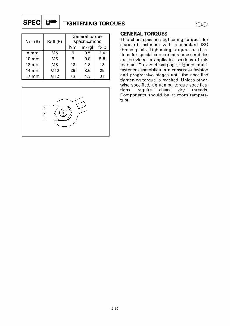
GENERAL TORQUES
This chart specifies tightening torques forstandard fasteners with a standard ISOthread pitch. Tightening torque specifica-tions for special components or assembliesare provided in applicable sections of thismanual. To avoid warpage, tighten multi-fastener assemblies in a crisscross fashionand progressive stages until the specifiedtightening torque is reached. Unless other-wise specified, tightening torque specifica-tions require clean, dry threads.Components should be at room tempera-ture.
Nut (A) Bolt (B)General torque specifications
Nm m•kgf ft•lb8 mm M5 5 0.5 3.610 mm M6 8 0.8 5.812 mm M8 18 1.8 1314 mm M10 36 3.6 2517 mm M12 43 4.3 31
2140


E
1 2 3 4 5 6 7 8 9
INSPADJ
CHAPTER 3
PERIODIC INSPECTIONS AND ADJUSTMENTS
MAINTENANCE INTERVAL CHART
.............................................................. 3-1
TOP COWLING
............................................................................................... 3-2INSPECTING THE TOP COWLING FIT.................................................... 3-2
FUEL SYSTEM
................................................................................................ 3-2INSPECTING THE FUEL LINE.................................................................. 3-2INSPECTING THE FUEL FILTER.............................................................. 3-3
CONTROL SYSTEM
........................................................................................ 3-3ADJUSTING THE IGNITION TIMING...................................................... 3-3SYNCHRONIZING THE CARBURETOR................................................... 3-6ADJUSTING THE ENGINE IDLING SPEED............................................. 3-7ADJUSTING THE CARBURETOR PICKUP TIMING................................ 3-9ADJUSTING THE REMOTE CONTROL SHIFT CABLE......................... 3-11ADJUSTING THE REMOTE CONTROL THROTTLE CABLE................. 3-11
COOLING SYSTEM
...................................................................................... 3-12INSPECTING THE COOLING WATER DISCHARGE ............................. 3-12
OIL INJECTION SYSTEM
............................................................................. 3-12SYNCHRONIZING THE OIL PUMP........................................................ 3-12AIR BLEEDING THE OIL INJECTION SYSTEM..................................... 3-13MEASURING THE OIL PUMP DISCHARGE.......................................... 3-14
POWER TRIM AND TILT SYSTEM
.............................................................. 3-16INSPECTING THE POWER TRIM AND TILT FLUID LEVEL.................. 3-16
LOWER UNIT
................................................................................................ 3-17INSPECTING THE GEAR OIL LEVEL ..................................................... 3-17CHANGING AND INSPECTING THE GEAR OIL ................................... 3-17INSPECTING THE LOWER UNIT (FOR AIR LEAKS)............................. 3-19
GENERAL
...................................................................................................... 3-19INSPECTING THE ANODES .................................................................. 3-19INSPECTING THE BATTERY ................................................................. 3-20INSPECTING THE SPARK PLUGS......................................................... 3-21LUBRICATION POINTS.......................................................................... 3-23

3-1
INSPADJ
E
MAINTENANCE INTERVAL CHART
MAINTENANCE INTERVAL CHART 3
Use the following chart as a guide to general maintenance intervals.Dependant on operating conditions, adjust the maintenance intervals accordingly.
Item RemarksInitial Every Refer
to page
10 hours (Break-in)
50 hours (3 months)
100 hours (6 months)
200 hours (1 year)
TOP COWLING
Top cowling fit Inspect 3-2
FUEL SYSTEM
Fuel line Inspect 3-2Fuel filter Clean/inspect 3-3Carburetor Clean 4-17
POWER UNIT
Water leakage Inspect —Motor exterior Inspect —Exhaust leakage Inspect —Cooling water passage Clean/flush —
CONTROL SYSTEM
Carburetor synchroni-zation
Inspect/adjust 3-6
Engine idling speed Inspect/adjust 3-7Remote control shift cable
Inspect/adjust 3-11
Remote control throttle cable
Inspect/adjust 3-11
OIL INJECTION SYSTEM
Oil tank water drain Clean —Oil pump lever Inspect/adjust 3-12
POWER TRIM AND TILT UNIT
Power trim and tilt fluid Inspect 3-16
LOWER UNIT
Gear oil Change 3-17Lower unit leakage Inspect 3-19Propeller Inspect 6-3, 6-27,
6-51
GENERAL
Anodes Inspect/replace 3-19Battery Inspect/charge (every month) 3-20Spark plugs Clean/adjust/replace 3-21Wiring and connectors Adjust/reconnect —Bolts and nuts Tighten —Lubrication points Grease 3-23

3-2
EINSPADJ
TOP COWLING/FUEL SYSTEM
TOP COWLING 3
INSPECTING THE TOP COWLING FIT 3
1. Inspect:• Top cowling fitting
Loose/unlatched
→
Adjust the topcowling hook.
3010
2. Adjust:• Top cowling hook position
Adjustment steps
(1) Loosen the bolts
1
approximately 1/4of a turn.
(2) Move the top cowling hook either upor down slightly.
(3) Secure the bolts.(4) Check the top cowling fitting and
repeat the adjustment if necessary.
NOTE:
• Moving the latch towards the seal willloosen the top cowling.
• Moving the latch away from the seal will
tighten the top cowling.
3020
FUEL SYSTEM 3
INSPECTING THE FUEL LINE 3
1. Inspect:• Plastic locking tie
Loosen
→
Retighten or replace.2. Inspect:
• Fuel lineCracks/damage/leaks
→
Replace.Refer to “FUEL JOINT AND FUEL FIL-TER” on page 4-1.Refer to “FUEL PUMP” on page 4-6.
3030

3-3
EINSPADJ
FUEL SYSTEM/CONTROL SYSTEM
INSPECTING THE FUEL FILTER 3
Inspect:• Fuel filter element• Fuel filter cup
Clogs/cracks/leaks
→
Replace.Foreign matter
→
Clean.Refer to “FUEL JOINT AND FUEL FIL-TER” on page 4-1.
3040
CONTROL SYSTEM 3
ADJUSTING THE IGNITION TIMING 3
1. Inspect:• Ignition timing (full advance)
Incorrect
→
Adjust.
Inspecting steps
(1) Remove the flywheel magnet assem-bly cover.
(2) Turn the flywheel magnet assembly
1
clockwise and align the timing plate
2
with the specified mark.
(3) Turn the magneto control lever
3
sothat it contacts the full advance adjust-ing screw
4
.(4) Check that the mark
a
on the flywheelmagnet assembly aligns with the mark
b
on the pulser coil assembly.
Flywheel magnet assembly position
150A, L150A, 175A/C150TR: BTDC 19˚200A, L200A: BTDC 18˚150F, L150F, D150H, 175D, S175D/D150TR, S175TR: BTDC 22˚S150F, LS150F, 175F, 200G/S150TR, L150TR, P175TR, P200TR: BTDC 23˚150G, 200F, L200F/P150TR, 200TR: BTDC 20˚S200F, LS200F, 225D/S200TR, L200TR: BTDC 21˚
3050
3051

3-4
EINSPADJ
CONTROL SYSTEM
2. Adjust:• Ignition timing (full advance)
Adjustment steps
(1) Remove all of the spark plugs.(2) Remove the intake silencer.(3) Install the dial gauge
1
into cylinder#1’s spark plug hole.
(4) Slowly turn the flywheel magnetassembly clockwise and stop it whenthe piston is at TDC.
(5) Set the dial gauge to “0”.(6) Turn the flywheel magnet assembly
clockwise until the dial gauge indicatesthe proper specification.
NOTE:
Turn the flywheel magnet assembly clock-
wise to locate BTDC.
(7) Align the timing plate
2
with the spec-ified mark on the flywheel magnetassembly.
Piston position150A, L150A, 175A/C150TR: 2.28 mm (0.09 in)200A, L200A: 2.05 mm (0.08 in)150F, L150F, D150H, 175D, S175D/D150TR, S175TR: 3.05 mm (0.12 in)S150F, LS150F, 175F, 200G/S150TR, L150TR, P175TR, P200TR: 3.33 mm (0.13 in)150G, 200F, L200F/P150TR, 200TR: 2.53 mm (0.10 in)S200F, LS200F, 225D/S200TR, L200TR: 2.78 mm (0.11 in)
Timing plate position150A, L150A, 175A/C150TR: BTDC 19˚200A, L200A: BTDC 18˚150F, L150F, D150H, 175D, S175D/D150TR, S175TR: BTDC 22˚S150F, LS150F, 175F, 200G/S150TR, L150TR, P175TR, P200TR: BTDC 23˚150G, 200F, L200F/P150TR, 200TR: BTDC 20˚S200F, LS200F, 225D/S200TR, L200TR: BTDC 21˚
3052
3053

3-5
EINSPADJ
CONTROL SYSTEM
(8) Secure the timing plate.(9) Adjust the length
a
of the full advanceadjusting screw
3
to specification.
(10) Disconnect the magneto control link
4
from the pulser coil assembly
5
.(11) Turn the magneto control lever
6
sothat it contacts the full advance adjust-ing screw
3
.(12) Adjust the length of the magneto con-
trol link
4
so that the mark
b
on theflywheel magnet assembly aligns withthe mark
c
on the pulser coil assem-bly
5
.
Full advance adjusting screw length
a
150A, L150A, 175A/C150TR: 23.5 mm (0.93 in)200A, L200A: 25.0 mm (0.98 in)150F, L150F, S150F, LS150F/S150TR, L150TR: 21.5 mm (0.85 in)D150H/D150TR:
41.2 mm (1.62 in)150G, P150TR: 43.5 mm (1.71 in)200F, L200F/200TR:
24.0 mm (0.94 in)175F, 200G/P175TR, P200TR: 40.0 mm (1.57 in)S200F, LS200F, 225D/S200TR, L200TR:
42.5 mm (1.67 in)3054
3. Inspect:• Ignition timing (full retard)
Out of specification
→
Adjust.
Inspecting steps
(1) Turn the flywheel magnet assemblyclockwise and align the timing plateand the specified mark.
(2) Turn the magneto control lever
1
sothat the full retard adjusting screw
2
contacts the crankcase
3
.(3) Check that the mark
a
on the flywheelmagnet assembly aligns with the mark
b
on the pulser coil assembly.
Flywheel magnet assembly position
ATDC 7˚
3055

3-6
EINSPADJ CONTROL SYSTEM
4. Adjust:• Ignition timing (full retard)
Adjustment steps
(1) Turn the flywheel magnet assemblyclockwise and align the timing plateand the specified mark.
(2) Turn the magneto control lever 1 tothe full retard position.
(3) Adjust the full retard adjustingscrew 2 so that the mark a on the fly-wheel magnet assembly aligns withthe mark b on the pulser coil assem-bly.
Flywheel magnet assembly position
ATDC 7˚
3055
SYNCHRONIZING THE CARBURETOR3
NOTE:
Before synchronizing the carburetor, besure to adjust the ignition timing.
1. Inspect:• Carburetor synchronization
Incorrect → Adjust.
Inspecting steps
(1) Remove the intake silencer.(2) While turning the middle throttle lever,
check that all throttle valves becomefully closed at the same time.

3-7
EINSPADJ CONTROL SYSTEM
2. Adjust:• Carburetor synchronization
Adjustment steps
(1) Loosen the idle adjusting screw 1until it does not touch the throttle armstopper 2.
(2) Loosen the upper and lower carbure-tor’s throttle lever securing screws 3by turning them clockwise.
(3) While lightly pushing the middle car-buretor’s throttle lever in the directionof the arrow (fully closed), tighten theupper and lower carburetor’s throttlelever securing screws 3 by turningthem counterclockwise.
(4) Turn the middle throttle lever andmake sure that all of the throttle valvesare synchronized.
3060
ADJUSTING THE ENGINE IDLING
SPEED 3
NOTE:
Before adjusting the engine idling speed, besure to synchronize the carburetor and igni-tion timing.
CAUTION:
Twin-barrel carburetors have two indepen-
dent pilot screws. Therefore, all of the pilot
screws should be properly adjusted before
adjusting the carburetors.
1. Measure:• Engine idling speed
Out of specification → Adjust.
Engine idling speed700 ± 25 r/min
3070

3-8
EINSPADJ CONTROL SYSTEM
Measuring steps
(1) Start the engine and allow it to warmup for a few minutes.
(2) Install the tachometer onto the sparkplug lead of cylinder #1.
TachometerYU-08036-A / 90890-06760
2. Adjust:• Engine idling speed
Adjustment steps
(1) Turn in the pilot screw 1 until it islightly seated.
(2) Turn out the pilot screw 1 the speci-fied number of turns.
Pilot screw (turns out)150A, L150A, 150F/C150TR: 1 ± 1/4S150F, LS150F/S150TR, L150TR: 1-1/4 ± 1/4150G, D150H/P150TR, D150TR:
(S) 1-9/16 ± 1/4(P) 1-1/16 ± 1/4
175A, 175D: 1-1/16 ± 1/4S175D/S175TR: 1-1/8 ± 1/4200A, L200A, 200F,L200F/200TR: 1-1/8 ± 1/4175F/P175TR: (S) 1-5/8 ± 1/4
(P) 1-1/8 ± 1/4S200F, LS200F/S200TR, L200TR: (S) 1-1/8 ± 1/4
(P) 5/8 ± 1/4200G, 225D/P200TR:
(S) 1-1/4 ± 1/4(P) 3/4 ± 1/4
3071
(3) Loosen the throttle roller adjustingscrew 2.
NOTE:
Depending on the model, refer to theappropriate illustration (Å or ı).
3072
Å ı

3-9
EINSPADJ
(4) Start the engine and allow it to warmup for a few minutes.
(5) Install the tachometer onto the sparkplug lead of cylinder #1.
(6) Turn the magneto control lever 3 sothat the full retard adjusting screw 4contacts the crankcase 5.
(7) Turn the throttle stop screw in or outuntil the specified engine idling speedis obtained.
(8) Tighten the throttle roller adjustingscrew 2.
TachometerYU-08036-A / 90890-06760
Turning inEngine idling speed
increases.
Turning outEngine idling speed
decreases.
Engine idling speed700 ± 25 r/min
3073
ADJUSTING THE CARBURETOR
PICKUP TIMING 3
NOTE:
Before adjusting the carburetor pickup tim-ing, be sure to adjust the ignition timing,carburetor synchronization and engineidling speed.
1. Inspect:• Pickup timing
Incorrect → Adjust.
CONTROL SYSTEM

3-10
EINSPADJ CONTROL SYSTEM
Inspecting steps
(1) Turn the magneto control lever so thatthe full retard adjusting screw contactsthe crankcase.
(2) Check that the mark a on the throttlecam aligns with the center of the throt-tle roller 1.
NOTE:
Depending on the model, refer to theappropriate illustration (Å or ı).
2. Adjust:• Pickup timing
Adjustment steps
(1) Adjust the throttle cam control link 1to the specified length a.
(2) Turn the magneto control lever 2 sothat the full retard adjusting screw 3contacts the crankcase 4.
(3) Loosen the throttle roller adjustingscrew 5.
(4) Align the mark a on the throttlecam 6 with the center of the throttleroller 7.
(5) Tighten the throttle roller adjustingscrew 5.
NOTE:
Depending on the model, refer to theappropriate illustration (Å or ı).
Throttle cam control link length150A, L150A, 150F, L150F, S150F, LS150F, 175A, 175D, S175D, 200A, L200A, 200F, L200F/C150TR, S150TR, L150TR, S175TR, 200TR:
42.5 mm (1.67 in)150G, D150H, 175F, 200G, S200F, LS200F, 225D/P150TR, D150TR, P175TR, P200TR, S200TR, L200TR:
52.5 mm (2.07 in)
Å ı
3080
3081
Å ı
3082

3-11
EINSPADJ
ADJUSTING THE REMOTE CONTROL
SHIFT CABLE 3
1. Inspect:• Shift operation
Incorrect → Adjust.2. Adjust:
• Remote control shift cable length
Adjustment steps
(1) Disconnect the shift cable joint 1.(2) Set the remote control lever to the
neutral position.(3) Align the center of the set pin a with
the mark b on the bottom cowling.(4) Adjust the position of the shift cable
joint until its hole aligns with the setpin c.
(5) Install the clip 2 and tighten the lock-nut 3.
CAUTION:
The remote control cable joint must be
screwed in more than 8 mm (0.31 in).
3120
3110
ADJUSTING THE REMOTE CONTROL
THROTTLE CABLE 3
NOTE:
Before adjusting the remote control throttlecable, be sure to adjust the ignition timingand carburetor synchronization.
1. Inspect:• Throttle operation
Incorrect → Adjust.
Inspecting steps
(1) Turn the throttle lever fully.(2) Check the magneto control lever 1 so
that it contacts the full advance adjust-ing screw 2.
3121
CONTROL SYSTEM
3-12
EINSPADJ CONTROL SYSTEM/COOLING SYSTEM
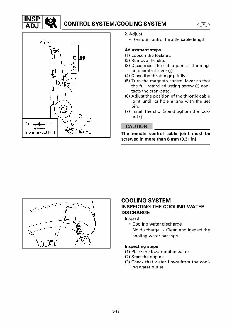
2. Adjust:• Remote control throttle cable length
Adjustment steps
(1) Loosen the locknut.(2) Remove the clip.(3) Disconnect the cable joint at the mag-
neto control lever 1.(4) Close the throttle grip fully.(5) Turn the magneto control lever so that
the full retard adjusting screw 2 con-tacts the crankcase.
(6) Adjust the position of the throttle cablejoint until its hole aligns with the setpin.
(7) Install the clip 3 and tighten the lock-nut 4.
CAUTION:
The remote control cable joint must be
screwed in more than 8 mm (0.31 in).
3122
COOLING SYSTEM 3INSPECTING THE COOLING WATER
DISCHARGE 3
Inspect:• Cooling water discharge
No discharge → Clean and inspect thecooling water passage.
Inspecting steps
(1) Place the lower unit in water.(2) Start the engine.(3) Check that water flows from the cool-
ing water outlet.
3140

3-13
EINSPADJ OIL INJECTION SYSTEM
OIL INJECTION SYSTEM 3SYNCHRONIZING THE OIL PUMP 3
1. Inspect:• Oil pump lever position
Incorrect → Adjust.
NOTE:
Make sure the oil pump lever 1 touches thestopper a (fully closed position) when thethrottle valves are closed.
2. Adjust:• Oil pump lever position
Adjustment steps
(1) Disconnect the oil pump link rod joint2.
(2) Fully close the throttle valves.(3) Turn the oil pump lever 1 so it con-
tacts the stopper a (fully closed posi-tion).
(4) Adjust the position of the oil pump linkrod joint until its hole aligns with theset pin on the oil pump lever 1.
(5) Tighten the locknut 3.(6) Install the washer and clip.
CAUTION:
After adjustment, make sure the oil pump
lever operates properly.
a
1
3150
3160
AIR BLEEDING THE OIL INJECTION
SYSTEM 3
Bleed:• Air bubbles
(from the oil injection system)

3-14
EINSPADJ OIL INJECTION SYSTEM
Bleeding steps
(1) Fill the fuel tank with the fuel/oil mix-ture (50:1).
CAUTION:
Only use the fuel/oil mixture (50:1) or
engine malfunctions or seizure may result.
(2) Disconnect the oil pump link rod jointfrom the oil pump lever.
(3) Start the engine.(4) Turn the oil pump lever 1 and keep it in
the fully-opened position until the fuel/oil mixture flows out of the oil pumpfeed hoses.
MEASURING THE OIL PUMP
DISCHARGE 3
Measure:• Oil pump discharge
Out of specification → Check all of theoil pump components and replace anydefective parts.
Recommended fuelFuel type
Unleaded regular gasolineFuel rating
PON: 86RON: 91
Recommended engine oilEngine oil type
2-stroke outboard engine oilEngine oil grade
TC-W3
Engine oil discharge (3 minutes/1 cylinder)
150F, L150F, S150F, LS150F, 150G, 175F, D150H, 175D, S175D/S150TR, L150TR, P150TR, P175TR, D150TR, S175TR
3.40 ± 0.70 cm3 (0.115 ± 0.024 US oz,0.120 ± 0.025 Imp oz)
200F, L200F, S200F, LS200F, 200G, 225D/200TR, S200TR, L200TR, P200TR
4.80 ± 1.10 cm3 (0.162 ± 0.037 US oz, 0.169 ± 0.039 Imp oz)
3180

3-15
EINSPADJ OIL INJECTION SYSTEM
NOTE:
When measuring the oil pump discharge,observe the following.• The engine oil temperature should be 10 -
30 ˚C (50 - 86 ˚F).• Before measuring the oil pump discharge,
completely bleed any air from the oilinjection system and make sure that no airbubbles are present in the engine oilwhich is flowing out of the oil feed hose.
• When using the graduated cylinder, makesure no engine oil clings to its walls; oth-erwise, the measurement will be incor-rect.
• Use only the specified engine oil of theproper viscosity. If the viscosity is toohigh or too low, the discharge measure-ment will be incorrect.
• Calculate the rate of discharge per minute.The longer the measurement time, thehigher the accuracy of the measurement.
Measuring steps
(1) Fill the fuel tank with the fuel/oil mix-ture (50:1) and fill the oil tank withengine oil.
CAUTION:
Only use the fuel/oil mixture (50:1) or
engine malfunctions or seizure may result.
(2) Disconnect the oil pump link rod jointfrom the oil pump lever.
(3) Move the oil pump lever 1 to the fully-opened position.
Recommended fuelFuel type
Unleaded regular gasolineFuel rating
PON: 86RON: 91
Recommended engine oilEngine oil type
2-stroke outboard engine oilEngine oil grade
TC-W3
3190
3180
3-16
EINSPADJ
OIL INJECTION SYSTEM/
POWER TRIM AND TILT SYSTEM
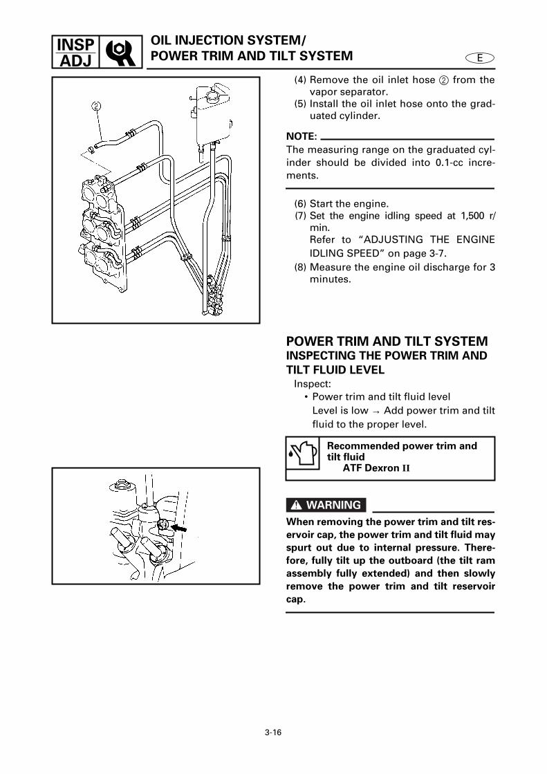
(4) Remove the oil inlet hose 2 from thevapor separator.
(5) Install the oil inlet hose onto the grad-uated cylinder.
NOTE:
The measuring range on the graduated cyl-inder should be divided into 0.1-cc incre-ments.
(6) Start the engine.(7) Set the engine idling speed at 1,500 r/
min.Refer to “ADJUSTING THE ENGINEIDLING SPEED” on page 3-7.
(8) Measure the engine oil discharge for 3minutes.
3185
POWER TRIM AND TILT SYSTEM3INSPECTING THE POWER TRIM AND
TILT FLUID LEVEL 3
Inspect:• Power trim and tilt fluid level
Level is low → Add power trim and tiltfluid to the proper level.
WARNING
When removing the power trim and tilt res-
ervoir cap, the power trim and tilt fluid may
spurt out due to internal pressure. There-
fore, fully tilt up the outboard (the tilt ram
assembly fully extended) and then slowly
remove the power trim and tilt reservoir
cap.
Recommended power trim and tilt fluid
ATF Dexron II
3195

3-17
EINSPADJ
POWER TRIM AND TILT SYSTEM/
LOWER UNIT
Inspecting steps
(1) Tilt the outboard all the way up andlock it with the tilt stop levers 1.
WARNING
After tilting up the outboard, be sure to
support it with the tilt stop levers.
Otherwise, the outboard could suddenly
lower if the power trim and tilt unit should
lose fluid pressure.
(2) Remove the reservoir cap 2 andinspect the fluid level.
NOTE:
The fluid level should be directly below thecheck hole as shown.
(3) Add power trim and tilt fluid if needed,and then install the reservoir cap.
T R.
.
Reservoir cap8 Nm (0.8 m • kgf, 5.8 ft • lb)
3196
3210
LOWER UNIT 3INSPECTING THE GEAR OIL LEVEL 3
Inspect:• Gear oil level
Level is low → Add gear oil to theproper level.
CHANGING AND INSPECTING THE
GEAR OIL 3
1. Inspect:• Gear oil
Milky oil → Replace the oil seal. Slag oil → Check the gears, bearings,and clutch dog.

3-18
EINSPADJ LOWER UNIT
Inspecting steps
(1) Tilt up the outboard slightly.(2) Place a container under the gear oil
drain screw 1.(3) Remove the gear oil drain screw and
gear oil level check screw 2.
2. Fill:• Gear oil
(with the specified amount of the rec-ommend gear oil)
Recommended gear oilGEAR CASE LUBE (USA) or Hypoid gear oil, SAE 90
Total amountRegular rotation models
980 cm3 (33.1 US oz, 34.5 Imp oz)
Counter rotation models870 cm3 (29.4 US oz, 30.6 Imp oz)
Dual propeller models900 cm3 (30.4 US oz, 31.7 Imp oz)
3220
Filling steps
(1) Place the outboard in an upright posi-tion.
(2) Insert the gear oil tube into the drainhole and slowly fill the gear oil until oilflows out of the check hole and no airbubbles are visible.
(3) Install the gear oil level check screwand then quickly install the gear oildrain screw.
T R.
.
Gear oil level check screw7 Nm (0.7 m • kgf, 5.1 ft • lb)
Gear oil drain screw7 Nm (0.7 m • kgf, 5.1 ft • lb)
3230

3-19
EINSPADJ LOWER UNIT/GENERAL
INSPECTING THE LOWER UNIT
(FOR AIR LEAKS) 3
Inspect:• Lower unit holding pressure
Pressure drops → Inspect the sealsand components.
Inspecting steps
CAUTION:
Do not overpressurize the lower unit.
Excessive pressure may damage the oil
seals.
(1) Remove the gear oil level check screw.(2) Install the pressure tester into the
check hole.
(3) Apply the specified pressure.
NOTE:
The lower unit should hold the specifiedpressure for 10 seconds.
Lower unit holding pressure100 kPa (1.0 kg/cm2, 14.2 psi)
Pressure testerYB-35956 / 90890-06762
3240
GENERAL 3INSPECTING THE ANODES 3
Inspect:• Anodes 1 • Trim tab 2
(except for D150H/D150TR)Scales → Clean.Grease/oil → Clean.Excessive wear → Replace.
CAUTION:
Do not oil, grease or paint the anode, or it
will not operate properly.
3250

3-20
EINSPADJ GENERAL
INSPECTING THE BATTERY 3
WARNING
Battery electrolytic fluid is dangerous; it
contains sulfuric acid and therefore is poi-
sonous and highly caustic.
Always follow these preventive measures:
• Avoid bodily contact with electrolytic
fluid as it can cause severe burns or per-
manent eye injury.
• Wear protective eye gear when handling
or working near batteries.
Antidote (EXTERNAL):
• SKIN - Flush with water.
• EYES - Flush with water for 15 minutes
and get immediate medical attention.
Antidote (INTERNAL):
• Drink large quantities of water or milk fol-
lowed by milk of magnesia, beaten egg,
or vegetable oil. Get immediate medical
attention.
Batteries also generate explosive hydrogen
gas; therefore, you should always follow
these preventive measures:
• Charge batteries in a well-ventilated area.
• Keep batteries away from fire, sparks, or
open flames (e.g., welding equipment,
lighted cigarettes, etc.).
• DO NOT SMOKE when charging or han-
dling batteries.
KEEP BATTERIES AND ELECTROLYTIC
FLUID OUT OF REACH OF CHILDREN.
NOTE:
• Batteries vary among manufacturers.Therefore, the following procedures maynot always apply. Consult your batterymanufacturer’s instructions.
• First, disconnect the negative lead, thenthe positive lead.

3-21
EINSPADJ GENERAL
Inspect:• Electrolyte level
Below the minimum level mark →Add distilled water to the proper level.
• Electrolyte specific gravityLess than specification → Rechargethe battery.
Electrolyte specific gravity1.280 at 20˚C (68˚F)
INSPECTING THE SPARK PLUGS 3
1. Inspect:• Electrodes 1
Cracks/excessive wear → Replace. • Insulator color 2
Distinctly different color → Check the engine condition.
2. Clean:• Spark plug
(with a spark plug cleaner or wirebrush.)
Color guideMedium to light tan color
NormalWhitish color
• Lean fuel mixture• Plugged jet(-s)• Air leak• Wrong setting
Blackish color• Rich mixture• Excessive oil usage• Defective ignition system• Defective spark plug
3260

3-22
EINSPADJ GENERAL
3. Measure:• Spark plug gap a
Out of specification → Regap.
Spark plug gap0.9 - 1.0 mm (0.035 - 0.039 in)
3270
4. Tighten:• Spark plug
NOTE:
• Before installing the spark plug, clean thegasket surface and spark plug surface.Also, it is suggested to apply a thin film ofanti-seize compound to the spark plugthreads to prevent thread seizure.
• If a torque wrench is not available, a goodestimate of the correct tightening torqueis to finger tighten a the spark plug andthen tighten it another 1/4 to 1/2 of aturn b.
T R.
.
Spark plug25 Nm (2.5 m • kgf, 18 ft • lb)
3280

3-23
EINSPADJ GENERAL
LUBRICATION POINTS 3
Apply:• Water resistant grease
3290
3300
3310
3320
3330

E
1 2 3 4 5 6 7 8 9
FUEL
CHAPTER 4
FUEL SYSTEM
FUEL JOINT AND FUEL FILTER
.................................................................... 4-1REMOVING/INSTALLING THE FUEL JOINT AND FUEL FILTER (FOR PRE-MIX MODELS, EXCEPT FOR 225DET).................................. 4-1REMOVING/INSTALLING THE FUEL JOINT AND FUEL FILTER (FOR OIL INJECTION MODELS, AND 225DET)..................................... 4-3INSPECTING THE CHECK VALVE ........................................................... 4-5
FUEL PUMP
.................................................................................................... 4-6REMOVING/INSTALLING THE FUEL PUMP........................................... 4-6DISASSEMBLING/ASSEMBLING THE FUEL PUMP.............................. 4-7INSPECTING THE FUEL PUMPS............................................................. 4-9
OIL TANK
...................................................................................................... 4-10REMOVING/INSTALLING THE OIL TANK ............................................ 4-10
CARBURETOR
.............................................................................................. 4-12REMOVING/INSTALLING THE CARBURETOR..................................... 4-12DISASSEMBLING/ASSEMBLING THE CARBURETOR........................ 4-14INSPECTING THE CARBURETOR ......................................................... 4-17ASSEMBLING THE CARBURETOR....................................................... 4-17
OIL PUMP
...................................................................................................... 4-19REMOVING/INSTALLING THE OIL PUMP (FOR 150G, 175F, S200F, 200G, 225D/P150TR, P175TR, S200TR P200TR MODELS) ................................................................... 4-19REMOVING/INSTALLING THE OIL PUMP (EXCEPT FOR 150G, 175F, S200F, 200G, 225D/P150TR, P175TR, S200TR, P200TR MODELS) .................................................................. 4-21INSPECTING THE CHECK VALVE ......................................................... 4-23

4-1
FUEL
E
FUEL JOINT AND FUEL FILTER 4
REMOVING/INSTALLING THE FUEL JOINT AND FUEL FILTER
(FOR PRE-MIX MODELS, EXCEPT FOR 225DET)
Order Job/Part Q’ty Remarks1 Clip 12 Fuel hose 1 (fuel joint-to-fuel filter)3 Bolt 14 Fuel joint 15 Plastic locking tie 36 Fuel hose 1 (fuel filter-to-fuel pump)7 Bolt 18 Fuel filter 19 Bolt 1
Continued on next page.
4010
Not reusable
FUEL JOINT AND FUEL FILTER

4-2
FUEL
E
4
Order Job/Part Q’ty Remarks10 Fuel filter bracket 111 Fuel filter nut 112 Fuel filter cap 113 Fuel filter element 114 Spring 115 Float 116 O-ring 117 Fuel filter cup 1
For installation, reverse the removal procedure.
4010
FUEL JOINT AND FUEL FILTER

4-3
FUEL
E
FUEL JOINT AND FUEL FILTER
4
REMOVING/INSTALLING THE FUEL JOINT AND FUEL FILTER
(FOR OIL INJECTION MODELS, AND 225DET)
Order Job/Part Q’ty Remarks1 Clip 12 Fuel hose 1 (fuel joint-to-fuel filter)3 Bolt 14 Fuel joint 15 Plastic locking tie 36 Fuel hose 1 (fuel filter-to-fuel pump)7 Nut 1
Continued on next page.
4020
Not reusable

4-4
FUEL
E
4
Order Job/Part Q’ty Remarks8 Fuel filter 19 Bolt 110 Fuel filter bracket 111 Fuel filter cap 112 Fuel filter element 113 O-ring 114 Fuel filter cup 1
For installation, reverse the removal procedure.
4020
FUEL JOINT AND FUEL FILTER

4-5
FUEL
E
FUEL JOINT AND FUEL FILTER
INSPECTING THE CHECK VALVE
1. Inspect:• Fuel joint
Cracks/damage/leaks
→
Replace
.
2. Inspect• Fuel joint operation
Pressure cannot be maintained for 10seconds
→
Replace
.
Inspecting steps
NOTE:
Do not overpressurize the fuel joint. Exces-
sive pressure may cause air to leak out.
(1) Install the Mity vac onto the fuel jointas shown.
(2) Apply the specified pressure with theMity vac.
Mity vacYB-35956 / 90890-06756
Check valve pressure50 kPa (0.5 kg/cm
2
, 7.1 psi)
4030

4-6
FUEL
E
FUEL PUMP
FUEL PUMP 4
REMOVING/INSTALLING THE FUEL PUMP
Order Job/Part Q’ty Remarks1 Plastic locking tie 82 Fuel hose 2 (fuel filter-to-fuel pump)3 Fuel hose 2 (fuel pump-to-carburetor)4 Bolt 25 Fuel pump 26 Gasket 2
For installation, reverse the removal procedure.
4040
Not reusable
Not reusable

4-7
FUEL
E
4
DISASSEMBLING/ASSEMBLING THE FUEL PUMP
Order Job/Part Q’ty Remarks1 Screw 32 Diaphragm body 13 Diaphragm 14 Gasket 15 Fuel pump base 16 Gasket 17 Diaphragm 1
Continued on next page.
4220
Not reusable
Not reusable
FUEL PUMP

4-8
FUEL
E
FUEL PUMP
4
Order Job/Part Q’ty Remarks8 Spring seat 19 Spring 110 Screw 411 Fuel pump valve 412 Nut 413 Fuel pump body 1
For assembly, reverse the disassembly procedure.
4220

4-9
FUEL
E
FUEL PUMP
INSPECTING THE FUEL PUMPS
1. Inspect:• Diaphragm• Fuel pump valves
Damage
→
Replace.2. Inspect:
• Fuel pumpReverse air flow
→
Replace.
Inspecting steps
NOTE:
Do not overpressurize the fuel pump.Excessive pressure may cause air to leak
out.
(1) Install the Mity vac onto the fuel pumpas shown.
(2) Apply the specified pressure with theMity vac.
NOTE:
• Make sure no air comes out of the oppo-site side of the fuel pump.
• To eliminate any gaps between the fuelpump valves and the fuel pump body, andto ensure a better seal, make sure theinside of the fuel pump is wet (i.e., with
gas).
Mity vacYB-35956 / 90890-06756
Fuel pump pressure
a
50 kPa (0.5 kg/cm
2
, 7.1 psi)Fuel pump negative pressure
b
30 kPa (0.3 kg/cm
2
, 4.3 psi)4240

4-10
FUEL
E
OIL TANK 4
REMOVING/INSTALLING THE OIL TANK
Order Job/Part Q’ty RemarksFlywheel magnet assembly cover Refer to “FLYWHEEL MAGNET
ASSEMBLY” on page 5-1.CDI unit cover Refer to “STATOR ASSEMBLY” on page
5-8.1 Oil level sensor coupler 12 Oil level sensor 13 Oil strainer 14 Washer 15 Oil tank air vent hose 1 (oil tank-to-intake silencer)6 Plastic locking tie 17 Oil hose 1 (sub oil tank-to-oil tank)
Continued on next page.
4060
Not reusable
OIL TANK

4-11
FUEL
E
OIL TANK
4
Order Job/Part Q’ty Remarks8 Bolt 39 Collar 310 Grommet 311 Oil tank 112 Plastic locking tie 113 Oil hose 1 (oil tank-to-oil pump)
For installation, reverse the removal procedure.
4060
Not reusable

4-12
FUEL
E
CARBURETOR 4
REMOVING/INSTALLING THE CARBURETOR
Order Job/Part Q’ty Remarks1 Oil tank air vent hose 1 (intake silencer-to-oil tank)
Oil injection modes2 Intake manifold air vent hose 1 (intake silencer-to-intake manifold)3 Screw 124 Intake silencer 15 Rubber gasket 36 Oil pump link rod 1 Oil injection models7 Choke link rod 18 O-ring 19 Fuel enrichment valve rod 1
Continued on next page.
4070
CARBURETOR

4-13
FUEL
E
CARBURETOR
4
Order Job/Part Q’ty Remarks10 Fuel enrichment valve link rod 211 Throttle link rod 112 Nut 1213 Carburetor #1 114 Plastic locking tie 315 Gasket 316 Carburetor #2 117 Carburetor #3 1
For installation, reverse the removal procedure.
4070
Not reusable
Not reusable

4-14
FUEL
E
4
DISASSEMBLING/ASSEMBLING THE CARBURETOR
Order Job/Part Q’ty Remarks1 Screw 42 Float chamber 13 Float pin 24 Float 25 Needle valve 26 Clip 27 Gasket 18 Drank bolt 29 Gasket 2
Continued on next page.
4080
Not reusable
CARBURETOR

4-15
FUEL
E
CARBURETOR
4
Order Job/Part Q’ty Remarks10 Main jet 211 Pilot jet plug 212 Pilot jet 213 Screw 114 Carburetor top cover 115 Screw 216 Gasket 217 Screw 218 Spring 2
Continued on next page.
4080

4-16
FUEL
E
CARBURETOR
4
Order Job/Part Q’ty Remarks19 Screw 120 Gasket 121 Pilot air jet 222 Screw 223 Carburetor body 124 Throttle stop screw 125 Spring 1
For assembly, reverse the disassembly procedure.
4080

4-17
FUEL
E
CARBURETOR
INSPECTING THE CARBURETOR
CAUTION:
Do not use a steel wire to clean the jets.
This may enlarge the jet diameters and
seriously affect performance.
1. Inspect:• Carburetor body
Cracks/damage
→
Replace.Contamination
→
Clean.2. Inspect:
• Pilot screwBends/wear
→
Replace.3. Inspect:
• Main jet• Pilot jet• Pilot air jet
Contamination
→
Clean.4. Inspect:
• Needle valveGrooved wear
→
Replace.5. Inspect:
• FloatCracks/damage
→
Replace.
4090
4100
4110
ASSEMBLING THE CARBURETOR
1. Install:• Needle valve• Float• Float pin
NOTE:
• When installing the float into the carbure-tor, place the needle valve into the needlevalve seat.
• After installation, make sure that the float
operates smoothly.
4120

4-18
FUEL
E
CARBURETOR
2. Measure:• Float height a
(without the gasket)Out of specification → Adjust the floatheight by bending the tab 1.
NOTE:
• The float should be resting on the needlevalve, but not compressing it.
• Take measurements at the end of thefloat, opposite the side it pivots on.
Float height16.0 ± 0.5 mm (0.63 ± 0.02 in)
4130
3. Adjust:• Pilot screw
Adjustment steps
(1) Turn in the pilot screw until it is lightlyseated.
(2) Turn out the pilot screw to specifica-tion.
Pilot screw (turns out)150A, L150A, 150F/C150TR: 1 ± 1/4S150F, LS150F/S150TR, L150TR: 1-1/4 ± 1/4150G, D150H/P150TR, D150TR:
(S) 1-9/16 ± 1/4(P) 1-1/16 ± 1/4
175A, 175D: 1-1/16 ± 1/4S175D/S175TR: 1-1/8 ± 1/4200A, L200A, 200F,L200F/200TR: 1-1/8 ± 1/4175F/P175TR: (S) 1-5/8 ± 1/4
(P) 1-1/8 ± 1/4S200F, LS200F/S200TR, L200TR: (S) 1-1/8 ± 1/4
(P) 5/8 ± 1/4200G, 225D/P200TR:
(S) 1-1/4 ± 1/4(P) 3/4 ± 1/4
4140

4-19
FUEL EOIL PUMP
OIL PUMP 4REMOVING/INSTALLING THE OIL PUMP (FOR 150G, 175F, S200F, 200G, 225D/
P150TR, P175TR, S200TR P200TR MODELS)
Order Job/Part Q’ty Remarks1 Clip 12 Washer 13 Oil pump link rod 14 Oil hose 1 (oil tank-to-oil pump)5 Bolt 26 Oil pump 1
Continued on next page.
4150

4-20
FUEL EOIL PUMP
4
Order Job/Part Q’ty Remarks7 Oil pump drive gear 18 Metal plate 19 O-ring 110 Clip 2411 Oil delivery hose 12 (oil pump-to-intake manifold)12 Check valve 6
For installation, reverse the removal procedure.
4150
Not reusable
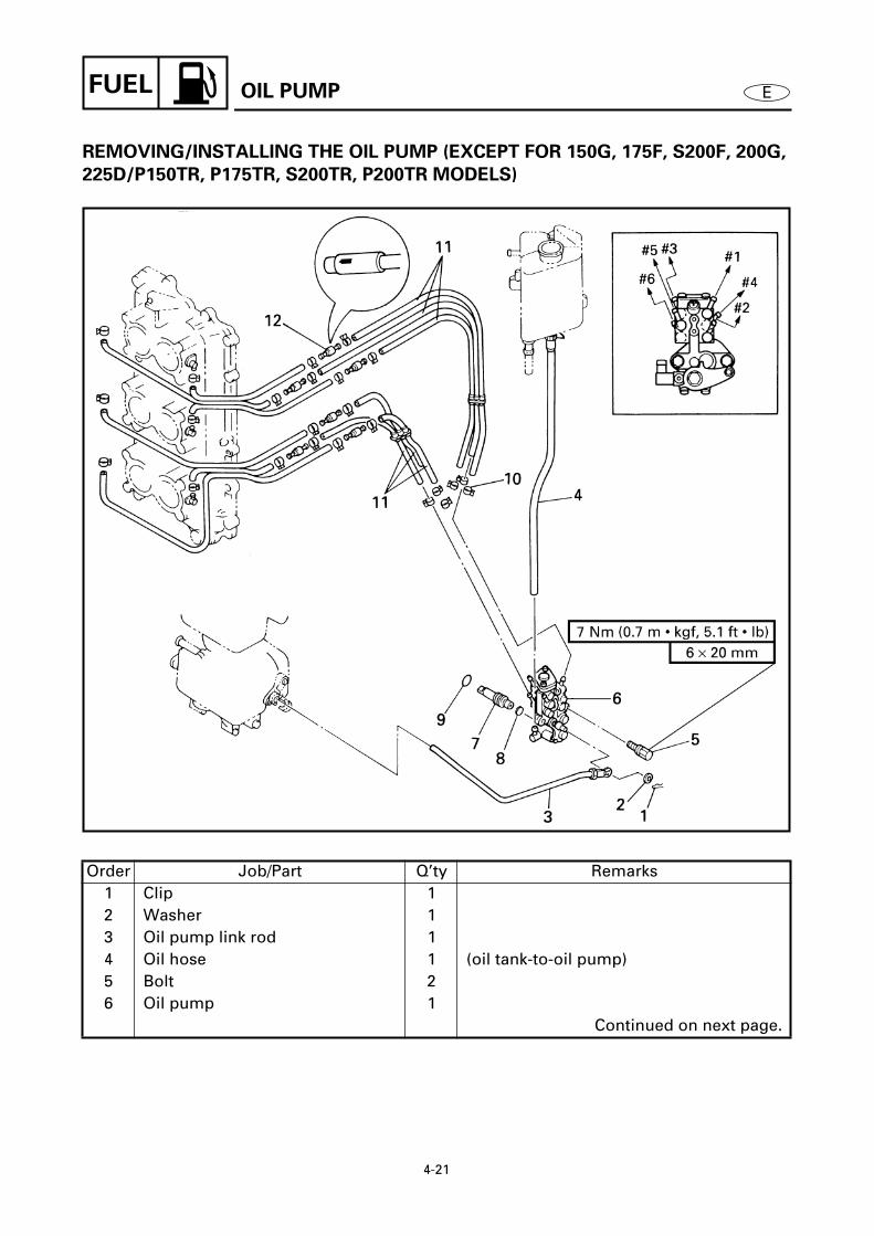
4-21
FUEL EOIL PUMP
4REMOVING/INSTALLING THE OIL PUMP (EXCEPT FOR 150G, 175F, S200F, 200G,
225D/P150TR, P175TR, S200TR, P200TR MODELS)
Order Job/Part Q’ty Remarks1 Clip 12 Washer 13 Oil pump link rod 14 Oil hose 1 (oil tank-to-oil pump)5 Bolt 26 Oil pump 1
Continued on next page.
4160

4-22
FUEL EOIL PUMP
4
Order Job/Part Q’ty Remarks7 Oil pump drive gear 18 Metal plate 19 O-ring 110 Clip 2411 Oil delivery hose 12 (oil pump-to-intake manifold)12 Check valve 6
For installation, reverse the removal procedure.
4160
Not reusable

4-23
FUEL EOIL PUMP
INSPECTING THE CHECK VALVE
Inspect:• Check valve operation
Damage/reverse air flow → Replace.
Inspecting steps
NOTE:
Do not overpressurize the check valve.Excessive pressure may cause air to leakout.
(1) Install the Mity vac onto the checkvalve as shown.
(2) Apply the specified pressure with theMity vac.
NOTE:
Make sure no air comes out of the oppositeside of the check valve.
Mity vacYB-35956 / 90890-06756
Check valve pressure80 kPa (0.8 kg/cm2, 11.4 psi)
4230


EPOWR
CHAPTER 5
POWER UNIT
FLYWHEEL MAGNET ASSEMBLY
................................................................ 5-1REMOVING/INSTALLING THE FLYWHEEL MAGNET ASSEMBLY ...... 5-1REMOVING THE FLYWHEEL MAGNET ASSEMBLY............................. 5-2INSTALLING THE FLYWHEEL MAGNET ASSEMBLY ........................... 5-3
POWER UNIT
.................................................................................................. 5-4DISCONNECTING/CONNECTING THE LEADS ...................................... 5-4DISCONNECTING/CONNECTING THE HOSES...................................... 5-5REMOVING/INSTALLING THE POWER UNIT ........................................ 5-6
STATOR ASSEMBLY
...................................................................................... 5-8REMOVING/INSTALLING THE STATOR ASSEMBLY............................ 5-8
CDI UNIT
....................................................................................................... 5-10REMOVING/INSTALLING THE CDI UNIT ASSEMBLY......................... 5-10REMOVING/INSTALLING THE CDI UNIT ............................................. 5-12
RECTIFIER/REGULATOR
............................................................................. 5-14REMOVING/INSTALLING THE RECTIFIER/REGULATOR .................... 5-14
RELAY ASSEMBLY AND STARTER MOTOR
.............................................. 5-16REMOVING/INSTALLING THE RELAY ASSEMBLY AND STARTER MOTOR................................................................................. 5-16
CONTROL UNIT
............................................................................................ 5-18REMOVING/INSTALLING THE CONTROL UNIT.................................. 5-18INSTALLING THE CONTROL UNIT....................................................... 5-20
INTAKE MANIFOLD
...................................................................................... 5-21REMOVING/INSTALLING THE INTAKE MANIFOLD (FOR 150G, 175F, S200F, 200G, 225D/P150TR, P175TR, S200TR, P200TR MODELS) .................................................................. 5-21REMOVING/INSTALLING THE INATAKE MANIFOLD (EXCEPT FOR 150G, 175F, S200F, 200G, 225D/P150TR, P175TR, S200TR, P200TR MODELS) .................................................................. 5-23

E
1 2 3 4 5 6 7 8 9
POWR
REED VALVES
.............................................................................................. 5-25REMOVING/INSTALLING THE REED VALVES..................................... 5-25INSPECTING THE REED VALVE ASSEMBLY....................................... 5-26
CYLINDER HEADS
........................................................................................ 5-27REMOVING/INSTALLING THE CYLINDER HEADS.............................. 5-27INSPECTING THE THERMOSTATS ...................................................... 5-29INSPECTING THE CYLINDER HEADS................................................... 5-29
EXHAUST COVERS
...................................................................................... 5-31REMOVING/INSTALLING THE EXHAUST COVERS ............................ 5-31INSPECTING THE PRESSURE CONTROL VALVE................................ 5-33
CRANKCASE
................................................................................................. 5-34REMOVING/INSTALLING THE CRANKCASE....................................... 5-34ASSEMBLING THE OIL SEAL HOUSING ............................................. 5-36INSTALLING THE CRANKCASE............................................................ 5-36
CYLINDER BODY ASSEMBLY
..................................................................... 5-37DISASSEMBLING/ASSEMBLING THE CYLINDER BODY ASSEMBLY............................................................................................ 5-37DISASSEMBLING/ASSEMBLING THE PISTON AND CONNECTING ROD ASSEMBLIES....................................................... 5-40DISASSEMBLING/ASSEMBLING THE CRANKSHAFT ASSEMBLY............................................................................................ 5-41DISASSEMBLING THE UPPER BEARING HOUSING .......................... 5-42REMOVING THE BEARING AND OIL PUMP DRIVE GEAR.................. 5-42INSPECTING THE CYLINDER BODY..................................................... 5-43INSPECTING THE PISTONS.................................................................. 5-44CALCULATING THE PISTON-TO-CYLINDER CLEARANCE................. 5-44INSPECTING THE PISTON PINS AND SMALL-END BEARINGS ........ 5-45INSPECTING THE PISTON RINGS........................................................ 5-45INSPECTING THE OIL PUMP DRIVEN GEAR....................................... 5-46INSPECTING THE LABYRINTH RINGS................................................. 5-47INSPECTING THE CRANKSHAFT ......................................................... 5-47INSTALLING THE OIL PUMP DRIVE GEAR.......................................... 5-48INSTALLING THE BEARING.................................................................. 5-48INSTALLING THE PISTON RINGS AND PISTON................................. 5-48ASSEMBLING THE UPPER BEARING HOUSING ................................ 5-49INSTALLING THE CRANKSHAFT ASSEMBLY..................................... 5-50INSTALLING THE PISTON AND CONNECTING ROD ASSEMBLIES......................................................................................... 5-50

5-1
POWR
E
FLYWHEEL MAGNET ASSEMBLY
FLYWHEEL MAGNET ASSEMBLY 5
REMOVING/INSTALLING THE FLYWHEEL MAGNET ASSEMBLY 5
Å
S150F, LS150F, S175D, S200F, LS200F/S150TR, L150TR, S175TR, S200TR, L200TR
ı
Oil injection and 225DET models
Ç
Pre-mix except for 225DET models
Order Job/Part Q’ty Remarks1 Flywheel magnet assembly cover 12 Flywheel magnet assembly nut 13 Washer 14 Flywheel magnet assembly 15 Woodruff key 1
For installation, reverse the removal procedure.
5010

5-2
POWR
E
FLYWHEEL MAGNET ASSEMBLY
REMOVING THE FLYWHEEL
MAGNET ASSEMBLY 5
Remove:• Flywheel magnet assembly
Removing steps
(1) Remove the flywheel magnet assem-bly nut.
Å
For USA and Canada
ı
Except for USA and Canada
NOTE:
The major load should be applied in thedirection of the arrows. If the load is notapplied as shown, the flywheel magnetassembly holder may easily slip off of the
flywheel magnet assembly.
(2) Remove the flywheel magnet assem-bly.
Å
For USA and Canada
ı
Except for USA and Canada
NOTE:
• The major load should be applied in thedirection of the arrows.
• Apply the load until the flywheel magnetassembly comes off the tapered portion of
the crankshaft.
CAUTION:
To prevent damage to the engine or tools,
screw in the universal puller set-bolts
evenly and completely so that the puller
plate is parallel to the flywheel magnet
assembly.
Flywheel magnet assembly holder
YB-06139 / 90890-06522
Universal pullerYB-06117 / 90890-06521
Å
5020
ı
5030
Å ı
5040
5050

5-3
POWR
E
INSTALLING THE FLYWHEEL
MAGNET ASSEMBLY 5
Install:• Flywheel magnet assembly nut
Å
For USA and Canada
ı
Except for USA and Canada
NOTE:
The major load should be applied in thedirection of the arrows. If the load is notapplied as shown, the flywheel magnetassembly holder may easily slip off of the
flywheel magnet assembly.
Flywheel magnet assembly holder
YB-06139 / 90890-06522
T R.
.
Flywheel magnet assembly nut (oil injection and 225DET models)
190 Nm (19 m • kgf, 137 ft • lb)Flywheel magnet assembly nut (pre-mix except for 225DET models)
165 Nm (16.5 m • kgf, 120 ft • lb)
Å
5060
ı
5070
FLYWHEEL MAGNET ASSEMBLY

5-4
POWR
E
POWER UNIT 5
DISCONNECTING/CONNECTING THE LEADS 5
Order Job/Part Q’ty RemarksBattery leads (from the battery)Remote control shift and throttle rods and cables
1 Choke rod 12 Remote control coupler 13 Trim sensor coupler and
connector2
4 Negative battery lead 15 Positive battery lead 1
For installation, reverse the removal procedure.
5080
POWER UNIT

5-5
POWR
E
5
DISCONNECTING/CONNECTING THE HOSES 5
Order Job/Part Q’ty Remarks1 Pilot water hose 12 Cooling water hose 13 Bolt 14 Metal clamp 15 Ground lead 16 Trailer switch coupler 17 Bolt 18 Cable guide 19 Power trim and tilt lead 1 (blue)10 Power trim and tilt lead 1 (green)
For installation, reverse the removal procedure.
5090
POWER UNIT

5-6
POWR
E
POWER UNIT
5
REMOVING/INSTALLING THE POWER UNIT 5
Order Job/Part Q’ty Remarks1 Bolt 22 Bolt 23 Bolt 24 Forward apron 15 Bolt 26 Bolt 27 Rear apron 1
Continued on next page.
5100

5-7
POWR
E
POWER UNIT
5
5
Order Job/Part Q’ty Remarks8 Nut 29 Bolt 410 Bolt 611 Power unit 112 Gasket 113 Dowel pin 2
For installation, reverse the removal procedure.
5100
Not reusable

5-8
POWR
E
STATOR ASSEMBLY 5
REMOVING/INSTALLING THE STATOR ASSEMBLY 5
Order Job/Part Q’ty RemarksFlywheel magnet assembly Refer to “FLYWHEEL MAGNET
ASSEMBLY” on page 5-1.1 Screw 42 CDI unit cover 13 Crank position sensor connector 2 Oil injection and 225DET models4 Screw 2 Oil injection and 225DET models5 Crank position sensor 1 Oil injection and 225DET models6 Charge coil coupler 17 Lighting coil coupler 1
Continued on next page.
5110
STATOR ASSEMBLY

5-9
POWR
E
STATOR ASSEMBLY
5
5
Order Job/Part Q’ty Remarks8 Bolt 49 Stator assembly 110 Pulser coil coupler 111 Screw 412 Pulser coil bushing retainer 413 Pulser coil assembly 114 Pulser coil bushing 1
For installation, reverse the removal procedure.
5110

5-10
POWR
E
CDI UNIT 5
REMOVING/INSTALLING THE CDI UNIT ASSEMBLY 5
Order Job/Part Q’ty RemarksCDI unit cover Refer to “DISCONNECTING/CONNECT-
ING THE HOSES” on page 5-5.1 Crank position sensor connector 22 Charge coil coupler 13 Pulser coil coupler 14 Bolt 25 Ground lead 26 Spark plug cap 6
Continued on next page.
5120
CDI UNIT
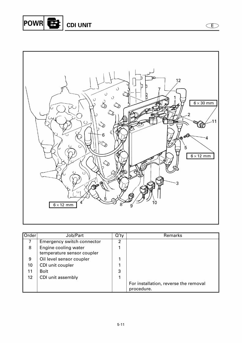
5-11
POWR
E
CDI UNIT
5
5
Order Job/Part Q’ty Remarks7 Emergency switch connector 28 Engine cooling water
temperature sensor coupler1
9 Oil level sensor coupler 110 CDI unit coupler 111 Bolt 312 CDI unit assembly 1
For installation, reverse the removal procedure.
5120

5-12
POWR
E
5
REMOVING/INSTALLING THE CDI UNIT 5
Order Job/Part Q’ty Remarks1 Ignition coil connector 62 Bolt 63 Ground lead 64 Ignition coil 65 Screw 46 Ground lead 17 CDI unit 1
Continued on next page.
5130
CDI UNIT

5-13
POWR
E
CDI UNIT
5
5
Order Job/Part Q’ty Remarks8 Emergency switch cap 19 Emergency switch 110 Collar 311 Grommet 312 CDI unit case 1
For installation, reverse the removal procedure.
5130

5-14
POWR
E
RECTIFIER/REGULATOR
RECTIFIER/REGULATOR 5
REMOVING/INSTALLING THE RECTIFIER/REGULATOR 5
Order Job/Part Q’ty RemarksNegative battery lead Refer to “POWER UNIT” on page 5-4.Positive battery lead Refer to “POWER UNIT” on page 5-4.Lighting coil coupler Refer to “STATOR ASSEMBLY” on
page 5-8.1 Bolt 12 Ground lead 23 Bolt 24 Rectifier/regulator cover 15 Collar 2
Continued on next page.
5140

5-15
POWR
E
RECTIFIER/REGULATOR
5
5
Å
Pre-mix models (except for 225DET)
Order Job/Part Q’ty Remarks6 Accessory lead 17 Rectifier/regulator coupler 18 Rectifier/regulator lead 3 Pre-mix models (except for 225DET)9 Lighting coil lead 2 Pre-mix models (except for 225DET)10 Rectifier/regulator 111 Bolt 212 Spacer 213 Battery lead terminal 1
For installation, reverse the removal procedure.
5140

5-16
POWR
E
RELAY ASSEMBLY AND STARTER MOTOR 5
REMOVING/INSTALLING THE RELAY ASSEMBLY AND STARTER MOTOR 5
Order Job/Part Q’ty RemarksPower trim and tilt leads Refer to “POWER UNIT” on page 5-4.Oil tank Refer to “OIL TANK” on page 4-10.
1 Plastic locking tie 12 Plastic tube 13 Starter motor lead 14 Positive battery lead 15 Relay assembly lead 36 Bolt 2
Continued on next page.
5150
RELAY ASSEMBLY AND STARTER MOTOR

5-17
POWR
E
RELAY ASSEMBLY AND STARTER MOTOR
5
5
Order Job/Part Q’ty Remarks7 Relay assembly 18 Bolt 19 Negative battery lead 110 Bolt 311 Starter motor 1
For installation, reverse the removal procedure.
5150

5-18
POWR
E
CONTROL UNIT 5
REMOVING/INSTALLING THE CONTROL UNIT 5
Order Job/Part Q’ty Remarks1 Throttle cam control link 22 Bolt 13 Accelerator control lever
assembly1
4 Nylon washer 15 Washer 16 Spacer 17 Spacer 18 Bushing 1
Continued on next page.
5160
CONTROL UNIT

5-19
POWR ECONTROL UNIT
55
Order Job/Part Q’ty Remarks9 Throttle lever 110 Spring 111 Bushing 112 Accelerator control lever 113 Bolt 114 Collar 115 Wave washer 116 Throttle cam 1
For installation, reverse the removal procedure.
5160

5-20
POWR E
INSTALLING THE CONTROL UNIT 5
1. Install:• Bushing 1 • Spring 2
NOTE:
Mesh the spring hook with the slit in theaccelerator control lever.
5165
2. Install:• Throttle lever 1
NOTE:
• Mesh the throttle lever hook with thespring hook.
• Turn the throttle lever clockwise and hookthe projection a on the throttle lever withthe notch b in the accelerator controllever.
5166
5167
3. Adjust:• Ignition timing
Refer to “CONTROL SYSTEM” onpage 3-3.
CONTROL UNIT

5-21
POWR EINTAKE MANIFOLD
INTAKE MANIFOLD 5REMOVING/INSTALLING THE INTAKE MANIFOLD (FOR 150G, 175F, S200F, 200G,
225D/P150TR, P175TR, S200TR, P200TR MODELS) 5
Order Job/Part Q’ty RemarksCarburetor assembly Refer to “CARBURETOR” on page 4-12.Fuel pump Refer to “FUEL PUMP” on page 4-6.
1 Screw 12 Timing plate 13 Bolt 24 Fuel enrichment valve 15 Intake manifold air vent hose 16 Oil hose 6
Continued on next page.
5170

5-22
POWR EINTAKE MANIFOLD
5
5
Order Job/Part Q’ty Remarks7 Recirculation hose 68 Bolt 169 Intake manifold 110 Gasket 111 Reed valve plate 112 Gasket 1
For installation, reverse the removal procedure.
5170
Not reusable
Not reusable

5-23
POWR E
5REMOVING/INSTALLING THE INATAKE MANIFOLD (EXCEPT FOR 150G, 175F,
S200F, 200G, 225D/P150TR, P175TR, S200TR, P200TR MODELS) 5
Order Job/Part Q’ty RemarksCarburetor assembly Refer to “CARBURETOR” on page 4-12.Fuel pump Refer to “FUEL PUMP” on page 4-6.
1 Screw 12 Timing plate 13 Bolt 24 Fuel enrichment valve 15 Intake manifold air vent hose 1
Continued on next page.
5180
INTAKE MANIFOLD

5-24
POWR EINTAKE MANIFOLD
5
5
Order Job/Part Q’ty Remarks6 Oil hose 67 Recirculation hose 128 Bolt 169 Intake manifold 110 Gasket 1
For installation, reverse the removal procedure.
5180
Not reusable

5-25
POWR EREED VALVES
REED VALVES 5REMOVING/INSTALLING THE REED VALVES 5
Å For 150G, 175F, S200F, 200G, 225D/P150TR, P175TR, S200TR, P200TR modelsı Except for 150G, 175F, S200F, 200G, 225D/P150TR, P175TR, S200TR, P200TR models
Order Job/Part Q’ty RemarksIntake manifold Refer to “INTAKE MANIFOLD” on
page 5-21.1 Screw 122 Reed valve assembly 63 Gasket 64 Screw 8 (4) (Pre-mix 150 models)5 Reed valve stopper 4 (2) (Pre-mix 150 models)6 Reed valve 4 (2) (Pre-mix 150 models)7 Reed valve seat 1
For installation, reverse the removal procedure.
5190
Not reusable

5-26
POWR
E
REED VALVES
INSPECTING THE REED VALVE
ASSEMBLY 5
1. Inspect:• Reed valve
Cracks/damage
→
Replace.
2. Measure:• Warpage limit
a
Out of specification
→
Replace.
Warpage limit0.2 mm (0.008 in)
5220
3. Measure:• Reed valve stopper height
a
Out of specification
→
Replace.
Reed valve stopper height6.5
±
0.3 mm (0.26
±
0.01 in)
5230

5-27
POWR
E
CYLINDER HEADS
CYLINDER HEADS 5
REMOVING/INSTALLING THE CYLINDER HEADS 5
Order Job/Part Q’ty RemarksSpark plug cap Refer to “CDI UNIT” on page 5-10.
1 Spark plug 62 Bolt 83 Thermostat cover 24 Gasket 25 Thermostat 26 Bolt 367 Clamp 1 (starboard side)8 Cylinder head cover 2
Continued on next page.
5250
Not reusable

5-28
POWR
E
5
5
Order Job/Part Q’ty Remarks9 Gasket 210 Thermo switch 211 Engine cooling water
temperature sensor1
12 Bolt 213 Ground lead 214 Bolt 2815 Cylinder head 216 Gasket 2
For installation, reverse the removal procedure.
5250
Not reusable
Not reusable
CYLINDER HEADS

5-29
POWR
E
CYLINDER HEADS
INSPECTING THE THERMOSTATS 5
1. Inspect:• Thermostat
Damage/valve does not open
→
Replace.2. Measure:
• Thermostat opening temperature• Valve lift
a
Out of specification
→
Replace.
Measuring steps
(1) Suspend the thermostat in a containerfilled with water.
(2) Place a thermometer in the water.(3) Slowly heat the water.(4) While stirring the water, check that the
thermostat opens at the specified tem-perature.
Water temperature Valve lift
Below 48 - 52 ˚C
(118 - 126 ˚F)
0 mm
(0 in)
Above 60 ˚C
(140 ˚F)
Min. 3 mm
(0.12 in)
5260
INSPECTING THE CYLINDER HEADS 5
1. Inspect:• Combustion chamber
Carbon deposits
→
Clean.• Water jacket
Mineral deposits/rust
→
Clean.
CAUTION:
Do not scratch the contacting surfaces of
the cylinder head and cylinder head cover.
5265

5-30
POWR
E
2. Measure:• Cylinder head warpage
(with a straightedge and thicknessgauge)Out of specification
→
Resurface orreplace.
Resurfacing steps
(1) Place a 400 - 600 grit wet sandpaper onthe surface plate.
(2) Resurface the cylinder head by movingit in a figure-eight motion along thesandpaper.
NOTE:
Rotate the cylinder head several times to
ensure an even surface.
Warpage limit0.1 mm (0.004 in)5270
5280
5290
CYLINDER HEADS

5-31
POWR
E
EXHAUST COVERS
EXHAUST COVERS 5
REMOVING/INSTALLING THE EXHAUST COVERS 5
Order Job/Part Q’ty RemarksPilot water hose Refer to “POWER UNIT” on page 5-4.Cooling water hose Refer to “POWER UNIT” on page 5-4.CDI unit assembly Refer to “CDI UNIT” on page 5-10.
1 Bolt 22 Pressure control valve cover 13 Gasket 14 Spring 15 Pressure control valve 16 Pressure control valve seat 1
Continued on next page.
5300
Not reusable

5-32
POWR
E
EXHAUST COVERS
5
5
Order Job/Part Q’ty Remarks7 Bolt 18 Lead holder 19 Bolt 2910 Lead holder 211 Exhaust outer cover 112 Gasket 113 Exhaust inner cover 114 Gasket 1
For installation, reverse the removal procedure.
5300
Not reusable
Not reusable

5-33
POWR
E
EXHAUST COVERS
INSPECTING THE PRESSURE
CONTROL VALVE 5
Inspect:• Pressure control valve seat
1
• Pressure control valve
2
• Pressure control valve cover
3
Cracks/damage
→
Replace any defec-tive parts.
• Spring
4
Damage/wear
→
Replace.
5310

5-34
POWR
E
CRANKCASE
CRANKCASE 5
REMOVING/INSTALLING THE CRANKCASE 5
Order Job/Part Q’ty RemarksFlywheel magnet assembly Refer to “FLYWHEEL MAGNET
ASSEMBLY” on page 5-1.Power unit Refer to “POWER UNIT” on page 5-4.Pulser coil bushing Refer to “STATOR ASSEMBLY” on
page 5-8.Intake manifold Refer to “INTAKE MANIFOLD” on
page 5-21.1 Bolt 122 Bolt 83 Bolt 3
Continued on next page.
5320

5-35
POWR
E
5
5
Å
For 150G, 175F, S200F, 200G, 225D/P150TR, P175TR, S200TR, P200TR models
ı
Except for 150G, 175F, S200F, 200G, 225D/P150TR, P175TR, S200TR, P200TR models
Order Job/Part Q’ty Remarks4 Bolt 45 Crankcase 16 Oil seal housing 17 O-ring 18 Oil seal 29 Dowel pin 2
For installation, reverse the removal procedure.
5320
CRANKCASE

5-36
POWR
E
CRANKCASE
ASSEMBLING THE OIL SEAL
HOUSING 5
Install:• Oil seal
Å
For USA and Canada
ı
Except for USA and Canada
Bearing/oil seal attachment ....
1
YB-06195 / 90890-06637
90890-06631Driver rod ..................................
2
YB-06071 / 90890-06606
Å
5330
ı
5340
INSTALLING THE CRANKCASE 5
Apply:• Gasket Maker
(onto the crankcase mating surfaces)
NOTE:
• Clean the mating surfaces of the crank-case and cylinder body before applyingGasket Maker
.• Do not allow any sealant to overflow from
the mating surfaces.
5350

5-37
POWR
E
CYLINDER BODY ASSEMBLY
CYLINDER BODY ASSEMBLY 5
DISASSEMBLING/ASSEMBLING THE CYLINDER BODY ASSEMBLY 5
Order Job/Part Q’ty RemarksCylinder heads Refer to “CYLINDER HEADS” on
page 5-27.Crankcase Refer to “CRANKCASE” on page 5-34.
1 Upper bearing housing 12 Oil seal 13 O-ring 24 Needle bearing 15 Connecting rod bolt 126 Connecting rod cap 67 Big-end bearing 6
Continued on next page.
5360

5-38
POWR ECYLINDER BODY ASSEMBLY
55
Order Job/Part Q’ty Remarks8 Piston/connecting rod assembly 69 Crankshaft assembly 110 Clip 211 Main journal bearing 212 Screw 813 Anode 814 Bolt 715 Lead holder 116 Cylinder cover 1
Continued on next page.
5360

5-39
POWR E
55
Order Job/Part Q’ty Remarks17 Gasket 118 Bolt 219 Engine hanger 120 Bolt 421 Damper bracket 222 Oil pump driven gear 1 Oil injection models23 Cylinder body 1
For assembly, reverse the disassembly procedure.
5360
Not reusable
CYLINDER BODY ASSEMBLY

5-40
POWR ECYLINDER BODY ASSEMBLY
5DISASSEMBLING/ASSEMBLING THE PISTON AND CONNECTING ROD
ASSEMBLIES 5
Order Job/Part Q’ty Remarks1 Piston pin clip 122 Piston pin 63 Piston 64 Washer 125 Small-end bearing 66 Piston ring 127 Connecting rod 6
For assembly, reverse the disassembly procedure.
5370
Not reusable

5-41
POWR ECYLINDER BODY ASSEMBLY
5DISASSEMBLING/ASSEMBLING THE CRANKSHAFT ASSEMBLY 5
Order Job/Part Q’ty Remarks1 Labyrinth ring 92 Circlip 13 Ball bearing 14 Oil pump drive gear 1 Oil injection models5 Crankshaft 1
For assembly, reverse the disassembly procedure.
5600

5-42
POWR ECYLINDER BODY ASSEMBLY
DISASSEMBLING THE UPPER
BEARING HOUSING 5
Remove:• Needle bearing
Å For USA and Canadaı Except for USA and Canada
Needle bearing attachment..... 1 YB-06205 / 90890-06663
Driver rod .................................. 2 90890-06606
Å
5390
ı
5400
REMOVING THE BEARING AND OIL
PUMP DRIVE GEAR 5
Remove:• Bearing• Oil pump drive gear
Bearing separator ..................... 1 YB-06219 / 90890-06534
Guide plate stand ..................... 2 90890-06538
Guide plate................................ 3 90890-06501
Bearing puller............................ 4 90890-06535
5610
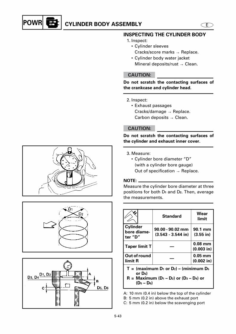
5-43
POWR ECYLINDER BODY ASSEMBLY
INSPECTING THE CYLINDER BODY 5
1. Inspect:• Cylinder sleeves
Cracks/score marks → Replace.• Cylinder body water jacket
Mineral deposits/rust → Clean.
CAUTION:
Do not scratch the contacting surfaces of
the crankcase and cylinder head.
2. Inspect:• Exhaust passages
Cracks/damage → Replace.Carbon deposits → Clean.
CAUTION:
Do not scratch the contacting surfaces of
the cylinder and exhaust inner cover.
3. Measure:• Cylinder bore diameter “D”
(with a cylinder bore gauge)Out of specification → Replace.
NOTE:
Measure the cylinder bore diameter at threepositions for both D1 and D2. Then, averagethe measurements.
A: 10 mm (0.4 in) below the top of the cylinder B: 5 mm (0.2 in) above the exhaust portC: 5 mm (0.2 in) below the scavenging port
StandardWear
limit
Cylinder
bore diame-
ter “D”
90.00 - 90.02 mm
(3.543 - 3.544 in)
90.1 mm
(3.55 in)
Taper limit T —0.08 mm
(0.003 in)
Out of round
limit R—
0.05 mm
(0.002 in)
T = (maximum D1 or D2) – (minimum D5 or D6)
R = Maximum (D1 – D2) or (D3 – D4) or (D5 – D6)
5410
5420
5430

5-44
POWR ECYLINDER BODY ASSEMBLY
INSPECTING THE PISTONS 5
Measure:• Piston diameter
(with a micrometer)Out of specification → Replace.
*: Except for USA
NOTE:
When measuring the piston diameter, posi-tion the micrometer in relation to the pistonpin hole as shown.
Measuring
point “H”Piston diameter
Standard10 mm
(0.4 in)
89.895 - 89.915 mm
(3.5392 - 3.5400 in)
Oversize piston diameter1st oversize*
90.15 mm (3.549 in)2nd oversize
90.40 mm (3.559 in)
5440
CALCULATING THE PISTON-TO-
CYLINDER CLEARANCE 5
Calculate:• Piston-to-cylinder clearance a
Out of specification → Replace the pis-ton and piston rings, the cylinder orboth.
Piston-to-cylinder
clearance=
Cylinder bore
diameter– Piston
diameter
Piston-to-cylinder clearance0.100 - 0.106 mm(0.0039 - 0.0042 in)
5450

5-45
POWR ECYLINDER BODY ASSEMBLY
INSPECTING THE PISTON PINS AND
SMALL-END BEARINGS 5
1. Inspect:• Piston pin• Small-end bearing
Heat discoloration → Replace.Damage/scratches → Replace.
2. Measure:• Piston pin diameter
(with a micrometer)Out of specification → Replace.
Piston pin diameter23.065 - 23.070 mm(0.9081 - 0.9083 in)
5460
3. Measure:• Piston pin boss diameter
(with a micrometer)Out of specification → Replace.
Piston pin boss diameter23.074 - 23.085 mm(0.9084 - 0.9089 in)
5470
INSPECTING THE PISTON RINGS 5
NOTE:
• Before inspecting the piston rings, be sureto inspect the cylinder body.
• Piston rings should always be replaced asa set (per piston).

5-46
POWR ECYLINDER BODY ASSEMBLY
1. Measure:• Piston ring end gap a
(with a thickness gauge)Out of specification → Replace.
NOTE:
Push the piston ring into the cylinder withthe piston crown.
Piston ring end gap0.30 - 0.40 mm (0.012 - 0.016 in)
Piston ring end gap limit0.60 mm (0.024 in)
Measuring point “H”20 mm (0.8 in)
5480
5490
2. Measure:• Piston ring side clearance b
(with a thickness gauge)Out of specification → Replace the pis-ton and piston rings as a set.
NOTE:
When measuring the piston ring side clear-ance, the outside of the piston ring shouldbe flush with the piston wall.
Piston ring side clearance0.02 - 0.06 mm (0.001 - 0.002 in)
5500
INSPECTING THE OIL PUMP DRIVEN
GEAR 5
Inspect:• Oil pump driven gear
Cracks/pitting/wear → Replace.
5510

5-47
POWR ECYLINDER BODY ASSEMBLY
INSPECTING THE LABYRINTH RINGS5
1. Inspect:• Labyrinth ring 1
Cracks/damage/wear → Replace.2. Measure:
• Labyrinth ring wear a or b + cOut of specification → Replace.
INSPECTING THE CRANKSHAFT 5
1. Measure:• Crankshaft runout
(with V-blocks and a dial gauge)Out of specification → Replace.
Labyrinth ring wear limit0.10 mm (0.004 in)
Runout limit0.05 mm (0.002 in)
5620
5630
2. Measure:• Small-end axial play
Out of specification → Replace theconnecting rod.
Small-end axial play limit2.0 mm (0.08 in)
5640
3. Measure:• Big-end side clearance
Out of specification → Replace theconnecting rod.
Big-end side clearance0.12 - 0.26 mm (0.005 - 0.010 in)
5650
4. Inspect:• Crankshaft bearing
Pitting/rumbling → Replace.5. Inspect:
• Oil pump drive gearCracks/pitting/wear → Replace.

5-48
POWR ECYLINDER BODY ASSEMBLY
INSTALLING THE OIL PUMP DRIVE
GEAR 5
Install:• Oil pump drive gear
Bearing separator ..................... 1 YB-06219 / 90890-06534
Bearing/oil seal attachment .... 2 90890-0666190890-066225660
INSTALLING THE BEARING 5
Install:• Bearing
Bearing separator ..................... 1 YB-06219 / 90890-06534
Bearing/oil seal attachment .... 2 90890-0666290890-06622
5670
INSTALLING THE PISTON RINGS AND
PISTON 5
1. Install:• 2nd piston ring• Top piston ring
CAUTION:
• Align each piston ring end gap with its
respective locating pin.
• After installing the piston rings, check
that they move smoothly.
5520

5-49
POWR ECYLINDER BODY ASSEMBLY
2. Install:• Small-end bearing 1 • Washers 2 • Piston 3 • Piston pin 4 • Piston pin clips 5
CAUTION:
The washers must be installed with their
convex sides facing towards the piston.
NOTE:
The embossed YAMAHA mark a on theconnecting rod must face the same direc-tion as the “UP” mark on the piston.
5530
ASSEMBLING THE UPPER BEARING
HOUSING 5
1. Install:• Needle bearing
Å For USA and Canadaı Except for USA and Canada
Needle bearing attachment..... 1 YB-06205 / 90890-06663
Driver rod .................................. 2 90890-06606
Å
5540
ı
5550
2. Install:• Oil seal
Bearing/oil seal attachment .... 1 YB-06195 / 90890-06624
Driver rod .................................. 2 YB-06071 / 90890-06606
5560

5-50
POWR ECYLINDER BODY ASSEMBLY
INSTALLING THE CRANKSHAFT
ASSEMBLY 5
Install:• Cylinder body• Crankshaft assembly
NOTE:
• Align the crankshaft labyrinth ring endgaps with their respective locating pins.
• Install the bearing locating pins into thecylinder body.
5570
INSTALLING THE PISTON AND
CONNECTING ROD ASSEMBLIES 5
Install:• Piston and connecting rod assembly
NOTE:
• Before installing the piston and connect-ing rod assemblies, lubricate the cylinderwalls with 2-stroke outboard engine oil.
• Reinstall the piston and connecting rodassemblies in their original cylinders.
• Install the piston and connecting rodassemblies with the “S” mark in the star-board side cylinders, and those with the“P” mark in the port side cylinders.
• The “UP” mark on the piston crown mustface towards the flywheel.
Piston ring compressorYU-33294 / 90890-06530
5580
5590

ELOWR
CHAPTER 6
LOWER UNIT
LOWER UNIT (REGULAR ROTATION MODELS)
......................................... 6-1REMOVING/INSTALLING THE LOWER UNIT ........................................ 6-1REMOVING THE PROPELLER ................................................................. 6-3INSPECTING THE PROPELLER ............................................................... 6-3INSTALLING THE PROPELLER................................................................ 6-3
WATER PUMP (REGULAR ROTATION MODELS)
........................................ 6-4REMOVING/INSTALLING THE WATER PUMP....................................... 6-4INSPECTING THE IMPELLER HOUSING ................................................ 6-6INSPECTING THE IMPELLER AND IMPELLER HOUSING CUP ............ 6-6INSPECTING THE WOODRUFF KEY....................................................... 6-6INSTALLING THE IMPELLER AND IMPELLER HOUSING..................... 6-6
SHIFT ROD ASSEMBLY (REGULAR ROTATION MODELS)
........................ 6-7REMOVING/INSTALLING THE SHIFT ROD ASSEMBLY ....................... 6-7REMOVING THE SHIFT ROD ASSEMBLY.............................................. 6-8
PROPELLER SHAFT HOUSING ASSEMBLY
(REGULAR ROTATION MODELS)
................................................................ 6-9REMOVING/INSTALLING THE PROPELLER SHAFT HOUSING ASSEMBLY.............................................................................................. 6-9DISASSEMBLING/ASSEMBLING THE PROPELLER SHAFT HOUSING .............................................................................................. 6-11DISASSEMBLING/ASSEMBLING THE PROPELLER SHAFT ASSEMBLY............................................................................................ 6-12REMOVING THE PROPELLER SHAFT HOUSING ASSEMBLY............ 6-13DISASSEMBLING THE PROPELLER SHAFT HOUSING ...................... 6-13INSPECTING THE REVERSE GEAR....................................................... 6-14INSPECTING THE BEARING.................................................................. 6-14INSPECTING THE PROPELLER SHAFT HOUSING .............................. 6-14INSPECTING THE DOG CLUTCH .......................................................... 6-15INSPECTING THE PROPELLER SHAFT................................................. 6-15ASSEMBLING THE PROPELLER SHAFT HOUSING ............................ 6-15INSTALLING THE PROPELLER SHAFT HOUSING ASSEMBLY.......... 6-16

E
1 2 3 4 5 6 7 8 9
LOWR
DRIVE SHAFT (REGULAR ROTATION MODELS)
....................................... 6-17REMOVING/INSTALLING THE DRIVE SHAFT...................................... 6-17REMOVING THE DRIVE SHAFT ............................................................ 6-19DISASSEMBLING THE DRIVE SHAFT HOUSING ASSEMBLY ........... 6-19DISASSEMBLING THE FORWARD GEAR ASSEMBLY ....................... 6-19INSPECTING THE PINION ..................................................................... 6-20INSPECTING THE DRIVE SHAFT .......................................................... 6-20INSPECTING THE DRIVE SHAFT HOUSING ........................................ 6-20INSPECTING THE BEARINGS ............................................................... 6-20ASSEMBLING THE FORWARD GEAR ASSEMBLY ............................. 6-20ASSEMBLING THE DRIVE SHAFT HOUSING ASSEMBLY ................. 6-21INSTALLING THE DRIVE SHAFT........................................................... 6-22
LOWER CASE ASSEMBLY (REGULAR ROTATION MODELS)
.................. 6-23DISASSEMBLING/ASSEMBLING THE LOWER CASE ASSEMBLY............................................................................................ 6-23DISASSEMBLING THE LOWER CASE ASSEMBLY ............................. 6-24INSPECTING THE DRIVE SHAFT SLEEVE............................................ 6-24INSPECTING THE NEEDLE BEARING................................................... 6-24ASSEMBLING THE LOWER CASE ASSEMBLY ................................... 6-24
LOWER UNIT (COUNTER ROTATION MODELS)
....................................... 6-25REMOVING/INSTALLING THE LOWER UNIT ...................................... 6-25REMOVING THE PROPELLER ............................................................... 6-27INSPECTING THE PROPELLER ............................................................. 6-27INSTALLING THE PROPELLER.............................................................. 6-27
WATER PUMP (COUNTER ROTATION MODELS)
..................................... 6-28REMOVING/INSTALLING THE WATER PUMP..................................... 6-28INSPECTING THE IMPELLER HOUSING .............................................. 6-30INSPECTING THE IMPELLER AND IMPELLER HOUSING CUP .......... 6-30INSPECTING THE WOODRUFF KEY..................................................... 6-30INSTALLING THE IMPELLER AND IMPELLER HOUSING................... 6-30
SHIFT ROD ASSEMBLY (COUNTER ROTATION MODELS)
...................... 6-31REMOVING/INSTALLING THE SHIFT ROD ASSEMBLY ..................... 6-31REMOVING THE SHIFT ROD ASSEMBLY............................................ 6-32

ELOWR
PROPELLER SHAFT HOUSING ASSEMBLY
(COUNTER ROTATION MODELS)
.............................................................. 6-33REMOVING/INSTALLING THE PROPELLER SHAFT HOUSING ASSEMBLY............................................................................................ 6-33DISASSEMBLING/ASSEMBLING THE PROPELLER SHAFT HOUSING ASSEMBLY.......................................................................... 6-34DISASSEMBLING/ASSEMBLING THE PROPELLER SHAFT ASSEMBLY............................................................................................ 6-36REMOVING THE PROPELLER SHAFT HOUSING ASSEMBLY............ 6-37REMOVING THE PROPELLER SHAFT ASSEMBLY.............................. 6-37DISASSEMBLING THE PROPELLER SHAFT HOUSING ASSEMBLY . 6-38DISASSEMBLING THE FORWARD GEAR ASSEMBLY ....................... 6-38INSPECTING THE FORWARD GEAR .................................................... 6-38INSPECTING THE BEARING.................................................................. 6-38INSPECTING THE PROPELLER SHAFT HOUSING .............................. 6-38INSPECTING THE DOG CLUTCH .......................................................... 6-39INSPECTING THE PROPELLER SHAFT................................................. 6-39ASSEMBLING THE PROPELLER SHAFT HOUSING ............................ 6-39INSTALLING THE PROPELLER SHAFT ASSEMBLY............................ 6-40INSTALLING THE PROPELLER SHAFT HOUSING ASSEMBLY.......... 6-40
DRIVE SHAFT (COUNTER ROTATION MODELS)
...................................... 6-41REMOVING/INSTALLING THE DRIVE SHAFT...................................... 6-41REMOVING THE DRIVE SHAFT ............................................................ 6-43REMOVING THE REVERSE GEAR......................................................... 6-43DISASSEMBLING THE DRIVE SHAFT HOUSING ASSEMBLY ........... 6-43DISASSEMBLING THE REVERSE GEAR ASSEMBLY.......................... 6-43INSPECTING THE PINION ..................................................................... 6-44INSPECTING THE DRIVE SHAFT .......................................................... 6-44INSPECTING THE DRIVE SHAFT HOUSING ........................................ 6-44INSPECTING THE BEARINGS ............................................................... 6-44ASSEMBLING THE REVERSE GEAR ASSEMBLY................................ 6-45ASSEMBLING THE DRIVE SHAFT HOUSING ASSEMBLY ................. 6-45INSTALLING THE REVERSE GEAR....................................................... 6-46INSTALLING THE DRIVE SHAFT........................................................... 6-46
LOWER CASE ASSEMBLY (COUNTER ROTATION MODELS)
................. 6-47DISASSEMBLING/ASSEMBLING THE LOWER CASE ASSEMBLY............................................................................................ 6-47DISASSEMBLING THE LOWER CASE ASSEMBLY ............................. 6-48INSPECTING THE DRIVE SHAFT SLEEVE............................................ 6-48INSPECTING THE NEEDLE BEARING................................................... 6-48ASSEMBLING THE LOWER CASE ASSEMBLY ................................... 6-48
ELOWR
LOWER UNIT (DUAL PROPELLER MODELS)
............................................. 6-49REMOVING/INSTALLING THE LOWER UNIT ...................................... 6-49REMOVING THE PROPELLERS............................................................. 6-51INSPECTING THE PROPELLERS........................................................... 6-51INSTALLING THE PROPELLERS ........................................................... 6-52
WATER PUMP (DUAL PROPELLER MODELS)
........................................... 6-53REMOVING/INSTALLING THE WATER PUMP..................................... 6-53INSPECTING THE IMPELLER HOUSING .............................................. 6-55INSPECTING THE IMPELLER AND IMPELLER HOUSING CUP .......... 6-55INSPECTING THE WOODRUFF KEY..................................................... 6-55INSTALLING THE IMPELLER AND IMPELLER HOUSING................... 6-55
SHIFT ROD (DUAL PROPELLER MODELS)
................................................. 6-56REMOVING/INSTALLING THE SHIFT ROD .......................................... 6-56REMOVING THE SHIFT ROD................................................................. 6-57
PROPELLER SHAFT HOUSING ASSEMBLY
(DUAL PROPELLER MODELS)
.................................................................... 6-58REMOVING/INSTALLING THE PROPELLER SHAFT HOUSING ASSEMBLY............................................................................................ 6-58DISASSEMBLING/ASSEMBLING THE PROPELLER SHAFT HOUSING ASSEMBLY.......................................................................... 6-59REMOVING THE PROPELLER SHAFT HOUSING ASSEMBLY............ 6-61REMOVING THE OUTER PROPELLER SHAFT ..................................... 6-61DISASSEMBLING THE PROPELLER SHAFT HOUSING ASSEMBLY............................................................................................ 6-61DISASSEMBLING THE OUTER PROPELLER SHAFT ASSEMBLY ...... 6-62REMOVING THE REAR GEAR ASSEMBLY .......................................... 6-62INSPECTING THE BEARINGS ............................................................... 6-62INSPECTING THE PROPELLER SHAFT HOUSING .............................. 6-62INSPECTING THE OUTER PROPELLER SHAFT ................................... 6-62INSPECTING THE REAR GEAR ............................................................. 6-62ASSEMBLING THE OUTER PROPELLER SHAFT ASSEMBLY ............ 6-63ASSEMBLING THE PROPELLER SHAFT HOUSING ASSEMBLY ....... 6-63INSTALLING THE PROPELLER SHAFT HOUSING ASSEMBLY.......... 6-65
DRIVE SHAFT (DUAL PROPELLER MODELS)
............................................ 6-66REMOVING/INSTALLING THE DRIVE SHAFT...................................... 6-66REMOVING THE DRIVE SHAFT ............................................................ 6-68INSPECTING THE PINION ..................................................................... 6-68INSPECTING THE DRIVE SHAFT .......................................................... 6-68INSTALLING THE DRIVE SHAFT........................................................... 6-68DISASSEMBLING THE DRIVE SHAFT HOUSING ASSEMBLY ........... 6-69INSPECTING THE DRIVE SHAFT HOUSING ........................................ 6-69ASSEMBLING THE DRIVE SHAFT HOUSING ASSEMBLY ................. 6-69

ELOWR
INNER PROPELLER SHAFT ASSEMBLY (DUAL PROPELLER MODELS)
.. 6-70DISASSEMBLING/ASSEMBLING THE INNER PROPELLER SHAFT ASSEMBLY............................................................................................ 6-70REMOVING THE SPRING ...................................................................... 6-72DISASSEMBLING THE FRONT GEAR ASSEMBLY.............................. 6-72INSPECTING THE DOG CLUTCHES...................................................... 6-72INSPECTING THE INNER PROPELLER SHAFT .................................... 6-72INSPECTING THE BEARING.................................................................. 6-72INSPECTING THE FRONT GEAR........................................................... 6-72ASSEMBLING THE FRONT GEAR ASSEMBLY.................................... 6-73INSTALLING THE SPRING .................................................................... 6-73
LOWER CASE ASSEMBLY (DUAL PROPELLER MODELS)
....................... 6-74DISASSEMBLING/ASSEMBLING THE LOWER CASE ASSEMBLY............................................................................................ 6-74DISASSEMBLING THE LOWER CASE ASSEMBLY ............................. 6-75INSPECTING THE DRIVE SHAFT SLEEVE............................................ 6-75INSPECTING THE NEEDLE BEARING................................................... 6-75ASSEMBLING THE LOWER CASE ASSEMBLY ................................... 6-75
SHIMMING (REGULAR ROTATION MODELS)
........................................... 6-77
SHIMMING (REGULAR ROTATION MODELS)
(FOR USA AND CANADA)
.......................................................................... 6-78SELECTING THE PINION SHIMS .......................................................... 6-78SELECTING THE FORWARD GEAR SHIMS ......................................... 6-80SELECTING THE REVERSE GEAR SHIMS............................................ 6-82
SHIMMING (REGULAR ROTATION MODELS)
(EXCEPT FOR USA AND CANADA)
........................................................... 6-84SELECTING THE PINION SHIMS .......................................................... 6-84SELECTING THE FORWARD GEAR SHIMS ......................................... 6-86SELECTING THE REVERSE GEAR SHIM.............................................. 6-87
BACKLASH (REGULAR ROTATION MODELS)
........................................... 6-89MEASURING THE FORWARD GEAR BACKLASH ............................... 6-89MEASURING THE REVERSE GEAR BACKLASH.................................. 6-91
SHIMMING (COUNTER ROTATION MODELS)
.......................................... 6-94
SHIMMING (COUNTER ROTATION MODELS)
(FOR USA AND CANADA)
.......................................................................... 6-95SELECTING THE PINION SHIMS .......................................................... 6-95SELECTING THE REVERSE GEAR SHIMS............................................ 6-97SELECTING THE FORWARD GEAR SHIMS ......................................... 6-98SELECTING THE PROPELLER SHAFT SHIMS.................................... 6-100

ELOWR
SHIMMING (COUNTER ROTATION MODELS)
(EXCEPT FOR USA AND CANADA)
......................................................... 6-101SELECTING THE PINION SHIMS ........................................................ 6-101SELECTING THE REVERSE GEAR SHIMS.......................................... 6-103SELECTING THE FORWARD GEAR SHIMS ....................................... 6-104SELECTING THE PROPELLER SHAFT SHIMS.................................... 6-106
BACKLASH (COUNTER ROTATION MODELS)
........................................ 6-107MEASURING THE FORWARD GEAR BACKLASH ............................. 6-107MEASURING THE REVERSE GEAR BACKLASH................................ 6-108
SHIMMING (DUAL PROPELLER MODELS)
.............................................. 6-111SELECTING THE PINION SHIMS ........................................................ 6-112SELECTING THE FRONT GEAR SHIMS.............................................. 6-114SELECTING THE REAR GEAR SHIMS ................................................ 6-115SELECTING THE OUTER PROPELLER SHAFT SHIMS ...................... 6-117
BACKLASH (DUAL PROPELLER MODELS)
.............................................. 6-118MEASURING THE FRONT GEAR BACKLASH.................................... 6-118MEASURING THE REAR GEAR BACKLASH ...................................... 6-120

6-1
ELOWR
LOWER UNIT (REGULAR ROTATION MODELS)
LOWER UNIT (REGULAR ROTATION MODELS) 6
REMOVING/INSTALLING THE LOWER UNIT
Order Job/Part Q’ty Remarks1 Speedometer hose 12 Cotter pin 13 Propeller nut 14 Washer 15 Washer 16 Propeller 17 Spacer 1
Continued on next page.
6010

6-2
ELOWR
6
Order Job/Part Q’ty Remarks8 Bolt 19 Trim tab 110 Bolt 1 (with washer)11 Bolt 6 (with washer)12 Lower unit 113 Dowel pin 2
For installation, reverse the removal procedure.
6010
LOWER UNIT (REGULAR ROTATION MODELS)

6-3
ELOWR
LOWER UNIT (REGULAR ROTATION MODELS)
REMOVING THE PROPELLER
Remove:• Propeller
WARNING
Do not hold the propeller with your hands
when removing or installing it. Be sure to
remove the battery leads from the batteries
and the lanyard engine stop switch. Put a
block of wood between the cavitation plate
and propeller to keep the propeller from
turning.
6016
INSPECTING THE PROPELLER
Inspect:• Blades• Splines
Cracks/damage/wear
→
Replace.
INSTALLING THE PROPELLER
Install:• Propeller
WARNING
Do not hold the propeller with your hands
when removing or installing it. Be sure to
remove the battery leads from the batteries
and the lanyard engine stop switch. Put a
block of wood between the cavitation plate
and propeller to keep the propeller from
turning.
NOTE:
If the groove in the propeller nut is notaligned with the cotter pin hole, tighten the
nut further until they are aligned.
6017

6-4
ELOWR
WATER PUMP (REGULAR ROTATION MODELS)
WATER PUMP (REGULAR ROTATION MODELS) 6
REMOVING/INSTALLING THE WATER PUMP
Order Job/Part Q’ty RemarksLower unit Refer to “LOWER UNIT (REGULAR
ROTATION MODELS)” on page 6-1.1 Bolt 42 Plate washer 43 Impeller housing 14 Impeller housing cup 15 Grommet 16 Spacer 17 Collar 1
Continued on next page.
6020

6-5
ELOWR
6
Order Job/Part Q’ty Remarks8 Spacer 19 Washer 210 Wave washer 111 Impeller 112 Woodruff key 113 Impeller plate 114 Gasket 115 Dowel pin 2
For installation, reverse the removal procedure.
6020
Not reusable
WATER PUMP (REGULAR ROTATION MODELS)

6-6
ELOWR
WATER PUMP (REGULAR ROTATION MODELS)
INSPECTING THE IMPELLER
HOUSING
Inspect:• Impeller housing
Cracks/damage
→
Replace.
INSPECTING THE IMPELLER AND
IMPELLER HOUSING CUP
Inspect:• Impeller• Impeller housing cup
Cracks/damage
→
Replace any defec-tive parts.
INSPECTING THE WOODRUFF KEY
Inspect:• Woodruff key
Damage/wear
→
Replace.
INSTALLING THE IMPELLER AND
IMPELLER HOUSING
1. Install:• Washers
1
• Wave washer
2
• Spacer
3
• Collar
4
NOTE:
• The collar and spacer should fit togetherfirmly.
• Install the collar with some appropriatetool
a
that fits over the drive shaft as
shown.
2. Install:• O-ring
1
• Impeller housing cup
2
• Impeller housing
3
• O-ring
4
NOTE:
• When installing the impeller housing cup,align its projection with the hole in theimpeller housing.
• When installing the water pump housing,
turn the drive shaft clockwise.
6025
6030

6-7
ELOWR
SHIFT ROD ASSEMBLY
(REGULAR ROTATION MODELS)
SHIFT ROD ASSEMBLY (REGULAR ROTATION MODELS) 6
REMOVING/INSTALLING THE SHIFT ROD ASSEMBLY
Order Job/Part Q’ty RemarksImpeller plate Refer to “WATER PUMP (REGULAR
ROTATION MODELS)” on page 6-4.1 Bolt 3 (with washer)2 Shift rod assembly 13 Shift rod 14 Spring 15 Oil seal housing 16 Oil seal 1
For installation, reverse the removal procedure.
6035

6-8
ELOWR
SHIFT ROD ASSEMBLY
(REGULAR ROTATION MODELS)
REMOVING THE SHIFT ROD
ASSEMBLY
Remove:• Shift rod assembly
NOTE:
Remove the shift rod assembly when the
shift rod is in the neutral position.

6-9
ELOWR
PROPELLER SHAFT HOUSING ASSEMBLY
(REGULAR ROTATION MODELS)
PROPELLER SHAFT HOUSING ASSEMBLY(REGULAR ROTATION MODELS) 6
REMOVING/INSTALLING THE PROPELLER SHAFT HOUSING ASSEMBLY
Order Job/Part Q’ty RemarksGear oil Refer to “CHANGING AND INSPECTING
THE GEAR OIL” on page 3-17.Shift rod assembly Refer to “SHIFT ROD ASSEMBLY
(REGULAR ROTATION MODELS)” on page 6-7.
1 Ring nut 12 Claw washer 13 Propeller shaft housing assembly 14 Straight key 1
Continued on next page.
6040

6-10
ELOWR
PROPELLER SHAFT HOUSING ASSEMBLY
(REGULAR ROTATION MODELS)
6
Order Job/Part Q’ty Remarks5 Reverse gear shim *6 Propeller shaft assembly 17 Washer 18 Propeller shaft housing 1
For installation, reverse the removal procedure.
*: As required
6040

6-11
ELOWR
6
DISASSEMBLING/ASSEMBLING THE PROPELLER SHAFT HOUSING
Order Job/Part Q’ty Remarks1 O-ring 12 Reverse gear 13 Thrust washer 14 Ball bearing 15 Oil seal 26 Needle bearing 17 Propeller shaft housing 1
For assembly, reverse the disassembly procedure.
6045
PROPELLER SHAFT HOUSING ASSEMBLY
(REGULAR ROTATION MODELS)

6-12
ELOWR
PROPELLER SHAFT HOUSING ASSEMBLY
(REGULAR ROTATION MODELS)
6
DISASSEMBLING/ASSEMBLING THE PROPELLER SHAFT ASSEMBLY
Order Job/Part Q’ty Remarks1 Spring 12 Pin 13 Dog clutch 14 Shift rod joint 15 Shift rod joint slider 16 Ball 47 Spring 18 Ball 29 Propeller shaft 1
For assembly, reverse the disassembly procedure.
6100

6-13
ELOWR
REMOVING THE PROPELLER SHAFT
HOUSING ASSEMBLY
1. Straighten:• Claw washer tabs
2. Remove:• Ring nut• Claw washer
3. Remove:• Propeller shaft housing assembly
Å
For USA and Canada
ı
Except for USA and Canada
Ring nut wrench .......................
1
YB-34447 / 90890-06512
Ring nut wrench extension .....
2
90890-06513
Propeller shaft housing puller .
1
YB-06207 / 90890-06502
Universal puller.........................
2 YB-06117
Guide plate................................ 3 90890-06501
Center bolt ................................ 4 90890-06504
6050
6054
Å
1 2
6055
ı
DISASSEMBLING THE PROPELLER
SHAFT HOUSING
1. Remove:• Reverse gear
Å For USA and Canadaı Except for USA and Canada
Slide hammer............................ 1 YB-06096
Bearing separator ..................... 2 90890-06534
Guide plate................................ 3 90890-06501
Guide plate stand ..................... 4 90890-06538
Bearing puller............................ 5 90890-06535
Small universal claws .............. 6 90890-06536
Å
6060
ı
6065
PROPELLER SHAFT HOUSING ASSEMBLY
(REGULAR ROTATION MODELS)

6-14
ELOWRPROPELLER SHAFT HOUSING ASSEMBLY
(REGULAR ROTATION MODELS)
2. Remove:• Ball bearing
Å For USA and Canadaı Except for USA and Canada
Slide hammer............................ 1 YB-06096
Guide plate................................ 2 90890-06501
Guide plate stand ..................... 3 90890-06538
Bearing puller............................ 4 90890-06535
Small universal claws .............. 5 90890-06536
Å
6070
ı
6075
3. Remove:• Oil seal• Needle bearing
Bearing/oil seal attachment .... 1 YB-06196 / 90890-06610
Driver rod .................................. 2 YB-06071 / 90890-06652
6080
INSPECTING THE REVERSE GEAR
Inspect:• Teeth• Dogs
Wear/damage → Replace the reversegear.
INSPECTING THE BEARING
Inspect:• Bearing
Pitting/rumbling → Replace.
INSPECTING THE PROPELLER SHAFT
HOUSING
Inspect:• Propeller shaft housing
Cracks/damage → Replace.

6-15
ELOWRPROPELLER SHAFT HOUSING ASSEMBLY
(REGULAR ROTATION MODELS)
INSPECTING THE DOG CLUTCH
Inspect:• Dog clutch
Damage/wear → Replace.
INSPECTING THE PROPELLER SHAFT
Inspect:• Propeller shaft
Damage/wear → Replace.
ASSEMBLING THE PROPELLER
SHAFT HOUSING
1. Install:• Needle bearing
Å For USA and Canadaı Except for USA and Canada
Needle bearing installation position a
24.75 - 25.25 mm (0.974 - 0.994 in)
Bearing/oil seal attachment .... 1 YB-06196 / 90890-06610
Driver rod .................................. 2 YB-06071 / 90890-06604
Bearing/oil seal depth plate .... 3 90890-06603
6085
6086
2. Install:• Oil seal
Oil seal installation position a 4.75 - 5.25 mm (0.187 - 0.207 in)
Bearing/oil seal attachmentYB-06195 / 90890-06633
6090

6-16
ELOWRPROPELLER SHAFT HOUSING ASSEMBLY
(REGULAR ROTATION MODELS)
INSTALLING THE PROPELLER SHAFT
HOUSING ASSEMBLY
Install:• Propeller shaft housing assembly• Claw washer• Ring nut
NOTE:
To secure the ring nut, bend one tab intothe slot in the ring nut and the other tabstoward the propeller shaft housing assem-bly.
Ring nut wrench ....................... 1 YB-34447 / 90890-06512
Ring nut wrench extension ..... 2 90890-06513
6095

6-17
ELOWR DRIVE SHAFT (REGULAR ROTATION MODELS)
DRIVE SHAFT (REGULAR ROTATION MODELS) 6REMOVING/INSTALLING THE DRIVE SHAFT
Order Job/Part Q’ty RemarksPropeller shaft housing assembly Refer to “PROPELLER SHAFT HOUSING
ASSEMBLY (REGULAR ROTATION MODELS)” on page 6-9.
1 Nut 12 Pinion 13 Bolt 4 (with washer)4 Drive shaft housing assembly 15 Pinion shim *6 Thrust bearing 17 Drive shaft 1
Continued on next page.
*: As required
6105

6-18
ELOWR DRIVE SHAFT (REGULAR ROTATION MODELS)
6
Order Job/Part Q’ty Remarks8 Forward gear assembly 19 O-ring 110 Oil seal cover 111 Oil seal 212 Needle bearing 113 Drive shaft housing 114 Tapered roller bearing 115 Needle bearing 216 Forward gear 1
For installation, reverse the removal procedure.
6105
Not reusable

6-19
ELOWR DRIVE SHAFT (REGULAR ROTATION MODELS)
REMOVING THE DRIVE SHAFT
Loosen:• Pinion nut
Drive shaft holder ..................... 1 YB-06201 / 90890-06520
Pinion nut holder ...................... 2 90890-06505
Pinion nut holder attachment . 3 90890-065086110
DISASSEMBLING THE DRIVE SHAFT
HOUSING ASSEMBLY
Remove:• Needle bearing
Bearing/oil seal attachment .... 1 YB-06196 / 90890-06610
Driver rod .................................. 2 YB-06071 / 90890-06652
6120
DISASSEMBLING THE FORWARD
GEAR ASSEMBLY
1. Remove:• Tapered roller bearing
CAUTION:
Do not reuse the bearing, always replace it
with a new one.
2. Remove:• Needle bearing
Bearing separatorYB-06219 / 90890-06534
Slide hammer............................ 1 YB-06096
Guide plate................................ 2 90890-06501
Guide plate stand ..................... 3 90890-06538
Bearing puller............................ 4 90890-06535
Small universal claws .............. 5 90890-06536
6140
6145

6-20
ELOWR DRIVE SHAFT (REGULAR ROTATION MODELS)
INSPECTING THE PINION
Inspect:• Teeth
Damage/wear → Replace.
INSPECTING THE DRIVE SHAFT
Inspect:• Drive shaft
Damage/wear → Replace.
INSPECTING THE DRIVE SHAFT
HOUSING
Inspect:• Drive shaft housing
Cracks/damage → Replace.
INSPECTING THE BEARINGS
Inspect:• Bearings
Pitting/rumbling → Replace.
ASSEMBLING THE FORWARD GEAR
ASSEMBLY
1. Install:• Needle bearing
Needle bearing installation position a
21.0 - 21.4 mm (0.827 - 0.843 in)Needle bearing installation position b
4.5 - 4.9 mm (0.177 - 0.193 in)
Bearing/oil seal attachment .... 1 YB-06200 / 90890-06612
Driver rod .................................. 2 YB-06071 / 90890-06604
Bearing/oil seal depth plate .... 3 90890-06603
6150

6-21
ELOWR DRIVE SHAFT (REGULAR ROTATION MODELS)
2. Install:• Tapered roller bearing
Bearing/oil seal attachment90890-06659
6155
ASSEMBLING THE DRIVE SHAFT
HOUSING ASSEMBLY
1. Install:• Needle bearing
Å For USA and Canadaı Except for USA and Canada
Position a 5.75 - 6.25 mm (0.226 - 0.246 in)
Bearing/oil seal attachment .... 1 YB-06196 / 90890-06610
Driver rod .................................. 2 YB-06071 / 90890-06604
Bearing/oil seal depth plate .... 3 90890-06603
6125
Å
6126
ı
2. Install:• Oil seal
Oil seal installation position a0.25 - 0.75 mm (0.010 - 0.030 in)
Bearing/oil seal attachment .... 1 YB-06195 / 90890-06633
Driver rod .................................. 2 YB-06071 / 90890-066526130

6-22
ELOWR DRIVE SHAFT (REGULAR ROTATION MODELS)
INSTALLING THE DRIVE SHAFT
Tighten:• Pinion nut
NOTE:
Tighten the pinion nut with the same toolsthat were used for removal.
T R.
.
Pinion nut95 Nm (9.5 m • kgf, 68 ft • lb)

6-23
ELOWRLOWER CASE ASSEMBLY
(REGULAR ROTATION MODELS)
LOWER CASE ASSEMBLY (REGULAR ROTATION MODELS) 6DISASSEMBLING/ASSEMBLING THE LOWER CASE ASSEMBLY
Order Job/Part Q’ty RemarksForward gear Refer to “DRIVE SHAFT (REGULAR
ROTATION MODELS)” on page 6-17.1 Drive shaft sleeve 12 Needle bearing 13 Tapered roller bearing outer race 14 Forward gear shim *5 Water seal 16 Plate 1
For assembly, reverse the disassembly procedure.
*: As required
6160
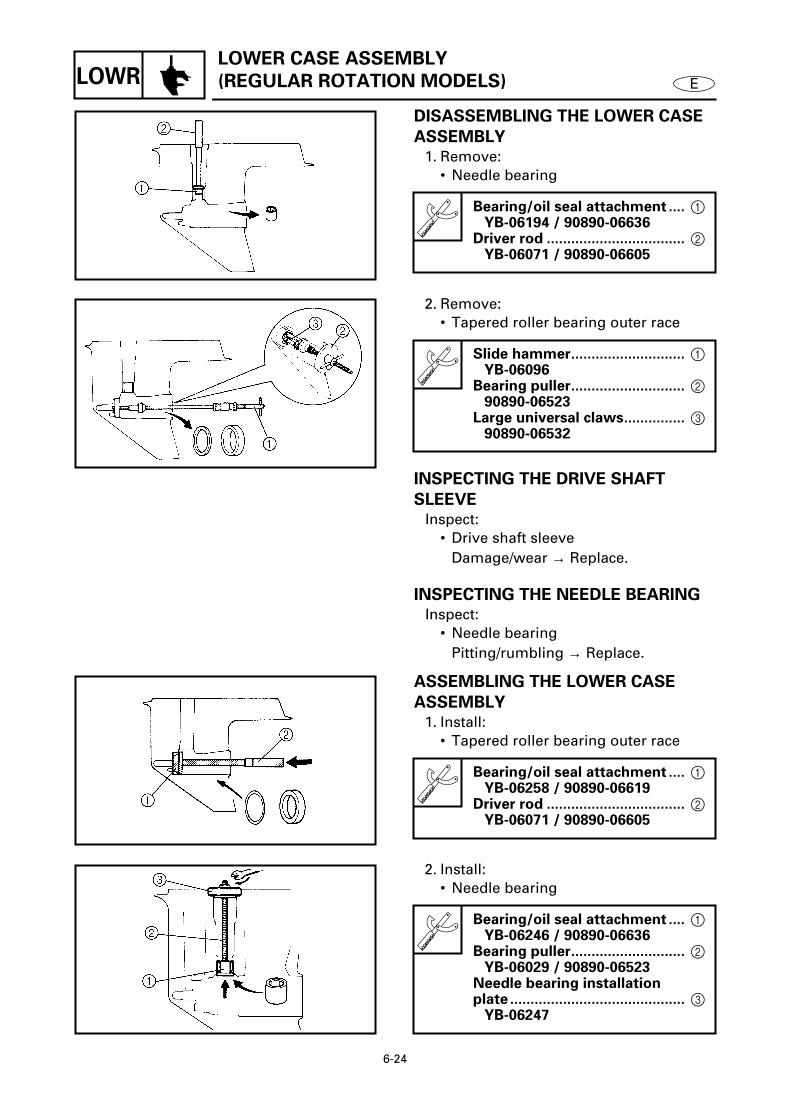
6-24
ELOWRLOWER CASE ASSEMBLY
(REGULAR ROTATION MODELS)
DISASSEMBLING THE LOWER CASE
ASSEMBLY
1. Remove:• Needle bearing
Bearing/oil seal attachment .... 1 YB-06194 / 90890-06636
Driver rod .................................. 2 YB-06071 / 90890-06605
6165
2. Remove:• Tapered roller bearing outer race
INSPECTING THE DRIVE SHAFT
SLEEVE
Inspect:• Drive shaft sleeve
Damage/wear → Replace.
INSPECTING THE NEEDLE BEARING
Inspect:• Needle bearing
Pitting/rumbling → Replace.
Slide hammer............................ 1 YB-06096
Bearing puller............................ 2 90890-06523
Large universal claws............... 3 90890-06532
6170
ASSEMBLING THE LOWER CASE
ASSEMBLY
1. Install:• Tapered roller bearing outer race
Bearing/oil seal attachment .... 1 YB-06258 / 90890-06619
Driver rod .................................. 2 YB-06071 / 90890-06605
6175
2. Install:• Needle bearing
Bearing/oil seal attachment .... 1 YB-06246 / 90890-06636
Bearing puller............................ 2 YB-06029 / 90890-06523
Needle bearing installation plate ........................................... 3
YB-062476180

6-25
ELOWR LOWER UNIT (COUNTER ROTATION MODELS)
LOWER UNIT (COUNTER ROTATION MODELS) 6REMOVING/INSTALLING THE LOWER UNIT
Order Job/Part Q’ty Remarks1 Speedometer hose 12 Cotter pin 13 Propeller nut 14 Washer 15 Washer 16 Propeller 17 Spacer 1
Continued on next page.
6011

6-26
ELOWR
6
Order Job/Part Q’ty Remarks8 Bolt 19 Trim tab 110 Bolt 1 (with washer)11 Bolt 6 (with washer)12 Lower unit 113 Dowel pin 2
For installation, reverse the removal procedure.
6011
LOWER UNIT (COUNTER ROTATION MODELS)

6-27
ELOWR
REMOVING THE PROPELLER
Remove:• Propeller
WARNING
Do not hold the propeller with your hands
when removing or installing it. Be sure to
remove the battery leads from the batteries
and the lanyard engine stop switch. Put a
block of wood between the cavitation plate
and propeller to keep the propeller from
turning.
6018
INSPECTING THE PROPELLER
Inspect:• Blades• Splines
Cracks/damage/wear → Replace.
INSTALLING THE PROPELLER
Install:• Propeller
WARNING
Do not hold the propeller with your hands
when removing or installing it. Be sure to
remove the battery leads from the batteries
and the lanyard engine stop switch. Put a
block of wood between the cavitation plate
and propeller to keep the propeller from
turning.
NOTE:
If the groove in the propeller nut is notaligned with the cotter pin hole, tighten thenut further until they are aligned.
6019
LOWER UNIT (COUNTER ROTATION MODELS)

6-28
ELOWR WATER PUMP (COUNTER ROTATION MODELS)
WATER PUMP (COUNTER ROTATION MODELS) 6REMOVING/INSTALLING THE WATER PUMP
Order Job/Part Q’ty RemarksLower unit Refer to “LOWER UNIT (COUNTER
ROTATION MODELS)” on page 6-25.1 Bolt 42 Plate washer 43 Impeller housing 14 Impeller housing cup 15 Grommet 16 Spacer 17 Collar 1
Continued on next page.
6020

6-29
ELOWR
6
Order Job/Part Q’ty Remarks8 Spacer 19 Washer 210 Wave washer 111 Impeller 112 Woodruff key 113 Impeller plate 114 Gasket 115 Dowel pin 2
For installation, reverse the removal procedure.
6020
Not reusable
WATER PUMP (COUNTER ROTATION MODELS)

6-30
ELOWR
INSPECTING THE IMPELLER
HOUSING
Inspect:• Impeller housing
Cracks/damage → Replace.
INSPECTING THE IMPELLER AND
IMPELLER HOUSING CUP
Inspect:• Impeller• Impeller housing cup
Cracks/damage → Replace any defec-tive parts.
INSPECTING THE WOODRUFF KEY
Inspect:• Woodruff key
Damage/wear → Replace.
INSTALLING THE IMPELLER AND
IMPELLER HOUSING
1. Install:• Washers 1 • Wave washer 2 • Spacer 3 • Collar 4
NOTE:
• The collar and spacer should fit togetherfirmly.
• Install the collar with some appropriatetool a that fits over the drive shaft asshown.
2. Install:• O-ring 1 • Impeller housing cup 2 • Impeller housing 3 • O-ring 4
NOTE:
• When installing the impeller housing cup,align its projection with the hole in theimpeller housing.
• When installing the water pump housing,turn the drive shaft clockwise.
6025
6030
WATER PUMP (COUNTER ROTATION MODELS)

6-31
ELOWR
SHIFT ROD ASSEMBLY
(COUNTER ROTATION MODELS)
SHIFT ROD ASSEMBLY (COUNTER ROTATION MODELS) 6
REMOVING/INSTALLING THE SHIFT ROD ASSEMBLY
Order Job/Part Q’ty RemarksImpeller plate Refer to “WATER PUMP (COUNTER
ROTATION MODELS)” on page 6-28.1 Bolt 3 (with washer)2 Shift rod assembly 13 Shift rod 14 Spring 15 Oil seal housing 16 Oil seal 1
For installation, reverse the removal procedure.
6195

6-32
ELOWR
REMOVING THE SHIFT ROD
ASSEMBLY
Remove:• Shift rod assembly
NOTE:
Remove the shift rod assembly when the
shift rod is in the neutral position.
SHIFT ROD ASSEMBLY
(COUNTER ROTATION MODELS)

6-33
ELOWR
PROPELLER SHAFT HOUSING ASSEMBLY
(COUNTER ROTATION MODELS)
PROPELLER SHAFT HOUSING ASSEMBLY (COUNTER ROTATION MODELS) 6
REMOVING/INSTALLING THE PROPELLER SHAFT HOUSING ASSEMBLY
Order Job/Part Q’ty RemarksGear oil Refer to “CHANGING AND INSPECTING
THE GEAR OIL” on page 3-17.Shift rod assembly Refer to “SHIFT ROD ASSEMBLY
(COUNTER ROTATION MODELS)” on page 6-31.
1 Ring nut 12 Claw washer 13 Propeller shaft housing assembly 14 Straight key 15 Reverse gear shim *
For installation, reverse the removal procedure.
*: As required
6200

6-34
ELOWR
PROPELLER SHAFT HOUSING ASSEMBLY
(COUNTER ROTATION MODELS)
6
DISASSEMBLING/ASSEMBLING THE PROPELLER SHAFT HOUSING ASSEMBLY
Order Job/Part Q’ty Remarks1 O-ring 12 Spring 13 Pin 14 Dog clutch 15 Forward gear assembly 16 Propeller shaft assembly 17 Thrust bearing 18 Propeller shaft shim *
Continued on next page.
*: As required
6205

6-35
ELOWR
6
Order Job/Part Q’ty Remarks9 Oil seal 210 Needle bearing 111 Propeller shaft housing 112 Forward gear 113 Thrust washer 114 Tapered roller bearing outer race 115 Tapered roller bearing 1
For assembly, reverse the disassembly procedure.
6205
Not reusable
PROPELLER SHAFT HOUSING ASSEMBLY
(COUNTER ROTATION MODELS)

6-36
ELOWR
PROPELLER SHAFT HOUSING ASSEMBLY
(COUNTER ROTATION MODELS)
6
DISASSEMBLING/ASSEMBLING THE PROPELLER SHAFT ASSEMBLY
Order Job/Part Q’ty Remarks1 Shift rod joint 12 Shift rod joint slider 13 Ball 44 Spring 15 Ball 26 Propeller shaft 1
For assembly, reverse the disassembly procedure.
6235

6-37
ELOWR
PROPELLER SHAFT HOUSING ASSEMBLY
(COUNTER ROTATION MODELS)
REMOVING THE PROPELLER SHAFT
HOUSING ASSEMBLY
1. Straighten:• Claw washer tabs.
2. Remove:• Ring nut• Claw washer
Ring nut wrench .......................
1
YB-34447 / 90890-06512
Ring nut wrench extension .....
2
90890-06513
6050
3. Remove:• Propeller shaft housing assembly
Slide hammer attachment.......
1
YB-06335 / 90890-06514
Slide hammer............................
2
YB-06096 / 90890-06531
6215
REMOVING THE PROPELLER SHAFT
ASSEMBLY
Remove:• Propeller shaft assembly• Forward gear assembly
Propeller shaft housing puller .
1
YB-06207 / 90890-06502
Universal pullerYB-06117
Guide plate................................
2
90890-06501
Center bolt ................................
3
90890-06504
6220

6-38
ELOWR
PROPELLER SHAFT HOUSING ASSEMBLY
(COUNTER ROTATION MODELS)
DISASSEMBLING THE PROPELLER
SHAFT HOUSING ASSEMBLY
Remove:• Oil seal• Needle bearing
DISASSEMBLING THE FORWARD
GEAR ASSEMBLY
Remove:• Tapered roller bearing
CAUTION:
Do not reuse the bearing, always replace it
with a new one.
Bearing/oil seal attachment ....
1
YB-06196 / 90890-06653
Driver rod ..................................
2
YB-06071 / 90890-06652
Bearing separatorYB-06219 / 90890-06534
6225
6230
INSPECTING THE FORWARD GEAR
Inspect:• Teeth• Dogs
Damage/wear
→
Replace.
INSPECTING THE BEARING
Inspect:• Bearing
Pitting/rumbling
→
Replace.
INSPECTING THE PROPELLER SHAFT
HOUSING
Inspect:• Propeller shaft housing
Cracks/damage
→
Replace.

6-39
ELOWR
PROPELLER SHAFT HOUSING ASSEMBLY
(COUNTER ROTATION MODELS)
INSPECTING THE DOG CLUTCH
Inspect:• Dog clutch
Damage/wear
→
Replace.
INSPECTING THE PROPELLER SHAFT
Inspect:• Propeller shaft
Damage/wear
→
Replace.
ASSEMBLING THE PROPELLER
SHAFT HOUSING
1. Install:• Needle bearing
Å
For USA and Canada
ı
Except for USA and Canada
Needle bearing installation position
a
24.75 - 25.25 mm (0.974 - 0.994 in)
Bearing/oil seal attachment ....
1
YB-06196 / 90890-06610
Driver rod ..................................
2
YB-06071 / 90890-06604
Bearing/oil seal depth plate ....
3
90890-06603
6231
Å
6086
ı
2. Install:• Oil seal
Oil seal installation position
a
4.75 - 5.25 mm (0.187 - 0.207 in)
Bearing/oil seal attachmentYB-06195 / 90890-06633
6232

6-40
ELOWR
PROPELLER SHAFT HOUSING ASSEMBLY
(COUNTER ROTATION MODELS)
INSTALLING THE PROPELLER SHAFT
ASSEMBLY
Install:• Forward gear assembly• Propeller shaft assembly
6233
INSTALLING THE PROPELLER SHAFT
HOUSING ASSEMBLY
Install:• Propeller shaft housing assembly• Claw washer• Ring nut
NOTE:
To secure the ring nut, bend one tab intothe slot in the ring nut and the other tabstoward the propeller shaft housing assem-
bly.
Ring nut wrench .......................
1 YB-34447 / 90890-06512
Ring nut wrench extension ..... 2 90890-06513
6095

6-41
ELOWR DRIVE SHAFT (COUNTER ROTATION MODELS)
DRIVE SHAFT (COUNTER ROTATION MODELS) 6REMOVING/INSTALLING THE DRIVE SHAFT
Order Job/Part Q’ty RemarksPropeller shaft housing assembly Refer to “PROPELLER SHAFT HOUSING
ASSEMBLY (COUNTER ROTATION MODELS)” on page 6-33.
1 Nut 12 Pinion 13 Bolt 4 (with washer)4 Drive shaft housing assembly 15 Pinion shim *6 Thrust bearing 17 Drive shaft 1
Continued on next page.
*: As required
6240

6-42
ELOWR
6
Order Job/Part Q’ty Remarks8 Reverse gear assembly 19 Thrust bearing 110 O-ring 111 Oil seal cover 112 Oil seal 213 Needle bearing 114 Drive shaft housing 115 Roller bearing inner race 116 Needle bearing 217 Reverse gear 1
For installation, reverse the removal procedure.
6240
DRIVE SHAFT (COUNTER ROTATION MODELS)
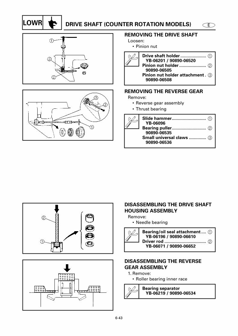
6-43
ELOWR
REMOVING THE DRIVE SHAFT
Loosen:• Pinion nut
Drive shaft holder ..................... 1 YB-06201 / 90890-06520
Pinion nut holder ...................... 2 90890-06505
Pinion nut holder attachment . 3 90890-065086110
REMOVING THE REVERSE GEAR
Remove:• Reverse gear assembly• Thrust bearing
Slide hammer............................ 1 YB-06096
Bearing puller............................ 2 90890-06535
Small universal claws .............. 3 90890-06536
6250
DISASSEMBLING THE DRIVE SHAFT
HOUSING ASSEMBLY
Remove:• Needle bearing
Bearing/oil seal attachment .... 1 YB-06196 / 90890-06610
Driver rod .................................. 2 YB-06071 / 90890-06652
6120
DISASSEMBLING THE REVERSE
GEAR ASSEMBLY
1. Remove:• Roller bearing inner race
Bearing separatorYB-06219 / 90890-06534
6270
DRIVE SHAFT (COUNTER ROTATION MODELS)

6-44
ELOWR DRIVE SHAFT (COUNTER ROTATION MODELS)
2. Remove:• Needle bearing
Slide hammer............................ 1 YB-06096
Guide plate................................ 2 90890-06501
Guide plate stand ..................... 3 90890-06538
Bearing puller............................ 4 90890-06535
Small universal claws .............. 5 90890-06536
6275
INSPECTING THE PINION
Inspect:• Teeth
Damage/wear → Replace.
INSPECTING THE DRIVE SHAFT
Inspect:• Drive shaft
Damage/wear → Replace.
INSPECTING THE DRIVE SHAFT
HOUSING
Inspect:• Drive shaft housing
Cracks/damage → Replace.
INSPECTING THE BEARINGS
Inspect:• Bearings
Pitting/rumbling → Replace.
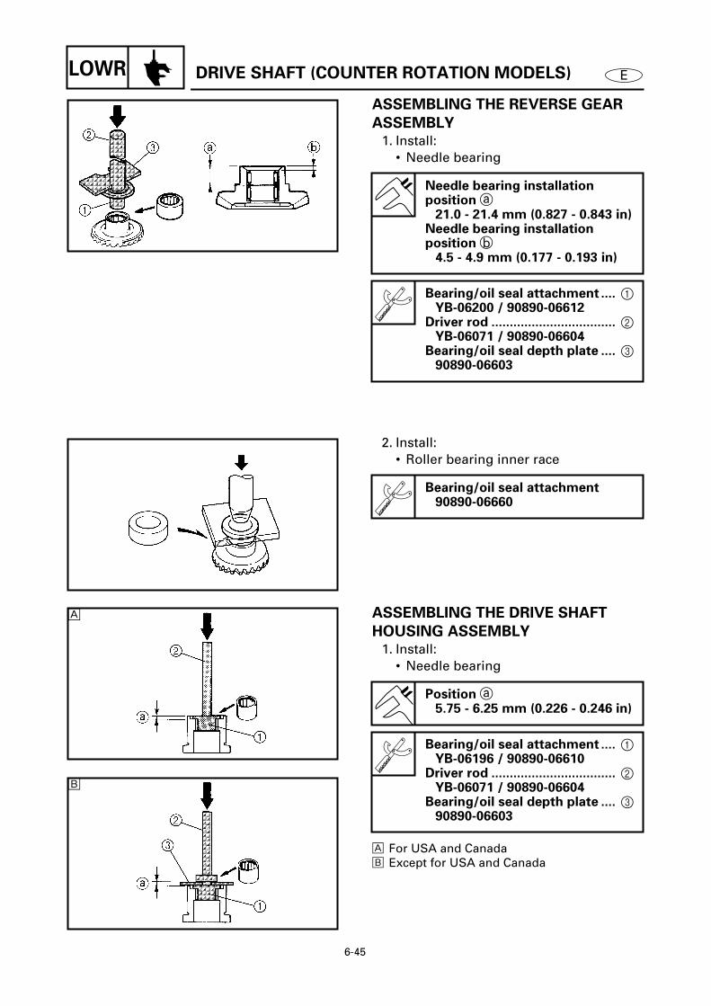
6-45
ELOWR DRIVE SHAFT (COUNTER ROTATION MODELS)
ASSEMBLING THE REVERSE GEAR
ASSEMBLY
1. Install:• Needle bearing
Needle bearing installation position a
21.0 - 21.4 mm (0.827 - 0.843 in)Needle bearing installation position b
4.5 - 4.9 mm (0.177 - 0.193 in)
Bearing/oil seal attachment .... 1 YB-06200 / 90890-06612
Driver rod .................................. 2 YB-06071 / 90890-06604
Bearing/oil seal depth plate .... 3 90890-06603
6150
2. Install:• Roller bearing inner race
Bearing/oil seal attachment90890-06660
6285
ASSEMBLING THE DRIVE SHAFT
HOUSING ASSEMBLY
1. Install:• Needle bearing
Å For USA and Canadaı Except for USA and Canada
Position a 5.75 - 6.25 mm (0.226 - 0.246 in)
Bearing/oil seal attachment .... 1 YB-06196 / 90890-06610
Driver rod .................................. 2 YB-06071 / 90890-06604
Bearing/oil seal depth plate .... 3 90890-06603
6125
Å
6126
ı

6-46
ELOWR
2. Install:• Oil seal
Oil seal installation position a0.25 - 0.75 mm (0.010 - 0.030 in)
Bearing/oil seal attachment .... 1 YB-06195 / 90890-06633
Driver rod .................................. 2 YB-06071 / 90890-066526130
INSTALLING THE REVERSE GEAR
Install:• Thrust bearing • Reverse gear assembly
NOTE:
Install the thrust bearing onto the reversegear assembly and position the thrust bear-ing so its rounded side faces away from thereverse gear.
INSTALLING THE DRIVE SHAFT
Tighten:• Pinion nut
NOTE:
Tighten the pinion nut with the same toolsthat were used for removal.
T R.
.
Pinion nut95 Nm (9.5 m • kgf, 68 ft • lb)
6255
DRIVE SHAFT (COUNTER ROTATION MODELS)

6-47
ELOWRLOWER CASE ASSEMBLY
(COUNTER ROTATION MODELS)
LOWER CASE ASSEMBLY (COUNTER ROTATION MODELS) 6DISASSEMBLING/ASSEMBLING THE LOWER CASE ASSEMBLY
Order Job/Part Q’ty RemarksReverse gear Refer to “DRIVE SHAFT (COUNTER
ROTATION MODELS)” on page 6-41.1 Drive shaft sleeve 12 Needle bearing 183 Needle bearing outer case 14 Roller bearing 15 Reverse gear shim *6 Water seal 17 Plate 1
For assembly, reverse the disassembly procedure.
*: As required
6290

6-48
ELOWRLOWER CASE ASSEMBLY
(COUNTER ROTATION MODELS)
DISASSEMBLING THE LOWER CASE
ASSEMBLY
1. Remove:• Needle bearing outer race
Bearing/oil seal attachment .... 1 YB-06194 / 90890-06636
Driver rod .................................. 2 YB-06071 / 90890-06605
6313
2. Remove:• Roller bearing
INSPECTING THE DRIVE SHAFT
SLEEVE
Inspect:• Drive shaft sleeve
Damage/wear → Replace.
INSPECTING THE NEEDLE BEARING
Inspect:• Needle bearing
Pitting/rumbling → Replace.
Slide hammer............................ 1 YB-06096
Bearing puller............................ 2 90890-06523
Large universal claws............... 3 90890-06532
6300
ASSEMBLING THE LOWER CASE
ASSEMBLY
1. Install:• Roller bearing
Bearing/oil seal attachment .... 1 YB-06336 / 90890-06629
Driver rod .................................. 2 YB-06071 / 90890-06605
6305
2. Install:• Needle bearing outer race
Bearing/oil seal attachment .... 1 YB-06246 / 90890-06636
Bearing puller............................ 2 YB-06029 / 90890-06523
Needle bearing installation plate ........................................... 3
YB-062476314

6-49
ELOWR LOWER UNIT (DUAL PROPELLER MODELS)
LOWER UNIT (DUAL PROPELLER MODELS) 6REMOVING/INSTALLING THE LOWER UNIT
Order Job/Part Q’ty Remarks1 Speedometer hose 12 Cotter pin 13 Propeller nut 14 Washer 15 Washer 16 Rear propeller 17 Rear spacer 18 Propeller nut 1
Continued on next page.
6315

6-50
ELOWR LOWER UNIT (DUAL PROPELLER MODELS)
6
Order Job/Part Q’ty Remarks9 Toothed washer 110 Forward propeller 111 Forward spacer 112 Bolt 7 (with washer)13 Lower unit 114 Dowel pin 2
For installation, reverse the removal procedure.
6315

6-51
ELOWR LOWER UNIT (DUAL PROPELLER MODELS)
REMOVING THE PROPELLERS
1. Remove:• Rear propeller
WARNING
Do not hold the propeller with your hands
when removing or installing it. Be sure to
remove the battery leads from the batteries
and the lanyard engine stop switch. Put a
block of wood between the cavitation plate
and propeller to keep the propeller from
turning.
2. Straighten:• Toothed washer teeth
6321
3. Remove:• Forward propeller
WARNING
Do not hold the propeller with your hands
when removing or installing it. Be sure to
remove the battery leads from the batteries
and the lanyard engine stop switch. Put a
block of wood between the cavitation plate
and propeller to keep the propeller from
turning.
6326
INSPECTING THE PROPELLERS
Inspect:• Blades• Splines
Cracks/damage/wear → Replace.

6-52
ELOWR LOWER UNIT (DUAL PROPELLER MODELS)
INSTALLING THE PROPELLERS
1. Install:• Forward propeller
WARNING
Do not hold the propeller with your hands
when removing or installing it. Be sure to
remove the battery leads from the batteries
and the lanyard engine stop switch. Put a
block of wood between the cavitation plate
and propeller to keep the propeller from
turning.
6327
2. Bend:• Toothed washer teeth
3. Install:• Rear propeller
WARNING
Do not hold the propeller with your hands
when removing or installing it. Be sure to
remove the battery leads from the batteries
and the lanyard engine stop switch. Put a
block of wood between the cavitation plate
and propeller to keep the propeller from
turning.
NOTE:
If the groove in the propeller nut is notaligned with the cotter pin hole, tighten thenut further until they are aligned.
6328

6-53
ELOWR WATER PUMP (DUAL PROPELLER MODELS)
WATER PUMP (DUAL PROPELLER MODELS) 6REMOVING/INSTALLING THE WATER PUMP
Order Job/Part Q’ty RemarksLower unit Refer to “LOWER UNIT (DUAL
PROPELLER MODELS)” on page 6-49.1 Bolt 42 Plate washer 43 Impeller housing 14 Impeller housing cup 15 Grommet 16 Spacer 17 Drive shaft collar 1
Continued on next page.
6330

6-54
ELOWR
6
Order Job/Part Q’ty Remarks8 Spacer 19 Washer 210 Wave washer 111 Impeller 112 Woodruff key 1
For installation, reverse the removal procedure.
6330
WATER PUMP (DUAL PROPELLER MODELS)

6-55
ELOWR
INSPECTING THE IMPELLER
HOUSING
Inspect:• Impeller housing
Cracks/damage → Replace.
INSPECTING THE IMPELLER AND
IMPELLER HOUSING CUP
Inspect:• Impeller• Impeller housing cup
Cracks/damage → Replace any defec-tive parts.
INSPECTING THE WOODRUFF KEY
Inspect:• Woodruff key
Damage/wear → Replace.
INSTALLING THE IMPELLER AND
IMPELLER HOUSING
1. Install:• Washers 1 • Wave washer 2 • Spacer 3 • Collar 4
NOTE:
• The collar and spacer should fit togetherfirmly.
• Install the collar with some appropriatetool a that fits over the drive shaft asshown.
2. Install:• O-ring 1 • Impeller housing cup 2 • Impeller housing 3 • O-ring 4
NOTE:
• When installing the impeller housing cup,align its projection with the hole in theimpeller housing.
• When installing the water pump housing,turn the drive shaft clockwise.
6025
6030
WATER PUMP (DUAL PROPELLER MODELS)

6-56
ELOWR SHIFT ROD (DUAL PROPELLER MODELS)
SHIFT ROD (DUAL PROPELLER MODELS) 6REMOVING/INSTALLING THE SHIFT ROD
Order Job/Part Q’ty RemarksWoodruff key Refer to “WATER PUMP (DUAL
PROPELLER MODELS)” on page 6-53.1 Bolt 3 (with washer)2 Plate washer 33 Oil seal housing cover 14 Impeller plate 15 Gasket 16 Oil seal housing 17 O-ring 18 Shift rod 1
For installation, reverse the removal procedure.
6335
Not reusable
Not reusable

6-57
ELOWR SHIFT ROD (DUAL PROPELLER MODELS)
REMOVING THE SHIFT ROD
1. Remove:• Oil seal housing
Removing steps
(1) Insert a flat-head screwdriver undereach projection a.
(2) Alternating between each side of theoil seal housing 1, slowly lift the oilseal housing until it is fully removedfrom the lower unit.
2. Remove:• Shift rod
NOTE:
Remove the shift rod when it is in the neu-tral position.
a
1
6336

6-58
ELOWRPROPELLER SHAFT HOUSING ASSEMBLY
(DUAL PROPELLER MODELS)
PROPELLER SHAFT HOUSING ASSEMBLY (DUAL PROPELLER MODELS) 6REMOVING/INSTALLING THE PROPELLER SHAFT HOUSING ASSEMBLY
Order Job/Part Q’ty RemarksGear oil Refer to “CHANGING AND INSPECTING
THE GEAR OIL” on page 3-17.1 Ring nut 12 Claw washer 13 Propeller shaft housing assembly 14 Washer 15 Rear gear shim *
For installation, reverse the removal procedure.
*: As required
6340

6-59
ELOWRPROPELLER SHAFT HOUSING ASSEMBLY
(DUAL PROPELLER MODELS)
6DISASSEMBLING/ASSEMBLING THE PROPELLER SHAFT HOUSING ASSEMBLY
Order Job/Part Q’ty Remarks1 O-ring 32 Rear gear assembly 13 Outer propeller shaft 14 Thrust bearing 15 Outer propeller shaft shim *6 Oil seal 27 Needle bearing 2
Continued on next page.
*: As required
6345

6-60
ELOWRPROPELLER SHAFT HOUSING ASSEMBLY
(DUAL PROPELLER MODELS)
6
Order Job/Part Q’ty Remarks8 Oil seal 29 Needle bearing 110 Propeller shaft housing 111 Rear gear 112 Thrust washer 113 Tapered roller bearing outer race 114 Tapered roller bearing 1
For assembly, reverse the disassembly procedure.
6345

6-61
ELOWR
PROPELLER SHAFT HOUSING ASSEMBLY
(DUAL PROPELLER MODELS)
REMOVING THE PROPELLER SHAFT
HOUSING ASSEMBLY
1. Straighten: • Claw washer tabs
2. Remove:• Ring nut• Claw washer
3. Remove:• Propeller shaft housing
Ring nut wrenchYB-42223
Propeller shaft housing puller .
1
YB-06502 / 90890-06502
Universal puller.........................
2
YB-06540 / 90890-06540
6350
2 1
6355
REMOVING THE OUTER PROPELLER
SHAFT
Remove:• Rear gear assembly
1
• Outer propeller shaft
2
• Thrust bearing
3
• Outer propeller shaft shim
4
6360
DISASSEMBLING THE PROPELLER
SHAFT HOUSING ASSEMBLY
Remove:• Needle bearing
Slide hammerYB-06096
6365

6-62
ELOWR
PROPELLER SHAFT HOUSING ASSEMBLY
(DUAL PROPELLER MODELS)
DISASSEMBLING THE OUTER
PROPELLER SHAFT ASSEMBLY
Remove:• Needle bearing
Slide hammerYB-06096
6370
REMOVING THE REAR GEAR
ASSEMBLY
Remove:• Rear gear
1
• Thrust washer
2
• Tapered roller bearing
3
• Tapered roller bearing outer race
4
INSPECTING THE BEARINGS
Inspect:• Needle bearing• Thrust bearing• Tapered roller bearing
Pitting/rumbling
→
Replace.
INSPECTING THE PROPELLER SHAFT
HOUSING
Inspect:• Propeller shaft housing
Cracks/damage
→
Replace.
INSPECTING THE OUTER PROPELLER
SHAFT
Inspect:• Splines
Damage/wear
→
Replace.
INSPECTING THE REAR GEAR
Inspect:• Teeth• Dogs
Damage/wear
→
Replace.
Bearing separatorYB-06219 / 90890-06534
2
1
3
4
6371

6-63
ELOWR
PROPELLER SHAFT HOUSING ASSEMBLY
(DUAL PROPELLER MODELS)
ASSEMBLING THE OUTER
PROPELLER SHAFT ASSEMBLY
1. Install:• Needle bearing
Å
For USA and Canada
ı
Except for USA and Canada
2. Install:• Oil seal
Needle bearing installation position
a
34.75 - 35.25 mm (1.368 - 1.388 in)
Bearing/oil seal attachment ....
1
YB-42225 / 90890-06653
Driver rod ..................................
2
YB-06071 / 90890-06604
Bearing/oil seal depth plate ....
3
90890-06603
Oil seal installation position
a
2.75 - 3.25 mm (0.108 - 0.128 in)
Bearing/oil seal attachment ....
1
YB-42225 / 90890-06636
Driver rod ..................................
2
YB-06071 / 90890-06606
6375
Å
6376
ı
6380
ASSEMBLING THE PROPELLER
SHAFT HOUSING ASSEMBLY
1. Install:• Rear needle bearing
Å
For USA and Canada
ı
Except for USA and Canada
Rear needle bearing installation position
a
24.75 - 25.25 mm (0.974 - 0.994 in)
Bearing/oil seal attachment ....
1
YB-42227 / 90890-06607
Driver rod ..................................
2
YB-06071 / 90890-06604
Bearing/oil seal depth plate ....
3
90890-06603
6385
Å
6086
ı

6-64
ELOWR
PROPELLER SHAFT HOUSING ASSEMBLY
(DUAL PROPELLER MODELS)
2. Install:• Oil seal
3. Install:• Front needle bearing
4. Install:• Outer propeller shaft
NOTE:
When installing the outer propeller shaftinto the propeller shaft housing assembly,wrap the entire threaded and splined por-tion of the outer propeller shaft to protect
the oil seal lip from damage.
5. Install:• Tapered roller bearing
1
• Tapered roller bearing outer race
2
Oil seal installation position a4.75 - 5.25 mm (0.187 - 0.207 in)
Bearing/oil seal attachment .... 1 YB-42227 / 90890-06623
Driver rod .................................. 2 YB-06071 / 90890-06606
Front needle bearing installation position a
0.75 - 1.25 mm (0.030 - 0.049 in)
Bearing/oil seal attachment .... 1 YB-42229 / 90890-06607
Driver rod .................................. 2 YB-06071 / 90890-06604
6390
6395
6400
6396
6. Install:• Thrust washer 1 • Rear gear 2
6397
2
1
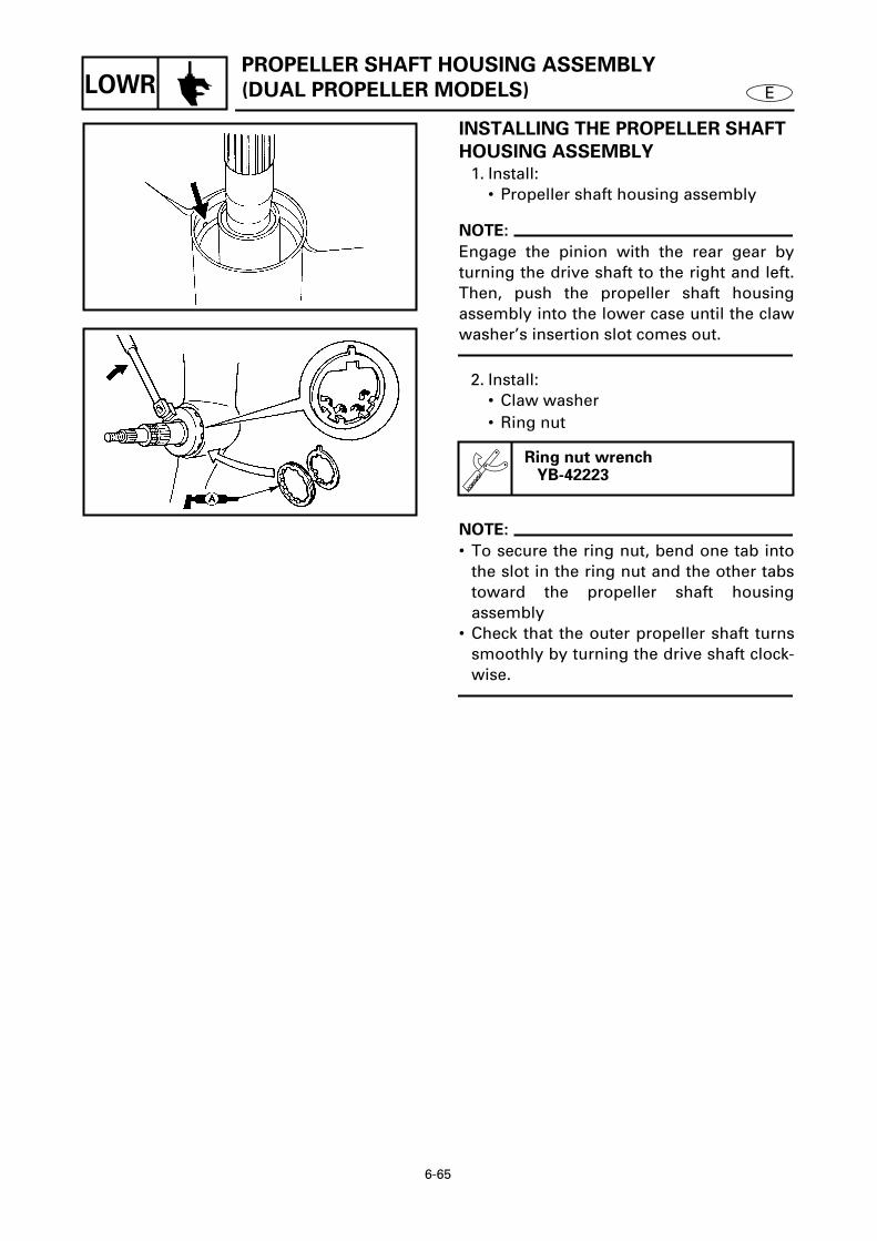
6-65
ELOWRPROPELLER SHAFT HOUSING ASSEMBLY
(DUAL PROPELLER MODELS)
INSTALLING THE PROPELLER SHAFT
HOUSING ASSEMBLY
1. Install:• Propeller shaft housing assembly
NOTE:
Engage the pinion with the rear gear byturning the drive shaft to the right and left.Then, push the propeller shaft housingassembly into the lower case until the clawwasher’s insertion slot comes out.
2. Install:• Claw washer• Ring nut
NOTE:
• To secure the ring nut, bend one tab intothe slot in the ring nut and the other tabstoward the propeller shaft housingassembly
• Check that the outer propeller shaft turnssmoothly by turning the drive shaft clock-wise.
Ring nut wrenchYB-42223
6410
6405

6-66
ELOWR
DRIVE SHAFT (DUAL PROPELLER MODELS) 6REMOVING/INSTALLING THE DRIVE SHAFT
Order Job/Part Q’ty RemarksPropeller shaft housing assembly Refer to “PROPELLER SHAFT HOUSING
ASSEMBLY (DUAL PROPELLER MODELS)” on page 6-58.
Shift rod Refer to “SHIFT ROD (DUAL PROPELLER MODELS)” on page 6-56.
1 Nut 12 Pinion 13 Bolt 44 Drive shaft housing assembly 15 Pinion shim *
Continued on next page.
*: As required
6415
DRIVE SHAFT (DUAL PROPELLER MODELS)

6-67
ELOWR
6
Order Job/Part Q’ty Remarks6 Thrust bearing 17 Drive shaft 18 Inner propeller shaft assembly 19 O-ring 110 Oil seal cover 111 Oil seal 212 Needle bearing 113 Drive shaft housing 1
For installation, reverse the removal procedure.
6415
DRIVE SHAFT (DUAL PROPELLER MODELS)

6-68
ELOWR
REMOVING THE DRIVE SHAFT
Loosen:• Pinion nut
NOTE:
• First, loosen the drive shaft housingassembly bolts. Then, pull up the driveshaft and insert the pinion nut holder.
• Retighten the drive shaft housing assem-bly bolts and then loosen the pinion nut.
INSPECTING THE PINION
Inspect:• Teeth
Damage/wear → Replace.
INSPECTING THE DRIVE SHAFT
Inspect:• Drive shaft
Damage/wear → Replace.
Drive shaft holder ..................... 1 YB-06201 / 90890-06520
Pinion nut holder ...................... 2 YB-42224
6420
INSTALLING THE DRIVE SHAFT
Tighten:• Pinion nut
NOTE:
• Tighten the pinion nut with the same toolsthat were used for removal.
• Tighten the pinion nut while slightly liftingthe inner propeller shaft assembly 1.
T R.
.
Pinion nut95 Nm (9.5 m • kgf, 68 ft • lb)
6421
DRIVE SHAFT (DUAL PROPELLER MODELS)

6-69
ELOWR
DISASSEMBLING THE DRIVE SHAFT
HOUSING ASSEMBLY
Remove:• Needle bearing
INSPECTING THE DRIVE SHAFT
HOUSING
Inspect:• Drive shaft housing
Cracks/damage → Replace.
Bearing/oil seal attachment .... 1 YB-06196 / 90890-06610
Driver rod .................................. 2 YB-06071 / 90890-06652
6120
ASSEMBLING THE DRIVE SHAFT
HOUSING ASSEMBLY
1. Install:• Needle bearing
Å For USA and Canadaı Except for USA and Canada
Position a 5.75 - 6.25 mm (0.226 - 0.246 in)
Bearing/oil seal attachment .... 1 YB-06196 / 90890-06610
Driver rod .................................. 2 YB-06071 / 90890-06604
Bearing/oil seal depth plate .... 3 90890-06603
6125
Å
6126
ı
2. Install:• Oil seal
Oil seal installation position a0.25 - 0.75 mm (0.010 - 0.030 in)
Bearing/oil seal attachment .... 1 YB-06195 / 90890-06633
Driver rod .................................. 2 YB-06071 / 90890-066526130
DRIVE SHAFT (DUAL PROPELLER MODELS)

6-70
ELOWRINNER PROPELLER SHAFT ASSEMBLY
(DUAL PROPELLER MODELS)
INNER PROPELLER SHAFT ASSEMBLY (DUAL PROPELLER MODELS) 6DISASSEMBLING/ASSEMBLING THE INNER PROPELLER SHAFT ASSEMBLY
Order Job/Part Q’ty Remarks1 Spring 12 Pin 13 Front dog clutch 14 Front gear assembly 15 Washer 1 (with oil groove a)6 Spring 1
Continued on next page.
6430

6-71
ELOWRINNER PROPELLER SHAFT ASSEMBLY
(DUAL PROPELLER MODELS)
6
Order Job/Part Q’ty Remarks7 Rear dog clutch 18 Washer 29 Pin 110 Collar 111 Tapered roller bearing 112 Front gear 1
For assembly, reverse the disassembly procedure.
6430
Not reusable

6-72
ELOWRINNER PROPELLER SHAFT ASSEMBLY
(DUAL PROPELLER MODELS)
REMOVING THE SPRING
Remove:• Spring 1
NOTE:
Pry the end of the spring out of the groovein the dog clutch and then graduallyremove it.
6435
DISASSEMBLING THE FRONT GEAR
ASSEMBLY
Remove:• Bearing inner race
CAUTION:
Do not reuse the bearing, always replace it
with a new one.
INSPECTING THE DOG CLUTCHES
Inspect:• Dog clutches
Damage/wear → Replace.
INSPECTING THE INNER PROPELLER
SHAFT
Inspect:• Inner propeller shaft
Damage/wear → Replace.
INSPECTING THE BEARING
Inspect:• Tapered roller bearing
Pitting/rumbling → Replace.
INSPECTING THE FRONT GEAR
Inspect:• Teeth• Dogs
Damage/wear → Replace.
Bearing separatorYB-06219 / 90890-06534
6450

6-73
ELOWRINNER PROPELLER SHAFT ASSEMBLY
(DUAL PROPELLER MODELS)
ASSEMBLING THE FRONT GEAR
ASSEMBLY
Install:• Bearing inner race 1
Bearing/oil seal attachmentYB-06276 / 90890-06659
6455
INSTALLING THE SPRING
Install:• Spring 1
NOTE:
Push the end of the spring into the groovein the dog clutch and then gradually installit.
6440

6-74
ELOWRLOWER CASE ASSEMBLY
(DUAL PROPELLER MODELS)
LOWER CASE ASSEMBLY (DUAL PROPELLER MODELS) 6DISASSEMBLING/ASSEMBLING THE LOWER CASE ASSEMBLY
Order Job/Part Q’ty RemarksInner propeller shaft assembly Refer to “DRIVE SHAFT (DUAL
PROPELLER MODELS)” on page 6-66.1 Drive shaft sleeve 12 Needle bearing 13 Tapered roller bearing outer race 14 Front gear shim *
For assembly, reverse the disassembly procedure.
*: As required
6465

6-75
ELOWRLOWER CASE ASSEMBLY
(DUAL PROPELLER MODELS)
DISASSEMBLING THE LOWER CASE
ASSEMBLY
1. Remove:• Needle bearing
Bearing/oil seal attachment .... 1 YB-06194 / 90890-06636
Driver rod .................................. 2 YB-06071 / 90890-06605
6470
2. Remove:• Tapered roller bearing outer race
Slide hammer............................ 1 YB-06096
Bearing puller............................ 2 90890-06523
Large universal claws............... 3 90890-06532
6475
INSPECTING THE DRIVE SHAFT
SLEEVE
Inspect:• Drive shaft sleeve
Damage/wear → Replace.
INSPECTING THE NEEDLE BEARING
Inspect:• Needle bearing
Pitting/rumbling → Replace.
ASSEMBLING THE LOWER CASE
ASSEMBLY
1. Install:• Tapered roller bearing outer race
Bearing/oil seal attachment .... 1 YB-06258 / 90890-06619
Driver rod .................................. 2 YB-06071 / 90890-06605
6480

6-76
ELOWRLOWER CASE ASSEMBLY
(DUAL PROPELLER MODELS)
2. Install:• Needle bearing
Å For USA and Canadaı Except for USA and Canada
Needle bearing installation position a
10.0 mm (0.39 in)Needle bearing installation position b
139.0 mm (5.47 in)
Bearing/oil seal attachment .... 1 YB-06194 / 90890-06609
Driver rod .................................. 2 YB-06071 / 90890-06602
Bearing/oil seal depth plate .... 3 YB-06213 / 90890-06603YB-34474
Å
6485
ı
6490

6-77
ELOWR SHIMMING (REGULAR ROTATION MODELS)
SHIMMING (REGULAR ROTATION MODELS) 6
NOTE:
• There is no need to select shims whenreassembling with the original case andinner parts.
• Shim calculations are required when reas-sembling with the original inner parts anda new case (the difference between theoriginal inner parts and the new case).
• Measurements and adjustments arerequired when replacing the inner part(s).
6495

6-78
ELOWRSHIMMING (REGULAR ROTATION MODELS)
(FOR USA AND CANADA)
SELECTING THE PINION SHIMS
NOTE:
Find the shim thickness (T3) by selectingshims until the specified value (M0) isobtained with the special tool.
6505
1. Measure:• Specified measurement (M)
Out of specified value (M0) → Adjust.
Measuring steps
(1) Calculate the specified value (M0).
NOTE:
• “P” is the deviation of the lower casedimension from standard. It is stampedon the trim tab mounting surface of thelower case in 0.01-mm units. If the “P”mark is missing or unreadable, assume a“P” value of “0”, and check the backlashwhen the unit is assembled.
• If the “P” mark is negative (–), then sub-tract the “P” value from the measure-ment.
Example:If “P” is “+5”, thenM0 = 1.00 + (+5)/100 mm
= 1.00 + 0.05 mm = 1.05 mm
If “P” is “–3”, thenM0 = 1.00 + (–3)/100 mm
= 1.00 – 0.03 mm = 0.97 mm
Specified value (M0) =1.00 + P/100 mm
6520
M
6510

6-79
ELOWRSHIMMING (REGULAR ROTATION MODELS)
(FOR USA AND CANADA)
(2) Install the pinion height gauge, driveshaft, thrust bearing 1, and shim(s) 2.
NOTE:
If the original shim(s) is unavailable, startwith a 0.50-mm shim.
(3) Install the pinion and pinion nut.
Pinion height gaugeYB-34432-7, -11
T R.
.
Pinion nut95 Nm (9.5 m • kgf, 69 ft • lb)
6515
(4) Measure the specified measurement(M).
NOTE:
• Measure the clearance between the pin-ion height gauge and the lower surface ofthe pinion as shown.
• Perform the same measurement at threepoints on the pinion.
• Find the average of the measurements (M).
2. Adjust:• Shim thickness (T3)
Remove or add shim(s).
NOTE:
(M0) – (M) should be as close to “0” as pos-sible.
Available shim thickness0.10, 0.12, 0.15, 0.18, 0.30, 0.40and 0.50 mm
M
6520
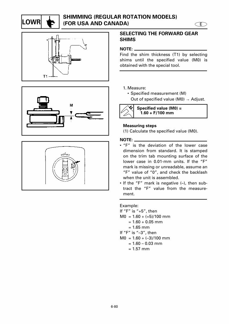
6-80
ELOWRSHIMMING (REGULAR ROTATION MODELS)
(FOR USA AND CANADA)
SELECTING THE FORWARD GEAR
SHIMS
NOTE:
Find the shim thickness (T1) by selectingshims until the specified value (M0) isobtained with the special tool.
6525
1. Measure:• Specified measurement (M)
Out of specified value (M0) → Adjust.
Measuring steps
(1) Calculate the specified value (M0).
NOTE:
• “F” is the deviation of the lower casedimension from standard. It is stampedon the trim tab mounting surface of thelower case in 0.01-mm units. If the “F”mark is missing or unreadable, assume an“F” value of “0”, and check the backlashwhen the unit is assembled.
• If the “F” mark is negative (–), then sub-tract the “F” value from the measure-ment.
Example: If “F” is “+5”, thenM0 = 1.60 + (+5)/100 mm
= 1.60 + 0.05 mm= 1.65 mm
If “F” is “–3”, thenM0 = 1.60 + (–3)/100 mm
= 1.60 – 0.03 mm= 1.57 mm
Specified value (M0) =1.60 + F/100 mm
6526
6530

6-81
ELOWRSHIMMING (REGULAR ROTATION MODELS)
(FOR USA AND CANADA)
(2) Install the shimming gauge, bearing1, and shim(s) 2.
NOTE:
If the original shim(s) is unavailable, startwith a 0.50-mm shim.
(3) Measure the specified measurement(M).
Shimming gaugeYB-34446-1, -3, -4, -8
6535
2. Adjust:• Shim thickness (T1)
Remove or add shim(s).
NOTE:
(M0) – (M) should be as close to “0” as pos-sible.
Available shim thickness0.10, 0.12, 0.15, 0.18, 0.30, 0.40and 0.50 mm

6-82
ELOWRSHIMMING (REGULAR ROTATION MODELS)
(FOR USA AND CANADA)
SELECTING THE REVERSE GEAR
SHIMS
NOTE:
Find the shim thickness (T2) by selectingshims until the specified value (M0) isobtained with the special tool.
6545
1. Measure:• Specified measurement (M)
Out of specified value (M0) → Adjust.
Measuring steps
(1) Calculate the specified value (M0).
NOTE:
• “R” is the deviation of the lower casedimension from standard. It is stampedon the trim tab mounting surface of thelower case in 0.01-mm units. If the “R”mark is missing or unreadable, assume an“R” value of “0”, and check the backlashwhen the unit is assembled.
• If the “R” mark is negative (–), then addthe “R” value to the measurement.
Example (150G/P150TR models): If “R” is “+5”, then M0 = 1.30 – (+5)/100 mm
= 1.30 – 0.05 mm = 1.25 mm
If “R” is “–3”, then M0 = 1.30 – (–3)/100 mm
= 1.30 + 0.03 mm = 1.33 mm
Specified value (M0) =(150A - 225D/C150TR - P200TR models)
1.80 – R/100 mm(150G/P150TR models)
1.30 – R/100 mm
M
6555
6550

6-83
ELOWRSHIMMING (REGULAR ROTATION MODELS)
(FOR USA AND CANADA)
(2) Install the shimming gauge, bearing,thrust washer, reverse gear, andshim(s).
NOTE:
• If the original shim(s) is unavailable, startwith a 0.50-mm shim.
• Turn the reverse gear assembly a fewtimes until the gear and bearing are hori-zontal.
(3) Measure the specified measurement(M).
2. Adjust:• Shim thickness (T2)
Remove or add shim(s).
NOTE:
(M0) – (M) should be as close to “0” as pos-sible.
Shimming gauge(150A - 225D/C150TR - P200TR models)
YB-34468-1 (150G/P150TR models)
YB-34468-6
Available shim thickness0.10, 0.12, 0.15, 0.18, 0.30, 0.40and 0.50 mm
M
6555

6-84
ELOWRSHIMMING (REGULAR ROTATION MODELS)
(EXCEPT FOR USA AND CANADA)
SELECTING THE PINION SHIMS
NOTE:
Select the shim thickness (T3) by using thespecified measurement(s) and the calcula-tion formula
Select:• Shim thickness (T3)
Selecting steps
(1) Measure (M3).
NOTE:
Install the bearing housing 1, thrust bear-ing 2, and washer 3.
(2) Install the pinion and pinion nut.
(3) Install the pinion height gauge.
NOTE:
After the wing nuts contact the fixing plate,tighten them another 1/4 of a turn.
(4) Measure (M4).
NOTE:
• Measure the clearance between the pin-ion height gauge and the pinion, asshown.
• Perform the same measurement at threepoints on the pinion.
• Find the average of the measurements(M4).
Digital caliper90890-06704
T R.
.
Pinion nut95 Nm (9.5 m • kgf, 69 ft • lb)
Pinion height gauge90890-06702
Digital caliper90890-06704
6575
6580
6585

6-85
ELOWRSHIMMING (REGULAR ROTATION MODELS)
(EXCEPT FOR USA AND CANADA)
(5) Calculate the pinion shim thickness(T3).
NOTE:
• “P” is the deviation of the lower casedimension from standard. It is stampedon the trim tab mounting surface of thelower case in 0.01-mm units. If the “P”mark is missing or unreadable, assume a“P” value of “0”, and check the backlashwhen the unit is assembled.
• If the “P” mark is negative (–), then addthe “P” value to the measurement.
Example:If M3 is “46.85 mm”, M4 is “32.52 mm” andP is “-5”, then T3 = 80.0 + (–5)/100 – 46.85 – 32.52 mm
= 80.0 – 0.05 – 46.85 – 32.52 mm= 0.58 mm
(6) Select the pinion shim(s) (T3).
Pinion shim thickness (T3) =80.0 + P/100 – M3 – M4
Calculated numeral
at 1/100th place Rounded
numeralMore than or less
0.00 0.02 0.00
0.02 0.05 0.02
0.05 0.08 0.05
0.08 0.10 0.08
Available shim thickness0.10, 0.12, 0.15, 0.18, 0.30, 0.40and 0.50 mm
6590

6-86
ELOWRSHIMMING (REGULAR ROTATION MODELS)
(EXCEPT FOR USA AND CANADA)
SELECTING THE FORWARD GEAR
SHIMS
NOTE:
Select the shim thickness (T1) by using thespecified measurement(s) and the calcula-tion formula.
Select:• Shim thickness (T1)
Selecting steps
(1) Measure (M1).
NOTE:
• Turn the roller bearing outer race two orthree times so the rollers seat. Then, mea-sure the height of the bearing, as shown.
• Perform the same measurement at threepoints on the roller bearing outer race.
• Find the average of the measurements(M1).
Shimming plate ........................ 1 90890-06701
Digital caliper ............................ 2 90890-06704
6595
6600
(2) Calculate the forward gear shim thick-ness (T1).
NOTE:
• “F” is the deviation of the lower casedimension from standard. It is stampedon the trim tab mounting surface of thelower case in 0.01-mm units. If the “F”mark is missing or unreadable, assume an“F” value of “0”, and check the backlashwhen the unit is assembled.
• If the “F” mark is negative (–), then sub-tract the “F” value from the measure-ment.
Forward gear shim thickness (T1)(T1) = 28.6 + F/100 – M1
6610

6-87
ELOWRSHIMMING (REGULAR ROTATION MODELS)
(EXCEPT FOR USA AND CANADA)
Example: If M1 is “28.10 mm” and F is “+5”, thenT1 = 28.6 + (+5)/100 – 28.10 mm
= 28.6 + 0.05 – 28.10 mm= 0.55 mm
(3) Select the forward gear shim(s) (T1).
Calculated numeral
at 1/100th place Rounded
numeralMore than or less
0.00 0.02 0.00
0.02 0.05 0.02
0.05 0.08 0.05
0.08 0.10 0.08
Available shim thickness0.10, 0.12, 0.15, 0.18, 0.30, 0.40and 0.50 mm
SELECTING THE REVERSE GEAR
SHIM
NOTE:
Select the shim thickness (T2) by using thespecified measurement(s) and the calcula-tion formula.
6615
Select:• Shim thickness (T2)
Selecting steps
(1) Measure (M2).
NOTE:
• Measure the height of the gear as shown.• Perform the same measurement at three
points on the gear.• Find the average of the measurements
(M2).
Shimming plate ........................ 1 90890-06701
Digital caliper ............................ 2 90890-067046620

6-88
ELOWRSHIMMING (REGULAR ROTATION MODELS)
(EXCEPT FOR USA AND CANADA)
(2) Calculate the reverse gear shim thick-ness (T2).
NOTE:
• “R” is the deviation of the lower casedimension from standard. It is stampedon the trim tab mounting surface of thelower case in 0.01-mm units. If the “R”mark is missing or unreadable, assume a“R” value of “0”, and check the backlashwhen the unit is assembled.
• If the “R” mark is negative (–), then sub-tract the “R” value from the measure-ment.
Example (150G/P150TR models): If M2 is “30.50 mm”, R is “+2”, then T2 = 30.50 – 29.9 – (+2)/100 mm
= 30.50 – 29.9 – 0.02 mm= 0.58 mm
Reverse gear shim thickness(150A - 225D/C150TR - P200TR models)
(T2) = M2 – 29.0 – R/100(150G/P150TR models)
(T2) = M2 – 29.9 – R/100
6625
(3) Select the reverse gear shim(s) (T2).
Calculated numeral
at 1/100th place Rounded
numeralMore than or less
0.00 0.02 0.02
0.02 0.05 0.05
0.05 0.08 0.08
0.08 0.10 0.10
Available shim thickness0.10, 0.12, 0.15, 0.18, 0.30, 0.40and 0.50 mm

6-89
ELOWR BACKLASH (REGULAR ROTATION MODELS)
BACKLASH (REGULAR ROTATION MODELS) 6
NOTE:
• Do not install the water pump compo-nents when measuring the backlash.
• Measure both the forward and reversegear backlashes.
• If both the forward and reverse gear back-lashes are larger than specification, thepinion may be too high.
• If both the forward and reverse gear back-lashes are smaller than specification, thepinion may be too low.
MEASURING THE FORWARD GEAR
BACKLASH
1. Measure:• Forward gear backlash
Out of specification → Adjust.
Forward gear backlash(150A - 225D/C150TR - P200TR models)
0.25 - 0.46 mm (0.010 - 0.018 in)
(150G/P150TR models)0.71 - 1.01 mm (0.028 - 0.040 in)
Measuring steps
(1) Set the shift rod into the neutral posi-tion.
Shift rod wrenchYB-06052 / 90890-06052
6645
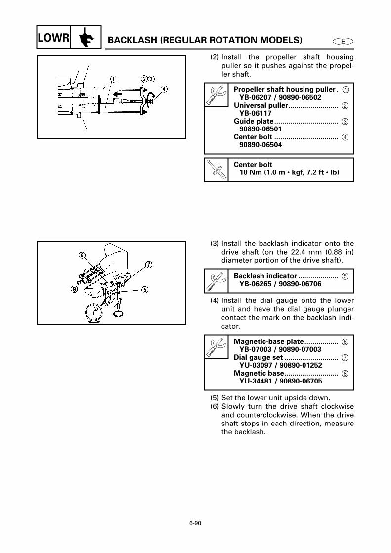
6-90
ELOWR BACKLASH (REGULAR ROTATION MODELS)
(2) Install the propeller shaft housingpuller so it pushes against the propel-ler shaft.
Propeller shaft housing puller . 1YB-06207 / 90890-06502
Universal puller......................... 2 YB-06117
Guide plate................................ 3 90890-06501
Center bolt ................................ 4 90890-06504
T R.
.
Center bolt10 Nm (1.0 m • kgf, 7.2 ft • lb)
6650
(3) Install the backlash indicator onto thedrive shaft (on the 22.4 mm (0.88 in)diameter portion of the drive shaft).
(4) Install the dial gauge onto the lowerunit and have the dial gauge plungercontact the mark on the backlash indi-cator.
(5) Set the lower unit upside down.(6) Slowly turn the drive shaft clockwise
and counterclockwise. When the driveshaft stops in each direction, measurethe backlash.
Backlash indicator .................... 5 YB-06265 / 90890-06706
Magnetic-base plate................. 6 YB-07003 / 90890-07003
Dial gauge set ........................... 7 YU-03097 / 90890-01252
Magnetic base........................... 8 YU-34481 / 90890-06705
6655

6-91
ELOWR
BACKLASH (REGULAR ROTATION MODELS)
2. Adjust:• Forward gear shim
Remove or add shim(s).
M: Measurement
Forward gear
backlashShim thickness
Less than
(150A - 225D/
C150TR - P200TR
models)
0.25 mm (0.010 in)
(150G/P150TR
models)
0.71 mm (0.028 in)
To be decreased by
(150A - 225D/
C150TR - P200TR
models)
(0.36 – M)
×
0.54
(150G/P150TR
models)
(0.86 – M)
×
0.54
More than
(150A - 225D/
C150TR - P200TR
models)
0.46 mm (0.018 in)
(150G/P150TR
models)
1.01 mm (0.040 in)
To be increased by
(150A - 225D/
C150TR - P200TR
models)
(M – 0.36)
×
0.54
(150G/P150TR
models)
(M – 0.86)
×
0.54
MEASURING THE REVERSE GEAR
BACKLASH
1. Measure:• Reverse gear backlash
Out of specification
→
Adjust.
Reverse gear backlash(150A - 225D/C150TR - P200TRmodels)
0.74 - 1.29 mm (0.029 - 0.051 in)
(150G/P150TR models)0.79 - 1.38 mm (0.031 - 0.054 in)
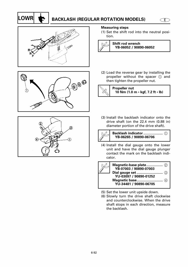
6-92
ELOWR
BACKLASH (REGULAR ROTATION MODELS)
Measuring steps
(1) Set the shift rod into the neutral posi-tion.
Shift rod wrenchYB-06052 / 90890-06052
6645
(2) Load the reverse gear by installing thepropeller without the spacer
1
andthen tighten the propeller nut.
T R.
.
Propeller nut10 Nm (1.0 m • kgf, 7.2 ft • lb)
6665
(3) Install the backlash indicator onto thedrive shaft (on the 22.4 mm (0.88 in)diameter portion of the drive shaft).
(4) Install the dial gauge onto the lowerunit and have the dial gauge plungercontact the mark on the backlash indi-cator.
(5) Set the lower unit upside down.(6) Slowly turn the drive shaft clockwise
and counterclockwise. When the driveshaft stops in each direction, measurethe backlash.
Backlash indicator ....................
1
YB-06265 / 90890-06706
Magnetic-base plate.................
2
YB-07003 / 90890-07003
Dial gauge set ...........................
3
YU-03097 / 90890-01252
Magnetic base...........................
4
YU-34481 / 90890-06705
6670

6-93
ELOWR
BACKLASH (REGULAR ROTATION MODELS)
2. Adjust:• Reverse gear shim
Remove or add shim(s).
M: Measurement
Reverse gear
backlashShim thickness
Less than
(150A - 225D/
C150TR - P200TR
models)
0.74 mm (0.029 in)
(150G/P150TR
models)
0.79 mm (0.031 in)
To be increased by
(150A - 225D/
C150TR - P200TR
models)
(1.02 – M)
×
0.54
(150G/P150TR
models)
(1.09 – M)
×
0.54
More than
(150A - 225D/
C150TR - P200TR
models)
1.29 mm (0.051 in)
(150G/P150TR
models)
1.38 mm (0.054 in)
To be decreased by
(150A - 225D/
C150TR - P200TR
models)
(M – 1.02)
×
0.54
(150G/P150TR
models)
(M – 1.09)
×
0.54

6-94
ELOWR
SHIMMING (COUNTER ROTATION MODELS) 6
NOTE:
• There is no need to select shims whenreassembling with the original case andinner parts.
• Shim calculations are required when reas-sembling with the original inner parts anda new case (the difference between theoriginal inner parts and the new case).
• Measurements and adjustments are
required when replacing the inner part(s).
6500
SHIMMING (COUNTER ROTATION MODELS)

6-95
ELOWR
SHIMMING (COUNTER ROTATION MODELS)
(FOR USA AND CANADA)
SELECTING THE PINION SHIMS
NOTE:
Find the shim thickness (T3) by selectingshims until the specified measurement (M)
is obtained with the special tool.
6505
1. Measure:• Specified measurement (M)
Out of specified value (M0)
→
Adjust.
Measuring steps
(1) Calculate the specified value (M0).
NOTE:
• “P” is the deviation of the lower casedimension from standard. It is stampedon the trim tab mounting surface of thelower case in 0.01-mm units. If the “P”mark is missing or unreadable, assume a“P” value of “0”, and check the backlashwhen the unit is assembled.
• If the “P” mark is negative (–), then sub-tract the “P” value from the measure-
ment.
Example:If “P” is “+5”, thenM0 = 1.00 + (+5)/100 mm
= 1.00 + 0.05 mm = 1.05 mm
If “P” is “–3”, thenM0 = 1.00 + (–3)/100 mm
= 1.00 – 0.03 mm = 0.97 mm
Specified value (M0) =1.00 + P/100 mm
6520
M
6510

6-96
ELOWR
SHIMMING (COUNTER ROTATION MODELS)
(FOR USA AND CANADA)
(2) Install the pinion height gauge, driveshaft, thrust bearing
1
, and shim(s)
2
.
NOTE:
If the original shim(s) is unavailable, start
with a 0.50-mm shim.
(3) Install the pinion and pinion nut.
Pinion height gaugeYB-34432-7, -11
T R.
.
Pinion nut95 Nm (9.5 m • kgf, 69 ft • lb)
6515
(4) Measure the specified measurement(M).
NOTE:
• Measure the clearance between the pin-ion height gauge and the lower surface ofthe pinion as shown.
• Perform the same measurement at threepoints on the pinion.
• Find the average of the measurements (M).
2. Adjust:• Shim thickness (T3)
Remove or add shim(s).
NOTE:
(M0) – (M) should be as close to “0” as pos-
sible.
Available shim thickness0.10, 0.12, 0.15, 0.18, 0.30, 0.40and 0.50 mm
M
6520

6-97
ELOWR
SHIMMING (COUNTER ROTATION MODELS)
(FOR USA AND CANADA)
SELECTING THE REVERSE GEAR
SHIMS
NOTE:
Find the shim thickness (T1) by selectingshims until the specified value (M0) is
obtained with the special tool.
6525
1. Measure:• Specified measurement (M)
Out of specified value (M0)
→
Adjust.
Measuring steps
(1) Calculate the specified value (M0).
NOTE:
• “F” is the deviation of the lower casedimension from standard. It is stampedon the trim tab mounting surface of thelower case in 0.01-mm units. If the “F”mark is missing or unreadable, assume an“F” value of “0”, and check the backlashwhen the unit is assembled.
• If the “F” mark is negative (–), then sub-tract the “F” value from the measure-
ment.
Example: If “F” is “+5”, thenM0 = 29.10 + (+5)/100 mm
= 29.10 + 0.05 mm= 29.15 mm
If “F” is “–3”, thenM0 = 29.10 + (–3)/100 mm
= 29.10 – 0.03 mm= 29.07 mm
Specified value (M0) =29.10 + F/100 mm
6527
6530

6-98
ELOWR
SHIMMING (COUNTER ROTATION MODELS)
(FOR USA AND CANADA)
(2) Install the roller bearing
1
, thrustbearing
2
, and shim(s)
3
.
NOTE:
If the original shim(s) is unavailable, start
with a 0.50-mm shim.
(3) Measure the specified measurement(M).
6540
2. Adjust:• Shim thickness (T1)
Remove or add shim(s).
NOTE:
(M0) – (M) should be as close to “0” as pos-
sible.
Available shim thickness0.10, 0.12, 0.15, 0.18, 0.30, 0.40and 0.50 mm
SELECTING THE FORWARD GEAR
SHIMS
NOTE:
Find the shim thickness (T2) by selectingshims until the specified value (M0) is
obtained with the special tool.
6545
1. Measure:• Specified measurement (M)
Out of specified value (M0)
→
Adjust.
Specified value (M0) =1.30 – R/100 mm
6556
M

6-99
ELOWR
SHIMMING (COUNTER ROTATION MODELS)
(FOR USA AND CANADA)
Measuring steps
(1) Calculate the specified value (M0).
NOTE:
• “R” is the deviation of the lower casedimension from standard. It is stampedon the trim tab mounting surface of thelower case in 0.01-mm units. If the “R”mark is missing or unreadable, assume an“R” value of “0”, and check the backlashwhen the unit is assembled.
• If the “R” mark is negative (–), then addthe “R” value to the measurement.
Example: If “R” is “+5”, then M0 = 1.30 – (+5)/100 mm
= 1.30 – 0.05 mm = 1.25 mm
If “R” is “–3”, then M0 = 1.30 – (–3)/100 mm
= 1.30 + 0.03 mm = 1.33 mm
6550
(2) Install the shimming gauge, bearing,thrust washer, forward gear, andshim(s).
NOTE:
• If the original shim(s) is unavailable, startwith a 0.50-mm shim.
• Turn the forward gear assembly a fewtimes until the gear and bearing are hori-zontal.
(3) Measure the specified measurement(M).
Shimming gaugeYB-34468-2
6556
M

6-100
ELOWRSHIMMING (COUNTER ROTATION MODELS)
(FOR USA AND CANADA)
2. Adjust:• Shim thickness (T2)
Remove or add shim(s).
NOTE:
(M0) – (M) should be as close to “0” as pos-sible.
SELECTING THE PROPELLER SHAFT
SHIMS
NOTE:
Find the shim thickness (T4) by selectingshims until the specified measurement isobtained with the special tool.
1. Install:• Shim(s) 1 • Thrust bearing 2 • Propeller shaft 3 • Tapered roller bearing 4
Available shim thickness0.10, 0.12, 0.15, 0.18, 0.30, 0.40and 0.50 mm
6560
6565
2. Measure:• Propeller shaft free play
Out of specification → Adjust.
3. Adjust:• Propeller shaft free play
Remove or add shim(s).
Propeller shaft free play0.30 ± 0.05 mm
Magnetic base........................... 1 YU-34481
Dial gauge set ........................... 2 YU-03097
Available shim thickness0.10, 0.12, 0.15, 0.18, 0.30, 0.40and 0.50 mm
6570

6-101
ELOWRSHIMMING (COUNTER ROTATION MODELS)
(EXCEPT FOR USA AND CANADA)
SELECTING THE PINION SHIMS
NOTE:
Select the shim thickness (T3) by using thespecified measurement(s) and the calcula-tion formula
Select:• Shim thickness (T3)
Selecting steps
(1) Measure (M3).
NOTE:
Install the bearing housing 1, thrust bear-ing 2, and washer 3.
(2) Install the pinion and pinion nut.
(3) Install the pinion height gauge.
NOTE:
After the wing nuts contact the fixing plate,tighten them another 1/4 of a turn.
(4) Measure (M4).
NOTE:
• Measure the clearance between the pin-ion height gauge and the pinion, asshown.
• Perform the same measurement at threepoints on the pinion.
• Find the average of the measurements(M4).
Digital caliper90890-06704
T R.
.
Pinion nut95 Nm (9.5 m • kgf, 69 ft • lb)
Pinion height gauge90890-06702
Digital caliper90890-06704
6575
6580
6585

6-102
ELOWRSHIMMING (COUNTER ROTATION MODELS)
(EXCEPT FOR USA AND CANADA)
(5) Calculate the pinion shim thickness(T3).
NOTE:
• “P” is the deviation of the lower casedimension from standard. It is stampedon the trim tab mounting surface of thelower case in 0.01-mm units. If the “P”mark is missing or unreadable, assume a“P” value of “0”, and check the backlashwhen the unit is assembled.
• If the “P” mark is negative (–), then addthe “P” value to the measurement.
Example:If M3 is “46.85 mm”, M4 is “32.52 mm” andP is “–5”, then T3 = 80.0 + (–5)/100 – 46.85 – 32.52 mm
= 80.0 – 0.05 – 46.85 – 32.52 mm= 0.58 mm
(6) Select the pinion shim(s) (T3).
Pinion shim thickness (T3) =80.0 + P/100 – M3 – M4
Calculated numeral
at 1/100th place Rounded
numeralMore than or less
0.00 0.02 0.00
0.02 0.05 0.02
0.05 0.08 0.05
0.08 0.10 0.08
Available shim thickness0.10, 0.12, 0.15, 0.18, 0.30, 0.40and 0.50 mm
6590

6-103
ELOWRSHIMMING (COUNTER ROTATION MODELS)
(EXCEPT FOR USA AND CANADA)
SELECTING THE REVERSE GEAR
SHIMS
NOTE:
Select the shim thickness (T1) by using thespecified measurement(s) and the calcula-tion formula.
Select:• Shim thickness (T1)
Selecting steps
(1) Measure (M1).
NOTE:
• Measure the combined thickness of theroller bearing 1 and thrust bearing 2.
• Turn the roller bearing outer race two orthree times so the rollers seat. Then, mea-sure the height of the bearing, as shown.
• Perform the same measurement at threepoints on the roller bearing outer race.
• Find the average of the measurements(M1).
Digital caliper90890-06704
6595
6605
(2) Calculate the reverse gear shim thick-ness (T1).
NOTE:
• “F” is the deviation of the lower casedimension from standard. It is stampedon the trim tab mounting surface of thelower case in 0.01-mm units. If the “F”mark is missing or unreadable, assume an“F” value of “0”, and check the backlashwhen the unit is assembled.
• If the “F” mark is negative (–), then sub-tract the “F” value from the measure-ment.
Reverse gear shim thickness (T1)(T1) = 29.1 + F/100 – M1
6610

6-104
ELOWRSHIMMING (COUNTER ROTATION MODELS)
(EXCEPT FOR USA AND CANADA)
Example: If M1 is “28.10 mm” and F is “+5”, thenT1 = 29.1 + (+5)/100 – 28.10 mm
= 29.1 + 0.05 – 28.10 mm= 1.05 mm
(3) Select the reverse gear shim(s).
Calculated numeral
at 1/100th place Rounded
numeralMore than or less
0.00 0.02 0.00
0.02 0.05 0.02
0.05 0.08 0.05
0.08 0.10 0.08
Available shim thickness0.10, 0.12, 0.15, 0.18, 0.30, 0.40and 0.50 mm
SELECTING THE FORWARD GEAR
SHIMS
NOTE:
Select the shim thickness (T2) by using thespecified measurement(s) and the calcula-tion formula.
Select:• Shim thickness (T2)
Selecting steps
(1) Measure (M2).
NOTE:
• Measure the height of the gear as shown.• Perform the same measurement at three
points on the gear.• Find the average of the measurements
(M2).
Shimming plate ........................ 1 90890-06701
Digital caliper ............................ 2 90890-06704
6615
6620

6-105
ELOWRSHIMMING (COUNTER ROTATION MODELS)
(EXCEPT FOR USA AND CANADA)
(2) Calculate the forward gear shim thick-ness (T2).
NOTE:
• “R” is the deviation of the lower casedimension from standard. It is stampedon the trim tab mounting surface of thelower case in 0.01-mm units. If the “R”mark is missing or unreadable, assume a“R” value of “0”, and check the backlashwhen the unit is assembled.
• If the “R” mark is negative (–), then sub-tract the “R” value from the measure-ment.
Example: If M2 is “30.50 mm”, R is “+2”, then T2 = 30.50 – 29.5 – (+2)/100 mm
= 30.50 – 29.5 – 0.02 mm= 0.98 mm
(3) Select the forward gear shim(s) (T2).
Forward gear shim thickness(T2) = M2 – 29.5 – R/100
Calculated numeral
at 1/100th place Rounded
numeralMore than or less
0.00 0.02 0.02
0.02 0.05 0.05
0.05 0.08 0.08
0.08 0.10 0.10
Available shim thickness0.10, 0.12, 0.15, 0.18, 0.30, 0.40and 0.50 mm
6625
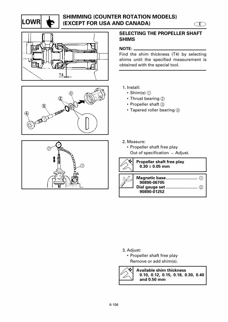
6-106
ELOWRSHIMMING (COUNTER ROTATION MODELS)
(EXCEPT FOR USA AND CANADA)
SELECTING THE PROPELLER SHAFT
SHIMS
NOTE:
Find the shim thickness (T4) by selectingshims until the specified measurement isobtained with the special tool.
6630
1. Install:• Shim(s) 1 • Thrust bearing 2 • Propeller shaft 3 • Tapered roller bearing 4
6635
2. Measure:• Propeller shaft free play
Out of specification → Adjust.
Propeller shaft free play0.30 ± 0.05 mm
Magnetic base........................... 1 90890-06705
Dial gauge set ........................... 2 90890-01252
6640
3. Adjust:• Propeller shaft free play
Remove or add shim(s).
Available shim thickness0.10, 0.12, 0.15, 0.18, 0.30, 0.40and 0.50 mm

6-107
ELOWR BACKLASH (COUNTER ROTATION MODELS)
BACKLASH (COUNTER ROTATION MODELS)6
NOTE:
• Do not install the water pump compo-nents when measuring the backlash.
• Measure both the forward and reversegear backlashes.
• If both the forward and reverse gear back-lashes are larger than specification, thepinion may be too high.
• If both the forward and reverse gear back-lashes are smaller than specification, thepinion may be too low.
MEASURING THE FORWARD GEAR
BACKLASH
1. Measure:• Forward gear backlash
Out of specification → Adjust.
Measuring steps
(1) Set the shift rod into the neutral posi-tion.
(2) Install the propeller shaft housingpuller so it pushes against the propel-ler shaft.
Forward gear backlash0.21 - 0.43 mm (0.008 - 0.017 in)
Shift rod wrenchYB-06052 / 90890-06052
Propeller shaft housing puller . 1 YB-06207 / 90890-06502
Universal puller......................... 2 YB-06117
Guide plate................................ 390890-06501
Center bolt ................................ 4 90890-06504
T R.
.
Center bolt10 Nm (1.0 m • kgf, 7.2 ft • lb)
6645
6650

6-108
ELOWR BACKLASH (COUNTER ROTATION MODELS)
(3) Install the backlash indicator onto thedrive shaft (on the 22.4 mm (0.88 in)diameter portion of the drive shaft).
(4) Install the dial gauge onto the lowerunit and have the dial gauge plungercontact the mark on the backlash indi-cator.
(5) Set the lower unit upside down.(6) Slowly turn the drive shaft clockwise
and counterclockwise. When the driveshaft stops in each direction, measurethe backlash.
2. Adjust:• Forward gear shim
Remove or add shim(s).
M: Measurement
Backlash indicator .................... 5 YB-06265 / 90890-06706
Magnetic-base plate................. 6YB-07003 / 90890-07003
Dial gauge set ........................... 7 YU-03097 / 90890-01252
Magnetic base........................... 8 YU-34481 / 90890-06705
Forward
gear backlashShim thickness
Less than
0.21 mm (0.008 in)
To be increased by
(0.32 – M) × 0.54
More than
0.43 mm (0.017 in)
To be decreased by
(M – 0.32) × 0.54
6655
MEASURING THE REVERSE GEAR
BACKLASH
1. Measure:• Reverse gear backlash
Out of specification → Adjust.
Reverse gear backlash0.97 - 1.29 mm (0.038 - 0.051 in)
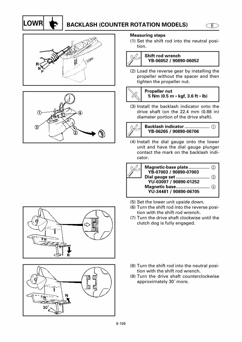
6-109
ELOWR BACKLASH (COUNTER ROTATION MODELS)
Measuring steps
(1) Set the shift rod into the neutral posi-tion.
(2) Load the reverse gear by installing thepropeller without the spacer and thentighten the propeller nut.
(3) Install the backlash indicator onto thedrive shaft (on the 22.4 mm (0.88 in)diameter portion of the drive shaft).
(4) Install the dial gauge onto the lowerunit and have the dial gauge plungercontact the mark on the backlash indi-cator.
(5) Set the lower unit upside down.(6) Turn the shift rod into the reverse posi-
tion with the shift rod wrench.(7) Turn the drive shaft clockwise until the
clutch dog is fully engaged.
Shift rod wrenchYB-06052 / 90890-06052
T R.
.
Propeller nut5 Nm (0.5 m • kgf, 3.6 ft • lb)
Backlash indicator .................... 1 YB-06265 / 90890-06706
Magnetic-base plate................. 2 YB-07003 / 90890-07003
Dial gauge set ........................... 3 YU-03097 / 90890-01252
Magnetic base........................... 4 YU-34481 / 90890-06705
6645
6710
6715
(8) Turn the shift rod into the neutral posi-tion with the shift rod wrench.
(9) Turn the drive shaft counterclockwiseapproximately 30˚ more.
6720

6-110
ELOWR BACKLASH (COUNTER ROTATION MODELS)
(10) Turn the shift rod into the reverse posi-tion with the shift rod wrench.
(11) Slowly turn the drive shaft clockwiseand counterclockwise. When the driveshaft stops in each direction, measurethe backlash.
NOTE:
When measuring the reverse gear backlash,turn the shift rod wrench slightly towardsthe reverse position.
2. Adjust:• Reverse gear shim
Remove or add shim(s).
M: Measurement
Reverse gear
backlashShim thickness
Less than
0.97 mm (0.038 in)
To be decreased by
(1.13 – M) × 0.54
More than
1.29 mm (0.051 in)
To be increased by
(M – 1.13) × 0.54
6725

6-111
ELOWR SHIMMING (DUAL PROPELLER MODELS)
SHIMMING (DUAL PROPELLER MODELS) 6
NOTE:
• There is no need to select shims whenreassembling with the original case andinner parts.
• Shim calculations are required when reas-sembling with the original inner parts anda new case (the difference between theoriginal inner parts and the new case).
• Measurements and adjustments arerequired when replacing the inner part(s).
6730
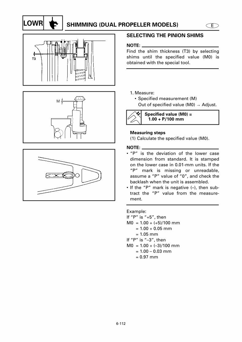
6-112
ELOWR SHIMMING (DUAL PROPELLER MODELS)
SELECTING THE PINION SHIMS
NOTE:
Find the shim thickness (T3) by selectingshims until the specified value (M0) isobtained with the special tool.
6735
1. Measure:• Specified measurement (M)
Out of specified value (M0) → Adjust.
Measuring steps
(1) Calculate the specified value (M0).
NOTE:
• “P” is the deviation of the lower casedimension from standard. It is stampedon the lower case in 0.01-mm units. If the“P” mark is missing or unreadable,assume a “P” value of “0”, and check thebacklash when the unit is assembled.
• If the “P” mark is negative (–), then sub-tract the “P” value from the measure-ment.
Example:If “P” is “+5”, thenM0 = 1.00 + (+5)/100 mm
= 1.00 + 0.05 mm = 1.05 mm
If “P” is “–3”, then M0 = 1.00 + (–3)/100 mm
= 1.00 – 0.03 mm = 0.97 mm
Specified value (M0) =1.00 + P/100 mm
6750
M
6740

6-113
ELOWR SHIMMING (DUAL PROPELLER MODELS)
(2) Install the pinion height gauge, driveshaft, thrust bearing 1, and shim(s) 2.
NOTE:
If the original shim(s) is unavailable, startwith a 0.50-mm shim.
(3) Install the pinion and pinion nut.
Pinion height gaugeYB-34432-11, -97
T R.
.
Pinion nut95 Nm (9.5 m • kgf, 68 ft • lb)
6745
(4) Measure the specified measurement(M).
NOTE:
• Measure the clearance between the pin-ion height gauge and the lower surface ofthe pinion as shown.
• Perform the same measurement at threepoints on the pinion.
• Final the average of the measurements(M).
2. Adjust:• Shim thickness (T3)
Remove or add shim(s).
NOTE:
(M0) – (M) should be as close to “0” as pos-sible.
Available shim thicknesses0.10, 0.12, 0.15, 0.18, 0.30, 0.40and 0.50 mm
M
6750

6-114
ELOWR SHIMMING (DUAL PROPELLER MODELS)
SELECTING THE FRONT GEAR SHIMS
NOTE:
Find the shim thickness (T1) by selectingshims until the specified value (M0) isobtained with the special tool.
1. Measure:• Specified measurement (M)
Out of specified value (M0) → Adjust.
Measuring steps
(1) Calculate the specified value (M0).
NOTE:
• “F” is the deviation of the lower casedimension from standard. It is stampedon the lower case in 0.01-mm units. If the“F” mark is missing or unreadable,assume an “F” value of “0”, and check thebacklash when the unit is assembled.
• If the “F” mark is negative (–), then sub-tract the “F” value from the measure-ment.
Example:If “F” is “+5”, thenM0 = 1.00 + (+5)/100 mm
= 1.00 + 0.05 mm= 1.05 mm
If “F” is “–3”, thenM0 = 1.00 + (–3)/100 mm
= 1.00 – 0.03 mm= 0.97 mm
(2) Install the shimming gauge, bearing1, and shim(s) 2.
NOTE:
If the original shim(s) is unavailable, startwith a 0.50-mm shim.
Specified value (M0) =1.00 + F/100 mm
Shimming gaugeYB-34446-1, -3, -4, -7
6755
6526
6760
6765

6-115
ELOWR SHIMMING (DUAL PROPELLER MODELS)
(3) Measure the specified measurement(M).
2. Adjust:• Shim thickness (T1)
Remove or add shim(s).
NOTE:
(M0) – (M) should be as close to “0” as pos-sible.
Available shim thickness0.10, 0.12, 0.15, 0.18, 0.30, 0.40and 0.50 mm
SELECTING THE REAR GEAR SHIMS
NOTE:
Find the shim thickness (T2) by selectingshims until the specified value (M0) isobtained with the special tool.
1. Measure:• Specified measurement (M)
Out of specified value (M0) → Adjust.
Measuring steps
(1) Calculate the specified value (M0).
NOTE:
• “R” is the deviation of the lower casedimension from standard. It is stampedon the lower case in 0.01-mm units. If the“R” mark is missing or unreadable,assume an “R” value of “0”, and checkthe backlash when the unit is assembled.
• If the “R” mark is negative (–), then addthe “R” value to the measurement.
Specified measurement (M0) =1.60 – R/100 mm
6770
6556
M
6775

6-116
ELOWR SHIMMING (DUAL PROPELLER MODELS)
Example:If “R” is “+5”, thenM0 = 1.60 – (+5)/100 mm
= 1.60 – 0.05 mm = 1.55 mm
If “R” is “–3”, thenM0 = 1.60 – (–3)/100 mm
= 1.60 + 0.03 mm = 1.63 mm
(2) Install the shimming gauge, bearing,thrust washer, rear gear, and shim(s).
NOTE:
• If the original shim(s) is unavailable, startwith a 0.50-mm shim.
• Turn the rear gear assembly a few timesuntil the gear and bearing are horizontal.
(3) Measure the specified measurement(M).
Shimming gaugeYB-34468-1
6556
M
2. Adjust:• Shim thickness (T2)
Remove or add shim(s).
NOTE:
(M0) – (M) should be as close to “0” as pos-sible.
Available shim thicknesses0.10, 0.12, 0.15, 0.18, 0.30, 0.40and 0.50 mm

6-117
ELOWR SHIMMING (DUAL PROPELLER MODELS)
SELECTING THE OUTER PROPELLER
SHAFT SHIMS
NOTE:
Find the shim thickness (T4) by selectingshims until the specified measurement isobtained with the special tool.
6785
1. Install:• Shim(s) 1 • Thrust bearing 2 • Outer propeller shaft 3 • Tapered roller bearing 4
6790
2. Measure:• Outer propeller shaft free play
Out of specification → Adjust.
Propeller shaft free play0.30 ± 0.05 mm
Magnetic base........................... 1 YU-34481
Dial gauge set ........................... 2 YU-03097
6795
3. Adjust:• Outer propeller shaft free play
Remove or add shim(s).
Available shim thickness0.10, 0.12, 0.15, 0.18, 0.30, 0.40and 0.50 mm

6-118
ELOWR BACKLASH (DUAL PROPELLER MODELS)
BACKLASH (DUAL PROPELLER MODELS) 6
NOTE:
• Do not install the water pump compo-nents when measuring the backlash.
• Measure both the forward and reversegear backlashes.
• If both the forward and reverse gear back-lashes are larger than specification, thepinion may be too high.
• If both the forward and reverse gear back-lashes are smaller than specification, thepinion may be too low.
MEASURING THE FRONT GEAR
BACKLASH
1. Measure:• Front gear backlash
Out of specification → Adjust.
Measuring steps
(1) Set the shift rod into the neutral posi-tion.
(2) Install the propeller shaft housingpuller so it pushes against the innerpropeller shaft.
Front gear backlash0.19 - 0.59 mm (0.007 - 0.023 in)
Shift rod wrenchYB-06052 / 90890-06052
Propeller shaft housing puller . 1YB-06502 / 90890-06502
Universal puller......................... 2 YB-06540 / 90890-06540
T R.
.
Universal puller10 Nm (1.0 m • kgf, 7.2 ft • lb)
6645
2
1
6807

6-119
ELOWR BACKLASH (DUAL PROPELLER MODELS)
(3) Install the backlash indicator onto thedrive shaft (on the 22.4 mm (0.88 in)diameter portion of the drive shaft a).
(4) Install the dial gauge onto the lowerunit and have the dial gauge plungercontact the mark on the backlash indi-cator.
(5) Set the lower unit upside down.(6) Slowly turn the drive shaft clockwise
and counterclockwise. When the driveshaft stops in each direction, measurethe backlash.
Backlash indicator .................... 3 YB-06265 / 90890-06706
Magnetic-base plate................. 4 YB-07003 / 90890-07003
Dial gauge set ........................... 5 YU-03097 / 90890-01252
Magnetic base........................... 6 YU-34481 / 90890-06705
6810
2. Adjust:• Front gear shim
Remove or add shim(s).
M: Measurement
Front gear
backlashShim thickness
Less than
0.19 mm
(0.007 in)
To be decreased by
(0.39 – M) × 0.50
More than
0.59 mm
(0.023 in)
To be increased by
(M – 0.39) × 0.50
Available shim thickness0.10, 0.12, 0.15, 0.18, 0.30, 0.40and 0.50 mm
6835

6-120
ELOWR BACKLASH (DUAL PROPELLER MODELS)
MEASURING THE REAR GEAR
BACKLASH
1. Measure:• Rear gear backlash
Out of specification → Adjust.
Rear gear backlash0.39 - 0.70 mm (0.015 - 0.027 in)
Measuring steps
(1) Set the shift rod into the neutral posi-tion.
Shift rod wrenchYB-06052 / 90890-06052
6645
(2) Install the propeller shaft housingpuller so it pushes against the outerpropeller shaft.
Propeller shaft housing puller . 1 YB-06502 / 90890-06502
Propeller shaft housing puller extension................................... 2
YB-06513 / 90890-06513 Universal puller......................... 3
YB-06540 / 90890-06540
T R.
.
Universal puller10 Nm (1.0 m • kgf, 7.2 ft • lb)
32 1
6842

6-121
ELOWR BACKLASH (DUAL PROPELLER MODELS)
(3) Install the backlash indicator onto thedrive shaft (on the 22.4 mm (0.88 in)diameter portion of the drive shaft a).
(4) Install the dial gauge onto the lowerunit and have the dial gauge plungercontact the mark on the backlash indi-cator.
(5) Set the lower unit upside down.(6) Slowly turn the drive shaft clockwise
and counterclockwise. When the driveshaft stops in each direction, measurethe backlash.
Backlash indicator .................... 4 YB-06265 / 90890-06706
Magnetic-base plate................. 5 YB-07003 / 90890-07003
Dial gauge set ........................... 6 YU-03097 / 90890-01252
Magnetic base........................... 7 YU-34481 / 90890-06705
6865
2. Adjust:• Rear gear backlash
Remove or add shim(s).
M: Measurement
Rear gear
backlashShim thickness
Less than
0.39 mm
(0.015 in)
To be increased by
(0.55 – M) × 0.50
More than
0.70 mm
(0.027 in)
To be decreased by
(M – 0.55) × 0.50
Available shim thickness0.10, 0.12, 0.15, 0.18, 0.30, 0.40and 0.50 mm
6870


EBRKT
CHAPTER 7
BRACKET UNIT
BOTTOM COWLING
....................................................................................... 7-1REMOVING/INSTALLING THE BOTTOM COWLING............................. 7-1DISASSEMBLING/ASSEMBLING THE BOTTOM COWLING (FOR PRE-MIX MODELS, EXCEPT FOR 225DET).................................. 7-3DISASSEMBLING/ASSEMBLING THE BOTTOM COWLING (FOR OIL INJECTION MODELS, AND 225DET)..................................... 7-5
SHIFT ROD ASSEMBLY
................................................................................. 7-8DISASSEMBLING/ASSEMBLING THE SHIFT ROD ASSEMBLY........... 7-8
UPPER CASE ASSEMBLY
............................................................................ 7-10REMOVING/INSTALLING THE UPPER CASE ASSEMBLY.................. 7-10DISASSEMBLING/ASSEMBLING THE UPPER CASE ASSEMBLY ..... 7-11
EXHAUST MANIFOLD ASSEMBLY
............................................................. 7-14DISASSEMBLING/ASSEMBLING THE EXHAUST MANIFOLD ASSEMBLY............................................................................................ 7-14
CLAMP BRACKETS
...................................................................................... 7-16REMOVING/INSTALLING THE CLAMP BRACKETS............................. 7-16
STEERING ARM
............................................................................................ 7-18REMOVING/INSTALLING THE STEERING ARM.................................. 7-18
SWIVEL BRACKET ASSEMBLY
................................................................... 7-19DISASSEMBLING/ASSEMBLING THE SWIVEL BRACKET ASSEMBLY............................................................................................ 7-19
POWER TRIM AND TILT UNIT
..................................................................... 7-21REMOVING/INSTALLING THE POWER TRIM AND TILT UNIT........... 7-21REMOVING THE POWER TRIM AND TILT UNIT ................................. 7-22BLEEDING THE POWER TRIM AND TILT UNIT ................................... 7-22

E
1 2 3 4 5 6 7 8 9
BRKT
RESERVOIR AND POWER TRIM AND TILT MOTOR
................................. 7-24REMOVING/INSTALLING THE RESERVOIR AND POWER TRIM AND TILT MOTOR................................................................................. 7-24INSPECTING THE RESERVOIR.............................................................. 7-25INSPECTING THE GEAR PUMP HOUSING FILTER ............................. 7-25INSTALLING THE POWER TRIM AND TILT MOTOR........................... 7-26FILLING THE RESERVOIR...................................................................... 7-27BLEEDING THE POWER TRIM AND TILT UNIT ................................... 7-27MEASURING THE HYDRAULIC PRESSURE ........................................ 7-29
TILT RAM ASSEMBLY AND GEAR PUMP UNIT
........................................ 7-32REMOVING/INSTALLING THE TILT RAM ASSEMBLY AND GEAR PUMP UNIT ................................................................................ 7-32REMOVING THE TILT RAM END SCREW ............................................ 7-34REMOVING THE GEAR PUMP UNIT .................................................... 7-34DISASSEMBLING THE GEAR PUMP UNIT .......................................... 7-34INSPECTING THE TILT RAM................................................................. 7-35INSPECTING THE GEAR PUMP UNIT .................................................. 7-35ASSEMBLING THE GEAR PUMP UNIT ................................................ 7-36INSTALLING THE GEAR PUMP UNIT................................................... 7-37INSTALLING THE TILT RAM ASSEMBLY ............................................ 7-37
TRIM RAM ASSEMBLIES AND FREE PISTON
........................................... 7-39REMOVING/INSTALLING THE TRIM RAM ASSEMBLIES AND FREE PISTON ........................................................................................ 7-39REMOVING THE TRIM RAM END SCREWS ........................................ 7-40REMOVING THE FREE PISTON............................................................. 7-40INSPECTING THE TRIM RAMS............................................................. 7-41INSPECTING THE FREE PISTON........................................................... 7-41INSPECTING THE TRIM RAM CYLINDERS .......................................... 7-41INSTALLING THE FREE PISTON........................................................... 7-41INSTALLING THE TRIM RAMS ............................................................. 7-42

7-1
BRKT
E
BOTTOM COWLING
BOTTOM COWLING 7
REMOVING/INSTALLING THE BOTTOM COWLING
Order Job/Part Q’ty RemarksPower unit Refer to “POWER UNIT” on page 5-4.
1 Shift rod assembly 12 Bolt 13 Holder 14 Bolt 25 Bracket 16 Battery lead 27 Hose guide 1
Continued on next page.
7010

7-2
BRKT
E
7
Å
Pre-mix models, except for 225DET
Order Job/Part Q’ty Remarks8 Power trim and tilt lead 19 Trim sensor lead 110 Bolt 411 Ground lead 112 Speedometer hose 113 Flushing hose 1 Salt water models14 Bottom cowling 1
For installation, reverse the removal procedure.
7010
BOTTOM COWLING

7-3
BRKT
E
BOTTOM COWLING
7
DISASSEMBLING/ASSEMBLING THE BOTTOM COWLING
(FOR PRE-MIX MODELS, EXCEPT FOR 225DET)
Order Job/Part Q’ty Remarks1 Bolt 32 Clamp lever 33 Bushing 64 Hook 35 Wave washer 36 Pilot water hose 17 Pilot water outlet 18 Cable holder 29 Bolt 2
Continued on next page.
7020

7-4
BRKT
E
BOTTOM COWLING
7
Order Job/Part Q’ty Remarks10 Fuel hose holder 211 Bolt 112 Fuel hose holder 113 Bolt 114 Ground lead 115 Grommet 416 Collar 417 Bottom cowling 1
For assembly, reverse the disassembly procedure.
7020

7-5
BRKT
E
7
DISASSEMBLING/ASSEMBLING THE BOTTOM COWLING
(FOR OIL INJECTION MODELS, AND 225DET)
Order Job/Part Q’ty Remarks1 Bolt 32 Lower spring holder 33 Spring 34 Bolt 35 Upper spring holder 36 Wave washer 37 Set pin 38 Bushing 69 Clamp lever 3
Continued on next page.
7030
BOTTOM COWLING

7-6
BRKT
E
7
Order Job/Part Q’ty Remarks10 Pilot water hose 111 Pilot water outlet 112 Wire harness clamp 113 Bolt 114 Cable holder 115 Choke link guide 116 Bolt 117 Cable guide 118 Bolt 2
Continued on next page.
7030
BOTTOM COWLING

7-7
BRKT
E
7
Order Job/Part Q’ty Remarks19 Trailer switch holder 120 Trailer switch 121 Bolt 122 Ground lead 123 Grommet 424 Collar 425 Bottom cowling 1
For assembly, reverse the disassembly procedure.
7030
BOTTOM COWLING

7-8
BRKT
E
SHIFT ROD ASSEMBLY
SHIFT ROD ASSEMBLY 7
DISASSEMBLING/ASSEMBLING THE SHIFT ROD ASSEMBLY
Order Job/Part Q’ty Remarks1 Screw 12 Spring 13 Ball 14 Clip 15 Shift rod lever 16 Clip 17 Bushing 1
Continued on next page.
7040
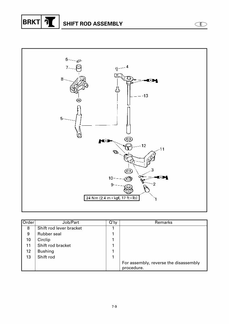
7-9
BRKT
E
SHIFT ROD ASSEMBLY
7
Order Job/Part Q’ty Remarks8 Shift rod lever bracket 19 Rubber seal 110 Circlip 111 Shift rod bracket 112 Bushing 113 Shift rod 1
For assembly, reverse the disassembly procedure.
7040

7-10
BRKT
E
UPPER CASE ASSEMBLY
UPPER CASE ASSEMBLY 7
REMOVING/INSTALLING THE UPPER CASE ASSEMBLY
Order Job/Part Q’ty RemarksLower unit Refer to “LOWER UNIT (REGULAR
ROTATION MODELS)” on page 6-1.Bottom cowling Refer to “BOTTOM COWLING” on
page 7-1.1 Bolt 12 Ground lead 1 (upper case-to-swivel bracket)3 Screw 24 Lower mount cover 25 Cap nut 26 Self-locking nut 27 Upper case assembly 18 Rubber seal 1
For installation, reverse the removal procedure.
7050

7-11
BRKT
E
UPPER CASE ASSEMBLY
7
DISASSEMBLING/ASSEMBLING THE UPPER CASE ASSEMBLY
Order Job/Part Q’ty Remarks1 Bolt 32 Upper mount bracket 13 Upper mount 24 Bolt 25 Bolt 46 Lower mount bracket 27 Spring 28 Lower mount 2
Continued on next page.
7060

7-12
BRKT
E
UPPER CASE ASSEMBLY
7
Order Job/Part Q’ty Remarks9 Ground lead 110 Bolt 211 Bolt 212 Bolt 213 Muffler assembly 114 Rubber seal 115 Muffler 1 X transom models16 Rubber seal 1 X transom models17 Rubber seal 1 X transom models
Continued on next page.
7060

7-13
BRKT
E
7
Order Job/Part Q’ty Remarks18 Upper case 119 Dowel pin 220 Circlip 1 X transom models21 Bushing 1 X transom models
For assembly, reverse the disassembly procedure.
7060
UPPER CASE ASSEMBLY

7-14
BRKT
E
EXHAUST MANIFOLD ASSEMBLY 7
DISASSEMBLING/ASSEMBLING THE EXHAUST MANIFOLD ASSEMBLY
Order Job/Part Q’ty Remarks1 Bolt 52 Muffler 13 Gasket 14 Water tube 15 Water seal 16 Bolt 47 Exhaust manifold 18 Gasket 19 Bolt 4
Continued on next page.
7070
Not reusable
Not reusable
EXHAUST MANIFOLD ASSEMBLY

7-15
BRKT
E
EXHAUST MANIFOLD ASSEMBLY
7
Order Job/Part Q’ty Remarks10 Lower exhaust manifold guide 111 Gasket 112 Upper exhaust manifold guide 113 Plastic locking tie 1 Salt water models14 Flushing hose 1 Salt water models15 Plastic locking tie 116 Cooling water hose 1
For assembly, reverse the disassembly procedure.
7070
Not reusable
Not reusable
Not reusable

7-16
BRKT
E
CLAMP BRACKETS 7
REMOVING/INSTALLING THE CLAMP BRACKETS
Order Job/Part Q’ty RemarksUpper case assembly Refer to “UPPER CASE ASSEMBLY” on
page 7-10.1 Rubber cap 32 Grease nipple 33 Ground lead 14 Bolt 45 Ground lead 16 Anode bracket 27 Anode 18 Trim sensor 1
Continued on next page.
7080
CLAMP BRACKETS

7-17
BRKT
E
7
Order Job/Part Q’ty Remarks9 Self-locking nut 110 Bolt 211 Clamp bracket bolt 112 Starboard clamp bracket 113 Port clamp bracket 114 Bushing 215 Swivel bracket assembly 1
For installation, reverse the removal procedure.
7080
CLAMP BRACKETS
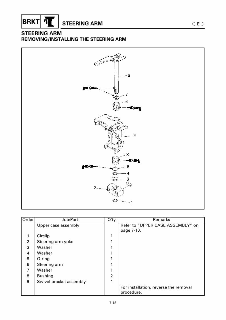
7-18
BRKT
E
STEERING ARM
STEERING ARM 7
REMOVING/INSTALLING THE STEERING ARM
Order Job/Part Q’ty RemarksUpper case assembly Refer to “UPPER CASE ASSEMBLY” on
page 7-10.1 Circlip 12 Steering arm yoke 13 Washer 14 Washer 15 O-ring 16 Steering arm 17 Washer 18 Bushing 29 Swivel bracket assembly 1
For installation, reverse the removal procedure.
7090

7-19
BRKT
E
SWIVEL BRACKET ASSEMBLY
SWIVEL BRACKET ASSEMBLY 7
DISASSEMBLING/ASSEMBLING THE SWIVEL BRACKET ASSEMBLY
Order Job/Part Q’ty RemarksSteering arm Refer to “STEERING ARM” on page 7-18.
1 Nut 22 Trim stopper 23 Bolt 14 Spring holder 15 Spring 16 Pin 2
Continued on next page.
7100

7-20
BRKT
E
7
Order Job/Part Q’ty Remarks7 Starboard tilt stop lever 18 Port tilt stop lever 19 Bushing 210 Bushing 211 Tilt stop lever joint assembly 1
For assembly, reverse the disassembly procedure.
7100
SWIVEL BRACKET ASSEMBLY
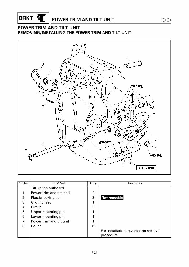
7-21
BRKT
E
POWER TRIM AND TILT UNIT
POWER TRIM AND TILT UNIT 7
REMOVING/INSTALLING THE POWER TRIM AND TILT UNIT
Order Job/Part Q’ty RemarksTilt up the outboard
1 Power trim and tilt lead 22 Plastic locking tie 33 Ground lead 14 Circlip 35 Upper mounting pin 16 Lower mounting pin 17 Power trim and tilt unit 18 Collar 6
For installation, reverse the removal procedure.
7110
Not reusable

7-22
EBRKT
POWER TRIM AND TILT UNIT
REMOVING THE POWER TRIM AND
TILT UNIT
WARNING
After tilting up the outboard, be sure to
support it with the tilt stop levers.
Otherwise, the outboard could suddenly
lower if the power trim and tilt unit should
lose fluid pressure.
NOTE:
Tilt up the outboard and then turn the tilt
stop levers
1
to support it.
Remove:• Power trim and tilt unit
NOTE:
Slightly lower the tilt ram assembly and
then remove the power trim and tilt unit.
7120
BLEEDING THE POWER TRIM AND
TILT UNIT
NOTE:
Install the power trim and tilt unit onto the
outboard before bleeding.
Bleed:• Air bubbles
(from the power trim and tilt unit)
Bleeding steps
(1) Connect the battery leads to the bat-tery.
(2) Loosen the manual valve
1
by turningit counterclockwise until it stops.
7130

7-23
EBRKT
POWER TRIM AND TILT UNIT
(3) Tilt up the outboard fully, then releaseit, and let it lower by its own weight.
(4) Tighten the manual valve by turning itclockwise.
(5) Let the power trim and tilt fluid settlefor about 5 minutes.
(6) Push and hold the power trim and tiltswitch in the up position until the out-board is fully tilted up.
(7) Turn the tilt stop levers to support theoutboard. Then, let the power trim andtilt fluid settle for about 5 minutes.
(8) Remove the reservoir cap
2
and checkthat fluid is up to the brim as shown.Add fluid if the level is below the brim.
(9) Install the power trim and tilt reservoircap.
(10) Repeat the above steps two or threetimes until the power trim and tilt fluidis at the correct level.
7140
7150

7-24
BRKT
E
RESERVOIR AND POWER TRIM AND TILT MOTOR
RESERVOIR AND POWER TRIM AND TILT MOTOR 7
REMOVING/INSTALLING THE RESERVOIR AND POWER TRIM AND TILT MOTOR
Order Job/Part Q’ty RemarksPower trim and tilt unit Refer to “POWER TRIM AND TILT UNIT”
on page 7-21.1 Reservoir cap 12 Bolt 33 Reservoir 14 Bolt 45 Power trim and tilt motor 16 O-ring 17 Drive pin 18 Gear pump housing filter 1
For installation, reverse the removal procedure.
7160

7-25
EBRKT
RESERVOIR AND POWER TRIM AND TILT MOTOR
WARNING
• To prevent the hydraulic fluid from spurt-
ing out due to internal pressure, the out-
board should be kept fully tilted up (the
tilt rod at full length).
• After removing the power trim and tilt
motor or reservoir, do not push the tilt
ram down. This may cause hydraulic fluid
to spurt out from the port.
CAUTION:
Do not wipe hydraulic system components
with rags, paper, tissues, or the like, as
fibers from such material will cause mal-
functions if they enter the system.
INSPECTING THE RESERVOIR
1. Drain:• Power trim and tilt fluid
2. Inspect:• Reservoir
Cracks/damage/leaks
→
Replace.
INSPECTING THE GEAR PUMP
HOUSING FILTER
Inspect:• Gear pump housing filter
Damage/tears
→
Replace.Foreign matter
→
Clean.
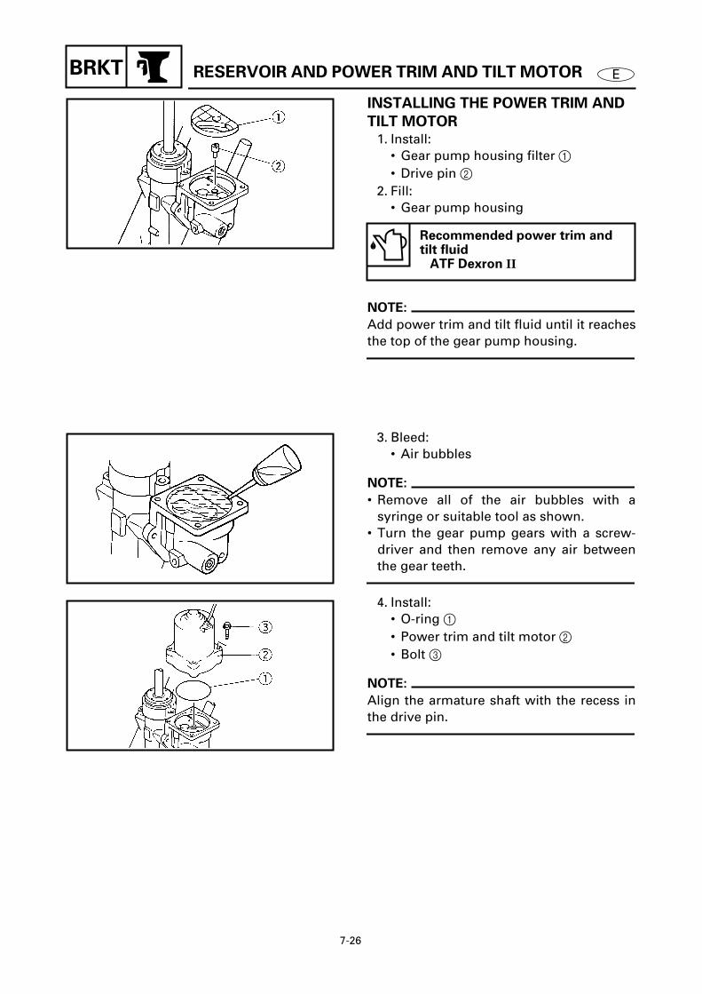
7-26
EBRKT
RESERVOIR AND POWER TRIM AND TILT MOTOR
INSTALLING THE POWER TRIM AND
TILT MOTOR
1. Install:• Gear pump housing filter
1
• Drive pin
2
2. Fill:
• Gear pump housing
NOTE:
Add power trim and tilt fluid until it reaches
the top of the gear pump housing.
Recommended power trim and tilt fluid
ATF Dexron
II
7170
3. Bleed:• Air bubbles
NOTE:
• Remove all of the air bubbles with asyringe or suitable tool as shown.
• Turn the gear pump gears with a screw-driver and then remove any air between
the gear teeth.
4. Install:• O-ring
1
• Power trim and tilt motor
2
• Bolt
3
NOTE:
Align the armature shaft with the recess in
the drive pin.
7180
7190

7-27
EBRKT
RESERVOIR AND POWER TRIM AND TILT MOTOR
FILLING THE RESERVOIR
WARNING
To prevent the hydraulic fluid from spurt-
ing out due to internal pressure, the tilt
ram should be kept at full length.
1. Fill:• Reservoir
2. Inspect:• Power trim and tilt fluid level
Level is low
→
Add power trim and tiltfluid to the proper level.
Recommended power trim and tilt fluid
ATF Dexron
II
7200
BLEEDING THE POWER TRIM AND
TILT UNIT
NOTE:
This bleeding must be done before install-ing the power trim and tilt unit onto the out-
board.
1. Bleed:• Air bubbles
(from the power trim and tilt unit)
Bleeding steps
(1) Set the power trim and tilt unit upright.(2) Connect the leads of the power trim
and tilt on the battery terminals untilthe trim and tilt ram assemblies arefully compressed.
NOTE:
If the rams will not go down, refer to the fol-lowing.A. Connect the leads of the power trim and
tilt on the battery terminals until the trimand tilt ram assemblies are fullyextended. Then, reverse the leads on thebattery terminals until the trim and tiltram assemblies are fully compressed.
7210
7220
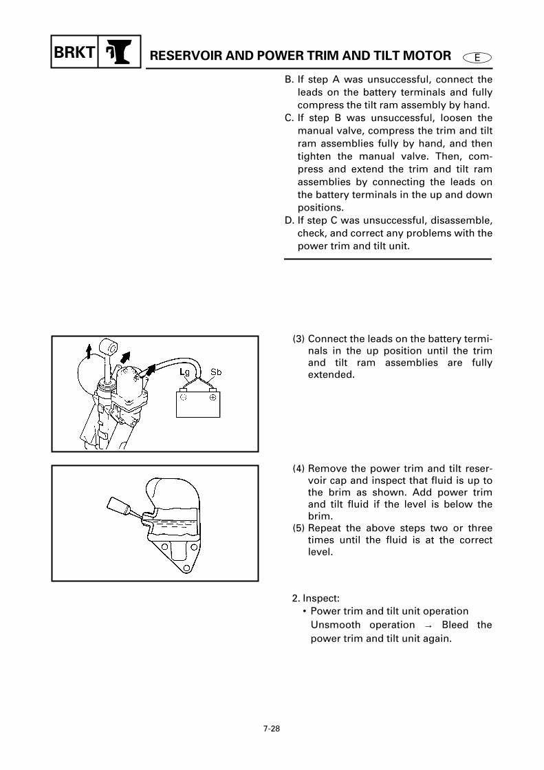
7-28
EBRKT
RESERVOIR AND POWER TRIM AND TILT MOTOR
B. If step A was unsuccessful, connect theleads on the battery terminals and fullycompress the tilt ram assembly by hand.
C. If step B was unsuccessful, loosen themanual valve, compress the trim and tiltram assemblies fully by hand, and thentighten the manual valve. Then, com-press and extend the trim and tilt ramassemblies by connecting the leads onthe battery terminals in the up and downpositions.
D. If step C was unsuccessful, disassemble,check, and correct any problems with the
power trim and tilt unit.
(3) Connect the leads on the battery termi-nals in the up position until the trimand tilt ram assemblies are fullyextended.
7220
(4) Remove the power trim and tilt reser-voir cap and inspect that fluid is up tothe brim as shown. Add power trimand tilt fluid if the level is below thebrim.
(5) Repeat the above steps two or threetimes until the fluid is at the correctlevel.
7230
2. Inspect:• Power trim and tilt unit operation
Unsmooth operation
→
Bleed thepower trim and tilt unit again.
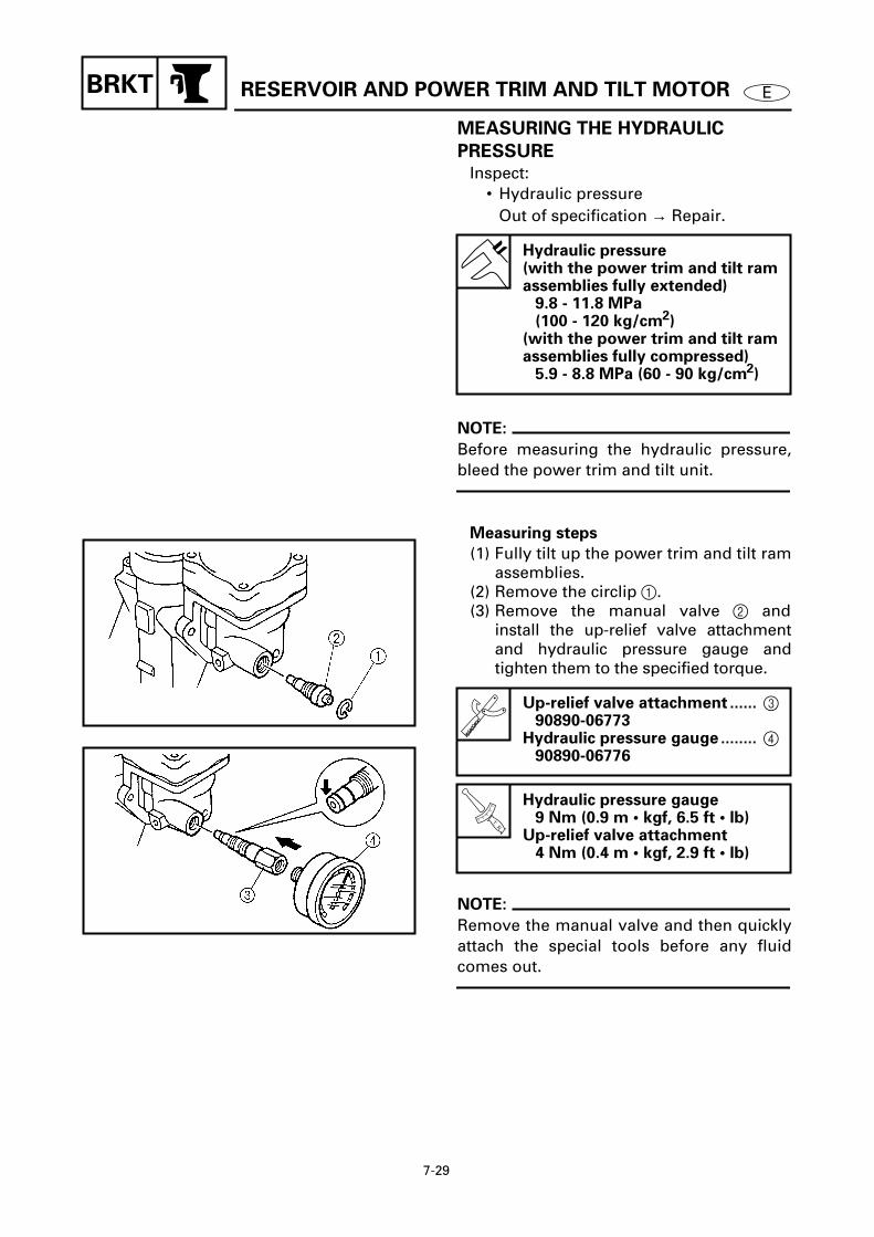
7-29
EBRKT
RESERVOIR AND POWER TRIM AND TILT MOTOR
MEASURING THE HYDRAULIC
PRESSURE
Inspect:• Hydraulic pressure
Out of specification
→
Repair.
NOTE:
Before measuring the hydraulic pressure,
bleed the power trim and tilt unit.
Measuring steps
(1) Fully tilt up the power trim and tilt ramassemblies.
(2) Remove the circlip
1
.(3) Remove the manual valve
2
andinstall the up-relief valve attachmentand hydraulic pressure gauge andtighten them to the specified torque.
NOTE:
Remove the manual valve and then quicklyattach the special tools before any fluid
comes out.
Hydraulic pressure(with the power trim and tilt ram assemblies fully extended)
9.8 - 11.8 MPa (100 - 120 kg/cm
2
)(with the power trim and tilt ram assemblies fully compressed)
5.9 - 8.8 MPa (60 - 90 kg/cm
2
)
Up-relief valve attachment ......
3
90890-06773
Hydraulic pressure gauge ........
4
90890-06776
T R.
.
Hydraulic pressure gauge9 Nm (0.9 m • kgf, 6.5 ft • lb)
Up-relief valve attachment4 Nm (0.4 m • kgf, 2.9 ft • lb)
7240
7250

7-30
EBRKT RESERVOIR AND POWER TRIM AND TILT MOTOR
(4) Connect the leads on the battery termi-nals in the down position until thepower trim and tilt ram assemblies arefully compressed.
(5) Connect the leads on the battery termi-nals in the up position until the powertrim and tilt ram assemblies are fullyextended. Then, measure the hydraulicpressure.
Hydraulic pressure(with the power trim and tilt ram assemblies fully extended)
9.8 - 11.8 MPa (100 - 120 kg/cm2)
7210
7220
(6) After measuring the hydraulic pres-sure, remove the special tools andquickly attach the down-relief valveattachment.
(7) Remove the reservoir cap and checkthat fluid is up to the brim as shown.Add fluid if the level is below the brim.
(8) Install the reservoir cap.(9) Connect the leads on the battery termi-
nals in the down position until thepower trim and tilt ram assemblies arefully compressed. Then, measure thehydraulic pressure.
Hydraulic pressure gauge ........ 4 90890-06776
Down-relief valve attachment. 5 90890-06774
T R.
.
Hydraulic pressure gauge9 Nm (0.9 m • kgf, 6.5 ft • lb)
Down-relief valve attachment4 Nm (0.4 m • kgf, 2.9 ft • lb)
Hydraulic pressure(with the power trim and tilt ram assemblies fully compressed)
5.9 - 8.8 MPa (60 - 90 kg/cm2)
7260
7270

7-31
EBRKT RESERVOIR AND POWER TRIM AND TILT MOTOR
(10) After measuring the hydraulic pres-sure, connect the leads on the batteryterminals in the up position until thepower trim and tilt ram assemblies arefully extended.
(11) Remove the special tools.(12) Install the manual valve and circlip.
NOTE:
After measuring the hydraulic pressure,bleed the power trim and tilt unit.
7280
7220

7-32
BRKT ETILT RAM ASSEMBLY AND GEAR PUMP UNIT
TILT RAM ASSEMBLY AND GEAR PUMP UNIT 7REMOVING/INSTALLING THE TILT RAM ASSEMBLY AND GEAR PUMP UNIT
Order Job/Part Q’ty RemarksReservoir and power trim and tilt motor
Refer to “RESERVOIR AND POWER TRIM AND TILT MOTOR” on page 7-24.
1 Manual valve 12 Tilt ram end screw 13 Tilt ram assembly 14 O-ring 25 Bolt 36 Gear pump unit 1
Continued on next page.
7290

7-33
BRKT ETILT RAM ASSEMBLY AND GEAR PUMP UNIT
7
Order Job/Part Q’ty Remarks7 Check valve assembly 18 Gear pump 19 Shuttle valve 210 Check valve 211 Up-relief valve assembly 112 Down-relief valve assembly 1
For installation, reverse the removal procedure.
7290
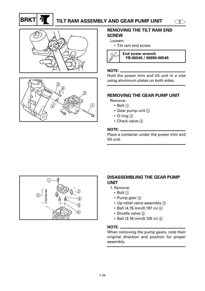
7-34
EBRKT TILT RAM ASSEMBLY AND GEAR PUMP UNIT
REMOVING THE TILT RAM END
SCREW
Loosen:• Tilt ram end screw
NOTE:
Hold the power trim and tilt unit in a viseusing aluminum plates on both sides.
REMOVING THE GEAR PUMP UNIT
Remove:• Bolt 1 • Gear pump unit 2 • O-ring 3 • Check valve 4
NOTE:
Place a container under the power trim andtilt unit.
End screw wrenchYB-06548 / 90890-06548
7300
7310
DISASSEMBLING THE GEAR PUMP
UNIT
1. Remove:• Bolt 1 • Pump gear 2 • Up-relief valve assembly 3 • Ball (4.76 mm/0.187 in) 4 • Shuttle valve 5 • Ball (3.18 mm/0.125 in) 6
NOTE:
When removing the pump gears, note theiroriginal direction and position for properassembly.
7320

7-35
EBRKT TILT RAM ASSEMBLY AND GEAR PUMP UNIT
2. Remove:• Check valves 1 and 2
NOTE:
To remove the check valves, cover the gearpump housing with a clean cloth and thenblow compressed air through holes a
and b.
7330
INSPECTING THE TILT RAM
Inspect:• Tilt ram
Excessive scratches → Replace.Bends/excessive corrosion → Replace.Rust → Polish.(with 400 - 600 grit sandpaper)
INSPECTING THE GEAR PUMP UNIT
Inspect:• Shuttle valves 1 • Check valve assemblies 2
Clogs/damage/wear → Replace.• Pump gears 3
Damage/wear → Replace the gearpump unit.
• Up-relief valve assembly 4 • Down-relief valve assembly 5
Damage/wear → Replace the gearpump unit.
• Balls 6 Damage/wear → Replace.
7335

7-36
EBRKT TILT RAM ASSEMBLY AND GEAR PUMP UNIT
ASSEMBLING THE GEAR PUMP UNIT
CAUTION:
Install all components in their original
direction and position for proper assembly
and operation.
1. Install:• Balls (3.18 mm/0.125 in) 1 • Shuttle valves 2
NOTE:
Apply grease to the balls to prevent themfrom falling out of the gear pump.
7340
2. Install:• O-ring 1 • Ball (3.18 mm/0.125 in) 2 • Up-relief valve pin 3 • Spring 4 • Up-relief valve 5 • Up-relief valve assembly 6
7350
3. Install:• O-rings 1 • Check valves 2 • Balls (4.76 mm/0.187 in) 3 • Pump gears 4
4. Install:• Gear pump 1 • Bolt 2 • Filter 3 • O-ring 4 • Down-relief valve 5 • Filter 6
NOTE:
Tighten the bolts evenly and make sure thepump gears turn smoothly.
7360
7370
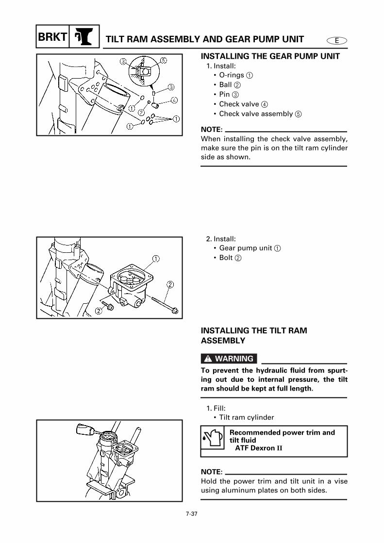
7-37
EBRKT TILT RAM ASSEMBLY AND GEAR PUMP UNIT
INSTALLING THE GEAR PUMP UNIT
1. Install:• O-rings 1 • Ball 2 • Pin 3 • Check valve 4 • Check valve assembly 5
NOTE:
When installing the check valve assembly,make sure the pin is on the tilt ram cylinderside as shown.
7380
2. Install:• Gear pump unit 1 • Bolt 2
7390
INSTALLING THE TILT RAM
ASSEMBLY
WARNING
To prevent the hydraulic fluid from spurt-
ing out due to internal pressure, the tilt
ram should be kept at full length.
1. Fill:• Tilt ram cylinder
NOTE:
Hold the power trim and tilt unit in a viseusing aluminum plates on both sides.
Recommended power trim and tilt fluid
ATF Dexron II
7400

7-38
EBRKT TILT RAM ASSEMBLY AND GEAR PUMP UNIT
2. Fill:• Gear pump housing
NOTE:
Add power trim and tilt fluid through thehole a until the fluid level is to the top ofthe gear pump unit.
Recommended power trim and tilt fluid
ATF Dexron II
7410
3. Install:• Tilt ram assembly
NOTE:
Place the tilt ram end screw at the bottomof the tilt ram and install the tilt ram assem-bly into the tilt ram cylinder.
7420
4. Tighten:• Tilt ram end screw
End screw wrenchYB-06548 / 90890-06548
T R.
.
Tilt ram end screw130 Nm (13 m • kgf, 94 ft • lb)
7430

7-39
BRKT ETRIM RAM ASSEMBLIES AND FREE PISTON
TRIM RAM ASSEMBLIES AND FREE PISTON 7REMOVING/INSTALLING THE TRIM RAM ASSEMBLIES AND FREE PISTON
Order Job/Part Q’ty RemarksTilt ram assembly and gear pump unit
Refer to “TILT RAM ASSEMBLY AND GEAR PUMP UNIT” on page 7-32.
1 Trim ram end screw 22 Trim ram 23 O-ring 24 Seal ring 25 Free piston 16 O-ring 17 Piston ring 1
For installation, reverse the removal procedure.
7440
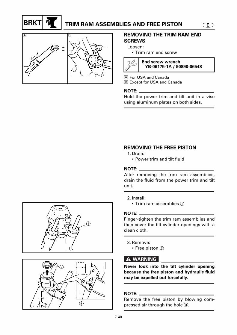
7-40
EBRKT TRIM RAM ASSEMBLIES AND FREE PISTON
REMOVING THE TRIM RAM END
SCREWS
Loosen:• Trim ram end screw
Å For USA and Canadaı Except for USA and Canada
NOTE:
Hold the power trim and tilt unit in a viseusing aluminum plates on both sides.
End screw wrenchYB-06175-1A / 90890-06548
Å ı
7450
REMOVING THE FREE PISTON
1. Drain:• Power trim and tilt fluid
NOTE:
After removing the trim ram assemblies,drain the fluid from the power trim and tiltunit.
2. Install:• Trim ram assemblies 1
NOTE:
Finger-tighten the trim ram assemblies andthen cover the tilt cylinder openings with aclean cloth.
3. Remove:• Free piston 2
WARNING
Never look into the tilt cylinder opening
because the free piston and hydraulic fluid
may be expelled out forcefully.
NOTE:
Remove the free piston by blowing com-pressed air through the hole a.
7460
7470

7-41
EBRKT TRIM RAM ASSEMBLIES AND FREE PISTON
INSPECTING THE TRIM RAMS
Inspect:• Trim ram
Excessive scratches → Replace.Bends/excessive corrosion → Replace.Rust → Polish.(with 400 - 600 grit sandpaper)
INSPECTING THE FREE PISTON
Inspect:• Free piston
Excessive scratches → Replace.
INSPECTING THE TRIM RAM
CYLINDERS
Inspect:• Trim ram cylinder
Cracks/excessive scratches → Replace the power trim and tilt unit.
INSTALLING THE FREE PISTON
1. Fill:• Fluid passages
NOTE:
• Hold the power trim and tilt unit in a viseusing aluminum plates on both sides.
• Add power trim and tilt fluid through thehole a.
Recommended power trim and tilt fluid
ATF Dexron II Quantity
30 cm3 (1.0 US oz, 1.1 lmp oz)
7480

7-42
EBRKT TRIM RAM ASSEMBLIES AND FREE PISTON
2. Install:• Piston ring 1 • O-ring 2 • Free piston 3
NOTE:
Push the free piston into the tilt ram cylin-der until it bottoms out.
7490
INSTALLING THE TRIM RAMS
WARNING
Do not push the trim rams down while
installing them into the trim ram cylinders.
Otherwise, the hydraulic fluid may spurt
out from the unit.
1. Fill:• Trim ram cylinders
NOTE:
Hold the power trim and tilt unit in a viseusing aluminum plates on both sides.
Recommended power trim and tilt fluid
ATF Dexron II
7500
2. Fill:• Fluid passages
NOTE:
Add power trim and tilt fluid through holesa, b and c until all of the passages arefilled.
Recommended power trim and tilt fluid
ATF Dexron II
7510

7-43
EBRKT TRIM RAM ASSEMBLIES AND FREE PISTON
3. Install:• Trim ram assemblies 1
NOTE:
Place each trim ram end screw at the bot-tom of each trim ram and install them intothe trim ram cylinders.
7520
4. Tighten:• Trim ram end screw
Å For USA and Canadaı Except for USA and Canada
End screw wrenchYB-06175-1A / 90890-06548
T R.
.
Trim ram end screw80 Nm (8.0 m • kgf, 58 ft • lb)
Å ı
7530


E– +
ELEC
CHAPTER 8
ELECTRICAL SYSTEMS
ELECTRICAL COMPONENTS
(OIL INJECTION AND 225DET MODELS)
.................................................... 8-1(Port view) ................................................................................................ 8-1(Starboard view) ...................................................................................... 8-2(Aft view) .................................................................................................. 8-3
ELECTRICAL COMPONENTS
(PRE-MIX EXCEPT FOR 225DET MODELS)
................................................. 8-4(Port view) ................................................................................................ 8-4(Starboard view) ...................................................................................... 8-5(Aft view) .................................................................................................. 8-6
ELECTRICAL COMPONENTS ANALYSIS
..................................................... 8-7DIGITAL CIRCUIT TESTER....................................................................... 8-7MEASURING THE PEAK VOLTAGE........................................................ 8-7PEAK VOLTAGE ADAPTOR..................................................................... 8-7MEASURING A LOW RESISTANCE........................................................ 8-8
IGNITION SYSTEM (OIL INJECTION AND 225DET MODELS)
.................... 8-9
IGNITION SYSTEM (PRE-MIX EXCEPT FOR 225DET MODELS)
............... 8-10INSPECTING THE IGNITION SPARK GAP............................................ 8-11MEASURING THE IGNITION SYSTEM PEAK VOLTAGE .................... 8-12INSPECTING THE SPARK PLUG CAPS ................................................ 8-15
IGNITION CONTROL SYSTEM
(OIL INJECTION AND 225DET MODELS)
.................................................. 8-16
IGNITION CONTROL SYSTEM
(PRE-MIX EXCEPT FOR 225DET MODELS)
............................................... 8-17MEASURING THE CRANK POSITION SENSOR OUTPUT PEAK VOLTAGE .................................................................................... 8-18MEASURING THE ENGINE COOLING WATER TEMPERATURE SENSOR RESISTANCE......................................................................... 8-18INSPECTING THE THERMO SWITCH CONTINUITY............................ 8-19INSPECTING THE OIL LEVEL SENSOR CONTINUITY......................... 8-19INSPECTING THE EMERGENCY SWITCH............................................ 8-20

E
1 2 3 4 5 6 7 8 9
– +ELEC
STARTING SYSTEM
..................................................................................... 8-21INSPECTING THE BATTERY ................................................................. 8-22INSPECTING THE FUSES...................................................................... 8-22INSPECTING THE WIRE HARNESS CONTINUITY............................... 8-22INSPECTING THE WIRE CONNECTIONS............................................. 8-22INSPECTING THE STARTER RELAY..................................................... 8-23MEASURING THE FUEL ENRICHMENT VALVE................................... 8-23
STARTER MOTOR
........................................................................................ 8-24DISASSEMBLING/ASSEMBLING THE STARTER MOTOR.................. 8-24REMOVING THE STARTER MOTOR PINION ....................................... 8-27INSPECTING THE STARTER MOTOR PINION ..................................... 8-27INSPECTING THE ARMATURE ............................................................. 8-27MEASURING THE BRUSHES................................................................ 8-28
CHARGING SYSTEM
.................................................................................... 8-30INSPECTING THE RECTIFIER/REGULATOR......................................... 8-31MEASURING THE LIGHTING COIL OUTPUT PEAK VOLTAGE .......... 8-32INSPECTING THE FUSES...................................................................... 8-32INSPECTING THE BATTERY ................................................................. 8-32
POWER TRIM AND TILT SYSTEM
.............................................................. 8-33INSPECTING THE FUSES...................................................................... 8-34INSPECTING THE BATTERY ................................................................. 8-34INSPECTING THE POWER TRIM AND TILT RELAY............................. 8-34INSPECTING THE TRAILER SWITCH CONTINUITY ............................ 8-35MEASURING THE TRIM SENSOR RESISTANCE................................. 8-36
POWER TRIM AND TILT MOTOR
................................................................ 8-37DISASSEMBLING/ASSEMBLING THE POWER TRIM AND TILT MOTOR.......................................................................................... 8-37REMOVING THE STATOR ..................................................................... 8-39REMOVING THE BRUSH ....................................................................... 8-39INSPECTING THE BRUSH ..................................................................... 8-39INSPECTING THE ARMATURE ............................................................. 8-40INSTALLING THE BRUSH ..................................................................... 8-41INSTALLING THE ARMATURE ............................................................. 8-41INSTALLING THE STATOR ................................................................... 8-41

8-1
– +ELEC
E
ELECTRICAL COMPONENTS
(OIL INJECTION AND 225DET MODELS)
ELECTRICAL COMPONENTS (OIL INJECTION AND 225DET MODELS) 8
(Port view) 8
8010
1
Oil level sensor
2
Starter motor
3
Power trim and tilt relay
4
Starter relay
5
Trailer switch
6
Fuse (30A)
7
Fuse (20A)
Å
To trim meter
ı
To battery
Ç
To CDI unit
Î
To CDI unit and 10P cou-pler
‰
To power trim and tilt motor
Ï
To trim sensor
B : BlackBr : BrownG : GreenL : BlueLg : Light greenR : RedSb : Sky blue

8-2
– +ELEC
E
ELECTRICAL COMPONENTS
(OIL INJECTION AND 225DET MODELS)
(Starboard view) 8
8020
1
Charge coil lead
2
Lighting coil lead
3
Pulser coil lead
4
Fuel enrichment valve
5
Terminal (for USA)
6
Fuse (30A)
7
Rectifier/regulator
8
Thermo switch
9
Fuel hose
0
Oil hose
A
Shift cable
B
Throttle cable
C
Speedometer hose
Å
To trim sensor
ı
To relay assembly
Ç
To battery
Î
To trim meter and tachometer
‰
To remote oil tank
Ï
To remote control
Ì
To CDI unit
Ó
To CDI unit
È
To thermo switch and emergency switch
B : BlackG : GreenL : BlueP : PinkR : RedGy/B : Gray/black

8-3
– +ELEC
E
ELECTRICAL COMPONENTS
(OIL INJECTION AND 225DET MODELS)
(Aft view) 8
8030
1
Thermo switch
2
Ignition coil
3
Emergency switch
4
Crank position sensor
5
CDI unit
6
Engine cooling water temperature sensor
Å
To charge coil
ı
To wire harness
Ç
To 10P coupler
Î
To pulser coil
‰
To relay assembly
Ï
To oil level sensor
B : BlackG : GreenL : BlueP : PinkB/W : Black/whiteGy/B : Gray/black

8-4
– +ELEC
E
ELECTRICAL COMPONENTS
(PRE-MIX EXCEPT FOR 225DET MODELS)
ELECTRICAL COMPONENTS (PRE-MIX EXCEPT FOR 225DET MODELS) 8
(Port view) 8
8040
1 Starter motor2 Power trim and tilt relay3 Starter relay4 Fuse (20A)
Å To trim meterı To batteryÇ To CDI unit and 10P couplerÎ To power trim and tilt motor‰ To trim sensor
B : BlackBr : BrownG : GreenL : BlueLg : Light greenR : RedSb : Sky blue

8-5
– +ELEC E
ELECTRICAL COMPONENTS
(PRE-MIX EXCEPT FOR 225DET MODELS)
(Starboard view) 8
8050
1 Fuel enrichment valve2 Thermo switch3 Rectifier/regulator4 Charge coil lead5 Lighting coil lead6 Pulser coil lead7 Fuel hose8 Speedometer hose9 Shift cable0 Throttle cable
Å To relay assemblyı To trim sensorÇ To batteryÎ To remote control‰ To trim meterÏ To CDI unitÌ To CDI unitÓ To thermo switch
B : BlackG : GreenL : BlueO : OrangeP : PinkR : RedGy/B : Gray/black

8-6
– +ELEC E
ELECTRICAL COMPONENTS
(PRE-MIX EXCEPT FOR 225DET MODELS)
(Aft view) 8
8060
1 Thermo switch2 Ignition coil3 CDI unit
Å To charge coilı To wire harnessÇ To pulser coil Î To 10P coupler‰ To relay assembly
B : BlackP : PinkB/W : Black/whiteGy/B : Gray/black

8-7
– +ELEC EELECTRICAL COMPONENTS ANALYSIS
ELECTRICAL COMPONENTS ANALYSIS 8DIGITAL CIRCUIT TESTER 8
NOTE:
“ ” indicates a continuity of electric-ity which means a closed circuit at therespective switch position.
Digital testerJ-39299 / 90890-06752
8090
MEASURING THE PEAK VOLTAGE 8
NOTE:
• When checking the condition of the igni-tion system it is useful to know the peakvoltage.
• Cranking speed is dependant on manyfactors (e.g., fouled or weak spark plugs, aweak battery). If one of these is defective,the peak voltage will be lower than speci-fication.
• If the peak voltage measurement is notwithin specification the engine will notoperate properly.
PEAK VOLTAGE ADAPTOR 8
NOTE:
The peak voltage adaptor should be usedwith the digital circuit tester.
Peak voltage adaptorYU-39991 / 90890-03169
8100

8-8
– +ELEC EELECTRICAL COMPONENTS ANALYSIS
NOTE:
• When measuring the peak voltage, set theselector to the DC voltage mode.
• Make sure the peak voltage adaptor leadsare properly installed in the digital tester.
• Make sure the positive pin (the “+” markfacing up as shown) on the peak voltageadaptor is installed into the positive termi-nal of the digital tester.
• The test harness is needed for the follow-ing tests.
8120
Measuring steps
(1) Disconnect the coupler connections.(2) Connect the test harness between the
couplers.(3) Connect the peak voltage adaptor
probes to the connectors which arebeing checked.
(4) Start or crank the engine and observethe measurement.
8140
MEASURING A LOW RESISTANCE 8
When measuring a resistance of 10 Ω orless with the digital tester, the correct mea-surement cannot be obtained because ofthe tester’s internal resistance.To obtain the correct value, subtract theinternal resistance from the displayed mea-surement.
NOTE:
The internal resistance of the digital testercan be obtained by connecting both of itsprobes.
Correct valueDisplayed measurement –internal resistance

8-9
– +ELEC EIGNITION SYSTEM
IGNITION SYSTEM (OIL INJECTION AND 225DET MODELS) 8
8150
1
1
3
3
5
5
2
2
4
4
6
6
1 2
1 2
1 2
1
1
1
2
2
2
3
4
5
B/WB/WB/W
B/W
B/WB/W
B
B
W
B
W/RW/YW/GW/Br
BW
RB/R
LBr
B
B
W/Y W/R
W/Br W/G
W/Y W/R
W
L Br
B/R
R
BrL
8
B
1 Spark plugs2 Ignition coils3 Charge coil4 Pulser coil5 CDI unit
B : BlackBr : BrownL : BlueR : RedW : White
B/R : Black/redB/W : Black/whiteW/Br : White/brownW/G : White/greenW/R : White/redW/Y : White/yellow
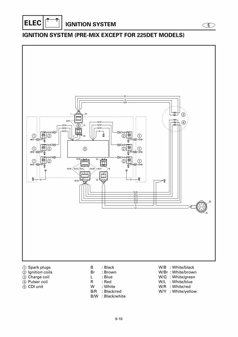
8-10
– +ELEC EIGNITION SYSTEM
IGNITION SYSTEM (PRE-MIX EXCEPT FOR 225DET MODELS) 8
8160
1
1
3
3
5
5
2
2
4
4
6
6
1 2
1 2
1 2
1
1
1
2
2
2
3
4
5
B/WB/WB/W
B/W
B/WB/W
B
B
W
B
W/LW/G
WB
RB/R
LBr
B
B
L Br
B/R
R
BrL
W/Br
W/YW/BW/R
W
W/Br W/YW/LW/GW/R
W/B
W/B W
8
1 Spark plugs2 Ignition coils3 Charge coil4 Pulser coil5 CDI unit
B : BlackBr : BrownL : BlueR : RedW : WhiteB/R : Black/redB/W : Black/white
W/B : White/blackW/Br : White/brownW/G : White/greenW/L : White/blueW/R : White/redW/Y : White/yellow

8-11
– +ELEC EIGNITION SYSTEM
INSPECTING THE IGNITION SPARK
GAP 8
WARNING
• Do not touch any of the connections of
the spark gap tester lead wires.
• Do not let sparks leak out of the removed
spark plug cap.
• Keep flammable gas or liquids away,
since this test can produce sparks.
Inspect:• Ignition spark gap
Above specification → Replace thespark plug.Below specification → Inspect the CDIunit output.
Inspecting steps
(1) Remove the spark plugs from theengine.
(2) Connect a spark plug cap to the sparkgap tester.
(3) Set the spark gap length on the adjust-ing knob.
(4) Crank the engine and observe thespark through the discharge windowof the spark gap tester.
Ignition spark gap9 mm (0.4 in)
Spark gap testerYM-34487 / 90890-06754
8200
8210
8220
8230
8240

8-12
– +ELEC EIGNITION SYSTEM
MEASURING THE IGNITION SYSTEM
PEAK VOLTAGE 8
WARNING
When checking the peak voltage do not
touch any of the connections of the digital
tester lead wires.
NOTE:
• If there is no spark or the spark is weak,continue with the ignition system test.
• If a good spark is obtained, the problem isnot with the ignition system, but possiblywith the spark plug(s) or another compo-nent.
1. Measure:• CDI unit output peak voltage
Above specification → Replace theignition coil.Below specification → Measure thecharge coil output peak voltage.
NOTE:
With the oil injection and 225DET models,the CDI unit output peak voltage for cylin-ders #2 and #5 is “0” at either cranking or1,500 r/min.
CDI unit output peak voltage (oil injection and 225DET models)
Black/white (B/W) – Black (B)
r/minCircuit Loaded
Cranking 1,500 3,500
V — 130 145 145
CDI unit output peak voltage (pre-mix except for 225DET models)
Black/white (B/W) – Black (B)
r/minCircuit Loaded
Cranking 1,500 3,500
V — 65 140 135
8250

8-13
– +ELEC EIGNITION SYSTEM
2. Measure:• Charge coil output peak voltage
Above specification → Measure thepulser coil output peak voltage. Below specification → Replace thecharge coil.
Charge coil output peak voltage (oil injection and 225DET models)
Red (R) – Brown (Br)
r/minCircuit Loaded
Cranking 1,500 3,500
V 140 160 165 165
Black/red (B/R) – Blue (L)
r/minCircuit Loaded
Cranking 1,500 3,500
V 40 55 165 165
Test harness (4-pin)YB-38831 / 90890-06771
Charge coil output peak voltage (pre-mix except for 225DET models)
Red (R) – Brown (Br)
r/minCircuit Loaded
Cranking 1,500 3,500
V 80 90 165 165
Black/red (B/R) – Blue (L)
r/minCircuit Loaded
Cranking 1,500 3,500
V 30 30 160 170
Test harness (4-pin)YB-38831 / 90890-06771
8260

8-14
– +ELEC EIGNITION SYSTEM
3. Measure:• Pulser coil output peak voltage
Above specification → Replace theCDI unit.Below specification → Replace thepulser coil.
Å Oil injection and 225DET modelsı Pre-mix except for 225DET models
Pulser coil output peak voltage (oil injection and 225DET models)
White/red (W/R) – White/green (W/G)White/yellow (W/Y) – White/brown (W/Br)
r/minCircuit Loaded
Cranking 1,500 3,500
V 3.0 2.0 8.0 14
Test harness (4-pin)YB-38831 / 90890-06771
Pulser coil output peak voltage (pre-mix except for 225DET models)
White/red (W/R) – White/green (W/G)White/black (W/B) – White/blue (W/L)White/yellow (W/Y) – White/brown (W/Br)
r/minCircuit Loaded
Cranking 1,500 3,500
V 2.5 2.0 9.5 16
Test harness (6-pin)YB-38832 / 90890-06772
8270
8275

8-15
– +ELEC EIGNITION SYSTEM
INSPECTING THE SPARK PLUG CAPS8
1. Inspect:• Spark plug cap
Loose connection → Tighten.Cracks/damage → Replace.
Replacement steps (oil injection and
225DET models)
(1) To remove the spark plug cap turn itcounterclockwise.
(2) To install the spark plug cap turn itclockwise until it is tight.
8280
Replacement steps (pre-mix except for
225DET models)
(1) Remove the spark plug cap off of thelead.
(2) Remove the spark plug cap spring.(3) Strip the insulation cover 5 mm (0.2
in) a and spread the core wires out-ward.
(4) Fit the spark plug cap spring close tothe spread core wires and bend theend of the spring around the lead.
(5) Install the spark plug cap spring intothe spark plug cap.
8285
8286
2. Measure: (oil injection and 225DET models)• Spark plug cap resistance
Out of specification → Replace.
Spark plug cap resistance4.0 - 6.0 kΩ
8290

8-16
– +ELEC EIGNITION CONTROL SYSTEM
IGNITION CONTROL SYSTEM (OIL INJECTION AND 225DET MODELS) 8
8300
L
B
L
B1
P
B
Gy/B
B2
P
BB2
Gy/B
3G
G
G G
L
B
Gy/B
B
L/RL/G
L/W
Gy/BLBB L/GL/R
L/W
L/W
B/Y4
5
6
B
Gy/B
Gy
A
1 Emergency switch2 Thermo switch3 Crank position sensor4 Engine cooling water
temperature sensor5 Oil level sensor
(except for 225DET)6 CDI unit
Å To the trim sensor B : BlackL : BlueP : PinkB/Y : Black/yellowGy/B : Gray/blackL/G : Blue/greenL/R : Blue/redL/W : Blue/white
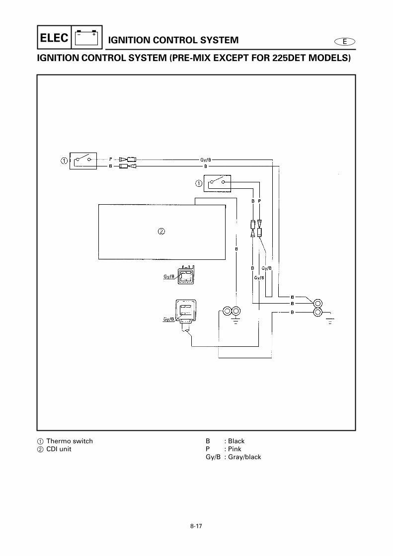
8-17
– +ELEC E
IGNITION CONTROL SYSTEM (PRE-MIX EXCEPT FOR 225DET MODELS)8
8305
1 Thermo switch2 CDI unit
B : BlackP : PinkGy/B : Gray/black
IGNITION CONTROL SYSTEM

8-18
– +ELEC EIGNITION CONTROL SYSTEM
MEASURING THE CRANK POSITION
SENSOR OUTPUT PEAK VOLTAGE 8
Measure:• Crank position sensor output peak
voltageBelow specification → Replace.
Crank position sensor output peak voltage
Green (G) – Green (G)
r/minCircuit Loaded
Cranking 1,500 3,500
V 3.0 2.0 5.5 6.0
8310
MEASURING THE ENGINE COOLING
WATER TEMPERATURE SENSOR
RESISTANCE 8
Measure:• Engine cooling water temperature
sensor resistanceOut of specification → Replace.
Engine cooling water temperature sensor resistance
Black/yellow (B/Y) –Black/yellow (B/Y)
5 ˚C (41 ˚F): 128 kΩ 20 ˚C (68 ˚F): 54 - 69 kΩ 100 ˚C (212 ˚F): 3.02 - 3.48 kΩ
Measuring steps
(1) Place the engine cooling water tem-perature sensor in a container filledwith water.
(2) Place a thermometer in the water.(3) Slowly heat the water.(4) Measure the resistance when the spec-
ified temperature is reached.
8320

8-19
– +ELEC EIGNITION CONTROL SYSTEM
INSPECTING THE THERMO SWITCH
CONTINUITY 8
Inspect:• Thermo switch continuity
Out of specification → Replace.
1 No continuity Å Temperature2 Continuity ı Time
Measuring steps
(1) Place the thermo switch in a containerfilled with water.
(2) Place a thermometer in the water.(3) Slowly heat the water.(4) Measure the continuity when the spec-
ified temperature is reached.
INSPECTING THE OIL LEVEL
SENSOR CONTINUITY 8
Inspect:• Oil level sensor continuity
Out of specification → Replace.
Thermo switch continuity temperature
Pink (P) – Black (B)a 84 - 90 ˚C (183 - 194 ˚F)b 60 - 74 ˚C (140 - 165 ˚F)
Float
position
Lead color
Black
(B)
Blue/
white
(L/W)
Blue/
green
(L/G)
Blue/
red
(L/R)
Å ON
Å OFF
ı ON
ı OFF
Ç ON
Ç OFF
Float distancea: 3 - 6 mm (0.12 - 0.24 in)b: 33 - 36 mm (1.30 - 1.42 in)c: 53 - 56 mm (2.09 - 2.20 in)
8330
8340
8690

8-20
– +ELEC E
INSPECTING THE EMERGENCY
SWITCH 8
1. Inspect:• Emergency switch continuity
Out of specification → Replace.
2. Inspect:• Emergency switch
Does not automatically return to thehome position → Replace.
Switch
position
Lead color
Blue (L) – Black (B)
Home a No continuity
On b Continuity
8710
IGNITION CONTROL SYSTEM

8-21
– +ELEC
E
STARTING SYSTEM
STARTING SYSTEM 8
8500
1
Fuse (20A)
2
Fuse (30A)
3
Fuel enrichment valve
4
Starter motor
5
Battery
6
Starter relay
Å
Oil injection and 225DET models
ı
Pre-mix except for 225DET models
B : BlackBr : BrownL : BlueR : Red

8-22
– +ELEC
E
INSPECTING THE BATTERY 8
Refer to “INSPECTING THE BAT-TERY” on page 3-20.
INSPECTING THE FUSES 8
1. Inspect:• Fuse holder continuity
No continuity
→
Check the fuse holderleads.
2. Inspect:• Fuse holder lead continuity
No continuity
→
Replace the fuseholder.Continuity
→
Inspect the fuse.3. Inspect:
• Fuse continuityNo continuity
→
Replace.• Fuse rating
Out of specification
→
Replace.
Fuse rating12 V - 20, 30 A
8510
INSPECTING THE WIRE HARNESS
CONTINUITY 8
Inspect:• Wire harness continuity
No continuity
→
Replace.
INSPECTING THE WIRE
CONNECTIONS 8
Inspect:• Wire connections
Poor connection
→
Properly connect.
STARTING SYSTEM

8-23
– +ELEC
E
INSPECTING THE STARTER RELAY 8
1. Inspect:• Brown lead terminal• Black lead terminal
Poor connection
→
Properly connect.2. Inspect:
• Starter relay continuity No continuity
→
Replace.
Inspecting steps
(1) Connect the tester and batterybetween the starter relay terminals.
(2) Inspect that there is continuitybetween the starter relay terminals.
Positive digital tester probe
1
→
Starter relay terminal
Negative digital tester probe
2
→
Starter relay terminal
Positive battery terminal
→
Brown lead
3
Negative battery terminal
→
Black lead
4
8520
8521
MEASURING THE FUEL ENRICHMENT
VALVE 8
Measure:• Fuel enrichment valve resistance
Out of specification
→
Replace.
Fuel enrichment valve resistanceBlue (L) – Black (B)
3.4 ~ 4.0
Ω
at 20 ˚C (68 ˚F)8525
STARTING SYSTEM

8-24
– +ELEC
E
STARTER MOTOR
STARTER MOTOR 8
DISASSEMBLING/ASSEMBLING THE STARTER MOTOR 8
Order Job/Part Q’ty RemarksStarter motor Refer to “RELAY ASSEMBLY AND
STARTER MOTOR” on page 5-16.1 Bolt 22 Starter motor bracket 13 Clip 14 Starter motor pinion stopper 15 Spring 16 Starter motor pinion 1
Continued on next page.
8530

8-25
– +ELEC
E
STARTER MOTOR
8
8
Order Job/Part Q’ty Remarks7 Bolt 28 Upper cover 19 O-ring 110 Washer 211 Lower bracket 112 O-ring 113 Stator 114 Armature 1
Continued on next page.
8530

8-26
– +ELEC
E
STARTER MOTOR
8
8
Order Job/Part Q’ty Remarks15 Metal plate 116 Nut 117 O-ring 118 Screw 219 Brush assembly 120 Spring 321 Brush holder 1
For assembly, reverse the disassembly procedure.
8530

8-27
– +ELEC
E
STARTER MOTOR
REMOVING THE STARTER MOTOR
PINION 8
Remove:• Clips
1
NOTE:
Slide the pinion stopper
1
down as shown
and then remove the clip
2
.8540
INSPECTING THE STARTER MOTOR
PINION 8
1. Inspect:• Starter motor pinion teeth
Damage/wear
→
Replace.2. Inspect:
• Starter motor pinion movementIncorrect
→
Replace.
NOTE:
Rotate the starter motor pinion clockwiseand make sure it moves smoothly. Also,rotate the starter motor pinion counter-
clockwise and make sure it locks.
8550
INSPECTING THE ARMATURE 8
1. Inspect:• Commutator
Foreign matter
→
Clean.(with 600 grit sandpaper)
8560
2. Measure:• Commutator diameter
Out of specification
→
Replace.
Commutator diameter limit31.0 mm (1.22 in)
8570

8-28
– +ELEC
E
STARTER MOTOR
3. Inspect:• Commutator undercut
Dirt/foreign matter
→
Clean.(with compressed air)
8580
4. Measure:• Commutator undercut
a Out of specification → Replace thearmature.
Commutator undercut limit0.2 mm (0.01 in)
8590
5. Inspect:• Armature continuity
Out of specification → Replace.
Armature continuity
Commutator
segments a Continuity
Segment –
Armature core b No continuity
Segment –
Armature shaft c No continuity
8600
MEASURING THE BRUSHES 8
1. Measure:• Brush length a
Out of specification → Replace thebrush assembly.
Brush length limit12.0 mm (0.47 in)
8610

8-29
– +ELEC ESTARTER MOTOR
2. Inspect:• Brush assembly continuity
Out of specification → Replace thebrush assembly.
Brush assembly continuity
Brush 1 – Brush 2 Continuity
Brush 1 – Brush 3
Brush 2 – Brush 3
Brush holder 4 –
Brush assembly holder 5
No continuity
8620

8-30
– +ELEC ECHARGING SYSTEM
CHARGING SYSTEM 8
8630
G/W
G
B
R
R
R
B B
G G G
G
G
G
B
R
R
R
R
R
R
B
B B
2
1
4
33
1
2
4
5
4
B
1 Rectifier/regulator2 Lighting coil3 Battery4 Fuses (20A, 30A)5 Battery lead terminal
Å Oil injection and 225DET modelsı Pre-mix except for 225DET models
B : BlackG : GreenR : RedG/W : Green/white

8-31
– +ELEC E
INSPECTING THE RECTIFIER/
REGULATOR 8
1. Inspect:(oil injection and 225DET models)• Rectifier/regulator continuity
Out of specification → Replace.
: Continuity: No continuity
NOTE:
There are three green and one red terminal.The resistance between black and each ofthese terminals is the same.
2. Inspect:(pre-mix except for 225DET models)• Rectifier/regulator continuity
: Continuity: No continuity
Rectifier/regulator continuity
1 Black (B)
2 Green (G)
3 Red (R)
1 Black (B)
2 Green (G) ∞
3 Red (R) ∞ ∞
Rectifier/regulator continuity
1 Green (G1)
2 Green (G2)
3 Red (R)
4 Black
(B)
1 Green (G1)
2 Green (G2)
∞ ∞
3 Red (R)
∞ ∞ ∞
4 Black
(B)
8640
∞
8650
∞
CHARGING SYSTEM

8-32
– +ELEC E
MEASURING THE LIGHTING COIL
OUTPUT PEAK VOLTAGE 8
Measure:• Lighting coil output peak voltage
Above specification → Replace therectifier/regulator.Below specification → Replace thelighting coil.
Å Oil injection and 225DET modelsı Pre-mix except for 225DET models
Lighting coil output peak voltage (oil injection and 225DET models)
Green (G) – Green (G)
r/minCircuit Loaded
Cranking 1,500 3,500
V — — 35 85
Test harness (3-pin)YB-06770 / 90890-06770
Lighting coil output peak voltage (pre-mix except for 225DET models)
Green/white (G/W) – Green (G)
r/minCircuit Loaded
Cranking 1,500 3,500
V — — 20 50
8660
Å
8670
ı
INSPECTING THE FUSES 8
Refer to “INSPECTING THE FUSES”on page 8-22.
INSPECTING THE BATTERY 8
Refer to “INSPECTING THE BAT-TERY” on page 3-20.
CHARGING SYSTEM

8-33
– +ELEC E
POWER TRIM AND TILT SYSTEM 8
8700
45Ç
1
2
M
G
B
L
2 B
B B
B
B
B B
6
+ -
LgSb
LgSb
Lg Sb
ı 4
RR RR
7
O
P
B
Gy
P
B O
R Sb Lg
Sb
RLg Lg
Å
RSb Lg
DOWN
FREE
UP
3
Sb SbLg
R
Î
1 Power trim and tilt motor2 Power trim and tilt relay3 Trailer switch4 Fuse (20A)5 Fuse (30A)6 Battery7 Trim sensor
Å To remote controlı Pre-mix except for 225DET
modelsÇ Oil injection and 225DET
modelsÎ To trim meter
B : BlackG : GreenGy : GrayL : BlueLg : Light greenO : OrangeP : PinkR : RedSb : Sky blueGy/B: Gray/black
POWER TRIM AND TILT SYSTEM

8-34
– +ELEC E
INSPECTING THE FUSES 8
Refer to “INSPECTING THE FUSES”on page 8-22.
INSPECTING THE BATTERY 8
Refer to “INSPECTING THE BAT-TERY” on page 3-20.
INSPECTING THE POWER TRIM
AND TILT RELAY 8
1. Inspect:• Power trim and tilt relay assembly
continuityOut of specification → Inspect thepower trim and tilt relay continuity.
2. Inspect:• Power trim and tilt relay continuity
Out of specification → Replace.
Power trim and tilt relay assembly continuity
Sky blue (Sb) – Black (B)
Light green (Lg) – Black (B)Continuity
Power trim and tilt relay continuity
Sky blue (Sb) lead –
Black (B) lead
Light green (Lg) lead –
Black (B) lead
Continuity
Sky blue (Sb) lead –
Terminal 1
Light green (Lg) lead –
Terminal 1
Continuity
Sky blue (Sb) lead –
Terminal 2
Light green (Lg) lead –
Terminal 2
No continuity
Terminal 1 – Terminal 3 Continuity
Terminal 2 – Terminal 3 No continuity
8760
8770
POWER TRIM AND TILT SYSTEM

8-35
– +ELEC E
3. Inspect:• Power trim and tilt relay operation
No continuity → Replace.
Inspecting steps
(1) Connect the tester between the powertrim and tilt relay terminals.
(2) Connect a 12-V battery as shown.
(3) Check that there is continuity betweenthe power trim and tilt relay terminals.
Sky blue (Sb) lead → Positive terminal
Black (B) lead → Negative terminal
Light green (Lg) lead → Positive terminal
Black (B) lead → Negative terminal
8775
INSPECTING THE TRAILER SWITCH
CONTINUITY 8
Inspect:• Trailer switch continuity
Out of specification → Replace.
Switch
position
Lead color
Sky blue
(Sb)Red (R)
Light
green
(Lg)
Up
Free
Down
8780
POWER TRIM AND TILT SYSTEM

8-36
– +ELEC EPOWER TRIM AND TILT SYSTEM
MEASURING THE TRIM SENSOR
RESISTANCE 8
Measure:• Trim sensor resistance
Out of specification → Replace.
NOTE:
Turn the lever 1 and measure the resis-tance as it gradually changes.
Trim sensor resistancePink (P) – Black (B)
582 - 873 Ω at 20 ˚C (68 ˚F)Orange (O) – Black (B)
800 - 1,200 Ω at 20 ˚C (68 ˚F)
8790

8-37
– +ELEC E
POWER TRIM AND TILT MOTOR 8DISASSEMBLING/ASSEMBLING THE POWER TRIM AND TILT MOTOR 8
Order Job/Part Q’ty RemarksPower trim and tilt motor Refer to “RESERVOIR AND POWER TRIM
AND TILT MOTOR” on page 7-24.1 Screw 12 Lead holder 13 Screw 24 Stator 15 Armature 16 O-ring 17 Screw 2
Continued on next page.
8800
POWER TRIM AND TILT MOTOR

8-38
– +ELEC E
88
Order Job/Part Q’ty Remarks8 Brush holder 29 Brush 210 Spring 211 Lower cover 112 Oil seal 113 Bearing 1
For assembly, reverse the disassembly procedure.
8800
POWER TRIM AND TILT MOTOR

8-39
– +ELEC E
REMOVING THE STATOR 8
Remove:• Stator 1
CAUTION:
• Keep the power trim and tilt motor leads
inside the stator.
• Do not allow grease or oil to contact the
commutator.
NOTE:
• Remove the lead holder 2 and rubberspacer 3 from the stator and slide themtowards the leads.
• Hold the end of the armature shaft with aclean cloth and pull off the stator.
8810
REMOVING THE BRUSH 8
1. Remove:• Sky blue power trim and tilt motor
lead 1
NOTE:
Hold the brush with a screwdriver asshown. Then, disconnect the sky blue lead.
8820
2. Remove:• Brush holders 1 • Brushes 2
CAUTION:
Do not touch the bimetal a; touching it
may affect the operation of the breaker.
8830
INSPECTING THE BRUSH 8
1. Measure:• Brush length a
Out of specification → Replace.
Brush length4.8 mm (0.19 in)
8840
POWER TRIM AND TILT MOTOR

8-40
– +ELEC EPOWER TRIM AND TILT MOTOR
2. Inspect:• Brush continuity
No continuity → Replace.
CAUTION:
Do not touch the bimetal a; touching it
may affect the operation of the breaker.
8850
INSPECTING THE ARMATURE 8
1. Measure:• Commutator diameter a
Out of specification → Replace.
Commutator diameter limit21.0 mm (0.83 in)
8860
2. Measure:• Commutator undercut a
Out of specification → Replace thearmature.
Commutator undercut limit0.85 mm (0.03 in)
8870
3. Inspect:• Armature continuity
Out of specification → Replace.
Armature continuity
Commutator segments Continuity
Segment-laminations No continuity
Segment-shaft No continuity8880
8890

8-41
– +ELEC EPOWER TRIM AND TILT MOTOR
INSTALLING THE BRUSH 8
Install:• Brushes 1 • Brush holders 2 • Power trim and tilt motor leads 3 • Screw 4
CAUTION:
Do not touch the bimetal; touching it may
affect the operation of the breaker.
8900
INSTALLING THE ARMATURE 8
Install:• Armature 1
NOTE:
Push the brushes into the holder and theninstall the armature.
8910
INSTALLING THE STATOR 8
Install:• Stator 1
NOTE:
Place a clean cloth over the end of thearmature shaft and carefully push the arma-ture into the stator with a pair of pliers asshown.8920

E
1 2 3 4 5 6 7 8 9
TRBLANLS
CHAPTER 9
TROUBLE ANALYSIS
TROUBLE ANALYSIS
..................................................................................... 9-1TROUBLE ANALYSIS CHART ................................................................. 9-1
SELF-DIAGNOSIS
........................................................................................... 9-4DIAGNOSIS CODE INDICATION............................................................. 9-4DIAGNOSIS THE ELECTRONIC CONTROL SYSTEM ............................ 9-4

9-1
ETRBLANLS
TROUBLE ANALYSIS
TROUBLE ANALYSIS 9
NOTE:
The following items should be checked before the “TROUBLE ANALYSIS CHART” is con-sulted.1. The battery is charged and its specified gravity is within specification.2. There are no incorrect wiring connections.3. Wiring connections are properly secured and are not rusty.4. The lanyard is installed onto the engine stop switch.5. The shift position is in neutral.6. Fuel is reaching the carburetor.7. The rigging and engine setting are correct.
8. The engine is free from any “Hull problem”.
TROUBLE ANALYSIS CHART 9
Trouble mode Check elements
EN
GIN
E W
ILL
NO
T S
TA
RT
HA
RD
ST
AR
TIN
G
RO
UG
H ID
LIN
G
HIG
H ID
LIN
G
EN
GIN
E S
TA
LLS
PO
OR
AC
CE
LER
AT
ION
EN
GIN
E W
ILL
NO
T S
TO
P
PO
OR
PE
RFO
RM
AN
CE
LIM
ITE
D E
NG
INE
SP
EE
D
OV
ER
HE
AT
ING
LOO
SE
ST
EE
RIN
G
LOO
SE
TIL
T H
OLD
ING
TIL
T M
OT
OR
WIL
L N
OT
RU
N
HA
RD
SH
IFT
ING
IRR
EGU
LAR
WA
RN
ING
IND
ICA
TIO
N
PO
OR
BA
TT
ER
Y C
HA
RG
ING
Relative part Reference chapter
FUEL SYSTEM
Fuel line 3Fuel filter 3Fuel joint 4Fuel pumps 4Carburetors 4• Idle speed 3• Link adjustment 3• Pilot screw setting 4
POWER UNIT
Compression 3Reed valves 5Cylinder head gaskets 5Seal 5Cylinder block 5Crankcase 5Piston rings 5Pistons 5Bearings 5

9-2
ETRBLANLS
TROUBLE ANALYSIS
Thermostat 5Water passages 5
LOWER UNIT
Neutral position 6Dog clutch 6Gears 6Water inlets 6Water pump 6Propeller shaft(s) 6Shift rod joint/pin 6Shift cam 6Shift shaft 6Lower case 6
BRACKET UNIT
Bracket 7Rubber mount 7Shift rod 7
POWER TRIM AND TILT UNIT
Fluid level 3Relief valve 7Fluid passages —Power trim and tilt motor 7
ELECTRICAL
Ignition system
• Charge coil 8• Pulser coils 8• CDI unit 8• Ignition coils 8• Spark plugs 3
Ignition control system
• Lanyard switch —• Crank position sensor 8• Engine cooling water
temperature sensor 8
Trouble mode Check elements
EN
GIN
E W
ILL
NO
T S
TA
RT
HA
RD
ST
AR
TIN
G
RO
UG
H ID
LIN
G
HIG
H ID
LIN
G
EN
GIN
E S
TA
LLS
PO
OR
AC
CE
LER
AT
ION
EN
GIN
E W
ILL
NO
T S
TO
P
PO
OR
PE
RFO
RM
AN
CE
LIM
ITE
D E
NG
INE
SP
EE
D
OV
ER
HE
AT
ING
LOO
SE
ST
EE
RIN
G
LOO
SE
TIL
T H
OLD
ING
TIL
T M
OT
OR
WIL
L N
OT
RU
N
HA
RD
SH
IFT
ING
IRR
EGU
LAR
WA
RN
ING
IND
ICA
TIO
N
PO
OR
BA
TT
ER
Y C
HA
RG
ING
Relative part Reference chapter
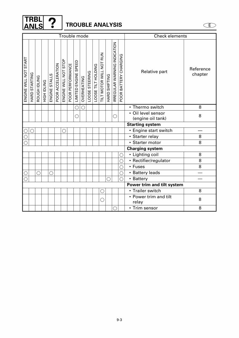
9-3
ETRBLANLS
TROUBLE ANALYSIS
• Thermo switch 8• Oil level sensor
(engine oil tank) 8
Starting system
• Engine start switch —• Starter relay 8• Starter motor 8
Charging system
• Lighting coil 8• Rectifier/regulator 8• Fuses 8• Battery leads —• Battery —
Power trim and tilt system
• Trailer switch 8• Power trim and tilt
relay 8
• Trim sensor 8
Trouble mode Check elements
EN
GIN
E W
ILL
NO
T S
TA
RT
HA
RD
ST
AR
TIN
G
RO
UG
H ID
LIN
G
HIG
H ID
LIN
G
EN
GIN
E S
TA
LLS
PO
OR
AC
CE
LER
AT
ION
EN
GIN
E W
ILL
NO
T S
TO
P
PO
OR
PE
RFO
RM
AN
CE
LIM
ITE
D E
NG
INE
SP
EE
D
OV
ER
HE
AT
ING
LOO
SE
ST
EE
RIN
G
LOO
SE
TIL
T H
OLD
ING
TIL
T M
OT
OR
WIL
L N
OT
RU
N
HA
RD
SH
IFT
ING
IRR
EGU
LAR
WA
RN
ING
IND
ICA
TIO
N
PO
OR
BA
TT
ER
Y C
HA
RG
ING
Relative part Reference chapter

9-4
ETRBLANLS
SELF-DIAGNOSIS
SELF-DIAGNOSIS 9
DIAGNOSIS CODE INDICATION 9
1. Normal condition(no defective part or irregular process-ing is found)
2. Single flash is given every 5 seconds.
a
: Light on, 0.3 second
b
: Light off, 5 seconds9010
3. Trouble code indicationExample: The illustration indicates codenumber 23.
a
: Light on, 0.3 second
b
: Light off, 0.3 second
c
: Light off, 1.7 seconds
d
: Light off, 5 seconds
9020
DIAGNOSIS THE ELECTRONIC
CONTROL SYSTEM 9
1. Install:• Diagnostic indicator
NOTE:
When performing this diagnosis, all of theelectrical wires must be properly con-
nected.
Diagnostic indicatorYB-06765 / 90890-06765
9030
2. Inspect:• Diagnosis code
Code 1 is indicated
→
Normal.Code 12 - 21 indicated
→
Check theapplicable parts.Code 33 - 44 indicated
→
Replace theCDI unit.

9-5
ETRBLANLS
SELF-DIAGNOSIS
Inspecting steps
(1) Start the engine and let it idle.(2) Check the diagnostic indicator’s flash
pattern to determine if there are anymalfunctions.
NOTE:
When mor e than one problem is detected,the diagnostic tester’s light flashes in thepattern of the lowest numbered problem.After that problem is corrected, the lightflashes in the pattern of the next lowestnumbered problem. This continues until all
of the problems are detected and corrected.
Diagnosis code chart 8
Code Symptoms
12 Incorrect charge coil input sig-nal
13 Incorrect pulser coil input sig-nal
14 No crank position sensor input signal
15Incorrect engine cooling water temperature sensor input sig-nal
33 ~ 44 Microcomputer processing information
(33)Ignition timing is being slightly corrected (when starting a cold engine)
(41) Overrevolution control (during ignition cutoff operation)
(42) Overheat control/oil empty con-trol
(43) Buzzer sounding
(44) Engine stop switch control operating
9040

B
Sb Sb
W/RW/YW/L
W/Br
BL L
WIRING DIAGRAM
2
4
6
3
1
5
BrB/W
B/W
B/W
B/W B/W
B/W B/W
B/W B/W
B
P
P
B
B
B
B/W
B/W
B
B
B/W
P
B
B
Gy
150AET, L150AET, 175AET, 200AET, L200AET/C150TR
Fuse (20A)
Power trim and tilt motor
CDI unit
Thermoswitch
1
Starter motor2
Battery4
Power trim and tilt relay
9
Power trim and tilt relay
9
Starterrelay
3
=
5
6
7
7
7
Spark plug
Spark plug
Spark plug
Thermoswitch
6
7
7
7
Spark plug
Spark plug
Spark plug
8 Ignition coil
8
8
Ignition coil
8 Ignition coil
Ignition coil
8
8
Ignition coil
Ignition coil
G/W
W/G
W/Y
W/BrW/L
W/R W/B
C Pulser coil
B Lighting coil
D Rectifier/ regulator
ACharge coil
Br
B
B
R
B
BBBBB
P P
PRG
Sb
W
L
BBr
Y
Lg
Å To remote control
EFuel enrichment valve
Br
B/RR L
W/G W/B
B
RR
G
G
OB
GyP
Gy
O P B
O P B
ı To trim meter
F Trim sensor
M
N
S
M
N
S
R
R
R
B
B
Lg
Lg
R
L G
R
B
B
Br
G
Gy
L
Lg
O
P
R
Sb
W
Y
B/R
B/W
G/W
W/B
W/Br
W/G
W/L
W/R
W/Y
Black
Brown
Green
Gray
Blue
Light green
Orange
Pink
Red
Sky blue
White
Yellow
Black/red
Black/white
Green/white
White/black
White/brown
White/green
White/blue
White/red
White/yellow
COLOR CODE
:
:
:
:
:
:
:
:
:
:
:
:
:
:
:
:
:
:
:
:
:
B
BB
B
B R R
P P
P B
L LBr
B/R B/RR
B
W P
PGBPWRBrSbLg
PB
R

B L
L
Gy/B
Gy/B
G
G
G
G
B
Sb Sb
Sb
Sb
W/RW/Y W/Br
BL L
WIRING DIAGRAM
2
4
6
3
1
5
BrB/W
B/W
B/W
B/W B/W
B/W B/W
B/W B/W
B
P
Gy/B
B
B
B
B/W
B/W
B
B
B/W
P
B B
Gy
150FETO, S150FETO, L150FETO, LS150FETO, 150GETO, D150HETO, 175DETO, S175DETO,
175FETO, 200FETO, S200FETO, L200FETO, LS200FETO, 200GETO, 225DET, 225DETO/
150TR, S150TR, L150TR, P150TR, D150TR, S175TR, P175TR, 200TR, S200TR, L200TR, P200TR
Fuse (30A)
Power trim and tilt motor
CDI unit
Thermoswitch
1
Fuse (20A)
2
Starter motor3
Power trim and tilt relay
D
Power trim and tilt relay
D
Terminal5
Starterrelay
4
E
8
9
=
=
=
Spark plug
Spark plug
Spark plug
Thermoswitch
9
=
=
=
Spark plug
Spark plug
Spark plug
A Ignition coil
A
A
Ignition coil
A Ignition coil
Ignition coil
A
A
Ignition coil
Ignition coil
I Pulser coil
J Lighting coil
HCharge coil
GCrankpositionsensor
Br
BB
LFuel enrichment valve
Br
B/RR L
W/G
R
R
R
R
M
N
S
M
N
S
R R
R
R
Battery6
R R
B
B
B
Lg
Lg
Lg
R
RSb
Br
LgLgR
R
R
R
B
Br
G
Gy
L
Lg
O
P
R
Sb
W
Y
B/R
B/W
B/Y
G/B
G/R
Gy/B
L/G
L/R
L/W
W/Br
W/G
W/R
W/Y
Black
Brown
Green
Gray
Blue
Light green
Orange
Pink
Red
Sky blue
White
Yellow
Black/red
Black/white
Black/yellow
Green/black
Green/red
Gray/black
Blue/green
Blue/red
Blue/white
White/brown
White/green
White/red
White/yellow
COLOR CODE
:
:
:
:
:
:
:
:
:
:
:
:
:
:
:
:
:
:
:
:
:
:
:
:
:
B
Battery6
R
B
B
B
Å To accessories
L/WL/GL/R
B
Oil level sensor
Trailer switchF
C
BEngine coolingwatertemperaturesensor
B/Y
B/Y
B/Y
B
L L
B
Emergency switch
7
Gy/B
Gy/B
L/W L/G
BL/R W/Br W/G
W/Y W/R
G G G
KRectifier/regulator
R
B
Fuse (30A)1
B
LG/B G/R
Br
B/R L
BBrB
B/R L
Br Br
B/R
B/R
B
L
Y Y
B L G/R G/B
G/B
L M
N
S @
NOil pump(sub-oil tank)
OOil level switch(sub-oil tank)
Ç To oil levelmeter
M Trim sensor
Br
Br
Br Br
G
G GG
PRG
Sb
W
L
BBr
Y
Lg
To remotecontrol
L G
B
B
B
B
Lg
R R
Sb Lg
Sb
LgR
L LBr
B/R B/RR
Î
B
B
B
B L
B
B B
LW Gy/BB
G/BG
PBr
G/RY
O P B
Gy/B
Gy
ı To trim meter
OB
GyP
LY
GW
PB
Br
BrBrSbRLg
R
Gy/BG/B
G/R
Gy/BL
BB
BR
LGy/B
B
Gy/B Gy/BG/BG/R
R
B BBPWGY YL
L BrB
LBGy/B
BrSbRLg
SbR
Lg


Printed on recycled paper
YAMAHA MOTOR CO., LTD.
Printed in USAOct. 1998 – ?.? × 1 CR(150AET, L150AET, 150FETO, L150FETO, 150GETO, D150HETO, 175AET, 175DETO, 175FETO,200AET, L200AET, 200FETO, L200FETO, 200GETO, 225DET, 225DETO)