1.5a - trudeau
TRANSCRIPT
ViaSat Proprietary
Mr. Tim Trudeau ViaSat, Inc.
9-11 November 2010
Introduction to LINK 16/MIDS LVT MilCIS 2010
ViaSat Brings Your Network To Life
Topics of Discussion
Link 16 MIDS Low Volume Terminal (LVT) Small Tactical Terminal (STT)

ViaSat Brings Your Network To Life
Acronyms
Acronym Definition Acronym Definition Acronym DefinitionACA Alternating Current Adapter FOM Functional Output Message PA Power AdapterADDSI Army Data Distribution System Interface HPA High Power Amplifier PPLI Precise Participant Location & IdentificationAIU Antenna Interface Unit HIA High-Power Interface Adapter PR Position ReferenceAV MUX Avionics Multiplexer HUR High Update Rate PTN Primary Track NumberAP Adaptable Parameter IBIT Manually Initiated BIT RELNAV Relative NavigationARINC Aeronautical Radio, Inc. IE Information Exchange RNLAF Royal Netherlands Air ForceBCP Boot Computer Program ICD Interface Control Drawing RPS Remote Power SupplyBIM Bus Input Message IPS Internal Power Supply RTT-I Round Trip Timing (interrogate)BIT Built In Test JNDA Joint Network Design Aid RTT-R Round Trip Timing (reply)BOM Bus Output Message JTRS Joint Tactical Radio System Rx ReceiveCCA Circuit Card Assembly KBPS Kilo Bytes Per Second SBIT Start-up Built In TestCCI Cryptographic Controlled Item LEGS Link Environment Gateway Simulator SMP Signal/Message ProcessorCCPD Current Crypto Period Designator LIFE Link 16 Initialization File Editor SNC Secondary Navigation ControllerCDH CTIC DS101 HYBRID - COMSEC TRANSEC Integrated Circuit LinkS/S Link Simulator/Stimulator SRU Shop Replaceable UnitCIK Cryptographic Ignition Key LIFT Link 16 Flightline Tool SSS System Segment SpecificationCOMSEC Communications Security LMS Link Monitor System STDP Standard Double PulseCNI Communication Navigation Identification LPC Linear Predictive Coding TACAN Tactical Air NavigationCPSM Continuous Phase Shift Modulation LRU Line Replaceable Unit TCV Transmission Crypto Variable CSCI Computer Software Configuration Item LTTI Long Term Transmit Inhibit TDMA Time Division Multiple AccessCSS Computer Support System LVT Low Volume Terminal TDL-16 Tactical Data Link 16CT3 Common Tier 3 MIB Master Interconnect Board TIM Terminal Input MessageCTT Capable To Transmit MIDS Multifunctional Information Distribution Systems TIO Tailored Input/OutputCV Cryptographic Variable MOS MIDS On Ship TOA Time Of ArrivalCVLL Cryptographic Variable Logic Label MSEC Message Security TOD Time of DayCVSD Continuous Variable Slope Delta MSG Message TOM Terminal Output MessageDCA Direct Current Adapter MT Main Terminal TP/G Tailored Processor / Ground MultiplexerDDP Digital Data Processor NC Navigation Controller TR Time RefinementDLA Data Link Address (Link 4A) NDL Network Design Load TSA Time Slot AssignmentDTD Data Transfer Device NMDC Network Management Design Center (RNLAF) TSDF Time Slot Duty FactorDME Distance Measurement NPG Network Participation Group TSEC Transmission SecurityDP/A Data Processor/Aviation Multiplexer NTR Network Time Reference TSR Time Slot ReallocationDS Data Silent NVRAM Non-Volatile Random Access Memory Tx TransmitEDAC Error Detection and Correction OBIT Operational Built In Test UAS User Application ServiceETI Elapsed Time Indicator OCP Operation Computer Program UHF Ultra High Frequency EW Electronic Warfare OFP Operational Flight Program VAST ViaSat Analysis Support ToolFDL Fighter Data Link P2DP Pack Two Double Pulse VME Versa Module EurocardFIM Functional Input Message P2SP Pack Two Single Pulse VP Voice ProcessorFOM Functional Output Message P4SP Pack Four Single PulseIEJU Initial Entry JTIDS Unit RRN Recurrence Rate NumberIPF Internal Protection Feature RS (1&2) Receiver SynthesizerIPS Internal Power Supply RTI Receive/Transmit Interface

ViaSat Brings Your Network To Life
What is Link 16?
Link 16 is a tactical data link used to exchange real time tactical information between units of a force. Link 16 is identical in purpose to Link 11
and Link 4A with improvements in data exchange, link establishment, and security
Link 16 is often referred to as TDL J Uses J-Series messages
ViaSat Brings Your Network To Life
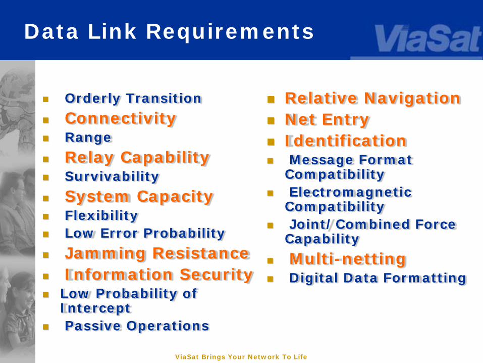
Data Link Requirements
Orderly Transition
Connectivity Range
Relay Capability Survivability
System Capacity Flexibility Low Error Probability
Jamming Resistance Information Security Low Probability of
Intercept Passive Operations
Relative Navigation Net Entry Identification Message Format
Compatibility Electromagnetic
Compatibility Joint/Combined Force
Capability
Multi-netting Digital Data Formatting
ViaSat Brings Your Network To Life
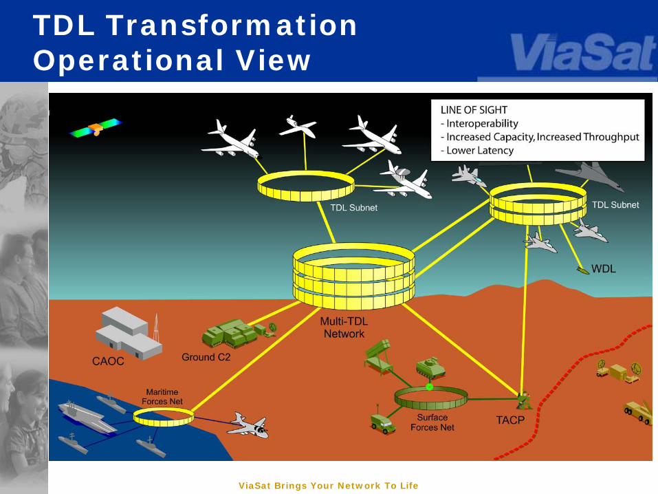
TDL TransformationOperational View
ViaSat Brings Your Network To Life
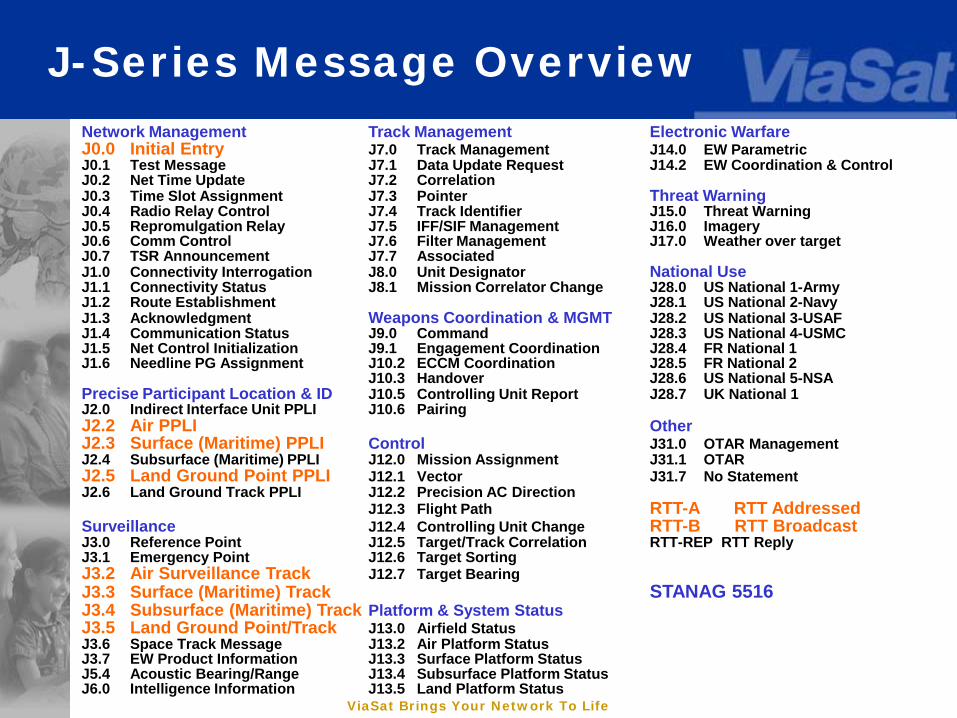
J-Series Message OverviewNetwork Management Track Management Electronic WarfareJ0.0 Initial Entry J7.0 Track Management J14.0 EW ParametricJ0.1 Test Message J7.1 Data Update Request J14.2 EW Coordination & ControlJ0.2 Net Time Update J7.2 CorrelationJ0.3 Time Slot Assignment J7.3 Pointer Threat WarningJ0.4 Radio Relay Control J7.4 Track Identifier J15.0 Threat WarningJ0.5 Repromulgation Relay J7.5 IFF/SIF Management J16.0 ImageryJ0.6 Comm Control J7.6 Filter Management J17.0 Weather over targetJ0.7 TSR Announcement J7.7 AssociatedJ1.0 Connectivity Interrogation J8.0 Unit Designator National UseJ1.1 Connectivity Status J8.1 Mission Correlator Change J28.0 US National 1-ArmyJ1.2 Route Establishment J28.1 US National 2-NavyJ1.3 Acknowledgment Weapons Coordination & MGMT J28.2 US National 3-USAFJ1.4 Communication Status J9.0 Command J28.3 US National 4-USMCJ1.5 Net Control Initialization J9.1 Engagement Coordination J28.4 FR National 1J1.6 Needline PG Assignment J10.2 ECCM Coordination J28.5 FR National 2
J10.3 Handover J28.6 US National 5-NSAPrecise Participant Location & ID J10.5 Controlling Unit Report J28.7 UK National 1J2.0 Indirect Interface Unit PPLI J10.6 PairingJ2.2 Air PPLI OtherJ2.3 Surface (Maritime) PPLI Control J31.0 OTAR ManagementJ2.4 Subsurface (Maritime) PPLI J12.0 Mission Assignment J31.1 OTARJ2.5 Land Ground Point PPLI J12.1 Vector J31.7 No StatementJ2.6 Land Ground Track PPLI J12.2 Precision AC Direction
J12.3 Flight Path RTT-A RTT AddressedSurveillance J12.4 Controlling Unit Change RTT-B RTT BroadcastJ3.0 Reference Point J12.5 Target/Track Correlation RTT-REP RTT ReplyJ3.1 Emergency Point J12.6 Target SortingJ3.2 Air Surveillance Track J12.7 Target BearingJ3.3 Surface (Maritime) Track STANAG 5516J3.4 Subsurface (Maritime) Track Platform & System StatusJ3.5 Land Ground Point/Track J13.0 Airfield StatusJ3.6 Space Track Message J13.2 Air Platform StatusJ3.7 EW Product Information J13.3 Surface Platform StatusJ5.4 Acoustic Bearing/Range J13.4 Subsurface Platform StatusJ6.0 Intelligence Information J13.5 Land Platform Status

ViaSat Brings Your Network To Life
Introduction
Link-16 does not significantly change the basic concepts of the tactical data link information exchange.
Provides technical and operational improvements to existing data link capabilities.
Link-16 uses Joint Tactical Information Distribution System (JTIDS) and the Multi-Functional Information Distribution System (MIDS) terminals (which are the communication component of Link-16)
ViaSat Brings Your Network To Life
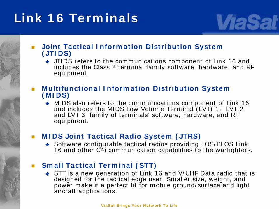
Link 16 Terminals
Joint Tactical Information Distribution System (JTIDS) JTIDS refers to the communications component of Link 16 and
includes the Class 2 terminal family software, hardware, and RF equipment.
Multifunctional Information Distribution System (MIDS) MIDS also refers to the communications component of Link 16
and includes the MIDS Low Volume Terminal (LVT) 1, LVT 2 and LVT 3 family of terminals’ software, hardware, and RF equipment.
MIDS Joint Tactical Radio System (JTRS) Software configurable tactical radios providing LOS/BLOS Link
16 and other C4i communication capabilities to the warfighters.
Small Tactical Terminal (STT) STT is a new generation of Link 16 and V/UHF Data radio that is
designed for the tactical edge user. Smaller size, weight, and power make it a perfect fit for mobile ground/surface and light aircraft applications.

ViaSat Brings Your Network To Life
Link 16 Features
Link 16 includes many features that improve data exchange normally seen on Link 11 Jam resistance Improved security Increased data rate Increased amounts and granularity of information
exchange Digitized, jam-resistant, secure voice capability Relative Navigation Precise Participant Location and Identification
(PPLI) improvement

ViaSat Brings Your Network To Life
Link 16 Architecture
Architectural Characteristics TDMA Format Nodeless Architecture Message and Transmission Security Spread Spectrum, Frequency Hopping
Waveform in the UHF Lx Band
ViaSat Brings Your Network To Life
Link 16 Features
Link 16 uses Time Division Multiple Access (TDMA) Automatic function of the Link 16
terminals that uses time interlacing to provide multiple communications nets.
Each JU uses pre-assigned sets of time slots to transmit their data and receive data from other units.
TDMA uses Epochs, Frames, and Time slots as a means of dividing time.
ViaSat Brings Your Network To Life
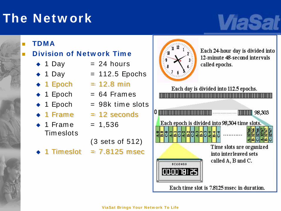
The Network
TDMA Division of Network Time
1 Day = 24 hours 1 Day = 112.5 Epochs 1 Epoch = 12.8 min 1 Epoch = 64 Frames 1 Epoch = 98k time slots 1 Frame = 12 seconds 1 Frame = 1,536
Timeslots (3 sets of 512)
1 Timeslot = 7.8125 msec

ViaSat Brings Your Network To Life
Link 16 Features
Nodeless A Node is a unit needed to establish and maintain
connectivity. Link 11 Net Control Station (NCS) is a Node for the link operations. If the NCS or Node goes down, the link goes down as well. Link 16 does not require a Node to establish and maintain connectivity. Link 16 uses Timeslots as part of the TDMA protocol to exchange information regardless on who enters and exits the link.
Link-16 does include the idea of a “Net Time Reference” (NTR), but this can be a redundant entity and the network can operate effectively for a time if the NTR drops out.
ViaSat Brings Your Network To Life
Link 16 Security
Message Security MSEC is a crypto variable used to encrypt the message
data the terminal is processing from the host Transmission Security
The TSEC is a crypto variable used to control specific features of the Link 16 waveform.
• Frequency Hopping Pattern• Amount of Jitter• Pseudorandom pattern of noise mixed with the signal prior
to transmission
Cryptographic Keying These security settings are stored in a set of
cryptographic “keys” that must be loaded into the terminal prior to operation on the network
• Link-16 terminals will not transmit without a valid crypto key load
ViaSat Brings Your Network To Life
Link 16 Frequency Spectrum
Link 16 is in the Lx Band of the UHF spectrum. Link 16 uses 51 frequencies within 960-
1215 MHz band for transmissions. The frequency is not held constant and uses a pre determined hopping pattern to aid in anti-jam capabilities. The frequency is changed every 13 microseconds.• Because Link 16 uses UHF transmissions, you
are limited to each units’ LOS.
ViaSat Brings Your Network To Life
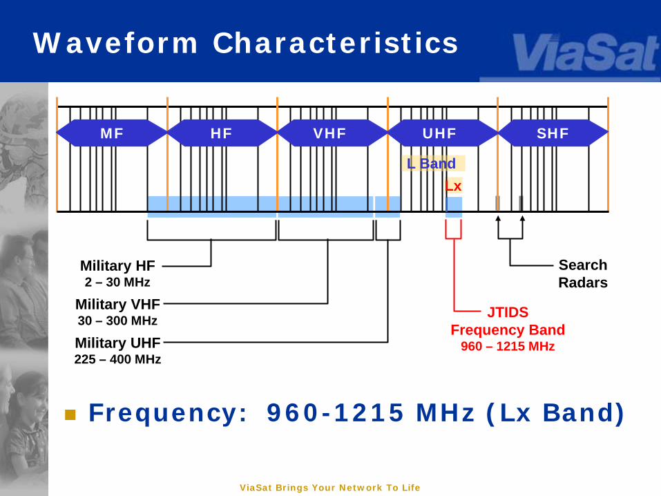
Waveform Characteristics
Frequency: 960-1215 MHz (Lx Band)
MF HF VHF UHF SHF
Military HF2 – 30 MHz
Military VHF30 – 300 MHz
Military UHF225 – 400 MHz
SearchRadars
JTIDSFrequency Band
960 – 1215 MHz
LxL Band
ViaSat Brings Your Network To Life
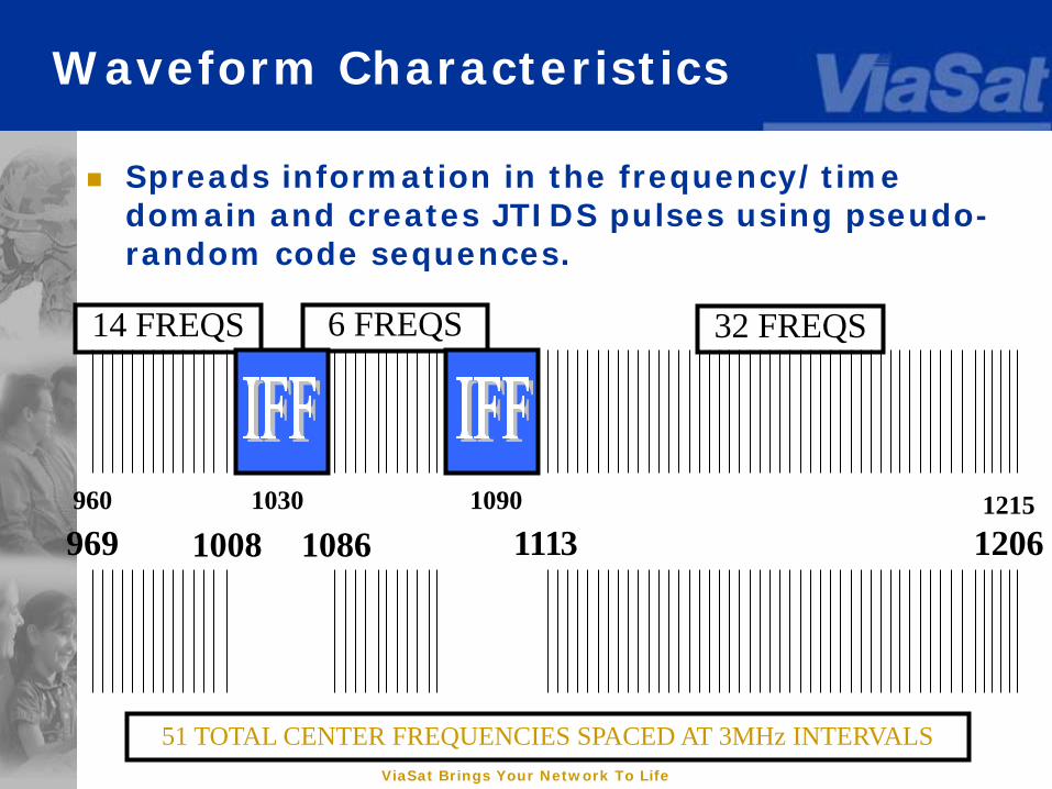
51 TOTAL CENTER FREQUENCIES SPACED AT 3MHz INTERVALS
1215
14 FREQS 6 FREQS 32 FREQS
960 1030 1090
969 1008 1086 1113 1206
Spreads information in the frequency/time domain and creates JTIDS pulses using pseudo-random code sequences.
Waveform Characteristics
ViaSat Brings Your Network To Life
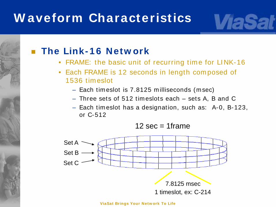
The Link-16 Network• FRAME: the basic unit of recurring time for LINK-16• Each FRAME is 12 seconds in length composed of
1536 timeslot– Each timeslot is 7.8125 milliseconds (msec)– Three sets of 512 timeslots each – sets A, B and C– Each timeslot has a designation, such as: A-0, B-123,
or C-512
12 sec = 1frame
7.8125 msec1 timeslot, ex: C-214
Waveform Characteristics
Set ASet B
Set C
ViaSat Brings Your Network To Life
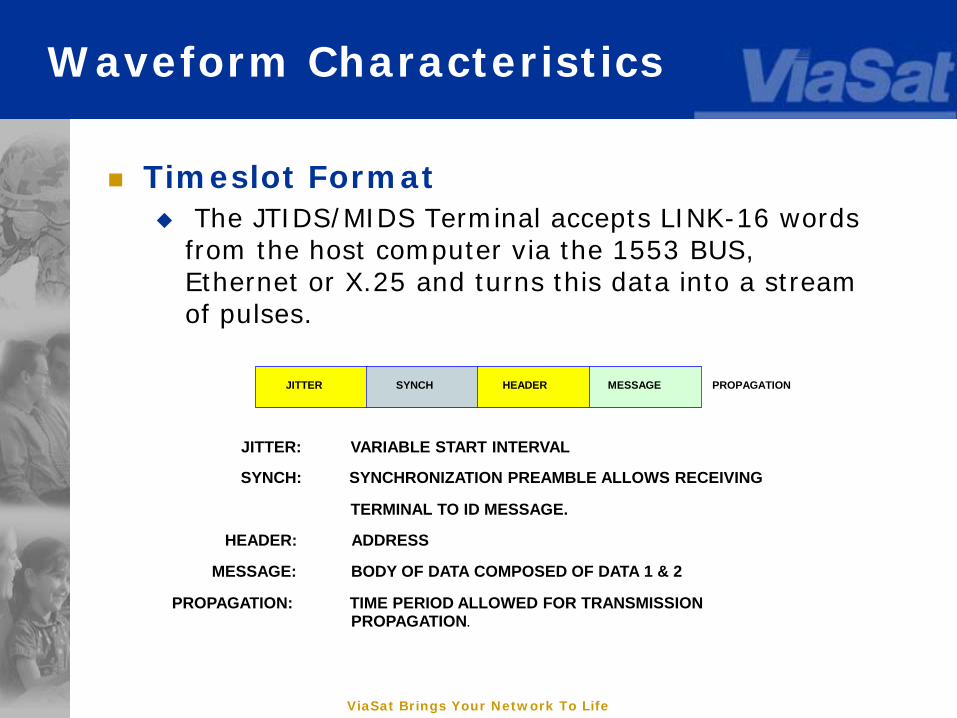
Timeslot Format The JTIDS/MIDS Terminal accepts LINK-16 words
from the host computer via the 1553 BUS, Ethernet or X.25 and turns this data into a stream of pulses.
JITTER: VARIABLE START INTERVAL
SYNCH: SYNCHRONIZATION PREAMBLE ALLOWS RECEIVING
TERMINAL TO ID MESSAGE.
HEADER: ADDRESS
MESSAGE: BODY OF DATA COMPOSED OF DATA 1 & 2
PROPAGATION: TIME PERIOD ALLOWED FOR TRANSMISSIONPROPAGATION.
JITTER SYNCH HEADER MESSAGE PROPAGATION
Waveform Characteristics
ViaSat Brings Your Network To Life
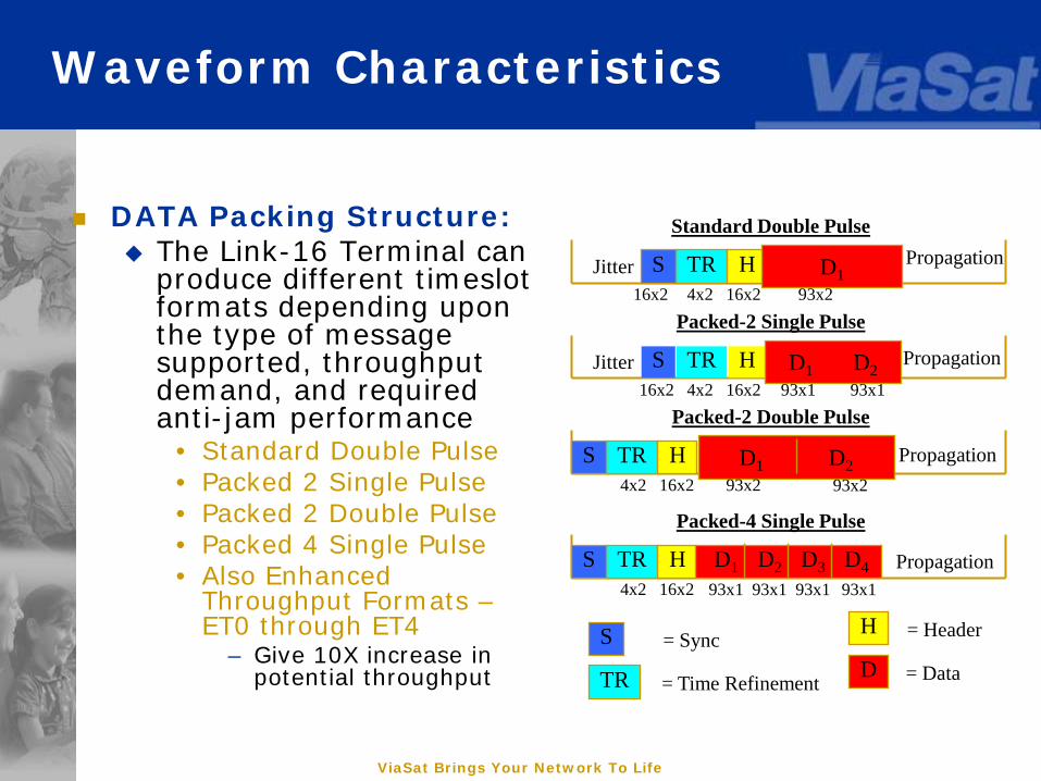
DATA Packing Structure: The Link-16 Terminal can
produce different timeslot formats depending upon the type of message supported, throughput demand, and required anti-jam performance
• Standard Double Pulse• Packed 2 Single Pulse• Packed 2 Double Pulse• Packed 4 Single Pulse• Also Enhanced
Throughput Formats –ET0 through ET4
– Give 10X increase in potential throughput
Jitter TR H D1S PropagationStandard Double Pulse
16x2 4x2 16x2 93x2
Jitter TR H D1 D2S Propagation
Packed-2 Single Pulse
16x2 4x2 16x2 93x1
TR H D1 D2S Propagation
Packed-2 Double Pulse
4x2 16x2 93x2
93x1
93x2
TR H D1 D2 D3 D4S Propagation
Packed-4 Single Pulse
4x2 16x2 93x1 93x1 93x1 93x1
S
TR
H
D= Sync
= Time Refinement
= Header
= Data
Waveform Characteristics
ViaSat Brings Your Network To Life
Net Entry Link-16 uses Specific messages to achieve
synchronization between terminals on the network
“COARSE SYNC” is achieved by terminals hearing J0.0 “Initial Entry” message transmitted in timeslot A-0.
• This ensures the terminal has the correct cryptographic key settings and has line-of-sight to the network NTR.
• Terminals in COARSE SYNC can receive but not transmit messages
“FINE SYNC” is then achieved by the passing of special messages called Round Trip Timing messages between the user terminal and the Network Time Reference.
Waveform Characteristics
ViaSat Brings Your Network To Life
Link 16 Features
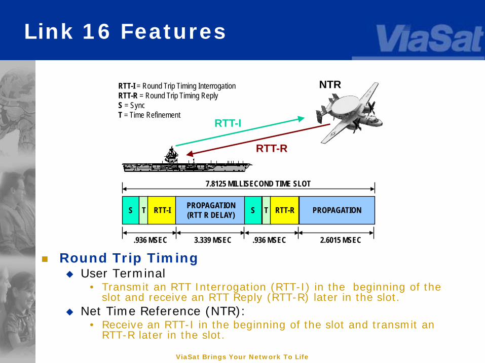
Round Trip Timing User Terminal
• Transmit an RTT Interrogation (RTT-I) in the beginning of the slot and receive an RTT Reply (RTT-R) later in the slot.
Net Time Reference (NTR):• Receive an RTT-I in the beginning of the slot and transmit an
RTT-R later in the slot.
RTT-I = Round Trip Timing InterrogationRTT-R = Round Trip Timing ReplyS = SyncT = Time Refinement
RTT-I
RTT-R
RTT-I RTT-RPROPAGATION(RTT R DELAY) PROPAGATIONS T S T
.936 MSEC 3.339 MSEC .936 MSEC 2.6015 MSEC
7.8125 MILLISECOND TIME SLOT
NTR
ViaSat Brings Your Network To Life
Link-16 Enhanced Usage Capabilities
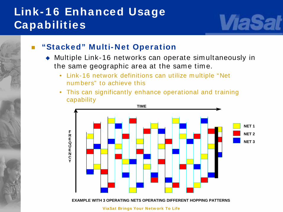
“Stacked” Multi-Net Operation Multiple Link-16 networks can operate simultaneously in
the same geographic area at the same time.• Link-16 network definitions can utilize multiple “Net
numbers” to achieve this• This can significantly enhance operational and training
capabilityTIME
FREQUENCY
NET 1
NET 2
NET 3
EXAMPLE WITH 3 OPERATING NETS OPERATING DIFFERENT HOPPING PATTERNS
ViaSat Brings Your Network To Life
Relay Transmitting received link 16 information in one or more
timeslots then later transmitting this information in other timeslots.
Relay modes:• Paired Slot Relay – Most basic type of relay. Contains 6 types of
relay functions.• Repromulgation Relay – Used by ground platforms when LOS does
not exist and a relayer is not available• Addressed Relay -- Used with specific needline participation groups.
Useful when multihop relay is required to meet the desired functional connectivity
Voice Link-16 supports dual-channel voice circuits
• Can run at 16Kbps or 2.4Kbps to support multiple national formats• Requires about ¼ slot utilization of the frame• Only works when the terminal is in the network
Access Modes Link 16 also has several access modes to exchange data and
increase the number of users.• Dedicated Access Mode – one slot, one transmitter• Contention Access Mode – one slot, multiple possible transmitters• Time Slot Reallocation – one slot transmitting from a “pool” of
transmitters
Link-16 Enhanced Usage Capabilities
ViaSat Brings Your Network To Life
Network Participation Groups: Link 16 uses these to allocate network capacity per
user based on the functions users would like to participate in. These NPGs act as virtual circuits to exchange specific assigned data.
A maximum 512 groups can defined, many are set for common use in functional areas:
• RTT (NPG 2 & 3)• Precise Participant Location and Identification (PPLI)
and Status (NPG 5 & 6)• Surveillance (NPG 7)• Electronic Warfare (NPG 10)• Weapons Coordination (NPG 8)• Air Control (NPG 9)• Fighter to Fighter (NPG 19, 20)• Secure Voice (NPG 12 & 13)
Link-16 Enhanced Usage Capabilities
ViaSat Brings Your Network To Life
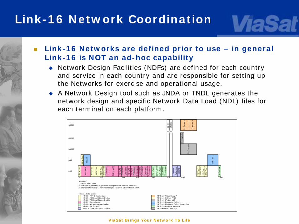
Link-16 Networks are defined prior to use – in general Link-16 is NOT an ad-hoc capability Network Design Facilities (NDFs) are defined for each country
and service in each country and are responsible for setting up the Networks for exercise and operational usage.
A Network Design tool such as JNDA or TNDL generates the network design and specific Network Data Load (NDL) files for each terminal on each platform.
Link-16 Network Coordination
Net 127
A/C (8)A/C (32)
Voice-A-R (112
~~ ~~
Net 126
NPG401 (48)
Net 121
Net 1
PPLI-A (32)
L/F (96)
F/F (160)
Net 0
RTT-B (8)
PPLI-B (16)
PPLI-B (96)
PPLI-B (31)PPLI-B-R (31)
SURV (42)
SURV-R (170)
SURV (8)SURV (16)
SURV (48)
SURV (8)SURV (8)
SURV (24)SURV-R (24)SURV (24)
SURV-R (24)
SURV (48)
SURV-R (48)
M/M
GT (60)
M/M
GT-R (60)
M/M
GT (24)
M/M
GT (8)
M/M
GT-R (8)
EW (30)
EW-R (30)
EW (36)
I-PPLI (8)I-PPLI-R (8)I-PPLI (8)
I-PPLI-R (8)
RMSG
(16)
NPG 3 - RTT-B (contention) NPG 12 - Voice Group A NPG 5 - PPLI and Status: Pool A NPG 14 - Indirect PPLI NPG 6 - PPLI and Status: Pool B NPG 16 - IP Over L16 NPG 7 - Surveillance NPG 19 - Fighter-to-Fighter NPG 8 - Weapons Coordination NPG 20 - Fighter-to-Fighter (contention) NPG 9 - Air Control NPG 29 - Residual Message NPG 10 - EW Electronic Warfare NPG 400/401 - Needline
Voice-A (112)
NPG16 (224)
SURV (128)
8 279 546 1530
Remarks:1. Default Net = Net 02. Numbers in parenthesis () indicate slots per frame for each slot block
658 862 970 1146
3. Dashed left border (---) indicates Relayed slot block (also noted on label)
Timeline Color Code:
ViaSat Brings Your Network To Life
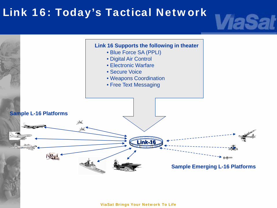
Link 16: Today’s Tactical Network
Link-16
Link 16 Supports the following in theater• Blue Force SA (PPLI)• Digital Air Control• Electronic Warfare• Secure Voice• Weapons Coordination• Free Text Messaging
Sample L-16 Platforms
Sample Emerging L-16 Platforms

ViaSat Brings Your Network To Life
Link-16 - Connecting Combat Systems
Link-16
FR Roland GE/IT/SP EF2000
F/A-18Hornet
THAADFR Rafale USAF F-16
F-15 A-E
Patriot
JTOAM/MCE
E-2 Hawkeye
AEGIS CG
F-14D Tomcat
F-15C Eagle
UK F-3Tornado
FAAD
E-3 Sentry
Joint STARS
Rivet Joint
Aircraft Carrier
IT Tornado
Airborne Laser
MIDS PlatformsJTIDS Platforms
JTIDS and MIDS Equipped platforms are fully interoperable

ViaSat Brings Your Network To Life
Link 16 Next Steps
There are around 5,000 Link-16 capable terminals in the world and the number will continue to grow However, the interest is now in dual- or multi-usage
terminals that give multiple datalink capabilities
Most users still consider Link-16 as a “backbone” communications technology
Link-16 Sustainment Programs funded beginning next year Frequency Remapping – enabling the number of
frequencies to be changed based on other needs
Enhanced Throughput – enabling more capacity per each timeslot’s worth of data
Modernized Crypto – enabling a cryptographic upgrade for more diverse security protocols
ViaSat Proprietary
MIDS Low Volume Terminals
ViaSat Brings Your Network To Life
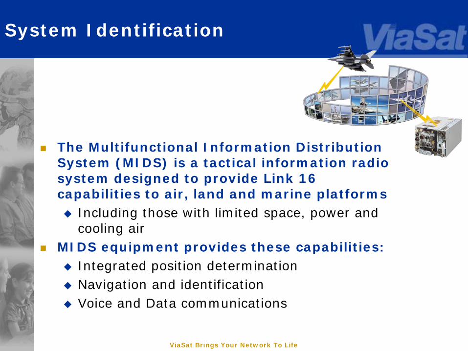
System Identification
The Multifunctional Information Distribution System (MIDS) is a tactical information radio system designed to provide Link 16 capabilities to air, land and marine platforms Including those with limited space, power and
cooling air MIDS equipment provides these capabilities:
Integrated position determination Navigation and identification Voice and Data communications
ViaSat Brings Your Network To Life
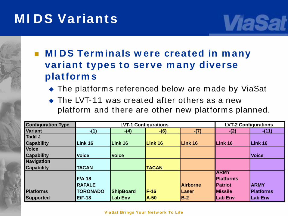
MIDS Variants
Configuration TypeVariant -(1) -(4) -(6) -(7) -(2) -(11)Tadil JCapability Link 16 Link 16 Link 16 Link 16 Link 16 Link 16VoiceCapability Voice Voice VoiceNavigationCapability TACAN TACAN
PlatformsSupported
F/A-18RAFALETORONADOE/F-18
ShipBoardLab Env
F-16A-50
Airborne LaserB-2
ARMY PlatformsPatriot MissileLab Env
ARMYPlatformsLab Env
LVT-1 Configurations LVT-2 Configurations
MIDS Terminals were created in many variant types to serve many diverse platforms The platforms referenced below are made by ViaSat The LVT-11 was created after others as a new
platform and there are other new platforms planned.

ViaSat Brings Your Network To Life
MIDS LVT(1) Terminal Identification
The MIDS Low Volume Terminal (LVT)-1 System (and variants) consists of two Line Replaceable Units (LRUs):
Main Terminal – referred to as the TERMINAL Remote Power Supply (RPS)
Three ancillary equipment LRUs: • AC RPS Power Adapter LRU (ACA)• DC RPS Power Adapter LRU (DCA)• High Power Amplifier Interface Assembly LRU (HIA)
ViaSat Brings Your Network To Life
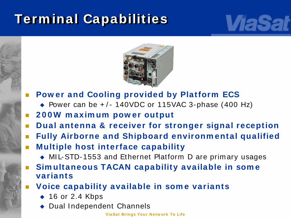
Terminal Capabilities
Power and Cooling provided by Platform ECS Power can be +/- 140VDC or 115VAC 3-phase (400 Hz)
200W maximum power output Dual antenna & receiver for stronger signal reception Fully Airborne and Shipboard environmental qualified Multiple host interface capability
MIL-STD-1553 and Ethernet Platform D are primary usages Simultaneous TACAN capability available in some
variants Voice capability available in some variants
16 or 2.4 Kbps Dual Independent Channels
ViaSat Brings Your Network To Life
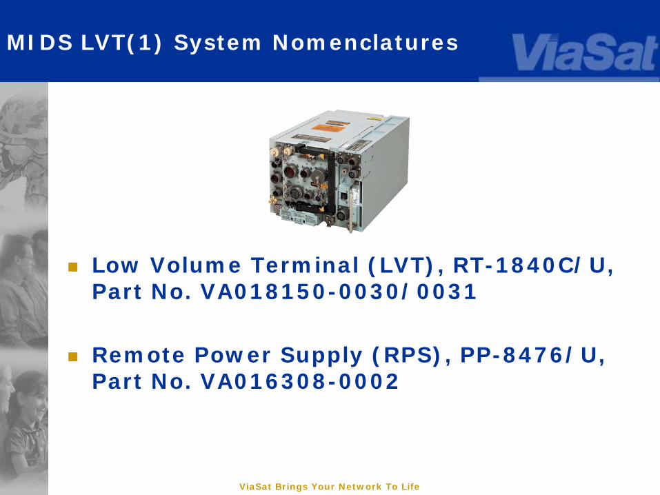
MIDS LVT(1) System Nomenclatures
Low Volume Terminal (LVT), RT-1840C/U, Part No. VA018150-0030/0031
Remote Power Supply (RPS), PP-8476/U, Part No. VA016308-0002
ViaSat Brings Your Network To Life
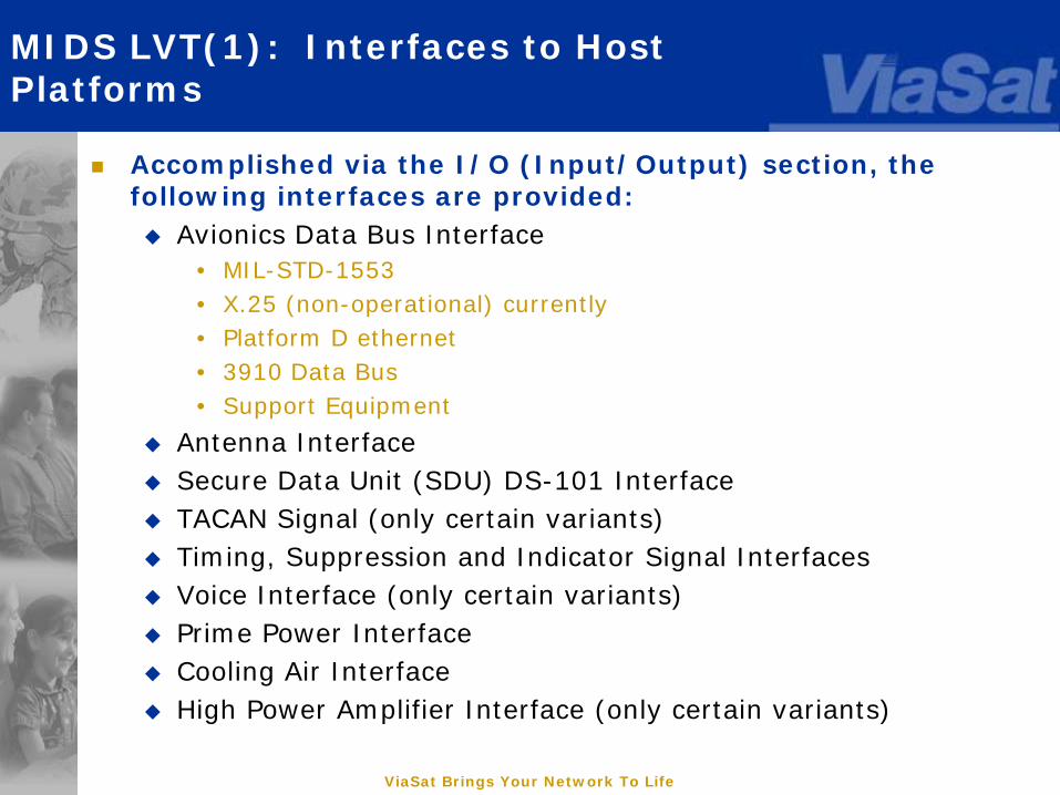
MIDS LVT(1): Interfaces to Host Platforms
Accomplished via the I/O (Input/Output) section, the following interfaces are provided: Avionics Data Bus Interface
• MIL-STD-1553• X.25 (non-operational) currently• Platform D ethernet• 3910 Data Bus• Support Equipment
Antenna Interface Secure Data Unit (SDU) DS-101 Interface TACAN Signal (only certain variants) Timing, Suppression and Indicator Signal Interfaces Voice Interface (only certain variants) Prime Power Interface Cooling Air Interface High Power Amplifier Interface (only certain variants)
ViaSat Brings Your Network To Life
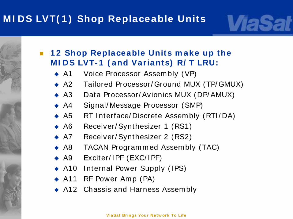
MIDS LVT(1) Shop Replaceable Units
12 Shop Replaceable Units make up the MIDS LVT-1 (and Variants) R/T LRU: A1 Voice Processor Assembly (VP) A2 Tailored Processor/Ground MUX (TP/GMUX) A3 Data Processor/Avionics MUX (DP/AMUX) A4 Signal/Message Processor (SMP) A5 RT Interface/Discrete Assembly (RTI/DA) A6 Receiver/Synthesizer 1 (RS1) A7 Receiver/Synthesizer 2 (RS2) A8 TACAN Programmed Assembly (TAC) A9 Exciter/IPF (EXC/IPF) A10 Internal Power Supply (IPS) A11 RF Power Amp (PA) A12 Chassis and Harness Assembly
ViaSat Brings Your Network To Life
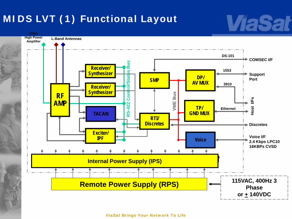
MIDS LVT (1) Functional Layout
Ethernet
DP/AV MUX
TACAN
Exciter/IPF
Receiver/Synthesizer
Receiver/Synthesizer
JTIDSHigh Power
Amplifier
RTI/Discretes
SMP
Voice Voice I/F2.4 Kbps LPC1016KBPs CVSD
COMSEC I/F
Hos
t I/F
s
Internal Power Supply (IPS)
Discretes
DS-101
L-Band Antennas
TP/GND MUX
3910
1553
VME
Bus
RS-
422
Con
trol
/Sta
tus
Bus
AIU
RFARF
AMP
Remote Power Supply (RPS)
SupportPort
115VAC, 400Hz 3 Phase
or + 140VDC
ViaSat Brings Your Network To Life
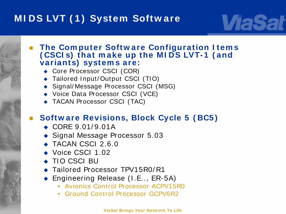
MIDS LVT (1) System Software
The Computer Software Configuration Items (CSCIs) that make up the MIDS LVT-1 (and variants) systems are: Core Processor CSCI (COR) Tailored Input/Output CSCI (TIO) Signal/Message Processor CSCI (MSG) Voice Data Processor CSCI (VCE) TACAN Processor CSCI (TAC)
Software Revisions, Block Cycle 5 (BC5) CORE 9.01/9.01A Signal Message Processor 5.03 TACAN CSCI 2.6.0 Voice CSCI 1.02 TIO CSCI BU Tailored Processor TPV15R0/R1 Engineering Release (I.E.., ER-5A)
• Avionics Control Processor ACPV15R0• Ground Control Processor GCPV6R2
ViaSat Brings Your Network To Life
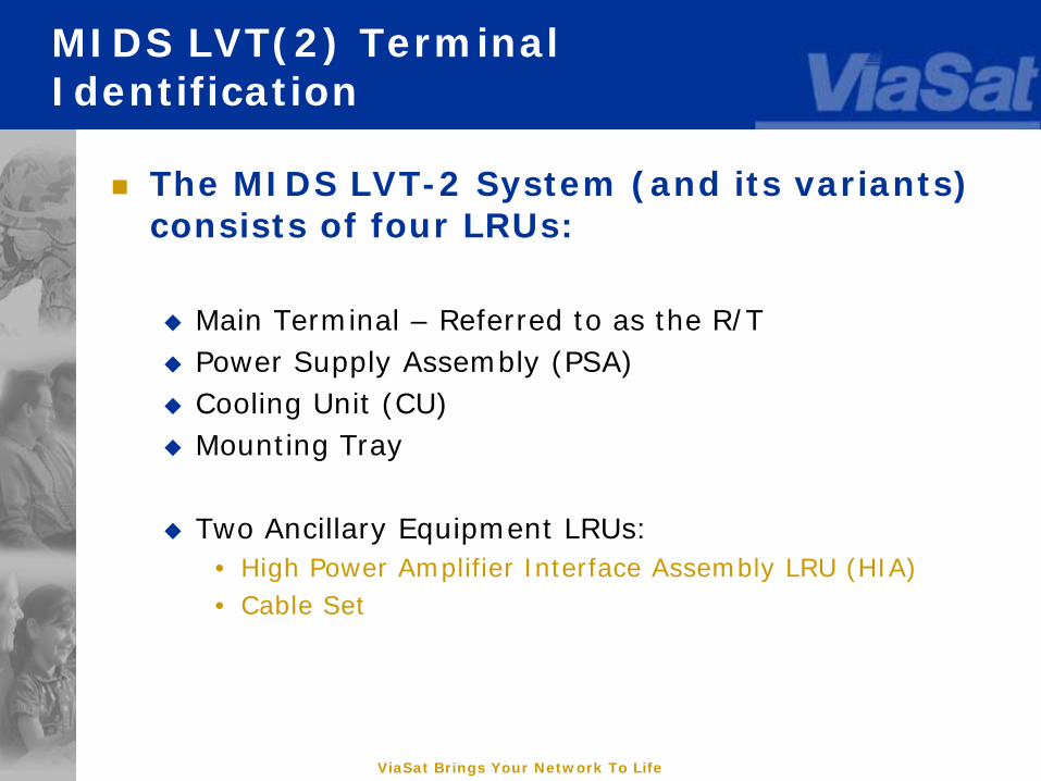
MIDS LVT(2) Terminal Identification
The MIDS LVT-2 System (and its variants) consists of four LRUs:
Main Terminal – Referred to as the R/T Power Supply Assembly (PSA) Cooling Unit (CU) Mounting Tray
Two Ancillary Equipment LRUs: • High Power Amplifier Interface Assembly LRU (HIA)• Cable Set
ViaSat Brings Your Network To Life
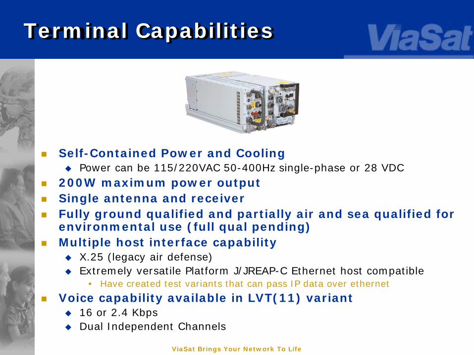
Terminal Capabilities
Self-Contained Power and Cooling Power can be 115/220VAC 50-400Hz single-phase or 28 VDC
200W maximum power output Single antenna and receiver Fully ground qualified and partially air and sea qualified for
environmental use (full qual pending) Multiple host interface capability
X.25 (legacy air defense) Extremely versatile Platform J/JREAP-C Ethernet host compatible
• Have created test variants that can pass IP data over ethernet
Voice capability available in LVT(11) variant 16 or 2.4 Kbps Dual Independent Channels

ViaSat Brings Your Network To Life
MIDS-LVT(2) System Nomenclatures
Radio Terminal Set AN/USQ-140(V)2(c) Receiver/Transmitter VA-019050-0030/31 PSA VA-016311-0002 Cooling Unit VA-016310-0003 Mounting Base VA-016309-0002

ViaSat Brings Your Network To Life
MIDS LVT(2): Interfaces to Host Platforms
Accomplished via the I/O (Input/Output) section, the following interfaces are provided: Avionics Data Bus Interface
• X.25 • Platform J / JREAP-C Ethernet• Support Equipment
Antenna Interface Secure Data Unit (SDU) DS-101 Interface Timing, Suppression and Indicator Signal Interfaces Voice Interface (only certain variants) Prime Power Interface Cooling Air Interface
ViaSat Brings Your Network To Life
MIDS LVT(2) Shop Replaceable Units
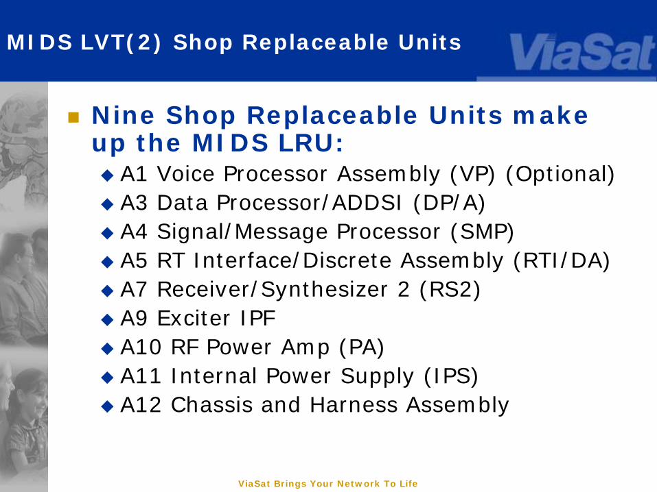
Nine Shop Replaceable Units make up the MIDS LRU: A1 Voice Processor Assembly (VP) (Optional) A3 Data Processor/ADDSI (DP/A) A4 Signal/Message Processor (SMP) A5 RT Interface/Discrete Assembly (RTI/DA) A7 Receiver/Synthesizer 2 (RS2) A9 Exciter IPF A10 RF Power Amp (PA) A11 Internal Power Supply (IPS) A12 Chassis and Harness Assembly
ViaSat Brings Your Network To Life
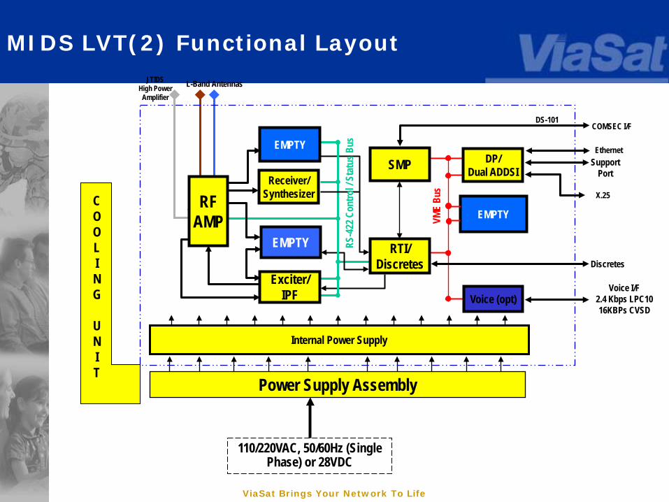
MIDS LVT(2) Functional Layout
Ethernet
EMPTY
Exciter/IPF
Receiver/Synthesizer
EMPTY
JTIDSHigh Power
Amplifier
RTI/Discretes
SMP
Voice (opt)
COMSEC I/F
Internal Power Supply
Discretes
DS-101
L-Band Antennas
VME
Bus X.25AIU
RFA
RFAMP
Power Supply Assembly
SupportPort
RS-4
22 C
ontro
l / St
atus
Bus
110/220VAC, 50/60Hz (Single Phase) or 28VDC
DP/Dual ADDSI
Voice I/F2.4 Kbps LPC1016KBPs CVSD
EMPTYCOOLING
UNIT
ViaSat Brings Your Network To Life
MIDS LVT(2) System Software
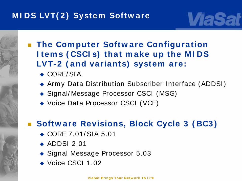
The Computer Software Configuration Items (CSCIs) that make up the MIDS LVT-2 (and variants) system are: CORE/SIA Army Data Distribution Subscriber Interface (ADDSI) Signal/Message Processor CSCI (MSG) Voice Data Processor CSCI (VCE)
Software Revisions, Block Cycle 3 (BC3) CORE 7.01/SIA 5.01 ADDSI 2.01 Signal Message Processor 5.03 Voice CSCI 1.02
ViaSat Brings Your Network To Life
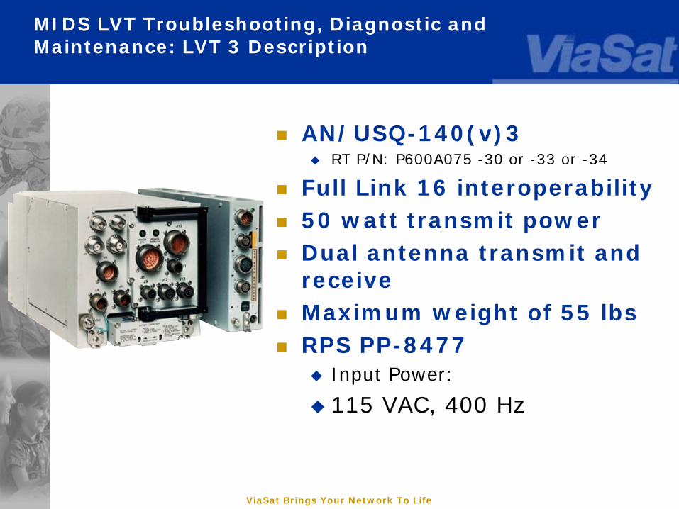
AN/USQ-140(v)3 RT P/N: P600A075 -30 or -33 or -34
Full Link 16 interoperability 50 watt transmit power Dual antenna transmit and
receive Maximum weight of 55 lbs RPS PP-8477
Input Power:
115 VAC, 400 Hz
MIDS LVT Troubleshooting, Diagnostic and Maintenance: LVT 3 Description
ViaSat Brings Your Network To Life 49
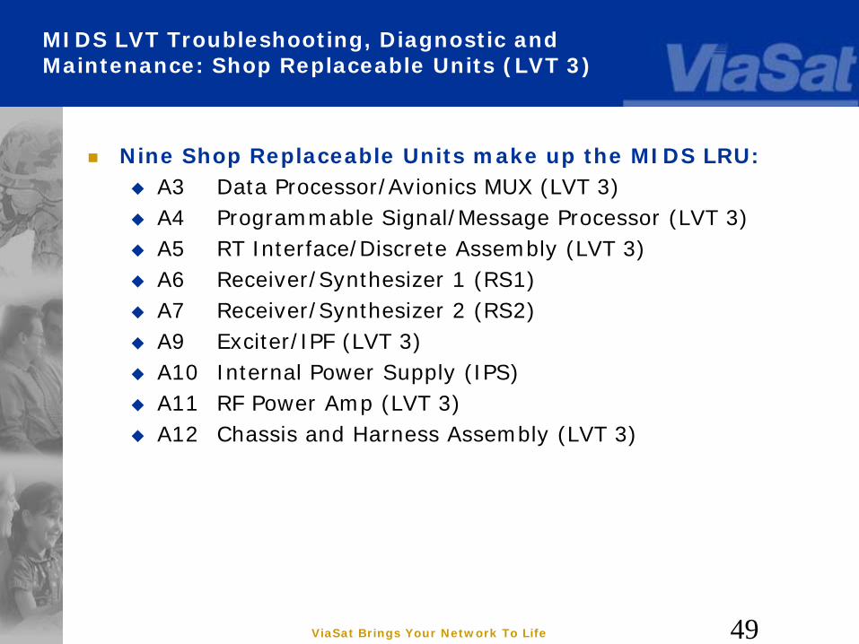
MIDS LVT Troubleshooting, Diagnostic and Maintenance: Shop Replaceable Units (LVT 3)
Nine Shop Replaceable Units make up the MIDS LRU: A3 Data Processor/Avionics MUX (LVT 3) A4 Programmable Signal/Message Processor (LVT 3) A5 RT Interface/Discrete Assembly (LVT 3) A6 Receiver/Synthesizer 1 (RS1) A7 Receiver/Synthesizer 2 (RS2) A9 Exciter/IPF (LVT 3) A10 Internal Power Supply (IPS) A11 RF Power Amp (LVT 3) A12 Chassis and Harness Assembly (LVT 3)
ViaSat Proprietary
Small Tactical Terminal
ViaSat Brings Your Network To Life
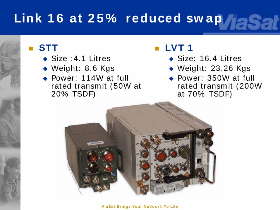
Link 16 at 25% reduced swap
LVT 1 Size: 16.4 Litres Weight: 23.26 Kgs Power: 350W at full
rated transmit (200W at 70% TSDF)
STT Size :4.1 Litres Weight: 8.6 Kgs Power: 114W at full
rated transmit (50W at 20% TSDF)
ViaSat Brings Your Network To Life
Design Overview
STT is designed to be a low cost, low volume, data link terminal capable of running Link 16 or UHF LOS Waveforms
STT is designed to meet the needs of users who have space and weight constraints but want to take advantage of the information available on Link 16 and/or Tactical UHF Networks Situational Awareness and Surveillance to the Tactical Edge Command and Control with Disadvantaged Users Blue Force Position and Status Reports Interoperable with JTIDS and MIDS Radios Interoperable with UHF LOS (MIL-STD-188-220 B/C/D) with
PRC-117, PRC-152, ARC-210 (RT-1824), Improved Data Modem (IDM)
ViaSat Brings Your Network To Life
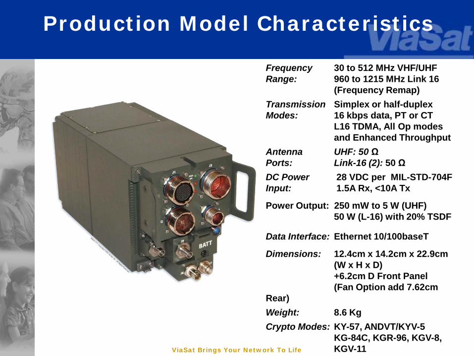
Production Model Characteristics
Frequency 30 to 512 MHz VHF/UHFRange: 960 to 1215 MHz Link 16
(Frequency Remap)Transmission Simplex or half-duplexModes: 16 kbps data, PT or CT
L16 TDMA, All Op modesand Enhanced Throughput
Antenna UHF: 50 ΩPorts: Link-16 (2): 50 ΩDC Power 28 VDC per MIL-STD-704FInput: 1.5A Rx, <10A Tx
Power Output: 250 mW to 5 W (UHF)50 W (L-16) with 20% TSDF
Data Interface: Ethernet 10/100baseT
Dimensions: 12.4cm x 14.2cm x 22.9cm(W x H x D)+6.2cm D Front Panel (Fan Option add 7.62cm
Rear)Weight: 8.6 KgCrypto Modes: KY-57, ANDVT/KYV-5
KG-84C, KGR-96, KGV-8,KGV-11
ViaSat Brings Your Network To Life
Schedule
Track 1 prototypes in final integration Completed prototypes available starting
Dec 08 Total of 6-10 units planned
Track 2 production schedule: Preliminary Design Review – Jan 2009 Critical Design Review – Apr 2009 First Pre-production Units available – 4thQ
2010 (CY) Completion of Qual & Certs – 3Q 2010

ViaSat Brings Your Network To Life
MilCIS 2009 Link 16/MIDS Overview
Mr. Tim Trudeau ViaSat
ViaSat Frontline Immediate Response and Support Team Telephone 1-800-MIDS-HLP
(1-800-643-7457) Email [email protected]