· pdf filehyperion 16” f/7.3 astrograph operating instructions thank you for purchasing...
TRANSCRIPT

Hyperion16” f/7.3 Astrograph
Operating Instructions
Thank you for purchasing a Hyperion telescope. You now own the most state-of-the-art astrograph available. In addition to providing a large aberration-free flat field, the Hyperion comes standard with a wealth of features.
This instruction manual will describe in detail the proper use of the Hyperion and its many features. Please note the Warnings given in the next section in order to avoid damaging your Hyperion.
Table of Contents
Warnings 2Overview 5Setup After Shipping 10Collimation 12Telescope Control Panel 16Telescope Control Software 20Appendix 27Specifications 30Contact Information 30

Warnings
Things Not to Touch
There are two adjustments made when the telescope is assembled and tested that should not be adjusted by the user. First is the secondary mirror spacing. This is adjusted by a nut located under the cover plate on the spider hub.
Don’t go there
Second is the corrector lens tip/tilt adjustment. This is located about halfway down the outside of the primary baffle tube.
Don’t go there

Caution
Collimation Bolts
The primary mirror assembly (including the mirror cell, mirror, baffle tube, and corrector lenses) is held in place by the primary mirror collimation screws on the telescope back plate. Do not loosen these screws too much or the whole assembly will fall off (this is a bad thing), or more likely one screw will pop loose and you will have to take off the back plate to reattach it. When collimating the telescope, make only small adjustments as the telescope was collimated before shipping and should require only a little tweaking.
Same goes for the secondary assembly. It is held in place by its collimation screws. Again, don’t loosen these too much or the assembly can become detached (another bad thing). Make only small adjustments to the collimation screws. More details are in the section on collimation.

Focuser and Instrument Rotator
The focuser and instrument rotator are designed to be moved electronically with their motors. Do not attempt to move these units by hand. If for some reason is it necessary to move the focuser drawtube manually, you may remove the motor and turn the focus knob by hand. Note that there is a tension knob on the bottom of the focuser. When the focuser motor is attached and in use, the tension knob should be loose.
The instrument rotator should never be moved by hand. Manual rotation of the focuser can be achieved by loosening the lock collar on the Feathertouch focuser. Note that the indexing of the rotator is independent of the position of the focuser, so adjusting the focuser’s rotation from its initial position is not necessary.
Telescope Overview
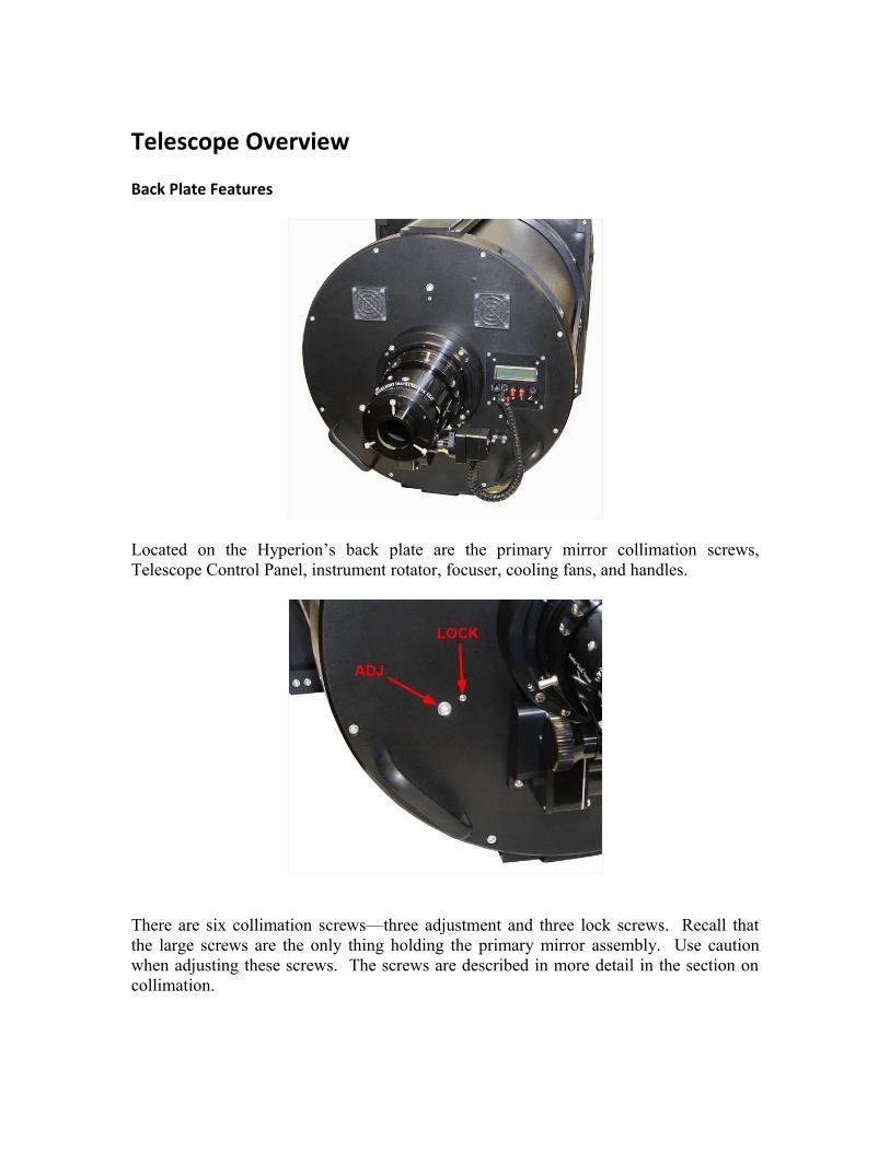
Back Plate Features
Located on the Hyperion’s back plate are the primary mirror collimation screws, Telescope Control Panel, instrument rotator, focuser, cooling fans, and handles.
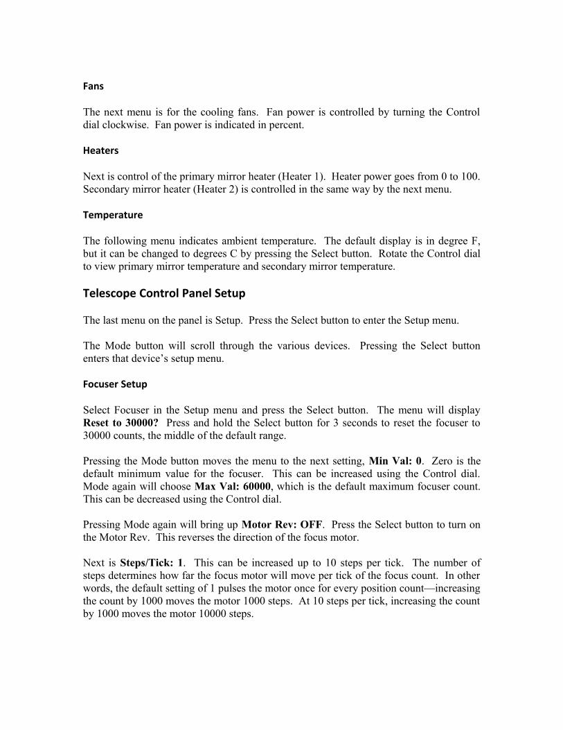
There are six collimation screws—three adjustment and three lock screws. Recall that the large screws are the only thing holding the primary mirror assembly. Use caution when adjusting these screws. The screws are described in more detail in the section on collimation.

The Telescope Control Panel is the brains of the operation. This panel features an LCD display and controls the instrument rotator, main Hyperion focuser, an optional piggyback instrument focuser, cooling fans, and dew heaters. These features can also be controlled remotely from a computer using the Telescope Control Software. More details are in the section on the Telescope Control Panel and Telescope Control Software.
The high-precision instrument rotator allows accurate positioning of the camera for framing a target or finding a guidestar. It can be controlled through either the Telescope Control Panel or the Telescope Control Software.

Dual cooling fans move filtered air around the primary mirror and through the optical tube to accelerate thermal stabilization of the optics. This reduces the effect of tube currents which can degrade seeing conditions.
The Hyperion uses a 3.5” Feathertouch Focuser for precise focusing. The focuser is automated using Starizona’s MicroTouch autofocuser. The Feathertouch has 4.5” (115mm) of focus travel and tick marks on the side of the focuser drawtube indicate the current travel of the focuser in mm. The Hyperion has 6.9” (175mm) of backfocus from the racked-in focuser drawtube to the focal plane. This distance does not include the thickness of the focuser adapter, which varies by camera, but is approximately 1” (25mm) thick.
There are two handles on the back plate as well to help make it easier to transport and mount the telescope. These handles are also convenient for tying off camera cables; just be sure to leave enough slack in the cables to allow for movement of the instrument rotator.

Other Features
The Hyperion features top and bottom Losmandy-style dovetail plates. The top dovetail is ideal for piggybacking an optional guidescope or other wide-field instrument. The dovetail will accept standard Losmandy accessories such as mounting rings and allows you to balance the telescope by sliding the piggybacked instrument front to back. When adding a second instrument, consider not only the weight of the instrument but also the leverage due to the distance from the mount. This may make some instruments impractical for some mounts. The distance between dovetails is 20.4” (518mm) and each dovetail is 16” (406mm) long.
Note that the bottom dovetail is 6” (152mm) wide overall to add support to the telescope. This width is compatible with the Paramount Versaplate. For use with an Astro-Physics mount, the DOVELM162 saddle plate is required as the standard Losmandy-style DOVELM2 knobs will interefere with the dovetail.

The secondary mirror is collimated with three screws attached to the triangular plate on the spider assembly. A reminder that these three screws are the only thing holding the secondary mirror assembly in place. Use caution when adjusting these screws. These screws are described in more detail in the section on collimation.
The Hyperion has both primary and secondary mirror dew heaters to prevent moisture from building up. The heaters can be controlled through either the Telescope Control Panel or the Telescope Control Software.
Unique to the Hyperion is the ability to control all electronic features wirelessly. This is done through the wireless control box. The control box plugs into your computer via a USB cable and talks wirelessly to the Hyperion up to 300 feet away.

Setup After Shipping
Installing the Focuser
To keep the shipping dimensions as small as possible, the Hyperion 16 ships without the Feathertouch Focuser attached. Installation is easy.
Begin by racking the focuser drawtube out a few inches. This will prevent difficulty threading the focuser on due to the narrow clearance inside the telescope.
Remove the dust cap from the rotator mount and thread the focuser into the rotator. Once fully threaded in, lock the focuser in place with the set screw in the side of the rotator mount.
After mounting the focuser, you can attach the MicroTouch focus motor. The motor simply mounts on the right side (viewed from the back) of the focuser pinion. When sliding the motor on, make sure the motor gear engages with the gear on the focuser. Lock the motor in place with the set screw on the motor's clamp ring. The motor can be in any orientation, but the most convenient is to have the cable plug facing the control panel on the backplate.
Removing the Dust Cover
The large dust cover that protects the primary mirror requires a little trick to remove it from inside the truss poles as it only just clears the secondary mirror assembly.
The primary mirror dust cover attaches to the front of the truss plate (the large square plate that the truss poles are mounted to) with two thumb screws. Remove these thumb screws to release the dust cap. Slide the cap forward until it clears the primary baffle tube.

Now tilt the cover horizontally by tipping the top toward the primary mirror and the bottom toward the secondary mirror. Before you get to the horizontal position, you will see that the cover would bump into the secondary baffle. Slide the cover back into the opening in the truss plate until the opposite side will clear the secondary baffle.
Be careful not to hit the wireless communications board inside the top of the tube when doing this.

Finally, lift the cover upward and forward out of the truss plate opening, and bring it out between two of the truss poles. Reverse the procedure to put the cover back in place when finished observing.
Collimation
While the Hyperion was collimated and tested before being shipped, it likely will need some slight adjustment after arrival. This section describes the full procedure for properly collimating the Hyperion. The adjustments should be made in the order outlined below.
Secondary Mirror Tilt
This is best evaluated using an optional laser collimator. Use the included 2” end cap for the Feathertouch focuser to attach the laser collimator.
Secondary mirror centering is unlikely to be necessary, but the steps below describe the method for centering if needed.
The secondary mirror has a centering mark on it. If any adjustment needs to be made to the mirror centering, do not adjust the outer screws on the spider vanes (where they connect to the front ring). The spider vanes have been set square when the telescope was assembled, and this gives perfect diffraction spikes on bright stars. Any misalignment will result in doubled diffraction spikes.

Instead, to adjust the centering of the secondary, use the four small set screws located at 45-degrees between each spider vane on the spider hub. These screws push against a tapered cylinder inside the hub and move the position of the entire secondary assembly. They must be tight after any adjustment is made.
With the laser mounted in the focuser, the red dot should hit the secondary mirror inside the center of the center mark. Adjust the set screws as described above if necessary.
Now, look toward the primary mirror. Look for the reflection of the secondary mirror in the primary mirror. You should see the laser being emitted from the bottom of the laser collimator. You should also see that the beam bounces off the secondary and returns right on itself. If you see two red spots on the collimator, the beam is not returning exactly onto itself and you need to adjust the tilt of the secondary mirror.

This adjustment is done using the secondary collimation bolts. In order to adjust the secondary mirror tilt, begin by loosening one of the collimation bolts (say, ¼ turn), then tighten one or both of the other bolts. Remember that the bolts are the only thing holding the secondary mirror assembly, so do not loosen them too much. Once the laser beam is returning exactly on itself, the secondary mirror is collimated. Be sure the collimation screws are snug when finished.
Star Test
To precisely collimate the Hyperion, a star test is required. Before beginning the star test, allow the telescope to thermally stabilize for at least 30 minutes, preferably with the cooling fans running. This eliminates any thermal distortion of the star image, which can take on the same appearance as collimation error.
The star test is best done with a camera, while looking at the images on the computer screen to evaluate the collimation. Aim the telescope to a moderately bright star. It is important that the star is well centered in the field. Begin the star test by defocusing the telescope. You will see a donut-shaped star image. If the telescope is out of collimation, you will see the central obstruction is not concentric with the outer edge of the star image (the donut hole will appear offset).

If adjustment is necessary, begin by loosening one of the collimation screws. Begin by trying a small turn of the screw, say 1/8 turn, and begin by tightening the screw to bring the mirror back. If this adjustment is the wrong way, return the adjustment screw to its initial position and try one of the other screws.
Once the out-of-focus star image is concentric, the secondary mirror is collimated.
Adjustment of the primary mirror is done using the six screws on the back plate of the telescope. The three smaller screws are lock screws, holding the mirror in place. The three larger screws are the adjustment screws. These screws have springs on the them inside the telescope, pushing on the primary mirror cell. Tightening them pulls the mirror back; loosening them pushes the mirror forward.
Remember that the large screws are the only thing holding the primary mirror assembly in place, so do not loosen them too much. Very little adjustment should be required.
Bring the telescope to focus. Take a single frame exposure, about 5-10 seconds long, at 1x1 binning (full resolution). Examine the corners of the image at 100% magnification. The stars should appear equally round in each corner. If using a program such as MaxIm DL, you can make use of inspection tools to measure the average size of the stars in each corner of the image.

If the star sizes are not equal, fine tuning is possible by making very small adjustments to the primary mirror.
Begin by loosening one of the (small) collimation lock screws about 1/8 turn. Then tighten the (large) adjustment screw.
Take another exposure. If needed, refocus the telescope. If things have improved, continue until the stars are sharp across the full field. If things got worse, return the adjusted pair of screws to their original position and select a different set of screws. Your Hyperion is now perfectly collimated and ready for imaging!
Telescope Control Panel
The integrated Telescope Control Panel operates all the electronic features of the Hyperion. The controls on the panel consist of a Power button, Mode button, Select button, and Control dial. There are two focus motor plugs and one 12v power plug.
Start by connecting the included focus motor cable. The main focuser plug is the one on the right. Connect this to the MicroTouch motor on the Feathertouch focuser.

To operate the control panel, begin by plugging in the 12v power supply. You can lock down the cable with the clamp below the panel.
Press the Power button to turn the panel on. The cooling fans will run for a couple seconds when power is first applied.
The default display on the LCD screen is for control of the main focuser motor. Turning the Control dial will rack the focuser in or out. The screen displays both the requested focus position and the current position. Turning the dial clockwise moves the focus drawtube out, with the focuser position count increasing. Turning the dial counter-clockwise decreases the position count and moves the focuser in. See the section below on Setup for instructions on resetting the focuser position and reversing the direction of travel.
Pressing the Mode button will scroll the menu on the LCD screen through the various electronic features.
Guider
First is the Guider focuser, for an optional MicroTouch focuser on an optional piggyback instrument.
Rotator
Next is the rotator control. The rotator can be indexed in any position—see the section below on Setup. Turning the Control dial clockwise turns the rotator clockwise. Position angle of the rotator increases clockwise.
Fans
The next menu is for the cooling fans. Fan power is controlled by turning the Control dial clockwise. Fan power is indicated in percent.
Heaters
Next is control of the primary mirror heater (Heater 1). Heater power goes from 0 to 100. Secondary mirror heater (Heater 2) is controlled in the same way by the next menu.
Temperature
The following menu indicates ambient temperature. The default display is in degree F, but it can be changed to degrees C by pressing the Select button. Rotate the Control dial to view primary mirror temperature and secondary mirror temperature.
Telescope Control Panel Setup
The last menu on the panel is Setup. Press the Select button to enter the Setup menu.
The Mode button will scroll through the various devices. Pressing the Select button enters that device’s setup menu.
Focuser Setup
Select Focuser in the Setup menu and press the Select button. The menu will display Reset to 30000? Press and hold the Select button for 3 seconds to reset the focuser to 30000 counts, the middle of the default range.
Pressing the Mode button moves the menu to the next setting, Min Val: 0. Zero is the default minimum value for the focuser. This can be increased using the Control dial. Mode again will choose Max Val: 60000, which is the default maximum focuser count. This can be decreased using the Control dial.
Pressing Mode again will bring up Motor Rev: OFF. Press the Select button to turn on the Motor Rev. This reverses the direction of the focus motor.
Next is Steps/Tick: 1. This can be increased up to 10 steps per tick. The number of steps determines how far the focus motor will move per tick of the focus count. In other words, the default setting of 1 pulses the motor once for every position count—increasing the count by 1000 moves the motor 1000 steps. At 10 steps per tick, increasing the count by 1000 moves the motor 10000 steps.

Lastly is Temp Comp: Ambient. You can set the focuser’s temperature compensation mode to use either ambient, primary mirror, or secondary mirror temperature for reference.
Guider Setup
This works exactly the same as the Focuser Setup above, but controls the optional second MicroTouch focuser on a piggybacked instrument.
Rotator Setup
The first selection is Reset to 0.0? Press and hold the Select button for 3 seconds to reset the rotator position angle to 0.0. This initializes the position of the rotator. Normally this would be set with the camera oriented orthogonal to the north-south line in the sky and with the guide CCD above (north of) the main CCD.
Next is Motor Rev: ON. This is the default and turns the rotator clockwise when the Control dial is turned clockwise and when the position angle increases. Press the Select button to turn the motor reverse off.
Finally there is Wrap: 0. This sets the wrap limit on the rotator. It is set in number of degrees that the rotator will turn past 180 degrees. You can dial in any number up to 360. The default is zero, meaning the rotator will never turn more than 180 degrees before taking the other direction to a given angle. This prevents cord wrap issues with the focus motor and camera cables.
Temperature Compensation Setup
The first setting in the Temp Comp menu allows you to turn on temperature compensation and to select which device to use. Pressing the Select button turns the temperature compensation on or off. Turning the Control dial selects the main focuser, guider focuser, or both.
Pressing Mode switches to Learning mode. Turning this on begins the procedure for the focuser to learn the temperature compensation characteristics of the Hyperion. Again, each device can be selected with the Control dial.
Finally, there is Setup: Offsets. Here you can select ambient, primary, and secondary temperatures and input offsets from the measured temperature to the actual temperature for more precision. For example, if the ambient temperature is reading 75 degrees on the control panel, and you know the actual temperature is 72 degrees, you can dial in a -3.0 degree offset in this menu.

Telescope Control Software
The Hyperion control software lets you operate all the telescope’s electronic features remotely.
Power up the Hyperion telescope control panel and start the Hyperion software. Make sure the USB wireless box is plugged into the computer and press Connect.
The default window is for Main Focuser control. Once connected, you should see the current focuser position displayed. You can manually change the focuser position by clicking and holding on either the up or down arrows to the right of the position display.
To send the focuser to a given position, type the desired position into the Target Position box and press Goto. Note that the focuser has a range of 0-60000 counts.
To index the focuser to a given position, enter that number in the Target Position box and press Reset to Target Position. This will set the current position to the targeted number.
Under Favorite Locations you can define up to three preset focus positions.
The Guide Scope Focuser window works identically to the Main Focuser window but controls an optional piggyback instrument.

The Instrument Rotator window allows you to control the position of the Hyperion’s instrument rotator. The current position is shown in the Position display.
By pressing the left or right arrows, you can manually move the rotator to any angle.
To send the rotator to a given position, type the desired angle (0-359) into the Target Position box and press Goto.
To index the rotator to a given position, enter that number in the Target Position box and press Reset to Target Position. This will set the current position to the targeted angle.
Checking the Wrap Limit box will enable the wrap limit set in the Setup window (see below).
As with the focuser, you can preset up to three Favorite Locations.

The Fan Control window displays the current fan power level. Pressing the up or down arrows will manually increase or decrease the fan speed in 1% increments. You can also select a predefined power level using the % buttons to the right of the arrows.
The Temperature Control window has three tabs. The first, Temperatures, shows the current ambient temperature as well as the current temperatures of the primary and secondary mirrors. The mode can be changed from degrees F to degrees C.
The Heaters tab allows you to manually set the power for each heater. Heater 1 controls the primary mirror heater. Heater 2 controls the secondary mirror heater. The up and down arrows will increase or decrease the heater power in 1% increments. Preset heater powers can be set using the % buttons to the right of the arrows.

The Temperature Compensation tab allows you to control the temperature compensation parameters. There are two ways to set the temperature compensation.
You can click on the Snapshot button to capture the current temperature data. Then, at a later point in the night, click on the Comp. Immediate button. This will calculate the temperature differential between the current conditions and those when you clicked the Snapshot button earlier. The temperature compensation will be based on this differential.
Alternatively, you can let the Hyperion learn the correct temperature compensation characteristics. Check the Learn box. The current temperature information is recorded. At a later time, uncheck the Learn box and the differential will be calculated.
Check the Enabled box to activate temperature compensation.

The Setup window has four tabs for setting parameters for the various features.
The Focuser tab lets you select Minimum and Maximum focuser values. The default range of the focuser is 0-60000 counts. Changing these values will restrict the motion of the focuser.
Steps per Tick can be set, changing the resolution of the focuser. The default is 1 step per tick, meaning the focuser moves one step for every one number increment of the display. Increasing this to 2, for example, means the focuser moves two steps for each number increment in the display.
Compensate On allows you to select whether the temperature compensation is based on the ambient temperature, primary mirror temperature, or secondary mirror temperature. Default is ambient temperature.
The Reverse checkbox reverses the direction of motion of the focuser.
The Guider tab works exactly like the Focuser tab.

The Rotator tab allows you to set a Wrap Limit for the instrument rotator. The wrap limit is defined as the number of degrees past 180. For example, setting the wrap limit to 15 would allow the rotator to go 15 degrees past 180 degrees before reversing and taking the other direction around to a given position.
The Reverse checkbox reverses the direction of the motion of the rotator.
The Temperature tab allows for setting the temperature characteristics of the system.
If you know the actual temperature is different from the ambient temperature reading, for example, you can program in an offset. If the ambient temperature reads 75 degrees and you know it is actually 72 degrees, you can program in a -3.0 degree offset.
The same can be done for primary and secondary mirror temperatures.
Temp. Comp. Devices allows you to select whether the main focuser, guide scope focuser, or both and operating when temperature compensation is active.
Learn Devices allows you to select whether the main focuser, guide scope focuser, or both are active when the system is learning the temperature compensation properties.

Updating the Firmware
You can download the latest version of the Hyperion firmware from the Hyperion product page on Starizona.com. The downloaded file will be in the .bin format and will include the version number in the filename.
Launch the Hyperion Flash Loader program.
Click on Select File and navigate to the .bin file you downloaded. Click OK.
On the Hyperion control panel on the back of the scope, press and hold both the Mode and Select buttons. While holding these buttons, press the power button, then release all three buttons. The Hyperion will power up in Program Mode, indicated by PROG MODE on the control panel display. The fans also run continuously while inProgram Mode.
You then have 30 seconds to click Program in the Hyperion Flash Loader program. If you fail to select Program within the allotted time, the telescope will leave the program mode.
When successful, you will see the telescope being programmed in the Flash Loader program. When finished you can close the program.
Recycle the Hyperion’s power and note the version number displayed when the control panel boots up. It should match the version of the firmware you just uploaded.

APPENDIX
Using FocusMax to Autofocus
FocusMax is freeware that controls the Hyperion’s focuser, allowing automated focusing using either MaxIm DL or CCDSoft camera control software.
After launching FocusMax for the first time, you will need to select the Hyperion Main Focus Driver from the pulldown menu. Once connected to the focuser, you will need to train FocusMax. This is easy and actually pretty fun to watch!
Point the telescope to a moderately bright star, around 4th magnitude and near the zenith. Use the Telescope Control Panel or Hyperion software to roughly focus the telescope manually.
Select Wizard from the top menu in FocusMax and choose First Light. FocusMax will rearrange the software windows so you can see everything that is about to happen. Follow the directions to begin.
FocusMax will drive the telescope out of focus to determine the focus range. It will then build a V-Curve, which characterizes the focusing system. Lastly, FocusMax will focus the telescope. Once focused, look for the 1/2FD (Half Flux Diameter) number given in the main FocusMax window. This is an indication of the size of the focused star.

Many factors affect the Half Flux Diameter value that FocusMax returns. With a long-focal-length telescope like the Hyperion, it is primarily a function of seeing conditions. A camera with typical 9-micron pixels has a resolution of 0.73 arcseconds per pixel with the Hyperion. If the seeing is around 2.0 arcseconds, for example, the Half Flux Diameter will be around 2.8. Over time, you will get a feel for what seeing is like at your location and the Half Flux Diameter can be a good indicator of whether a given night is better than average for imaging. Seeing below 2.0 arcseconds is considered very good.
After running the First Light Wizard, you can close the extra FocusMax windows. In the future, whenever you want to autofocus, go to the main FocusMax window and click the Focus button.

Using CCDInspector to Collimate
CCDInspector, from CCDWare, is a powerful program for analyzing images. It has handy routines to help easily collimate your telescope.
Begin collimating as described in the Collimation section above. You can fine-tune the collimation of the secondary mirror by using the Defocused Star Collimation Viewer in CCDInspector.
Start by driving the telescope out of focus using the Control Panel or Hyperion software. The goal is to have the star cover about 40-100 pixels. Open the collimation viewer in CCDInspector by choosing Real-Time > Collimation > Defocused Star Collimation Viewer. Begin taking exposures of the out-of-focus star.
CCDInspector will indicate the direction of collimation error. Adjust the secondary mirror collimation screws to reduce the error. Use small adjustments, around 1/8 turn.
Once this adjustment is complete, accurately focus the telescope, then use the Multi-Star Collimation Viewer to collimate the primary mirror. Make small adjustments on the primary mirror’s collimation screws (again, using about 1/8 turn each time) to make the stars evenly-sized across the full field of view.
The Hyperion is now accurately collimated.

Hyperion 16 Specifications
Aperture 16” (406mm)
Focal Length 2960mm
Focal Ratio f/7.3
Secondary Mirror Diameter 6.7” (170mm)
Optimized Field of View 70mm Image Circle (1.36°)
Optical Tube Length 41.13” (1045mm)
Overall Length (with focuser) 48.23” (1225mm)
Weight 98 lbs (44.5 kg)
With optional focal reducer:
Focal Length 2274mm
Focal Ratio F/5.6
Optimized Field of View 52mm Image Circle (1.31°)
Starizona5757 N. Oracle Rd.Tucson, AZ 85704
520-292-5010www.starizona.com