1600 class english electric diesel electric locomotive pioneer steam railway co op ltd 1600 class...
TRANSCRIPT
Queensland Pioneer Steam Railway Co Op Ltd
1600 Class Drivers Manual Ver 12 Rev 0
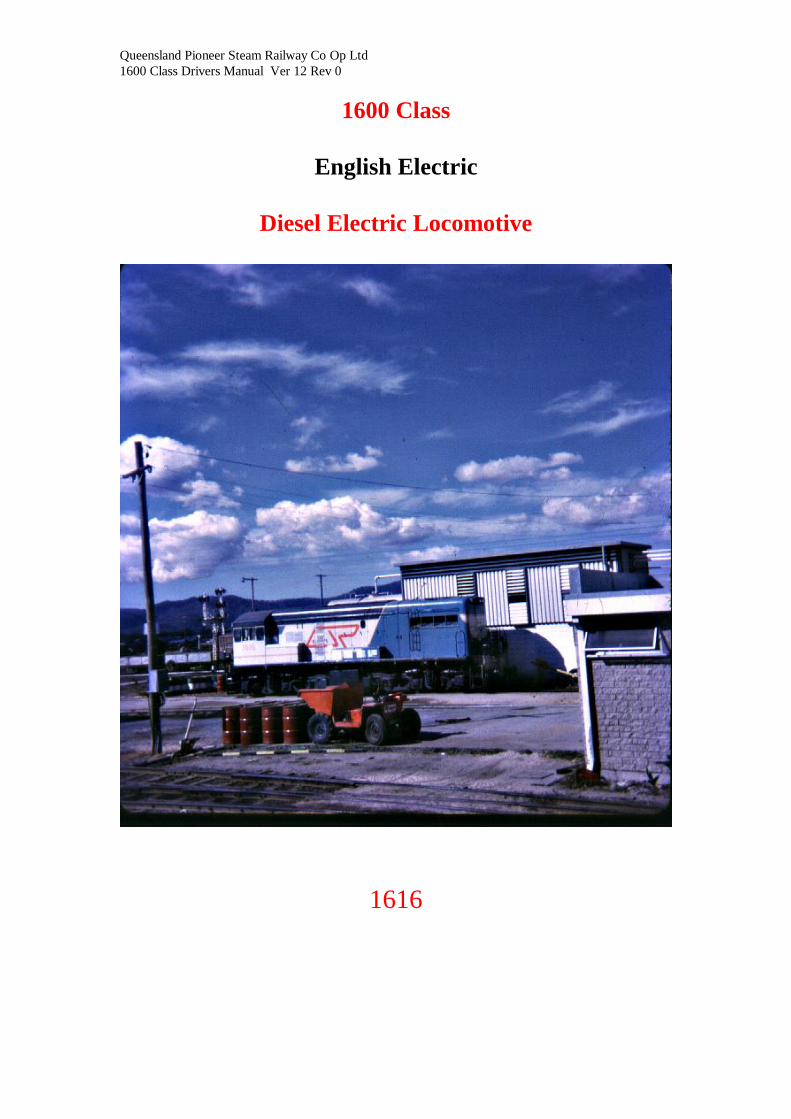
1600 Class
English Electric
Diesel Electric Locomotive
1616
1600 Class
Drivers Instruction Manual
Page 1600 - 2
Table of Contents
INTRODUCTION ............................................................................................ 5
GENERAL DATA ........................................................................................... 5
LAYOUT OF LOCOMOTIVE .......................................................................... 6
LAYOUT OF DRIVING CAB........................................................................... 8
DRIVER'S SWITCH AND INSTRUMENT PANELS ........................................ 8
THE DIESEL ENGINE .................................................................................... 9 DATA ............................................................................................................................................ 10
ENGINE FUEL SYSTEM .............................................................................. 11
ENGINE LUBRICATING OIL SYSTEM ........................................................ 12
ENGINE COOLING WATER SYSTEM ......................................................... 13
ELECTRICAL MACHINES ........................................................................... 19 MAIN GENERATOR ................................................................................................................... 19
AUXILIARY GENERATOR ....................................................................................................... 19
TRACTION MOTORS ................................................................................................................ 19
FUEL SUPPLY PUMP MOTOR ................................................................................................. 19
CONTROL GEAR ........................................................................................................................ 20
CONTROL FRAME (CAB SIDE) ............................................................................................... 22
LAYOUT OF CONTROL FRAME (Rear View) ........................................................................ 23
OPERATING INSTRUCTIONS ..................................................................... 25
PREPARATION FOR STARTING ................................................................ 25 Preparation after a 24 hour lie-over period if locomotive not prepared for traffic by fitters .... 25
Preparation after a short lie-over period ..................................................................................... 25
STARTING THE ENGINE .......................................................................................................... 26
DRIVING ...................................................................................................... 26 Starting characteristics. ................................................................................................................ 26
To Move Off:- ............................................................................................................................... 27
To Stop:- ....................................................................................................................................... 27
To Reverse:- .................................................................................................................................. 27
NOTES ON DRIVING ................................................................................... 27 Driving ammeter. .......................................................................................................................... 27
Coasting......................................................................................................................................... 27
Accelerating................................................................................................................................... 27
Operation over points and crossings. ........................................................................................... 28
Changing Driving Positions. ......................................................................................................... 28
STABLING THE LOCOMOTIVE .............................................................................................. 28
MISCELLANEOUS OPERATING INSTRUCTIONS ..................................... 29 WHEELSLIP. ............................................................................................................................... 29
RUNNING THROUGH WATER ................................................................................................ 29
High Water Temperature. ............................................................................................................ 30
Earth Fault .................................................................................................................................... 30
Low Oil Pressure. .......................................................................................................................... 30
Fire Warning. ................................................................................................................................ 31
Water level. ................................................................................................................................... 31
Battery charge. .............................................................................................................................. 31
Traction motor failure .................................................................................................................. 31
TOWING THE LOCOMOTIVE ................................................................................................. 32
INSTRUCTIONS TO SHED STAFF FOR PRIMING THE FUEL SYSTEM ... 33 Hotplate. ........................................................................................................................................ 34
Pneuphonic Horn. ......................................................................................................................... 34
Shed supply sockets. ..................................................................................................................... 34
1600 Class
Drivers Instruction Manual
Page 1600 - 3
MULTIPLE OPERATION ............................................................................. 35 Coupling and Uncoupling Units. .................................................................................................. 35
Coupling. ....................................................................................................................................... 35
Uncoupling. ................................................................................................................................... 35
Preparation for starting multiple units. ....................................................................................... 35
Starting tbe engine. ....................................................................................................................... 35
Preparation for driving. ................................................................................................................ 35
Driving........................................................................................................................................... 36
Changing driving cabs .................................................................................................................. 36
SAFETY PRECAUTIONS ............................................................................. 37 To kill High Voltage ...................................................................................................................... 37
TO KILL LOW VOLTAGE : .......................................................................... 37 To prevent the engine starting accidentally: ............................................................................... 37
FIRE PRECAUTIONS AND FIRE FIGHTING. .............................................. 38 Fire Precautions. ........................................................................................................................... 38
Fire fighting................................................................................................................................... 38
FAULT LOCATION ...................................................................................... 39
FOR THE INFORMATION OF THE MAINTENANCE STAFF....................... 39 Multiple unit operation................................................................................................................. 39

1600 Class
Drivers Instruction Manual
Page 1600 - 4
1600 Class
Drivers Instruction Manual
Page 1600 - 5
INTRODUCTION
The locomotive is termed a ""diesel-electric"‘ locomotive because its prime mover is a diesel engine,
power from which is transmitted to the locomotive driving wheels by electrical means. Throughout this
book, the word "engine" refers only to the diesel engine. The words "unit" or "locomotive" refer to the
vehicle as a whole. ln the case of two or more units being coupled together, the term "multiple unit
locomotive" will be used.
GENERAL DATA
Class of locomotive ......................................................................... 1600
Type of locomotive .......................................................................... Diesel-electric
Rating of locomotive ....................................................................... 925 h.p.
Maximum permissible track speed ................................................. 50 m.p.h.
Weight of locomotive in running order .......................................... 61.5 tons
Weight of bogie in running order .................................................. 13.6 tons
Weight per axle ............................................................................ 10.25 tons
Gauge ............................................................................................ 3'-6"
Wheel arrangement ........................................................................ Co-Co
Number of driving wheels.................................................................. 12
Diameter of driving wheels-new ....................................................... 3'-1 1/2"
minimum permissible........................................................................ 2'-9 3/8"
Axle bearings (make and type) ......................................................... S.K.F. 23124C/C3
Wheelbase of locomotive .................................................................. 32'-0"
Wheelbase of bogie .......................................................................... 1 1 '-6"
Distance between bogie centers ........................................................ 25'-6"
Length over buffers .......................................................................... 44'-2"
Maximum width .............................................................................. 9'-01/2"
Maximum height ............................................................................. 12'-81/2"
Minimum curve negotiable............................................................... 250'-0"
Clearance to rail level (new wheels) ................................................. 5 1/4"
Clearance to rail level (max. permissible wheel wear) ...................... 3-3716"
Brake equipment .................................................................... .......... Westinghouse Air
Compressor (make and type) ............................................................. W.H.B. 3CDC
Air pressure - maximum .............................................................. 110 lbs./sq"
minimum................................................................ 95 lbs/sq"
Relief valve setting ........................................................................... 120 "
Speedometer (make and type)............................................................ HASLER TEL AI 537
Fuel tank capacity .............................................................................. 600 gallons
Sandbox capacity ............................................................................... 13 cub. ft.
Cooling water capacity........................................................................ 100 gallons
Lubricating oil capacity ...................................................................... 60 gallons
1600 Class
Drivers Instruction Manual
Page 1600 - 6
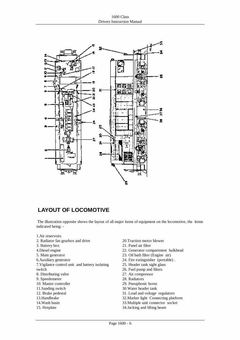
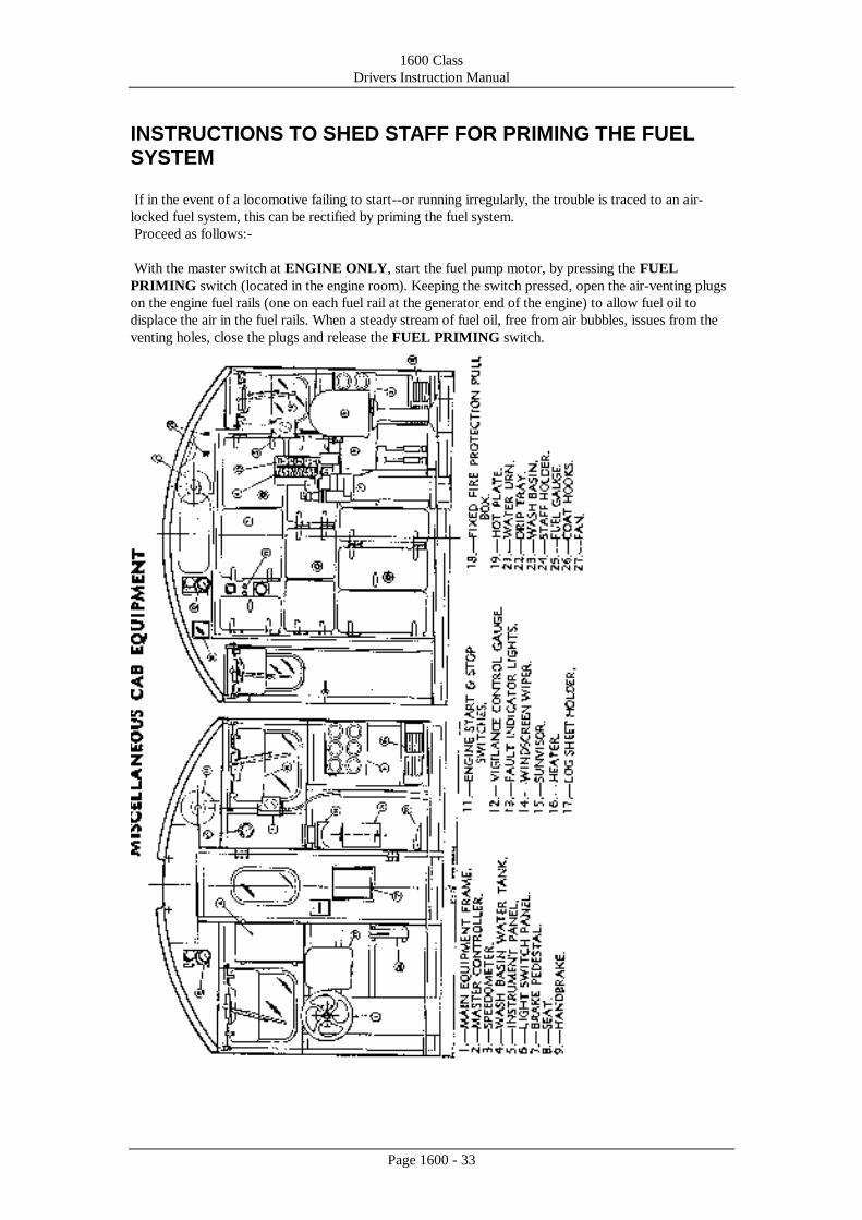
LAYOUT OF LOCOMOTIVE
The illustration opposite shows the layout of all major items of equipment on the locomotive, the items
indicated being: -
1.Air reservoirs
2. Radiator fan gearbox and drive
3. Battery box
4.Diesel engine
5. Main generator
6.Auxiliary generator
7.Vigilance control unit and battery isolating
switch
8. Distributing valve
9. Speedometer
10. Master controller
11.Sanding switch
12. Brake pedestal
13.Handbrake
14.Wash basin
15. Hotplate
20.Traction motor blower
21. Panel air filter
22. Generator compartment bulkhead
23. Oil bath filter (Engine air)
24. Fire extinguisher (portable) .
25. Header tank sight glass
26. Fuel pump and filters
27. Air compressor
28. Radiators
29. Pneuphonic horns
30.Water header tank
31. Load and voltage regulators
32.Marker light Connecting platform
33.Multiple unit connector socket
34.Jacking and lifting beam
1600 Class
Drivers Instruction Manual
Page 1600 - 7
16.Water urn
17.Switch and indicator panels
18.Fixed CO2 cylinder
19.Control cubicle
35.Fuel tank
36.Fuel filler
37.Fuel contents gauge
38.Head and numeral lights
1600 Class
Drivers Instruction Manual
Page 1600 - 8
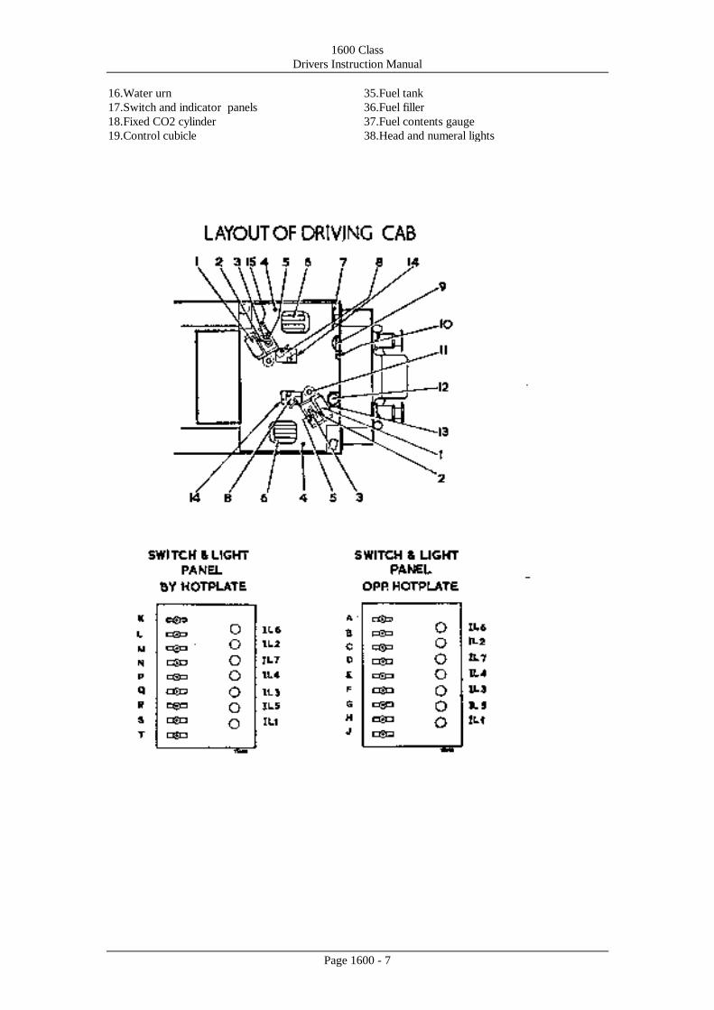
LAYOUT OF DRIVING CAB
The illustration opposite shows the layout of the driving cab, the items indicated being: -
1. Driver's switch and instrument panels (see below)
2. Main power handle
3. Reverse handle
4. Sanding switch
5. Controller key
6. Seat.
7. Handbrake
8. Brake controller
9. Wash basin
10. Fuel contents gauge
11. Fire extinguishers
12. Hotplate
13. Water urn
1 4. Brake valve isolating cock
1 5. Headlight change over switch
DRIVER'S SWITCH AND INSTRUMENT PANELS
INDICATOR LIGHTS .
IL1.-Battery charge G Hand lamps
IL2. -Earth fault H Headlights front
IL3.-Low oil pressure (ON/OFF)
IL4.-Water level J Headlights, front
IL5.-High water ( FULL/DIM)
temperature K Cab Lights ( left hand
IL6.-Wheelslip side)
IL7.-Fire warning L Marker lights ( rear)
SWITCHES M Instrument lights
N Numeral lights
A Cab lights ( right hand P Step lights ,
side) Q Cab heater ( left hand side)
B Front marker lights
C Interior lights R Auto. sanding cut-out
D Control frame lights switch
E Auto. sanding cut-out S Headlight, rear
switch (ON/OFF)
F Cab heater (right hand T Headlight rear
side) (FULL/DIM)
1600 Class
Drivers Instruction Manual
Page 1600 - 9
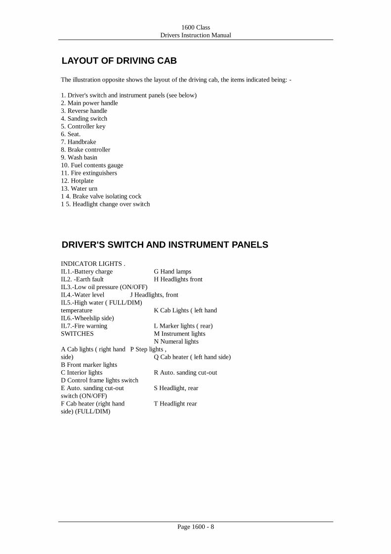
THE DIESEL ENGINE
The power for operating the locomotive is produced by an English Electric diesel engine, type 6CSRKT.
This is a six cylinder engine which is turbo-blown and charge-cooled.
The turbo-blowers are mounted on the engine, above the main and auxiliary generators. Air from the
turbo-blowers is cooled in the charge cooler before being admitted to the engine cylinders.
Turbo-blowing and charge cooling allows the engine to be operated at a higher output than would
otherwise be possible.
Engine speed is controlled pneumatically by means of the main power handle on the master controller,
the speed range of the engine being from 450 to 850 rev./min. If the speed rises above approximately
1,000 rev./min., the mechanically operated overspeed trip operates and shuts down the engine by
returning the fuel pump racks to the "no fuel" position. Indication that the mechanism has tripped is
given by the absence of a chrome button, which, in the untripped position, protrudes from the barrel of
the device.
1600 Class
Drivers Instruction Manual
Page 1600 - 10
DATA
Engine type ---------------------------- 6 CSKRT
Rating --------------------------------- 925 b.h.p. at 850 rev./min.
Firing Order --------------------------- 1, 5, 3, 6, 2, 4
Lubricating oil sump capacity ---------- 60 gallons (approx.)
Lubricating oil pressure --------------- 60Ib./sq. in-
High water temperature warning switch for:--
Jacket water ........... Contacts set to break at 200°F. rising
Charge cooler water .... Contacts set to break at I 40°F. rising
Turbo-blower type NAPlER HP200Z INT.
Governor settings for shut down on low oil pressure :
Shut down at minimum speed -------------- 20Ib./sq.in.
Shut down at full speed ----------------- 35Ib./sq. in.
The fuel, lubricating oil and water systems on the locomotive are briefly described on the following
pages.
1600 Class
Drivers Instruction Manual
Page 1600 - 11
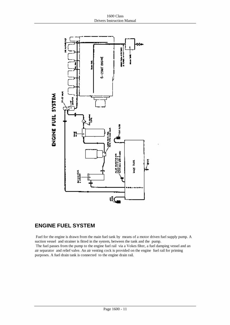
ENGINE FUEL SYSTEM
Fuel for the engine is drawn from the main fuel tank by means of a motor driven fuel supply pump. A
suction vessel and strainer is fitted in the system, between the tank and the pump.
The fuel passes from the pump to the engine fuel rail via a Vokes filter, a fuel damping vessel and an
air separator and relief valve. An air venting cock is provided on the engine fuel rail for priming
purposes. A fuel drain tank is connected to the engine drain rail.
1600 Class
Drivers Instruction Manual
Page 1600 - 12
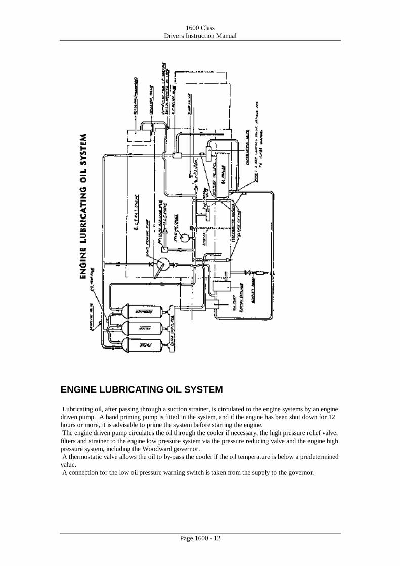
ENGINE LUBRICATING OIL SYSTEM
Lubricating oil, after passing through a suction strainer, is circulated to the engine systems by an engine
driven pump. A hand priming pump is fitted in the system, and if the engine has been shut down for 12
hours or more, it is advisable to prime the system before starting the engine.
The engine driven pump circulates the oil through the cooler if necessary, the high pressure relief valve,
filters and strainer to the engine low pressure system via the pressure reducing valve and the engine high
pressure system, including the Woodward governor.
A thermostatic valve allows the oil to by-pass the cooler if the oil temperature is below a predetermined
value.
A connection for the low oil pressure warning switch is taken from the supply to the governor.
1600 Class
Drivers Instruction Manual
Page 1600 - 13
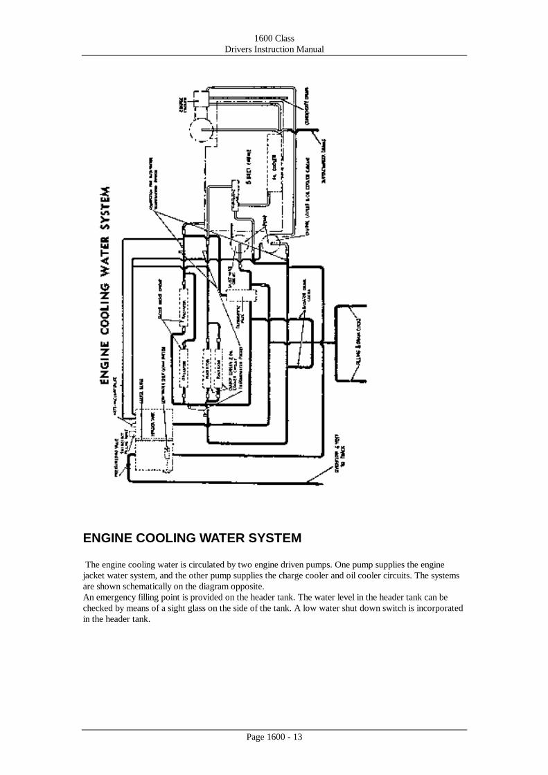
ENGINE COOLING WATER SYSTEM
The engine cooling water is circulated by two engine driven pumps. One pump supplies the engine
jacket water system, and the other pump supplies the charge cooler and oil cooler circuits. The systems
are shown schematically on the diagram opposite.
An emergency filling point is provided on the header tank. The water level in the header tank can be
checked by means of a sight glass on the side of the tank. A low water shut down switch is incorporated
in the header tank.
1600 Class
Drivers Instruction Manual
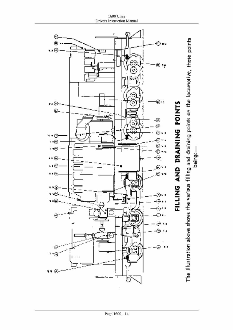
Page 1600 - 14
1600 Class
Drivers Instruction Manual
Page 1600 - 15

1600 Class
Drivers Instruction Manual
Page 1600 - 16
1600 Class
Drivers Instruction Manual
Page 1600 - 17
1600 Class
Drivers Instruction Manual
Page 1600 - 18
1600 Class
Drivers Instruction Manual
Page 1600 - 19
ELECTRICAL MACHINES
MAIN GENERATOR
The main generator, which supplies electrical power to the traction motors, is mounted directly on the
engine, its armature being coupled directly to the engine crankshaft.
A series winding in the generator field system enables the machine to be run as a motor, on current
supplied by the battery, for starting the engine.
AUXILIARY GENERATOR
The auxiliary generator is belt driven from the end of the main generator. The machine supplies current
at 110 volts for the main generator separately excited field, the auxiliary services of the locomotive, and
battery charging.
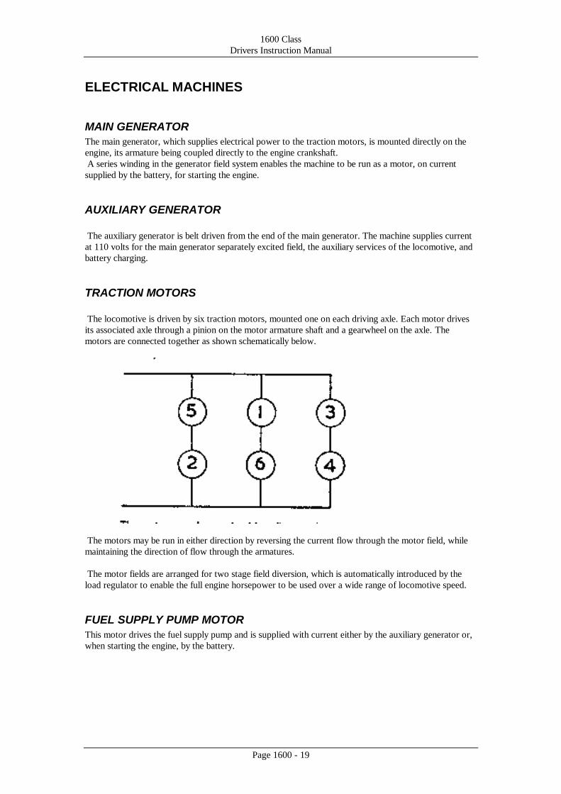
TRACTION MOTORS
The locomotive is driven by six traction motors, mounted one on each driving axle. Each motor drives
its associated axle through a pinion on the motor armature shaft and a gearwheel on the axle. The
motors are connected together as shown schematically below.
The motors may be run in either direction by reversing the current flow through the motor field, while
maintaining the direction of flow through the armatures.
The motor fields are arranged for two stage field diversion, which is automatically introduced by the
load regulator to enable the full engine horsepower to be used over a wide range of locomotive speed.
FUEL SUPPLY PUMP MOTOR
This motor drives the fuel supply pump and is supplied with current either by the auxiliary generator or,
when starting the engine, by the battery.
1600 Class
Drivers Instruction Manual
Page 1600 - 20
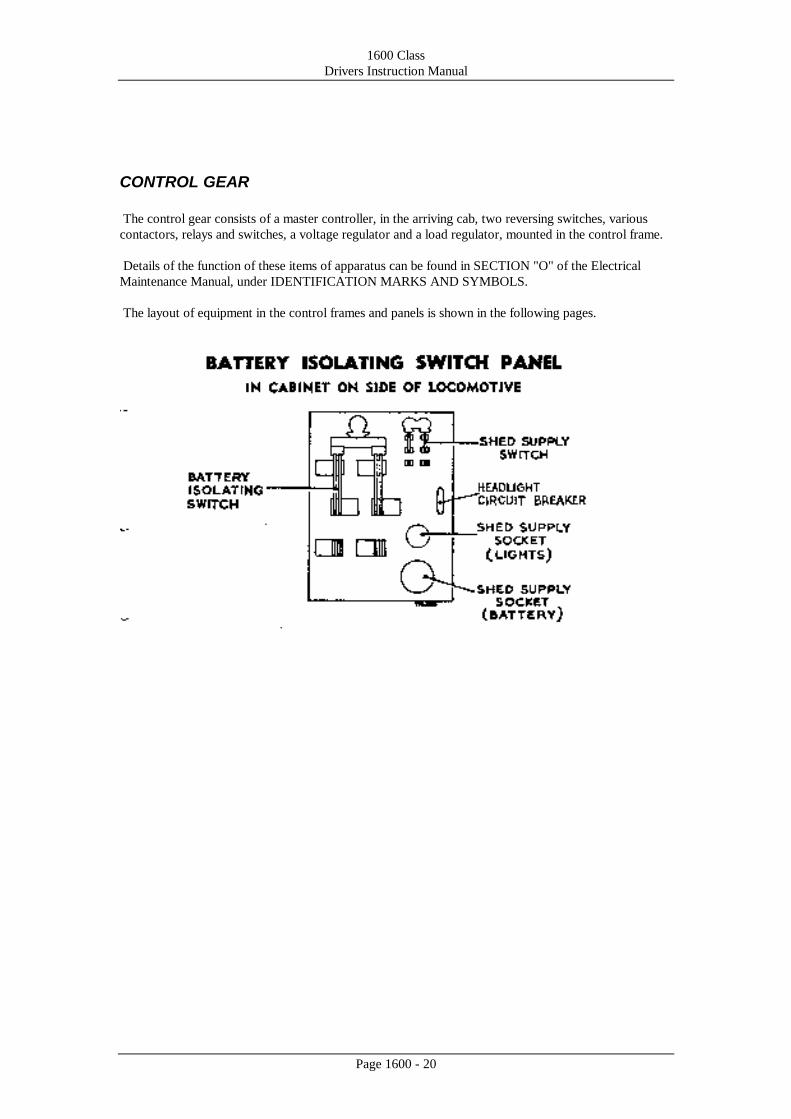
CONTROL GEAR
The control gear consists of a master controller, in the arriving cab, two reversing switches, various
contactors, relays and switches, a voltage regulator and a load regulator, mounted in the control frame.
Details of the function of these items of apparatus can be found in SECTION "O" of the Electrical
Maintenance Manual, under IDENTIFICATION MARKS AND SYMBOLS.
The layout of equipment in the control frames and panels is shown in the following pages.
1600 Class
Drivers Instruction Manual
Page 1600 - 21
1600 Class
Drivers Instruction Manual
Page 1600 - 22
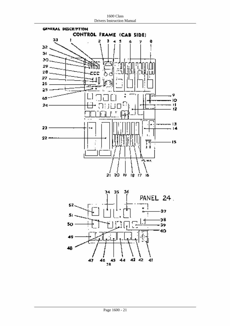
CONTROL FRAME (CAB SIDE)
1. Control circuit breaker
2. Engine start button
3. Battery voltmeter
4. Engine stop button
5. Field divert contactor FDIA
6. Field divert contactor FDIB
7. Field divert contactor FDZA
8. Field divert contactor FDZB
9. Battery charging BCC contactor
10. Generator field contactor GFC
11. Generator starting contactor Sl
12. Generator starting contactor SZ
13. Auxiliary generator field contactor AFC
14. Start control contactor SCG
15. Auxiliary generator isolating switch AGS
16. Motor contactor M5
17. Motor contactor M3
18. Motor contactor Ml
19. Motor contactor M6
20. Motor contactor M4
21. Motor contactor M2
22. Reverser K
23. Reverser L
24. Relay panel
25. Control air pressure gauge
26. Auxiliary control circuit breaker
27. Isolating switch ( Batt. discharge
alarm)
28. Earth switch
29. Motor cut-out links
30. Boiling ring circuit breaker
31. Cab heater circuit breaker
32. Sanding circuit breaker
33. Main lighting circuit breaker
34. Wheelslip relay WS3
35. Wheelslip relay WSl
36. Wheelslip relay WSZ
37. H.T. Test terminals
38. Wheelslip relay WS4
39. Fire alarm relay FAR
40. Wheelslip slave relay SWRl
41. Control cut-out switch COS
42. Low water relay WLR
43. Oil pressure indicating relay OPR
44. Engine stop relay ESR
45. Water temperature relay WTR
46. Indicator light relay ILR
47. Auxiliary relay AR
48. Wheelslip slave relay SWR2
49. Earth fault relay EFR
50. Current limit relay CLR2
51. Wheelslip slave relay SWR3
52. Current limit relay CLRl
53. Fuse test terminals
1600 Class
Drivers Instruction Manual
Page 1600 - 23
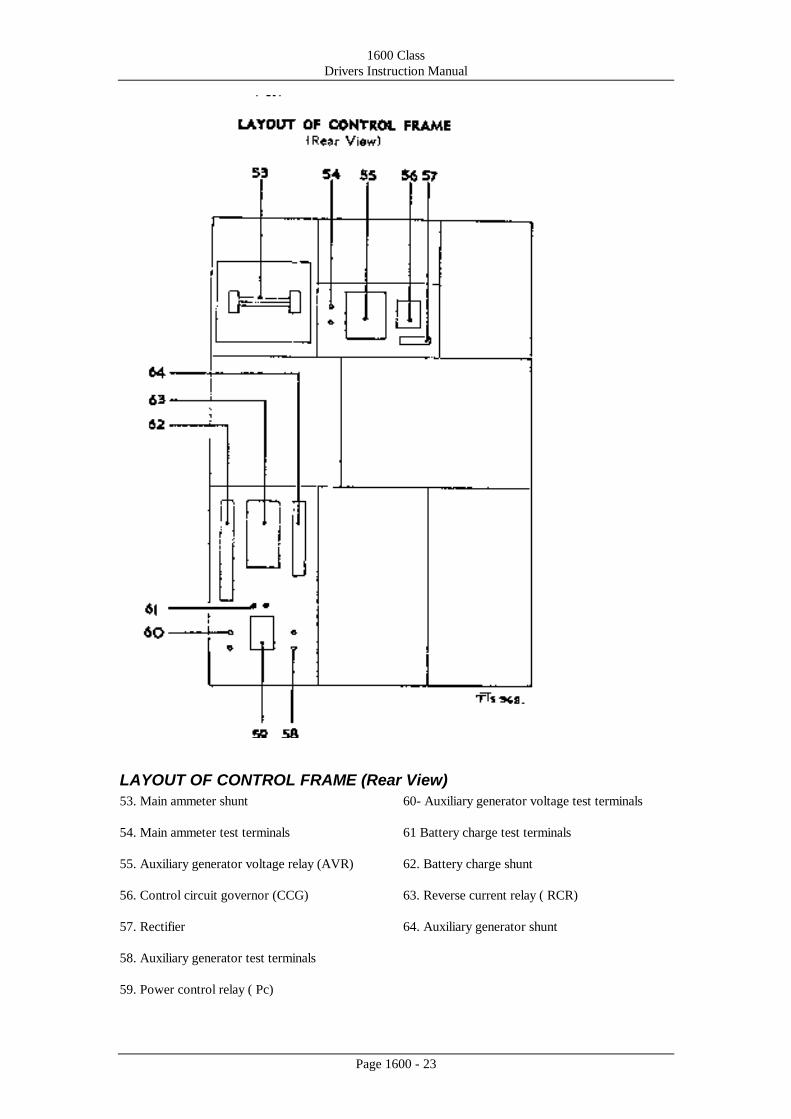
LAYOUT OF CONTROL FRAME (Rear View)
53. Main ammeter shunt
54. Main ammeter test terminals
55. Auxiliary generator voltage relay (AVR)
56. Control circuit governor (CCG)
57. Rectifier
58. Auxiliary generator test terminals
59. Power control relay ( Pc)
60- Auxiliary generator voltage test terminals
61 Battery charge test terminals
62. Battery charge shunt
63. Reverse current relay ( RCR)
64. Auxiliary generator shunt

1600 Class
Drivers Instruction Manual
Page 1600 - 24
1600 Class
Drivers Instruction Manual
Page 1600 - 25
OPERATING INSTRUCTIONS
PREPARATION FOR STARTING
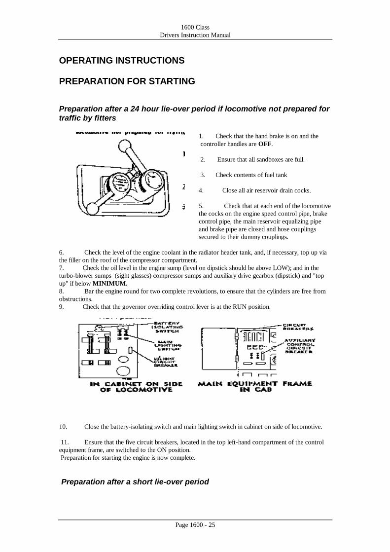
Preparation after a 24 hour lie-over period if locomotive not prepared for traffic by fitters
1. Check that the hand brake is on and the
controller handles are OFF.
2. Ensure that all sandboxes are full.
3. Check contents of fuel tank
4. Close all air reservoir drain cocks.
5. Check that at each end of the locomotive
the cocks on the engine speed control pipe, brake
control pipe, the main reservoir equalizing pipe
and brake pipe are closed and hose couplings
secured to their dummy couplings.
6. Check the level of the engine coolant in the radiator header tank, and, if necessary, top up via
the filler on the roof of the compressor compartment.
7. Check the oil level in the engine sump (level on dipstick should be above LOW); and in the
turbo-blower sumps (sight glasses) compressor sumps and auxiliary drive gearbox (dipstick) and "top
up" if below MINIMUM.
8. Bar the engine round for two complete revolutions, to ensure that the cylinders are free from
obstructions.
9. Check that the governor overriding control lever is at the RUN position.
10. Close the battery-isolating switch and main lighting switch in cabinet on side of locomotive.
11. Ensure that the five circuit breakers, located in the top left-hand compartment of the control
equipment frame, are switched to the ON position.
Preparation for starting the engine is now complete.
Preparation after a short lie-over period
1600 Class
Drivers Instruction Manual
Page 1600 - 26
If the engine has stopped for only a short time, preparation may be limited to a check that the hand
brake is on and that there is sufficient fuel oil for the job in hand.
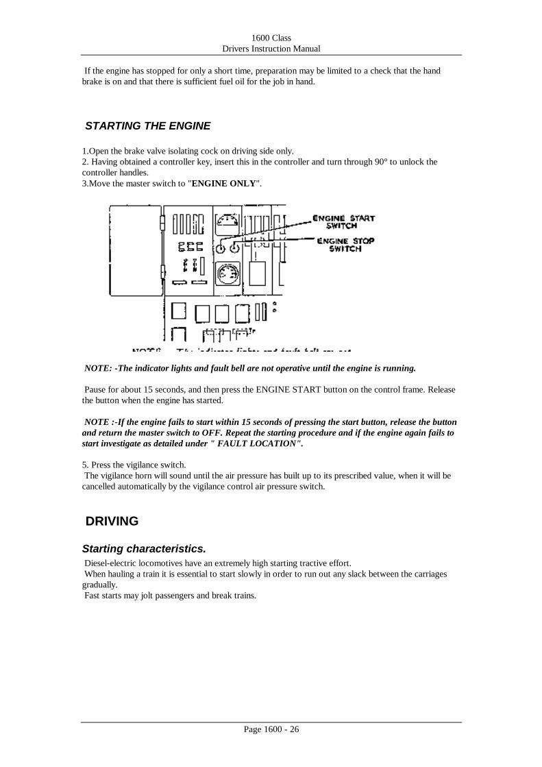
STARTING THE ENGINE
1.Open the brake valve isolating cock on driving side only.
2. Having obtained a controller key, insert this in the controller and turn through 90° to unlock the
controller handles.
3.Move the master switch to "ENGINE ONLY".
NOTE: -The indicator lights and fault bell are not operative until the engine is running.
Pause for about 15 seconds, and then press the ENGINE START button on the control frame. Release
the button when the engine has started.
NOTE :-If the engine fails to start within 15 seconds of pressing the start button, release the button
and return the master switch to OFF. Repeat the starting procedure and if the engine again fails to
start investigate as detailed under " FAULT LOCATION".
5. Press the vigilance switch.
The vigilance horn will sound until the air pressure has built up to its prescribed value, when it will be
cancelled automatically by the vigilance control air pressure switch.
DRIVING
Starting characteristics.
Diesel-electric locomotives have an extremely high starting tractive effort.
When hauling a train it is essential to start slowly in order to run out any slack between the carriages
gradually.
Fast starts may jolt passengers and break trains.
1600 Class
Drivers Instruction Manual
Page 1600 - 27
To Move Off:-
1. Release the hand brake.
NOTE :-An audible warning sounds every 11/2 to 2 minutes and must be cancelled by pressing the
vigilance switch. FAILURE TO ACKNOWLEDGE WILL RESULT IN A PENALTY BRAKE
APPLICA TION ( This will take place 20 to 30 seconds after the audible warning.)
2. Move the master switch to FORWARD or REVERSE.
3. Partly release the air brake in use and advance the control handle until the driving ammeter shows
current then release the brakes fully and advance the control handle until the locomotive begins to
move. Continue to advance the control handle, slowly, until the required speed is obtained.
NOTE.-If the locomotive starts to run back when the brakes are released, re-apply the brakes and
return the control handle to OFF before making a second attempt to move off. ON NO ACCOUNT
MUST POWER BE APPLIED TO THE LOCOMOTIVE WHILE IT IS MOVING IN THE
OPPOSITE DIRECTION TO THAT FOR WHICH THE MASTER SWITCH IS SET.
To Stop:-
1. Return the control handle to OFF.
2- Apply the brakes.
3. If the stop is to be of short duration, apply the locomotive air brake and release the train brakes in
preparation for moving off.
4. If standing, move the master switch to EO and apply the hand brake.
To Reverse:-
I . Return the control handle to OFF.
2. Apply the brakes.
3. WHEN THE LOCOMOTIVE HAS STOPPED, move master switch to the appropriate position.
4. Proceed to move in the normal manner.
IMPORTANT. NEVER MOVE THE MASTER SWITCH WHEN THE LOCOMOTIVE IS IN
MOTION.
NOTES ON DRIVING
Driving ammeter.
The following ammeter readings must not be exceeded :-
A maximum current of 1,550 amps may be used to start a train.
In any one hour EITHER - currents of 14OO to 1,550 amps may be used for periods not exceeding a
total of 5 minutes.
OR - currents of 1,200 to 1,400 amps may be used for periods not exceeding a total of 30 minutes.
Driving currents below 1,200 amps may be used continuously.
Coasting.
Where conditions permit the control handle may be returned to the OFF position and the locomotive
allowed to coast, but the MAXIMUM SPEED OF 50 M.P.H. MUST NOT BE
EXCEEDED.
Accelerating.
Care should be taken not to advance the control handle too quickly at low speed or wheelslip may
result.
When accelerating from speeds in excess of 10 m.p.h, the control handle may be advanced more quickly
than when accelerating from rest.
1600 Class
Drivers Instruction Manual
Page 1600 - 28
Operation over points and crossings.
When operating over points and crossings, it is advisable to reduce power before reaching the crossing,
and not to increase power again until all locomotive units have passed over
Changing Driving Positions.
Remove the brake valve handles and close the isolating cock on the pedestal. Open the isolating cock
on the pedestal to be used and fit the brake valve handles. The locomotive is now ready for operation in
the other direction.
STABLING THE LOCOMOTIVE
1.Place locomotive on SKATE
2. Stop the engine.
3. Open battery-isolating switch.
4.Switch off main lighting switch in cabinet on side of locomotive.
5.Apply the handbrake if operative
6.Remove key and place in safe area
1600 Class
Drivers Instruction Manual
Page 1600 - 29
MISCELLANEOUS OPERATING INSTRUCTIONS
WHEELSLIP.
When starting heavy trains or if the control is advanced too rapidly, wheelslip may occur.
This will be indicated by the wheelslip indicator light shining brightly and the sounding of the horn.
Power will be reduced and sand automatically applied to the rails if sanding isolating switches are
closed. Sanding can be carried out manually from each driving position.
With excessive wheelslip, electrical power may be automatically shut off and can only be restored by
returning the control handle to off and re-applying power.
Simultaneous wheelslip of all axles will not be detected by the wheelslip relays, but can be observed by
a sudden rise in speed on the speedometer needle. If this should occur, reduce power by notching" back
and apply sand to the rails before notching up again.
RUNNING THROUGH WATER
These locomotives are not permitted to travel through flooded areas unless top of rail is visible, with
the exception that in low-lying country with poor run off, the locomotives may proceed through such
water of a depth not exceeding three inches above rail level at a maximum speed of 3 m.p.h.
Permission must be obtained from Locomotive and Carriage Supervisor
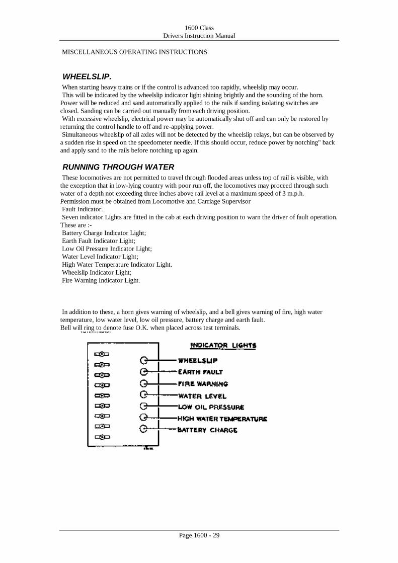
Fault Indicator.
Seven indicator Lights are fitted in the cab at each driving position to warn the driver of fault operation.
These are :-
Battery Charge Indicator Light;
Earth Fault Indicator Light;
Low Oil Pressure Indicator Light;
Water Level Indicator Light;
High Water Temperature Indicator Light.
Wheelslip Indicator Light;
Fire Warning Indicator Light.
In addition to these, a horn gives warning of wheelslip, and a bell gives warning of fire, high water
temperature, low water level, low oil pressure, battery charge and earth fault.
Bell will ring to denote fuse O.K. when placed across test terminals.

1600 Class
Drivers Instruction Manual
Page 1600 - 30
High Water Temperature.
If the temperature of the engine cooling water reaches 200°F., the water temperature switch will close
and the driver is warned of the fault by the fault bell ringing and by the brilliance of the water
temperature indicator light.
1. Stop the locomotive and move the master switch to ENGINE ONLY. Do not stop the engine.
2. Check that water is showing in the header tank sight glass and top up if necessary. Do not add cold
water. If no water visible in sight glass.
3. Check the cooling system for leakage.
4. Check that radiator fan is running; if not, shut down the engine and request assistance-
5. If fan is running put master switch to ENGINE ONLY and run the engine until water temperature
drops and water temperature relay resets.
6. Resume normal operation. If trouble persists, request assistance.
Earth Fault
Should an earth fault develop in the power circuits, the fault bell will ring continuously and the earth
fault indicator light shine brightly. Power will automatically be cut off from the traction motor circuits
and the engine speed returned to idling.
Proceed as follows: -
1. To stop the bell - bring the locomotive to a standstill, then move the master switch to OFF
2. Return master switch to FOR or REV. depending on direction of travel.
3. Throttle up to see if fault persists.
4. If fault persists, set master switch to ENGINE ONLY and check for presence of smoke from the
traction motors.
Cut out each pair of motors in turn, each time applying power to see if fault persists. If loco will
operate on 4 motors, proceed. If not, request assistance.
5. Clear the section and report the fault to the Locomotive and Carriage Supervisor
Low Oil Pressure.
If the lubricating oil pressure falls below 25 pounds per square inch, the driver is warned of the fault by
the ringing of the fault bell and by the brilliance of the oil pressure indicator light.
Proceed as follows with engine at idle speed.
Check the lubricating oil pressure gauge reading-
(a) If the pressure is above 45 p.s.i. clear the main line, check oil level in the engine sump and top up if
necessary.
(b) If the pressure is below 45 p.s.i. the locomotive is a failure and must be withdrawn from service
Immediately.
1600 Class
Drivers Instruction Manual
Page 1600 - 31
Fire Warning.
Should a fire occur in the engine room, the driver is warned by the fault bell ringing and by the brilliance
of the Fire Warning indicator light.
Proceed as follows: -
1. Stop the locomotive.
2. Shut down the engine.
3. Break the glass on the fire extinguisher pull box located in the cab above the main cubicle and pull
the handle.
This operates the fire extinguisher system in the engine compartment.
Water level.
If the fault bell rings and the water level indicator light shines brightly, the level of the engine cooling
water has dropped to the minimum safety level.
Proceed as follows:-
1 - Stop the locomotive. Do not shut down the engine.
2. Check the water system for leakage.
(a) If a major leak is present, the locomotive is a failure.
Shut down the engine.
(b) If little or no leakage is present, check the level of the water on the gauge glass of the water header
tank and top up if necessary through the emergency filler on the roof of the locomotive.
Do not add cold water if no water visible in sight glass.
Battery charge.
If the auxiliary generator is not charging the battery, the fault bell will ring and the battery charge
indicator light will shine brightly. In addition to these the battery ammeter on the instrument panel will
fail to register a charge.
Proceed as follows: -To stops the bell open alarm-isolating switch (Ref.27, page 26)
Withdraw the locomotive from service as soon as possible, but, meanwhile, AVOID STOPPING THE
ENGINE-
Traction motor failure
In the following case, no indication will be given by the fault indicator, but it may be given by wheelslip
indication when there is no wheelslip or abnormal operation of the overload relays.
The procedure in the event of a traction motor failure should be as follows:-
1. Stop the locomotive and apply the hand brake.
2. Return the master switch to ENGINE ONLY.
3. Inspect the traction motors for any obvious indication as to which motor is faulty (e.g., overheating,
presence of smoke, etc.).
4. Isolate the faulty motor by opening the appropriate motor cutout link on the L.T. switch and fuse
panel shown on page 40.
If it is not obvious which motor is defective, pairs of motors should be isolated in turn and reconnected
if the fault persists.
NOTE: -The motors are isolated in pairs, i.e., one link isolates motors 1 and 6, a second link
isolates motors 2 and 5, and the third link isolates motors 3 and 4.
With a pair of motors isolated, the locomotive may be operated on reduced current, not exceeding two-
thirds of normal driving currents. See page 37.

1600 Class
Drivers Instruction Manual
Page 1600 - 32
TOWING THE LOCOMOTIVE
Should it become necessary to tow a "dead" diesel-electric locomotive, the "dead" locomotive must
first be prepared as follows: -
1. Ensure that the controller handles are in the OFF position and remove the controller key.
2. Move the air brake handle to their running positions.
3. Open the battery-isolating switch.
4. Set the reversing switches in the control cubicle to neutral (central) position. (All contacts open).
5. Couple air brake pipes in the normal way.
6. Release the hand brake before moving off.
7. Open dead engine cock.
8. Close both brake valve isolating cocks.
1600 Class
Drivers Instruction Manual
Page 1600 - 33
INSTRUCTIONS TO SHED STAFF FOR PRIMING THE FUEL
SYSTEM
If in the event of a locomotive failing to start--or running irregularly, the trouble is traced to an air-
locked fuel system, this can be rectified by priming the fuel system.
Proceed as follows:-
With the master switch at ENGINE ONLY, start the fuel pump motor, by pressing the FUEL
PRIMING switch (located in the engine room). Keeping the switch pressed, open the air-venting plugs
on the engine fuel rails (one on each fuel rail at the generator end of the engine) to allow fuel oil to
displace the air in the fuel rails. When a steady stream of fuel oil, free from air bubbles, issues from the
venting holes, close the plugs and release the FUEL PRIMING switch.

1600 Class
Drivers Instruction Manual
Page 1600 - 34
Hotplate.
An electric hotplate is provided in the driving cab. It can only be operated when the engine is running.
Pneuphonic Horn.
These horns are operated from the driving cab.
Shed supply sockets.
When the locomotive is in the shed, it is possible for the battery to be charged, and the lights operated,
from the shed supply.
To meet these requirements, sockets (and, for the lights, a change-over switch) are provided; these are
located on the battery isolating switch panel.
To charge the battery - connect a 110 volt d.c. external supply to the external charging sockets on the
locomotive.
If lights are required - connect a 110-volt external supply to the shed supply socket on the locomotive,
then turn the lighting changeover switch to the "SHED SUPPLY” position.
1600 Class
Drivers Instruction Manual
Page 1600 - 35
MULTIPLE OPERATION
Coupling and Uncoupling Units.
AII making and breaking of coupler plugs and sockets when coupling or uncoupling units must be
carried out with all engines shut down and control and master switch handles in the OFF position. The
procedure is as follows: -
Coupling.
1. Apply the independent brake on one loco. Bring the locomotives together so that the mechanical
couplings are made and then apply the independent brake on the other unit.
Return all controller handles to the OFF position and stop the diesel engines.
On the second locomotive, close both brake valve isolating cocks and remove both brake handles.
Make all the air connections between the units and open the cocks on the interloco air pipes.
Insert the electrical jumpers in their sockets on the headstocks, ensuring that they are correctly locked.
Uncoupling.
1. Bring the locomotives to a standstill and apply the independent brake in each cab.
2. Return the controller handle to the OFF position and stop both engines.
3. Uncouple the electrical jumpers and return them to their housings.
4. Close the air cocks in the inter locomotive coupling hoses, uncouple the air hoses, and connect them
to their respective dummy couplings.
5. Release the mechanical couplings.
6. Open the brake valve Isolating cock and replace the brake valve handles on the brake valves, leaving
the independent handle in the "Application" position.
Preparation for starting multiple units.
1. Check that at each end of the multiple unit locomotives the coupling cocks are closed. Check that
between locomotives all air couplings are correctly made and the coupling cocks open on each unit.
2- Check that the mechanical couplings and electrical jumpers are correctly connected.
3. In the cab of the controlling locomotive check that the hand brake is on, release the hand brake in the
cab not to be used for driving.
4- Remove the controller key from the controller on the second locomotive.
5. Check that the brake valve isolating cocks on the second locomotive are closed and both brake valve
handles are removed.
Proceed as instructed under "PREPARATION FOR STARTING", Page 34 for each locomotive.
Starting the engine.
The engines on all units are started from the cab of the locomotive to be used for driving.
Proceed as instructed under "STARTING THE ENGINE", Page 35.
Preparation for driving.
Proceed as detailed under "DRIVING", Page 36, for
Single unit locomotive.

1600 Class
Drivers Instruction Manual
Page 1600 - 36
Driving.
1. Treat as single unit.
2. Wheelslip on either locomotive will be indicated in the driving cab. If wheelslip occurs, proceed as if
driving under single unit operation.
3. An earth fault, low oil pressure or high water temperature on the locomotive being used for driving
will be indicated as in single unit operation. These faults, if on the second unit, will be indicated by the
fault bell only ringing in the driving cab. The nature of the fault should be checked
by stopping the train and checking the indicator lights on the second locomotive.
4. When operating in multiple unit, the ammeter current readings should not exceed those specified for
single unit working.
Changing driving cabs
1. Return the control handle to the OFF position and brake the locomotives to a standstill, leaving the
independent brake handle in the "Application" position.
2. Move the master switch handle to the OFF position and remove the controller key.
3. Close the brake valve isolating cock and remove both brake valve handles.
4. Switch off all lights, hotplates, etc., and close the windows, checking that air pressure is registering
on the brake cylinder gauge.
5. Proceed to the other cab.
NOTE:-As the engines will continue running, the change from one cab to the other should be made as
quickly as possible.
6. In the cab of the locomotive, which is now the controlling locomotive, open the brake valve isolating
cock and replace both brake valve handles.
7.Check that the brakes on the second locomotive are released by the brake valve on the controlling
locomotive.
8.Insert the controller key in the controller and proceed as. detailed under "DRIVING", Page 36.
1600 Class
Drivers Instruction Manual
Page 1600 - 37
SAFETY PRECAUTIONS
To kill High Voltage
To kill high voltage - move the master switch ENGINE ONLY.
To kill low voltage: I - Stop the engine.
2. Open the battery isolating switch.
To prevent the engine starting accidentally:
In order to work in safety without danger of someone starting the engine accidentally.
1 . Turn the controller key.
2. Place a "DO NOT START" notice over the controller handles.
To prevent movement of locomotive while engine is, running:
Before leaving the locomotive untended: -
1. Move the master switch to ENGINE ONLY.
2. Apply the independent air brake and hand brake.

1600 Class
Drivers Instruction Manual
Page 1600 - 38
FIRE PRECAUTIONS AND FIRE FIGHTING.
Fire Precautions.
To minimize the risk of fire, the following precautions should be taken: -
1. All personnel concerned with operating the locomotive should be made familiar with the operation of
all fire fighting equipment on the locomotive.
2. Limit smoking to the driver's cabin.
3. Do not leave cleaning rags in the engine room.
4. Do not permit the use of naked lights for inspection purposes in or around the engine room.
5. Do not allow dirt to accumulate on the underframe or bogies.
Fire fighting.
An audible fire warning system forms part of the locomotive equipment.
The system is arranged to operate a fire alarm bell in the cab in the event of a fire occurring in the
engine room. To test the operation of the warning system a test button is provided, and this must be
operated by each driver on taking charge of the locomotive.
NOTE: -The audible fire system only WARNS of a pending fire, and DOES NOT operate the
extinguishers.
Should a fire occur on the locomotive whilst in motion-
1. STOP THE TRAIN.
2. STOP THE ENGINE.
3. BREAK THE GLASS ON THE FIRE EXTINGUISHER, PULL BOX LOCATED IN THE CAB
ABOVE THE MAIN CUBICLE AND PULL THE HANDLE.
In the event of the main or hand extinguishers being operated by accident or in the case of fire, the
matter MUST be reported as soon as possible.
Precautions against crankcase explosions.
NOTE :-As the following precautions are most important, a copy of them is displayed on the crankcase
doors on the engine.
The crankcase gases are vented to atmosphere by a breather, but the gases in the crankcase are too rich
to support combustion.
If the gases are diluted with air they become highly inflammable. If, therefore, it is ever necessary to
remove a crankcase door soon after the engine has stopped, the procedure should be as follows: -
1. Allow 15 to 20 minutes to elapse after stopping the diesel engine, before attempting to release a
crankcase door.
2. Keep all naked lights away from the engine, both during and after removal of the doors.
3. Immediately the doors are removed, dispel the crankcase gases, using a portable, non-electric blower.

1600 Class
Drivers Instruction Manual
Page 1600 - 39
FAULT LOCATION CONTENTS
FAULT 1 ENGINE DOES NOT TURN WHEN START BUTTON IS PRESSED
FAULT 2 ENGINE MOTORS BUT DOES NOT FIRE
FAULT 3 ENGINE STARTS BUT FAILS TO KEEP RUNNING
FAULT 4 BATTERY NOT CHARGING
FAULT 5 AIR PRESSURE FAILS TO BUILD UP
FAULT 6 NO POWER WHEN CONTROL HANDLE IS ADVANCED FROM THE "OFF"
POSITION
FAULT 7 REPEATED LOSS OF POWER WHEN ATTEMPTING TO START THE TRAIN
FAULT 8 COMPLETE LOSS OF POWER
FAULT 9 HIGH WATER TEMPERATURE
FAULT 10 LOW WATER LEVEL
FAULT 11 LOW OIL PRESSURE
FAULT 12 ENGINE STOPS
FOR THE INFORMATION OF THE MAINTENANCE STAFF
Should faulty operation occur, the actions indicated in the following suggestions for fault finding should
be carried out in sequence A, B, C, etc., and when each action is carried out, check whether the fault has
been eliminated before proceeding to the next check.
If on completion of all checks the fault still persists - request assistance.
On working through the faults the driver will find the possible causes obvious from the actions
suggested.
Multiple unit operation.
If the fault bell rings in the cab from which driving is being carried out and NO indicator light is bright,
the fault will be in the second unit of the locomotive.
In this case, the driver should proceed to the other unit cab and endeavor to locate the fault.
NOTE: -When tracing electrical faults it is advisable to shut down the engine and open the
battery isolating switch to ensure that the equipment is not live.
Before checking or cleaning contacts ensure that they are not energized.
Fault 1. Engine does not turn when start button is pressed.
INDICATION ACTION TO BE TAKEN
A Check that the master switch handle is at
ENGINE ONLY.
B. Ensure that the control circuit breaker is
closed.
C. Close the battery isolating switch.
1600 Class
Drivers Instruction Manual
Page 1600 - 40
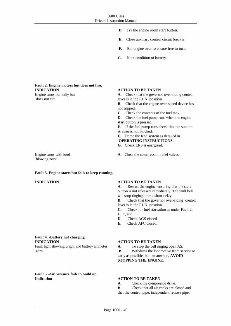
D. Try the engine room start button.
E. Close auxiliary control circuit breaker.
F. Bar engine over to ensure free to turn.
G. Note condition of battery.
Fault 2. Engine motors but does not fire.
INDICATION ACTION TO BE TAKEN
Engine turns normally but
does not fire.
A. Check that the governor over-riding control
lever is in the RUN position.
B. Check that the engine over-speed device has
not tripped.
C. Check the contents of the fuel tank.
D. Check the fuel pump runs when the engine
start button is pressed.
E. If the fuel pump runs check that the suction
strainer is not blocked.
F. Prime the feed system as detailed in
OPERATING INSTRUCTIONS.
G. Check ERS is energized.
Engine turns with loud
blowing noise.
A. Close the compression relief valves.
Fault 3. Engine starts but fails to keep running.
INDICATION ACTION TO BE TAKEN
A. Restart the engine, ensuring that the start
button is not released immediately. The fault bell
will stop ringing after a short delay.
B. Check that the governor over-riding control
lever is in the RUN position.
C. Check for fuel starvation as under Fault 2,
D, E, and F.
D. Check AGS closed.
E. Check AFC closed.
Fault 4. -Battery not charging.
INDICATION ACTION TO BE TAKEN
Fault light showing bright and battery ammeter
zero.
A. To stop the bell ringing open AS.
B. Withdraw the locomotive from service as
early as possible, but, meanwhile, AVOID
STOPPING THE ENGINE.
Fault 5.-Air pressure fails to build up.
Indication ACTlON TO BE TAKEN
A. Check the compressor drive.
B. Check that all air cocks are closed and
that the control pipe, independent release pipe,
1600 Class
Drivers Instruction Manual
Page 1600 - 41
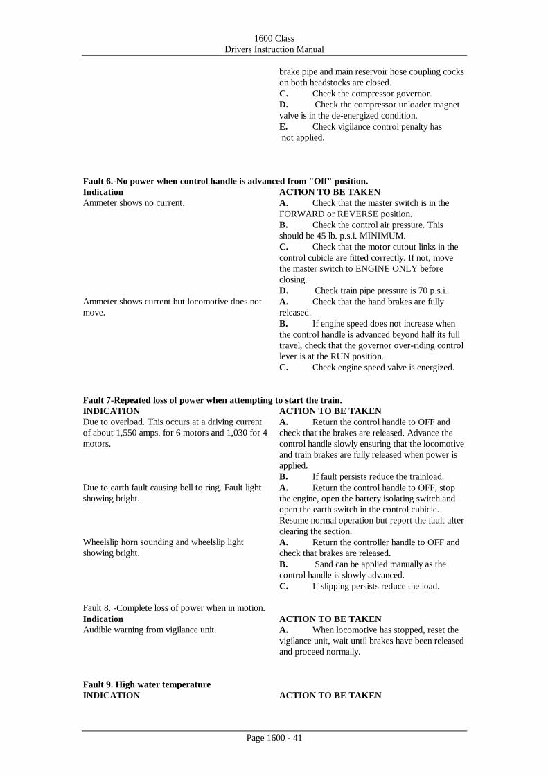
brake pipe and main reservoir hose coupling cocks
on both headstocks are closed.
C. Check the compressor governor.
D. Check the compressor unloader magnet
valve is in the de-energized condition.
E. Check vigilance control penalty has
not applied.
Fault 6.-No power when control handle is advanced from "Off" position.
Indication ACTlON TO BE TAKEN
Ammeter shows no current. A. Check that the master switch is in the
FORWARD or REVERSE position.
B. Check the control air pressure. This
should be 45 lb. p.s.i. MINIMUM.
C. Check that the motor cutout links in the
control cubicle are fitted correctly. If not, move
the master switch to ENGINE ONLY before
closing.
D. Check train pipe pressure is 70 p.s.i.
Ammeter shows current but locomotive does not
move.
A. Check that the hand brakes are fully
released.
B. If engine speed does not increase when
the control handle is advanced beyond half its full
travel, check that the governor over-riding control
lever is at the RUN position.
C. Check engine speed valve is energized.
Fault 7-Repeated loss of power when attempting to start the train.
INDICATION ACTION TO BE TAKEN
Due to overload. This occurs at a driving current
of about 1,550 amps. for 6 motors and 1,030 for 4
motors.
A. Return the control handle to OFF and
check that the brakes are released. Advance the
control handle slowly ensuring that the locomotive
and train brakes are fully released when power is
applied.
B. If fault persists reduce the trainload.
Due to earth fault causing bell to ring. Fault light
showing bright.
A. Return the control handle to OFF, stop
the engine, open the battery isolating switch and
open the earth switch in the control cubicle.
Resume normal operation but report the fault after
clearing the section.
Wheelslip horn sounding and wheelslip light
showing bright.
A. Return the controller handle to OFF and
check that brakes are released.
B. Sand can be applied manually as the
control handle is slowly advanced.
C. If slipping persists reduce the load.
Fault 8. -Complete loss of power when in motion.
Indication ACTION TO BE TAKEN
Audible warning from vigilance unit. A. When locomotive has stopped, reset the
vigilance unit, wait until brakes have been released
and proceed normally.
Fault 9. High water temperature
INDICATION ACTION TO BE TAKEN

1600 Class
Drivers Instruction Manual
Page 1600 - 42
Water temperature indicator light bright and fault
bell ringing.
A. If possible reduce power. Stop the
locomotive when convenient but leave engine
running.
B. Check water level and if low, but visible,
top up.
C. Check that fan is running.
.
Fault 10. Low Water level.
INDICATION ACTION TO BE TAKEN
Water level indicator light bright and fault bell
ringing.
A. Top up the engine water system. An
emergency filling point is situated or, top of the
header tank.
CAUTION.-Do not add cold water if sight glass
shows empty
Fault 11 Low oil pressure.
INDICATION ACTION TO BE TAKEN
Oil pressure indicator light bright and fault bell
ringing.
A. Check the reading on the lubricating oil
pressure gauge. If reading is below 25 p.s.i. stop
the engine. The locomotive is a failure. If the
reading is above 25 p.s.i. proceed to clear the main
line and check the level of the lubricating oil in the
engine sump. If necessary, top up.
B. Check that radiator cooling fan is
running.
Fault 12. Engine Stops.
INDICATION ACTION TO BE TAKEN
A. Ensure main control circuit breaker is
closed.
B. Reset engine overspeed trip if it has
operated.
C. Check as in Fault 1 and 2.