160899 kb2 eng revised 1kawamoto-pump.co.th/en/catalog/kb2-technical-handbook.pdf1hjdwlyh vxfwlrq...
TRANSCRIPT

Stainless / Constant Pressure Water Supply
NEW PUMPER KB
TECHNICAL HANDBOOK BY PRESSURE SENSOR BOOSTER PUMP
(Published in 2016)
KB2 Type Alternate / Alternate & Parallel Operation
KAWAMOTO PUMP ASIA CO., LTD.
Stainless precision casting Compact design Energy-saving operation Easy maintenance Silent design with low operation
sound Standard installation of total enclosed
fan cool

1. Features ① Stainless precision casting
Stainless precision casting is adopted for the pump casing and flange etc., and there is no concern about deformation. As for material of water contact section, mainly stainless and resin/bronze parts are adopted, so there is no worry about rust.
② Compact design Compact horizontal multi-stage pump is adopted, and the design is compact and space-saving with the low height of the unit.
③ Energy-saving operation (P.A.T) As for the operation at the time of conveying a small amount of water, the starting frequency is 60 times/hour or less, and the optimum operation time (10-30 seconds/10-90 seconds) was adjusted, so a water supply with a high energy-saving effect was achieved. As for the Alternative&Parallel operation type, it is possible to implement the operation with less gap between parallel/parallel off flows because of the operation time of the parallel pump and adjustment function of the parallel off flow.
④ Safety design Standard installation of the fully-closed motor that is secure against dust, humidity etc. The real time and secure sensor control by the microcomputer based on the pointless and trustable pressure and flow sensors data ofthe pump’s operation electric current value and water tank. The system design is secure even in the case of trouble because the retry function (*) and automatic alternative operation function are fitted. (*) Retry function: In the case that failure of the water supply is detected after the pump starts operating, do not worry immediately and implement the automatic alternative operation, and if failure of the water supply is detected again after the pump restarts, implement the failure display and signal output. If the water supply recovers after restarting, returnto normal operation.
⑤ Abundant functions The digital electric current display, failure mode No. display, electronic alarm buzzer and level sensor are fitted. The operation status of the pump is an individual display and easy to understand, and maintenance in the case of trouble is easy because of the intelligent alarm function.
⑥ Silent design with low operation sound The original stainless multistage pump that has a low sound pump is adopted for the main pump. The impeller is a cast 3D impeller with efficiency is high, and the silent operation.
⑦ Constant pressure water supply The starting frequency while supplying water is low and the water supply pressure is stable because of the original operation method with the pressure sensor and individual flow sensors for each pump.
⑧ Adoption of pointless circuit (alternative/alternative¶llel: 3.7kW or lower) A pointless sensor is adopted for the signals of pressure, flow, and tank level that are necessary foroperational control, so a trustable control is implemented.
⑨ Adoption of a shock-less valve to prevent water hummer The stainless shock-less valve with bypass to prevent water shock is adopted for the check valve, to prevent water hammer.
⑩ It is possible to install a heater to prevent freezing (*) A length for piping section in theunit is necessary.

2. Standard specification
Control method Constant pressure water supply by pressure sensor and flow sensor
Special specification Change the position of the control panel (Please consult with us) Special control panel specification (3-phase 200V 0.75kW or higher) BK type with vibration-proof stage Special accessory Vibration-proof stage Pump cover Anti-freezing heater Circuit for positive suction electromagnetic valve (electric valve) (in the control box) Connecting curved tube (to change the discharge direction) Electrode holder Electrode Foundation bolt
Operation method Alternate / Alternate & Parallel
Installation location Outdoor
Liquid lifting Clean water, 0-40℃ (Not frozen)
Pump (Material)
Stainless multistage turbine pump (Impeller: Resin, SCS13 or CAC406 (Bronze)) (Main Material : Water section SUS304, Casing: SCS13)
Motor Total Enclosed fan cool outdoor Synchronous rotation speed 50Hz: 3,000min1
Total Suction head condition
Positive suction: 0-5m, 0-3, (40-5.5kW, 50-7.5kW) Negative suction: Suction lifting height 6m.Suction actual lifting height 4m or less
Power source 1PH220V or 3PH380V Companion flange
shape JIS10K type
Paint colour (Munsell No.)
Pump, Piping: Silver Control panel: Grey (5Y7/1) Accumulator: Grey (10Y5.5/0.5) Others: Grey (2.5PB5.1/0.8)
Standard specification forthe control panel
Shape ECFW-A-S ECFW-P-S
Operation method Alternate Alternate & Parallel Rated voltage 1PH220V or 3PH380V
Box material (Plate thickness) Box type: Steel plate (1.2t) Installation location Outdoor
Voltage/Electric current type Digital display Motor protection Electronic thermal
Liquid level relay 3.7kW or lower, 5P+3P (for inflow electromagnetic
valve) 5.5/7.5kw 5P
Fu
nct
ion
Alarm buzzer ◯ Automatic alternative operation at the time of failure ◯
Water supply failure (Detection of water supply failure)
◯
Starting frequency automatic adjustment ◯ Alternative / Alternative & Parallel operation
automatic adjustment - ◯
Water supply failure retry ◯
Ind
ica
tion
lam
p
Power source ◯ (Red) Operation mode (manual/stop/automatic) ◯ (Red)×3
Selection pump (No.1/No.2/No.1&2) ◯ (Red)×3 Operation (Individual) ◯ (Red)×2
Failure (Individual) ◯ (Orange)×2 Water supply (Individual) ◯ (Red)×2
Water full ◯ (Orange) Water empty ◯ (Orange) (*1)
Ext
ern
al s
igna
l (*
2)
Operation ◯ (Individual) ◯ (Individual) Failure ◯ (Individual) ◯ (Individual)
Water full ◯ ◯
Water empty ◯ ◯ Water decreasing ◯ ◯
Inflow electromagnetic valve 3.7kW or lower ◯
5.5/7.5kW - (*1) When the water is decreasing: Blinks for 1 second, or when the electromagnetic valve is operating: Blinks 2 times and OFF for 1 second (*2). No voltage signal.

3. Application chart/Specification table 50Hz Application chart/Specification table Application chart
● Single/Alternate operation
● Alternate & Parallel operation
Specification table Stopping flow: 10L/min
Unit bore
Suction bore
Op
era
tion
mo
de
Model Mo
tor Standard specification Starting
pressure (*3) Selection range
Accumulator pressure
Noise
Discharge TDH Starting pressure
Stopping pressure
mm mm kW M3/min m MPa{kgf/cm2} MPa{kgf/cm2} MPa{kgf/cm2} MPa{kgf/cm2} dB(A)
40 32
Alte
rnat
e
KB2-325AE0.4T (*1) 0.4 0.06 22 0.22 {2.2} 0.28 {2.9} 0.15 {1.5} 0.12 {1.2} 42 KB2-325AE0.75S2 (*2) 0.75 0.06 32 0.31 {3.2} 0.39 {4.0} 0.22 {2.2} 0.17 {1.7} 52 KB2-325AE0.75 0.75 0.06 32 0.31 {3.2} 0.39 {4.0} 0.22 {2.2} 0.17 {1.7} 50 KB2-325LAE1.1 1.1 0.06 44 0.43 {4.4} 0.52 {5.3} 0.29 {3.0} 0.25 {2.5] 49 KB2-325AE1.1 1.1 0.065 53 0.52 {5.3} 0.65 {6.6} 0.36 {3.7} 0.29 {3.0} 51
40 40
KB2-405AE0.75 (*1) 0.75 0.16 16 0.16 {1.6} 0.24 {2.4} 0.12 {1.2} 0.088 {0.9} 46 KB2-405AE1.1 1.1 0.17 25 0.25 {2.5} 0.31 {3.2} 0.18 {1.8} 0.14 {1.4} 50 KB2-405AE1.5 1.5 0.16 30 0.29 {3.0} 0.35 {3.6} 0.22 {2.2} 0.17 {1.7} 53 KB2-405AE2.2 2.2 0.16 44 0.43 {4.4} 0.51 {5.2} 0.32 {3.3} 0.25 {2.5} 50 KB2-405AE3.7 3.7 0.165 65 0.64 {6.5} 0.73 {7.4} 0.49 {5.0} 0.34 {3.5} 54 KB2-405AE5.5 5.5 0.19 80 0.78 {8.0} 0.92 {9.4} 0.59 {6.0} 0.44 {4.5} 57
40 50
KB2-505AE1.5 (*1) 1.5 0.22 22 0.22 {2.2} 0.29 {3.0} 0.15 {1.5} 0.12 {1.2} 50 KB2-505AE2.2 2.2 0.25 32 0.31 {3.2} 0.44 {4.5} 0.24 {2.4} 0.20 {2.0} 51 KB2-505AE3.7 3.7 0.24 48 0.47 {4.8} 0.50 {6.0} 0.32 {3.3} 0.27 {2.8} 55 KB2-505AE5.6 5.5 0.25 55 0.64 {6.5} 0.74 {7.6} 0.43 {4.4} 0.34 {3.5} 58
50 65 KB2-655AE3.7 3.7 0.37 32 0.31 {3.2} 0.41 {4.2} 0.23 {2.3} 0.17 {1.7} 56 KB2-655AE5.5 5.5 0.325 48 0.47 {4.8} 0.56 {5.7} 0.29 {3.0} 0.25 {2.5} 60 KB2-655AE7.5 7.5 0.375 60 0.50 {6.0} 0.68 {6.9} 0.43 {4.4} 0.31 {3.2} 62
40 32
Alte
rnat
e &
par
alle
l
KB2-325PE0.4T (*1) 0.4×2 0.12 22 0.22 {2.2} 0.28 {2.9} 0.15 {1.5} 0.12 {1.2} 45 KB2-325PE0.75S2 (*2) 0.75×2 0.12 32 0.31 {3.2} 0.39 {4.0} 0.22 {2.2} 0.17 {1.7} 54 KB2-325PE0.75 0.75×2 0.12 32 0.31 {3.2} 0.39 {4.0} 0.22 {2.2} 0.17 {1.7} 52 KB2-325LPE1.1 1.1×2 0.12 44 0.43 {4.4} 0.52 {5.3} 0.29 {3.0} 0.25 {2.5] 51 KB2-325PE1.1 1.1×2 0.13 53 0.52 {5.3} 0.65 {6.6} 0.36 {3.7} 0.29 {3.0} 53
50 40
KB2-405PE0.75 (*1) 0.75×2 0.32 16 0.16 {1.6} 0.24 {2.4} 0.12 {1.2} 0.088 {0.9} 49 KB2-405PE1.1 1.1×2 0.34 25 0.25 {2.5} 0.31 {3.2} 0.18 {1.8} 0.14 {1.4} 52 KB2-405PE1.5 1.5×2 0.32 30 0.29 {3.0} 0.35 {3.6} 0.22 {2.2} 0.17 {1.7} 55 KB2-405PE2.2 2.2×2 0.32 44 0.43 {4.4} 0.51 {5.2} 0.32 {3.3} 0.25 {2.5} 52 KB2-405PE3.7 3.7×2 0.33 65 0.64 {6.5} 0.73 {7.4} 0.49 {5.0} 0.34 {3.5} 56 KB2-405PE5.5 5.5×2 0.38 80 0.78 {8.0} 0.92 {9.4} 0.59 {6.0} 0.44 {4.5} 60
65 50
KB2-505PE1.5 (*1) 1.5×2 0.44 22 0.22 {2.2} 0.29 {3.0} 0.15 {1.5} 0.12 {1.2} 53 KB2-505PE2.2 2.2×2 0.5 32 0.31 {3.2} 0.44 {4.5} 0.24 {2.4} 0.20 {2.0} 54 KB2-505PE3.7 3.7×2 0.48 48 0.47 {4.8} 0.50 {6.0} 0.32 {3.3} 0.27 {2.8} 57 KB2-505PE5.5 5.5×2 0.5 55 0.64 {6.5} 0.74 {7.6} 0.43 {4.4} 0.34 {3.5} 61
80 65 KB2-655PE3.7 3.7×2 0.74 32 0.31 {3.2} 0.41 {4.2} 0.23 {2.3} 0.17 {1.7} 58 KB2-655PE5.5 5.5×2 0.65 48 0.47 {4.8} 0.56 {5.7} 0.29 {3.0} 0.25 {2.5} 62 KB2-655PE7.5 7.5×2 0.75 60 0.50 {6.0} 0.68 {6.9} 0.43 {4.4} 0.31 {3.2} 64
Note) *1: Specialized for inflow *2: 1PH220V *3: Minimum starting pressure adjustable from the standard starting pressure. The noise is the maximum value within the specification. The stopping pressure is a reference.
Flow rate (m3/min) Flow rate (m3/min)
To
tal H
ead
(m)
To
tal H
ead
(m)
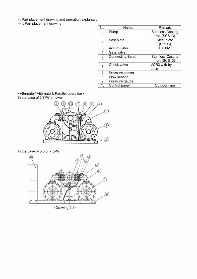
4. Part placement drawing and operation explanation 4-1. Part placement drawing
No. Name Remark
1 Pump Stainless Casting
iron (SCS13)
2 Baseplate Steel plate
(SPHC) 3 Accumulator PTD3-1 4 Gate valve
5 Connecting Bend Stainless Casting
iron (SCS13)
6 Check valve VCR3 with by-
pass 7 Pressure sensor 8 Flow sensor 9 Pressure gauge 10 Control panel Outdoor type
<Alternate / Alternate & Parallel operation> In the case of 3.7kW or lower
In the case of 5.5 or 7.5kW
<Drawing 4-1>

4-2. Operation Theory
4.1 Alternate operation
(1) When water is used while the pump is stopped and the pressure drop to P1, the pressure sensor detects the pressure, and pump
starts. (2) The water supply continues operation between A and B on the unit performance curve while the used water rate is between Q1 and Q2. (3) When the used water rate drops to Q1 or less, the flow rate sensor detects the flow, and the pump stops. <Single operation> <Alternative operation> (4) Repeat step (1) to (3). (4) The No. 1 and No. 2 pumps alternately repeat steps (1) to (3)
4.2 Alternate-Parallel operation
(1) When water is used while the pump is stopped and the pressure drop to P1, the pressure sensor detects the pressure, and pump
starts. (2) The water supply continues operation between AB on the unit performance curve while the used water rate is between Q1 and Q3. (3) When the used water rate drop to Q1 or less, the flow rate sensor detects the flow, and the pump stops. (4) If the used water rate is less than Q3, alternate operation will be repeated. (5) If the used water rate rises to Q3 or more during the operation of the first unit, the pressure will drop below P1 again. The second
pump will start, and operation will start. (6) If the used water rate drops to Q2 or less during parallel operation, the pump the started last will stop, and alternate operation will
start.
Unit performance curve
Capacity (m3/min)
Net
pum
p he
ad
Q1 = Stop flow rate (0.01m3/min) Q2 = Max. flow rate P1 = Starting pressure
Pum
p st
arts
Pum
p st
ops
No.
1 p
um
p st
arts
No.
1 p
um
p st
ops
No.
2 p
um
p st
arts
No.
2 p
um
p st
ops
Drop to starting head
Flow rate drops
Drop to starting head
Flow rate drops
Drop to starting head
Flow rate drops
Q1 = Stopped flow rate (0.01m3/min) Q2 = Parallel off flow rate Q3 = Parallel flow rate Q4 = Max. flow rate P1 = Starting pressure, Parallel pressure
Unit performance curve (first unit)
Unit performance (second units)
Capacity (m3/min)
Net
pum
p he
ad

Drop to starting head
Flow rate drops
Drop to starting head
Flow rate drops
Flow rate increases Drops to parallel (Start) pressure
Flow rate drops
(Parallel)
Flow rate drops
(Parallel off)
Drop to starting head
No
. 1 p
ump
star
ts
No
. 1 p
ump
stop
s
No
. 2 p
ump
star
ts
No
. 2 p
ump
stop
s
No
. 2 p
ump
star
ts
No
. 1 p
ump
stop
s N
o. 2
pum
p st
ops
Th
e ne
xt t
ime,
op
erat
ion
sta
rts
from
th
e p
ump
wh
ich
ent
ere
d pa
ralle
l off
first
(pu
mp
No
. 1
)

5. Detail of features 5-1. Stainless precision casting A stainless precision casting is adopted for the pump casing and flange, so the strength against stress and deformation is stronger than stainless sheet parts. And since the stainless steel products, there is no worry about rusty water, it can supply with clean water.
<Drawing 5-1> References (1) Features of the “lost wax method”, the casting method of stainless precision casting adopted for Pumper KB 1 It is possible to form an integrated molding into a
complicated shape 2 It is possible to achieve a casting with good mechanical
characteristics 3 The dimensional precision and surface roughness are
good 4 Because the fluidity is good, a thin wall design is
possible. 5 Compared to stainless sheet parts, Higher strength and strong resistance against piping stress. Excellent shape flexibility No corrosion cracks due to stress
Parts adopted for Pumper KB ・Casing ・Piping, Check valve ・Casing cover ・Flange
⌾: Excellent○: Good △: Inferior
Item Lost wax Sand mould
casting
Mold cost △ ⌾
Molddurability ⌾ △
Dimensional precision ○ △
Surface roughness ○ △
Shape difficulty ⌾ △
Price △ ○
(2) Process: Explanation with a bolt with a simple structure (It has not been manufactured in fact)
Check valve (SCS13) Exhaust valve (SUS304)
Pressure gauge
Pressure sensor
Flow sensor
Connecting bend (SCS13)
Ball valve (C3771)
Pump (SCS13)
Flexible Joint (SUS304)
Stainless
CAC (BC) or copper alloy Resin
① Manufacturing of mould
: Mould
Mould Mould
Model
②Structure of model Create a model by injecting wax into the mould.
Take the model out of the mould
③ Coating Cover a model bolt with a refractory material (repeat a few times) and make a casting mould.
: Coating
Model
Casting mould
Heat
Heat
Liquid wax
Heat
Heat
④Dewaxing Once the coating work is completed, heat the wax inside casting mold and liquidate. (This is why this method is called the “lost wax method.”)
⑤ Casting Pour in the stainless material
Casting mold
⑥ Finishing work 1. After casting, break the casting mold and remove
the“casting”. 2. Finish by implementing surface finishing etc.
FG
<Drawing 5-2> <Drawing 5-3> <Drawing 5-4>
<Drawing 5-5> <Drawing 5-6> <Drawing 5-7>
Wax
Wax
S
tain
les
s

5.2Compact design A small multistage turbine pump has been adopted for the main pump, and the unit became compact. <Alternate / Alternate & Parallel, 3.7kW or lower> Base dimensions: 760mm×535mm Unit height: 490mm < Alternate / Alternate & Parallel, 5.5/7.5kW> Base dimensions: 1000mm×650mm Unit height: 590mm
<Drawing 5-9: In the case of Alternate /Alternate & Parallel, 3.7kW or lower>
<Drawing 5-9: In the case of Alternate / Alternate & Parallel, 5.5/7.5kW >

5-3. Energy saving operation (1) Achieve water supply with high energy saving effect by suppressing the starting frequency being 60
times/hour or less, and changing the forcible operation time to 10-30 seconds normally (adjusting to 10-90 seconds if that the starting frequency is high).
<①Starting frequency: Within 30 times/1 hour> The pump operation time is 10-30 seconds.
<②Starting frequency: 30 times or more/1 hour> The pump operation time is 10-90 seconds, and the starting frequency is suppressed to 60 times or less/1 hour together with ①.
(2) In the alternate & parallel operation type, energy saving is achieved by adjusting the parallel off flow
to the optimum flow by the electric current control, and operation with less gap between the parallel flow and parallel off flow. (The parallel off flow is calculated by detecting the electric current of each pump during a shutdown period and the electric current of each pump at the time of parallel starting)
Operating
Stop
30s timer 30s timer <Drawing 5-11>
90s timer <Drawing 5-12>
Operating Stop
Starting pressure Electric current
<Drawing 5-13>
Par
alle
l off
flow
Par
alle
l flo
w

5-4. Control panel with abundant functions (Alternate / Alternate & Parallel operation) 1) Functions of the control panel The operation status of pump is displayed on the panel on the control panel.
Intelligent alarm (List of individual digital displays)
Status
Digital display
Content of the display
Power ON 0 0
Operating
0 0 Stop status
0-9
1-5
0-9
0-9
Current value: In the case of 9.9A or lower In the case of 10A, Max. 50A
3 0
8 V
Current value: i.e. In the case of 380V
Current value Parallel OFF current value (only alternative¶llel operation). The point at the right end turns ON (*)
Failure mode (Blinking display)
0 0 Abnormality of power (Open-phase of S-phase, Abnormality of frequency)
0 1 Phase-sequence reversal of power 1 0 Overload 1 1 Restriction 2 0 MC open 2 1 MC short
3 0 Failure of the water supply
4 0 Abnormality of the flow sensor Cumulative time H1 or H2 Unit: Hour, Maximum 6 digits Number of times startingandtotal
C1 or C2 Unit: Number of times, Maximum 8 digits
Failure history E1 or E2 For 4 times
(*) Parallel OFF with illumination for 3 seconds or longer (The parallel operation continues if shorter than 3 seconds) Other functions (In the case of Alternate / Alternate & Parallel operation) ・With warning buzzer (at the time of failure) ・Indication lamp for water level in the water tank (Overflow , Dry (Empty)) ・Monitor lamp indication of operation/failure/water supply ・No voltage terminal output (running /failure/overflow/dry(empty))
Voltage Current, Operation time, Number of times starting (individual) Failure display (List of digital displays)
Power source light
Over flow light
Dry (Empty) light (Note 1)
Individual running lamp
Individual failure/ trouble lamp
Individual water supply indication lamp
Display select switch
Buzzer “ON-OFF” switch
Pump selection switch
Selected pump lamp
Operation mode selection switch
Operation mode lamp Reset
(Note 1) Status of empty indication light ON Empty status
Blinking (1 second) Water decreasing
Blinking with various speeds (Blinking: 2 times, Stop: 1 time)
The inflow electromagnetic valve operates
<Drawing 5-14> Alternate / Alternate &Parallel operation

2) Comparison table between ECFW-S and other companies ⌾Excellent○Good △Equal☓Inferior
Item ECFW-A/P-S Company A Company B Pump control Main circuit switch ○ Electromagnetic contact ○ Electromagnetic contact ○ Electromagnetic contact Rotary operation ○ Possible ○ Possible ○ Possible Alternatein case of failure
○ Possible ○ Possible ○ Possible
Start ○ Pressure sensor ⌾ Pressure transmitter ⌾ Pressure transmitter Stop ⌾ Individual pump flow sensor △
○ Pressure transmitter (Pressure increase) (Discharge pressure constant method) Flow switch (Constant pressure method)
△ ○
Pressure transmitter (Pressure increase) (Discharge pressure constant method) Flow switch (Constant pressure method)
Advance interlock ⌾ 30/90 seconds from the last stop
○ Fixed as 60 seconds It is possible to change to 0/30/120 seconds on the panel
○ From pressure increase or small flow→Automatic adjustment
Parallel start ○ Pressure sensor Interval of 3 seconds
○ Pressure sensor Interval of 5 seconds
○ Pressure sensor Interval of 5 seconds
Parallel off ⌾ Electric current digital sampling Optimum parallel off control
○ Pressure & electric current detection Fixed, adjustable by the volume
○ Flow switch detection Parallel off flow=fixed
Parallel interlock ⌾ 30/60seconds from the last parallel off
○ Fixed as 10 seconds It is possible to change to 0/5/20 seconds on the panel
- Unknown
Liquid level control
Overflow ○ Indication LED ON (1 second delay)
○ Indication LED ON ○ No indication LED Abnormality No. 01
Empty ⌾ Indication LED ON (1 second delay) Automatic operation available by turning E2 (automatic recovery water level) ON with the power ON during empty reset
○ Indication LED ON ○ No indication LED Abnormality No. 02 Operateby turning E2 (automatic recovery water level) ON with the power ON
Interface Main switch ⌾ Push switch * (With answer
back) ○ Rocker switch ○ Rocker switch
Select switch ⌾ Push switch * (With answer back)
△ Rocker switch ○ Dip switch in the panel
Failure reset switch ○ Push switch △ None ○ Push switch Manual operation of parallel model
○ Parallel operation (For pressure reducing valve balance check)
△ Alternative operation Rocker switch
⌾ Individual single/parallel operation Individual push switch
Indication function Power LED ○ Has ○ Has ○ Has Running LED ○ Pump individual LED ○ Pump individual LED ○ Pump individual LED Failure LED ○ Pump individual LED ○ Pump individual LED △ ON at the time of failure, only 1 Phase-sequence reversal LED
○ None=Unnecessary ○ Has ○ None=Unnecessary
AbnormalityLED ○ None=Unnecessary △ None ○ None=Unnecessary Pressure monitor △ None (Pressure gauge) ○ Starting pressure ON
indication (ON) Stopping pressure OFFindication (ON)
⌾ Digital pressure gauge However, common with abnormal indication
Water supply monitor ⌾ Pump individual = For water supply check
△ None △ None
Electric current meter ⌾ Pump individual, digital 2 digits, Failure mode No. indication
△ Variation support ☓ None
Alarm buzzer ○ Small electronic type △ Variation support ○ Has Protective function Power S-phase open-phase
⌾ Failure mode 00, Inoperable △ None △ None
Power phase-sequence reversal
⌾ Failure mode 01, inoperable ○ Phase-sequence reversal LED ON Automatic/Manual operation operable
○ Abnormality No. Reversing switch
Overload ⌾ Failure mode 10 Cooling time: 60 seconds CT detection
○ Failure LED ON - Unidentifiable CT detection
○ Abnormality No. (Individual) Common for two pumps 2E thermal relay
Restriction ⌾ Failure mode 11 Cooling time: 60 seconds
○ Failure LED ON - Unidentifiable
○ Abnormality No. (Individual)
SSC, MC open ⌾ Failure mode 20 ○ Failure LED ON △ No function SSC, MC short ○ Failure mode 21 △ Failure LED ON ☓ No function Water supply interruption
⌾ Failure mode 30 Retry 2 times Parallel type: Water supply suspension of only 3 seconds
☓ None ○ Abnormal low pressure (Individual)
Sensor abnormality ⌾ Failure mode 40 At the time of failure of the flow sensor
△ None (Unnecessary) ○ Pressure setting abnormality 06 Starting/Stopping pressure = At the time of reversal
* The buzzer rings if it is set.

5-5. Silent design 5-5-1) Pump section 1. The noise is reduced by adopting a high efficiency cast 3D impeller. 2. By adopting a multistage pump, the power per impeller reduces, the variation of water flow is less, and the flowing water and collision noisesare reduced. 3. Because of the double-casing, any noise from the impeller section and guide vane is contained directly. Therefore, the flowing water noise of main body of pump is barely audible.
Comparison of features of the 3D
impeller
[Models to be compared: 406-3.7] ⌾:Excellent○: Good ☓:Inferior Item KR5-C Company A Company B
Ma
teria
l & S
tru
ctu
re Number of stages 3 3 4
Material Impeller Resin SUS304 (Press) Resin Impeller hub CAC406 (BC6) SUS304 (Press) Resin
Wing Shape 3D 2D 2D
Manufacturing method Casting by
injection (P.A.T) Press + Welding
Injection + Ultrasonic welding
Driving method Width across flat Width across flat Width of flat
Eva
lua
tion
Strength
Resistance against centrifugal stress *1
○ ⌾ ○
Around boss *2 ⌾ ⌾ ☓
Strength ○ (Integrated with
resin) ⌾
☓(Attached to
resin)
Balance ⌾ ○ ○
H-Q performance ⌾ ○ ○
Noise feature ⌾ ○ ○
Surface roughness ⌾ ⌾ ⌾
Saturation axis power curve *3 ⌾ ○ ○
Support for suction specification (For the main pump) ⌾ ⌾ ☓
*1: The centrifugal stress on the impeller is proportional to the impeller’s specific gravity.
*2: Fatigue strength, Creep strength, Toughness *3: The optimum item for control of the automatic water supply
Specific gravity: Resin [KR4/5-C] (1.2) < Resin [Company B] (1.66) < Stainless (7.2) Young rate: Resin [KR4/5-C] (5.5×10⁴kgf/cm2) < Resin [Company B] (1.3×10⁵)
Casing (SCS13)
Partition plate (SUS304)
Guide vane (Resin or CAC406 (BC6))
Impeller (Resin or CAC406 (BC6))
(Impeller hub CAC406 (BC6)
Guide vane (Resin or CAC406 (BC6))
Impeller (SCS13, Resin or CAC406 (BC6)) (Impeller hub CAC406 (BC6))
Casing cover (SCS13) Motor (IP54)
<Drawing 5-15>

5-6 Adoption of pointless sensor (1) Light sensor (Pressure sensor) ① Overview The detecting section consists of the LED and light reception transistor as in Drawing 5-16, which detects light because the light cutting plate is raised/ lowered according to the pressure, and it changes to an electrical signal, and turns ON/OFF.
<Comparison with a conventional pressure switch>
Item Conventional type Pressure sensor (Light sensor)
type Structure (Output)
Coil spring + Snap action (Contact)
Coil spring + Electronic circuit (Transistor)
Adjustment of the setting
pressure
Discriminates by sound LED indication
Differential pressure
0.02MPA (0.2kgf/cm2) or higher
Within 0.005MPa (0.05kgf/cm2)
②Features ・The adjustable pressure range is wider because the differential pressure is small ・The circuit in the control is simplified, achieving space and cost reduction ・There is no mechanical wear and the life is long because the pressure detecting section is a non- vibrating structure. ・The pressure setting value does not vary even if using for a long time.
LED
A Basic circuit
B Basic placement
Output
Light reception transistor
Light cutting plate <Drawing 5-16>
Light cutting plate
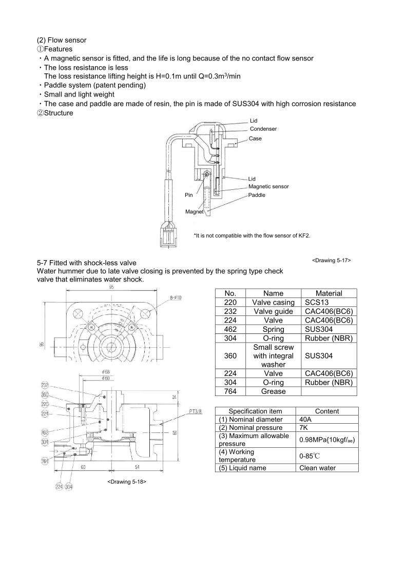
(2) Flow sensor ①Features ・A magnetic sensor is fitted, and the life is long because of the no contact flow sensor ・The loss resistance is less The loss resistance lifting height is H=0.1m until Q=0.3m3/min ・Paddle system (patent pending) ・Small and light weight ・The case and paddle are made of resin, the pin is made of SUS304 with high corrosion resistance ②Structure
5-7 Fitted with shock-less valve Water hummer due to late valve closing is prevented by the spring type check valve that eliminates water shock.
Lid
Condenser
Case
Lid Magnetic sensor
Paddle Pin
Magnet
*It is not compatible with the flow sensor of KF2.
No. Name Material 220 Valve casing SCS13 232 Valve guide CAC406(BC6) 224 Valve CAC406(BC6) 462 Spring SUS304 304 O-ring Rubber (NBR)
360 Small screw with integral
washer SUS304
224 Valve CAC406(BC6) 304 O-ring Rubber (NBR) 764 Grease
Specification item Content
(1) Nominal diameter 40A (2) Nominal pressure 7K (3) Maximum allowable pressure
0.98MPa{10kgf/ae)
(4) Working temperature 0-85℃
(5) Liquid name Clean water
<Drawing 5-17>
<Drawing 5-18>

6. Handling precautions
Points to be noted especially
1. Connect the grounding securely, and install a dedicated breaker. An electric shock may be caused
at the time of failure or electrical leakage. 2. Execute the electrical work safely and securely by complying with the electrical equipment
technical standard and interior wiring regulation. Electrical leakage or fire may result if wiring or connections are defective.
3. Check that suitable waterproofing and draining process are applied to the floor. Severe damage risk if a water leak occurs.
4. Do not implement insulation resistance measures for the control panel. The control board may be damaged.
6-1 Installation 1) Installation precautions
Warning
In the case of hanging at the time of unloading, carrying in or installation, implement after checking the weight of the device and how to hang according to the brochure, installation diagram, or operation manual. Do not hang a device whose weight is more than the rated load for a hanging tool. If hanging is incomplete, it causes of injury due to falling. ① At the time of transfer/carrying in, please hang at four points using hanging shackles in the hanging
holes (four points) on the base as in <Drawing 6-1>. If hanging on the accumulator etc., may result in damage.
② Install horizontally, and fix securely with suitable foundation bolts. If the foundation is not horizontal or uneven, the base might twist resulting in a failure. (Note 1) Please buy the foundation bolts separately. (Recommended bolt size: 4-M12×160) 2) Selection of the installation location
Caution
Do not install in a location lacking effective drainage and waterproofing. Severe damage risk if a water leak occurs. Do not install in a high humidity location, such as a bathroom. Any electrical leakage may cause an electric shock. Do not install in a location subject to hazardous materials, such as acid, alkali, solvent, paint or gas, or where corrosion may be generated, or a dusty place (i.e. chemical factory). Electrical leakage or a fire may occur. ① Please install in a cool location protected from rain or direct
sunshine and convenient for disassembly/assembly. ② If installing in a location subject to rain or direct sunshine it is
essential to fit the pump cover (special accessory). ③ Install in a location where the ambient temperature around the
pump does not exceed 40℃.
<Drawing 6-1>

6-2 Piping: For positive suction refer to <Drawing 6-2>, for Negative suction refer to <Drawing 6-3>.
Caution
Please do not let the pump suck foreign substance or sand, as this may damage the impeller lock or the mechanical seals. 1) Suction piping
<Common> ① Install suction piping for each pump, do not split half way. ② Make the piping as short as possible, with minimal bends. ③ For any risk of foreign substances or sand, install a suitable filter. <In the case of inflow> ①Install the gate valve for maintenance near the suction port. <In case of suction> ① Make the tip of the suction pipe deeper than the pipe’s diameter (D) by two times or more, and
separate it from the bottom by 30cm or more. ② Slope the suction piping to prevent air pockets. ③ Do not install a valve in the suction piping. ④ Loosen the bypass check valve counter clockwise by two rotations and apply a positive pressure
to each suction pipe.Also, make sure there is no leakage from the foot valve. 2) Discharge piping
① Install the sluice valve for maintenance near the suction port. ② Installation of piping for maintenance testing is recommended.
3) Common ① Install avibration-proof joint and piping support to avoid any direct load on the piping or the pump. ② To prevent freezing,cover the piping with heat insulating material. It is recommended to install a
heater (special accessory). If installing a heater on site, contact the supplier or the service provider designated by our Company.
4) Precaution concerning installation of the pump cover ① If installing a vibration-proof joint directly to the pump, it might contact the pump cover. In that
case, install a short pipe (15cm or longer) between the pump and the vibration-proof joint.
<Inflow> Piping for test
Vibration-proof joint Discharge piping
Piping retainer
60cm or longer
Pump cover (Special
accessory)
Drainage ditch
Short pipe (15cm or longer)
<Drawing 6-2>
<Suction> Piping for test
Vibration-proof joint Discharge piping
Pump cover (Special
accessory) Piping retailer
Suction piping Drainage ditch
Short pipe (15cm or longer)
20 o
r lo
nger
30cm
or
long
er
<Drawing 6-3>
Suction piping

6-3. Electrical work
Warning
Install a dedicated breaker at the power side to avoid the risk of electrical leakage, electric shock or a fire. Execute electrical work safely and securely by following the electrical equipment technical standard and interior wiring regulation. Electrical leakage or a fire may result if wiring or connections are defective. Implement the grounding work before turning on the electricity supply. Do not connect the grounding to a gas pipe, water pipe, lightning rod, or telephone grounding. An electric shock may result if the grounding is defective. 1) If the control panel does not have a breaker, install a breaker at the power
source. (For existence/nonexistence of a breaker, refer to the list in the“Control panel special specification” (P2).
2) Connect the power line to R.S (single phase)/R.S.T (3-phase) of the control panel.
3) There is a grounding terminal in the control panel to implement the installation work. Attach copper plate (30cm×30cm or bigger) or copper bar (Thickness: 1cm or thicker, Length: 40cm or longer), and bury it in wet ground by 30cm or deeper. When handling the grounding cable, turn OFF the main power.
6-4. Connection method For the water supply unit, the connections of the main parts (motor, pressure sensor, flow sensor) have been implemented already, so implement only the connections below, as necessary. 1) Liquid surface control
Caution
Do not operate if empty (operation without water in the tank). The water in the pump becomes hot that may cause damage. To prevent empty operation, install the tank’s liquid level control unit. To install the liquid level control unit, the parts in<Drawing 6-5> are required. In the case of the standard control panel for the single operation model, the LVS-1 control panel (special accessory) is required, as a separate purchase.
① Fit the electrode depending on the tank’s water level in <Drawing 6-5>. For operation of the level sensor, the water level gap may change due to the effect of water quality, so be aware.
② A short-circuit line has been installed between E1 and E3 at the time of factory shipment, remove it.
③ Connect by referring to the connection diagram in <Drawing 6-6>.
④ In the case of using EHC-3 or EHC-4 (resistance built-in electrode retainer), remove the internal resistance.
2) External signal The non-voltage output terminal for external signal connection to the monitoring panel etc. Connect by referring the terminal connection diagram in <Drawing 6-6>. 3) Electronic connection diagram <Drawing 6-6> is the example for the standard Alternative/Alternative& Parallel operation (3.7kW or lower). Refer to the connection diagram on the back side of the door for the single operation model 5.5kW or higher, or the special specification panel.
Copper wire
Soldering 30cm or longer
Copper bar
Copper plate
<Drawing 6-4>
Not to implement water full alarm Electrode retainer EHC-3N To implement water full alarm Electrode retailed EHC-4N To implement water full/water reducing alarm Electrode retainer EHC-5N
Electrode bar (1m)
Electrode separator
Nut
<Drawing 6-5> Please prepare two sets for the double water tank type
Com
mon
1
No. 1 operation
No. 2 operation
No. 1 failure
No. 2 failure
Full Empty
Inflow valve Open
<Power terminal> <External signal output terminal>
(No voltage) <Liquid level control terminal>
<Drawing 6-6>
(Note 1) In the case of using the electrode bar, please remove the short-circuit wire between E3 and E1. (Note 2) In the case of using the water tank water reduction detection, remove the short-circuit wire between E3 and E5. (Note 3) In the case of detecting water reduction, this status is indicated byblinking of the water empty lamp. (Blinks for one second). When the inflow valve is operating, flicker blinking is implemented. (Blinks of twice, stops for one second).
Empty
Full
Reducing Open Electromagnetic valve
Close
Com
mon
2
Com
mon
3
Reducing
Note.1
Note.2
(Output terminal/No voltage) (Contact capacity 250V-0.8A (Inductive load) (In the case of exceeding the contact capacity above use once with a relay.)

6-5. Operation
Warning
In the case of connecting or disconnecting wiring, shut OFF the power source, and confirm no electricity in order to avoid an electric shock. After turning the power ON, do not leave the door of the control panel open or touch the charging section. Do not operate the operation switch etc. with a wet hand, in order to avoid an electric shock or fire risk.
Caution
Do not use with any voltage other than the rated voltage,in order to avoid an electric shock or fire risk Do not run if empty (operation without water in the tank), or fully-closed operation (status without inflow/outflow of water in the pump) manually. The pump gets hot, and burn or failure may result. Do not put a finger or stick in the opening section of the motor while operating. Electric shock or injury may result. Do not touch the motor or control panel while operating or immediately after operating because it may be hot. A burn may result. Shut OFF the power source if not using for a long time. Electric shock, electric leakage, or fire may be caused by insulation degradation. Do not cover the pump or control panel with blanket or cloth or place an object on it. Electric leakage, fire, or injury may result. Check that there is water inside the pump. The heater may be disconnected, or a fire may result. 1) Before starting operation (1) Check connections
① Check that wiring is implemented correctly and the terminal screws are tightened securely. ② Check the power source.
(2) Check the piping ① Check that the bolts and nuts are tightened securely.
(3) Priming the pump
Caution
Implement priming correctly for each pump. If priming is not enough, empty operation may occur causing a failure. Turn the main power OFF when priming to avoid the risk of an injury.
① Check the water level in the water tank.
② Remove the rubber bush of the motor fan cover. <In the case of inflow>
③ Open the sluice valve at the suction port of the pump, and then open the
ventilation valve <Drawing 6-7>.
④ Rotate the edge axis of the motor with a flat-head screwdriver to release
any air in the impeller.
⑤ The priming is completed once water starts flowing vigorously from the
ventilation valve. <In the case of suction>
① Open the ventilation valve, remove the plug, and implement priming. ② Rotate the edge axis of the motor with a flat-head screwdriver to release any air in the impeller. ③ The priming is complete once air bubbles stop going out from the ventilation valve.
<Common> ① Close the ventilation valve, install the plug (in case of the suction), and rubber bush on the motor fan cover.
(4) Check the rotation direction <Single operation>
① Confirm that the switch on control panel is at “Stop”, and then turn the power ON. ② Repeat switching from “Manual” to “Stop” once or twice, and check the rotation direction.
The normal rotation direction is clockwise if looking from the motor side. ③ In the case of opposite rotation, turn off the main power, replace two phases out of the three phases at the power
side (only 3-phase). <Alternative/Alternative & Parallel operation>
① Turn the power ON after confirming that the wiring is correct. If the power source is normal, the electrical current is displayed as “0.0” (lighting) on the display panel. If the power source is abnormal, “00” or “01” is displayed (blinking) on the display panel, so correct the cause as follows; “00”: Open-phase of S-phase, abnormal frequency (only 3-phase) “01”: Phase-sequence reversal of power source (only 3-phase)
Plug
Exhaust valve
Connecting bend

②Confirm that the selector switch on the control panel is at “1”, turn to “Manual” and “Stop” and turn main switch ON and OFF once or twice and check the rotation direction of Pump 1. The normal direction of rotation is the right rotation as viewed from the motor side.
③Check the rotation direction of Pump 2 by setting the selectorswitch to “2”. (It is not possible to switch the selector switch if the main switch is not at “Stop” status)
④In the case of reverse rotation, turn OFF the main power, and reverse two motor cables out of the threemotor cables (3-phase).
2) Check the manual operation (1) Check the valves open/close.
Sluice valves of the unit discharge port and piping for test
→Close
Sluice valves of the unit suction port and accumulator
→ Open Ball valves of the pressure sensor and pressure gauge
<Single operation> (2) Set the switch to “Manual” and operate the pump. (3) When the pump pressure increases, open the test pipingsluice valve gradually and check that water comes out
from the piping vigorously. (If lifting does not start within a few minutes, set the switch to “Stop”, and implement priming again).
<Alternative/Alternative& Parallel operation> (2) Set the switch to “1” and main switch to “Manual”. (3) When the pump pressure increases, open the test piping sluice valve gradually and check that water comes out
from the piping vigorously. This time, one of the “Water supply” monitor lamps turns ON. (If lifting does not start within a few minutes, set the main switch to “Stop”, and implement priming again).
(4) After lifting is complete, close the sluice valve and set the main switch to “Stop”. (5) Check Pump 2 the same way. 3) Check of automatic operation <Single operation> (1)Set the switch to “Auto” <Alternative/Alternative & Parallel operation> (1) Set the select switch to “1/2”, and the main switch to “Auto”. (It is not possible to turn the main switch from
“Manual” to “Auto” directly. Switch after settingto “Stop”) <Common> (2) Open/close the testing sluice valve slowly and check that the pressure does not change drastically. (3) Close the sluice valve and check that the pump stops. (If the starting frequency suppression timer is operating in
closed status, the pump does not stop immediately, this is normal). (4) Repeat starting and stopping and check that the pump operates as per 4-2). (5) ForAlternative& Parallel operation, check that the pump starts after opening the sluice valve and the pressure
decreases, and the pump startsparallel operation (two-unit operation) when opening the sluice valve more. (6) If the test piping is not installed, check by opening/closing the sluice valve at the unit’s discharge port. 4) Adjustment of the pressure sensor: refer to <Drawing 6-9>.
The pressure sensor is set at the standard starting pressure (P.20, 21) at the time of factory shipment, but it is possible to adjust depending on the siteconditions. Adjust by following the procedure below. ① Operate the pump manually, supply water for a while, and then close the
sluice valve. ② Set the main switch to “Stop” to stop the operation. ③ Open the sluice valve gradually, andclose the sluice valveto adjustthe
pressure. ④ Adjust the pressure sensor according to the procedure below. ・If the red lamp is ON: Turn the screw at the top of pressure sensor
counterclockwise with a Philips head driver until the red lamp goes OFF, and then turn clockwise until the red lamp comes ON.
・If the red lamp is OFF: Turn clockwisethe screw at the top of pressure gauge turn clockwise until the red lamp turns ON.
<In the case of using for suction> Change the starting pressure by adjusting the pressure based on the formula below. Pressure after adjustment (Starting pressure)≦Standard starting pressure-Suction total lifting height (m)/10
Big setting value
Phillips head driver Red lamp
ON: Red lamp ON OFF: Red lamp OFF
<Drawing 6-9>

10.4 Adjustable range 1) 50Hz Operation
type
Unit bore
Suction bore Model
Motor Standard specification Pressure sensor
Flow rate TDH Starting pressure Adjustment range mm mm kW M3/min m MPa{kgf/cm2} MPa{kgf/cm2}
Alternate
40
32
KB2-325AE0.4T 0.4 0.06 22 0.22 {2.2} 0.22 {2.2} ~ 0.15 {1.5} KB2-325AE0.75S2 (*2) 0.75 0.06 32 0.31 {3.2} 0.31 {3.2} ~ 0.22 {2.2} KB2-325AE0.75 0.75 0.06 32 0.31 {3.2} 0.31 {3.2} ~ 0.22 {2.2} KB2-325LAE1.1 1.1 0.06 44 0.43 {4.4} 0.43 {4.4} ~ 0.29 {3.0} KB2-325AE1.1 1.1 0.065 53 0.52 {5.3} 0.52 {5.3} ~ 0.36 {3.7}
40
KB2-405AE0.75 (*1) 0.75 0.16 16 0.16 {1.6} 0.16 {1.6} ~ 0.12 {1.2} KB2-405AE1.1 1.1 0.17 25 0.25 {2.5} 0.25 {2.5} ~ 0.18 {1.8} KB2-405AE1.5 1.5 0.16 30 0.29 {3.0} 0.29 {3.0} ~ 0.22 {2.2} KB2-405AE2.2 2.2 0.16 44 0.43 {4.4} 0.43 {4.4} ~ 0.32 {3.3} KB2-405AE3.7 3.7 0.165 65 0.64 {6.5} 0.64 {6.5} ~ 0.49 {5.0} KB2-405AE5.5 5.5 0.19 80 0.78 {8.0} 0.78 {8.0} ~ 0.59 {6.0}
50
KB2-505AE1.5 (*1) 1.5 0.22 22 0.22 {2.2} 0.22 {2.2} ~ 0.15 {1.5} KB2-505AE2.2 2.2 0.25 32 0.31 {3.2} 0.31 {3.2} ~ 0.24 {2.4} KB2-505AE3.7 3.7 0.24 48 0.47 {4.8} 0.47 {4.8} ~ 0.32 {3.3} KB2-505AE5.6 5.5 0.25 55 0.64 {6.5} 0.64 {6.5} ~ 0.43 {4.4}
50 65 KB2-655AE3.7 3.7 0.37 32 0.31 {3.2} 0.31 {3.2} ~ 0.23 {2.3} KB2-655AE5.5 5.5 0.325 48 0.47 {4.8} 0.47 {4.8} ~ 0.29 {3.0} KB2-655AE7.5 7.5 0.375 60 0.50 {6.0} 0.50 {6.0} ~ 0.43 {4.4}
Alternate
& parallel
40 32
KB2-325PE0.4T 0.4×2 0.12 22 0.22 {2.2} 0.22 {2.2} ~ 0.15 {1.5} KB2-325PE0.75S2 (*2) 0.75×2 0.12 32 0.31 {3.2} 0.31 {3.2} ~ 0.22 {2.2} KB2-325PE0.75 0.75×2 0.12 32 0.31 {3.2} 0.31 {3.2} ~ 0.22 {2.2} KB2-325LPE1.1 1.1×2 0.12 44 0.43 {4.4} 0.43 {4.4} ~ 0.29 {3.0} KB2-325PE1.1 1.1×2 0.13 53 0.52 {5.3} 0.52 {5.3} ~ 0.36 {3.7}
50 40
KB2-405PE0.75 (*1) 0.75×2 0.32 16 0.16 {1.6} 0.16 {1.6} ~ 0.12 {1.2} KB2-405PE1.1 1.1×2 0.34 25 0.25 {2.5} 0.25 {2.5} ~ 0.18 {1.8} KB2-405PE1.5 1.5×2 0.32 30 0.29 {3.0} 0.29 {3.0} ~ 0.22 {2.2} KB2-405PE2.2 2.2×2 0.32 44 0.43 {4.4} 0.43 {4.4} ~ 0.32 {3.3} KB2-405PE3.7 3.7×2 0.33 65 0.64 {6.5} 0.64 {6.5} ~ 0.49 {5.0} KB2-405PE5.5 5.5×2 0.38 80 0.78 {8.0} 0.78 {8.0} ~ 0.59 {6.0}
65 50
KB2-505PE1.5 (*1) 1.5×2 0.44 22 0.22 {2.2} 0.22 {2.2} ~ 0.15 {1.5} KB2-505PE2.2 2.2×2 0.5 32 0.31 {3.2} 0.31 {3.2} ~ 0.24 {2.4} KB2-505PE3.7 3.7×2 0.48 48 0.47 {4.8} 0.47 {4.8} ~ 0.32 {3.3} KB2-505PE5.5 5.5×2 0.5 55 0.64 {6.5} 0.64 {6.5} ~ 0.43 {4.4}
80 65 KB2-655PE3.7 3.7×2 0.74 32 0.31 {3.2} 0.31 {3.2} ~ 0.23 {2.3} KB2-655PE5.5 5.5×2 0.65 48 0.47 {4.8} 0.47 {4.8} ~ 0.29 {3.0} KB2-655PE7.5 7.5×2 0.75 60 0.50 {6.0} 0.50 {6.0} ~ 0.43 {4.4}
*1 : Positive suction *2 : 1PH220V

6) Normal operation
Caution
Do not touch the motor. It is hot and may cause a burn. (1) Check the valves open/close
Sluice valve of the test piping, Ball valve of the pressure gauge
→Close
Suction port of the unit, Sluice valves at thedischarge port and accumulator
→ Open
Ball valves of the sluice valve and pressure sensor (2) Check the control panel.
Alternative&Parallel
operation
Main switch “Auto” Select switch “1.2”
6-6. Maintenance/Inspection
Warning
If the unit does not operate or there is an abnormality (burnt smell etc.), stop the operation immediately, shut off the power, and implement maintenance and inspection. Operating with an abnormality or a faultyrepair may result in an electric shock, fire, or water leakage. Ifthe gas pressure in the accumulator is low, refill with air. Filling with an explosive gas such as hydrogen gasmay cause an explosion.
Caution
When turning the power source OFF to prepare for a long-time stoppage, always drain the water in the pump.
If the power is turned OFF with water still in the pump, the heater for preventing function will not operate, and the pump could freeze rupture.
Use a 250V or less insulation resistance tester when measuring the insulation resistance. Failure to observe this could result in control panel damage.
Confirm that the inner pressure of the pump unit in zero before starting inspections. Water could spray out if there is residual pressure.
1) Daily inspection
Item Confirmation item Judgment standards Pump Water leaks from mechanical seals There is no dripping
Motor Outer temperature Ambient temperature + 70℃ or less Ball bearings No abnormal operating noise or vibration
Unit
Starting pressure The pressure has not fluctuated greatly from operating pressure value.
Current Nameplate current value or less Voltage ±10% or less of rates voltage Water leakage No water leakage from any part
Understanding daily changes in vital in finding trouble early. Creation of a daily operation log is recommended for this. Close the pressure gauge ball valve when not making measurements. The pressure gauge will damage easily if the ball valve is left open. 2) 6-month inspection
Item Confirmation item Judgment standards
Motor Insulation resistance (Note1) 1MΩ or more
Accumulator Charged gas pressure (Note2) Nameplate value±0.01MPa {0.1kgf/cm2} Operation The operation is not unstable.
Control panel Dew condensation in panel There is no dew condensation.
Relays, etc. There is no abnormality such as discoloration.
(Note 1) When measuring the motor's insulation resistance, always disconnect the cable or use a 250V or less insulation resistance tester. Measurement is not possible using a 250V or more insulation resistance tester on the control panel.
(Note 2) After closing the accumulator sluice valve, open the drain port at the bottom of the accumulator, drain out the water, and then measure. If the sealed pressure is insufficient, replenish air to the value indicated on the nameplate.

3) Consumable parts The parts in <Table 6-2> are consumable parts. Refer to the replacement guideline and replace the parts.
<Table 6-2> Part name Replacement guideline Applicable model Remark
O-ring K 170 At each disassembly and inspection KB2 – 32
Casing × casing cover O-ring K 190 At each disassembly and inspection KB2 – 40, 50 (to 3.7)
excluding KB2-405-3.7
O-ring K220 At each disassembly and inspection KB2 – 40, 50 (5.5 to) KB2 – 405 – 3.7
O-ring K235 At each disassembly and inspection KB2 – 65
O-ring P65 At each disassembly and inspection KB2 – 32, KB2 – 405 – 3.7
Casing × guide valve KB2 – 40 – 5.5
O-ring P75 At each disassembly and inspection KB2 – 50 (5.5 to) O-ring P80 At each disassembly and inspection KB2 – 40, 50 (to 3.7) O-ring P90 At each disassembly and inspection KB2 – 65 Mechanical seal 16EA560-J 2 years KB2 – 32 – 0.4
Mechanical seal 20EA560-J 2 years KB2 – 32 (0.75 to) KB2 – 40, 50, 65 (to 3.7)
Mechanical seal 25EA560-J 2 years KB2 – 40, 50, 65 (5.5 to)
Ball bearings 3 years Indicated on motor nameplate
Accumulator PTD3-1 5 years Indicated on accumulator nameplate
Pressure sensor PSR 5 years Indicated on the pressure sensor nameplate
Flow sensor 5 years 6-7. Disassembly and Assembly
Warning
This product must never be disassembled, repaired or modified by any person other than a qualified repair
technician. Improper repairs could lead to electric shocks, fires or water leaks. Never disassembled, repair or modify the motor and control panel. Failure to observe this will not only lead to
trouble, but may also lead to electric shock or fires. Contact your dealer or the designated service center.
1) Before disassembling <Single operation> (1) Turn the main power OFF by setting the main switch on the control panel to “Stop”. (2) Tighten the sluice valve of the suction port. <Alternative/Alternative& Parallel operation> (If Pump 1 is broken) (1) Turn the main power OFF by setting the main switch on the control panel to “Stop”. (2) Tighten the sluice valve of the suction port of Pump 1. (3) Remove the motor cable to Pump 1 from the control panel. (4) Turn the main power ON. (5) Set the selector switch to “2”, the main switch to“AUTO”. The water supply will go to Pump 2 only. 2) Replacement of themechanical seal: Refer to <Drawing 6-10>. (1) Remove the casing and the casing cover from the unit by removing the bolts (a). (2) Remove the protectivecap (b) of the motor, remove the impeller nut (c) while securing the end of axis with pliers. (3) Remove the parts insequence from the front side, and then remove the mechanical seal (d). (4) Install a new mechanical seal. It is easier to insert if wetting the circumference of the cushion rubber with water. When
inserting the mechanical seal, be careful not to damage the sliding surface. (5) Assemble in the reversesequence of disassembly. (6) Replace the O-ring (e) with a new one. (7) Check there is no contact by rotating the main axis after assembly. 3) Replacement of the ball bearing: Refer to <Drawing 6-10> (1) Removeas far as the mechanical seal in the same way as for replacing the mechanical seal. (2) Remove the bolt (f) that secures the motor and bracket. (3) Remove the motor, and order areplacement ball bearing from specialist supplier. (4) Assemble in the reversesequence to disassembly. (5) Replace the O-ring (e) with anew one. (6) Check there is contact by rotating the main axis after assembly.
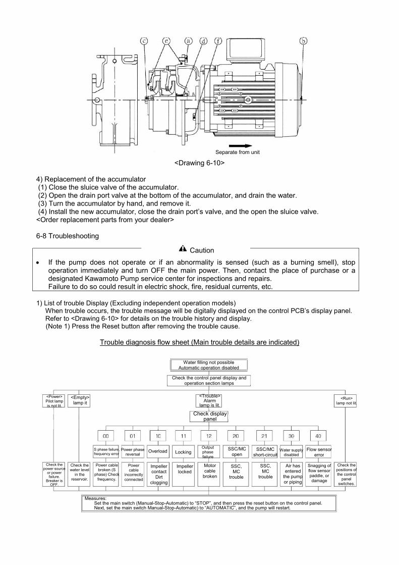
<Drawing 6-10>
4) Replacement of the accumulator (1) Close the sluice valve of the accumulator. (2) Open the drain port valve at the bottom of the accumulator, and drain the water. (3) Turn the accumulator by hand, and remove it. (4) Install the new accumulator, close the drain port’s valve, and the open the sluice valve. <Order replacement parts from your dealer> 6-8 Troubleshooting
Caution
If the pump does not operate or if an abnormality is sensed (such as a burning smell), stop
operation immediately and turn OFF the main power. Then, contact the place of purchase or a designated Kawamoto Pump service center for inspections and repairs. Failure to do so could result in electric shock, fire, residual currents, etc.
1) List of trouble Display (Excluding independent operation models)
When trouble occurs, the trouble message will be digitally displayed on the control PCB’s display panel. Refer to <Drawing 6-10> for details on the trouble history and display. (Note 1) Press the Reset button after removing the trouble cause.
Trouble diagnosis flow sheet (Main trouble details are indicated)
Separate from unit
Water filling not possible Automatic operation disabled
Check the control panel display and operation section lamps
<Power> Pilot lamp is not lit.
<Empty> lamp it
<Trouble> Alarm
lamp is lit. Check display
panel
<Run> lamp not lit.
S phase failure, frequency error
Power phase reversal Overload Locking
Output phase failure
SSC/MC open
SSC/MC short-circuit Water supply
disabled Flow sensor
error
Check the power source
or power failure.
Breaker is OFF.
Check the water level
in the reservoir.
Check the positions of the control
panel switches.
Measures: Set the main switch (Manual-Stop-Automatic) to “STOP”, and then press the reset button on the control panel. Next, set the main switch Manual-Stop-Automatic) to “AUTOMATIC”, and the pump will restart.
Power cable broken (S
phase) Check frequency.
Power cable
incorrectly connected
Impeller contact
Dirt clogging
Impeller locked
Motor cable
broken
SSC, MC
trouble
SSC, MC
trouble
Air has entered
the pump or piping
Snagging of flow sensor paddle, or damage

*1.The flow sensor is designed so that the pump will stop when the sensor is disconnected from the connector. 2) Troubleshooting Table.
Phenomenon Cause Measure
The power source pilot lamp does not light
The residual current circuit break is tripped.
Turn the residual current circuit breaker ON.
Power cable R or T phase failure. Connect the power cable R or T phase.
The motor rotates, but the water is not discharged. The water is discharged but the pressure does not rise.
Reservoir is empty (during manual operation)
Fill the reservoir with water.
The sluice valve is closed or half-opened
Open the sluice value
The pump rotation direction is reversed.
Correctly connect
The pump is not filled with water Sufficiently prime the pump The pump does not separate. The pump operates even when water is not being used.
The main switch is set to “Manual”
Set the main switch to “Automatic”
Water is leaking from the pipes Inspect and repair
Alternate operation is not possible.
The main switch is set to “Manual”
Set the main switch to “Automatic”
The select switch is set to “1” or “2”
Set the select switch “1” or “2”
Parallel operation is not possible.
The main switch is set to “Manual”
Set the main switch to “Automatic”
The select switch is set to “1” or “2”
Set the select switch “1” or “2”
The pressure sensor pressure setting is too low
Adjust the set pressure
The stop time is short
The accumulator sluice valve is closed
Open the sluice valve
The accumulator sealed gas pressure has dropped.
Replenish the air
The accumulator is damaged Replace the accumulator A mechanical sound may be heard when the pump starts or stops, but this is not an error. Unexpected trouble could occur. However, it is important to take appropriate measures immediately when an abnormal condition is found. If the cause of the trouble is not clear, contact your dealer or designated service center. Notice the pump type, serial No. and trouble (fault) state making an inquiry.
Automatic operation disabled
Remedy for sensor fault, etc.
Restarting disabled Stopping disabled Starting pressure is low or high
Stop time is short Intermittent operation repeated
Pressure sensor insertion fault, part fault, or ball valve
closed.
Flow sensor part fault (Paddle snagging)
Pressure sensor adjustment fault or
part fault
Accumulator sealed pressure low, or
damaged
Flow sensor insertion fault, or part fault.
Check pressure sensor. Replace with new part,
or open ball valve
Remove flow sensor on operation side, and
check operation
Readjust pressure sensor or replace
with new part
Fill accumulator with air, or replace with new part
Check flow sensor operation, or replace
with new part

7. Examples of theseal drawing ・Unit
Pump
・Booster pump parts list
No. Name Material No. Name Material
003 Pump - 374-1 Plain washer SUS304
012 Accumulator - 374-2 Spring washer SUS304
023 Flexible Joint SUS304 394 Band Resin
032 Check valve SCS13 397-1 Clamp Resin
038 Exhaust valve (C3604) 397-2 Clamp Resin
039-1 Ball valve (C3604BD) 404 Base SPHC
039-2 Ball valve (C3771BE) 420 Lid Resin
077 Control panel Outdoor 460-1 Cushion Rubber
263 Connecting bend SCS13 460-2 Cushion Steel + Rubber
269 Connecting pipe SCS13 491 Ring SUS304
270 Flange SCS13 602 Code (VCTF)
281 Cheese SCS13 613-1 Marker tube POM
287 Plug SCS13 613-2 Marker tube POM
304 O-ring Rubber 615 Code bush Rubber (NR)
307 Ring packing Rubber (EPDM) 694-1 Flow sensor -
310 Flange packing Rubber (EPDM) 694-2 Pressure sensor -
312 Square flange packing Rubber (EPDM) 700 Pressure gauge -
364 Bolt SUS304 713-1 Indication label A1100P-H24
370 Nut SUS304 854 Nameplate A1100P-H24


・Main pump
・Main pump parts list
No. Name Material No. Name Material
056 Motor - 173 Partition plate SUS304
104 Casing SCS13 300 Mechanical seal Sic x Carbon
122 Casing cover SCS13 304 O-ring Rubber (NBR)
135 Impeller SCS13, Resin CAC406(BC6)
364-1 Bolt SUS304 364-2 Double end stud bolt SUS304
160 Sleeve Bronze or SUS304 370 Nut SUS304 166 Deflector Rubber (NBR) 374 Plain washer SUS304
171-1 Guide vane Resin or Bronze 419 Protection cap Rubber
171-2 Guide vane Resin or Bronze 464 Spring receiver SUS304

8. Control panel circuit diagram