16623 mil-dtl-5015, matrix - amphenol aerospace corporation 40-60 delaware avenue, sidney, ny...
TRANSCRIPT

AMPHENOL CORPORATION
40-60 Delaware Avenue, Sidney, NY 13838-1395 • 800-678-0141 • www.amphenol-aerospace.com
16623
MIL-DTL-5015, MatrixCRIMP REAR RELEASE SERIES
1Contact Amphenol Aerospace for more information at 800-678-0141 • www.amphenol-aerospace.com
MIL-DTL-5015, Matrix®
TABLE OF CONTENTS FOR SECTION MMIL-DTL-5015, Matrix®Design Characteristics, Customer Options . . . . . . . . . . . . . . . . . . . . . . . . . . . . . . . . . . . .2Insert Availability and Identification . . . . . . . . . . . . . . . . . . . . . . . . . . . . . . . . . . . . . . . . . .3, 4Insert Arrangement Drawings . . . . . . . . . . . . . . . . . . . . . . . . . . . . . . . . . . . . . . . . . . . . . .5-13Class Descriptions, Performance Specifications . . . . . . . . . . . . . . . . . . . . . . . . . . . . . . . .14Insert Alternate Positioning . . . . . . . . . . . . . . . . . . . . . . . . . . . . . . . . . . . . . . . . . . . . . . . .15How to Order, Military and Commercial . . . . . . . . . . . . . . . . . . . . . . . . . . . . . . . . . . . . . . .16
Shell Styles:Wall mounting receptacle threaded MS3450 (9440) . . . . . . . . . . . . . . . . . . . . . . . . . . . . .17Cable connecting receptacle threaded MS3451 (9441) . . . . . . . . . . . . . . . . . . . . . . . . . . .18Box mounting receptacle threaded MS3452 (9442) . . . . . . . . . . . . . . . . . . . . . . . . . . . . . .19Jam nut receptacle threaded MS3454 (9444) . . . . . . . . . . . . . . . . . . . . . . . . . . . . . . . . . .20Straight plug threaded MS3456 (9446) . . . . . . . . . . . . . . . . . . . . . . . . . . . . . . . . . . . . . . .21Straight plug, self-locking threaded MS3459 (9816) . . . . . . . . . . . . . . . . . . . . . . . . . . . . .22Quick disconnect plug push-pull coupling (9817/9818) . . . . . . . . . . . . . . . . . . . . . . . . . . .23Matrix® 5015 with RADSOK® contacts, for high power . . . . . . . . . . . . . . . . . . . . . . . . . .24Contact information, sealing plugs, tools . . . . . . . . . . . . . . . . . . . . . . . . . . . . . . . . . . . . .25Protection caps, dust caps . . . . . . . . . . . . . . . . . . . . . . . . . . . . . . . . . . . . . . . . . . . . . . . .26-28Additional MIL-DTL-5015 connectors offered by Amphenol . . . . . . . . . . . . . . . . . . . . . . .29
M
Contact Amphenol Aerospace for more information at 800-678-0141 • www.amphenol-aerospace.com
50
15
MA
TR
IX
M2
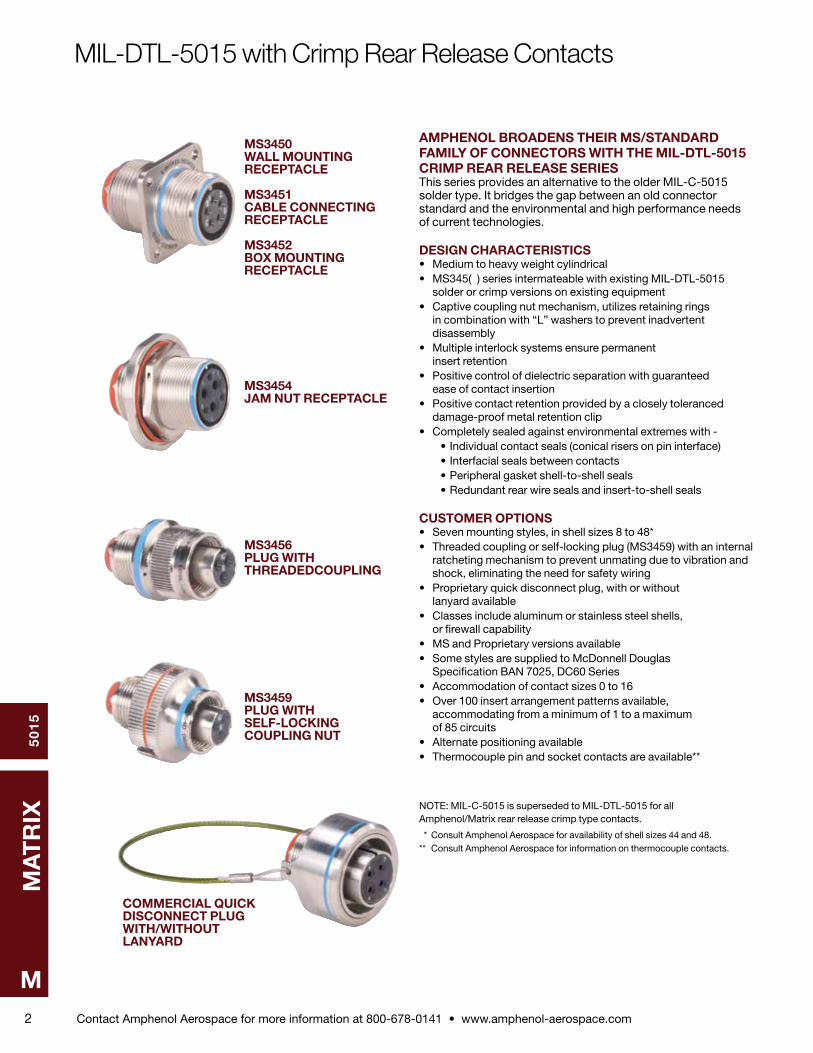
MS3450 WALL MOUNTING RECEPTACLE
MS3451 CABLE CONNECTING RECEPTACLE
MS3452 BOX MOUNTING RECEPTACLE
MS3454 JAM NUT RECEPTACLE
MS3456 PLUG WITH THREADEDCOUPLING
MS3459 PLUG WITH SELF-LOCKING COUPLING NUT
AMPHENOL BROADENS THEIR MS/STANDARD FAMILY OF CONNEC TORS WITH THE MIL-DTL-5015 CRIMP REAR RELEASE SERIESThis series provides an alternative to the older MIL-C-5015 solder type . It bridges the gap between an old connector stan dard and the environmental and high performance needs of current technologies .
DESIGN CHARACTERISTICS• Medium to heavy weight cylindrical• MS345( ) series intermateable with existing MIL-DTL-5015 solder or crimp versions on existing equipment• Captive coupling nut mechanism, utilizes retaining rings in combination with “L” washers to prevent inadvertent disas sembly• Multiple interlock systems ensure permanent insert reten tion• Positive control of dielectric separation with guaranteed ease of contact insertion• Positive contact retention provided by a closely toleranced damage-proof metal retention clip• Completely sealed against environmental extremes with - • Individual contact seals (conical risers on pin interface) • Interfacial seals between contacts • Peripheral gasket shell-to-shell seals • Redundant rear wire seals and insert-to-shell seals
CUSTOMER OPTIONS• Seven mounting styles, in shell sizes 8 to 48*• Threaded coupling or self-locking plug (MS3459) with an internal ratcheting mechanism to prevent unmating due to vibration and shock, eliminating the need for safety wiring• Proprietary quick disconnect plug, with or without lanyard available• Classes include aluminum or stainless steel shells, or firewall capability• MS and Proprietary versions available• Some styles are supplied to McDonnell Douglas Specifica tion BAN 7025, DC60 Series• Accommodation of contact sizes 0 to 16• Over 100 insert arrangement patterns available, accom modating from a minimum of 1 to a maximum of 85 circuits• Alternate positioning available• Thermocouple pin and socket contacts are available**
NOTE: MIL-C-5015 is superseded to MIL-DTL-5015 for all Amphenol/Matrix rear release crimp type contacts .
* Consult Amphenol Aerospace for availability of shell sizes 44 and 48 .** Consult Amphenol Aerospace for information on thermocouple contacts .
MIL-DTL-5015 with Crimp Rear Release Contacts
COMMERCIAL QUICK DISCONNECT PLUG WITH/WITHOUT LANYARD

Contact Amphenol Aerospace for more information at 800-678-0141 • www.amphenol-aerospace.com
50
15
MA
TR
IX
M3
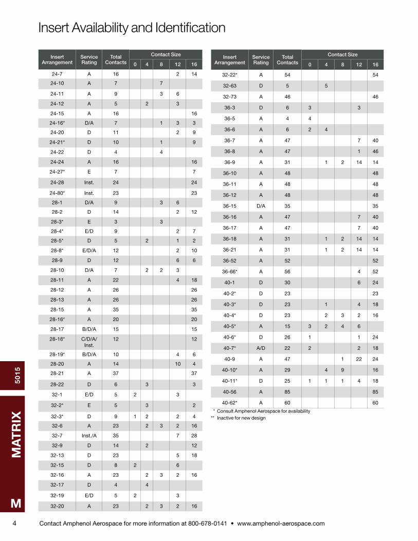
Insert Availability and Identification
Insert Arrangement
Service Rating
Total Contacts
Contact Size
0 4 8 12 16
8S-1 A 1 1
10S-2 A 1 1
10SL-3 A 3 3
10SL-4 A 2 2
12S-1 A 2 2
12S-2 A 2 2
12S-3 A 2 2
12S-4 D 1 1
12-5 D 1 1
14S-1** A 3 3
14S-2 Inst . 4 4
14-3 A 1 1
14S-5 Inst . 5 5
14S-6 Inst . 6 6
14S-7 A 3 3
14S-9** A 2 2
14S-10 Inst . 4 4
14S-11 Inst . 4 4
14S-12 A 3 3
14S-13 A 3 3
16S-1 A 7 7
16-2* E 1 1
16S-3* B 1 1
16S-4* D 2 2
16-7* A 3 1 2
16S-8 A 5 5
16-9 A 4 2 2
16-10 A 3 3
16-11 A 2 2
16-12 A 1 1
16-13 A 2 2
18-1 A/Inst . 10 10
18-4 D 4 4
18-5 • D 3 2 1
18-6* D 1 1
18-7* B 1 1
18-8 A 8 1 7
18-9 Inst . 7 2 5
18-10** A 4 4
18-11 A 5 5
18-12 A 6 6
18-13 A 4 1 3
18-14* A 2 1 1
18-15 A 4 4
18-16* C 1 1
18-17 Inst . 7 2 5
18-18 Inst . 7 2 5
18-19** A 10 10
18-22** D 3 3
18-23 A/Inst . 10 10
Insert Arrangement
Service Rating
Total Contacts
Contact Size
0 4 8 12 16
18-24 A/Inst . 10 10
18-27• D 3 2 1
18-28• D 3 2 1
20-2 D 1 1
20-4 D 4 4
20-7 D/A 8 8
20-8 Inst . 6 2 4
20-9* D/A 8 1 7
20-14 A 5 2 3
20-15 A 7 7
20-16 A 9 2 7
20-17 A 6 5 1
20-18 A 9 3 6
20-19 A 3 3
20-21 A 9 1 8
20-22 A 6 3 3
20-24 A 4 2 2
20-27 A 14 14
20-29 A 17 17
20-32 D/A 8 8
20-33 A 11 11
22-2 D 3 3
22-4** A 4 2 2
22-5 D 6 2 4
22-6* D 3 2 1
22-7* E 1 1
22-9* E 3 3
22-10* E 4 4
22-11* B 2 2
22-12* D 5 2 3
22-14 A 19 19
22-15* E/A 6 5 1
22-17* D/A 9 1 8
22-18* D/A 8 8
22-19 A 14 14
22-21 A 3 1 2
22-22 A 4 4
22-23 D/A 8 8
22-27* D/A 9 1 8
22-30 A 19 19
22-32 D 6 2 4
22-36* D/A 8 8
24-1** D 2 1 1
24-2 D 7 7
24-4* D 4 1 3
24-5** A 16 16
24-6* D/A 8 8 * Consult Amphenol Aerospace for availability** Inactive for new design• Socket Only
Contact Amphenol Aerospace for more information at 800-678-0141 • www.amphenol-aerospace.com
50
15
MA
TR
IX
M4
Insert Availability and Identification
Insert Arrangement
Service Rating
Total Contacts
Contact Size
0 4 8 12 16
24-7 A 16 2 14
24-10 A 7 7
24-11 A 9 3 6
24-12 A 5 2 3
24-15 A 16 16
24-16* D/A 7 1 3 3
24-20 D 11 2 9
24-21* D 10 1 9
24-22 D 4 4
24-24 A 16 16
24-27* E 7 7
24-28 Inst . 24 24
24-80* Inst . 23 23
28-1 D/A 9 3 6
28-2 D 14 2 12
28-3* E 3 3
28-4* E/D 9 2 7
28-5* D 5 2 1 2
28-8* E/D/A 12 2 10
28-9 D 12 6 6
28-10 D/A 7 2 2 3
28-11 A 22 4 18
28-12 A 26 26
28-13 A 26 26
28-15 A 35 35
28-16* A 20 20
28-17 B/D/A 15 15
28-18* C/D/A/Inst .
12 12
28-19* B/D/A 10 4 6
28-20 A 14 10 4
28-21 A 37 37
28-22 D 6 3 3
32-1 E/D 5 2 3
32-2* E 5 3 2
32-3* D 9 1 2 2 4
32-6 A 23 2 3 2 16
32-7 Inst ./A 35 7 28
32-9 D 14 2 12
32-13 D 23 5 18
32-15 D 8 2 6
32-16 A 23 2 3 2 16
32-17 D 4 4
32-19 E/D 5 2 3
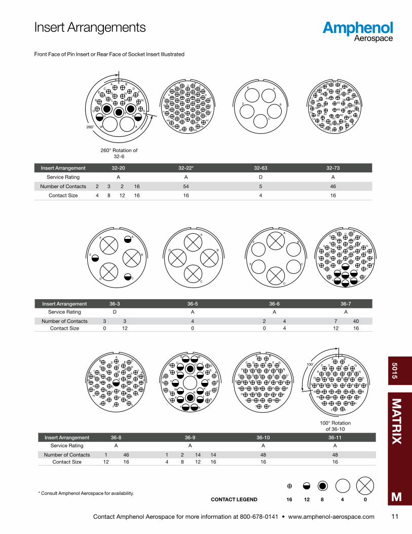
32-20 A 23 2 3 2 16
Insert Arrangement
Service Rating
Total Contacts
Contact Size
0 4 8 12 16
32-22* A 54 54
32-63 D 5 5
32-73 A 46 46
36-3 D 6 3 3
36-5 A 4 4
36-6 A 6 2 4
36-7 A 47 7 40
36-8 A 47 1 46
36-9 A 31 1 2 14 14
36-10 A 48 48
36-11 A 48 48
36-12 A 48 48
36-15 D/A 35 35
36-16 A 47 7 40
36-17 A 47 7 40
36-18 A 31 1 2 14 14
36-21 A 31 1 2 14 14
36-52 A 52 52
36-66* A 56 4 52
40-1 D 30 6 24
40-2* D 23 23
40-3* D 23 1 4 18
40-4* D 23 2 3 2 16
40-5* A 15 3 2 4 6
40-6* D 26 1 1 24
40-7* A/D 22 2 2 18
40-9 A 47 1 22 24
40-10* A 29 4 9 16
40-11* D 25 1 1 1 4 18
40-56 A 85 85
40-62* A 60 60
* Consult Amphenol Aerospace for availability** Inactive for new design
Contact Amphenol Aerospace for more information at 800-678-0141 • www.amphenol-aerospace.com
50
15
MA
TR
IX
M5
BA B A
A
BC
DA
B
C
D
E F A
B
CD
E
AB
100˚A
BC
D
100˚
A
B
C
A
B
CD
E
F
G
AB
A B
C
A
BC
D
E
100° Rotation of 12S-3
250° Rotation of 12S-3
100° Rotation of 14S-2
250° Rotation of 14S-2
100° Rotation of 14S-1
260° Rotation of 14S-1
C
BA
B A100˚
B A
250˚
A
B
C
250˚
A
BC
D
260˚
A
B
C
A
B
C
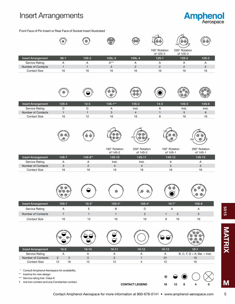
Insert Arrangement 8S-1 10S-2 10SL-3 10SL-4 12S-1 12S-2 12S-3
Service Rating A A A*** A A A ANumber of Contacts 1 1 3 2 2 2 2
Contact Size 16 16 16 16 16 16 16
Insert Arrangement 12S-4 12-5 14S-1** 14S-2 14-3 14S-5 14S-6
Service Rating D D A Inst . A Inst . Inst .Number of Contacts 1 1 3 4 1 5 6
Contact Size 16 12 16 16 8 16 16
Insert Arrangement 14S-7 14S-9** 14S-10 14S-11 14S-12 14S-13
Service Rating A A Inst . Inst . A ANumber of Contacts 3 2 4 4 3 3
Contact Size 16 16 16 16 16 16
Insert Arrangement 16S-1 16-2* 16S-3* 16S-4* 16-7* 16S-8
Service Rating A E B D A A
Number of Contacts 7 1 1 2 1 2 5
Contact Size 16 12 16 16 8 16 16
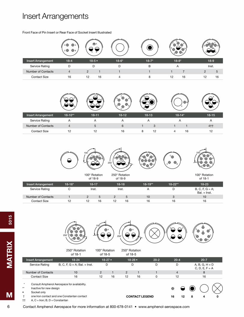
Front Face of Pin Insert or Rear Face of Socket Insert Illustrated
* Consult Amphenol Aerospace for availability .** Inactive for new design*** Service rating Inst . Class K† one Iron contact and one Constantan contact
A
B
C
D
B
C A A
B
AB
A
B
C
DE
F
G
H
I
J
Insert Arrangement 16-9 16-10 16-11 16-12 16-13 18-1
Service Rating A A A A A B, C, F, G = A; Bal . = Inst .Number of Contacts 2 2 3 2 1 2† 10
Contact Size 12 16 12 12 4 12 16
Insert Arrangements
CONTACT LEGEND 16 12 8 4 0
Contact Amphenol Aerospace for more information at 800-678-0141 • www.amphenol-aerospace.com
50
15
MA
TR
IX
M6
A
BC
DA
BC
A
B
CD
E
FG
H
A
B
C
D
E
F
G
A
BC
DA
BC
D
E
A
B
C
D
EF
A
B
C
D
A
B
A
B
C
D
100˚
A
B
C
D
E
F
G
A
B CD E F G
H
K
J A B
C
* Consult Amphenol Aerospace for availability .** Inactive for new design• Socket only † one Iron contact and one Constantan contact†† A, C = Iron; B, D = Constantan
100° Rotation of 18-9
250° Rotation of 18-9
100° Rotation of 18-1
A
B
C
DE
F
G
H
I
J
100˚
250˚A
B
C
D
E
F
G
Insert Arrangement 18-4 18-5 • 18-6* 18-7* 18-8* 18-9
Service Rating D D D B A Inst .
Number of Contacts 4 2 1 1 1 1 7 2 5
Contact Size 16 12 16 4 8 12 16 12 16
Insert Arrangement 18-10** 18-11 18-12 18-13 18-14* 18-15
Service Rating A A A A A A
Number of Contacts 4 5 6 1 3 1 1 4††
Contact Size 12 12 16 8 12 4 16 12
Insert Arrangement 18-16* 18-17 18-18 18-19** 18-22** 18-23
Service Rating C Inst . Inst . A D B, C, F, G = A; Bal . = Inst .
Number of Contacts 1 2 5 2 5 10 3 10Contact Size 12 12 16 12 16 16 16 16
Front Face of Pin Insert or Rear Face of Socket Insert Illustrated
250˚
A
B
C
DE
F
G
H
I
J
A
B
D
C
A
B
C
DE
F
GH
250° Rotation of 18-1
100° Rotation of 18-5
250° Rotation of 18-5
A
BC
100˚
A
BC250˚
Insert Arrangement 18-24 18-27 • 18-28 • 20-2 20-4 20-7
Service Rating B, C, F, G = A; Bal . = Inst . D D D D A, B, G, H = D C, D, E, F = A
Number of Contacts 10 2 1 2 1 1 4 8Contact Size 16 12 16 12 16 0 12 16
Insert Arrangements
CONTACT LEGEND 16 12 8 4 0
Contact Amphenol Aerospace for more information at 800-678-0141 • www.amphenol-aerospace.com
50
15
MA
TR
IX
M7
A
B
C
D
E F
A
B
C
DE
F
G H A
B
C
D
E A
B
CD
E G
F
AB
C
D
EF
G
HI
A
BC
D
E
F
A
B
C
D
E
F
GH
I
A
BC
A
B
C
DE
F
G
H
I A
B
C
D
E
F A
B
C
D
AB
CD
EF
G
H
IJ
K
L
M
N
*Consult Amphenol Aerospace for availability .
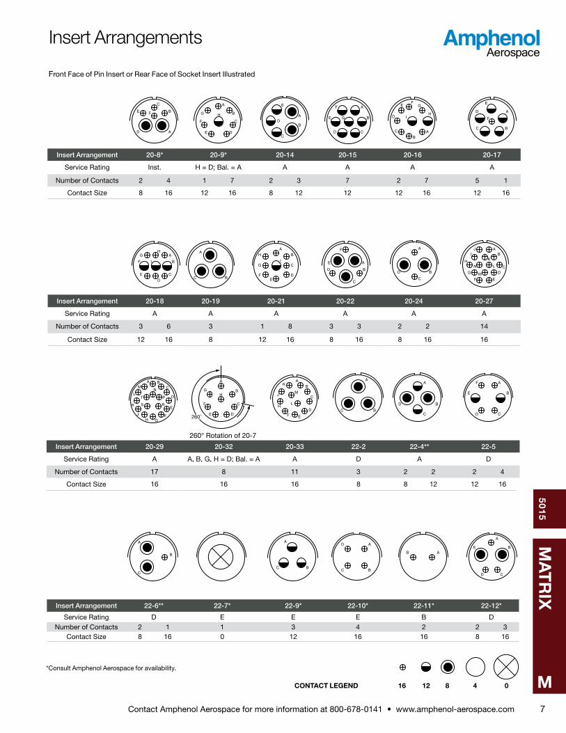
Insert Arrangement 20-8* 20-9* 20-14 20-15 20-16 20-17
Service Rating Inst . H = D; Bal . = A A A A A
Number of Contacts 2 4 1 7 2 3 7 2 7 5 1
Contact Size 8 16 12 16 8 12 12 12 16 12 16
Insert Arrangement 20-18 20-19 20-21 20-22 20-24 20-27
Service Rating A A A A A A
Number of Contacts 3 6 3 1 8 3 3 2 2 14
Contact Size 12 16 8 12 16 8 16 8 16 16
Front Face of Pin Insert or Rear Face of Socket Insert Illustrated
A BC
D
E
FGH
J
K
L
MN
PT
S R
AB
C
D
EF
K
H
JM
L
A
BC
A
B
C
D
A
B
CD
E
F
260° Rotation of 20-7
A
B
C
DE
F
GH
260˚
Insert Arrangement 20-29 20-32 20-33 22-2 22-4** 22-5
Service Rating A A, B, G, H = D; Bal . = A A D A D
Number of Contacts 17 8 11 3 2 2 2 4
Contact Size 16 16 16 8 8 12 12 16
A
B
C
A
BC
A
BC
D
AB
A
B
CD
E
Insert Arrangement 22-6** 22-7* 22-9* 22-10* 22-11* 22-12*
Service Rating D E E E B DNumber of Contacts 2 1 1 3 4 2 2 3
Contact Size 8 16 0 12 16 16 8 16
Insert Arrangements
CONTACT LEGEND 16 12 8 4 0
Contact Amphenol Aerospace for more information at 800-678-0141 • www.amphenol-aerospace.com
50
15
MA
TR
IX
M8
A
B
C
D
EF
G
H
J
K
L M
NU
V
RS
T P
A
B
E
F
CD
AB
C
D
E
F
G
H
J
A
B
C
D
E
F
G
H
AB
C
D
EF
G
H
J
KL
M
N
P
A
B
C
*Consult Amphenol Aerospace for availability .** Inactive for new design
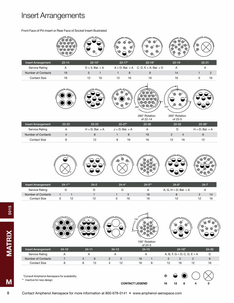
Insert Arrangement 22-14 22-15* 22-17* 22-18* 22-19 22-21
Service Rating A D = 3; Bal . = A A = D; Bal . = A C, D, E = A: Bal . = D A A
Number of Contacts 19 5 1 1 8 8 14 1 2
Contact Size 16 12 16 12 16 16 16 0 16
Front Face of Pin Insert or Rear Face of Socket Insert Illustrated
A
BC
DA
B
CD
E
FG
H
AB
C
D
E
F
G
H
J
AB
C
D
E
F
G
H
A
B
CD
E
F
G
A BC
D EF G H
J KL M N
PS
R
AB
C
D
E
F
G
H
AB
C
D
E
FG
H
J
KL
M
NP
I O
A
B
CD
E
FG
A B C
D E F
G
H
I
A
B
C
D
E
260° Rotation of 22-5
A
B
C
DE
FG
H
J
K
L M
NU
V
RS
T P
260˚
A
B
CD
E
F
260˚
A
B
B
C
D
A
Insert Arrangement 22-22 22-23 22-27* 22-30 22-32 22-36*
Service Rating A H = D; Bal . = A J = D; Bal . = A A D H = D; Bal . = A
Number of Contacts 4 8 1 8 19 2 4 8
Contact Size 8 12 8 16 16 12 16 12
260° Rotation of 22-14
Insert Arrangement 24-1** 24-2 24-4* 24-5** 24-6* 24-7
Service Rating D D D A A, G, H = D; Bal . = A A
Number of Contacts 1 1 7 1 3 16 8 2 14Contact Size 0 12 12 0 16 16 12 12 16
Insert Arrangement 24-10 24-11 24-12 24-15 24-16* 24-20
Service Rating A A A A A, B, F, G = D; C, D, E = A D
Number of Contacts 7 3 6 2 3 16 1 3 3 2 9
Contact Size 8 8 12 4 12 16 8 12 16 12 16
A
B
C
D
E
FG
AB
C
D
EF
G
H
J
K L
100° Rotation of 24-5
A BC
D EF G H
J KL M N
PS
R
100˚
Insert Arrangements
CONTACT LEGEND 16 12 8 4 0
Contact Amphenol Aerospace for more information at 800-678-0141 • www.amphenol-aerospace.com
50
15
MA
TR
IX
M9
AB
C
D
E
F
G
H
J K
A
BC
DA
B
C
D
E
F
G
A B C D
E F G H J
K L M N P Q
R S T U V
W X Y Z
A B
C
DEF
G
H
J
A
B
C
D
EF
G
H
J
K
L
M
N
P
A
BC
A B
C DP
S
E FG
A
B
CD
E
A
B
C
D
E
F
G
H
J
K
L
M
250° Rotation of 24-5
* Consult Amphenol Aerospace for availability .
A BC
D EF G H
J KL M N
PS
R
250˚
A B C D
E F G H
K L M N P Q
R S T U V
W X Z
J
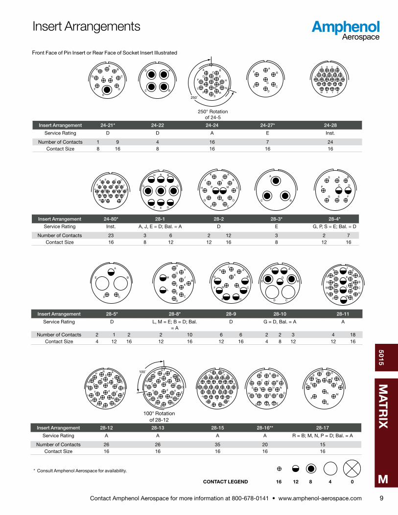
Insert Arrangement 24-21* 24-22 24-24 24-27* 24-28
Service Rating D D A E Inst .
Number of Contacts 1 9 4 16 7 24Contact Size 8 16 8 16 16 16
Insert Arrangement 24-80* 28-1 28-2 28-3* 28-4*
Service Rating Inst . A, J, E = D; Bal . = A D E G, P, S = E; Bal . = D
Number of Contacts 23 3 6 2 12 3 2 7Contact Size 16 8 12 12 16 8 12 16
Insert Arrangement 28-5* 28-8* 28-9 28-10 28-11
Service Rating D L, M = E; B = D; Bal . = A
D G = D, Bal . = A A
Number of Contacts 2 1 2 2 10 6 6 2 2 3 4 18Contact Size 4 12 16 12 16 12 16 4 8 12 12 16
Front Face of Pin Insert or Rear Face of Socket Insert Illustrated
A
B
C
DE
F
G
HJ
K
LM
A
B
CD
E
F
G A
B
C
D
E
F
G
H
J
K
L
MI
N
P
R
S
T
U
V
W
X
A
B
C
D
E
F
GH
JK
L
M
PR
N
ST
U
V
WX
Y
Z
a
b
d
100˚ A
B
C
D
E
F
GH
JK
L
M
PR
N
ST
U
V
WX
Y
Z
a
b
d
A BC D E F G
H J K L M
P R S T
N
W
X Y Z
U V
a b c
de
f
gh
j k
ml
AB
C
D
EFG
H
J
K
L M
PQR
S
T
UV NA
B
CD
E
FG
H J K
L
M
N
P
R
100° Rotation of 28-12
Insert Arrangement 28-12 28-13 28-15 28-16** 28-17
Service Rating A A A A R = B; M, N, P = D; Bal . = A
Number of Contacts 26 26 35 20 15Contact Size 16 16 16 16 16
Insert Arrangements
CONTACT LEGEND 16 12 8 4 0

Contact Amphenol Aerospace for more information at 800-678-0141 • www.amphenol-aerospace.com
50
15
MA
TR
IX
M10
AB
C
D
E
FG
H
J
K
L
M
A B
C
E
GH
J
K
L
M
A
B
C
D
EF
G
H
J
K
LM
NP
AB C
DE F G H J
K L M N P R
S T U V W X Z
a b c d e f
gh
jk m
n p r s
* Consult Amphenol Aerospace for availability .** Inactive for new design
Insert Arrangement 28-18* 28-19* 28-20 28-21
Service Rating M = C; G, H, J, K, L = D; A, B = A; Bal . = Inst . H, M = B; A, B = D; Bal . = A A ANumber of Contacts 12 4 6 10 4 37
Contact Size 16 12 16 12 16 16
Front Face of Pin Insert or Rear Face of Socket Insert Illustrated
A
B
C
DE
F
A
B
CD
E
A
B
C
D
E
AB
C
D E F
G
H
J
A B
C DE FG H
JK L M N
O
P R
ST
U V
W
I
X
A
B
C
D
E
F
G
H
I
J
K
L
M
N
O
P
R
S
T
U
V
W
X
Y
Z
a
b
c
d
e
f
g
h
j
k
A B
C D E F G
H I J K
L M N
A
B
C
D
E
F
G
H
J
K
L
M
N
PR
S
T
U
V
W
XY
Z
A
B C
D E
F
G
H
100˚A B
C D
E FG H
I J
K L M N
O
P R
ST
U V
W X
A
BC
D
100° Rotation of 32-6
260° Rotation of 32-1
CD
E
260˚
B
A
Insert Arrangement 28-22 32-1 32-2* 32-3* 32-6
Service Rating D A = E; B, C, D, E = D E D A
Number of Contacts 3 3 2 3 3 2 1 2 2 4 2 3 2 16Contact Size 4 16 0 12 4 16 0 4 12 16 4 8 12 16
Insert Arrangement 32-7 32-9 32-13 32-15
Service Rating A, B, h, j = Inst .; Bal . = A D D D
Number of Contacts 7 28 2 12 5 18 2 6Contact Size 12 16 4 16 12 16 0 12
Insert Arrangement 32-16 32-17 32-19
Service Rating A D A = E, Bal . = D
Number of Contacts 2 3 2 16 4 2 3Contact Size 4 8 12 16 4 0 12
Insert Arrangements
CONTACT LEGEND 16 12 8 4 0
Contact Amphenol Aerospace for more information at 800-678-0141 • www.amphenol-aerospace.com
50
15
MA
TR
IX
M11
A BC D E
F G H J
K L MN O P R
S T U V WX Y Z a
b c d e f
g h j km n p r
tq
s u vx y
z AAAB AC
AD AE
AF AG
w
12
3
4
5
6
7
8
91011
12
13
14
15
16
17
18
1920 21
22
23
24
25
26
27
282930
31
32
33
34
35
36
37
38
39
4041
42
43
44
45
46
A
B
CD
E
FA
B
C
D
A
B
C
D
E
F
A B
CD
E
F GH I J
K L M NO P R S T
U V W X
Y Z a b c
d e f gh j k m
n p
r
t
s
u v
x y
z
w
AB C
D EFG H
I J K LMN
O P RS
T UV
WX
YZ
a
b c d e
f g h jk
mn p r
tuv w
s
x yz
A
B
C
D
E
F
G
H
I
J
K
L
M
N
O
P
R
S
T
U
V
W
X
Y
Z
a
b
c
d
e
f
A B
C D E F G
H J K L M N
O P Q R S T U
V W X Y Z a b c
d e f g h j k
m n p r
t u v w
s
x
y z
q
100˚
A B
C D E F G
H J K L M N
O P Q R S T U
V W X Y Z a b c
d e f g h j k
m n p r
t u v w
s
x
y z
q
260° Rotation of 32-6
* Consult Amphenol Aerospace for availability .
100° Rotation of 36-10
A B
C DE FG H
JK L M N
O
P R
ST
U V
W
I
X260˚
A
B
C
D
E
Insert Arrangement 32-20 32-22* 32-63 32-73
Service Rating A A D A
Number of Contacts 2 3 2 16 54 5 46
Contact Size 4 8 12 16 16 4 16
Insert Arrangement 36-3 36-5 36-6 36-7
Service Rating D A A A
Number of Contacts 3 3 4 2 4 7 40Contact Size 0 12 0 0 4 12 16
Insert Arrangement 36-8 36-9 36-10 36-11
Service Rating A A A A
Number of Contacts 1 46 1 2 14 14 48 48Contact Size 12 16 4 8 12 16 16 16
Front Face of Pin Insert or Rear Face of Socket Insert Illustrated
Insert Arrangements
CONTACT LEGEND 16 12 8 4 0

Contact Amphenol Aerospace for more information at 800-678-0141 • www.amphenol-aerospace.com
50
15
MA
TR
IX
M12
110˚
A B
C D E F G
H J K L M N
O P Q R S T U
V W X Y Z a b c
d e f g h j k
m n p r
t u v w
s
x
y z
q
A
B
C
D
E
F
G
HJ
K
L
M
N
P
Q
R
S
TU
V
W
X
YZ
a
b
c
d
e
f
gh
j
k
m
100˚A B
C D EF G
H I JK
L MN
OP R S
T
U V W XY Z a b c
d e f g
h j kmn p
r
t
u vw
s
x y
z
110˚
A B
CD
EF G
H I JK L M N
O P R ST
U V W XY Z a b c
d ef g
h j km
n p
r
tu v
ws
x y
z
100˚
A
B
C
D
E
F
G
H
I
J
K
L
M
N
O
P
R
S
T
U
V
W
X
Y
Z
a
b
c
d
e
f
A B C D
E F H J K
L M N P R S
T U V W X Y Z
a b c d f g h i
j k m n p r
t u v ws x
y z
q
AA ABAC
AD
AE AF
AH
A B C
D E F G
H I J K L
M N O P R S
T U V W X
Y Z a b
c d e
110° Rotation of 36-10
100° Rotation of 36-7
* Consult Amphenol Aerospace for availability .
110° Rotation of 36-7
100° Rotation of 36-9
260° Rotation of 36-9
A
B
C
D
E
F
G
H
I
J
K
L
M
N
O
P
R
S
T
U
V
W
X
Y
Z
a
b
c
d
e
f
260˚
ABC
DEFGHJ
LMNPRS
TUVWXYZa
bcdefghj
klmnprt
uvw
s
xyzAA
ABACADAEAF
AKAJ
AH
AG
K
A
B
C
D
E
F
G
H
J
K
L
M
N
O
P
R
S
T
U
V
W
X
Z
A B
C D E F G
H J K L M N
O P R S T
U V W X
Y
Insert Arrangement 36-12 36-15 36-16 36-17
Service Rating A M = D, Bal . = A A A
Number of Contacts 48 35 7 40 7 40
Contact Size 16 16 12 16 12 16
Front Face of Pin Insert or Rear Face of Socket Insert Illustrated
Insert Arrangement 36-18 36-21 36-52 36-66*
Service Rating A A A A
Number of Contacts 1 2 14 14 1 2 14 14 52 4 52
Contact Size 4 8 12 16 4 8 12 16 16 12 16
Insert Arrangement 40-1 40-2* 40-3*
Service Rating D D D
Number of Contacts 6 24 23 1 4 18
Contact Size 12 16 16 4 12 16
Insert Arrangements
CONTACT LEGEND 16 12 8 4 0

Contact Amphenol Aerospace for more information at 800-678-0141 • www.amphenol-aerospace.com
50
15
MA
TR
IX
M13
A BC
D EF
G HI J K L
M N O P Q R S T
U V W X Y Z a
b c de f
g h i
jk
l m
n
pr
t us
o
q
A B C D
E F H J K L M
N P R S T U V W
X Y Z a b c d f g
h i j k m n p r
t u v w
s
x y z
q
AA AB
AC AD AE AF AH AJ AK AL AM AN
AP AR AS AT AU AV AW AX AY
AZ BA BB
BV
BC BD BE BF BH
BJ BK BL BM BN
BS BT BU
BP BR
* Consult Amphenol Aerospace for availability .
AB
C
D EF G
H I
JK L M N
O PR S
T U
V
W
X
A
B
C
D
E
F
G
H
I
J
K
L
M
N
O
A
B C
D
E
F
G
H
I
JK
L
M
N
O
P
Q
R
S
T
UV
W
X
Y
Z
A B
C D E F G
H J K L M N
P Q
R
S
T
U V
W X
AB
C D
E
FG
H
J KL
M N
O
P Q
R
ST
U
VW
X
Y
Z a
bc
I
A
B
C
D
E
F
GH
J
K
L
M
N
P
R
S
T
U
V
WX
Y
Z
a
b
12
3
45
21
22
23
24
6
2526
27
28
7
8
29
30
31
40
4142
43
4445
46
47
5354
55
56
57
9
1011
1213
19
3233
34
38
39
48
49
51
52
5859
60
1415
16
17
18
3536
37 50
20
Front Face of Pin Insert or Rear Face of Socket Insert Illustrated
Insert Arrangement 40-4* 40-5* 40-6*
Service Rating D A D
Number of Contacts 2 3 2 16 3 2 4 6 1 1 24Contact Size 4 8 12 16 0 4 8 12 0 12 16
Insert Arrangement 40-7* 40-9 40-10*
Service Rating P, Q, U, V, W, X = A; Bal . = D A A
Number of Contacts 2 2 18 1 22 24 4 9 16
Contact Size 0 12 16 8 12 16 4 8 16
Insert Arrangement 40-11* 40-56 40-62*
Service Rating D A A
Number of Contacts 1 1 1 4 18 85 60
Contact Size 0 4 8 12 16 16 16
CONTACT LEGEND 16 12 8 4 0
Insert Arrangements
Contact Amphenol Aerospace for more information at 800-678-0141 • www.amphenol-aerospace.com
50
15
MA
TR
IX
M14
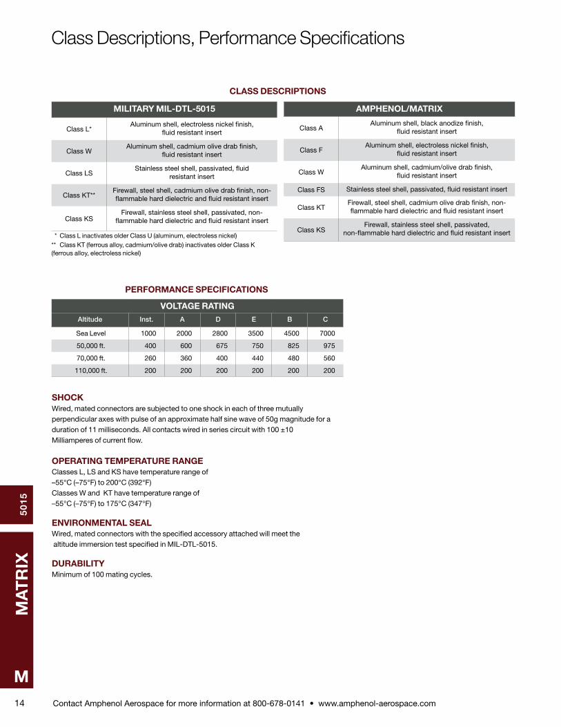
Class Descriptions, Performance Specifications
CLASS DESCRIPTIONS
MILITARY MIL-DTL-5015
Class L*Aluminum shell, electroless nickel finish,
fluid resistant insert
Class WAluminum shell, cadmium olive drab finish,
fluid resistant insert
Class LSStainless steel shell, passivated, fluid
resistant insert
Class KT**Firewall, steel shell, cadmium olive drab finish, non-flammable hard dielectric and fluid resistant insert
Class KSFirewall, stainless steel shell, passivated, non-
flamma ble hard dielectric and fluid resistant insert
* Class L inactivates older Class U (aluminum, electroless nickel)** Class KT (ferrous alloy, cadmium/olive drab) inactivates older Class K (ferrous alloy, electroless nickel)
AMPHENOL/MATRIX
Class AAluminum shell, black anodize finish,
fluid resistant insert
Class FAluminum shell, electroless nickel finish,
fluid resistant insert
Class WAluminum shell, cadmium/olive drab finish,
fluid resistant insert
Class FS Stainless steel shell, passivated, fluid resistant insert
Class KTFirewall, steel shell, cadmium olive drab finish, non-flammable hard dielectric and fluid resistant insert
Class KSFirewall, stainless steel shell, passivated,
non-flamma ble hard dielectric and fluid resistant insert
VOLTAGE RATINGAltitude Inst. A D E B C
Sea Level 1000 2000 2800 3500 4500 7000
50,000 ft . 400 600 675 750 825 975
70,000 ft . 260 360 400 440 480 560
110,000 ft . 200 200 200 200 200 200
PERFORMANCE SPECIFICATIONS
SHOCKWired, mated connectors are subjected to one shock in each of three mutu ally perpendicular axes with pulse of an approximate half sine wave of 50g magnitude for a duration of 11 milliseconds . All contacts wired in series cir cuit with 100 ±10 Milliamperes of current flow .
OPERATING TEMPERATURE RANGEClasses L, LS and KS have temperature range of –55°C (–75°F) to 200°C (392°F) Classes W and KT have temperature range of –55°C (–75°F) to 175°C (347°F)
ENVIRONMENTAL SEALWired, mated connectors with the specified accessory attached will meet the altitude immersion test specified in MIL-DTL-5015 .
DURABILITYMinimum of 100 mating cycles .
Contact Amphenol Aerospace for more information at 800-678-0141 • www.amphenol-aerospace.com
50
15
MA
TR
IX
M15
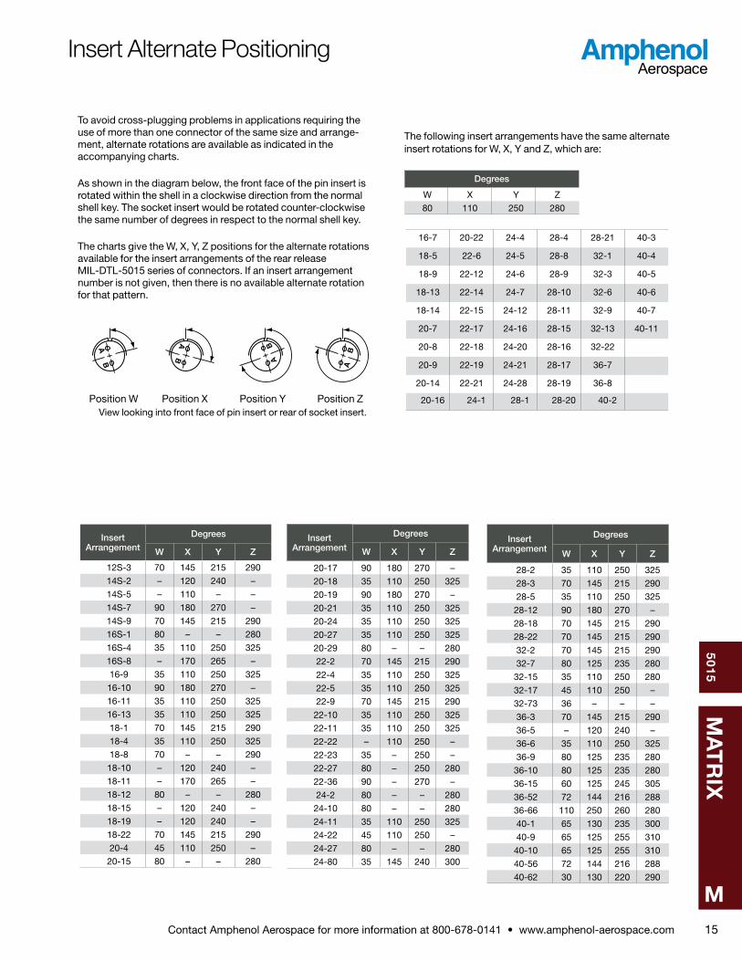
To avoid cross-plugging problems in applications requiring the use of more than one connector of the same size and arrange-ment, alternate rotations are available as indicated in the accompanying charts .
As shown in the diagram below, the front face of the pin insert is rotated within the shell in a clockwise direction from the normal shell key . The socket insert would be rotated counter-clockwise the same number of degrees in respect to the normal shell key .
The charts give the W, X, Y, Z positions for the alternate rotations available for the insert arrangements of the rear release MIL-DTL-5015 series of connectors . If an insert arrangement number is not given, then there is no available alternate rotation for that pattern .
AB
AB A
B
AB
The following insert arrangements have the same alternate insert rotations for W, X, Y and Z, which are:
Degrees
W X Y Z
80 110 250 280
16-7 20-22 24-4 28-4 28-21 40-3
18-5 22-6 24-5 28-8 32-1 40-4
18-9 22-12 24-6 28-9 32-3 40-5
18-13 22-14 24-7 28-10 32-6 40-6
18-14 22-15 24-12 28-11 32-9 40-7
20-7 22-17 24-16 28-15 32-13 40-11
20-8 22-18 24-20 28-16 32-22
20-9 22-19 24-21 28-17 36-7
20-14 22-21 24-28 28-19 36-8
20-16 24-1 28-1 28-20 40-2
Insert Arrangement
Degrees
W X Y Z
12S-3 70 145 215 290
14S-2 – 120 240 –
14S-5 – 110 – –
14S-7 90 180 270 –
14S-9 70 145 215 290
16S-1 80 – – 280
16S-4 35 110 250 325
16S-8 – 170 265 –
16-9 35 110 250 325
16-10 90 180 270 –
16-11 35 110 250 325
16-13 35 110 250 325
18-1 70 145 215 290
18-4 35 110 250 325
18-8 70 – – 290
18-10 – 120 240 –
18-11 – 170 265 –
18-12 80 – – 280
18-15 – 120 240 –
18-19 – 120 240 –
18-22 70 145 215 290
20-4 45 110 250 –
20-15 80 – – 280
Insert Arrangement
Degrees
W X Y Z
20-17 90 180 270 –
20-18 35 110 250 325
20-19 90 180 270 –
20-21 35 110 250 325
20-24 35 110 250 325
20-27 35 110 250 325
20-29 80 – – 280
22-2 70 145 215 290
22-4 35 110 250 325
22-5 35 110 250 325
22-9 70 145 215 290
22-10 35 110 250 325
22-11 35 110 250 325
22-22 – 110 250 –
22-23 35 – 250 –
22-27 80 – 250 280
22-36 90 – 270 –
24-2 80 – – 280
24-10 80 – – 280
24-11 35 110 250 325
24-22 45 110 250 –
24-27 80 – – 280
24-80 35 145 240 300
Insert Arrangement
Degrees
W X Y Z
28-2 35 110 250 325
28-3 70 145 215 290
28-5 35 110 250 325
28-12 90 180 270 –
28-18 70 145 215 290
28-22 70 145 215 290
32-2 70 145 215 290
32-7 80 125 235 280
32-15 35 110 250 280
32-17 45 110 250 –
32-73 36 – – –
36-3 70 145 215 290
36-5 – 120 240 –
36-6 35 110 250 325
36-9 80 125 235 280
36-10 80 125 235 280
36-15 60 125 245 305
36-52 72 144 216 288
36-66 110 250 260 280
40-1 65 130 235 300
40-9 65 125 255 310
40-10 65 125 255 310
40-56 72 144 216 288
40-62 30 130 220 290
Insert Alternate Positioning
Position W Position X Position Y Position Z View looking into front face of pin insert or rear of socket insert .
Contact Amphenol Aerospace for more information at 800-678-0141 • www.amphenol-aerospace.com
50
15
MA
TR
IX
M16
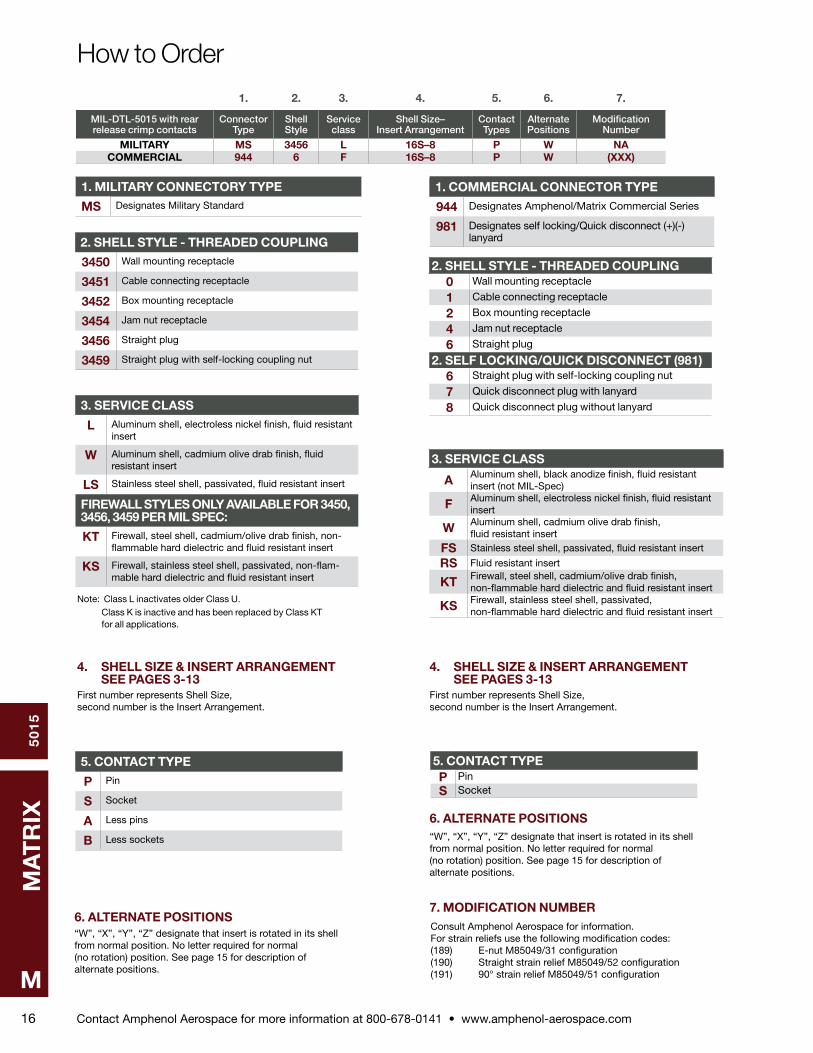
How to Order
1. 2. 3. 4. 5. 6. 7.
MIL-DTL-5015 with rear release crimp contacts
Connector Type
Shell Style
Service class
Shell Size– Insert Arrangement
Contact Types
Alternate Positions
Modification Number
MILITARY MS 3456 L 16S–8 P W NACOMMERCIAL 944 6 F 16S–8 P W (XXX)
2. SHELL STYLE - THREADED COUPLING
3450 Wall mounting receptacle
3451 Cable connecting receptacle
3452 Box mounting receptacle
3454 Jam nut receptacle
3456 Straight plug
3459 Straight plug with self-locking coupling nut
1. MILITARY CONNECTORY TYPE
MS Designates Military Standard
3. SERVICE CLASS
L Aluminum shell, electroless nickel finish, fluid resis tant insert
W Aluminum shell, cadmium olive drab finish, fluid resistant insert
LS Stainless steel shell, passivated, fluid resistant insert
FIREWALL STYLES ONLY AVAILABLE FOR 3450, 3456, 3459 PER MIL SPEC:
KT Firewall, steel shell, cadmium/olive drab finish, non-flammable hard dielectric and fluid resistant insert
KS Firewall, stainless steel shell, passivated, non-flam-mable hard dielectric and fluid resistant insert
4. SHELL SIZE & INSERT ARRANGEMENT SEE PAGES 3-13First number represents Shell Size, second number is the Insert Arrangement .
5. CONTACT TYPE
P Pin
S Socket
A Less pins
B Less sockets
Note: Class L inactivates older Class U . Class K is inactive and has been replaced by Class KT for all applications .
6. ALTERNATE POSITIONS“W”, “X”, “Y”, “Z” designate that insert is rotated in its shell from normal position . No letter required for normal (no rotation) position . See page 15 for description of alternate positions .
2. SHELL STYLE - THREADED COUPLING0 Wall mounting receptacle
1 Cable connecting receptacle
2 Box mounting receptacle
4 Jam nut receptacle
6 Straight plug
2. SELF LOCKING/QUICK DISCONNECT (981)6 Straight plug with self-locking coupling nut
7 Quick disconnect plug with lanyard
8 Quick disconnect plug without lanyard
1. COMMERCIAL CONNECTOR TYPE
944 Designates Amphenol/Matrix Commercial Series
981 Designates self locking/Quick disconnect (+)(-) lanyard
3. SERVICE CLASS
A Aluminum shell, black anodize finish, fluid resistant insert (not MIL-Spec)
F Aluminum shell, electroless nickel finish, fluid resis tant insert
W Aluminum shell, cadmium olive drab finish, fluid resistant insert
FS Stainless steel shell, passivated, fluid resistant insert
RS Fluid resistant insert
KT Firewall, steel shell, cadmium/olive drab finish, non-flammable hard dielectric and fluid resistant insert
KS Firewall, stainless steel shell, passivated, non-flam mable hard dielectric and fluid resistant insert
5. CONTACT TYPEP PinS Socket
6. ALTERNATE POSITIONS“W”, “X”, “Y”, “Z” designate that insert is rotated in its shell from normal position . No letter required for normal (no rotation) position . See page 15 for description of alternate positions .
Consult Amphenol Aerospace for information . For strain reliefs use the following modification codes:(189) E-nut M85049/31 configuration (190) Straight strain relief M85049/52 configuration (191) 90° strain relief M85049/51 configuration
7. MODIFICATION NUMBER
4. SHELL SIZE & INSERT ARRANGEMENT SEE PAGES 3-13First number represents Shell Size, second number is the Insert Arrangement .
Contact Amphenol Aerospace for more information at 800-678-0141 • www.amphenol-aerospace.com
50
15
MA
TR
IX
M17
H Accessory Thread
3 Teeth EquallyPlaced 120 Apart
Blue Color Band
E Dia.Max
G Min. FullThread
J CouplingThread
D Max.
F K
Polarizing Key
A Typ.
B Typ.
B Typ.
PANEL CUTOUT
C Dia.4 Holes
C Dia.
L Dia.
˚
Shell Size*
A ±.031 B
C Dia. +.010 –.005
D Max.E
Dia. Max.
F G Min.
H Thread
Class 2A
J Thread
Class 2AK
L Dia.
±.010Class A, F, R,
W
Class K
Size 16 & 12
Contacts
Size 8, 4, 0
Contacts
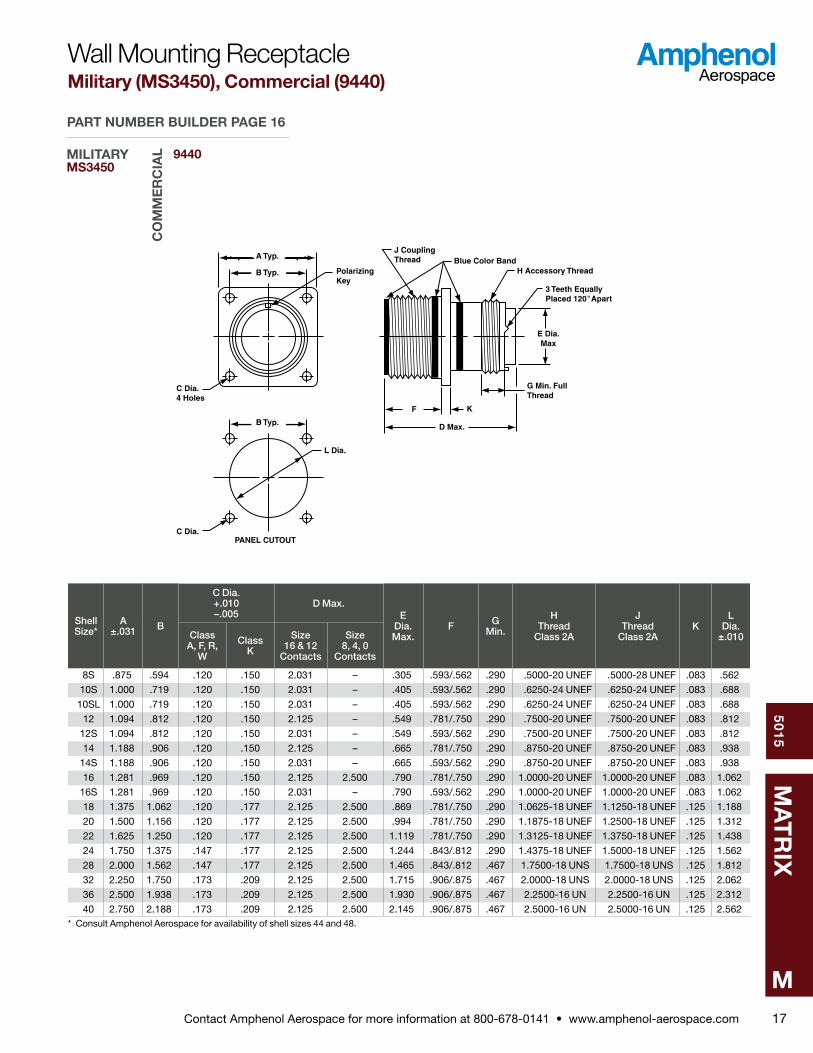
8S .875 .594 .120 .150 2 .031 – .305 .593/ .562 .290 .5000-20 UNEF .5000-28 UNEF .083 .562
10S 1 .000 .719 .120 .150 2 .031 – .405 .593/ .562 .290 .6250-24 UNEF .6250-24 UNEF .083 .688
10SL 1 .000 .719 .120 .150 2 .031 – .405 .593/ .562 .290 .6250-24 UNEF .6250-24 UNEF .083 .688
12 1 .094 .812 .120 .150 2 .125 – .549 .781/ .750 .290 .7500-20 UNEF .7500-20 UNEF .083 .812
12S 1 .094 .812 .120 .150 2 .031 – .549 .593/ .562 .290 .7500-20 UNEF .7500-20 UNEF .083 .812
14 1 .188 .906 .120 .150 2 .125 – .665 .781/ .750 .290 .8750-20 UNEF .8750-20 UNEF .083 .938
14S 1 .188 .906 .120 .150 2 .031 – .665 .593/ .562 .290 .8750-20 UNEF .8750-20 UNEF .083 .938
16 1 .281 .969 .120 .150 2 .125 2 .500 .790 .781/ .750 .290 1 .0000-20 UNEF 1 .0000-20 UNEF .083 1 .062
16S 1 .281 .969 .120 .150 2 .031 – .790 .593/ .562 .290 1 .0000-20 UNEF 1 .0000-20 UNEF .083 1 .062
18 1 .375 1 .062 .120 .177 2 .125 2 .500 .869 .781/ .750 .290 1 .0625-18 UNEF 1 .1250-18 UNEF .125 1 .188
20 1 .500 1 .156 .120 .177 2 .125 2 .500 .994 .781/ .750 .290 1 .1875-18 UNEF 1 .2500-18 UNEF .125 1 .312
22 1 .625 1 .250 .120 .177 2 .125 2 .500 1 .119 .781/ .750 .290 1 .3125-18 UNEF 1 .3750-18 UNEF .125 1 .438
24 1 .750 1 .375 .147 .177 2 .125 2 .500 1 .244 .843/ .812 .290 1 .4375-18 UNEF 1 .5000-18 UNEF .125 1 .562
28 2 .000 1 .562 .147 .177 2 .125 2 .500 1 .465 .843/ .812 .467 1 .7500-18 UNS 1 .7500-18 UNS .125 1 .812
32 2 .250 1 .750 .173 .209 2 .125 2 .500 1 .715 .906/ .875 .467 2 .0000-18 UNS 2 .0000-18 UNS .125 2 .062
36 2 .500 1 .938 .173 .209 2 .125 2 .500 1 .930 .906/ .875 .467 2 .2500-16 UN 2 .2500-16 UN .125 2 .312
40 2 .750 2 .188 .173 .209 2 .125 2 .500 2 .145 .906/ .875 .467 2 .5000-16 UN 2 .5000-16 UN .125 2 .562* Consult Amphenol Aerospace for availability of shell sizes 44 and 48 .
Wall Mounting ReceptacleMilitary (MS3450), Commercial (9440)
9440MILITARYMS3450
CO
MM
ER
CIA
L
PART NUMBER BUILDER PAGE 16
Contact Amphenol Aerospace for more information at 800-678-0141 • www.amphenol-aerospace.com
50
15
MA
TR
IX
M18
H Accessory Thread
3 Teeth EquallyPlaced 120 Apart
Blue Color Band
E Dia.Max
J CouplingThread
D Max.
F
G
Polarizing Key
C
BDia.
A
˚
Shell Size A
B Dia.
±.031C
D Max.E
Dia. Max.
F ±.015
G Min.
H Thread
Class 2A
J Thread
Class 2ASize
16 & 12 Contacts
Size 8, 4, 0
Contacts
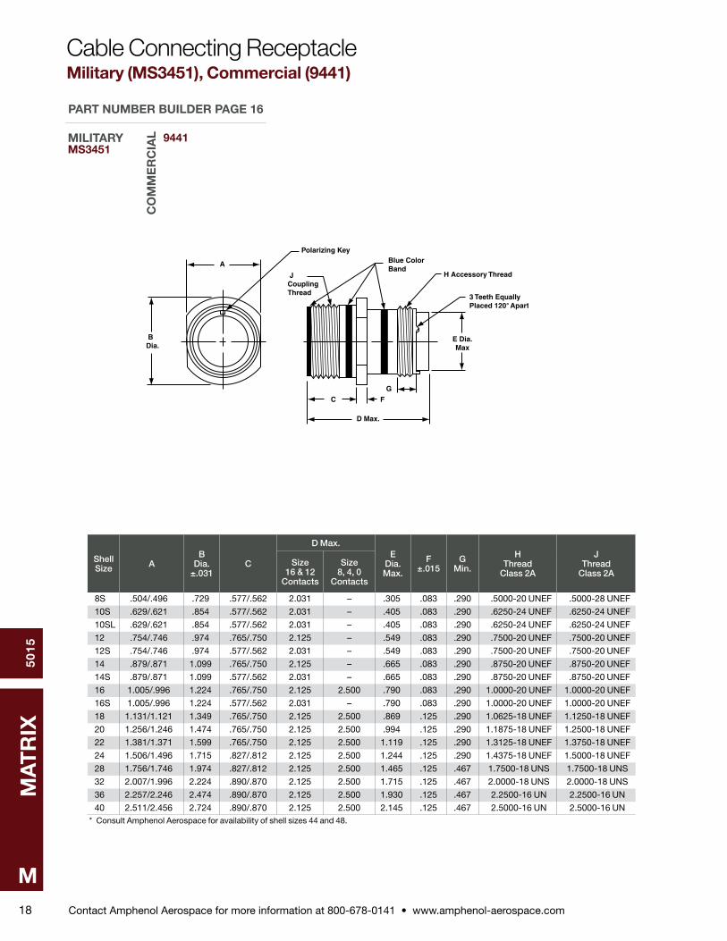
8S .504/ .496 .729 .577/ .562 2 .031 – .305 .083 .290 .5000-20 UNEF .5000-28 UNEF
10S .629/ .621 .854 .577/ .562 2 .031 – .405 .083 .290 .6250-24 UNEF .6250-24 UNEF
10SL .629/ .621 .854 .577/ .562 2 .031 – .405 .083 .290 .6250-24 UNEF .6250-24 UNEF
12 .754/ .746 .974 .765/ .750 2 .125 – .549 .083 .290 .7500-20 UNEF .7500-20 UNEF
12S .754/ .746 .974 .577/ .562 2 .031 – .549 .083 .290 .7500-20 UNEF .7500-20 UNEF
14 .879/ .871 1 .099 .765/ .750 2 .125 – .665 .083 .290 .8750-20 UNEF .8750-20 UNEF
14S .879/ .871 1 .099 .577/ .562 2 .031 – .665 .083 .290 .8750-20 UNEF .8750-20 UNEF
16 1 .005/ .996 1 .224 .765/ .750 2 .125 2 .500 .790 .083 .290 1 .0000-20 UNEF 1 .0000-20 UNEF
16S 1 .005/ .996 1 .224 .577/ .562 2 .031 – .790 .083 .290 1 .0000-20 UNEF 1 .0000-20 UNEF
18 1 .131/1 .121 1 .349 .765/ .750 2 .125 2 .500 .869 .125 .290 1 .0625-18 UNEF 1 .1250-18 UNEF
20 1 .256/1 .246 1 .474 .765/ .750 2 .125 2 .500 .994 .125 .290 1 .1875-18 UNEF 1 .2500-18 UNEF
22 1 .381/1 .371 1 .599 .765/ .750 2 .125 2 .500 1 .119 .125 .290 1 .3125-18 UNEF 1 .3750-18 UNEF
24 1 .506/1 .496 1 .715 .827/ .812 2 .125 2 .500 1 .244 .125 .290 1 .4375-18 UNEF 1 .5000-18 UNEF
28 1 .756/1 .746 1 .974 .827/ .812 2 .125 2 .500 1 .465 .125 .467 1 .7500-18 UNS 1 .7500-18 UNS
32 2 .007/1 .996 2 .224 .890/ .870 2 .125 2 .500 1 .715 .125 .467 2 .0000-18 UNS 2 .0000-18 UNS
36 2 .257/2 .246 2 .474 .890/ .870 2 .125 2 .500 1 .930 .125 .467 2 .2500-16 UN 2 .2500-16 UN
40 2 .511/2 .456 2 .724 .890/ .870 2 .125 2 .500 2 .145 .125 .467 2 .5000-16 UN 2 .5000-16 UN* Consult Amphenol Aerospace for availability of shell sizes 44 and 48 .
Cable Connecting ReceptacleMilitary (MS3451), Commercial (9441)
9441MILITARYMS3451
CO
MM
ER
CIA
L
PART NUMBER BUILDER PAGE 16
Contact Amphenol Aerospace for more information at 800-678-0141 • www.amphenol-aerospace.com
50
15
MA
TR
IX
M19
Blue Color Band
E Dia.Max
J CouplingThread
D Max.
F G
Polarizing Key
A Typ.
B Typ.
B Typ.
PANEL CUTOUT
C Dia.4 Holes
C Dia.
L Dia.
Shell Size*
A ±.031 B C
Dia.
D Max.E
Dia. ±.016
F G ±.015
J Thread
Class 2A
L Dia.
±.010Size
16 & 12 Contacts
Size 8, 4, 0
Contacts
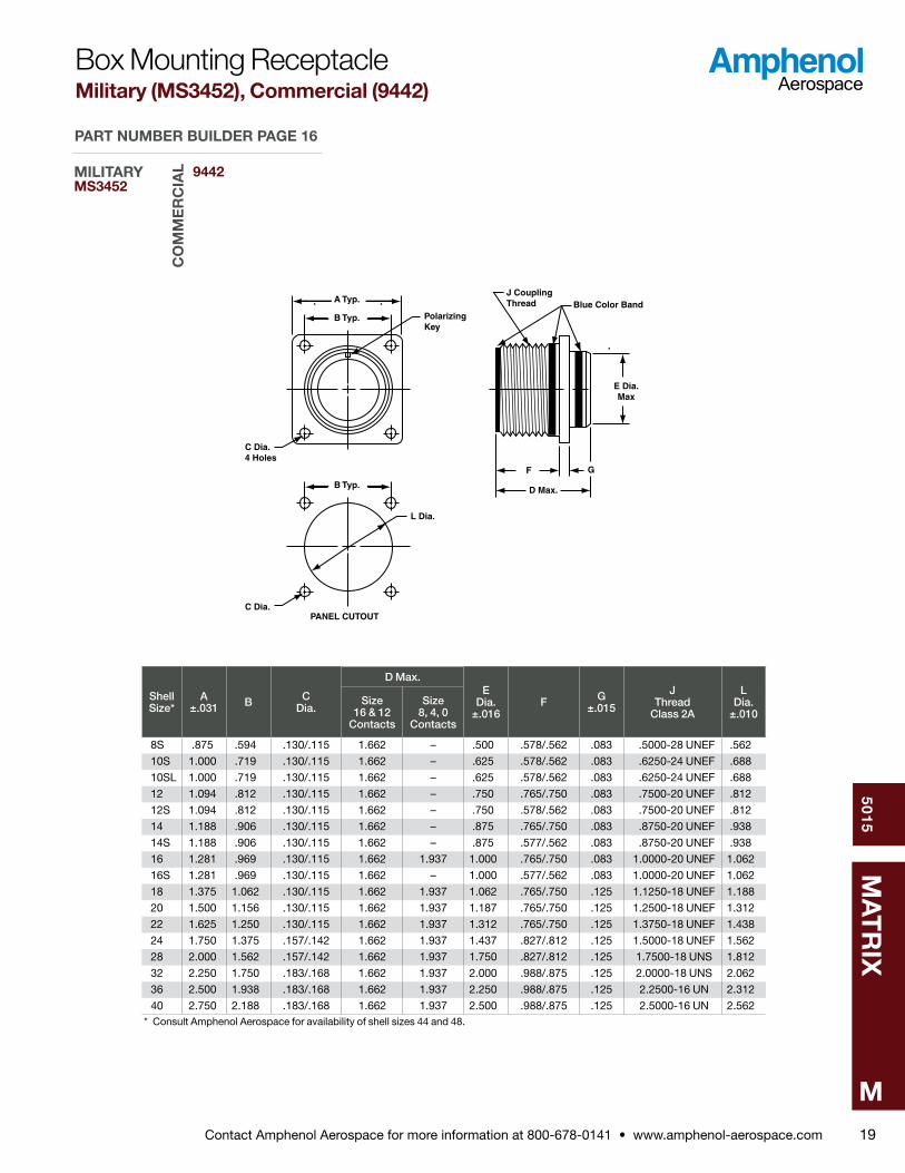
8S .875 .594 .130/ .115 1 .662 – .500 .578/ .562 .083 .5000-28 UNEF .562
10S 1 .000 .719 .130/ .115 1 .662 – .625 .578/ .562 .083 .6250-24 UNEF .688
10SL 1 .000 .719 .130/ .115 1 .662 – .625 .578/ .562 .083 .6250-24 UNEF .688
12 1 .094 .812 .130/ .115 1 .662 – .750 .765/ .750 .083 .7500-20 UNEF .812
12S 1 .094 .812 .130/ .115 1 .662 – .750 .578/ .562 .083 .7500-20 UNEF .812
14 1 .188 .906 .130/ .115 1 .662 – .875 .765/ .750 .083 .8750-20 UNEF .938
14S 1 .188 .906 .130/ .115 1 .662 – .875 .577/ .562 .083 .8750-20 UNEF .938
16 1 .281 .969 .130/ .115 1 .662 1 .937 1 .000 .765/ .750 .083 1 .0000-20 UNEF 1 .062
16S 1 .281 .969 .130/ .115 1 .662 – 1 .000 .577/ .562 .083 1 .0000-20 UNEF 1 .062
18 1 .375 1 .062 .130/ .115 1 .662 1 .937 1 .062 .765/ .750 .125 1 .1250-18 UNEF 1 .188
20 1 .500 1 .156 .130/ .115 1 .662 1 .937 1 .187 .765/ .750 .125 1 .2500-18 UNEF 1 .312
22 1 .625 1 .250 .130/ .115 1 .662 1 .937 1 .312 .765/ .750 .125 1 .3750-18 UNEF 1 .438
24 1 .750 1 .375 .157/ .142 1 .662 1 .937 1 .437 .827/ .812 .125 1 .5000-18 UNEF 1 .562
28 2 .000 1 .562 .157/ .142 1 .662 1 .937 1 .750 .827/ .812 .125 1 .7500-18 UNS 1 .812
32 2 .250 1 .750 .183/ .168 1 .662 1 .937 2 .000 .988/ .875 .125 2 .0000-18 UNS 2 .062
36 2 .500 1 .938 .183/ .168 1 .662 1 .937 2 .250 .988/ .875 .125 2 .2500-16 UN 2 .312
40 2 .750 2 .188 .183/ .168 1 .662 1 .937 2 .500 .988/ .875 .125 2 .5000-16 UN 2 .562* Consult Amphenol Aerospace for availability of shell sizes 44 and 48 .
Box Mounting ReceptacleMilitary (MS3452), Commercial (9442)
9442MILITARYMS3452
CO
MM
ER
CIA
L
PART NUMBER BUILDER PAGE 16

Contact Amphenol Aerospace for more information at 800-678-0141 • www.amphenol-aerospace.com
50
15
MA
TR
IX
M20
PANEL CUTOUT
Blue ColorBand
J CouplingThread
Pin Protrusion
A Typ. .045.035
.180
.165
.128 Max.Panel Thickness
GMin. Full Thread
3 TeethEqually Spaced120 Apart
H AccessoryThread
.100
.095.196.186
MDia.
CDia.
BTyp.
EDia
Max.
PolarizingKey
L
D Max
F
O-Ring
˚
Shell Size*
A ±.010
B ±.005
C Dia.
±.005
D Max.E
Dia. Max.
F ±.005
G Min.
H Thread
Class 2A
J Thread
Class 2A
Panel Cutout Dimensions
Size 16 & 12
Contacts
Size 8, 4, 0
Contacts
L ±.005
M Dia. +.015 –.000
8S .687 1 .187 1 .272 2 .031 – .305 .720 .290 .5000-20 UNEF .5000-28 UNEF .323 .505
10S .812 1 .312 1 .397 2 .031 – .405 .720 .290 .6250-24 UNEF .6250-24 UNEF .385 .630
10SL .812 1 .312 1 .397 2 .031 – .405 .720 .290 .6250-24 UNEF .6250-24 UNEF .385 .630
12 .937 1 .437 1 .522 2 .125 – .549 .970 .290 .7500-20 UNEF .7500-20 UNEF .448 .755
12S .937 1 .437 1 .522 2 .031 – .549 .720 .290 .7500-20 UNEF .7500-20 UNEF .448 .755
14 1 .125 1 .562 1 .647 2 .125 – .665 .970 .290 .8750-20 UNEF .8750-20 UNEF .510 .880
14S 1 .125 1 .562 1 .647 2 .031 – .665 .720 .290 .8750-20 UNEF .8750-20 UNEF .510 .880
16 1 .250 1 .687 1 .772 2 .125 2 .500 .790 .970 .290 1 .0000-20 UNEF 1 .0000-20 UNEF .573 1 .005
16S 1 .250 1 .687 1 .772 2 .031 – .790 .720 .290 1 .0000-20 UNEF 1 .0000-20 UNEF .573 1 .005
18 1 .375 1 .812 1 .897 2 .125 2 .500 .869 .970 .290 1 .0625-18 UNEF 1 .1250-18 UNEF .635 1 .130
20 1 .500 1 .937 2 .022 2 .125 2 .500 .994 .970 .290 1 .1875-18 UNEF 1 .2500-18 UNEF .698 1 .255
22 1 .625 2 .156 2 .241 2 .125 2 .500 1 .119 .970 .290 1 .3125-18 UNEF 1 .3750-18 UNEF .760 1 .380
24 1 .750 2 .281 2 .366 2 .125 2 .500 1 .244 .970 .290 1 .4375-18 UNEF 1 .5000-18 UNEF .823 1 .505
28 2 .000 2 .531 2 .616 2 .125 2 .500 1 .465 .970 .467 1 .7500-18 UNS 1 .7500-18 UNS .948 1 .755
32 2 .375 2 .781 2 .866 2 .125 2 .500 1 .715 .970 .467 2 .0000-18 UNS 2 .0000-18 UNS 1 .073 2 .005
36 2 .625 3 .031 3 .116 2 .125 2 .500 1 .930 .970 .467 2 .2500-16 UN 2 .2500-16 UN 1 .198 2 .255
40 2 .875 3 .281 3 .366 2 .125 2 .500 2 .145 .970 .467 2 .5000-16 UN 2 .5000-16 UN 1 .323 2 .505* Consult Amphenol Aerospace for availability of shell sizes 44 and 48 .
Jam Nut ReceptacleMilitary (MS3454), Commercial (9444)
9444MILITARYMS3454
CO
MM
ER
CIA
L
PART NUMBER BUILDER PAGE 16
Contact Amphenol Aerospace for more information at 800-678-0141 • www.amphenol-aerospace.com
50
15
MA
TR
IX
M21
Polarizing Keyway
Blue Color Band
H Accessory ThreadJ CouplingThread
3 TeethEqually Spaced120 Apart
D Min. FullThread
C Max.
BDia.
EDia
Max.
ADia Max.
˚
Shell Size*
A Dia. Max.
B Dia.
±.005
C Max.
D Min.
E Dia. Max.
H Thread
Class 2A
J Thread
Class 2BSize
16 & 12 Contacts
Size 8, 4, 0
Contacts
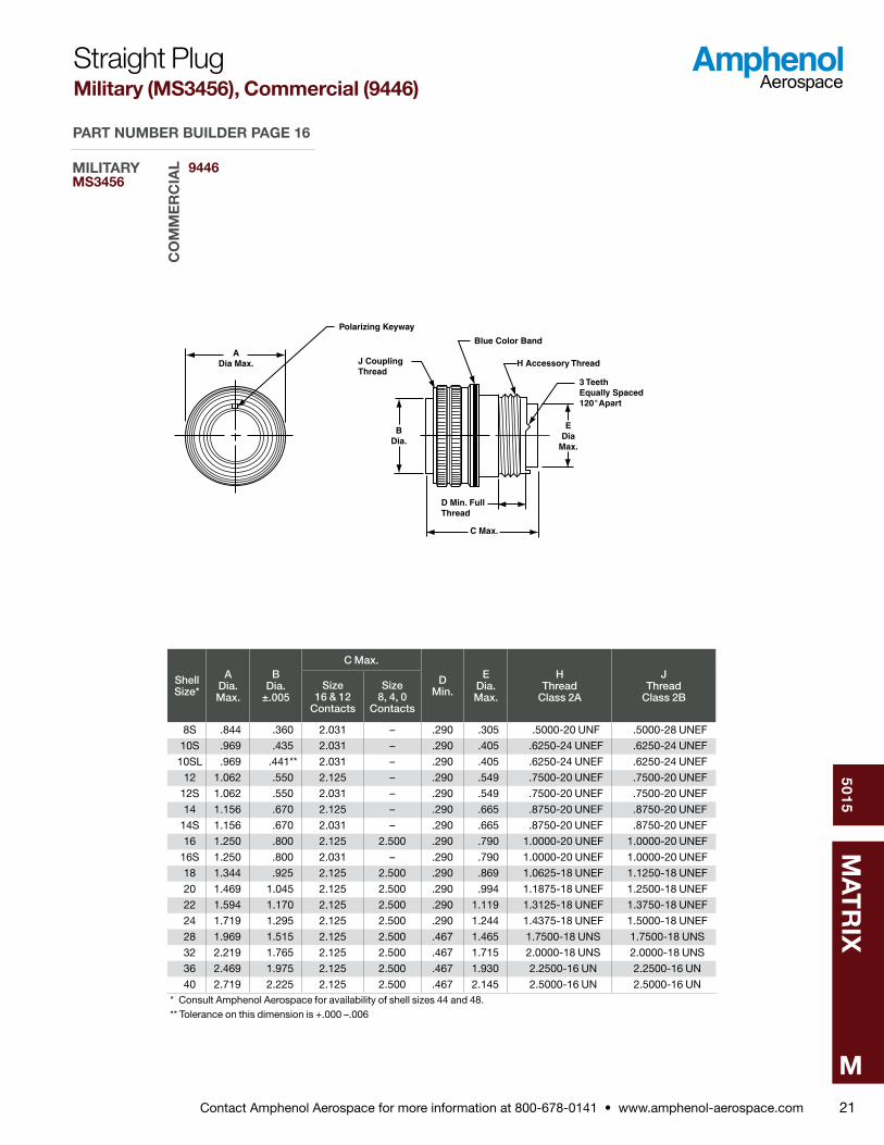
8S .844 .360 2 .031 – .290 .305 .5000-20 UNF .5000-28 UNEF
10S .969 .435 2 .031 – .290 .405 .6250-24 UNEF .6250-24 UNEF
10SL .969 .441** 2 .031 – .290 .405 .6250-24 UNEF .6250-24 UNEF
12 1 .062 .550 2 .125 – .290 .549 .7500-20 UNEF .7500-20 UNEF
12S 1 .062 .550 2 .031 – .290 .549 .7500-20 UNEF .7500-20 UNEF
14 1 .156 .670 2 .125 – .290 .665 .8750-20 UNEF .8750-20 UNEF
14S 1 .156 .670 2 .031 – .290 .665 .8750-20 UNEF .8750-20 UNEF
16 1 .250 .800 2 .125 2 .500 .290 .790 1 .0000-20 UNEF 1 .0000-20 UNEF
16S 1 .250 .800 2 .031 – .290 .790 1 .0000-20 UNEF 1 .0000-20 UNEF
18 1 .344 .925 2 .125 2 .500 .290 .869 1 .0625-18 UNEF 1 .1250-18 UNEF
20 1 .469 1 .045 2 .125 2 .500 .290 .994 1 .1875-18 UNEF 1 .2500-18 UNEF
22 1 .594 1 .170 2 .125 2 .500 .290 1 .119 1 .3125-18 UNEF 1 .3750-18 UNEF
24 1 .719 1 .295 2 .125 2 .500 .290 1 .244 1 .4375-18 UNEF 1 .5000-18 UNEF
28 1 .969 1 .515 2 .125 2 .500 .467 1 .465 1 .7500-18 UNS 1 .7500-18 UNS
32 2 .219 1 .765 2 .125 2 .500 .467 1 .715 2 .0000-18 UNS 2 .0000-18 UNS
36 2 .469 1 .975 2 .125 2 .500 .467 1 .930 2 .2500-16 UN 2 .2500-16 UN
40 2 .719 2 .225 2 .125 2 .500 .467 2 .145 2 .5000-16 UN 2 .5000-16 UN* Consult Amphenol Aerospace for availability of shell sizes 44 and 48 .** Tolerance on this dimension is + .000 – .006
Straight PlugMilitary (MS3456), Commercial (9446)
9446MILITARYMS3456
CO
MM
ER
CIA
L
PART NUMBER BUILDER PAGE 16
Contact Amphenol Aerospace for more information at 800-678-0141 • www.amphenol-aerospace.com
50
15
MA
TR
IX
M22
Polarizing Keyway
Blue Color BandH Accessory Thread
Fully CoupledIndicator
J CouplingThread
D Min. FullThread
C Max.Clutch Plate
BDia.
EDia
Max.
ADia Max.
3 TeethEqually Spaced120 Apart˚
Shell Size*
A Dia. Max.
B Dia.
±.005
C Max.
D Min.
E Dia. Max.
H Thread
Class 2A
J Thread
Class 2BSize
16 & 12 Contacts
Size 8, 4, 0
Contacts
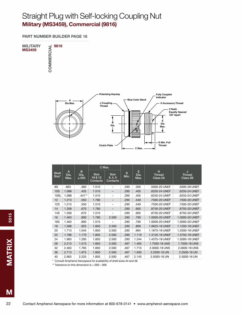
8S .963 .360 1 .510 – .290 .305 .5000-20 UNEF .5000-28 UNEF
10S 1 .088 .435 1 .510 – .290 .405 .6250-24 UNEF .6250-24 UNEF
10SL 1 .088 .441** 1 .510 – .290 .405 .6250-24 UNEF .6250-24 UNEF
12 1 .213 .550 1 .780 – .290 .549 .7500-20 UNEF .7500-20 UNEF
12S 1 .213 .550 1 .510 – .290 .549 .7500-20 UNEF .7500-20 UNEF
14 1 .358 .670 1 .780 – .290 .665 .8750-20 UNEF .8750-20 UNEF
14S 1 .358 .670 1 .510 – .290 .665 .8750-20 UNEF .8750-20 UNEF
16 1 .463 .800 1 .780 2 .500 .290 .790 1 .0000-20 UNEF 1 .0000-20 UNEF
16S 1 .463 .800 1 .510 – .290 .790 1 .0000-20 UNEF 1 .0000-20 UNEF
18 1 .588 .925 1 .850 2 .500 .290 .869 1 .0625-18 UNEF 1 .1250-18 UNEF
20 1 .713 1 .045 1 .850 2 .500 .290 .994 1 .1875-18 UNEF 1 .2500-18 UNEF
22 1 .788 1 .170 1 .850 2 .500 .290 1 .119 1 .3125-18 UNEF 1 .3750-18 UNEF
24 1 .963 1 .295 1 .850 2 .500 .290 1 .244 1 .4375-18 UNEF 1 .5000-18 UNEF
28 2 .213 1 .515 1 .850 2 .500 .467 1 .465 1 .7500-18 UNS 1 .7500-18 UNS
32 2 .463 1 .765 1 .850 2 .500 .467 1 .715 2 .0000-18 UNS 2 .0000-18 UNS
36 2 .713 1 .975 1 .850 2 .500 .467 1 .930 2 .2500-16 UN 2 .2500-16 UN
40 2 .963 2 .225 1 .850 2 .500 .467 2 .145 2 .5000-16 UN 2 .5000-16 UN* Consult Amphenol Aerospace for availability of shell sizes 44 and 48 .** Tolerance on this dimension is + .000 – .006
Straight Plug with Self-locking Coupling NutMilitary (MS3459), Commercial (9816)
9816MILITARYMS3459
CO
MM
ER
CIA
L
PART NUMBER BUILDER PAGE 16
Contact Amphenol Aerospace for more information at 800-678-0141 • www.amphenol-aerospace.com
50
15
MA
TR
IX
M23
Polarizing Keyway
H Thread
C Max.
D Min. Perf.Thread
7.500 MaxBlue Color Band DesignatesRear Release Contact Connector
ADia Max.
E Dia. Max.B Dia.
.061
.046
3 TeethEqually Spaced120 Apart˚
Adapter
Mating Face ofReceptacle Shell
Shell Size*
A Dia. Max.
B Dia.
C Max. D Min.
E Dia. Max.
H Thread
Class 2A
Amphenol/Matrix Part Number for
Adapter RingSize
16 & 12 Contacts
Size 8, 4, 0
Contacts
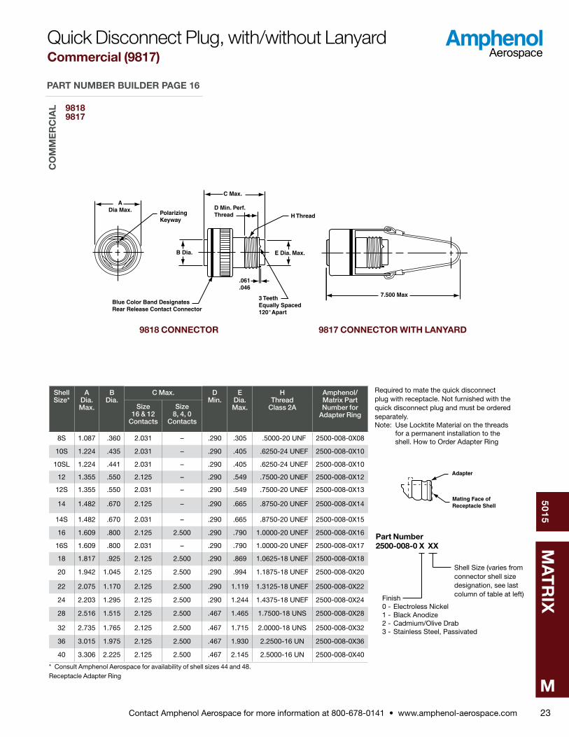
8S 1 .087 .360 2 .031 – .290 .305 .5000-20 UNF 2500-008-0X08
10S 1 .224 .435 2 .031 – .290 .405 .6250-24 UNEF 2500-008-0X10
10SL 1 .224 .441 2 .031 – .290 .405 .6250-24 UNEF 2500-008-0X10
12 1 .355 .550 2 .125 – .290 .549 .7500-20 UNEF 2500-008-0X12
12S 1 .355 .550 2 .031 – .290 .549 .7500-20 UNEF 2500-008-0X13
14 1 .482 .670 2 .125 – .290 .665 .8750-20 UNEF 2500-008-0X14
14S 1 .482 .670 2 .031 – .290 .665 .8750-20 UNEF 2500-008-0X15
16 1 .609 .800 2 .125 2 .500 .290 .790 1 .0000-20 UNEF 2500-008-0X16
16S 1 .609 .800 2 .031 – .290 .790 1 .0000-20 UNEF 2500-008-0X17
18 1 .817 .925 2 .125 2 .500 .290 .869 1 .0625-18 UNEF 2500-008-0X18
20 1 .942 1 .045 2 .125 2 .500 .290 .994 1 .1875-18 UNEF 2500-008-0X20
22 2 .075 1 .170 2 .125 2 .500 .290 1 .119 1 .3125-18 UNEF 2500-008-0X22
24 2 .203 1 .295 2 .125 2 .500 .290 1 .244 1 .4375-18 UNEF 2500-008-0X24
28 2 .516 1 .515 2 .125 2 .500 .467 1 .465 1 .7500-18 UNS 2500-008-0X28
32 2 .735 1 .765 2 .125 2 .500 .467 1 .715 2 .0000-18 UNS 2500-008-0X32
36 3 .015 1 .975 2 .125 2 .500 .467 1 .930 2 .2500-16 UN 2500-008-0X36
40 3 .306 2 .225 2 .125 2 .500 .467 2 .145 2 .5000-16 UN 2500-008-0X40
* Consult Amphenol Aerospace for availability of shell sizes 44 and 48 .Receptacle Adapter Ring
Required to mate the quick disconnect plug with receptacle . Not furnished with the quick disconnect plug and must be ordered separately .Note: Use Locktite Material on the threads for a permanent installation to the shell . How to Order Adapter Ring
Part Number 2500-008-0 X XX
Finish0 - Electroless Nickel1 - Black Anodize2 - Cadmium/Olive Drab3 - Stainless Steel, Passivated
9818 CONNECTOR 9817 CONNECTOR WITH LANYARD
Quick Disconnect Plug, with/without LanyardCommercial (9817)
Shell Size (varies from connector shell size designation, see last column of table at left)
98189817
CO
MM
ER
CIA
L
PART NUMBER BUILDER PAGE 16
Contact Amphenol Aerospace for more information at 800-678-0141 • www.amphenol-aerospace.com
50
15
MA
TR
IX
M24
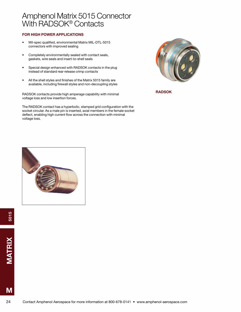
Amphenol Matrix 5015 ConnectorWith RADSOK® ContactsFOR HIGH POWER APPLICATIONS
• Mil-spec qualified, environmental Matrix MIL-DTL-5015 connectors with improved sealing • Completely environmentally sealed with contact seals, gaskets, wire seals and insert-to-shell seals • Special design enhanced with RADSOK contacts in the plug instead of standard rear release crimp contacts • All the shell styles and finishes of the Matrix 5015 family are available, including firewall styles and non-decoupling styles
RADSOK contacts provide high amperage capability with minimal voltage loss and low insertion forces .
The RADSOK contact has a hyperbolic, stamped grid configuration with the socket circular . As a male pin is inserted, axial members in the female socket deflect, enabling high current flow across the connection with minimal voltage loss .
RADSOK
Contact Amphenol Aerospace for more information at 800-678-0141 • www.amphenol-aerospace.com
50
15
MA
TR
IX
M25
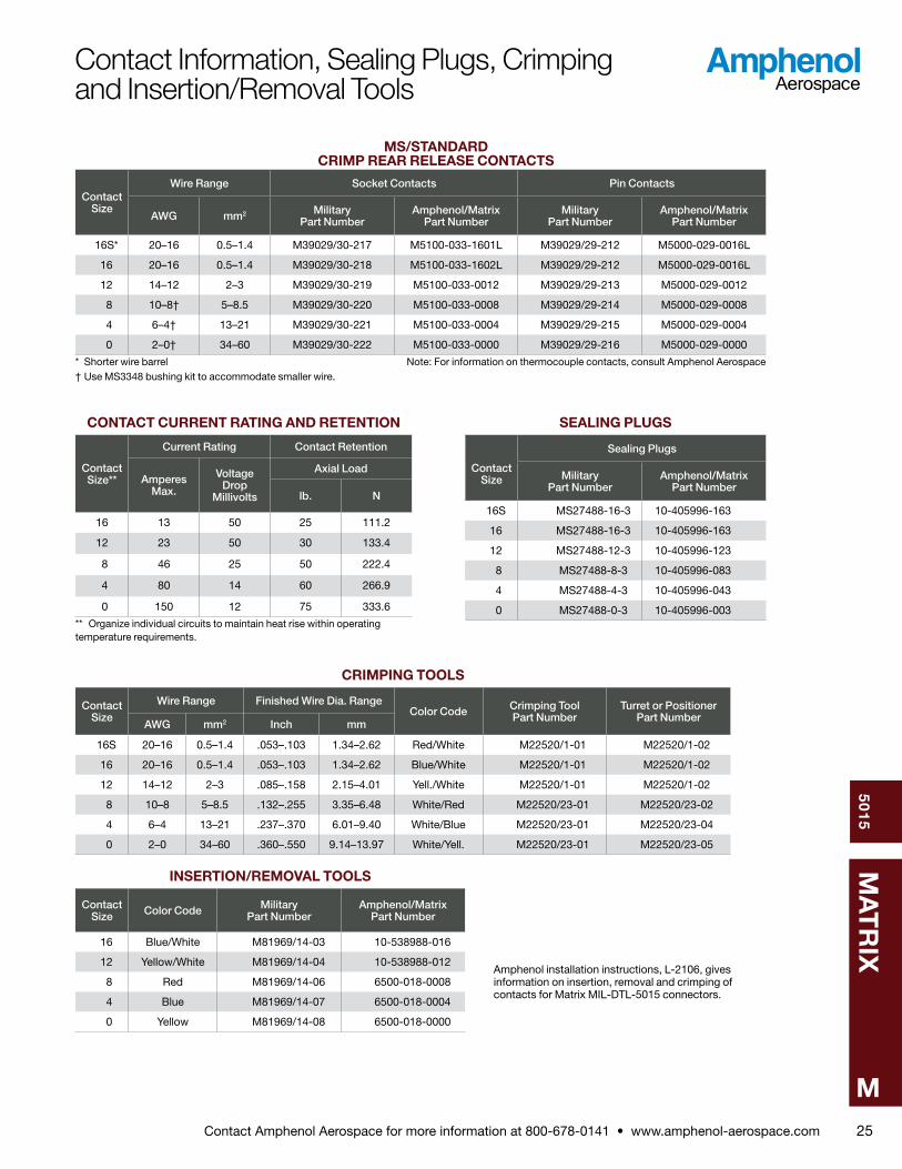
MS/STANDARD CRIMP REAR RELEASE CONTACTS
Contact Size
Wire Range Socket Contacts Pin Contacts
AWG mm2 Military Part Number
Amphenol/Matrix Part Number
Military Part Number
Amphenol/Matrix Part Number
16S* 20–16 0 .5–1 .4 M39029/30-217 M5100-033-1601L M39029/29-212 M5000-029-0016L
16 20–16 0 .5–1 .4 M39029/30-218 M5100-033-1602L M39029/29-212 M5000-029-0016L
12 14–12 2–3 M39029/30-219 M5100-033-0012 M39029/29-213 M5000-029-0012
8 10–8† 5–8 .5 M39029/30-220 M5100-033-0008 M39029/29-214 M5000-029-0008
4 6–4† 13–21 M39029/30-221 M5100-033-0004 M39029/29-215 M5000-029-0004
0 2–0† 34–60 M39029/30-222 M5100-033-0000 M39029/29-216 M5000-029-0000
* Shorter wire barrel Note: For information on thermocouple contacts, consult Amphenol Aerospace† Use MS3348 bushing kit to accommodate smaller wire .
CONTACT CURRENT RATING AND RETENTION
Contact Size**
Current Rating Contact Retention
Amperes Max.
Voltage Drop
Millivolts
Axial Load
lb. N
16 13 50 25 111 .2
12 23 50 30 133 .4
8 46 25 50 222 .4
4 80 14 60 266 .9
0 150 12 75 333 .6
** Organize individual circuits to maintain heat rise within operating temperature requirements .
SEALING PLUGS
Contact Size
Sealing Plugs
Military Part Number
Amphenol/Matrix Part Number
16S MS27488-16-3 10-405996-163
16 MS27488-16-3 10-405996-163
12 MS27488-12-3 10-405996-123
8 MS27488-8-3 10-405996-083
4 MS27488-4-3 10-405996-043
0 MS27488-0-3 10-405996-003
CRIMPING TOOLS
Contact Size
Wire Range Finished Wire Dia. RangeColor Code Crimping Tool
Part NumberTurret or Positioner
Part NumberAWG mm2 Inch mm
16S 20–16 0 .5–1 .4 .053– .103 1 .34–2 .62 Red/White M22520/1-01 M22520/1-02
16 20–16 0 .5–1 .4 .053– .103 1 .34–2 .62 Blue/White M22520/1-01 M22520/1-02
12 14–12 2–3 .085– .158 2 .15–4 .01 Yell ./White M22520/1-01 M22520/1-02
8 10–8 5–8 .5 .132– .255 3 .35–6 .48 White/Red M22520/23-01 M22520/23-02
4 6–4 13–21 .237– .370 6 .01–9 .40 White/Blue M22520/23-01 M22520/23-04
0 2–0 34–60 .360– .550 9 .14–13 .97 White/Yell . M22520/23-01 M22520/23-05
INSERTION/REMOVAL TOOLS
Contact Size Color Code Military
Part NumberAmphenol/Matrix
Part Number
16 Blue/White M81969/14-03 10-538988-016
12 Yellow/White M81969/14-04 10-538988-012
8 Red M81969/14-06 6500-018-0008
4 Blue M81969/14-07 6500-018-0004
0 Yellow M81969/14-08 6500-018-0000
Amphenol installation instructions, L-2106, gives informa tion on insertion, removal and crimping of contacts for Matrix MIL-DTL-5015 connectors .
Contact Information, Sealing Plugs, Crimping and Insertion/Removal Tools
Contact Amphenol Aerospace for more information at 800-678-0141 • www.amphenol-aerospace.com
50
15
MA
TR
IX
M26
D
A THD
L
C
A THD
L
D
C
B
A THD
L
C
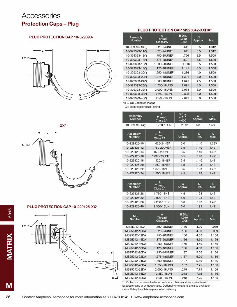
PLUG PROTECTION CAP 10-329393-
XX*
PLUG PROTECTION CAP 10-229125-XX*
PLUG PROTECTION CAP MS25042-XXDA*
Assembly Number
A Thread
Class 2A
B Dia. +.010 –.000
C Approx.
L Max.
10-329393-10 (*) .625-24UNEF .641 3 .5 1 .312
10-329393-11(*) .625-24UNEF .641 3 .5 1 .312
10-329393-12(*) .750-20UNEF .766 3 .5 1 .500
10-329393-14(*) .875-20UNEF .891 3 .5 1 .500
10-329393-16(*) 1 .000-20UNEF 1 .016 3 .5 1 .500
10-329393-18(*) 1 .125-18UNEF 1 .141 3 .5 1 .500
10-329393-20(*) 1 .250-18UNEF 1 .266 4 .0 1 .500
10-329393-22(*) 1 .375-18UNEF 1 .391 4 .0 1 .500
10-329393-24(*) 1 .500-18UNEF 1 .641 4 .5 1 .500
10-329393-28(*) 1 .750-18UNS 1 .891 4 .5 1 .500
10-329393-32(*) 2 .000-18UNS 2 .078 5 .0 1 .500
10-329393-36(*) 2 .250-16UN 2 .328 5 .0 1 .500
10-329393-40(*) 2 .500-16UN 2 .641 5 .0 1 .500
Assembly Number
A Thread
Class 2A
B Dia. +.010 –.000
C Approx.
L Max.
10-329393-44(*) 2 .750-16UN 2 .891 6 .0 1 .500
Assembly Number
A Thread
Class 2A
C Approx.
D Ref.
L Max.
10-229125-10 .625-24NEF 3 .0 .140 1 .233
10-229125-12 .750-20UNEF 3 .5 .140 1 .421
10-229125-14 .875-20UNEF 3 .5 .140 1 .421
10-229125-16 1 .000-20UNEF 3 .5 .140 1 .421
10-229125-18 1 .125-18NEF 3 .5 .140 1 .421
10-229125-20 1 .250-18NEF 3 .5 .193 1 .421
10-229125-22 1 .375-18NEF 3 .5 .193 1 .421
10-229125-24 1 .500-18NEF 4 .5 .193 1 .421
Assembly Number
A Thread
Class 2A
C Approx.
D Ref.
L Max.
10-229125-28 1 .750-18NS 4 .5 .193 1 .421
10-229125-32 2 .000-18NS 5 .0 .193 1 .421
10-229125-36 2 .250-16UN 5 .0 .193 1 .421
10-229125-40 2 .500-16UN 5 .0 .193 1 .421
MS Number
A Thread
Class 2A
B Dia. +.010 –.005
C Approx.
L Max.
MS25042-8DA .500-28UNEF .156 4 .00 .969
MS25042-10DA .625-24UNEF .156 4 .00 .969
MS25042-12DA .750-20UNEF .156 4 .50 1 .156
MS25042-14DA .875-20UNEF .156 4 .50 1 .156
MS25042-16DA 1 .000-20UNEF .156 4 .50 1 .156
MS25042-18DA 1 .125-18UNEF .156 4 .50 1 .156
MS25042-20DA 1 .250-18UNEF .187 5 .00 1 .156
MS25042-22DA 1 .375-18UNEF .187 5 .00 1 .156
MS25042-24DA 1 .500-18UNEF .187 5 .50 1 .156
MS25042-28DA 1 .750-18UNS .187 7 .75 1 .156
MS25042-32DA 2 .000-18UNS .218 7 .75 1 .156
MS25042-36DA 2 .250-16UN .218 7 .75 1 .156
MS25042-40DA 2 .500-16UN .218 7 .75 1 .156* Protective caps are illustrated with sash chains and are available with beaded chains or without chains . Optional terminations are also available . Consult Amphenol Aerospace when ordering .
AccessoriesProtection Caps – Plug
* 3 = OD Cadmium Plating G = Electroless Nickel Plating

Contact Amphenol Aerospace for more information at 800-678-0141 • www.amphenol-aerospace.com
50
15
MA
TR
IX
M27
A THD
L
D
C
B
A THD
B
C
D
L
B
D
A THD
L
C
RECEPTACLE PROTECTION CAP 10-329394-XX*
RECEPTACLE PROTECTION CAP 10-422905-
XXX*
RECEPTACLE PROTECTION CAP MS25043-XXDA*
Assembly Number
A Thread
Class 2B
B Dia. Min.
C Approx.
D Dia. Max.
L Max.
10-329394-10 .625-24UNEF .641 3 .5 .875 .793
10-329394-12 .750-20UNEF .766 3 .5 1 .000 .793
10-329394-14 .875-20UNEF .891 3 .5 1 .125 .793
10-329394-16 1 .000-20UNEF 1 .016 3 .5 1 .250 .793
10-329394-18 1 .125-18UNEF 1 .094 3 .5 1 .375 1 .024
10-329394-20 1 .250-18UNEF 1 .203 4 .0 1 .500 1 .024
10-329394-22 1 .375-18UNEF 1 .343 4 .0 1 .625 1 .024
10-329394-24 1 .500-18UNEF 1 .453 4 .5 1 .750 1 .024
10-329394-28 1 .750-18UNS 1 .766 4 .5 2 .000 1 .024
10-329394-32 2 .000-18UNS 2 .016 5 .0 2 .250 1 .024
10-329394-36 2 .250-16UN 2 .266 5 .0 2 .500 1 .024
10-329394-40 2 .500-16UN 2 .516 5 .0 2 .656 1 .024
10-329394-44 2 .750-16UN 2 .766 6 .0 2 .938 1 .024
Assembly Number
A Thread
Class 2B
B Ref.
C Approx.
D Dia. Max.
L Max.
10-422905-103 .625-24UNEF .140 3 .0 .875 .812
10-422905-123 .750-20UNEF .140 3 .5 1 .000 .812
10-422905-143 .875-20UNEF .140 3 .5 1 .125 .812
10-422905-163 1 .000-20UNEF .140 3 .5 1 .250 .812
10-422905-183 1 .125-18UNEF .193 3 .5 1 .375 1 .031
10-422905-203 1 .250-18UNEF .193 4 .0 1 .500 1 .031
10-422905-223 1 .375-18UNEF .193 4 .0 1 .625 1 .031
10-422905-243 1 .500-18UNEF .193 4 .5 1 .750 1 .031
10-422905-283 1 .750-18UNS .193 4 .5 2 .000 1 .031
10-422905-323 2 .000-18UNS .193 5 .0 2 .250 1 .031
Assembly Number
A Thread
Class 2B
B Ref.
C Approx.
D Dia. Max.
L Max.
10-422905-363 2 .250-16UN .193 5 .0 2 .500 1 .031
10-422905-403 2 .500-16UN .193 5 .0 2 .656 1 .031
MS Number
A Thread
Class 2B
B +.010 –.005
C Approx.
D Dia. Max.
L Max.
MS25043-8DA .500-28UNEF .140 4 .00 .688 .750
MS25043-10DA .625-24UNEF .140 4 .00 .815 .750
MS25043-12DA .750-20UNEF .140 4 .50 1 .000 .750
MS25043-14DA .875-20UNEF .140 4 .50 1 .125 .750
MS25043-16DA 1 .000-20UNEF .140 4 .50 1 .188 .750
MS25043-18DA 1 .125-18UNEF .140 4 .50 1 .344 .750
MS25043-20DA 1 .250-18UNEF .140 5 .00 1 .469 .750
MS25043-22DA 1 .375-18UNEF .140 5 .00 1 .594 .750
MS25043-24DA 1 .500-18UNEF .171 5 .50 1 .719 .750
MS25043-28DA 1 .750-18UNS .171 7 .75 1 .969 .812
MS25043-32DA 2 .000-18UNS .187 7 .75 2 .219 .812
MS25043-36DA 2 .250-16UN .187 7 .75 2 .469 .812
MS25043-40DA 2 .500-16UN .187 7 .75 2 .719 .812* Protective caps are illustrated with sash chains and are available with beaded chains or without chains . Optional terminations are also available . Consult Amphenol Aerospace when ordering .
MIL-DTL-5015 AccessoriesProtection Caps – Receptacle
Contact Amphenol Aerospace for more information at 800-678-0141 • www.amphenol-aerospace.com
50
15
MA
TR
IX
M28
L
B
2
L
A
C1
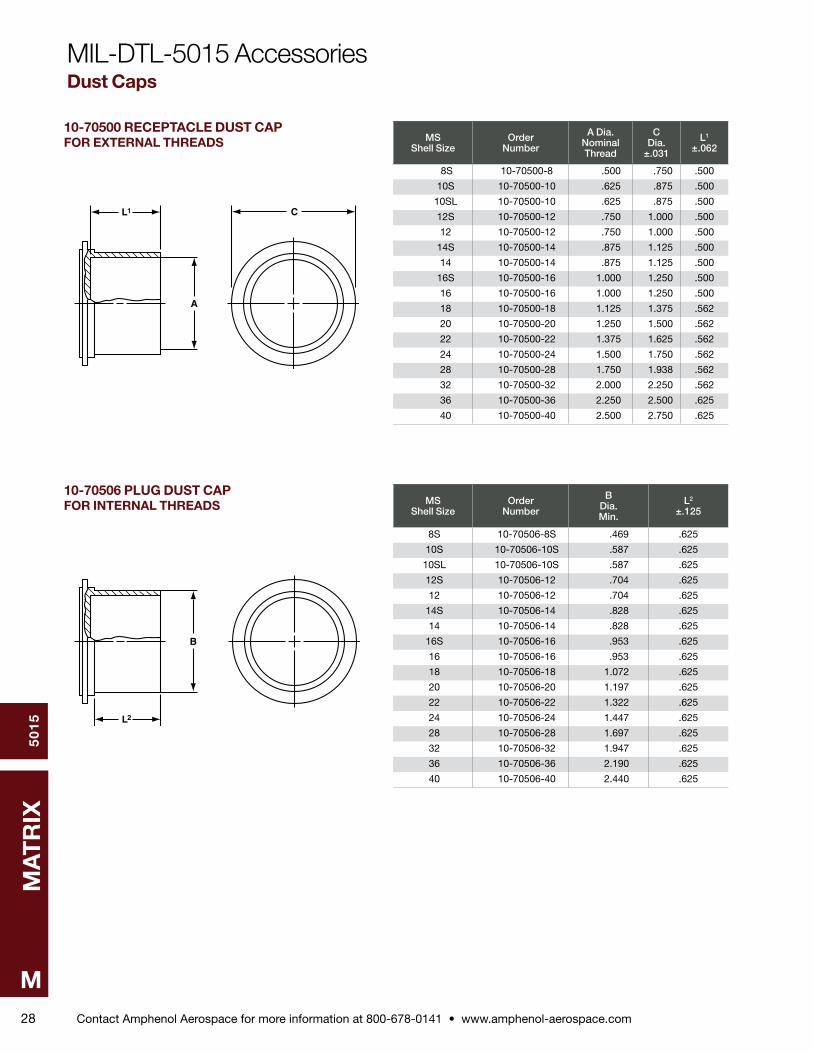
10-70500 RECEPTACLE DUST CAPFOR EXTERNAL THREADS
10-70506 PLUG DUST CAPFOR INTERNAL THREADS
MS Shell Size
Order Number
A Dia. Nominal Thread
C Dia.
±.031
L1
±.062
8S 10-70500-8 .500 .750 .500
10S 10-70500-10 .625 .875 .500
10SL 10-70500-10 .625 .875 .500
12S 10-70500-12 .750 1 .000 .500
12 10-70500-12 .750 1 .000 .500
14S 10-70500-14 .875 1 .125 .500
14 10-70500-14 .875 1 .125 .500
16S 10-70500-16 1 .000 1 .250 .500
16 10-70500-16 1 .000 1 .250 .500
18 10-70500-18 1 .125 1 .375 .562
20 10-70500-20 1 .250 1 .500 .562
22 10-70500-22 1 .375 1 .625 .562
24 10-70500-24 1 .500 1 .750 .562
28 10-70500-28 1 .750 1 .938 .562
32 10-70500-32 2 .000 2 .250 .562
36 10-70500-36 2 .250 2 .500 .625
40 10-70500-40 2 .500 2 .750 .625
MS Shell Size
Order Number
B Dia. Min.
L2
±.125
8S 10-70506-8S .469 .625
10S 10-70506-10S .587 .625
10SL 10-70506-10S .587 .625
12S 10-70506-12 .704 .625
12 10-70506-12 .704 .625
14S 10-70506-14 .828 .625
14 10-70506-14 .828 .625
16S 10-70506-16 .953 .625
16 10-70506-16 .953 .625
18 10-70506-18 1 .072 .625
20 10-70506-20 1 .197 .625
22 10-70506-22 1 .322 .625
24 10-70506-24 1 .447 .625
28 10-70506-28 1 .697 .625
32 10-70506-32 1 .947 .625
36 10-70506-36 2 .190 .625
40 10-70506-40 2 .440 .625
MIL-DTL-5015 AccessoriesDust Caps
Contact Amphenol Aerospace for more information at 800-678-0141 • www.amphenol-aerospace.com
50
15
MA
TR
IX
M29
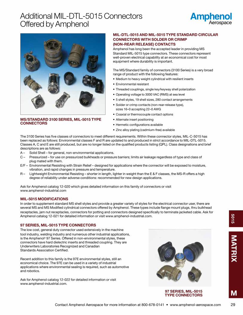
MIL-DTL-5015 AND MIL-5015 TYPE STANDARD CIRCULAR CON NECTORS WITH SOLDER OR CRIMP (NON-REAR RELEASE) CONTACTSAmphenol has long been the accepted leader in providing MS Stan dard MIL-5015 type connectors . These connectors represent well-proven electrical capability at an economical cost for most equipment where durability is important .
The MS/Standard family of connectors (3100 Series) is a very broad range of product with the following features:• Medium to heavy weight cylindrical with resilient inserts
• Environmental resistant
• Threaded couplings, single key/keyway shell polarization
• Operating voltage to 3000 VAC (RMS) at sea level
• 5 shell styles, 19 shell sizes, 280 contact arrangements
• Solder or crimp contacts (non-rear-release type), sizes 16–0 accepting 22–0 AWG
• Coaxial or thermocouple contact options
• Alternate insert positioning
• Hermetic configurations available
• Zinc alloy plating (cadmium-free) available
The 3100 Series has five classes of connectors to meet different requirements . Within these connector styles, MIL-C-5015 has been replaced as follows: Environmental classes F and R are updated to and produced in strict accordance to MIL-DTL-5015 . Classes A, C and E are still produced, but are no longer listed on the qualified products listing (QPL) . Class designations and brief descriptions are as follows:A – Solid Shell – for general, non-environmental applications .C – Pressurized – for use on pressurized bulkheads or pressure barriers; limits air leakage regardless of type and class of plug mated with them .E/F – Environmental Resisting with Strain Relief – designed for applications where the connector will be exposed to mois ture, vibration, and rapid changes in pressure and temperature .R – Lightweight Environmental Resisting – shorter in length, lighter in weight than the E & F classes, the MS-R offers a high degree of reliability under adverse conditions: recommended for new design applications .
Ask for Amphenol catalog 12-020 which gives detailed information on this family of connectors or visit www .amphenol-industrial .com
MIL-5015 MODIFICATIONSIn order to supplement standard MS shell styles and provide a greater variety of styles for the electrical connector user, there are several MS and MS Modified cylindrical connectors offered by Amphenol . These types include flange mount plugs, thru bulkhead receptacles, jam nut receptacles, connectors for potting and connectors designed specifically to terminate jacketed cable . Ask for Amphenol catalog 12-021 for detailed information or visit www .amphenol-industrial .com .
97 SERIES, MIL-5015 TYPE CONNECTORSThe low cost, general duty connector used extensively in the machine tool industry, welding industry and numerous other industrial applications, is the Amphenol® 97 Series . Offered in non-environmental styles, these con nectors have hard dielectric inserts and threaded coupling . They are Underwriters Laboratories Recognized and Canadian Standards Associa tion Certified .
Recent addition to this family is the 97E environmental styles, still an eco nomical choice . The 97E can be used in a variety of industrial applications where environmental sealing is required, such as automotive and robotics .
Ask for Amphenol catalog 12-022 for detailed information or visit www .amphenol-industrial .com .
Additional MIL-DTL-5015 ConnectorsOffered by Amphenol
97 SERIES, MIL-5015 TYPE CONNECTORS
MS/STANDARD 3100 SERIES, MIL-5015 TYPE CONNECTORS
