170 cover 9/21/98 9:31 am page 1 gpscom 170 -...
TRANSCRIPT

G P S C O M
1 7 0
O w n e r ’ sM a n u a l &R e f e r e n c e
170 cover 9/21/98 9:31 AM Page 1
Software Version 2.02 or above
© 1997 GARMIN Corporation1200 E. 151st Street, Olathe, KS USA 66062Tel: 913-397-8200 or 800-800-1020Fax: 913-397-8282Web Site Address: www.garmin.com
GARMIN (Europe) LTDUnit 5, The Quadrangle, Abbey Park Industrial Estate, Romsey, U.K. SO51 9AQTel: 011-44-1794-519944Fax: 011-44-1794-519222
All rights reserved. No part of this manual may be reproduced or transmitted inany form or by any means, electronic or manual, including photocopying andrecording, for any purpose without the expressed written permission ofGARMIN.
Information in this document is subject to change without notice. GARMINreserves the right to change or improve its products and to make changes in thecontent without obligation to notify any person or organization of such changesor improvements.
GARMIN, AutoLocate, AutoStore, AutoZoom, GPSCOM, PhaseTrac12, andTracBack are all trademarks of GARMIN Corporation and may not be used with-out its expressed permission.
April 1997 Part #190-00093-00 Rev. D Printed in USA.
i
170 manual pages rev D 9/21/98 9:23 AM Page i

IMPORTANT!
The Telecommunications Act of 1996, effective February 8, 1996, provides the FCC discretionto eliminate radio station license requirements for aircraft and ships. At the present time, youdo not need an individual license to operate the GPSCOM 170 aboard your private vessel inmany circumstances. To find out the specific details on whether you are exempt from licens-ing, please see FCC Fact Sheet PR 5000 or contact the FCC at 1-800-322-1117.
Note that no license is required for a portable radio used only as a backup on a vessel whichalready has a station license per FCC 506 Instructions dated 1993.
If a marine license is required or desired, contact the FCC at 1-800-322-1117 to request form506, Application for Ship Radio Station License.
The FCC also has a fax-on-demand service to provide forms by fax at 1-202-418-0177.
The GPSCOM 170 owner accepts all responsibility for obtaining the proper licensing beforeusing the transmitter.
ii
WARNING! This transmitter will operate on channels/frequen-cies that have restricted use in the United States. The channelassignments include frequencies assigned for exclusive use of theU.S. Coast Guard, use in Canada, and use in Internationalwaters. Operation in these frequencies without proper autho-rization is strictly forbidden. For frequencies/channels that arecurrently available for use in the U.S. without an individuallicense, please contact the FCC Call Center at 1-888-CALL-FCC.
170 manual pages rev D 9/21/98 9:23 AM Page ii

Before getting started, check to see that your GARMIN GPSCOM 170package includes the following items. If you are missing any parts, please contact your dealer immediately.
GPSCOM 170OWNER’S MANUAL
• GPSCOM 170 Unit
• Flex Whip Com Antenna
• Quick Reference Card
• Owner’s Manual
• Trickle Charger/AC Adapter
• Belt Clip
• Carrying Case
• Wrist Strap
Packing List
INTRODUCTION
iii
170 manual pages rev D 9/21/98 9:23 AM Page iii

CAUTION
Cautions
INTRODUCTION
The GPS system is operated by the government of the United States, which issolely responsible for its accuracy and maintenance. The system is subject tochanges which could affect the accuracy and performance of all GPS equipment.Although the GPSCOM 170 is a precision electronic NAVigation AID (NAVAID),any NAVAID can be misused or misinterpreted and therefore, become unsafe.
Use the GPSCOM 170 at your own risk. To reduce the risk of unsafe opera-tion, carefully review and understand all aspects of this Owner’s Manual andthoroughly practice operation using the simulator mode prior to actual use.When in actual use, carefully compare indications from the GPSCOM 170 to allavailable navigation sources including the information from other NAVAIDs,visual sightings, charts, etc. For safety, always resolve any discrepancies beforecontinuing navigation.
NOTE: This device meets requirements for Part 15 of the FCC limits for Class Bdigital devices for home or office use. It has been tested for compliance with allnecessary FCC standards. This equipment generates, uses, and can radiate radiofrequency energy and, if not installed and used in accordance with the instruc-tions, may cause harmful interference to radio communications. However, thereis no guarantee that interference will not occur in a particular installation. If thisequipment does cause harmful interference to other equipment, which can bedetermined by turning the equipment off and on, the user is encouraged to tryand correct the interference by relocating the equipment or connecting theequipment to a different circuit than the affected equipment. Consult an autho-rized dealer or other qualified service technician for additional help if theseremedies do not correct the problem. Operation is subject to the following con-ditions: (1) This device cannot cause harmful interference, and (2) this devicemust accept any interference received, including interference that may causeundesired operation. The GPSCOM 170 does not contain any user-serviceableparts. Repairs should only be made by an authorized service center.Unauthorized repairs or modifications could void your warranty and yourauthority to operate this device under Part 15 regulations.
iv
170 manual pages rev D 9/21/98 9:23 AM Page iv

SECTION ONE Introduction
Unit Description/Keys and Controls . . . . . . . . . . . . . . . . . . . . . . . . .2-3Keys and Controls . . . . . . . . . . . . . . . . . . . . . . . . . . . . . . . . . . . . . .4-5
SECTION TWO Getting Started
Acquiring Satellites . . . . . . . . . . . . . . . . . . . . . . . . . . . . . . . . . . . . . . .6Navigation Pages . . . . . . . . . . . . . . . . . . . . . . . . . . . . . . . . . . . . . .7-13VHF Transceiver Basics . . . . . . . . . . . . . . . . . . . . . . . . . . . . . . . . .14-17
SECTION THREE Reference
Satellite Status and Position Pages . . . . . . . . . . . . . . . . . . . . . . . . .18-21Creating, Using, and Editing Waypoints . . . . . . . . . . . . . . . . . . . .22-28Using the VHF Transceiver . . . . . . . . . . . . . . . . . . . . . . . . . . . . . .29-38GOTO, MOB, and TracBack Navigation . . . . . . . . . . . . . . . . . . . . .39-41Route Navigation . . . . . . . . . . . . . . . . . . . . . . . . . . . . . . . . . . . . .42-47Navigation Guidance Pages . . . . . . . . . . . . . . . . . . . . . . . . . . . . . .48-55Menu Page . . . . . . . . . . . . . . . . . . . . . . . . . . . . . . . . . . . . . . . . . . . .56System Setup . . . . . . . . . . . . . . . . . . . . . . . . . . . . . . . . . . . . . . . .57-63Appendix A—Initializing the Receiver . . . . . . . . . . . . . . . . . . . . . .64-66Appendix B—Accessories and Installation . . . . . . . . . . . . . . . . . . .67-69Appendix C—VHF Channel List . . . . . . . . . . . . . . . . . . . . . . . . . .70-71Appendix D—Specifications . . . . . . . . . . . . . . . . . . . . . . . . . . . . .72-73Appendix E—Messages . . . . . . . . . . . . . . . . . . . . . . . . . . . . . . . . .74-75Appendix F—Map Datums . . . . . . . . . . . . . . . . . . . . . . . . . . . . . .76-77Appendix G—Time Offset Chart . . . . . . . . . . . . . . . . . . . . . . . . . . . .78Appendix H—Index . . . . . . . . . . . . . . . . . . . . . . . . . . . . . . . . . . .79-81
Table OfContents
INTRODUCTION
1
170 manual pages rev D 9/21/98 9:23 AM Page 1

Speaker Arrow Keypad
Microphone
ChannelSelection Arrow
Keys
Map ScaleZoom Keys
Flex Com Antenna
LCD Display
The GPSCOM 170 combines a 12 paral-lel channel GPS receiver with a 5 wattmarine VHF communications transceiver ina convenient handheld package. A keypadlocated on the front of the unit providescontrol of the navigation and communica-tion functions. The 16/9 key allows for onebutton selection of channel 16 or 9. Knobsfor controlling squelch, power and volumeare located on top of the unit. The micro-phone is located in the lower left speakerarea.
Front View
Internal GPSAntenna
SquelchControl
VolumeControl
BNC AntennaConnector
Top View
UnitDescription
introduction
2
170 manual pages rev D 9/21/98 9:23 AM Page 2

External GPS Antenna Connector
Power/Data/ExtSpk/Ext Mic
CableConnectorPTT Switch
BacklightButton
Transmit PowerButton
Charger/AC Adapter Connector
H/L
The backlight button, transmitting power/override button, charger/AC adapter connec-tor, and push-to-talk (PTT) switch are located on the left side of the unit. The connector forthe external GPS antenna and power/data/ext speaker/ext mic cable are located on the rightside. A removable Ni-Cad battery pack powers the unit and attaches to the back. SeeAppendix B for instructions on installing and removing the battery pack.
Side Views
Removable Battery Pack
UnitDescription
introduction
3
H/L
170 manual pages rev D 9/21/98 9:23 AM Page 3

KUse the two-speed ARROW KEYPAD to enter data. Press on a particulararrow key once to scroll through data options slowly. Press and hold down anarrow key for faster scrolling.
Use the UP and DOWN arrow keys to select alphanumerical characters andmenu choices, and to move the field highlight from field to field.
The MOB key performs the man overboard function. This marks the currentposition, and always displays your current range and bearing from this posi-tion.
The MARK key captures a position and displays the mark position page.
The QUIT key returns you to a previous page, or clears data entry and restoresa data field’s previous value.
K
The PAGE key scrolls through the main data pages in sequence and returns thedisplay from a submenu page to a main page. It also displays the messagescreen when a message alert appears.
The GOTO key displays the GOTO waypoint page, allowing you to select the destination waypoint.
B
Use the LEFT and RIGHT arrow keys to move the selected character field, andto move the highlight from field to field. The left arrow key is also used to cleara selected field.
U
D
L R
EThe ENTER key confirms data entry and on-screen responses. This key alsoactivates highlighted fields to allow data entry.
Keys andControls
introduction
4
G
U
D
ZOOMThe MAP SCALE ZOOM keys select the desired map range from 0.2 to 320nm.
P
Q
170 manual pages rev D 9/21/98 9:23 AM Page 4

The WX/CH key places the unit in weather channel receive mode.
The SCAN key puts the unit into the “all scan” or the “memory scan” mode.
W
S
The ON/OFF/VOLUME control turns the unit on and off and adjusts the volumelevel.
The GPSCOM key lets you choose between the main GPS and main communicationpages.
The PUSH-TO-TALK (PTT) switch activates the GPSCOM 170 transmitter on theactive frequency.
The SQUELCH control eliminates receiver background noise and allows only receivedtransmissions to be heard.
The BACKLIGHT button illuminates the arrow keypad and LCD Screen through fourlevels of backlighting (three levels of brightness and off).
C
Keys andControls
introduction
5
T The DUAL/TRI key activates dual and tri watch monitoring.
N The 16/9 key selects channel 16 or 9 for immediate use.
MThe MEM key accesses the memory setup page which enables you to program channels into memory.
U
D
CHAN
The CHANNEL SELECTION arrow keys are used to select channels. The channelnumber can be increased or decreased one with each press, or if held will continue toincrease or decrease the number as long as the key is held.
H/L The TRANSMIT POWER BUTTON selects one or five watts of transmit power.
170 manual pages rev D 9/21/98 9:23 AM Page 5

Getting Started
The GPSCOM 170 is a powerful navigation and com-munication tool that offers mariners a host of advancedfeatures that help make boating safer and more efficient.The getting started tour is designed to quickly guide youthrough basic features and functions of the unit. Onceyou’ve completed the tour and become familiar with themain pages and features of the unit, refer to the referencesection for complete instructions on performing specifictasks and functions.
The getting started tour assumes you have initializedthe unit according to the instructions given in AppendixA, and have not changed any of the default settings. Ifyou have changed any settings, the descriptions and pic-tures used may not match your configuration.
Powering Up
To turn the GPSCOM 170 on:
1. Turn the VOL control clockwise.
The welcome page will be displayed while the unitconducts a self test. Once testing is complete, the wel-come page will be replaced by the satellite status pageand the GPSCOM 170 will begin acquiring satellite data.
Satellite Status Page
The satellite status page provides a visual reference ofsatellite acquisition and receiver status, with a signalstrength bar graph and a satellite sky view in the centerof the page. The accuracy of your position is shown in theupper right hand side of the page.
The satellite sky view and signal strength bars giveyou an indication of what satellites are visible to thereceiver and whether they are being tracked. Satellites,labeled with numbers and letters, are placed on the pageindicating their position in the sky.
The signal strength bars show how strong the signalis from each satellite being tracked: The taller the bar, thestronger the signal. For more information on the satellitestatus page, see page 18.
You’ll know you have a fix when a 2D or 3D statusappears in the status field or the receiver automaticallytransitions to the position page. If you encounter difficul-ty acquiring satellite signals, see Appendix A.
Important!
Make sure you charge the Ni-Cad battery pack for 14hours before using yourGPSCOM 170 to ensureoptimum capacity and per-formance. Note: Whencharging the battery pack,turn the unit off to ensure afull charge. Completeinstructions on charging thepack are in Appendix B.
The signal strength bars onthe satellite status page giveyou an indication of whatsatellites are visible to thereceiver, whether or notthey’re being used to calcu-late a position fix, and thesignal quality.
Acquiring Satellites
GettingStarted
6
170 manual pages rev D 9/21/98 9:23 AM Page 6

Position Page
The position page shows where you are, what direc-tion you’re heading and how fast you’re going. Thegraphic compass at the top of the page indicates thedirection you’re moving. The four user-selectable datafields below the compass tape show your current courseand speed over ground, along with a resettable tripodometer and altitude display. Your current latitude andlongitude, along with a 12/24-hour clock, appear at thebottom of the page.
The VHF status field appears at the bottom of everypage. It displays (from left to right) the current channel,band of operation, operating mode, and output powerlevel. The VHF status field elements are discussed indetail in the reference section.
The graphic compass display is designed to show your cur-rent track and does not serve as a true magnetic compasswhile you’re standing still.
Position Page
GettingStarted
7
GraphicCompass
Tape
Current Track
Time of Day
Speed Over Ground
Position Coordinates
Altitude
VHF Status Field
!#
The position page also fea-tures a resettable tripodometer to keep track ofyour distance traveled.
In addition to displayingyour position coordinates,the position page showsyour track and speed overthe ground.
170 manual pages rev D 9/21/98 9:23 AM Page 7

Marking a Position
Now that you’ve acquired a position, let’s mark it as awaypoint for future reference.
1. Press the K key to capture and hold your posi-tion.
To mark a position, you must have obtained a 2D or 3Dfix, or have the receiver in simulator mode. If you try tomark a position without a position fix, you will be alertedwith a ‘No Position’ message.
The mark position page will appear, showing the cap-tured position and a default 3-digit waypoint name, 001.Let’s change the name to something more meaningful,like ‘HOME’.
1. Use the arrow keypad to move the field highlight fromthe ‘SAVE?’ field to the ‘Waypoint’ field.
2. Press E and the left arrow key to clear thedefault waypoint name.
3. Press and hold the up arrow key to scroll through thealphabet until the letter ‘H’ appears.
4. Press the right arrow key once to move the characterhighlight to the next character space.
5. Repeat steps 3 and 4 until the word ‘HOME’ is displayed.
6. Press E to complete entry of the name.
7. Press the down arrow key once to return the field high-light to the ‘SAVE’ field.
8. Press E to confirm that you want to save the posi-tion as a waypoint named ‘HOME’.
The mark position page will now be replaced by theposition page (the page displayed prior to pressingMARK. The ‘HOME’ waypoint is now stored in theGPSCOM 170’s memory, and will remain there until youmanually remove it or clear the receiver’s memory. Formore on waypoint management, see pages 22-28.
To save a waypoint with thethree digit name, simplypress ENTER on ‘SAVE’.
Marking aPosition
GettingStarted
8
!#
The arrow keypad is usedfor all data entry. Use theUP and DOWN keys toselect letters, numbers, ormenu options; use the LEFTand RIGHT keys to movethe cursor forward or back-ward along the line.
170 manual pages rev D 9/21/98 9:23 AM Page 8

Using the Position and Map Pages
Now that you’ve marked a position, it’s time to take abrisk walk using the position and moving map pages towatch your every move. You will need to walk for at leastthe time stated in the below steps.to get a much betterindication of how the GPSCOM 170’s steering guidanceand mapping features work.
1. Walk in a straight line for 3-4 minutes at a fast pace andwatch the position page. You can time your distancewith the on-screen clock.
The direction you are moving (your track) and yourspeed are displayed on the upper part of the screen, justbelow the graphic compass display. The latitude, longi-tude and approximate altitude of your position–alongwith a resettable trip odometer–are continuously dis-played in the middle of the page, with the time of day dis-played below.
Now let’s change the display to the moving map pageand watch the track log of our walk:
1. Press the P key to change from the position pageto the map page.
Position andMap Pages
GettingStarted
9
Map Page
The map page displays yourpresent position as a dia-mond icon and provides areal time graphic ‘bread-crumb’ display of your trackright on screen.
The moving map’s defaultsetting is track up orienta-tion. ‘Track up’ means thatyour current direction oftravel is always up (ortowards the top of) thescreen. It can also be set fornorth up, or desired track uporientation by using the mapsetup page.
170 manual pages rev D 9/21/98 9:23 AM Page 9

Moving Map Pages
The GPSCOM 170’s next page, the moving map page,shows your movement as a track log, with your presentposition shown as a diamond icon in the center of themap. You’ll notice the black square below the diamond,which represents the position you just created (‘HOME’),and the line between the two, which shows your track.
Nearby waypoints are represented as squares, withthe waypoint name listed above the square. When youwant to change the map scale, simply use the up anddown arrow zoom keys to select the desired scale.
1. Now turn 90º to your right and continue walking at afast pace for another 2-3 minutes. Notice how the dis-play changes, always keeping the direction you aremoving at the top of the map.
Going To a Waypoint
Once you’ve stored a waypoint in memory, you canuse the GPSCOM 170 to guide you to it by performing asimple GOTO. A GOTO is really nothing more than thereceiver drawing a straight-line course from your presentposition to the destination you’ve selected. To see how itworks, let’s try navigating back to our starting position,the HOME waypoint.
To select a GOTO destination:
1. Press G.
2. The G waypoint page will appear, displaying allthe waypoints in memory in alphabetical order.
3. Use the arrow keypad to highlight the ‘HOME’ waypoint.
4. Press E to confirm that you want to navigate tothe displayed waypoint.
The GOTO waypoint pageallows you to select yourdestination from a list of allavailable waypoints in theGPSCOM 170’s memory.
Moving MapPage
GettingStarted
10
When you want to changethe map scale, simply usethe up and down arrowzoom keys to select thedesired scale.
170 manual pages rev D 9/21/98 9:23 AM Page 10

Using the Highway Page
The GPSCOM 170’s highway page provides graphicsteering guidance to a destination, with an emphasis on astraight–line course to the desired waypoint and the dis-tance and direction you are off course. The bearing anddistance to a waypoint, along with your current track andspeed, are displayed at the top of the screen, with yourestimated time enroute (ETE) and velocity made good(VMG), or the rate you are closing in on your destination,shown at the bottom.
As you head toward your destination, the middle sec-tion of the screen provides visual guidance to your way-point on a moving graphic ‘highway’. The moving arrowjust below the course deviation scale always points toyour selected waypoint relative to the direction you aremoving.
Your present position is represented by the diamondin the center of the course deviation scale. The line downthe middle of the highway represents your desired track.As you navigate toward a waypoint, the highway willactually move, indicating the direction you’re off course,relative to the position square on the CDI scale. To stayon course simply steer toward the center of the highway.
As you approach a way-point, a horizontal ‘finishline’ will move toward thebottom of the highway.
Your present position is rep-resented by the square inthe center of the coursedeviation scale.
Using TheHighway Page
GettingStarted
11
Distance toWaypoint
Track OverGround
Bearing toWaypoint
Estimated Time Enroute
Velocity Made Good
Speed OverGround
GraphicHighway
CourseDeviation
Scale
Pointer to selectedwaypoint
170 manual pages rev D 9/21/98 9:23 AM Page 11

If you do get off course by more than 1/5th of theselected CDI range, the exact distance you are off coursewill be displayed where the CDI scale normally appears.As you approach a waypoint, a horizontal ‘finish line’ willmove toward the bottom of the highway. When the finishline reaches the CDI scale, you’ve arrived at your desti-nation. Whenever the unit has something it needs to tellyou, a message indicator will flash on screen. When youare less than one minute from reaching your HOME way-point, the message box will begin flashing.
1. To view a message, press P when the messageindicator appears.
2. Press P to return to the previous page.
There’s also a compass page to helps provide bettersteering guidance where straight–line navigation is notpossible.
To select the compass page:
1. While viewing the highway page, press E twice.
The compass page will now become the displayednavigation page. This page provides a directional pointerto your destination by using a rotating compass display toshow direction of travel. It provides better steering guid-ance at slower speeds for travel with many directionalchanges.
To switch back to the highway page:
1. Press E twice.
Compass Page
The GPSCOM 170 will alsoprovide steering guidancewith a graphic compass.
Compass &Message Page
GettingStarted
12
Message Page
Once you are one minutefrom the destination, anarrival message will appearon the message page.
170 manual pages rev D 9/21/98 9:23 AM Page 12

GPS Page Sequence
Now that you’ve arrived ‘HOME’, let’s take a minute tosee how the GPSCOM 170’s main GPS pages worktogether. The unit features five main pages, which arelinked together in a chain. You can quickly scroll throughthe pages in either direction using the P and Qkeys.
1. Press P to scroll through the five main pages insequence.
2. Press Q to scroll through pages in the oppositedirection.
Menu Page
You’ve already seen the first four pages in action byacquiring satellites, marking a position and navigating toa destination. The last page available from the main GPSpage sequence is the menu page, which provides accessto the GPSCOM 170’s waypoint management, route,track log and setup features. The 11 submenus are divid-ed into categories by function.
To select a submenu from the menu page:
1. Press Por Q until the menu page appears.
2. Use the arrow keypad to highlight the submenu youwant to view.
3. Press E to access the submenu.
You’ve now gone through the basic operation of thenavigation portion of your new GPSCOM 170. Now let’smove on to using the VHF radio.
Use the arrow keypad toselect a submenu from themenu page. Press ENTERto access the selected sub-menu.
GPS PageSequence
GettingStarted
13
Highway Page Menu PagePosition PageSatellite Page Map Page
170 manual pages rev D 9/21/98 9:23 AM Page 13

Using the VHF Transceiver
The first step in using the VHF transceiver is to makesure the volume and squelch controls are set correctly forproper reception.
1. Turn the VOL control clockwise to turn the unit on.
2. Rotate the SQL control fully counterclockwise. Thisstate is known as “squelch off”. Increase the volumeto achieve a comfortable listening level.
3. Slowly turn the SQL control clockwise and stop slightlypast the point where the noise disappears. This condi-tion is known as the “squelch threshold”.
If the knob is turned past this point, weak signalsmay not be received. No noise and no signals are receiveduntil a signal with sufficient strength is received thatexceeds the squelch threshold. When the GPSCOM 170is in receive mode, ‘RX’ is displayed in the VHF statusbar.
VHF Communication Pages
To move back and forth between the GPS and VHFpages, press C. There are three com VHF pages in acontinuous loop: channel definition, com setup, andmemory bank. Press C to exit the GPS pages andenter the com pages. Try scrolling through the com pagesby pressing P You can also scroll in the oppositedirection or return to a previous page by pressing Q.The function of each of the com pages is discussed indetail in the reference section.
The current channel willalways be displayed at thebottom left of every page.
Using the VHFTransceiver
GettingStarted
14
Important!
We strongly recommendobtaining a marine radiouser’s guide such as“Maritime Radio User’sHandbook” published bythe RTCM (RadioTechnical CommissionFor Maritime Services),Washington, D.C., toensure proper radio oper-ation and protocol.Improper usage can resultin fines levied onmariners by the FCC.
SquelchControl
VolumeControl
Com Setup PageChannel Page Mem Bank Page
P
Q
170 manual pages rev D 9/21/98 9:23 AM Page 14

Selecting a Channel
The GPSCOM 170 operates on all U.S., Canadian,and International Marine VHF radio channels.
To select a channel from any page:
1. Use the UP and DOWN channel selection arrow keysto select the desired channel. The channel number willincrease or decrease with each press–or if held, willcontinue to change the number as long as the key isheld. The selected channel will always be displayed atthe left hand side of VHF status bar.
Transmitting
To transmit:
1. Press the push-to-talk (PTT) button. ‘TX’ appears in theVHF status bar when the PTT button is pressed. Speakslowly and clearly into the microphone. Hold the unitabout 1/2 to 1 inch from your mouth.
2. Release the PTT button when you are finished speaking.
Tips on Transmitting
• Transmitting without an antenna connected to theGPSCOM 170 may damage the unit. See AppendixB for instructions on installing and removing theantenna. The GPSCOM 170 will not transmit usingexternal power without the battery pack. Make surethe battery pack is installed.
• If the PTT button is held in for more than 35 sec-onds, the transmitter will automatically shut off.The message ‘Stuck PTT’ will also be displayed onthe message page.
• The GPSCOM 170 gives you the option of trans-mitting using 1 watt or 5 watts of power.Transmitting at 1 watt power is a nice option so thatshort-range conversations won’t interfere with alarge number of boaters. Transmitting at 1 watt alsoprolongs battery life.
To switch between high and low power:
1. Press the transmitting power button to switch betweenlow and high power.
Important!
Certain channels are set asideto be used by authorized sta-tions for specific purposes,depending on the type of ves-sel (commercial or non-com-mercial). Full familiarizationwith channel usage is essen-tial when selecting a channel.
An ‘H’ will be displayed inthe right–hand side of theVHF status field for 5 wattoperation, and an ‘L’ for 1watt .
Transmitting
GettingStarted
15
170 manual pages rev D 9/21/98 9:23 AM Page 15

Selecting Channel 16 and 9
The GPSCOM 170’s channel 16/9 button providesquick access to channel 16 or 9.
To select channel 16:
1. Press N.
To select channel 9:
1. Press N again.
Tips on Using Channel 16 and 9
• Channel 16 is used for emergency purposes and forinitially contacting (hailing) another vessel.
• The use of channel 16 for hailing must be limitedto initial contact only. Calling should not exceed 30seconds, but may be repeated 3 times at two-minute intervals.
• In areas of heavy radio traffic, congestion on chan-nel 16 resulting from its use as a hailing channelcan be reduced significantly in U.S. waters by usingchannel 9 as the hailing channel for non-emergencycommunications.
• Before making contact with another vessel, refer tothe RTCM marine radio user’s guide to select anappropriate channel for communications after ini-tial contact.
Selecting a Weather Channel
The GPSCOM 170 receives 10 weather channels,including all 7 National Weather Service channels in andaround the U.S., and most Environment Canada WeatherRadio broadcast stations.
To select a weather channel:
1. PressW. ‘W’ will be displayed next to the selectedchannel in the VHF status bar.
2. Use the UP and DOWN channel selection arrow keysto select the desired weather channel.
3. Press W to return to regular channels.
A ‘W’ is displayed next toevery selected weatherchannel.
Channel 16 is used foremergency purposes and forinitially contacting (hailing)another vessel.
SelectingChannel 16/9
GettingStarted
16
170 manual pages rev D 9/21/98 9:23 AM Page 16

Dual Watch
Dual Watch scans between channel 16 and the lastchannel that was selected. It’s handy when you need tomonitor channel 16, but also want to listen to anotherchannel for traffic.
To start dual-watch:
1. Press T. The unit will scan between channel 16and the last selected channel, stopping on the channelthat has radio traffic. Once the radio traffic hasstopped, the unit will resume scanning. To cancel dualwatch press T twice or the PTT button once.
Congratulations! You’ve just completed the gettingstarted tour! You now know enough about the GPSCOM170 to go out and have some fun with it.
We strongly recommend that you read on andexplore the reference section, which contains a closerlook at all of the exciting features of the GPSCOM 170.
To turn the GPSCOM 170 off:
1. Turn the VOL control counterclockwise.
Thank you for choosing the GARMIN GPSCOM 170.We hope it will make your boating safer and more enjoyable.
Dual watch scans betweenchannel 16 and the lastselected channel.
Dual Watch
GettingStarted
17
170 manual pages rev D 9/21/98 9:23 AM Page 17

Satellite Status Page
The satellite status page displays the status of variousreceiver functions. The status information will help youunderstand what the GPSCOM 170 is doing at any giventime, and tell you whether or not the receiver has calcu-lated a position fix.
Sky View and Signal Strength Bars
The satellites are identified by letters and numbers.The sky view and signal strength bars give you an indica-tion of what satellites are visible to the receiver, whetheror not they are being used to calculate a position fix, andthe signal quality. The sky view in the center of the pageshows a bird’s-eye view of the position of each satelliterelative to the receiver’s last known position. The outercircle represents the horizon (north up); the inner circle45º above the horizon; and the center point a positiondirectly overhead.
When the receiver is looking for a particular satellite,the corresponding signal strength bar will be blank andthe sky view indicator will remain highlighted in reversevideo. Once the receiver has found the satellite, a hollowsignal strength bar will appear, indicating that the satel-lite has been found and the receiver is collecting datafrom it. The satellite number or letter in the sky view willalso change from reverse video to normal presentation.As soon as the GPSCOM 170 has collected the necessarydata to use the satellite for positioning, the hollow barwill become solid.
Satellites in view but notcurrently in use (Q & 9)will be displayed in reversevideo, with a corresponding‘hollow’ signal strength bar.
Satellite StatusPage
Reference
18
Once a satellite in view isusable for positioning, thesatellite number willchange from reverse videoand the signal strength barwill become solid.
Operating Mode
Signal StrengthIndicator Bars
SatelliteNumbers/Letters
Satellite SkyView
EstimatedPosition Error
Battery Voltage
170 manual pages rev D 9/21/98 9:23 AM Page 18

Receiver Status
Receiver status is indicated at the top left of thescreen, with the current horizontal accuracy (estimatedposition error, in feet or meters) at the top right. The sta-tus will show one of the following conditions:
Searching— the GPSCOM 170 is looking for anyavailable satellites in view.
AutoLocate— the GPSCOM 170 is initializing andcollecting new almanac data. This process can take 3to 5 minutes.
Acquiring— the receiver is collecting data fromavailable satellites, but has not collected enough datato calculate a 2D fix.
2D Navigation— at least three satellites with goodgeometry have been locked onto and a 2-dimension-al position fix (latitude and longitude) is being calcu-lated. ‘2D Diff’ will appear when you are receivingDGPS corrections in 2D mode.
3D Navigation— at least four satellites with goodgeometry have been locked onto, and your position isnow being calculated in latitude, longitude and alti-tude. ‘3D Diff’ will appear when you are receivingDGPS corrections in 3D mode.
Poor GPS Coverage— the receiver is no longertracking enough satellites for a 2D or 3D fix.
Not Usable— the receiver is unusable, possibly dueto incorrect initialization or abnormal satellite condi-tions. Turn the unit off and back on to reset.
Simulator— the receiver is in simulator mode.
EZinit Prompt
The satellite status page also provides access to theEZinit prompt whenever a position fix has not been cal-culated (the unit must be in searching, AutoLocate,acquiring, simulator or poor coverage mode). This allowsyou to manually reinitialize the unit (see Appendix A forinstructions), and is useful if you have travelled over 500miles with the receiver off and you know it must be ini-tialized to your new position. The GPSCOM 170 willautomatically offer the EZinit prompt after 10 minutes ofunsuccessful satellite acquisition.
If you travel more than 500miles with the receiver off,you may have to reinitializeit to your new location. Toaccess the EZinit prompt,press ENTER from the sta-tus page before the receiverhas acquired any satellites.
Receiver Status
Reference
19
A ‘Poor Coverage’ statuswill appear if the receiverhas lost the satellitesrequired to compute a fix.Make sure the internalantenna is not covered andhas a clear view of the sky.
170 manual pages rev D 9/21/98 9:23 AM Page 19

Battery Voltage Indicator
The satellite status page displays current battery voltage for the Ni-Cad battery pack. When using the Ni-Cad pack, any voltage above 7.2 indicates a fullycharged condition. You should charge the battery packwhen the voltage is between 5.8 and 7.2. At 5.8 volts,you will get a low battery voltage message. At 5.5 volts, the Com and GPS functions shutoff. It is normal to see a drop in voltage when transmitting.
The trickle charger/AC adapter supplied with theGPSCOM 170 converts line voltage to the DC voltagenecessary to operate the unit. The AC adapter also slow-ly recharges the Ni-Cad battery pack at a rate of 14 hoursfor a full recharge. Make sure you charge the Ni-Cad battery pack for 14 hours before using yourGPSCOM 170 to ensure optimum capacity and perfor-mance. When charging the battery pack, be sure to turnthe unit off to ensure a full charge.
Screen Backlighting and Contrast
If you want to see the display at night, you have toturn on the ‘backlight’ (which is a very small light bulbbehind the screen). The bulb lights the screen display fora user-defined interval (the default is 15 seconds) afterevery keystroke. There are three levels of light intensity.When backlighting is on, a bulb icon will appear in theupper right–hand corner of the display. To adjust thelength of time the backlighting will stay on, refer to system setup in the reference section.
To turn the screen backlighting on:
1. Press the backlight button. Cycle through the three lev-els of backlight by pressing the backlight button.
To turn the screen backlighting off:
1. Press the backlight button. Whenever the backlightingis off, the bulb icon disappears from the screen.
To set the screen contrast:
1. Use left and right arrow keys to adjust the bar scalefor the desired contrast and press E.
Screen contrast is adjustablefrom the satellite statuspage.
ScreenBacklighting
Reference
20
IMPORTANT!
Using the screen backlight-ing can greatly affect bat-tery life. If you’re usingyour GPSCOM 170 pri-marily in daylight hours,you should keep the back-light timeout at the default15 second setting.
170 manual pages rev D 9/21/98 9:23 AM Page 20

Position Page
The GPSCOM 170’s position page shows you whereyou are, what direction you’re heading and how fast youare going (up to 99.9 mph), and is most useful when youare travelling without an active destination waypoint. Agraphic compass tape at the top of the page displays yourcardinal heading (while you’re moving), with your cur-rent track and speed over the ground indicated below.
The rest of the page shows your present position inthree dimensions (latitude, longitude and altitude). Theunits of measure for speed, distance, position and altitudeare all user-selectable through the navigation setup menu(see page 59). The 12/24 hour clock and time offsetoptions are available from the system setup menu (see page 57).
Trip Odometer
The position page also features a resettable tripodometer to measure the total distance travelled while navigating.
To reset the trip odometer:
1. Highlight the ‘TRIP’ field.
2. Press E followed by the left arrow key.
3. Press E to finish.
Altitude Display
When the GPSCOM 170 is acquiring satellites or navigating in the 2D mode, the last known altitude willbe used to compute your position. If the altitude shownis off by several hundred feet, you can manually enteryour altitude for greater accuracy. Note that GPS altitudescan fluctuate due to errors.
To enter your altitude:
1. Highlight the ‘ALT’ field. Press E to begin entry ofyour altitude.
2. Use the arrow keypad to enter a value in each charac-ter field and to move to the next character position.
3. PressE to confirm the altitude.
Position Page
Reference
21
The speed displayed on theposition page may fluctuateat slow speeds (or whenyou’re standing still).
To reset the trip odometer,highlight the trip field andpress ENTER. Use theLEFT arrow key to clear thedistance field and pressENTER to confirm.
170 manual pages rev D 9/21/98 9:23 AM Page 21

Marking and Saving Waypoints
Knowing your present position is only part of anynavigation equation. You also need to keep track ofwhere you’ve been and where you are going. Waypointsserve as electronic markers that let you keep track ofstarting points, destinations, navaids and any otherimportant position.
The GPSCOM 170 allows you to mark, store and useup to 250 waypoints. A waypoint position can be enteredby taking an instant electronic fix or by manually enter-ing a coordinate or range and bearing in reference to anexisting waypoint. If you try to mark a waypoint withouthaving a position fix, you’ll be notified with a ‘No GPSPosition’ message.
To mark your present position:
1. Press K to capture your position.
The mark position page will appear, showing the cap-tured position and a default 3-digit waypoint name.
To change the default position name:
1. Press the up arrow key twice to move the field high-light from the ‘SAVE?’ field to the name field.
2. PressE to begin entry of the name. Pressing theleft arrow key will clear any existing data.
3. Use the arrow keypad to enter a value in the appropri-ate character field, and to move to each character position.
4. Press E to confirm the waypoint name. The fieldhighlight will move to the ‘route number’ field.
If you’d like to add this waypoint to a route:
1. Press E.
2. Use the arrow keypad to enter a route number.
3. Press E to confirm the route number.
4. Press E again to save the waypoint.
If you do not want to add this waypoint to a route:
1. Highlight the ‘SAVE?’ field and press E.
Marking &Saving
Waypoints
Reference
22
The GPSCOM 170 willsave new waypoints with adefault three–digit name.
You may add a new way-point to the end of any stor-age route by entering thedesired route number in theroute field before saving thewaypoint.
170 manual pages rev D 9/21/98 9:23 AM Page 22
Waypoint Submenus
The GPSCOM 170 has three waypoint submenupages that let you manage a large number of waypointsquickly and efficiently. The nearest waypoints, waypointlist and waypoint definition pages are accessed throughthe menu page.
To select a waypoint submenu page:
1. Press P or Q until the menu page appears.
2. Highlight the waypoint submenu page you want to use.
3. Press E to display the submenu page.
4. To return to the menu page, press P.
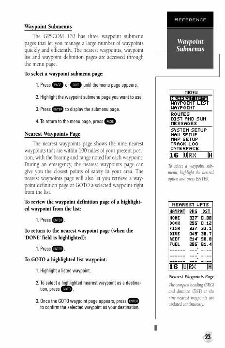
Nearest Waypoints Page
The nearest waypoints page shows the nine nearestwaypoints that are within 100 miles of your present posi-tion, with the bearing and range noted for each waypoint.During an emergency, the nearest waypoints page cangive you the closest points of safety in your area. Thenearest waypoints page will also let you retrieve a way-point definition page or GOTO a selected waypoint rightfrom the list.
To review the waypoint definition page of a highlight-ed waypoint from the list:
1. Press E.
To return to the nearest waypoint page (when the‘DONE’ field is highlighted):
1. Press E.
To GOTO a highlighted list waypoint:
1. Highlight a listed waypoint.
2. To select a highlighted nearest waypoint as a destina-tion, press G.
3. Once the GOTO waypoint page appears, press Eto confirm the selected waypoint as your destination.
WaypointSubmenus
Reference
23
To select a waypoint sub-menu, highlight the desiredoption and press ENTER.
Nearest Waypoints Page
The compass heading (BRG)and distance (DST) to thenine nearest waypoints areupdated continuously.
170 manual pages rev D 9/21/98 9:23 AM Page 23

Waypoint List Page
The waypoint list page provides you with a completelist of all waypoints currently stored in the unit. The totalnumber of used and empty waypoints is indicated abovethe waypoint list. From the waypoint list page, you canretrieve a waypoint definition page, delete all user-defined waypoints, or GOTO a selected waypoint.
If a waypoint is currently used in a route, the lowestroute number will be indicated to the left of the waypointname.
To review the waypoint definition page of a highlight-ed list waypoint:
1. Press E.
To return to the waypoint list page (with the ‘DONE’field highlighted):
1. Press E.
To GOTO a list waypoint:
1. Use the arrow keypad to scroll through the list andselect a waypoint.
2. To select a highlighted waypoint as a destination,press G.
3. Once the GOTO waypoint page appears, press Eto confirm the selected waypoint as your destination.
To delete all user-defined waypoints:
1. Use the arrow keypad to move the cursor highlight tothe ‘delete all waypoints’ field and press E.
A warning page will appear, asking if you are sure youwant to delete all user-defined waypoints and routes. Ifyou want to continue and delete:
1. Press the left arrow key to highlight the ‘Yes’ field.
2. Press E.
3. Press the left arrow key to return to the menu page.
If you do not want to delete all waypoints:
1. Press E with the ‘No?’ field highlighted.
Creating &Using
Waypoints
Reference
24
Waypoint List Page
The total number of usedand available waypoints isindicated at the top of thepage.
Deleting all user waypoints will also delete all routesstored in memory.
170 manual pages rev D 9/21/98 9:23 AM Page 24

Waypoint Definition Page
The last of the three waypoint submenu pages is thewaypoint definition page. This page lets you create newwaypoints manually, or review and edit existing way-points. To create a new waypoint manually, you’ll need toknow its position coordinates or its distance and bearingfrom an existing waypoint.
To create a waypoint by entering coordinates:
1. If a waypoint is currently displayed in the name field,highlight ‘NEW?’ and press E. Then press the leftarrow key to clear the name field.
2. If a waypoint is not displayed, move the cursor to thename field and enter the new waypoint’s name.
3. Use the arrow keypad to enter your waypoint nameand to move to the next character position.
4. Press E to confirm the waypoint name. The posi-tion field will now become highlighted, with the receiv-er’s last known position shown, if one exists.
5. Press E to begin entry of the position.
6. Use the arrow keypad to enter your position, and tomove to each character field.
7. Press E to confirm and save your coordinates.The default waypoint comment (UTC date and time ofcreation) will appear, and the highlight will move to‘DONE?’.
8. Press E to return to the menu page.
Creating &Using
Waypoints
Reference
25
PositionCoordinates
ReferenceWaypoint
WaypointName
Distance FromReferenceWaypoint
Bearing fromReferenceWaypoint
FunctionPrompts
Wpt Definition Page
Use the waypoint defini-tion page to review, renameor delete stored waypointsand to create new way-points manually.
After selecting entry of a‘NEW’ waypoint, an emptywaypoint screen will appear.Note: You must enter aname for the waypoint orthe highlight will notadvance to the next field.
WaypointComment Field
170 manual pages rev D 9/21/98 9:23 AM Page 25

Reference Waypoints
To create a new waypoint manually without knowingits position coordinates, you’ll need to enter its bearingand distance from an existing waypoint, or your presentposition. The GPSCOM 170 will then calculate the posi-tion coordinates for you.
To create a new waypoint by referencing a knownwaypoint:
1. Highlight the ‘NEW?’ field and press E.
2. Enter the name of your new waypoint.
3. Press E to confirm the waypoint name. The posi-tion field will now become highlighted, with the receiver’s last known position shown.
4. Move the cursor to the reference field.
5. Press E to begin entry of the reference waypoint.Leave the reference field blank to use your presentposition.
6. Use the arrow keypad to enter the waypoint name.
7. Press E to confirm your entry.
8. Enter the bearing and distance of your new waypointfrom the reference waypoint. Remember to use theE key to begin entry and confirm each field. Thecoordinates will be calculated and saved for your newwaypoint.
9. Press E (with the ‘done’ field highlighted) toreturn to the menu page.
Creating &Using
Waypoints
Reference
26
To re-define an existingwaypoint’s position coordi-nates from the waypointdefinition page, simplyhighlight the DST field andpress ENTER. Use theLEFT arrow key to set thedistance to 0.00, and pressENTER to confirm.
The old coordinates will bereplaced by the coordinatesof your present position(you must have a valid 2D– or 3D– position fix).
170 manual pages rev D 9/21/98 9:23 AM Page 26

Editing Existing Waypoints
The waypoint definition page also allows you tochange the name, coordinates, comment or referencewaypoint field for a stored waypoint.
To edit the name, coordinates, comment, or referencewaypoint field:
1. Highlight the field you want to edit. Press E tobegin entry in the selected field.
2. Enter your new data.
3. Press E to confirm your changes.
Waypoint Comments
Each waypoint stored in the GPSCOM 170 has auser-defined 16 character comment field. The defaultcomment is the UTC date and time of the waypoint’s creation.
To change or add a comment:
1. Highlight the comment field. Use the left arrow of thearrow keypad to clear the comment field.
2. Press E to begin entry of your comment.
3. Enter the comment and press E to confirm.
Renaming and Deleting Waypoints
The rename and delete function fields are located atthe bottom left of the waypoint definition page (you’llneed to use the arrow keypad to move the field highlightout of its standard up-and-down scrolling sequence).
Creating &Using
Waypoints
Reference
27
The waypoint commentfield will automaticallyassign the date and time ofcreation to the waypointcomments field. You mayenter a 16–character usercomment at any time.
To access the rename func-tion from the waypoint definition page, highlight the ‘RENAME?’ prompt andpress ENTER.
170 manual pages rev D 9/21/98 9:23 AM Page 27

To rename a stored waypoint:
1. Highlight the ‘RENAME?’ field and press E.
2. Enter the new waypoint name and press E.
3. Press E to confirm your changes.
To delete a stored waypoint (you can’t delete a routewaypoint without deleting it from a route):
1. Highlight the ‘DELETE?’ field, press E, andselect ‘YES’.
2. Press E to delete the waypoint.
Scanning Waypoints
As you manually enter a waypoint’s name, theGPSCOM 170’s waypoint scanning feature will automati-cally display the first numerical or alphabetical match ofthe character you have entered to that point. This helpseliminate the need to enter a waypoint’s complete name.
To scan waypoints from a waypoint field:
1. Highlight the waypoint name field and press E.
2. Press the left arrow key to clear the name field.
3. Use the keypad to scroll through waypoints.
4. If you have more than one waypoint that begins withthe same letter or number, you must use the rightarrow key to move to the next character positions asneeded. Only the first character match is listed foreach character set.
5. Once you’ve found the desired waypoint, press E.
Creating &Using
Waypoints
Reference
28
To delete a waypoint, con-firm the ‘Yes?’ prompt.Route or active waypointsmay not be deleted untilthey are removed from theroute or the GOTO hasbeen cancelled.
The waypoint scanning fea-ture will offer the first way-point that matches the char-acter or characters youhave entered to that point.
170 manual pages rev D 9/21/98 9:23 AM Page 28

VHF Communication Pages
To move back and forth between the GPS and VHFpages, press the C key. There are three com VHFpages in a continuous loop: channel definition, comsetup, and memory bank. Press C to exit the GPSpages and enter the com pages. Try scrolling through thecom pages by pressing P You can also scroll in theopposite direction or return to a previous page by pressing Q.
Press P repeatedly until you access the com setuppage.
Com Setup Page
The com setup page allows you to do the following:
• Change the mode of operation
• Customize the scanning setup
• Set the timeout feature (scanning delay)
• Select the band of operation
• Change the call channel
• Access the line of sight calculator page
Com Setup Page
VHF ComPages
Reference
29
Com Setup PageChannel Page Memory Bank Page
P
Q
170 manual pages rev D 9/21/98 9:23 AM Page 29

Three operating modes are available:
• Com On— (Default) Enables all VHF communica-tion features.
• Com Off— Disables all VHF communication fea-tures. Use this mode if you only want to use GPS orif battery life is a concern.
• Weather Alert— Accesses the weather alert audiopage. Muting the weather broadcast audio will causethe GPSCOM 170 to remain silent until the NationalWeather Service activates an alert tone.
To select an operating mode:
1. Highlight the ‘Com Mode’ field and pressE.
2. Use the arrow keypad to select an option, and pressE to confirm your choice.
Selecting the weather alert mode option accesses theweather alert page where you can choose to mute theweather broadcast audio. The receiver will unmute andremain unmuted once a severe weather tone is receivedfrom the NWS.
To mute the weather broadcast audio:
1. Highlight the ‘Com Mode’ field and pressE.
2. Use the arrow keypad to select ‘Weather Alert?’ andpress E. The weather alert mode submenu willappear with the audio field highlighted.
3. Press Eto select ‘Mute’.
4. PressC to exit the weather alert mode page.
Selecting a com mode on thecom setup page.
Weather Alert Page
30
VHF OperatingModes
Reference
170 manual pages rev D 9/21/98 9:23 AM Page 30

Scanning Setup
The com setup page also provides for scanning setup.The GPSCOM 170 scans, which means it automaticallylistens to a number of channels in rapid succession, hes-itates on an active channel until the conversation stops,and then moves on to the next channel.
The GPSCOM 170 can be programmed to scan allchannels for the band you have selected, or scan a bankof memory channels.
To select a scanning type:
1. On the com setup page, highlight ‘SCAN’ field andpress E.
2. Use the arrow keys to select the desired memory bankor ‘ALL CHANNELS’.
3. PressE to confirm the selection.
4. Press S to activate the scanning.
5. Press S or PTT to stop scanning.
Scanning Modes
The GPSCOM 170 has two scanning modes: normaland priority.
Normal scanning (the default setting) scans throughall channels/memory channels in sequence. Channel 16 ischecked in sequence as with the other channels.
Priority scanning scans through all channels/memorychannels in sequence while constantly monitoring chan-nel 16. When a signal is detected on channel 16, the unitpauses on channel 16 until the signal disappears. When asignal is detected on a channel other than 16, channel 16will be monitored every 2 seconds.
To select priority scan:
1. Highlight ‘COM MODE’ field and press E.
2. Use the arrow keypad to select ‘Priority’ and pressE.
3. Press E to confirm the selection.
Selecting ‘ALL CHANNEL’scanning.
The GPSCOM 170 in prior-ity scan mode.
Scanning Setup& Modes
Reference
31
170 manual pages rev D 9/21/98 9:23 AM Page 31

Scan Timeout
After each transmission has ended, you may want toenter a 2-3 second delay, allowing you to hear both sidesof a conversation. This delay is put on all channels.
To enter a delay time:
1. Highlight the ‘TIMEOUT’ field and press E.
2. Use the arrow keypad to select a desired delay time upto 99 seconds and press E.
Selecting an Operating Band
Selecting an operating band selects a pre-programmedgroup of channels which covers operation in U.S.,Canadian, or International waters. The default setting forband operation is USA.
To change the operating band:
1. Highlight the ‘BAND’ field and press E.
2. Use the arrow keypad to select USA, Canada, or INT’Land press E.
3. Press E to confirm the selection.
Calling Channel
The calling or hailing channel is the channel used toinitiate a call to another vessel, typically Channel 16 or 9.You can change the call channel on the com setup page.Note: When the call channel is changed, the new callchannel becomes the second channel in both dual and triwatch.
To change the call channel:
1. Highlight the ‘CALL CHANNEL’ field.
2. Use the UP or DOWN channel selection keys to selecta new channel and press E to confirm.
The GPSCOM 170 is initial-ly set for U.S. operation.
Changing the call channelon the com setup page.
Changing CallChannels
Reference
32
170 manual pages rev D 9/21/98 9:23 AM Page 32

VHF Line-of-Sight Calculator Page
The GPSCOM 170’s line-of-sight calculator page canbe used to estimate the transmitting and receiving dis-tance between the unit and another station.
Regardless of transmitter power, VHF marine radio’stransmitting and receiving range is generally limited by“line of sight.” This means that you must be located suchthat land masses, the curvature of the earth, or anythingelse that would limit your ability to see in a straight linedoes not substantially come between your antenna andthe antenna you are communicating with.
If you know the height of your vessel’s receivingantenna and the height of the transmitting antenna at thestation you desire to receive from, the probable range ofcommunications can be automatically calculated usingthe line-of-sight calculator page.
To access the line of sight calculator page from thecom setup page:
1. Highlight the ‘LINE OF SIGHT’ field and press E.
The top section of the line of sight calculator pagedisplays the transmitting antenna height field and receiv-ing antenna height field. The bottom of the page displaysthe line-of-sight calculation field.
To determine an approximate line of sight distance:
1. Highlight the ‘Transmitting Antenna Height’ field andpress E.
2. Using the arrow keypad, enter the known height ofyour antenna (the default value is 5 ft., which is theapproximate height from the deck to bottom of the flexantenna with the radio being held in your hand. Afteryou enter a height, press E.
3. Highlight the ‘Receiving Antenna Height’ field andpress E.
4. Enter the known height of the receiving antenna usingthe arrow keypad and press E.
5. The approximate line of sight distance (the probablerange of communication) will appear in the ‘LINE OFSIGHT’ field.
IMPORTANT!
Antenna height, more thanany other factor, is respon-sible for determining howfar you can transmit. Anantenna which is mountedup high can “see” fartherover the horizon.
Line-Of-SightCalculator
Page
Reference
33
Line-Of-SightCalculator Page
170 manual pages rev D 9/21/98 9:23 AM Page 33

Memory Bank Page
The memory bank page lets you store five groups ofchannels for custom scanning, complete with user com-ments. The memory channels are partitioned into“banks”, specifically 5 banks of 10 channels each. Thememory banks are numbered 1-5 and displayed at thetop of the page. From the memory bank page you’ll beable to perform the following functions:
• Select a numbered bank
• Enter user comments
• Enter channels into memory
• Copy a bank’s contents to another bank
• Clear (delete) a bank
From the com page group, press P repeatedlyuntil the memory bank page appears.
To select a numbered bank:
1. Highlight the ‘MEMORY BANK’ field and press E.
2. Use the arrow keypad to select the desired bank.
To enter user comments:
1. Highlight the comment field and pressE. The firstcharacter position of the comment field is highlighted.Press the left arrow key on the arrow keypad to clearthe field.
2. Enter a character using the arrow keypad. Once thedesired character is selected, move to the next charac-ter position using the right arrow on the arrow keypad.You can enter up to 16 characters.
3. PressE to confirm the entry.
If an error is made during entry, use the right or leftarrow keys on the arrow keypad to move to the positioncontaining the incorrect character. Enter the correct char-acter and press E when you are finished.
Entering memory bank usercomments.
Memory BankPage
Reference
34
Memory Bank Page
170 manual pages rev D 9/21/98 9:23 AM Page 34

To enter channels:
1. Highlight the first blank ‘CHANNEL’ field and pressE.
2. Enter a channel of your choice using the arrow keypad andpress E. The appropriate band for the channel youhave selected will be displayed next to the channel number.Note: You cannot enter weather channels into memory, norcan you enter channels of different bands in the same bank.
Copying and Clearing
The bottom of the memory bank page displays the‘COPY TO’ and ‘CLEAR’ fields which allow you to copy alist to another bank or clear a list completely.
To copy a list to another bank:
1. Highlight the ‘COPY TO’ field and press E.
2. Enter the bank number that you want the currently dis-played list copied to and press E.
Individual or groups of channels within a bank cannot becopied.
To remove (delete) all channels from a memory bank:
1. Highlight the ‘CLEAR’ field and press E. A warningpage will appear asking you if you are sure you want toremove all the channels from the bank.
2. Select ‘YES?’ and press E.
Memory List Editing
Once a list has been entered into a bank, it can be edit-ed at any time.
To edit a list:
1. Use the arrow keypad to select the channel you want toedit and press E.
An on-screen menu of editing choices will appear, withoptions for selecting, inserting, removing or changing thehighlighted channel. Use the arrow keys to select amongthe editing choices and press E.
‘CLEAR BANK’ warningpage.
You cannot enter weatherchannels into memory, norcan you enter channels ofdifferent bands in the samebank.
Memory BankPage
Reference
35
170 manual pages rev D 9/21/98 9:23 AM Page 35

• SELECT— To select the active channel and displaythe channel usage page, highlight the ‘SELECT’prompt and press E.
• INSERT— To insert a new channel, highlight the‘INSERT?’ prompt and pressE.
• REMOVE— To remove the selected channel, high-light the ‘REMOVE’ prompt and press E.
• CHANGE— To replace the selected channel with anew channel, highlight the ‘CHANGE’ prompt andpress E.
Channel Definition Page
The GPSCOM 170’s channel definition page reviewslockout and usage information for the active channel.
The top section of the page displays the current(active) channel number, mode of operation (simplex orduplex), band of operation (USA, Canada, orInternational)–(or ‘WX’ for a weather channel), and the‘LOCKOUT’ field.
Channel Definitions
There is a maximum of three definition fields for eachchannel, with the FCC’s default channel usage displayed.If the designated usage for a channel should ever changedue to a change in regulations, you can change the defi-nition accordingly.
To change a channel definition:
1. Highlight the definition field you want to change andpress E.
2. Use the arrow keypad to scroll through the list of avail-able definitions and press E to confirm the selec-tion.
Just below the channel definition list is the‘DEFAULT?’ prompt which allows you to return the chan-nel definitions back to their original (default) settings.
Changing a default defini-tion setting.
Channel DefinitionPage
ChannelDefinition Page
Reference
36
170 manual pages rev D 9/21/98 9:23 AM Page 36

To return the definitions back to their default set-tings:
1. Highlight ‘DEFAULT?’ and press E.
The ‘DONE?’ prompt located below the ‘DEFAULT?’prompt confirms any changes that were made and returnsyou to the previously viewed page.
To confirm changes made on the channel definitionpage and return to the previously viewed page:
1. Highlight ‘DONE?’ and press E.
Channel Lockout
Channel lockout allows you to bypass a channel dur-ing scanning.
To lock a channel out:
1. Highlight ‘LOCKOUT’ and press E.
2. Use the arrow keys to select ‘YES’.
3. Press E to confirm.
4. To unlock a channel, repeat the steps above (exceptselect ‘NO’ in step 2).
ChannelLockout
Reference
37
Adding a channel to memory bank 2 from thememory page.
Memory Page
170 manual pages rev D 9/21/98 9:23 AM Page 37

Memory Page
The memory page (see sidebar, page 37) allows youto easily add the active channel to a memory bank. It alsodisplays channel number, type (duplex/simplex), band(US, Canada, International), and channel usage.
To select the memory page:
1. Press M.
To add a channel to memory from the memory page:
1. Highlight ‘Add to the ‘Memory Bank’ field and pressE. Select the desired bank number using thearrow keypad.
2. Highlight ‘SAVE?’ and press E. The channel isnow saved to the bank you selected.
Tri Watch
In addition to dual watch scanning (see the gettingstarted section) a tri watch mode is available. Tri watchscans between channel 16, 9 (or whatever the call chan-nel is set to) and the last selected channel. This feature ishandy when you need to monitor channel 16 for emer-gency communication, but also want to listen to channel9 for hailing calls, and a third channel for another pur-pose.
To activate tri watch:
1. Press T twice. The unit will scan between chan-nel 16 , 9 and the last selected channel, stopping whentraffic is detected. Press T or PTT to cancel triwatch.
Power Override
On certain channels, the FCC requires the transmit-ting power to be limited to, and remain at one watt (seeAppendix C). The default setting on these channels is onewatt and cannot be changed. There are also some onewatt ‘initial’ channels, in which the FCC allows the powerto be increased to five watts under certain cicumstances.
To switch to five watts:
1. Press the transmit power button which is locatedbelow the PTT button.
When the unit is in triwatch mode, ‘TRI’ is dis-played in the VHF statusbar.
MemoryPage/Tri Watch
Reference
38
IMPORTANT!
The GPSCOM 170 givesyou the option of transmit-ting using 1 watt or 5 wattsof power. Transmitting at 1watt of power is useful for short-range conversa-tions and won’t interferewith a large number ofboaters. Transmitting at 1watt also prolongs batterylife. The VHF status barwill display an ‘L’ when 1watt is being used or an ‘H’when 5 watts is selected.
170 manual pages rev D 9/21/98 9:23 AM Page 38

Selecting a GOTO Destination
The GPSCOM 170 provides four ways to navigate toa destination: GOTO, MOB, TracBack and route naviga-tion. The most basic method of selecting a destination isthe GOTO function, which lets you choose any storedwaypoint as the destination and quickly set a directcourse from your present position.
To activate the GOTO function:
1. Press G. The GOTO waypoint list, an alphabeticallist of all available waypoints, will appear.
2. Select the waypoint you want to navigate to (it mayalready be highlighted).
3. Press E to confirm, or Q to stop selection ofa GOTO destination and return to the previous page.
Once a GOTO waypoint has been activated, theGPSCOM 170 will provide steering guidance to the des-tination until either the GOTO is cancelled or the unithas resumed navigating the active route (see page 46).
To cancel an active GOTO:
1. Press G.
2. Use the arrow keypad to move the field highlight to the‘CANCEL GOTO?’ prompt at the bottom of the page andpress E.
Man Overboard Function
The GPSCOM 170’s man overboard function (MOB)lets you simultaneously mark and set a course to a posi-tion for quick response to passing positions (like the spotwhere your hat blew overboard).
To activate the MOB mode:
1. Press G twice. The GOTO waypoint page willappear with ‘MOB’ selected as the default destination.
2. Press E to begin MOB navigation.
The GPSCOM 170 will now guide you to the MOBwaypoint until the MOB GOTO is cancelled (see “cancelGOTO” above). If you want to save the MOB waypoint,be sure to rename it, because it will be overwritten thenext time a MOB is executed.
GOTO & MOBNavigation
Reference
39
Select a destination way-point from the GOTOwaypoint list.
Once the MOB mode hasbeen activated, steeringguidance will be provided bythe compass or highwaypage. Activating anotherMOB will overwrite the pre-vious MOB waypoint.
170 manual pages rev D 9/21/98 9:23 AM Page 39

TracBack Navigation
The third method of navigating to a destination is byusing the GPSCOM 170’s TracBack feature. The TracBackfunction allows you to quickly and easily retrace yourpath using the track log automatically stored in thereceiver’s memory. The advantage of the TracBack featureis to eliminate the need to mark waypoints along the wayand manually create and activate a route back to whereyou began your trip.
The TracBack route is created by reducing your cur-rent track log into a route of up to 30 waypoints, and acti-vating an inverted route along those points. Once activat-ed, a TracBack route will lead you back to the oldest tracklog point stored in memory, so it’s usually a good idea toclear the existing track log at the starting point of yourcurrent trip (e.g. the dock) before you get started.
To clear the track log and define a starting point for aTracBack route:
1. From the map page, press E. Highlight the ‘TRACK SETUP?’ option and press E. The track logpage will appear.
2. Use the arrow keypad to highlight ’CLEAR LOG’ andpress E.The clear log confirmation page willappear. Highlight ‘YES’ and press E.
To activate a TracBack route:
1. From the map page, press E and highlight the‘TRACK LOG’ option.
2. Press E to access the track log page.
3. Highlight the ‘TRACBACK?’ option and press E.
Once the TracBack function has been activated, theunit will take the track log currently stored in memoryand divide it into segments called legs. Up to 30 tempo-rary waypoints (e.g., ‘T001’) will be created to mark themost significant features of the track log in order to dupli-cate your exact path as closely as possible. A TracBackroute from your present position to the oldest track logpoint will be created as the active route (the active routepage will appear), and provide steering guidance to eachwaypoint back to the starting point of your track log.
TracBackNavigation
Reference
40
Clearing the log before youget started will define theposition the TracBack func-tion will return you to.
Highlight the ‘TRACBACK’prompt and press ENTER tobegin TracBack navigation.An on-screen status box willmonitor the progress of theTracBack calculation.
170 manual pages rev D 9/21/98 9:23 AM Page 40

Tips on Using TracBack
To get the most out of the TracBack feature, remem-ber the following tips:
• Always clear your track log at the exact point thatyou want to go back to (trail head, truck, dock,etc.). The ‘RECORD’ option on the track log setuppage must be set to the ‘Yes’ position.
• There must be at least two track log points stored inmemory to create a TracBack route.
• If there are not enough available waypoints inmemory to create a TracBack route, you will bealerted with a ‘waypoint memory full’ message, andthe receiver will use any available waypoints to cre-ate a TracBack route with an emphasis on the tracklog closest to the destination (the oldest track logpoint in memory).
• If the ‘CRITERIA’ option on the track log setup pageis set to a time interval, the TracBack route may notfollow your exact path (keeping the criteria set toautomatic will always provide the best TracBackroute).
• If the receiver is turned off or you lose satellite cov-erage during your trip, the TracBack route will sim-ply draw a straight line between any point wherecoverage was lost and where it resumed.
• If the changes of direction and distance of yourtrack log are very complex, 30 waypoints may notbe enough to accurately mark your exact path. Thereceiver will then assign the 30 waypoints to themost significant points of your track, and simplifysegments with fewer changes in direction.
• If you want to save a TracBack route, copy route 0to an open storage route before activating anotherTracBack. Activating another TracBack or storageroute will overwrite the existing TracBack route.
• Whenever a TracBack route is activated, the receiv-er will automatically erase any temporary way-points (e.g., ‘T001’) that are not contained in routes1-19. If there are temporary waypoints stored inroutes 1-19, the receiver will create any new tem-porary waypoints using the first three-digit numberavailable.
TracBackNavigation
Reference
41
The TracBack feature willnavigate your track logback to the oldest point inthe receiver’s memory.
The track log will be dividedinto segments with tempo-rary waypoints to create a route back to the begin-ning of the track log.
170 manual pages rev D 9/21/98 9:23 AM Page 41

Creating and Using Navigation Routes
The last form of navigating to a destination with theGPSCOM 170 is by creating a user-defined route. Theroute navigation feature lets you plan and navigate acourse from one place to another using a set of pre-defined waypoints. Routes are often used when it’s notpractical, safe or possible to navigate a direct course to aparticular destination (e.g., through a body of water orimpassable terrain).
Routes are broken down and navigated in smallersegments called ‘legs’. The waypoint you are going to in aleg is called the ‘active to’ waypoint, and the waypointimmediately behind you is called the ‘active from’ way-point. The line between the ‘active to’ and the ‘activefrom’ waypoint is called the ‘active leg’.
Whenever you activate a route with the GPSCOM170, it will automatically select the route leg closest toyour position as the active leg. As you pass each waypointin the route, the receiver will automatically sequence andselect the next waypoint as the ‘active to’ waypoint.
RouteNavigation
Reference
42
Waypoint 2(‘active to’ waypoint)
Waypoint 1(‘active from’ waypoint)
‘Active Leg’
ä
ä ä©}
170 manual pages rev D 9/21/98 9:23 AM Page 42

Routes Definition Page
The GPSCOM 170 lets you create and store up to 20routes of 30 waypoints each. Routes are created, copiedand edited through the route definition page, which isaccessed through the menu page.
To select the route definition page:
1. Press P until the menu page appears.
2. Highlight the ‘ROUTES’ option.
3. Press E to display the route definition page.
4. To return to the menu page, press P.
The route number field is displayed at the top of thepage, with a 16-character user comment below. If no usercomment is entered, the field will display the first and lastwaypoint in the route. The waypoint list in the middle ofthe page accepts up to 30 waypoints for each route, withfields for desired track and distance between legs. Thetotal distance of the route is indicated below the waypoint list.
The bottom of the route definition page features sev-eral function fields which let you copy, clear, invert oractivate the displayed route. Routes 1-19 are used as stor-age routes, with route 0 always serving as the active routeyou are navigating. If you want to save a route currentlyin route 0, be sure to copy it to another open route, as itwill be overwritten by the next route activation.
RouteNavigation
Reference
43
If you’re heading out with-out a planned route, themark function can be usedto quickly create a routeback to your starting point.
Create a series of waypointsalong the way with themark key and save them toan open route from themark position page. Whenyou’re ready to head back,simply activate the routeyou created in invertedorder.
CommentField
DesiredTrack of Leg
Total Distance
Route Number
Copy Field
Function Prompts
Leg Distance
170 manual pages rev D 9/21/98 9:23 AM Page 43
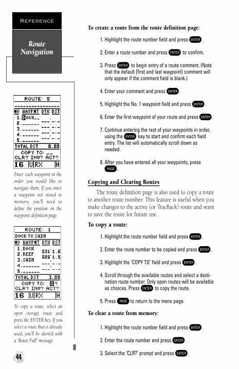
To create a route from the route definition page:
1. Highlight the route number field and press E.
2. Enter a route number and press E to confirm.
3. Press E to begin entry of a route comment. (Notethat the default [first and last waypoint] comment willonly appear if the comment field is blank.)
4. Enter your comment and press E.
5. Highlight the No. 1 waypoint field and press E.
6. Enter the first waypoint of your route and press E.
7. Continue entering the rest of your waypoints in order,using theE key to start and confirm each fieldentry. The list will automatically scroll down as needed.
8. After you have entered all your waypoints, pressP.
Copying and Clearing Routes
The route definition page is also used to copy a routeto another route number. This feature is useful when youmake changes to the active (or TracBack) route and wantto save the route for future use.
To copy a route:
1. Highlight the route number field and press E.
2. Enter the route number to be copied and press E.
3. Highlight the ‘COPY TO’ field and press E.
4. Scroll through the available routes and select a desti-nation route number. Only open routes will be availableas choices. Press E to copy the route.
5. Press P to return to the menu page.
To clear a route from memory:
1. Highlight the route number field and press E.
2. Enter the route number and press E .
3. Select the ‘CLR?’ prompt and press E.
RouteNavigation
Reference
44
Enter each waypoint in theorder you would like tonavigate them. If you entera waypoint not stored inmemory, you’ll need todefine the position on thewaypoint definition page.
To copy a route, select anopen storage route andpress the ENTER key. If youselect a route that is alreadyused, you’ll be alerted witha ‘Route Full’ message.
170 manual pages rev D 9/21/98 9:23 AM Page 44

Clearing Routes (con’t.)
The clear route warning will appear, asking you toconfirm that you want to remove all waypoints from theroute.
1. Highlight the ‘Yes?’ field.
2. Press E to confirm your action.
3. Press P to return to the menu page.
Activating And Inverting Routes
After a route has been entered, it can be activated in itsdefined sequence or inverted from the route definitionpage. The process of activating or inverting a stored routetakes a storage route (routes 1-19) and copies it into theactive route (route 0) for navigation. The storage route isnow no longer needed and will be retained in its originalformat under its existing route number.
This system allows you to have an active route that youmay edit during navigation and save as an entirely newroute from the original. You will have to copy the activeroute to an unused storage route to save it, since new routeor TracBack activation overwrites route 0.
To activate a route:
1. Select the route definition page and press E to acti-vate the route number field.
2. Enter the route number to be activated and press E.
3. Move the field highlight to the ‘ACT?’ prompt and pressE.
Inverting a route allows you to navigate route legs ininverted order without editing the original route.
To activate a route in inverted order:
1. Follow the steps above, but select the ‘INV?’ prompt andpress E.
RouteNavigation
Reference
45
Clearing a route onlyremoves the waypoints fromthe route selected. The way-points used will remain inthe receiver’s memory.
To activate a route, high-light the ‘ACT?’ prompt andpress ENTER.
170 manual pages rev D 9/21/98 9:23 AM Page 45

Active Route Page
Once a route has been activated, the active route pagewill appear, displaying the waypoint sequence of yourroute with the estimated time enroute (ETE) at your pre-sent speed and distance to each waypoint. As long as youare navigating an active route, the active route page willbecome part of the main page sequence of the unit.
The active route page will also allow you to changethe ETE field to display desired track (DTK) or estimatedtime of arrival (ETA) for each leg. In addition, you canalso clear or invert the active route.
To display DTK or ETA for each leg:
1. Highlight the estimated time enroute (ETE) field andpress E.
2. Use the up or down arrow keys to select ‘DTK’ or ‘ETA’and press E.
The active route page also allows you to clear (stopnavigating) or invert the active route without using theroute definition page.
To invert a route from the active route page:
1. Move the field highlight to the ‘INVERT?’ prompt.
2. Press E to invert the route.
To clear the active route from the active route pageand stop route navigation:
1. Select the ‘CLEAR?’ prompt.
2. Press E to clear the active route.
Editing Routes
Once a route has been created and stored, it can beedited at any time, even if it is the active route.
To edit a route from the active route page or the routedefinition page:
1. Select the waypoint you want to edit and press E.
RouteNavigation
Reference
46
Active Route Page
Whenever you have anactive route, the active routepage will appear in themain page sequence afterthe compass/highway page.
To edit or review a routewaypoint from the activeroute page, highlight thedesired waypoint and pressENTER.
170 manual pages rev D 9/21/98 9:23 AM Page 46

Editing Routes (con’t.)
An on-screen menu of editing choices will appear,with options for reviewing, inserting, deleting or chang-ing the waypoint field highlighted. Use the up and downarrow keys to select among the editing choices.
Once you’ve selected a waypoint from the route list,choose a menu function:
1. To review the definition page for the waypoint, high-light the ‘REVIEW?’ prompt and press E.
2. To add a new waypoint that precedes the selectedwaypoint, highlight the ‘INSERT?’ prompt and pressE.
3. To remove the selected waypoint, highlight the‘REMOVE?’ prompt and press E.
4. To replace the selected waypoint with a new waypoint,highlight the ‘CHANGE?’ prompt and press E.
Use the route waypoint editing instructions describedearlier for creating a route to complete your changes. Ifyou are editing the active route (route 0), copy your newroute version to an empty route to save it, because theactive route will be overwritten by a new route activation.
If you add, delete or change the first or last waypointof a route, the default comment (first and last waypoint)will automatically be updated after your changes.
On-Route GOTOs
At the beginning of this section, we mentioned thatthe GPSCOM 170 will automatically select the route legclosest to your position as the active leg. This will giveyou steering guidance to the desired track of the activeleg. If you would prefer to steer directly to a route way-point, you can perform an ‘on-route GOTO’ from theactive route page.
1. Highlight the desired route waypoint and press G.
2. Once the GOTO waypoint page appears, press Eto confirm the on-route GOTO waypoint.
Note that after you reach the on-route GOTO way-point, the GPSCOM 170 will automatically resume navi-gating the rest of the route in sequence.
RouteNavigation
Reference
47
Use the on-screen menu toselect the desired editingfunction.
You can skip ahead to anyroute waypoint by highlight-ing the desired waypointand pressing the GOTO key.
170 manual pages rev D 9/21/98 9:23 AM Page 47

Selecting a User-Defined Navigation Page
Once you’ve selected a GOTO destination or activat-ed a MOB or route, the GPSCOM 170 will provide graph-ic steering guidance to the destination with one of twonavigation pages:
•The highway page (the default navigation page) pro-vides a graphic highway that shows your movementrelative to the desired course, with an emphasis onyour crosstrack error,(the distance and direction youare off course.) The highway page is well suited forboating and other activities with higher speeds andstraight–line courses to a destination.
•The compass page provides a directional pointer tothe destination, with a rotating compass graphic todisplay your direction of travel. The compass page isideal for activities like trawling or entering a harbor,and provides better steering guidance for slow-speed (e.g., walking) travel with many directional changes.
Both pages provide a digital display of the bearingand distance to the destination, your current speed andtrack over the ground, and course deviation indicator(CDI). You can select the desired navigation page at any time.
To select the compass or highway page:
1. Press P until the current navigation page appearsand press E. An on-screen box will appear, withthe navigation page not currently in use highlighted asthe default.
2. Press E to switch the navigation screen.
NavigationGuidance
Pages
Reference
48
To switch the navigationpage to the compass page,press ENTER twice.
To switch the navigationpage to the highway presen-tation, press ENTER twice.
Compass PageHighway Page
170 manual pages rev D 9/21/98 9:23 AM Page 48

Using the Highway Page
The highway page also provides graphic steeringguidance to a destination, with a greater emphasis on thestraight-line desired course and the distance and direc-tion you are off course. The bearing and distance to awaypoint, along with your current track and speed aredisplayed at the top of the screen, with your estimatedtime enroute (ETE) and velocity made good (VMG, or therate you are closing in on your destination) at the bottom.
As you head toward your destination, the middle sec-tion of the screen provides visual guidance to your way-point on a moving graphic ‘highway’. The moving arrowjust below the course deviation scale always points toyour selected waypoint relative to the direction you are moving.
Your present position is represented by the square inthe center of the course deviation scale. The line downthe middle of the highway represents your desired track.As you navigate toward a waypoint, the highway willactually move, indicating the direction you’re off course,relative to the position diamond on the CDI scale. To stayon course, simply steer toward the center of the highway.
If you do get off the desired course by more than1/5th of the selected CDI range, the exact distance youare off course will be displayed where the CDI scale set-ting normally appears. If you get too far off course (thehighway has disappeared), a message box will appear toindicate what course to steer to get back on course.
Highway Page
Reference
49
In this example, the high-way page indicates that youare off course to the left.Steer right to get back oncourse. Notice the emphasisof the highway page is onthe desired course.
If you get too far off course,a message box will appearto indicate what course tosteer to get back on coursemost efficiently.
Bearing toWaypoint
GraphicHighway
CDI Scale
Distance toWaypoint
Estimated Time Enroute
Velocity Made Good
Speed OverGround
Track OverGround
DestinationWaypoint
Pointer to Waypoint
170 manual pages rev D 9/21/98 9:23 AM Page 49
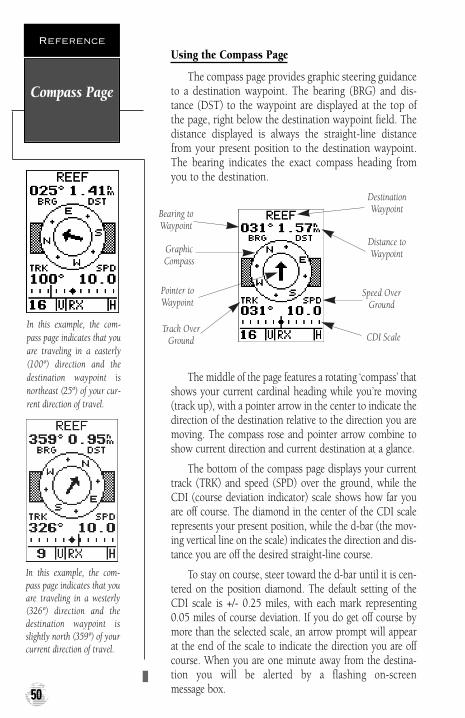
Using the Compass Page
The compass page provides graphic steering guidanceto a destination waypoint. The bearing (BRG) and dis-tance (DST) to the waypoint are displayed at the top ofthe page, right below the destination waypoint field. Thedistance displayed is always the straight-line distancefrom your present position to the destination waypoint.The bearing indicates the exact compass heading fromyou to the destination.
The middle of the page features a rotating ‘compass’ thatshows your current cardinal heading while you’re moving(track up), with a pointer arrow in the center to indicate thedirection of the destination relative to the direction you aremoving. The compass rose and pointer arrow combine toshow current direction and current destination at a glance.
The bottom of the compass page displays your currenttrack (TRK) and speed (SPD) over the ground, while theCDI (course deviation indicator) scale shows how far youare off course. The diamond in the center of the CDI scalerepresents your present position, while the d-bar (the mov-ing vertical line on the scale) indicates the direction and dis-tance you are off the desired straight-line course.
To stay on course, steer toward the d-bar until it is cen-tered on the position diamond. The default setting of theCDI scale is +/- 0.25 miles, with each mark representing0.05 miles of course deviation. If you do get off course bymore than the selected scale, an arrow prompt will appearat the end of the scale to indicate the direction you are offcourse. When you are one minute away from the destina-tion you will be alerted by a flashing on-screen message box.
Compass Page
Reference
50
In this example, the com-pass page indicates that youare traveling in a easterly(100º) direction and thedestination waypoint isnortheast (25º) of your cur-rent direction of travel.
In this example, the com-pass page indicates that youare traveling in a westerly(326º) direction and thedestination waypoint isslightly north (359º) of yourcurrent direction of travel.
Bearing toWaypoint
Pointer toWaypoint
Speed OverGround
DestinationWaypoint
Track OverGround CDI Scale
Distance toWaypointGraphic
Compass
170 manual pages rev D 9/21/98 9:23 AM Page 50

Moving Map Page
The GPSCOM 170 features a powerful real-time mov-ing map that can do much more than just plot yourcourse and route. The map page also provides you with atarget cursor that will let you pan ahead to nearby way-points, determine the distance and bearing to any mapposition, and mark new waypoints while you navigate.
The GPSCOM 170 also features dedicated zoom keysfor instant zooming. The map portion of the page dis-plays your present position as a diamond icon, with yourtrack and/or route displayed as small points. Nearby way-points are represented as squares, with the waypointname listed. You may select which features are shownthrough the map setup submenu page (see pages 54).
The four corners of the map page are used to displayvarious navigation data, including the bearing and dis-tance to a destination waypoint and your current trackand speed over the ground. The two fields at the top cor-ners of the map show your bearing and distance to one ofthree selectable destinations: an active destination way-point; a highlighted on-screen waypoint; or the panningtarget crosshair. If you are not navigating to a waypoint orusing the panning function, the top data fields will not bedisplayed. Your current track and speed are shown at thebottom corners of the display.
Moving MapPage
Reference
51
Range Rings
The GPSCOM 170 has on-screen range rings to helpyou estimate distances rela-tive to your present posi-tion. The value of each ringis determined by the currentzoom scale, and is equal to1/5 of the selected scale.
To turn the range rings dis-play on or off (the defaultsetting is off), see the mapsetup section instructionson page 54.
Bearing toWaypoint
Track OverGround
Speed Over Ground
Distance toWaypoint
PresentPosition
170 manual pages rev D 9/21/98 9:23 AM Page 51
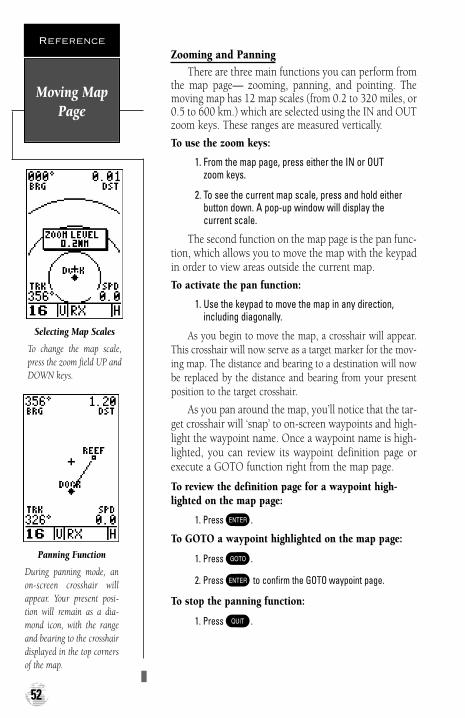
Zooming and PanningThere are three main functions you can perform from
the map page— zooming, panning, and pointing. Themoving map has 12 map scales (from 0.2 to 320 miles, or0.5 to 600 km.) which are selected using the IN and OUTzoom keys. These ranges are measured vertically.
To use the zoom keys:
1. From the map page, press either the IN or OUT zoom keys.
2. To see the current map scale, press and hold eitherbutton down. A pop-up window will display the current scale.
The second function on the map page is the pan func-tion, which allows you to move the map with the keypadin order to view areas outside the current map.
To activate the pan function:
1. Use the keypad to move the map in any direction,including diagonally.
As you begin to move the map, a crosshair will appear.This crosshair will now serve as a target marker for the mov-ing map. The distance and bearing to a destination will nowbe replaced by the distance and bearing from your presentposition to the target crosshair.
As you pan around the map, you’ll notice that the tar-get crosshair will ‘snap’ to on-screen waypoints and high-light the waypoint name. Once a waypoint name is high-lighted, you can review its waypoint definition page orexecute a GOTO function right from the map page.
To review the definition page for a waypoint high-lighted on the map page:
1. Press E.
To GOTO a waypoint highlighted on the map page:
1. Press G.
2. Press E to confirm the GOTO waypoint page.
To stop the panning function:
1. Press Q.
Moving MapPage
Reference
52
Selecting Map Scales
To change the map scale,press the zoom field UP andDOWN keys.
Panning Function
During panning mode, anon-screen crosshair willappear. Your present posi-tion will remain as a dia-mond icon, with the rangeand bearing to the crosshairdisplayed in the top cornersof the map.
170 manual pages rev D 9/21/98 9:23 AM Page 52

Using the Cursor to Mark and GOTO Waypoints
During panning, the crosshair represents a targetposition right on the moving map, with the range andbearing to the target displayed at the top corners of thescreen. You can also use the target crosshair to mark anew waypoint position or as a GOTO destination rightfrom the map field.
To mark the target crosshair position as a new waypoint:
1. Press M to capture the position.
2. Enter a new name and route number if you wish.
3. Press E to save the waypoint and return to themap page.
You can also use the target crosshair as an instantGOTO destination. Similar to the MOB mode, this func-tion will mark and instantly set a course for a new way-point called ‘MAP’.
To GOTO the target crosshair:
1. Press G to capture the position.
2. Press E to confirm the MAP GOTO.
If you want to save the MAP waypoint, be sure torename it, as it will be overwritten the next time a mapGOTO is executed.
Moving MapPage
Reference
53
Marking a Waypoint
To mark a new waypointwith the crosshair, simplypan to the desired positionand press the MARK key.
MAP GOTO
The crosshair may also beused to define a GOTO des-tination by panning to thedesired position and press-ing the GOTO key. If youwant to save the MAP way-point, be sure to rename it.
170 manual pages rev D 9/21/98 9:23 AM Page 53

Accessing the Map Setup and Track Setup Windows
You can access two additional pages—the map setuppage and the track setup page—by pressingE. whileon the map page. The map setup and track setup windowwill appear, ready for you to select one.
To select map setup or track setup:
1. Highlight either field, and press E.
Map Setup Page and Orientation
The map setup page lets you select map orientationand specify what items are displayed. The map may beoriented to ‘North Up,’ ‘Track Up’ (the direction of cur-rent travel), or ‘DTK Up’ (desired track up, or the direc-tion of travel to stay on course). The default setting istrack up.
To change the map orientation:
1. Highlight the ‘ORIENTATION’ field, and press E.Select the desired orientation, and pressE.
The rest of the map setup page lets you specify whatitems are displayed or plotted on the map page by selecting‘YES’ or ‘NO’ in the appropriate field.
• ’RINGS’—displays the three present position rangerings on the map.
• ’ROUTE’—plots the straight–leg lines between way-points of an active route and displays all route waypointnames.
• ’NEAREST’—shows the nine nearest waypoints to yourpresent position (not to the target cursor) on the map.
• ’NAMES’—displays the waypoint name for the ninenearest waypoints.
• ’TRACK LOG’—displays the number of track points up toa maximum of 950.
To turn a map item on or off:
1. Highlight ‘YES’ or ‘NO’ for the specific map item, and press E.
Track Log Setup Page
The track setup page lets you manage the track logdata. From this page, you can select whether to record atrack log and define how it is recorded.To turn the track log on or off:
1. Highlight the ‘RECORD’ field, and press E. Select‘YES’ or ‘NO’, and press E.
Map SetupPage
Reference
54
Accessing the map setuppage from the moving mappage.
Selecting ‘Track Up’ maporientation.
170 manual pages rev D 9/21/98 9:23 AM Page 54
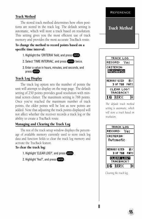
Track Method
The stored track method determines how often posi-tions are stored in the track log. The default setting isautomatic, which will store a track based on resolution.This setting gives you the most efficient use of trackmemory and provides the most accurate TracBack route.
To change the method to record points based on aspecific time interval:
1. Highlight the ‘CRITERIA’ field, and press E.
2. Select ‘TIME INTERVAL’, and press E twice.
3. Enter a value in hours, minutes, and seconds, andpress E.
Track Log Display
The track log option sets the number of points theunit will attempt to display on the map page. The defaultsetting of 250 points provides good resolution with min-imal screen clutter. The maximum setting is 768 points.Once you’ve reached the maximum number of trackpoints, the older points will be lost as new points areadded. Note that adjusting the track points displayed willnot affect whether the receiver records a track log or theability to create a TracBack route.
Managing and Clearing the Track Log
The rest of the track setup window displays the percent-age of available memory currently used to store track logdata and function fields to clear the track log memory andactivate the TracBack feature.To clear the track log:
1. Highlight ‘CLEAR LOG?’, and press E.
2. Highlight ‘Yes?’, and press E.
Track Method
Reference
55
The default track methodsetting is automatic, whichwill store a track based onresolution.
Clearing the track log.
170 manual pages rev D 9/21/98 9:23 AM Page 55

Menu Page
The GPSCOM 170 menu page provides access to sub-menu pages that are used to select and customize opera-tion and navigation setup. The 11 submenus are dividedinto categories by function. The waypoint and route man-agement submenus are discussed in their own respectivesections. We’ll now address the rest of the submenus inthe order they appear on the menu page.
To select a submenu page from the menu page:
1. Highlight the submenu page you want to view andpress E to display the submenu page.
2. To return to the menu page, press Q.
Distance and Sun Calculations
The distance and sun calculation page will give youthe distance and bearing between any two waypoints andwill calculate the sunrise and sunset (in local time) at adestination waypoint for a particular date.
To perform a distance and sun calculation:
1. Highlight the ‘from’ field and enter the desired way-point. Press E to move to the next field.
2. Highlight the ‘to’ field and enter the destination way-point. Press E to calculate the range and bearingto the destination waypoint.
3. Highlight the ‘date’ field and enter the date for yourdestination. Press E to display the sun information.
Message Page
The message page displays all current messages in theGPSCOM 170. There are two types of messages: tempo-rary alerts (eg., approaching a waypoint) and conditionalerts (eg., battery power is low). All messages are initial-ly indicated by a flashing on-screen box. After a tempo-rary alert has been viewed, it is cleared. Condition alertsare displayed on the message page until the condition isresolved. See Appendix E for a complete list of messages.
To view the message page:
1. Highlight the ‘MESSAGES’ field and press E.
Menu Page
Reference
56
Menu Page
To select a submenu, use theUP and DOWN keys tohighlight a menu option andpress ENTER.
Dis/Sun Calculation
The unit will calculate thesunrise and sunset times ofany stored waypoint or yourpresent position. To calcu-late, enter the date and yearand press ENTER.
170 manual pages rev D 9/21/98 9:23 AM Page 56

System Setup
The first setup page is the system setup page, whichis used to select the operating mode, time offset andscreen preferences. The GPSCOM 170 has three operat-ing modes:
• GPS Off? disables all of the unit’s GPS functionswhich will conserve battery power.
• GPS On enables all of the unit’s GPS functions,making it a fully operational unit.
• Simulator? allows you to operate the unit withoutacquiring satellites, and is ideal for practicing orentering waypoints and routes while at home.
To select an operating mode:
1. Highlight the ‘MODE’ field and press E.
2. Use the arrow keypad to select a mode and pressE.
Date and Time Setup
The date and time field is located directly below themode field. Because the time shown is UTC time, you willneed to enter a time offset to display the correct local timefor your area. To determine the time offset for your area,note your position and refer to the chart in Appendix G.
To enter the time offset:
1. Highlight the ‘OFFSET’ field and press E.
2. Enter the time offset and press E. Remember toselect a positive or negative indicator for your offset.
System Setup
Reference
57
System Setup Page
Select simulator mode topractice navigating at home.
Time Offset
To display the correct localtime, you must enter theappropriate offset from thechart at the end ofAppendix G.
170 manual pages rev D 9/21/98 9:23 AM Page 57

Time Format
The time display shown on the system setup andposition pages may be set to display the time in a 12- or24-hour format.
To select the time format:
1. Highlight the ‘HOURS’ field and press E. Select12- or 24-hour display, and press E to confirm.
Screen Contrast
The GPSCOM 170 features adjustable screen contrastand is controlled by using an on-screen bar scale. Thescreen contrast can also be adjusted from the satellite sta-tus page (see page 20).
To set the screen contrast:
1. Move the field highlight to the ‘CONTRAST’ field andpress E. Use left and right arrow keys to adjustthe bar scale for the desired contrast and pressE.
Screen Backlighting
The screen backlight timer is adjustable for 0, 15, 30,60, 120 and 240 seconds. The ‘0’ setting will keep back-lighting on continuously. Whenever backlighting is on, abulb icon will appear on the status page.
To set the backlight timer:
1. Highlight the ‘LIGHT’ field and press E.
2. Use the up and down arrow keys to toggle through andselect the desired setting, and press E.
3. To turn lighting on and off, press the backlight button.
Tone Setting
You may choose from three settings for audible tone:messages only, messages and keystrokes, or no tone at all.Tone volume is controlled by the volume knob.
To specify a tone setting:
1. Highlight the ‘TONE’ field and press E. Use the upand down arrow keys to select the desired tone andpress E.
System Setup
Reference
58
12/24 Hour Clock
To display the time inAM/PM format, select the12 hour option from the‘hours’ field.
Screen Backlighting
To get the longest batterylife, keep the screen back-lighting at the default 15 -second option.
170 manual pages rev D 9/21/98 9:23 AM Page 58

Navigation Setup
The navigation setup page is used to select units ofmeasurement for position formats, map datums, CDIscale, as well as distance, speed and heading information.
Position Formats
The default position setting for the GPSCOM 170 islatitude and longitude in degrees and minutes(hdddºmm.mmm’). You may also select degrees, minutesand seconds (hdddºmm’ss.s’’); degrees only(hddd.dddddº); UTM/UPS coordinates; or British,German, Irish, Maidenhead, Swedish, Swiss or Taiwangrid formats.
To select a position format:
1. Highlight ‘POSITION FRMT’ and press E. Use theup and down arrow keys to select the desired setting.Confirm the setting by pressing E.
Map Datums
The map datum field is located just below the posi-tion format field, and comes with a WGS 84 default set-ting. Although 104 total map datums are available for use(see the map datum listing in Appendix F), you shouldonly change the datum if you are using maps or chartsthat specify a different datum than WGS 84.
To select a map datum:
1. Highlight the ‘MAP DATUM’ field and press E.
2. Use the up and down arrow keys to toggle through andselect the desired setting. Confirm the setting bypressing E.
CDI Scale Setup
The course deviation indicator (CDI) scale definitionfield lets you select the +/- range of the CDI bar scale.Three scales are available: +/- 0.25, 1.25 and 5.0 miles orkilometers, with 0.25 being the default setting.
To enter a CDI scale setting:
1. Highlight the ‘CDI SCALE’ field and press E. Usethe up and down arrow keys to select the desired set-ting. Press E to confirm the selection.
NavigationSetup
Reference
59
NAV Setup Page
The position format may beset to display your positionin various lat/lon or gridformats.
Map Datum
The GPSCOM 170’s defaultmap datum is WGS 84.
WARNING: Using thewrong map datum can seri-ously affect the accuracy ofyour GPS receiver.
170 manual pages rev D 9/21/98 9:23 AM Page 59

Units of Measure
The GPSCOM 170 lets you select nautical (default),statute or metric units of measure for all speed and dis-tance fields.
To change the unit of measure:
1. Highlight the ‘units’ field and press E.
2. Use the up and down arrow keys to select the desiredunit of measure. Press E to confirm the selection.
Magnetic Heading Reference
The GPSCOM 170’s heading information can be dis-played referencing magnetic north (auto or user-defined),true north or calculated grid headings. The default settingis automatic magnetic north, which is suitable for mostapplications.
To select a heading reference:
1. Highlight the ‘HEADING’ field and press E. Selectthe desired heading preference.
2. Press E to confirm the selection.
To enter a user-defined magnetic heading:
1. Select the ‘USER MAG’ option and press E.
2. Use the up and down arrow keys to enter the degreesand direction of magnetic variation.
3. Press E to confirm the magnetic variation value.
Map Setup and Orientation
The map setup page can be accessed from the mainmenu page and the moving map page. See page 54 fordetails on the map setup and orientation.
TracBack Function
The next listing on the main menu page is the tracklog, which can be also be accessed from the moving mappage. See page 40 for details on the tracback function.
Menu PageOptions
Reference
60
Magnetic Heading
To enter a user-definedmagnetic variation, selectthe ‘User Mag’ option andenter the desired directionand value.
Map Setup Page
The map orientation can beset to track up, north up, ordesired track up. The plot-ted items options let youdefine what appears on themap display.
170 manual pages rev D 9/21/98 9:23 AM Page 60

Interface Setup
The interface setup page lets you specify the formatsfor connecting external NMEA devices, a DGPS receiver,or a personal computer. There are six options:
• ‘GRMN/GRMN’ is the proprietary interface thatallows you to exchange data such as waypoints,routes, and track logs between GARMIN units and aGARMIN PC software kit.
• ‘NONE/NMEA?’ provides navigation information toa compatible NMEA device such as an autopilot orradar. NMEA 0180, 0182, 0183 v. 1.5 and 0183 v.2.0 output options are available.
• ‘NMEA/NMEA?’ allows input from a NMEA com-patible device, with selectable NMEA output.
• ‘RTCM/NMEA?’ allows DGPS beacon receiver inputand also provides selectable NMEA output.
• ‘RTCM/NONE?’ allows DGPS beacon receiver inputwithout output capabilities.
• ‘NONE/NONE?’ provides no interfacing capabilities.
To select an I/O format:
1. Highlight the I/O field and press E. Use the up anddown arrow keys to toggle through and select the desiredsetting, and press E.
To select a transfer option:
1. Highlight the ‘HOST’ field and press E. Use the upand down arrow keys to select a setting and press E.
To disable all interfacing capabilities, select‘NONE/NONE’. If you want to output NMEA data tocompatible external devices without any differentialinput capability, select ‘NONE/NMEA’. Once a NMEAoutput setting has been selected (with or without RTCMinput), the NMEA field will become highlighted. NMEAformats 0180, 0182 or 0183 (1.5 or 2.0) are available.
To select a NMEA format:
1. Press E to begin a NMEA selection. Use the up anddown arrow keys to select a format, and press E.
Interface Setup
Reference
61
Interface Setup Page
The default interface settingis the GARMIN/GARMINoption, which can be usedfor unit-to-unit data trans-fer or interfacing with aGARMIN PC Kit.
NMEA Interface
Once a NMEA format isselected, the baud rate willautomatically be set to theproper speed.
170 manual pages rev D 9/21/98 9:23 AM Page 61

DGPS Interface
The last two format settings allow the unit to acceptRTCM DGPS corrections in RTCM 104 version 2.0 for-mat. Using DGPS corrections will improve receiver accu-racy to 5-10 meters, regardless of errors induced by thegovernment’s Selective Availability (SA) program. TheRTCM/NONE format will allow connection to any man-ually-tuned beacon receiver by using the proper outputinterface. The baud rate is selectable from the unit.
The RTCM/NMEA selection controls the GARMINGBR-21 differential beacon receiver. Once a RTCM set-ting has been selected, the unit will either automaticallytry to tune the last frequency and bit rate you selected orwill switch to the default frequency of 304.0 kHz with abit rate of 100 bps if no previous beacon has been tuned.You may also enter your own frequency and bit rate.
To enter a DGPS beacon frequency:
1. Highlight the ‘FREQ’ field , and press E.
2. Enter the desired frequency, and press E.
3. Highlight the ‘RATE’ field , and press E.
4. Select the desired transmission rate, and pressE.
When the GPSCOM 170 is receiving DGPS correc-tions from the GBR-21, the ‘beacon receiver’ section ofthe I/O setup page will display the beacon frequency andsignal strength, as well as the distance from the transmit-ter to the beacon receiver. At the bottom of the beaconreceiver field, a status message will keep you informed ofDGPS activity:
• A ‘tuning’ message will be displayed while a beaconsignal is being tuned.
• Once the beacon signal has been tuned, a ‘receiving’message will be displayed.
• If a beacon signal is tuned and no corrections arebeing received, a ‘no data’ message will be dis-played.
• If a beacon signal cannot be tuned, a ‘no status’message will be displayed.
The unit will also display one of three alert messagesconcerning DGPS operation through the message page:
DGPS Interface
Reference
62
DGPS Interface
Once a RTCM option isselected, you must manuallytune the beacon receiverfrom the frequency field.
The message page will alertyou to any problems relat-ing to DGPS operation. Youmay also monitor the DGPSstatus from the status fieldon the interface setup page.
170 manual pages rev D 9/21/98 9:23 AM Page 62

DGPS Interface (con’t.)
• No DGPS Position—not enough data is availableto compute a DGPS position.
• No RTCM Input—the beacon receiver is not prop-erly connected or the baud rates do not match.
• RTCM Input Failed—DGPS data was beingreceived but has been lost.
Navigation Simulator
The simulator mode lets you practice all aspects of itsoperation without active satellite acquisition. You canalso plan and practice trips, enter new waypoints androutes, and save them for use during normal operation.The unit does not track satellites in simulator mode.Although you can create and save waypoints and routeswhile using the simulator mode, never attempt to use thesimulator mode for actual navigation. The simulator isactivated from the system setup page, with speed andheading controlled from the position, compass or high-way pages.
To activate the simulator:
1. Highlight ‘SYSTEM SETUP’ and press E.
2. Highlight the ‘MODE’ field and press E.
3. Use the up or down arrow keys to select ‘SIMULATOR?’.Press E to confirm.
4. Press E to return to the menu page.
Once the simulator mode has been activated, use theposition, compass or highway page to set your speed andtrack. You may also enter a new position if you desire(only from the position page).
To enter track, speed, and position:
1. Highlight the ‘TRACK’ field and press E. Enter a trackheading and pressE.
2. Highlight the ‘SPEED’ field and press E.
3. Enter a speed and press E. Highlight the ‘POSITION’field (position page only) and press E.
4. Enter a position and press E.
SimulatorMode
Reference
63
Select the simulator mode from the operation modeoptions and press ENTER.You may return to normaloperation by changing theoperation mode or turningthe unit off.
Speed, Track & Position
Once simulator mode isselected, speed and trackvalues may be entered onthe position or navigationpages. A simulated positionmay also be entered on theposition page.
170 manual pages rev D 9/21/98 9:23 AM Page 63

Initializing the GPSCOM 170 for First-Time Use
The first time you power up your new GPSCOM 170is an important step in getting the best possible GPS per-formance. The receiver must be given an opportunity tocollect satellite almanac data and establish its presentposition. This initialization process takes approximately3 to 5 minutes and is only necessary for first-time opera-tion, after memory loss, or when the receiver has beenmoved more than 500 miles from the last calculated posi-tion with the power off. Once your GPSCOM 170 hasbeen properly initialized, you should acquire satellitesand obtain a position quickly each time you power up.
Your GPSCOM 170 is shipped in the AutoLocatemode, which is designed to let the receiver “find itself”without using its last known position (you don’t need toworry about what lat/lon is currently displayed on theposition page, as the unit is not using that information tocalculate your present position).
To power up your unit for first time use:
1. Position the internal GPS antenna so it has the best pos-sible view of the sky (the internal patch antenna is locat-ed just above the keypad, marked by the embossedglobe).
2. Turn the unit on by rotating the volume control clockwise.
3. Rotate the squelch control clockwise until receivernoise disappears.
4. Remain in the same location until the GPSCOM 170 hascalculated a position. (You’ll know you have a fix when a2D or 3D status appears in the status field or the receiv-er automatically transitions to the position page. If youencounter difficulty acquiring satellite signals, see page 66.)
64
Initializing TheReceiver
APPENDIX A
Welcome Page
170 manual pages rev D 9/21/98 9:23 AM Page 64

EZinit
After a few seconds, the satellite status page willappear with the EZinit prompt ready for you to select oneof two initialization methods:
• Select Country— allows you to initialize the receiv-er by selecting your present position from a list ofcountries in the GPSCOM 190’s internal database.This feature provides a position fix in 3-5 minutes.
• AutoLocate— allows the GPSCOM 190 to initializeitself and calculate a position fix without knowingyour present position. This feature provides a posi-tion fix in approximately 5 minutes.
If the EZinit prompt has not automatically appearedon the status page, press E.
If you’ve already initialized the GPSCOM 170 and theEZinit prompt appears, highlight the ‘NO RE-INIT’ selec-tion with the arrow keypad and press E. The EZinitprompt may appear if you’ve had the unit on in normalmode while indoors, or if the antenna is shaded whileacquiring satellites.
To initialize the receiver:
1. Use the up or down arrow keys to highlight the ‘COUNTRY’ option and press E.
2. Use the down key to scroll through the country listingsuntil the country where you are presently locatedappears.
3. Use the up or down arrow key to highlight thecountry/state/region you’re in. If the country you’re in isnot listed, select another country within 500 miles ofyour present position.
4. Press E to finish.
65
Initializing TheReceiver
APPENDIX A
The EZinit prompt willautomatically appear if thereceiver needs to be initial-ized. The prompt may alsoappear during normal use ifthe antenna is shaded or theunit is indoors.
Use the arrow keypad tohighlight the country andregion or state (if neces-sary) of your present posi-tion from the list and pressENTER. If the country isnot listed, select the closestcountry instead.
170 manual pages rev D 9/21/98 9:23 AM Page 65

Acquiring Satellites
The GPSCOM 170 will now begin searching for theappropriate satellites for your position and shouldacquire a fix within three to five minutes. You can verifygetting a position fix by watching the status page transi-tion to the position page (provided you haven’t pressedany other keys) or by looking for a ‘2D NAV’ or ‘3D NAV’status at the top-left corner of the status page.
Troubleshooting
If you have trouble initializing the receiver or gettinga position fix, check the following:
• Does the antenna have a clear view of the sky?
If there are large buildings such as hangers, metal sur-faces, or other obstructions, the unit may not bereceiving enough satellite signals to calculate a fix.
• Is the right country/state selected from the EZinitlist?
Check for the correct approximate lat/lon on theposition page or reselect the appropriate countryfrom the list to restart the initialization.
• Have you moved more than 500 miles from thelast calculated position with the receiver off?
Reinitialize the receiver, selecting the country/state ofyour new location from the EZinit list.
66
Initializing TheReceiver
APPENDIX A
Once satellites have beenfound, hollow signalstrength bars will be dis-played while the data isbeing collected. The signalstrength bars can be used tohelp determine if satellitesare being shaded.
170 manual pages rev D 9/21/98 9:23 AM Page 66
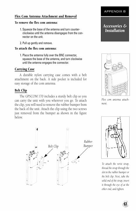
Flex Com Antenna Attachment and Removal
To remove the flex com antenna:
1. Squeeze the base of the antenna and turn counter-clockwise until the antenna disengages from the con-nector on the unit.
2. Pull up gently and remove.
To attach the flex com antenna:
1. Place the antenna fully over the BNC connector,squeeze the base of the antenna, and turn clockwiseuntil the antenna engages the connector.
Carrying Case
A durable nylon carrying case comes with a beltattachment on the back. A side pocket is included foreasy storage of the com antenna.
Belt Clip
The GPSCOM 170 includes a sturdy belt clip so youcan carry the unit with you wherever you go. To attachthe clip, you will need to remove the rubber bumper fromthe back of the unit. Attach the clip using the two screwsjust removed from the bumper as shown in the figurebelow.
Accessories &Installation
APPENDIX B
67
Belt ClipRubberBumper
To attach the wrist strap,thread the strap through theslot in the rubber bumper orthe belt clip. Next, take thesolid end of the strap, insertit through the eye of at theother end, and tighten.
Flex com antenna attach-ment.
170 manual pages rev D 9/21/98 9:23 AM Page 67

Battery Pack Removal
To remove the Ni-Cad battery pack:
1. Press down on the battery pack latch, pull down on thepack and remove.
Accessories &Installation
APPENDIX B
68
Battery PackLatch
Battery PackRemoval
170 manual pages rev D 9/21/98 9:23 AM Page 68

Trickle Charger/AC Adapter
The trickle charger/AC adapter supplied with theGPSCOM 170 converts line voltage to the DC voltagenecessary to operate the unit. The AC adapter also slow-ly recharges the Ni-Cad battery pack at a rate of 14 hoursfor a full recharge. Make sure you charge the Ni-Cad battery pack for 14 hours before using yourGPSCOM 170 to ensure optimum capacity and perfor-mance. When charging the battery pack, be sure to turnthe unit off to ensure a full charge. The cigarette lighteradapter will also trickle charge the battery pack only if theunit is turned on and in the receive mode (GPS or com).
To recharge the Ni-Cad battery pack:
1. Attach the connector end of the adapter to the GPSCOM 170 by sliding it into the slot on the left side ofthe unit (observe the keyway on the unit connector andthe matching groove on the connector end).
2. Plug the other end into an electrical outlet.
Do not charge the GPSCOM 170 for more than 24 hours. Heat generated by overcharging can shortenbattery life and cause battery pack component failures.
Battery Pack Handling and Storage
The Ni-Cad battery supplied with the GPSCOM 170has exposed terminals which may be shorted if not storedproperly. Don’t place a loose battery pack on or nearmetal objects (paper clips, keys, tools, etc.) and be care-ful when placing battery packs in handbags, toolboxes,etc. Never immerse a battery pack in water. If the batterypack becomes wet, wipe it dry before attaching it to the unit.
Always store your GPSCOM 170 with the batterypack installed. An internal lithium battery will savealmanac and waypoint data for an extended period oftime, but it is designed to allow you to recharge the bat-tery pack, not replace it. If you’re storing the unit for theseason, make sure the batteries are fully charged.
Accessories &Installation
APPENDIX B
69
WARNING!
Do not dispose of a Ni-Cadbattery pack in a fire orincinerator. Heat may causebattery cells to explodeand/or release dangerousgases. All batteries must berecycled or disposed ofproperly, and cannot be dis-posed of by ordinary wastedisposal methods. Pleasetake the time to check withyour nearest GARMIN ser-vice center for proper dis-posal methods and locations.
!#
170 manual pages rev D 9/21/98 9:23 AM Page 69

Receive160.650156.050160.700160.750156.150160.800156.200160.850156.250156.300160.950156.350156.400156.450156.500156.550156.600156.650156.700156.750156.800156.850161.500156.900161.550156.950161.600161.650157.050161.700157.100161.750157.150161.800161.850161.900161.950162.000160.625160.675156.075160.725
Frequency (MHz)
70
Channel List
APPENDIX C
The GPSCOM 170 operates on the following VHF channels.
Channel Number
Transmit156.050156.050156.100156.150156.150156.200156.200156.250156.250156.300156.350156.350156.400156.450156.500156.550156.600156.650 156.700156.750156.800156.850156.900156.900156.950156.950157.000157.050157.050157.100157.100157.150157.150157.200157.250157.300156.350157.400156.025156.075156.075156.125
INT01
0203
04
05
0607
0809101112131415161718
19
2021
22
23
24252627286061
62
USA
01A
03A
05A06
07A08091011121314151617
18A
19A20
21A
22A
23A2425262728
61A
CAN01
0203
04A
05A06
07A08091011121314151617
18A
19A20
21A
22A23
242526272860
Important!
• Channel 13: 1 W
initial USA.
• Channel 15: No trans-
mit USA or INT; 1W
Canada.
• Channel 17: 1W all
bands.
• Channel 20: 1W
Canada.
• Channels 03A and
61A are not
authorized for use by
the general public in
U. S. waters.
170 manual pages rev D 9/21/98 9:23 AM Page 70

WX Channels - Receive Only
71
Channel List
APPENDIX C
Channel Number Frequency (MHz)
Transmit156.125156.175156.175156.225156.225156.275156.275156.325156.325156.375156.425156.475NO TX156.575156.625156.675156.725156.875156.925156.925156.975156.975157.025157.025157.075157.075157.125157.125157.175157.175157.225157.275157.325157.375157.425157.425
Receive156.125160.775156.175160.825156.225160.875156.275160.925156.325156.375156.425156.475156.525156.575156.625156.675156.725156.875161.525156.925161.575156.975161.625157.025161.675157.075161.725157.125161.775157.175161.825161.875161.925161.975162.025157.425
INT
63
64
65
66
67686970717273747778
79
80
81
82
83
8485868788
USA
63A
64A
65A
66A676869707172737477
78A
79A
80A
81A
82A
83A8485868788
88A
CAN62A
6464A
65A
66A676869707172737477
78A
79A
80A
81A
82A83
83A8485868788
WX6 162.500WX7 162.525WX8 161.650WX9 161.850WX10 162.000
Important!
• Channel 66A: 1W
Canada.
• Channel 77: 1W
initial Canada and
USA.
• Channels 64A, 81A,
and 83A are not
authorized for use by
the general public in
U.S. waters.
WX1 162.550WX2 162.400WX3 162.475WX4 162.425WX5 162.450
170 manual pages rev D 9/21/98 9:23 AM Page 71

The GPSCOM 170 is constructed of high-quality materials andshould not require user maintenance. Should your unit ever needrepair, please take it to an authorized GARMIN service center. TheGPSCOM 170 has no user-serviceable parts. Never attempt anyrepairs yourself. To protect your GPSCOM 170, keep it in its carry-ing case when not in use, and never allow gasoline or other solventsto come into contact with the case. Clean the case and lens with asoft cloth and a household window cleaner.
PHYSICAL
Size: 7.1”H x 2.3”W x 1.4”D (18 x 5.8 x 3.6 cm)
Weight: Approx 1.4 lbs. (.63Kg)
Temperature Range: 5º to 158ºF (-15º to 70ºC)
PERFORMANCE
GPS: Receiver: PhaseTrac12
Acquisition Time: Approx. 15 seconds (warm start)
Approx. 45 seconds (cold start)
Approx. 5 minutes (AutoLocate)
Update Rate: 1/second, continuous
Position Accuracy: 1-5 meters (16-33 ft.) with DGPS corrections*
15 meters (49 ft.) RMS**
Velocity Accuracy: 0.1 knot RMS steady state, 99 knots max
Dynamics: Performs to specification to 6g’s
Transceiver: Frequency Bands: All U.S., Canadian, and International marine chan-nels, plus 10 weather frequencies
Selectivity: Adjacent channel selectivity, 65dB
Spurious Image Response, 65dB
Sensitivity (FM): > 12 dB SINAD at .3 microvolt
(WX): > 12 dB SINAD at .3 microvolt
Specifications subject to change without notice.
* With optional GARMIN GBR 21 Beacon Receiver Input.
** Subject to accuracy degradation to 100m 2DRMS under the US DOD-imposed Selective Availability Program.
Specifications
APPENDIX D
72
170 manual pages rev D 9/21/98 9:23 AM Page 72

Transceiver Specifications (continued):
Channel Spacing: 25 kHz
Audio Power: 0.5 W into 16 ohm speaker
Audio Distortion: < 10%
Transmitter Output: 1 watt low/5 watts high
Sidetone Audio Power: 7 vPP across 330 ohm load
Frequency Stability: +/- 10 PPM
Duty Cycle: No damage even if continuously keyed
Microphone: Internal electret or optional external mic/headset
Compliance: FCC Part 87
POWER
Source: (1) 7.2v, 1800 mAh Ni-Cad battery pack, or 9-33 VDC external.
Battery Life:*** 6 hours (low) and 4 hours (high); GPS/COM (GPSonly 10 hours).
Current Consumption: Standby - 150 mA, GPS on, Com Off.
Receive - 240 mA; GPS on, Com Rx.
Transmit - 2.4 A (High Power), 1.3 A (Low Power)
***Based on ratio of 5% transmit, 5% receive, and 90% standby
Specifications
APPENDIX D
73
170 manual pages rev D 9/21/98 9:23 AM Page 73

Accuracy has been Degraded—The accura-cy of the receiver has been degraded beyond500 meters due to poor satellite geometry ordata quality. You should check other naviga-tional sources to verify the position indicated.
Active Waypoint Can’t Be Deleted—Youhave attempted to change the ‘Active To’ or‘Active From’ waypoint. Clear the active routeor GOTO before making your changes.
Already Exists—The name you are enteringalready exists in memory.
Battery Power is Low—The Ni-Cad batteryis low and should be recharged.
Battery Power is too Low to Transmit—Battery power is too low to allow transmitting.
COM Failed—The VHF com has failed. Takethe unit to an authorized service center.
GPS and COM Turned Off—The GPS andCom functions are turned off due to low bat-tery voltage.
Leg Not Smoothed—The upcoming route legis too short for smooth waypoint transitions.
Need 2D Altitude—The unit needs altitudeinput in order to start and/or continue 2D nav-igation.
No DGPS Position—Not enough data isavailable to compute a DGPS position.
No RTCM Input—The beacon receiver isimproperly connected or baud rates do notmatch.
Oscillator Needs Adjustment—The unit hasdetected excessive drift in its internal crystaloscillator which may result in longer acquisi-tion time. Take the unit to an authorized ser-vice center.
Poor GPS Coverage—The unit cannotacquire the necessary number of satellites tocompute a position. Try another location witha clearer view of the sky.
Power Down and Re-init—The unit is notable to calculate a position due to abnormalsatellite conditions. Turn the unit off and veri-fy the last position shown by other means. Trythe unit again later, possibly in a different loca-tion.
Read Only Mem has Failed—The perma-nent memory has failed and the unit is notoperable. Take the unit to an authorized ser-vice center.
Received an Invalid WPT—A waypoint wasreceived during upload transfer that has aninvalid identifier.
Route Waypoint Can’t be Deleted—Thewaypoint you are trying to delete is part of aroute. Delete the waypoint from the routebefore removing it from memory.
Receiver has Failed—A failure in receiverhardware has been detected. If this messagepersists, take the unit to an authorized dealer.
Route is Full—You have attempted to addmore than 30 waypoints to a route.
The GPSCOM 170 uses a flashing on-screen message indicator to alert you to important information. Whenever themessage indicator appears, press P to view the messagepage. There are two types of messages: temporary alerts andcondition alerts. Temporary alerts are cleared from the messagepage after viewing, while condition alerts remain until the con-dition has been resolved. Pay careful attention to all messagesfor your own safety.
Messages
APPENDIX E
74
170 manual pages rev D 9/21/98 9:23 AM Page 74

Messages
APPENDIX E
Route is not Empty—You have attempted to copyinto a route already in use.
RTCM Input has Failed—DGPS data beingreceived has been lost. You are no longer receivingthe beacon signal.
Searching the Sky—The unit is searching the skyfor almanac data or the unit is in AutoLocate mode.
Stuck PTT—The unit is continuously transmit-ting due to a stuck microphone condition.
Stored Data was Lost—All waypoints, routes,time and almanac data has been lost due to batteryfailure or clearing the receiver’s memory.
Transfer has been Completed—The receiver isfinished uploading or downloading information tothe connected device.
Weather Alert Tone Detected—The unit hasdetected the NOAA severe weather tone.
WPT Memory is Full—You have used all 250waypoints. Delete unwanted waypoints to makeroom for new entries.
75
170 manual pages rev D 9/21/98 9:23 AM Page 75

The following list shows the map datums available forthe GPSCOM 170. Menu page abbreviations are listedfirst, followed by the corresponding map datum nameand area. The default map datum for the GPSCOM 170 isWGS 84.
Map Datums
APPENDIX F
Adindan Adindan- Ethiopia, Mali, Senegal,Sudan
Afgooye Afgooye- Somalia
AIN EL ABD ‘70 AIN EL ANBD 1970- Bahrain Island,Saudi Arabia
Anna 1 Ast ‘65 Anna 1 Astro ‘65- Cocos Isl.
ARC 1950 ARC 1950- Botswana, Lesotho,Malawi, Swaziland, Zaire, Zambia,Zimbabwe
ARC 1960 ARC 1960- Kenya, Tanzania
Ascnsn Isld ‘58 Ascension Island ‘58- AscensionIsland
Astro B4 Sorol Astro B4 Sorol Atoll- Tern Island
Astro Bcn “E” Astro Beacon “E”- Iwo Jima
Astro Dos 71/4 Astro Dos 71/4- St. Helena
Astr Stn ‘52 Astronomic Stn ‘52- Marcus Island
Astrln Geod ‘66 Australian Geod ‘66- Australia,Tasmania Island
Astrln Geod ‘84 Australian Geod ‘84- Australia,Tasmania Island
Bellevue (IGN) Efate and Erromango Islands
Bermuda 1957 Bermuda 1957- Bermuda Islands
Bogata Observ Bogata Obsrvatry- Colombia
Campo Inchspe Campo Inchauspe- Argentina
Canton Ast ‘66 Canton Astro 1966- Phoenix Islands
Cape Cape- South Africa
Cape Canavrl Cape Canaveral- Florida, BahamaIslands
Carthage Carthage- Tunisia
CH-1903 CH 1903- Switzerland
Chatham 1971 Chatham 1971- Chatham Island(New Zealand)
Chua Astro Chua Astro- Paraguay
Corrego Alegr Corrego Alegre- Brazil
Djakarta Djakarta (Batavia)- Sumatra Island(Indonesia)
Dos 1968 Dos 1968- Gizo Island (New Georgia Islands)
Easter Isld 67 Easter Island 1967
European 1950 European 1950- Austria, Belgium,Denmark, Finland, France, Germany,Gibraltar, Greece, Italy, Luxembourg,Netherlands, Norway, Portugal,Spain, Sweden, Switzerland
European 1979 European 1979- Austria, Finland,Netherlands, Norway, Spain, Sweden,Switzerland
Finland Hayfrd Finland Hayford- Finland
Gandajika Base Gandajika Base- Republic of Maldives
Geod Datm ‘49 Geodetic Datum ‘49- New Zealand
Guam 1963 Guam 1963- Guam Island
Gux 1 Astro Gux 1 Astro- Guadalcanal Island
Hjorsey 1955 Hjorsey 1955- Iceland
Hong Kong ‘63 Hong Kong ‘63- Hong Kong
Hu-Tzu-Shan Hu-Tzu-Shan- Taiwan
Indian Bngldsh Indian- Bangladesh, India, Nepal
Indian Thailand Indian- Thailand, Vietnam
Indonesia ‘74 Indonesia 1974- Indonesia
Ireland 1965 Ireland 1965- Ireland
ISTS 073 Astro ISTS 073 ASTRO ‘69- Diego Garcia
Johnston Island Johnston Island KandawalaKandawala- Sri Lanka
Kerguelen Islnd Kerguelen Island
Kertau 1948 Kertau 1948- West Malaysia,Singapore
L. C. 5 Astro Cayman Brac Island
Liberia 1964 Liberia 1964- Liberia
Luzon Mindanao Luzon- Mindanao Island
Luzon Philippine Luzon- Philippines (excluding Mindanao Island)
Mahe 1971 Mahe 1971- Mahe Island
Marco Astro Marco Astro- Salvage Island
Massawa Massawa- Eritrea (Ethiopia)
Merchich Merchich- Morocco
Midway Ast ‘61 Midway Astro ‘61- Midway
Minna Minna- Nigeria
76
170 manual pages rev D 9/21/98 9:23 AM Page 76

NAD27 Alaska North American 1927- Alaska
NAD27 Bahamas North American 1927- Bahamas (excluding San SalvadorIsland)
NAD27 Canada North American 1927- Canada andNewfoundland
NAD27 Canal Zone North Am. 1927- Canal Zone
NAD27 Caribbn North American 1927- Caribbean(Barbados, Caicos Islands, Cuba,Dom. Rep., Grand Cayman, Jamaica, Leeward and Turks Islands)
NAD27 Central North American 1927- CentralAmerica (Belize, Costa Rica, ElSalvador, Guatemala, Honduras,Nicaragua)
NAD27 CONUS North Am. 1927- Mean Value
NAD27 Cuba North American 1927- Cuba
NAD27 Grnland North American 1927- Greenland (Hayes Peninsula)
NAD27 Mexico N. American 1927- Mexico
NAD27 San Sal North American 1927- San SalvadorIsland
NAD83 North American 1983- Alaska,Canada, Central America, CONUS,Mexico
Nhrwn Masirah Nahrwn- Masirah Island (Oman)
Nhrwn Saudi A Nahrwn- Saudi Arabia
Nhrwn United A Nahrwn- United Arab Emirates
Naparima BWI Naparima BWI- Trinidad andTobago
Obsrvtorio ‘66 Observatorio 1966- Corvo and Flores Islands (Azores)
Old Egyptian Old Egyptian- Egypt
Old Hawaiian Old Hawaiian- Mean Value
Oman Oman- Oman
Ord Srvy GB Old Survey Grt Britn- England, Isleof Man, Scotland, Shetland Isl.,Wales
Pico De Las Nv Canary Islands
Ptcairn Ast ‘67 Pitcairn Astro ‘67- Pitcairn Isl.
Prov S Am ‘56 Prov So Amricn ‘56- Bolivia,Chile,Colombia, Ecuador, Guyana,Peru, Venezuela
Prov S Chln ‘63 Prov So Chilean ‘63- S. Chile
Puerto Rico Puerto Rico & Virgin Islands
Qatar National Qatar National- Qatar
Qornoq Qornoq- South Greenland
Reunion Reunion- Mascarene Island
Rome 1940 Rome 1940- Sardinia Island
RT 90 Sweden
Santo (Dos) Santo (Dos)- Espirito Santo Island
Sao Braz Sao Braz- Sao Miguel, Santa Maria Islands (Azores)
Sapper Hill ‘43 Sapper Hill 1943- East FalklandIsland
Schwarzeck Schwarzeck- Namibia
Sth Amrcn ‘69 South American ‘69- Argentina,Bolivia, Brazil, Chile, Colombia,Ecuador, Guyana, Paraguay, Peru, Venezuela, Trinidad and Tobago
South Asia South Asia- Singapore
SE Base Southeast Base- Porto Santo and Madiera Islands
SW Base Southwest Base- Faial, Graciosa,Pico, Sao Jorge and Terceira Islands(Azores)
Timbalai 1948 Timbalai 1948- Brunei and E.Malaysia (Sarawak and Sabah)
Tokyo Tokyo- Japan, Korea, Okinawa
Tristan Ast ‘68 Tristan Astro 1968- Tristan daCunha
Viti Levu 1916 Viti Levu 1916- Viti Levu/ FijiIslands
Wake-Eniwetok Wake-Eniwetok- Marshall Isl.
WGS 72 World Geodetic System 1972
WGS 84 World Geodetic System 1984
Zanderij Zanderij- Surinam
Map Datums
APPENDIX F
77
170 manual pages rev D 9/21/98 9:23 AM Page 77

Time Offset Chart
Reference the table below to find the UTC-to-localtime offset for your longitudinal zone. If you are in a day-light savings time zone, add one hour to the offset. Forexample, if you are at longitude W081.0º00.00’ and UTCtime is 16:00, local time is 11:00 standard time. The timezone boundaries given below may be different dependingon your area. Consult your charts for more accurateinformation concerning time zones.
Longitudinal Zone Offset
W180.0º to W172.5º -12
W172.5º to W157.5º -11
W157.5º to W142.5º -10
W142.5º to W127.5º -9
W127.5º to W112.5º -8
W112.5º to W097.5º -7
W097.5º to W082.5º -6
W082.5º to W067.5º -5
W067.5º to W052.5º -4
W052.5º to W037.5º -3
W037.5º to W022.5º -2
W022.5º to W007.5º -1
W007.5º to E007.5º 0
Longitudinal Zone Offset
E007.5º to E022.5º 1
E022.5º to E037.5º 2
E037.5º to E052.5º 3
E052.5º to E067.5º 4
E067.5º to E082.5º 5
E082.5º to E097.5º 6
E097.5º to E112.5º 7
E112.5º to E127.5º 8
E127.5º to E142.5º 9
E142.5º to E157.5º 10
E157.5º to E172.5º 11
E172.5º to E180.0º 12
TIme OffsetChart
APPENDIX G
78
170 manual pages rev D 9/21/98 9:23 AM Page 78

A
Accessories . . . . . . . . . . . . . . . . . . . .67Acquiring Satellites . . . . . . . . . . . .6, 66Activating a Route . . . . . . . . . . . . . . .45Active Route Page . . . . . . . . . . . . . . .46Altitude Display . . . . . . . . . . . . . . . . .21Antenna Height . . . . . . . . . . . . . . . . .33
B
Battery Pack . . . . . . . . . . . . . . . .68, 69Battery Voltage Indicator . . . . . . . . . .20Belt Clip . . . . . . . . . . . . . . . . . . . . . .67Active Route Page . . . . . . . . . . . . . . .46Altitude Display . . . . . . . . . . . . . . . . .21Antenna Height . . . . . . . . . . . . . . . . .33
C
CDI Scale Setup . . . . . . . . . . . . . . . . .59Calling Channel . . . . . . . . . . . . . . . . .32Carrying Case . . . . . . . . . . . . . . . . . .67Cautions . . . . . . . . . . . . . . . . . . . . . . .ivChannel Definition Page . . . . . . . . . .36Channel List . . . . . . . . . . . . . . . . .70-71Channel Lockout . . . . . . . . . . . . . . . .37Com Setup Page . . . . . . . . . . . . . . . .29Compass Page . . . . . . . . . . . . . . .12, 50Copying and Clearing Routes . . . . . . .44
D
DGPS Interface . . . . . . . . . . . . . . . . .62Data Entry . . . . . . . . . . . . . . . . . . . . . .8Date and Time Setup . . . . . . . . . . . . .57Deleting Waypoints . . . . . . . . . . . . . .24Distance and Sun Calculations . . . . . .56Dual Watch . . . . . . . . . . . . . . . . . . . .17
E
EZinit . . . . . . . . . . . . . . . . . . . . . . . .65Editing Waypoints . . . . . . . . . . . . . . .27Editing Routes . . . . . . . . . . . . . . . . . .46Environment Canada . . . . . . . . . . . . .16Estimated Time Enroute (ETE) . . . . . .11
F
FCC . . . . . . . . . . . . . . . . . . . . . . . . . .iiFlex Antenna . . . . . . . . . . . . . . . . . . .67
G
GOTO . . . . . . . . . . . . . . . . . . . . . . .10GPS Pages . . . . . . . . . . . . . . . . . . . . .13
H
Highway Page . . . . . . . . . . . . . . . . . .11
I
Initializing the Receiver . . . . . . . . . . .64Interface Setup . . . . . . . . . . . . . . . . .61
K
Keys and Controls . . . . . . . . . . . . . . . .4
M
Map GOTO . . . . . . . . . . . . . . . . . . . .53Magnetic Heading . . . . . . . . . . . . . . .60MOB . . . . . . . . . . . . . . . . . . . . . . . . .39Managing the Track Log . . . . . . . . . . .55Map Datums . . . . . . . . . . . . . . . .55, 74Map Page . . . . . . . . . . . . . . . . . . . . . .9Map Setup Page . . . . . . . . . . . . . . . . .54Maritime Radio User’s Guide . . . . . . .14MOB . . . . . . . . . . . . . . . . . . . . . . . . .39Map Page . . . . . . . . . . . . . . . . . . . . . .9Marine Radio License . . . . . . . . . . . . . .2Marking a Position . . . . . . . . . . . . . . .8Marking a Waypoint . . . . . . . . . . . . .53Memory Bank Page . . . . . . . . . . . . . .34
Index
APPENDIX H
79
170 manual pages rev D 9/21/98 9:23 AM Page 79

M
Memory List Editing . . . . . . . . . . . . .35Memory Page . . . . . . . . . . . . . . . . . .37Menu Page . . . . . . . . . . . . . . . . . . . .59Message Page . . . . . . . . . . . . . . . .12, 56Messages . . . . . . . . . . . . . . . . . . .74, 75Moving Map Page . . . . . . . . . . . .10, 51
N
NMEA Interface . . . . . . . . . . . . . . . . .61National Weather Service . . . . . . . . . .16Navigation Guidance Page . . . . . . . . .48Navigation Setup . . . . . . . . . . . . . . . .59Navigation Simulator . . . . . . . . . . . . .63Nearest Waypoint Page . . . . . . . . . . .23Ni-Cad Battery Pack . . . . . . . . . . . .6, 69
O
On-Route GOTO’s . . . . . . . . . . . . . . .47
P
Packing List . . . . . . . . . . . . . . . . . . . . .iiPanning Function . . . . . . . . . . . . . . .52Poor GPS Coverage . . . . . . . . . . . . . .19Position Format . . . . . . . . . . . . . . . . .59Position Page . . . . . . . . . . . . . . . . .7, 21Power Override . . . . . . . . . . . . . . . . .38Powering Up . . . . . . . . . . . . . . . . . . . .6Priority Scan . . . . . . . . . . . . . . . . . . .31
R
Range Rings . . . . . . . . . . . . . . . . . . .51Receiver Status . . . . . . . . . . . . . . . . .19Reference Waypoints . . . . . . . . . . . . .26Renaming Waypoints . . . . . . . . . . . . .27Route Navigation . . . . . . . . . . . . . . . .42
S
Satellite Status Page . . . . . . . . . . . .6, 18Scan Timeout . . . . . . . . . . . . . . . . . .32Scanning Modes and Setup . . . . . . . .31Scanning Waypoints . . . . . . . . . . . . .28Screen Backlighting and Contrast . . . .50Selecting Channel 16/9 . . . . . . . . . . .16Selecting Map Scales . . . . . . . . . . . . .52Selecting a Channel . . . . . . . . . . . . . .14Selecting a GOTO Destination . . . . . .39Selecting a Weather Channel . . . . . . .16Selecting an Operating Band . . . . . . .32Signal Strength Bars . . . . . . . . . . . . . .18Simulator Mode . . . . . . . . . . . . . . . . .63Sky View . . . . . . . . . . . . . . . . . . . . . .18Specifications . . . . . . . . . . . . . . . .72, 73Speed, Track, and Position . . . . . . . . .63System Setup . . . . . . . . . . . . . . . . . . .57
T
Time Format . . . . . . . . . . . . . . . . . . .50Time Offset . . . . . . . . . . . . . . . . . . . .67Time Offset Chart . . . . . . . . . . . . . . .78Tips on Transmitting . . . . . . . . . . . . .15Tips on Using TracBack . . . . . . . . . . .41Tone Settings . . . . . . . . . . . . . . . . . . .50TracBack . . . . . . . . . . . . . . . . . . . . . .40Track Log Display . . . . . . . . . . . . . . .55Track Log Setup Page . . . . . . . . . . . . .54Track Method . . . . . . . . . . . . . . . . . .55Track Setup Window . . . . . . . . . . . . .54Transmitting . . . . . . . . . . . . . . . . . . .15Tri Watch . . . . . . . . . . . . . . . . . . . . .30Trickle Charger . . . . . . . . . . . . . . . . .69Trip Odometer . . . . . . . . . . . . . . . . . .21
U
Unit Description . . . . . . . . . . . . . . . . .2Units of Measure . . . . . . . . . . . . . . . .60Using the Compass Page . . . . . . . . . .50Using the Highway Page . . . . . . . . . .49Using the VHF Transceiver . . . . . . . . .14
Index
APPENDIX H
80
170 manual pages rev D 9/21/98 9:23 AM Page 80

V
VHF Communication Pages . . . . . . . .29VHF Line-of-Sight . . . . . . . . . . . . . . .33VHF Status Field . . . . . . . . . . . . . . . . .7
W
Warranty . . . . . . . . . . . . . . . . . . . . . .80Waypoint Comments . . . . . . . . . . . . .27Waypoint Definition Page . . . . . . . . . .25Waypoint List Page . . . . . . . . . . . . . .24Waypoint Submenus . . . . . . . . . . . . .23Waypoints . . . . . . . . . . . . . . . . . . . . .22Weather Alert Page . . . . . . . . . . . . . .30Welcome Page . . . . . . . . . . . . . . . . . .64Wrist Strap . . . . . . . . . . . . . . . . . . . .67
Z
Zooming and Panning . . . . . . . . . . . .52
Index
APPENDIX H
81
170 manual pages rev D 9/21/98 9:23 AM Page 81

LIMITED WARRANTYGARMIN Corporation warrants this product to be free from defects in materials
and workmanship for one year from the date of purchase. GARMIN will, at its soleoption, repair or replace any components which fail in normal use. Such repairs orreplacement will be made at no charge to the customer for parts or labor. The cus-tomer is, however, responsible for any transportation costs. This warranty does notcover failures due to abuse, misuse, accident or unauthorized alteration or repairs.GARMIN assumes no responsibility for special, incidental, punitive or consequentialdamages, or loss of use.
The warranties and remedies contained herein are exclusive and in lieu of allother warranties expressed or implied, including any liability arising under warran-ty of merchantability or fitness for a particular purpose, statutory or otherwise. Thiswarranty gives you specific legal rights, which may vary from state to state.
To obtain warranty service, call the GARMIN Customer Service department (913-397-8200) for a returned merchandise tracking number. The unit should besecurely packaged with the tracking number clearly marked on the outside of thepackage, and sent freight prepaid and insured to a GARMIN warranty service station.A copy of the original sales receipt is required as the proof of purchase for warrantyrepairs. GARMIN reatins the exclusive right to repair or replace the unit or softwareat its sole discretion.
170 manual pages rev D 9/21/98 9:23 AM Page 82

© 1997 GARMIN CORPORATION
1200 E. 151st Street, Olathe, KS USA 66062
GARMIN (Europe) Ltd.Unit 5, The Quadrangle, Abbey Park Industrial Estate, Romsey, SO51 9AQ U.K
Part Number 190-00093-00 Rev. D
®
170 cover 9/21/98 9:31 AM Page 4