170 (tm50) parts manual...170 (tm50) illustrated parts manual [email protected] manuel illustré de...
TRANSCRIPT
170TM50
illustrated parts manualManuel illustré de pièces détachées
Illustrierte Stückliste
Manual de piezas ilustrado
M50150/08
Issue 8(November 2010)

170 (TM50)illustrated parts manual
Manuel illustré de pièces détachées Illustrierte Stückliste Manual de piezas ilustrado
iiiissue 08
Please Note, at the time of going to press, all information, illustrations details and descriptions contained herein are valid. Niftylift reserves the right to change, alter, modify or improve its products without any obligation to install them on previously manufactured machines.
Readers of this manual requiring further information should contact us at:
Niftylift Ltd. Niftylift Inc.Fingle Drive 32 Concourse WayStonebridge GreerMilton Keynes SC 29651MK13 OER USAUnited Kingdom
Tel +44 (0)1908 857899 1 864 968 8881Fax +44 (0)1908 227460 1 864 968 8836
Ordering of PartsWhen ordering a replacement part for your Niftylift product, please state the following:
• Machine Model and Serial number Niftylift Part number
• Full description of the part Quantity required
• Purchase Order number Destination address
Machine Information
Model number. . . . . . . . . . . . . . . . . . . . . . . . . . . . . Date of Purchase. . . . . . . . . . . . . .
Serial number . . . . . . . . . . . . . . . . . . . . . . . . . . . . .
Veuillez noter qu'au moment de la mise sous presse, l'ensemble des informations, illustrations, détails et descriptions, contenus dans le présent document, sont valides. Niftylift se réserve le droit de changer ou d'améliorer ses produits sans obligation de montage sur les anciennes machines.
Pour toutes informations supplémentaires, veuillez nous contacter à:
Niftylift Ltd. Niftylift Inc.Fingle Drive 32 Concourse WayStonebridge GreerMilton Keynes SC 29651MK13 OER USAUnited Kingdom
Tel +44 (0)1908 857899 1 864 968 8881Fax +44 (0)1908 227460 1 864 968 8836
Commande de piècesLors de la commande de pièces de rechange pour votre machine Niftylift, veuillez indiquer ce qui suit:
• Modèle et numéro de série de la machine Référence de la pièce Niftylift
• Description complète de la pièce Quantité requise
• Numéro de commande Adresse de destination
Informations relatives à la machine
Numéro de modèle . . . . . . . . . . . . . . . . . . . . . . . . . . . Date d'achat . . . . . . . . . . . . . . . . . . .
Numéro de série . . . . . . . . . . . . . . . . . . . . . . . . . . . . .

170 (TM50)
iv
illustrated parts manual Manuel illustré de pièces détachées Illustrierte Stückliste Manual de piezas ilustrado
issue 08
Bitte nehmen Sie zur Kenntnis, dass alle hierin enthaltenen Informationen, Illustrationen und Beschreibungen zum Zeitpunkt des Drucks gültig sind. Niftylift behält sich das Recht vor, Produkte zu wechseln, ändern, modifizieren und zu verbessern, ohne verpflichtet zu sein, sie an früher gefertigten Maschinen zu installieren.Wenn Leser dieser Anleitung weitere Informationen benötigen, wenden sie sich bitte an uns unter:
Niftylift Ltd. Niftylift Inc.Fingle Drive 32 Concourse WayStonebridge GreerMilton Keynes SC 29651MK13 OER USAGroßbritannien
Tel +44 (0)1908 857899 1 864 968 8881Fax +44 (0)1908 227460 1 864 968 8836
Bestellen von ErsatzteilenBei der Bestellung eines Ersatzteils für Ihr Produkt von Niftylift geben Sie bitte folgende Einzelheiten an:
• Maschinenmodell und Seriennummer Niftylift Art.-Nr.
• Ausführliche Beschreibung des Teils Erforderliche Menge
• Bestellnummer Bestimmungsadresse
Maschineninformationen
Modellnummer . . . . . . . . . . . . . . . . . . . . . . . . . . . . . . Kaufdatum . . . . . . . . . . . . . . . . . . . .
Seriennummer . . . . . . . . . . . . . . . . . . . . . . . . . . . . . . .
Por favor, observe que en el momento de pasar a imprenta, toda la información, ilustraciones y descripciones contenidas en el presente documento eran válidas. Niftylift se reserva el derecho de cambiar, alterar, modificar o mejorar sus productos, sin obligación alguna de instalar dichos cambios en máquinas fabricadas anteriormente.Los usuarios de este manual que requieran más información, deberán ponerse en contacto con nosotros en:
Niftylift Ltd. Niftylift Inc.Fingle Drive 32 Concourse WayStonebridge GreerMilton Keynes SC 29651MK13 OER USAUnited Kingdom
Tel +44 (0)1908 857899 1 864 968 8881Fax +44 (0)1908 227460 1 864 968 8836
Pedido de piezasAl realizar el pedido de una pieza de recambio para su producto Niftylift, sírvase especificar lo siguiente:
• Modelo y número de serie de la máquina Número de pieza Niftylift
• Descripción completa de la pieza Cantidad requerida
• Número de orden de compra Dirección de destino
Información de la máquina
Número de modelo . . . . . . . . . . . . . . . . . . . . . . . . . . . Fecha de compra . . . . . . . . . . . . . .
Número de serie . . . . . . . . . . . . . . . . . . . . . . . . . . . . .

Parts Order Form (make copies for use)
Bon de commande de pièces (Faire des photocopies pour vos commandes ultérieures) tel +44 (0)1908 857899Bestellformular für Ersatzteile (bitte Kopien zur zukünftigen Verwendung machen) fax +44 (0)1908 227460Impreso de pedido de piezas (haga copias para el uso) www.niftylift.com
Note; If items have decals/labels attached, these are not included (unless stated otherwise), they must be ordered separately using the part (P) number printed on the decal.
Remarque : si les composants sont dotés d'autocollants/étiquettes, ceux-ci ne sont pas inclus (sauf avis contraire). Ils doivent être commandés séparément en indiquant le numéro de référence (P) imprimé sur l'autocollant.
Anmerkung: Wenn an Gegenständen Klebebilder/Etiketten angebracht sind, sind diese (sofern nicht anders angegeben) nicht en-thalten und müssen separat mit Hilfe der auf den Klebebildern abgedruckten Teilenummern (P) bestellt werden.
Nota: Si los artículos llevan acopladas calcomanías/etiquetas, éstas no se incluirán (a menos que se indique lo contrario); deberán pedirse por separado utilizando el número de pieza (P) impreso en la calcomanía.
Alternatively, details of your order can be emailed to [email protected], le détail de votre commande peut nous être envoyé par email à [email protected] Alternative können Sie Ihre Bestellung auch an [email protected] sendenAlternativamente, los detalles de su pedido pueden enviarse por e-mail a [email protected]
Part NumberRéférence pièce
Art.-Nr.Número de pieza
descriptiondescription
beschreibungdescripción
quantityquantitémenge
cantidad
priceprix
preisprecio
P
P
P
P
P
P
P
P
name nom name nombre
address adresse adresse dirección
telephone téléphone tel.-Nr. teléfono
fax fax-Nr.
email e-mail
date date datum fecha
delivery addressadresse de livraisonlieferadressedirección de entrega
purchase order numbernuméro de commandebestellnummernúmero de orden de compra

170 (TM50)
vi
illustrated parts manual Manuel illustré de pièces détachées Illustrierte Stückliste Manual de piezas ilustradoco
nten
tsta
ble
des
mat
ière
sin
hal
tsve
rzei
chni
sta
bla
del
co
nten
ido
issue 08
1 chassis page
1.1 Base assembly (Hydraulic).................................................................................... 1-2
1.2 Base assembly (Manual) ....................................................................................... 1-6
1.3 Traction drive assembly....................................................................................... 1-10
1.4 Stabiliser assembly.............................................................................................. 1-14
1.5 Manual jack assembly ......................................................................................... 1-16
1.6 Tow coupling assembly....................................................................................... 1-18
1.7 Heavy duty jockey wheel..................................................................................... 1-20
1.8 Lighting assemblies............................................................................................. 1-22
1.9 Wheel hub assembly ........................................................................................... 1-24
1.10 Wheel hub assembly (Traction drive).................................................................. 1-26
1.11 Valve block (Traction drive) ................................................................................. 1-28
1.12 Auto power inlet unit ........................................................................................... 1-30
2 superstructure page
2.1 Power tray (Petrol/diesel/bi-energy)...................................................................... 2-2
2.2 Power tray (AC/Mains)........................................................................................... 2-6
2.3 Slew assembly ....................................................................................................... 2-8
2.4 Control valve assembly (3 spool) ........................................................................ 2-10
2.5 Control valve assembly (4 spool) ........................................................................ 2-12
2.6 Button box assemblies (Base)............................................................................. 2-14
2.7 Control box .......................................................................................................... 2-16
2.8 Diesel box ............................................................................................................ 2-18
2.9 AC transformer box.............................................................................................. 2-20
2.10 DC Power pack.................................................................................................... 2-22
2.11 DC Power pack (Traction Drive) ......................................................................... 2-24
2.12 AC Power pack .................................................................................................... 2-26
2.13 Diesel engine (Kubota OC60).............................................................................. 2-28
2.14 Anderson connector ............................................................................................ 2-30
3 boom assemblies page
3.1 Upper boom assembly .......................................................................................... 3-2
3.2 Lower boom assembly ......................................................................................... 3-6
3.3 Lift cylinder............................................................................................................. 3-8
3.4 Levelling cylinder ................................................................................................. 3-10
3.5 Telescope cylinder............................................................................................... 3-12
3.6 Levelling valve...................................................................................................... 3-14
4 cage page
4.1 Swivel cage assembly ........................................................................................... 4-2
4.2 Non-swivel cage assembly.................................................................................... 4-4
4.3 Cage assembly (Fibreglass) ................................................................................. 4-6

170 (TM50)illustrated parts manual
vii
Manuel illustré de pièces détachées Illustrierte Stückliste Manual de piezas ilustrado
cont
ents
tab
le d
es m
atiè
res
inh
alts
verz
eich
nis
tab
la d
el c
ont
enid
o
issue 08
4.4 Swivel cage weigh assembly (Spring)................................................................... 4-8
4.5 Swivel cage weigh assembly (Load cell)............................................................. 4-10
4.6 Non-swivel cage weigh assembly (Spring) ......................................................... 4-12
4.7 Non-swivel cage weigh assembly (Load cell) ..................................................... 4-14
4.8 Control valve assembly........................................................................................ 4-16
4.9 Button box assemblies (Cage) ............................................................................ 4-18
5 labelling page
5.1 Label locations 170 ................................................................................................ 5-2
5.2 Label locations TM50 (USA) ................................................................................ 5-14
6 hoses page
6.1 Hose kit 170 (TM50)............................................................................................... 6-2
Figures page
1.1 Base assembly (Hydraulic) ............................................................... 1-3
1.2 Base assembly (Manual)................................................................... 1-5
1.3 Traction drive assembly .................................................................. 1-11
1.4 Stabiliser assembly ......................................................................... 1-15
1.5 Manual jack assembly..................................................................... 1-17
1.6 Tow coupling assembly .................................................................. 1-19
1.7 Heavy duty jockey wheel ............................................................... 1-21
1.8 Lighting assemblies ........................................................................ 1-23
1.9 Wheel hub assembly....................................................................... 1-25
1.10 Wheel hub assembly (Traction drive) ............................................. 1-27
1.11 Valve block (Traction drive)............................................................. 1-29
1.12 Auto power inlet unit ...................................................................... 1-31
2.1 Power tray (PDE)............................................................................... 2-3
2.2 Power tray (AC) ................................................................................. 2-7
2.3 Slew assembly .................................................................................. 2-9
2.4 Control valve assembly (3 spool).................................................... 2-11
2.5 Control valve assembly (4 spool).................................................... 2-13
2.6 Button box assemblies (Base) ........................................................ 2-15
2.7 Control box...................................................................................... 2-17
2.8 Diesel box........................................................................................ 2-19
2.9 AC transformer box ......................................................................... 2-21
2.10 DC power pack................................................................................ 2-23
2.11 DC power pack (Traction drive) ...................................................... 2-25
2.12 AC power pack................................................................................ 2-27
2.13 Diesel engine (Kubota OC60) ......................................................... 2-29
2.14 Anderson connector........................................................................ 2-31

170 (TM50)illustrated parts manual Manuel illustré de pièces détachées Illustrierte Stückliste Manual de piezas ilustrado
3.1 Upper boom assembly...................................................................... 3-3
3.2 Lower boom assembly ..................................................................... 3-7
3.3 Lift cylinder ........................................................................................ 3-9
3.4 Levelling cylinder............................................................................. 3-11
3.5 Telescope cylinder .......................................................................... 3-13
3.6 Levelling valve ................................................................................. 3-15
4.1 Swivel cage assembly....................................................................... 4-3
4.2 Non-swivel cage assembly ............................................................... 4-5
4.3 Cage assembly (Fibreglass) ............................................................ 4-7
4.4 Swivel cage weigh assembly (Spring) .............................................. 4-9
4.5 Swivel cage weigh assembly (Load cell) ........................................ 4-11
4.6 Non-swivel cage weigh assembly (Spring) .................................... 4-13
4.7 Non-swivel cage weigh assembly (Load cell)................................. 4-15
4.8 Control valve assembly ................................................................... 4-17
4.9 Button box assemblies (Cage)........................................................ 4-19
5.1 Label locations 170 ........................................................................... 5-3
5.2 Label locations TM50 (USA) ........................................................... 5-15
5.3 Labels 1-30 ...................................................................................... 5-26
5.4 Labels 31-47 .................................................................................... 5-27
6.1 Hose diagram.................................................................................... 6-3
Issue Records
Chapter Pages Issue Date Comments/Changes
Introduction 8 8 11/2010 Eighth issue
1 32 7 12/2011 Revisions on pages 1-2 and 1-20/21
2 32 8 04/2012 Revisions on pages 2-4, 2-6 and 2-12
3 14 7 11/2010 Seventh issue
4 20 8 11/2010 Revised for ‘level cylinder’
5 24 3 06/2010 Third issue
6 4 1 03/2003 First issue
viii issue 08
* When ordering parts for machines other than the stated serial number,it is advisable to contact the Parts Department;
United Kingdom USA
Tel +44 (0)1908 857899 1 864 968 8881Fax +44 (0)1908 227460 1 864 968 8836Email [email protected] [email protected]

170 (TM50)
1
illustrated parts manualManuel illustré de pièces détachéesIllustrierte StücklisteManual de piezas ilustrado
chassis assemblyfrench
germanspanish

170 (TM50)
1–2
chas
sis
asse
mb
lyfr
ench
ger
man
span
ish
illustrated parts manual Manuel illustré de pièces détachées Illustrierte Stückliste Manual de piezas ilustrado
issue 07
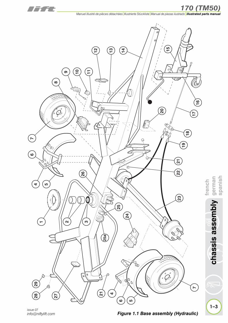
1.1 Base assembly (Hydraulic)Item Description Part Number
1 Gear wheel P10490
2 Bush (Bearing) P10489
3 Thrust washer P11642
4 Mudguard bracketLH and RH P15092
5 Mudguard P11109
6 Rubber grommet P15087
7 Wheel and tyre P11889
8
Control valveSee “Control valve assembly (4 spool)” on page 2-14
P15518
9Manual selector valve
Lever ONLYRubber gaiter
P12578P18090P19119
10 Micro switch P18937
11 Boom rest guard P10979
12 Boom clamp P11392
13 Spirit level P10228
14 Base P15832
15
Tow couplingTow coupling - USASee “Tow coupling assembly” on page 1-18
P10479P11514
16
Jockey wheelSee “Heavy duty jockey wheel” on page 1-20
P25035
17 Brake rod P10785
18 Balance bar P70080
19 Brake cable P10124
20 Terminal box P10170
170 (TM50)
fren
chg
erm
ansp
anis
hch
assi
s as
sem
bly
1–3
illustrated parts manualManuel illustré de pièces détachées Illustrierte Stückliste Manual de piezas ilustrado
issue 07
1
21
2 3
7
9 10
12
26
8
14
20
11
13
24
23
6 5
4
28 27
29
25
546
15
1716
2122
1819
7
25a
Figure 1.1 Base assembly (Hydraulic)
170 (TM50)
1–4
chas
sis
asse
mb
lyfr
ench
ger
man
span
ish
illustrated parts manual Manuel illustré de pièces détachées Illustrierte Stückliste Manual de piezas ilustrado
issue 07
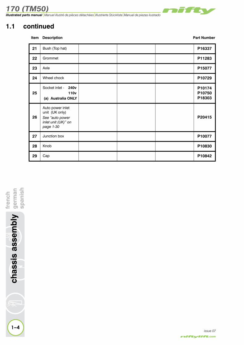
1.1 continued
Item Description Part Number
21 Bush (Top hat) P16337
22 Grommet P11283
23 Axle P15077
24 Wheel chock P10729
25Socket inlet - 240v
110v (a) Australia ONLY
P10174P10750P18303
26
Auto power inlet unit (UK only)See “auto power inlet unit (UK)” on page 1-30
P20415
27 Junction box P10077
28 Knob P10830
29 Cap P10842

170 (TM50)
fren
chg
erm
ansp
anis
hch
assi
s as
sem
bly
1–5
illustrated parts manualManuel illustré de pièces détachées Illustrierte Stückliste Manual de piezas ilustrado
issue 07Figure 1.1 Base assembly (Hydraulic)
1
21
2 3
7
9 10
12
26
8
14
20
11
13
24
23
6 5
4
28 27
29
25
546
15
1716
2122
1819
7
25a

170 (TM50)
1–6
chas
sis
asse
mb
lyfr
ench
ger
man
span
ish
illustrated parts manual Manuel illustré de pièces détachées Illustrierte Stückliste Manual de piezas ilustrado
issue 07
1.2 Base assembly (Manual)Item Description Part Number
1 Gear wheel P10490
2 Bush (Bearing) P10489
3 Thrust washer P11642
4 Mudguard bracketLH and RH P15092
5 Mudguard P11109
6 Rubber grommet P15087
7 Wheel and tyre P11889
8 Boom clamp P11392
9 Stabiliser assembly(Includes item 16) P10670
10 Spacer P10600
11 Base P10667
12
Tow couplingTow coupling - USASee “Tow coupling assembly” on page 1-18
P10479P11514
13
Jockey wheelSee “Heavy duty jockey wheel” on page 1-20
P25035
14 Brake rod P10785
15 Balance bar P70080
16
Jack assemblySee “Manual jack assembly” on page 1-16
P10666
17 Brake cable P10124
18 Axle P15077
19 Cap P10443
20 Terminal block P10187
21Socket inlet - 240v
110v (a) Australia ONLY
P10174P10750P18303

170 (TM50)
fren
chg
erm
ansp
anis
hch
assi
s as
sem
bly
1–7
illustrated parts manualManuel illustré de pièces détachées Illustrierte Stückliste Manual de piezas ilustrado
issue 07Figure 1.2 Base assembly (Manual)
12
1416
7
18
13
15
19
20
17
2121
a
8
1 2 3
4
5
4
6
6
7
9 10 11
524
25
2627
22
23
170 (TM50)
1–8
chas
sis
asse
mb
lyfr
ench
ger
man
span
ish
illustrated parts manual Manuel illustré de pièces détachées Illustrierte Stückliste Manual de piezas ilustrado
issue 07
1.2 continued
Item Description Part Number
22 Micro switch P18937
23 Locating Pin P11377
24 Spring P10003
25 Roll pin for item 23 P10669
26 Knob P10830
27 Cap P10842

170 (TM50)
fren
chg
erm
ansp
anis
hch
assi
s as
sem
bly
1–9
illustrated parts manualManuel illustré de pièces détachées Illustrierte Stückliste Manual de piezas ilustrado
issue 07Figure 1.2 Base assembly (Manual)
12
1416
7
18
13
15
19
20
17
2121
a
8
1 2 3
4
5
4
6
6
7
9 10 11
524
25
2627
22
23

170 (TM50)
1–10
chas
sis
asse
mb
lyfr
ench
ger
man
span
ish
illustrated parts manual Manuel illustré de pièces détachées Illustrierte Stückliste Manual de piezas ilustrado
issue 07
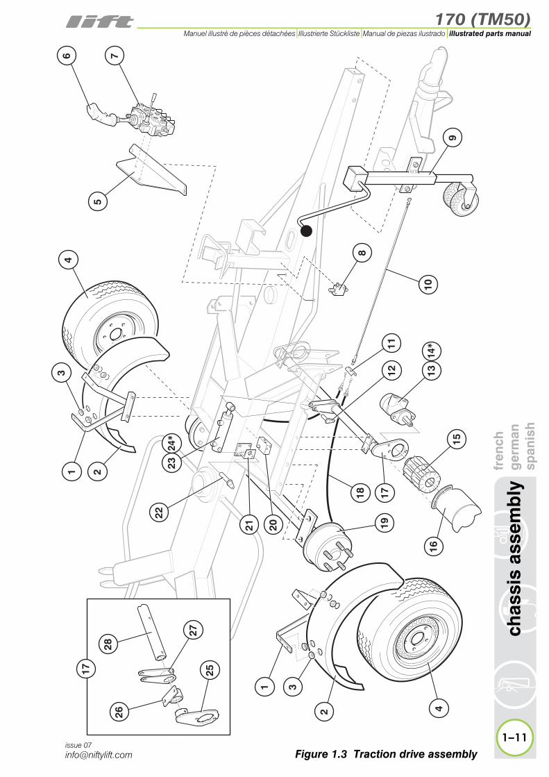
1.3 Traction drive assemblyItem Description Part Number
1 Mudguard bracket LH and RH P15413
2 Mudguard P11109
3 Rubber grommet P15087
4 Wheel and tyre P14211
5 Bracket - Valveblock P16048
6 Joystick P16125
7
ValveblockSee “Valve block (Traction drive)” on page 1-28
P14395
8Relief valveCartridge ONLY
P16548P22324
9
Jockey wheelSee “Heavy duty jockey wheel” on page 1-20
P25036
10 Brake rod - 2300mm P10785
11 Balance bar P70080
12 Pivot pin - 58mm P13870
13 Drive motor P14490
14 * Seal kit for item 13 P18428
15 Drive barrel P16074
16Cover - RH
*LHP17047P17046
17 Drive unit P15876
18 Brake cable P15058
19 Axle assembly P15305
20 Check valve P10665
21 Bracket P13868
22 Pivot pin - 83mm P13869
23 Engage cylinder P11313
24 * Seal kit for item 23 P12499
* Not illustrated
170 (TM50)
fren
chg
erm
ansp
anis
hch
assi
s as
sem
bly
1–11
illustrated parts manualManuel illustré de pièces détachées Illustrierte Stückliste Manual de piezas ilustrado
issue 07Figure 1.3 Traction drive assembly
16
6
5
7
2223
24*
14*
12
43
21
9
8
10
17
4
2021
2
31
18
13
15
1119
28
25
27
17
26

170 (TM50)
1–12
chas
sis
asse
mb
lyfr
ench
ger
man
span
ish
illustrated parts manual Manuel illustré de pièces détachées Illustrierte Stückliste Manual de piezas ilustrado
issue 07
1.3 continued
Item Description Part Number
25 Crank P13864
26 Bearing P13862
27 Pivot arm P13865
28 Shaft P14007

170 (TM50)
fren
chg
erm
ansp
anis
hch
assi
s as
sem
bly
1–13
illustrated parts manualManuel illustré de pièces détachées Illustrierte Stückliste Manual de piezas ilustrado
issue 07Figure 1.3 Traction drive assembly
16
6
5
7
2223
24*
14*
12
43
21
9
8
10
17
4
2021
2
31
18
13
15
1119
28
25
27
17
26
170 (TM50)
1–14
chas
sis
asse
mb
lyfr
ench
ger
man
span
ish
illustrated parts manual Manuel illustré de pièces détachées Illustrierte Stückliste Manual de piezas ilustrado
issue 07
1.4 Stabiliser assemblyItem Description Part Number
1 CylinderRod diameter - 45mm P16589
2 * Seal Kit for item 1Rod diameter - 45mm P16893
3 Check valve P17317
4 Bush 3025 P10509
5 Load valve P11956
6 Pivot pin - 127mm P10911
7 Bush P16337
8 Washer P10511
9 Pivot pin - 176mm P10909
10 Stabiliser(Outrigger) P10763
11 Pivot pin - 173mm P10910
12 Foot plate P10764
13 Keeper block P10765
14 Pin - 40mm P10127
15 Cup P10986
16 Actuating rod P10988
17 Spring P10987
18 Bracket P10985
19 Limit switch P19118
* Not illustrated

170 (TM50)
fren
chg
erm
ansp
anis
hch
assi
s as
sem
bly
1–15
illustrated parts manualManuel illustré de pièces détachées Illustrierte Stückliste Manual de piezas ilustrado
issue 07Figure 1.4 Stabiliser assembly
2*
3
4
1
64
5
9
4
13
1415
19
16
1718
1510
12
11
87
170 (TM50)
1–16
chas
sis
asse
mb
lyfr
ench
ger
man
span
ish
illustrated parts manual Manuel illustré de pièces détachées Illustrierte Stückliste Manual de piezas ilustrado
issue 07
1.5 Manual jack assemblyItem Description Part Number
1 Knob P70076
2 Handle(includes item 1) P70318
3 Nylon washer P70243
4 Bearing - Inner P11675
5 Inner sleeve(includes item 6) P11102
6 Foot P70301
7 Complete assembly P10666

170 (TM50)
fren
chg
erm
ansp
anis
hch
assi
s as
sem
bly
1–17
illustrated parts manualManuel illustré de pièces détachées Illustrierte Stückliste Manual de piezas ilustrado
issue 07Figure 1.5 Jack assembly
�
�
�
�
�
�
�
170 (TM50)
1–18
chas
sis
asse
mb
lyfr
ench
ger
man
span
ish
illustrated parts manual Manuel illustré de pièces détachées Illustrierte Stückliste Manual de piezas ilustrado
issue 07
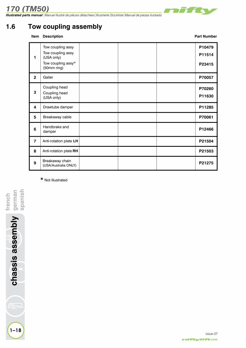
1.6 Tow coupling assemblyItem Description Part Number
1
Tow coupling assy
Tow coupling assy (USA only)
Tow coupling assy*(50mm ring)
P10479
P11514
P23415
2 Gaiter P70057
3Coupling head
Coupling head (USA only)
P70260
P11630
4 Drawtube damper P11285
5 Breakaway cable P70061
6 Handbrake and damper P12466
7 Anti-rotation plate LH P21504
8 Anti-rotation plate RH P21503
9 Breakaway chain(USA/Australia ONLY)
P21275
* Not illustrated

170 (TM50)
fren
chg
erm
ansp
anis
hch
assi
s as
sem
bly
1–19
illustrated parts manualManuel illustré de pièces détachées Illustrierte Stückliste Manual de piezas ilustrado
issue 07Figure 1.6 Tow coupling assembly
1
2
3
4
56
7 8
Sec
urin
g b
olt
(see
No
te)
9

170 (TM50)
1–20
chas
sis
asse
mb
lyfr
ench
ger
man
span
ish
illustrated parts manual Manuel illustré de pièces détachées Illustrierte Stückliste Manual de piezas ilustrado
issue 07
1.7 Heavy duty jockey wheelItem Description Part Number
1 *Jockey wheel A) assembly B)
P14065P25035
2 *Jockey wheel A) assembly B)(traction drive)
P13898P25036
3 *Gear kit A)
B)P15183P25037
4 Knob P70076
5 *Plastic Cap A)
B)P16480P25040
6 Wheel P16309
7 *Inner shaft A)
B)P14066P25038
8 *Inner shaft A)(Twin wheel) B)
P16308P25039
9 Bearing - Inner P11675
* A) Cap size (Item 5) is 90mm squareB) Cap size (Item 5) is 70mm square

170 (TM50)
fren
chg
erm
ansp
anis
hch
assi
s as
sem
bly
1–21
illustrated parts manualManuel illustré de pièces détachées Illustrierte Stückliste Manual de piezas ilustrado
issue 07Figure 1.7 Heavy duty jockey wheel
3
7
5
8
6
6
4
1
2
9

170 (TM50)
1–22
chas
sis
asse
mb
lyfr
ench
ger
man
span
ish
illustrated parts manual Manuel illustré de pièces détachées Illustrierte Stückliste Manual de piezas ilustrado
issue 07
1.8 Lighting assembliesItem Description Part Number
1Lighting board - UK
EuropeanGerman TUV
P10313P10754P11200
2 Fog light lens P10898
3 Fog light assembly P70197
4 Lamp assembly P70196
5 Tail light bulb P70202
6 Indicator bulb P70201
7 Warning triangle P70198
8Plug/Lead UK/Euro
USAAustralia
P70200P11761P25977
9 Mounting bracket P17962
10Light assembly
LHRH
P17602P17601
11Bracket - Light cluster & number plate RH P17963
12 Light assembly P20906
13 Side lens ONLY P21146
14 Rear lens ONLY P20907
15 Lighting Board(Includes Item 16) P23996
16Lamp assembly LH
*RHP24236P24237
* Not illustrated

170 (TM50)
fren
chg
erm
ansp
anis
hch
assi
s as
sem
bly
1–23
illustrated parts manualManuel illustré de pièces détachées Illustrierte Stückliste Manual de piezas ilustrado
issue 07Figure 1.8 Lighting assemblies
1
1014
23
4
167
5
8
6
911
10
9 12 13 US
A O
NLY
Aus
tral
ia O
NLY
15

170 (TM50)
1–24
chas
sis
asse
mb
lyfr
ench
ger
man
span
ish
illustrated parts manual Manuel illustré de pièces détachées Illustrierte Stückliste Manual de piezas ilustrado
issue 07
1.9 Wheel hub assemblyItem Description Part Number
1Grease cap Steel
PlasticP15493P15492
2 Hub nut P15452
3 Hub washer P15496
4 Outer bearing P15489
5Wheel boltWheel stud
P13689P13931
6 Hub P15494
7 Oil seal P15498
8 Inner bearing P15487
9 Half shell P70263
10 Adjuster wedge P15428
11 Adjuster post P15431
12 Brake shoe (Pair) P70025
13 Spring P15439
14 Steady spring P15417
15 Expander P70032
16 Spring P15442
17 Spring P15435

170 (TM50)
fren
chg
erm
ansp
anis
hch
assi
s as
sem
bly
1–25
illustrated parts manualManuel illustré de pièces détachées Illustrierte Stückliste Manual de piezas ilustrado
issue 07Figure 1.9 Wheel hub assembly
�
�
�
��
��
��
����
��
�
�� ��
��
� �

170 (TM50)
1–26
chas
sis
asse
mb
lyfr
ench
ger
man
span
ish
illustrated parts manual Manuel illustré de pièces détachées Illustrierte Stückliste Manual de piezas ilustrado
issue 07
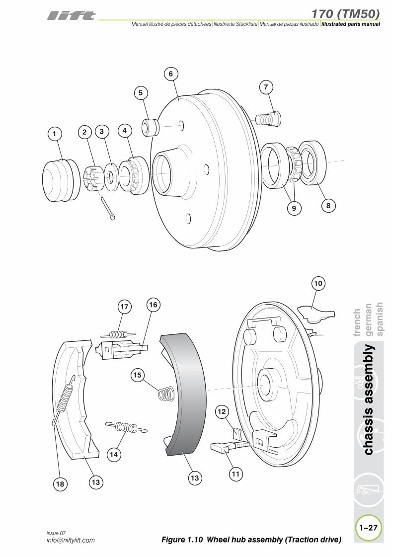
1.10 Wheel hub assembly (Traction drive)Item Description Part Number
1 Grease cap P15493
2 Hub nut P15491
3 Hub washer P15497
4 Outer bearing P15490
5 Wheel nut P70258
6 Hub P15495
7 Wheel stud P70259
8 Oil seal P15499
9 Inner bearing P15488
10 Half shell P15420
11 Adjuster wedge P15429
12 Adjuster post P15418
13 Brake shoe (Pair) P12412
14 Spring P15440
15 Steady spring P15433
16 Expander P15419
17 Spring P15443
18 Spring P15436
170 (TM50)
fren
chg
erm
ansp
anis
hch
assi
s as
sem
bly
1–27
illustrated parts manualManuel illustré de pièces détachées Illustrierte Stückliste Manual de piezas ilustrado
issue 07Figure 1.10 Wheel hub assembly (Traction drive)
�
�
�
�
��
��
��
����
�
�
��
�� ��
��
� �

170 (TM50)
1–28
chas
sis
asse
mb
lyfr
ench
ger
man
span
ish
illustrated parts manual Manuel illustré de pièces détachées Illustrierte Stückliste Manual de piezas ilustrado
issue 07
1.11 Valve block (Traction drive)Item Description Part Number
1 Joystick P16125
2 Button - Red P17994
3 Rubber gaiter P17921
4 Valve - Cartridge P19121
5 Bracket - Valveblock P16048
6 Valve block P14395
7 * Seal kit for item 6 P18156
8 Gaiter - Lever cap P19119
9 Lever cap P19120
10 Lever P16306
* Not illustrated

170 (TM50)
fren
chg
erm
ansp
anis
hch
assi
s as
sem
bly
1–29
illustrated parts manualManuel illustré de pièces détachées Illustrierte Stückliste Manual de piezas ilustrado
issue 07Figure 1.11 Valve block assembly
4
1
5
3
6
2
7*
10
98

170 (TM50)
1–30
chas
sis
asse
mb
lyfr
ench
ger
man
span
ish
illustrated parts manual Manuel illustré de pièces détachées Illustrierte Stückliste Manual de piezas ilustrado
issue 07
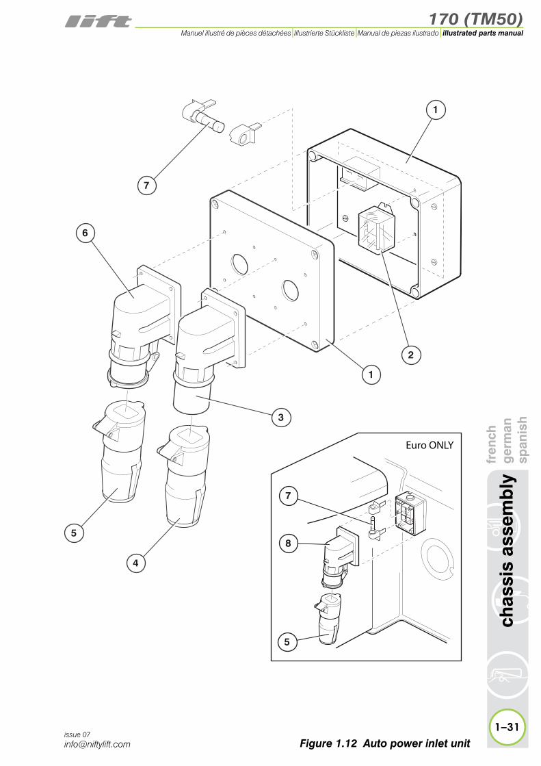
1.12 auto power inlet unit (UK)Item Description Part Number
Complete assembly P20415
1 ABS box P20815
2 Relay P20767
3 Inlet - 110v P23869
4 Plug - 110v P10724
5 Plug - 240v P10268
6 Inlet - 240v P23870
7 Fuse - 20A P20897
8 Inlet - 240v P10174
170 (TM50)
fren
chg
erm
ansp
anis
hch
assi
s as
sem
bly
1–31
illustrated parts manualManuel illustré de pièces détachées Illustrierte Stückliste Manual de piezas ilustrado
issue 07
3
1
1
2
7
5
4
6
7
8
5
Euro ONLY
Figure 1.12 Auto power inlet unit


170 (TM50)
2
illustrated parts manualManuel illustré de pièces détachéesIllustrierte StücklisteManual de piezas ilustrado
superstructurefrench
germanspanish

170 (TM50)illustrated parts manual Manuel illustré de pièces détachées Illustrierte Stückliste Manual de piezas ilustrado
sup
erst
ruct
ure
fren
chg
erm
ansp
anis
h2.1 Power tray (Petrol/Diesel/Bi-energy)
Item Description Part Number
1 Battery - 12 v P11975
2 Clamp - Battery P12295
3 Regulator(Bi-energy ONLY) P13637
4 Handle - Hand pump P10624
5PCB Control boxSee “Control box” on page 2-16.
N/A
6 Siren P11113
7Solenoid valve assyCoil ONLY
P10132P70354
8 Valve - non-return P10107
9Fuse - 125 A
Fuse holder
P12696
P11976
10 Canopy P10755
11 Handle P10241
12 Knob P10186
13
Power packSee “DC Power pack” on page 2-22.or“DC Power pack (Traction Drive)” on page 2-24.
P22476
P16211
14 Hydraulic oil filter & bowl assembly P10137
15 Oil filter cartridge P10766
16 Flow switch(Bi-energy ONLY) P13842
17 Bracket - PCB Box P12617
18 Gear wheel P10490
19Worm assemblySee “Slew assembly” on page 2-8.
N/A
20 Battery - 6 v P10829
21Battery clamp Flat
AngledP12671P10907
22 Battery Charger P19205
2–2issue 08

170 (TM50)
fren
chg
erm
ansp
anis
hsu
per
stru
ctur
e
2–3
illustrated parts manualManuel illustré de pièces détachées Illustrierte Stückliste Manual de piezas ilustrado
issue 08
1011
12
23
14
16
15
13
18 1920
39
2225
28
2627*
24
23
3233
1
3031
17
21
34
3635
37
78
4 56
9
29
3839
Figure 2.1 Power tray (PDE)

170 (TM50)illustrated parts manual Manuel illustré de pièces détachées Illustrierte Stückliste Manual de piezas ilustrado
2–4
sup
erst
ruct
ure
fren
chg
erm
ansp
anis
h2.1 continued
Item Description Part Number
23 Battery Charger P19205
24Fuse - 225 A
Fuse holder
P11977
P11976
25Anderson connectorsSee “Anderson con-nector” on page 2-30.
N/A
26 Tilt sensor (OPTIONAL) P16108
27 Manual hand pump P22570
28 * Seal kit for item 27 P22605
29 Switch (Diesel ONLY) P12763
30Diverter valveLever ONLY
P10702P14397
31
Control valve3 spool
See “Control valve assembly (3 spool)”
on page 2-10.4 spool
see “Control valve assembly (4 spool)”
on page 2-12.
P15514
P15518
32
Button boxSee “Button box assemblies (Base)” on page 2-14.
N/A
33 Engine mount P11012
34 Mounting plate P11236
35
Petrol engineGX160GX200
Diesel engineSee “Diesel engine (Kubota OC60)” on
page 2-28.
P18916P16389P10296
36Coupling - Petrol
DieselP12287P11500
37Bell housing - Petrol
DieselP12286P11499
38 Pump - 2.5 cc P11467
39 Handle - Anderson P16942
40 Anderson connector12v P17085
issue 08* Not illustrated

170 (TM50)
fren
chg
erm
ansp
anis
hsu
per
stru
ctur
e
2–5
illustrated parts manualManuel illustré de pièces détachées Illustrierte Stückliste Manual de piezas ilustrado
issue 08
1011
12
23
15
14
16
13
19 2021
40
2326
29
2728*
25
24
3334
1
3132
18
2217
35
3736
38
78
4 56
9
30
3940
Figure 2.1 Power tray (PDE)

170 (TM50)illustrated parts manual Manuel illustré de pièces détachées Illustrierte Stückliste Manual de piezas ilustrado
2–6
sup
erst
ruct
ure
fren
chg
erm
ansp
anis
h2.2 Power tray (AC/Mains)
Item Description Part Number
1 Handle - Hand pump P10624
2 Solenoid valve assy P10132
3 Coil only(Solenoid valve) P70354
4 Valve - non-return P10107
5Power pack (AC)See “AC Power pack” on page 2-26.
P22669
6 Canopy P10755
7 Handle P10241
8 Knob P10186
9 AC booster box P11982
10 Gear wheel P10490
11Worm assemblySee “Slew assembly” on page 2-8.
N/A
12AC transformer boxSee “AC transformer box” on page 2-20.
N/A
13 Siren P11113
14 Tilt sensor (OPTIONAL) P16108
15 Hand pump P22570
16 * Seal kit for item 15 P22605
17Diverter valveLever ONLY
P10702P14397
18
Control valve3 spool
See “Control valve assembly (3 spool)”
on page 2-10.4 spool
or “Control valve assembly (4 spool)”
on page 2-12.
P15514
P15518
19
Button boxSee “Button box assemblies (Base)” on page 2-14.
N/A
20 Handle - Anderson P16942
issue 08* Not illustrated

170 (TM50)
fren
chg
erm
ansp
anis
hsu
per
stru
ctur
e
2–7
illustrated parts manualManuel illustré de pièces détachées Illustrierte Stückliste Manual de piezas ilustrado
issue 08
6
17
1819
11
1
12
14
13
32
21
5
4
16*
15
78
9 10
2021
21 Anderson connector12v P17085
Figure 2.2 Power tray (AC/Mains)

170 (TM50)illustrated parts manual Manuel illustré de pièces détachées Illustrierte Stückliste Manual de piezas ilustrado
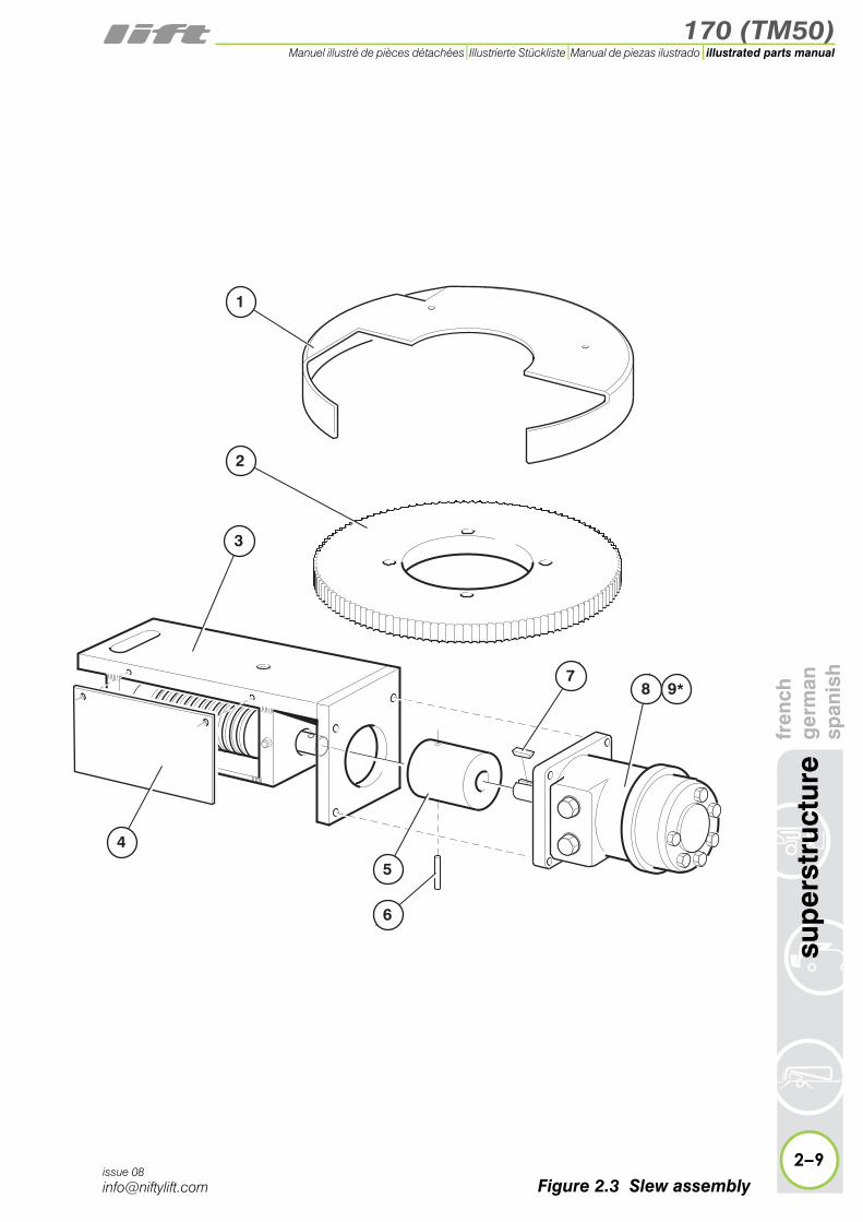
2.3 Slew assemblyItem Description Part Number
1 Guard P10795
2 Gear wheel P10490
3 Worm assembly P10038
4 Cover plate P16307
5 Coupling P10042
6 Roll pin P70112
7 Drive shaft key P14378
8 Motor P14305
9 * Seal kit for item 8 P14377
2–8
sup
erst
ruct
ure
fren
chg
erm
ansp
anis
h
issue 08
* Not illustrated
170 (TM50)
fren
chg
erm
ansp
anis
hsu
per
stru
ctur
e
2–9
illustrated parts manualManuel illustré de pièces détachées Illustrierte Stückliste Manual de piezas ilustrado
issue 08
3
1
2
6
5
4
87
9*
Figure 2.3 Slew assembly

170 (TM50)illustrated parts manual Manuel illustré de pièces détachées Illustrierte Stückliste Manual de piezas ilustrado
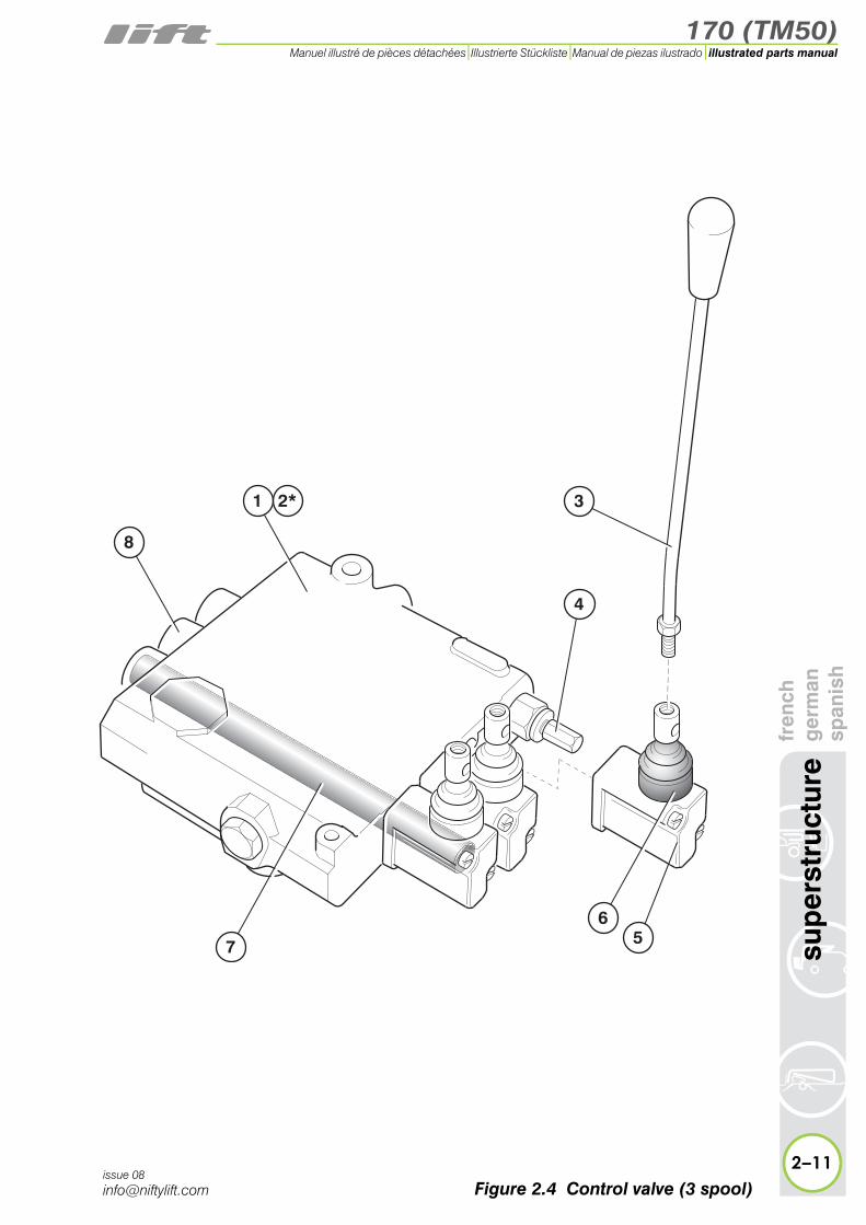
2.4 Control valve assembly (3 spool)Item Description Part Number
1Control valve AS
ASTP15514P15515
2 * Seal kit for item 1 P70337
3 Lever P70336
4 Pressure relief valve P70335
5 Lever cap(complete) P70338
6 Rubber boot P12225
7Spool AS
ASTP15510P15511
8 Spool return spring assembly P16234
2–10
sup
erst
ruct
ure
fren
chg
erm
ansp
anis
h
issue 08
* Not illustrated
170 (TM50)
fren
chg
erm
ansp
anis
hsu
per
stru
ctur
e
2–11
illustrated parts manualManuel illustré de pièces détachées Illustrierte Stückliste Manual de piezas ilustrado
issue 08
1 3
56
7
4
2*
8
Figure 2.4 Control valve (3 spool)
170 (TM50)illustrated parts manual Manuel illustré de pièces détachées Illustrierte Stückliste Manual de piezas ilustrado
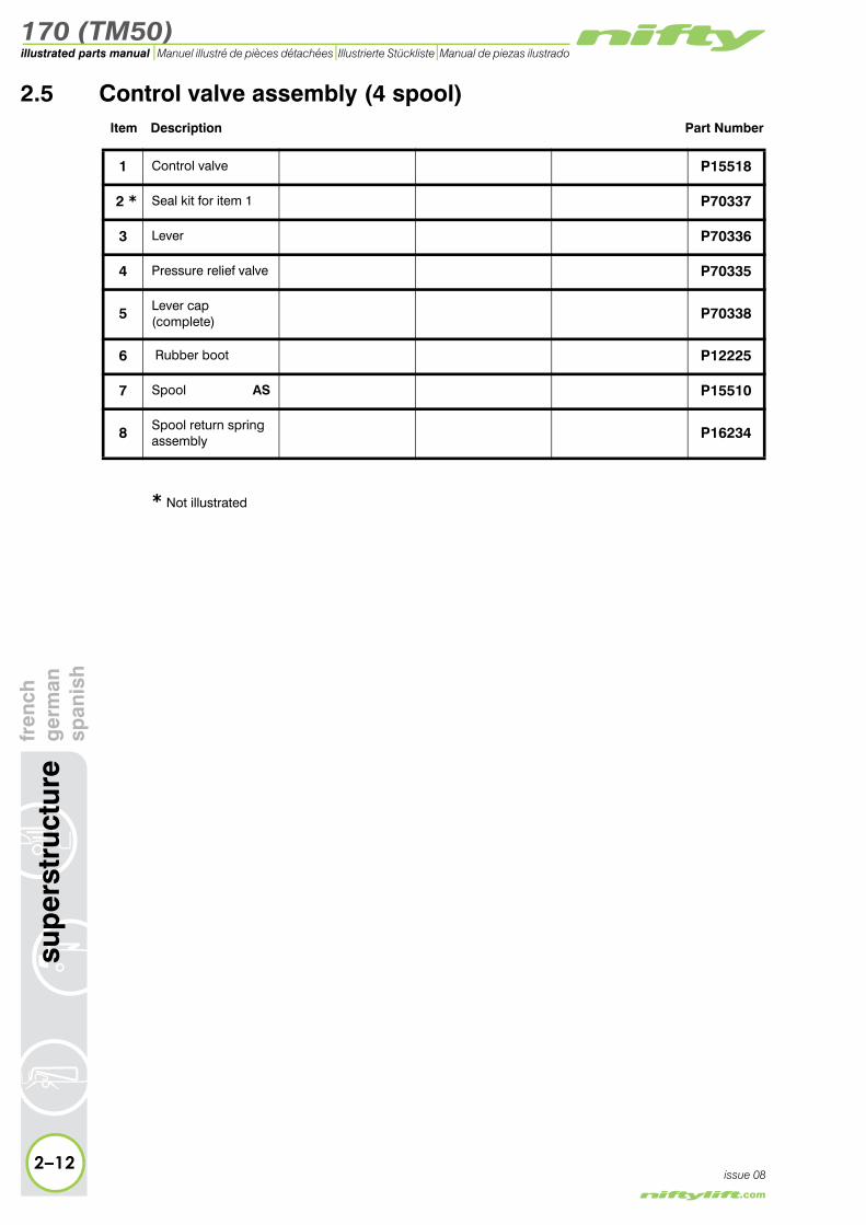
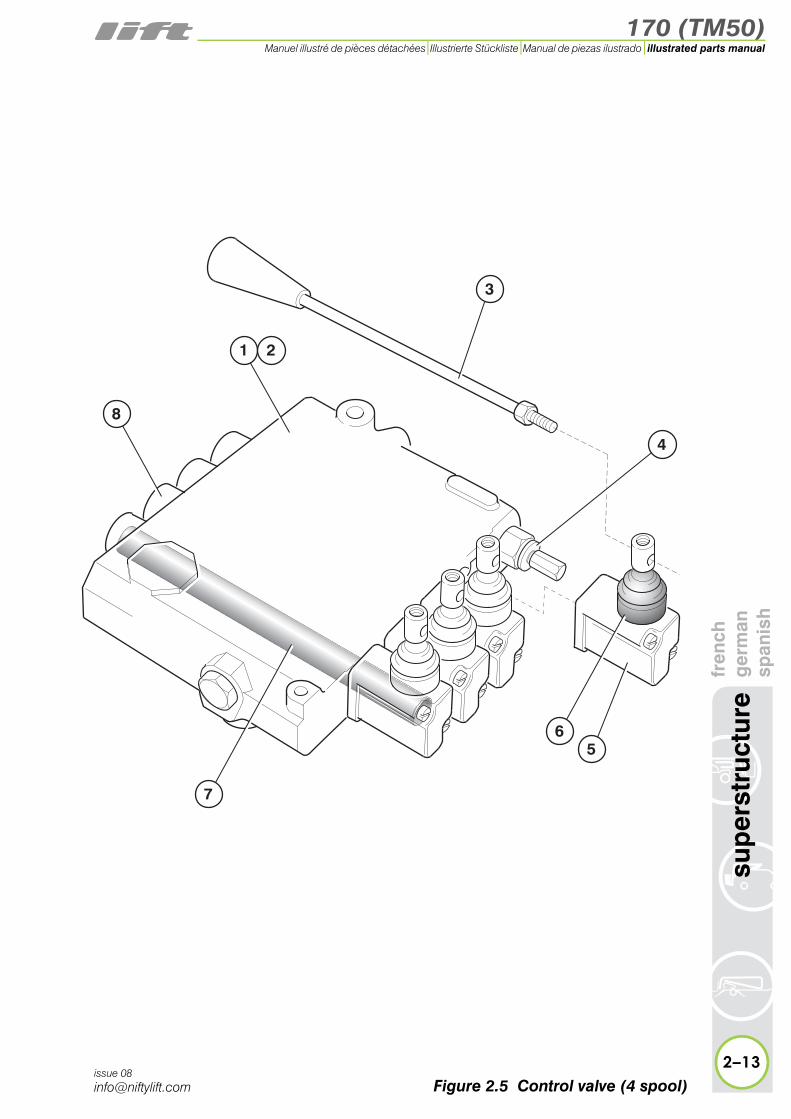
2.5 Control valve assembly (4 spool)Item Description Part Number
1 Control valve P15518
2 * Seal kit for item 1 P70337
3 Lever P70336
4 Pressure relief valve P70335
5 Lever cap(complete) P70338
6 Rubber boot P12225
7 Spool AS P15510
8 Spool return spring assembly P16234
2–12
sup
erst
ruct
ure
fren
chg
erm
ansp
anis
h
issue 08
* Not illustrated
170 (TM50)
fren
chg
erm
ansp
anis
hsu
per
stru
ctur
e
2–13
illustrated parts manualManuel illustré de pièces détachées Illustrierte Stückliste Manual de piezas ilustrado
issue 08
1
3
56
7
4
2
8
Figure 2.5 Control valve (4 spool)
170 (TM50)illustrated parts manual Manuel illustré de pièces détachées Illustrierte Stückliste Manual de piezas ilustrado
2–14
sup
erst
ruct
ure
fren
chg
erm
ansp
anis
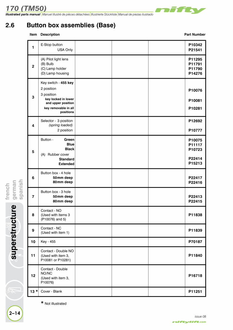
h2.6 Button box assemblies (Base)
Item Description Part Number
1E-Stop button
USA OnlyP10342P21541
2
(A) Pilot light lens(B) Bulb(C) Lamp holder(D) Lamp housing
P11295P11791P11790P14276
3
Key switch - 455 key
2 position
3 positionkey locked in lowerand upper position
key removable in all positions
P10076
P10081
P10281
4Selector - 3 position
(spring loaded)2 position
P12692
P10777
5
Button - GreenBlue
Black
(A) Rubber coverStandardExtended
P10075P11117P10723
P22414P15213
6Button box - 4 hole
50 mm deep80 mm deep
P22417P22416
7Button box - 3 hole
50 mm deep80 mm deep
P22413P22415
8Contact - NO(Used with items 3 (P10076) and 5)
P11838
9 Contact - NC(Used with item 1) P11839
10 Key - 455 P70187
11Contact - Double NO(Used with item 3, P10081 or P10281)
P11840
12
Contact - Double NO/NC(Used with item 3, P10076)
P16718
13 * Cover - Blank P11251
* Not illustrated
issue 08

170 (TM50)
fren
chg
erm
ansp
anis
hsu
per
stru
ctur
e
2–15
illustrated parts manualManuel illustré de pièces détachées Illustrierte Stückliste Manual de piezas ilustrado
issue 08
A
A
B
C
D
7
6
1
5
3
1
2
5
3
12111098
1
3
4
5
2
Figure 2.6 Button boxes (Base)
170 (TM50)illustrated parts manual Manuel illustré de pièces détachées Illustrierte Stückliste Manual de piezas ilustrado
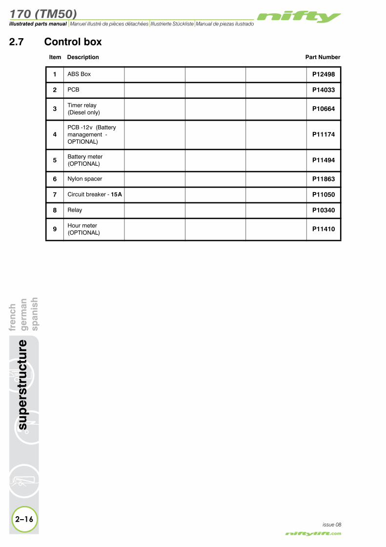
2.7 Control boxItem Description Part Number
1 ABS Box P12498
2 PCB P14033
3 Timer relay(Diesel only) P10664
4PCB -12 v (Battery management - OPTIONAL)
P11174
5 Battery meter(OPTIONAL) P11494
6 Nylon spacer P11863
7 Circuit breaker - 15 A P11050
8 Relay P10340
9 Hour meter(OPTIONAL) P11410
2–16
sup
erst
ruct
ure
fren
chg
erm
ansp
anis
h
issue 08

170 (TM50)
fren
chg
erm
ansp
anis
hsu
per
stru
ctur
e
2–17
illustrated parts manualManuel illustré de pièces détachées Illustrierte Stückliste Manual de piezas ilustrado
issue 08
�
�
� �
�
��
�
Figure 2.7 Control box

170 (TM50)illustrated parts manual Manuel illustré de pièces détachées Illustrierte Stückliste Manual de piezas ilustrado
2.8 Diesel boxItem Description Part Number
Complete assembly P13627
1 ABS Box P12861
2 Capacitor P12992
3 Circuit breaker - 10 A P11719
4 Timer relay P10664
5 Relay - 12 v P10340
6 Hour meter (OPTIONAL) P11410
2–18
sup
erst
ruct
ure
fren
chg
erm
ansp
anis
h
issue 08

170 (TM50)
fren
chg
erm
ansp
anis
hsu
per
stru
ctur
e
2–19
illustrated parts manualManuel illustré de pièces détachées Illustrierte Stückliste Manual de piezas ilustrado
issue 08
�
�
�
�
�
�
Figure 2.8 Diesel box

170 (TM50)illustrated parts manual Manuel illustré de pièces détachées Illustrierte Stückliste Manual de piezas ilustrado
2.9 AC transformer boxItem Description Part Number
1Complete assembly
240 v
110 v
P10770
P11429
2Fuse 16 A (240 v)
25 A (110 v)P11767P14040
3 Fuse 3.15 A P15504
4Circuit board assy.
240 v
110 v
P10847P14039
5 Hour meter (OPTIONAL) P11410
6 Siren P11113
2–20
sup
erst
ruct
ure
fren
chg
erm
ansp
anis
h
issue 08

170 (TM50)
fren
chg
erm
ansp
anis
hsu
per
stru
ctur
e
2–21
illustrated parts manualManuel illustré de pièces détachées Illustrierte Stückliste Manual de piezas ilustrado
issue 08
�
�
�
�
�
�
Figure 2.9 AC Transformer box

170 (TM50)illustrated parts manual Manuel illustré de pièces détachées Illustrierte Stückliste Manual de piezas ilustrado
ture
fren
chg
erm
ansp
anis
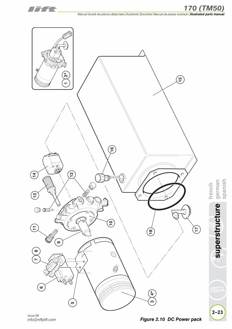
h2.10 DC Power pack
Item Description Part Number
1 Power pack complete P22476
2 * Seal kit for item 1 P70171
3 Motor P11217
4 * Brushes for item 3 P11226
5 Contactor plate P16315
6Contact solenoid -
12 v (Bi-energy) P11877
7 Fuse - 225 A P11977
8 Fuse holder P11976
9 Coupling P24949
10 Centre plate P22879
11 Relief valve kit P70158
12 Check valve/Filter kit P70159
13 Filter - Return line P70247
14 Pump - 1.5 cc P22881
15 Tank - 15 litre P11007
16 Filler cap P70166
17 Filter - suction P70155
18 O-ring P15303
2–22
sup
erst
ruc
issue 08
* Not illustrated
170 (TM50)
fren
chg
erm
ansp
anis
hsu
per
stru
ctur
e
2–23
illustrated parts manualManuel illustré de pièces détachées Illustrierte Stückliste Manual de piezas ilustrado
issue 08
15
1113
14
17
9
10
5
16
121
2*
34*
6
18
78
Figure 2.10 DC Power pack

170 (TM50)illustrated parts manual Manuel illustré de pièces détachées Illustrierte Stückliste Manual de piezas ilustrado
fren
chg
erm
ansp
anis
h2.11 DC Power pack (Traction Drive)
Item Description Part Number
1 Power pack complete P16211
2 Motor P16611
3 * Brush & Spring Set for item 2 P21151
4 Contactor plate P16315
5 Contact solenoid P11877
6 Fuse - 300 A P12407
7 Fuse holder P11976
8 Flange - Motor P18153
9 Fan blade assy P22610
10 Check valve kit P16614
11 Flange P16612
12 O-ring P16616
13 Filter - Return line P16734
14 Pump - 2.2 cc P16699
15 Filter - suction P16700
16 Tank - 25 litre P16314
17 Filler cap P17259
2–24
sup
erst
ruct
ure
issue 08
18 Coupling P20063
19 Relief valve kit P16613
20 Cap P16615
* Not illustrated

170 (TM50)
fren
chg
erm
ansp
anis
hsu
per
stru
ctur
e
2–25
illustrated parts manualManuel illustré de pièces détachées Illustrierte Stückliste Manual de piezas ilustrado
issue 08
16
1314
1511
98
1210
19
20
1718
1
23*
5 4
67
Figure 2.11 DC Power pack (Traction drive)
170 (TM50)illustrated parts manual Manuel illustré de pièces détachées Illustrierte Stückliste Manual de piezas ilustrado
nch
rman
anis
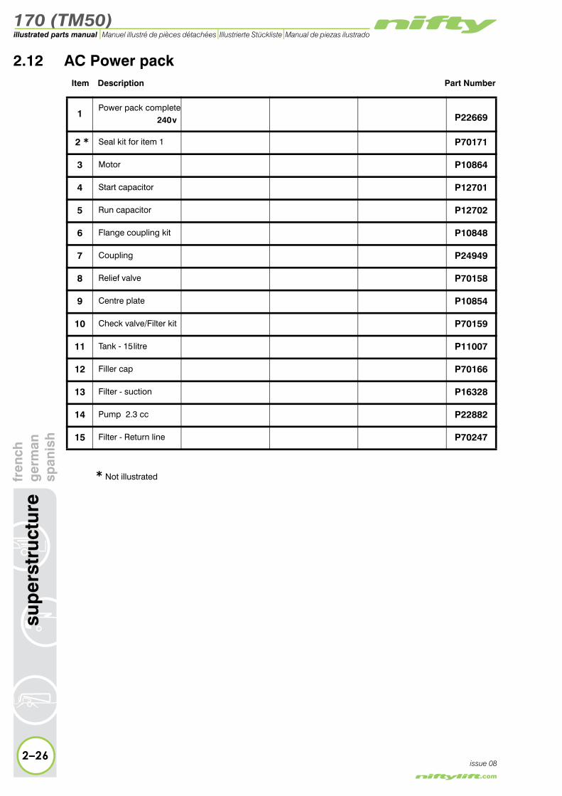
h2.12 AC Power pack
Item Description Part Number
1Power pack complete
240 v P22669
2 * Seal kit for item 1 P70171
3 Motor P10864
4 Start capacitor P12701
5 Run capacitor P12702
6 Flange coupling kit P10848
7 Coupling P24949
8 Relief valve P70158
9 Centre plate P10854
10 Check valve/Filter kit P70159
11 Tank - 15 litre P11007
12 Filler cap P70166
13 Filter - suction P16328
14 Pump 2.3 cc P22882
15 Filter - Return line P70247
2–26
sup
erst
ruct
ure
fre
ge
sp
issue 08
* Not illustrated

170 (TM50)
fren
chg
erm
ansp
anis
hsu
per
stru
ctur
e
2–27
illustrated parts manualManuel illustré de pièces détachées Illustrierte Stückliste Manual de piezas ilustrado
issue 08
11
13
9
12
315
14
10
5 4
6
7
8
12*
Figure 2.12 AC Power pack

170 (TM50)illustrated parts manual Manuel illustré de pièces détachées Illustrierte Stückliste Manual de piezas ilustrado
ch man
nish
2.13 Diesel engine (Kubota OC60)Item Description Part Number
1 Muffler assembly P13687
2 Exhaust P11644
3 Air filter P11647
4 Starter motor P11981
5 Rubber engine mounting P11012
6 Stop solenoid P70271
7 Oil filter P13335
8 Regulator P12640
9 Fuel filter P13336
10 Fuel tank assembly P15415
11 Gauze fuel filter P13284
12 Filler cap P15505
13 Starter key (Pair) P11646
14 Starter switch assy P12763
15 Fuse - 30 A P14197
2–28
sup
erst
ruct
ure
fren
ger
spa
issue 08

170 (TM50)
fren
chg
erm
ansp
anis
hsu
per
stru
ctur
e
2–29
illustrated parts manualManuel illustré de pièces détachées Illustrierte Stückliste Manual de piezas ilustrado
issue 08
�
�
�
�
��
�
�
�
��
��
��
��
��
Figure 2.13 Diesel engine (Kubota OC60)

170 (TM50)illustrated parts manual Manuel illustré de pièces détachées Illustrierte Stückliste Manual de piezas ilustrado
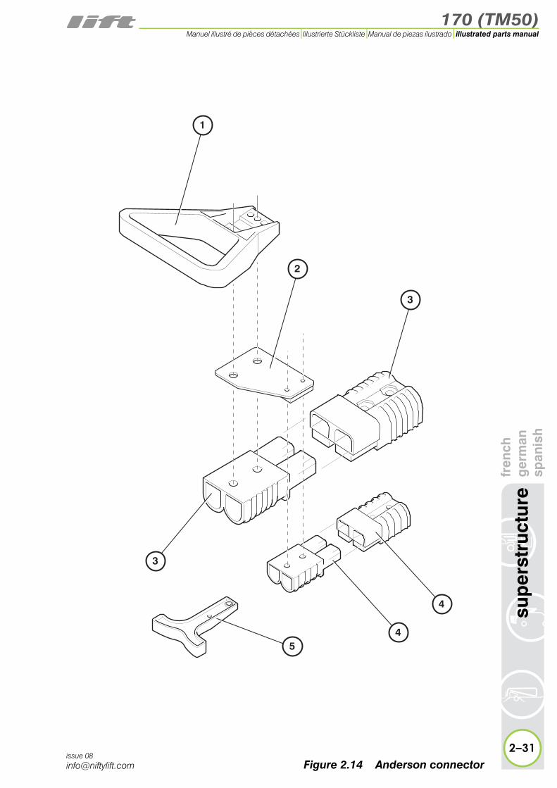
2.14 Anderson connectorItem Description Part Number
1 Handle P17084
2 Mounting plate P15271
3 Connector - 24 v P17083
4 Connector - 12 v P17085
5 Handle - Anderson P16942
2–30
sup
erst
ruct
ure
fren
chg
erm
ansp
anis
h
issue 08
170 (TM50)
fren
chg
erm
ansp
anis
hsu
per
stru
ctur
e
2–31
illustrated parts manualManuel illustré de pièces détachées Illustrierte Stückliste Manual de piezas ilustrado
issue 08
1
2
3
5
3
4
4
Figure 2.14 Anderson connector


170 (TM50)
3
illustrated parts manualManuel illustré de pièces détachéesIllustrierte StücklisteManual de piezas ilustrado
boom assembliesfrench
germanspanish
170 (TM50)illustrated parts manual Manuel illustré de pièces détachées Illustrierte Stückliste Manual de piezas ilustrado
bo
om
ass
emb
lies
fren
chg
erm
ansp
anis
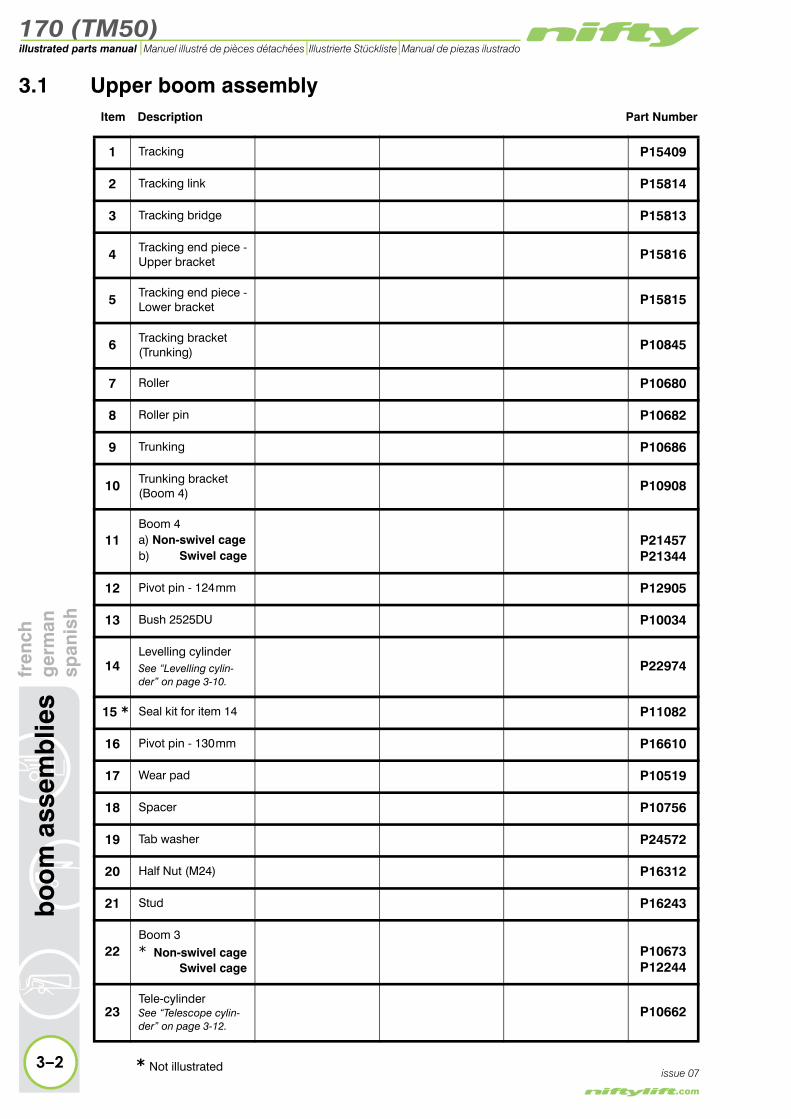
h3.1 Upper boom assembly
Item Description Part Number
1 Tracking P15409
2 Tracking link P15814
3 Tracking bridge P15813
4 Tracking end piece -Upper bracket P15816
5 Tracking end piece -Lower bracket P15815
6 Tracking bracket(Trunking) P10845
7 Roller P10680
8 Roller pin P10682
9 Trunking P10686
10 Trunking bracket(Boom 4) P10908
11Boom 4a) Non-swivel cageb) Swivel cage
P21457P21344
12 Pivot pin - 124 mm P12905
13 Bush 2525DU P10034
14Levelling cylinderSee “Levelling cylin-der” on page 3-10.
P22974
15 * Seal kit for item 14 P11082
16 Pivot pin - 130 mm P16610
17 Wear pad P10519
18 Spacer P10756
19 Tab washer P24572
20 Half Nut (M24) P16312
21 Stud P16243
22Boom 3* Non-swivel cage
Swivel cageP10673P12244
23Tele-cylinderSee “Telescope cylin-der” on page 3-12.
P10662
3–2issue 07* Not illustrated

170 (TM50)
fren
chg
erm
ansp
anis
hb
oo
m a
ssem
blie
s
3–3
illustrated parts manualManuel illustré de pièces détachées Illustrierte Stückliste Manual de piezas ilustrado
issue 07
9
30
16
11b
13
26
10
4
23
29
36
34
32
22
16
12
21
20
7
39
3837
6321
35
17
18
19
31
5
24
27
28
8
33*
25*
1514*
40
46
42
43
41
44
45
47 11a
Figure 3.1 Upper boom assembly

170 (TM50)illustrated parts manual Manuel illustré de pièces détachées Illustrierte Stückliste Manual de piezas ilustrado
bo
om
ass
emb
lies
fren
chg
erm
ansp
anis
h3.1 continued
Item Description Part Number
24
Lift cylinderNon-swivel cage
Swivel cageSee “Lift cylinder” on page 3-8.
P10894P17711
25 * Seal kit for item 24 P12870
26Knuckle* Non-swivel cage
Swivel cageP10852P11894
27 Pivot pin - 146 mm P10873
28 Pivot pin - 325 mm P10496
29 Pivot pin - 102 mm P10498
30Pivot pin
Non-swivel (102mm)
Swivel (91 mm)P11269P12048
31 Spacer P11110
32 Bush 3040DU P10508
33Levelling cylinderSee “Levelling cylin-der” on page 3-10.
P11764
34 * Seal kit for item 33 P11082
35Pivot pin
Non-swivel (68mm)
Swivel ( 78 mm)P12900P12718
36 Stud P11436
37 Keeper plate P10711
38 Shim P13296
39 Wear pad P10735
40 Rubber latch P18554
41 Insulator P11607
42 Rubber boom rest P11010
43 Spring P13372
44 Guard - Boom rest P10980
45 Microswitch P18937
46 Block P13309
47 Bracket - Cage stop P23069
3–4issue 07* Not illustrated

170 (TM50)
fren
chg
erm
ansp
anis
hb
oo
m a
ssem
blie
s
3–5
illustrated parts manualManuel illustré de pièces détachées Illustrierte Stückliste Manual de piezas ilustrado
issue 07Figure 3.1 Upper boom assembly
9
30
16
11b
13
26
10
4
23
29
36
34
32
22
16
12
21
20
7
39
3837
6321
35
17
18
19
31
5
24
27
28
8
33*
25*
1514*
40
46
42
43
41
44
45
47 11a
170 (TM50)illustrated parts manual Manuel illustré de pièces détachées Illustrierte Stückliste Manual de piezas ilustrado
bo
om
ass
emb
lies
fren
chg
erm
ansp
anis
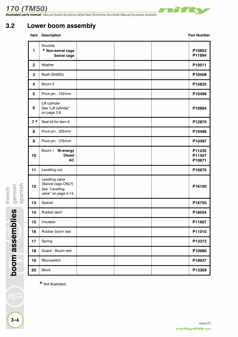
h3.2 Lower boom assembly
Item Description Part Number
1Knuckle* Non-swivel cage
Swivel cageP10852P11894
2 Washer P10511
3 Bush 3040DU P10508
4 Boom 2 P15835
5 Pivot pin - 102 mm P10498
6Lift cylinderSee “Lift cylinder” on page 3-8.
P10894
7 * Seal kit for item 6 P12870
8 Pivot pin - 325 mm P10496
9 Pivot pin - 376 mm P10497
10Boom 1 Bi-energy
DieselAC
P11235P11457P10671
11 Levelling rod P10675
12
Levelling valve(Swivel cage ONLY)See “Levelling valve” on page 3-14.
P16100
13 Spacer P16750
14 Rubber latch P18554
15 Insulator P11607
16 Rubber boom rest P11010
17 Spring P13372
18 Guard - Boom rest P10980
19 Microswitch P18937
20 Block P13309
3–6issue 07
* Not illustrated

170 (TM50)
fren
chg
erm
ansp
anis
hb
oo
m a
ssem
blie
s
3–7
illustrated parts manualManuel illustré de pièces détachées Illustrierte Stückliste Manual de piezas ilustrado
issue 07
4
5
3
3
2
2
10
6
2
3
8
11
9
8
8
11
2
1213
3 3
1
2
2
7*
14
20
16
17
15
18
19
Figure 3.2 Lower boom assembly
170 (TM50)illustrated parts manual Manuel illustré de pièces détachées Illustrierte Stückliste Manual de piezas ilustrado
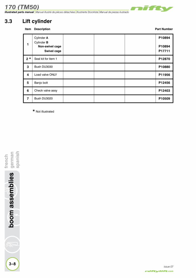
3.3 Lift cylinderItem Description Part Number
1
Cylinder A
Cylinder BNon-swivel cage
Swivel cage
P10894
P10894P17711
2 * Seal kit for item 1 P12870
3 Bush DU3030 P10880
4 Load valve ONLY P11956
5 Banjo bolt P12456
6 Check valve assy P12403
7 Bush DU3020 P10509
3–8
bo
om
ass
emb
lies
fren
chg
erm
ansp
anis
h
issue 07
* Not illustrated

170 (TM50)
fren
chg
erm
ansp
anis
hb
oo
m a
ssem
blie
s
3–9
illustrated parts manualManuel illustré de pièces détachées Illustrierte Stückliste Manual de piezas ilustrado
issue 07
1
3
3
7
4
6
5
2*
CYLINDER A
CYLINDER B
Figure 3.3 Lift cylinder

170 (TM50)illustrated parts manual Manuel illustré de pièces détachées Illustrierte Stückliste Manual de piezas ilustrado
3.4 Levelling cylinderItem Description Part Number
1 Cylinder (slave) P22974
2 * Seal kit for items1 and 4 P11082
3 Bush DU2520 P10032
4 Levelling cylinder P11764
5 Load valve P11956
6 Check valvecartridge P17317
3–10
bo
om
ass
emb
lies
fren
chg
erm
ansp
anis
h
issue 07
* Not illustrated

170 (TM50)
fren
chg
erm
ansp
anis
hb
oo
m a
ssem
blie
s
3–11
illustrated parts manualManuel illustré de pièces détachées Illustrierte Stückliste Manual de piezas ilustrado
issue 07
�
�
�
�
��
��
��
��
Figure 3.4 Levelling cylinder
170 (TM50)illustrated parts manual Manuel illustré de pièces détachées Illustrierte Stückliste Manual de piezas ilustrado
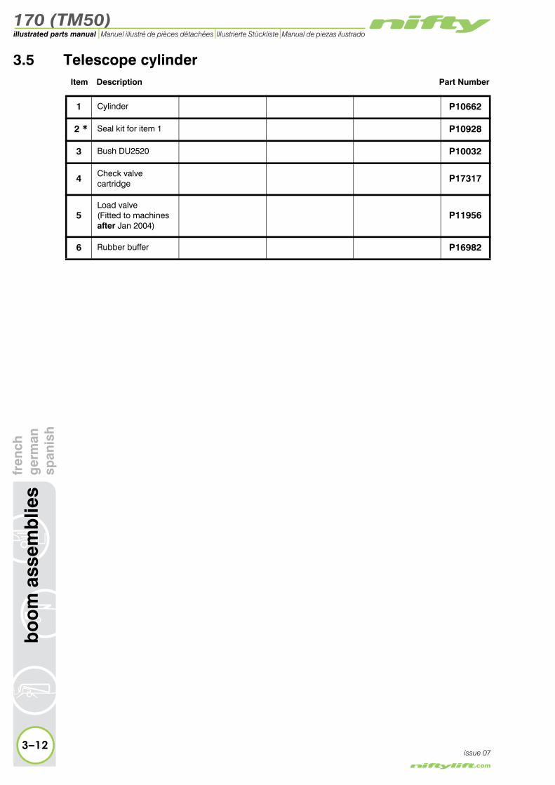
3.5 Telescope cylinderItem Description Part Number
1 Cylinder P10662
2 * Seal kit for item 1 P10928
3 Bush DU2520 P10032
4 Check valvecartridge P17317
5Load valve(Fitted to machinesafter Jan 2004)
P11956
6 Rubber buffer P16982
3–12
bo
om
ass
emb
lies
fren
chg
erm
ansp
anis
h
issue 07

170 (TM50)
fren
chg
erm
ansp
anis
hb
oo
m a
ssem
blie
s
3–13
illustrated parts manualManuel illustré de pièces détachées Illustrierte Stückliste Manual de piezas ilustrado
issue 07
1
54
4
3
2*
6
Figure 3.5 Telescope cylinder
170 (TM50)illustrated parts manual Manuel illustré de pièces détachées Illustrierte Stückliste Manual de piezas ilustrado
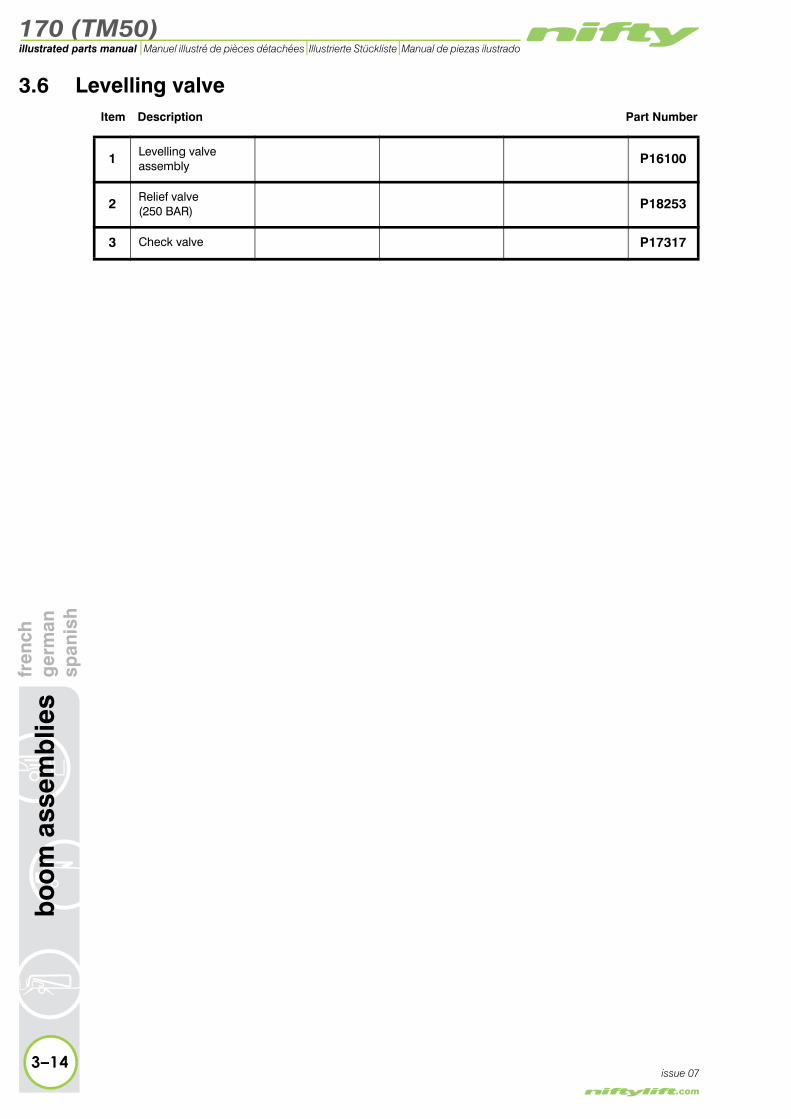
3.6 Levelling valveItem Description Part Number
1 Levelling valve assembly P16100
2 Relief valve(250 BAR) P18253
3 Check valve P17317
3–14
bo
om
ass
emb
lies
fren
chg
erm
ansp
anis
h
issue 07

170 (TM50)
fren
chg
erm
ansp
anis
hb
oo
m a
ssem
blie
s
3–15
illustrated parts manualManuel illustré de pièces détachées Illustrierte Stückliste Manual de piezas ilustrado
issue 07
�
�
�
Figure 3.6 Levelling valve

170 (TM50)
4
illustrated parts manualManuel illustré de pièces détachéesIllustrierte StücklisteManual de piezas ilustrado
cage assemblyfrench
germanspanish
170 (TM50)illustrated parts manual Manuel illustré de pièces détachées Illustrierte Stückliste Manual de piezas ilustrado
4–2
cag
e as
sem
bly
fren
chg
erm
ansp
anis
h
issue 08
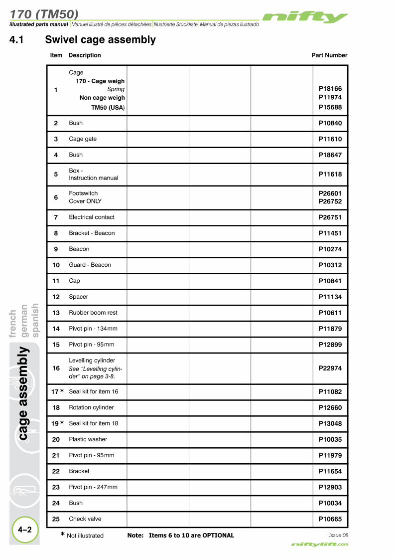
4.1 Swivel cage assemblyItem Description Part Number
1
Cage170 - Cage weigh
SpringNon cage weigh
TM50 (USA)
P18166P11974
P15688
2 Bush P10840
3 Cage gate P11610
4 Bush P18647
5 Box - Instruction manual P11618
6FootswitchCover ONLY
P26601P26752
7 Electrical contact P26751
8 Bracket - Beacon P11451
9 Beacon P10274
10 Guard - Beacon P10312
11 Cap P10841
12 Spacer P11134
13 Rubber boom rest P10611
14 Pivot pin - 134 mm P11879
15 Pivot pin - 95 mm P12899
16Levelling cylinderSee “Levelling cylin-der” on page 3-8.
P22974
17 * Seal kit for item 16 P11082
18 Rotation cylinder P12660
19 * Seal kit for item 18 P13048
20 Plastic washer P10035
21 Pivot pin - 95 mm P11979
22 Bracket P11654
23 Pivot pin - 247 mm P12903
24 Bush P10034
25 Check valve P10665
* Not illustrated Note: Items 6 to 10 are OPTIONAL

170 (TM50)
fren
chg
erm
ansp
anis
hca
ge
asse
mb
ly
4–3
illustrated parts manualManuel illustré de pièces détachées Illustrierte Stückliste Manual de piezas ilustrado
issue 08
A
A
1
5
12 13
14
1614
17*
18
22
20
24
21
20
25
23
19*
15
8
9
10
11
4
2
3
76
Figure 4.1 Swivel cage assembly

170 (TM50)illustrated parts manual Manuel illustré de pièces détachées Illustrierte Stückliste Manual de piezas ilustrado
ass
emb
lyfr
ench
ger
man
span
ish
4.2 Non-swivel cage assemblyItem Description Part Number
1
Cage170 - Cage weigh
SpringLoad Cell
Non cage weigh
TM50 (USA)
P17939P20495P10843
P10843
2 Bush P10840
3 Cage gate P11610
4 Bush P18647
5 Step (Cage P17939 ONLY) P16905
6 Spacer P11134
7 Rubber boom rest P10611
8 Bracket - Beacon (OPTIONAL) P11451
9 Beacon (OPTIONAL) P10274
10 Guard - Beacon (OPTIONAL) P10312
11 Cap P10842
12FootswitchCover ONLY
P26601P26752
13 Electrical contact P26751
14 Instruction manual box P11618
15 Annunciator(OPTIONAL) P13836
4–4
cag
e
issue 08

170 (TM50)
fren
chg
erm
ansp
anis
hca
ge
asse
mb
ly
4–5
illustrated parts manualManuel illustré de pièces détachées Illustrierte Stückliste Manual de piezas ilustrado
issue 08
1
11
8
9
14
10
4
2
3
15
6
7
1312
5
Figure 4.2 Non-swivel cage assembly

170 (TM50)illustrated parts manual Manuel illustré de pièces détachées Illustrierte Stückliste Manual de piezas ilustrado
cag
e as
sem
bly
fren
chg
erm
ansp
anis
h4.3 Cage assembly (Fibreglass)
Item Description Part Number
1 Cage RH entry P10973
2 Bolt insulator P11606
3 Insulator cup P11607
4 Frame cover P12213
5 Gate plate (angled) P18661
6 Gate plate P11063
7 Bush P10840
8 Cage gate P11061
9 Cage step P17554
10 Gate rest plate (inner) P11062
11
Mounting frame* Non cage weigh Cage weigh (LC)
* (Spring)
P10944P17551P18241
12 Instruction manual box P11618
13FootswitchCover ONLY
P26601P26752
14 Electrical contact P26751
15
Control valveSee “Control valve assembly” on page 4-16.
P15517
16 Mounting bracket P12857
17
Button boxSee “Button box assemblies (Cage)” on page 4-18.
N/A
18 Bracket for item 17 P12612
19 Eye bolt (M16) N/A
20 Bolt insulator P11533
21 Insulator spacer P11608
4–6issue 08
22 Insulator cup P11534
* Not illustrated

170 (TM50)
fren
chg
erm
ansp
anis
hca
ge
asse
mb
ly
4–7
illustrated parts manualManuel illustré de pièces détachées Illustrierte Stückliste Manual de piezas ilustrado
issue 08
1413
3
17
12
15
4
6
8
6
1
22
2
56
10
11
7
2120 19
1816
9
Figure 4.3 Cage assembly (Fibreglass)

170 (TM50)illustrated parts manual Manuel illustré de pièces détachées Illustrierte Stückliste Manual de piezas ilustrado
cag
e as
sem
bly
fren
chg
erm
ansp
anis
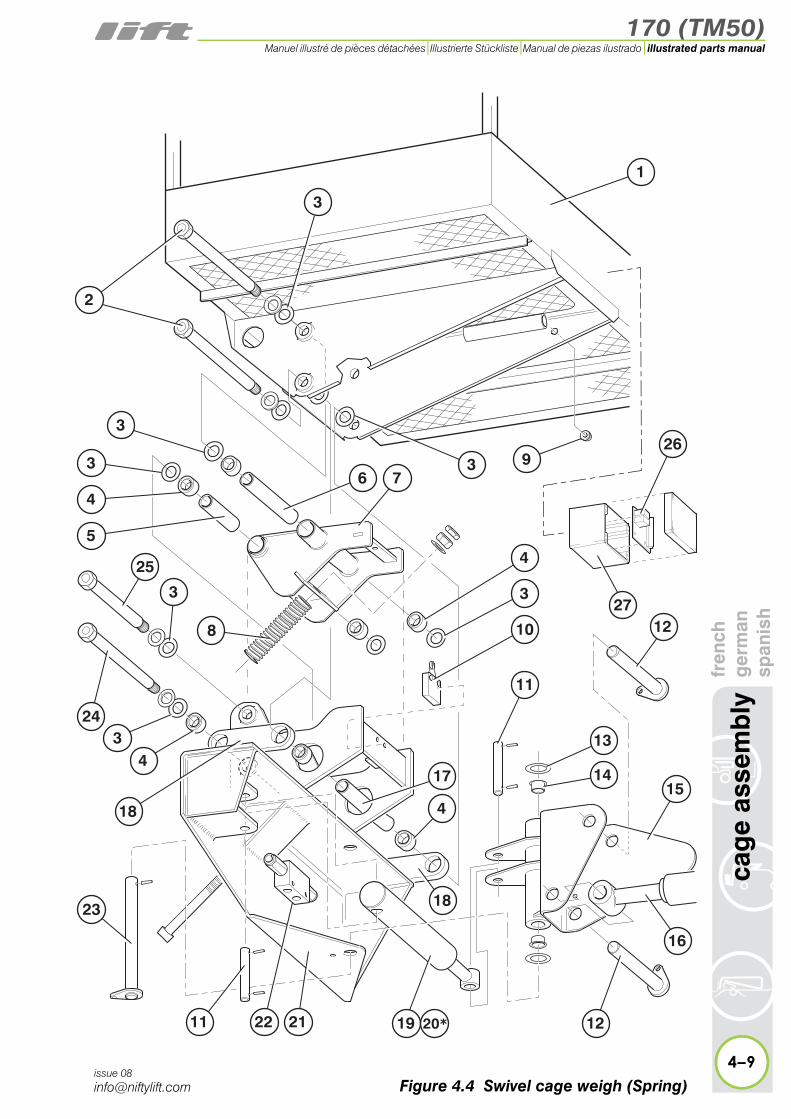
h4.4 Swivel cage weigh assembly (Spring)
Item Description Part Number
1 Cage P18166
2 Pivot pin - 274 mm P17942
3 Washer P18058
4 Bearing P18080
5 Distance tube - 111 mm P17974
6 Distance tube - 183 mm P17975
7 Inner frame P18162
8 Spring P18079
9 Grommet P14456
10 Microswitch P18150
11 Pivot pin - 95 mm P11979
12 Pivot pin - 130 mm P16610
13 Washer P10035
14 Bush P12250
15 Swivel bracket P11654
16Levelling cylinderSee “Levelling cylin-der” on page 3-8.
P22974
17 Diistance tube - 182mm P17944
18 Swivel arm P17938
19 Rotation cylinder P12660
20 * Seal kit for item 19 P13048
21 Lower chassis P18163
22 Check valve P10665
23 Pivot pin - 235 mm P11978
24 Pivot pin - 251 mm P17941
25 Pivot pin - 208 mm P17940
26 PCB P16164
4–8issue 08
27 Box and lid P11910
* Not illustrated
170 (TM50)
fren
chg
erm
ansp
anis
hca
ge
asse
mb
ly
4–9
illustrated parts manualManuel illustré de pièces détachées Illustrierte Stückliste Manual de piezas ilustrado
issue 08
1
25
3
76
3
4
3
10
11
12
17
4
9
13
14
27
15
263
2
3
23
243
4
3
8
11 19 12
16
18
2122
4
5
18
20*
Figure 4.4 Swivel cage weigh (Spring)

170 (TM50)illustrated parts manual Manuel illustré de pièces détachées Illustrierte Stückliste Manual de piezas ilustrado
ass
emb
lyfr
ench
ger
man
span
ish
4.5 Swivel cage weigh assembly (Load Cell)Item Description Part Number
1 Cage P17050
2 Step P16905
3 Lower chassis P17257
4 Rubber grommet P16983
5Load cell
1.1m cable2.4m cable
P18179P29179
6 Check valve P10665
7 Pivot pin - 95 mm P11979
8 Pivot pin - 235 mm P11978
9 Rotation cylinder P12660
10 * Seal kit for item 9 P13048
11 Swivel bracket P11654
12 Bush P12250
13 Washer P10035
14 Grommet P14456
15 Pivot pin - 130 mm P16610
16Levelling cylinderSee “Levelling cylin-der” on page 3-8.
P22974
17 Pivot pin - 91 mm P12048
18 PCB - 2000kg12v P18185
19 Box assembly P17133
4–10
cag
e
issue 08

170 (TM50)
fren
chg
erm
ansp
anis
hca
ge
asse
mb
ly
4–11
illustrated parts manualManuel illustré de pièces détachées Illustrierte Stückliste Manual de piezas ilustrado
issue 08
17
18
14
15
2
11
9
4
3
15
1
16
1312
4 5
19
76
86
10*
Figure 4.5 Swivel cage weigh (Load cell)
170 (TM50)illustrated parts manual Manuel illustré de pièces détachées Illustrierte Stückliste Manual de piezas ilustrado
age
asse
mb
lyfr
ench
ger
man
span
ish
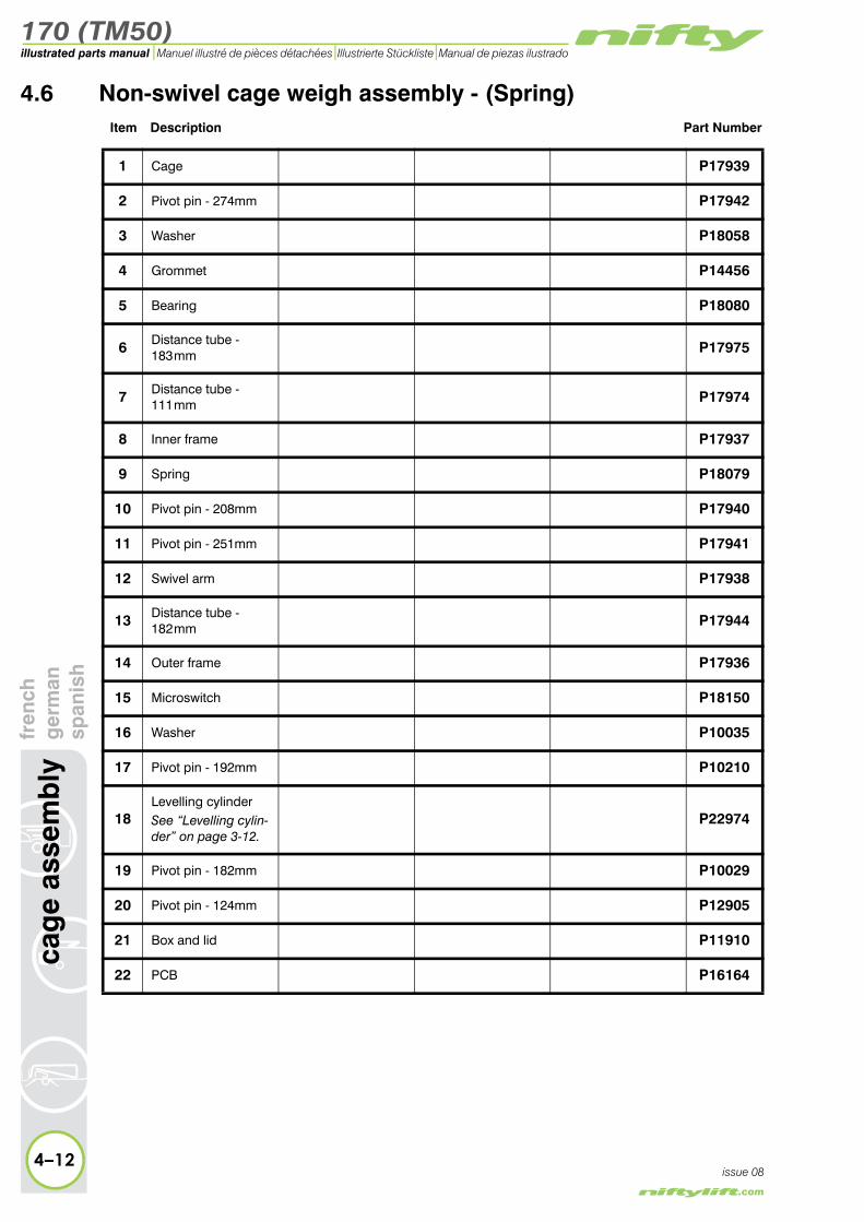
4.6 Non-swivel cage weigh assembly - (Spring)Item Description Part Number
1 Cage P17939
2 Pivot pin - 274mm P17942
3 Washer P18058
4 Grommet P14456
5 Bearing P18080
6 Distance tube - 183 mm P17975
7 Distance tube - 111 mm P17974
8 Inner frame P17937
9 Spring P18079
10 Pivot pin - 208mm P17940
11 Pivot pin - 251mm P17941
12 Swivel arm P17938
13 Distance tube - 182 mm P17944
14 Outer frame P17936
15 Microswitch P18150
16 Washer P10035
17 Pivot pin - 192mm P10210
18Levelling cylinderSee “Levelling cylin-der” on page 3-12.
P22974
19 Pivot pin - 182mm P10029
20 Pivot pin - 124mm P12905
21 Box and lid P11910
4–12
c
issue 08
22 PCB P16164

170 (TM50)
fren
chg
erm
ansp
anis
hca
ge
asse
mb
ly
4–13
illustrated parts manualManuel illustré de pièces détachées Illustrierte Stückliste Manual de piezas ilustrado
issue 08
1
3
5
3
3
7
8
15
9
5
3
14
12
3
2
42122
3
10
11
13
5
18 17
16
16
5
6
12
20 19
Figure 4.6 Non-swivel cage weigh (Spring)

170 (TM50)illustrated parts manual Manuel illustré de pièces détachées Illustrierte Stückliste Manual de piezas ilustrado
4.7 Non- swivel cage weigh assembly (Load Cell)Item Description Part Number
1 Pin - 124mm P12905
2Levelling cylinderSee “Levelling cylin-der” on page 3-8.
P22974
3 Pin - 110mm P13157
4 Grommet P14456
5Load cell
1.1m cable2.4m cable
P18179P29179
6 Rubber grommet P16983
7 Lower chassis P16866
8 Pin - 192mm P10210
9 PCB - 2000kg12v P18185
4–14
cag
e as
sem
bly
fren
chg
erm
ansp
anis
h
issue 08
10 Box assembly P17133

170 (TM50)
fren
chg
erm
ansp
anis
hca
ge
asse
mb
ly
4–15
illustrated parts manualManuel illustré de pièces détachées Illustrierte Stückliste Manual de piezas ilustrado
issue 08
76
3
8
54
2
10
1
6
8
Figure 4.7 Non-swivel cage weigh (Load cell)

170 (TM50)illustrated parts manual Manuel illustré de pièces détachées Illustrierte Stückliste Manual de piezas ilustrado
yfr
ench
ger
man
span
ish
4.8 Control valve assemblyItem Description Part Number
1 Valve seal kit P10707
2 Interface seal kit P10706
3 Lever (150mm) P70346
4 Stroke restrictor/Return spring P16384
5Spool AS
CS(Swivel, level spool ONLY)
P15510P15512
6Valve assembly - (Non-swivel) 5 spool
(Swivel) 6 spoolP15517P18700
7
Pressure relief valveTelescope spoolLevelling spool
Boom 3 spool
P10879P10879P15840
8 Pressure relief valve P70335
9 Stroke restrictor/End cap P16383
10 Lever cap P70338
11 Rubber boot P12225
12 Knob ONLY P28677
13 * Carry-over valve P10548
14 * Outlet manifold P16507
4–16
cag
e as
sem
bl
issue 08
* Items 13 & 14 applicable to Traction Drive machines only

170 (TM50)
fren
chg
erm
ansp
anis
hca
ge
asse
mb
ly
4–17
illustrated parts manualManuel illustré de pièces détachées Illustrierte Stückliste Manual de piezas ilustrado
issue 08
3
14
4
12
13
6
78
9
10
11
2
1
5
Figure 4.8 Control valve
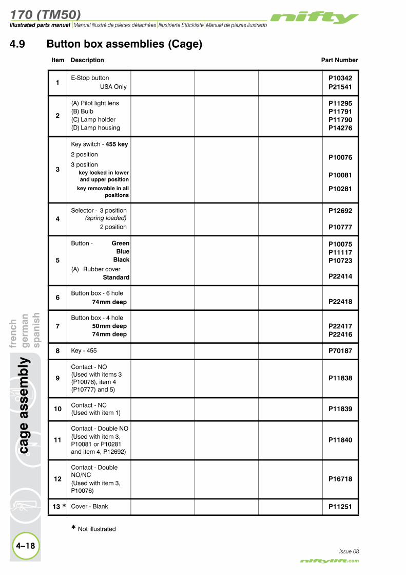
170 (TM50)illustrated parts manual Manuel illustré de pièces détachées Illustrierte Stückliste Manual de piezas ilustrado
cag
e as
sem
bly
fren
chg
erm
ansp
anis
h4.9 Button box assemblies (Cage)
Item Description Part Number
1E-Stop button
USA OnlyP10342P21541
2
(A) Pilot light lens(B) Bulb(C) Lamp holder(D) Lamp housing
P11295P11791P11790P14276
3
Key switch - 455 key
2 position
3 positionkey locked in lowerand upper position
key removable in all positions
P10076
P10081
P10281
4Selector - 3 position
(spring loaded)2 position
P12692
P10777
5
Button - GreenBlue
Black
(A) Rubber coverStandard
P10075P11117P10723
P22414
6Button box - 6 hole
74 mm deep P22418
7Button box - 4 hole
50 mm deep74 mm deep
P22417P22416
8 Key - 455 P70187
9
Contact - NO(Used with items 3 (P10076), item 4 (P10777) and 5)
P11838
10 Contact - NC(Used with item 1) P11839
11
Contact - Double NO(Used with item 3, P10081 or P10281 and item 4, P12692)
P11840
12
Contact - Double NO/NC(Used with item 3, P10076)
P16718
4–18issue 08
13 * Cover - Blank P11251
* Not illustrated

170 (TM50)
fren
chg
erm
ansp
anis
hca
ge
asse
mb
ly
4–19
illustrated parts manualManuel illustré de pièces détachées Illustrierte Stückliste Manual de piezas ilustrado
issue 08
6
7
1
2
3
4
2
5
1
2
5
3
11109 12
8
A
A
B
C
D
1
3
4
5
2
Figure 4.9 Button boxes (Cage)

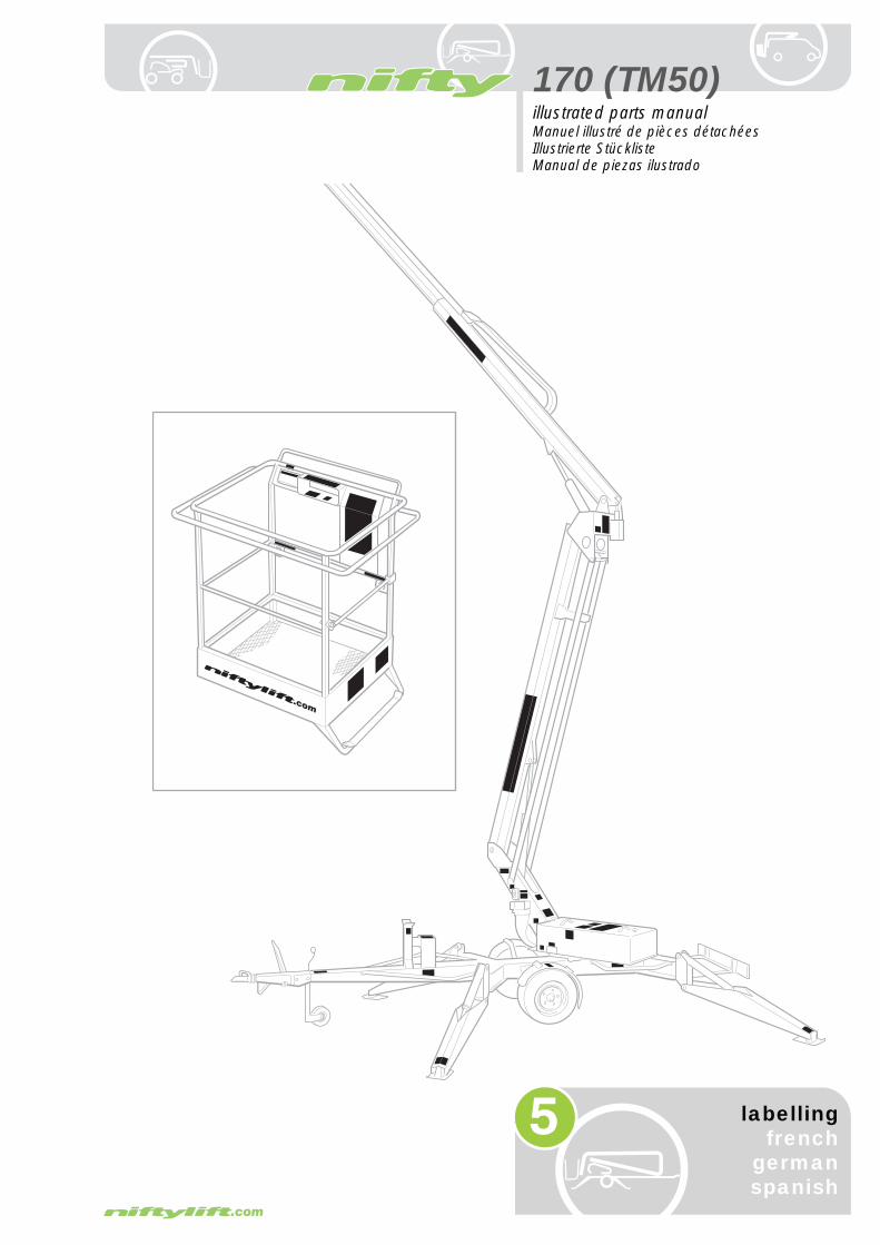
170 (TM50)
5
illustrated parts manualManuel illustré de pièces détachéesIllustrierte StücklisteManual de piezas ilustrado
labellingfrench
germanspanish

170 (TM50)illustrated parts manual Manuel illustré de pièces détachées Illustrierte Stückliste Manual de piezas ilustrado
lab
ellin
gfr
ench
ger
man
span
ish
5.1 Label locations 170Item Description Part Number
1 Harness point P14883
french P14883
german P14883
spanish P14883
dutch P14883
italian P14883
2 Button box (without cage weigh) Bi-energy (Petrol)Bi-energy (Diesel)
AC or DC
P15924P16684P15925
frenchP15924P16684P15925
germanP15924P16684P15925
spanishP15924P16684P15925
dutchP15924P16684P15925
italianP15924P16684P15925
3 Button box (with cage weigh) Bi-energy (Petrol)Bi-energy (Diesel)
AC or DC
P17457P17213P17212
frenchP17457P17213P17212
germanP17457P17213P17212
spanishP17457P17213P17212
dutchP17457P17213P17212
italianP17457P17213P17212
5–2issue 06

170 (TM50)
fren
chg
erm
ansp
anis
hla
bel
ling
5–3
illustrated parts manualManuel illustré de pièces détachées Illustrierte Stückliste Manual de piezas ilustrado
issue 06
39 15
38 37 33
16
34
17
6
5
11
25 15
25 26
24
35 36
292933
28
3031
25
32
16
23
27
27
19
15
4
2034 16
22
18
21
34
2
1
14
6 75
8 9
10
11
1
1213
15
Please refer to Figure 5.3 & 5.4for representation of labels
Figure 5.1 Label locations 170

170 (TM50)illustrated parts manual Manuel illustré de pièces détachées Illustrierte Stückliste Manual de piezas ilustrado
5–4
lab
ellin
gfr
ench
ger
man
span
ish
issue 06
5.1 continuedItem Description Part Number
4 If emergency stop disabled P14864
french P14865
german P14866
spanish P14867
dutch P16628
italian P16651
5 Cage levelling P10853
french P10853
german P10853
spanish P10853
dutch P10853
italian P10853
6 Control levers - Cage P14927
french P14927
german P14927
spanish P14927
dutch P14927
italian P14927
7 Controls - Cage rotation (OPTION) P15634
french P15634
german P15634
spanish P15634
dutch P15634
italian P15634
8 Cage gate warning P18432
french P18432
german P18432
spanish P18432
dutch P18432
italian P18432
9 Overload warning P18848
french P18849
german P18850
spanish P18851
dutch P18852
italian P18853

170 (TM50)
fren
chg
erm
ansp
anis
hla
bel
ling
5–5
illustrated parts manualManuel illustré de pièces détachées Illustrierte Stückliste Manual de piezas ilustrado
issue 06
39 15
38 37 33
16
34
17
6
5
11
25 15
25 26
24
35 36
292933
28
3031
25
32
16
23
27
27
19
15
4
2034 16
22
18
21
34
2
1
14
6 75
8 9
10
11
1
1213
15
Please refer to Figure 5.3 & 5.4for representation of labels
Figure 5.1 Label locations 170
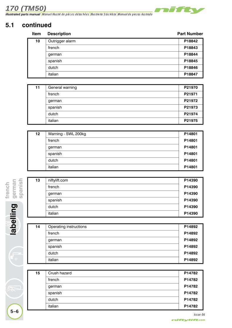
170 (TM50)illustrated parts manual Manuel illustré de pièces détachées Illustrierte Stückliste Manual de piezas ilustrado
5–6
lab
ellin
gfr
ench
ger
man
span
ish
issue 06
5.1 continuedItem Description Part Number
10 Outrigger alarm P18842
french P18843
german P18844
spanish P18845
dutch P18846
italian P18847
11 General warning P21970
french P21971
german P21972
spanish P21973
dutch P21974
italian P21975
12 Warning - SWL 200kg P14801
french P14801
german P14801
spanish P14801
dutch P14801
italian P14801
13 niftylift.com P14390
french P14390
german P14390
spanish P14390
dutch P14390
italian P14390
14 Operating instructions P14892
french P14892
german P14892
spanish P14892
dutch P14892
italian P14892
15 Crush hazard P14782
french P14782
german P14782
spanish P14782
dutch P14782
italian P14782

170 (TM50)
fren
chg
erm
ansp
anis
hla
bel
ling
5–7
illustrated parts manualManuel illustré de pièces détachées Illustrierte Stückliste Manual de piezas ilustrado
issue 06
39 15
38 37 33
16
34
17
6
5
11
25 15
25 26
24
35 36
292933
28
3031
25
32
16
23
27
27
19
15
4
2034 16
22
18
21
34
2
1
14
6 75
8 9
10
11
1
1213
15
Please refer to Figure 5.3 & 5.4for representation of labels
Figure 5.1 Label locations 170

170 (TM50)illustrated parts manual Manuel illustré de pièces détachées Illustrierte Stückliste Manual de piezas ilustrado
lab
ellin
gfr
ench
ger
man
span
ish
5.1 continuedItem Description Part Number
16 Coupling instructions P14896
french P14897
german P14898
spanish P14899
dutch P16263
italian P17267
17 Nifty 170 P14600
french P14600
german P14600
spanish P14600
dutch P14600
italian P14600
18 Head protection P14921
french P14921
german P14921
spanish P14921
dutch P14921
italian P14921
19 Component stability P19708
french P19709
german P19710
spanish P19711
dutch P19712
italian P19713
20 Button box cage weigh - 170H170M
non cage weigh - 170H170M
P17219P21055P15881P21131
21 Control levers - Base P14926
french P14926
german P14926
spanish P14926
dutch P14926
italian P14926
5–8issue 06

170 (TM50)
fren
chg
erm
ansp
anis
hla
bel
ling
5–9
illustrated parts manualManuel illustré de pièces détachées Illustrierte Stückliste Manual de piezas ilustrado
issue 06
39 15
38 37 33
16
34
17
6
5
11
25 15
25 26
24
35 36
292933
28
3031
25
32
16
23
27
27
19
15
4
2034 16
22
18
21
34
2
1
14
6 75
8 9
10
11
1
1213
15
Please refer to Figure 5.3 & 5.4for representation of labels
Figure 5.1 Label locations 170
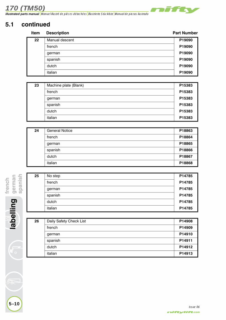
170 (TM50)illustrated parts manual Manuel illustré de pièces détachées Illustrierte Stückliste Manual de piezas ilustrado
lab
ellin
gfr
ench
ger
man
span
ish
5.1 continuedItem Description Part Number
22 Manual descent P19090
french P19090
german P19090
spanish P19090
dutch P19090
italian P19090
23 Machine plate (Blank) P15383
french P15383
german P15383
spanish P15383
dutch P15383
italian P15383
24 General Notice P18863
french P18864
german P18865
spanish P18866
dutch P18867
italian P18868
25 No step P14785
french P14785
german P14785
spanish P14785
dutch P14785
italian P14785
26 Daily Safety Check List P14908
french P14909
german P14910
spanish P14911
dutch P14912
italian P14913
5–10issue 06
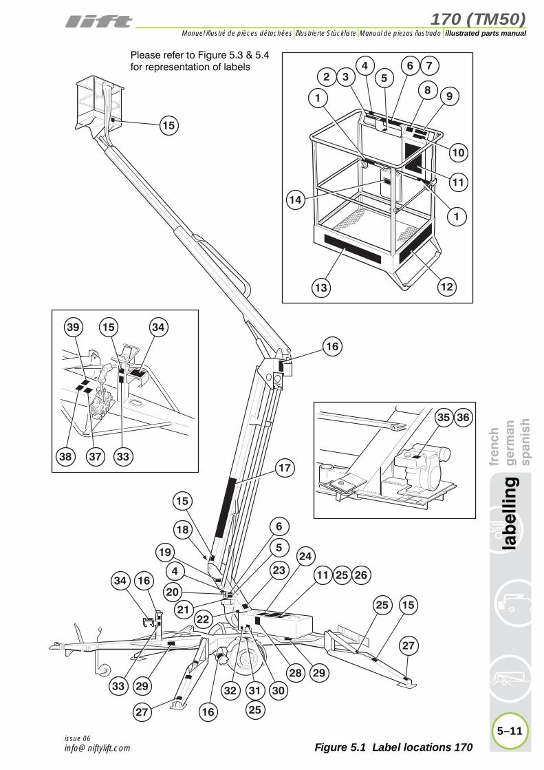
170 (TM50)
fren
chg
erm
ansp
anis
hla
bel
ling
5–11
illustrated parts manualManuel illustré de pièces détachées Illustrierte Stückliste Manual de piezas ilustrado
issue 06
39 15
38 37 33
16
34
17
6
5
11
25 15
25 26
24
35 36
292933
28
3031
25
32
16
23
27
27
19
15
4
2034 16
22
18
21
34
2
1
14
6 75
8 9
10
11
1
1213
15
Please refer to Figure 5.3 & 5.4for representation of labels
Figure 5.1 Label locations 170

170 (TM50)illustrated parts manual Manuel illustré de pièces détachées Illustrierte Stückliste Manual de piezas ilustrado
5–12
lab
ellin
gfr
ench
ger
man
span
ish
5.1 continuedItem Description Part Number
27 Point load - 13.0 kN 170H170M
P14965P14694
french 170H170M
P14965P14694
german 170H170M
P14965P14694
spanish 170H170M
P14965P14694
dutch 170H170M
P14965P14694
italian 170H170M
P14965P14694
28 Battery charging P14904
french P14905
german P14906
spanish P14907
dutch P16746
italian P16662
29 Outriggers 170H170M
P14841P18634
french 170H170M
P14842P14856
german 170H170M
P14843P14857
spanish 170H170M
P14844P14858
dutch 170H170M
P16262P17306
italian 170H170M
P16636P17836
30 Battery - Isolator P18600
french P18600
german P18600
spanish P18600
dutch P18600
italian P18600
31 Tyre pressure - 65 psi P14876
french P14876
german P14876
spanish P14876
dutch P14876
italian P14876
issue 06

170 (TM50)
fren
chg
erm
ansp
anis
hla
bel
ling
5–13
illustrated parts manualManuel illustré de pièces détachées Illustrierte Stückliste Manual de piezas ilustrado
issue 06
39 15
38 37 33
16
34
17
6
5
11
25 15
25 26
24
35 36
292933
28
3031
25
32
16
23
27
27
19
15
4
2034 16
22
18
21
34
2
1
14
6 75
8 9
10
11
1
1213
15
Please refer to Figure 5.3 & 5.4for representation of labels
Figure 5.1 Label locations 170

170 (TM50)illustrated parts manual Manuel illustré de pièces détachées Illustrierte Stückliste Manual de piezas ilustrado
5–14
lab
ellin
gfr
ench
ger
man
span
ish
5.1 continuedItem Description Part Number
32 Noise warning - 73 dB P17123
french P17123
german P17123
spanish P17123
dutch P17123
italian P17123
33 Boom clamp P19740
french P14837
german P14838
spanish P14839
dutch P16847
italian P16798
34 Hydraulic outrigger controls P14922
french P14923
german P14924
spanish P14925
dutch P16267
italian P17834
35 Petrol OFF ( Petrol engine ONLY) P19055
french P19055
german P19055
spanish P19055
dutch P19055
italian P19055
36 Diesel ( Diesel engine ONLY) P14414
french P14414
german P14414
spanish P14414
dutch P14414
italian P14414
37 Traction drive - Engage P18890
french P18890
german P18890
spanish P18890
dutch P18890
italian P18890
issue 06

170 (TM50)
fren
chg
erm
ansp
anis
hla
bel
ling
5–15
illustrated parts manualManuel illustré de pièces détachées Illustrierte Stückliste Manual de piezas ilustrado
issue 06
39 15
38 37 33
16
34
17
6
5
11
25 15
25 26
24
35 36
292933
28
3031
25
32
16
23
27
27
19
15
4
2034 16
22
18
21
34
2
1
14
6 75
8 9
10
11
1
1213
15
Please refer to Figure 5.3 & 5.4for representation of labels
Figure 5.1 Label locations 170

170 (TM50)illustrated parts manual Manuel illustré de pièces détachées Illustrierte Stückliste Manual de piezas ilustrado
5.1 continuedItem Description Part Number
38 Traction drive - Apply handbrake before release P18975
french P18975
german P18975
spanish P18975
dutch P18975
italian P18975
39 Traction drive - On slope P18976
french P18976
german P18976
spanish P18976
dutch P18976
italian P18976
5–16
lab
ellin
gfr
ench
ger
man
span
ish
issue 06

170 (TM50)
fren
chg
erm
ansp
anis
hla
bel
ling
5–17
illustrated parts manualManuel illustré de pièces détachées Illustrierte Stückliste Manual de piezas ilustrado
issue 06
39 15
38 37 33
16
34
17
6
5
11
25 15
25 26
24
35 36
292933
28
3031
25
32
16
23
27
27
19
15
4
2034 16
22
18
21
34
2
1
14
6 75
8 9
10
11
1
1213
15
Please refer to Figure 5.3 & 5.4for representation of labels
Figure 5.1 Label locations 170

170 (TM50)illustrated parts manual Manuel illustré de pièces détachées Illustrierte Stückliste Manual de piezas ilustrado
5–18
lab
ellin
gfr
ench
ger
man
span
ish
5.2 Label locations TM50 (USA)Item Description Part Number
1 Harness point P14883
2 Button box (without cage weigh) Bi-energy (Petrol)Bi-energy (Diesel)
AC or DC
P15924P16684P15925
3 Button box (with cage weigh) Bi-energy (Petrol)Bi-energy (Diesel)
AC or DC
P17457P17213P17212
4 If emergency stop disabled P14864
5 Cage levelling P10853
6 Control levers - Cage P14927
7 Controls - Cage rotation (OPTION) P15634
8 Cage gate warning P18432
9 Outrigger alarm P18842
11 General warning P21970
13 niftylift.com P14390
14 Operating instructions P14892
15 Coupling instructions P14896
16 Crush hazard P14782
18 Head protection P14921
19 Component stability P19708
20 Button box TM50HTM50M
P15881P21131
21 Control levers - Base P14926
22 Manual descent P19090
23 Machine plate (Blank) P15383
24 General Notice P18863
25 No step P14785
26 Daily Safety Check List P14908
27 Point load - 13.0 kN TM50HTM50M
P14965P14964
28 Battery - Isolator P18600
29 Outriggers TM50HTM50M
P14841P18634
30 Battery charging P14904
31 Tyre pressure - 65 psi P14876
32 Noise warning - 73 dB P17123
33 Boom clamp P19740
34 Outrigger controls P14922
35 Petrol OFF ( Petrol engine ONLY) P19055
36 Diesel only (Diesel engine ONLY) P14414
37 Traction drive - Engage P18890
38 Traction drive - Apply handbrake before release P18975
39 Traction drive - On slope P18976
issue 06

170 (TM50)
fren
chg
erm
ansp
anis
hla
bel
ling
5–19
illustrated parts manualManuel illustré de pièces détachées Illustrierte Stückliste Manual de piezas ilustrado
issue 06
39 16
40
38 4237 33
16
34
44
25
43
6
5
11
45
25 26
24
35 36
292933
28
3031
25
32
16
23
27
27
16
25
19
15
4
2034 16
22
18
21
34
2
1
14
6 75
8 9
10
11
1
4113
15
Please refer to Figure 5.3 and 5.4for representation of labels
Figure 5.2 Label locations TM50 (USA)

170 (TM50)illustrated parts manual Manuel illustré de pièces détachées Illustrierte Stückliste Manual de piezas ilustrado
5.2 continuedItem Description Part Number
40 * Footswitch P14884
41 * SWL - 500 lbs P17328
42 * Max Towing speed P17140
43 * Nifty TM50 (Grey) P14614
44 * Carb. Regulations P15334
45 * Rotating machinery P15010
* USA only
5–20
lab
ellin
gfr
ench
ger
man
span
ish
issue 06
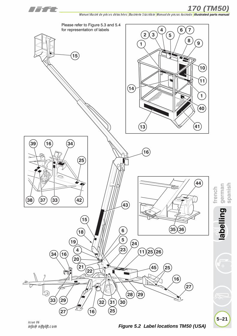
170 (TM50)
fren
chg
erm
ansp
anis
hla
bel
ling
5–21
illustrated parts manualManuel illustré de pièces détachées Illustrierte Stückliste Manual de piezas ilustrado
issue 06Figure 5.2 Label locations TM50 (USA)
39 16
40
38 4237 33
16
34
44
25
43
6
5
11
45
25 26
24
35 36
292933
28
3031
25
32
16
23
27
27
16
25
19
15
4
2034 16
22
18
21
34
2
1
14
6 75
8 9
10
11
1
4113
15
Please refer to Figure 5.3 and 5.4for representation of labels

170 (TM50)
5–22
lab
ellin
gfr
ench
ger
man
span
ish
illustrated parts manual Manuel illustré de pièces détachées Illustrierte Stückliste Manual de piezas ilustrado
issue 06
P14785/001
e-mail: [email protected]
HYD. CCT D ISSUE
ELEC. CCT D ISSUE
Deg.MAX. ALLOWABLE INCLINATION
P15383
+
A
V
bar
m/s
N
kg
kg
kg
AMPS
MAXIMUM VOLTAGE
MAXIMUM HYDRAULIC PRESSURE
MAXIMUM WIND SPEED
MAXIMUM PULL
MAXIMUM SAFE WORKING LOAD
RATED LOAD PERSONS
WEIGHT
YEAR OF MANUFACTURE
TYPE
SERIAL No
TEL 01908 223456 : FAX 01908 312733 MILTON KEYNES MK13 0ER ENGLAND
NIFTYLIFT LTD.,FINGLE DRIVE,STONEBRIDGE
P14921/001
P14926/001
P14927/001
P15634/01
13.0kN
P14965/01
POSITION VEHICLE & TRAILER ON LEVEL GROUND BEFORE ATTEMPTING TO COUPLE / DE-COUPLE
Coupling instructions
1. Depress the trigger on the lever mechanism and lift the handle upwards and forwards.2. Place the unlocked coupling head onto the tow ball and apply slight downwards pressure. The head will automatically lock onto the ball.3. Ensure the trigger has returned to its free position before attempting to tow, and that the coupling head is secure on the towing ball.4. Connect the breakaway cable to the towing vehicle hitch - not to the tow ball itself. 5. Connect the lighting plug to the vehicle and check the light functions.6. Raise the jockey wheel to its stowed position and secure for transit.
De-coupling instructions
1. Apply trailer handbrake & chock wheels.2. Lower the jockey wheel to the ground. Disconnect the breakaway cable and lighting plug.3. Operate the handle by depressing the trigger and manually lift the coupling head clear of the towing ball or screw down the telescopic jockey wheel to achieve the same effect.
Handbrake operation
1. To operate the trailer parking brakes pull handbrake lever upwards and backwards. The spring loaded mechanism will engage and stay in the operated position until reset.2. To disengage the parking brakes, firmly grasp the handbrake lever and pull upwards. Depress the ratchet release button in the end of the handbrake lever and return lever to the horizontal position.
Care should be taken when operating the handbrake lever due to the forces involved in engaging the ratchet mechanism.
NOTICE
P14896/001
P15925/0010 I
P15924/010 I
P16684/010 I
0 IP17212/01
0 IP17457/01
0 IP17213/01
DANGERDeath or serious injury may
result if emergency stop switch is disabled, blocked
or inoperable.P14864/001
DANGER
P18842/02
IF TILT ALARM SOUNDS, DESCEND IMMEDIATELY AND CHECK OUTRIGGER/STABILISER SETTINGS.
P1478 /0
DANGERPELIGROACHTUNGGEVAAR
P14892/02
P15881/01
0
I
P17219/001
0
I
DANGER
P18848/01
IF OVERLOAD ALARM ACTIVATES, ALL FUNCTIONS WILL HALT. REMOVE EXCESS LOAD IMMEDIATELY IN A SAFE MANNER TO RESTORE FUNCTIONS.
13.0kN
P14964/001
P18600/01
+ -
+ -
P14883/02
P18432/01
READ THIS BEFORE OPERATING THIS MACHINETHIS NOTICE DOES NOT REPLACE THE OPERATING MANUAL WHICH SHOULD BE READ
BEFORE OPERATING THIS MACHINE FOR THE FIRST TIME
YOU MUST NOT OPERATE THIS MACHINE unless you have been trained in the safe operation of this machine. Training includes complete knowledge of the safety and operating instructions contained in the manufacturer's manuals, your employer's work rules and applicable governmental regulations. Inspect the machine before use to be sure it is operating properly and perform the safety checks listed in the operating manual and on the label under this canopy. This machine must be inspected / serviced as the operating manual requires.
ELECTROCUTION HAZARD THIS MACHINE IS NOT INSULATED
� Maintain a safe distance from electrical lines and apparatus, you must allow for machine sway, rock and sag and electrical lines swaying.� This machine does not provide protection from contact with or proximity to an electrically charged conductor. You must maintain clearance
of at least 3m (10 ft) between any part of the machine or its load and any electrical line or apparatus carrying over 50,000 volts. Further clearance of 1m (3ft) is required for every additional 10,000 volts or less.
EXPLOSION HAZARD
� Do not start the Niftylift if you can smell gasoline, liquid propane or diesel fuel.� The engine must be shut down while fuel tanks are being filled. Fuelling and battery charging must be done in a well ventilated area free of any naked flame or other sources of ignition which may cause fire or explosion.� Gasoline, liquid petroleum and diesel fuels are flammable.
HAZARDOUS SUBSTANCES AND ENVIRONMENTS� This machine contains several hazardous substances such as but not limited to:Battery acid, Hydraulic Fluid, Engine Coolant, Antifreeze, LPG, Diesel Fuel, Petrol, Engine Oil, Grease, Gasoline.� Covers and canopies should remain closed when the machine is in operation. Only trained personnel should carry out maintenance on the machine, ensuring at all times they protect themselves from electrical, heat and mechanical hazards.
DAMAGED OR MALFUNCTIONING MACHINE HAZARD� Do not use a damaged or malfunctioning machine.� If the machine malfunctions during operation or the tilt / outrigger alarm sounds stop all work and descend as soon as possible in a smooth controlled manner.
STABILITY HAZARD� The machine must be on smooth firm level surface or levelled using the outriggers (if fitted) before using the booms.� Do not use the machine in strong or gusty winds (over 12.5m/s (45kph or 28mph)).� Never exceed the platform capacity.
� Do not remove, alter or disable any components that in any way affect safety or stability. These include but is not limited to engines, batteries and tyres. IF IN ANY DOUBT CONTACT NIFTYLIFT IMMEDIATELY.TRAILERS, TRACKED & SELF DRIVE MACHINES:� All stabilisers or outriggers must be properly extended.� All jack feet must be lowered onto a firm footing.
SELF PROPELLED MACHINES:� Do not attempt to climb or descend slopes exceeding the stated limitations of the machine.Never traverse slopes exceeding 20%� Use with additional caution when operating the machine (in stowed position only) across uneven terrain, debris, unstable or slippery surface and near holes or drop-offs.
� Use only tyres specified by Niftylift, foam filled if specified.
COLLISION HAZARD� Head protection must be worn.� Operate machine with extreme caution. Use controls slowly for smooth operation and watch for obstructions which may strike persons or machine.� Make yourself familiar with the work area before using the machine, checking for overhead obstructions.
� Do not lower the boom unless the area below is free of obstructions or personnel.� Be aware of crushing hazards when gripping the handrail.
SELF PROPELLED MACHINES:� To prevent damage to the platform, raise the flyboom before driving up slopes or over uneven terrain.� Check the drive direction before moving the machine.
RESTRAINT HAZARD� All personnel in the platform shall wear a full body harness with a short lanyard secured to the designated harness point.� Do not climb, sit or stand on the platform rails.� Do not attempt to leave the platform by climbing down the booms.� Ensure the platform entry gate is
down before raising the booms.� Check that any tools or equipment being used in the platform are secure and cannot fall out of the platform.
PLATFORM OVERLOAD WARNING� If machine is fitted with an overload alarm, when it activates all functions will halt. Remove excess load immediately in a safe manner to restore functions. P20330/01
DANGER
P14801/003
80KG(177lbs)
80KG(177lbs)
40KG(88lbs)
WARNINGAVERTISSEMENT
WARNHINWEISADVERTENCIA
AVVERTENZAWAARSCHUWING
(440lbs)200KG
MAX12.5 m/s(28mph)
MAX
400N(90lbs)MAX
WARNING
P19708/01
Do not remove or replace, without Niftylift’s consent, any components critical to the aerial platform’s stability.
This includes, but is not limited to, engines, motors, batteries, wheels, ballast or any other substantial item.
If in doubt contact Niftylift immediately.
DAILY SAFETY CHECK LIST1. Check operating and safety manuals are legible and located in their box within the platform (if applicable).2. Check safety belts and hats.3. Check all decals and placards to see if in place and legible.4. Check platform is securely fastened to platform support.5. Check wheels and tyres.6. Check outriggers / stabilisers (if applicable) for condition, micro switch operation and security.7. Check batteries for condition, cleanliness, connectors and electrolyte levels. 8. Check engine oil and coolant levels (if applicable).9. Check Installation of all guards, covers and boom clamps.10. Check for loose, missing or damaged parts.11. Check all hydraulic hoses and electrical cables and wiring.12. Check hydraulic, fuel and air systems for leaks.13. Do not exceed rated platform capacity.14. Check foot pedal for proper operation (if applicable).15. Check all operating and emergency controls - select an area free from obstructions and hazards. Exercise extreme caution throughout the checking procedure especially when checking brakes.16. Check operation of emergency handpump.17. Check all brakes and lights.18. Check tilt sensor / alarm horn and beacons.19. Check high engine and / or high drive limit switches.20. Check and refer to operating and workshop manual for further daily / periodic checks and inspections.
DO NOT OPERATE A MALFUNCTIONING MACHINEP14908/001
NOTICE
BEFORE USERefer to the operating manual located in the platform and perform the daily maintenance / check routine as required. Read all labels on the machine.
ACTIVATING THE MACHINE1. Ensure all red Emergency Stops are out.2. Manual Outriggers: Select either platform or base controls by turning the key switch on the base control station. (Note: The platform key switch must be switched to ‘On’ to operate from the platform)3. Select a power option by turning the selector switch in the platform. (Note: On Bi-energy machines, if ‘Battery’ ( ) is selected and the engine is running, the machine will still use the battery’s power) 2. Hydraulic Outriggers: Turn the key switch at the ground or platform control station to ‘On’ position to activate the controls.3. If no other power option is already running, the 'Instinctive' control circuit will default to battery power. (If applicable)4. All Machines: To start the engine turn the selector to the ‘Start’ ( ) position, the engine will fire. (If applicable)5. Cold diesel engines: Push and hold the ‘Glow’ button ( ) for 10 seconds then turn the selector to the ‘Start’ position and the engine will fire.
EMERGENCY STOP Pushing in an emergency stop will stop all functions and turn the engine off.
EMERGENCY HAND PUMPIn the event that the controls fail or the operator becomes incapacitated the booms can be operated by using the hand pump adjacent to the ground controls.
LOW BATTERY WARNING (Battery models)
If the siren sounds and operations become intermittent, the batteries need charging. Switch to engine power or charge the machine immediately. (Note: This feature is optional and may not be fitted to this machine)
TO OPERATE OUTRIGGERS1. Position the Niftylift on firm, level ground. Never work with base across or adjacent to any slope.2. Position the Niftylift, bearing in mind range of boom movement so that any overhead obstruction or possible hazards such as, but not limited to: power cables, telephone lines, drains, manhole covers etc. are avoided.3. If the load bearing capacity of the ground is in any doubt the machine must not be used.4. Apply handbrake, chock wheels and cordon off area using appropriate cones, barriers and flags.5. Release boom travelling clamp.6. To deploy the outriggers refer to the decals at the outrigger control station (hydraulic) or beside the outriggers (manual).
ALWAYS LOWER BOOMS FULLY BEFORE ADJUSTING, RAISING, RETRACTING OR MOVING THE OUTRIGGERS IN ANY WAY.
TO OPERATE BOOMS To operate from ground or platform:
1. Press and hold the green power button (or footswitch).2. Slowly move the desired control according to the markings on the control panel.
AFTER USE1. Return the machine to the stowed position. 2. Turn the key switch to the 'Off' position.3. Remove all keys. Chock wheels.
READ THIS BEFORE OPERATING THIS MACHINETHIS NOTICE DOES NOT REPLACE THE OPERATING MANUAL WHICH SHOULD BE READ BEFORE OPERATING
THIS MACHINE FOR THE FIRST TIME
P18863/01
NOTICE
P21131/01
0
P21055/001
0P19090/02
19
24
26
1
20 21
22
14
16
18
2 3
4
5
7
6
8 10
9
11 12
15
23
27
28
25
Figure 5.3 Labels 1-28
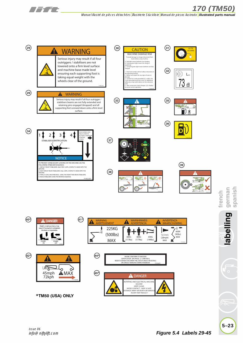
170 (TM50)
fren
chg
erm
ansp
anis
hla
bel
ling
5–23
illustrated parts manualManuel illustré de pièces détachées Illustrierte Stückliste Manual de piezas ilustrado
issue 06
P14414/001
1 2 3 4
1
2 4
3
TO PREVENT UNNECESSARY LOADING ON THE MACHINE USE THE FOLLOWING STABILISER SEQUENCE:1. DEPLOY FRONT STABILISERS (3&4) FIRST, UNTIL CONTACT IS MADE WITH THE GROUND.2. NEXT DEPLOY REAR STABILISERS (1&2), UNTIL CONTACT IS MADE WITH THE GROUND.3. FINALLY LEVEL MACHINE BASE, USING THE FRONT THEN REAR STABILISERS.4. RAISE STABILISERS USING THE REVERSE SEQUENCE.
STABILISER IDENTIFICATION
PUSH DOWN AND HOLD LEVER TO ACTIVATE STABILISER CONTROLLEVERS
P14922/001
NOTICEP18890/01
P17140/002
MAX45mph72kph
P15334/01
ENGINE CONFORMS TO EMISSIONCERTIFICATION : EPA PHASE -2 / CARB TIER-2
REFER TO HONDA DOCUMENT PWL 50975A (9603) FOR DETAILSOR CONSULT MANUFACTURERS HANDBOOK
DANGERROTATING AND ELECTRICAL MACHINE
HAZARD-KEEP CLEAR-
AVOID CONTACT - KEEP A SAFE DISTANCE AWAY OR DEATH OR SERIOUS
INJURY MAY RESULT.?P15010/001
Death or serious injury may result if footswitch is disabled,
blocked or inoperable.
DANGER
POWERON
POWEROFF
P14884/02
>100
P16541/02
P19055/01
65 PSI(4.5 BAR)
P14876/001
WARNINGSerious injury may result if all four outriggers / stabilisers are not lowered onto a firm level surface and machine base made level ensuring each supporting foot is taking equal weight with the wheels clear of the ground.
P14841/001
LWA
73 dB
MACHINE DAMAGE RISKTo avoid damage to charger disconnect from
mains before using machine.
A. Red light means batteries are charging.B. Pulsing green light means the charge is equalising.C. Constant green light means batteries are fully charged.
1. Read and comply with all safety instructions in the operating manual.2. Before use inspect for any signs of wear or damage.3. Connect to 3-wire grounded A.C. outlet. Use 3-wire grounded extension cord. For additional safety use a trip switch device on the extension cord.4. After connection check charger L.E.D. display to ensure correct operation.
CAUTION
P14904/001
Serious injury may result if all four outrigger / stabilisers beams are not fully extended and
retaining pins engaged (dropped) and all supporting feet screwed down onto a firm level
surface.
WARNING
P18634/01
P19740/01
P18975/02
P17328/001
80KG(177lbs)
80KG(177lbs)
65KG(144lbs)
WARNINGAVERTISSEMENT
WARNHINWEISADVERTENCIA
AVVERTENZAWAARSCHUWING
(500lbs)225KG
MAX12.5 m/s(28mph)
MAX
400N(90lbs)MAX
29
29
34
36
3533
37
38
39
42* 44*
45*
40* 41*
*TM50 (USA) ONLY
3130
32
Figure 5.4 Labels 29-45


170 (TM50)
6
illustrated parts manualManuel illustré de pièces détachéesIllustrierte StücklisteManual de piezas ilustrado
hydraulic hosesfrench
germanspanish

170 (TM50)illustrated parts manual Manuel illustré de pièces détachées Illustrierte Stückliste Manual de piezas ilustrado
6–2
hyd
raul
ic h
ose
sfr
ench
ger
man
span
ish
6.1 Hose kit 170H (TM50)Number Description french german spanish
1Cage control to base - return
2Base control to cage - pressure
3Base control to cage - slew
4Base control to cage - slew
5Cage control to RAM 1 - pilot
6Cage control to RAM 1 - pressure
7Base control toRAM 1 - pilot
8Base control toRAM 1 - pressure
9Cage control to RAM 2 - pilot
10Cage control to RAM 2 - pressure
11Base control toRAM 2 - pressure
12Base control toRAM 2 - pilot
13 RAM 1 - pilot link
14 RAM 2 - pilot link
15 Base control to slew
16 Base control to slew
17Pump dump toHand pump
18 Pump to tank - return
19Cage control to levelling ram (slave)
20Cage control to levelling ram (slave)
21Cage control to telescoping ram - pilot
22Cage control to telescoping ram - pressure
23Cage control to levelling ram (master)
24Cage control to levelling ram (master)
issue 05

170 (TM50)
fren
chg
erm
ansp
anis
hh
ydra
ulic
ho
ses
6–3
illustrated parts manualManuel illustré de pièces détachées Illustrierte Stückliste Manual de piezas ilustrado
issue 05
���
��
���
�
����
�
�
����
����
����
��
��
� � � �
���
�����
����
��
��
����
�����
������
����
�������
��������
����
����
����
���
���������
���
����
����
����������
����
������
��
�� �
������
��
����
����
������
��
��
�
�
�
�
�
�
�
��
��
��
��
��
��
��
��
��
��
��
��
��
��
��
��
��
��
��
��
��
��
��
��
��
��
��
��
��
��
Figure 6.1 Hose diagram
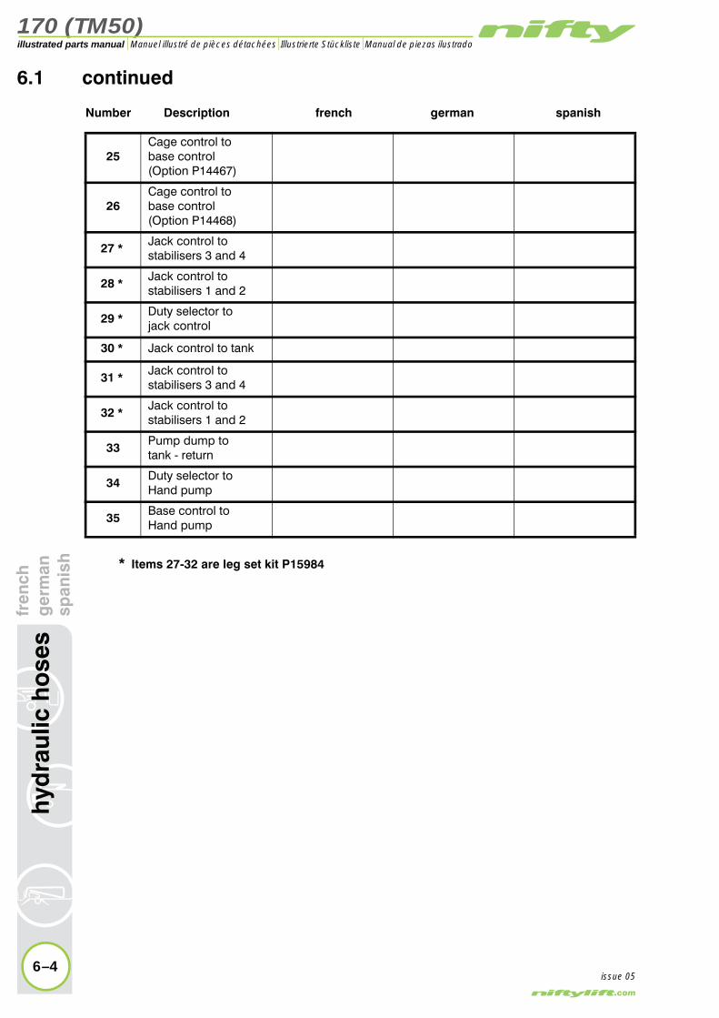
170 (TM50)illustrated parts manual Manuel illustré de pièces détachées Illustrierte Stückliste Manual de piezas ilustrado
ench
erm
anan
ish
6.1 continued
Number Description french german spanish
25Cage control to base control(Option P14467)
26Cage control to base control(Option P14468)
27 * Jack control to stabilisers 3 and 4
28 * Jack control to stabilisers 1 and 2
29 * Duty selector to jack control
30 * Jack control to tank
31 * Jack control to stabilisers 3 and 4
32 * Jack control to stabilisers 1 and 2
33Pump dump totank - return
34Duty selector toHand pump
35Base control toHand pump
* Items 27-32 are leg set kit P15984
6–4
hyd
raul
ic h
ose
sfr g sp
issue 05
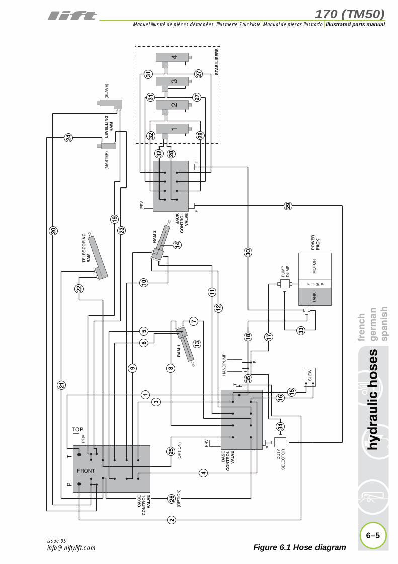
170 (TM50)
fren
chg
erm
ansp
anis
hh
ydra
ulic
ho
ses
6–5
illustrated parts manualManuel illustré de pièces détachées Illustrierte Stückliste Manual de piezas ilustrado
issue 05
���
��
���
�
����
�
�
����
����
����
��
��
� � � �
���
�����
����
��
��
����
�����
������
����
�������
��������
����
����
����
���
���������
���
����
����
����������
����
������
��
�� �
������
��
����
����
������
��
��
�
�
�
�
�
�
�
��
��
��
��
��
��
��
��
��
��
��
��
��
��
��
��
��
��
��
��
��
��
��
��
��
��
��
��
��
��
Figure 6.1 Hose diagram
