175 shielded smd power inductor - freltec · 175 : shielded smd power inductor power choke ......
TRANSCRIPT

11/18/2015 1/16© FrelTec GmbH www.freltec.comPlease read cautions and warnings and important notes at the end of this document.
FrelTec GmbH
Mathildenstr. 10A82319 Starnberg
Germany
Shielded SMD Power InductorsPower Choke

FrelTecSMD Shielded SMD Power Inductors
11/18/2015 2/16© FrelTec® GmbH www.freltec.comPlease read cautions and warnings and important notes at the end of this document.
SPECIFICATION
Part Number
175 0315D* 101* M E02**
Type Size Value Tolerance Packing
175 : ShieldedSMDPowerInductorPowerChoke
Refer to page 3 following
The value isgiven in µH and“u” indicates thedecimal point.When higher than100µH then l thelast digit is themultiplier
N: ±30%
E02 : Embossedtape and reel for2k pcs (7”reel)
which denotesthe number ofzero following
M: ±20% L0X : Embossedtape and reel for1,5k pcs (13”reel)
Example:L0Z : Embossedtape and reel for3,5k pcs (13”reel)
3U3 : 3,3 µH
220 : 22 µH
151 : 150 µH
* not allcombination ispossible
All products according to RoHS (2011/65/EU)

FrelTecSMD Shielded SMD Power Inductors
11/18/2015 3/16© FrelTec® GmbH www.freltec.comPlease read cautions and warnings and important notes at the end of this document.
Electrical Characteristics:
0315D
Part Number.Nominal
Inductance(uH)
InductanceTolerance
D.C.Resistance
±20%(0)
RatedCurrent
(mA) Self-resonant
Frequency(MHz)
Min
SaturationCurrent
Idcl
TemperatureRise Current
Idc2
0315D1UON 1,0 ±30% 36 2100 2100 100
0315D1U5N 1,5 ±30% 48 1800 1900 87
0315D2U2M 2,2 ±20% 72 1480 1600 64
0315D3U3M 3,3 ±20% 96 1210 1450 49
0315D4U7M 4,7 ±20% 136 1080 1250 40
0315D6U8M 6,8 ±20% 211 900 900 36
0315D100M 10 ±20% 0,2678 750 870 28
0315D-220M 22 ±20% 598 470 550 20
Test Equipment:Inductance: Chroma3302+1320+16502 or equivalent.DCR: Chroma16502 or equivalent.SRF: HP4291B or equivalent.
0418D
Part Number.InductanceSymbol
NominalInductance
(uH)
InductanceTolerance
D.C.Resistance
±20%(mΩ)
Rated Current(mA)
SaturationCurrent
Idcl
TemperatureRise Current
Idc2
Seif-resonant
FrequencyMin (MHz)
0418D1UON A 1,0 ±30% 27 4000 3200 90
0418D1U5N B 1,5 ±30% 37 3300 2400 75
0418D2U2M C 2,2 ±20% 42 3000 2200 60
0418D3U3M E 3,3 ±20% 55 2300 2000 45
0418D4U7M H 4,7 ±20% 70 2000 1700 35
0418D6U8M 1 6,8 ±20% 98 1600 1450 30
0418D100M K 10 ±20% 150 1300 1200 25
0418D150M M 15 ±20% 210 1100 850 18
0418D220M N 22 ±20% 290 900 720 15
0418D330M P 33 ±20% 460 700 550 12
0418D470M S 47 ±20% 650 600 440 10
0418D680M T 68 ±20% 1000 520 320 8,3
0418D101M V 100 ±20% 1450 420 280 6,5
0418D151M W 150 ±20% 2300 340 220 5,5
0418D221M X 220 ±20% 3800 275 170 4,0
Test Equipment:

FrelTecSMD Shielded SMD Power Inductors
11/18/2015 4/16© FrelTec® GmbH www.freltec.comPlease read cautions and warnings and important notes at the end of this document.
Inductance: Chroma3302+1320. or equivalent.DCR: Chroma16502 or equivalent.SRF: HP4291B or equivalent.
0540D
PART Number.Nominal
Inductance(uH)
InductanceTolerance
D.C.Resistance
±20%(0)
RatedCurrent
(mA)Saturation
CurrentIdcl
TemperatureRise Current
Idc2
Self-resonant
FrequencyMin (MHz)
0540D1U5N 1,5 ±30% 17 6400 4500 60
0540D2U2N 2,2 ±30% 22 5000 3700 42
0540D3U3N 3,3 ±30% 27 4000 3300 32
0540D4U7N 4,7 ±30% 29 3300 3100 28
0540D6U8M 6,8 ±20% 49 2800 2400 21
0540D100M 10 ±20% 56 2300 2100 18
0540D150M 15 ±20% 80 2000 1800 13
0540D220M 22 ±20% 126 1500 1400 9
0540D330M 33 ±20% 180 1300 1200 7
0540D470M 47 ±20% 310 1100 900 6
Test Equipment:Inductance: Chroma 3302+1320 or equivalent. DCR: Chroma16502 or equivalent.SRF: HP4291B or equivalent.
For all:1. Test Frequency: 100KHz,1V.2. Saturation Current Idc1: The value of current causes a 30% inductance reduction from initial
value.3. Temperature rise current Idc2: The value of current causes a 40°C temperature rise.4. Rated Current: Either Idc1 or Idc2 whichever is smaller.5. Operating Temperature Range:-25°C to +125°C (Including seif-temperature rise)6. Storage Temp. Range : -40°C to +85°C7. MSL : Level 1

FrelTecSMD Shielded SMD Power Inductors
11/18/2015 5/16© FrelTec® GmbH www.freltec.comPlease read cautions and warnings and important notes at the end of this document.
Dimensions and recommended land pattern:0315D
DIM. TOL.
L 3,0 ±0,1
W 3,0 ±0,1
H 1,5 MAX.
e 0,9 ±0.2
f 1,9 ±0.2
unit: mm
0418D
DIM. TOL.
M1 4,0 ±0,2
M2 4,0 ±0,2
M3 1,8 MAX.
M4 1,1 ±0,2
M5 2,5 ±0,2
unit: mm
0540D

FrelTecSMD Shielded SMD Power Inductors
11/18/2015 6/16© FrelTec® GmbH www.freltec.comPlease read cautions and warnings and important notes at the end of this document.
DIM. TOL.
M1 4,9 ±0,2
M2 4,9 ±0,2
M34,1 MAX.
1R5N-100M
M34,0 MAX.
150M-470M
M4 1.2 ±0,2
M5 3,3 ±0,2
unit: mm
Exposed wire tolerance limit of coating resin part an product side.Size of exposed wire occurring to coating resin is specified below.
1. Width direction (dimension a): Acceptable when a<=w/2Nonconforming when a>w/2
2. Length direction (dimension b): Dimension b is not specified.3. When total area of exposed wire occurring to each sides is not greater than 50% of coating
resin area that is acceptable.

FrelTecSMD Shielded SMD Power Inductors
11/18/2015 7/16© FrelTec® GmbH www.freltec.comPlease read cautions and warnings and important notes at the end of this document.
Core Chipping:The appearance standard of the chipping size in top side, of bottom side ferrite Core is followingdimension
L W0315D 0,6 mm Max 0,6 mm Max0418D 1,0 mm Max 1,0 mm Max0540D 1,5 mm Max 1,5 mm Max
Material list0315D, 0418D, 0540D
1. Ferrite core. Ni-Zn ferrite
2. Winding wire Polyurethane-copper wire
3. Over-coating resin. Epoxy resin, containing ferrite powder
4. Electrode External electrode (substrate) Ag
External electrode (base plating) Ni-Sn
External electrode (top surface solder coating) Sn-Ag-Cu

FrelTecSMD Shielded SMD Power Inductors
11/18/2015 8/16© FrelTec® GmbH www.freltec.comPlease read cautions and warnings and important notes at the end of this document.
Electrical Curve:0315D
0418D
0540D

FrelTecSMD Shielded SMD Power Inductors
11/18/2015 9/16© FrelTec® GmbH www.freltec.comPlease read cautions and warnings and important notes at the end of this document.
FrelTecSMD Shielded SMD Power Inductors
11/18/2015 10/16© FrelTec® GmbH www.freltec.comPlease read cautions and warnings and important notes at the end of this document.
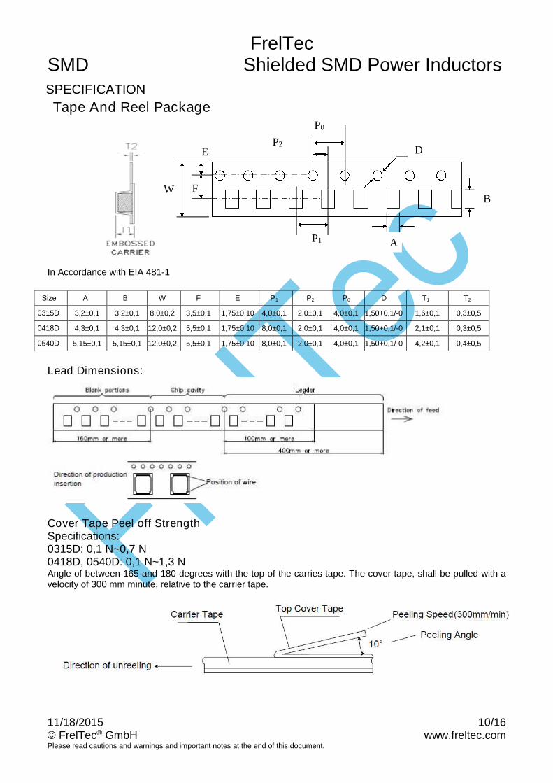
SPECIFICATION
Tape And Reel Package
In Accordance with EIA 481-1
Size A B W F E P1 P2 P0 D T1 T2
0315D 3,2±0,1 3,2±0,1 8,0±0,2 3,5±0,1 1,75±0,10 4,0±0,1 2,0±0,1 4,0±0,1 1,50+0,1/-0 1,6±0,1 0,3±0,5
0418D 4,3±0,1 4,3±0,1 12,0±0,2 5,5±0,1 1,75±0,10 8,0±0,1 2,0±0,1 4,0±0,1 1,50+0,1/-0 2,1±0,1 0,3±0,5
0540D 5,15±0,1 5,15±0,1 12,0±0,2 5,5±0,1 1,75±0,10 8,0±0,1 2,0±0,1 4,0±0,1 1,50+0,1/-0 4,2±0,1 0,4±0,5
Lead Dimensions:
Cover Tape Peel off StrengthSpecifications:0315D: 0,1 N~0,7 N0418D, 0540D: 0,1 N~1,3 NAngle of between 165 and 180 degrees with the top of the carries tape. The cover tape, shall be pulled with avelocity of 300 mm minute, relative to the carrier tape.
P1 A
D
BW
E
F
P2
P0

FrelTecSMD Shielded SMD Power Inductors
11/18/2015 11/16© FrelTec® GmbH www.freltec.comPlease read cautions and warnings and important notes at the end of this document.
Reel Type /Tape
Reel sizeQuantityper reel[pcs.]
A N C B G T
0315D 7” 2000 180±0,560+1
-013,0±0,5 2,0±0,5
10,0±1,5 15,0
0418D
13”3500
330±3 80±2 13,5±1,0 18,5 max0540D 1500
in mm

FrelTecSMD Shielded SMD Power Inductors
11/18/2015 12/16© FrelTec® GmbH www.freltec.comPlease read cautions and warnings and important notes at the end of this document.
Storage Temperature: 25±3°CHumidity < 80%RH
Characteristics
Operating temperature range: -25°C to +125°CIsat: For Inductance drop 35% from its value with current.
Irms: The value of D.C current, measured when the temperature rise is ΔT≦40°C
(Ta=25°C)
Stock periodThe performance of these products, including the solderability, is guaranteed for one yearafter production date code, provided that they remain packed as they were whendelivered and stored at a temperature of 25°C ± 3°C and a relative humidity less than80%RH
Lead Free Reflow Soldering Profile
The products may be exposed to reflow soldering process of above profile up to twotimes.

FrelTecSMD Shielded SMD Power Inductors
11/18/2015 13/16© FrelTec® GmbH www.freltec.comPlease read cautions and warnings and important notes at the end of this document.
Mechanical Performance /Environmental Test Performance Specifications:
Test Item Standard Test method
Resistance toDeflection
No damage. The test samples shall be soldered to the test boardby the reflow soldering conditions show in Reflow Profile Chart Asillustrated below, apply force in the direction of theArrow indicating until deflection of the test boardReaches to 2 mm.
Land dimension Unit: mm
Test board size :100x40x10Test board material I: glass epoxy-resinSolder cream thickness:0,1
Adhesion ofTerminal Electrode
Shall not come off PCboard
The test samples shall be soldered to the test boardBy the reflow soldering conditions shown in Reflow Profile Chart
Applied force:10 N to X and Y directionsDuration:5 s.Solder cream thickness: 0,1mm(Refer to recommended Land Pattern DimensionsDefined in "Precaution")
Body strength No damage Applied force :0315D: 30 N0540D, 0418D: 20 NDuration :10 s

FrelTecSMD Shielded SMD Power Inductors
11/18/2015 14/16© FrelTec® GmbH www.freltec.comPlease read cautions and warnings and important notes at the end of this document.
Resistance toVibration
ΔL/L: within±10% No abnormalityobserved Inappearance
The test samples shall be soldered to the test board byThe reflow soldering conditions shown in Reflow Profile Chart.Then it shall be submitted to below test conditions
Frequency range 10Hz-55Hz
Total Amplitude1,5mm (May not exceed acceleration196 m/s2)
Sweeping Method 10Hz to 55Hz to 10 Hz for 1 min.
Time For 2 hours an each X, Y, and Z axis.
Resistance toSoldering heat(Reflow)
ΔL/L:within±10%No abnormalityobserved Inappearance
The test sample shall be exposed to reflow oven at 230±5 °C for 40seconds, with peak temperature at 260±5 °C for 5 seconds, 2 times.Test board thickness: 1,0 mmTest board material: glass epoxy-resin
Solder ability At least 90% ofsurface of terminalelectrode is coveredby new solder.
The test samples shall be dipped in flux, and then Immersed in moltensolder as shown in below table. Flux: Methanol solution containingrosin 25%
Solder Temperature 245±°C
Time 5±1,0s
Immersing Speed 25 mm/s
TemperatureCharacteristics
ΔL/L:within±20%
No abnormalityobserved inappearance
Measurement of inductance shall be taken at temperatureRange within -25 °C to +85 °C.With reference to inductance value at +20°C, change Rate shall becalculated.
Thermal shock ΔL/L:within±10%
No abnormalityobserved Inappearance
The test samples shall be soldered to test boardBy the reflow soldering conditions shown in Reflow Profile Chart Thetest samples shall be placed at specified temperature for specified timeby step 1 to 4 as shown in below table in sequence.Shown in below table in sequence.The temperature cycle shall be repeated 100 cycles.Conditions of steps for 1 cycle
Step Temperature Time(min)
1 -40±3 °C 30±3
2 Room Temp 3 maximum
3 85±2 °C 30±3
4 Room Temp 3 maximum
Low Temperaturelife Test
ΔL/L:within±10%No abnormalityobserved Inappearance
The test samples shall be soldered to the test board byThe reflow soldering conditions shown in Reflow ProfileChar. After that, the test samples shall be placed at testConditions as shown in below table.
Temperature -40±2 °C
Time 500 +24/-0 h

FrelTecSMD Shielded SMD Power Inductors
11/18/2015 15/16© FrelTec® GmbH www.freltec.comPlease read cautions and warnings and important notes at the end of this document.
Loading at hightemperature life test
ΔL/L:within±10%No abnormalityobserved inappearance.
The test samples shall be soldered to the test board by thereflow soldering conditions shown in Reflow Profile Chart.The test samples shall be placed in thermostatic oven set atspecified temperature and applied the rated current continuouslyas shown in below table.
Temperature 85±2 °C
Applied currentRated current (Refer to Page 3following)
Time 500+24/-0 h
Damp heat life test ΔL/L:within±10%No abnormalityobserved inappearance.
The test samples shall be soldered to the test board by thereflow soldering conditions shown in Reflow Profile Chart.The test samples shall be placed in thermostatic oven set atspecified temperature and applied the rated current continuouslyas shown in below table.
Temperature 60±2 °C
Applied current 0-95%RH
Time 500+24/-0 h
Loading underDamp heat life
test
ΔL/L:within±10%No abnormalityobserved inappearance.
The test samples shall be soldered to the test board by thereflow soldering conditions shown in Reflow Profile Chart.The test samples shall be placed in thermostatic oven set atspecified temperature and humidity and applied the rated currentcontinuously as shown in below table.
Temperature 60±2°C
Humidity 0-95%RH
Applied currentRated current (Refer to Page3following)
Time 500+24/-0 h
FrelTecSMD Shielded SMD Power Inductors
11/18/2015 16/16© FrelTec® GmbH www.freltec.comPlease read cautions and warnings and important notes at the end of this document.
Published by FrelTec® GmbHMathildenstr. 10A; 82319 Starnberg; Germany
2015 FrelTec® GmbH. All Rights Reserved.
The following applies to all products named in this publication:1. The information describes the type of component and shall not be considered as assured characteristics.2. Terms of delivery and rights to change design reserved.3. Some parts of this publication contain statements about the suitability of our products for certain areas of application.
These statements are based on our knowledge of typical requirements that are often placed on our productsin the areas of application concerned. Nevertheless, we explicitly point out that such statements cannot beregarded as binding statements about the suitability of our products for a particular customer application. As a rule,FrelTec® is either unfamiliar with individual customer applications or less familiar with them than thecustomers themselves. For these reasons, it is always ultimately incumbent on the customer to check anddecide whether a FrelTec® product with the properties described in the product specification is suitable foruse in a particular customer application.
4. We also point out that in individual cases, a malfunction of electronic components or failure before the end of theirusual service life cannot be completely ruled out in the current state of the art, even if they are operated as specified. Incustomer applications requiring a very high level of operational safety and especially in customer applicationsin which the malfunction or failure of an electronic component could endanger human life or health (e.g. inaccident prevention or life-saving systems), it must therefore be ensured by means of suitable design of thecustomer application or other action taken by the customer (e.g. installation of protective circuitry orredundancy) that no injury or damage is sustained by third parties in the event of malfunction or failure of anelectronic component.
5. The warnings, cautions and product-specific notes must be observed.6. In order to satisfy certain technical requirements, some of the products described in this publication may contain
substances subject to restrictions in certain jurisdictions (e.g. because they are classed as “hazardous”). Usefulinformation on this will be found in our Material Data Sheets. Should you have any more detailed questions,please contact our sales offices.
7. We constantly strive to improve our products. Consequently, the products described in this publication may changefrom time to time. The same is true for the corresponding product specifications. Please check therefore towhat extent product descriptions and specifications contained in this publication are still applicable before orwhen you place an order. We also reserve the right to discontinue production and delivery of products.Consequently, we cannot guarantee that all products named in this publication will always be available.
8. Unless otherwise agreed in individual contracts, all orders are subject to the current version of the “Generalconditions for the supply of products and services of the electrical and electronics industry” published by the GermanElectrical and Electronics Industry Association (ZVEI), available at www.freltec.com.
9. As far as patents or other rights of third parties are concerned, liability is only assumed for components per se, notfor applications, processes and circuits implemented within components or assemblies.
10. The trade name FrelTec® is a trademark registered or pending in Europe and in other countries.