176 making things talk - homes.create.aau.dk
TRANSCRIPT

176 MAKING THINGS TALK

Wireless CommunicationIf you’re like most people interested in this area, you’ve been reading
through the early chapters thinking, “but what about wireless?” Perhaps
you’re so eager that you just skipped straight to this chapter. If you did,
go back and read the rest of the book! In particular, if you’re not familiar
with serial communication between computers and microcontrollers,
you’ll want to read Chapter 2 before you read this chapter. This chapter
explains the basics of wireless communication between objects. In it,
you’ll learn about two types of wireless communication, and build some
working examples.
6MAKE: PROJECTS
Alex Beim's Zygotes (www.tangibleinteraction.com) are lightweight inflatable rubber balls lit from within
by LED lights. The balls change color in reaction to pressure on their surface, and communicate with a central
computer using ZigBee radios. A network of zygotes at a concert allows the audience to have a direct effect
not only on the balls themselves, but also on the music and video projections to which they are networked.
Photo courtesy of Alex Beim.
178 MAKING THINGS TALK
Why Isn’t Everything Wireless?The advantage of wireless communication seems obvious at first: no wires! This makes
physical design much simpler for any project where the devices have to move and
talk to each other. Wearable sensor systems, digital musical instruments, and remote
control vehicles are all simplified physically by wireless communication. However, there
are some limits to wireless communication that you should consider before going wireless.
Wireless communication is never as reliable as wired communication
You have less control over the sources of interference. You can insulate and shield a wire carrying data com-munications, but you can never totally isolate a radio or infrared wireless link. There will always be some form of interference, so you must make sure that all the devices in your system know what to do if they get a garbled message, or no message at all, from their counterparts.
Wireless communication is never just one-to-one communication
The radio and infrared devices mentioned here broadcast their signals for all to hear. Sometimes that means they interfere with the communication between other devices. For example, Bluetooth, most Wi-Fi radios (802.11b, g, and n) and ZigBee (802.15.4) radios all work in the same frequency range, 2.4 gigahertz. They’re designed to not cause each other undue interference, but if you have a large number of ZigBee radios working in the same space as a busy Wi-Fi network, for example, you’ll get interference.
Wireless communication does not mean wireless powerYou still have to provide power to your devices, and if they’re moving, this means using battery power. Batteries add weight, and they don’t last forever. The failure of a battery when you’re testing a project can cause all kinds of errors that you might attribute to other causes. A classic example of this is the Mystery Radio Error. Many
radios consume extra power when they’re transmitting. This causes a slight dip in the voltage of the power source. If the radio isn’t properly decoupled with a capacitor across its power and ground leads, the voltage can dip low enough to make the radio reset itself. The radio may appear to function normally when you’re sending it serial messages, but it will never transmit, and you won’t know why. When you start to develop wireless projects, it’s good practice to make sure that you have the communi-cation working first using a regulated, plugged-in power supply, and then create a stable battery supply.
Wireless communication generates electromagnetic radiation
This is easy to forget about, but every radio you use emits electromagnetic energy. The same energy that cooks your food in a microwave sends your mp3 files across the Internet. And while there are many studies indicating that it’s safe at the low operating levels of the radios used here, why add to the general noise if you don’t have to?
Make the wired version firstThe radio and IR transceivers discussed here are replacements for the communications wires used in previous chapters. Before you decide to add wireless to any application, it’s important to make sure you’ve got the basic exchange of messages between devices working over wires first. X
The early part of this chapter covers how wireless works, and what makes it stop working, giving you some back-ground and starting places for troubleshooting. The second half of the chapter contains examples. the topic is so broad, even a survey of several different devices only
begins to cover the tip of the iceberg. For that reason, the exercises in this chapter will be less fully developed appli-cations than the previous ones. Instead, you’ll just get the basic “Hello World!” example for several different forms of wireless device. X

WIRELESS COMMUNICATION 179
Two Flavors of Wireless: Infrared and RadioThere are two common types of wireless communication in most people’s lives: infrared
light communication and radio communication. The main difference between them
from a user’s or developer’s position is their directionality.
Television remote controls typically use infrared (IR) com-munication. Unlike radio, it’s dependent on the orientation between transmitter and receiver. There must be a clear line of sight between the two. Sometimes IR can work by bouncing the beam off another surface, but it’s not as reliable. Ultimately, the receiver is an optical device, so it has to “see” the signal. Car door openers, mobile phones, garage door remote controls, and many other devices use radio. All of these work whether the transmitter and receiver are facing each other or not. They can even operate through walls, in some cases. In other words, their transmission is omnidirectional. Generally, IR is used for short-range line-of sight applications, and radio is used for everything else.
Transmitters, Receivers, and TransceiversThere are three types of devices common to both IR and RF systems: transmitters, which send a signal, but can’t receive one; receivers, which can receive a signal, but can’t send one; and transceivers, which can do both. You may wonder why everything isn’t a transceiver, as it’s the most flexible device. The answer is that it’s more complex and more expensive to make a transceiver than it is to make either of the other two. In a transceiver, you have to make sure the receiver is not receiving its transmitter’s trans-mission, or they’ll interfere with each other and not listen to any other device. When you buy a transceiver that does this for you, you pay for the convenience. For many appli-cations, it’s cheaper to just use a transmitter-receiver pair, and handle any errors by just transmitting the message many times until the receiver gets the message. That’s how TV remote controls work, for example. It makes the components much cheaper.
It’s increasingly common, especially in radio, to just make everything a transceiver, and incorporate a microcontroller to manage the transmitter-receiver juggling. All Bluetooth, ZigBee, and Wi-Fi radios work this way. However, it’s still possible to get transmitter-receiver pair radios, and they
are still considerably cheaper than their transceiver coun-terparts. The first two projects in this chapter use trans-mitter-receiver pairs.
Keep in mind the distinction between transmitter-receiver pairs and transceivers when you plan your projects, and when you shop. Start by asking yourself whether the com-munication in your project has to be two-way, or whether it can be one-way only. If it’s one-way, ask yourself what happens if the communication fails. Can the receiver operate without asking for clarification? Can the problem be solved by transmitting repeatedly until the message is received? If the answer is yes, then you might be able to use a transmitter-receiver pair and save some money.
How Infrared WorksIR communication works by pulsing an IR LED at a set data rate and receiving the pulses using an IR photodi-ode. It’s simply serial communication transmitted using infrared light. Since there are many everyday sources of IR light (the sun, incandescent light bulbs, any heat source), it’s necessary to differentiate the IR data signal from other IR energy. To do this, the serial output is sent to an oscil-lator before it’s sent to the output LED. The wave created by the oscillator, called a carrier wave, is a regular pulse that’s modulated by the pulses of the data signal. The receiver picks up all IR light, but filters out anything that’s not vibrating at the carrier frequency. Then it filters out the carrier frequency so that all that’s left is the data signal. This method allows you to transmit data using infrared light without getting interference from other IR light sources, unless they happen to be oscillating at the same frequency as your carrier wave.
The directional nature of infrared makes it more limited than radio, but cheaper than radio, and requires less power. As radios get cheaper, more power-efficient, and more robust, it’s less common to see an IR port on a computer or PDA, but it’s still both cost-effective and power-efficient for line-of-sight remote control applications.

180 MAKING THINGS TALK
Data protocols for the IR remote controls of most home electronics vary from manufacturer to manufacturer. To decode them, you need to know both the carrier frequency and the message structure. Most commercial IR remote control devices operate using a carrier wave between 38 and 40 kHz. The frequency of the carrier wave limits the rate at which you can send data on that wave, so IR transmission is usually done at a low data rate, typically between 500 and 2000 bits per second. It’s not great for high-bandwidth data transmission, but if you’re only sending the values of a few pushbuttons on a remote, it’s acceptable. Unlike the serial protocols you’ve seen so far in this book, IR protocols do not all use an 8-bit data format. For example, Sony’s Control-S protocol has three formats: a 12-bit, a 15-bit, and a 20-bit format. Philips’ RC5 format, common to many remotes, uses a 14-bit format.
If you have to send or receive remote control signals, you’ll save a lot of time by looking for a specialty IR modulator
chip to do the job, rather than trying to recreate the protocol yourself. Fortunately, there are many helpful sites on the web to explain the various protocols. Reynolds Elec-tronics (www.rentron.com) has many helpful tutorials, and sells a number of useful IR modulators and demodulators. EPanorama has a number of useful links describing many of the more common IR protocols at www.epanorama.net/links/irremote.html.
If you’re building both the transmitter and receiver, your job is fairly straightforward. You just need an oscillator through which you can pass your serial data to an infrared LED, and a receiver that listens for the carrier wave and demodulates the data signal. It’s possible to build your own IR modulator using a 555 timer IC, but there are a number of inexpensive modules you can buy to modulate or demodulate an IR signal, as shown in this next project. X
Even though you can’t see infrared light, cameras can. If you’re not sure whether your IR LED is working, one quick way to
check is to point the LED at a camera and look at the resulting image. You’ll see the LED light up. Here's a look at the IR LED in a
home remote control, viewed through a webcam attached to a personal computer. You can even see this in the LCD viewfinder
of a digital camera. If you try this with your IR LED, you may need to turn the lights down to see this effect.
Having a camera at hand is useful when troubleshooting IR projects.
Making Infrared Visible
WIRELESS COMMUNICATION 181
This example uses custom IR transmitter
and receiver ICs (integrated circuits) from
Reynolds Electronics to establish a one-
way link between transmitter and receiver.
This transmitter-receiver pair can operate
up to 19200 bits per second, much faster
than normal household remote controls.
MATERIALS
1 solderless breadboard such as Digi-Key (www.digikey.com) part number 438-1045-ND, or Jameco (www.jameco.com) part number 206011 Arduino module or other microcontroller1 USB-to-TTL serial adaptor SparkFun’s BOB-00718 from Chapter 2 will do the job (www.sparkfun.com). If you use a USB-to-RS-232 adaptor such as a Keyspan or Iogear dongle, refer to Chapter 2 for the schematics to convert RS-232 to TTL serial.1 IR transmitter IC Reynolds (www.rentron.com) part number TX-IRHS1 20MHz ceramic resonator with internal caps for use with the IR transmitter IC, from Reynolds1 infrared LED Reynolds part number TSAL7200, or any other IR LED will do the job.1 high-speed IR detector module Reynolds (www.rentron.com) part number TSOP70001 100-ohm resistor1 220-ohm resistor1 potentiometer
»
»»
»
»
»
»
»»»
In this example, you’ll connect the IR transmitter and a potentiometer to your microcontroller. The receiver will connect to your personal computer through a USB-to-serial adaptor. The microcontroller will continually send the potentiometer’s value to the receiving computer.
You could also build this project with two microcontrollers, of course, but it’s good practice to test the modules on a PC first so that can you troubleshoot the circuit and test the range of your IR transmitter and receiver. In testing, I got about 12 feet (3 meters) of range with this system.
There are two circuits for this project: the transmitter, which is connected to a microcontroller, and the receiver, which is connected to your computer via a USB-to-serial adaptor.
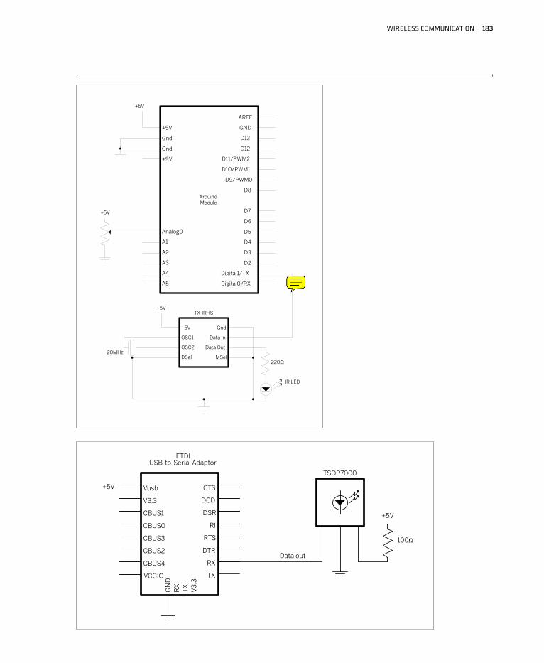
The transmitter’s connections:1. Voltage: to 5V2. Oscillator 1: to ceramic resonator pin 13. Oscillator 2: to ceramic resonator pin 34. Duty cycle select: to ground. This sets the duty cycle of
the carrier wave.5. Data inversion select: to ground. This setting specifies
whether the transmitter sends data as true (logic 0 = 0V, logic 1 = 5V), or inverted (logic 0 = 5V, logic 1 = 0V).
6. Data out: sends data out to IR LED7. Data in: to microcontroller TX8. Ground: to ground
The receiver’s connections:1. Data out: to the USB-to-serial adaptor’s receive
(RX) line 2. Ground: to ground3. Voltage: to 5V power through a 100-ohm resistor
Figures 6-1 and 6-2 show the transmitter and receiver.
Infrared Transmitter-Receiver Pair
Project 8
182 MAKING THINGS TALK
/*
IR transmit example
Language: Wiring/Arduino
*/
void setup()
// open the serial port at 19200 bps:
Serial.begin(19200);
void loop()
// read the analog input:
int analogValue = analogRead(0);
// send the value out via the transmitter:
Serial.println(analogValue, DEC);
// delay 10ms to allow the analog-to-digital receiver to settle:
delay(10);
Once you’ve got the circuit connected, transmission is
very straightforward. Here’s a program that transmits the value of a potenti-ometer:
Once you’ve got this code running on your microcontroller, connect the IR receiver circuit to your computer. Then open your serial terminal program and connect to the circuit at 19200 bits per second. You should see the value of the potentiometer printed in the serial terminal window like so:
127
128
128
129
130
129
NOTE: As you can see, serial communication over infrared isn’t that different than
serial communication over a wire. You can send data in only one direction, so you can’t
use a handshaking protocol, and you’re limited to the data rate of your transmitter-
receiver pair. Otherwise, you won’t have to make any major code changes to use IR.
D
C
B
A
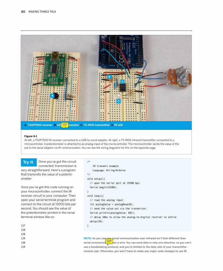
A. TSOP7000 receiver B. 16MHz resonator C. TX-IRHS transmitter D. IR LED
Try It
Figure 6-1
At left, a TSOP7000 IR receiver connected to a USB-to-serial adaptor. At right, a TX-IRHS infrared transmitter connected to a
microcontroller. A potentiometer is attached to an analog input of the microcontroller. The microcontroller sends the value of the
pot to the serial adaptor via IR communication. You can see the wiring diagrams for this on the opposite page.
WIRELESS COMMUNICATION 183
Ω

184 MAKING THINGS TALK
How Radio WorksRadio relies on the electrical property called induction. Any time you vary the electrical current in a wire, you generate a corresponding magnetic field that emanates from the wire. This changing magnetic field induces an electrical current in any other wires in the field. The frequency of the magnetic field is the same as the frequency of the current in the original wire. This means that if you want to send a signal without a wire, you can generate a changing current in one wire at a given frequency and attach a circuit to the second wire to detect current changes at that frequency. That’s how radio works.
The distance that you can transmit a radio signal depends on the signal strength, the sensitivity of the receiver, the nature of the antennas, and any obstacles that block the signal. The stronger the original current and the more sensitive the receiver, the farther apart the sender and receiver can be. The two wires act as antennas. Any conductor can be an antenna, but some work better than others. The length and shape of the antenna and the frequency of the signal all affect transmission. Antenna design is a whole field of study on its own, so I can’t do it justice here, but a rough rule of thumb for a straight wire antenna is as follows:
Antenna length5,616 in. / frequency in MHz
Antenna length14,266.06 cm. / frequency MHz
For more information, consult the technical specifications for the specific radios you’re using. Instructions on making a good antenna are common in a radio’s documentation.
Radio Transmission: Digital and AnalogAs with everything else in the microcontroller world, it’s important to distinguish between digital and analog radio transmission. Analog radios simply take an analog elec-trical signal such as an audio signal, and superimpose it on the radio frequency in order to transmit it. The radio frequency acts as a carrier wave, carrying the audio signal. Digital radios superimpose digital signals on the carrier wave, so there must be a digital device on either end to encode or decode those signals. In other words, digital radios are basically modems, converting digital data to radio signals, and radio signals back into digital data.
Radio InterferenceThough radio is omnidirectional, it can be blocked by obstacles, particularly metal ones. A large metal sheet, for example, will reflect a radio signal rather than allowing it to pass through. This principle is used not only in designing antennas, but also in designing shields. If you’ve ever cut open a computer cable and encountered a thin piece of foil wrapped around the inside wires, you’ve encountered a shield. Shields are used to prevent random radio signals from interfering with the data being transmitted down a wire. A shield doesn’t have to be a solid sheet of metal, though. A mesh of conductive metal will block a radio signal as well, if the grid of the mesh is small enough. The effectiveness of a given mesh depends on the frequency it’s designed to block. In fact, it’s possible to block radio signals from a whole space by surrounding the space with an appropriate shield and grounding the shield. You’ll hear this referred to as making a Faraday cage. A Faraday cage is just an enclosure that’s shielded to be radio-free. The effect is named after the physicist Michael Faraday, who first demonstrated and documented it.
Sometimes radio transmission is blocked by unintentional shields. If you’re having trouble getting radio signals through, look for metal that might be shielding the signal. Transmitting from inside a car can sometimes be tricky because the car body acts as a Faraday cage. Putting the antenna on the outside of the car improves reception. This is true for just about every radio housing.
All kinds of electrical devices emit radio waves as side effects of their operation. Any alternating current can generate a radio signal, even the AC that powers your home or office. This is why you get a hum when you lay speaker wires in parallel with a power cord. The AC signal is inducing a current in the speaker wires, and the speakers are reproducing the changes in current as sound. Likewise, it’s why you may have trouble operating a wireless data network near a microwave oven. Wi-Fi operates at frequencies in the gigahertz range. That range is commonly called the microwave range, because the wavelength of those signals is only a few micrometers long. Microwave ovens use those same frequencies, trans-mitted at very high power, to cook food. Some of that energy leaks from the oven at low power, which is why you get all kinds of radio noise in the gigahertz range around a microwave.
WIRELESS COMMUNICATION 185
Motors and generators are especially insidious sources of radio noise. A motor also operates by induction; specifi-cally, by spinning a pair of magnets around a shaft in the center of a coil of wire. By putting a current in the wire, you generate a magnetic field, and that attracts or repulses the magnets, causing them to spin. Likewise, by using mechanical force to spin the magnets, you generate a current in the wire. So a motor or a generator is essentially a little radio, generating noise at whatever frequency it’s rotating.
Because there are so many sources of radio noise due to the ubiquitous use of alternating currents, there are many ways for a radio signal to be interfered with. It’s important to keep these possible sources of noise in mind when you begin to work with radio devices. Knowledge of common interference sources, and knowing how to shield against them, is a valuable tool in radio troubleshooting.
Multiplexing and ProtocolsWhen you’re transmitting data via radio, anyone with a compatible receiver can receive your signal. There’s no wire to contain the signal, so if two transmitters are sending at the same time, they will interfere with each other. This is the biggest weakness of radio: a given receiver has no way to know who sent the signal it’s receiving. In contrast, consider a wired serial connection: you can be reasonably sure when you receive an electri-cal pulse on a serial cable that it came from the device on the other end of the wire. You have no such guarantee with radio. It’s as if you were blindfolded at a cocktail party and everyone else there had the same voice. The only way you’d have of knowing who was saying what is if everyone were polite about not interrupting each other, clear about beginning and ending their sentences, and identifying themselves when they speak. In other words, it’s all about protocols.
The first thing everyone at that cocktail party would have to do is to agree on who speaks when. That way they could all share your attention by dividing up the time they get. Sharing in radio communication is called multiplexing, and this form of sharing is called time division multiplexing. Each transmitter gets a given time slot in which to transmit.
Of course, it depends on all the transmitters being in synch. When they’re not, time division multiplexing can still work reasonably well if all the transmitters speak
much less than they listen (remember the first rule of love and networking from Chapter 1: listen more than you speak). If a given transmitter is transmitting for only a few milliseconds in each second, and if there’s a limited number of transmitters, the chance that any two messages will overlap, or collide, is relatively low. This guideline, combined with a request for clarification from the receiver (rule number three), can ensure reasonably good RF communication.
Back to the cocktail party. If every speaker spoke in a different tone, you could distinguish them by their tones. In radio terms, this is called frequency division multiplex-ing. It means that the receiver has to be able to receive on several frequencies simultaneously. But if there’s a coordi-nator handing out frequencies to each pair of transmitters and receivers, it’s reasonably effective.
Various combinations of time and frequency division multiplexing are used in every digital radio transmission system. The good news is that most of the time you never have to think about it, because it’s handled for you by many of the radios on the market today, including the ones you’ll see shortly.
Multiplexing helps transmission by arranging for transmit-ters to take turns and to distinguish themselves based on frequency, but it doesn’t concern itself with the content of what’s being said. This is where data protocols come in. Just as you saw how data protocols made wired network-ing possible, you’ll see them come into play here as well. It’s common to use a data protocol on top of using multi-plexing methods, to make sure that the message is clear. For example, Bluetooth, ZigBee, and Wi-Fi are nothing more than data networking protocols layered on top of a radio signal. All three of them could just as easily be imple-mented on a wired network (and in a sense, Wi-Fi is: it uses the same TCP/IP layer that Ethernet uses). The principles of these protocols are no different than those of wired networks, which makes it possible to understand wireless data transmission even if you’re not a radio engineer. Remember the principles and troubleshooting methods you used when dealing with wired networks, because you’ll use them again in wireless projects. The methods mentioned here are just new tools in your troubleshooting toolkit. You’ll need them in the projects that follow. X
186 MAKING THINGS TALK
MATERIALS
1 solderless breadboard such as Digi-Key part number 438-1045-ND or Jameco part number 206011 Arduino module or other microcontroller1 USB-to-TTL serial adaptor SparkFun’s BOB-00718 from Chapter 2 will do the job. If you use a USB-to-RS-232 adaptor such as a Keyspan or Iogear dongle, refer to Chapter 2 for the schematics to convert RS-232 to 5V TTL serial.1 RF transmitter-receiver pair Available from SparkFun as part number WRL-07813, but similar models from the other retailers will work as well.1 10KΩ potentiometer2 0.1µF capacitors
»
»»
»
»»
When your project is simple enough to
work with one-way communication, but
you need the omnidirectionality that
radio affords, RF transmitter-receiver
pairs are the way to go. There are several
models on the market, from companies
like Abacom (www.abacomdirect.com),
Reynolds (www.rentron.com), Glolab
(www.glolab.com), and others. Most of
them are very simple to interface with a
microcontroller, requiring nothing more
than power, ground, and a connection to
the serial I/O lines of the controller. Many
of them even come with built-in antennas.
This example uses a TX/RX pair made by
Laipac, sold by SparkFun. The transmit-
ter and receiver both connect directly to a
microcontroller’s serial lines as described
above, and can operate at voltages in the
3.3V to 5V range.
In this example, you’ll connect the RF transmitter and a potentiometer to your microcontroller. The receiver will connect to your personal computer through a USB-to-serial adaptor. The microcontroller will continually send the potentiometer’s value to the receiving computer.
There are two circuits for this project: the transmitter, which is connected to a microcontroller, and the receiver, which is connected to your computer via a USB-to-serial adaptor. The connections are as follows:
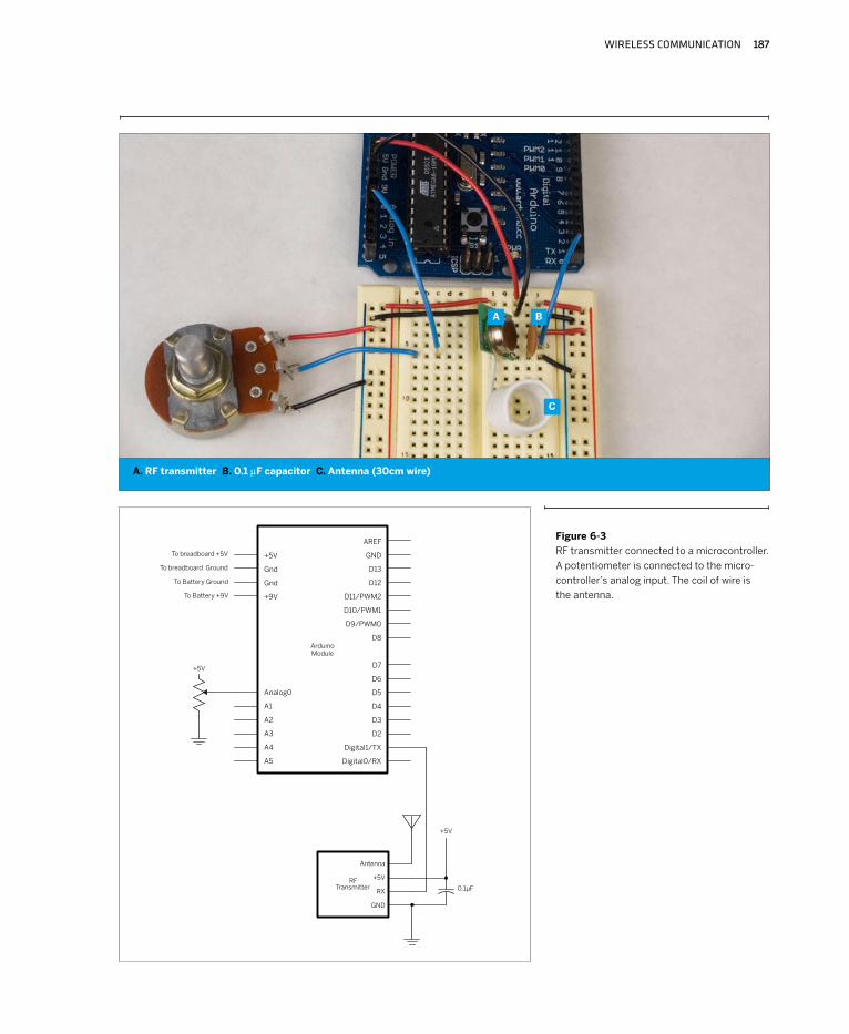
Transmitter1. Ground2. Data in: to microcontroller transmit pin3. Voltage: to 5V4. Antenna: to a 30cm piece of wire, acting as an antenna
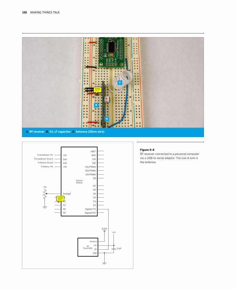
Receiver1. Ground2. Data out: to USB-to-serial RX pin3. Linear out: not connected4. Voltage: to +5V5. Voltage: to +5V. Be sure to put a 0.1µF capacitor across
voltage and ground to decouple the radio’s power supply.
6. Ground7. Ground8. Antenna: to a 30cm piece of wire, which acts as an
antenna.
Figure 6-3 shows the transmitter, and Figure 6-4 shows the receiver.
Radio Transmitter-Receiver Pair
Project 9
WIRELESS COMMUNICATION 187
Figure 6-3
RF transmitter connected to a microcontroller.
A potentiometer is connected to the micro-
controller’s analog input. The coil of wire is
the antenna.
A
A. RF transmitter B. 0.1 µF capacitor C. Antenna (30cm wire)
B
C
188 MAKING THINGS TALK
Figure 6-4
RF receiver connected to a personal computer
via a USB-to-serial adaptor. The coil of wire is
the antenna.
C
A. RF receiver B. 0.1 µF capactior C. Antenna (30cm wire)
B
A
WIRELESS COMMUNICATION 189
When you’ve got the microcontroller pro-grammed, open the serial port that the receiver
is connected to using your serial terminal program, at 2400 bits per second (thus far you’ve operated at 9600 or 19200 bps. For this example, just set your serial terminal program to communicate at 2400 bps instead of 9600). You might see a string of garbage characters. That’s because the transmitter started sending before the receiver was activated. Reset the microcontroller while the serial port is open. After a few seconds, it should start sending again, and you should see a string of numbers representing the potentiometer’s value, like this:
127
128
128
129
130
129
You may also get garbage characters on the screen, even when the transmitter is turned off. This is because the receiver’s picking up random noise in its frequency range. This can be generated by a wide range of sources. All elec-trical devices emit some RF waves, so if your receiver is
sitting beside an LCD or CRT display, for example, it could be picking up noise from that. In the absence of a signal from the transmitter, the receiver will display anything it gets. This is one of the downsides of working with simple transmitter-receiver pairs like this: you need to filter out the garbage in your program. More advanced transceivers like the ones in the next example will do some or all of that filtering for you.
One simple way to filter out the noise is to limit your transmission to a definite range of values. If you transmit only in ASCII-encoded strings separated by commas, linefeeds, or return characters, you can ignore any bytes received that don’t fit within those values. Furthermore, if you send the data in a particular format every time, your receiving program can ignore any strings it receives that don’t match the pattern. The bytes you’re receiving from the example program are always in the ASCII numeral range (“0” through “9”, or ASCII values 48 through 57), or a linefeed and carriage return (ASCII 10 and 13). In addition, the strings are never more than four digits long, because the analog input value never exceeds 1023. So you can test whether the bytes match the accepted values, and whether the string is of the appropriate length.
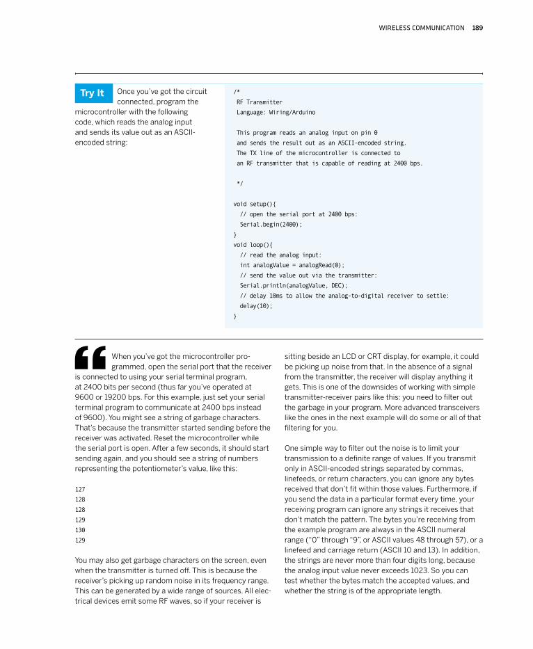
/*
RF Transmitter
Language: Wiring/Arduino
This program reads an analog input on pin 0
and sends the result out as an ASCII-encoded string.
The TX line of the microcontroller is connected to
an RF transmitter that is capable of reading at 2400 bps.
*/
void setup()
// open the serial port at 2400 bps:
Serial.begin(2400);
void loop()
// read the analog input:
int analogValue = analogRead(0);
// send the value out via the transmitter:
Serial.println(analogValue, DEC);
// delay 10ms to allow the analog-to-digital receiver to settle:
delay(10);
Once you’ve got the circuit connected, program the
microcontroller with the following code, which reads the analog input and sends its value out as an ASCII-encoded string:
Try It
190 MAKING THINGS TALK
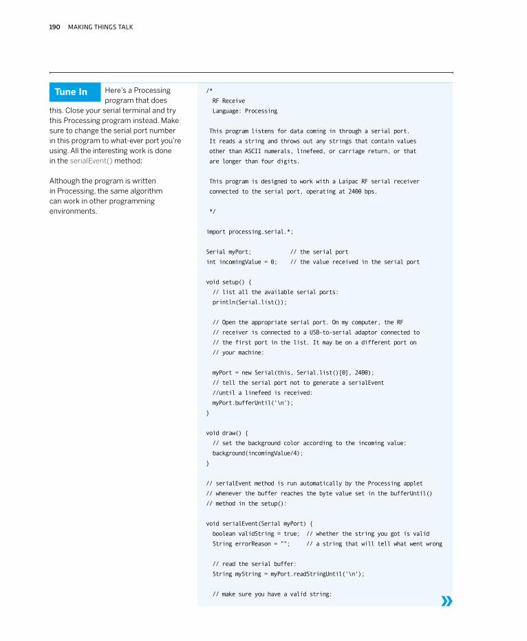
/*
RF Receive
Language: Processing
This program listens for data coming in through a serial port.
It reads a string and throws out any strings that contain values
other than ASCII numerals, linefeed, or carriage return, or that
are longer than four digits.
This program is designed to work with a Laipac RF serial receiver
connected to the serial port, operating at 2400 bps.
*/
import processing.serial.*;
Serial myPort; // the serial port
int incomingValue = 0; // the value received in the serial port
void setup()
// list all the available serial ports:
println(Serial.list());
// Open the appropriate serial port. On my computer, the RF
// receiver is connected to a USB-to-serial adaptor connected to
// the first port in the list. It may be on a different port on
// your machine:
myPort = new Serial(this, Serial.list()[0], 2400);
// tell the serial port not to generate a serialEvent
//until a linefeed is received:
myPort.bufferUntil('\n');
void draw()
// set the background color according to the incoming value:
background(incomingValue/4);
// serialEvent method is run automatically by the Processing applet
// whenever the buffer reaches the byte value set in the bufferUntil()
// method in the setup():
void serialEvent(Serial myPort)
boolean validString = true; // whether the string you got is valid
String errorReason = ""; // a string that will tell what went wrong
// read the serial buffer:
String myString = myPort.readStringUntil('\n');
// make sure you have a valid string:
Here’s a Processing program that does
this. Close your serial terminal and try this Processing program instead. Make sure to change the serial port number in this program to what-ever port you’re using. All the interesting work is done in the serialEvent() method:
Although the program is written in Processing, the same algorithm can work in other programming environments.
»
Tune In
WIRELESS COMMUNICATION 191
Now that you’ve seen the basics of sending serial data in one direction over a
radio link, the next example will demonstrate how to send it in two directions,
using a pair of RF transceivers. Even though the transceivers in the next example
incorporate their own error checking, you might want to keep this checking method
in mind, in case you need it.
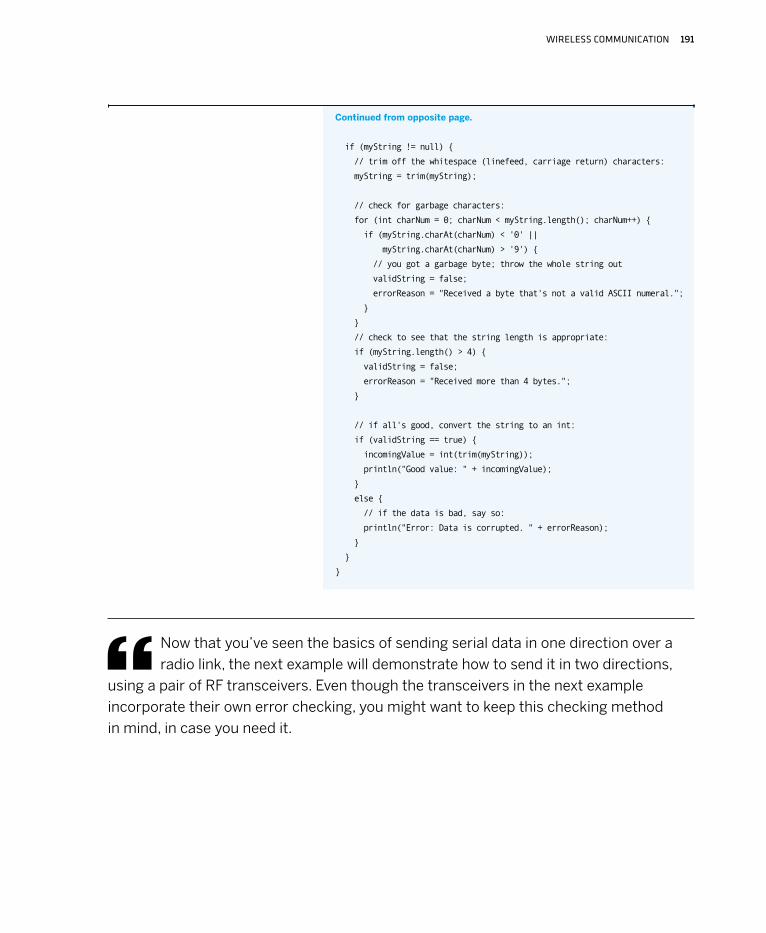
if (myString != null)
// trim off the whitespace (linefeed, carriage return) characters:
myString = trim(myString);
// check for garbage characters:
for (int charNum = 0; charNum < myString.length(); charNum++)
if (myString.charAt(charNum) < '0' ||
myString.charAt(charNum) > '9')
// you got a garbage byte; throw the whole string out
validString = false;
errorReason = "Received a byte that's not a valid ASCII numeral.";
// check to see that the string length is appropriate:
if (myString.length() > 4)
validString = false;
errorReason = "Received more than 4 bytes.";
// if all's good, convert the string to an int:
if (validString == true)
incomingValue = int(trim(myString));
println("Good value: " + incomingValue);
else
// if the data is bad, say so:
println("Error: Data is corrupted. " + errorReason);
Continued from opposite page.
192 MAKING THINGS TALK
Radio TransceiversIn many cases, one-way communication isn’t enough. For example, you might have
noticed in the previous example that sometimes the message doesn’t get through,
even when you’ve got the circuitry and the code fully working. In that case, you might
want the PC to be able to query the microcontroller occasionally to see the state of
the inputs. Or perhaps you’re making an application in which there’s input and output
on both sides. In that case, transceivers are essential.
There are many different kinds of data transceivers on the market. Some connect directly to the serial I/O of the microcontroller and send the data as is. Some, like the Bluetooth module you saw in Chapter 2, add an additional protocol layer on top of the data communication, so you have to be able to implement that protocol on both sender and receiver. The cost of transceivers varies widely.
Until recently, most digital radio transceivers on the market implemented only the most basic serial com-munications protocol. For example, the RTF-DATA-SAW transceivers from Abacom do a good job of sending and receiving serial information. They connect directly to the serial transmit and receive pins of your microcontroller. Any serial data that you send out the transmit line goes directly out as a radio signal. Any pulses received by the transceiver are sent into your microcontroller’s receive line. The benefit is that you don’t have to learn any serial protocol — you can send data in any form you want. The cost is that you have to manage the whole conversation yourself. If the receiving transceiver misses a bit of data, you’ll get a garbled message, just like you did with the transmitter-receiver pair in the preceding project. Fur-thermore, any radio device in the same frequency range can affect the quality of your reception. As long as you’re working with just two radios and no interference, trans-ceivers like the RTF-DATA-SAW do a fine job. There are other companies on the market who sell similar transceiv-ers, including Linx Technologies (www.linxtechnologies.com). Low Power Radio Solutions (www.lprs.co.uk).
There are an increasing number of cheap transceivers on the market that implement networking protocols, handling the conversation management for you. The Bluetooth modem in Chapter 2 ignored signals from other radios that it wasn’t associated with, and took care of error checking for you. The XBee radios you’ll use in the
next project will do the same, and much more, as you’ll see in Chapter 7. These particular transceivers are in the same general price range as the plain serial transceivers mentioned earlier. They require you to learn a bit more in terms of networking protocols, but the benefits you gain make them well worth that minor cost.
There’s one other difference between the serial trans-ceivers and the networked ones: the networked modules tend to operate at much higher speeds, both in terms of transmission frequency and serial data rate. For example, the Abacom modules mentioned previously operate at 315 MHz and a maximum serial data rate of 9600 bits per second. The XBee modules in the following project operate at 2.4Ghz and up to 115,200 bits per second. Hence, the XBee radios can send a message at nearly 100 times the speed. Even if you’re sending only a few bytes per second, this means that your transceiver can spend more time listening and less time speaking, thus reducing the chance that it’ll miss a given message from another transceiver. X
WIRELESS COMMUNICATION 193
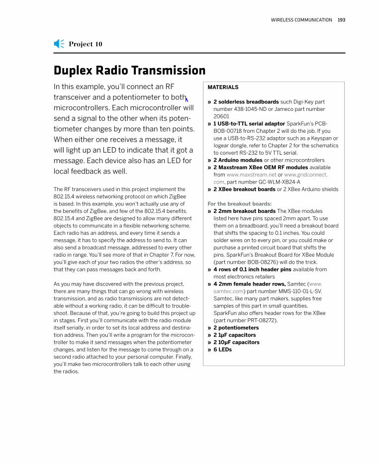
In this example, you’ll connect an RF
transceiver and a potentiometer to both
microcontrollers. Each microcontroller will
send a signal to the other when its poten-
tiometer changes by more than ten points.
When either one receives a message, it
will light up an LED to indicate that it got a
message. Each device also has an LED for
local feedback as well.
MATERIALS
2 solderless breadboards such Digi-Key part number 438-1045-ND or Jameco part number 206011 USB-to-TTL serial adaptor SparkFun’s PCB-BOB-00718 from Chapter 2 will do the job. If you use a USB-to-RS-232 adaptor such as a Keyspan or Iogear dongle, refer to Chapter 2 for the schematics to convert RS-232 to 5V TTL serial.2 Arduino modules or other microcontrollers2 Maxstream XBee OEM RF modules available from www.maxstream.net or www.gridconnect.com, part number GC-WLM-XB24-A2 XBee breakout boards or 2 XBee Arduino shields
For the breakout boards:2 2mm breakout boards The XBee modules listed here have pins spaced 2mm apart. To use them on a breadboard, you’ll need a breakout board that shifts the spacing to 0.1 inches. You could solder wires on to every pin, or you could make or purchase a printed circuit board that shifts the pins. SparkFun’s Breakout Board for XBee Module (part number BOB-08276) will do the trick. 4 rows of 0.1 inch header pins available from most electronics retailers4 2mm female header rows, Samtec (www.samtec.com) part number MMS-110-01-L-SV. Samtec, like many part makers, supplies free samples of this part in small quantities. SparkFun also offers header rows for the XBee (part number PRT-08272).2 potentiometers2 1µF capacitors2 10µF capacitors6 LEDs
»
»
»»
»
»
»
»
»»»»
Duplex Radio Transmission
The RF transceivers used in this project implement the 802.15.4 wireless networking protocol on which ZigBee is based. In this example, you won’t actually use any of the benefits of ZigBee, and few of the 802.15.4 benefits. 802.15.4 and ZigBee are designed to allow many different objects to communicate in a flexible networking scheme. Each radio has an address, and every time it sends a message, it has to specify the address to send to. It can also send a broadcast message, addressed to every other radio in range. You’ll see more of that in Chapter 7. For now, you’ll give each of your two radios the other’s address, so that they can pass messages back and forth.
As you may have discovered with the previous project, there are many things that can go wrong with wireless transmission, and as radio transmissions are not detect-able without a working radio, it can be difficult to trouble-shoot. Because of that, you’re going to build this project up in stages. First you’ll communicate with the radio module itself serially, in order to set its local address and destina-tion address. Then you’ll write a program for the microcon-troller to make it send messages when the potentiometer changes, and listen for the message to come through on a second radio attached to your personal computer. Finally, you’ll make two microcontrollers talk to each other using the radios.
Project 10
194 MAKING THINGS TALK
Figure 6-5 shows an XBee module connected to a USB-to-serial adaptor. The USB adaptor draws power from the USB bus, and the radio draws power from the adaptor via its 3.3V voltage output.
Once you’ve got the XBee module’s circuit built and powered, the LED on pin 13 should stay on steadily, and the LED on pin 15 will blink. The former is lit when the module is active (LED on), and the latter blinks whether the radio is associated with another radio (LED blinking) or not (LED on steadily). Make sure that your circuit is connected to your computer (USB port or serial port) and open the port in your favorite serial terminal program:
+++
Don’t type the return key or any other key for at least one second afterward. It should respond like so:
OK
This step should look familiar to you from the Bluetooth modem you saw in Chapter 2. The XBee is using an AT-style command set like the Bluetooth modem did, and the +++ puts it into command mode. The one-second pause after this string is called the guard time. If you do nothing, the module will drop out of command mode after ten seconds, so if you’re reading this while typing, you may need to enter another +++ string before the next stage.
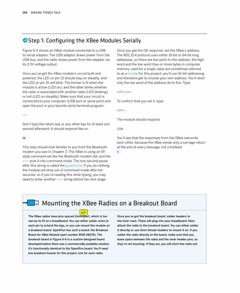
The XBee radios have pins spaced 2mm apart, which is too
narrow to fit on a breadboard. You can either solder wires to
each pin to extend the legs, or you can mount the module on
a breakout board. SparkFun has such a board: the Breakout
Board for XBee Module (part number BOB-08276). The
breakout board in Figure 6-6 is a custom-designed board
developed before there was a commercially available solution.
It’s functionally identical to the SparkFun board. You’ll need
two breakout boards for this project, one for each radio.
Once you’ve got the breakout board, solder headers to
the inner rows. These will plug into your breadboard. Next,
attach the radio to the breakout board. You can either solder
it directly or use 2mm female headers to mount it on. If you
solder the radio directly to the board, make sure that you
leave space between the radio and the inner header pins, so
they’re not touching. If they are, you will short the radio out.
Mounting the XBee Radios on a Breakout Board
Once you get the OK response, set the XBee’s address. The 802.15.4 protocol uses either 16-bit or 64-bit long addresses, so there are two parts to the address, the high word and the low word (two or more bytes in computer memory used for a single value are sometimes referred to as a word). For this project, you’ll use 16-bit addressing and therefore get to choose your own address. You’ll need only the low word of the address do to this. Type:
ATMY1234\r
To confirm that you set it, type:
ATMY\r
The module should respond:
1234
You’ll see that the responses from the XBee overwrite each other, because the XBee sends only a carriage return at the end of every message, not a linefeed. X
•Step 1: Configuring the XBee Modules Serially

WIRELESS COMMUNICATION 195
Figure 6-5
XBee radio attached to an FTDI USB-to-serial adaptor. The second photo
shows the wiring underneath the XBee board. Note that the LEDs attached
to the XBee have no resistors in series with them. The current out of the
XBee’s output pins is low enough to not burn up the LEDs.
196 MAKING THINGS TALK
There is an alternative to the breadboard circuit shown in
Figure 6-5 for Arduino users. Libelium (www.libelium.com) and
PCB Europe (pcb-europe.com) have teamed up to make an
XBee shield for the Arduino module. The shield comes with
an XBee radio, and connects to the Arduino’s TX and RX
pins. To connect the radio to the Arduino, set the XBEE/USB
jumpers to the left, as shown in Figure 6-7. When you’re
programming the Arduino, you might want to remove the
jumpers, so that the radio’s serial communications don’t
interfere with the program upload.
You can also use your Arduino board as a USB-to-serial
converter to configure the XBee radio on the shield. To
do this, unplug your Arduino from its power source, then
remove the microcontroller chip, as shown in Figure 6-8.
Be careful not to bend the pins, so that you can put it back
when you are done. Pay attention to the orientation of the
microcontroller as well, as you have to put it back the same
way. Once you’ve removed the chip, set the shield’s XBEE/
USB jumpers to the right, as shown in Figure 6-9, and put
the shield on the board. Open a serial terminal connection
to the Arduino board’s serial port, and send commands as
shown in “Step 1: Configuring the XBee Modules Serially.”
Once you’ve configured the radio, unplug the Arduino board,
replace the microcontroller chip, set the XBEE/USB jumpers
to the left, put the shield back on, and you’re all set to
program the Arduino to talk to the XBee radio.
These shields may change their form by the time this book
is published, but even in their initial form, they are a conve-
nient way to combine Arduinos and XBees.
Arduino XBee Shield
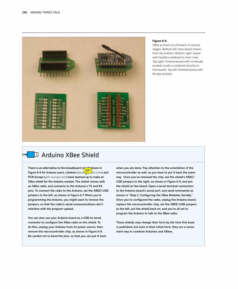
Figure 6-6
XBee printed circuit board, in various
stages. Bottom left: bare board shown
from the bottom. Bottom right: board
with headers soldered to inner rows.
Top right: finished board with no female
sockets (radio is soldered directly to
the board). Top left: finished board with
female sockets.
WIRELESS COMMUNICATION 197
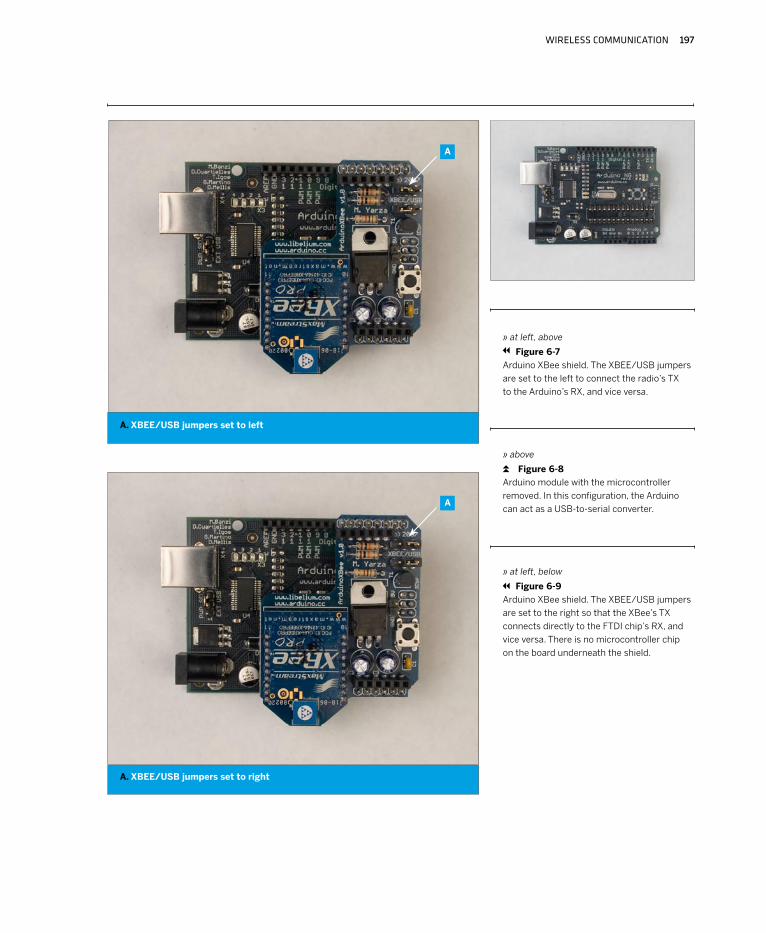
A
A. XBEE/USB jumpers set to left
A. XBEE/USB jumpers set to right
» at left, above
Figure 6-7
Arduino XBee shield. The XBEE/USB jumpers
are set to the left to connect the radio’s TX
to the Arduino’s RX, and vice versa.
» above
Figure 6-8
Arduino module with the microcontroller
removed. In this configuration, the Arduino
can act as a USB-to-serial converter.
» at left, below
Figure 6-9
Arduino XBee shield. The XBEE/USB jumpers
are set to the right so that the XBee’s TX
connects directly to the FTDI chip’s RX, and
vice versa. There is no microcontroller chip
on the board underneath the shield.
A
198 MAKING THINGS TALK
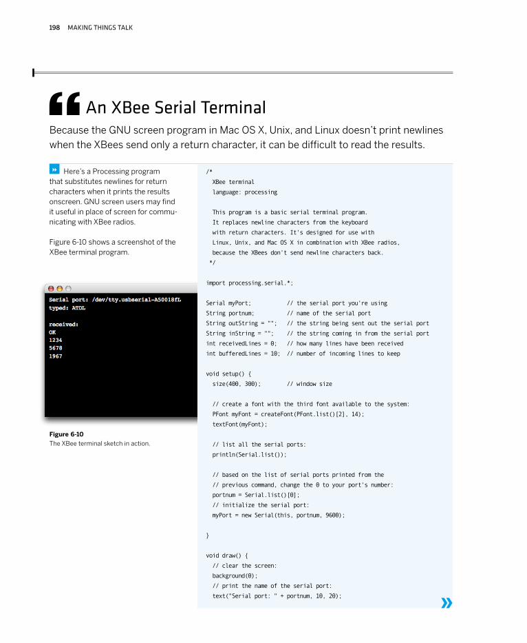
An XBee Serial TerminalBecause the GNU screen program in Mac OS X, Unix, and Linux doesn’t print newlines
when the XBees send only a return character, it can be difficult to read the results.
/*
XBee terminal
language: processing
This program is a basic serial terminal program.
It replaces newline characters from the keyboard
with return characters. It's designed for use with
Linux, Unix, and Mac OS X in combination with XBee radios,
because the XBees don't send newline characters back.
*/
import processing.serial.*;
Serial myPort; // the serial port you're using
String portnum; // name of the serial port
String outString = ""; // the string being sent out the serial port
String inString = ""; // the string coming in from the serial port
int receivedLines = 0; // how many lines have been received
int bufferedLines = 10; // number of incoming lines to keep
void setup()
size(400, 300); // window size
// create a font with the third font available to the system:
PFont myFont = createFont(PFont.list()[2], 14);
textFont(myFont);
// list all the serial ports:
println(Serial.list());
// based on the list of serial ports printed from the
// previous command, change the 0 to your port's number:
portnum = Serial.list()[0];
// initialize the serial port:
myPort = new Serial(this, portnum, 9600);
void draw()
// clear the screen:
background(0);
// print the name of the serial port:
text("Serial port: " + portnum, 10, 20);
Here’s a Processing program that substitutes newlines for return characters when it prints the results onscreen. GNU screen users may find it useful in place of screen for commu-nicating with XBee radios.
Figure 6-10 shows a screenshot of the XBee terminal program.
8
»
Figure 6-10
The XBee terminal sketch in action.
WIRELESS COMMUNICATION 199
// Print out what you get:
text("typed: " + outString, 10, 40);
text("received:\n" + inString, 10, 80);
// this method responds to key presses when the
// program window is active:
void keyPressed()
switch (key)
// In OS X, if the user types return, a linefeed is returned. But
// to communicate with the XBee, you want a carriage return:
case '\n':
myPort.write(outString + "\r");
outString = "";
break;
case 8: // backspace
// delete the last character in the string:
outString = outString.substring(0, outString.length() -1);
break;
case '+': // we have to send the + signs even without a return:
myPort.write(key);
// add the key to the end of the string:
outString += key;
break;
case 65535: // if the user types the shift key, don't type anything:
break;
// if any other key is typed, add it to outString:
default:
// add the key to the end of the string:
outString += key;
break;
// this method runs when bytes show up in the serial port:
void serialEvent(Serial myPort)
// read the next byte from the serial port:
int inByte = myPort.read();
// add it to inString:
inString += char(inByte);
if (inByte == '\r')
// if the byte is a carriage return, print
// a newline and carriage return:
inString += '\n';
// count the number of newlines:
receivedLines++;
// if there are more than 10 lines, delete the first one:
if (receivedLines > bufferedLines)
deleteFirstLine();
Continued from opposite page.
»

200 MAKING THINGS TALK
Once you’ve configured one of your radios, quit the Processing sketch (or disconnect your serial terminal program) and unplug the board from your computer. Next, remove the XBee from the circuit, insert the second one, and configure it using the same procedure. Don’t set a radio’s destination address to the same value of its source address, or it will only talk to itself! You can use any 16-bit address for your radios. Here’s a typical configuration for two radios that will talk to each other (don’t forget to add the ,WR to the last command):
You can combine commands on the same line by separat-ing them with commas. For example, to get both words of a module’s source address, type this:
ATDL, DH\r
The module will respond with both words at once. Likewise, to set both destination words and then make the module write them to its memory so that it saves the address when it’s turned off, type
ATDL5678, DH0, WR\r
The module will respond to all three commands at once:
OK OK OK
X
Continued from previous page.
// deletes the top line of inString so that it all fits on the screen:
void deleteFirstLine()
// find the first newline:
int firstChar = inString.indexOf('\n');
// delete it:
inString= inString.substring(firstChar+1);
Once you have the sketch work, you're ready to set the XBee’s destination address. Make
sure you’re in command mode (+++), then type: ATDL\r
You’ll likely get this: 0
The default destination address on these modules is 0. The destination address is two words long, so to see the high word, type:
ATDH\r
This pair of commands can also be used to set the destination address, like so:
ATDL5678\r
ATDH0\r
These radios also have a group, or Personal Area Network (PAN) ID. All radios with the same PAN ID can talk to each other, and ignore radios with a different PAN ID. Set the PAN ID for your radio like so:
ATID1111\r
The XBee will respond to this command, like all commands, with:
OK
Make sure to add the parameter WR after your last command, to write the parameters to the radio’s memory. That way they’ll remain the way you want them even after the radio is powered off. For example:
ATID1111,WR\r
ATMY ATDL ATDH ATID
Radio 1 1234 5678 0 1111
Radio 2 5678 1234 0 1111
WIRELESS COMMUNICATION 201
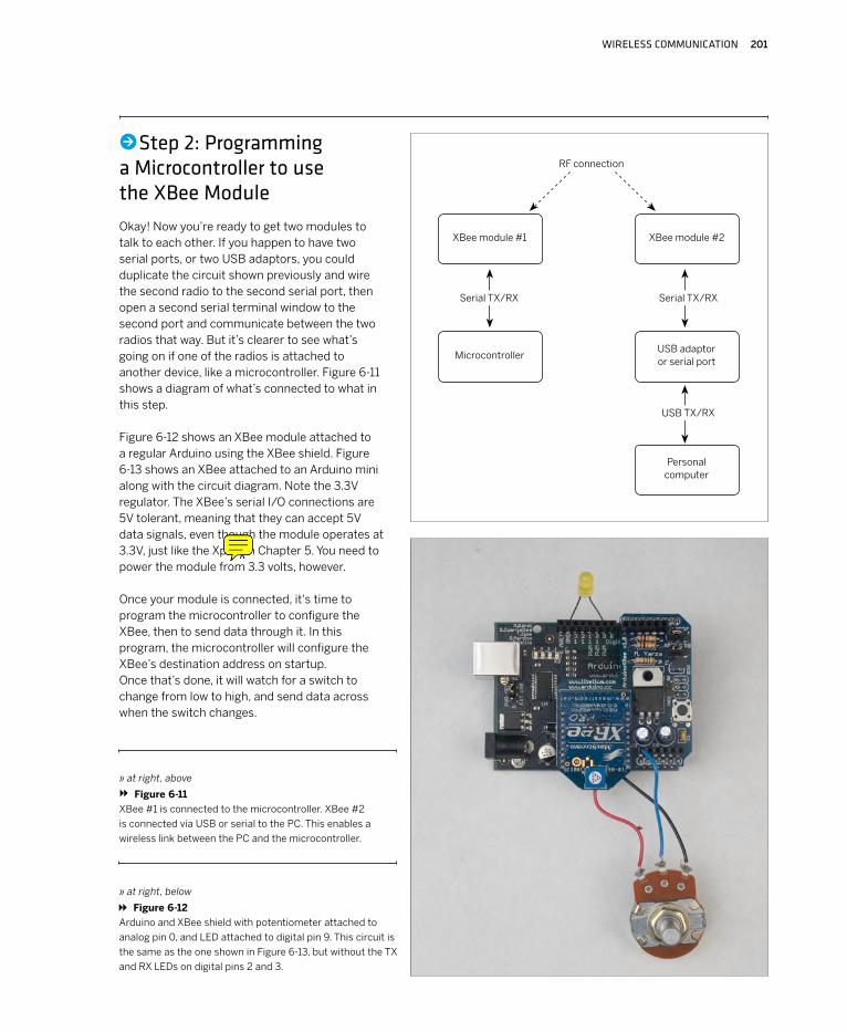
Okay! Now you’re ready to get two modules to talk to each other. If you happen to have two serial ports, or two USB adaptors, you could duplicate the circuit shown previously and wire the second radio to the second serial port, then open a second serial terminal window to the second port and communicate between the two radios that way. But it’s clearer to see what’s going on if one of the radios is attached to another device, like a microcontroller. Figure 6-11 shows a diagram of what’s connected to what in this step.
Figure 6-12 shows an XBee module attached to a regular Arduino using the XBee shield. Figure 6-13 shows an XBee attached to an Arduino mini along with the circuit diagram. Note the 3.3V regulator. The XBee’s serial I/O connections are 5V tolerant, meaning that they can accept 5V data signals, even though the module operates at 3.3V, just like the Xport in Chapter 5. You need to power the module from 3.3 volts, however.
Once your module is connected, it's time to program the microcontroller to configure the XBee, then to send data through it. In this program, the microcontroller will configure the XBee’s destination address on startup. Once that’s done, it will watch for a switch to change from low to high, and send data across when the switch changes.
» at right, above
Figure 6-11
XBee #1 is connected to the microcontroller. XBee #2
is connected via USB or serial to the PC. This enables a
wireless link between the PC and the microcontroller.
•Step 2: Programming a Microcontroller to use the XBee Module
» at right, below
Figure 6-12
Arduino and XBee shield with potentiometer attached to
analog pin 0, and LED attached to digital pin 9. This circuit is
the same as the one shown in Figure 6-13, but without the TX
and RX LEDs on digital pins 2 and 3.
XBee module #2XBee module #1
MicrocontrollerUSB adaptor or serial port
Personal computer
RF connection
Serial TX/RX Serial TX/RX
USB TX/RX
202 MAKING THINGS TALK
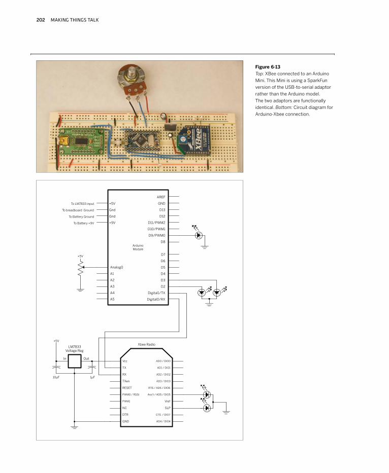
Figure 6-13
Top: XBee connected to an Arduino
Mini. This Mini is using a SparkFun
version of the USB-to-serial adaptor
rather than the Arduino model.
The two adaptors are functionally
identical. Bottom: Circuit diagram for
Arduino-Xbee connection.
WIRELESS COMMUNICATION 203
#define sensorPin 0 // input sensor
#define txLed 2 // LED to indicate outgoing data
#define rxLed 3 // LED to indicate incoming data
#define analogLed 9 // LED that changes brightness with incoming value
#define threshold 10 // how much change you need to see on
// the sensor before sending
int lastSensorReading = 0; // previous state of the switch
int inByte= -1; // incoming byte from serial RX
char inString[6]; // string for incoming serial data
int stringPos = 0; // string index counter
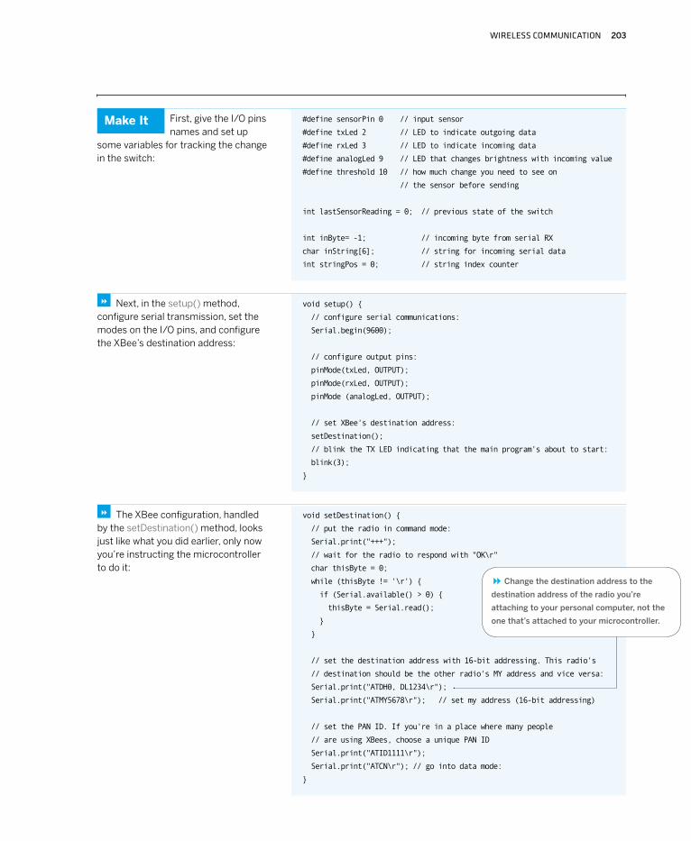
First, give the I/O pins names and set up
some variables for tracking the change in the switch:
void setup()
// configure serial communications:
Serial.begin(9600);
// configure output pins:
pinMode(txLed, OUTPUT);
pinMode(rxLed, OUTPUT);
pinMode (analogLed, OUTPUT);
// set XBee's destination address:
setDestination();
// blink the TX LED indicating that the main program's about to start:
blink(3);
Next, in the setup() method, configure serial transmission, set the modes on the I/O pins, and configure the XBee’s destination address:
8
void setDestination()
// put the radio in command mode:
Serial.print("+++");
// wait for the radio to respond with "OK\r"
char thisByte = 0;
while (thisByte != '\r')
if (Serial.available() > 0)
thisByte = Serial.read();
// set the destination address with 16-bit addressing. This radio's
// destination should be the other radio's MY address and vice versa:
Serial.print("ATDH0, DL1234\r");
Serial.print("ATMY5678\r"); // set my address (16-bit addressing)
// set the PAN ID. If you're in a place where many people
// are using XBees, choose a unique PAN ID
Serial.print("ATID1111\r");
Serial.print("ATCN\r"); // go into data mode:
The XBee configuration, handled by the setDestination() method, looks just like what you did earlier, only now you’re instructing the microcontroller to do it:
8
Change the destination address to the
destination address of the radio you’re
attaching to your personal computer, not the
one that’s attached to your microcontroller.
8
Make It
204 MAKING THINGS TALK
// Blink the tx LED:
void blink(int howManyTimes)
for (int i=0; i< howManyTimes; i++)
digitalWrite(txLed, HIGH);
delay(200);
digitalWrite(txLed, LOW);
delay(200);
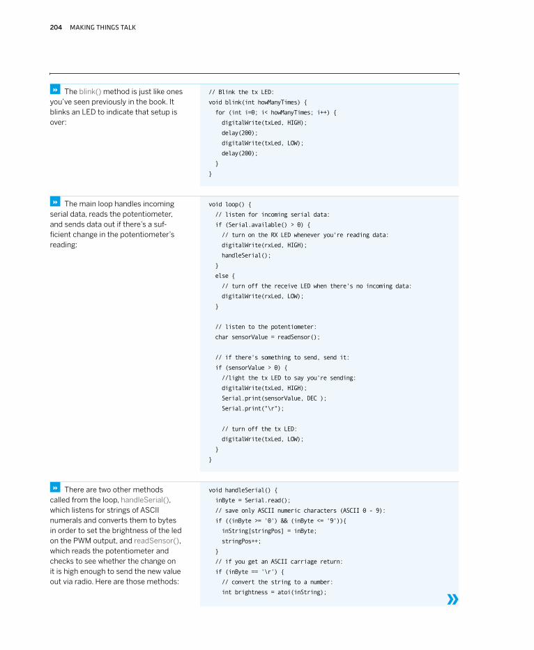
The blink() method is just like ones you’ve seen previously in the book. It blinks an LED to indicate that setup is over:
8
void loop()
// listen for incoming serial data:
if (Serial.available() > 0)
// turn on the RX LED whenever you're reading data:
digitalWrite(rxLed, HIGH);
handleSerial();
else
// turn off the receive LED when there's no incoming data:
digitalWrite(rxLed, LOW);
// listen to the potentiometer:
char sensorValue = readSensor();
// if there's something to send, send it:
if (sensorValue > 0)
//light the tx LED to say you're sending:
digitalWrite(txLed, HIGH);
Serial.print(sensorValue, DEC );
Serial.print("\r");
// turn off the tx LED:
digitalWrite(txLed, LOW);
The main loop handles incoming serial data, reads the potentiometer, and sends data out if there’s a suf-ficient change in the potentiometer’s reading:
8
void handleSerial()
inByte = Serial.read();
// save only ASCII numeric characters (ASCII 0 - 9):
if ((inByte >= '0') && (inByte <= '9'))
inString[stringPos] = inByte;
stringPos++;
// if you get an ASCII carriage return:
if (inByte == '\r')
// convert the string to a number:
int brightness = atoi(inString);
There are two other methods called from the loop, handleSerial(), which listens for strings of ASCII numerals and converts them to bytes in order to set the brightness of the led on the PWM output, and readSensor(), which reads the potentiometer and checks to see whether the change on it is high enough to send the new value out via radio. Here are those methods:
8
»

WIRELESS COMMUNICATION 205
Continued from opposite page.
// set the analog output LED:
analogWrite(analogLed, brightness);
// put zeroes in the array
for (int c = 0; c < stringPos; c++)
inString[c] = 0;
// reset the string pointer:
stringPos = 0;
char readSensor()
char message = 0;
// read the sensor:
int sensorReading = analogRead(sensorPin);
// look for a change from the last reading
// that's greater than the threshold:
if (abs(sensorReading - lastSensorReading) > threshold)
message = sensorReading/4;
lastSensorReading = sensorReading;
return message;
Notice that in the main loop, you’re not using any AT commands. That’s because the XBee
goes back into data mode (called idle mode in the XBee user’s guide) automatically when you issue the ATCN command in the setDestination() method.
Remember, in data mode, any bytes sent to an AT-style modem go through as is. The only exception to this rule is that if the string +++ is received, the modem switches to command mode. This behavior is the same as that of the Bluetooth module from Chapter 2, and as almost any device that implements an AT-style protocol. It’s great, because it means that once you’re in data mode, you can send data with no extra commands, letting the radio itself handle all the error corrections for you.
Once you’ve programmed the microcontroller, set the des-tination address on the computer’s XBee to the address of the microcontroller’s radio. (If you did this in the earlier step, you shouldn’t need to do it again.) Then turn the
potentiometer on the microcontroller. You should get a message like this in your serial terminal window:
120
The actual number will change as you turn the potentiom-eter. It will overwrite itself in the serial window, because you’re not sending a newline character (unless you are using the serial terminal Processing sketch shown earlier). Congratulations! You’ve made your first wireless transceiv-er link. Keep turning the potentiometer until you’re bored, then move on to step 3. X
NOTE: You might need to disconnect the
XBee’s receive and transmit connections to
the microcontroller while programming, if
your microcontroller is programmed serially
like the Arduino and Wiring modules are.
The serial communications with the XBee
can interfere with the serial communica-
tions with the programming computer.
Once the microcontroller’s programmed,
you can re-connect the transmit and
receive lines.
206 MAKING THINGS TALK
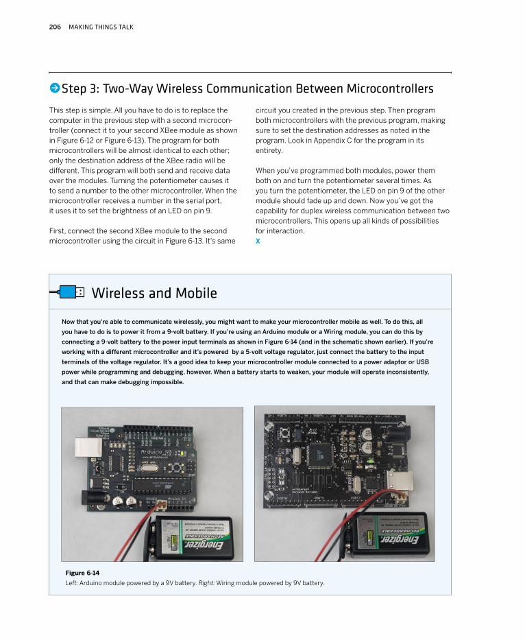
Now that you're able to communicate wirelessly, you might want to make your microcontroller mobile as well. To do this, all
you have to do is to power it from a 9-volt battery. If you’re using an Arduino module or a Wiring module, you can do this by
connecting a 9-volt battery to the power input terminals as shown in Figure 6-14 (and in the schematic shown earlier). If you’re
working with a different microcontroller and it’s powered by a 5-volt voltage regulator, just connect the battery to the input
terminals of the voltage regulator. It’s a good idea to keep your microcontroller module connected to a power adaptor or USB
power while programming and debugging, however. When a battery starts to weaken, your module will operate inconsistently,
and that can make debugging impossible.
Wireless and Mobile
Figure 6-14
Left: Arduino module powered by a 9V battery. Right: Wiring module powered by 9V battery.
•Step 3: Two-Way Wireless Communication Between Microcontrollers
This step is simple. All you have to do is to replace the computer in the previous step with a second microcon-troller (connect it to your second XBee module as shown in Figure 6-12 or Figure 6-13). The program for both microcontrollers will be almost identical to each other; only the destination address of the XBee radio will be different. This program will both send and receive data over the modules. Turning the potentiometer causes it to send a number to the other microcontroller. When the microcontroller receives a number in the serial port, it uses it to set the brightness of an LED on pin 9.
First, connect the second XBee module to the second microcontroller using the circuit in Figure 6-13. It’s same
circuit you created in the previous step. Then program both microcontrollers with the previous program, making sure to set the destination addresses as noted in the program. Look in Appendix C for the program in its entirety.
When you’ve programmed both modules, power them both on and turn the potentiometer several times. As you turn the potentiometer, the LED on pin 9 of the other module should fade up and down. Now you’ve got the capability for duplex wireless communication between two microcontrollers. This opens up all kinds of possibilities for interaction. X
WIRELESS COMMUNICATION 207
MATERIALS
2 solderless breadboards such as Digi-Key part number 438-1045-ND, or Jameco part number 206011 USB-to-TTL serial adaptor SparkFun’s BOB-00718 from Chapter 2 will do the job. If you use a USB-to-RS-232 adaptor such as a Keyspan or Iogear dongle, refer to Chapter 2 for the schematics to convert RS-232 to 5V TTL serial.2 Arduino modules or other microcontrollers2 BlueSMiRF Bluetooth modem modules from SparkFun2 potentiometers6 LEDs
»
»
»»
»»
In Chapter 2, you learned how to connect
a microcontroller to your personal
computer using a Bluetooth radio. This
example shows you how to connect two
microcontrollers using Bluetooth in a
similar manner.
As mentioned in Chapter 2, Bluetooth was originally intended as a protocol for replacing the wire between two devices. As a result, it requires a tighter connection between devices than you saw in the preceding XBee project. In that project, a radio sent a signal out with no awareness of whether the receiver got the message, and could send to a different receiver just by changing the destination address. In contrast, Bluetooth radios must establish a connection with each other before sending data over a given channel, and must break that connec-tion before starting a conversation with a different radio over that channel. The advantage of Bluetooth is that it’s built into many commercial devices today, so it’s a conve-nient way to connect microcontroller projects to personal computers, phones, and more. For all its complications, it offers reliable data transmission.
The modules used here, the BlueSMiRF radios from Sparkfun, use a radio from BlueRadios. The AT command set used here was defined by BlueRadios. Other Bluetooth modules from other manufacturers also use AT-style command sets, and they may execute similar functions, but their syntax is not the same. Unfortunately, Bluetooth radio manufacturers haven’t set a standard AT syntax for their devices.
Bluetooth Transceivers
•Step 1: Getting to Know the CommandsBecause the Bluetooth connection process involves many steps, it’s easiest to learn and understand it using a serial terminal program. Figure 6-15 shows the wiring to connect a BlueSMiRF radio to an FTDI USB-to-serial connector. If you’re not using the FTDI connector, you can use the MAX3323 circuit from Chapter 2 (Figure 2-3). Build this circuit, then connect it to your computer and open a serial connection to it at 9600 bits per second using your serial terminal program.
Figure 6-16 shows the connection you’re about to make. First, you’ll open a serial terminal window to connect to the radio’s serial interface, then you’ll open a second serial terminal window to connect via your computer’s Bluetooth radio to the BlueSMiRF’s radio. Your computer’s Bluetooth radio will show up as a second serial port on your computer, as it did after you established a pairing with it in Chapter 2 in Project #2, Wireless Monski Pong. If you didn’t make that pairing, this would be a good time to go back and do it.
The BlueSMiRF radios use an AT-style command set for command and configuration, and have two modes — command mode and data mode — just like the XBee radios. When you first power up a BlueSMiRF and connect to its serial interface, it’s in command mode. To see that it’s alive, type: AT\r. It will respond:
\r\nOK\r\n
All of the radio’s responses will be preceded and followed by a linefeed and carriage return as shown here. All of your input commands should be followed by a carriage return (press Enter or Return).
In order for one radio to connect to another, the second radio must be discoverable. In the BlueRadios syntax, a radio is discoverable when it’s in Slave mode. The radio connecting to it is said to be in Master mode. In this step,
Project 11

208 MAKING THINGS TALK
Figure 6-15
BlueSMiRF radio
attached to a USB-to-
serial adaptor.
WIRELESS COMMUNICATION 209
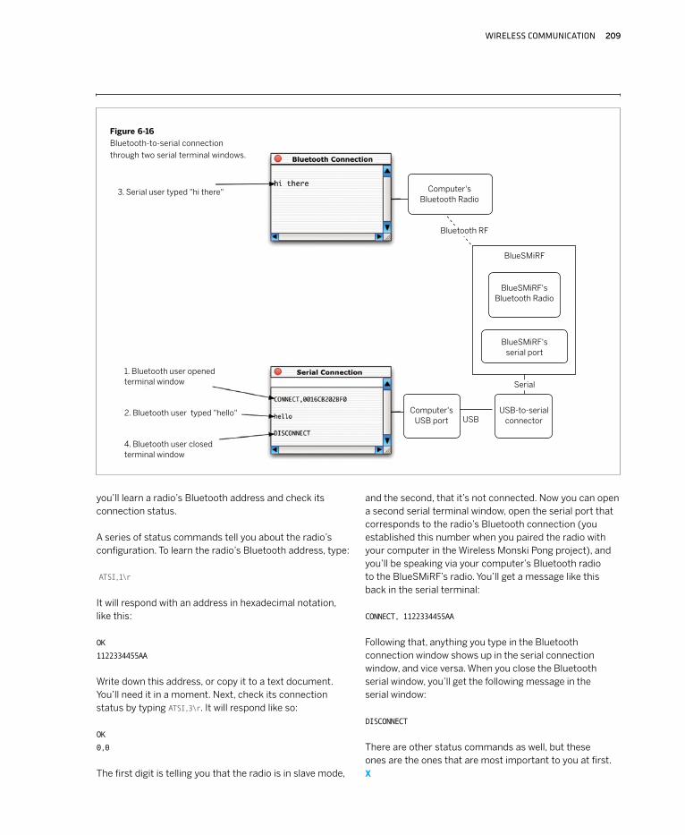
Figure 6-16
Bluetooth-to-serial connection
through two serial terminal windows.
you’ll learn a radio’s Bluetooth address and check its connection status.
A series of status commands tell you about the radio’s configuration. To learn the radio’s Bluetooth address, type:
ATSI,1\r
It will respond with an address in hexadecimal notation, like this:
OK
1122334455AA
Write down this address, or copy it to a text document. You’ll need it in a moment. Next, check its connection status by typing ATSI,3\r. It will respond like so:
OK
0,0
The first digit is telling you that the radio is in slave mode,
and the second, that it’s not connected. Now you can open a second serial terminal window, open the serial port that corresponds to the radio’s Bluetooth connection (you established this number when you paired the radio with your computer in the Wireless Monski Pong project), and you’ll be speaking via your computer’s Bluetooth radio to the BlueSMiRF’s radio. You’ll get a message like this back in the serial terminal:
CONNECT, 1122334455AA
Following that, anything you type in the Bluetooth connection window shows up in the serial connection window, and vice versa. When you close the Bluetooth serial window, you’ll get the following message in the serial window:
DISCONNECT
There are other status commands as well, but these ones are the ones that are most important to you at first. X
Computer's Bluetooth Radio
BlueSMiRF's Bluetooth Radio
BlueSMiRF's serial port
BlueSMiRF
Bluetooth RF
USB-to-serial connector
Computer's USB port
Serial
USB
3. Serial user typed "hi there"
1. Bluetooth user opened terminal window
2. Bluetooth user typed "hello"
4. Bluetooth user closed terminal window
210 MAKING THINGS TALK
Now that you’ve got basics of connecting and disconnecting, it’s time to connect to a microcontroller using Bluetooth. For this step, you’ll connect via the same USB-to-serial connection, but instead of speaking to your computer’s own radio, you’ll connect to a radio attached to a microcontroller.
First, get the Bluetooth addresses for both of your radios. You already wrote down one. Replace it with the second radio in your serial-to-USB circuit and follow the same steps to get that radio’s address as well.
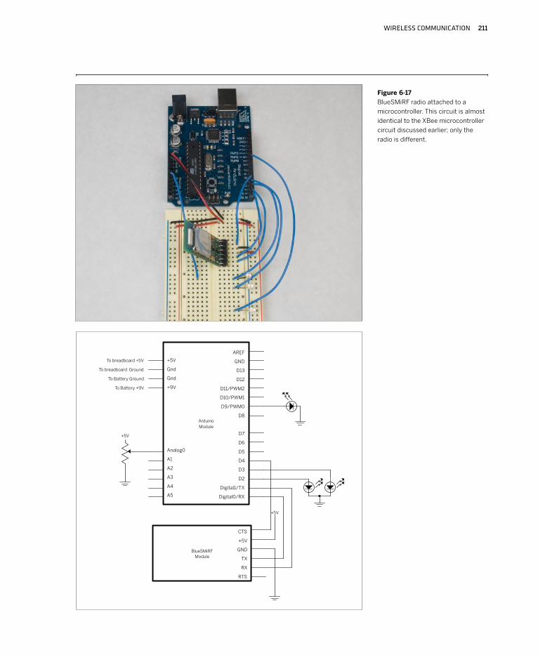
Next, build the microcontroller circuit shown in Figure 6-17. Just like the XBee example, it’s got a potentiometer attached to the analog pin so that you can send its values. There’s also a connection to the BlueSMiRF’s Clear-to-Send (CTS) pin. When the BlueSMiRF reads 5V on this pin, it stops sending data until the pin goes low again. You’ll use it to stop the BlueSMiRF sending serial data to the micro-controller when you don’t want it to.
NOTE: You’ll probably have to remove your BlueSMiRF while
programming the Arduino or Wiring boards, just as you’ve
had to for all other serial devices.
The program that follows connects to another BlueSMiRF with a set address, and when it connects, it sends its potentiometer value as an ASCII string, terminated by an asterisk, like this: 123*
Because there are so many newline characters and carriage returns in the AT command responses, it’s simplest just to use a terminator that isn’t used in the command set. That’s why you’re using an asterisk in this case.
Just like the XBee example, this program also looks for incoming ASCII strings (terminated by an asterisk this time) and converts them to use as a PWM value to dim an LED on pin 9.
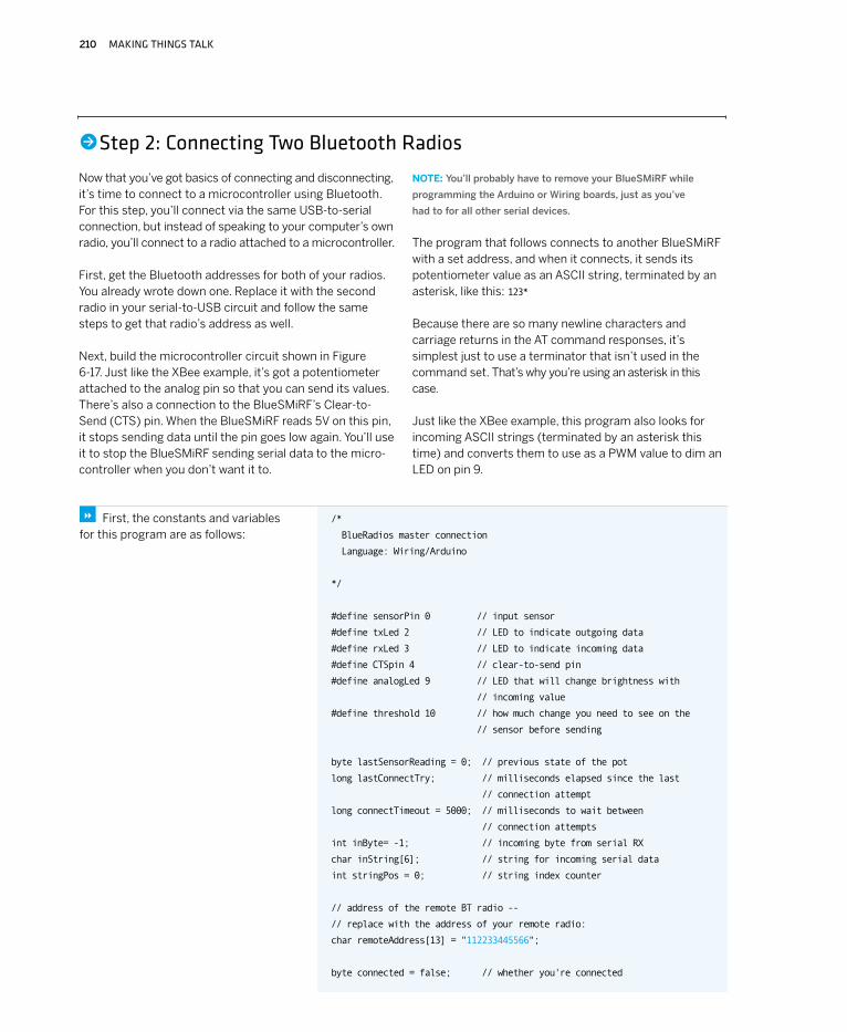
/*
BlueRadios master connection
Language: Wiring/Arduino
*/
#define sensorPin 0 // input sensor
#define txLed 2 // LED to indicate outgoing data
#define rxLed 3 // LED to indicate incoming data
#define CTSpin 4 // clear-to-send pin
#define analogLed 9 // LED that will change brightness with
// incoming value
#define threshold 10 // how much change you need to see on the
// sensor before sending
byte lastSensorReading = 0; // previous state of the pot
long lastConnectTry; // milliseconds elapsed since the last
// connection attempt
long connectTimeout = 5000; // milliseconds to wait between
// connection attempts
int inByte= -1; // incoming byte from serial RX
char inString[6]; // string for incoming serial data
int stringPos = 0; // string index counter
// address of the remote BT radio --
// replace with the address of your remote radio:
char remoteAddress[13] = "112233445566";
byte connected = false; // whether you're connected
First, the constants and variables for this program are as follows:
8
•Step 2: Connecting Two Bluetooth Radios
WIRELESS COMMUNICATION 211
Figure 6-17
BlueSMiRF radio attached to a
microcontroller. This circuit is almost
identical to the XBee microcontroller
circuit discussed earlier; only the
radio is different.
212 MAKING THINGS TALK
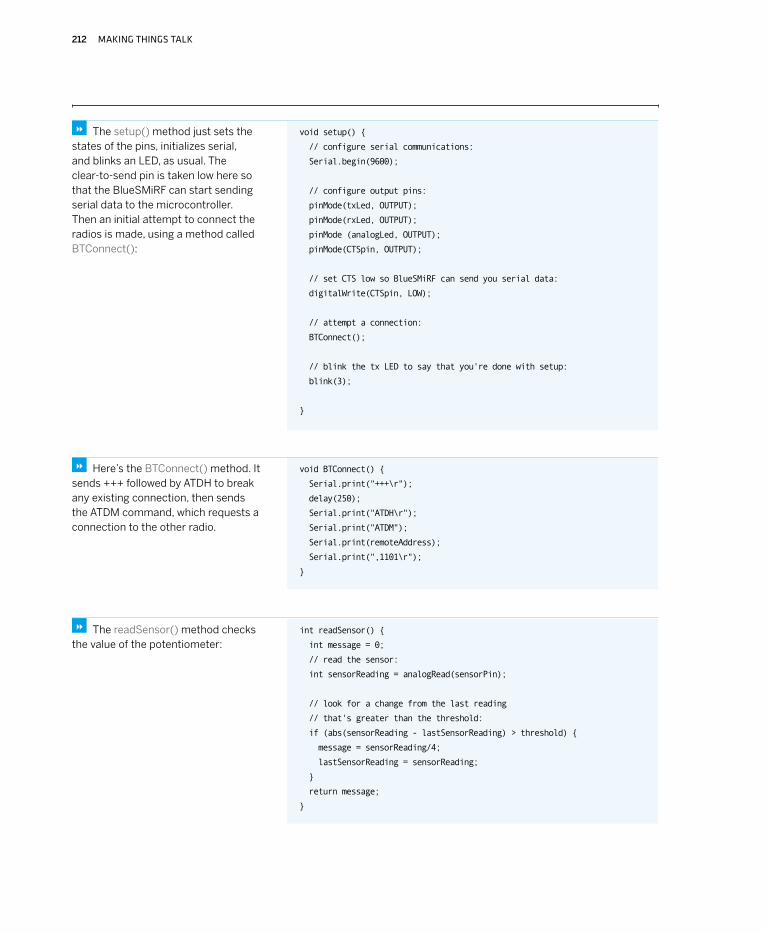
void setup()
// configure serial communications:
Serial.begin(9600);
// configure output pins:
pinMode(txLed, OUTPUT);
pinMode(rxLed, OUTPUT);
pinMode (analogLed, OUTPUT);
pinMode(CTSpin, OUTPUT);
// set CTS low so BlueSMiRF can send you serial data:
digitalWrite(CTSpin, LOW);
// attempt a connection:
BTConnect();
// blink the tx LED to say that you're done with setup:
blink(3);
The setup() method just sets the states of the pins, initializes serial, and blinks an LED, as usual. The clear-to-send pin is taken low here so that the BlueSMiRF can start sending serial data to the microcontroller. Then an initial attempt to connect the radios is made, using a method called BTConnect():
8
void BTConnect()
Serial.print("+++\r");
delay(250);
Serial.print("ATDH\r");
Serial.print("ATDM");
Serial.print(remoteAddress);
Serial.print(",1101\r");
Here’s the BTConnect() method. It sends +++ followed by ATDH to break any existing connection, then sends the ATDM command, which requests a connection to the other radio.
8
int readSensor()
int message = 0;
// read the sensor:
int sensorReading = analogRead(sensorPin);
// look for a change from the last reading
// that's greater than the threshold:
if (abs(sensorReading - lastSensorReading) > threshold)
message = sensorReading/4;
lastSensorReading = sensorReading;
return message;
The readSensor() method checks the value of the potentiometer:
8
WIRELESS COMMUNICATION 213
void blink(int howManyTimes)
for (int i=0; i< howManyTimes; i++)
digitalWrite(txLed, HIGH);
delay(200);
digitalWrite(txLed, LOW);
delay(200);
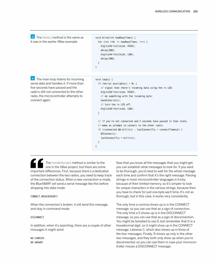
The blink() method is the same as it was in the earlier XBee example:
8
void loop()
if (Serial.available() > 0)
// signal that there's incoming data using the rx LED:
digitalWrite(rxLed, HIGH);
// do something with the incoming byte:
handleSerial();
// turn the rx LED off.
digitalWrite(rxLed, LOW);
// if you're not connected and 5 seconds have passed in that state,
// make an attempt to connect to the other radio:
if (!connected && millis() - lastConnectTry > connectTimeout)
BTConnect();
lastConnectTry = millis();
The main loop listens for incoming serial data and handles it. If more than five seconds have passed and the radio’s still not connected to the other radio, the microcontroller attempts to connect again:
8
The handleSerial() method is similar to the one in the XBee project, but there are some
important differences. First, because there’s a dedicated connection between the two radios, you need to keep track of the connection status. When a new connection is made, the BlueSMiRF will send a serial message like this before dropping into data mode:
CONNECT,0016CB202BF3
When the connection’s broken, it will send this message, and stay in command mode:
DISCONNECT
In addition, when it’s searching, there are a couple of other messages it might send:
NO CARRIER
NO ANSWER
Now that you know all the messages that you might get, you can establish what messages to look for. If you want to be thorough, you’d need to wait for the whole message each time and confirm that it’s the right message. Parsing strings in most microcontroller languages is tricky, because of their limited memory, so it’s simpler to look for unique characters in the various strings, because then you have to check for just one byte each time. It’s not as thorough, but in this case, it works very consistently.
The only time a comma shows up is in the CONNECT message, so you can use that as a sign of connection. The only time a S shows up is in the DISCONNECT message, so you can use that as a sign of disconnection. You might be tempted to use D, but remember that D is a hexadecimal digit, so it might show up in the CONNECT message. Likewise C, which also shows up in three of the four messages. Finally, R shows up only in the other two messages, and they both only show up when you’re disconnected, so you can use them in case your microcon-troller misses a DISCONNECT message.

214 MAKING THINGS TALK
void handleSerial()
inByte = Serial.read();
delay(2);
// comma comes only in the CONNECT,<address> message:
if (inByte == ',')
// send an initial message:
sendData();
// update the connection status:
connected = true;
//S comes only in the DISCONNECT message:
if (inByte == 'S')
// turn off the analog LED:
analogWrite(analogLed, 0);
connected = false;
//R comes only in the NO CARRIER and NO ANSWER messages:
if (inByte == 'R')
// turn off the analog LED:
analogWrite(analogLed, 0);
connected = false;
if (connected)
// save only ASCII numeric characters (ASCII 0 - 9):
if ((inByte >= '0') && (inByte <= '9'))
inString[stringPos] = inByte;
stringPos++;
// if you get an asterisk, it's the end of a string:
if (inByte == '*')
// convert the string to a number:
int brightness = atoi(inString);
// set the analog output LED:
analogWrite(analogLed, brightness);
// put zeroes in the array
for (int c = 0; c < stringPos; c++)
inString[c] = 0;
// reset the string pointer:
stringPos = 0;
// as this byte (*) is the end of an incoming string,
// send out your reading in response:
sendData();
The sequence for this handleSerial() method is a bit complicated, so Figure 6-18 shows it in a flowchart. The actual code follows:
8
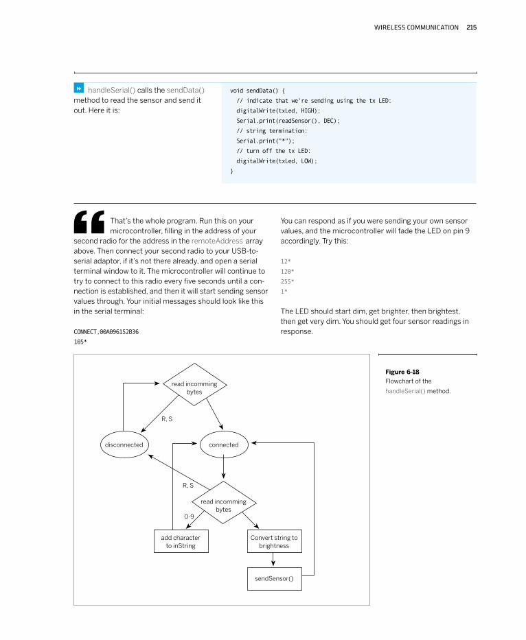
WIRELESS COMMUNICATION 215
Figure 6-18
Flowchart of the
handleSerial() method.
void sendData()
// indicate that we're sending using the tx LED:
digitalWrite(txLed, HIGH);
Serial.print(readSensor(), DEC);
// string termination:
Serial.print("*");
// turn off the tx LED:
digitalWrite(txLed, LOW);
handleSerial() calls the sendData() method to read the sensor and send it out. Here it is:
8
That’s the whole program. Run this on your microcontroller, filling in the address of your
second radio for the address in the remoteAddress array above. Then connect your second radio to your USB-to-serial adaptor, if it’s not there already, and open a serial terminal window to it. The microcontroller will continue to try to connect to this radio every five seconds until a con-nection is established, and then it will start sending sensor values through. Your initial messages should look like this in the serial terminal:
CONNECT,00A096152B36
105*
You can respond as if you were sending your own sensor values, and the microcontroller will fade the LED on pin 9 accordingly. Try this:
12*
120*
255*
1*
The LED should start dim, get brighter, then brightest, then get very dim. You should get four sensor readings in response.
connected
sendSensor()
R, S
R, S
0-9
disconnected
Convert string to brightness
read incomming bytes
read incomming bytes
add character to inString
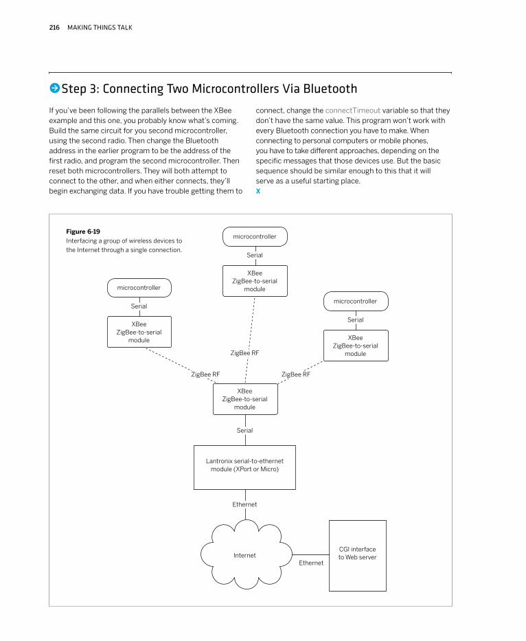
216 MAKING THINGS TALK
If you’ve been following the parallels between the XBee example and this one, you probably know what’s coming. Build the same circuit for you second microcontroller, using the second radio. Then change the Bluetooth address in the earlier program to be the address of the first radio, and program the second microcontroller. Then reset both microcontrollers. They will both attempt to connect to the other, and when either connects, they’ll begin exchanging data. If you have trouble getting them to
connect, change the connectTimeout variable so that they don’t have the same value. This program won’t work with every Bluetooth connection you have to make. When connecting to personal computers or mobile phones, you have to take different approaches, depending on the specific messages that those devices use. But the basic sequence should be similar enough to this that it will serve as a useful starting place. X
•Step 3: Connecting Two Microcontrollers Via Bluetooth
Figure 6-19
Interfacing a group of wireless devices to
the Internet through a single connection.Serial
microcontroller
Serial
microcontrollerSerial
microcontroller
Serial
Ethernet
Ethernet
XBee ZigBee-to-serial
module
XBee ZigBee-to-serial
module
XBee ZigBee-to-serial
module
XBee ZigBee-to-serial
module
Lantronix serial-to-ethernet module (XPort or Micro)
InternetCGI interface to Web server
ZigBee RF
ZigBee RFZigBee RF
WIRELESS COMMUNICATION 217
In Project #5, you connected a microcontroller to the internet using a Lantronix Micro serial-to-Ethernet module. You could replace the Micro with a WiMicro and build the exact project, with only some minor configuration changes on the WiMicro.
It’s worth mentioning why Wi-Fi isn’t more pervasive in embedded wireless projects. First, there’s the cost. Most of the serial-to-Wi-Fi modules on the market are more expensive than equivalent transceivers implementing other protocols. For example, the WiMicro costs about $165. DigiConnect’s equivalent module, the plaintively named Wi-ME, costs about $130. Other wireless Ethernet-to-serial modules on the market are in the same price range — over $100. When compared to $20 for XBee and other serial transceivers, or even the $60 price range typical for many Bluetooth modules, Wi-Fi isn’t exactly a bargain.
Besides the cost, however, there’s another factor to consider before going Wi-Fi. Most Wi-Fi modules consume more electrical power than the other radio types mentioned here. Because one of the main reasons for going wireless is to go mobile, you’ll be eating up battery life with Wi-Fi radios. So they’re great when they’re conve-niently already built into a product, but if you’re building from the ground up, it’s worth considering other alterna-tives. One common solution for wireless projects that need Internet access is to make an RF-to-Ethernet bridge. For example, one of the XBee radios from the earlier project could be interfaced to a Lantronix XPort or Micro module to act as the Internet connection for a whole collection of XBee-enabled objects. Figure 6-19 shows a typical network setup for such a system. X
What About Wi-Fi?So far, you’ve seen the most basic serial radios in action in the transmitter-receiver
project, and more advanced radios in the transceiver projects. If you’re thinking about
networks of microcontrollers, you’re probably wondering whether you can connect your
projects to the Internet and to each other using Wi-Fi. The answer is: yes, you can.
The wisest thing you can do when buying your radios is to buy them as a set. Matching a transmitter from one company to a receiver from another is asking for headaches. They may say that they operate in the same frequency range, but there’s no guarantee. Likewise, trying to hack an analog radio, such as that from a baby monitor or a walkie-talkie, may seem like a cheap and
easy solution, but in the end, it’ll cost you time and eat your soul. When looking for radios, look for something that can take the serial output of your microcontroller. Most microcontrollers send serial data at TTL levels, with 0V for logic 0 and 3.3V or 5V for logic 1. Converting the output to RS-232 levels is also fairly simple, so radios that can take those signals are good for your purposes.
Buying RadiosYou’ve seen a few different kinds of wireless modules in this chapter. Though they
do the job well, they’re not the only options on the market. You should definitely shop
around for modules that suit your needs. Following are a few things to consider in
choosing your radios.
218 MAKING THINGS TALK
If you opt for the least expensive solutions, you can just implement a one-way wireless link with transmitter-receiver pairs and send the message again and again, hoping that it’s eventually received. If you spend a little more money, you can implement a duplex connection, so that each side can query and acknowledge the other. Regardless of which method you choose, you have to prepare for the inevitable noise that comes with a wireless connection. If you’re using infrared, incandescent light and heat act as noise, and if you’re using radio, all kinds of elec-tromagnetic sources act as noise, from microwave ovens to generators to cordless phones. You can write your own error-checking routines, but increasingly, wireless protocols
like Bluetooth and ZigBee are making it possible for you to forget about that, because the modules that implement these protocols include their own error correction.
Just as you started learning about networks by starting with the simplest one-to-one network in Chapter 2, you started with wireless connections by looking at simple pairs in this chapter. In the next chapter, you’ll look at peer-to-peer networks, in which there is no central control-ler, and each object on the network can talk to any other object. You’ll see both Ethernet and wireless examples. X
ConclusionWireless communication involves some significant differences from wired communication.
Because of the complications, you can’t count on the message getting through like you
can with a wired connection, so you have to decide what you want to do about it.
Consider the data rate you need for your application — and, more specifically, for the wireless part of it. You may not need high-speed wireless. One common use for wireless communication in the performance world is to get data off the bodies of performers without a wired con-nection, in order to control MIDI performance devices like samplers and lighting dimmers. You might think that you need your radios to work at MIDI data rates to do this, but you don’t. You can send the sensor data from the perform-ers wirelessly at a low data rate to a stationary microcon-troller, then have the microcontroller send the data on via MIDI at a higher data rate.
Most of the inexpensive radio transmitters mentioned previously send data at relatively low rates (under 9600 bps). Given the noisy nature of RF, it’s wise to not attempt to send at the top speed if you don’t need to. In the trans-mitter-receiver project, the radio pair can operate at up to 4800 bps, but you are sending at only 2400 bps. Try it at
4800 bps, and you’ll notice more errors. The 2.4Ghz radios used for Bluetooth, ZigBee, and wireless Ethernet are exceptions to this rule. They generally operate reasonably at much higher data rates, because they’ve got a micro-controller on board to manage the data flow.
Consider the protocols of the devices that you already have at your disposal. For example, if you’re building an object to speak to a mobile phone or a laptop computer, and there’s only one object involved, consider Bluetooth. Most laptops and many mobile phones already have Bluetooth radios onboard, so you’ll need only one radio to do the job. It may take some work to make your object compatible with the commands specific to the existing devices you’re working with, but if you can concentrate on that instead of on getting the RF transmission consistent, you’ll save yourself a lot of time. X
Urban Sonar by Kate Hartman, Kati London, and Sai Sriskandarajah. The jacket contains four ultrasonic sensors and two pulse sensors. a microcontroller in the jacket communicates via Bluetooth to your mobile phone. The personal space bubble as measured by the sensors and your changing heart rate as a result of your changing personal space paint a portrait of you that is sent over the phone to a visualizer on the internet.

WIRELESS COMMUNICATION 219