18. 2 fire damper
TRANSCRIPT

-// \\/ / / \ \
II
\ \ \ t / , ,
\\ /2
JACKSON
MODEL
5650DROP LOCK FIRE DAMPER
-// \\/ / I \ \
It
t \ \I
\\ /2

JACKSONWWffiWWffiffi
Model 5650 Jackson Fire Domper is 4 hour rotedin brickwork WITHOUT A IINTEL BEAMcomplies with ASl 682..| - I 990TESTS - FSPOIA', FSPOI46
Approved by Jobqtqn Bombo DonPenyelqmqf, Mqloysio.
Also 2 hour roted in plosterboord woll.WITHOUT SUPPORT RODS. ComPlieswirh ASl 682.1 1990 TEST FSV0]00
5. Double oction stoinless steel spring with blodedimples, provide positive shut off. (potentpending).
6. Single hond reset from either side.
Approved UL33 fusib le l ink ( . |65 'F- 74"C1 incloied hook for eosy n'eplocement. (No tools).
Lightweight construction without welding ensuresth; integiity of the dompers golvonised cooting.
Recessed ongle design permits o row edge gosyduct ottochmlnt, with breokowoy chorocteristics -
no fostening screws required.
Chonnel f longes cCIn be supplied to suit TDF orf longed ducfwork. 25mm or 38mm.
l .
2.
3. Hos o leokoge rote of only20"/oof pertiissible qir leqkogeAS1 682. r -1990.
4. Moximum cleor oir possoge.
5s
trrl2001 8 01 6 01401201 0 0BO604020
U S OKPa 0 .25 0 .50 0 ]5 1 .00 1 .25
- - Permissible Air Flow - in occordonce with I 682.1-.|990.5= Jackson5650F Fire Domepr meosured Air Flow,
(Test #323) (Domper Size 400 x 2501
7.
8.
9.
10 .

JACKSON
I l. Optionol metol seols ollow domper tobe instolled insitu with controlled lOmmexponsion gop, (AS 1682.2'1990). Thismeons no instollotion or inspection costsplus eliminotion of heolth hozordousfibres (Austrolion potent no.- 6242881.
GERTIFIGATES @F TCSTSNo t2O & tZS
-// \\/ / l \\
It
r \ \ II
\\ /2
. , N o . 3 z o
W,uf:'-r"/i/*,T b i . s i s t o c e d i f y t h a t t h e e l e d e o t o f c o a s t r u c t i o D d e s c r i b e d b e l o ! k a s
t € . t € d b y t h e c s l R o D i v i s i o r o f B u i I d i n g , c o r s t r u c t l o n a n d E n g i D e e r i t r g i n
a c c o r d a D c a d i t b A u s t r a l i a d S t a o d a r d 1 5 3 0 ? M e t b o d s f o r f i r e t e s t s o r b u i r d i l g
u t a r i a l 6 , c o d p o r e u t s a i d s t n c t u r e s P a r t 4 _ 1 9 9 o , F i r e - r e s i s t a D c e t e s t s o f
€ l d e d t s o f b u i l d i n g c o n s t r u c t i o r o n b e h a l f o f
J n c k s o n I n t e r n a t i o n a l P t y L i m i l e d
8 P i k e S t r e e ! . R I D A L Y E R E , N s t s
A f u l l d e s c r i P t i o n o f t b e t e s t s P e c i E e D a D d t h e c o n p l e t e
d € t a i l e d i ! t b e D i v i s i o n ' s r e P o r t F S P 0 1 4 5
d a m p e r a s s e m b l y m o u n t e d j n a b r i c k w a l l .
S tnc tura l Adequacy
Ia tegr i ty
t s 6 t b g O f f i c e r : L B R e l s . n D a t € o f T e s t : 1 , l : t v 1 9 _ a l
(|lilll)
D 6 6 c r i - p t i o s : T h e 4 O O m w i d e x 2 0 0 m h i q h f i r e d a n p e . w a s a h i n g e d f l i pl y p e . f a b r i c a t e d f r o m c a l v a b o n d s t e e r ( 1 . 2 m t h i c k f o r r h e
c a s i n g a n d 1 . 0 t u n t h i c k f o r t h e b l a d e j w i t h s p r r n g a . s : r t e d
c l o s u r e a n d l e L e a s e d b y a f u s i b l e l i n k - r h e d ; m p e r w a s l r u r l t
r n l o a b r i c k { a 1 I w r t h q a L v a n i s e d s t e e L c a s i n g s e a l s b c t w e e nt h e d a r p e ' c d s i n o - r , d t h e b r r c k w o r L j r p : d - - o i . o m p r " . c r l . ,f i b r e s e a L s . c o n s ! r u c t i o n i s d e l a i l e d i .
. d r a w i n g s n u d e r e d 5 6 4 1 0 R e v i s i o n A , d a t e d 1 5 u a r c h 1 9 9 1 ,5 6 F - 1 1 a n d 5 6 r - 1 2 b o t h C a r e d 3 A u g u s r 1 9 9 0 , 5 6 F - 1 3 ,5 6 F - 1 4 , 5 6 F - 1 5 R e v i s i o n A , 5 6 F - l l , 5 5 1 - 1 9 , 5 6 F - 2 0 a n d5 5 F - 2 1 a l l d a t e d 1 5 H a r c h 1 9 9 1 a n d a l l b y J a c k s o nl n t e r n a t i o n a l F l y L i n t i t e d .
. d r a p i n g s A - 5 5 5 1 - 7 v , d a r e d 2 9 J u I y 1 9 a 4 , A - 5 5 2 2 , d a t e c 1 7u a r c h l 9 ? 7 a n d A - 5 6 9 1 , d a t e d 1 6 S e p i e m b e r 1 9 a 2 , a l l b yp r e f c o p r o d u c r s I n c .
n o o l e i e o t o f c o a s t n c t i o d d e s c r i b e d a b o v e s a t i s f i e d t b e f o l l o r i n g c r i t e r i af o r f i r e - r e s i s t a l c e f o r t h e p e r i o d s t a t e d
-.
&rr/i.rr"r1,/rutT h i s i s t o c e r t r f y t h a r t b e e l e d e r t o f c o i s t r u c L i o r d e 5 c r i b e d b e l o - w n s
t e s t e d b y t b e c s I R o D i v i s i o o o f B u i l d i D g , c o d s t r u c t i o n a D d t r i l q j . n e e . i D 9 f o r a i r
r e a k a g e i n a c c o r d a n c e e t l h A u s t r a l i a r s t a n d a r d 1 5 8 2 . t - 1 t 9 o s e c t i o n 5 o n b e h a l t
j";f:".i:::::":i;tii,i:: l:;""'A f u ] l d e s c r i p t i o D o f t h e t e s t
r e s r s t a r c e t e s t r e p o r t o " o u a n u
P r o d u c t N a o e : i h e s p o n s o r i d e n l - i f i e d . h . r s p e L - i n i e n . 1 r j a n r c i t r . 5 6 : a F i i . { _ -danp: r as5pt r ,Dty .
D e s c r i p t i o D : T h e 4 0 0 M r w i d e x 2 5 0 r n h i q h f i r e d . m f e r a a s . r h r n q e . t i _ a l lt y p e / f a b r i c a t e d f r o m c a L v a b o n d s l e e t ( 1 . : i r r t h r . ! 1 . r r h . .c r s i n a a n d 1 . 0 n m t h i c k f o r t h e b l a d c ) r r L r L j t : : r l : l
c L o s u r e a n d r e l e d s e d b y a i u s i t r t e t r i l k .c o n s t . u c r i o n i s d e r a i l e d i i i. o r a w r n g s n u d e : e d 5 6 F 1 0 R e v r s i o . B / C a L . r . t t 5 x - f . h t . t 9 t ,
5 6 f 1 t a i d 5 6 F , t 2 b o t h d a L e d I A u J u s t t 9 ! 0 , ! a a - t : 1 ,5 € t s - 1 4 , 5 6 F - 1 5 R e v i s i o n t , 5 6 F - 1 7 , 5 6 t . - i 9 , ! a i : ! a n , j5 6 F - 2 1 a t L d a t e d t 5 u a r c h 1 9 9 1
_ o r a w r n g s A - 5 5 5 i _ ? v . d a t . d 2 9 J u i y 1 9 8 4 , n 5 6 2 t , d : ! e , t t 7M a r c h 1 9 7 7 a n d A 5 6 9 i , . i , r ' : e d t a s e p r e m b o r 1 9 6 : , a i L ) r rp r e f c o i r r o d u c t s I n c .
a E s T R E s u L T s : 1 h e f c l l o w i n g r . e s u t r s H e . e o b t a i n e l t .
A IR PRESSIJRE EASURED pEts l ISSIBLe
DIFFEREN?IA! A IR FLOW i l IR FLOW( k P a ) t L / s ) \ L / E )
1 7 . C 9 5O . 5 O 2 1 . A \ 2 to . t 5 3 1 . 5 i 5 tl . o 0 3 5 . 5 1 / :1 . 2 5 4 2 - a 1 9 !
a n . t r h e . o i . r e i n r e r n 5 o f A s l 6 6 ? . t : ! : C c t a u : : e : . 1 ( . 1 r t r Ep e r t . r n r 3 r 1 c € , c f r 5 e f i . . i a r F e r a . j { r n L t . , .. a L : s f . c r o r ,
l( J WqJ-,R J D a y e h
f o r k n a g e r , F i r e T e c h D o l o g y _
Divbion of Bui lding. Cotuhcbon od tnsncqna
r c B o r 3 1 0 N O R ' I ' I ] R y D ! N s w 2 1 1 l T c i e r h @ c ( m ) 8 E E 8 1 8 8 F u ( 0 t ) 6 E 8 9 j I j
fflll)

JACKSON
TCGHNNGAI DETANES. The model 5650 is Jackson's lotest smoll domper technoloqy. Becouse it employs o sinole too
pivot blode which tucks up completely behind the frome flonge even l00mm high dori'pers'con oe provtded wtth very htoh tree oreo.
. The domper fror" pr"r",it, o"nly o 1Omm intrusion into the opening moking these oompersideol tor openinq sizes 200mm ond below.
. This domplr is.iJeol. fo.q tojlgt exhoust, smoll corridor openings, etc, where typicol domperdesiqns offer obout holf of the free oreo *hen mode sroll iriheloht
' The Model 5650 fire dompers ore monuloctured from golvoniseJ steel sheet complying withASl39Z with o cootinq closs of 2275.
r Domper bodies ond su-.round ongles ore formed lrom l.2mm T.C.T. moteriol with blodes lroml-Omm T.C.T. Closure springs ore type 301 high yield stoinless steel ond oll fostenings oreztnc oloted steel.Moximum sizes ovoiloble ore nominol 400mm wide x 250mm high for brick wolls ond400mm wide x200mm hiqh for plosterboord wolls.D^ompers ore ovoiloble in-two dilferent style configurotions for duct or grille opplicotions.(See illustrotion).Speciol. frome configurotions con be monufoctured to suit lorge proiect opplicotions byconlocflno our tocot otttces.stock size-s ovoiloble ot shorr norice in widths of 150, 200, 250, 300 ond 400 combined withheights of 100, 150 ond 200. Intermediote sizes ore monufoctured to order.
WALL WALLIMPORTANI The body Style'GS' is the some outsidedimensions os SVle 'D'.
Grilles or reqisters will needto fit in o cle"or openinglOmm less thon nominolsize (Exomple: Nominol200 x 200 will hove o cleoropening of tg0 x
. |90).t lIJJ{J
r \
\t!Nar)t-r \
!
AIR
€FLOW
STYLE ''GS"
\l
txNof-
L l lN I
v)F
STYLE "D"
Manufactured under licensed in Malaysia by:
NAM FOONG (M) SDN BHD (8070_T)No. 29, Persiaran Segambut Tengah, 51200 Kuala Lumpur.
Tel : 03-6258 9338 Telefax :t)3-6251 5689E-mail : [email protected] Website : www.namfoong.com

JACKSON
IMPORTANT: No lintel beom is requiredbut the verticol ioint of the brick courseobove the domper should be ot the centreof the domper. Verticol iointsin the brick course obove the dompershould olso be completely filled wiihmortor.
C. PIASTERBOARD WAIICI. Ensurewoll penetrotion is correct size. Opening should be lOmm lorger thon nominol
size in both width ond heioht.DGMPIE: 400 wide * ZbO high domper requires opening
4,l0 wide x 210 high (See lllustrotion).C2. Remove flonqe screws ond deioch flonoes from domoer cosino.C3. Apply beod 6f Nullifir" M70l fire rotetr mostic to bose of penlkotion ond oround
penetroiion where fixed onqles seol oqqinst fire roted plosierboord.C4. Slide domper into woll pen6hotion onl locote in centre of penetrotion.
NOTE: Dompers ore cleorly lobelled with oir flow direction ond top of unit.C5. Pock exponsion gop ot top of domper with 22mm dio IBS rod ond seol top ond sides
with MZOI mostic o minimum of 5mm thick.C6. Reploce flonges with beod of UZOt oround penetrotion where ongles seol ogoinst
plosterboord.NOTE: Do not overtighten flongescrews.
C7. Commission domper ond conneci ductwork os per clouse 46 qnd AZ.
ftffiAHffiffiffiffiAffiffiffiDompers should be mointoinedin occordonce with ASl85l ,Port 6-l 983.
WALL
WALL
Manufactured under licensed in Malaysia by:
NAM FOONG (M) SDN BHD (8070-T)No. 29, Persiaran Segambut Tengah , 51200 Kuala Lumpur.
Tel : 03-6258 9338 Telefax : 03-6251 5689E-mail : [email protected] Websire : www.namfoong.com
Manufactured Under Licensed In Malaysia By:
NAM F00NG (M) SDN. BHD. (8o7o.T)29, Persiaran Segambut Tengah, 51200 Kuala Lumpur.Tel: 603-62589338 Telefax: 603-62b1bOBgE-mail: [email protected] Website: www.namfoong.com
M. & E. AIR CONTROL PTY. LTD.
L ICENCEE
SPECIAL R. A. FIRE OAMPER.AUSTRALIA SOUARE TOWER
SYONEY N. S. W.
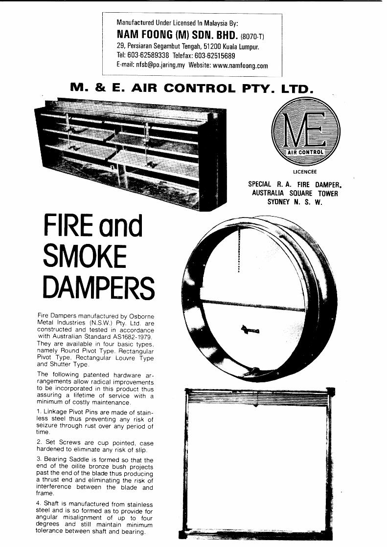
FIRE ondSMOKEDAMPERS
Fire Dampers manufactured by OsborneMetal Industr ies (N.S.W.) Pty. Ltd. areconstructed and tested in accordancewi th Austra l ian Standard AS1682-1929.They are avai lab le in four basic types,namely Round Pivot Type, RectangularPivot_ Type, Rectangular Louvre fyp"and Shutter Type
The fol lowing patented hardware ar-rangements al low radical improvementsto be incorporated in this product thusassuring a l i fet ime of service with amin imum of cos i ly maintenance.1. L inkage Pivot Pins are made of s ta in-less steel thus preventing any r isk ofseizure through rust over any period oft ime .
2. Set Screws are cup pointed, casehardened to e l iminate any r isk of s l ip .3. Bearing Saddle is formed so that theend of the oi l i te bronze bush projectspast the end of the blade thus producinga thrust end and e l iminat ing the r isk oJinterference between the blade andf rame.
4. Shaft is manufactured from stainlesssteel and is so formed as to provide forangular misal ignment of up to fourdegrees and st i l l mainta in min imumtolerance between shaft and bearing.

DESCRIPTIONFire dampers manufactured by M. & E. are constructed
Standard A30-1958 for various fire ratings and meet the
Semi-Government Departmonts, Fire Control Authorities,
Councils throughout the British Commonwealth.
Shaft is manufactured
misalignmont of up tobearing.
and tested in accordance with Australian
requirements of Government Departments,
Fire and Accident Underwriters and Local
They are available in three basic types, as shown on the following pages, namely Round Pivot
Typo, Rectangular Pivot Type and Rectangular Louvre Type. The maximum module sizes of the
dampers as shown on the following pages does not limit the maximum size of damper as this
can be achieved by coupling two or thres modules together.
These fire dampers are unique in their design in as much that thc best possible materials are
used but at a fraction of their regular cost should conventional methods have been employed. The
detail sketches show the patented hardware arrangement which allows these radical improvements,
to be incorporated in this product thus assuring a lifetime of service with a minimum of costly
maintenance.
Check These Features
Pending
1 .
3.
from stainless stcel and is so formed as to provide for angular
four degrees and still maintain minimum tolerance between shaft and
# 6LINKAGE ASSEMBLY BEARING ASSEMBLY
Linkage pivot pins are made of stainless steel thus preventing any risk of seizure through
rust over any period of time.
2. Set screws are cup pointed, case hardened to eliminato any risk of slip.
Eearing saddle is formed so that the end of the oilite bronze bush projects past the end of
the blade thus producing a thrust end and eliminating the risk of interference between the bladeand frame.
4.

TYPICAL SPECIFICATION
The Damper B lades sha l l have
bear ings . Any in te r -connect ing
s t e e l p i n s a n d d a m p e r s s h a l l b e
Access doors where requ i red
l inks , rese t t ing o f dampers and
Wri t ten below is a typical speci f icat ion cover ing the design and manufacture of approved f i re
d a m p e r s .
Fire dampers shal l be instal led where shown on drawings and wherever required to meet local
regulat ions as la id down by any author i ty having jur isdict ion over the said works. They shal l be
constructed and tested in accordance with Austral ian Standard A30-1958, Sect ion four, and any
subsequent amendments , fo r a f i re ra t ing equ iva len t to the sur round ing cons t ruc t ion , and sha l l
be ins ta l led in s t r i c t accordance w i th the manutac turer ' s recommendat ions and in compl iance w i th
acceptance cer t i f i ca tes fu rn ished by the manufac turer .
se l f a l ign ing s ta in less s tee l sha f ts and sha l l p ivo t in o i l i te b ronze
l inkages required for louvre type dampers shal l p ivot on stainless
he ld open by one or more fus ib te l inks wh ich sha l l fuse a t 68 "C
shal l be provided to each f i re damper for replacement of fusible
fo r per iod ica l inspec t ion o f the f i re damper .
SPECIAL FRAME ARRANGEMENTS
drawings in th is ca ta logue show the Standard F i re Damper f rame ar rangements bu t shou ld
pro jec t requ i re spec ia l cons idera t ion , t ra ined personne l a re a t your d isposa l .
The
any
ORDERING INSTRUCTIONS
When ordering nominate the fol lowing:-
1. rvpe No. l
2. Nominal Width l ot DiameterI
3. Nominal Height )
4. Wall or Slab Thickness
INSTALLATION
The prob lems invo lved when ins ta l l ing f i re dampers are usua l ly numerous bu t no t so w i th the
M. & E. product. Dampers are suppl ied complete wi th fusible l inks f i t ted and with matching angle
f lange surrounds al l pre - punched with s lot ted holes to al low for general bui ld ing to lerances.
Study of the detai l instal lat ion sketches wi l l show the obvious savings in erect ion t ime that wi l l
resul t in the use of th is product.

Ilrltvl
\xt,!{atll{{
\3tT{0
\Itl]\l0tut4\\fi
IoNiNuitDq$0u\tsttl
t
\\\t{rt
\tIuaItt4
4^i,1
t.,t$
tt
ttIelIt0!
r$ii
Io\\tttq
II{{n)
.\tlI.\IIq
i{x|\q.
N${\\i\\
IIIr)0Il'{!{t
Iql.l0ttUtqiI
Tx \IilItorl{{
ItI
I0\ItartI0ttI0tII{
ItT
i$r\
Tl*
rlli'liirt'tI
lliII.i
L(l{0{taIY
$Ih\tI{
Ir
lt
tirie;t
knII{\\3lII
r?/,
tttT
JtrgrD
t.Hcrv
Itit$o\�tbtTri\t

11iN0Itq
tuteetiITId
$!
ot
l
tiItutlL\T14
tI{a
ilN\lhttIilut
tlI
!$
tPltt
,>oo10I{q
Eal|||
IIltI{
t!1qtl>.1
{}t$v
d0q$betfrl1
e{qq
t1.las\\{\\
t\\tr0)
ttir
$\{\L\{\){a {I:Ui:l IIII
1I
lri I I'i7
1-
-
ilili:iiri li?
i
+
l
4
rrlr+f-rn
l-xorh*
I
Frt+
l
Nnn\I\ait0I
,r?4
ss7
7
JHe
/?H
'H
o.Y
f,{t\d'NtT\\i\
ITrlll\[$
II0IitItIqlt{t
\ItI$Th
d{tNt_$\\tI{t\.lto
LUra\J$tcl{\Jq
\i
rr
u
I\
vr
0
lilu,t\tl0
I+-
\
I$U.l14
\ilsu
,!(
tr
i!
dr
\J
qlcqIrI!
t{.,$14)\
uQJ0ttrtl0IN{tlqt
Ito.1,
0ollu,i{t
!\l\It${J0tNu{
{tt$v*1IoTt0\

Tt.ltf
it9\
tNt)t$0I\I!{
*idilr\\
\'$$
$i
v$${vt
Itdh
$ql\)I1{
ItJtIqqttvT
\$IatI/,.(f
rl'
.>oltII$a
li
,e/
SS
97
tY
lor.tl
'Ho
.V
N{x\N$\\It
liti $I$IttI
IrlIt{$

"ta(t$sU$3tqu)lqJh{a\}t0R
\Y
l\\d
\i
'r'r'
$
R p
$:
$\
i\
\q
l
$ $
$a
sq
lh
\$
ii \
3\'
i t
d\\)$\t4ql{\1a\0\q.ql0\\)ll\tlrtl
P2
6.s.sct2
e
Da
oP
rH
teu
o
Pe
&l
ptre
€
oA
H,o
€.e
.s
88
88
88
98
9e
a$
$l
R.
qe
\!
dR
EA
/.e.
V€
Lo
clfy F
. P,lvr.

aL\x\q.)Ii]
dt
0
ie
\
$l
q,\
J\
J>
\ l{\
YU
<
..)\
v:
lt$Illi
*i.u-:T
W
iilliilllliiilitilllilii
€.i,;il - i'f +*[[-'=
--=i:,lli.'iilllliiir
iiii;;
ii,
iiiitiliiiiiliii ii i -ril lii ll ir
iiiirililiill
iliiiifiliilllI -lilii - -E
i;:
I i; l$
+.ili -,".q
llliti
YYI
qJE
't -
f-._-
+*----F
-ta� -
fr-_
__
------t L
)l
/1IltasE\"A
irilr i\ll lll lil -rNll ill lil ul Nl1l llt lll 'llllll{lLiillliill?
z
\0tiU\glq\$ II$i\
Q
Q1
t$ri{.uq
il
ns0\\I{Us\ !tII8l
\l!\3,.,
\tih
ct
S/va
42
/72
/S/Y
/
va/-(v2
?vJg
N/
??
s.-__-_-+
s 9/y/N
HA
gA
J
, ,,2
/ s
s?
7l+1
"" {l
@ll
Liiluit
q.It4|.'j
'.-t
t
\iII1i1n
,\]
!\
;;t.l
,J
o)if-r(

ANG LEF L A N G E S
- F I R E W A L L
DUCT\I
H I G HT E M P E R A T U R EM I N E R A L W O O L
M O T O R I S E D F I R E D A M P EMULTI BLADE
I N S T A L L A T I O N O F F U S I B L E L I N KF I R E D A M P E R S I N G L E B L A D E
FtB-t
ACCESSP A N E L
S L E E V E 2
S E A L D U C TT O S L E E V E
INSTALLATION OF

o
o
a
o
ACCESS PANELS
For easy access to f i re dampers, coi ls, f i l ters, controls, airhandl ing uni ts etc.
Deep drawn double skinned Galvabond sandwich construction.
Dimensional ly s tab le .
Sealed in, 25mm thick f ibreglass thermal and acoustic insulat ion.
Inject ion moulded one piece P.V.C. gxtruded bulb gasket ensurespositive sea l.
. Choice of four sizes ( l isted overleaf) from single handed to torsoentry.
o Zinc plated sash fasteners allow easy access and positive fastening.
o Easy instal lat ion to pla in or insulated ductwork.
B M I 4

ACCESS PANETSpecification and Dimensional Data
The panel frame and outer side of the removablepanel is deep-formed from 0.71mm thick (22 swg)galvanised mi ld s teel . The inner s ide of theremovable panel is deep-formed from 0.56mm thick(24swg) galvanised mild steel, encasing 25mm thickf ibreglass insulat ion. The removable panel has aheat-welded PVC extruded bulb gasket and isretained in the frame bV 2 or 4 zinc-plated camlocks to ensure a positive seal in accordance withspecifications DW1 42 and classes A and B ofEurovent. Leakage tests have proved this type ofpanel to be airt ight when subjected to an internalduct pressure of 3000 N/m2.
Flush mounting
wExterior mounting
ModelA x B Weight
No.ofCamlocksmm kgs.
APO 648 x 500 5.5 4
AP1 500 x 368 3.5 4
AP2 375x241 2.0 2
AP3 241 x 149 1 .0 2
Installation Notes
1. These panels are suitable for mounting on any face of ductwork.
2. All panel frames, except APO, have pre-drilled inner f lange.
3. When f lush mount ing panels add 1Omm (3/8"1to A and B d imensionsand 5mm (3/16"1 to corner radius for duct hole cutt ing size.
4. A fire resistant sealant should be inserted between the panel frameand duct to ensure a good seal.
5. When mounting panels external ly, any insulat ion should bedressed under l ip provided.
B M 1 5
M, & E. AIR CONTROL PTY. LTD,
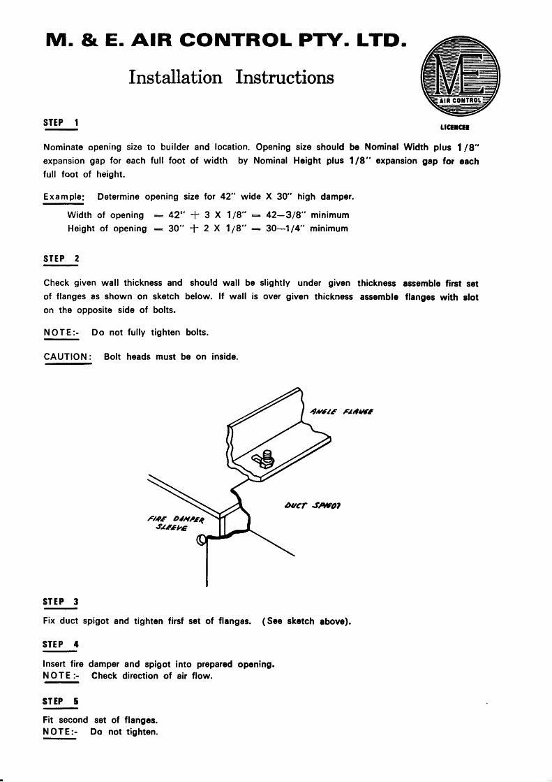
Installation Instructions
STEP I LICETCtT
to builder and location. Opening size should be Nominal Width plus 1 18"fulf foot of width by Nominal Hcight plus 118" expansion gap for each
Exampfe; Determine opening size for 42" wide X 30" high damper.
42" * 3 X 1/8"30" + 2 X 7 /8"
should wall be
below. lf wall is
bolts.
Nominate opening size
expansion gap for each
full foot of height.
Width of openingHeight of opening
S T E P 2
Check given wall thickness and
of flanges as shown on sketch
on the opposite side of bolts.
N O T E :- Do not fully tighten
42-3/8" minimum
30-1 14" minirnum
slightly under given thickness assemble firct setover given thickness assemble flanges with slot
Ftilrc
E
CAUTION: Bolt heads must be on inside.
S T E P 3
Fix duct spigot and tighten firsf set of flanges. ( See sketch above).
STEP 4
lnsert fire damper and spigotN O T E :- Check direction of
STEP 5
into prepared opening.air flow.
Fit secondN O T E : -
set of flanges.Do not tighton.

STEP 6
Fit second duct
CAUTION: Do
STEP 7
Fix damper in open position
NOTE:- On small dampers
spigot and tighten flanges.not fix damper to wall or partition.
Open Fire Damper, reset spring catch and test operate.
STEP 8
Re-open firc damper and reset spring catch to its position prior to operating.CAUTION: Overbending of the spring catch could prevent the damper flrom closing.
STEP 9
with fusible link.
steps 7 to 9 should be done prior to step 3.
STEP IO
Seal duct spigots to fire damper sleeve
NOTE:- See Section thru completed damper installation.
A.v6/ f Fl 4/1/CfS
sE4t oa{slsEkt
F/tf t//r//
l - - n . ,- - - - v .
4/4 F/ou(Fccr,ofrtgzf)
(-\r-
P,tereeprd /4 F/otl)
DAMPER INSTALLATION

0M I Shufier Blade Fire Damper

lur lr Ir.r
,lf ld ew EE
Vlz
*ln

AAAXINAU/I\
TOP
llItilllll
lP*' W I R E
ll-llll
tqE u
roxrJ,
llltl l
llll
I cr pop nrvers +.sr bTOP ONLY
NOTE.COUNTER$JEIGITT I.4K6 .I. SIZE
'lOOr 50 r 3
z. /V\ATER,\AL GALIABO\ID3. FI)(ED ,V'JELIED TO BIADE
Fustgts uHR. BRTDGe73.8'C CENTISRADE
SEE FUII S\7.E DETAIL
50 xa0 x 1 .6 ANG\ES GALTIABONDBOLTED TO BOBY VY\TH
SECTIONj - aOPEN -

llll
illlItil
ItltItll
R,. B.SWt{Ev r{0. SFRTNG. w
SEE DETAIL CFFUSIBLE LINKA\TACI{MEI{T.SECTION A - AAhID RJLL S\7S. bETA\L .
1.o aALvABoNoCRAVIIY DROPI I OFF
EXMNS\O{ GAPTOP t2 MAABOTTq{ l?.iAAAslDEs lz4^l
H\AH 1E^AP I,/\\IERAL WOOLmo'-Ar [q,ou$o

AIR FLO
BRIDGEroo "/ALL
COPPER WIRE TO SUPPORTR,SIBIE LII\K 4BL.ADE.S AALVAIISED
DETAILSI*AT SUPPORT BY RJSIBTE UNK BR\D6E
W

IBU PF^IABAT'JABATAIT BOilBA DAMEIIYEI"AMA:r'uALllYsIA,Head.quuters,Fire qtd Resate Dqarttnertt, Malaysia"Lebuh Wawasan, Precinct 7,
: 603-88880A36139/4O: 603-88880842: ururu.bonba-gou.nq: pr{dfomba-gov.mu
TelefonFacshnileHomepageBmail
NO. RUJUKAN :
NO. SIRI i
TARIKH:
*1.s9Axlf1DIsTl4sle7 lPlol
suIL PEnArrualt BArr,alt 2oo7 l2ooaALI\T KEI,EI{GITNPM
FrRt DAUPEn 4 JAM {TAltPA ITSUT,ASII)
*
Er ! > l
t:,,417,,.!, N:.:*.tr
Jabatan ini memper:akui ALIIT I(ELEIIGKAPAII tersebut di atas berdasarkan Piawaian dffi
ujiannya, dan 'pihak
Arkitek atau Jurutera Profesional bagi projek berkaitan
ritt"rrggurgawab menentukan kesahihan ALI\T I(ELEIIGHAPAIY dipasang mengikut
Piawaian ujiannya (Rujuk pada 1.5 dan 1.6)
1. 1 Nama & Alamit Pengedar : I|AM FOISG (Ul SDIT BIIDlfo. 29, PERSTARATT SEC}AUSUT'SEGAIIBUT TElrcllrr,512OO KI'AI.A LI'UPUR.
1.2 Nama & Alamat Pengeluar : JACKSOII IIITERIIATIOIIAL Pff. LTD'8 Prlrt sTRtEtr,BTDAI,UERE IYSW 2LI6.
: 4 JAM {TAIIPA In$tLllSlD
: o5/04 l2ori7 IIIIIGGA M lo4lzooa
adalahLaporan
l.S No. L,apor:an Ujian/Tarikh : CSIRO g2O & ?2Lz OtIOT | 199)1 e O4lO7lL99LCsIRo FsPo 14{i & 145: otlo7 1L991 & o?lo7 lts:'r
1.3 Tahap Rintangan APi
1.4 Tempoh Sah Perakuan
1.6 Piarvaian
1.7 Spesifikasi
1.8 Keperluan Skim
1.9 Had Kegunaan
csrRo Fsv oaoa 12tll2l2(,o,al(slh temnlatraa Lepq'an U'ren/Assesstnent F qg terliaiortot penbehanraa ot*n datasg. srtfl udak ataadtpecbaharul tanpa dolnrmeo, terrebnrtf
: AS 153O: PART 4z t997 & BS 476t PART 222 L987
: SEPERTIMAISA I"APORAN UJIAII ilODEL 565oF
: SEPERTIMA1YA SPESIFIKASiI UJIAil DAII MEU.,ilTUIII UBBL1984.
2. Lain-lain (nyatakarr) r Sila kemukakan Borang cLl c?l C3 (diisi oleh pihak berkenaan) ke
Jabatan Bomba ian e.nyelamat Negeri di mana projek dijalankan dan lbu Pejabat Bomba dan
Penyelamat, Malaysia apabila selesainya tiap-tiap projek tersebut-
z.l syarat-syarat perakuan Bomba ian nlnyei"m.t ini yang mesti dipatuhi seperti di r.aaplren
al, A2 do,r A3. Spesifikasi ALAT KELE1{GII'aPAII ini adalah-seperti dalarn Laporan ujian (di para
1.5 di atas)
Pembangunan,b. p.
Sila Catatkan No. Rttiufud Kani Apabila Berurusan

IBU PA'ABAT,JAAATAil BOIIBA DAil PII{YELAUAT,UALAYSIA,Heodquarters,Fire and Resate Depaftmart, Malagsia,Lebuh Wawasan, Precinct 7
: 603-888800s6/39/40: 603-8888A842: tlutut.bomba-gou.mg: pr{dpomha^gou.nA
TelefonFaximileHom.epageEmail
NO. RUJUKAN :NO. SIRI :
1.5 Tempoh Sah Perakuan
1.6 No. Laporan Ujian/Tarikh
1.7 Piawaian
1.8 Spesifikasi / Jenama
JPBrr PPP/oo5/33/ 1 | 161ArlrD/8sl rle4lP14l
S1TL PERAKT'AI| BAIIAIT 2OO7I2OA8AI,AT I{ELEI|GKAPAIY
FIRE DA}IPER
r;(Ir i> tra
Jabatan ini memperakui ALAT KELEIIGKAPAIII tersebut di atas berdasarkan Piawaian?an Laporanrrjiannya, dan Pihak Arkitek atau Jurutera Profesional bagi projek berkaitag .a*"nbertanggungiawab menentukan kesahihan ALAT I(ELEIIGI(APAIiI dipasang mengikut LaporanPiawaian ujiannya {Rujuk pada 1.6 dan 1.2)
1.1 Nama g filamat Pengedar : ltlAt FOIfc (Ml SDIY BHDltlo. 29, PEnSIARAIY SEGAUBUT,SEGAIIBUT TEI{GAII,512OO KUAI.A LI'UPUR.
1.2 Nama & Alamat Pengeluar : osBoRlYE METAL ItD. {ilswl pfr LTD.50 HEIIICOTE ROAI',MOORESAIIK I|.S.W. 2L7o.
1.3 Jenis Alat Kelengkapan : ----
1.4 Tahap Rintangan Api : 4 JAII (TAilP^A,INSULASII
: asl07 l2OoT IIlIfccA O2loT l2AaS
: CSIRO #7 1r�e77l,4g9- lt9T6l,49T 1L9691,49G (19?11, 4its(1984), CSInO FSV O8O8 l2tlL2/2OOO1 & CSIRO FC(}O6231o2lo4l2oo5l
: AS 153O: PART 4: 1975
: M & E { o . M . I l168"C FUSIBT.E IJtfKl
I.9 Skim Persdilan Barangan : ----
1.10 Had Kegunaan : MEMATUHI UBBL 19E4 DAlf SEPERTIU,AIIA SPESIFIKASIUJIA!5.
2 la.in-lain (r5ratakan) : Sila kemukakan Borang C.tl C;2l CB {diisi oleh pihak berkenaan} keJabatan Bomba dan Penyelamat Negeri di mana projek diialankan dan lbu Pejabat Bomba danPenyelaurat, Malaysia apabila selesainya tiaptiap projek tersebut.2.1 Syarat-syarat Per:akuan Bomba dan Penyelamat ini yang mesti dipatuhi seperti di LnoplreaA1' Ail de", A3. Spesifikasi ALAT I(ELEI|GKAPAII ini adalah seperti dalo"' Laporan ujian (di para1.6 di atas)
, Perancangan dan Pembangull€trl,
Penyelamat,
Fenolong KetuaBahagianb.p. KetuaJabatan Bomba
Sila Catatkan No. Rujul<an Kani Apabila Berurusan