1840 &1842 installation & operating instructions for ... · pdf fileinstallation &...
TRANSCRIPT

INSTALLATION & OPERATING INSTRUCTIONS FOR FIREVIEW
™
WOOD-BURNING COOKSTOVES
Important! Read this entire manual before you install or use your new cookstove. To reduce the risk of fire, follow the installation instructions. Failure to follow the instructions may result in property damage, bodily injury or even death.
SAVE THESE INSTRUCTIONS FOR FUTURE REFERENCE.
Handles and controls are hot! Use the tool provided or a fire glove to operate dampers and doors. Do not touch with bare hands – severe burns could result.
Repeated or extended over-firing of this stove is dangerous and will void the warranty.
This stove is designed to be connected to a 6” flue / chimney system. The thermometer on the stove door has been calibrated for approximate oven temperatures. Use the interior oven thermometer provided for accurate readings.
FIREVIEW STOVES are listed to ULC Standards S-627 &
UL 1482 by Warnock Hersey
Professional Services Ltd.
MODELS 1840 &1842
CONTACT LOCAL BUILDING DEPARTMENT AND FIRE AUTHORITIES REGARDING PERMITS REQUIRED, RESTRICTIONS AND INSTALLATION
INSPECTION REQUIREMENTS IN YOUR AREA.
MODEL 1842-G: INSTALLATION MUST CONFORM WITH LOCAL CODES OR, IN THE ABSENCE OF LOCAL CODES, WITH
THE NATIONAL FUEL GAS CODE, ANSI Z223.1/NFPA 54.
3372-12

2
Read these instructions completely. Failure to follow these directions could
create a fire / safety hazard, and could void the warranty on your stove.
HOT WHILE IN OPERATION. KEEP
CHILDREN, CLOTHING AND
FURNITURE AWAY. CONTACT MAY
CAUSE BURNS.
DO NOT USE CHEMICALS OR FLUIDS
TO START THE FIRE.
DO NOT BURN GARBAGE OR
FLAMMABLE FLUIDS.
DO NOT CONNECT STOVE TO ANY AIR
DISTRIBUTION DUCT OR SYSTEM.
DO NOT STORE OR USE GASOLINE OR
OTHER FLAMMABLE VAPORS OR
LIQUIDS IN THE VICINITY OF THIS
STOVE.
Smoke detectors should be installed in the
building which houses the stove, in
accordance with local requirements and
recommendations of fire safety officials.
All openings in the floor under, or walls
behind or beside the stove, must be sealed.
Stove Location - Ensure that curtains and
other flammable materials are not able to
blow over the stove, burners or near the fire
box. This will result in a fire hazard.
Do not place sealed metal or glass containers
in oven or warmers, or on cooking surface.
Do not use aerosol containers near the range
when it is in use.
Grease accumulation is a common cause of
cooking fires. Do not attempt to extinguish a
grease or oil fire with water. Cover grease
fires with baking soda or a pot lid, or
extinguish with an appropriate extinguisher.
Clean the oven compartment on a regular
basis to remove grease build-up. Do not leave
pans containing grease or oil unattended on a
hot cooking surface or in a hot oven.
Do not place foil, pans, cookie sheets or
roasting pans directly on the oven bottom.
The oven rack provided can be set on the
oven bottom.
Plastics: Plastics are vulnerable to heat, although some withstand higher temperatures than others. Keep plastics away from parts of the stove which may become warm when the stove is in use.
Surface Cooking: Boil-over or boil-dry conditions could result in a fire. Do not use glass or glazed ceramic cookware on surface burners or cookplates - sudden changes in temperature may break them. Turn handles of pans toward the center of the cooktop, without extending over nearby burners or cookplates. This will reduce the possibility of accidentally overturning the pan. Let hot pans cool in a safe place out of the reach of young children. Never set hot pots on a combustible surface.
Frying: Use as little oil as possible. Filling a pan too full of oil can cause spillovers when food is added. Foods for frying should be as dry as possible. Frost on frozen foods or moisture on fresh foods can cause hot oil to bubble up. Spillovers, fire and burns from splatters could result. Use a deep fat thermometer to prevent overheating oil beyond smoking point.
Deep Frying: Use extreme caution when moving grease kettles or disposing of hot grease.
IMPORTANT: Once per week (more often if using the stove continually), check the channel around the oven for soot and creosote buildup. Clean the channel thoroughly (top, side and bottom) with the tool provided. To reduce creosote build-up, burn the stove hot at least once for every 16 to 24 hours of burning time. Use only seasoned dry wood. Failure to follow
these directions could result in a chimney fire
and will void your warranty.
General Safety
SAFETY INSTRUCTIONS
Woodstove Safety
GAS MODEL 1842-G: See
important safety instructions, Page 3.

3
Have the chimney inspected and
cleaned on a regular basis. A chimney
fire is a safety hazard. In the event of a
chimney fire: 1. Close all combustion air dampers on the
stove immediately. 2. Close the oven damper to restrict the flow of
heat up the chimney. 3. Immediately call the fire department. 4. Prepare to get everyone out of the house in
case the fire spreads. 5. Go outside and check to ensure that hot
ashes do not ignite shingles or other nearby combustibles.
6. Once the fire has burned out and the chimney has cooled, have the chimney inspected to determine if any damage was sustained.
Over-Firing — Caution! Over-firing of a
wood-burning appliance represents a serious
fire hazard. Over-firing can warp your stove,
break welds, discolor plating and cause
premature burnout of your stove. Repeated or
extended over-firings will void the warranty of
this appliance. To prevent over-firing:
If dampering the air intakes has little or no effect on the fire (watch through the Fireview door), the probable cause is excessive chimney draft, especially on chimneys taller than 20’. (Normal chimney draft should be approximately 0.05” Water Column.) In such cases, you will need to install a damper in the stove pipe approximately five feet from the floor. NOTE: To prevent smoking / back-puffing, open oven damper before opening the cook plate or Fireview door.
Install a magnetic thermometer on the top of your stove near the flue collar, or a probe thermometer in the stove pipe. To prevent
creosote buildup in the pipes, the stove
should be run between 800°F and 900°F for
30-45 minutes each burning day.
Except for five to ten minutes after lighting, do not operate the stove with doors open.
Close the ash door and Fireview door during operation. An open door can cause over-firing by allowing excessive draft through the firebox.
Have your chimney cleaned regularly. This will remove excessive creosote buildup.
If any parts of the stove or chimney system begin to glow during operation, the stove is over-fired. Do not add fuel. Close all doors, dampers and draft controls completely until glowing is eliminated and safe temperatures are restored. If over-firing conditions persist on subsequent burnings, contact your dealer for remedial action.
This appliance can be connected to a
standard 20-pound “barbecue” tank, if
done so in accordance with the
instructions below. (Tanks must be located outside of the building. Connection hardware is readily available from your local hardware store or gas technician.)
PROPANE SUPPLY TANKS MUST
BE LOCATED OUTSIDE OF THE
HOUSE. Hoses and connections must
be located and routed to the right side
of the stove, well away from the
firebox and cooktop.
Gas Appliance Safety
(Model 1842-G)
This appliance and its individual shutoff
valve must be disconnected from the gas
supply piping system during any
pressure testing of that system at test
pressures in excess of 1/2 psi (3.5 kPa).
The maximum gas supply pressure is 10
inches water column (2.5 kPa).
Gas supply pressure for checking the
regulator setting shall be at least 11 inch
water column (2.74 kPa).
The maximum allowable depth of
cabinets installed above cooking tops is
13 inches (330 mm).
Leak testing of this appliance shall be
conducted according to the
manufacturer's instructions (page 11).
For safety reasons, top burner flame size
should be adjusted so it does not extend
beyond the edge of the cooking utensil.

4
If you smell gas: Turn off the gas supply to the stove and
call a qualified serviceman. Do not try to light any appliance. Do not touch any electrical switch; do
not use any phone in your building. Immediately call your gas supplier from
a neighbor’s phone. Follow the gas supplier’s instructions.
If you cannot reach your gas supplier, call the fire department.
Installation and service must be performed by a qualified installer, service agency or gas supplier.
If this is a new installation, your installer has not done a proper job of checking for leaks. Connections can loosen in transportation. If the range connections are not perfectly tight, you can have a small leak and therefore a faint gas smell. Finding a gas leak is not a “do-it-yourself”
procedure. Some leaks can only be found with the controls in the “on” position, exposing the user to serious burns. Never use a flame to locate a leak. Do not use gas burners as a heater.
Prolonged use of the gas burners without adequate ventilation can be hazardous. Top burners are not designed for home heating and component failures that may result from such abuse are not covered by the warranty.
Gas Burners: Use proper pan size. Select pans large enough to cover the burner. The use of undersized pans will expose a portion of the burner which may result in burns, ignition of clothing or spillovers directly on burner. Never leave gas burners unattended at high heat setting. Always turn off burners before removing pans.
WARNING: This product must be installed by a licensed plumber or gas fitter when installed within
the Commonwealth of Massachusetts. 1. This installation must conform to local codes
and ordinances. In the absence of local codes, installations must conform to American National Standard, National Fuel Gas Code ANSI Z223.1–latest edition (**) or CSA-B149–latest edition (***) installation codes.
2. Input ratings shown on the serial/rating plate are for elevations up to 2000 feet (609.6 m). For elevations above 2000 feet (609.6 m) ratings are reduced at a rate of 4% for each 1000 feet (304.8 m) above sea level.
In Canada, the installation of this stove must conform to the current standards CSA-Z240–latest edition*** and to local codes. Copies of the standards listed may be obtained from: * National Fire Protection Association, Batterymarch Park, Quincy, Massachusetts 02269 *** Canadian Standard Association, 178 Rexdale Boulevard, Rexdale (Toronto), Ontario M9W 1R3
Use of High Flame: When using a high flame, never leave any pans unattended. Hot oil is particularly hazardous, since it can become hot enough to ignite.
Venting: Do not obstruct the flow of combustion and ventilation air to the stove. Any openings in the wall behind the stove or the floor under the stove must be sealed. Never block the air openings of the gas burner compartment. They provide air inlet which is necessary for proper combustion.
Type of Gas: Liquid Propane (LP) gas. Stoves are factory assembled for liquid propane gas. Burners are rated for 11,000 BTU’s each, based on Liquid Propane.
5
Safety Instructions General Safety 2
Woodstove Safety 2
Gas Appliance Safety (Model 1842-G) 3
Getting Acquainted 6
Unpacking & Assembly 6 Removing & Replacing Firebrick & Grate 7 Removing Stove from Skid 7 Assembly 7 Flue Boot Assembly 7 Cabinet Assembly 7 Pipe Damper Installation 8
Installation 8 Clearances & Heat Shields: 9
Reducing Clearances 9 Floor Protection 9 Gas Installation: 10
Gas Supplies 10 Gas Piping to Stove 10 Manual Shutoff 11 Pressure Testing 11 Gas Leak Testing 11
Chart of Clearances 12
Optional Heat Shield Kit 13
Rough-in Diagrams & Dimensions 15
Wood-Burning Basics 16 The Chimney 16 Air Intakes 16 Dampers 16 Fireview Door 16 Wood 17 Firebox 17
Chimney Requirements / Installation 18 Existing Chimneys 18 Flue Pipes 18 Stovepipe-to-Chimney Connection 19 Connecting to Pre-Fabricated Chimney 19 Chimney Connection Systems – Thimbles 21 Chimney Clearances 22
Chimney Function & Draft: 22 Chimney Height 22 Cold or Over-Sized Flue or Liner 22 “Stack Effect” & Negative Pressure 22
Operating Your Fireview Stove 23 Break-in Fire 23
Starting a Fire 24
Maintaining a Fire 24 Disposing of Ashes 25
Cooking: 26 Stove Top Cooking: 26
Cooktop Guidelines, Instructions & Tips 26 Oven Cooking: 27
Door Thermometer Calibration 28 Warmers 28
Gas Burner Operation: 29
Igniting Gas Burners 29
Trouble-Shooting 29
Maintenance & Adjustments 32 Oven Flue Passage – Cleaning 32 Flue Boot 32
Oven Damper 32
Chimney 32
Chimney Cleaning 33
Cookplates 33
Gas Burner Cleaning 33
Manual Burner Adjustment on Low 34 Fireview Glass Cleaning / Replacement 34
Igniter Battery 35
Porcelain / Powder Coated Finishes 35
Nickel Trim 35
Oven Compartment 35 Door Gaskets 35
Firebox 35 Removing & Replacing Firebrick & Grate 36
Glossary of Terms 37
Parts of Your Fireview (Diagram) 38 Fireview Parts (List) 39
Options & Accessories 40 Heat Shield Kit 40
Warranty 41
Contents

6
Your FIREVIEW™ cookstove is the result of thirty-five years of experience designing and manufacturing spectacular high-quality wood-burning stoves and kitchen appliances. It is a true original, based on authentic designs and castings from antique stoves, but with many modern conveniences and efficiencies. With proper operation and maintenance, your FIREVIEW will give you and your family years of cooking pleasure, wonderful meals and warm memories. Operating and cooking on a wood-burning
cookstove is part science, part art. We are
confident you will enjoy the learning experience
and the sense of accomplishment as you master
the art of woodstove cooking. Begin by thoroughly reading this manual to gain a basic understanding of your stove’s operation. As you gain experience, your skill will increase, as will the quality of your results. Please take the time to read this manual thoroughly so that you can become familiar and comfortable with proper installation, operation and maintenance procedures for your appliance. Familiarize yourself with your stove with a few “test runs” on a cold stove. Operate the various controls. Then burn a low fire for a few hours, taking the time to see how the controls affect the flame, oven temperature, cooktop and warmers, etc. After you have used your stove for a few weeks, re-read the appropriate portions of this manual. Some procedures that seemed confusing on first reading will become clear once you have used the stove.
This owner’s manual is an important tool, and should be kept near the stove for reference. If you sell your stove, pass the manual along to the new owner, so that they too can enjoy the full benefits of this appliance. The performance of your stove will be directly affected not only by how you operate it, but also by the quality of materials and workmanship used in its installation (especially the chimney and connections), and the quality of wood you burn. More information on these topics is provided in this manual. Through experience, you will learn the role the dampers and chimney play in your stove’s performance. The Fireview has been tested by Intertek Warnock Hersey and is listed by Underwriters’ Laboratories of Canada (Standard ULC S-627) and Underwriters’ Laboratories in the U.S. (Standard UL 1482). This stove is listed for burning wood. Do not burn other fuels; doing so may be dangerous and will void your warranty. The Fireview is not listed for installation in, and must not be installed in, mobile homes. Safety Notice: A house fire could result if your
stove is not properly installed and maintained. It is
important for your safety that you follow all
instructions for installation, operation and
maintenance. Contact your local building officials
regarding restrictions and inspection requirements
in your area. Failure to comply with these
instructions, restrictions, requirements and codes
is dangerous and could be unlawful.
Understand local building codes, restrictions and inspection requirements prior to installing your stove. Clear the area where the stove will be located so you will have room to work and will only have to move the stove once. You will need a Phillips or red-handled square screwdriver, 7/16” wrench, 7/16” socket wrench and pliers. The stove is packed as follows: Stove - bolted to the skid Flue boot assembly - screwed to skid Boxed upper cabinet - strapped to the cooktop Cookplates / wood grate - shipped in place
Firebrick - in a box in the firebox Ash pan - behind the ash door (bottom left) Ash tool - taped beneath the cookplates. Manual / flue boot insulation - in the oven A package in the ash pan contains: o Tool for opening dampers / doors o Cookplate lift handle with bolt and nut o Four cabinet bolts & nuts o Interior oven thermometer o Rear brick bracket o Six nuts and washers for flue boot
Getting Acquainted With Your Fireview™ Cookstove
Unpacking & Assembly

7
1. Remove plastic from box(es) on cooktop. 2. Remove heat shield (if ordered) and cabinet box
from cooktop. 3. Remove shrink wrap from rest of stove. 4. Remove ash pan from behind ash door. 5. Remove cookplates: Open Fireview door and
push up on left plate. Grasp plate from above and remove. Lift and remove remaining plate(s).
6. Remove ash tool taped to top of oven compartment.
7. Remove firebrick from firebox: Open corrugated box. Remove bricks, starting with smallest bricks first. Set aside, standing on edge. Remove box from firebox.
8. Remove flue boot from skid using screwdriver. 9. Unfasten two nuts and bolts holding the stove to
the skid, using two 7/16” wrenches (a socket wrench is very helpful). Wear gloves to protect against cuts. Lift the stove off the skid and set on the floor. Warning: If you have not removed all removable parts, the stove is very heavy. Do not slide or set stove on soft flooring, as this could permanently damage the floor.
10. Optional: Remove doors / ash catch: Using pliers, remove retainers from bottom of fire and ash door hinge pins. Lift and remove all three doors. Remove four screw holding side warmer door in place. Remove screws holding ash catch in place. Replace doors, screws and retainers after installation.
If you remove all items noted above, the stove weighs about 150 pounds and can be lifted by two people; otherwise you may need three people – two on the firebox side and one on the oven side. If you are working in tight quarters, have another person slide the skid out from under the stove.
We recommend you assemble your stove and chimney in the following order: 1. Flue boot assembly (below) 2. Stove / flue boot heat shields (optional -page 14) 3. Stove pipe / chimney 4. Pipe heat shield (optional – page 13) 5. Firebrick (page 35)
6. Cookplates – install right and center plates first (radiused edge on bottom to front of stove), then follow instructions for installing left plate and lift handle (see “Cabinet Assembly”). (Center plate has no reinforcing bar.)
As you are facing the stove from the back, attach the flue as follows: 1. Remove protective paper from tape on edge of
flue boot. Attach felt insulation strips (shipped in oven) to flange on flue boot, ensuring entire edge of boot is covered.
2. Remove three (3) screws from the stove body below the lower flue opening.
3. Slip the boot over the damper rod and onto the six bolts on the stove back. Fit the square tube into the hole. Cut out insulation to clear tube.
4. Install and tighten six washers and nuts found in the hardware package in the ash pan.
5. Replace and tighten three bottom screws.
Never attempt to move the stove by holding the
cabinet or trim around the cooking surface. Carefully unpack the cabinet. 1. From the back of the stove, have two people lift
the cabinet into place on the stove. Align the holes in the bases of the cabinet brackets with the holes in the left and right side trim rails.
2. While one person steadies the cabinet the other will drop the three bolts provided through the
Removing Stove from Skid
Cabinet Assembly
Flue Boot Assembly
Assembly

8
holes in the left side of the bracket and the rear hole of the right bracket. Position the cabinet as far back on the stove as the bolt holes will allow, leaving a slight air space between the cooktop and splashback. Attach locknuts to the bolts and tighten.
3. Screw the bolt through the front hole in the right bracket into the threaded hole in the trim rail.
4. Insert the lift handle through the left bracket. Bolt it to the left cook plate using the bolt and nut provided. The handle should pivot freely so it can be swung in and out of the stops on the left cabinet bracket. Tighten the nut securely so it will not work free during normal use.
5. Remove the three 2” bolts fastened inside the cabinet and re-install the bolts on the outside back of the cabinet. Hang the ash tool and damper tool on these bolts.
A pipe damper is optional and should only be required if the top of the chimney is more than 20’ above the top of the stove. If required, damper installation should be completed prior to final assembly of the chimney. If you are using single-wall pipe, your dealer can supply and install a damper. The damper should be installed 6 – 12” above the top of the upper cabinet. 1. Drill a ¼“ hole through the middle front of pipe. 2. To mark the location for the damper hole in the
back of the pipe, push the sharp end of the damper rod into the back wall of the pipe. Drill a ¼” hole through the back of the pipe.
3. Follow the instructions supplied with the damper and install the damper inside the pipe with the handle facing the front of the pipe.
4. Ensure the damper rotates freely in the pipe. If you are using double-wall pipe, your dealer can supply a pipe section with a damper pre-installed.
(See page 15 “Rough-in Diagrams & Dimensions”)
Important! Read this entire manual
before you install and use your new
cookstove. If this stove is not properly
installed, a house fire may result. To
reduce the risk of fire, follow the
installation instructions. Failure to follow
the instructions may result in property
damage, bodily injury or even death. The
authority having jurisdiction (building
department or fire authorities) should be
Pipe Damper
Installation
9
consulted before installation to determine
the need to obtain a permit.
NOTE: Read the sections on clearances, floor protection and chimneys before you begin installation. Follow building codes, installation requirements and restrictions in your area. Contact
your local building or fire officials if you have
any questions or concerns.
Seal all holes in walls and floors near the stove. Preparing the area in which the stove will be located will save you from having to move the stove more than once. Refer to the sections on Clearances and Floor Protection in this manual.
Dual Fuel Model 1842-G: Installation, adjustment and service must be performed by a qualified gas installer.
Wood-burning appliances and chimneys radiate heat in all directions. Heat radiated towards nearby walls, floors, ceilings and furnishings can cause a fire hazard if proper clearances and shielding are not provided. Clearances are distances that must be maintained between hot stove and chimney parts and nearby combustible materials – the greater the distance, the more the air will cool before contacting combustibles. Cool air circulating between the stove and surrounding materials carries heat away and eliminates the risk of combustion. Nothing other than non-combustible heat shields should be placed in the clearance area. Do not put insulation in the clearance area between the stove and heat shield or between the heat shield and walls. Do not store fire wood in the clearance area. As wood dries, the temperature at which it will ignite decreases. This cookstove has been tested and certified for safe operation, providing these guidelines are followed. Clearances listed in this manual must be
maintained to all combustible materials; including
doors, trim, furniture, decorations, drapes, fabric,
boxes, paper, etc.
Heat shields can be used to reduce rear clearances (chart page 12.). The shield mounts on the back of your stove and flue boot. The upper section covers
the flue pipe from the flue boot to the top of the cabinet; the main section covers the stove body and flue boot. Instructions are included with the shield. Reducing Clearances Many decorative alternatives are available to reduce clearances to combustibles. Contact your dealer and / or local fire and building officials to ensure these alternatives meet applicable standards in your area. In the United States refer to National Fire
Protection Association Standard 211. In Canada refer to the Installation Code for Solid Fuel
Appliances and Equipment (CAN3-B365-M84).
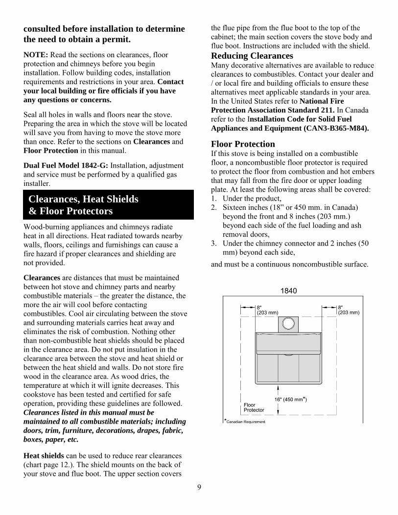
Floor Protection If this stove is being installed on a combustible floor, a noncombustible floor protector is required to protect the floor from combustion and hot embers that may fall from the fire door or upper loading plate. At least the following areas shall be covered: 1. Under the product, 2. Sixteen inches (18” or 450 mm. in Canada)
beyond the front and 8 inches (203 mm.) beyond each side of the fuel loading and ash removal doors,
3. Under the chimney connector and 2 inches (50 mm) beyond each side,
and must be a continuous noncombustible surface.
Clearances, Heat Shields
& Floor Protectors

10
The thermal insulating layer must have an R-
value of 0.60 or greater and must be covered by non-combustible material such as metal, tile, stone, etc. Sheet metal pads and grouted ceramic floor tiles are acceptable floor protection. To determine if a proposed alternate floor protector meets these requirements, follow this procedure: 1) Convert specification to R-value:
i If R-value is given - no conversion is needed.
ii If k-factor is given with a required thickness (T) in inches: R = 1/k x T
iii If C-factor is given: R = 1/C
2) Determine the R-value of the proposed alternate floor protector. i Use the formula in step (1) to convert values
not expressed as "R". ii For multiple layers, add R-values of each
layer to determine the overall R-value.
3) If the overall R-value of the system is greater than the R-value of the specified floor protector, the alternate is acceptable.
Example: The specified floor protector should have an R-
value of 0.60 The proposed alternate is 4" brick with a C-
factor of 1.25 over 1/8" mineral board with a k-factor of 0.29.
Step (a): Calculate R of proposed system.
4" brick of C = 1.25, therefore Rbrick = 1/C = 1/1.25 = 0.80 1/8" mineral board of k = 0.29, therefore Rmin.bd. = 1/0.29 x 0.125 = 0.431 Total R = Rbrick + Rmineral board = 0.8 + 0.431 = 1.231
Step (b): Compare proposed system R of 1.231 to specified R of 0.60. Since proposed system R is greater than required, the system is acceptable.
Definitions:
Thermal conductance = C = Btu = W
(hr)(ft²)(ºF) m²)(ºK) Thermal conductivity = k = (Btu)(inch) = W = _Btu
(hr)(ft²)(ºF) (m)(ºK) (hr)(ft)(ºF)
Thermal resistance = R = (ft²)(hr)(ºF) = (m²)(ºK) Btu W
This stove can be connected to a standard 20-
pound “barbecue” tank, if all requirements
listed below and in the safety instructions on
page 3 are met. Connection hardware can be
purchased from a local hardware or barbecue
retailer. The propane tank must be located
outside of the building. When installing a Model 1842-G dual fuel (wood and propane) stove, the installation must comply with all codes and standards for both wood-burning and gas appliances. If codes or requirements vary between the two standards, the more stringent restrictions must be observed.
Gas Supplies Before connecting to the supply systems, be sure that the installation conforms with the local codes or, in the absence of local codes, with the National Fuel Code, ANSI Z223.1 latest edition or CSA-B149 installation codes.
Gas Installation (Model 1842-G)

11
Gas Piping to Stove With liquid propane gas, the size of the piping to the stove is determined by the length of the run form the supply to the stove, and should be determined by your gas fitter. When connecting pipe to the die cast regulator, use two wrenches. Excess pressure or tightening the pipe too tight can cause the regulator to crack, resulting in a gas leak or a possible fire or explosion. Make sure if flexible connectors are used in connecting the appliance to the gas supply, they are CSA approved. Poorly designed connectors can be a source of gas leaks. Even if CSA approved flexible connectors are used, the customer should be cautioned against kinking or damaging the connection when moving or cleaning the range. This could cause a gas leak. Suitable pipe thread sealant, which is approved for use with liquid propane gas, must be used. Be sure to use this thread sealant on all pipe connections.
Manual Shutoff Install a manual shutoff valve in the gas line in an accessible location near the unit. Know where the gas valve is so you can shut off the gas to the stove quickly.
Pressure Testing The appliance and its individual shutoff valve must be disconnected from the gas supply piping system during any pressure testing of the system at test pressures in excess of 1/3 psig (3.5kPa). The appliance must be isolated from the gas supply piping system by closing its individual manual shutoff valve during any pressure testing of the gas
supply system at test pressures equal to or less than 1/2 psig (3.5kPa). The gas supply pressure for checking the regulator setting shall be at least eleven inches water column.
Gas Leak Testing After the final gas connection has been made, the burner valves should be closed and the gas supply and manual shutoff turned on. All connections in the gas supply line and in the range should be tested with soap suds or an electronic “sniffer” for leaks. Detecting a leak:
If a leak is present, bubbles will appear. If you
detect a leak, follow these directions:
Shut off the gas supply before attempting to fix the leak. The leak should be stopped by tightening the joint or unscrewing completely and applying additional pipe dope and re-tightening. Turn the gas supply on and re-test. Any factory connections which may have been disturbed should be retested. A match should never be used when testing for
leaks. All fittings have been tightened and tested
at the factory. If a leak is detected, tighten the
fitting. Don’t use pipe dope on factory fittings.
Gas Burner / Grate Installation: Place caps on burner bases so tabs on caps fit into grooves. Place grates over burners with flat edge of grate matching flat edge of burner base.

12
The following clearances must be observed. If two or more clearances to combustibles contradict each other, the greater distance applies and must be maintained. Model 1842-G: Observe all instructions on the gas appliance rating plate for minimum clearances to any adjacent vertical combustible surfaces. Gas ranges require a CSA approved stainless steel gas flex line or flexible copper coil ½” in diameter and at least three feet long so the stove can be moved for service.
MODEL 1840 A B C E F G H J Measure
No Heat Shield Using Single Wall Pipe
10 18 13 18 18 60 18 48 Inches
254 457 330 457 457 1524 457 1219 Mm.
With Heat Shield Using Double Wall Pipe
10 3 10 6 6 60 18 48 Inches
254 76 254 152 152 1524 457 1219 Mm.
MODEL 1842
No Heat Shield Using Single Wall Pipe
3 18 13 18 18 60 18 48 Inches
76 457 330 457 457 1524 457 1219 Mm.
With Heat Shield Using Double Wall Pipe
3 3 10 6 6 60 18 48 Inches
76 76 254 152 152 1524 457 1219 Mm.
G = vertical distance from cooking surface to combustibles above the stove. Note: A certified double-wall stove pipe must be used to maintain 6” clearance (dimension E) from pipe to combustibles. The approved stove pipe must extend from the chimney to the stove. Note: These are factory-recommended clearances. Local, state or provincial building and fire codes take precedence and must be observed. Clearances are subject to change without notice. When heat shield is installed, dimensions B and F are taken from heat shield. (“Heat shield” refers to complete stove/-pipe shield kit.) Dimension E is taken from outside edge of pipe.
Chart of Clearances
13
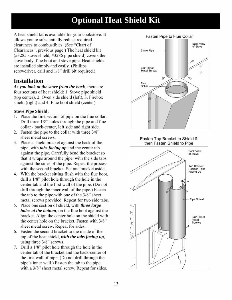
A heat shield kit is available for your cookstove. It allows you to substantially reduce required clearances to combustibles. (See “Chart of Clearances”, previous page.) The heat shield kit (#3285 stove shield, #3286 pipe shield) covers the stove body, flue boot and stove pipe. Heat shields are installed simply and easily. (Phillips screwdriver, drill and 1/8” drill bit required.)
Installation As you look at the stove from the back, there are four sections of heat shield: 1. Stove pipe shield (top center), 2. Oven side shield (left), 3. Firebox shield (right) and 4. Flue boot shield (center) Stove Pipe Shield:
1. Place the first section of pipe on the flue collar. Drill three 1/8” holes through the pipe and flue collar - back-center, left side and right side.
2. Fasten the pipe to the collar with three 3/8” sheet metal screws.
3. Place a shield bracket against the back of the pipe, with tabs facing up and the center tab against the pipe. Carefully bend the bracket so that it wraps around the pipe, with the side tabs against the sides of the pipe. Repeat the process with the second bracket. Set one bracket aside.
4. With the bracket sitting flush with the flue boot, drill a 1/8” pilot hole through the hole in the center tab and the first wall of the pipe. (Do not drill through the inner wall of the pipe.) Fasten the tab to the pipe with one of the 3/8” sheet metal screws provided. Repeat for two side tabs.
5. Place one section of shield, with three large
holes at the bottom, on the flue boot against the bracket. Align the center hole on the shield with the center hole on the bracket. Fasten with 3/8” sheet metal screw. Repeat for sides.
6. Fasten the second bracket to the inside of the top of the heat shield, with the tabs facing up, using three 3/8” screws.
7. Drill a 1/8” pilot hole through the hole in the center tab of the bracket and the back-center of the first wall of pipe. (Do not drill through the pipe’s inner wall.) Fasten the tab to the pipe with a 3/8” sheet metal screw. Repeat for sides.
Optional Heat Shield Kit
14
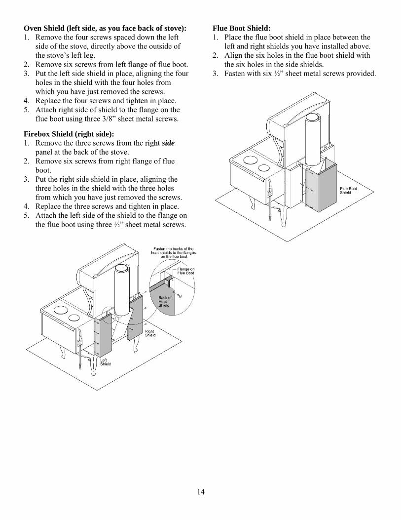
Oven Shield (left side, as you face back of stove):
1. Remove the four screws spaced down the left side of the stove, directly above the outside of the stove’s left leg.
2. Remove six screws from left flange of flue boot. 3. Put the left side shield in place, aligning the four
holes in the shield with the four holes from which you have just removed the screws.
4. Replace the four screws and tighten in place. 5. Attach right side of shield to the flange on the
flue boot using three 3/8” sheet metal screws. Firebox Shield (right side):
1. Remove the three screws from the right side panel at the back of the stove.
2. Remove six screws from right flange of flue boot.
3. Put the right side shield in place, aligning the three holes in the shield with the three holes from which you have just removed the screws.
4. Replace the three screws and tighten in place. 5. Attach the left side of the shield to the flange on
the flue boot using three ½” sheet metal screws.
Flue Boot Shield:
1. Place the flue boot shield in place between the left and right shields you have installed above.
2. Align the six holes in the flue boot shield with the six holes in the side shields.
3. Fasten with six ½” sheet metal screws provided.

15
Drawings and dimensions provided for reference only, showing approximate dimensions for rough-in purposes. Ensure
that no ceiling or floor supports will be cut or compromised for chimney installation.
Rough-in Diagrams & Dimensions
1842
1840
1840/
1842
16
A wood-burning cookstove is a unique appliance. The chimney, air intakes, dampers, Fireview door, wood and firebox all work together as one system to determine how efficiently and long your fire will burn, and how temperatures will be distributed throughout the cooking surface oven and warmers.
The Chimney The chimney is more than a pipe which allows smoke to escape. The height of your chimney and the resulting pressure difference between the stove and the top of the chimney outside your home create “draft” – a natural flow of air from the room, through the stove and up the chimney. Draft provides oxygen for combustion. The chimney is the most important component in the operation of your stove. If it is blocked, if air movement is impeded by structures near the top of the chimney, if it is too large in diameter, or if the “stack” is not high enough, it will be difficult or impossible to obtain the draft needed for a good fire.
Air Intakes Draft from the chimney will draw air into the firebox from a number of sources: “Primary” combustion air enters through two
slide dampers located on the left side of the firebox. This is the main (“primary”) source of air for the ongoing operation of your stove.
“Secondary air” is drawn through a tube entering the top of the firebox at the back of the stove. Once your firebox gets up to operating temperature, this secondary air re-ignites smoke and gases above the wood. This provides additional heat and results in greater efficiency, longer fires, less creosote build-up, and a very clean burn. The secondary air also provides a “wash” over the glass of your Fireview door to reduce smoke build-up on the glass.
“Start-up air” - When starting a fire, or adding heavy logs, you will want to open the ash door (located below the Fireview door) slightly, to allow more air into the firebox. This additional air will help the new wood ignite faster, getting or returning the firebox to high temperatures. The ash door must be closed after the fire is
established – not more than fifteen minutes
after lighting.
Dampers Your Fireview range features two types of dampers: 1. An oven slide damper located at the back left
side of the cooktop. This damper controls how much of the heat generated in the firebox goes directly up the chimney, and how much is diverted to heat the oven. When you are first starting your stove, you will want air to flow freely up the chimney for maximum draft. As the fire is established, you can close down the oven damper to provide heat to the oven and to reduce the speed at which your wood burns. Proper operation of the oven damper is discussed on Page 27 – “Oven Cooking”.
2. Two stainless steel tubular slide dampers, located on the left side of the firebox. These innovative dampers slide horizontally and control the amount of air the chimney is allowed to draw through the firebox. One damper is located below the grate in the firebox, providing maximum draft through the fire wood. The other is located just above the grate, providing additional combustion air. The design of these dampers allows precise control of air flow. When you first start a fire, both of these dampers should be in the “full open” position (pushed to the back) to provide maximum air flow through the fire wood. As the fire establishes itself, adjust the dampers to control oven, cooktop and room temperatures, and the burn rate of your fire. By looking through the Fireview door as you adjust the dampers, you will learn how these dampers control your fire.
Fireview Door The obvious function of the Fireview door is to allow you to see and enjoy your fire. The less obvious function is to allow you to conveniently monitor and adjust the fire without opening a door or cook plate and letting heat escape. You will quickly learn how the dampers affect stove operation, when and how to adjust the dampers, and when to add wood to a dying fire. Warnings:
Avoid operating the stove in a manner that will result in breakage or cracking of the Fireview
Wood-Burning Basics

17
glass. – striking or slamming the door or glass, splashing liquids on hot glass, etc.
Clean glass with low alkaline content commercial stove glass cleaners, available from your dealer.
Do not clean the glass when hot. Do not clean with abrasive cleansers.
Do not operate the stove with a broken or cracked Fireview glass.
Replace glass only with glass supplied from the manufacturer or distributor of this appliance. See “Fireview Glass Cleaning & Replacement”, page 34.
Wood Wood is the fuel that drives your fire. Often forgotten or overlooked is the fact that the performance of the stove is directly related to the quality of the fuel. Just as you wouldn’t expect to run a high-performance car on low-octane gasoline, you should not run your Fireview stove on wet “punky” wood. The best and most satisfying performance of your Fireview stove will be achieved by burning high-quality hardwoods that have been split, stacked and “seasoned” under cover and out of precipitation for at least a full year. Burning wet, damp, inadequately seasoned wood will yield steaming, sizzling fires, excessive smoke, low heat output and excessive and dangerous build-up of soot and creosote. This can lead to deterioration of your stove and chimney, and to fire hazards. Do not burn skids, pressure treated, painted or lacquered wood, saltwater driftwood, or any materials other than wood. Use of improper fuels can damage your stove, cause safety and health hazards, and void your warranty. The Fire in Firewood – 3 Elements of Firewood
Three elements of firewood enhance or inhibit proper burning – water, smoke/ gases, and charcoal. 1. Water: When fire wood is first cut, over half of
the content is water. After a year of seasoning, as noted above, more than 60% of this moisture will evaporate, leaving dry wood that is ready to provide good clean heat. Heat energy is required to evaporate moisture, so burning damp wood will result in sluggish, hissing low fires that produce little heat and are difficult to sustain.
2. Smoke & Gases: As the wood in your fire dries out, less energy is being used to evaporate water
in the wood and more energy is being used to create heat. As the temperature of the wood increases, the wood will begin to smoke, releasing hydrocarbon gases and tars. When these combustible gases combine with oxygen and high temperatures, combustion occurs, further raising the temperature and creating more gases. When the temperature becomes high enough, there will be two fires in the firebox – the main fire in and around the logs, and the “secondary” burn above the main fire. This represents a clean, efficient burn. Smoke and gases make up about half of the heat energy in your firewood.
3. Charcoal: When most of the gases in the wood have vaporized, the remaining charcoal will combine with oxygen for a hot, steady fire that emits consistent heat and very little smoke or flame. Charcoal makes up approximately half of the heat energy in your wood.
Firebox The firebox of your Fireview wood-burning cookstove is a state-of-the-art apparatus that has been engineered to provide high output, high efficiency, and long life. It is the most advanced firebox available on any wood-burning cookstove. With its large (1.6 cubic foot) capacity, the firebox will provide up to 60,000 BTU’s of heat per hour, and its 21” depth will easily accommodate 18” logs. The bottom of the firebox houses a heavy-duty steel wood grate. This grate holds the wood and has many holes, allowing combustion air to pass up through the wood, and ash to fall into the ash bin below for removal. As noted above, the Fireview’s firebox incorporates many unique features - the viewing door, secondary air supply and exclusive tubular slide dampers. The firebox is lined with “fire brick” that has been specifically designed for the Fireview. The brick is reinforced with stainless steel strands to resist cracking and breaking, and is pre-fired before installation to minimize the need for “break-in”. See “Break-In Fire” on page 23.

18
WARNING: DO NOT CONNECT THIS UNIT
TO A CHIMNEY FLUE SERVING ANOTHER
APPLIANCE. This stove must be connected to 1) a listed 6” Type HT (2100°F) chimney per UL 103 or ULC S629, or 2) a code-approved masonry chimney with a flue liner. The chimney size should not be less than or more than three times greater than the cross-sectional area of the flue collar. Prior to installing your stove into a masonry chimney, have the chimney inspected by a qualified mason. An unlined masonry chimney should not be used – a proper liner should be installed. Connect this stove to a 6” chimney. A larger
chimney will result in poor draft and / or reduced
oven temperatures. The chimney and installation
must be inspected by a local building inspector. Existing Chimneys
If you plan to connect your cookstove to an existing chimney, you should have the chimney thoroughly inspected prior to connection to ensure its suitability for use. This inspection should be performed by an experienced professional. Your retailer can provide this service or refer you to a qualified professional. Masonry chimneys: Existing masonry chimneys must be carefully and completely checked for deterioration, including damaged or deteriorating mortar, cracks in the drip cap, damaged bricks and / or loose flashings where the chimney meets the roof line. The liner should be 6” in diameter and should be inspected for cracks and / or misalignment. A stainless steel liner should be installed if there are cracks in the chimney. A chimney will not draw properly if there are cracks in it. Pre-fabricated metal chimneys: Your stove can be connected to a pre-fabricated chimney approved to ULC Standard S629 in Canada and UL 103HT in the United States. The metal chimney should be inspected for a warped or buckled liner, corrosion of the outer shell, loose flashing and / or lack of proper support. Discoloration of the metal shell near a joint indicates the insulation has settled - the chimney should be replaced to ensure safe and efficient operation.
Flue Pipes
Flue pipes carry exhaust gases from the stove’s flue collar to the chimney. The flue pipe assembly is an extremely important part of a wood-burning system and must be planned and installed carefully. The checklist below is based on requirements found in the Canadian Standards Association’s “Installation Code for Solid Fuel Burning Appliances and Equipment” (Standard B365). It should be followed when installing or inspecting a flue pipe assembly. 1. Single-wall flue pipe assemblies must not
exceed 3 meters (10 feet) in overall length. 2. The assembly should be as short and direct as
possible. 3. A single-wall flue pipe assembly must have no
more than two 90 degree elbows; use 45 degree elbow, wherever possible.
4. Do not use galvanized flue pipe. The coating can vaporize at high temperatures, emitting poisonous gases and leaving the pipe thin and weak.
5. Flue pipes for wood-burning appliances need to be thicker than those used for other fire-burning appliances - 24-gauge for 150 mm (6”).
6. Joints between pipes should overlap at least 30mm. (1-1/4”).
7. Each joint must be secured with three sheet metal screws (except for one expansion joint, if necessary and as noted below).
8. The assembly should be constructed to allow for expansion. Elbows in an assembly allow it to expand. Straight pipe assemblies should have one section left unscrewed and secured with an inspection wrap clamped around the joint.
9. Horizontal pipe should slope up towards the chimney at least 20 mm. per meter (1/4” per ft.).
10. One end of the flue pipe assembly must be securely fastened to the flue collar of the appliance and the other end must be securely fastened to the chimney.
11. There must be provision for cleaning and inspecting pipes by removal of the pipe. Removal of pipes should not require that the appliance be moved.
12. The crimped ends of pipes should point towards the appliance so that condensation drains to the
Chimney Requirements & Installation

19
appliance and does not leak out through the joints between pipe sections.
13. A flue pipe must never pass through a combustible floor or ceiling, concealed attic, roof space or closet.
14. Flue pipe assemblies must be stable and secure. To check its stability, grasp the assembly at its mid-point and shake. If properly constructed, the assembly will have very little movement.
Stovepipe-to-Chimney Connection
1. The pipe-to-chimney connector should be 24 gauge (or thicker) sheet metal and 6” diameter.
2. The section of chimney connector closest to the stove should be screwed to the flue collar of the stove. Individual sections of the chimney connector must be secured with at least three sheet metal screws. The last section of pipe should be securely attached to the chimney. Inspect and correct to ensure there are no weaknesses in the system.
3. Crimped ends of pipe should point downward so that soot, creosote or condensation in the pipe will drop into a clean-out or fall into the stove.
4. The chimney connector should be above the upper cabinet before any elbow is installed. No more than two 90 degree turns should be used.
5. A 6” adjustable pipe damper, installed about six feet above the floor, will allow better control of excess chimney draft on cold, windy days.
6. A horizontal run of stovepipe should be no longer than 4 feet long. A vertical run of pipe to a pre-fabricated metal chimney should be no longer than 8 feet.
7. Do not use single wall smoke pipe as an outside chimney. Creosote will build up quickly in the pipe, leading to a chimney fire.
8. A chimney connector shall not pass through a combustible ceiling, attic, roof space, closet, floor or similar concealed space. Where passage through a wall or partition of combustible construction is desired, the installation shall conform with CSA B365.
9. The entire chimney connector must be exposed and accessible for cleaning and inspection.
10. Galvanized stovepipe should not be used. When exposed to high temperatures, galvanized pipe can release toxic fumes.
11. Horizontal runs of chimney connector should slope upward 1/4” per foot going from the stove toward the chimney.
12. During a chimney fire the chimney connector may vibrate violently. The connector must be securely attached to the pipe and chimney, and individual sections must be securely attached together.
13. Do not connect this stove to an air distribution duct.
Connecting to Pre-Fabricated Chimney:
When connecting your cookstove to a prefabricated metal chimney, you must precisely follow the manufacturer's installation instructions. Use only Type HT (2100 deg. F), prefabricated metal chimneys listed per UL 103 or ULC S629 standards. Make sure the size of the chimney flue is appropriate for the stove. The Fireview requires a 6" (152 mm) inside diameter flue for new installations. A 6” diameter flue provides adequate draft and performance. You can use an 8" (203 mm.) diameter existing flue with a reducer. An oversized flue contributes to creosote accumulation. When purchasing a prefabricated chimney to install with your stove, be sure to also purchase from the same manufacturer, the wall pass-through (or ceiling support package), "T" section package, fire-stops (when needed), insulation shield, roof flashing, chimney cap, and other needed accessories. Follow the manufacturer’s instructions when installing chimney and accessories. In addition, be sure to maintain all manufacturers’ recommendations for proper clearances to the chimney. There are two ways to install a prefabricated metal chimney: An interior installation where the chimney
passes inside the residence through the ceiling and roof.
An exterior installation where the chimney passes through the wall behind the stove then up the outside of the residence.
Whenever possible, choose an interior chimney. An interior chimney heats up more quickly and retains its heat; thus promotes a better draft and discourages the formation of creosote. An exterior chimney does not benefit from the warmth of being surrounded by the building, so it typically operates at lower flue temperatures than an interior chimney. An exterior chimney’s draft is not as strong and may experience increased creosote accumulation.

20
Connections to Pre-Fabricated Metal Chimney:

21
Chimney Connection Systems – Thimbles (Wall Penetration Assemblies): Use one of these connection methods when the connection from the stove to the chimney is made through a combustible wall.
A. Brick Masonry: Minimum 3.5-inch thick brick masonry all
framed into combustible wall with a minimum of 2-inch brick separation from clay liner to combustibles. The fireclay liner shall run from outer surface of brick wall to, but not beyond, the inner surface of chimney flue liner and shall be firmly cemented in place.
B. Insulated Sleeve: Solid-insulated, listed factory-built
chimney length of the same inside diameter as the chimney connector and having 1-inch or more of insulation with a minimum 9-inch air space between the outer wall of the chimney length and combustibles.
C. Ventilated Thimble: Sheet steel chimney connector,
minimum 24 gauge in thickness, with a ventilated thimble, minimum 24 gauge in thickness, having two 1-inch air channels, separated from combustibles by a minimum of 6-inch of glass fiber insulation. Opening shall be covered, and thimble supported with a sheet steel support, minimum 24 gauge in thickness.
D. Chimney Section Pass-through: Solid insulated, listed
factory-built chimney length with an inside diameter 2-inch larger than the chimney connector and having 1-inch or more of insulation, serving as a pass-through for a single wall sheet steel chimney connector of minimum 24 gauge thickness, with a minimum 2-inch air space between the outer wall of chimney section and combustibles. Minimum length of chimney section shall be 12-inch chimney section spaced 1-inch away from connector using sheet steel support plates on both ends of chimney section. Opening shall be covered, and chimney section supported on both sides with sheet steel support securely fastened to wall surfaces of minimum 24 gauge thickness. Fasteners used to secure chimney section shall not penetrate chimney flue liner.

22
Chimney Clearances
The chimney must: extend a minimum of 14 feet above the collar of
the stove extend a minimum of 3 feet above the point
where it passes through the roof be a minimum of 2 feet above structures or
obstructions (walls, trees, towers, etc.) within 10 feet of the top of the pipe
As the air in your stove and chimney is heated by the fire, the warm air becomes lighter than cooler air in the room and outside the building. The lighter warm air rises up the chimney creating a vacuum, or negative pressure, in the firebox. Air rushes into the firebox through dampers and any open doors on the firebox to fill this vacuum. As the temperature in the firebox and chimney increase, this negative pressure or “draft” becomes stronger. Once the fire is burning strongly, the chimney is effectively sucking combustion air through the firebox. At this point, the flow of air must be controlled with the slide dampers on the side of the stove. Many factors affect draft and determine whether your stove will perform well, adequately or poorly. You will obtain the best performance from your stove if draft problems are identified and corrected. Most problems can be resolved with relatively simple changes to the chimney or other influencing factors. Draft in an unheated chimney should be between
.01” and .15” water column. Ask your dealer to
confirm the draft.
Chimney Height
As a general rule, the taller the chimney, the stronger the draft will be. If a chimney is too short, inadequate draft will probably result. If the chimney is too tall, excessive draft can result and may lead to a run-away fire and over-firing of the stove. Inadequate draft is a nuisance; excessive draft can be a safety hazard and can warp the stove. These figures produce the minimum chimney height allowed for safety reasons. You may require a chimney higher than this for performance reasons. A stove located on the top floor of a building (i.e. main floor of a one-storey building) may require a taller chimney to function properly, even though minimum heights set out in the building code have been observed. The top of the chimney should generally be a minimum of 16 feet (4.9 meters) above the floor the stove sits on.
Cold or Over-Sized Flue or Liner
As hot air rises in a cold chimney, it cools and loses buoyancy, impeding draft up the chimney. It is important that the main run of the chimney not be exposed to excessively cold air. An outside chimney that is exposed to cold air can be very hard to heat and establish draft. It is preferable to have the chimney enclosed within the house. Failing that, enclosing the chimney in an insulated structure or installing high-temp insulation between the liner and the chimney shell will help reduce the heat loss. Heat and smoke move more quickly up a smaller liner; more slowly up a larger liner. Slow-moving gases cool and lose their buoyancy, reducing draft. For best results, the liner should have the same internal area as the flue collar of the stove. A larger chimney or liner may result in poor draw and reduced oven temperatures.
“Stack Effect” & Negative Pressure in House
Warm air in a building rises, creating a slight vacuum or negative pressure on lower levels and slightly positive pressure on upper floors. This negative pressure on lower levels can impede chimney draft for a stove located there. Furnaces, clothes dryers, exhaust fans and other outside-vented appliances draw or push air out of the house. This creates negative pressure which can make it difficult for your chimney to draw properly. Such a situation can cause your stove to back-puff or smoke when these other appliances are running
Chimney Function & Draft

23
(especially when a stove door or cook plate is opened), and can make it difficult to start and establish a good fire. This problem can be especially pronounced in well-sealed buildings. Negative pressure can result in the hazardous discharge of carbon monoxide gases into the house. Provision for outside combustion air may be necessary to ensure that the stove does not discharge products of combustion into the house. Guidelines to determine the need for additional combustion air may not be adequate for every situation. If in doubt, it is advisable to provide additional air. Outside combustion air may be required if: 1. The stove does not draw steadily, smoke rollout
occurs, fuel burns poorly, or back-drafts occur whether or not there is combustion present.
2. Existing fuel-fired equipment in the house, such as fireplaces or other heating appliances, smell, do not operate properly, suffer smoke roll-out when opened, or back-draft whether or not there is combustion present.
3. Opening a window slightly on a calm (windless) day alleviates any of the above symptoms.
4. The house is equipped with a well-sealed vapor barrier and tight fitting windows and/or has any powered devices that exhaust house air.
5. There is excessive condensation on windows in winter.
6. A ventilation system is installed in the house. If these or other indications suggest that infiltration air is inadequate, additional combustion air should be provided from the outdoors. Outside air can be provided to the appliance by the following means: 1. Indirect method: outside air is ducted to a point
no closer than 12 inches (300 mm.) from the appliance, to avoid affecting the performance of the appliance.
2. A mechanical ventilation system: if the house has a ventilation system (air change or heat recovery), the ventilation system may be able to provide sufficient combustion make-up air for the stove. The ventilation system might need to be re-balanced by a ventilation technician after installation of the stove.
Once you have read this manual and completed a proper and safe installation, you are ready to operate your cookstove. If you follow these instructions, you will quickly learn how to optimize the performance of your stove. Operating Cautions:
Obtain a fire extinguisher, familiarize yourself and family members with its use, and keep it near the stove.
Ensure that everyone in your family has read this manual and is familiar with basic operating and safety procedures. Ideally, have all family members on hand for the first fire, so they can become familiar with real-life operation.
Keep children, pets, furniture and combustibles well away from the stove.
The stove will become hot quickly, and will remain hot during burning and even after the fire dies. Unlike traditional gas or electric stoves, the entire stove will become very hot. DO NOT TOUCH THE STOVE WHILE IN
OPERATION; SEVERE BURNS COULD
RESULT.
Stove doors, handles, dampers and the cooktop become extremely hot. Use only the tool provided or a fire glove to operate these parts.
Never use gasoline, gasoline-type lantern fuel, kerosene, charcoal lighter fluid, or similar liquids to start or “freshen up” a fire in this heater. Keep all such liquids well away from the heater while it is in use.
The fire brick in your stove is reinforced with stainless steel strands to resist cracking. It has been pre-fired at the factory to reduce the need for break-in. You will need to have at least one break-in fire to evaporate moisture that may have accumulated. A break-in fire is a small, controlled fire that allows the fire brick to heat and cool slowly, avoiding thermal shock that could crack or break the brick. 1. Build a small fire with newspaper and kindling
wood. (See “Starting a Fire” and “Maintaining a Fire” below.) As the fire builds, add a few pieces of kindling as necessary to maintain a
Operating Your Fireview Stove
Break-in Fire

24
small fire. Use the slide dampers on the side of the stove to keep the fire to a low flame.
2. After an hour, let the fire die. Keep doors closed to avoid sudden cooling of the brick.
As the stove heats, you will notice some smoking. This is a normal part of break-in, as finishes on the stove “season” and traces of lubricants burn off. Ventilate the room if you find the odors offensive.
NOTE: Please read this entire section completely
before lighting your first fire. The slide dampers on the left side of the stove are OPEN when they are pushed all the way to the BACK of the stove; CLOSED when they are pulled all the way to the FRONT of the stove.
OPEN = BACK, CLOSED = FRONT
Use the tool provided or a fire glove. Do not touch
hot damper handles with your bare hand. 1. Split about 12 – 15 pieces of dry kindling,
roughly ½” x ½” x 18”, and 12-15 larger pieces, roughly 2” x 2” x 18”.
2. Crumple a few sheets of newspaper into loose balls and place on grate in bottom of firebox.
3. Place the kindling loosely on top of the paper.
4. Open both slide dampers on the left side of the stove. The dampers are “OPEN” when all the way to the BACK of the stove, and “CLOSED” when all the way to the FRONT of the stove.
5. Slide the oven bypass damper on the rear left of the cooktop all the way to the right (OPEN).
6. Open the Fireview door. 7. Check for downdraft. If cold air is coming out
of the firebox, “torch” the flue to reverse the air flow: Roll a sheet of newspaper, light one end, and push the burning end into the flue opening to the right of the top right rear of the firebox. (In the event of an extreme downdraft, you may have to wait for the flow to reverse on its own.)
8. Using a barbecue lighter, match or paper “torch”, light the crumpled paper.
9. Leave the Fireview door cracked open. 10. Monitor the fire through the Fireview door. 11. When the kindling fire is well established and
the newspaper has burned off, open the cook plate or Fireview door and add about a third of the larger pieces. Close the door. Repeat this process until the fire is well established and a bed of coals has begun to develop on the grate. At this point you can begin adding larger split logs to the fire. Be careful not to strike the
Fireview glass with the firewood. (Glass
breakage is not covered by warranty.)
You now should have a steady fire established in the firebox, and you can use the dampers and a supply of additional wood to maintain the room, oven and cooktop temperatures you desire. 1. Using the tool provided or a fire glove, slide the
dampers on the side of the stove forward (closed) about ¾ of the way to reduce the supply of air to the fire and slow the fire. Do not touch hot damper handles with your bare hand.
2. Using the tool provided, close the oven damper on the back of the cooktop by sliding the control to the left. (Do not touch hot damper handles
with your bare hand.) This will divert heat across the top of the oven, down the right side, across the bottom of the oven and out the bottom of the flue boot. It also minimizes the amount of heat going directly up the chimney and maximizes heat going into the oven and room. Closing the oven damper increases the
Starting a Fire
Maintaining a Fire
25
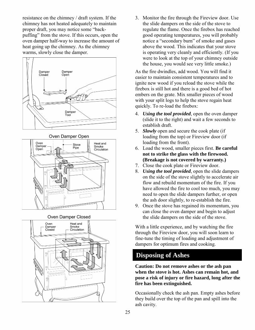
resistance on the chimney / draft system. If the chimney has not heated adequately to maintain proper draft, you may notice some “back-puffing” from the stove. If this occurs, open the oven damper half-way to increase the amount of heat going up the chimney. As the chimney warms, slowly close the damper.
3. Monitor the fire through the Fireview door. Use the slide dampers on the side of the stove to regulate the flame. Once the firebox has reached good operating temperatures, you will probably notice a “secondary burn” of smoke and gases above the wood. This indicates that your stove is operating very cleanly and efficiently. (If you were to look at the top of your chimney outside the house, you would see very little smoke.)
As the fire dwindles, add wood. You will find it easier to maintain consistent temperatures and to ignite new wood if you reload the stove while the firebox is still hot and there is a good bed of hot embers on the grate. Mix smaller pieces of wood with your split logs to help the stove regain heat quickly. To re-load the firebox:
4. Using the tool provided, open the oven damper (slide it to the right) and wait a few seconds to establish draft.
5. Slowly open and secure the cook plate (if loading from the top) or Fireview door (if loading from the front).
6. Load the wood, smaller pieces first. Be careful
not to strike the glass with the firewood.
(Breakage is not covered by warranty.) 7. Close the cook plate or Fireview door. 8. Using the tool provided, open the slide dampers
on the side of the stove slightly to accelerate air flow and rebuild momentum of the fire. If you have allowed the fire to cool too much, you may need to open the slide dampers further, or open the ash door slightly, to re-establish the fire.
9. Once the stove has regained its momentum, you can close the oven damper and begin to adjust the slide dampers on the side of the stove.
With a little experience, and by watching the fire through the Fireview door, you will soon learn to fine-tune the timing of loading and adjustment of dampers for optimum fires and cooking.
Caution: Do not remove ashes or the ash pan
when the stove is hot. Ashes can remain hot, and
pose a risk of injury or fire hazard, long after the
fire has been extinguished. Occasionally check the ash pan. Empty ashes before they build over the top of the pan and spill into the ash cavity.
Disposing of Ashes

26
1. When the fire is out and the stove has cooled for several hours, open the Fireview door and left cook plate. Use the rake provided to push loose ash and small embers through the holes in the grate and into the ash pan.
2. Slide the top side damper all the way to the back. This will align the slots in the damper and the bottom of the left brick. Use the narrow end of the rake to push accumulated ash through the slots and into the damper tube. Place a fireproof container under each end of the damper tube. Slide the damper back and forth to shake the ash into the containers.
3. Close the fire door and cook plate. Wearing heat-resistant gloves, open the ash door. Using the handle of the ash pan, slide the pan towards the front of the stove.
4. When the pan is almost out of the stove, tip the handle up into the carrying position. Place one hand on the handle and one on the ash pan to prevent tipping. Carry the pan in this position.
5. After disposal, replace the ash pan in the stove, handle facing forward, and close the door.
NEVER ATTEMPT TO REMOVE ASHES
WHEN THE STOVE IS HOT. DOING SO
COULD RESULT IN SEVERE BURNS AND /
OR FIRE.
Disposal of Ashes - Ashes should be placed in a metal container with a tight fitting lid. The closed container of ashes should be placed on a noncombustible floor or on the ground, well away from all combustible materials, pending final disposal. If the ashes are disposed of by burial in soil or otherwise locally dispersed, they should be retained in the closed container until all cinders have thoroughly cooled. Do not carry hot ashes
through the house or other buildings. Do not
place the ash pan or disposal container on a
combustible floor, or against or near any
combustible materials, gases or liquids.
Temperatures of the cooking surface, oven and warmer(s) are determined by: 1. Draft: Adjusting the slide dampers on the side
of the stove will allow you to increase or decrease the burn rate of your fire. The further open the dampers, the hotter the fire will be.
2. Oven Damper: Closing the oven damper (sliding it to the left) not only heats the oven; it also channels heat across the entire cooktop. When the oven damper is open, most of the heat will travel to the flue and directly up the chimney - there will be a great deal of heat on the cooktop directly over the firebox, but relatively little on the right side of the cooktop.
3. Fuel: The amount of fuel in the firebox and its state of combustion (start-up, fast burn, coals).
Griddling directly on the cook plates is not
recommended. Doing so will create a hard-to-
clean mess, and rusting and staining of the top. [During the first few firings, the cooktop will begin to change color. This is normal “seasoning” of the stove. Over time, the color will become fairly consistent across the top. To reduce staining and
prevent rusting, use a cloth to apply a fine coating of vegetable oil to the entire cooktop. Apply oil only when the stove is cool. You may notice a small amount of smoke as the oil burns off the next time you fire your stove.] Cooking on a wood-burning stove is much more flexible than on a modern range. Various areas of the top have very different temperatures (hottest on the left / rear and coolest on the right / front, as you move away from the firebox and flue channel). Rather than moving a pot from burner to burner, or turning down the heat, simply move the cooking vessel to the area with the heat you desire.Unlike a gas or electric range, the entire surface of the cooktop can be used for cooking - it provides a very large cooking surface for pots, pans, griddles, etc. Caution: Your cooktop will remain hot long after the flame is reduced or extinguished. With a little practice, experimentation and experience, you will soon become very familiar
Cooking: Surface, Oven, Warmers & Gas Burners
Stove Top Cooking
Cooktop Guidelines, Instructions
& Tips:

27
with how your dampers control the cooktop temperatures, and which sections are best for various types of cooking.
You can begin cooking as soon as the cooktop over the firebox heats up; however you will find it much easier to maintain consistent temperatures and avoid burning foods if you wait until a consistent fire and temperature has been established in the firebox.
Once the fire is established, use the slide dampers on the side of the stove to regulate the fire.
Close the oven damper at the back of the cooktop to channel the heat under the cooktop and create a higher, more consistent heat, or open it to channel heat directly up the flue and away form the cooking surface. It will take some time for the cooktop to react to changes in the oven damper – do not expect an immediate change in cooktop temperatures.
Boiling, griddling and fast frying will be best accomplished on the left side of the cooktop; simmering and slow cooking are better accomplished on the cooler right side. If even lower temperatures are required on the right side, open the oven damper accordingly to reduce the cooktop temperature.
Use flat-bottomed cooking vessels.
Always use the tool provided to adjust dampers,
and open or close doors. Do not touch hot controls
with bare hands. Note: The thermometer on the stove door has been factory-calibrated to indicate approximate oven temperatures. As it is basing its readings on temperatures in the door, it will vary from actual oven temperatures. You can calibrate the thermometer, following the directions below, for more accurate readings. However, as with all wood-burning cookstoves, readings will be approximate. Use the interior oven thermometer provided for
accurate oven temperature readings. The temperature in the oven of a wood-burning cookstove will vary from top-to-bottom, side-to-side and front-to-back, depending on the duration of cooking and the nature of the fire. You may find it
beneficial with some foods to rotate the pan from time to time during cooking, in order to achieve a more consistent cooking level. As with stovetop cooking, learning how to regulate temperatures in your oven is part science and part art. You should be able to obtain satisfactory results quickly, but experience will allow you to get even better as you become more familiar with the operation of your Fireview stove. The oven will heat up quickly once you close the oven damper, but it is best to wait until your fire is well established and you have a good charcoal fire before attempting to use the oven. Typically, it will take an hour or two from start-up, and three or four charges of full-sized wood, before your firebox has established a bed of coals suitable for oven cooking. 1. Use the Fireview door to monitor the fire. 2. Before using the oven, establish a steady fire in
the firebox, and ensure a good bed (4 – 5” of red-hot coals has been established in the firebox. (See “Starting a Fire” and “Maintaining a Fire” on page .) At this point, you will have very consistent temperatures in the firebox and circulating around the oven box.
3. Open the oven damper by sliding it to the right. Lift the cook plate or open the Fireview door slowly to add a new charge of wood.
4. Add a full charge of wood (including a few smaller pieces for faster ignition) to the firebox and allow the fire to re-establish its momentum. Use the slide dampers on the side of the stove to maintain a slow, steady burn.
5. Once the new wood has caught, close the oven damper. Most of the heat will now be traveling around the oven, and the oven temperature will climb quickly. Adjust the oven damper, open or closed, to regulate the oven temperature. Remember, it will take several minutes for adjustments in the oven damper to be reflected in the oven’s internal temperatures.
6. Continue to monitor the fire through the Fireview door, and recharge the wood when the fire is reduced to 4 – 5” of red-hot coals. Avoid letting the fire dwindle beyond this point. If you do so, the oven temperature will cool and you will have to open the dampers (further cooling the firebox and oven) to re-ignite the new charge of wood.
Oven Cooking
28
Before loading wood, always open the oven damper and wait a few seconds before opening the cook plate or Fireview door.
For best performance, clean creosote and soot regularly from the channels around the oven. This will ensure smooth flow of air and even heating of the oven box.
Door Thermometer Calibration
Your door thermometer has been calibrated at the factory to provide fairly accurate readings in the 300 to 400 degree Fahrenheit range. To calibrate your thermometer: 1. Following the directions above, establish a
steady red-coal fire in your stove. 2. Use the damper controls to establish an oven
temperature of approximately 350°F, according
to the internal oven thermometer. 3. Note the difference between the door
thermometer and the internal thermometer. (if the door thermometer reads 300°F, and the internal thermometer reads 350°F, you will want to calibrate the door thermometer UP 50°F.)
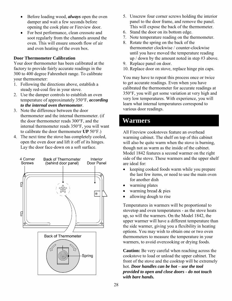
4. The next time the stove has completely cooled, open the oven door and lift it off of its hinges. Lay the door face-down on a soft surface.
5. Unscrew four corner screws holding the interior panel to the door frame, and remove the panel. This will expose the back of the thermometer.
6. Stand the door on its bottom edge. 7. Note temperature reading on the thermometer. 8. Rotate the spring on the back of the
thermometer clockwise / counter-clockwise until you have moved the temperature reading up / down by the amount noted in step #3 above.
9. Replace panel on door. 10. Replace door on stove, replace hinge pin caps. You may have to repeat this process once or twice to get accurate readings. Even when you have calibrated the thermometer for accurate readings at 350°F, you will get some variation at very high and very low temperatures. With experience, you will learn what internal temperatures correspond to various door readings.
All Fireview cookstoves feature an overhead warming cabinet. The shelf on top of this cabinet will also be quite warm when the stove is burning, though not as warm as the inside of the cabinet. Model 1842 features a second warmer on the right side of the stove. These warmers and the upper shelf are ideal for: keeping cooked foods warm while you prepare
the last few items, or need to use the main oven for another dish
warming plates warming bread & pies allowing dough to rise
Temperatures in warmers will be proportional to stovetop and oven temperatures - as the stove heats up, so will the warmers. On the Model 1842, the upper warmer will have a different temperature than the side warmer, giving you a flexibility in heating options. You may wish to obtain one or two oven thermometers to measure the temperature in your warmers, to avoid overcooking or drying foods. Caution: Be very careful when reaching across the cookstove to load or unload the upper cabinet. The front of the stove and the cooktop will be extremely hot. Door handles can be hot – use the tool
provided to open and close doors - do not touch
with bare hands.
Warmers

29
Model 1842-G dual fuel stove is equipped with two sealed gas burners and a battery-powered ignition system. These burners are convenient for quick cooking tasks when you don’t want to wait for the cooktop to heat up, or warm days when you don’t want the heat of a fire. The sealed gas burners spread the heat evenly across the bottom of the cooking utensil and provide infinite heat control. There are no standing pilots to light or adjust. See “Gas Burner Cleaning” below for maintenance of burners.
Igniting Gas Burners The control for the back burner is on the right; front burner on the left. The igniter will send a spark to both burners when pushed. To ignite:
1. Push and turn the burner control knob counter-clockwise to the “LIGHT” position. The igniter will begin to spark on both burners.
(If the igniter does not spark, ensure burner caps are aligned correctly, with the dimple on the cap in the recess in the burner. If the igniter still does not spark, replace the battery in the igniter. If the problem persists, contact Elmira for assistance.) 2. Once the flame is ignited, turn the control knob
to the desired temperature. 3. When you are finished cooking, turn the knob to
the “OFF” position. Caution: Never leave a burner unattended. Your gas burners feature “push and turn” functionality to prevent accidental gas flow. Do not allow children to play with or near the stove.
If you experience an emergency situation, refer to
the Safety Instructions, such as “Over-Firing -
Caution!” and “If You Smell Gas” (page 3). These tips are intended to assist with simple, non-emergency problems you might encounter with your stove. If you require additional assistance call
Elmira Stove Works. When calling, please provide a complete description of the problem, your model and serial number, and the purchase or installation date. This information is needed to identify the problem and any parts or service needed.
For Service, call our help line at: 800-295-8498. Symptom Problem Cause Solution
Fire & Draft:
Difficulty lighting or maintaining fire, excessive smoking and/or back-puffing
Inadequate draft (see “Downdraft” in Glossary of Terms
Closing oven damper before chimney is heated
Chimney blockage Obstruction near chimney top
Chimney too short Cold chimney
Keep damper open until fire is established.
Inspect & clean chimney.
Remove obstruction or extend chimney.
Extend chimney (as a rule of thumb, the chimney should extend at least 16 feet above the floor on which the stove is located).
Insulate or enclose chimney (follow codes).
Trouble-Shooting
Gas Burner Operation
(Model 1842-G)

30
Oversized chimney liner – stove is designed for a 6” flue and liner
Negative pressure in house (caused by furnace, exhaust fans, dryer, etc.)
“Stack Effect” (prevalent in winter - warm air rising to upper stories pulls air from stove)
Blockage in tubular slide dampers
Install 6” liner (ideally, liner should have same internal area as the flue collar of the stove).
Turn off furnace and other exhaust factors when stove is burning.
Crack a window to allow air into room.
Increase chimney height to increase draft.
Crack a window to allow air into room.
Clean tubes with tooth brush or venturi brush.
Smoking or back-puffing when cook plate or Fireview door is opened
Temporarily inadequate draft to pull smoke up chimney
Oven damper is closed
Open damper prior to opening cook plate or door. Wait before opening plate or door.
Fire is difficult to control Excessive draft Too much draw on chimney
Install stove pipe damper above the upper cabinet (approx. 5-1/2’ above the floor.
Wood is hard to light - sizzles & steams
Wet / damp wood Inadequate “seasoning”
Moisture getting into stored wood
Allow wood to dry under cover for minimum of one year after splitting.
Keep split wood covered (sides open)
Oven Cooking: Oven won’t heat adequately Inadequate draft
Low firebox temperature Heat not reaching oven
Oversized chimney or liner
Wood is too large
Oven damper open
Install 6” flue / liner. Split to 3” x 3” for high, consistent heat.
Close damper. Inaccurate temperature readings
Door thermometer not accurate
Door thermometer does not provide highly accurate readings
Calibrate thermometer (page 28) for more accurate readings.
Use interior oven thermometer provided.
Foods in oven cooking unevenly
Inconsistent oven temperatures
Fire not stabilized prior to baking
Firebox cooling excessively during baking
Allow fire to stabilize (4-5” of red-hot coals).
Re-charge fire when wood burns down to 3/4” of red-hot coals.

31
Temperatures vary throughout oven
Rotate foods for more even results.
Top of foods in oven brown / burn excessively
Excessive heat in oven Uneven heat in oven
Fire too hot Food too close to top / back of oven
Wait until fire stabilizes to red-hot coals prior to baking.
Reduce fire using slide controls.
Open oven damper slightly to reduce heat.
Move foods to front. Move rack to bottom.
Cooktop Cooking: Foods burn / cook too quickly
Cooktop too hot Fire too hot Oven damper is closed, sending most heat across cooktop
Use slide dampers to regulate fire
Allow fire to stabilize before cooking.
Move cooking vessel to right side of cooktop.
Regulate cooktop temperature with oven damper.
Move cooking vessel to right side of cooktop.
Foods cook too slowly Cooktop not hot enough Fire not hot enough
Oven damper is open, sending most heat up chimney
Inadequate contact between cooking vessel and cooktop
Add fuel and / or use slide dampers to regulate fire.
Move cooking vessel to left side of cooktop.
Regulate cooktop temperature with oven damper.
Move cooking vessel to left side of cooktop.
Use flat-bottomed cooking vessels.
Gas Burners: Cooktop control knobs will not turn
Knobs have “push & turn” safety feature
Knobs not pushed prior to turning
Push knob, then turn to desired setting.
Burner(s) burn with uneven flame
Burner cap(s) are not level Cap(s) are not installed properly
Rotate cap until it is aligned properly and sits evenly in the burner base.
Burners spark, but one does not light
Burner must be clean to operate
Dirt on burner, cap, igniter or orifice
Clean dirt from entire burner assembly.
Igniter does not spark when knob is turned to “LIGHT”.
No electricity coming from igniter
Dead or low battery Defective igniter
Replace battery. Replace igniter.

32
Your cookstove will give you years of enjoyment and great cooking with little maintenance. However, some occasional maintenance is required and will keep your stove operating safely and efficiently.
When the oven damper of your stove is closed, smoke and heat travel through a channel around the oven, providing heat to the oven for baking and roasting. The smoke deposits “fly ash” and creosote on the outside walls of the oven and adjacent panels. As heat, smoke and gases travel around the oven, fly ash and often creosote are left behind. Fly ash – fine and light-colored - is produced through the clean, efficient burning of good, dry wood. Creosote – sticky and dark in color – is produced when wet wood is burned or when the stove is not being burned hot enough. Rapid build-up of creosote is a warning that you need to burn drier wood, burn your fires hotter (at least for one hour or so out of each burning cycle) and / or that you need to improve the draft of your chimney system to allow for hotter burns. A build-up of creosote in the flue chamber can lead to chimney fires and over-firing, along with foul odors and premature rusting of the stove and chimney system. The frequency with which the flue needs cleaning will depend on how often you burn the stove, quality of fuel and your burning habits and patterns. Clean flue passages only when the fire is out and the stove is cool. To clean the flue passage: 1. Remove the cook plates, exposing the flue
passage. 2. Using the smooth side of the ash tool provided,
scrape ash / creosote from the top of the oven box, across and down the right side of the oven.
3. Remove the nut and large blade from the tool. Use the small plate to scrape the ash down the right side of the oven box and adjacent panels. The ash will fall to the bottom of the channel.
4. Remove the cleanout plate by tapping it upwards and wiggling it out of the “keyholes”.
5. Place the ash pan under the cleanout opening and scrape ashes that have fallen down the side
and ashes accumulated under the oven through the cleanout opening and into the ash pan. Replace the cleanout plate.
6. Follow instructions for “Disposing of Ashes” on page 25 to dispose of the ashes.
The flue boot is located at the back of the range. Remove the stove pipe from the flue boot and scrape away any ash and / or creosote build-up in the flue boot. Remove the ash through the cleanout door and dispose of as instructed in “Disposing of Ashes” on page 25 of this manual.
A build-up of ashes and creosote may cause the oven damper to stick. Allow the stove to cool completely. Remove the left cookplates and scrape away ashes. If necessary, spray residue with a creosote remover. Allow to sit for 30 minutes and then remove remaining sludge. Do not re-fire the stove until all cleaner residue has been removed.
Creosote - Formation and Need for Removal - When wood is burned slowly, it produces tar and other organic vapors, which combine with expelled moisture to form creosote. The creosote vapors condense in the relatively cool chimney flue of a slow-burning fire. As a result, creosote residue
Maintenance & Adjustments
Oven Flue Passage - Cleaning
Flue Boot
Oven Damper
Chimney
33
accumulates on the flue lining. When ignited, this creosote makes an extremely hot fire. When burning wood, inspect the chimney connector and chimney at least once every two months during the heating season to determine if creosote buildup has occurred. If you notice dry, flaky deposits on the liner or a shiny, glazed coating, you have creosote build-up. Glazed creosote is extremely flammable and poses a serious fire hazard. Glazed creosote should be removed before it reaches 1/8” (3 mm.) in thickness. Dry creosote should be removed before it reaches ¼” (6 mm.) in thickness. Creosote will build up more quickly: When the chimney liner is cold. (Insulate the
chimney, install a liner to reduce flue size, burn the appliance hotter to heat the chimney.)
When wet or damp wood is burned. (Use only dry, well-seasoned wood.)
When fires are allowed to smolder. (Burn your fire hot for at least one hour out of each burn cycle.)
In the spring and fall, when less heat is wanted and fires are burned more slowly.
Chimney Cleaning
Unless you are adventurous and / or frugal, chimney cleaning is best left to a qualified chimney sweep. An experienced “sweep” will clean your chimney quickly, thoroughly and with no mess left behind; and you can be confident the job has been performed properly. The chimney sweep will also check the condition of the chimney and advise you of any repairs or corrections that are required. Your dealer may perform this service, or can probably refer you to a good chimney sweep in your area. If you choose to sweep your own chimney, you will require some simple equipment, available at most hardware stores and hearth shops. Chimneys are cleaned with brushes attached to the end of rods. The rods have threaded ends so they can be attached to one another, providing more length for taller chimneys. Only plastic brushes should be used in metal chimneys and steel brushes should be used in a masonry chimney. You will require enough surface contact and friction to remove the ash and creosote deposits, so the brush should fit snugly in the chimney. Make several passes of the brush up and down the chimney for a thorough cleaning.
During the first few hot firings of your Fireview cookstove, the cookplates will begin to change color. This is a normal process. As you burn the stove more, the color will become more consistent across the cooktop. To help prevent stains and rusting of the cookplates, apply a light coating of vegetable oil once the stove has completely cooled after each firing. When you are not going to be firing your stove for an extended period (longer than a week or so, and especially if you will be away from the stove for a full season), apply a heavy coating of oil. If possible, re-apply additional coats at least every four to six weeks. Clean up spills, and remove stains caused by wood, food, liquids and rust as soon as it is safe to do so. Stains allowed to set on the cookplates can become impossible to remove. Many stains, if caught soon enough, can be removed using a fine-to-medium aluminum oxide sanding block (available at most hardware stores) or a metal cleaner with fine steel wool. Over time, it is almost inevitable that your cooktop will sustain some stains and marks – think of them as signs of your stove’s authenticity. If you would like to restore the original swirled look of the top, you can do so by sanding the top with an orbital sander and 100-grit sanding disk. Oil the top after sanding to prevent rusting.
Burner caps should be routinely removed and cleaned. Always clean caps after a spillover. Keeping the caps clean aids in proper ignition and an even flame. For proper flow of gas and ignition of the burner, DO NOT ALLOW SPILLS, FOOD, CLEANING AGENTS OR OTHER MATERIAL TO ENTER THE GAS ORIFICE OPENING. Gas must flow freely through the small hole in the brass orifice for the burner to light properly. This area must be free of any soil and be kept protected from spillovers. ALWAYS keep the burner caps in place whenever a surface burner is in use. Occasionally check flames for proper size and shape as shown. A good flame is blue in color. If
Cookplates
Gas Burner Cleaning

34
flames lift off ports they are yellow and usually noisy. You may need to clean the burners. To Clean Burners:
1. Lift the burner cap straight up from the base. 2. Clean burner cap with warm, soapy water and a
sponge. You can also clean with a nonabrasive scrubbing pad or cleanser.
3. If the gas orifice opening has become soiled or clogged, use a cotton swab or soft cloth to clean the area.
4. If ports are clogged, clean with a straight pin. Do not enlarge or distort port. Do not leave anything stuck in the ports.
5. After cleaning the orifice opening and ports, replace the burner cap. Make sure cap is set straight on burner and that the tabs on cap fit into grooves of burner base.
6. Check burner for proper lighting after cleaning.
Note: If gas burner burns with an uneven orange
flame, reposition the burner cap so it sits flat on the
housing. If burner lights slowly, have your gas
service person check the gas pressure to the stove.
When cleaning around the surface burner, use care. If cleaning cloth should catch the igniter, it could damage it, preventing ignition.
If surface burner does not light, check if igniter is broken, soiled or wet. If clogged, clean the small port beneath the igniter with a straight pin.
Wipe acid / sugar spills as soon as the cooktop
has cooled - these spills will discolor porcelain. Manual Burner Adjustment on Low The burners have been pre-adjusted at the factory for best performance. You may manually adjust the low settings up or down by removing the control knob while the burner is lit and in the low position. While holding the valve stem so it doesn’t turn, insert a small flat blade screwdriver into the stem and turn the small brass screw slightly in either direction until desired flame height is obtained. Valve must be adjusted so low flame licks around burner cap no less than 1/8”.
Manual Burner Adjustment on Low
Note: Low adjustment will not affect flame heights
at other settings.
Avoid operating the stove in a manner that will result in breakage or cracking of the Fireview glass – striking or slamming the door or glass, splashing liquids on hot glass, etc. Do not operate the stove with a broken or cracked Fireview glass. Cleaning:
Do not clean the glass when the fire is burning or the glass is hot.
Do not clean glass with abrasive cleansers. Scratching or etching the glass will weaken its integrity. Do not use steel wool or razor blades to clean the glass.
Clean glass as necessary using a low alkaline content commercial woodstove glass cleaner, available from most woodstove / hearth products dealers. Follow the manufacturer’s directions. Allow the stove and glass to cool thoroughly prior to cleaning.
For heavier deposits remove the door and lay it face down on a table or bench. Apply cleaner and allow to soak. Wipe clean with a soft cloth.
Replacement:
The Fireview glass is a ceramic shock-resistant glass, made specifically for use in wood-burning stoves. The glass should be replaced immediately if cracked or broken. Replace glass only with glass supplied by Elmira Stove Works for this stove. Do not use substitute materials. Your replacement glass will be accompanied by replacement instructions. If you replace the glass yourself, wear protective gloves and safety glasses. 1. Remove hinge caps and remove door from
hinges. Place face down on a table or work bench.
2. Remove two screws from each of three retaining clips. Set screws and clips aside.
3. Lift old glass out of door. Use caution when removing broken glass to avoid cuts.
4. Place new (gasketed) glass in cavity in door, with the non-gasketed side facing the top of the door. (Glass is shipped with gasket installed.)
5. Replace clips and screws. Do not over-tighten. 6. Replace door on hinges and replace hinge caps.
Fireview Glass Cleaning &
Replacement
35
Replacing the 9 volt battery in your stove’s igniter is a simple and easy process: 1. Grasp the igniter knob and turn counter-
clockwise to unscrew it from the assembly. 2. Remove the battery and replace with a new 9-
volt battery. Polarity (+/-) does not matter. 3. Screw the knob clockwise onto the assembly. If the igniter fails to spark after replacing the battery, remove and test the battery. If the battery is fully charged, the igniter may need replacement.
Wipe acid or sugar spills as soon as the cooktop
has cooled as these spills will discolor the
porcelain. Exterior porcelain and powder coated surfaces can be cleaned with warm soapy water and a soft cloth. Allow hardened spills to soak. For a high sheen, spray with window cleaner and polish after cleaning and rinsing. Do not clean porcelain
finishes when hot. Sudden changes in temperature
may crack the porcelain.
Do not use abrasive cleansers, scrubbers or cloths on nickel trim. Abrasives will scratch or cloud the finish. Clean nickel trim with a soft, non-abrasive cloth and warm soapy water. Rinse and polish dry. To remove tarnish from nickel trim, use a fine polish such as Maas, available through many hardware stores or through Elmira Stove Works.
The oven can be cleaned with normal household oven cleaner. Follow the manufacturer’s directions.
Inspect the gaskets around the Fireview door, ash door and oven door regularly to ensure they are sealing properly. A poor seal on the fire door or ash door will result in reduced control of burn rates and inefficient fires. A poor seal on the oven door will result in inconsistent oven temperatures.
Replacement gasket and adhesive can be ordered from Elmira Stove Works or your dealer. Loose gasket that is still in good condition can be re-applied using high-temperature silicone. Gasket is sold by the foot, or as an assembly. Installation instructions are supplied with the gasket. Refer to the gasket listing below. oven door - gasket assembly fire door - 3 feet of 3/8” rope gasket ash door - 3 feet of 3/8” rope gasket Fireview glass – 2 feet of flat window gasket
Periodically clean and inspect the firebox of your stove. Ensure ash and debris are not blocking the air intakes from the slide dampers on the left side of the stove. Your fire bricks are reinforced with stainless steel strands to resist cracking; however minor cracks are normal – larger cracks can be repaired with stove cement. Badly cracked or broken firebricks should be replaced immediately. To protect your firebox and its components: Avoid impacting the Fireview door glass with
wood or other objects that may break the glass. Do not allow firewood to burn directly against the glass.
Do not allow water or other cool liquids to come into contact with the glass when it is hot.
Clean the Fireview glass as necessary with woodstove glass cleaner, Follow the manufacturer’s directions. Allow the glass to cool fully before cleaning.
Avoid impacting fire brick with firewood. Burn dry seasoned wood. Do not let ashes spill over the top of the ash pan
– empty the ash pan regularly.
Firebrick and grate are shipped in place. You can remove them to reduce weight, or for replacement. Removal:
1. Remove the left cookplate: Lift the left side of the plate. Slide the plate slightly to the left (out from under the next cookplate). While guiding
Nickel Trim
Oven Compartment
Door Gaskets
Igniter Battery
Porcelain / Powder Coated Finishes
Firebox
Removing & Replacing
Firebrick & Grate

36
the lifter handle (if the lifter is attached) through the cabinet bracket, lift the plate off of the stove.
2. Remove the retaining clip holding the top of the rear fire brick. While standing behind the stove, hold the clip and undo the screw on the back of the range which holds the clip in place. (If you have a heat shield, the side section may have to be removed to access the screw.)
3. Carefully remove the brick. 4. Open the Fireview door. Grasp the nut under the
inside center of the door with pliers and undo the corresponding bolt on the front of the stove (middle of the ash catch).
5. Lift the small stainless steel sheathed fire brick out from under the Fireview door.
6. Remove the secondary air tube above the right fire brick by removing the screw holding it in place and wiggling the tube free. Grasp the brick and lift it out of the firebox.
7. Grasp the large fire brick on the left side of the firebox by the grooves in the bottom of the brick. Gently lift the brick and slide the bottom out over the retaining pin on the wood grate, so the top of the brick can clear the retainer above.
8. Put fingers through holes in grate (do not get fingers stuck) and gently lift out of firebox.
Replacement:
1. Grasp the grate by placing fingers through holes. (Do not get fingers stuck.) In the proper position, the grate slopes down to the middle and the retaining pins on the top of the grate
are at the back. Angle the grate into the firebox and rest it on the grate stand.
2. Angle the largest firebrick into the firebox. Grooves are on the bottom of the brick. Rest the brick on the grate with the bottom a few inches away from the left side of the firebox. Slide the bottom to the left, up and over the retaining pin on the grate, to slip the top of the brick under the steel retaining bracket. Slide the brick as far forward in the firebox as possible. (Positioning is important, since air must flow through the grooves in the bottom of the brick.)
3. Place the other large fire brick in the firebox and slide it up against the right wall of the firebox. Replace the secondary air tube above the brick and secure in place by tightening the screw.
4. Open the Fireview door. Place the small stainless steel-sheathed fire brick immediately under the door, with the fully sheathed side facing the back of the stove. Insert the bolt through the hole under the door and through the brick. (You may need a screw driver to thread the bolt through the brick.) Attach the nut and tighten the bolt. Do not over-tighten.
5. Place the final firebrick in place in the back of the firebox. It will be held in place on the bottom by small pins on the back of the grate. Attach the retainer clip above the top of the brick by inserting the screw through the back of the stove into the clip. Tighten screw. (For the first installation of the firebrick the clip and screw can be found in the hardware package in the ash pan.)

37
Ash Rake / Ash / Clean-out Tool: tool used to scrape ash from around the oven and flue boot. Ash is scraped from the sides and top of the oven and flue boot, and out clean-out door below the oven. Back-draft (also Down-draft): reversal of air flow in the chimney and stove (air comes down the chimney - caused by negative pressure in building and / or exterior wind conditions – results in emission of smoke through the stove into the room. Back-puffing: puffs of smoke out of dampers and openings in the stove when oxygen is suddenly introduced to an oxygen-starved fire. Occurs most often when a door, cookplate or damper is opened too quickly and the chimney cannot absorb the sudden supply of air. Open doors, plates and dampers slowly to avoid back-puffing. Open oven damper prior to opening doors, plates or dampers. Bank / Banking the Fire - loading the firebox with enough fuel for a long burn cycle - a bed of coals 3 – 5” deep is required for proper banking. Charging the fire – adding a load of wood – done when the fire from the previous load is well established (when the wood in a start-up fire has gained momentum or when a 3-5” bed of hot coals exists in an established fire). Chimney Connector – horizontal pipe running between the flue pipe and chimney. Clearances – distances that must be maintained between stove, flue pipe and chimney parts and nearby combustibles – the greater the distance, the more air will cool before contacting combustibles. Cookplate - section of the stovetop, lifted to load fuel or make repairs to the firebox – also the surface on which stovetop cooking is done. Creosote – condensate created by tar, organic vapors and moisture - condense when hot smoke and ash contact cooler surfaces of the oven channel, flue / chimney assembly and firebox – extremely flammable and can cause dangerous chimney fires – remove regularly to prevent fire hazard. Dampers – devices used to control inflow of combustion air or outflow of smoke / exhaust gases. Down-draft (also back-draft) – when outside air is warmer than the air inside the house, smoke will have difficulty drafting up the chimney. This condition is most prevalent on warm fall days and / or days with very low pressure. Another cause of
down-drafting is excessive build-up of creosote in the chimney, which restricts the flow of flue gases. Fire Glove – a heat and fire-resistant glove available at most stove / hearth products stores. Fireview Door – glass door on the left front of the stove – used to enjoy the view of the fire, monitor the fire and load wood. Flue Boot – metal assembly mounted to the back of the stove that channels smoke and gases from the stove up the stove pipe and chimney. Flue Pipe (also called smoke pipe, stove pipe) – the interior pipe running between the stove and the chimney or chimney connector. Heat Shield – a non-combustible assembly used to reduce clearances required between the stove and nearby combustible walls and other materials – mounts to the back of the stove and pipe. Lift Handle - handle on the left back side of the cooktop, used to lift the cookplate – provides access to the firebox for loading fuel and maintenance. Oven Cleanout - door below oven - removed to scrape and remove ashes from below oven. Oven Damper – located on the back left side of the cooktop – routes heat directly up the chimney, or around the oven to heat the oven and cooktop. Open the damper before opening doors, cookplates or dampers to prevent back-puffing. Oven Flue Passage – channel around oven (between oven & cooktop, side of stove and bottom of stove. When the oven damper is closed, hot air travels through this channel, heating the oven. Pipe Damper – optional damper located in the flue pipe above the stove – used to control draft in installations with excessive draft (usually more than a 20’ chimney height). Rake - tool used to scrape ash and creosote from the flue passage around the oven. Smoke Pipe, Stove Pipe – see Flue Pipe Warmer (see also Warming Cabinet / Warming
Closet) – either of the warm air cabinets located above the cooking surface or to the right of the main oven. Temperatures in these cabinets vary depending on temperature of the oven and cooktop. Warming Cabinet / Warming Closet – upper cabinet above the cooktop – provides storage and warming for plates and food.
Glossary of Terms

38
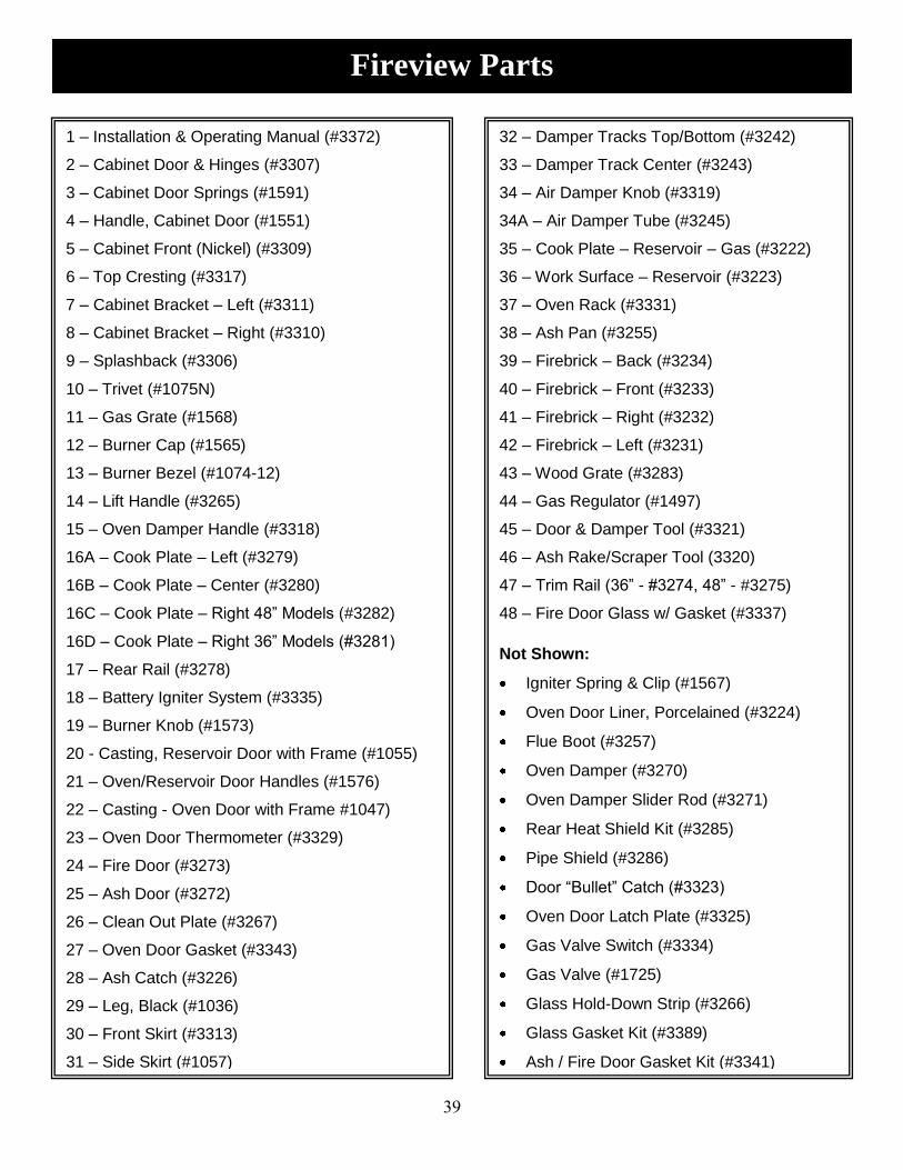
39
Fireview Parts
1 – Installation & Operating Manual (#3372)
2 – Cabinet Door & Hinges (#3307)
3 – Cabinet Door Springs (#1591)
4 – Handle, Cabinet Door (#1551)
5 – Cabinet Front (Nickel) (#3309)
6 – Top Cresting (#3317)
7 – Cabinet Bracket – Left (#3311)
8 – Cabinet Bracket – Right (#3310)
9 – Splashback (#3306)
10 – Trivet (#1075N)
11 – Gas Grate (#1568)
12 – Burner Cap (#1565)
13 – Burner Bezel (#1074-12)
14 – Lift Handle (#3265)
15 – Oven Damper Handle (#3318)
16A – Cook Plate – Left (#3279)
16B – Cook Plate – Center (#3280)
16C – Cook Plate – Right 48” Models (#3282)
16D – Cook Plate – Right 36” Models (#3281)
17 – Rear Rail (#3278)
18 – Battery Igniter System (#3335)
19 – Burner Knob (#1573)
20 - Casting, Reservoir Door with Frame (#1055)
21 – Oven/Reservoir Door Handles (#1576)
22 – Casting - Oven Door with Frame #1047)
23 – Oven Door Thermometer (#3329)
24 – Fire Door (#3273)
25 – Ash Door (#3272)
26 – Clean Out Plate (#3267)
27 – Oven Door Gasket (#3343)
28 – Ash Catch (#3226)
29 – Leg, Black (#1036)
30 – Front Skirt (#3313)
31 – Side Skirt (#1057)
32 – Damper Tracks Top/Bottom (#3242)
33 – Damper Track Center (#3243)
34 – Air Damper Knob (#3319)
34A – Air Damper Tube (#3245)
35 – Cook Plate – Reservoir – Gas (#3222)
36 – Work Surface – Reservoir (#3223)
37 – Oven Rack (#3331)
38 – Ash Pan (#3255)
39 – Firebrick – Back (#3234)
40 – Firebrick – Front (#3233)
41 – Firebrick – Right (#3232)
42 – Firebrick – Left (#3231)
43 – Wood Grate (#3283)
44 – Gas Regulator (#1497)
45 – Door & Damper Tool (#3321)
46 – Ash Rake/Scraper Tool (3320)
47 – Trim Rail (36” - #3274, 48” - #3275)
48 – Fire Door Glass w/ Gasket (#3337)
Not Shown:
Igniter Spring & Clip (#1567)
Oven Door Liner, Porcelained (#3224)
Flue Boot (#3257)
Oven Damper (#3270)
Oven Damper Slider Rod (#3271)
Rear Heat Shield Kit (#3285)
Pipe Shield (#3286)
Door “Bullet” Catch (#3323)
Oven Door Latch Plate (#3325)
Gas Valve Switch (#3334)
Gas Valve (#1725)
Glass Hold-Down Strip (#3266)
Glass Gasket Kit (#3389)
Ash / Fire Door Gasket Kit (#3341)

40
Reduces required clearances to allow installation closer to rear walls.
Accessories are available through your dealer, or call Elmira Stove Works, 519-669-1281, Toll-free 800-295-8498, Fax 519-669-1774.
Options & Accessories
Heat Shield Kit (#3285 body,
#3286 pipe)

41
Warranty
Elmira Stove Works’ HelpLine Number
1-800-295-8498
Your Fireview stove is warranted by Elmira Stove Works to be free from defects
in material and workmanship for a period of two years from the date of purchase.
Elmira Stove Works will replace any parts which become defective during the period of this warranty.
Glass, enamel, porcelain coatings and nickel plating are not covered by warranty. The warranty does not include normal wear of fire brick, firebox parts or gaskets.
This warranty is subject to the terms and conditions outlined below.
Terms and Conditions
This warranty applies only for domestic use when the stove has been properly
installed according to instructions supplied by Elmira Stove Works in this manual, and to local building and safety codes. The stove must be connected to an adequate and proper chimney with
proper chimney connections. Damage due to faulty installation, improper use and care, abuse, accident, fire, flood or acts of God cancels all obligations under this warranty.
Neither Elmira Stove Works nor the dealer is liable for any damages or claims resulting from failure of the stove. Parts replaced through this warranty
are warranted for the balance of the original warranty period.
Purchase Date: _____________________ Store: _ ______________________
Store Address: ___________________________________________________
Stove Model ___________________________________
Serial Number __________________________________
CAUTION: Repeated and / or extended over-firing
of this stove is dangerous and will void the warranty.
Elmira Stove Works 285 Union Street, Elmira, ON Canada N3B 3P1
Tel: 519 669-1281 Fax: 519 669-1774 Toll-Free: 800-295-8498 E-mail: [email protected]