19 examination subject name: advanced manufacturing
TRANSCRIPT

MAHARASHTRA STATE BOARD OF TECHNICAL EDUCATION (Autonomous)
(ISO/IEC - 27001 - 2013 Certified)
__________________________________________________________________________________________________
Page No: 01/ 20
SUMMER – 19 EXAMINATION Subject Name: Advanced Manufacturing Process Model Answer Subject Code:
Important Instructions to examiners: 1) The answers should be examined by key words and not as word-to-word as given in the model answer
scheme. 2) The model answer and the answer written by candidate may vary but the examiner may try to assess the
understanding level of the candidate. 3) The language errors such as grammatical, spelling errors should not be given more Importance (Not
applicable for subject English and Communication Skills. 4) While assessing figures, examiner may give credit for principal components indicated in the figure. The
figures drawn by candidate and model answer may vary. The examiner may give credit for any equivalent figure drawn.
5) Credits may be given step wise for numerical problems. In some cases, the assumed constant values may vary and there may be some difference in the candidate’s answers and model answer.
6) In case of some questions credit may be given by judgement on part of examiner of relevant answer based on candidate’s understanding.
7) For programming language papers, credit may be given to any other program based on equivalent concept.
Q.
No.
Sub
Q.
N.
Answer Marking
Scheme
1a Attempt any THREE of the Following 12
(i) Draw neat sketch of wire cut EDM. Explain the working Principle. 04
Ans Working Principle: The basic mechanism of metal removal in WEDM is identical to that in die sinking type
EDM. Instead of moving electrode, the electrode in this process is a moving wire of CU or
brass. A vertically oriented wire is fed into the work piece continuously travelling from a
supply spool to take a spool, so that it is continuously renewed , since it will get worn out
during the process
Figure: Wire Cut EDM
02
Marks
For
Working
Principle
&
02
Marks
For
Neat
Labelled
Sketch
(ii) State and explain any four process parameters of Laser Beam Machining. 04
17527

MAHARASHTRA STATE BOARD OF TECHNICAL EDUCATION (Autonomous)
(ISO/IEC - 27001 - 2013 Certified)
__________________________________________________________________________________________________
Page No: 01/ 20
Ans
Process parameters of Laser Beam Machining:
a) Intensity of laser beam: By focusing a laser beam in a spot of 0.01 m 2 , it can give power
density of 100000kW/ cm2. The focused beam radius is directly proportional to the laser
wavelength and the focal length.
b) Pulse duration of laser beam: The pulse durations about 6 to 12 pulse/ min. It depends
upon the application to be performed like welding, drilling, cutting etc.
c) Focal length: It is the distance between laser beam and the workpiece. If the laser is very
close to the workpiece the divergence of the beam occurs for small focal length in the metal
cutting. : It is important in drilling operation.
d) Mode of laser operation : It can operate in continuous mode and pulsed wave mode
02
Marks
For
List
of
four
Parameters
&
02
Marks
For
Their
Explanation
(iii) Differentiate between open loop and closed loop control system 04
Ans Parameter Open loop Closed loop
Design Simple Complex
Feedback No feedback element Feedback system is present
Input The input is directly given to the
MCU
The input and feedback signal is
given to the comparator which
sends the required signal to the
MCU
Output The output may not be as desired The output given is exactly as
desired
Time Time required for processing is
less
Time required for processing is
More
Cost Cheaper Expensive
01
Mark
Each
Any
4
Points
(iv) State the advantages and limitations of Broaching Machine. 04
Ans
Advantages (Any Four)
1) Broaching is faster than other machining operations
2) It enables higher rate of production with more accuracy & finish than other machining
operations
3) It has longer tool life than other cutting tools. Tool cost per job is low
4) Both roughing & finishing operations are done by single tool
5) Interchangeable components can be produced at much faster rate in Broaching
6) Broaching operation does not require highly skilled operator
Limitations: (Any Four)
1) High tool cost
2) Very large work pieces cannot be machined
3) The surfaces to be broach cannot have an obstruction
4) Large amount of stock ( Material removal) cannot be removed
5) Work pieces must be rigidly supported
01/2
Mark
for
Each
Advantage
and
01/2
Mark
for
Each
Limitation
1b Attempt any ONE of the following 06
(i) Draw the set up for Abrasive Jet Machining. Explain the working principle and its
process parameters. 06

MAHARASHTRA STATE BOARD OF TECHNICAL EDUCATION (Autonomous)
(ISO/IEC - 27001 - 2013 Certified)
__________________________________________________________________________________________________
Page No: 01/ 20
Ans Abrasive Jet Machining:
Figure: Set up of Abrasive Jet Machining
Working Principle: In Abrasive Jet Machining (AJM), usually air is directly taken from atmosphere, cleaned
it and compressed it to a high pressure with the help of compressor. Loose abrasive
particles having predefined average size are mixed with this pressurized gas in certain
proportion (mixing ratio) and the mixture is then allowed to strike the work surface in
the form of jet at a particular incident angle at very high velocity. A nozzle converts the
hydraulic energy (pressure) of the jet-abrasive mixture into kinetic energy (velocity).
After cutting action, grits leave the machining zone, which are then collected and
disposed safely (usually, abrasive grits cannot be reused as grits lose sharpness after first
impact).
Process Parameters:
(1) Abrasive Mass Flow Rate:
Mass flow rate of the abrasive particles is a major process parameter that influences the
metal removal rate in abrasive jet machining. In AJM, mass flow rate of the gas (or air)
in abrasive jet is inversely proportional to the mass flow rate of the abrasive particles.
Due to this fact, when continuously increasing the abrasive mass flow rate, Metal
Removal Rate (MRR) first increases to an optimum value (because of increase in
number of abrasive particles hitting the workpiece) and then decreases. However, if
the mixing ratio is kept constant, Metal Removal Rate (MRR) uniformly increases with
increase in abrasive mass flow rate.
(2) Nozzle Tip Distance:
Nozzle Tip Distance (NTD) is the gap provided between the nozzle tip and the
workpiece. Upto a certain limit, Metal Removal Rate (MRR) increases with increase in
nozzle tip distance. After that limit, MRR remains constant to some extent and then
decreases. In addition to metal removal rate, nozzle tip distance influences the shape and
diameter of cut. For optimal performance, a nozzle tip distance of 0.25 to 0.75 mm is
provided.
(3) Gas Pressure:
Air or gas pressure has a direct impact on metal removal rate. In abrasive jet machining,
metal removal rate is directly proportional to air or gas pressure.
(4) Velocity of Abrasive Particles:
Whenever the velocity of abrasive particles is increased, the speed at which the abrasive
particles hit the workpiece is increased. Because of this reason, in abrasive jet
02
Marks
for
Sketch
02
Marks
for
Working
Principle
&
01
Marks
for
List
of
Process
Parameters
&
01
Mark
for
Explanation
of
Any
One
Parameter

MAHARASHTRA STATE BOARD OF TECHNICAL EDUCATION (Autonomous)
(ISO/IEC - 27001 - 2013 Certified)
__________________________________________________________________________________________________
Page No: 01/ 20
machining, metal removal rate increases with increase in velocity of abrasive particles.
(5) Mixing Ratio:
Mixing ratio is a ratio that determines the quality of the air-abrasive mixture in Abrasive
Jet Machining (AJM).It is the ratio between the mass flow rate of abrasive particles and
the mass flow rate of air (or gas). When mixing ratio is increased continuously, metal
removal rate first increases to some extent and then decreases.
(6) Abrasive Grain Size:
Size of the abrasive particle determines the speed at which metal is removed. If smooth
and fine surface finish is to be obtained, abrasive particle with small grain size is used. If
metal has to be removed rapidly, abrasive particle with large grain size is used.
(ii) Explain with sketch axis identification for CNC lathe and VMC 06
Ans CNC Lathe:
Figure: Axis Identification for CNC Lathe
In lathe only two axes are there;
Z axis--- The axis of rotation of the workpiece is specified by Z axis
X axis--- The radial location of the cutting tool is represented by X axis
VMC:
Figure: Axis Identification for CNC Lathe
(1) Z axis---1) Main spindle axis.
In VMC Z(+ve) means cutter movement upward.
In VMC Z(-ve) means cutter movement downward.
(2) X axis---1) Horizontal –work holding device.
X (+ve) means as being to the right when looking from the spindle towards column.
X (-ve) means as being to the left when looking from the spindle towards column.
(3) Y axis—It is perpendicular to X and Z axes. It indicates cross travel of the work table
02
Marks
for
Each
Neat
Labelled
Sketch
&
And
01
Mark
for
its
Explanation
2 Attempt any FOUR of the Following 16

MAHARASHTRA STATE BOARD OF TECHNICAL EDUCATION (Autonomous)
(ISO/IEC - 27001 - 2013 Certified)
__________________________________________________________________________________________________
Page No: 01/ 20
(a) State any four reasons for the need of non-traditional machining processes. 04
Ans Need of Non-Traditional Machining Processes: (Any four) 1) Replacement of existing manufacturing methods by more efficient & quicker methods.
2) Achievement of higher accuracies & quality of surface finish
3) Adaptability of cheaper materials in place of costlier one.
4) To do machining operations for “Hard to machine” materials like tungsten, uranium
5) To do machining operations on intricate & thin workpieces economically.
6) Development of new materials requires new methods
01
Mark
for
Each
Point
(b) Define Part Programming. Give a word address format for writing an instruction
along with the meaning of each term. 04
Ans Part Program:
Part programming – Part program defined as the way in which the blocks of instructions
are planned and written such that after its execution on the CNC machine the required
shape is obtained on the work piece in minimum possible time.
OR
Part program is a set of instructions the machine tool about the processing steps to be
performed the manufacture of component.
Word Address Format
For Example:-
N001 G01 X2.0 Y5.5 Z-3.0 F100;
N002 M06 T0101;
Meaning
N001 – Block No. 001
G01 – Preparatory Function(Linear Interpolation)
X2.0, Y5.5, Z-3.0 – XYZ Axis Movement.
F100 – Feed Rate in mm/min
M06 – Miscellaneous Function(Tool Change)
T0101 – Tool No. 01 with offset No 01
; - End of Block
01
Mark
for
Definition
&
03
Marks
for
Suitable
Example
and
its
Appropriate
Meaning
(c) Explain with neat sketch Up Milling and Down Milling 04
Ans Up milling:
it is the conventional milling process which is most commonly used. In this, the
material is removed by the cutter which is rotating against the direction of travel of the
work piece. As shown in fig., the thickness of the chip in the up milling is minimum at
the beginning of the cut and it reaches maximum when the cutter terminates. As the chip
thickness per tooth is not uniform, the cutting force in upmilling increases from zero to
maximum. The cutting force is directed upwards and it tends to lift the work from the
fixture. Due to this, difficulty is experienced in pouring coolant just on the cutting edge
from the chip begins. As the cutter progresses, the chip gets accumulated at the cutting
zone which spoils the machined surface. The surface milled by up milling is slightly
wavy as the cutter teeth do not begin their cut as soon as they touch the work surface.
01
Mark
for
Each
Figure
And
Explanation

MAHARASHTRA STATE BOARD OF TECHNICAL EDUCATION (Autonomous)
(ISO/IEC - 27001 - 2013 Certified)
__________________________________________________________________________________________________
Page No: 01/ 20
Figure: Up Milling
Down Milling:
It is also known as climb milling. In this, material is removed by the cutter which is
rotated in the same direction of travel of the work piece. As shown in fig., the thickness
of the chip is maximum when the tooth begins the cut and it reduces to minimum when
the cut terminates. The cutter tooth starts removing the metal immediately on reaching
the work piece, without sliding. The cutting force in down milling is maximum when the
tooth begins its cut and is minimum when the tooth leaves the work. Here the chips are
disposed off easily and do not interfere with the work. Fixture design is easier as the
cutting force tries to seat the work firmly in work holding devices. Coolant can be
poured directly at the cutting zone. This results in improved surface finish. If there is any
backlash in feed screw, it causes vibrations and damages work surface.
Figure: Down Milling.
(d) State and explain various indexing methods. 04
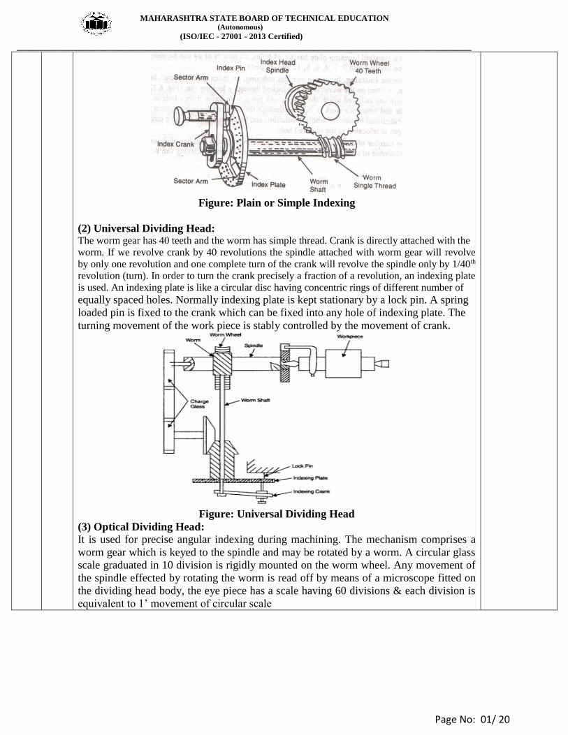
Ans (1) Plain or Simple Indexing.
In plain indexing the dividing head spindle is moved by turning the index crank. As the
shaft carrying the crank has a single threaded worm which mesh with the worm gear
having 40 teeth, 40 turns of the crank are necessary to rotate the index head spindle
though one revolution. To facilitate indexing to fractions of a turn, index plates are used
to cover practically all numbers. Index plates with circles of holes are as follows:-
Plate No. 1 – 15, 16, 17, 18, 19, 20
Plates No. 2 – 21, 23, 27, 29, 31, 33.
Plate No. 3 – 37, 39, 41, 43, 47, 49.
With the three index plate supplied, simple indexing can be used for all divisions up to
50, even numbers up to 100 except 96. The formula for index crank movement is given
below:-
Index Crank Movement = 40/ N where, N= number of divisions required.
02
Marks
for
List
of
Indexing
Method
&
02
Marks
Explanation of
Any
One
MAHARASHTRA STATE BOARD OF TECHNICAL EDUCATION (Autonomous)
(ISO/IEC - 27001 - 2013 Certified)
__________________________________________________________________________________________________
Page No: 01/ 20
Figure: Plain or Simple Indexing
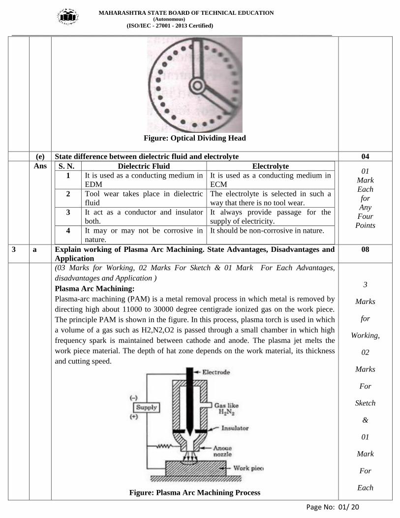
(2) Universal Dividing Head: The worm gear has 40 teeth and the worm has simple thread. Crank is directly attached with the
worm. If we revolve crank by 40 revolutions the spindle attached with worm gear will revolve
by only one revolution and one complete turn of the crank will revolve the spindle only by 1/40th
revolution (turn). In order to turn the crank precisely a fraction of a revolution, an indexing plate
is used. An indexing plate is like a circular disc having concentric rings of different number of
equally spaced holes. Normally indexing plate is kept stationary by a lock pin. A spring
loaded pin is fixed to the crank which can be fixed into any hole of indexing plate. The
turning movement of the work piece is stably controlled by the movement of crank.
Figure: Universal Dividing Head
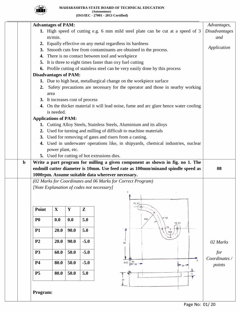
(3) Optical Dividing Head:
It is used for precise angular indexing during machining. The mechanism comprises a
worm gear which is keyed to the spindle and may be rotated by a worm. A circular glass
scale graduated in 10 division is rigidly mounted on the worm wheel. Any movement of
the spindle effected by rotating the worm is read off by means of a microscope fitted on
the dividing head body, the eye piece has a scale having 60 divisions & each division is
equivalent to 1’ movement of circular scale
MAHARASHTRA STATE BOARD OF TECHNICAL EDUCATION (Autonomous)
(ISO/IEC - 27001 - 2013 Certified)
__________________________________________________________________________________________________
Page No: 01/ 20
Figure: Optical Dividing Head
(e) State difference between dielectric fluid and electrolyte 04
Ans S. N. Dielectric Fluid Electrolyte
1 It is used as a conducting medium in
EDM
It is used as a conducting medium in
ECM
2 Tool wear takes place in dielectric
fluid
The electrolyte is selected in such a
way that there is no tool wear.
3 It act as a conductor and insulator
both.
It always provide passage for the
supply of electricity.
4 It may or may not be corrosive in
nature.
It should be non-corrosive in nature.
01
Mark
Each
for
Any
Four
Points
3 a Explain working of Plasma Arc Machining. State Advantages, Disadvantages and
Application
08
(03 Marks for Working, 02 Marks For Sketch & 01 Mark For Each Advantages,
disadvantages and Application )
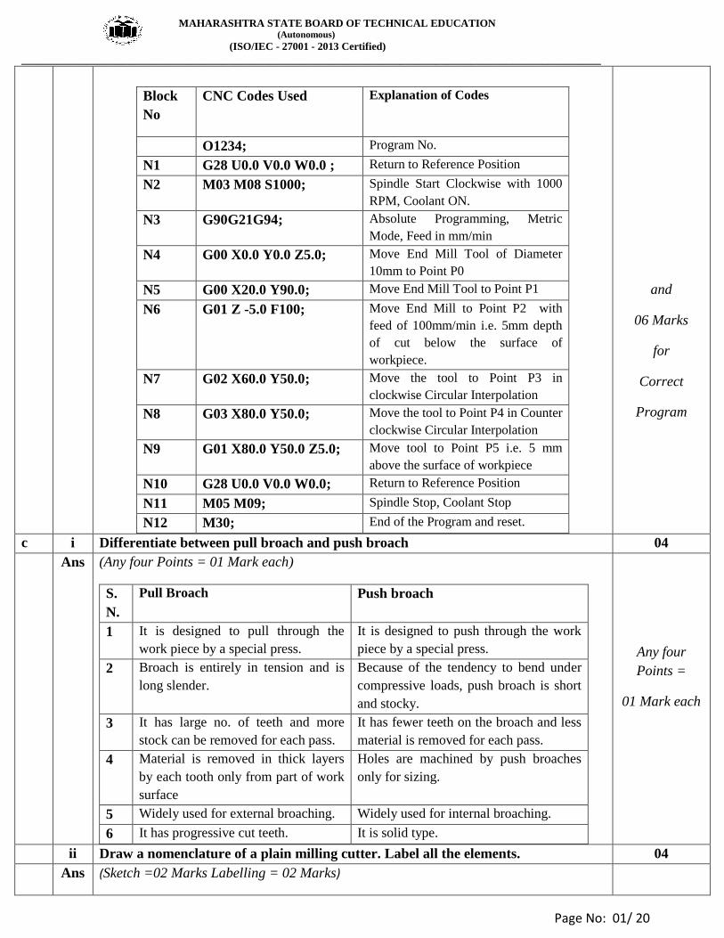
Plasma Arc Machining:
Plasma-arc machining (PAM) is a metal removal process in which metal is removed by
directing high about 11000 to 30000 degree centigrade ionized gas on the work piece.
The principle PAM is shown in the figure. In this process, plasma torch is used in which
a volume of a gas such as H2,N2,O2 is passed through a small chamber in which high
frequency spark is maintained between cathode and anode. The plasma jet melts the
work piece material. The depth of hat zone depends on the work material, its thickness
and cutting speed.
Figure: Plasma Arc Machining Process
3
Marks
for
Working,
02
Marks
For
Sketch
&
01
Mark
For
Each
MAHARASHTRA STATE BOARD OF TECHNICAL EDUCATION (Autonomous)
(ISO/IEC - 27001 - 2013 Certified)
__________________________________________________________________________________________________
Page No: 01/ 20
Advantages of PAM:
1. High speed of cutting e.g. 6 mm mild steel plate can be cut at a speed of 3
m/min.
2. Equally effective on any metal regardless its hardness
3. Smooth cuts free from contaminants are obtained in the process.
4. There is no contact between tool and workpiece
5. It is three to eight times faster than oxy fuel cutting
6. Profile cutting of stainless steel can be very easily done by this process
Disadvantages of PAM:
1. Due to high heat, metallurgical change on the workpiece surface
2. Safety precautions are necessary for the operator and those in nearby working
area
3. It increases cost of process
4. On the thicker material it will lead noise, fume and arc glare hence water cooling
is needed.
Applications of PAM:
1. Cutting Alloy Steels, Stainless Steels, Aluminium and its alloys
2. Used for turning and milling of difficult to machine materials
3. Used for removing of gates and risers from a casting.
4. Used in underwater operations like, in shipyards, chemical industries, nuclear
power plant, etc.
5. Used for cutting of hot extrusions dies.
Advantages,
Disadvantages
and
Application
b Write a part program for milling a given component as shown in fig. no 1. The
endmill cutter diameter is 10mm. Use feed rate as 100mm/minand spindle speed as
1000rpm. Assume suitable data wherever necessary.
08
(02 Marks for Coordinates and 06 Marks for Correct Program)
[Note Explanation of codes not necessary]
Program:
Point X Y Z
P0 0.0 0.0 5.0
P1 20.0 90.0 5.0
P2 20.0 90.0 -5.0
P3 60.0 50.0 -5.0
P4 80.0 50.0 -5.0
P5 80.0 50.0 5.0
02 Marks
for
Coordinates /
points
MAHARASHTRA STATE BOARD OF TECHNICAL EDUCATION (Autonomous)
(ISO/IEC - 27001 - 2013 Certified)
__________________________________________________________________________________________________
Page No: 01/ 20
Block
No
CNC Codes Used Explanation of Codes
O1234; Program No.
N1 G28 U0.0 V0.0 W0.0 ; Return to Reference Position
N2 M03 M08 S1000; Spindle Start Clockwise with 1000
RPM, Coolant ON.
N3 G90G21G94; Absolute Programming, Metric
Mode, Feed in mm/min
N4 G00 X0.0 Y0.0 Z5.0; Move End Mill Tool of Diameter
10mm to Point P0
N5 G00 X20.0 Y90.0; Move End Mill Tool to Point P1
N6 G01 Z -5.0 F100; Move End Mill to Point P2 with
feed of 100mm/min i.e. 5mm depth
of cut below the surface of
workpiece.
N7 G02 X60.0 Y50.0; Move the tool to Point P3 in
clockwise Circular Interpolation
N8 G03 X80.0 Y50.0; Move the tool to Point P4 in Counter
clockwise Circular Interpolation
N9 G01 X80.0 Y50.0 Z5.0; Move tool to Point P5 i.e. 5 mm
above the surface of workpiece
N10 G28 U0.0 V0.0 W0.0; Return to Reference Position
N11 M05 M09; Spindle Stop, Coolant Stop
N12 M30; End of the Program and reset.
and
06 Marks
for
Correct
Program
c i Differentiate between pull broach and push broach 04
Ans (Any four Points = 01 Mark each)
S.
N.
Pull Broach Push broach
1 It is designed to pull through the
work piece by a special press.
It is designed to push through the work
piece by a special press.
2 Broach is entirely in tension and is
long slender.
Because of the tendency to bend under
compressive loads, push broach is short
and stocky.
3 It has large no. of teeth and more
stock can be removed for each pass.
It has fewer teeth on the broach and less
material is removed for each pass.
4 Material is removed in thick layers
by each tooth only from part of work
surface
Holes are machined by push broaches
only for sizing.
5 Widely used for external broaching. Widely used for internal broaching.
6 It has progressive cut teeth. It is solid type.
Any four
Points =
01 Mark each
ii Draw a nomenclature of a plain milling cutter. Label all the elements. 04
Ans (Sketch =02 Marks Labelling = 02 Marks)

MAHARASHTRA STATE BOARD OF TECHNICAL EDUCATION (Autonomous)
(ISO/IEC - 27001 - 2013 Certified)
__________________________________________________________________________________________________
Page No: 01/ 20
Figure : Plain Milling Cutter
Sketch =02
Marks
Labelling =
02 Marks
4 a Attempt any THREE of the following 12
i Explain with neat sketch gear hobbing process 04
Ans (02 Marks For Sketch & 02 Marks For Explanation)
Figure: Gear Hobbing
In this process of gear generating a tool is used known as hob. Hob teeth are shaped to
match the tooth space and are interrupted with grooves to provide cutting surfaces. It
rotates about an axis normal to that of the gear blank, cutting into the rotating blank to
generate the teeth as shown in figure.
It is the most accurate of the roughing processes since no repositioning of tool or blank
is required and each tooth is cut by multiple hob-teeth, averaging out any tool errors.
Excellent surface finish is achieved by this method and it is widely used for production
of gears.
02 Marks
For Sketch
&
02 Marks
For
Explanation
ii What is gear shaving? Explain with sketch 04
Ans (02 Marks for Explanation and 02 Marks for figure)
Gear Shaving Process:
Gear shaving process can be linear or rotary. In the linear type rack type cutter is used.
While rotary method employs a pinion cutter. The cutter teeth are serrated to form a
series of cutting edges. To obtained relative sliding action between the tooth profile the
work gear and shaving cutter are set up in the gear shaving machine with cross axes.
02 Marks
for
Explanation
and
02 Marks
MAHARASHTRA STATE BOARD OF TECHNICAL EDUCATION (Autonomous)
(ISO/IEC - 27001 - 2013 Certified)
__________________________________________________________________________________________________
Page No: 01/ 20
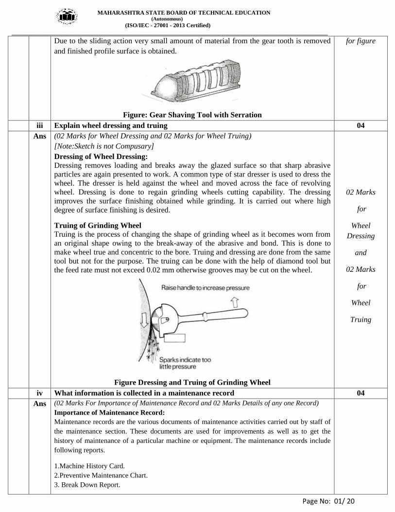
Due to the sliding action very small amount of material from the gear tooth is removed
and finished profile surface is obtained.
Figure: Gear Shaving Tool with Serration
for figure
iii Explain wheel dressing and truing 04
Ans (02 Marks for Wheel Dressing and 02 Marks for Wheel Truing)
[Note:Sketch is not Compusary]
Dressing of Wheel Dressing:
Dressing removes loading and breaks away the glazed surface so that sharp abrasive
particles are again presented to work. A common type of star dresser is used to dress the
wheel. The dresser is held against the wheel and moved across the face of revolving
wheel. Dressing is done to regain grinding wheels cutting capability. The dressing
improves the surface finishing obtained while grinding. It is carried out where high
degree of surface finishing is desired.
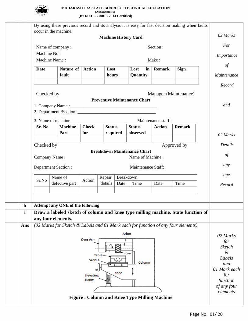
Truing of Grinding Wheel Truing is the process of changing the shape of grinding wheel as it becomes worn from
an original shape owing to the break-away of the abrasive and bond. This is done to
make wheel true and concentric to the bore. Truing and dressing are done from the same
tool but not for the purpose. The truing can be done with the help of diamond tool but
the feed rate must not exceed 0.02 mm otherwise grooves may be cut on the wheel.
Figure Dressing and Truing of Grinding Wheel
02 Marks
for
Wheel
Dressing
and
02 Marks
for
Wheel
Truing
iv What information is collected in a maintenance record 04
Ans (02 Marks For Importance of Maintenance Record and 02 Marks Details of any one Record)
Importance of Maintenance Record:
Maintenance records are the various documents of maintenance activities carried out by staff of
the maintenance section. These documents are used for improvements as well as to get the
history of maintenance of a particular machine or equipment. The maintenance records include
following reports.
1.Machine History Card.
2.Preventive Maintenance Chart.
3. Break Down Report.
MAHARASHTRA STATE BOARD OF TECHNICAL EDUCATION (Autonomous)
(ISO/IEC - 27001 - 2013 Certified)
__________________________________________________________________________________________________
Page No: 01/ 20
By using these previous record and its analysis it is easy for fast decision making when faults
occur in the machine.
Machine History Card
Name of company : Section :
Machine No :
Machine Name : Make :
Checked by Manager (Maintenance)
Preventive Maintenance Chart
1. Company Name :_______________________________________
2. Department /Section :___________________________________
3. Name of machine : Maintenance staff :
Sr. No Machine
Part
Check
for
Status
required
Status
observed
Action Remark
Checked by Approved by
Breakdown Maintenance Chart
Company Name : Name of Machine :
Department Section : Maintenance Staff:
Sr.No Name of
defective part Action
Repair
details
Breakdown
Date Time Date Time
Date Nature of
fault
Action Lost
hours
Lost in
Quantity
Remark Sign
02 Marks
For
Importance
of
Maintenance
Record
and
02 Marks
Details
of
any
one
Record
b Attempt any ONE of the following
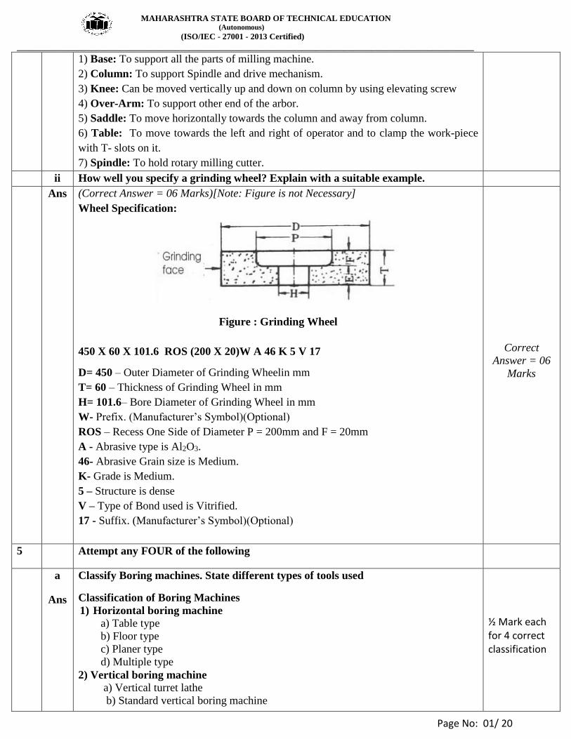
i Draw a labeled sketch of column and knee type milling machine. State function of
any four elements.
Ans (02 Marks for Sketch & Labels and 01 Mark each for function of any four elements)
Figure : Column and Knee Type Milling Machine
02 Marks
for
Sketch
&
Labels
and
01 Mark each
for
function
of any four
elements
MAHARASHTRA STATE BOARD OF TECHNICAL EDUCATION (Autonomous)
(ISO/IEC - 27001 - 2013 Certified)
__________________________________________________________________________________________________
Page No: 01/ 20
1) Base: To support all the parts of milling machine.
2) Column: To support Spindle and drive mechanism.
3) Knee: Can be moved vertically up and down on column by using elevating screw
4) Over-Arm: To support other end of the arbor.
5) Saddle: To move horizontally towards the column and away from column.
6) Table: To move towards the left and right of operator and to clamp the work-piece
with T- slots on it.
7) Spindle: To hold rotary milling cutter.
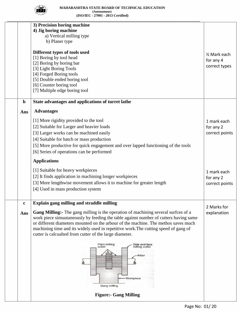
ii How well you specify a grinding wheel? Explain with a suitable example.
Ans (Correct Answer = 06 Marks)[Note: Figure is not Necessary]
Wheel Specification:
Figure : Grinding Wheel
450 X 60 X 101.6 ROS (200 X 20)W A 46 K 5 V 17 D= 450 – Outer Diameter of Grinding Wheelin mm
T= 60 – Thickness of Grinding Wheel in mm
H= 101.6– Bore Diameter of Grinding Wheel in mm
W- Prefix. (Manufacturer’s Symbol)(Optional)
ROS – Recess One Side of Diameter P = 200mm and F = 20mm
A - Abrasive type is Al2O3.
46- Abrasive Grain size is Medium.
K- Grade is Medium.
5 – Structure is dense
V – Type of Bond used is Vitrified.
17 - Suffix. (Manufacturer’s Symbol)(Optional)
Correct
Answer = 06
Marks
5 Attempt any FOUR of the following
a
Ans
Classify Boring machines. State different types of tools used
Classification of Boring Machines
1) Horizontal boring machine a) Table type
b) Floor type
c) Planer type
d) Multiple type
2) Vertical boring machine a) Vertical turret lathe
b) Standard vertical boring machine
½ Mark each for 4 correct classification
MAHARASHTRA STATE BOARD OF TECHNICAL EDUCATION (Autonomous)
(ISO/IEC - 27001 - 2013 Certified)
__________________________________________________________________________________________________
Page No: 01/ 20
3) Precision boring machine
4) Jig boring machine a) Vertical milling type
b) Planer type
Different types of tools used
[1] Boring by tool head
[2] Boring by boring bar
[3] Light Boring Tools
[4] Forged Boring tools
[5] Double ended boring tool
[6] Counter boring tool
[7] Multiple edge boring tool
½ Mark each for any 4 correct types
b
Ans
State advantages and applications of turret lathe
Advantages
[1] More rigidity provided to the tool
[2] Suitable for Larger and heavier loads
[3] Larger works can be machined easily
[4] Suitable for batch or mass production
[5] More productive for quick engagement and over lapped functioning of the tools
[6] Series of operations can be performed Applications
[1] Suitable for heavy workpieces
[2] It finds application in machining longer workpieces
[3] More lengthwise movement allows it to machine for greater length
[4] Used in mass production system
1 mark each for any 2 correct points
1 mark each for any 2 correct points
c
Ans
Explain gang milling and straddle milling
Gang Milling:- The gang milling is the operation of machining several surfces of a
work piece simuutaneously by feeding the table against number of cutters having same
or different diameters mounted on the arbour of the machine. The methos saves much
machining time and its widely used in repetitive work.The cutting speed of gang of
cutter is calcualted from cutter of the large diameter.
Figure:- Gang Milling
2 Marks for explanation

MAHARASHTRA STATE BOARD OF TECHNICAL EDUCATION (Autonomous)
(ISO/IEC - 27001 - 2013 Certified)
__________________________________________________________________________________________________
Page No: 01/ 20
Straddle Milling:- The straddle is the operation of production of flat vertical surfaces
on the both sides of the workpiece by using two side cutters by providinbg coller
between them for spacing. The straddle milling is very commonly used to produce
square or hexagonal surfaces.
Figure:- Straddle Milling
2 Marks for explanation
d
Ans
What is centre less grinding? Explain any one with neat sketch
Centreless grinding is a method of grinding exterior cylindrical, tapered and formed
surfaces that are not held and rotated on centres.
The principle elements of the grinders are,
1) Grinding wheel
2) Work
3) Regulating wheel
4) Work rest
An angular adjustment of 0 to 100is provided In the machine by tilting regulating wheel.
The actual feed can be calculated by,
S = πdn sinἀ
Where,
S= Feed in mm/min, N = rpm
d= dia. Of regulating wheel, ἀ= angle of inclination if any
Figure: Centreless Grinding
Both the wheels are rotated in the same direction. The work rest is located between the
wheels, the work is rest upon the work rest and together with regulating wheel fed
forward, forcing the work against grinding wheel. The axial movement of the work
past the grinding wheel is obtained by tilting regulating wheel at a slight angle from
horizontal.
1 Mark for definition
2 Marks for explanation
&
1 Mark for diagram

MAHARASHTRA STATE BOARD OF TECHNICAL EDUCATION (Autonomous)
(ISO/IEC - 27001 - 2013 Certified)
__________________________________________________________________________________________________
Page No: 01/ 20
e
Ans
Explain the working principle of honing. State its applications
Principle
Honing is a grinding or a abrading process mostly finishing round holes by
means of bonded abrasive stones called hones. Materials ranged from plastics, silver,
aluminium, brass and cast iron can be honed easily.
Applications
1) Finishing automobile crankshafts journals
2) Finishing round holes
3) Finishing hollow cylindrical parts
2 Marks for principle
&
1 Mark each for 2 correct applications
f
Ans
What are different types maintenance? Give suitable example of each
Types of Maintenance
1) Preventive maintenance:- Cleaning, Lubrication, Replacement of consumables
like belts, bearings, gaskets etc, Reconditioning
2) Predictive maintenance:- Changing of oil in car, replacement of bearing due to
noise
3) Breakdown maintenance:- Machine tool failure on production floor
4) Corrective maintenance:- Replacement of chain due to noise, replacement of
bearing due to failure
5) Scheduled maintenance:- Overhauling of machine tool, Servicing of motor bike
01 Mark each for any 4 correct point and Example
6 Attempt any FOUR of the following 16
a
Ans
Explain the concept of Dry run and Jog mode
Dry Run
A key that activates the dry run feature on a CNC machine. The dry run function checks
a program quickly without cutting parts.
A dry run (or a practice run) is a testing process where the effects of a possible failure
are intentionally mitigated.
Example:- An aerospace company may conduct a "dry run" test of a jet's new pilot
ejection seat while the jet is parked on the ground, rather than while it is in flight.
Objectives:-
1) to verify the correctness of the setup with proven CNC programs
2) to find serious mistakes that still exist in the program
2 Marks for Explanation
Figure: Honning Tool

MAHARASHTRA STATE BOARD OF TECHNICAL EDUCATION (Autonomous)
(ISO/IEC - 27001 - 2013 Certified)
__________________________________________________________________________________________________
Page No: 01/ 20
Jog Mode
The area of the machine control that allows an operator to move a selected axis. Jog keys
are often called axis direction keys.
In JOG mode, the continuous movement of a tool in a direction along a selected axis.
Jog mode is mostly used to travel the CNC machine table slide for movement of table
along X-axis and Z-axis.
CNC machine works manually like conventional machines.
2 Marks for Explanation
b
Ans
Explain how a capstan lathe is different from a simple lathe
It is production lathe used to manufacture any number of identical pieces in the
minimum time. The capstan and turret lathe consists of a bed, all geared headstock and a
saddle on which a four station tool post is mounted to hold four different tools. A series
of operation can be perform such as turning, drilling, boring, reaming etc
[1] The turret of capstan lathe is mounted on slides on the saddle
[2] Less rigidity provided to the tool
[3] High production rate as fast cut is possible
4 Marks for explanation
c
Ans
Sketch and label basic parts of a horizontal broaching machine
Figure: Horizontal Broaching Machine.
3 Marks for neat sketch
& 1 Mark for Correct labeling
d
Ans
Enlist grinding wheel safety precautions
Safety Precautions:- 1) Ensure proper mounting of wheel
2) Ensure fitting of wheel
3) Check Proper balancing
4) Check guarding arrangement on machine for wheel.
5) Check proper truing of grinding wheel
1 Mark each for any 4 correct points
MAHARASHTRA STATE BOARD OF TECHNICAL EDUCATION (Autonomous)
(ISO/IEC - 27001 - 2013 Certified)
__________________________________________________________________________________________________
Page No: 01/ 20
e
Ans
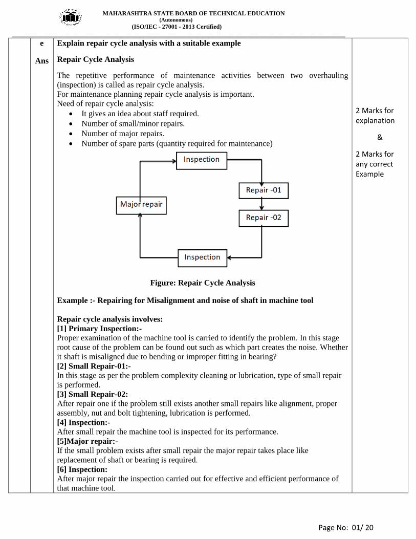
Explain repair cycle analysis with a suitable example
Repair Cycle Analysis
The repetitive performance of maintenance activities between two overhauling
(inspection) is called as repair cycle analysis.
For maintenance planning repair cycle analysis is important.
Need of repair cycle analysis:
It gives an idea about staff required.
Number of small/minor repairs.
Number of major repairs.
Number of spare parts (quantity required for maintenance)
Figure: Repair Cycle Analysis
Example :- Repairing for Misalignment and noise of shaft in machine tool
Repair cycle analysis involves:
[1] Primary Inspection:-
Proper examination of the machine tool is carried to identify the problem. In this stage
root cause of the problem can be found out such as which part creates the noise. Whether
it shaft is misaligned due to bending or improper fitting in bearing?
[2] Small Repair-01:-
In this stage as per the problem complexity cleaning or lubrication, type of small repair
is performed.
[3] Small Repair-02:
After repair one if the problem still exists another small repairs like alignment, proper
assembly, nut and bolt tightening, lubrication is performed.
[4] Inspection:-
After small repair the machine tool is inspected for its performance.
[5]Major repair:-
If the small problem exists after small repair the major repair takes place like
replacement of shaft or bearing is required.
[6] Inspection:
After major repair the inspection carried out for effective and efficient performance of
that machine tool.
2 Marks for explanation
&
2 Marks for any correct Example