191 r ·192r ·193r · 200r - vintage sno · moteur type 200 r manter le dispositif de blocage du...
TRANSCRIPT

ENGINE MODELS
191 R ·192R ·193R · 200R
INSTRUCTIONS FOR ASSEMBLY AND DISASSEMBLY
(lntructions pour le Montage et Demontage du Moteur)
ISSUE MM· 323
... . ..
WISCONSIN r:Ji WISCONSIN- HIRTH Snowmobile and Vehicle Engines
MOTOR

Technical Data
Enginft Output:
Direction of rotation:
Bore:
Stroke:
Type 191 R ...
19 hp (DIN) at 5500 rev / min
192 R ...
20.5 hp (D IN) at 5750 rev/ min
counter clockwi!le, viewed towards P.T.O.
2.953" (75 mm) 3.031" (77 mm)
2.68" (68 mm) 2.68'· (68 mm)
193 R ... 200 R ...
19 hp (DIN) 23 hp (DIN) at 5000 rev / min at 5250 rev/min
2.913" (74 mm) 3.169" (80.5 mm)
2.68" (68 mm) 2.87" (73 mm)
Piston displacement: 18.3 cu. in. (300 cc.) 19.34 cu. in. (317 cc.) 17.82 cu. in. (292 cc.) 22.7" (372 cc.)
Point gap: .016 ± .002" (0.4.:!:0.05 mm)
Ignition timing: Retarded: 4 t 3° BTDC = .004 I· .0085" (0.1 +0.22 mm)
Spark plug
Advanced: 22+ 31) BTDC = .122+.035" (3.1 -+-0.9 mm)
for normal operation: M 225 T 1 Bosch
for heavy-duty operation: M 225 T 1 Bosch
.016::::: .002" (0.4±0.05 mm)
4+ 3 BTDC = .004 + .0085" (0.1 '1- 0.22 mm)
22-:-3:. BTDC - .122+.035" (3.1 + 0.9 mm)
M 225 T 1 Bosch
M 225 T 1 Bosch
.016 ± .002" (0.4±0.05 mm)
4+ 3° BTDC .004+ .0085"
(0.1 +0.22 mm)
22+3-> BTDC =.122 .035" (3.1+0.9 mm)
M 225 T 1 Bosch
M 225 T 1 Bosch
.016 ± .002" (0.4::!:0.05 mm)
4+3° BTDC .0043+ .009"
(0.1 1+0.23 mm)
22+3 BTDC - .13+.039" (3.3+ 1.0 mm)
M 225 T 1 Bosch
M 240 T 1 Bosch
Spark plug gap: .02+.004" (0.5 ·1 0.1 mm) .02 -1 .004" (0.5 + 0.1 mm) .02+.004" (0.5 0.1 mm) .02 f-.004" (0.5+0.1 mm)
Ignition system: Bosch dynamo magneto ignition with automatic advanced timing light power 40 Watt, 12 Volt or 75 Watt, 12 Volt
f
Disassembly of motor
Remove motor from apparatus. Attached parts, like muffler, carburettor, electric starter must be removed.
2. Screw assembly angle W 115 to tho drill holes of the base and clamp motor with angle into the vice.
Fanhousing
3. Lift off fanhousing after loosening the 4 hollow screws.
Flywheel
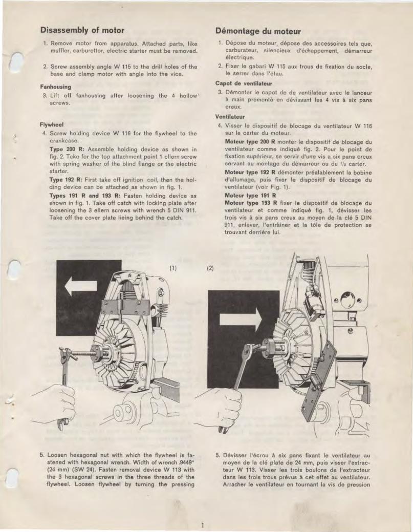
4. Screw holding device W 116 for the flywheel to the crankcase.
Type 200 R: Assemble holding device as shown in frg. 2. Take for the top attachment pomt 1 ellern screw with spring washer of the blind flange or the electric starter.
Type 192 R: First take off ignition coil, then the holding device can be attached, as shown in fig. 1.
Types 191 R and 193 R: Fasten holding device as shown in fig. 1. Take off catch with locking plate after loosening the 3 ellern screws with wrench 5 DIN 911. Take off the cover plate lieing behind the catch.
5. loosen hexagonal nut with which the flywheel is fastened with hexa,gonal wrench. W idth of wrench .9449" (24 mm) (SW 24). Fasten removal device W 113 with the 3 hexagonal screws in the three threads of the flywheel. loosen flywheel by turning the pressing
Demontage du moteur Depose du moteur, depose des accessoires tels que, carburateur, silencieux d'echappement, demarreur electnque.
2. Fixer le gabari W 115 aux trous do fixat ion du socle, le serrer dans l'ctau.
Capot de ventilateur
3. Demontcr le capo! de de ventilateur avec le lanceur a main premonte en devissant les 4 vis a six pans creux.
Ventilateur
4 Visser le drspositif de blocage du ventilateur W 116 sur le carter du moteur.
Moteur type 200 R manter le dispositif de blocage du ventilateur comme indique fig 2. Pour le point de fixation superieur, so servir d'une vis a six pans creux servant au montage du demarreur ou du 1/t carter.
Moteur type 192 R demonter prealablement Ia bobine d'allumage, puis fixer le dispositif de blocage du ventilateur (voir Fig. 1).
Moteur type 191 R Moteur type 193 R fixer le dispositif de blocage du ventilateur et comme indique fig. 1, devisser les trois vrs a six pans creux au moyen de Ia cle 5 DIN 911, enlever, l'entrainer et Ia tOle de protection se t rouvant derriere lui.
5. Devisser l'ecrou a six pans fixant le ventilateur au moyen de Ia c le plate de 24 mm, puis visser l'extracteur W 113. Visser les t ro is boulons de l 'extracteur dans les trois trous prevus a cet effet au ventilateur. Arracher le ventilateur en tournant Ia vis de pression

screw of device W 113 towards tho right side. Unscrew holding device so that the flywheel can be taken off.
Ignition
6. Take off sparkplug hood for sparkplug and screw out sparkplug.
191 R and 193 R: Loosen fastening clamp of ignition wire.
192 Rand 200 R: Loosen the 2 tapping screws with which the coil is fastened, if the coil was not removed before. Pull blue generator cable out of the plug con· nection with the coil. Best cut off plug from the generator wire and pull off protection sleeve. Pull generator cable through the upper rubbei socket in the housing. A drop of oi l in the rubber sockets makes the pulling through of the cables easier.
In all types of motors loosen the 3 fastening screws with which the armature plate is screwed to the housing. Take off the armature plate when doing this also pull out the wires.
Cylinder
7. 191 Rand 193 R: Loosen tapping screws with which air guide plate is fastened. Take off airguide plate by pulling it upward. Loosen screws or nuts with which the cyl inder head is fastened. Take off cylinder head with head gasket.
200 R: Unscrew the 4 hexagonal nuts with which tho cylinder is screwed to the crankcase. Use wrench SW 17. Lift off cylinder.
Piston
8. Remove safeties of gudgeon pin. Press out gudgeon pin with assembly pin.
Assembly pin 200 R: W 39/ 6 " 191 R " 192 R I w 39' 4
• " 193 R I If necessary slightly tap with a hammer, while dotng this hold piston with hand. Remove piston.
9. Push needle cage out of the small eye of the connecting rod. To keep it, best place it over the gudgeon pin.
O il seal
10. Turn motor in vice at 180 .
11. Make a hole in the covenng of the o il seal with a pointed tool. In doing so pay attention that the bearing lieing behind the covering, is not damaged. Then put a hook into the hole and pull out the oil seal.
Crankcase
12. Remove the exterior snap ring on the crankshaft with exterior snap ring pliers. With ellern wrench screw 5 Dl N 911 loosen the six screws with which crankcase and crankcase flange are screwed together.
2
de l 'extracteur dans le sens des aiguilles d'une montre. Devisser le dispositif de blocage afin de pouvoir retirer le ventilateur.
6. Allumage
Retirer le chapeau de Ia bougie et devisser Ia bougie.
191 Ret 193 R: Enlever Ia bride de fixat ion du fi l de bougie.
192 Ret 200 R: Devfsser les deux vis taraud fixant Ia bobine, a moins que cette derniere n'ait eta enlevee prealablement. Retirer le fil bleu de Ia prise dans Ia bobine, couper Ia languette de contact, sortir le manchon pare-pluie, retirer le fil du caoutchouc passe, cable une goutte d'huile faci litera !'operation.
Concerne tous les moteurs: Devisser les 3 vis fixant le plateau porte induits sortir le plateau avec les fils des conduites electriques.
Cylindre
7. 191 Ret 193 R: Devisser Ia vis taraud fixant le capot guide d'air, retirer ce dernier vers le haul. Devisser les ecrous ou les vis de fixation de Ia culasse retirer Ia culasse
200R:
Piston
ainsi que le joint de culasse. Devisser les 4 ecrous a six pans fixant le cylindre au carter au moyen de Ia cle plate de 17 mm. Deposer le cylindre.
8. Retirer Jes jones d'arrAt de l'axe de piston. Sortir J'axe de piston au moyen de Ia broche specialc. Broche- 200 R: W 39/ 6 Broche -191 R: 1
Broche ~ 192 R: Jl Broche -193 R:
W39/ 4
Au besoin maintenir le piston d'une main et en donnant des petits coups de marteau faciliter !'extraction. Enlever le piston.
9. Retirer le cage a aiguilles de l 'oeil du pied de bielle. Pour plus de surete, i f est preferable de Ia remettre de suite sur l'axe de piston.
Bague d'etancheite
10. Faire pivoter le moteur de 180° dans l'etau.
11 . A l'aide d'un pointeau, en veillant 'a ne pas abimer Je roulement, percer un trou dans Ia bague d'etancheite. Puis au moyen d'un crochet passe par ce trou. Retirer Ia bague d'etancheite.
Carter
12. Enlever Je circlips de l'axe du vilebrequin au moyen d'une pince a circlips exterieurs. Devisser les vis a six pans creux au moyen de Ia cle male a six pans 5 DIN 911.
..

(' (
t
I .. ..
13. Screw removal device W 119 to the crankcase flange. Put pressure part W 105/ 4 into the boring of the c rankshaft and by turning the pressure screw press crankcase with crankshaft away from the crankcase flange. After this remove device W 119 (fig. 3).
Crankshaft
14. The removal of the crankshaft from the crankcase i:; done in the following way: Heat ·the crankcase on the ignition side to 212° to utmost 285° F (100-140° centigrades). Best use a blow forch for it (fig. 4).
3
13. Visser le dispositif de demontage du vilebrequin W 119 sur le carter. Poser Ia piece d'appui W 105/ 4 dans le creux de l'axe du vi lebrequin, serrer Ia vis de pression extraire le vilebrequin tout en separant les 1/ 2 carters. Fig. 3.
(3)
Vilebrequin
14. Sortir le vilebrequin du 1/t carter en procedant comme suit: Chauffer le carter c6te volant magnetique a 212° maximum 285° F {100-140° C). Se servir de preference d'une lampe a souder. Fig. 4.
(4)
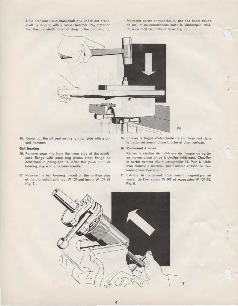
Hold crankcase and crankshaft and knock out crankshaft by tapping with a rubber hammer. Pay attention that the cranshaft does not drop to the floor (fig. 5).
15. Knock out the oil seal on the ignition side with a pin and hammer.
Ball bearing
16. Remove snap ring from the inner side of the crank· case flange with snap ring pliers. Heat flange as described in paragraph 14. After this push out ball bearing, e.g. with a hammer handle.
17. Remove the ball bearing placed on the ignition side of the crankshaft with tool W 107 and insets W 107/15 (fig. 6).
4
Maintenir carter et vilebrequin; par des petits coups de maillet en caoutchouce sortir le vilebrequin. Veiller a ce qu'il ne tombe a terre. Fig. 5.
{5)
15. Enlever Ia bague d'etancheite de son logement dans le carter au moyen d'une broche et d'un marteau.
16. Roulement a billes
Retirer le circlips de l 'interieur du flasque du carter au moyen d'une pince a circlips interieurs. Chauffer le carter comma decrit paragraphe 14. Puis a l'aide d'un manche a marteau, par exemple chasser le roulement vers l'exterieur.
17. Extraire le roulement cote volant magnetique au moyen de l'extracteur W 107 et accessoire W 107/15. Fig. 6.
(6)

,--. (
r
•
18. Clean parts of motor with washing gasoline. Carefully scrape off all residues of packing material on the sealing surface.
19. Replace defective parts.
Motor assembly Ball bearing
1. Place snap ring into the P.T.O. side of the crankcase flange. Heat flange to about 212 to at the utmost 285" F (100-140° centigrades). Press in ball bearing from the inside until it touches the snap ring. Install $CCond snap ring.
2. Screw crankcase flange to assembly angle W 115 and put it into vice (fig. 7).
Crankshaft
3. Push crankshaft with pivot on the P.T.O. side through the bearing. Screw pin of the tool W 112 into the internal thread of the crankshaft. Push feeding-in tool W 112 over the pin until it touches the ball bearing. After this retract the tool as far as H is necessary to push the peg through tool and pin. Pull crankshaft by means of the two levers of the tool to the end of the stroke of the device. Then put the pin into the next hole in the direction towards the f lange and repeat this action until crankweb touches the bearing. During the whole action pay attention that the connecting rod is standing straight upright, since otherwise it may be bent (see fig. '7).
4. Screw off tool W 112 and install snap ring on the crankshaft on the P.T.O. side.
5. Slightly oil radial seal on exterior and interior diameter and push it towards the bearing. Press the
5
18. Nettoyer toutes les pieces du moteur a !'essence. Enlever soigneusement les restes de joints ou de pate d'etancheite sur Ia surface des joints.
19. Toute piece detectueuse est a remplacer.
Remontage du moteur Roulement a billes 1. Remonter le circlips dans Ia bride du 1/~ carter cOte
prise de force. Chauffer le 1/ 2 carter a environ 212° max. 285° F (100-140° C). Monter le roulement dans son logement jusqu'a ce qu' il vienne buter contre le circlips. Monter le 2e circlips.
2. Visser le' 1/ 2 carter sur le gabari W 115 le serrer dans l'etau. Fig. 7.
(7)
Vilebrequin
3. Passer le bout d'arbre de fa prise de force dans Ia bague interieure du roulement. Visser l'appareil de montage W 112 dans le pas de vis du vifebrequin, pousser l 'appareil de montage jusqu'a ce qu'if vienne buter contre le roulement, puis revenir en arriere de fac;on a pouvoir passer Ia cheville dans le trou de l'appareil de montage et celui correspondant de l'axe. A !'aide des deux leviers introduire le vi lebrequin jusqu'a fin de course de l'appareil. Enlever Ia cheville et Ia replacer dans le trou suivant; continuer le processus de montage jusqu'a ce que le vilebrequin vienne buter contre le roulement a billes. Ce faisant veiller constamment a ce que Ia bielle soit orientee verticalement vers le haut, si non elle risque d'etre endommagee. Fig. 7.
4. Enlever l'appareil de montage W 112 et mettre le circlips en place sur l'arbre cOte ptise de force.
5. Huiler legerement Ia portae interieure et exterieure de Ia bague d'etancheite Ia pousser contre le roule-

radial seal with pressure disk W 37t 8 and tool W 112 until it touches the snap ring. The forcing in is done as described in paragraph 3 (fig. 8).
Cr•nkcase
6. Turn crankcase flange in the vice 180° around. 7. Put sealing material on the sealing surface on the
crankshaft flange. 8. Heat up the half of the crankcase lying towards the
Ignition to 212 to at the utmost 285° F (10Q-140° centigrades) and then put on the flange. Pay attention to the fitting pins. Push the second ball bearing on the crankshaft and push it with tool W 112 to the collar on the crankshaft (for action see paragraph 3)r Take off device and place snap rmg into the housing (fig. 9.).
ment. Puis au moyen de Ia plaque W 37/ 8 et de l'appareil de montage W 112. Presser Ia bague d'etancheite dans son logement jusqu'a ce qu'elle vienne buter contre le fond, suivre le processus de montage decrit. Paragraphe 3 (Fig. 8).
(8}
Carter
6. Faire pivoter le 1/! carter de 180° et reserrer le gabari dans l'etau.
7. Enduire toute Ia surface de jointure du carter d'une solution d'etancheite.
8. Chauffer le 1/! carter cOte allumage a 212-285° F (10Q-140° C). Puis le mettre en place sur le 1/! carter oppose, en veillant aux gousons-guides. Monter le 2e roulement sur le vilebrequin et a l'aide de l'appareil de montage W 112. Pousser le roulement jusqu'a Ia collerette du vilebrequin (processus de montage voir paragraphe 3). Devisser l'appreil de montage W 112, mettre le circlips en place sur l'arbre. Fig. 9.
(9)
4

•
9. Oil radial seal. Push it with sealing lip to bearmg over assembly socket W 1 H. After this put in radial seal with tool W 112 and pressure plate W 37/ 8 (fig. 1 0).
10. Screw together crankcase and crankcase flange with 6 ellern screws. Attention: Always put new flat washers under the hexagon nuts so that the crankcase is satisfactorily sealed. Tighten screws with 6.5• 1•5 ftlbs (0.9·0·2 kpm).
Piston
11. Put on cyinder base gasket. Push needle c~ge mto the small eye of the connecting rod. Oil connecting rod bearing and needle cage with good motor oil. Put in snap ring for gudgeon pin pointing towards the ignition. On the top of the piston an arrow is marked, pointing in the direction of the exhaust. By this the correct position of the piston can be found at any time. Put piston over the small eye of the connecting rod and push gudgeon pin with assembling pin until it touches snap ring. (Fitting assembling pins see disassembly of motor, paragraph 8). Install the second snap ring (fig. 11 ).
7
Piston
9. Huiler Ia bague d'etancheite, Ia passer par dessus Ia douille de montage W 114, Ia levre d'tHancheite, tournee vers le roulement, puis a l'aide de Ia plaque W 37/ 8 et au moyen de l'appareil de montage W 112, Ia mettre en place. Fig. 10.
10. Visser le 1/ t carter a flasque sur le ' /! carter au moyen de 6 vis a stx pans creux. Attention: Se servir de rondalles joints neuves pour etre assure d'avoir une etancheite parfaite. Sorrer les vis a 6,5· ' ·5 ftlb (0,9+0·2 kpm).
11. Poser le joint de Ia base du cylindre, passer Ia douille a aigutlles dans l'oeil du pied de bielle. Huiler avec une bonne huile le roulement de Ia tete de bielle, ainsi que Ia douille a aiguilles. Monter le jonc d'arret de l'axe de piston cOte volant magntHique. l'axe de piston porte une fleche qu i devra toujours !Hre orientee vers !'admission ainsi Ia bonne position du piston est facilement controlable a tout moment. Passer le piston sur le pied de bielle et a !'aide de Ia broche de montage pousser l 'axe de piston jusqu'a ce qu'il vienna buter contra le jonc d'arret d'axe. Broche de montage appropriee. Voir demontage du moteur. Point 8). Monter le deuxieme jonc d'arret d'axe. Fig. 11 .
(11)

Cautionally clean carbonised piston ring grooves. Best use for it a piece of a piston ring ground down on one side.
Cylinder and cylinder head
12. Push wooden piston support W 24 under the piston. Oil piston skirt and cylinder bore with motor oil. Turn piston rings by hand in such a way that the rings are lieing between the guard pins. Press together rings with piston ring pliers W 108 and clamping collar. Necessary piston ring clamping collars 191 Rand 193 R: W 108/15 192 R: W 108/16 200 R: W 108 ' 17
Push cylinder over p•ston, in doing so pay attention, that the arrow on the piston head points toward the exhaust passage of the cylinder (fig. 12).
13. 200 R: Tighten down cylinder with 4 washers and nuts crosswise with a fork wrench SW 17 with 33•3 ftlbs (4.6.0 •kpm). Put cylinder head gasket in place and put on cylinder head. Tighten cylinder head with 8 ellern screws and washers with hexagonal spanner 6 DIN 911, 16.5+0•2 ft lbs (2.3•0•3 kpm).
191, 192 and 193 R: Put cylinder head gasket in place and put on cylinder head. Tighten down cylinder and cylinder head crosswise with 4 washers and nuts 19.5•2 ftlbs = 2.7•0•3 kpm.
Attention: Always replace cylinder head gasket in order to avoid gas blow of the cylinder head! When cylinder head is put on pay attention that the fins are parallel to the axis of the crankshaft.
Au cas ou les rainures des segments seraient calaminees, les nettoyer avec precaution. Le mieux est d'utiliser un morceau de segment rectifie a Ia meule a l'une de ses extremites.
Cylindre et culasse
12. Placer le piston sur le support en bois W 24. Huiler les parois du cylindre et le corps du piston. Tourner les segments a Ia main pour faire correspondre les ergots avec les goupilles des rainures du piston. Serrer les segments a l'aide de Ia pince a segments. W 108. Pinces a segments appropriees 191 Ret 193 R W 108/15 192 R W 108/ 16 200 R W 108/ 17
Passer le cylindre sur le piston, veiller a ce que Ia fleche sur le fond du piston so it 01 ientee vers le t::anal d 'aspiration. Fig. 12.
(12)
13. 200 R: Proceder par serrage en croix des 4 ecrous au moyen de Ia cle plate de 17 (SW 17) serrer a 33•3 ftlb (4,6 o.• kpm). Mettre le joint de culasse en place, monter Ia culasse, Ia serrer a l'aide des 8 vis a six pans creux au moyen de Ia cle 6 DIN 911. Serrer A 16,5•2 ftlb (2,3+0·3 kpm).
191, 192 et 193 R: Mettre le joint de culasse en place, monter Ia culasse, serrer les 4 ecrous en procedant par serrage en croix serrer. 19,5"2 ftlb (2,7.o·3 kpm).
Attention: Monter un joint de culasse neuf afin d'eviter une perle de compression. Au montage de Ia culasse veiller a ce que les ailettes de refroidissement soient paralleles a l'axe du vilebrequin.
,. r

INSTRUCTIONS FOR ENGINE PROTECTION
Under certam duty conditions present-day fuels leave harmful residues (acids) in the engine. These residues may lead to senous corrosion and heavy damage {corroded bearmgs) when the engine is shut sown for a considerable penod. Enc•nes with low total running ttmes are particularly liable to this trouble. For thts reason HIRTH enganes are supplied wtth scavengtng oil after the final tests. We strongly recommend to repeat these protective measures if it is likely that the engine will remain unused for some time
t after it was operated. In any case the engines shall be protected anew after the operation season, that means before being laid up .
•
J •
For protection of the engine the following procedure is adopted:
1. Clean the engine at the outside.
2 Remove the spark plug.
3. Set the p1ston at bottom dead center. To do this the ptston head 1s contacted with a screwdnvcr or s1mi lor tool through the spark plug orihce and the engine is slowly turned over until the piston has reached tts I owest pos1taon.
4. Introduce the funnel (part No. WS3) wtth the bent ptpe through the spark plug orifice downwards along the cylinder wall unttl the end of the ptpe enters clearly mto the transfer port (see sketch).
The two transfer ports are located at the front and rear of the cylinder; the tnlet and exhaust ports arc located on the right and left-hand side.
5. Introduce mto each transfe• port through the funnel at least IS c. c. (1/2 oz.) or scavenging oal. If scavengmg oil cannot be obtained it may be replaced by one of the usual commercial brands of anti-corrosion oil for two-stroke eng1nes.
6. After introducing the scavenging oil tum the engine over several times by mod but do not start the engine.
7. During the stonng period tum the engine over every 4 - 6 weeks so that all parts are re-wetted with scavenging oil.
Returning engine to service:
Clean the spark plug If wetted with scavenging oil. Close the starter throttle of the Tillotson carburetor. Start engine normally. ln case the engine dies down, cleanspark plug once more and repeat starting. Let the engine run until oil is burned up.
Suitable scavenging oils:
B P: BP Energol engine protecting oil
B V-A R A L: Arol engine protecting oil 20 W 20
ESSO: Rust-Bon 339
M 0 B I L 0 I L: Mobil Kote 503
SHELL: Shell Ensi s Oil 20
These oils must not be mixed with gasoline but should be kept only for scavenging the engine. For runmng the engtne, always use a brand mark two-stroke oil with oxidationcorrosion inhibitor.