1910 howtobuildaeropl00petirich
TRANSCRIPT

8/6/2019 1910 howtobuildaeropl00petirich
http://slidepdf.com/reader/full/1910-howtobuildaeropl00petirich 1/150
UC-NRLF
8/6/2019 1910 howtobuildaeropl00petirich
http://slidepdf.com/reader/full/1910-howtobuildaeropl00petirich 2/150
LIBRARYOF THE
UNIVERSITY OF CALIFORNIA.
Class

8/6/2019 1910 howtobuildaeropl00petirich
http://slidepdf.com/reader/full/1910-howtobuildaeropl00petirich 3/150
8/6/2019 1910 howtobuildaeropl00petirich
http://slidepdf.com/reader/full/1910-howtobuildaeropl00petirich 4/150

8/6/2019 1910 howtobuildaeropl00petirich
http://slidepdf.com/reader/full/1910-howtobuildaeropl00petirich 5/150
8/6/2019 1910 howtobuildaeropl00petirich
http://slidepdf.com/reader/full/1910-howtobuildaeropl00petirich 6/150
8/6/2019 1910 howtobuildaeropl00petirich
http://slidepdf.com/reader/full/1910-howtobuildaeropl00petirich 7/150
HOW TO BUILD AN AEROPLANE

8/6/2019 1910 howtobuildaeropl00petirich
http://slidepdf.com/reader/full/1910-howtobuildaeropl00petirich 8/150
8/6/2019 1910 howtobuildaeropl00petirich
http://slidepdf.com/reader/full/1910-howtobuildaeropl00petirich 9/150
HOW TO BUILD AN
AEROPLANE
BY
ROBERT PETITI |
TRANSLATED FROM THE FRENCH BY
T. O'B. HUBBARD AND J. H. LEDEBOER
WITH 93 ILL US TRA TIONS
NEW YORKD. VAN NOSTRAND COMPANY
23 MURRAY AND 27 WARREN STREETS
1910
OF THE
UNIVERSITYOF

8/6/2019 1910 howtobuildaeropl00petirich
http://slidepdf.com/reader/full/1910-howtobuildaeropl00petirich 10/150
GENERAL

8/6/2019 1910 howtobuildaeropl00petirich
http://slidepdf.com/reader/full/1910-howtobuildaeropl00petirich 11/150
OF THE
UNIVERSITY
OF
Preface
BOOKS on thesubject
of aeronautics are
numerous, but,with few exceptions, they have neglected the technical
aspects of thesubject,
and none, asyet, have dealt with
actual aeroplane construction. The present work, how-
ever, treats this question fullyfor the first time. M. Petit
is an eminent French engineer who, during the past few
years, has made a personal study of the methods of
construction adopted by the great French firms. It is
universally recognised that France, at the present time,
has no rival in aeroplane building, and in this book the
experience gained from close association with the best
methods of what is now a large and flourishing industry
is set out in simple language. Designers of British
aeroplanes,it is true, will probably follow their own
ideas in construction, but a great deal is to be gained
from a general knowledge of the methods adopted by
constructors in other countries as the result of long
experience and patient experiment. The following pages,
from this standpoint, undoubtedly provide a full review
of a new department of engineering, whose growing
importance it is difficult to overestimate.
206432

8/6/2019 1910 howtobuildaeropl00petirich
http://slidepdf.com/reader/full/1910-howtobuildaeropl00petirich 12/150
vi PREFACE
Already great strides have been made in the industry
by British firms, and Great Britain is evidently about to
regainher lost lead in aviation. It is hoped that this
book may contribute in some small measure to the
desired end.
T. O'B. HUBBARD
J. H. LEDEBOER
[The translators desire toexpress
their indebtedness to
Mr F. Handley Page for the elucidation of several
difficult points.~\

8/6/2019 1910 howtobuildaeropl00petirich
http://slidepdf.com/reader/full/1910-howtobuildaeropl00petirich 13/150
Author's Introduction
ONLY yesterday aviation was born ; to-dayit
has alreadycalled into being a vast representative industry whose
future is definitely assured. Two years have passed since
that great day when we stood on the manoeuvring groundof Issy-les-Moulineaux, waiting anxiously to see the
Voisin aeroplane, piloted by Farman, rise andfly.
Al-
though theflights
of previous days had made us confident,
our expectation was not unmingled with quiet scepticism.
For at this period, which has already passed into the
realms of history, one could notimplicitly rely
on the
proper working of the motor, and severe criticism had
been launched against the design of the aeroplane itself.
Farman flew a kilometre and returned to hisstarting-
point.Aviation had taken its first step ;
aviation was
established. Since then we have seen Bleriotflying
in his
monoplane across the water from Calais to Dover. In
the presence of these exploits, one's thoughts travel back
with pleasure to the heroic age of aviation, to the years
when a few solitary"madmen," named Voisin, Bleriot,
and Esnault-Pelterie, sought to free themselves from the
fetters of gravity. In those days there was not a singlemanufacturer of aeroplanes, but those who then sacrificed
a dark corner of their workshops to putting together, with
the help of one or two of their workmen, aflying
machine
of their own design, have to-day become aeroplane con-
8/6/2019 1910 howtobuildaeropl00petirich
http://slidepdf.com/reader/full/1910-howtobuildaeropl00petirich 14/150
viii AUTHOR'S INTRODUCTION
structors at the head of vast workshops, turning out new
machines every week, with whose performances not even
the technical reviews can keep pace.
In this new industry, the same phases are evident that
characterised the historyof the motor car. The pioneers
of aviation have passed for good the stage when the
principle of the thing required demonstration. They are
now confining their attention to the perfection of the
construction and to the lowering ofprices.
Many people, even the firmest adherents of the newlocomotion, refuse to credit the actual existence of an
aeronautical industry, believing rather that aeroplanes are
only constructed to order in general engineering or motor
works; they even scout the idea of a separate industry as
visionary. Let those doubters pay a visit to the works of
Voisin, Bleriot, or Esnault-Pelterie,1 and they will soon
realise their mistake. The workshops resound with the
murmur of incessant living activity ;lathes and machine-
tools, driven by powerful dynamos and motors, hum from
morning to evening, splitting, sawing, cutting, shaping
and fashioning thespecial varieties of rare wood brought
over from America and Africa. Chips and shavings fly
from the pinewood, and the raw material becomes smooth
and polished, so that the air may slip easilyaround it.
The workmen move hither and thither under the super-
vision of skilled engineers.In a corner of the works,
near the tall double doors, a framework is set together ;
flashing steel wires are drawn taut by wire strainers;
the motor, with its rows of cylinders, is built in;
the
sharp blades of the screw are riveted, ready for cuttingtheir way through the fluid air. The aeroplane stands
complete.
1Or, let us add, to the works of our British constructors. EDS.
8/6/2019 1910 howtobuildaeropl00petirich
http://slidepdf.com/reader/full/1910-howtobuildaeropl00petirich 15/150
AUTHOR'S INTRODUCTION ix
Against the dark background of the workshop it spreads
its broad white wings, trembling, longing forflight
and
space.The doors are
opened ;
thestraining
machine
emerges into the sunshine. The doors close again ;in
the space left vacant workmen are laying down the keel of
a fresh aeroplane.
The industry of aviation is a living reality.
In the belief that a descriptionof the construction of
an aeroplane in its successive stages would prove in-
teresting, we have sought in the following pages to present
the knowledge and experience gained by many extensive
visits to the various aeroplane works. In order that the
reader may have a complete grasp of the subject,it has
been thought advisable to give,in a preliminary chapter,
some technical information regarding the theoretical cal-
culations on which the design is founded, such as the
determination of the surface required, necessary horse-
power, etc. Only fundamental technical principles will
be touched upon in this part, so as not to exceed the
limits of this work, which is primarily intended to present
a general, and above all practical,account of the building
of an aeroplane.ROBERT PETIT

8/6/2019 1910 howtobuildaeropl00petirich
http://slidepdf.com/reader/full/1910-howtobuildaeropl00petirich 16/150
8/6/2019 1910 howtobuildaeropl00petirich
http://slidepdf.com/reader/full/1910-howtobuildaeropl00petirich 17/150
Contents
PAGE
PREFACE . v
AUTHOR'S INTRODUCTION . . . vii
CHAPTER I
GENERAL PRINCIPLES OF AEROPLANE DESIGN THEORY
AND CALCULATION i
1. Resistance of the Air to a Plane moving through it i
2. Lift of a Surface S at a Velocity V meeting the Air
at an Angle of Incidence i 4
3. Power required for Sustentation .... 6
4. Resistance to Forward Motion .... 7
5.Effect of Unit Power on the Sustaining Surface . 8
6. Superiority of the Aeroplane over every other type
of Flying Machine in respect of Lift . . 8
7. Elementary Calculations for the Design of an Aero-
plane fulfilling certain given Conditions . . 9
8. Application of the Motive-Power Calculation of
the Propeller . ~Ur-- 14
9. Arrangement of the Surfaces... .1810. Lateral Stability Position of the Centre of Gravity 22
11. Longitudinal Stability .' 31
12. Variations in Altitude . . ... 35
13. Direction . . . . .;
. 36
8/6/2019 1910 howtobuildaeropl00petirich
http://slidepdf.com/reader/full/1910-howtobuildaeropl00petirich 18/150
xii CONTENTS
CHAPTER II
PAGE
MATERIALS USED IN AEROPLANE CONSTRUCTION . . 37
1. General Principles of Construction . . . 37
2. Materials used in Construction .... 38
3. Fabric . .44CHAPTER III
THE CONSTRUCTIONOF PROPELLERS
45
1. Preliminary Remarks ...... 45
2. Procedure based on M. Drzewiecki's Theory . . 45
3. Other ways of designing Propellers- - The Colliex
and Tatin Processes...... 48
4. The Manufacture of Propellers . .50
CHAPTER IV
THE ARRANGEMENTS FOR STARTING AND LANDING . . 58
1. General Remarks . . . . . . . 58
2. Wheeled Chassis 58
3.
Chassis with Skids . . . . . .
65
4. Combined Chassis ...... 65
CHAPTER V
THE FUSELAGE BUILDING-IN THE MOTOR THE CONTROLS 68
1. Necessary Qualities of the Fuselage ... 68
2. Various Types of Fuselage Their Manufacture . 68
3. Building-in the Motor 73
4. Arrangement of the Controls . . . . 76

8/6/2019 1910 howtobuildaeropl00petirich
http://slidepdf.com/reader/full/1910-howtobuildaeropl00petirich 19/150
CONTENTS xiii
CHAPTER VIPAGE
THE PLANES ....... 80
1 . General Remarks 80
2. Biplane Surfaces . . . . . . 80
3. Monoplane Surfaces ...... 83
4. The Curvature of the Cross Section of the Wing-
Surfaces 86
CHAPTER VII
MOTORS .......... 89
1. Fixed-Cylinder Motors.... .942. Rotary Motors ... 104
CHAPTER VIII
THE FUTURE . . . . . . . . .112
APPENDIX
THE BRITISH "GREEN" MOTOR 115

8/6/2019 1910 howtobuildaeropl00petirich
http://slidepdf.com/reader/full/1910-howtobuildaeropl00petirich 20/150
8/6/2019 1910 howtobuildaeropl00petirich
http://slidepdf.com/reader/full/1910-howtobuildaeropl00petirich 21/150
How to Build an Aeroplane
CHAPTER I
GENERAL PRINCIPLES OF AEROPLANE DESIGN
THEORY AND CALCULATION
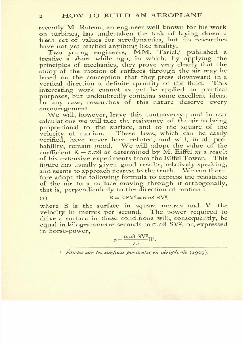
EVERY calculation relatingto aeroplane design is based on
the expression of the resistance offered by the air to a
surface moving through it under given conditions. For
this reason it is impossible to obtain rigorously accurate
numerical results. The basis, the starting-point, of every
calculation, is in fact a subject on which the most eminent
theorists are of divided opinions.
I. Resistance of the air to a plane moving through it
The formula giving the resistance of the air cannot be
stated in invariable terms evento-day,
and it is this fact
which is the cause of so much hesitation on the part of
the constructor in calculating the design of an aeroplane.
The uncertainty of this formula should be ascribed to
the presence of the famous or infamous coefficient K,
which has formed the subjectof so much controversy.
The mysterious figureK assumes the most unexpected
values, nor can the law of its variations be determined.
We cannot say whether this coefficient hides an unknownlaw, or whether it has a separate value for each different
machine. The solution of this problem has been attempted
by many engineers,but hitherto without success. Only
I
8/6/2019 1910 howtobuildaeropl00petirich
http://slidepdf.com/reader/full/1910-howtobuildaeropl00petirich 22/150
2 HOW TO BUILD AN AEROPLANE
recentlyM. Rateau, an engineer well known for his work
on turbines, has undertaken the task of laying down a
fresh set of values for aerodynamics, but his researches
have not yet reached anything like finality.
Two young engineers,MM. Tariel,
1
published a
treatise a short while ago, in which, by applying the
principlesof mechanics, they prove very clearly
that the
study of the motion of surfaces through the air may be
based on the conception that they press downward in a
vertical direction a definite quantity of the fluid. This
interestingwork cannot as
yetbe
appliedto
practical
purposes, but undoubtedly contains some excellent ideas.
In any case, researches of this nature deserve every
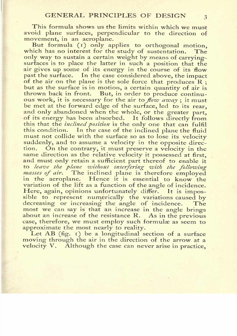
encouragement.We will, however, leave this controversy ;
and in our
calculations we will take the resistance of the air as being
proportional to the surface, and to the square of the
velocityof motion. These laws, which can be easily
verified, have never been refuted, and will, in all pro-
bability,remain good. We will adopt the value of the
coefficient K = 0.08 as determined by M. Eiffel as a result
of his extensive experiments from the Eiffel Tower. This
figurehas usually given good results, relatively speaking,
and seems to approach nearest to the truth. We can there-
fore adopt the following formula to express the resistance
of theair to a surface
moving throughit
orthogonally,that is, perpendicularly
to the direction of motion :
(i)R = KSV2 = o.o8 SV2
,
where S is the surface in square metres and V the
velocityin metres per second. The power required to
drive a surface in these conditions will, consequently, be
equalin kilogrammetre-seconds to 0.08 SV2
, or, expressed
in horse-power,0.08 SV g
75
1 Etudes sur les surfaces portantes en aeroplanie (1 909).
8/6/2019 1910 howtobuildaeropl00petirich
http://slidepdf.com/reader/full/1910-howtobuildaeropl00petirich 23/150
GENERAL PRINCIPLES OF DESIGN 3
This formula shows us the limits within which we must
avoid plane surfaces, perpendicular to the direction of
movement, in an aeroplane.
But formula (i) only applies to orthogonal motion,which has no interest for the study of sustentation. The
only way to sustain a certain weight by means ofcarrying-
surfaces is to place the latter in such a position that the
air gives up some of its energy in the course of its flow
past the surface. In the case considered above, the impactof the air on the plane is the sole force that produces R ;
but as the surface is in
motion,a certain
quantityof air is
thrown back in front. But, in order to produce continu-
ous work, it is necessary for the air to flow away ;it must
be met at the forward edge of the surface, led to its rear,
and only abandoned when the whole, or the greater part,
of its energy has been absorbed. It followsdirectly
from
this that the inclined position is the only one that can fulfil
this condition. In the case of the inclined plane the fluid
must not collide with the surface so as to lose itsvelocity
suddenly, and to assume avelocity in the opposite direc-
tion. On the contrary, it must preserve avelocity in the
same direction as the relative velocity it possessed at first,
and must only retain a sufficient part thereof to enable it
to leave the plane withoutinterfering with the following
masses of air. The inclined plane is therefore employedin the
aeroplane. Henceit is essential to
know thevariation of the lift as a function of the angle of incidence.
Here, again, opinions unfortunately differ. It is impos-sible to represent numerically the variations caused by
decreasing orincreasing the angle of incidence. The
most we can say is that an increase in the angle bringsabout an increase of the resistance R. As in the previous
case, therefore, we must employ such formulae as seem to
approximate the most nearly to reality.
Let AB(fig. i)
be a longitudinal section of a surface
moving through the air in the direction of the arrow at a
velocity V. Although the case can never arise inpractice,

8/6/2019 1910 howtobuildaeropl00petirich
http://slidepdf.com/reader/full/1910-howtobuildaeropl00petirich 24/150
4 HOW TO BUILD AN AEROPLANE
we will consider the air as arriving beneath the surface and
yieldingits energy, due to the relative velocity V, in two
parts : the first, R<2, resisting forward motion, the second,
Rj, producing sustentation. Of these two we need onlyconsider the latter
;for since, in
practice, the main object
aimed at is to decrease the resistance to forward motion,
we may, in theory, consider it to have been attained, and
FIG. i.
assume that the sum-total of the energy of the air is utilised
for sustentation.
In consequence, the results we shall obtain are theoretical
inthe
full
meaningof the
word,since
theywill
finally giveus the power necessary for sustentation alone.
II. Lift of a surface S at a velocityV meeting the air at
an angle of incidence i
By thelift
of an aeroplane surface of area S, meetingthe air at an angle /,
with a velocity V, we denote the
vertical component of the resistance of the air to the sur-
face. In other words, the lift is the weight that can be
lifted by the surface. If we take the velocity as unity,
i.e. i metre per second, and if we give the surface an area
8/6/2019 1910 howtobuildaeropl00petirich
http://slidepdf.com/reader/full/1910-howtobuildaeropl00petirich 25/150
GENERAL PRINCIPLES OF DESIGN 5
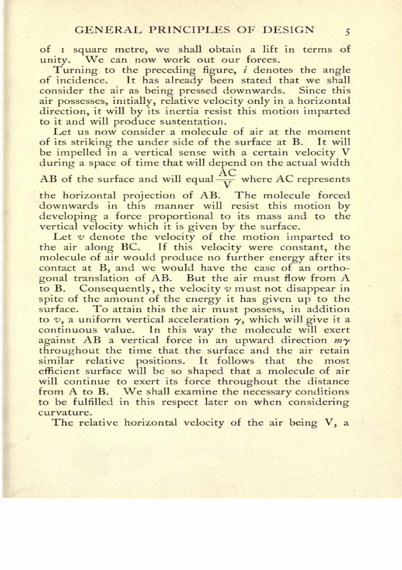
of i square metre, we shall obtain a lift in terms of
unity. We can now work out our forces.
Turning
to the
preceding figure,
/ denotes the angle
of incidence. It has already been stated that we shall
consider the air as being pressed downwards. Since this
air possesses, initially,relative velocity only in a horizontal
direction, it will by its inertia resist this motion impartedto it and will produce sustentation.
Let us now consider a molecule of air at the moment
of its striking the under side of the surface at B. It will
be impelled in a vertical sense with a certain velocity Vduring a space of time that will depend on the actual width
ACAB of the surface and will equal
-== where AC represents
the horizontal projectionof AB. The molecule forced
downwards in this manner will resist this motion by
developing a force proportional to its mass and to the
verticalvelocity
which it is
given bythe surface.
Let v denote the velocity of the motion imparted to
the air along BC. If this velocity were constant, the
molecule of air would produce no further energy after its
contact at B, and we would have the case of an ortho-
gonal translation of AB. But the air must flow from Ato B. Consequently, the velocity v must not disappear in
spite of the amount of the energy it has given up to the
surface. To attain this the air must possess, in addition
to v, a uniform vertical acceleration 7, which will give it a
continuous value. In this way the molecule will exert
against AB a vertical force in an upward direction mythroughout the time that the surface and the air retain
similar relative positions. It follows that the most
efficient surface will be so shaped that a molecule of air
willcontinue to exert
its
force throughout the distancefrom A to B. We shall examine the necessary conditions
to be fulfilled in this respect later on when considering
curvature.
The relative horizontal velocity of the air being V, a
8/6/2019 1910 howtobuildaeropl00petirich
http://slidepdf.com/reader/full/1910-howtobuildaeropl00petirich 26/150
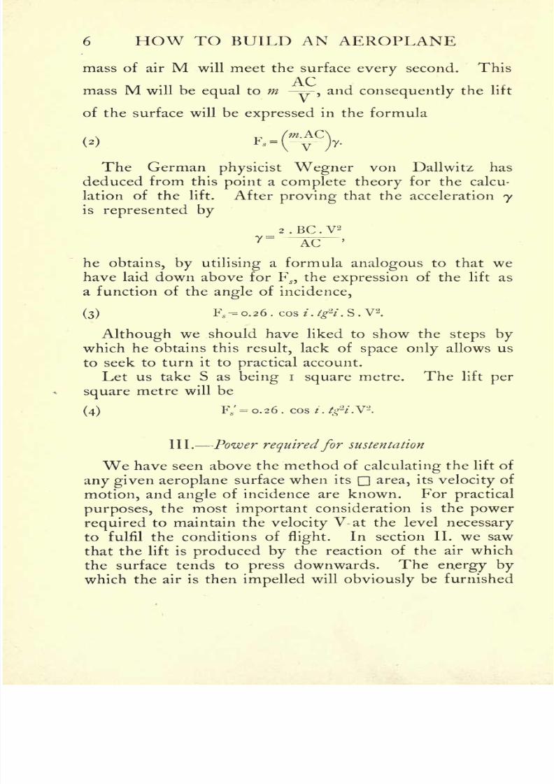
6 HOW TO BUILD AN AEROPLANE
mass of air M will meet the surface every second. This
ACmass M will be equal to m
-^,and consequently the lift
of the surface will be expressed in the formula
m.AC
v
The German physicist Wegner von Dallwitz has
deduced from this point a complete theory for the calcu-
lation of the lift. After proving that the acceleration y
is represented by
_ 2 . BC . V2
7~
^C '
he obtains, by utilisinga formula analogous to that we
have laid down above for FJ}
the expression of the lift as
a function of the angle of incidence,
(3) Fs.-o.26.cos*.#
2
/.S.V
2.
Although we should have liked to show the steps bywhich he obtains this result, lack of space only allows us
to seek to turn it topractical
account.
Let us take S as being i square metre. The lift per
square metre will be
(4) F/ = 0.26 . cos t . tg&i.V2
.
III. Power requiredfor sustentation
We have seen above the method of calculating the lift of
any given aeroplane surface when its n area, its velocity of
motion, and angle of incidence are known. Forpractical
purposes, the most important consideration is the power
requiredto maintain the
velocity
V at the level
necessaryto fulfil the conditions of
flight.In section II. we saw
that the lift is produced by the reaction of the air which
the surface tends to press downwards. The energy bywhich the air is then impelled will obviously be furnished
8/6/2019 1910 howtobuildaeropl00petirich
http://slidepdf.com/reader/full/1910-howtobuildaeropl00petirich 27/150
GENERAL PRINCIPLES OF DESIGN 7
by the motor of the aeroplane. The expression will there-
fore denote the theoretical power required for the given
sustentation, the latter being known a priori from the
weight of the machine and itspilot.
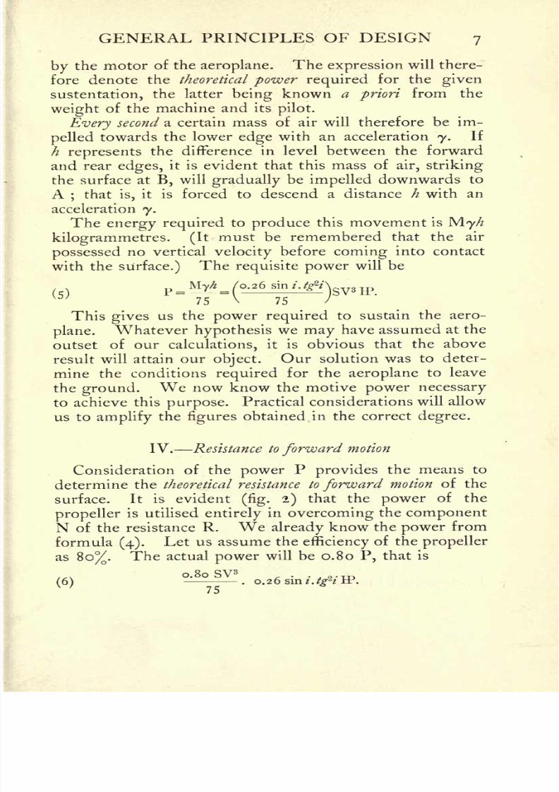
Every second a certain mass of air will therefore be im-
pelled towards the lower edge with an acceleration 7. If
h represents the difference in level between the forward
and rear edges, it is evident that this mass of air, striking
the surface at B, will gradually be impelled downwards to
A;that is,
it is forced to descend a distance h with an
acceleration 7.The energy required to produce this movement is M.yh
kilogrammetres. (Itmust be remembered that the air
possessed no vertical velocity before coming into contact
with the surface.) Therequisite power will be
=..
75 V 75 /
This gives us the power required to sustainthe aero-
plane.Whatever hypothesis we may have assumed at the
outset of our calculations, it is obvious that the above
result will attain ourobject.
Our solution was to deter-
mine the conditions required for the aeroplane to leave
the ground. We now know the motive power necessary
to achieve this purpose. Practical considerations will allow
us to amplify thefigures
obtained in the correct degree.
IV. Resistance to forward motion
Consideration of the power P provides the means to
determine the theoretical resistance to forward motion of the
surface. It is evident(fig. 2) that the power of the
propelleris utilised entirely in overcoming the component
N of the resistance R. Wealready
know the
power
from
formula(4).
Let us assume the efficiencyof the propeller
as 80%. The actual power will be 0.80 P, that is
0.80 SV3, . .
(6)-
. 0.26 sin t.tg*t -tr.

8/6/2019 1910 howtobuildaeropl00petirich
http://slidepdf.com/reader/full/1910-howtobuildaeropl00petirich 28/150
8 HOW TO BUILD AN AEROPLANE
The resistance to forward motion being N, the velocity
of translation of the point O being V, we can write
0.80 P0.80 P =
NV;hence
N
With the help of this formula we shall later be able to
estimate the resistance to forward motion of any aeroplane
FIG. 2.
from the velocity obtained during flight and from the
power developed by its motor.
V.Effect of unit power on the sustaining surface
On the other hand, knowing from formula(3) the lift
of a surface S moving at avelocity
V at an angle of
incidence /, and, on the other hand, knowing the powernecessary for sustentation, we can determine the work
done by i IP by dividing the lift by the power.
(7)F,_o.26 cos /.#
2/SV2
.75__ 75
"F" 0.26 sin / . tg*i SV3
~Vtgi'
VI.Superiority of
theaeroplane
overevery
othertype of
flying machine in respect of lift
In the foregoing calculations we have always considered
the downward impulse imparted to a certain mass of air,

8/6/2019 1910 howtobuildaeropl00petirich
http://slidepdf.com/reader/full/1910-howtobuildaeropl00petirich 29/150
RAL PRINCIPLES OF DESIGN
for which a certain power was required.We have further
seen that the work to be done was greatly inferior to the
force of gravity.Practice confirms the conclusion. To
take an instance : Santos-Dumont's aeroplane, weighing,
including the pilot, 150 kilogrammes (330 Ibs.),rose from
the ground when the screw-propeller gave a pull of 60
kilos (132 Ibs.).
Again, the Wright biplane sustains 500 kilos(i
100Ibs.),
while the thrust of the screw is about 103 kilogrammes,
or 51.5 kilos (113^ Ibs.) by each screw.
But if we turn now to ahelicopter
or
flapping-wingmachine, we see immediately that the propelling organs
must produce first of all a vertical force, neutralising that
of gravity, and this without reckoning the power lost in
consequence of the extreme fluidityof the air. The
aeroplane therefore provides the only economical solution
to the problem of mechanicalflight,
nor can machines of
a different type that may be utilised in future ever deprive
it of this advantage.
VII. Elementary calculations for the design of an aeroplane
fulfillingcertain given conditions
We now possess a knowledge of every element entering
into the calculation of the general features of an aeroplane.
Inpractice, constructional requirements
will enter into
these calculations, but only in so far as the strength of the
materials is affected by the factor of safety and the
modulus of the metals used. An example will demonstrate
moreclearly
than any amount of explanationsthe exact
method of procedure in designing an aeroplane.
The problem may be approached in different ways. It
may be necessary to calculate the sustaining surface from
the given horse-power of a motor which is available and
which one wishes to employ. Or the requirement maybe that a surface of a given area should carry a certain
number of passengers, in which case we should first have
8/6/2019 1910 howtobuildaeropl00petirich
http://slidepdf.com/reader/full/1910-howtobuildaeropl00petirich 30/150
io HOW TO BUILD AN AEROPLANE
to calculate the speed required, and thence deduce the
necessary power. As a general rule, the only conditions
imposed are the weight of the aeroplane and the speed
that can be attained without danger according to thedimensions of the manoeuvring ground. Nowadays the
speed at which an aeroplane should leave the ground is
usually taken as between 60 and 90 km. per hour;that is,
between 16 and 25 metres per second. The starting
grounds utilised, such asIssy, Chalons, Buc, Juvisy, etc.,
render higher speeds dangerous.1
Before we can increase
the
figures givenabove, we should be able to foresee with
absolute accuracy at which precise spot the aeroplane
would leave the ground, which is not yet the case.
The piloting of an aeroplane is subject to so much
uncertainty that the minimum velocity forecasted is some-
times attained only after considerable delay ;and it is
evident that in these circumstances a relatively restricted
starting ground would give rise to serious dangers.
The weight of the aeroplane is one of the factors knownby the builder a priori. He starts, in fact, with the
knowledge of the number of passengers he wishes to carry,
of the approximate weight of motor, framework, etc.
Having made these preliminary remarks, we can now
set ourselves the following problem, which will serve as
an example of the method of applying the formula given
above :
An aeroplane designed to carry two people weighs in
all 500 kilos (iioo Ibs.).The
starting ground limits the
speed to 60 km. p.h. What are the characteristic features
of the aeroplane ?
Our solution will be divided into several parts.
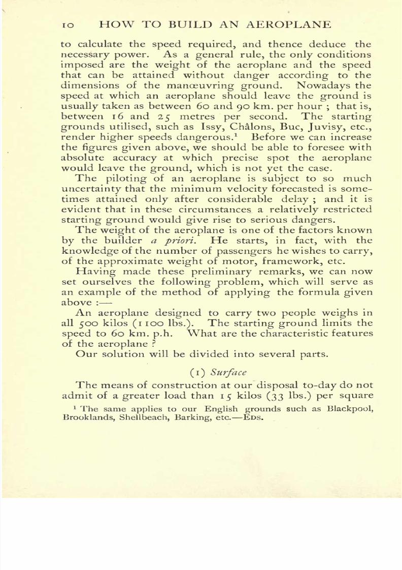
(i) Surface
The means of construction at our disposal to-day do not
admit of a greater load than 15 kilos (33 Ibs.) per square
1 The same applies to our English grounds such as Blackpool,
Brooklands, Shellbeach, Barking, etc. EDS.
8/6/2019 1910 howtobuildaeropl00petirich
http://slidepdf.com/reader/full/1910-howtobuildaeropl00petirich 31/150
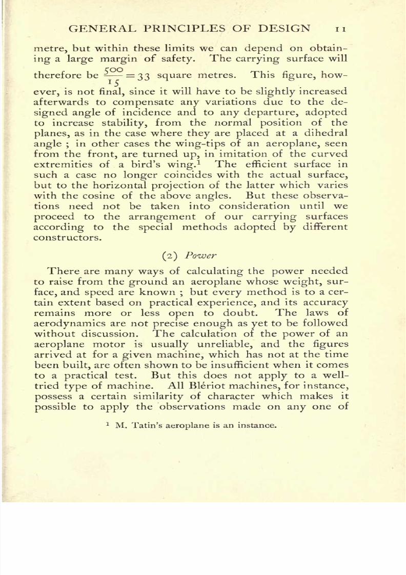
GENERAL PRINCIPLES OF DESIGN n
metre, but within these limits we can depend on obtain-
ing a large margin of safety.The carrying surface will
therefore be-
=33 square metres. This figure, how-
ever, is not final, since it will have to beslightly
increased
afterwards to compensate any variations due to the de-
signed angle of incidence and to any departure, adoptedto increase
stability,from the normal position of the
planes, as in the case where they are placed at a dihedral
angle ;in other cases the wing-tips of an aeroplane, seen
from the front, are turned up, in imitation of the curvedextremities of a bird's wing.
1 The efficient surface in
such a case no longer coincides with the actual surface,
but to the horizontal projection of the latter which varies
with the cosine of the above angles. But these observa-
tions need not be taken into consideration until we
proceed to the arrangement of our carrying surfaces
according
to thespecial
methodsadopted by
different
constructors.
(2) Power
There are many ways of calculating the power needed
to raise from the ground an aeroplane whose weight, sur-
face, and speed are known;but every method is to a cer-
tain extent based on practical experience, and its accuracy
remains more or less open to doubt. The laws of
aerodynamics are not precise enough as yet to be followed
without discussion. The calculation of the power of an
aeroplane motor is usually unreliable, and the figures
arrived at for a given machine, which has not at the time
been built, are often shown to be insufficient when it comes
to a practical test. But this does not apply to a well-
tried type of machine. All Bleriot machines, for instance,
possess a certain similarityof character which makes it
possible to apply the observations made on any one of
1 M. Tatin's aeroplane is an instance.
8/6/2019 1910 howtobuildaeropl00petirich
http://slidepdf.com/reader/full/1910-howtobuildaeropl00petirich 32/150
12 HOW TO BUILD AN AEROPLANE
them to every one of the remaining machines of the type.
Unfortunately the limits of this work do not allow us to
explain some of the theoretical methods employed.
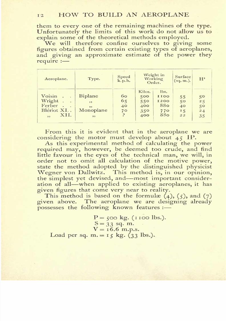
We will therefore confine ourselves to giving some
figuresobtained from certain existing types of aeroplanes,
and giving an approximate estimate of the power they
require:
From this it is evident that in the aeroplane we are
considering the motor must develop about 45 IP.
As this experimental method of calculating the power
required may, however, be deemed too crude, and find
little favour in the eyes of the technical man, we will, in
order not to omit all calculation of the motive power,
state the method adopted by the distinguished physicist
Wegner von Dallwitz. This method is, in our opinion,the simplest yet devised, and most important consider-
ation of all when applied toexisting aeroplanes, it has
given figuresthat come very near to
reality.
This method is based on the formulae(4), (5),
and (7)
given above. The aeroplane we are designing already
possesses the following known features :
P = 500 kg. (i 100 Ibs.).
S-33 sq.m.
V = 1 6. 6 m.p.s.
Load per sq.m. = 15 kg. (33 Ibs.).

8/6/2019 1910 howtobuildaeropl00petirich
http://slidepdf.com/reader/full/1910-howtobuildaeropl00petirich 33/150
GENERAL PRINCIPLES OF DESIGN 13
We now proceed as follows :
In the formula giving the lift, we make S = i and V = i.
There remains :
F/ ==0.26 cos i.tg^i.
If now we work out every value of F/ for every value
of / from i to 70, we shall know what angle of incidence
must be adopted for a surface of isq.
m. moving at a
velocityof i m.p.s. to lift our chosen weight of 15 kg.
But in order that the machine may leave the ground we
must have
|=V*F.'; or 15
=(16.6)2 F.' ;
hence F/ = 0.054545.
From the table of values we have just previously
calculated, we find that 26 is the value of/, corresponding
to 0.054545.
According to formula(7)
P=V/.
* 75
A knowledge of F/ will give us the value of F^. But,
as a rule, according to Wegner von Dallwitz himself, it is
more convenient in regard to F?and to the corresponding
angles / to calculate the value of
F'
P' = tei IP*
75
obtained by making V = i and F/ = Fs
in the formula
which gives P. We thus get to know the power needed
per unit of speed. The total power P is consequently
obtained by multiplying P' by SV3. In our case P' =
0.000317, hence
P = SV8P' IP,
whence
P-33(i6.6)3
o.ooo3i7P = 47lP.
The power required to raise our aeroplane from the
ground therefore works out at 47 IP. A 50 HP motor
8/6/2019 1910 howtobuildaeropl00petirich
http://slidepdf.com/reader/full/1910-howtobuildaeropl00petirich 34/150
1 4 HOW TO BUILD AN AEROPLANE
will amply suffice, since the method of calculation followed
allows for the simultaneous variation of the angle of in-
cidence and the speed withoutaffecting the result. In
practice, as is almost invariably the case, the angle of in-cidence will probably be smaller and the speed greater.
To sum up, the chief features of our machine are :
Weight .... 500 kg. (i100
Ibs.).
Carrying surfaces . . . 33 sq.m.
Motor . . . 50 IP.
Probable speed ... 70 k.p.h.
Loadper sq.
m. . . .
15 kg. (33 Ibs.).
VIII. Application of the motive-power Calculation
of the propeller
To turn to practical use the power of our 50 IP motor,the power developed must be transformed into a tractive
effort acting on the surfaces, compelling the latter to
move forwards, this forward motion resulting in susten-tation. These transformers will have to find their pointof support on the air, a fluid and unstable medium.
The only device employed in aeronautics to fulfil this
purpose is the screw-propeller, which consists of surfaces
arranged in a special manner about an axis to which theyare fixed
;the rotation of the axis causes the surfaces to
rotate likewise and to drive back the air to the rear, thus
tending to move forwards. This tendency to advance is
utilised to drive the aeroplane. It follows that the designof an efficient propeller is a matter of extreme
delicacy.
The whole question ofpropellers is very little under-
stood at the present day, and it is difficult to find a complete
theory for their calculation. Many theorists have ex-
amined the question, but among them only very few
indeed have evolved a comprehensive and connected
theory. Among the remainder there are some Sir
Hiram Maxim and William Froude, for instance whohave emitted correct views and made valuable observa-

8/6/2019 1910 howtobuildaeropl00petirich
http://slidepdf.com/reader/full/1910-howtobuildaeropl00petirich 35/150
GENERAL PRINCIPLES OF DESIGN 15
tions, but without explaining them with sufficient
clearness.
Practical experiment still remains master of the situa-
tion, and the majority of constructors follow their ownspecial
method of design. But, as a rule, their chief
error lies infixing
a priori the diameter of the propeller.
Nothing could well be moreillogical.
The diameter,
the principal dimension of the propeller, is the very first
that ought to vary according to the power. Their next
mistake, usually, is to base the other dimensions of the
propeller
on that of its diameter. Onebuilder,
for
instance,favours a pitch
= iJ diameters, the width of the blades
being made =\ diameter. These methods, to say the
least, lack the mathematical accuracy that ought to be the
first consideration in propeller-design ;and low
efficiency
can usually be ascribed to these causes.
The most complete theory of the screw-propeller in
existence is the one published last year by the Russian
engineer, M. Drzewiecki, whose remarkable works onfluids are widely known. 1
Drzewiecki's theory is worth following, principallyon
account of the strict reasoning on which it is founded.
Moreover, even if it should prove not to beabsolutely
accurate, it has the further advantage ofresulting in a
method of construction which can be immediately applied
inpractice. (Further
reference to this
pointwill be
madein the chapter on the Construction of
Propellers.) Con-
sequently, in his case, errors, which cannot be eliminated
from any theory, are, at any rate, not increased by faults
in the construction. We will, therefore, in the next para-
graph follow Drzewiecki's method ofcalculating the design
of a propeller driven by a 50 IP motor, revolving at
600 r.p.m., or 10r.p.s.
Number of blades On this point Drzewiecki's theory is
notexplicit enough. In consequence, we will adopt the
usual number of blades, two, without going into the
1Drzewiecki, Des helices aeriennes, 1 909.

8/6/2019 1910 howtobuildaeropl00petirich
http://slidepdf.com/reader/full/1910-howtobuildaeropl00petirich 36/150
1 6 HOW TO BUILD AN AEROPLANE
theoreticalquestion. At the same time, we may point
out that three blades might be preferable.
Diameter of propeller To arrive at the diameter we
must first calculate the modulus*
of the propeller :
V 16M=-~
;that is M = = 0.26.
27T/Z 27TIO
The diameter D is given by
D = M x ic = 2.60 metres.
Inreality,
the width of the blade is constant;
this is
what M. Drzewiecki implies by the term specific width of
the blade.
It is constant, and, as can be shown mathematically,
equal to fths of the modulus :
W =o.75 M = o. 75 x 0.26 = 0.195 metres.
From the working drawings given in M. Drzewiecki's
book we can now construct the templatesfor the
surfaceof the blades. But this will be dealt with in the chapter
on Construction.
The propellerof our aeroplane will, therefore, have
the following dimensions : Diameter 2.60 m.; specific
width 0.195 m.; r.p.s.
10.
The blades ought not, as is sometimes thought, to
start from the boss, but at a certain distance fromit,
equalto half the modulus M, or in this case = 0.13
metres. We know that any point on the propeller
diameter revolves at a speed inversely proportional to its
distance from the centre. Thetips
of the blades move
at a velocitymrY) (n being the number of rev.
p.sec. and
D the diameter). Consequently, as we approach nearer to
the centre the speed will diminish in the proportion
given, and the angle of incidence of the blades must beincreased to produce the same amount of work. But the
1 Modulus is the term used by M. Drzewiecki to denote the pitch-
constant.

8/6/2019 1910 howtobuildaeropl00petirich
http://slidepdf.com/reader/full/1910-howtobuildaeropl00petirich 37/150
GENERAL PRINCIPLES OF DESIGN 17
effect of this increased angle of incidence disappears after
it has reached a certain point.
In a communication to the Academy of Sciences in
Paris, the late Captain Ferber laid down the followingaxiom which bears on the point, but is only of importancein actual practice :
Rojct
JL.
FIG. 3.
" Whether a plane moves through the air in an inclined
position or almost at a tangent to its trajectory,the resist-
ance of the air to the gravitating tendency of the total
weight remains almost the same."
We therefore reach a point at which it is preferable to
cut away the blade, a fact which, as we have seen, is in
accord both with theory and withpractice. Fig. 3 gives
a diagrammatic view of the propellerand its dimensions.
8/6/2019 1910 howtobuildaeropl00petirich
http://slidepdf.com/reader/full/1910-howtobuildaeropl00petirich 38/150
1 8 HOW TO BUILD AN AEROPLANE
Having explained the method of calculating the
principal dimensions of the aeroplane and propeller
every one of these calculations being based on theoretical
principles we can now turn to their practical application.
For, as we shall see, it is not sufficient to give the carry-
ing surfaces a certain area;
their shape is a matter of
equal importance. The efficiencyof the carrying surfaces,
in fact, varies greatly with their shape, and, above all,
with the form of the perimeter.
IX. Arrangement of the surfaces
One fact has been noticed during the course of every
experiment dealing with resistance of the air to the passage
through it of a plane surface, i.e. that if the resistance Ris proportional to the area of the planes it varies with
their perimeter. It has always been a point ofcapital
importance for the development of the aeroplane to
determine the causes of these variations.
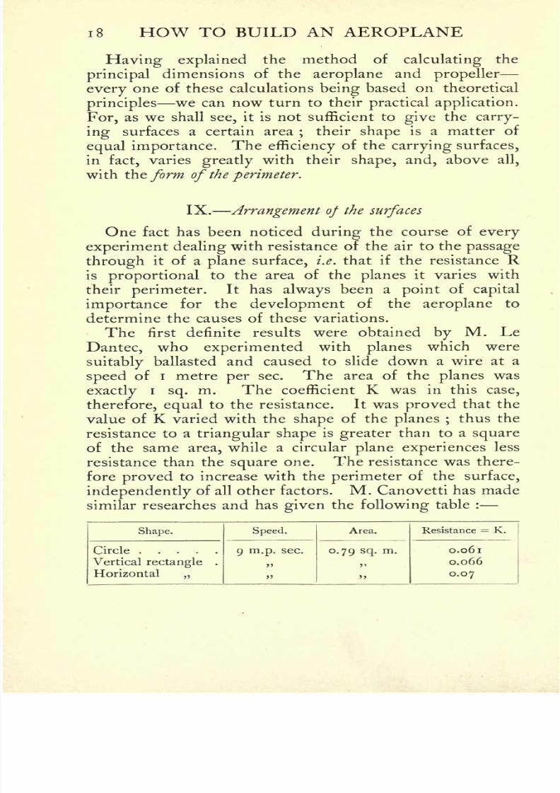
The first definite results were obtained by M. Le
Dantec, who experimented with planes which were
suitablyballasted and caused to slide down a wire at a
speed of i metre per sec. The area of the planes was
exactlyi
sq.m. The coefficient K was in this case,
therefore, equal to the resistance. It was proved that the
value of K varied with the shape of the planes ;thus the
resistance to a triangular shape is greater than to a square
of the same area, while a circular plane experiences less
resistance than the square one. The resistance was there-
fore proved to increase with the perimeter of the surface,
independently of all other factors. M. Canovetti has made
similar researches and has given the following table :

8/6/2019 1910 howtobuildaeropl00petirich
http://slidepdf.com/reader/full/1910-howtobuildaeropl00petirich 39/150
GENERAL PRINCIPLES OF DESIGN 19
This table already shows the influence of the position
of the greater side of a rectangle relatively to the direction
of motion.
M. Eiffel has obtained the following values :
The dimensions of the rectangle a were 4/1,those of
rectangle b were2/1.
These figures indicate the effect
of the outline of the plane when moving orthogonally,
which, however, is of no direct interest. But they are
important in that they show that in an aeroplane all use-
less surfaces(i.e.
that do not produce lift)situated per-
pendicularly to the direction of motion ought to be givena circular shape.
For the inclined plane the only conclusion that can be
made from these experiments is that arectangle meeting
the air with its
largerside
experiencesfar
greaterresist-
ance than a rectangle meeting the air with its lesser side.
Among the formulae which bear on this point we need
only mention that of M. Soreau, who takes into account the
factors of the length and width of the rectangle.
In almost every formula hitherto enunciated are
included values of a more or less fantastic nature, which
rob them of practical value. We must therefore be
guided almost entirely by experimental data, such as the
observation of the outstretched wing of a bird, on which
to model the shape of our surfaces. The works of
Mouillard, Pettigrew, Marey, and Lilienthal are the best
8/6/2019 1910 howtobuildaeropl00petirich
http://slidepdf.com/reader/full/1910-howtobuildaeropl00petirich 40/150
20 HOW TO BUILD AN AEROPLANE
to consult on this point ;and of these, Lilienthal is to be
preferred to the others by reason of the accurate measure-
ments hegives, and to which he always attached the
greatest importance. We will therefore turn to his
book 1 for a model on which to base the shape of the
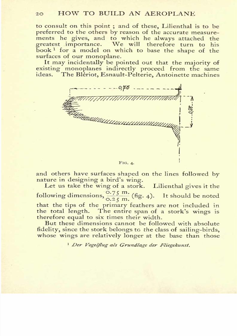
surfaces of our monoplane.It may incidentally be pointed out that the majority of
existing monoplanes indirectly proceed from the same
ideas. The Bleriot, Esnault-Pelterie, Antoinette machines
FIG. 4.
and others have surfaces shaped on the lines followed by
nature in designing a bird's wing.Let us take the wing of a stork. Lilienthal gives it the
following dimensions, (fig. 4). It should be noted
that thetips
of the primary feathers are not included in
the total length. The entire span of a stork's wings is
thereforeequal
to six times their width.
But these dimensions cannot be followed with absolute
fidelity,since the stork belongs to the class of
sailing-birds,
whose wings arerelatively longer at the base than those
1 Der Vogelflug als Grundlage der Fliegekunst.

8/6/2019 1910 howtobuildaeropl00petirich
http://slidepdf.com/reader/full/1910-howtobuildaeropl00petirich 41/150
GENERAL PRINCIPLES OF DESIGN 21
of thesoaring-birds, as is shown perfectly clearly
in
Mouillard's Empire de PAir. In the wings of an
aeroplane, therefore, the maximum width ought not to
be less than ^th of the total span. This proportion is
the one adopted by M. Tatin in his aeroplane, which has
a ratio of 5 to i.
It must, however, be acknowledged that in arriving
at these dimensions constructional requirements have
FIG. 5.
been taken into consideration;
for an aeroplane must
not be given too large a span, since this would necessi-
tate the construction of immensely broad sheds, and
would seriously affect thesolidity
of construction of the
machine. In preserving the area of the surfaces it
becomes in
consequencenecessary to increase the width
relatively. ( ,
In accordance with the above remarks, we now proceedto arrange the carrying surface of our projected aeroplane
according tofig. 5.
The span of 13 metres will not appear
8/6/2019 1910 howtobuildaeropl00petirich
http://slidepdf.com/reader/full/1910-howtobuildaeropl00petirich 42/150
22 HOW TO BUILD AN AEROPLANE
too great if it is remembered that the aeroplane is to lift
500 to 570 kilos,(i
100 to 1250 Ibs.).
The Wright machine, which lifted a similar weight, has
approximately the same dimensions for each of its planes.
The length, fore and aft, of the machine will be roughly
equal to the span. Here, again, we are guided by nature
and by existing machines. It is clear that wherestability
is obtained by means of atail, the greater the distance of
the latter from the carrying surface, thegreater will be its
effect on the longitudinal balance, on account of itsleverage.
But since an increase in this distance entails difficulties ofconstruction and makes the machine unwieldy, the lengthis not allowed to exceed the dimension of the span. This
arrangement has the further advantage that the tail plane
acts in the same part of the air as the machine itself, so
that the danger of currents of different directions acting
on different parts of the machine is decreased.
X. Lateral stability Position of the centre ofgravity
Before adopting any specificmeans for ensuring the
lateral stabilityof an aeroplane, the-latter must be considered
in every positionit may be caused to assume during flight,
and in each case the sum-total of the forcesacting upon
it must be taken into account. In this way the aeroplane
is considered first during normal flight, i.e. when its tra-
jectorylies in a straight line, and later in any departures
from the normal, such as when turning. Before adoptinga particular
method of preserving thestability
of an aero-
plane during itsflight
in astraight line, it will therefore
be necessary to see whether the method is efficient when
the forces acting during a turn are taken into consideration.
Before we proceed to examine the effect of the centre of
gravity,it is necessary to state that we need only consider
the resultant of the forces and its effect, and that no
attention must be paid to the misleading effect of the
individual components.

8/6/2019 1910 howtobuildaeropl00petirich
http://slidepdf.com/reader/full/1910-howtobuildaeropl00petirich 43/150
GENERAL PRINCIPLES OF DESIGN 23
(a) Flight in a horizontal straightline In this case the
aeroplane is only subjectedto two forces weight and lift.
Under their combined action the aeroplane is in equi-
librium in calm air. The only feature inherent in the
design, which will avoid the upsetting of the aeroplane if
it is struck by a current of air, is to placethe centre of
gravity below the centre of resistance. This is an essential
FIG. 6.
condition of lateral stabilityin an aeroplane. When the
weight is thus disposed, as soon as the aeroplane tilts to
one side, the component GjP, through its lever arm OG,tends to restore the aeroplane to a position of equilibrium.
This lever arm is in any case constant, but since GjPincreases with the tilt, the action of the weight will increase
in like degree, with excellent results. This application of
the centre of gravity is shown in elementary physics bythe pendulum. In proportion as the centre of gravity is
situated closer to O, the "sensitiveness" of the pendulum

8/6/2019 1910 howtobuildaeropl00petirich
http://slidepdf.com/reader/full/1910-howtobuildaeropl00petirich 44/150
24 HOW TO BUILD AN AEROPLANE
increases;
thatis, its tendency to restore equilibrium
grows less.
A dihedral angle of the planes (i.e. each wing being
turned upwards laterally) brings about great stability, butthis method also is only effective when the centre of
gravity is low. Since it has the disadvantages of entailingan increase in the
sustaining surface and of behaving very
badly in side-winds, it is preferable to employ wings with
FIG. 7.
a continuous forward
edge
mounted above the
plane
con-
taining the motor. The monoplane Bleriot XII.(fig. 7) is
excellently designed in this respect, and has proved the
correctness of this system of construction inpractice.
(b) Turning Some few constructors, such as Esnault-
Pelterie in France and Grade in Germany, have, on the
contrary, placed their centre of gravity above the centre
of resistance, with the object of rendering turning move-
ments more easy to execute. Let us see what will
happen during the turning movement of an aeroplane
with the centre of gravity situated at different points.
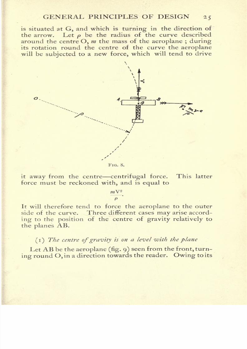
Let us take an aeroplane (fig. 8) whose centre of gravity
8/6/2019 1910 howtobuildaeropl00petirich
http://slidepdf.com/reader/full/1910-howtobuildaeropl00petirich 45/150
GENERAL PRINCIPLES OF DESIGN 25
is situated at G, and which is turning in the direction of
the arrow. Let p be the radius of the curve described
around the centre O, m the mass of the aeroplane ; during
its rotation round the centre of the curve the aeroplane
will be subjected to a new force, which will tend to drive
o.
FIG. 8.
it away from the centre centrifugal force. This latter
force must be reckoned with, and is equal to
It will therefore tend to force the aeroplane to the outer
side of the curve. Three different cases may arise accord-
ing to the position of the centre of gravity relatively to
the planes AB.
(i)The centre ofgravity is on a level with the plane
Let AB be the aeroplane (fig. 9) seen from the front, turn-
ing round O, in a direction towards the reader. Owing to its

8/6/2019 1910 howtobuildaeropl00petirich
http://slidepdf.com/reader/full/1910-howtobuildaeropl00petirich 46/150
26 HOW TO BUILD AN AEROPLANE
rotation round O, the aeroplane will be forced towards the
mV'2
outside by reason of the force -
applied to the centre
P
of gravity G. It is manifest that if the plane AB remains
/
FIG. 9.
horizontal, the aeroplane will be diverted from its course,
mV2
since only the side B will oppose the force - -. In order
to neutralise this force it becomesnecessary to resort to
FIG. 10.
another method, which consists intilting
the aeroplane
laterally, as in fig. 10, so as to create an antagonistic force.
Since the resistance R remains perpendicular to AB, it
will be tilted with the plane. It can then be resolved
into two forces, GM and GN, the former vertical, the
8/6/2019 1910 howtobuildaeropl00petirich
http://slidepdf.com/reader/full/1910-howtobuildaeropl00petirich 47/150
GENERAL PRINCIPLES OF DESIGN 27
latter horizontal. The anglea will be regulated either
automatically or by the pilotuntil GN = GF.
This action may be obtained by many different methods,
every one of which, however, really amounts to a warpingof the surfaces. The "
aileron" 1
<% being lowered, the
air is confined in a pocket and tends to raise GB around
the axis G, whilst the aileron #2
* s raised. A tends to
descend.
It will be noticed that in this first case, in which the
centre of gravity is situated on a level with the planes,
the weight has no effect on the evolution,since it
onlyacts as the centre of rotation. The force GN, which is
equal and directly opposed to centrifugal force, will simply
neutralise the latter without exerting any other effect on
the aeroplane, for the simple reason that in this case there
exists no lever arm allowing the forces that are called into
play to upset transverse equilibrium.
The tilting of the aeroplane, and consequently that of
the air-resistance, has the inevitable result of decreasing
thelift, which before the turning movement began was
equal to R, but during the turn is only equal to R cos a.
The aeroplane, therefore, will descend during the turn.
And this actually occurs, so that the pilot must, before
tiltinghis aeroplane for the turn, ascertain that his height
above the ground is sufficient to allow him to clear any
obstacles during turning.The decrease in the lift brings about a difference
between the resultant of the forces acting on the planes
and of those acting on the centre of gravity.
The latter isslightly stronger than the former, and the
force E forms with the force R an angle <^>,which is very
small, but nevertheless appreciable.The result is a
component which, in case the aeroplane is tilted too far,
will cause it to drift to the inner side of the curve. But
if,on the other hand, the aeroplane is not tilted at a
sufficientangle, the force resulting
from GN and F will
1 Movable wing-tip or auxiliary plane.
8/6/2019 1910 howtobuildaeropl00petirich
http://slidepdf.com/reader/full/1910-howtobuildaeropl00petirich 48/150
28 HOW TO BUILD AN AEROPLANE
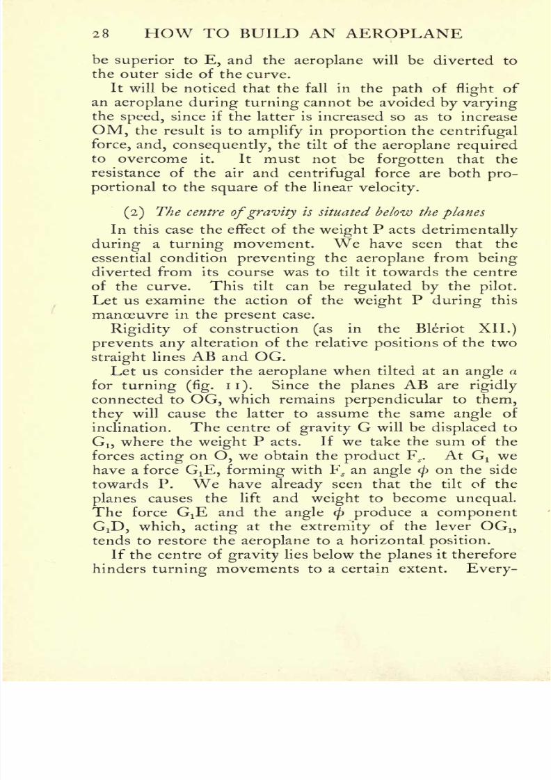
be superior to E, and the aeroplane will be diverted to
the outer side of the curve.
It will be noticed that the fall in the path offlight
of
an aeroplane during turning cannot be avoided by varyingthe speed, since if the latter is increased so as to increase
OM, the result is to amplify in proportion thecentrifugal
force, and, consequently, the tilt of the aeroplane requiredto overcome it. It must not be forgotten that the
resistance of the air and centrifugal force are both pro-
portional to the square of the linearvelocity.
(2) The centre ofgravity is situated below the planes
In this case the effect of the weight P acts detrimentally
during a turning movement. We have seen that the
essential condition preventing the aeroplane from being
diverted from its course was to tilt it towards the centre
of the curve. This tilt can be regulated by thepilot.
Let us examine the action of the weight P during this
manoeuvre in the present case.
Rigidity of construction(as
in the Bleriot XII.)
prevents any alteration of the relative positions of the two
straightlines AB and OG.
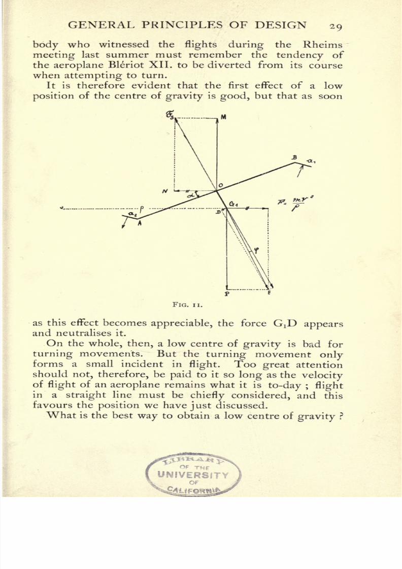
Let us consider the aeroplane when tilted at an anglea
for turning (fig. 11). Since the planes AB arerigidly
connected to OG, which remains perpendicular to them,
they
will cause the latter to assume the sameangle
of
inclination. The centre of gravity G will be displaced to
Gj, where the weight P acts. If we take the sum of the
forces acting on O, we obtain the product F^. At Gtwe
have a force GiE, forming with F^ an angle <pon the side
towards P. We have already seen that the tilt of the
planes causes the lift and weight to become unequal.
The force G:E and the angle <p produce a component
GiD, which, acting at the extremity of the lever OG1?
tends to restore the aeroplane to a horizontal position.
If the centre of gravitylies below the planes it therefore
hinders turning movements to a certain extent. Every-
8/6/2019 1910 howtobuildaeropl00petirich
http://slidepdf.com/reader/full/1910-howtobuildaeropl00petirich 49/150
GENERAL PRINCIPLES OF DESIGN 29
body who witnessed theflights during the Rheims
meeting last summer must remember the tendency of
the aeroplane Bleriot XII. to be diverted from its course
when attempting to turn.
It is therefore evident that the first effect of a low
position of the centre of gravity is good, but that as soon
FIG. ii.
as this effect becomes appreciable, the force GjD appearsand neutralises it.
On the whole, then, a low centre of gravity is bad for
turning movements. But the turning movement onlyforms a small incident in
flight.Too great attention
should not, therefore, be paid to it so long as thevelocity
of flight of an aeroplane remains what it is to-day ; flight
in astraight line must be
chiefly considered, and this
favours the position we have just discussed.
What is the best way to obtain a low centre ofgravity ?
OF THF
UNIVERSITYOF
8/6/2019 1910 howtobuildaeropl00petirich
http://slidepdf.com/reader/full/1910-howtobuildaeropl00petirich 50/150
30 HOW TO BUILD AN AEROPLANE
The oldest method was to arrange the planes so that theyformed an obtuse or dihedral
angle. Unfortunately this
method is bad, for the reason that it renders the aeroplane
more likely to capsize in a side-wind. In our opinion it
is greatly preferable to build the planes as one continuous
surface above the frame containing motor, tanks, and pilot,
after the method adopted by Bleriot in his monoplaneNo. XII., which caught fire and was destroyed at Rheims
on August 29, 1909.
(3) Centre ofgravity above the planes
This is the position adopted by Esnault-Pelterie in
France for his monoplanes, and in the German biplanes
of Grade.
Referring tofig. 12, it will be seen that, for the same
reasons stated in the preceding section, the inequality
between the lift during a turning movement and the
weight P tends to accentuate the inward tilt of the aero-
plane, thus preventing its diversion from its course.This position of the centre of gravity is therefore ex-
cellent for a turning movement, which by its aid can be
accomplished at a very high rate of speed, but for main-
taining stability during straight flightit is most deficient :
any departure from equilibrium is immediately increased
by the high position of the centre ofgravity, and it is
exceedingly difficult to check this tendency to upset.
The dangers of the system have beenpractically illustrated
by the accidents that have occurred to the Esnault-Pelterie
monoplane at Buc.1
On the whole, the problem of thestability
of an
aeroplane may be said to be in complete accord with the
laws of the pendulum. The three cases we have considered
follow the lawsexactly.
From this we may conclude that
the best method for ensuring stability is, at any rate at
the present day, to place the centre of gravity below the
planes.1 On more than one occasion the machine turned turtle. EDS.

8/6/2019 1910 howtobuildaeropl00petirich
http://slidepdf.com/reader/full/1910-howtobuildaeropl00petirich 51/150
GENERAL PRINCIPLES OF DESIGN 31
As soon as the speed of the aeroplane reaches a
sufficiently high figure, stability during straight flight
will no longer need to be considered.
Then we shall only have to concern ourselves with
stability during turning movements;and not till then
will the principle adopted by Esnault-Pelterie prove
practicable. For its high speed will render the aeroplane
indifferent to any atmospheric currents, thus ensuring
stability during straight flight ;and the centre of gravity,
then situated above the planes, will allow it to execute
the sharpest turn insafety.
But at the present time, when the speed offlight
is
relatively slow, we dare not adopt this system, but must
rather concern ourselves mainly with thestability
of the
aeroplane during itsflight
in astraight
line. The centre
of gravity, therefore, must be placed below theplanes.
The future will see its position altered to above the
planes, thus vindicating M. Esnault-Pelterie's contention.
XI. Longitudinal stability
The longitudinal stabilityof an aeroplane offers few
difficulties. It is automatic, provided always that the
8/6/2019 1910 howtobuildaeropl00petirich
http://slidepdf.com/reader/full/1910-howtobuildaeropl00petirich 52/150
32 HOW TO BUILD AN AEROPLANE

8/6/2019 1910 howtobuildaeropl00petirich
http://slidepdf.com/reader/full/1910-howtobuildaeropl00petirich 53/150
GENERAL PRINCIPLES OF DESIGN 33
surface of the elevator besufficiently great. Two distinct
systems of obtaining stability may be employed : in the
first, the horizontal rudder is placed in the rear;in the
second, it is in front of the carrying planes.
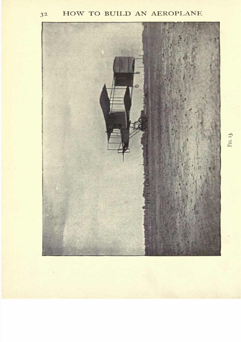
To the former type belong the Voisin machines, to the
latter the Wright aeroplane. The majority of machines
to-day, as a matter of fact,
belong to the former type.
The second is mainlyfavoured by the Ameri-
can school theWrights,
Herring, Curtiss, etc.(figs.
13 and 14).
We will now consider
the action of the horizontal
rudder in these machines
during ascent and descent.
Let us take the aero-
plane with a carrying plane
AB(fig.
15) moving in the
direction of the arrow at a
velocity V. The air exerts
a vertical resistance F^ ap-
plied to the point M. Let
us assume that the centre
ofgravity
lies atthe pointG on the vertical line A.
The weight P of the aero-
plane, equal but opposite to the lift, acts on this point.
A couple will therefore arise tending to turn the whole
of the plane AB around a horizontal axis passing throughthe point K at the centre of the line joining the points
where the two forces areapplied. The surface AB will
assume the position A'B', and this must be avoided. In
order to counteract this couple, a surface CD is placedin the rear of AB. The surface CD receives from the air a
vertical force F which counteracts the effect of the couple
3
FIG. 14.
8/6/2019 1910 howtobuildaeropl00petirich
http://slidepdf.com/reader/full/1910-howtobuildaeropl00petirich 54/150
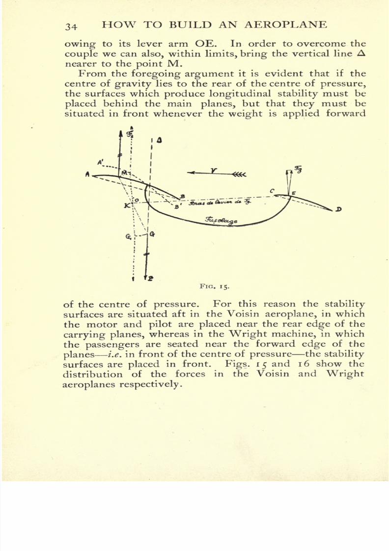
34 HOW TO BUILD AN AEROPLANE
owing to its lever arm OE. In order to overcome the
couple we can also, within limits, bring the vertical line Anearer to the point M.
From the foregoing argument it is evident that if the
centre of gravity lies to the rear of the centre of pressure,
the surfaces which produce longitudinal stabilitymust be
placed behind the main planes, but that they must be
situated in front whenever the weight is applied forward
FIG. 15.
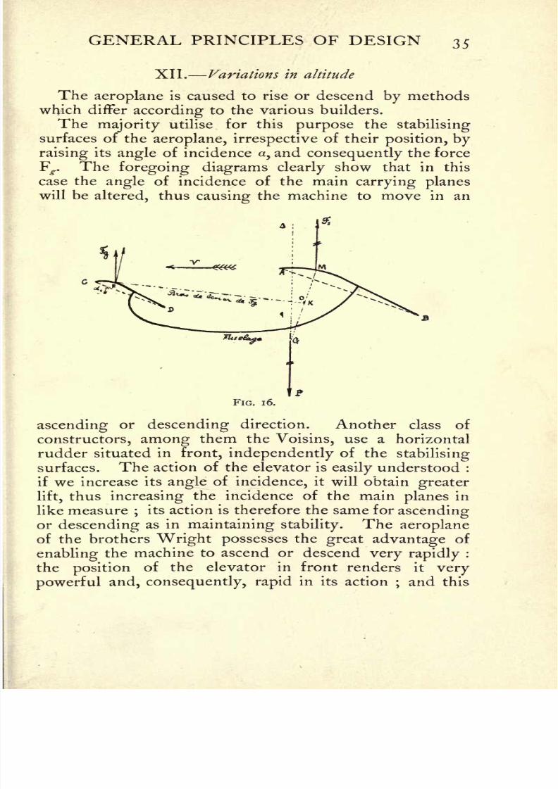
of the centre of pressure.For this reason the
stability
surfaces are situated aft in the Voisin aeroplane, in which
the motor and pilotare placed near the rear edge of the
carrying planes, whereas in the Wright machine, in which
the passengersare seated near the forward edge of the
planesi.e. in front of the centre of pressure the
stability
surfaces are placed in front. Figs. 1 5and 1 6 show the
distribution of the forces in the Voisin and Wright
aeroplanes respectively.
8/6/2019 1910 howtobuildaeropl00petirich
http://slidepdf.com/reader/full/1910-howtobuildaeropl00petirich 55/150

8/6/2019 1910 howtobuildaeropl00petirich
http://slidepdf.com/reader/full/1910-howtobuildaeropl00petirich 56/150
36 HOW TO BUILD AN AEROPLANE
unquestionably forms one of the best features of this
machine. Among those who have adopted the same
system are Bleriot, Esnault-Pelterie, Tatin, Santos-
Dumont, Antoinette, Pischoff-Koechlin, etc. The num-ber of builders who have adopted a joint
elevator and
stabilisingsurface is small, and includes Voisin, Bonnet-
Labranche, and Farman.
XIII. Direction
It would be unnecessary to devote an entire sectionto
the question of direction, since it possesses little special
interest. The solution simply consists inutilising
verti-
cal planes turning round a vertical axis.
This concludes our study of the first principlesand the
general technique of aeroplane construction. Perhaps the
briefness of our summary of the calculations and method
of designing an aeroplane demands an apology : within
the limits of the present work it was, however, impossible
to enter into lengthy technical discussions.
The effect of the curvature of the surfaces will be
dealt with when the construction of the framework of the
planes is considered. Further, in the chapter on the Con-
struction of Propellers will be found a review of the
general methods hitherto adopted.
8/6/2019 1910 howtobuildaeropl00petirich
http://slidepdf.com/reader/full/1910-howtobuildaeropl00petirich 57/150
CHAPTER II
MATERIALS USED IN AEROPLANE CONSTRUCTION
I . General principles of construction
BY reason of its being required to fulfil so many conditions
simultaneously, aerial construction is one of the most
difficult tasks to which man has ever set his hand. The
apparent contradictions which constantly occur make it
a fecund source for researches for the engineer who is
aspecialist
in the strength of materials, while the metal-
lurgist will find a new occupation in the search for suitable
metals. The skilled mechanic will evolve his own special
structural designs. Briefly,almost every branch of
industry is called upon to perform its separate part in
aerial construction.
The first essential requirement of a flying-machine is
that it should be strong ;the second, that it should be
light.In addition, the structure must have enough
rigidity to prevent it from being deformed in flight bythe normal action of the air : it should, however, be
rigid
only as a whole;that is to
say, if,instead of being sup-
ported by the uniform action of the air on every part of the
carrying surface, the machine were, so to speak, suspendedfrom one
single point, this point must possess some freedom
of movement. Flexibility, therefore, is another essential
feature of construction, but
only
within definite limits.
To embody all thesequalities
in a single structure is
a task of manifestdifficulty,
and requiresfirst-class materials
of construction, which must present a maximum of resist-
ance to every kind of stress and strain.
37

8/6/2019 1910 howtobuildaeropl00petirich
http://slidepdf.com/reader/full/1910-howtobuildaeropl00petirich 58/150
38 HOW TO BUILD AN AEROPLANE
II. Materials used in construction
(i)Metals
Contrary to expectation, the advent of aerial locomo-
tion has not brought about an aluminium age. Notwith-
standing its extremelightness,
this metal does not, as
a matter of fact, possess sufficient strength, whatever
its method of utilisation. It cannot be used in the
form of wires : its tensile strength never exceeds 25
kilogrammes per squaremillimetre. Its
bending strengthis even worse. It is not very cohesive, a fault which is
aggravated by vibration. It can only be used for parts
which are constantly subjected to compression, as for
instance in the sockets for the uprights in the Voisin
biplanes. The motor industry is gradually banning
aluminium, and the day is near when not aparticle will
be included in an aeroplane.
Steel becomes more important every day. It is without
question the best metal available at the present time;
weight for weight, its strength is much greater than that
of aluminium. Moreover, it is one of those rare metals
that work as well under tension as when subjected to
bending or torsional strain.
The development of the steel industry is of compara-
tively recent date ;
forlong the speed
ofmachinery was
not designed to exceed some 50 revolutions per minute.
The construction of hydraulic turbines, followed by that
of the explosion motor, and, lastly, by the steam turbine,
created a demand for a new metal capable of withstandingenormous velocities of rotation. Then arose, by the side
of the great metal industry, that of special steel. The
latter attracted a large number of distinguished metallur-
gists who have succeeded in producing steel alloys of
extreme strength. The famous Krupp Works in Germany
produce a nickel-steel which, in the form of wires, can
withstand a strain of 1 65 kilos (364 Ibs.) per sq.mm.
;a fact

8/6/2019 1910 howtobuildaeropl00petirich
http://slidepdf.com/reader/full/1910-howtobuildaeropl00petirich 59/150
MATERIALS FOR CONSTRUCTION 39
which shows that steel, with aspecific gravity treble that of
aluminium, has a tensile strength six or seven times greater.
The proportion of carbon in steel is an important
factor of strength. Hardened steel is much stronger than
ordinary steel. Thus, the nickel-steel referred to, before
being hardened, only withstands a strain of 80.4 kilos
(177 Ibs.) per sq.mm.
Many varieties of steel may be employed in aerial con-
struction. Their quality varies according to the proportionof other metals contained in the
alloy,such as nickel,
chromium, vanadium, silicium,etc.
Steel ischiefly used in the form of wires in the build-
ing of an aeroplane ;for the latter really
contains no
metallic portions, save, of course, the motor chassis, and
occasionally the framework.
The following table gives the breaking-strains of
different wires having a section of isq.
mm. :
Ironwire, drawn
. .
5670 kg. 123150Ibs.
tempered . 40 88"Hoper
"metal . . 140 310
"Delta- . . 98 216
Bessemer Steel, drawn . 65 ,, 143
tempered 40-60 88-132Zinc . . 19 42
Lead . 2.2 4.8
Silicium Bronze . . 65-85 ,, 143187Aluminium . . . 23-27 ,, 5060Copper 40 88
The abovefigures show that silicium bronze is
fairly
solid. There would be no advantage, in point of weight,in employing this metal were it not that it possesses one
most valuable quality : it can be turned perfectly, and,
with a steel screw-tap, gives very smooth threads in which
the screw has noplay.
In addition, the threads will be
found as solid as possible, having regard to their section.
This bronze is therefore used in the manufacture of the

8/6/2019 1910 howtobuildaeropl00petirich
http://slidepdf.com/reader/full/1910-howtobuildaeropl00petirich 60/150
4o HOW TO BUILD AN AEROPLANE
wire-strainers, which must be able to stand the same
strains as the wire they keep taut, otherwise the strength
of the latter would be useless.
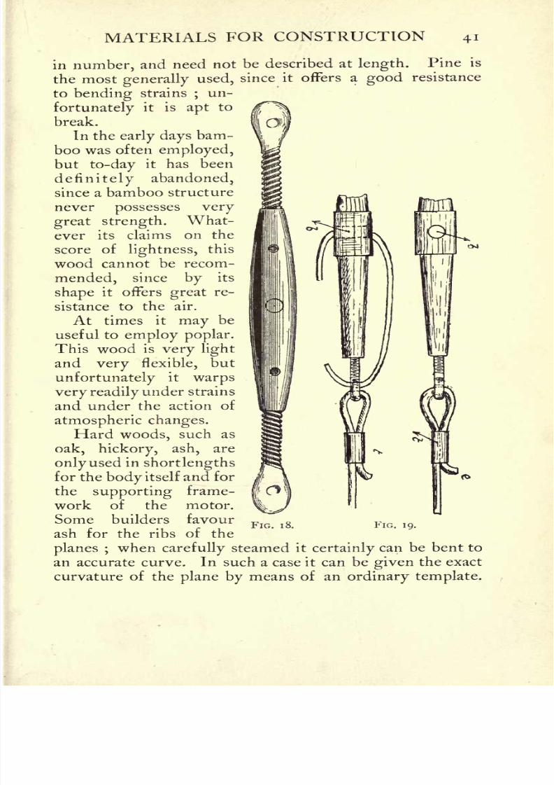
A wire-strainer simply consists of a bronze screw-nut
with two threads, one at either end, into which enter two
screws provided with eyelets,to which are attached the
ends of the wire to be stretched;the wire is strained by
means of a gudgeon in the nut. There are, of course,
a good many types of strainers, but their only pointof
difference is in the manner of threading. Figs. 17 and
1
8 show two different types ofstrainers. In order to
attach the wire as firmly as possible,it is first threaded
FIG. 17.
through a small piece of copper tubing /(fig. 19) ;
the
wire is then passed through theeyelet, bent, and the end
passed back through the tube /;the wire is then bent
back and cut. This method of fixing withstands the
greatest strains. In order to prevent the strainer from
becoming unscrewed, it is as well to thread a strong piece
of steel wire through the hole b and to pass it throughone of the eyelets.
(2)Wood
Wood is the most important material used in building
an aeroplane. The framework of the planes is usually
made of American pine, although, as will be shown later,
the planes are occasionally stretched over a frame built
entirely of metal. The varieties of wood used are few
8/6/2019 1910 howtobuildaeropl00petirich
http://slidepdf.com/reader/full/1910-howtobuildaeropl00petirich 61/150
8/6/2019 1910 howtobuildaeropl00petirich
http://slidepdf.com/reader/full/1910-howtobuildaeropl00petirich 62/150
8/6/2019 1910 howtobuildaeropl00petirich
http://slidepdf.com/reader/full/1910-howtobuildaeropl00petirich 63/150
iMATERIALS FOR CONSTRUCTION 43
rolled round thejoints. By this method it is possible to
produce fullyas strong and rigid
a framework as bymeans of bolts or screws.
It frequently occurs that the wood for the construction
of the planes is not available in sufficient lengths ;in this
case several lengths have to be joined together. This is
accomplished by gluing severalstrips
one over the other
andalternating the
joints.The
stripsare then fixed with
a special insoluble glue and bound round with fabric.
A much simpler process, but by no means so strong,
consists in
bevellingthe extremities of the
lengthdown
FIG. 21.
to a very fine edge and sheathing them in a small alu-
minium sleeve, which is fixed in place by two small bolts.But this method cannot be recommended, since the
aluminium sleeve is very apt to crack when the plane is
subjected to a shock.
In every case the sections used are specially designedto decrease the resistance of the air
(fig. 21). These
special sections are produced by a machine known as a
moulding-machine, which consists of a revolving head
provided with several cutting blades, forming inprofile
the shape of the sectionrequired.
The spar is fed into
the machine, and the cutting blades, revolving at high
speed, remove all projecting portions.

8/6/2019 1910 howtobuildaeropl00petirich
http://slidepdf.com/reader/full/1910-howtobuildaeropl00petirich 64/150
44 HOW TO BUILD AN AEROPLANE
(3) Fabric
The surface of the planes is constituted by specially
prepared fabric of extreme lightness. Some builders, suchas MM. Zens, at one time attempted to cover their planeswith Chinese parchment,
1
but, apart from the fact that it is
easily torn, this material iseasily
affected by atmospheric
moisture, which renders it unserviceable. Rubbered cloth
ispractically
the only fabric employed at the present time.
It is vulcanised at a high temperature, which renders it
unaffected
bymoisture. In
Europeit is manufactured
bythe Continental Company, by Michelin, by the Gutta-
Percha Co. of Hanover, by Hutchinson & Co., the North
British Rubber Company, Messrs Dunlop, and Messrs
Spencer & Sons. Agas-tight and waterproof British
fabric, into whose composition, however, india-rubber
does not enter, is manufactured by Messrs Hart. It
should not exceed in weight 150 grammes (5^ oz.)
per sq. m.
1 In England, Mr A. V. Roe has used muslin-backed paper with
satisfactory results. EDS.
8/6/2019 1910 howtobuildaeropl00petirich
http://slidepdf.com/reader/full/1910-howtobuildaeropl00petirich 65/150
CHAPTER III
THE CONSTRUCTION OF PROPELLERS
I. Preliminary remarks
PROPELLER theories are nowadays very numerous, and
all have good points ;but unfortunately they do not agree
in their most important features, and should always be
looked upon with suspicion.
The best and only way to form any idea of the value of
a theory is to build a propellerin accordance therewith and
totry
it. The result will be conclusive. However, even
this method of procedure is open to argument, for it is
possiblein nearly every instance to point out some con-
structional error. It is therefore necessary, in choosinga modus operandi* to take one which follows most
closely
the theory from which it is deduced.
II. Procedure based on M. Drzewieckfs theory
As we have said, when calculatingthe dimensions of a
propellerfor our imaginary aeroplane,
1
it is for these
reasons that M. Drzewiecki's theory appears preferable.
We have always used it in making propellers, and we have
always had good results.
It has been shown how the general dimensions of a
propellershould be calculated, and it only remains, before
examining other ways of doing so, to show how the
formula obtained should be applied.
M. Drzewiecki explains in his book how the necessary1 See p. 15.
45

8/6/2019 1910 howtobuildaeropl00petirich
http://slidepdf.com/reader/full/1910-howtobuildaeropl00petirich 66/150
46 HOW TO BUILD AN AEROPLANE
templates may be obtained by means of a working draw-
ing similar to that infig.
22.
On a horizontal axis O A the
pitch constant Mis laid off,
which gives the point B. Onan axis perpendicular to O,
startingfrom this point, lengths
equal to ^M, M, 2M, jM, 5Mare marked, which give the
points i, 2, 3, 4, 5, 6, which
are thenjoined
to thepoint
B.
In this way are obtained lines
drawn at varying angles to the
vertical axis.
From these points i, 2, 3,
etc., with a radius equal to ^ of
the specific width of the blade,
calculated as explained in Chap-ter I., arcs are drawn on the
same side of the vertical axis as
the point B, which cut the lines
iB, 2B, etc., and horizontal lines
are drawn from the points of
intersection.
The same procedure is carried
out on the other sideof
the
\axis with the same centres, but
FIG. 22.
with a radius equal to J of thespecific width, and horizontal
lines are again drawn from the points of intersection.

8/6/2019 1910 howtobuildaeropl00petirich
http://slidepdf.com/reader/full/1910-howtobuildaeropl00petirich 67/150
THE CONSTRUCTION OF PROPELLERS 47
The fourth side of the templates, which are shown as
the shaded portions in the figure,is bounded by the
vertical line A.
The templates thus obtained are cut out in thin pieces
of wood, and the pointsa are marked upon them at a dis-
FIG. 23.
tance of of their width. They are numbered as on the
working plan, and fixed securely on the board P with their
plane perpendicular to that of P, and to the axis #j, which
is the projection of the arm of the blade.
All the points a mentioned above are placed on the
axis xy at the distances JM, M, 2M, etc., starting from
FIG. 24.
the point O, which thus becomes the centre of rotation
(fig. 23).
The templates,of course, must have been previously
curved to form segments of the circles obtained by tak-
ing O for the centre and the distances previously mentioned
as radii.
It will be seen that the edges CD of the templates form
a"table," which determines the shape of the propeller-

8/6/2019 1910 howtobuildaeropl00petirich
http://slidepdf.com/reader/full/1910-howtobuildaeropl00petirich 68/150
48 HOW TO BUILD AN AEROPLANE
blade;and after they have been trimmed down where
necessary,its construction can begin (fig. 24).
From this description it will bereadily understood why
we have said that Drzewiecki's theory, even if it contains
errors, is still preferable to the others;and how it is
possible to make templates by exactly following his work-
ing drawings.The above method does not give any curvature to the
blade. If it should be asked if the blades ought to be
curved like aeroplane surfaces, the answer iscertainly
in
the affirmative, because in both cases the surfaces act in
the same way and with the sameobject.
Tatin and Wegner von Dallwitz both say and we
agree with them that the blade should have aslight
concavity, which iseasily made, even in a completed screw,
if it is of wood, but where it is built up on a metal frame-
work the cross members should be given the designedcurvature from the beginning.
III. Other ways of designing propellers The Colliex
process
M. Colliex, the engineer of the Voisin Works, follows
an empirical method in designing hispropellers, and the
reader already knows what confidence to place in results
so obtained.
His method is as follows : The diameter and pitch of
the propeller are determined by previously known examples,
and the first step is taken by finding the inclination of the
blades at any distance R from the centre. A horizontal
line OC is then drawn equal to the circumference of the
circle described by thetip
of the blade and the dimension
of the pitch drawn perpendicularly at C. In this way the
point D is obtained, from which the horizontal line DGcan be drawn. Now if it is required to know the inclina-
tion of the blade at its extremity, join DO, and the angle
tfjformed by DO, OC gives the answer.
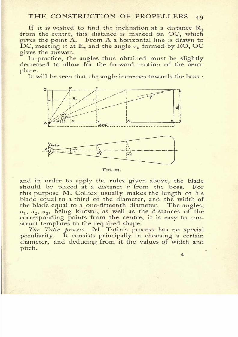
8/6/2019 1910 howtobuildaeropl00petirich
http://slidepdf.com/reader/full/1910-howtobuildaeropl00petirich 69/150
THE CONSTRUCTION OF PROPELLERS 49
If it is wished to find the inclination at a distance Rjfrom the centre, this distance is marked on OC, which
gives the point A. From A a horizontal line is drawn to
DC, meeting it at E, and the angle an formed by EO, OCgives the answer.
Inpractice,
the angles thus obtained must beslightly
decreased to allow for the forward motion of the aero-
plane.
It will be seen that the angle increases towards the boss;
FIG. 25.
and in order to apply the rules given above, the bladeshould be placed at a distance r from the boss. For
this purpose M. Colliex usually makes the length of his
blade equal to a third of the diameter, and the width of
the blade equal to a one-fifteenth diameter. The angles,
ai>
a2'
as> being known, as well as the distances of the
corresponding points from the centre, it is easy to con-
struct templates to the required shape.
The Tatin process M. Tatin's process has nospecial
peculiarity.It consists principally
in choosing a certain
diameter, and deducing from it the values of width and
pitch.
4
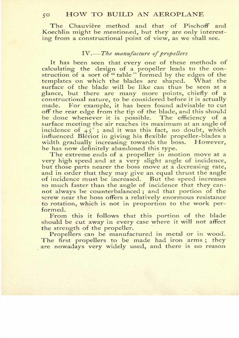
8/6/2019 1910 howtobuildaeropl00petirich
http://slidepdf.com/reader/full/1910-howtobuildaeropl00petirich 70/150
50 HOW TO BUILD AN AEROPLANE
The Chauviere method and that of Pischoff and
Koechlin might be mentioned, but they are only interest-
ing from a constructional point of view, as we shall see.
IV. The manufacture ofpropellers
It has been seen that every one of these methods of
calculating the design of a propeller leads to the con-
struction of a sort of"table
"formed by the edges of the
templates on which the blades are shaped. What the
surface of the blade will be like can thus be seen at a
glance, but there are many more points, chieflyof a
constructional nature, to be considered before it is actually
made. For example, it has been found advisable to cut
off the rear edge from thetip
of the blade, and this should
be done whenever it is possible.The efficiency
of a
surface meeting the air reaches its maximum at an angle of
incidence of 45 ;and it was this fact, no doubt, which
influenced Bleriot in giving his flexible propeller-blades a
width gradually increasingtowards the boss. However,
he has nowdefinitely
abandoned this type.
The extreme ends of a propellerin motion move at a
very high speed and at a very slight angle of incidence,
but those parts nearer the boss move at a decreasing rate,
and in order that they may give an equal thrust the angle
of incidence must be increased. But the
speed
increases
so much faster than the angle of incidence that they can-
not always be counterbalanced;and that portion of the
screw near the boss offers arelatively
enormous resistance
to rotation, which is not in proportion to the work per-
formed.
From this it follows that this portion of the blade
should be cut away in every case where it will not affect
the strength of the propeller.
Propellers can be manufactured in metal or in wood.
The first propellers to be made had iron arms; they
are nowadays very widely used, and there is no reason

8/6/2019 1910 howtobuildaeropl00petirich
http://slidepdf.com/reader/full/1910-howtobuildaeropl00petirich 71/150
THE CONSTRUCTION OF PROPELLERS 51
why they should not continue to be so, as they can
easily be improved in many ways. At the presentmoment they are used by the Voisin Brothers, Esnault-
Pelterie, the Antoinette Company, Bleriot, and manyothers.
(a)Metal propellers A flat steel arm is made and
pierced with holes corresponding to those in the blade,
which has previously beensuitably shaped on the tem-
plates, and the two are then riveted together with copperrivets. Both blades having been
similarly treated, it onlyremains to fix them in their
place, andfor this
purposethe steel arms have rectangular or triangular ends, which
FIG. 26
are fixed in a collar by means of a cotter and nut. The
collar can vary considerably in its form, and must bemade so as to fit firmly on the motor shaft
(fig. 26). In
the sketch it should be noticed that the propeller arms
areparallel, and not in the same
straight line. In manytypes, however, arms are situated along the same diameter,
as in the Esnault-Pelterie and Antoinettepropellers (figs.
27 and 28).
In our opinion, the best metal to use for the surface of
the blades is sheet aluminium, as it can be used in com-
paratively great thicknesses on account of itslightness,
and this tends to increase the moment of inertia of the
section of the blade, and in consequence to preserve its

8/6/2019 1910 howtobuildaeropl00petirich
http://slidepdf.com/reader/full/1910-howtobuildaeropl00petirich 72/150
52 HOW TO BUILD AN AEROPLANE
shape. We have seen that the blades are attached to the
arms by copper rivets, a great number of which, of course,
must be used to form a solid structure. In order partly
FIG. 27. FIG. 28.
to avoid this
lengthy operation,
M.Rudolph Chilling-worth of Nurnberg has patented the device shown in
figs.
29 and 30. The propeller-blade is cut out of sheet metal,
FIG. 29.
with two tongues at its base, which are folded over and
welded to the arm. In this way only a few rivets are
necessary to attach the arm to the surface of the blade.
Often the two blades are cut all in one piece, but this
method is open toobjection
on account of thedifficulty

8/6/2019 1910 howtobuildaeropl00petirich
http://slidepdf.com/reader/full/1910-howtobuildaeropl00petirich 73/150
THE CONSTRUCTION OF PROPELLERS 53
inattaching the propeller^
to the motor shaft. Wecannot pass over the name of M. Chillingworth without
mentioninganother
patentof his for
making pro-pellers.
The blades are fashioned as before out of one
sheet of metal, but are reinforced over a part of their
surface by a wooden facing, which is attached to the
metal
by
a kind of circular
copper
rim riveted to the
blade. This method makes use of the bestquality
possessed by wood, which is its resistance to bendingstress
(fig. 31).
(b) Wooden propellers There are a certain number of
FIG. 31.
drawbacks inherent in metal propellers. They are heavyand easily bent, and because of their great elasticity theyvibrate
whenin use. If
theyburst
under thestrain
ofhigh velocity,
the pieces are a great source of danger. It
is a matter of somedifficulty
to attach the blade to the
arm, and the rear face, however well it may be constructed,
cannot be made to show an even surface. For this reason

8/6/2019 1910 howtobuildaeropl00petirich
http://slidepdf.com/reader/full/1910-howtobuildaeropl00petirich 74/150
54 HOW TO BUILD AN AEROPLANE
it is easier to make wooden propellers, as they have
advantages which make them preferable to the others.
Wood has greater tensile strength than the best nickel-
steel. With the grain running lengthways to the blade,
the danger of its flyingto pieces under centrifugal force
is reduced to a minimum.
Its lightnessallows the blade to be very thick
through, and to be shaped in such a way as to offer
the least possible resistance to motion. There is,
moreover, another advantage arising from the fact that
the moment of inertia increases as the square of the
thickness, so that the propeller will offer a great re-
sistance to flexure and can be run at a very high rate
of speed. In the event of its breaking, the pieces,
being of no great mass, possess very little force, and
are generallyharmless.
The only drawback of these propellers is thedifficulty
of their construction, which makes them very expensive.
The best-known makers are Messrs Chauviere, PischofF,
and Koechlin. They can be made in one piece like
those of Messrs Wright and of M. PischofF, or in super-
posed thicknesses or laminae like those of M. Chauviere.
Both methods require great skill and give good results.
On the whole, however, we believe the latter method to
be the better, as it allows the choice of the firstquality
wood without any flaws to impair their strength ; but it
necessitates the use of special insoluble glue to unite the
pieces securely.
The method of construction is as follows : On an axis
xy are threaded thin stripsof wood, i, 2, and
3, cut out
according to the dimensions of thepropeller. They are
superposed as shown infig. 32 and glued together. The
projecting edges
are then cut
awayalong the lines aa^ bb,
after which the blades have to be shaped in accordance
with the templates. Although this method of construc-
tion may appear simple, it is inreality extremely difficult,
for the smallest irregularityaffects the
efficiencyof the

8/6/2019 1910 howtobuildaeropl00petirich
http://slidepdf.com/reader/full/1910-howtobuildaeropl00petirich 75/150
THE CONSTRUCTION OF PROPELLERS 55
propeller to an enormous degree. When the blades have
been shaped, they are polished and varnished.
It is obvious that the best shape of blade is that giving
a cross section which combines strength with the least
resistance to forward motion.
Sir Hiram Maxim has shown that the section illustrated
FIG. 32.
infig. 32 is the best for this purpose. Its greatest
thickness lies at about one-fourth of its width from
the forward edge, where the greatest pressure is applied.
Although we think it desirable to make bb slightly
concave, several well-known engineers are opposed to
this opinion.
(c)Framework propellers In addition to the foregoing,
a third class of propellersmust be mentioned. In this

8/6/2019 1910 howtobuildaeropl00petirich
http://slidepdf.com/reader/full/1910-howtobuildaeropl00petirich 76/150
56 HOW TO BUILD AN AEROPLANE
case the blades are formed by arms and cross-members
covered with fabric. The first propellers of this type were
made by Colonel Charles Renard in connection with his
dirigible balloon experiments.1
They were formed by two
lengths of steel tubing fixed to the axis of rotation at two
different points. The cross-members over which the
fabric is stretched are given a curve suitable to the heli-
coidal surface. M. Tatin has designed propellers of this
type forexisting dirigibles.
In some cases the cross-
members over which the fabric is stretched are only
supported by
a
single
steel tube.
FIG. 33.
(d) Other types of propellers Types of propellers can
be multiplied ad infinitum, so that we are unable to
refer to them all. Mention should, however, be made of
the propeller with flaccid blades, which actsolely through
the action ofcentrifugal force. The blades consist of
stripsof fabric, to the extremities of which are attached
iron weights. When set in motion the weights, under the
action of centrifugal force, cause the blades to assume their
proper shape.
Major von Parseval actually uses this type in his
dirigibles.It is sometimes thought that these flaccid
1 This type of propeller for aeroplane experiments was made in
England by Stringfellow about thirty years before Renard. EDS.

8/6/2019 1910 howtobuildaeropl00petirich
http://slidepdf.com/reader/full/1910-howtobuildaeropl00petirich 77/150
THE CONSTRUCTION OF PROPELLERS 57
propellers possess the advantage of a variable pitch, but,
in our opinion, this would not counterbalance the detri-
mental effect of the pockets which are formed in the
B
V'A
FIG. 34.
fabric during rotation. Atany rate, the type is very little
used;the firm of August Riedinger of Augsburg has
patented a mixed type which, nevertheless, seems to
possess good points.
8/6/2019 1910 howtobuildaeropl00petirich
http://slidepdf.com/reader/full/1910-howtobuildaeropl00petirich 78/150
CHAPTER IV
THE ARRANGEMENTS FOR STARTING AND LANDING
I. General remarks
AN essential condition in a flying-machine is itsability
to
leave the ground under its own power ;and in order
that it may do so quickly,as well as for ease in trans-
portation,it should be able to move
easily over the ground
up to the moment ofrising.
Thus it isnecessary to
provide some means wheels or skids on which the
machine may be readily moved about. These wheels or
skids should be fixed to the chassis, which must be so
arranged as to absorb the entire shock oflanding. The
chassis, moreover, must be flexible and capable of move-
ment in any direction, for an aeroplane whentravelling
over the ground meets with all sorts of obstacles and is
often turned out of itsstraight course. The wheels
should therefore be capable of adapting themselves to
circumstances. It is clear, then, that it is not easy to
build a good chassis, and that the materials used must be
of the first quality, strong andlight.
Some few pilots employ a system of a rail and a tower
or pylon,and launch their machines by means of a
falling
weight. In our opinion, however, this method will not
survive, and we only mention it inpassing.
II. Wheeled chassis
The most general way of mounting chassis is on wheels,
set like castors, free to move in all directions. The types
58
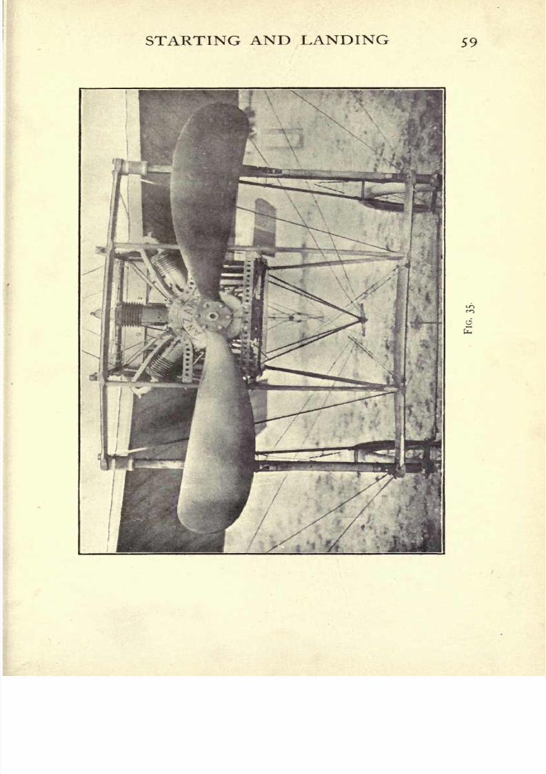
8/6/2019 1910 howtobuildaeropl00petirich
http://slidepdf.com/reader/full/1910-howtobuildaeropl00petirich 79/150

8/6/2019 1910 howtobuildaeropl00petirich
http://slidepdf.com/reader/full/1910-howtobuildaeropl00petirich 80/150
60 HOW TO BUILD AN AEROPLANE
of chassis are so numerous that they cannot all be described
in detail, so we will only mention those which are most
widely used and those fitted to well-known machines.
(a) The Voisin chassis(fig. 37) The Voisin chassis is
the oldest now in use, and consists of arigid rectangular
frame of steel tubing. The longer sides of this frame are
parallel to the ground, while the others carry the two forks
which hold the wheels, and can movefreely in every
direction. Two steel tubes fixed to the frame unite it
firmly to the fuselage, and at the same time act as re-
ceptacles for powerful shock-absorbers in the shape, of
FIG. 36.
helicoidal springs. To ensure rigidity it is trussed withtension-wires. As the wheels would not run
parallel if
the forks were free to turnindependently, the hubs are
united by a jointed rod, and tension springs are stretched
diagonally from the hubs to the framework.
This chassis has given abundant proof of itsreliability,
and has been adopted by many of the leading aviators.
(b)The Bleriot chassis
(fig. 36) Simplicity is the chief
feature of the chassis made by the hero of the Channel
crossing. The main frame is of hard wood, and carries
two steel tubes on which the wheel-forks slide. A jointedrod similar to that described above keeps the wheels

8/6/2019 1910 howtobuildaeropl00petirich
http://slidepdf.com/reader/full/1910-howtobuildaeropl00petirich 81/150
STARTING AND LANDING 61

8/6/2019 1910 howtobuildaeropl00petirich
http://slidepdf.com/reader/full/1910-howtobuildaeropl00petirich 82/150
62 HOW TO BUILD AN AEROPLANE
running parallel.Another type is also shown in the
figure, which, though quite good, is not so often used.
Its extreme simplicity does not warrant explanation.
(c) The Antoinette chassis (figs. 38 and 39) TheAntoinette aeroplane is mounted on two wheels placedclose together and secured
rigidlyto the framework. Ad-
FIG. 38.
ditional support is provided by buffers projecting beneath
the wings (see fig. 39). As this arrangement would be
toorigid to absorb the shock of landing, two long wooden
shock-absorbers are added in front of the wheels, which
touch the ground before they do, and ease the descent. 1
1 The chassis has undergone considerable alterations since the
above was written. The buffers have been discarded, and the wheels
placed further apart. EDS.

8/6/2019 1910 howtobuildaeropl00petirich
http://slidepdf.com/reader/full/1910-howtobuildaeropl00petirich 83/150
STARTING AND LANDING 63
Such are the chief types of wheeled chassis. They are
always constructed of steel tubing, as that has been found
to be the best material for the purpose. Their assembling
must, however, be conducted with care, on account of the
great strains which they have to undergo. This is done
in several ways : either by inserting the ends of the tubes
in cast-iron angle brackets and brazing thembicycle-
fashion, or by acetylene-welding the tubes together.
FIG. 39.
In the Esnault-Pelterieworkshops
the latter
methodis always used, with the result that R.E.P. monoplaneshave a reputation for
rigidity.The German Jatho aero-
plane is entirely constructed by this process.
Another excellent chassis is that used on M. Karl
Hippsich's aeroplane at Bremen. It is composed of two
wheels on a common axle, with two rods carrying shock-
absorbers, which are both inclined towards the centre of
the machine, so that if the landing takes place on one
wheel, the shock is taken orthogonally by the spring and
sustained equally by the whole machine. If a normal
landing on both wheels is made, the same result obtains.
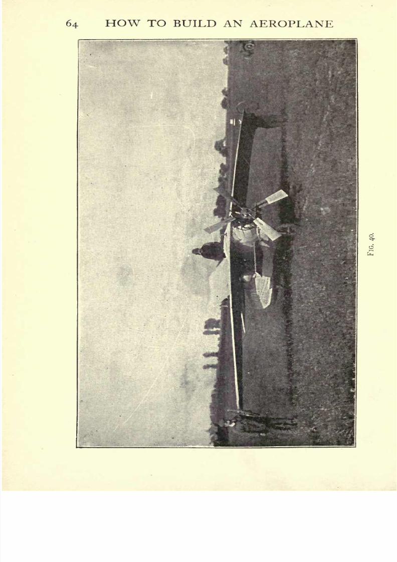
8/6/2019 1910 howtobuildaeropl00petirich
http://slidepdf.com/reader/full/1910-howtobuildaeropl00petirich 84/150
64 HOW TO BUILD AN AEROPLANE
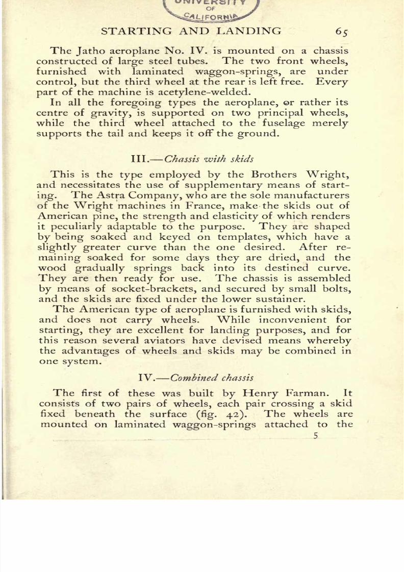
8/6/2019 1910 howtobuildaeropl00petirich
http://slidepdf.com/reader/full/1910-howtobuildaeropl00petirich 85/150
STARTING AND LANDING 65
The Jatho aeroplane No. IV. is mounted on a chassis
constructed of large steel tubes. The two front wheels,
furnished with laminatedwaggon-springs,
are under
control, but the third wheel at the rear is left free. Every
part of the machine is acetylene-welded.
In all the foregoing types the aeroplane, r rather its
centre ofgravity, is supported on two principal wheels,
while the third wheel attached to the fuselage merely
supports the tail and keeps it off the ground.
III. Chassis with skids
This is the type employed by the Brothers Wright,and necessitates the use of supplementary means of start-
ing.The Astra Company, who are the sole manufacturers
of the Wright machines in France, make the skids out of
American pine, the strength and elasticityof which renders
it
peculiarly adaptableto the
purpose. Theyare
shapedby being soaked and keyed on templates, which have a
slightly greater curve than the one desired. After re-
maining soaked for some days they are dried, and the
wood gradually springs back into its destined curve.
They are then ready for use. The chassis is assembled
by means of socket-brackets, and secured by small bolts,
and the skids are fixed under the lower sustainer.
The American type of aeroplane is furnished with skids,
and does not carry wheels. While inconvenient for
starting, they are excellent for landing purposes, and for
this reason several aviators have devised means wherebythe advantages of wheels and skids may be combined in
one system.
IV. Combined chassis
The first of these was built by Henry Farman. It
consists of twopairs
of wheels, each pair crossing a skid
fixed beneath the surface(fig. 42). The wheels are
mounted on laminated waggon-springs attached to the
5
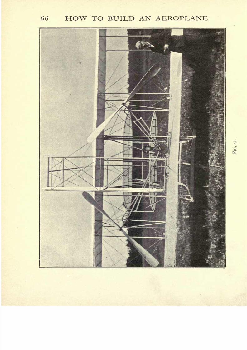
8/6/2019 1910 howtobuildaeropl00petirich
http://slidepdf.com/reader/full/1910-howtobuildaeropl00petirich 86/150
66 HOW TO BUILD AN AEROPLANE
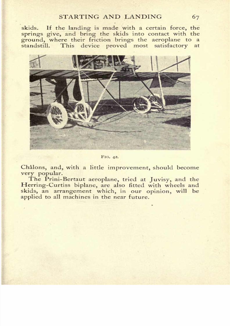
8/6/2019 1910 howtobuildaeropl00petirich
http://slidepdf.com/reader/full/1910-howtobuildaeropl00petirich 87/150
STARTING AND LANDING 67
skids. If the landing is made with a certain force, the
springs give, and bring the skids into contact with the
ground, where their friction brings the aeroplane to a
standstill. This device proved mostsatisfactory
at
FIG. 42.
Chalons, and, with a little improvement, should become
very popular.The Prini-Bertaut aeroplane, tried at Juvisy, and the
Herring-Curtiss biplane, are also fitted with wheels and
skids, an arrangement which, in our opinion, will be
applied to all machines in the near future.
8/6/2019 1910 howtobuildaeropl00petirich
http://slidepdf.com/reader/full/1910-howtobuildaeropl00petirich 88/150
CHAPTER V
THE FUSELAGE BUILDING-IN THE MOTOR THE CONTROLS
I. Necessary qualities of the fuselage
WE have now arrived at the most important part of an
aeroplane,the fuselage.
1It is to this part that the chassis,
the sustainers, the motor, the control levers, thepilot seat,
and the controls are fixed. It ought therefore to be capable
of sustaining any strain, for it is the body, so to speak, of
the bird.
It is most important that a well-built fuselage should be
indifferent to vibration, be able to resist bending strain,
and suffer great shocks without damage. The assembling
of its constituent parts must be done in the strongest
manner possible,for the construction of the fuselage is of
as much importance as that of the aeroplane proper.
II. Various types offuselage Their manufacture
A fuselageis in fact only a built-up girder, like that
used in many other constructional operations. In aviation,
however, it must be able to stand an equal strain, and at
the same time be very much lighter than when used in
other structures. For this reason its construction presents
a very nice problem.
Under different manufacturers they assume various
shapes,which are influenced by the position of the pro-
1
Fuselage is the term generally used to denote the body of the
aeroplane. EDS.
68

8/6/2019 1910 howtobuildaeropl00petirich
http://slidepdf.com/reader/full/1910-howtobuildaeropl00petirich 89/150
THE FUSELAGE 69
peller.If the propeller is in rear of the surfaces, provision
must be made for its revolution, as in the Voisin biplanes.
The fuselage consists essentially of four members, joined
by ties, and trussed by steel wire and strainers. Both
wood and steel are used in its manufacture.
A wooden fuselage islighter
and quite as strong as a
steel one, but is more expensive, owing to thedifficulty
of
construction.
It is made either in triangular or square section, and in
both cases the same methods are employed.
(a) Wooden fuselage The templates, cut according tothe plans, are secured temporarily on a very strong spar.
Other rods forming the longitudinal members of the fuse-
lage are bent along the templates, fittingin the notches
left for this purpose. These rods are then tied with
carefully chosen pieces of wood, sectionally and diagonally,
to meet every possible strain(fig. 43).
After the ties have been placed inposition,
the whole
frame is assembled in the way invented by Ader and
Espinoza, which has been referred to in a previous chapter.
This consists of winding fabric coated with glue round the
joints. When the whole is dry, the templates are taken
out and other ties inserted in such a way as to consolidate
the whole structure.Finally, several coats of varnish are
applied (fig. 44).
In this way very long fuselages and truncated fuselages
are built : the former serve as the main body of the whole
machine, while the latter only contain the motor and the
control levers.
MM. PischofF and Koechlin have built their monoplaneswith fuselages which may be compared to the hull of a motor
boat(fig. 45). It is an excellent type in point of strength,
but its
weight
is often excessive. Some manufacturers
build their fuselages inquite a simple way, as follows :
The four longitudinal members have aluminium sockets
attached to them, in which the ends of the lateral members
fit. By this means the upper and lower constructions of

8/6/2019 1910 howtobuildaeropl00petirich
http://slidepdf.com/reader/full/1910-howtobuildaeropl00petirich 90/150
70 HOW TO BUILD AN AEROPLANE

8/6/2019 1910 howtobuildaeropl00petirich
http://slidepdf.com/reader/full/1910-howtobuildaeropl00petirich 91/150
THE FUSELAGE 71
the fuselage are built up separately.It is easy enough
when they have been completed to place one on the other
and tojoin them. Wire
staysare attached to the eye-
bolts which fasten the sockets to the main members, andensure the
rigidityof the whole. It may be remarked
FIG. 44.
that this method is only easily applied to fuselages with
not less than four sides.
In constructing a triangular fuselage, particularcare
must be taken to prevent weakening the sections of the
lower member, which is caused by the insertion of a large
number of bolts in each of them. In addition, it wouldbe necessary to pierce sockets in some of the types,
or
otherwise the bolts will not be placed regularlyas in the
case of a quadrangular fuselage.

8/6/2019 1910 howtobuildaeropl00petirich
http://slidepdf.com/reader/full/1910-howtobuildaeropl00petirich 92/150
72 HOW TO BUILD AN AEROPLANE
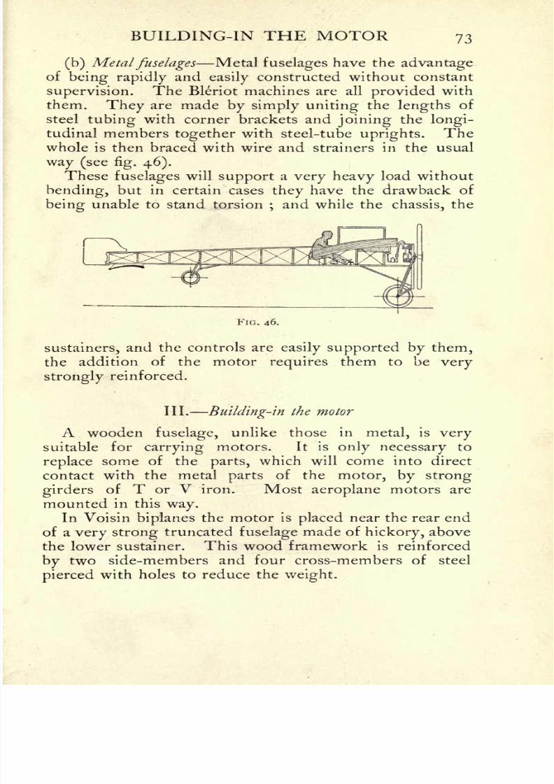
8/6/2019 1910 howtobuildaeropl00petirich
http://slidepdf.com/reader/full/1910-howtobuildaeropl00petirich 93/150
BUILDING-IN THE MOTOR 73
(b) Metalfuselages Metal fuselages have the advantageof being rapidly and
easily constructed without constant
supervision. The Bleriot machines are all provided with
them. They are made by simply uniting the lengths of
steel tubing with corner brackets and joining the longi-
tudinal members together with steel-tube uprights.The
whole is then braced with wire and strainers in the usual
way (see fig. 46).
These fuselages will support a very heavy load without
bending, but in certain cases they have the drawback of
beingunable to stand torsion
;and while the
chassis,the
FIG. 46.
sustainers, and the controls are easily supported by them,
the addition of the motorrequires them to be very
strongly reinforced.
III. Building-in the motor
A wooden fuselage,unlike those in metal, is very
suitable for carrying motors. It is only necessary to
replace some of theparts, which will come into direct
contact with the metal parts of the motor, by strong
girdersof T or V iron. Most aeroplane motors are
mounted in this way.In Voisin biplanes the motor is placed near the rear end
of a very strong truncated fuselage made of hickory, above
the lower sustainer. This wood framework is reinforced
by two side-members and four cross-members of steel
pierced with holes to reduce the weight.
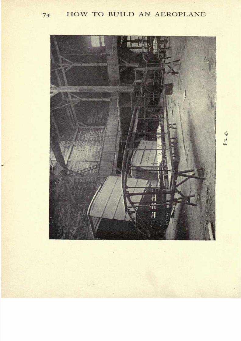
8/6/2019 1910 howtobuildaeropl00petirich
http://slidepdf.com/reader/full/1910-howtobuildaeropl00petirich 94/150
74 HOW TO BUILD AN AEROPLANE
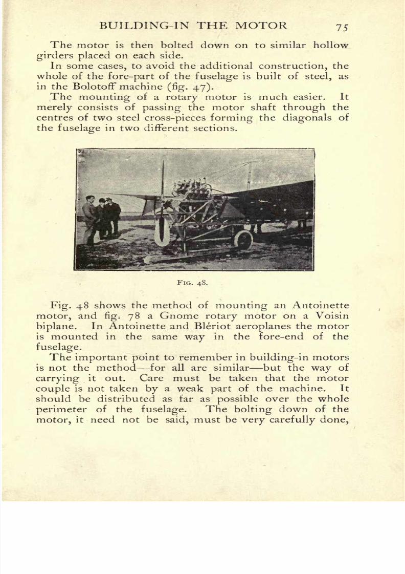
8/6/2019 1910 howtobuildaeropl00petirich
http://slidepdf.com/reader/full/1910-howtobuildaeropl00petirich 95/150
BUILDING-IN THE MOTOR 75
The motor is then bolted down on to similar hollow
girders placed on each side.
In some cases, to avoid the additional construction, the
whole of the fore-part of the fuselage is built of steel, as
in the BolotofF machine(fig. 47).
The mounting of a rotary motor is much easier. It
merely consists of passing the motor shaft through the
centres of two steel cross-pieces forming the diagonals of
the fuselagein two different sections.
P'lG. 48.
Fig. 48shows the method of
mountingan Antoinette
motor, andfig. 78 a Gnome rotary motor on a Voisin
biplane. In Antoinette and Bleriot aeroplanes the motor
is mounted in the same way in the fore-end of the
fuselage.
The important point to remember in building-in motors
is not the method for all are similar but the way of
carrying it out. Care must be taken that the motor
couple is not taken by a weak part of the machine. It
should be distributed as far as possible over the whole
perimeter of thefuselage.
The bolting down of the
motor, it need not be said, must be very carefully done,
8/6/2019 1910 howtobuildaeropl00petirich
http://slidepdf.com/reader/full/1910-howtobuildaeropl00petirich 96/150
76 HOW TO BUILD AN AEROPLANE
and frequently overhauled. A loose bolt in sofragile
a framework may easily cause disaster.
The Wright motor is very simply mounted on two
stout pieces of wood attached to the lower sustainer.
This arrangement does away with the need for any
fuselage, and only requires the sustainer to be strengthened
where the motor rests. It must not be forgotten, how-
ever, that while it may be quite adequate on a Wright
aeroplane, this mounting would not do on all machines.
Most aeroplanes are driven by asingle propeller, which
sets
upa tremendous
torquewith its lever
point
on the
motor bed. If this point is situated on the sustainers
they very soon wear out. It is notquite
the same in the
case of the Wright machine, although even there the con-
tingency exists to a certain extent.
However, this way of mounting motors is not. likelyto
endure in the future, and is only convenient for experi-
mental work.
IV. Arrangement of the controls
The various movements of aeroplanes in the vertical
and horizontal plane are brought about by alteringthe
angle of incidence of certain surfaces, which are hingedand moved in the required direction by lever or wheel
controls.
The rudder planes are stretched on framework, and are
easilycontrolled by cables led over small
pulleys and con-
nected with arms rigidlyattached to their surfaces and
projecting from each side. By moving them so as to
oppose a portion of their surface to the wind, thepilot
is
able to guide the machine. This movement is accom-
plished by levers, which are capable of very easy and
delicate operating.
Either hand or foot control can be used. The former
is generally reserved for warping the surfaces, or for
operating the ailerons, upon which the lateralstability
de-
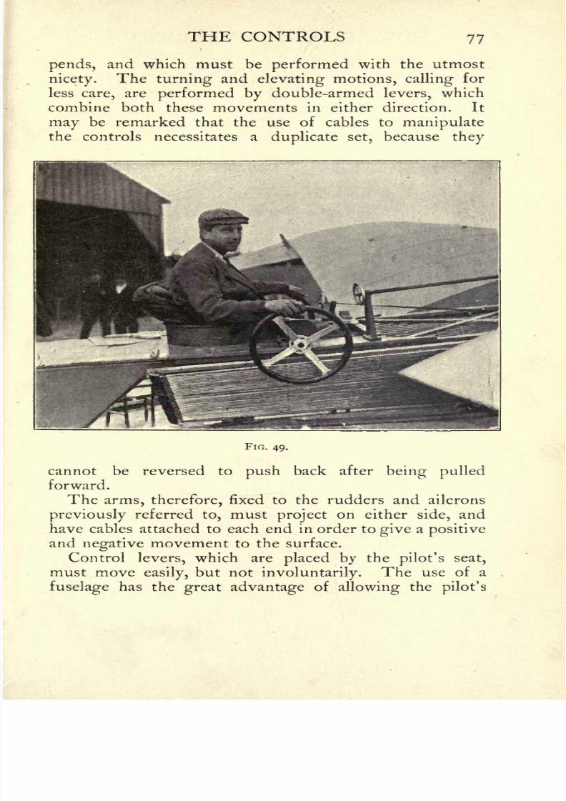
8/6/2019 1910 howtobuildaeropl00petirich
http://slidepdf.com/reader/full/1910-howtobuildaeropl00petirich 97/150
THE CONTROLS 77
pends, and which must be performed with the utmost
nicety. The turning and elevating motions, callingfor
less care, are performed by double-armed levers, which
combine both these movements in either direction. It
may be remarked that the use of cables to manipulatethe controls necessitates a duplicate set, because they
FIG. 49.
cannot be reversed to push back after being pulled
forward.
The arms, therefore, fixed to the rudders and ailerons
previously referred to, must project on either side, and
have cables attached to each end in order to give a positive
and negative movement to the surface.
Control levers, which are placed by thepilot's seat,
must moveeasily,
but not involuntarily. The use of a
fuselage has the great advantage of allowing thepilot's

8/6/2019 1910 howtobuildaeropl00petirich
http://slidepdf.com/reader/full/1910-howtobuildaeropl00petirich 98/150

8/6/2019 1910 howtobuildaeropl00petirich
http://slidepdf.com/reader/full/1910-howtobuildaeropl00petirich 99/150
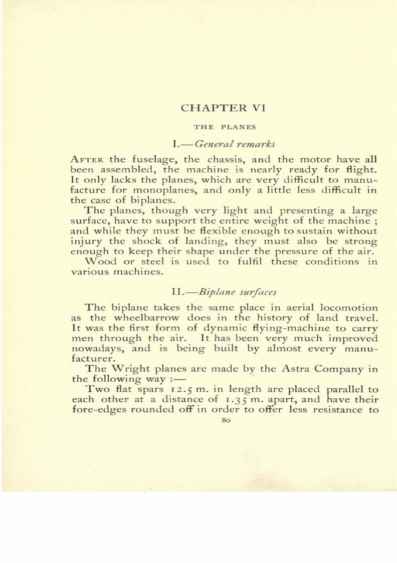
8/6/2019 1910 howtobuildaeropl00petirich
http://slidepdf.com/reader/full/1910-howtobuildaeropl00petirich 100/150
CHAPTER VI
THE PLANES
I. General remarks
AFTER the fuselage, the chassis, and the motor have all
been assembled, the machine is nearly ready forflight.
It only lacks the planes, which are very difficult to manu-
facture for monoplanes, and only a little less difficult in
the case ofbiplanes.
The planes, though very lightand presenting a
large
surface, have to support the entire weight of the machine;
and while they must be flexible enough to sustain without
injury the shock of landing, they must also be strong
enough to keep their shape under the pressure of the air.
Wood or steel is used to fulfil these conditions in
various machines.
II. Biplane surfaces
The biplane takes the same place in aerial locomotion
as the wheelbarrow does in the history of land travel.
It was the first form of dynamic flying-machine to carry
men through the air. It has been very much improved
nowadays, and is being built by almost every manu-
facturer.
The Wright planes are made by the Astra Company in
the following way:
Two flat spars 12.5m. in length are placed parallel to
each other at a distance of 1.35 m.apart, and have their
fore-edges rounded off in order to offer less resistance to
80
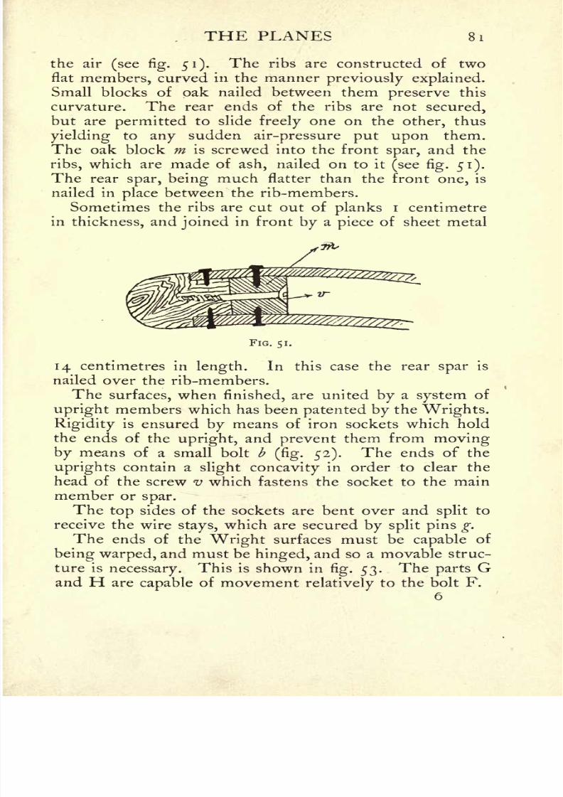
8/6/2019 1910 howtobuildaeropl00petirich
http://slidepdf.com/reader/full/1910-howtobuildaeropl00petirich 101/150
THE PLANES 81
the air(see fig. 51). The ribs are constructed of two
flat members, curved in the manner previously explained.
Small blocks of oak nailed between them preserve this
curvature. The rear ends of the ribs are not secured,
but are permitted to slide freely one on the other, thus
yielding to any sudden air-pressure put upon them.
The oak block m is screwed into the front spar, and the
ribs, which are made of ash, nailed on to it (see fig. 51).
The rear spar, being much flatter than the front one, is
nailed in place between the rib-members.
Sometimes the ribs are cut out of
planksi centimetre
in thickness, and joined in front by a piece of sheet metal
FIG. 51.
14 centimetres in length. In this case the rear spar is
nailed over the rib-members.
The surfaces, when finished, are united by a system of
upright members which has been patented by the Wrights.
Rigidityis ensured
bymeans of iron sockets which hold
the ends of the upright, and prevent them from moving
by means of a small bolt b(fig. 52). The ends of the
uprights contain aslight concavity in order to clear the
head of the screw v which fastens the socket to the main
member orspar.
The top sides of the sockets are bent over andsplit
to
receive the wirestays,
which are secured by split pins g.
The ends of the Wright surfaces must be capable of
being warped, and must be hinged, and so a movable struc-
ture isnecessary. This is shown in
fig. 53. The parts Gand H are capable of movement relatively
to the bolt F.
6
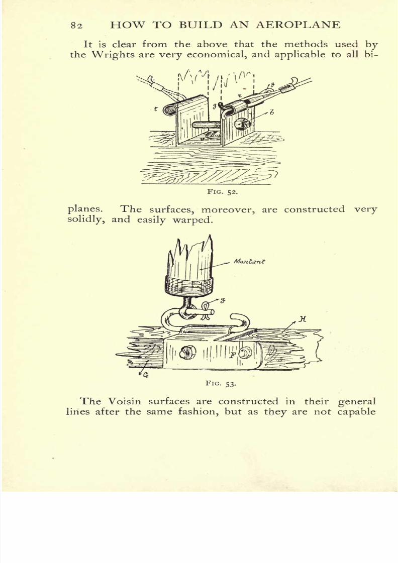
8/6/2019 1910 howtobuildaeropl00petirich
http://slidepdf.com/reader/full/1910-howtobuildaeropl00petirich 102/150
82 HOW TO BUILD AN AEROPLANE
It is clear from the above that the methods used bythe Wrights are very economical, and applicable to all bi-
FIG. 52.
planes. The surfaces, moreover, are constructed very
solidly, andeasily warped.
FIG. 53.
The Voisin surfaces are constructed in their general
lines after the same fashion, but as they are not capable
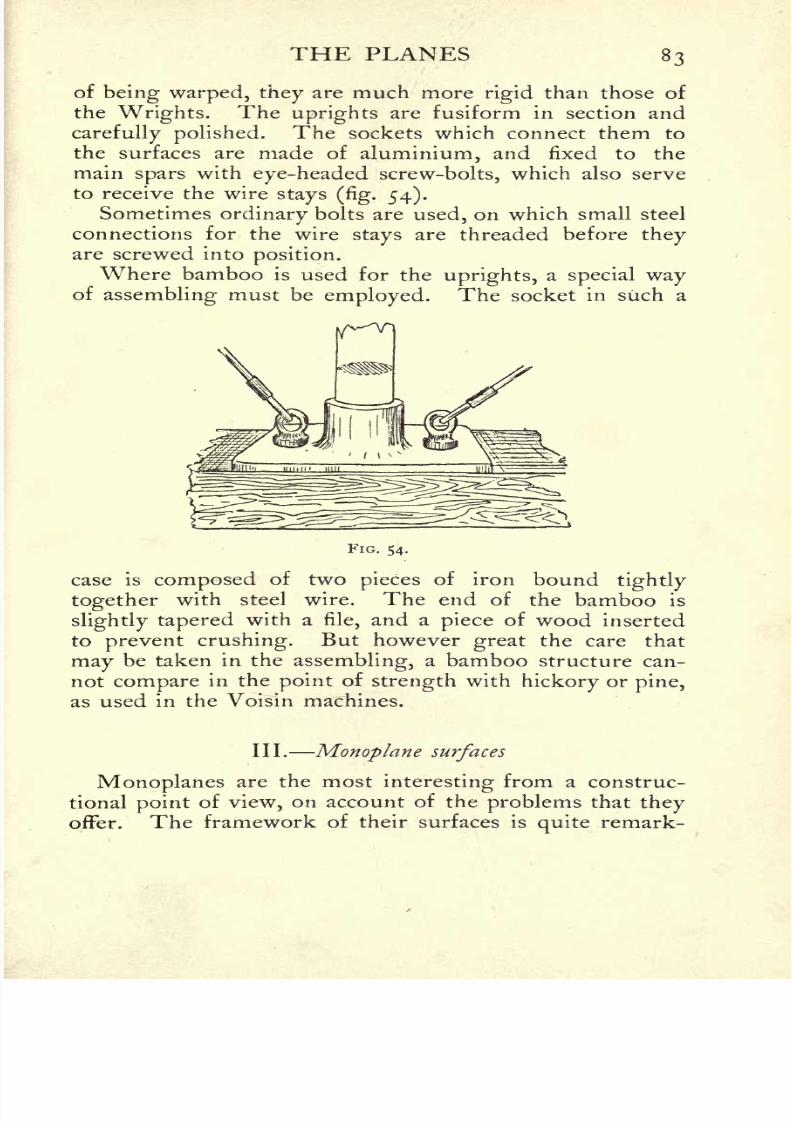
8/6/2019 1910 howtobuildaeropl00petirich
http://slidepdf.com/reader/full/1910-howtobuildaeropl00petirich 103/150
THE PLANES 83
of being warped, they are much morerigid than those of
the Wrights. The uprights are fusiform in section and
carefully polished. The sockets which connect them to
the surfaces are made of aluminium, and fixed to the
main spars with eye-headed screw-bolts, which also serve
to receive the wirestays (fig. 54).
Sometimes ordinary bolts are used, on which small steel
connections for the wire stays are threaded before theyare screwed into position.
Where bamboo is used for the uprights, a special wayof
assembling must be employed. The socket in such a
FIG. 54.
case is composed of two pieces of iron boundtightly
together with steel wire. The end of the bamboo is
slightly tapered with a file, and a piece of wood inserted
to prevent crushing. But however great the care that
may be taken in the assembling, a bamboo structure can-
not compare in the point of strength with hickory orpine,
as used in the Voisin machines.
III. Monoplane surfaces
Monoplanes are the mostinteresting
from a construc-
tional point of view, on account of the problems that theyoffer. The framework of their surfaces is quite remark-

8/6/2019 1910 howtobuildaeropl00petirich
http://slidepdf.com/reader/full/1910-howtobuildaeropl00petirich 104/150
84 HOW TO BUILD AN AEROPLANE
able. The surfaces have for a long time been made in
wood, and this method is still adopted in many cases, but
steel also has recently come into use.
The surfaces of the Antoinette monoplanes are entirely
made of wood, and all the cross members are of the same
thickness(fig. 55 shows the fineness of the construction).
The main spars are of sufficient length to allow them
to be joined together and secured to the fuselage.The
ribs in this case are composed of two thin ash laths, with
ties placed between them at intervals throughout their
entirelength.
In other machines it has been found better to cut them
out of solid wood and pierce them with holes. The wingsof the Bleriot monoplanes are built up of ribs cut from
wood 1.5 centimetres in thickness, which are inserted in
a strong steel tube, with one-third of their length project-
ing in front of it. In this case the steel tube performsthe same office as a propeller arm.
In order to strengthen the rear portion of the wing,
six transverse members are placed parallelto the steel
tube, and at the ends of the surfaces thinstrips
of curved
wood are placed, to which the covering is attached.
The Esnault-Pelterie machine is entirelybuilt up of
steel tubes of all thicknesses welded together. The Jatho
and the Hippsisch aeroplanes in Germany, of which we
have previously spoken,are
madein the same
way.After the wings have been made, they are fixed to the
aeroplane in such fashion as to unite them firmly to the
fuselage,and the connection reinforced by a system of
wire stays radiating from a mast in the fuselage. To
facilitate this, holes should be provided in the steel tubes
of the framework, or, better still, rings brazed on before
the covering is attached, so that the wire stays may be
fastened to them. The surfaces are covered with special
fabric of which we have spoken in the chapter on Materials.
The applicationof this fabric to the framework is an
extremely delicate operation, as it must be stretched evenly

8/6/2019 1910 howtobuildaeropl00petirich
http://slidepdf.com/reader/full/1910-howtobuildaeropl00petirich 105/150
THE PLANES 85
and present a smooth surface. There are several waysof doing this, either by gluing it on to the wooden edgesor by lacing it. Wright, who always uses simple methods,
merely nails the fabric on the cross spars and ribs, up-holsterer-fashion.
The operation of gluing the fabric must be performedwith care, as it is very difficult to
repair any mistakes.

8/6/2019 1910 howtobuildaeropl00petirich
http://slidepdf.com/reader/full/1910-howtobuildaeropl00petirich 106/150
86 HOW TO BUILD AN AEROPLANE,
It is excellent for the machines which are not likely to
undergo any alterations, but in general it is best that the
fabric should be laced. If this is done, when there is a
wing to be repaired the covering can be taken off, and
replaced afterwards. On the Voisin machine the whole
of the covering is laced, but only the tail of the Antoinette
is treated in this manner. The fabric of the wings is
stretched on, glued, and then varnished, in order to
minimise the skin friction.
In cases where the surfaces are warped, the direction in
which the threads of the fabric run is of importance.
The weft should lie parallelto the line of flexure. The
Wrights have adopted this method in their biplanes and
patented it.
When the fabric has been placed in position in a mono-
plane,it only remains to stay
the machine, which is done
by joining different points of the wing-surface to the
fuselage by steel wires;
this tends to preserve their shape
while in flight. These wires are often attached to the endof a very strong upright fixed in the
fuselage, as in the
case of Bleriot XL, in which the upright was a steel tube
with four supports.
IV. The curvature of the cross section of the wing-surfaces
We have not previously stated what form the ribs of
the wing-surfaces should take;
itis, however, of the
utmost importance, and a point upon which theefficiency
of the aeroplane depends. Formerly they were true
planes, containing no curve whatsoever. Experienceshowed later that the
lifting power under these conditions
is a great deal less than when the surfaces have a curve,
with its centre nearer the forward edge than the rear.
Nature herself provides us with an example of this in
the wing of a bird.
Lilienthal, the great German pioneer, was the first to
show the proper ratio between the arc of the curve and
8/6/2019 1910 howtobuildaeropl00petirich
http://slidepdf.com/reader/full/1910-howtobuildaeropl00petirich 107/150
THE PLANES 87
the surface. He gave it as one-twelfth of the width, and
expressed the opinion that the curve should reach its
highest point near the forward edge of the surface.
These figures were arrived at by studying birds, and inthe aeroplanes of Captain Ferber and the Wright Brothers
they have proved their value. However, we do not think
they ought to be accepted without reserve, for it is not
our purpose to copy birds. Nature has fashioned these
wonderful creatures, who, nevertheless, can only flywhen
they are perfect.If we copy them at
all, we must repro-
duce every part of them so as to obtain the same results,
but as we cannot do this, we must follow out our ownideas.
In our opinion,we ought not to copy the curve of a
bird's wings, because they are provided both forflapping
and gliding flight.No comparison can thus be made to
our aeroplanes,which only glide. Moreover, according
to Professor Marey, the head of a bird follows a sinuous
course, to allow for the variations in the relative positionsof the sustaining force and the centre of
gravity. The
wings, of course, reproduce this oscillation, which has no
parallelin aeroplanes.
It follows, then, that careful
experiments should be made before adopting a curved
surface. The work of a laboratory is better in certain
cases than the easier method of observing Nature, and the
results of the experiments of Sir Hiram Maxim are of
more value for aviation than the works of Marey,
Mouillard, or Pettigrew, interesting though they be. But
the curve of the sustaining surfaces has not the impor-tance with which it is usually credited.
The wings of the Antoinette are absolutely symmetrical
and are very efficient. What is of importance is theangle
of incidence of the plane.The same problem has
already
been faced in hydraulics and thermodynamics in thecase of steam- and water-turbines. The fluid, whether of
air or water, must flow regularly around the surface with-
out disturbing its continuity, and it mustsplit
the energy

8/6/2019 1910 howtobuildaeropl00petirich
http://slidepdf.com/reader/full/1910-howtobuildaeropl00petirich 108/150
88 HOW TO BUILD AN AEROPLANE
due to its velocityV into two
parts, the one producingresistance to forward motion, and the other giving lift.
A curvature of a proper shape should increase the latter
and decrease the former. Theair
should then leavethe
surface with the vertical velocity i;,so as not to interfere
with the following masses of air. In a word, for the
curve should be a good one, the air must be pressed
downwards as soon as it reaches the surface with this
constant velocity ;and in order to produce lift it ought to
possess a uniform acceleration, which will compensate v
and preserve its minimum value.
It is easy to reduce these considerations to an equation
giving a parabolic curve, which must have its highest
point near the forward edge. From this it can be seen
that the parabola, which already possesses astonishing
qualitiesboth in
optics and physics, retains them in
aviation also. In addition to those mentioned, one oc-
casionally meets with curves of an extraordinary nature,
arrived at by practical experiments, and sometimeswithout any theoretical grounds ;
but no good results
can ever be obtained by the construction of aeroplanes
on these lines.

8/6/2019 1910 howtobuildaeropl00petirich
http://slidepdf.com/reader/full/1910-howtobuildaeropl00petirich 109/150
CHAPTER VII
MOTORS
THEtheory
that the
aeroplane
motor must of
necessitybe of extreme lightness
is of ancient origin ;it was confirmed
by the late Colonel Renard, who expressed the opinion
that artificialflight
would only be rendered possible when
the weight of the motor was reduced toi|-
kilos (3.3 Ibs.)
per HP. Even at the present time many engineers sacrifice
reliabilityto
lightness,with the consequence that the
working of the motor is seriously affected. When will it
be understood that the best motor for an aeroplane is the
ordinary motor-car engine, with its weight suitably re-
duced ? Figures are the best proof. At Le Mans, Wilbur
Wright flew with a passenger weighing 100 kilos (220 Ibs.)
by means of a 25 IP motor. His motor might, therefore,
equallywell have weighed 4 kilos
(8|- Ibs.)more per IP.
At Issy, Bleriot, in his monoplane No. XII., flew with an
extra
weightof
240kilos
(530 Ibs.)driven
bya
35IP
E.N.V. motor weighing 77 kilos (170 Ibs.).He could
therefore have flown with a motor of the same power
weighing 77 + 240 = 317 kilos (700 Ibs.),or 9 kilos
(20 Ibs.) per IP. So that Colonel Renard'sfigures need
not be too seriously considered.
On the other hand, it would be a mistake to overlook the
importance of the reduction in the weight of the motor.
For the future it is of equal, if not of greater, importancethan was the case in the olden days with the motor car.
It is perfectly evident that thelighter the motor of an
aeroplane, the greater will be the quantity ofpetrol that
89

8/6/2019 1910 howtobuildaeropl00petirich
http://slidepdf.com/reader/full/1910-howtobuildaeropl00petirich 110/150
9o HOW TO BUILD AN AEROPLANE
can be carried, and, consequently, thegreater the distance
it can cover. At a future period, when small machines
designed to carry only one person are being built
machines that will really be equivalent to the motor
bicyclethe lightness of the engine will be of great
importance, since it will enable the span, the total weight,
and consequently the cost, to be reduced. But it is un-
questionablya mistake to hold that artificial
flightin itself
is dependent on a motor of excessive lightness.
From a wholly different point of view, however, re-
duction in
weightof the motor is not to be
decried,
since
it has led, and will in future lead, tointeresting discoveries.
Reduction of weight was first achieved by manufacturers
by cutting down their material : angles were rounded off,
shafts and connecting-rods were cut down to the lowest
possiblediameter. In some cases new systems of cooling
were invented, in others the fly-wheel was suppressed.
Subsequently, when the structural material could be
reduced no further, the very principles on which the
working of the motor was based were revised. Two-
cyclemotors made their appearance as automobile racing
was nearing the end of its vogue, since when we have
seen in succession rotary motors, valveless motors, and
a host of other interesting types, which, by going to the
root of motor-design, have paved the way for the discovery
of several newprinciples
in
practiceno less than in
theory.Until now we have only considered the internal-
combustion motor driven by petrol. At the present time
it is the only engine universally employed, and in all
probabilitythe type will endure for many years to come.
It has the enormous advantage that its fuel, petrol, is
exceedingly light.Its
flexibility, moreover, is increased
every day by the application of new inventions. Its
solitary drawback, which by the way seems to have very
little terror for our constructors, is that it entails a high
speed of rotation, which necessitates the use of trans-
mission by bevel or chain both of which absorb a good
8/6/2019 1910 howtobuildaeropl00petirich
http://slidepdf.com/reader/full/1910-howtobuildaeropl00petirich 111/150
MOTORS 91
deal of power and lower the efficiencyif
slowly revolving
propellers are used. On the whole, however, this draw-
back is not very serious, for in practice we have seen that
aerial propellers can perfectly well be mounted direct onthe shaft.
Nevertheless, a tribute should here be paid to the life-
long labours of the two great pioneers, Clement Ader
and Colonel Renard, to whom is due the credit of havingreduced the weight of the steam-engine to its lowest
point.1 The marvellous steam-engine built by Ader for
his "AvionIII.,"
with which he flew
300metres at
Satory, can still be seen at the Conservatoire des Arts et
Metiers in Paris. Colonel Renard also built a very
light steam-engine at Chalais-Meudon, whose most re-
markable feature was its aero-condenser, and he was,
moreover, the first to propose to apply the electric motor
to aerial vessels. The first air-ship which wasdirigible in
fact as well as in name, La France, carried a dynamo
supplied with electricity from a wonderfully-designed
battery, which to this day has never been surpassed. Tothis reference to the electric motor we may here add that
the discovery of a light magnetic metal would render it
immediately applicable to aviation.
Although this is mere speculation, for the present at
all events, it may be observed that, should this problemever be
solved,the
aeroplaneof the future would be
propelled simply by an armature in motion between two
electro-magnets. And since we have embarked on
speculation, we may mention that the time is not far off
when the wireless transmission of electrical energy
through space, by hertzian waves or other means, will be
realised. The experiments along these lines of Mr
1 The late Professor Langley and Sir Hiram Maxim, as a matter of
fact, both reduced it further: the former, in 1901, built an engine
developing 1 J IP with a total weight of just under 7 Ibs. The latter, in
1894, built a couple of compound steam-engines, weighing together
640 Ibs., and developing a total of 362 IP, or i J Ib. per H?. EDS.

8/6/2019 1910 howtobuildaeropl00petirich
http://slidepdf.com/reader/full/1910-howtobuildaeropl00petirich 112/150
92 HOW TO BUILD AN AEROPLANE
Mark O. Anthony with a modeldirigible,
and of M.
Gabet with his submarine torpedo, indicate that this
problem is almost solved. The ideal motive power
would then have been found, the more so since the
velocityof rotation of the armature could be varied by
means of a simple rheostat. For the present, however,
these are only dreams, whose wings are apt to carry one
farther even than those of an aeroplane. It would, after
all, perhaps be better not to attempt to attain the ideal at
a bound, but rather to advance methodically, contentingourselves for the moment with the internal-combustion
motor, and seeking rather to perfect it.
The internal-combustion motor owes its rapid develop-
ment to the motor car, and the aeroplane motor has been
evolved by the efforts of those workers who sought to
reduce the weight of the engine invented by Daimler.
Many engineers have worked at the problem, with the
result that it has been solved in several different ways.
Any attempt to describe in detail every aeroplane motorwould inevitably increase the length of this book beyondall possible limits, so that we shall confine ourselves,
firstly,to a description of the general characteristics of the
aeroplane motor, and secondly, to a more detailed
account of some of the best-known types which have
alreadybeen successfully tried in
flight.
To reduce the
weightof the motor-car
engine,and so
produce an aeroplane motor, the firstnecessity
was to
suppress the fly-wheel. This was accomplished by
increasing the number of cylinders, whose pistons act in
succession on the motor-shaft, and so rendering the work
exerted on the shaft more constant. By these means the
necessityfor a fly-wheel, which is designed to store up
power at the moment when it is at itshighest,
in order to
yield it up again when it has become negative, is abolished
in principle.But here arises the
difficulty,that a large
number of cylinders requires a corresponding increase in
the length of the shaft, which is therefore weakened if

8/6/2019 1910 howtobuildaeropl00petirich
http://slidepdf.com/reader/full/1910-howtobuildaeropl00petirich 113/150
MOTORS 93
the same section is retained. Thisdifficulty
has been
overcome inpractice by various methods. Some manu-
facturers, such as M. Levavasseur and many others, have
disposed the cylinders in two rows, inclined to each otherat an angle ;
this is the" V "-shaped arrangement.
Others, particularlyM. Esnault-Pelterie, have adopted
the fan-shaped arrangement, which very greatly reduces
the length of the shafts. These motors will be dealt
with in detail later on.
This, then, was the origin of the motors with" V '
and "fan
"or
"star
"
arrangement.
But another
typeof motor haslately
become prominent, and has played a
part in some of the longest flights yet made the rotary
motor. This motor possesses the enormous advantageof dispensing with water-cooling and its heavy accessories.
Its high velocityof rotation in the air in itself produces
all the cooling that is necessary.
There are grave difficulties in cooling a motor with
fixed cylinders, on account of the directly opposite require-
ments of the radiator and the aeroplane. If the radiator
is placed orthogonally (i.e.at right angles) to the direction
offlight
the cooling is excellent, but the resistance to the
air is enormous. If, on the contrary, the radiator does
not meet the air with its full surface, resistance is
diminished, but only at the cost of rendering the cooling
inefficient. We are thereforeplaced
on the horns of a
dilemma. In the Voisin aeroplanes the radiator is placed
transversely to the direction offlight ;
other builders,
on the other hand, place the aluminium tubes laterally
along the length of the body, as in the case of the
"Antoinette" monoplanes. In other cases, again, the
superficiesof the radiator is utilised as a carrying surface.
Several fixed-cylinder motors, finally,are cooled by a
current of air forced through a surrounding jacket by a
ventilator mounted on the shaft. But in every case we
arefinally brought back to the same result, that cooling
is only obtained at the loss of power.

8/6/2019 1910 howtobuildaeropl00petirich
http://slidepdf.com/reader/full/1910-howtobuildaeropl00petirich 114/150
94 HOW TO BUILD AN AEROPLANE
Hitherto we have only referred to the means adoptedto
lighten the motor that are outwardly visible. But
many other methods have been tried. In some motors,
in fact, the carburettor has been suppressed, and the
petrol is simply fed into the cylinder-head by appropriate
means : this is the method adopted by Levavasseur in the"Antoinette
"motor.
Another new departure in motor construction, originat-
ing in the development of the aeroplane motor, is the
arrangement of the valves required in therotary motor.
Some of these will be mentioned in the detailed descriptions
of the various motors. Methods ofignition, finally,
offer
a wide field for active experiment ;the same holds good
for many other departments of motor design, so that
we cannot doubt the eventual perfection of the internal-
combustion engine, high though the level of excellence
already attained.
This brief study of the motor question is best concluded
by a description of some of the leading types.
I. Fixed-cylinder motors
(a)Antoinette
(figs. 56 to 59) The "Antoinette" was
the first of all aviation motors, and even oflight
motors
of every description. In former days the "Antoinette"
motor boats carried off
manyof the
great
races. Even
at the present time this motor is thelightest
of all, and
was used in the firstflights
of Santos-Dumont, Farman,Bleriot.
Its design, due to M. Levavasseur, presents many in-
teresting and ingenious features. It belongs to the type
already mentioned in which the fly-wheel is replaced by a
large number of cylinders mounted in the shape of a V.
The number of cylinders varies from 8 to 16 and 32.
Its exceedingly low weight about i kilo(2^- Ibs.) per IP-
isforcibly illustrated in the extraordinary photograph of a
mancarrying one of these 100 IP motors on his shoulder

8/6/2019 1910 howtobuildaeropl00petirich
http://slidepdf.com/reader/full/1910-howtobuildaeropl00petirich 115/150

8/6/2019 1910 howtobuildaeropl00petirich
http://slidepdf.com/reader/full/1910-howtobuildaeropl00petirich 116/150
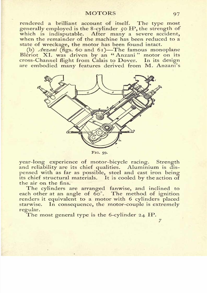
8/6/2019 1910 howtobuildaeropl00petirich
http://slidepdf.com/reader/full/1910-howtobuildaeropl00petirich 117/150
MOTORS 97
rendered a brilliant account of itself. The type most
generally employed is the 8-cylinder 50 EP, the strength of
which is indisputable. After many a severe accident,
when the remainder of the machine has been reduced to a
state of wreckage, the motor has been found intact.
(b) Anzani(figs.
60 and 61) The famous monoplaneBleriot XL was driven by an " Anzani
"motor on its
cross-Channelflight
from Calais to Dover. In its designare embodied many features derived from M. Anzani's
FIG. 59.
year-long experience of motor-bicycle racing. Strengthand
reliabilityare its chief
qualities.Aluminium is dis-
pensed with as far as possible, steel and cast iron beingits chief structural materials. It is cooled by the action of
the air on the fins.
The cylinders are arranged fanwise, and inclined to
each other at an angle of 60. The method ofignition
renders it equivalent to a motor with 6cylinders placed
starwise. In consequence, the motor-couple is extremely
regular.
The most general type is the 6-cylinder 24 IP.
7

8/6/2019 1910 howtobuildaeropl00petirich
http://slidepdf.com/reader/full/1910-howtobuildaeropl00petirich 118/150
98 HOW TO BUILD AN AEROPLANE
FIG. 60.
FIG. 61.

8/6/2019 1910 howtobuildaeropl00petirich
http://slidepdf.com/reader/full/1910-howtobuildaeropl00petirich 119/150
MOTORS 99
(c)Esnault-Pelterie
(figs.62 and 63) The " R.E.P."
is perhaps the most carefully designed ofexisting light
motors.
The composition is remarkable from every point of
view. Starting with the simple laws of the structural
strength of various materials, and drawing upon his wide
FIG. 62.
knowledge of the most recent developments ofmetallurgy,
Esnault-Pelterie has succeeded in producing a motor which
gives a maximum IP with a minimum weight. The
strength of materials never exceeds a certain value;hither-
to this strength has only been called upon to furnish the
highest possible result during a very small fraction of
time. Esnault-Pelterie has started from theprinciple of
lengthening the duration of the maximum effort, and
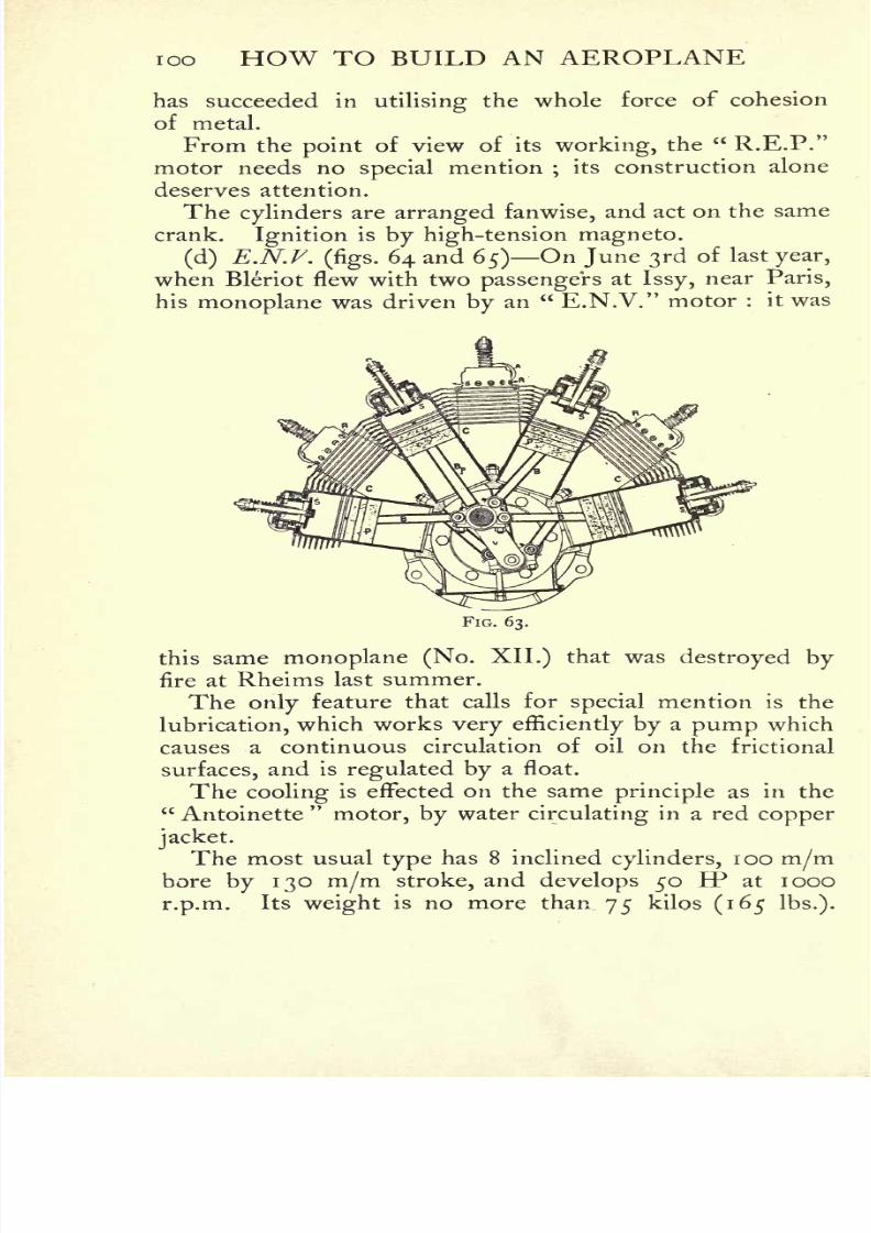
8/6/2019 1910 howtobuildaeropl00petirich
http://slidepdf.com/reader/full/1910-howtobuildaeropl00petirich 120/150
ioo HOW TO BUILD AN AEROPLANE
has succeeded in utilisingthe whole force of cohesion
of metal.
From the point of view of its working, the" R.E.P."
motor needs no special mention ;its construction alone
deserves attention.
The cylinders are arranged fanwise, and act on the same
crank. Ignition is by high-tension magneto.
(d) E.N.F.(figs. 64 and 65) On June 3rd of last year,
when Bleriot flew with two passengers at Issy,near Paris,
his monoplane was driven by an" E.N.V." motor : it was
FIG. 63.
this same monoplane (No. XII.)that was
destroyed byfire at Rheims last summer.
The only feature that calls for special mention is the
lubrication, which works very efficiently by a pump which
causes a continuous circulation of oil on the frictional
surfaces, and is regulated by a float.
The cooling is effected on the sameprinciple as in the
" Antoinette"motor, by water circulating in a red copper
jacket.
The most usual type has 8 inclined cylinders, ioo m/mbore by 130 m/m stroke, and develops 50 IP at 1000
r.p.m. Its weight is no more than 75 kilos (165 Ibs.).
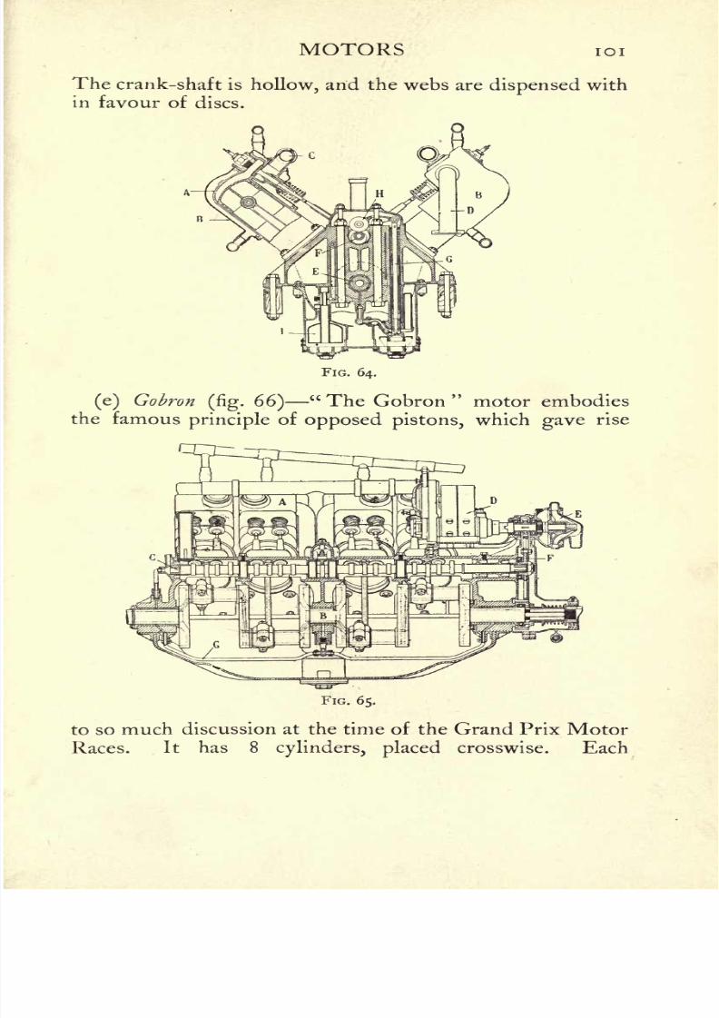
8/6/2019 1910 howtobuildaeropl00petirich
http://slidepdf.com/reader/full/1910-howtobuildaeropl00petirich 121/150
MOTORS 101
The crank-shaft is hollow, and the webs are dispensed with
in favour of discs.
FIG. 64.
(e) Gobron(fig.
66)
" The Gobron"motor embodies
the famousprinciple of opposed pistons, which gave rise
FIG. 65.
to so much discussion at the time of the Grand Prix Motor
Races. It has 8 cylinders, placed crosswise. Each

8/6/2019 1910 howtobuildaeropl00petirich
http://slidepdf.com/reader/full/1910-howtobuildaeropl00petirich 122/150
102 HOW TO BUILD AN AEROPLANE
cylinder contains a pair of pistons working in opposite
directions.
The motor develops 80 BP and weighs 1 50 kilos. Its
fuel consumption is no more than 35 cubic centimetres
per IP-hour. It has been used on the Breguet and
Gobron aeroplanes.
(f)Duthtil and Chalmers
(fig. 67) On M. Santos-
Dumont's miniature monoplane it has given proof of ex-
cellentqualities.
It is noteworthy by reason of the small
space it occupies and the simple manner in which it can
be mounted on an aeroplane. The cylinders are
horizontal and opposed. A point to be noticed is the
excellent hemispherical combustion-chamber, which is
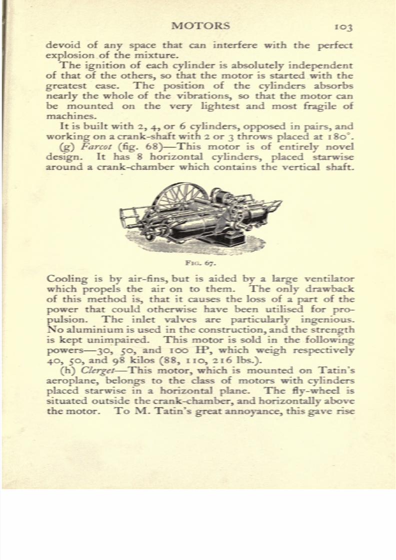
8/6/2019 1910 howtobuildaeropl00petirich
http://slidepdf.com/reader/full/1910-howtobuildaeropl00petirich 123/150
MOTORS 103
devoid of any space that can interfere with the perfect
explosion of the mixture.
The ignition of each cylinder is absolutely independent
of that of the others, so that the motor is started with the
greatest ease. The position of the cylinders absorbs
nearly the whole of the vibrations, so that the motor can
be mounted on the very lightest and mostfragile
of
machines.
It is built with 2, 4, or 6 cylinders, opposed inpairs,
and
working on a crank-shaft with 2 or 3 throws placed at 1 80*.
(g)Farcot
(fig. 68)This motor is of
entirelynovel
design. It has 8 horizontal cylinders, placed starwise
around a crank-chamber which contains the vertical shaft.
Cooling is by air-fins, but is aided by a large ventilator
which propels the air on to them. The only drawback
of this method is, that it causes the loss of a part of thepower that could otherwise have been uliKsfd for pro-
pulsion. The inlet valves are particularly ingenious.
No aluminium is used in the construction, and the strengthis kept unimpaired. This motor is sold in die following
puwcis 30, 50, and 100 HP, which weigh respectively
40, 50, and 98 kilos (88, no, 216Ibs.).
(h) Clerget This motor, which is mounted on Tatin's
aeroplane, belongs to the class of motors with cylinders
placed starwise in a horizontal plane. The fly-wheel is
situated outside the crank-chamber, and horizontally above
the motor. To M. Tatin's great annoyance, this gave rise
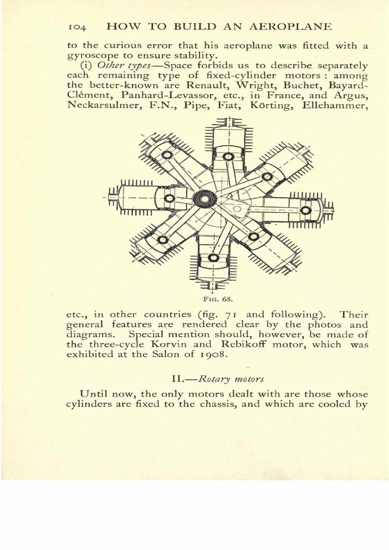
8/6/2019 1910 howtobuildaeropl00petirich
http://slidepdf.com/reader/full/1910-howtobuildaeropl00petirich 124/150
io4 HOW TO BUILD AN AEROPLANE
to the curious error that his aeroplane was fitted with a
gyroscope to ensurestability.
(i)Other types Space forbids us to describe
separately
each remaining type of fixed-cylinder motors : amongthe better-known are Renault, Wright, Buchet, Bayard-
Clement, Panhard-Levassor, etc., in France, and Argus,
Neckarsulmer, F.N., Pipe, Fiat, Korting, Ellehammer,
FIG. 68.
etc., in other countries(fig. 71 and following). Their
general features are rendered clear by the photos and
diagrams. Special mention should, however, be made of
the three-cycle Korvin and Rebikoff motor, which was
exhibited at the Salon of 1908.
II. Rotary motors
Until now, the only motors dealt with are those whose
cylinders are fixed to the chassis, and which are cooled by
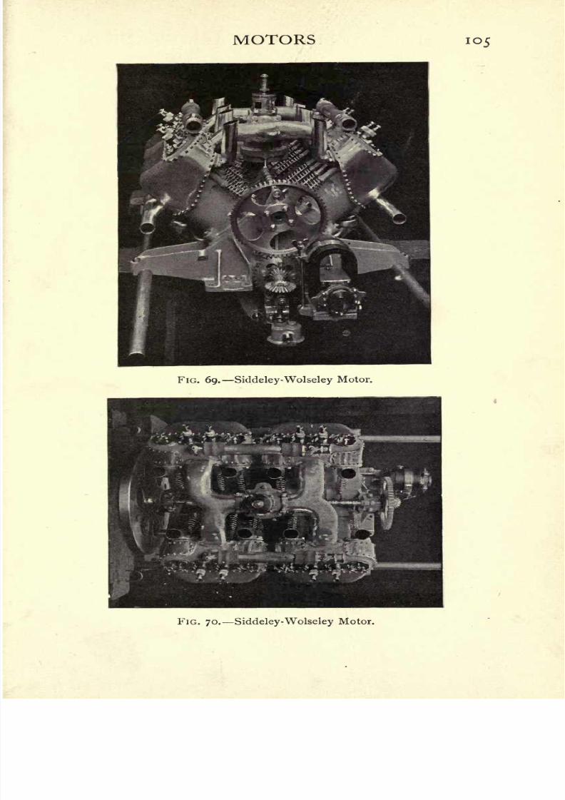
8/6/2019 1910 howtobuildaeropl00petirich
http://slidepdf.com/reader/full/1910-howtobuildaeropl00petirich 125/150
MOTORS 105
FIG. 69. Siddeley-Wolseley Motor.
FIG. 70. Siddeley-Wolseley Motor.
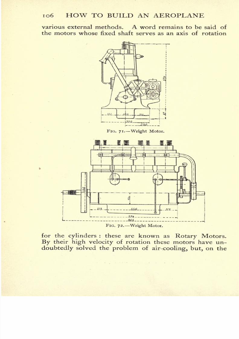
8/6/2019 1910 howtobuildaeropl00petirich
http://slidepdf.com/reader/full/1910-howtobuildaeropl00petirich 126/150
io6 HOW TO BUILD AN AEROPLANE
various external methods. A word remains to be said of
the motors whose fixed shaft serves as an axis of rotation
FIG. 71. Wright Motor.
FIG. 72. Wright Motor.
for the cylinders : these are known as Rotary Motors.
By their high velocity of rotation these motors have un-
doubtedly solved the problem ofair-cooling, but, on the

8/6/2019 1910 howtobuildaeropl00petirich
http://slidepdf.com/reader/full/1910-howtobuildaeropl00petirich 127/150
MOTORS 107
\.J*
FIG. 73. Wright Motor.
FIG. 74. Pipe Motor.
FIG. 75-
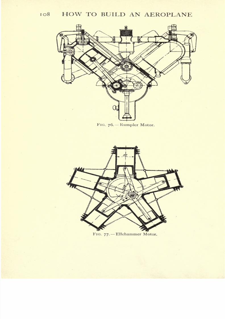
8/6/2019 1910 howtobuildaeropl00petirich
http://slidepdf.com/reader/full/1910-howtobuildaeropl00petirich 128/150
io8 HOW TO BUILD AN AEROPLANE
FlG. 76. Rumpler Motor.
YIG. 77. Ellehammer Motor.

8/6/2019 1910 howtobuildaeropl00petirich
http://slidepdf.com/reader/full/1910-howtobuildaeropl00petirich 129/150
MOTORS 109
other hand, it is evident that in their case the feeding of
thepetrol into the cylinders and the ignition
are points of
much complexity. Satisfactory rotary motors, as a matter
FIG. 78.
of fact, have not existed until the last few months, for
previous engines of this type, such as the"Burlat," only
pointed the way to success. The great Rheims Aviation
Week last year first demonstrated that therotary motor
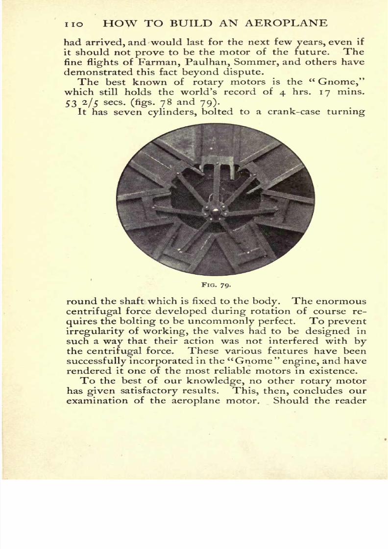
8/6/2019 1910 howtobuildaeropl00petirich
http://slidepdf.com/reader/full/1910-howtobuildaeropl00petirich 130/150
no HOW TO BUILD AN AEROPLANE
had arrived, and would last for the next few years, even if
it should not prove to be the motor of the future. The
fineflights
of Farman, Paulhan, Sommer, and others have
demonstrated this fact beyond dispute.The best known of rotary
motors is the"Gnome,"
which still holds the world's record of 4 hrs. 17 mins.
53 2/5 sees.(figs. 78 and 79).
It has seven cylinders,bolted to a crank-case turning
FIG. 79.
round the shaft which is fixed to the body. The enormous
centrifugal force developed during rotation of course re-
quiresthe bolting to be uncommonly perfect. To prevent
irregularityof working, the valves had to be designed in
such a way that their action was not interfered with bythe centrifugal force. These various features have been
successfully incorporated in the "Gnome" engine, and have
rendered it one of the most reliable motors in existence.
To the best of our knowledge, no other rotary motor
has given satisfactory results. This, then, concludes our
examination of the aeroplane motor. Should the reader

8/6/2019 1910 howtobuildaeropl00petirich
http://slidepdf.com/reader/full/1910-howtobuildaeropl00petirich 131/150
8/6/2019 1910 howtobuildaeropl00petirich
http://slidepdf.com/reader/full/1910-howtobuildaeropl00petirich 132/150
CHAPTER VIII
THE FUTURE
THE chief aim of this book has been to give the general
public a thorough understanding of the true nature and
possibilitiesof mechanical
flight,but this aim cannot be
realised unless we glance brieflyat the radiant future that
stretches before it.
Born as it was but a few years ago, aviation has not
yet attained a sufficiently advanced stageof development
to allow every member of the public to grasp its enor-
mous futureinfluence on
commerce, sport, andwarfare.
Although the time may still be far removed when we
shall witness the passage of some aerial liner plying
between Paris and Tokio, in a short while a few months
we shall see the sportsman and the tourist winging their
flightover the countryside ; for, with Lilienthal, they are
"seized with the vague longing to glide along noiselessly
in a majestic flight, high above the green forests and blue
waters." 1 Aviation has made this dream come true.
Even though the aeroplane should possess no purely
commercial future, it is certain that touring aeroplanes
will be manufactured in large quantitiesfor many years
to come. Before very long the motor car of the air will
have become common, and largely patronised on account
of its speed and unique qualities.
Aviation will develop, as the motor car did a few years
ago, with astonishing rapidity. Before ten years have
elapsed the laws and regulations of the air will have
1 Otto Lilienthal, Der Vogelflug als Grundlage der Fliegekunst.
112
8/6/2019 1910 howtobuildaeropl00petirich
http://slidepdf.com/reader/full/1910-howtobuildaeropl00petirich 133/150
THE FUTURE 113
passed into the daily life of the community ;the aeroplane
will be as common as a bicycle to-day ;its low price
due to the fact that the motive power will gradually be
decreased will bring it within the reach of everyone.
Is itlikely
that the dream of many inventors will ever
be realised, that the aerial bicycle, cycloplane, aerocycle, or
whatever it may be called, will ever become a fact ? Wecannot believe it, although it would be unwise to make a
dogmatic assertion on the point.
Reliable experiments have proved that the muscular
power of a man is hopelessly insufficient to raise the
necessary weight. No doubt, in future, flightwill be
possible with very low-powered motors (3 EP or evenless),
but we firmly believe that the irreducible minimum must
be fixed at 105 kilogrammetre-seconds, that is,2 IP.
Of late years many discussions, which for the greater
part have reached no definite result, have raged round the
question of what form of machine will eventually survive.
Strange tosay,
the very success of the aeroplane has
brought forth a class of inventors who cling desperately
to their pet ideas in the face of all evidence. When will
the"ornithopterists," the
"entomopterists," and the
other visionaries, whose names indicate the creature whose
method offlight they seek to imitate, understand that the
aeroplane forms the only economical solution of the
problem of aerial navigation ?
The screw-propeller, according to them, is a device
which wastes the power transmitted to it by the motor.
But this argument isutterly false, and need not be
refuted. Then, in addition to their onslaught on the
screw-propeller, they assiduously seek to prove that the
aeroplane glides on the air, but does notfly.
Whatmatters the precise way in which it is sustained so longas this is economical and duly safe ? Side-winds and
eddies are already overcome with ease by new devices,
and thestability
of the aeroplane is every day increased.
Theflights
of Farman, Latham, and Paulhan have
8
8/6/2019 1910 howtobuildaeropl00petirich
http://slidepdf.com/reader/full/1910-howtobuildaeropl00petirich 134/150
n 4 HOW TO BUILD AN AEROPLANE
adequately proved the security andefficiency
of "the
plane gliding on the air," which is not likely to be sur-
passed by any system of"beating, rotating,
or gyrating
wings." What is the object of these contrivances, whichare based on complete ignorance of the laws of mechanics ?
Their inanity would be obvious enough if their inventors
would only embody them in a working model. We are
ready to be converted to thepracticability of any system
in the same way in which we converted those who scoffed
at the aeroplane by actualflight.
As a matter of fact,
the
alternating
mechanism of the
wings
would absorb
four-fifths of the motive power, which, therefore, would
be insufficient to procure sustentation. The hopeless im-
practicabilityof the beating-wing machine could be proved
by many other excellent reasons, which, however, are too
long to set down here, andsufficiently obvious to every
sensible mind.
The aeroplane, then, is the one practical aerial machine.
Nor is it difficult to decide between the respective claims
of the biplane and monoplane. From the mechanical
point of view the monoplane possesses greater efficiency:
instability
it can be made the equal of the biplane, nor
has it any greater difficulties of construction. The mono-
plane alone will survive;
its high speed will render it
indifferent to all atmospheric disturbances;
itsstability,
therefore,
will beperfect. Eventually
the
monoplanewill be able to attain enormous speeds up to 150 and
200 miles an hour; every point on the surface of the
earth will be brought within reach;communication will
be rapid and constant;frontiers will disappear ;
and the
nations will have approached within measurable distance
of Utopia and international peace.
8/6/2019 1910 howtobuildaeropl00petirich
http://slidepdf.com/reader/full/1910-howtobuildaeropl00petirich 135/150

8/6/2019 1910 howtobuildaeropl00petirich
http://slidepdf.com/reader/full/1910-howtobuildaeropl00petirich 136/150
n6 HOW TO BUILD AN AEROPLANE
drilled out. Passing through the holes thus formed are
bolts which serve to tie together the cylinders mounted
on the crank-chamber and the crank-shaft bearings.
The magneto and the water circulating pump are
placed in the same line and immediately in front of the
crank-case at right angles with the crank-shaft, both beingdriven by worm wheels direct from the crank-shaft.
The general lubrication of the engineis effected in an
entirely novel manner, as simple as it is efficient.
FIG. 80.
Running the entire length of the interior of the crank-
case on one side, near the top, is the main oil channel
cast solid with the crank-case, through which oil is forced
by a small gear pump through leads at right angles
communicating directlyto each of the hollow columns
through which the bolts pass, and thence to the main
bearings and crank-shaft, which is hollow. The reduction
of the diameter of the central portion of the bolts allows
of sufficient room for the free flow of oil to the main
bearings,from which it
passes into the hollow crank-shaft,
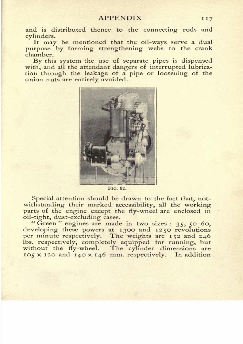
8/6/2019 1910 howtobuildaeropl00petirich
http://slidepdf.com/reader/full/1910-howtobuildaeropl00petirich 137/150
APPENDIX 117
and is distributed thence to the connecting rods and
cylinders.
It
may
be mentioned that the oil-ways serve a dual
purpose by forming strengthening webs to the crank
chamber.
By this system the use of separate pipesis dispensed
with, and all the attendant dangers of interrupted lubrica-
tion through the leakage of a pipe or loosening of the
union nuts are entirely avoided.
FIG. 8 1.
Special attention should be drawn to the fact that, not-
withstanding their markedaccessibility,
all the working
parts of the engine except the fly-wheel are enclosed in
oil-tight, dust-excluding cases.
"Green" engines are made in two sizes : 35, 5060,
developingthese
powersat
1300and
1250revolutions
per minuterespectively. The weights are 152 and 246
Ibs.respectively, completely equipped for running, but
without the fly-wheel. The cylinder dimensions are
105 x 1 20 and I4OX 146 mm.respectively.
In addition

8/6/2019 1910 howtobuildaeropl00petirich
http://slidepdf.com/reader/full/1910-howtobuildaeropl00petirich 138/150
n8 HOW TO BUILD AN AEROPLANE
an 80-100 P engine is manufactured which has eight
cylinders, arranged in V formation.
The feature of these engines is their remarkable relia-
bility and evenness of running. Mr Moore-Brabazon
FIG. 82.
used a 50-60" Green
"engine on his circular mile
flight,
which won the 1000 Daily Mailprize on 28th October
1909. A 35 HP engine is fitted to the Army dirigible
Baby, while the new military dirigible is fitted with an 80-100 EP " Green
"motor.
PRINTED BY NEILL AND CO., LTD., EDINBURGH.
8/6/2019 1910 howtobuildaeropl00petirich
http://slidepdf.com/reader/full/1910-howtobuildaeropl00petirich 139/150
GREEN'SBRITISH BUILT AERIAL
ENGINEGreen's Patent Aerial Engine represents Years ofLabour devoted to the designing and construction of an
Engine which, while reduced to the closest possible
limit in weight, shall be Absolutely Efficient under the
varying conditions encountered in Aerial Navigation.
Every Detail has had the Most Minute Attention.
The Weight has beenScientifically Reduced without
any cutting down of bearing surfaces or wearing parts.
The Highest Efficiencyis Maintained at All Speeds,
andduring
ContinuousRunning
under Full Load.
Green's Engine has been adopted by H.M. Wai-
Office, and was used in the successful Trial for the
1000 Daily Mai! Prize.
GREEN'S MOTOR PATENTS SYNDICATE, LID.
55 BERNERS STREET, LONDON, W.
Makers for the Patentees
The Aster Engineering Company, Limited.
119

8/6/2019 1910 howtobuildaeropl00petirich
http://slidepdf.com/reader/full/1910-howtobuildaeropl00petirich 140/150
J.BONN & CO. LTD.
97 NEW OXFORD STREET
LONDON, W.C
Inventors :: Model Makers
INVENTIONS DEVELOPED AND CARRIED OUT UNDER
STRICT SECRECY
Aero Inventions a Speciality
SOCKETS, LUGS, BRACKETS, WIRE STRAINERS,
BAMBOO, SPRUCE, ASH, CANE, MAGNALIUM TUBING,
SHEET ALUMINIUM, AND ALL MATERIALS APPER-
TAINING TO AERONAUTICS KEPT IN STOCK ORMADE TO ORDER
Type No. i, Biplane Cambered Aerofoils, mono-
plane tail with vertical vanes. Price, complete,
according to finish, from 15. If built collapsible,
price from 17. Types Nos. 2 and 3, double-
ribbed aerofoils, double surfaced with waterprooffabric front control, price from 25 and 65 respectively ; may be had with detach-
able ends to main planes at 3 and 7 extra.
AEROPLANESType No. i, 20 horse-power biplane, front elevator, lever control, complete with British
rotary engine, detachable ends to planes, . . Price, according to finish, from 25OType No. 2, 30 horse-power, with rotary engine ,, ,, ,, 42O
,, 3, 40 ,, ,, ,, (for passenger) ,, ,, ,, 555Aeroplane fittings, wheels, fabric, wire strainers, engines, propellers, and all accessories.
Monoplanes, 4/6, 7/6, and 12/6. Biplanes, 7/6,
21/-,3 3/-, 7 7/-, and 12 12/-. All
British made. Parcels of materials for buildingfrom I/- up to 15/6.
MODELSFine Art Aeroplane Catalogue, second edition, with a working drawingfor
building a model Biplane, 4d. postfree.
THE TWINING AEROPLANE CO.Offices and Workshops :
29b GROSVENOR ROAD, HANWELL, MIDDLESEX
120
8/6/2019 1910 howtobuildaeropl00petirich
http://slidepdf.com/reader/full/1910-howtobuildaeropl00petirich 141/150
T. W. K. CLARKE & GO.AERONAUTICAL ENGINEERS
CROWN WORKS, HIGH STREET,KINGSTON-ON-THAMES.
GLIDERS from 40.
AEROPLANES complete
from 38O.
SPECIALITY : Built-up
"CLARKE" PROPELLORS
Exact SCALE MODELS of all standard
machines.
Contractors to H.M. GOVERNMENT.ALL MODEL MAKING requisites.
Send for LISTS.
Telegrams"
Flyers," Kingston-on -Thames.
Telephone 1183, P.O. Kingston. 100 IP "CLARKE" Propeller
HARTS PROOFEDAERO FABRICSFor Balloons, Airships, Gas-Bags, Aeroplanes,
Gliders, and Models
From I oz. the square yard in weight.
Water-proof
Air-proof
Gas-tight
Light in Weight
Moderate in Price
In any Colour
Contain no Rubber
Made in England
Various Materials
These original materials have stood the severest tests for Waterproof-
ness and Gas-tightness, and one has been selected for use in the construc-
tion of the great Naval Dirigible.
WRITE FOR SAMPLES AND INFORMATION TO
HARTS, 21 Liverpool Street, London, E.G.
121
8/6/2019 1910 howtobuildaeropl00petirich
http://slidepdf.com/reader/full/1910-howtobuildaeropl00petirich 142/150
TELEGRAPHIC ADDRESS: "KRANKASES," LONDON.
-- relefihoi,
N4879 CENTRAL
LARGE & SMALLIN fUJRE 5t HARDENED
FOR ALL TRADES.HAM IN fUftE St. HARDENED
>?A FOR ALL TRADES.w* WMii^Mi^^g*; a/VJE OF THE PIQN&ELR& OF
(RANK AL.UMINIUM. cAsr/^/cs*'-'^FS 2I9r COSWELL ROAD,
Afl^^ ! i X M rt s* itf c- rL.ONDOM, E.G.
ALSO IRON CYLINDERS REPAIRED. ON WAR OFFICE AND ADMIRALTY LIS1
THE
AERONAUTICAL JOURNALEditedfor the Council of the Aeronautical Society of Great Britain by
T. O'B. HUBBARD and}. H. LEDEBOER
An Illustrated Quarterlydevoted to the Science of Dynamic
Flight in all its Branches
ANNUAL SUBSCRIPTION, 6/6 Post Free.
THE AERONAUTICAL SOCIETY OF GREAT BRITAIN
53 Victoria Street, Westminster, London, S.W.
Telephone: 3656 Victoria
122
8/6/2019 1910 howtobuildaeropl00petirich
http://slidepdf.com/reader/full/1910-howtobuildaeropl00petirich 143/150
Books on Aeronautics
AIRSHIPS, PAST AND PRESENT. Together with chapters on the
use of balloons in connection withmeteorology, photography,and the carrier pigeon. By A. HILDEBRANDT, Captain and Instructor
in the Prussian Balloon Corps. Translated by W. H. Story. 8vo., cloth, 361 pp.,
222 illustrations $3.50 net
CONTENTS: Early History of the Art. Invention of the Air Balloon. Montgolfieres,
Charlieres, and Rozieres. Theory of the Balloon. Development of the Dirigible Bal-
loon. History of the Dirigible Balloon, 1862-1872. Dirigible Balloons from 1883-1897;
1898-1906. Flying Machines. Kites. Parachutes. Development of Military Ballooning,
Ballooning in Franco-Prussian War. Modern Organization of Military Ballooning in
France, Germany, England and Russia. Military Ballooning in Other Countries. Balloon
Construction and the Preparation of the Gas. Instruments, Ballooning as a Sport,
Scientific Ballooning. Balloon Photography. Photographic Outfit for Balloon Work.
Interpretation of Photographs. Hectography by Means of Kites and Rockets. Carrier
Pigeons for Balloons. Balloon Law.
AERIAL FLIGHT. Vol. 1. Aerodynamics. By F. W. LANCHESTER.
8vo., cloth, 438 pp., illustraetd $6.00 net
CONTENTS : Fluid Resistance and Its Associated Phenomena. Viscosity and Skin
Friction. The Hydrodynamics of Analytical Theory. Wing Form and Motion in the
Peritery. The Aeroplane. The Normal Plane. The Inclined Aeroplane. The
Economics of Flight. The Aerofoil. On Propulsion, the Screw Propeller, and the
Power Expended in Flight. Experimental Aerodynamics. Glossary, Appendices,
AERIAL FLIGHT. Vol. II. Aerodonetics. By F. W. LANCHESTER,
8vo., cloth, 433 pp., 208 illustrations $6.00 net
CONTENTS: Free Flight, General Principles and Phenomena. The Phugoid
Theory The Equations of the Flight Path. The Phugoid 1852-1872, Dirigible
Balloons from 18831897; 1898-1906. Flying Machine Theory The Flight Path
Plotted. Elementary Deductions from the Phugoid Theory. Stability of the Flight
Path as Affected by Resistance and Moment of Inertia. Experimental Evidence
and Verification of the Phugoid Theory. Lateral and Directional Stability, Review of
ChaptersI to
VII,and General Conclusions
Soaring. Experimental.Aerodonetics,
AERIAL NAVIGATION. A practical handbook on the construction
of dirigible balloons, aerostats, aeroplanes and aeromotors, by
FREDERICK WALKER. Second Edition, thoroughly revised and enlarged.
12mo., cloth, 175 pp., 128 illustrations $2.00 net
CONTENTS : Laws of Flight. Aerostatics. Aerodynamics. Aeroplanes in Practice,
Motive Power. Screw Propulsion for Aeroplanes and Airships. Airships and
Dirigible Aerostats. Construction. Aeroplanes and Airships in Use. Supplement
Describing Distinctive Successful Types.
HOW TO DESIGN AN AEROPLANE. By HERBERT CHATLEY.
16mo., boards, 109 pp., illustrated (Van Nostrand's Science Series). . . .50 cents
CONTENTS: The Aeroplane. Air Pressure. Weight. Propellers and Motors.
Balancing. Construction. Difficulties. Future Developments, Cost. Other Flying.
Machines (Gyroplane and Orinthoptere).
D. Van Nostrand Company
8/6/2019 1910 howtobuildaeropl00petirich
http://slidepdf.com/reader/full/1910-howtobuildaeropl00petirich 144/150
8/6/2019 1910 howtobuildaeropl00petirich
http://slidepdf.com/reader/full/1910-howtobuildaeropl00petirich 145/150
8/6/2019 1910 howtobuildaeropl00petirich
http://slidepdf.com/reader/full/1910-howtobuildaeropl00petirich 146/150

8/6/2019 1910 howtobuildaeropl00petirich
http://slidepdf.com/reader/full/1910-howtobuildaeropl00petirich 147/150
8/6/2019 1910 howtobuildaeropl00petirich
http://slidepdf.com/reader/full/1910-howtobuildaeropl00petirich 148/150
BOOK. IS TJtiJti VA.TESTAMPED BELOW
AN INITIAL FINE OF 25 CENTSWILL BE ASSESSED FOR FAILURE TO RETURNTHIS BOOK ON THE DATE DUE. THE PENALTYWILL INCREASE TO 5O CENTS ON THE FOURTHDAY AND TO $1.OO ON THE SEVENTH DAYOVERDUE.
fB 14 1935
V''
APR %& 1948
:EC'D ***
^17196928
8/6/2019 1910 howtobuildaeropl00petirich
http://slidepdf.com/reader/full/1910-howtobuildaeropl00petirich 149/150
[ T TO Iv7
^M/
*
;
\

8/6/2019 1910 howtobuildaeropl00petirich
http://slidepdf.com/reader/full/1910-howtobuildaeropl00petirich 150/150