1914 - popular mechanics's how to make a wireless set
TRANSCRIPT


HOW TO MAKE A
WIRELESS SETBY
ARTHUR MOORE
POPULAR MECHANICS HANDBOOKS
CHICAGOPOPULAR MECHANICS CO
Copyright, 1911,
by H. H. WINDSOR

THISbook is one of the series of
handbooks on industrial subjects
being published by the PopularMechanics Company. Like the
Magazine, these books are "written
so you can understand it," and are
intended to furnish information on
mechanical subjects at a price within
the reach of all.
The text and illustrations have
been prepared expressly for this
Handbook Series, by experts; are
up-to-date, and have been revised bythe editor of Popular Mechanics.


CONTENTS
PAGE
Chapter I The Necessary Parts 9
Chapter II The Spark Coil 15
Chapter III The Condenser 22
Chapter IV The Spark Gap and Vibrator 29
Chapter V Construction of Telegraph Key and
Aerial Wires 37
Chapter VI Construction of a Coherer and a
Decoherer 43
Chapter VII Construction of a Potentiometer ... 51
Chapter VIII Secondary Windings 59
Chapter IX Another Secondary Winding 67
Chapter X Connections for Sets 77


HOW TO MAKE A
WIRELESS SETCHAPTER I
THE NECESSARY PARTS
THERE is no field of electrical experimentationthat has received more attention from the ama-
teur in the last few years than that of wireless teleg-
raphy. A great many persons have the impressionthat one must be an electrical engineer in order to con-
struct and operate successfully a wireless telegraphset. Such an impression is not well grounded. Thefollowing description of a small wireless set will not
only be useful to those who wish to experiment alongthis particular line, but it will be a great aid in makingclear the elementary principles upon which wireless
telegraphy is based. A set suitable for transmittingfor distances of four or five miles in the open countrycan be easily constructed by a boy of ordinary abil-
ity at a small cost. The information gained by con-
structing a small set would be a great help to those
who intend building larger outfits later.
Before explaining the construction of the various
parts in detail, it might "be well to give a general de-
scription of them and explain their functions and ope-ration. You will need the following parts to completethe equipment for a single station that can both sendand receive a message : A spark coil that is capable of
producing a spark from 1 to 1^/2 in. long, telegraph


HOW TO MAKE A WIRELESS SET 11
key, 150 or 200-ohm relay, common vibrating electric
bell, aerial conductors, coherer and spark gap.The spark coil is used to produce a very high voltage
current from a source of electrical energy of low volt-
age, such as dry cells, and consists of two windingsabout an iron core.
The source of electrical energy is connected in series
with one of these windings, which is called the "pri-
mary."' The terminals of the other winding are con-
nected to the spark gap, as shown in Fig. 1. This sec-
ond winding is called the "secondary." There will
be produced in the secondary winding an electromo-
tive force when there is a change of current in the pri-
mary. If the primary circuit is then made and broken
by placing the telegraph key in circuit with it, there
will be an electromotive force set up in the secondaryfor each make and break in the primary due to the
operation of the key. The value of the induced elec-
tromotive force in the secondary will depend uponthe ratio of primary and secondary turns and the ra-
pidity of the "making and breaking" of the primarycircuit which can be greatly increased by placing in
the circuit a current "breaker," or interrupter, as it is
more usually termed. The construction of the inter-
rupter is indicated in Fig. 1. When the key K is
closed, the iron core l l becomes magnetized, due to
the current in the primary, and as a result attracts the
iron armature I, which is normally held away fromthe core by the spring G. The movement of the ar-
mature I toward the core I lf results in the contact at
C being broken and the current in the primary wind-
ing dropping to zero. The iron core loses its magnet-ism and the armature again returns to its normal po-sition, completing the circuit at C and again goingthrough the same operation. With this interrupter in

12 HOW TO MAKE A WIRELESS SET
circuit, as shown in Fig. 1, there will be a number of
makes and breaks in the primary when the key is
closed only for a short time and hence a much greaterelectromotive force set up in the secondary.There is quite an arc formed at the contact C when
the circuit is broken, due to the inductance of the pri-
mary winding. The condenser D is connected directlyacross the gap and reduces to a great extent the ten-
dency for the arc to form, and as a result, the decay of
the primary current is a great deal more rapid, hencea greater electromotive force is set up in the second-
ary, and it will be continuous as long as the key is
closed.
One terminal of the spark gap is well grounded andthe other terminal is connected to the aerial as indi-
cated in Fig. 1. The aerial may be made from a
piece of Xo. 14 gauge copper wire that has one endfastened to the top of a GO or 70-ft. pole by means of
two knob insulators. One of these knobs can be tied
to a rope that runs in a small pulley on the top of the
pole ; one end of the aerial is fastened to the other in-
sulator or knob, and the two knobs are then connected
by a link of wire. The aerial should be run off at an
angle to the pole to prevent them touching, and it
should be well insulated where it is led into the build-
ing. If it is possible, the pole carrying the aerial
should be placed on the top of a building. This will
give much better results. A good ground connectioncan be made by soldering a No. 14 gauge wire to a
metal plate and burying it at a depth of 5 or G ft. in
moist earth. The sending end is now complete. Thedetails in construction and adjustment will be taken
up later.
The coherer is the most important part of the re-
ceiving set. Branly was the first to discover that a
HOW TO MAKE A WIRELESS SET 13
quantity of iron filings when brought within the in-
fluence of a high-frequency discharge, such as that
from an induction coil or Leyden jar, will cling to-
gether, or cohere as it is termed, thus lowering the re-
sistance of the quantity of iron filings as a whole, anda current from a battery will more easily flow throughthem when they are in coherence than when they are
not. These filings are usually placed in a glass tubebetween two metal terminals. One of these terminals
is connected to the aerial and the other is grounded,when the station is used in receiving, as in Fig. 2.
A battery of low voltage and the relay are con-
nected across the terminals of the coherer, as shown in
Fig. 2. The adjustment of the coherer and the relayis such that there is not sufficient current through the
relay to operate it when the filings are not cohered.
When, however, the coherer is acted upon by a high-
frequency discharge, the filings will cohere, thus re-
ducing the resistance of the relay circuit and increas-
ing the current through the relay, which will operateit, if the proper adjustment has been made.This relay in Fig. 2 can be made to close a second
local circuit consisting of a battery of a few dry cells
and an ordinary vibrating bell, which serves to givean audible signal. The relay consists of two magnetcoils connected in series and their outside terminalsconnected to the posts P! and P 2 , Fig. 2. There is a
soft iron armature that is delicately balanced on twopivots near the ends of the cores of these two coils.
These two iron cores become sufficiently magnetized,due to a very small current in the coils, to attract the
armature, which is normally held away from them a
very small distance by a weak coil spring. The arma-ture closes the second circuit by coming in contactwith the point P
3 .

14 HOW TO MAKE A WIRELESS SET
When the iron filings are once cohered they will
not return to their original condition if they are re-
moved from the influence of the high-frequency dis-
charge, and as a result the bell would continue to
ring even though the coherer was not being acted
upon by any discharge. To overcome this objection-able feature the filings must be decohered, which canbe done by allowing the tapper of the electric bell to
strike lightly against the glass tube of the coherer.
The receiving station is now complete and the opera-tion of such a set can be traced as follows : The tele-
graph key at the sending end is pressed, allowing a
current to flow through the primary winding andstart the vibrator in operation. At each make andbreak of the primary circuit due to the vibrator, there
will be a high voltage induced in the secondary whichis sufficient to break down the air gap between the ter-
minals of the spark gap, and as a result, a high-fre-
quency current will flow in the secondary circuit.
This high-frequency current oscillates up and downthe aerial and is supposed to set up a similar motionin the ether existing in the air and the ground. This
wave motion is sent out in all directions and any re-
ceiving station that is within its influence receives a
small portion of the total energy sent out. As a re-
sult a very high frequency current flows through the
coherer, thus reducing its resistance and operating the
relay and closing the local circuit which starts the
bell in operation. The bell will continue to ring as
long as the wave continues to come in, which is de-
termined by the time the telegraph key at the sendingend is closed, and as a result the dots and dashes of
the code can be easily distinguished.

CHAPTER II
THE SPARK COIL
THE spark coil is the principal piece of apparatusused in the transmitter of a wireless telegraph set
and its detailed construction is given herewith. Thecoil described here can be used for ordinary laboratorywork, lighting Geissler tubes, etc., in addition to its
use in the wireless set. All spark coils might be
thought of as composed of the following parts: iron
wire core,' primary winding, secondary winding, vi-
brator, condenser and containing case. These vari-
ous parts will be taken up in turn.
The core of a spark coil is one of the most impor-tant parts and it should be constructed of a large num-ber of small soft iron wires. If a solid iron core is
used, the reversal of magnetism in the core does nottake place as rapidly as the current is interrupted bythe vibrator. That is, the solid iron core would not
take on and lose its magnetic effect as rapidly as the
vibrator worked, which would result in a weak cur-
rent in the secondary. A core composed of a numberof small iron wires is said to be laminated.To build the core, procure a sufficient quantity of
No. 22 gauge soft iron wire to form a bundle 1 in. in
diameter and 10 in. long. All of these pieces shouldbe cut to the same length and straightened before
they are placed in the bundle. One easy way to formthis core is to wind on a stick 1 in. in diameter at least
six turns of good quality paper, and glue the various
turns as they are rolled on, forming a tube. Fill this
15


HOW TO MAKE A WIRELESS SET 17
tube with the pieces of iron wire, then roll it betweentwo boards which will cause the wires to imbed them-selves better, and you can add more pieces, makingyour core much more compact. Wrap this core witha good quality twine, such as is used by shoemakers,the various turns to be placed neatly together.
Outside of the twine, wrap 15 or 20 layers of veryporous tissue paper and boil the whole core in a hotbath of beeswax and paraffin for at least one hour.
This completes the core and you can now wind uponit the primary winding. The primary winding is to
consist of three layers of No. 16 gauge double cotton-
covered magnet wire wound on the core to within 1
in. of each end. It might be well to place two or three
turns of good quality paper between the various lay-ers. A terminal at least 10 in. long should be left at
each end for making connections to the coil. It mightbe well for you to place a piece of small rubber tub-
ing over the terminals where they are led from the
winding. The completed core and winding, as shownin Fig. 1, should be thoroughly boiled in beeswax and
paraffin before starting on the secondary winding.The secondary winding is to be placed outside of
this primary winding, but must be insulated from it
by an insulating tube placed over the primary wind-
ing. You can construct such a tube by winding on a
piece of wood, whose outside diameter is a little
greater than the outside diameter of the primarywinding, several layers of paper and afterwards boil-
ing it in paraffin. This tube should be about 1 in.
longer than the primary winding and the inside diam-
eter should be a neat fit over it. The wall should be
about W in. in thickness. All the additional spacebetween the primary winding and the tube should be
filled with paraffin.

18 HOW TO MAKE A WIRELESS SET
Too much care cannot be used in properly con-
structing and insulating the secondary winding. For
very small coils, it is customary to wind all of the sec-
ondary wire in one section, while in larger coils, the
secondary winding is composed of a number of sec-
tions, if'it is desired to reduce the possibility of break-downs. When all of the wire is wound in one section,the difference in electrical pressure between the vari-
ous layers becomes enormous and the insulation mustbe greatly increased. If the secondary is made of a
number of sections, as shown in Fig. 2, and they are
so connected that their electromotive forces all act
in the same direction, the same total electromotive
force can be obtained from the coil, but the voltagebetween the various parts of the winding is not nearlyso great as in the previous case.
The secondary of the coil described here is to con-
sist of six double sections, and these six sections whenplaced side by side should take up a length of 6 in.,
that is, each section should be 1 in. in thickness. Youwill find the winding of these various sections of the
secondary a very tedious job if attempted by hand,and time will be gained by constructing a simple formof winding machine.
The core of the form upon which these coils are to
be wound should have a diameter a little greater than
the outside diameter of the insulating tube. The cross
section of such a form is shown in Fig. 3. The disks
Dj, D 2 and D3 can be made of %-in. wood, and should
be about 4 in, outside diameter. The two cores Qand C2 should have a length of about % in., and the
diameter of the two ends should differ by iV to % in -
This form can be fastened in a lathe and the wirewound on in a very short time, but usually the ama-teur has no lathe that can be used and must devise

HOW TO MAKE A WIRELESS SET 19
some type of machine that will serve the same pur-
pose. The form just described can be supported bytwo uprights as shown in Fig. 4 and it can be rotated
by means of a small handle attached to one end of the
shaft.
In winding the secondary, the wire shouldpass
through a hot bath of beeswax and paraffin as it is
being placed on the coil, instead of depending uponthe boiling-out process, as in the case of the primarywinding. This can be accomplished by the arrange-ment shown in Fig. 5. A small can, E, is supportedabove a gas or oil flame, L, and contains the beeswaxand paraffin. The wire is made to pass through this
mixture because it must pass over the small pulleyP, which is below the surface of the mixture. Thetension in the wire can be adjusted by placing a small
brake, B, on the spool from which the wire is beingunwound. There will be needed for each double sec-
tion about 5}/2 oz. of No. 34 gauge single silk-covered
magnet wire. Make sure in winding that the opera-tion is slow enough to allow the wire to become thor-
oughly saturated, but it must reach the coil before
the wax has had time to cool. You can remove the
coils from the form very easily if you line the formwith sheets of paper before you start the winding.To wind one of the double sections, proceed as fol-
lows: Pass 3 or 4 in. of the wire through the openingH in disk D 1? Fig. 3, and wind 2% oz. in the regular
way upon the core C lf terminating the winding onthe righthand side of the coil or next to the disk D,.
When this first coil is complete remove the form fromthe shaft and turn the coil around and place it backon the shaft. The disk D 2 will now be on the left-
hand side of the coil and the inside end of the coil
winding will project through the disk D x on the right-

20 HOW TO MAKE A WIRELESS SET
hand side. Carefully remove the disk D and placefour or five paper washers that have been saturated in
paraffin against the side of the coil. Put the core C 2
in place with its small end to the left and the disk D3 onthe outside. Do not replace disk Dv Solder the endof the wire to the inside end of the first coil. Tapethis point thoroughly and do not use a flux that will
destroy the wire. Two and three-fourths ounces of
wire should now be wound on the second core and the
winding terminated at the right-hand side or near the
disk D 3 . It no doubt would be best to boil this doublesection in hot paraffin before it is removed from the
form. If this is done, do not allow it to get too cool
before the disks and cores are removed, as the coil maybe damaged in trying to separate them. These vari-
ous sections may be placed in linseed oil and allowedto soak, which will add to their insulation properties.When all of the sections are complete they should
be placed on the outside of the insulating tube andconnected in series in such a way that if a current is
passed through them, it will flow around the core in
the same direction in all of them. Seven or eight
paper washers saturated with paraffin should be placedbetween each double section as they are placed on the
insulating tube. This completes the most difficult
part of the work and the next thing in order will bethe construction of a suitable case for the coil.
The customary manner of constructing such a case
is to make the base in such a form that it will contain
the condenser, and the primary and secondary wind-
ings can be placed in a smaller case mounted uponthis base. The binding-posts, which serve as terminalsfor the primary, and the vibrator are also mountedupon the top of the base.
Cut from some well-seasoned cherry or other close-

HOW TO MAKE A WIRELESS SET 21
grained wood two square pieces whose edge is 2 in.
greater than the outside diameter of the completedsecondary. Bore a 1-in. hole through the center of oneof these pieces and a 1-in. hole half way through the
center of the other. Figure 6 gives the dimensions of
the sides and the means of fastening the ends and sides
together. The bottom can be made of %-in. material
held in a groove % in. wide and }4 in - deep, cut
around the inside of the frame just formed *4 in - fromthe edge. This bottom must be put in place before
the frame is fastened together. The coil will also haveto be put in place before the frame is fastened to-
gether. The top can be made from y^-in. material
and screwed to the top of the frame with round-headed brass screws. The corners can be rounded off
and the box given a nice finish.

CHAPTER III
THE CONDENSER
\ FTER your coil proper is completed, you can pro-* ceed with the construction of some of the other
parts while you are waiting- for the various -coats of
varnish to dry on the containing case. It would be well
to construct the condenser next, as it will require sometime to dry thoroughly, and your coil will be ready to
assemble when the remaining parts are complete.The purpose of the condenser is to reduce the sparkat the contact in the interrupter, which increases the
life of the contact and at the same time causes a more
rapid change of current in the primary, thus increas-
ing the voltage induced in the secondary. A condenserconsists of two electrical conductors separated by an
insulating material called the dielectric. The capacityof a condenser depends upon the area of the conduc-
tors, their distance apart, and the kind of material or
dielectric separating the plates. You will need at
least 2.400 sq. in. of exposed plate in a condenser suit-
able for the coil you are constructing. Now, instead of
attempting to build the condenser by using only twosheets, you can reduce its size by increasing the num-ber of plates and arranging them as shown in Fig, 1.
In determining the size to use in the condenser youshould bear in mind the fact that it would be desirable
to mount the condenser in the sub-base of your coil.
The upper containing case was lOi/4 in. long and
approximately 6 in. wide, outside dimensions. This
case should be mounted upon a second case about 11

HOW TO MAKE A WIRELESS SET 23
ii . wide, and 17 in. long. If it is made of %-in. mate-
rial, it will have inside dimensions of Q 1/^ by 15% in.
You will want to allow at least %-in. clearance at
both sides and one end, and about 3 in. at the other
end, where connections can be made to the condenser.
This will give you the dimensions of your insulatingsheets S 1
/^ in. wide and 12 in. long. The tinfoil that
you will use as the conductors should be cut into
sheets 6 by 8 in. Each of these sheets will have anarea of 48 sq. in., and since there is a total of 2,400
sq. in. required you will need 50 sheets. Twenty-fiveof these sheets will be connected to one terminal andthe remaining 25 to the other. You may think that
there will be 50 positive and 50 negative plates re-
quired, but each plate will have both surfaces exposed,as shown in Fig. 1, and only half as much tinfoil will
be required in a condenser of this type as in one con-
sisting of only two large sheets.
Procure a small quantity of the very best grade of
thin bond paper and cut about 60 sheets 8% in. wide,and 13 in. long. These sheets of paper should be
boiled in paraffin for about one hour and hung up to
drain. The paraffin should be real hot when the
sheets are removed so that it will drain off easily, re-
sulting in a uniform thickness throughout. Whenthey have cooled, cut ^ in. from each end, making the
sheets 8% in. wide by 12 in. long. Now cut from sometinfoil 50 pieces 1 in. wide and 4 in. long, that are to
be used in making connections to the various sheets
or plates of the condenser.
It is impossible to predetermine the exact capacitythat will give the best results, and for this reason it
would be best to divide your condenser into a num-ber of parts, so that the capacity can be varied. Suchan arrangement is shown in Fig. 2, which amounts to


HOW TO MAKE A WIRELESS SET 25
connecting a number of condensers in parallel. Toconstruct your condenser so that it will correspond to
the above arrangement, you should divide the con-
nections to one set of plates into, say, five groups, andthese various groups can be connected to switches onthe top of the lower base of your coil. The con-
struction and connections of these switches will be
taken up in another chapter.
To build up your condenser, you should proceed as
follows : Lay a sheet of the paraffin paper on a smoothboard and place a sheet of the tinfoil in the center of
this piece of paper. Take one of the small tinfoil con-
necting strips and put it in place, as shown in Fig. 3.
Now place a second sheet of paper in place and runa squeegee print roller over it, applying quite a little
pressure, thus removing any air that might exist be-
tween the foil and paper. Place a second sheet of tin-
foil in place and make the connection to it, as shown
by full line in Fig. 4. Continue in this way until youhave a total of 10 sheets in place, the odd numberedsheets being connected together at the point T andthe even numbered sheets connected together at the
point T!, Fig. 4. The odd numbers of all the remain-
ing sheets should be connected to the common ter-
minal T, and the even numbers should be grouped,five sheets to the group, and connected to the ter-
minals To, T3 ,T4 and T5 . The terminals should be
arranged as shown in Fig. 4, so that there is no likeli-
hood of them coming in contact with each other. Af-
ter all the plates are in place, lay three or four sheets
of paper on the outside of the condenser and clamp it
between two boards, as shown in Fig. 5. The ter-
minals formed of the tinfoil connecting strips are veryweak and can be easily broken off when handling, so
that they should be strengthened by folding some

26 HOW TO MAKE A WIRELESS SET
pieces of very thin brass over them, the end of the
brass strips being slipped between the plates when the
condenser is under construction.
You should now heat the condenser until the par-affin softens, at the same time increasing the tension in
the screws, and then allow it to cool. It might be well
to boil the condenser in paraffin, as that will remove
any air that may have collected between the plates.You are now ready to construct the containing case
for the condenser. This case should be about 1 in.
deeper, inside dimension, than the depth of the con-denser. The ends and sides of this box can be fas-
tened together in the same way you made the coil
case, and should be made of %-in. material. Thebottom should be of such a size that it will project
3Ato 1 in. beyond the sides and ends of the case. Roundoff the corners as shown in Fig. 6 and fasten it to the
frame with screws from the under side. The :top. of
this case should be made of %-in. material with the
edges rounded and fastened to the frame with brass
screws. Fasten this piece to the base of the uppercase with screws, countersinking their heads. Theposition of the upper case on its base is shown in Fig.7. After the holes have all been drilled for mountingthe upper case, the lower case should be nicely fin-
ished to match the upper one.
Mount the condenser in the end of the lower case,
Fig. 7. Small blocks of wood can be fastened to the
side of the case and the clamps on the condenser fas-
tened to them, thus holding it rigidly in place. Theend of the condenser with all the terminals on should
be toward the open end of the box. Mount upon the
end of the top of the lower case five small switches, as
shown in Fig. 7. One point on all of these switches
should be connected to one line, which is to form one

HOW TO MAKE A WIRELESS SET 27
terminal of the condenser. The other points of the
switches should be connected to the terminals T\, T 2 ,
T3 ,T4 and T5 of the condenser. Mount two back-
connected binding-posts B x and B 2 , Fig. 7, and con-
nect the terminal T of the condenser to one of themand the common connection of the switches to the
other. You can now vary the capacity between B x
and B 2 by manipulating the switches. By placingthese binding-posts on the base and connecting yourcondenser to them you can use the condenser for other
purposes than across the contacts of the vibrator. Twoother binding-posts, B 3 and B 4 ,
should be mounted be-
side B! and B 2 and they should be connected to the
two sides of the vibrator contact. Connecting B x
and B 3 together, and B 2 and B 4 together with a pieceof wire, you will have the condenser across the con-
tact. Mount two more binding-posts, B B and B 6 ,a lit-
tle larger than the others, as shown in Fig. 7. Theseare to form the terminals of the primary winding.A single switching device for the condenser is
shown in Fig. 8. The various pieces of brass can becut from some Vs-in. sheet brass and fastened to the
board with round-headed screws. After they are all
in place, a tapered reamer can be used in cutting the
openings between them. The connections can now bemade by inserting small tapered plugs in these open-ings.
You can get a better variation in your capacity byusing the following combination instead of the one
given in the first part of the article: First section, 14
sheets; second section, 12 sheets; third section, 10
sheets; fourth section, 8 sheets and the fifth section,6 sheets. This gives the same total capacity as in the
previous case, from the same total number of plates.

28 HOW TO MAKE A WIRELESS SET
Cut from some l/$ or iVin. brass, two pieces whose
dimensions correspond to those of Fig. 9, that are to
form part of the terminals of the secondary winding.These two pieces should have ^-in. holes drilled in
their centers and tapped. Countersink them in two
openings cut in the top of the upper case about 8 in.
apart and fasten them in place with two flat-headed
brass screws. A piece of Vs-in. brass about % in.
long should be soldered to the under side as shown in
Fig. 9. These pieces will project through the underside of the case top and the terminals of the second-
ary winding can be soldered to them, leaving quite a
little slack in the leads. It might be best to make the
leads from the coil to these plates of wire insulated to
stand a high voltage.

CHAPTER IV
THE SPARK GAP AND VIBRATOR
IXorder to use your spark coil for experimental
and wireless work, you will need some form of a
spark gap. A very simple one, that can be mountedin the plates attached to the top of the containing case
of the coil, can be made as follows :
Procure two pieces of iVin. brass rod, each about5 in. long, and thread both ends to a distance of aboutJ/4 or j^ in. Now turn, from some hard wood, twopieces similar to the one whose cross-section is shownin Fig. 1. These pieces should have a T%-in. hole
drilled through them and the brass rods forced into
the holes, the rods being held in place by a small brass
pin, P, placed in a hole drilled through the brass andwood as shown in Fig. 1. Obtain two brass balls about1 in. in diameter. Drill a TVin - hole through each of
them. At a right angle to this hole drill a second holehalf way through i/4 in. in diameter, and the remainderof the way % in. in diameter. Tap the larger end of
this hole so the balls can be screwed on the ends of the
brass rods. The smaller end should also be threadedor a small piece of brass rod with threaded end sol-
dered into it, that can be used in mounting a binding-
post as shown in Fig. 2. Obtain two pieces of iVin.brass rod, each about 7 in. long. Turn from some hardwood two handles as shown in Fig. 3. Drill a iVm -
hole in the small end of these handles to a depth of at
least 1 in. and force the brass rods in place. Theother end of the brass rods should be threaded for a


HOW TO MAKE A WIRELESS SET 31
short distance. These rods can be passed through the
openings in the balls and held in place by means of a
setscrew, S, as shown in Fig. 4. The spark gap propercan be adjusted by moving one or both of these rods.
Small brass balls or pieces of zinc can be screwed onthe threaded ends of the rods to form the terminals of
the gap.The spark coil is now complete with the exception
of an interrupter for the primary circuit. It is impos-sible to use the ordinary alternating current in the
primary as its frequency is too low to produce the
required number of reversals in the secondary. Thereare three different types of interrupters that are usedin wireless telegraph circuits. These are the elec-
trolytic, the mercury and the vibrating spring types.The electrolytic interrupter consists of a vessel
containing a solution of dilute sulphuric acid with twoterminals immersed in this solution. The positiveterminal or anode is made of platinum and shouldhave a surface of about in. The negative terminalor cathode is made of lead and should have an area of
something like 1 sq. ft. When this interrupter is con-nected in series with the primary of an induction coil
and a source of electromotive force of about 40 volts,the circuit will be interrupted, due to the formationand collapse of bubbles on the platinum electrode.
The mercury interrupter, which is no doubt the onemost commonly used in commercial wireless stations,is capable of making interruptions as high as 10,000
per second. This interrupter consists of an iron ves-
sel with a vertical steel shaft mounted in it, and ar-
ranged to be driven at a very high speed by a smallmotor. Attached to this spindle is a small worm or
centrifugal pump. Above this pump, there is mountedon the shaft a small nozzle which is connected to the

32 HOW TO MAKE A WIRELESS SET
outlet from the pump. When the spindle is rotated,the mercury is raised to the nozzle and* thrown out-
ward against the side of the vessel.
There is mounted in the side of the vessel a small in-
sulated piece of metal which forms one terminal of
the circuit that is to be interrupted, while the iron ves-
sel forms the other terminal. By varying the lengthof the insulated segment and the speed of the shaft,
the number of interruptions can be adjusted to the
desired value.
The vibrating spring type of interrupter is no doubtfamiliar to almost every one, it being practically the
same as the ordinary vibrating bell. Its operation is
very satisfactory when properly constructed and
adjusted.The construction of the mercury interrupter is rather
difficult, and the electrolytic interrupter requires 40
volts or more to operate it, so that you had better con-struct the vibrating spring type.The principle of the spring interrupter is shown in
Fig. 5. When a current is passed through the circuit
by connecting a battery or some other source of elec-
tromotive force to the terminals Tj and T2 , the iron
core I of the coil C becomes magnetized and attracts
the soft iron armature A, which is mounted on the
spring S. When this armature A is drawn toward the
iron core I, the contact K is broken and the core of the
coil C becomes demagnetized, due to the fact that nocurrent is flowing in the circuit, thus allowing the
armature A to return to its initial position and again
complete the contact K, and the same operation is
again gone through. The winding C may be the pri-
mary winding of the spark coil or it may be an en-
tirely different winding, as shown in Fig. 6, the make-and-break contact for the primary circuit being an

HOW TO MAKE A WIRELESS SET 33
additional one mounted on the spring S, as shown at
Kr This second type of construction has the advan-
tage that it can be used with any coil, while the other
type is mounted rigidly to one particular coil.
The following description is that of a vibrator as
shown in Fig. 5, with a little change, and will serve
your purpose. All the care that you may exercise in
the construction of your coil will give results far belowthose anticipated, if the vibrator is of poor design.The simple vibrator shown in Fig. 6 should have the
following modification to make its operation the best.
The make-and-break contact is not mounted upon the
main spring S, but upon a second spring, Sj, whosemovement is controlled by S through the screw H,Fig. 8.- This screw H passes through a hole in S 1} a
little larger in diameter than the screw itself, andscrews into S. With this arrangement, the division of
the time between the make and break of the circuit is
better made.First procure some %-in. brass and cut a piece to
correspond to the dimensions given in Fig. 7. Drill
the holes in this piece as indicated. Bend the part Pat the dotted line until it is at right angles to the
remainder of the piece.
Procure a piece of spring brass, 3% in. long, 1 in.
wide and ^ in. thick, that is to form the spring S, Fig.8. Round off the upper end of this piece and drill the
holes as indicated in Fig. 9. The spring Sjshould be
made from some spring brass 1/64 in. thick and its
other dimensions should correspond to those givenin Fig. 10. Drill the holes indicated in the figureand fasten a small piece of platinum in place at the
point K.
Cut from a round bar of soft iron, 1 in. in diameter,a piece y in. long and drill three holes in it as shown

34 HOW TO MAKE A WIRELESS SET
in Fig. 11. These holes should be threaded to takemachine screws. This piece can now be mounted onthe upper end of the spring S with two small screws.
Cut two pieces from some %-in. brass whose dimen-sions correspond to those given in Fig. 12 and Fig. 13.
Tap the two holes in the piece shown in Fig. 12. Thesetwo pieces are to be used in mounting the springs Sand Si upon the base of the vibrator as shown in
Fig. 8.
The support for the screw C, Fig. 8, can be madefrom some %-in. brass rod. Take a piece 2% in. longand thread one end for a distance of % in. Drill a
hole 14 in. from the other end and thread it to take
the screw C, which should be about -^ in. in diameter.Drill a second hole in the end of the rod and th-read it
to take the screw Q, Fig. 8, that is to hold C in placeafter it is once adjusted. Another hole should bedrilled in the threaded end of the rod and a piece of
No. 14 gauge copper wire, about 12 in. long, soldered
into it to be used in making connections to the vibra-
tor. Make two nuts, T\ in. thick, to fit the thread cut
on the rod ; one rubber bushing to fit the large hole in
the base of the vibrator, with an opening in it l/2 in. in
diameter;and two washers of insulation material, 1
in. in diameter and iV in. thick, with openings in them}/2 in- in diameter. The support for C can then be fas-
tened to the base as shown in Fig. 8. The vibrator is
now complete and can be mounted on the case of the
coil. A small wooden block of sufficient thickness to
place the armature A on the same level as the end of
the core of the coil should be provided. Place the endof a piece of No. 14 gauge copper wire under one of
the screws used in mounting the base, and pass it
through a hole in the top of the lower case, and solder
the other end to the binding-post B 3 . (See Fig. 7,

HOW TO MAKE A WIRELESS SET 35
Chapter III.) The wire that was soldered to the sup-port for C should also be soldered to the binding-pos*B 4 . The primary winding is connected to the binding-
posts B 5 and B 3 . The condenser can be connectedacross the contact of the vibrator by short pieces of
wire as previously described. Connect binding-postsB 4 and B 6 with a piece of copper wire.
Assuming that all connections have been made as
directed and that the construction of the various partsis complete, you can make the final adjustment as
follows: Connect 12 dry cells in series to the posts B 5
and B 6 . Adjust the spark gap to about % in. and the
condenser to maximum capacity. Turn the screw Cup until it completes the circuit and the vibrator is
started. You should now vary the tension in the
screw H, the position of the screw C and the capacityof the condenser until you obtain the maximum spark.This adjustment is a matter of trial, becoming easier
as you operate your coil.

CHAPTER V
CONSTRUCTION OF TELEGRAPH KEY ANDAERIAL WIRES
ITis necessary that you have some means of making
and breaking the primary circuit of your spark coil,
so that there will be impulses sent out from the second-
ary winding corresponding to the intervals the pri-
mary circuit is closed. An ordinary telegraph keywill serve the purpose very nicely when the primarycurrent is not very large, and its mechanical operationwill be the same as when it is being used on a telegraphline. The following simple construction may, how-ever, be of interest to those who are constructing all
of the various parts in preference to purchasing them,and want a key that will carry more current and havea larger and better contact than the ordinary telegraphkey.
Cut from a piece of %-in. sheet brass, a piece whosedimensions correspond to those given in Fig. 1. Cuta second piece, from some %-in. stock, % in. wide and7 in. long, and solder it to the first piece, as shown bythe dotted line D in Fig. 1. File off the edges andends of this piece, after it is soldered in place, to con-
form to the outline of the main piece. Solder twoother pieces, % in. wide and % in. long, to the first
piece as shown by the dotted lines A and B, Fig. 1,
and insert two pieces of %-in. steel rod, of sucha length that the ends project about 14 in- These
projecting ends should be pointed, as shown in
Fig. 2. Drill a %-in hole at F. The holes at
H, G and I should be threaded for iVin. screws
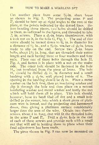
30 HOW TO MAKE A WIRELESS SET
Cut another piece from some Vs-in. sheet brassas shown in Fig. 3. The projecting arms P andP! should be bent up at right angles to the rest of the
piece, at the points indicated by the dotted lines. Be-fore bending these pieces, two holes should be drilled
in them, as indicated in the figure, and threaded to take
TVin. screws. Place a i3-in. brass thumbscrew, with
a lock nut on it, in the hole G, Fig. 1. The end of this
screw should be turned down to % in. in diameter for
a distance of ^ in., and a %-in. washer of ic-in- brassmade to slip on the end. Secure two -fVin. brass
bolts, about l 1/^ in- long, that are threaded their entire
length and each having three or four washers and four
nuts. Place one of these bolts through the hole H,Fig. 3, and fasten it in place with a nut on the underside. The other bolt should be fastened in the hole
H!, but insulated from the piece of brass. The hole
H! should be drilled -$ in. in diameter and a small
bushing with a -^5 -in. wall placed inside of it. The
opening in the bushing should be -fa in. Place a metalwasher on the bolt first, then an insulating washer and
slip it through the hole and then place on a second
insulating washer and metal washer and lastly the nutwhich will hold them all in place. This bolt should,
however, have its head filed off flat and a small hole
drilled in the center, into which a short piece of plati-
num wire is forced, and the projecting end hammereddown, thus giving a platinum surface considerably
larger than the area of the wire. Obtain two thumb-screws, about 1 in. long, that will fit the threaded holes
in the arms P and Pj. Drill a aVin. hole in the end
of each of these screws and provide each with a small
nut that will aid in holding them in place when their
final adjustment has been made.
The piece shown in Fig. 3 can now be mounted on

HOW TO MAKE A WIRELESS SET 39
a wooden base. This base can be made from a pieceof close-grained wood, about 1 in. thick, and its
dimensions should correspond to those given in Fig.4. The holes in this base should be countersunk oneach side with a %-in. bit to a depth of *4 in- so that
the nuts on the screws used in mounting will be en-
tirely below the surface. Mount two back-connected
binding-posts in the corners of the base and connectthem to the two screws with wires placed in grooves,cut in the under side of the base.
A small handle should now be turned from a pieceof hard rubber or very hard wood as shown in Fig. 5.
This handle can be mounted on the piece shown in Fig.1 with a %-in. brass screw passed through the hole Ffrom the under side. Obtain two thumbscrews about1 in. in length that will fit the holes H and I, Fig. 1
Each of these screws should be provided with a lock
nut. Drill a small hole in the end of the one youintend to put in the hole II and rivet a piece of plati-num wire in place. A screw, S, should be providedon both the pieces shown in Figs. 1 and 3, to be usedfor electrical connections.
Make a small coil spring by winding a piece of No.20 gauge steel wire around a i
3c-in. rod. The distance
between turns should approximately equal the diame-ter of the wire, and the total length of the springshould be % in. Place the end of a piece of lampcord about 4 in. long under the screw S, Fig. 1. Nowmount the piece shown in Fig. 1 upon the piece shownin Fig. 3, making sure the coil spring is in place before
the screws in the supports P and P are given final
adjustment. The other end of the piece of lamp cordcan now be fastened under the screw S, Fig. 3. Thescrews in the holes H and I can now be adjusted, giv-
ing any desired movement of the handle before the
40 HOW TO MAKE A WIRELESS SET
contact is closed. The screw G can be adjusted to
give any pressure of the spring desired.
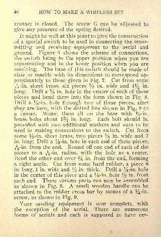
It might be well at this point to give the constructionof a special switch to be used in connecting the trans-
mitting and receiving equipment to the aerial and
ground. Figure 6 shows the scheme of connections,the switch being in the upper position when you are
transmitting and in the lower position when you are
receiving. The base of this switch should be made of
slate or marble with its dimensions to correspond ap-
proximately to those given in Fig. 7. Cut from someiVin - sheet brass, six pieces % in. wide and 4% in.
long. Drill a Vs-in. hole in the center of each of these
pieces and bend them into the form shown in Fig. 8.
Drill a %-in. hole through two of these pieces, after
they are bent, with the dotted line shown in Fig. 8 ar.
a center. Mount them all on the base with %-in.brass bolts about 1% in. long. Each bolt should be
provided with two additional washers and nuts to be
used in making connections to the switch. Cut fromsome %-in. sheet brass, two pieces % in. wide and 7
in. long. Drill a %-in. hole in each end of these pieces,
-fs-in. from the end. Round off one end of each of the
pieces to a iVm - radius, with the hole as a center.
Bend the other end over % in. from the end, forminga right angle. Cut from some hard rubber, a piece 6
in. long, 1 in. wide and l/2 in. thick. Drill a Mrin. hole
in the center of this piece and a %-in. hole % in. fromeach end. These various parts can now be assembledas shown in Fig. 9. A small wooden handle can be
attached to the rubber cross bar by means of a ^-in.
screw, as shown in Fig. 9.
Your sending equipment is now complete, with
the exception of the aerial. There are numerousforms of aerials and each is supposed to have cer-

HOW TO MAKE A WIRELESS SET 41
tain advantages and disadvantages peculiar to
itself. It is impossible to give the construction
of all the different types, as it would lead to
considerable confusion and you would be at a loss
to know just which type to use. The type described
below is known as the double-ended "T" type and it is
shown diagrammatically in Fig. 10. First of all, youmust select the location for your aerial, bearing in
mind that it should be well up in the air and, if possi-
ble, not obstructed by adjoining buildings. You canno doubt place the aerial at the greatest height withthe least trouble by supporting it on masts placed onthe roof of the highest building near your station. Thekind of mast to use will depend upon the requirements.In your case a 12 or 15-ft. mast will no doubt be
ample, and a 2-in. iron pipe will do very nicely, as it
can be easily handled. First obtain a good sized blockof wood and cut it to conform to the shape of the roof.
Then bore a hole in it that will take the pipe or woodenmast you are going to use and fasten it in place very
securely. Two or three guys should be attached to
the upper end of the mast, before it is raised. Theyshould be attached to the roof after the masts are
raised in such a way that they will not interfere withthe raising or lowering of the aerial wires. Placewooden pins in the upper ends of the pipes, and screwon them high-tension insulators. Fasten a small pul-
ley to these insulators with short pieces of seagrassline, and run sufficient ^4-in. bell cord through the
pulleys to raise and lower the aerial wires. The dis-
tance between the masts will be governed by the size
of roof, etc.;the greater this distance the better.
Cut from some well seasoned oak, two pieces l 1/^ in.
thick, 4 in. wide and 30 in. long and use them in sus-
pending the aerial wires between the masts. Cut

42 HOW TO MAKE A WIRELESS SET
notches in these pieces, as shown in Fig. 10, and tie
four porcelain knobs to each of the pieces with sea-
grass rope. The knobs should have a play of at least
4 or 5 in. The four equally spaced notches should beused in preventing the ropes from slipping along thewooden pieces. A good sized porcelain knob should betied in the center of a piece of seagrass rope about 4ft. long, and the ends tied around the wooden stretch-
ers where the remaining two notches are cut. Oneend of the ropes that pass through the pulleys on topof the poles should be tied to this porcelain knob.Run some No. 14 gauge bare copper wire through
the insulators fastened to the stringers, as shown iii
Fig. 10, and fasten the wire in place. Solder a pieceof No. 14 gauge copper wire to the points P and P^Fig. 10. In the center of this piece, solder another
piece that will lead into your instrument.The lead-in wire should be made as clear as possible,
and by that is meant to use just as few insulators as
you can conveniently get along with, since each tends
to dissipate a certain part of the high-tension current
and thus greatly lowers the efficiency of your sendingor receiving. The wire should be well taped and
passed through a heavy porcelain tube where it goes
through the wall, or a better way still would be to
drill a hole in the window pane and pass the wire
through it.

CHAPTER VI
CONSTRUCTION OF A COHERER ANDA DETECTOR
T^ ITHER the coherer or a detector may be used in' the receiving circuit. When it is desired to re-
ceive with audible signals, the coherer is used in com-bination with a relay and battery, as shown in Fig. 2.
The relay R controls a local circuit consisting of a sec-
ond battery, B 2 , and a vibrating bell, B. The use of
the detector in connection with a telephone receiver, as
used in receiving, will be taken up later.
One of the easiest coherers to make, and one that
will give excellent results when used with a sensitive
relay, is one of the ordinary metal filings kind. Thefollowing coherer has been found to give excellent re-
sults, if properly constructed. A wooden base for the
instrument should first be made from some %-in. hard
wood, about 3% in. wide and 6 in. long. Round off
the upper corners and edges of this piece and give it
two or three coats of good shellac. Obtain two goodsize binding-posts, as shown in Fig. 1. These binding-
posts should have holes in them that will allow a rs\-in.
brass rod to pass through. Mount the binding-postson the wooden base as shown in Fig. 1. Two other
binding-posts, B 3 and B 4 ,should be mounted on the
ends of the base, and back-connected to the first two.
These two binding-posts are to serve as terminals
for the coherer. Procure two pieces of g\-in. brass
rod, 2 in. long, and amalgamate one end of each of
them by first dipping the end in acid and then in mer-
cury. These rods can now be mounted as shown. A13
T 2
J-.IH

HOW TO MAKE A WIRELESS SET 45
glass tube, whose inside diameter corresponds to the
outside diameter of the rods, should be cut to such a
length that it will slip over the rods and be almost in
contact with the two binding-posts Bj and B 2 .
The ends of the brass rods inside of the glass tubeshould be separated
-LV to r$% in., providing a small
chamber, C, in which the filings are to be placed.These filings can be made from a piece of nickel, bysawing it with a medium-toothed hacksaw. Theyshould then be sifted through a thin cheesecloth or a
very fine sieve to separate the coarser filings from the
fine dust which is not desired. A small trace of silver
filings added to the nickel filings will increase the sen-
sitiveness of the coherer.
Assuming you have constructed the aerial at the
receiving end and have made the proper ground con-
nection, you can put your set in operation. You will,
of course, need a 300-ohm relay, R, Fig. 2. This relaywill cost about $7, if purchased ready made, but a
description of how to build one will be given in oneof the following chapters and its cost will be consider-
ably less. The completed connections at the receivingend are shown in Fig. 2. The switch S is the samekind of a switch as you installed at the transmittingstation. The brass rods of the coherer should be
pushed in against the mass of iron filings until the
armature of the relay R is drawn up and the bell Bstarts to ring. Withdraw the brass rods until the bell
barely stops ringing.
The distance between the armature of the relay andthe contact should not be much more than the thick-
ness of a piece of good quality wrapping paper. The
adjustment of the spring controlling the armature of
the relay will be found to be rather tedious.
It no doubt would be best to place the receiving and

46 HOW TO MAKE A WIRELESS SET
sending equipment only 10 or 15 ft. apart at first, usingshort pieces of wire hung to the ceiling for aerials,and the adjustments can be more easily made thanwhen they are quite a distance apart. The distancecan then be increased and the adjustment continued.
The vibrating bell must be mounted so that thehammer strikes the coherer a light tap when it is
vibrating. You could, if desired, make the base of thecoherer large enough so that the bell could be mountedon it permanently. A rubber band can be wrappedaround the hammer on the bell so the striking will notbreak the glass rod. The operation of this cohererhas been previously described, but it might be well to
give it again. The wave motion sent out from the
aerial at the sending station goes in all directions anda part of it is caught by the aerial at the receiving sta-
tion and passes through the coherer to the ground.The passage of this current through the filings in thecoherer causes them to cohere, this lowers the resist-
ance of the relay circuit and allows sufficient currentto flow from the battery to actuate the relay and close
the bell circuit.
The filings are decohered, of course, when the ham-mer of the bell strikes the glass rod, and the bell will
cease to operate, unless there is still current throughthe coherer which causes the filings to immediatelyrecohere. Hence, the bell will only stop ringing whenthe current ceases to flow through the coherer. Thiscurrent will flow so long as the key in the primarywinding of the spark coil at the sending station is
closed, and in this way the dots and dashes of the codeare sent.
Two types of detectors will be described the "crys-tal" and "electrolytic." It has been found that certain
metallic oxides and sulphides possess the remarkable
HOW TO MAKE A WIRELESS SET 47
property of conducting current a great deal better in
one direction than in the other, when two dissimilar
crystals are in contact. This condition is utilized in
the construction of the so-called "crystal detector."
These detectors, when connected in the aerial circuit,
will transform the electrical oscillations into a pulsat-
ing current which is unidirectional and a sound will
be produced in a high-resistance telephone receiver
connected in parallel with the detector, without the
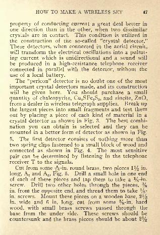
use of a local battery.The "pericon" detector is no doubt one of the most
important crystal detectors made, and its construction
will be given here. You should purchase a small
quantity of chalcopyrite, Cu2SFe 2S3 ,and zincite, ZnO,
from a dealer in wireless telegraph supplies. Break upthe largest pieces into small fragments and test themout by placing a piece of each kind of material in a
crystal detector as shown in Fig. 3. The best combi-nation you can obtain is selected and they can bemounted in a better form of detector as shown in Fig.
5. The first detector consists of nothing more thantwo spring clips fastened to a small block of wood andconnected as shown in Fig. 4. The most sensitive
pair can be determined by listening in the telephonereceiver T to the signals.Cut from some fk-in. round brass, two pieces ! 3
/2 in.
long, A t and A2 , Fig. 5. Drill a small hole in one endof each of these pieces and tap them to take a Vs-iri-
screw. Drill two other holes through the pieces, %in. from the opposite end, and thread them to take %-in. screws. Mount these pieces on a wooden base, 2 l
/2
in. wide and 6 in. long, cut from some %-in. hard
wood, with small brass screws passed through the
base from the under side. These screws should becountersunk and the brass pieces should be about 2^

48 HOW TO MAKE A WIRELESS SET
in. apart. The holes in the upper ends of these piecesshould be on a line with each other.
Make two rods, Rt and R2 ,2 l/2 in. long and threaded
their entire length, to fit the holes in the pieces A x andA 2 . Two disks, D l and D2 , 1^4 in. in diameter, shouldbe cut from some y-'m. hard wood and fastened onthe ends of the rods R! and R2 to serve as handles in
adjusting the detector. Make from some %-in. brassrod two cups, Ci and C2 . The dimensions are given in
Fig. 6. Drill a small hole in the bottom of these cupsand thread them to fit on the ends of the rods R x andR 2 . These holes should not be drilled all the waythrough the bottom of the cups.The two crystals you selected can now be mounted
in these cups by means of a composition known as
Wood's metal. This metal can be purchased at a
supply store or it can be made by melting togetherfour parts of bismuth, two parts of lead, one part of
tin and one part of cadmium. This composition meltsat a very low temperature, something like 140 deg. F.
The cups should be thoroughly cleaned and then nearlyfilled with this metal, and the crystals held in placeuntil the metal cools and hardens. Two lock nuts, N t
and N 2 , should be placed on the rods Rx and R,, as
shown in Fig. 5, to hold the cups in place after theyhave been once adjusted. Two binding-posts should
be mounted on the base and connected to the screws
on the under side of the base.
This detector can now be connected in circuit, as
shown in Fig. 4, and the final adjustment made, whichwill remain for a long period, unless it be roughly han-
dled or burned out by being placed near a strongtransmitter without proper protection. A battery, B,should be connected in series with the telephone re-
ceiver to give the b$st results.
HOW TO MAKE A WIRELESS SET 49
It might improve the sensitiveness of the detector
to construct it so that the crystals are held in contact
by means of a small spring. To do this, do not thread
the hole in one of the supports, but drill it out so that
the rod will move freely through it. A small springcan be slipped over the rod between the cup and the
support and the lock nut used in adjusting the ten-
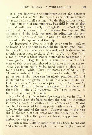
sion in the spring, it being placed on the rod betweenthe end of the spring and the cup.An inexpensive electrolytic detector can be made as
follows : The cup that is to hold the electrolyte should
be made from a piece of carbon rod, and its dimensionsshould correspond to those given in Fig. 7. Cut froma rod of brass a piece whose dimensions correspond to
those given in Fig. 8. Drill a small hole in the bot-
tom of this piece and thread it to take a %-in. screw.
Now cut from some %-in. hard wood a piece 5 in.
long and 2 in. wide. Drill the holes indicated in Fig.11 and countersink them on the under side. The up-per edges of the piece can be nicely rounded off, andit should then be given three or four coats of shellac.
Cut from some %-in. brass a piece fii/o in. long and ^in. wide. Drill a hole in the center of this piece andthread it to take a %-in. screw. Drill two other ^-in.holes, a
/4 in. from the ends.
Now bend the piece into the form shown in Fig. 9
and mount it on the base so that the hole in its centeris directly over the center of the carbon cup. Mounttwo back-connected binding-po?ts with screws throughholes in the ends of the base. Connect one of these to
the U-shaped piece of brass and the other one to thescrew that holds the piece of brass, supporting the
carbon cup, in place.Obtain a low-voltage lamp that has been burnt out
and remove the pieces of platinum wire in the base of

60 HOW TO MAKE A WIRELESS SET
the lamp. Be careful not to break the platinum wiresloose from the copper lead-in wires. Mount one of
these pieces in the end of a screw, S, Fig. 10, by sol-
dering the copper wire C in a small hole drilled in the
end of the screw. This screw should now be placedin the threaded hole in the U-shaped piece and pro-vided with a lock nut. The piece o-f platinum wire canbe raised and lowered with respect to the carbon cup.The detector should be connected in circuit, as shownin Fig. 4, with a battery in series with the telephonereceiver. Connect the positive pole of the battery to
the binding-post corresponding to the platinum-pointed screw. Fill the carbon cup with a solution,
made by adding one part nitric acid to four partswafer (always add the acid to the water) to within l
/%
in. of the top. The platinum point should just barelytouch the electrolyte. Figure 11 shows the completeddetector.

CHAPTER VII
CONSTRUCTION OF A POTENTIOMETER
THE successful operation of the detectors describedin the previous chapter will depend upon some
device for varying the current that flows through thedetector from the battery. There are ways by whichthe current can be adjusted. First, a suitable rheostatcould be connected in series with the detector and thecurrent adjusted to the desired value by changing thetotal resistance of the circuit
; second, a potentiometercould be used. The potentiometer differs from the
rheostat in that it changes the applied voltage, whichin turn results in a change in the current, the resist-
ance remaining constant, while the rheostat changesthe value of the current by changing the resistance,the voltage remaining constant. The potentiometeris widely used in connection with detectors employinga local battery, it being so sensitive that a very fine
adjustment of current can be obtained. The principleof the potentiometer will be made clear by reference
to Fig, 1. A battery, B, is connected in series with a
resistance, AC. The direction of the current flow
through this resistance is indicated by the arrow, and
any point such as D will be at a higher electrical level
or potential than some point such as E, which is nearthe end C. If a resistance, R, be connected to the
points D and E, there will be a current flow throughthe resistance, due to the potential difference betweenD and F, and the value of the current in amperes will
be equal to this potential difference, in volts, divided
by the resistance of R, in ohms. If the position of the
points D and E on the resistance AC can be changed,

V>W

HOW TO MAKE A WIRELESS SET 53
the value of the current in R can be varied, since the
potential difference between D and E will increase as
they are moved apart and decrease when they are
moved toward each other. The range of this adjust-ment would be from the full voltage of the battery,when the points D and E coincide with A and C re-
spectively, to zero, when they are connected to thesame point on the resistance AC. The resistance Rin Fig. 1 should be replaced by the detector when the
potentiometer is to be used for wireless work.
A potentiometer suitable for wireless work may beconstructed as follows : For the base, obtain a piece of
oak or other hard wood, % in. thick, 6 in. wide and 18
in. long. Round off the corners and edges on one side,
which will add greatly to the appearance, and give it
two or three coats of good shellac. Ten good sized
binding-posts should now be mounted on this base as
shown in Fig. 2. These posts should preferably be of
the back-connected type, and the screws holding themin place should be countersunk so that they do notcome below the under side of the base. Stretch three
pieces of 30 or 32-gauge bare german silver wire be-
tween these binding-posts on the upper side of the
board as indicated, in Fig. 2, by the lines Lt ,L 2 and
L3 . These wires should not be fastened between the
binding-posts and the board, but in the opening in the
binding-posts, which will raise the wires at least J/2 in -
from the board. Before fastening the binding-postsrigidly to the board, connect 1 and 7, 4 and 5, 2 and 3,
and 8 and 6 with a piece of 18-gauge copper wire
placed in grooves cut in the under side of the base.
These conductors are indicated by dotted lines in Fig.2. Obtain two pieces of lamp cord, or other flexible
wire, about 18 in. long and fasten one end of these twopieces under the binding-posts 9 and 10. The wires

54 HOW TO MAKE A WIRELESS SET
can be passed down through two holes, H x and H 2 ,
drilled in the base at the side of the binding-posts, andthe ends connected to the binding-posts on the underside. Two clips should be made and fastened to the
other ends of these wires for the purpose of makingconnections to the german silver wire.
These clips can be made as follows : Cut from somespring brass two pieces corresponding in dimensionsand form to that given in Fig. 3. Bend these twopieces into the form shown in Fig. 4, drill a small hole,
H, through the end and solder the free ends of the
wires in these holes.
In using the potentiometer, the battery should beconnected to the posts 7 and 8. It would be best to
place a small switch in this circuit so that the batterycan be readily disconnected when not in use. The va-
riable source of potential corresponds to the termi-
nals 9 and 10. The value of the potential betweenthese two binding-posts can be easily adjusted bymoving one or both of the clips along the Germansilver wire.
The various pieces of apparatus described thus far,
will, when properly connected and adjusted, give sat-
isfactory results, provided there are not too manywireless stations operating in the same neighborhood.The electrical waves sent out by any wireless station
have a certain length depending, of course, upon the
equipment making up the sending set. To obtain the
best results in transmitting signals by wireless, the
receiving and sending stations must have such equip-ment and it must be so adjusted that they have the
same wave length. When this condition is realized,
the stations are said to be in tune. Nearly everyonehas at some time heard a piano string vibrate in unison
with some note that was sounded on another musical

HOW TO MAKE A WIRELESS SET 55
instrument. The natural period of vibration of the
string corresponds to that of the note and it, as a
result, vibrates more than any of the other strings,which results in its being heard. The same condition
is true to a greater or less extent in wireless work. All
stations in the neighborhood of a station that is send-
ing will be affected, and the effect increased as the
condition of perfect tuning is approached or reached.
There are two important pieces of apparatus, the
condenser and tuning coil, that are employed in chang-ing the wave length of a given station, and their con-struction will be taken up presently. Before describ-
ing the construction, however, it might be well to ex-
plain how they are connected in the receiving circuit.
Figure 5 shows the connections of the various partsthat compose a complete receiving set. The tuningcoil T consists of two windings marked P and S
;VC
is a variable condenser (one whose electrostatic capac-
ity can be changed by an adjustment of the plates com-
posing the condenser) ;D is the detector
; TR, the
telephone receiver; E, the potentiometer, and B, the
battery.There are two sliding contacts on the tuning coil,
as shown by C t and C 2 , Fig. 5. The purpose of these
contacts is to give a means of changing the number of
turns that are effective in the primary or secondarywinding, which causes a change in the value of the
inductance of the two circuits. In addition to this
adjustment, these coils are usually so arranged that
their relative position to each other can be changed,which varies the effect one winding has on the other.
Such coils are very often spoken of as "loose coupling"
tuning coils or transformers.
The wave length of any circuit is dependent uponits inductance and capacity, and the wave length may
56 HOW TO MAKE A WIRELESS SET
be varied by changing either the inductance or the
capacity of the circuit, or both. The proper adjust-ment of the coil and condenser to give the best results
will be taken up later, after you have constructed themand are ready to operate. Two types of tuning coils
will be described, the construction being quite differ-
ent while the principle of operation ispractically
the
same in both. The first coil to be described consists of
a primary winding on a cylinder of fiber with the sec-
ondary winding on another cylinder of such size andso arranged, that it can be moved in and out of the
primary winding. One terminal of each of these
windings should be connected to a sliding or movingcontact so that the number of turns actually in use
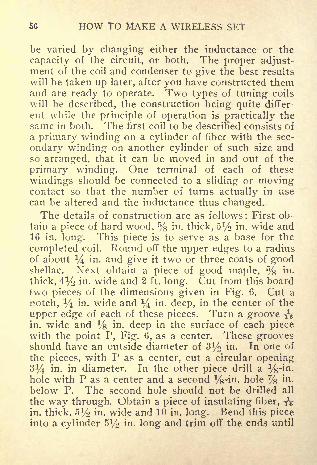
can be altered and the inductance thus changed.The details of construction are as follows : First ob-
tain a piece of hard wood, % in. thick, 5% in. wide and16 in. long. This piece is to serve as a base for the
completed coil. Round off the upper edges to a radius
of about y in. and give it two or three coats of goodshellac. Next obtain a piece of good maple, % in.
thick, 41/2 in. wide and 2 ft. long. Cut from this boardtwo pieces of the dimensions given in Fig. 6. Cut a
notch, y in. wide and a/4 in. deep, in the center of the
upper edge of each of these pieces. Turn a groove iVin. wide and % in. deep in the surface of each piecewith the point P, Fig. 6, as a center. These groovesshould have an outside diameter of 3^ in. In one of
the pieces, with P as a center, cut a circular opening3^ in. in diameter. In the other piece drill a %-in.hole with P as a center and a second %-in. hole % m -
below P. The second hole should not be drilled all
the way through. Obtain a piece of insulating fiber, iVin. thick, 5i/2 in. wide and 10 in. long. Bend this pieceinto a cylinder 5% in. long and trim off the ends until

HOW TO MAKE A WIRELESS SET 57
it is of such a diameter that it will fit into the groovescut in the two pieces shown in Fig. 6. You shoulduse considerable care in trimming the edges so that
they will fit against each other perfectly the entire
length of the cylinder. This cylinder should then be
glued into the grooves in the wooden pieces, makingsure that these are in line with each other before the
glue sets, which can be determined by resting the
lower edges of the pieces on a plane surface. If the
edges of the piece forming the cylinder do not stay in
line with each other they can be held in place in the
following manner: Wind around the outside of the
cylinder several turns of wire, drawing the ends of the
piece of fiber into place. Then glue a second piece of
fiber over the joint inside of the cylinder. Do not
remove the wire from the cylinder until the glue in the
joint has set thoroughly. Another way of formingthe cylinder, and one that will give good results, is as
follows : Obtain a sheet of thin fiber, Sy? in. wide, androll it around a wooden cylinder, 3% in. in diameter,until the wall of the cylinder thus formed is iV in.
thick. Glue each layer of the insulating fiber in placeas it is wound on, and wind the completed cylinderwith several turns of wire and allow it to dry.
When the cylinder has been fastened to the woodenblocks, it is ready for the winding, which is to consist
of 20-gauge single cotton-covered copper wire. Drill
two iij-in. holes in the under side of the cylinder, %in. from the wooden end piece without the large open-ing in it. These two holes should be drilled about MJin. apart. Pass the end of the wire to be used in
winding the cylinder down through one of these holes
and up through the other, allowing about 5 in. of free
wire to protrude. You may find it necessary to drive
a small wooden peg into one of the holes along the

53 HOW TO MAKE A WIRELESS SET
side of the wire to hold it firmly in place. The end of
this peg can be cut eft" even with the surface of the cyl-inder and should not project more than % m - inside
of the cylinder. Wind on wire until you are within
Vi in. from the other end of the cylinder. This end of
the winding can be terminated in the same way the
other end was fastened, except that no free wire to
form a terminal is needed.
Now, take a small block, cover it with a piece of fine
sandpaper and cut off the insulation, to a width of ^in., on the upper side of the wire along the top of the
cylinder and directly in line with the two grooves in
the top of the end blocks. The sliding contact is to
move along a support fastened in the two grooves andmake contact with the various turns of wire wherethe insulation has just been removed.The support for this contact can be made from a
piece of brass, !/4 in. square, fastened in the grooveswith a round-headed brass screw in each end. Makethe slider as follows : Cut from thin sheet brass a piece1 in. wide and liV in. long. Bend this piece around a
piece of iron,a/4 in. square, in such a way that the joint
will come in the center of one side. Take a small
flat-headed machine-screw of brass, about % in. long,and solder it in the center of the side opposite the
joint. A small handle can be turned from a piece of
hard rubber and fastened to this screw. Then cut
from thin spring brass a piece *4 in. wide and 2*4 in.
long. Bend this piece into the form shown in Fig. 7
and solder it to the square brass tube on the side wherethe joint was made. The complete sliding contact
can now be placed on the brass support, and the pri-
mary winding of your tuning coil is complete, as
shown in Fig. 8, with the exception of the connections
to the binding-posts that are to serve as terminals.

CHAPTER VIII
SECONDARY WINDINGS
TO construct a secondary winding suitable to usewith the primary winding described in Chapter
VII you would proceed as follows : Turn from a pieceof %-in. hard wood two disks 3 in. in diameter. Drill
two iVin. holes in one of these pieces as shown in Fig.1. Turn from the same stock another disk 3^ in. in
diameter. The edges of this disk should be roundedoff as shown in Fig. 2. Now glue the small disk with-
out the holes in it to the larger disk and then drill the
holes indicated in Fig. 3. The holes 1 to 8, inclusive,should be l
/$ in. in diameter, and their centers should
be located on the arc of a circle whose radius is 1 in.
and its center should be the center of hole No. 9. Thedistance between the centers of the holes located onthe arc should be % in. Hole No. 9 should be fa in.
in diameter.
Take eight brass machine screws, l 1^ in. in lengthand y$ in. in diameter, and file their heads down as
shown in Fig. 4. Mount these screws in the openings1 to 8, inclusive, using a small nut on the back side to
hold them in place. These screws are to be connectedto various points on the secondary winding, and a con-
tact arm, which is to form one terminal of the wind-
ing, will be arranged to move over them, giving a
means of changing the number of secondary turns
that are effective.
Obtain a piece of brass tubing 2 in. long with a wall
fa in. thick and an opening fa in. in diameter. Saw


HOW TO MAKE A WIRELESS SET 61
three slots % in- deep in one end of this piece of tub-
ing and bend each of the six parts thus formed in
toward the center so that the tube will fit very snugover a Win- rod. Thread the other end of the tubeto a distance of 1 in. and screw it into the hole num-bered 10 in Fig. 3. The protruding end should be onthe side corresponding to the smaller disk.
Take a second piece of the same kind of tubing, 3 in.
long, and thread one end for a distance of % in. andthe other end about ! 1
/2 in - Saw three slots in the
end with the larger number of threads on it, to a depthof % in. and bend the six pieces in toward the centerof the tube, as you did in the previous case. Turn a
small handle from some hard wood or rubber whosedimensions correspond approximately to those givenin Fig. 5. Drill a
^-in. hole in this handle as indi-
cated by the dotted lines and thread it so that the han-dle can be screwed on the end of the brass tube. Thehandle can then be held in place by means of a smallsetscrew countersunk in a hole at H, Fig. 5.
Make two nuts from some %-in. stock that will
screw on the threaded end of the tube. Cut fromsome thin spring brass a piece whose dimensions cor-
respond to those given in Fig. 6. Drill a %-in. hole,
Hj, in this piece. Make a washer of some %-in. brass
with an opening VA in. in diameter and an outside
diameter of 34 in. Thread this washer so that it canbe screwed on the end of the brass tube and then sol-
der it to the contact arm A, shown in Fig. G. Thelarge opening in the arm should correspond to the
opening in the washer. The dotted circle in Fig. G in-
dicates the position of the washer. After you havesoldered these two pieces together, drill two >-'m.
holes, Ho and H 3 , through both of them. Countersinkthese holes in the brass washer for flat-headed screws.

62 HOW TO MAKE A WIRELESS SET
The washer and arm can now be screwed on the endof the tube and then the wooden handle put in placeand fastened with two small screws through the holesH 2 and H 3 . Fastening the handle to the washer andarm after they are all put in place prevents the likeli-
hood of an improper alinement.
All the parts are shown assembled in Fig. 7. Asmall spiral spring, S, is placed between the two nutsX
x and N 2 ,and the washer W x , so that the end of the
arm A will always be held against the heads of the
screws. Two stops should be provided to prevent the
arm A turning too far around and dropping off the
heads of the screws. These can be made by drivingtwo small brass nails in the wooden disk as shownby N! and N 2 , Fig. 3.
The cylinder upon which the secondary winding is
to be placed can be made by winding some thin insu-
lating fiber around a round wooden piece, 3 in. in di-
ameter. This cylinder should be 6 in. long and its wall
should be iV in. thick. When the cylinder is com-
pleted, one end can be put over the disk D, Fig. 7, andfastened with three or four small screws equally
spaced around the end of the tube. The other smalldisk shown in Fig. 1 can be fastened in the other endof the cylinder in a similar manner, making sure the
holes in the disks are in line before you fasten the last
one.
The secondary part of your tuning coil is now com-
plete, with the exception of the winding, which should
be made as follows : Procure a small quantity of No.
22-gauge single cotton-covered copper wire. Drill a
small hole % in. from the end opposite the switch.
Pass about 10 in. of wire down through this hole andfasten the wire with a wooden peg. Wind on wireuntil you have covered % in- of the cylinder, then drill

HOW TO MAKE A WIRELESS SET 63
a small hole as close to the winding as you can. Makea loop in the wire you are winding on the cylinder and
pass this loop down through the hole just drilled in
the cylinder and fasten the wire securely. This loopshould be at least 9 in. long. Proceed in this wr
ayuntil you have completed the winding, which shouldconsist of eight sections.
The end of the winding farthest from the switchshould be connected to the brass tube fastened in the
hole No. 10, Fig. 3. The loops in order, numberingthem from this end of the winding, should be fastened
to the screws placed in the holes 1, 2, 3, etc. The cyl-inder must, of course, be disconnected from the block
the screws are mounted on, in order that the wires maybe soldered to the screws. The secondary windingcan now be mounted inside of the primary winding as
follows :
Cut from your %-in. stock a piece whose dimen-sions correspond to those given in Fig. 8. Drill twoTVin. holes, H x and H 2 ,
in this piece. Mount this
piece on one end of the board that is to form the base
of the instrument with two or three screws passed
through the base from the under side and counter-
sunk. This piece should be parallel to the end of the
base and % in. from the end. Mount the primarywinding on the other end of the board forming the
base, with four screws, two in each end piece. Twoback-connected binding-posts may be. mounted in the
corners of the base to serve as terminals for the wind-
ing. One of these binding-posts should be connectedto the brass rod carrying the sliding contact and the
other to one end of the winding itself. These connec-tions can be passed down through holes drilled in the
end of the cylinder and base and placed in grooves onthe under side of the base. The end of the frame for

64 HOW TO MAKE A WIRELESS SET
the primary winding should be 1% in. from the endof the base.
Obtain two pieces of brass rod -fV in. in diameterand 14% in. long. Thread both ends of these piecesto a distance of at least ^ in. Place a nut on one endof each of these and solder it in place when the surfaceof the nut and the end of the rod are flush. The endof the rod may be filed down level with the surface of
the nut after they are soldered, which will present abetter appearance. Put these two rods through theholes in the end of the primary coil, then throughthe openings in the secondary coil and finally throughthe two openings through the block on the end of the
base. The block must be unfastened from the baseso that the secondary coil can be put inside of the pri-
mary coil. Two binding-posts can now be screwed onthe projecting ends of the rods and they will form the
terminals of the secondary winding.The appearance of the coil can be greatly improved
by sandpapering all the various wooden parts and giv-
ing them several coats of good shellac. The two
windings can be shellacked, but care must be usednot to get any on the primary where the slider comesin contact with the wire.
Another method of constructing a tuning coil that
will give very good results is as follows : First make a
cylinder 4 1/2 in. outside diameter and 5 l
/2 in. long, witha wall iV in. thick, by winding some thin insulatingfiber around a form and gluing the various turns in
place. Now obtain two pieces of hard wood, 6 in.
long, 6 in. wide and % in. thick, and cut them to the
dimensions given in Fig. 9. Cut a groove in each of
these pieces as shown by the lines L t and L,. In oneof these pieces drill %-in. holes from 1 to 8 as indicated
and a i\-in. hole at No. 9. Obtain eight %-in. machine
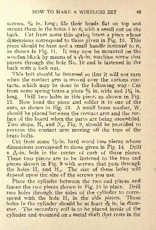
HOW TO MAKE A WIRELESS SET 65
screws, % in. long; file their heads flat on top andmount them in the holes 1 to 8, with a small nut on theback. Cut from some thin spring brass a piece whosedimensions correspond to those given in Fig. 10. This
piece should be bent and a small handle fastened to it,
as shown in Fig. 11. It may now be mounted on the
wooden block by means of a iVin. machine screw that
passes through the hole No. 10 and is fastened in the
back with a lock nut.
This bolt should be fastened so that it will not turnwhen the contact arm is moved over the various con-
tacts, which may be done in the following way : Cutfrom some spring brass a piece % in. wide and 1^ in.
long. Drill two holes in this piece, as shown in Fig.12. Now bend the piece and solder it to one of the
nuts, as shown in Fig. 13. A small brass washer, W,should be placed between the contact arm and the sur-
face of the board when the parts are being assembled.Two stops, N! and N 2 , Fig. 9, should be provided to
prevent the contact arm moving off the tops of the
brass bolts.
Cut from some %-in. hard wood two pieces whosedimensions correspond to those given in Fig. 14. Drill
a iVin. hole in the center of each of these pieces.These two pieces are to be fastened to the two end
pieces shown in Fig. 9 with screws that pass throughthe holes Hj and H 2 . The size of these holes will
depend upon the size of the screws you use.
Place the cylinder between the two end pieces andfasten the two pieces shown in Fig. 14 in place. Drill
two holes through the sides of the cylinder to corre-
spond with the hole H 3 in the side pieces. Theseholes in the cylinder should be at least -fs in- in diam-
eter. The secondary coil is to be placed inside of the
cylinder and mounted on a metal shaft that rests in the

66 HOW TO MAKE A WIRELESS SET
holes H 3 and provided with a small handle on one endso the secondary can be revolved. Before taking upthe construction of the secondary, it would be best to
wind the primary. Obtain a small quantity of No. 20-
gauge single cotton-covered copper wire and wind 120
turns on the cylinder. This winding should be dividedinto two equal parts, there being a space of about %in. between them, which will permit the shaft that is to
carry the secondary coil to pass through the cylinderwithout coming into contact with the winding. Theterminals of this winding can be secured to the cylin-der as described in Chapter VII. The insulation
should be removed from the wire and a sliding contact
constructed similar to the one described for the first
coil. This sliding contact is to form one terminal of
the primary winding, while one end of the windingitself will form the other terminal. These connections
can be made as previously described.
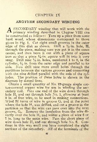
CHAPTER IX
ANOTHER SECONDARY WINDING
A SECONDARY winding that will work with the**
primary winding described in Chapter VIII canbe constructed as follows : Turn up a piece from somehard wood, whose dimensions correspond to those
given in Fig. 1. Cut eight small grooves in the outer
edge of this disk as shown. Drill a ^-in. hole, H,through the piece, making sure you get it in the exact
center, and then burn it out with a piece of squareiron so that a piece y-in. square will fit into it verysnug. Drill nine Vs-in. holes, numbered 1 to 9, in the
cylinder, 1/2 in. from the outer edge and parallel to its
axis. Now drill nine more small holes through the
partitions between the various grooves and connectingwith the nine drilled parallel with the axis of the cyl-inder. The position of these holes is shown in the
diagram by dotted lines.
Obtain a small quantity of No. 22-gauge single cot-
ton-covered copper wire for use in winding the sec-
ondary coil. Pass one end of the wire down throughhole H t and out through hole No. 1, allowing at least
8 in. of free wire, to be used in making connections.
Wind 22 turns of wire in groove Gj and at the pointwhere the hole H 2 was drilled, and cut a groove in the
partition so that the wire can pass over irito the next
groove, G2 . Remove the insulation from the wire di-
rectly over the hole H 2 and solder a piece of wire 6 or
7 in. long to the main wire. Pass the short piece of
wire down hole H 2 and out through hole No. 2. Con-tinue in this way until you have completed the eightsections of the secondary. All of the terminals of the
67

Ijf = -^ = Ip3ij I

HOW TO MAKE A WIRELESS SET 69
various sections should be brought out at the same endof the cylinder. Give the completed coil several coats
of good shellac.
The shaft upon which the secondary coil is to bemounted and the handle used in turning it can be madeas follows : Obtain a piece of brass,
a/4 in. square and
6% in. long. Turn the ends of this piece down to a
diameter of % in. as shown in Fig. 2. Turn fromsome iV-in- brass two washers % in. in diameter anddrill in each of them a V^-'m. hole and slip one of themover each end of the shaft. The wooden side pieceswill rest against these washers, which will prevent the
shaft moving endwise. In turning down the end of
the shaft, make a good square shoulder for the wash-ers to rest against. Thread the right-hand end, as
shown in the figure, to a distance of % in. Remove the
two side pieces and the end with the switch on it fromthe primary and slip the shaft in place, having placedthe secondary coil inside of the primary with the
square hole through it in line with the two holes in the
side of the cylinder. The core of the secondary can be
fastened to the shaft with a screw placed in the hole
S, Fig. 1, which will prevent it from moving along the
shaft. The core of the secondary should be turned
so that the ends of the terminals project from it towardthe open end of the cylinder. Now solder the ter-
minal from hole No. 2 to the back end of contact No.
1, Fig. 3 (Chapter VIII), and the other terminals in
regular order to the contacts 2 to 8 inclusive. Thewire projecting from hole No. 1 is to form one ter-
minal of the secondary and the center of the switch
is to form the other terminal. A piece of wire, 7 or 8
in. long, should have one end fastened to the bolt
holding the switch in place. Two small holes should
be drilled in the lower part of the cylinder and as near

70 HOW TO MAKE A WIRELESS SET
the end block as possible and the two wires formingthe terminals passed down through them. Be sure to
have sufficient slack in the wire from the secondaryso that it will not interfere with the free motion of
the core about its axis. The coil can now be assem-bled and it is ready to mount on a base with the ex-
ception of a small handle to fasten on the end of theshaft. The dimensions of a handle suitable for this
purpose are given in Fig. 3. A small screw placed in
the hole S will serve to hold the handle from turningon the shaft after it is once in place.The base can be made from a piece of hard wood
% in. thick and should be 7^-j in. wide and 8% in.
long. The upper edges and corners of this pieceshould be rounded off and it then given two or three
coats of shellac. Four back-connected binding-postsshould be mounted on the base, one in each corner,and the leads from the primary and secondary wind-
ings connected to them. The leads should be placedin grooves cut in the under side of the base.
A small condenser, constructed in such a way that
its capacity may be varied from zero to its full value
(known as a variable condenser), will be needed in
order that the best results may be obtained when youare using the tuning coils previously described. Anycondenser consists of two or more conducting plates
separated from each other by some kind of insulatingmaterial that is called the dielectric. The capacity of
such a combination of plates and dielectric is meas-ured in terms of the quantity of electricity the con-
denser will store when it is subjected to a certain elec-
trical pressure. A condenser is said to have unit ca-
pacity (one farad) when a unit quantity of electricity
(one coulomb) will raise its potential one volt. Thecapacity will depend upon the area of the plates ex-

HOW TO MAKE A WIRELESS SET 71
posed to each other, their distance apart and the kindof material separating them. In the following de-
scription of a variable condenser, use is made of the
fact that the capacity varies directly as the area of the
plates exposed, the distance between them and the
dielectric remaining constant. The construction, in
brief, consists of a stationary set of plates mounted in
a pile, all separated from each other the same distance
and electrically connected. This combination of
plates is to form one terminal of the condenser. Asecond set of plates, of practically the same area, are
mounted in a pile and electrically connected, the dis-
tance bet\yeen them being the same as the distance
between those forming the stationary pile. This sec-
ond set of plates is mounted in such a way, with respectto the first set, that the plates forming the second or
variable set may be moved into the intervening spacesbetween the stationary plates. The extent of this move-ment will determine the area of the plates forming onecombination that is influenced by the plates of the
other combination, which together with their distance
apart and the kind of dielectric used determines the
capacity of the condenser. The dielectric used in sucha condenser is usually air and their distance apart is
determined by the mechanical construction. The con-
denser may be constructed as follows :
You will need 18 pieces of metal cut to the dimen-sions given in Fig. 4, which are to form the stationary
plates of the condenser. These plates may be cut
from some thin sheet aluminum, about .04 in. thick.
Considerable care should be exercised not to bend the
sheets out of shape when you are cutting them. Drill
three %-in. holes, H lt H?and H 3 , in each of the 18
plates as shown. In addition to the above 18 plates,two more will be needed to complete the number re-

72 HOW TO MAKE A WIRELESS SET
quired for the stationary part of the condenser. Cutfrom some iVin. sheet aluminum two whose dimen-sions correspond to those given in Fig. 5. Drill in
each of these plates the holes indicated. Bend the
projecting part P down at right angles to the main
part of the plate at the dotted line D^ After this bendhas been made, again bend P at the dotted line D 2 so
that it is parallel to the main plate. A cross-section
through the plate, after these bends have been made, is
shown in Fig. 6. These plates are to be mounted in a
pile as follows : Obtain a piece of hard rubber 8 by8 in. and about ^ in. thick. Drill in this piece of rub-
ber the holes indicated in Fig. 7. Obtain three piecesof %-in. brass rod, 7 in. long, and thread them to a dis-
tance of about l l/2 in. at one end and about 1 in. at the
other. Provide each of these rods with six %-in. nuts.
Procure about 300 small washers approximately .05
in. in thickness. The outside diameter of these wash-ers should be about % in. and there should be a %-in.hole through them. Place a nut on each of the rods
on the end with the larger number of threads, then
put on ten of the small washers, and put the ends of
the rods down through the holes H,, H 2 and H 3 , shownin Fig. 7. Put two nuts on the ends of the rods that
protrude through the base and screw these nuts upuntil the last one is just flush with the end of the rod.
The first nuts you placed on the rods may now be
tightened, thus fastening the rods rigidly to the base.
Now place one of the plates, cut to the dimensions
given in Fig. 5, on the three rods with the projectingpart P toward the base. Place three washers on eachrod and then one of the eighteen similar plates. Con-tinue in this way until all of the 18 plates are in place.
After all the 18 plates are in place put the remainingheavy plate on the rods with the projecting portion

HOW TO MAKE A WIRELESS SET ?3
above the main part of the plate. Put a washer oneach of the rods and then a nut and draw all of the
plates down in place. You may experience some dif-
ficulty in not having all the plates the same distance
apart, owing to a variation in the thickness of the
washers. This can be prevented by making your ownwashers and cutting them all from the same sheet of
metal.
Cut from a piece of sheet rubber or fiber about %in. in thickness, a circular disk 7 in. in diameter anddrill three %-in. holes in it, as shown in Fig. 8, so it
will slip down on the three rods that support the sta-
tionary plates. A fourth hole, H 4 , % in. in diameter
should be drilled in the center of this plate, and three
other small ones as shown. This plate cannot be putin place until the movable portion of the condenserhas been completed, which may be constructed as fol-
lows:
Cut 19 plates from the same sheet metal you usedfor the 18 plates, to the dimensions given in Fig. 9.
Drill a T$-in. hole, H, in each of these plates. Obtaina piece of i^-in. brass rod about 5 l/2 in. long. Threadone end of this rod to a distance of 1 in. and the other
end to a distance of about 2 in. Provide four y$-in.nuts that will fit the threads on this rod. Cut fromsome hard rubber two pieces whose dimensions corre-
spond to those given in Fig. 10. Drill a hole throughthese pieces and thread them so that they may bescrewed on to the ends of the i^-in. brass rod. Placetwo of the nuts on the end of the rod with the fewernumber of threads on it and screw on one of the piecesof rubber with the larger end toward the nuts. Allow% in. of the rod to protrude through the rubber andscrew one of the nuts down on top of the rubber, whichwill serve to hold it in place. The end of the rod

74 HOW TO MAKE A WIRELESS SET
should be rounded off before the rubber piece is put in
place. Slip one of the pieces on the rod shown in Fig.9, and then three washers and then another piece, etc.,
until all the pieces are in place. The washers sepa-
rating the pieces should be the same thickness as
those separating the stationary plates and these shouldbe about % in. in diameter, which will give a larger
bearing surface. Place a nut on the rod after the
plates are all in place and screw it down. The posi-tion of the plates along the rod should be adjusted so
that they will move into the spaces between the sta-
tionary plates when the piece of rubber on the lowerend of the rod is placed in the hole in the projectionon the heavy lower plate of the stationary set. This
adjustment can be made by moving the two nuts hold-
ing the plates in place up or down on the rod. All
of these plates should be placed directly over each
other when they are finally fastened in place
The upper piece of rubber should be placed on the
rod so that it will fit in the hole in the projection in
the upper heavy plate. A nut should be placed on the
rod before the piece of rubber and it can be screwed
up against the piece of rubber after adjustment.The upper heavy plate must be removed so that the
movable portion of the condenser may be put in place.The large rubber disk can now be fastened on the
three rods by means of two nuts on each rod, oneabove and one below the disk. Before fastening the
disk in place cut from a sheet of brass, or bend ft froma strip, a piece similar to that shown in Fig. 12, andfasten it to the rubber disk as shown by the dotted
lines in Fig. 8, by means of three screws that pass upthrough the disk from the under side. File in the
upper side of this piece a number of grooves as shown
by radial lines in Fig. 12.
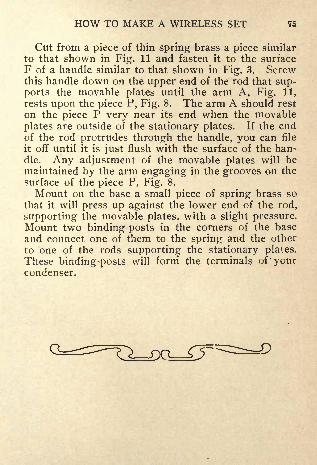
HOW TO MAKE A WIRELESS SET 75
Cut from a piece of thin spring brass a piece similar
to that shown in Fig. 11 and fasten it to the surfaceF of a handle similar to that shown in Fig. 3. Screwthis handle down on the upper end of the rod that sup-ports the movable plates until the arm A. Fig. 11,
rests upon the piece P, Fig. 8. The arm A should rest
on the piece P very near its end when the movable
plates are outside of the stationary plates. If the endof the rod protrudes through the handle, you can file
it off until it is just flush with the surface of the han-dle. Any adjustment of the movable plates will bemaintained by the arm engaging in the grooves on the
surface of the piece P, Fig. 8.
Mount on the base a small piece of spring brass so
that it will press up against the lower end of the rod,
supporting the movable plates, with a slight pressure.Mount two binding-posts in the corners of the base
and connect one of them to the spring and the other
to one of the rods supporting the stationary plates.These binding-posts will forni the terminals of'yourcondenser.


CHAPTER X
CONNECTIONS FOR SETS
THE various tuning devices described in the previ-ous chapters were designed to be used as a part
of the equipment at the receiving station. The purposeof these devices was to enable the operator at the re-
ceiving station to adjust his equipment so that it would
respond to a certain frequency wave. The frequencyof these waves is determined by the construction and
adjustment of the transmitting station. If the induc-
tion coil be connected to the aerial as shown in Fig. 1,
the frequency of the wave such a combination wouldtransmit would be fixed and there would be no way of
changing the frequency unless some change were madein the construction of the aerial. This condition of
affairs would confine the frequency at which such a
station could transmit to a single value. It is often
desirable, however, to have some means by which the
frequency of the waves sent out by the transmittingstation can be varied. With this adjustment, the sta-
tion can communicate with several different stations
whose receiving equipment is adjusted to respond to
waves of different frequencies. The theory, in brief,
upon which the construction and adjustment of the
transmitting station is based, is as follows :
If a condenser be discharged through a circuit con-
sisting of resistance alone, the current that exists in
the circuit at any instant after the circuit is closed will
be equal to the ordinate (the distance from the hori-
zontal line to the curve) of the curve at that particular
77

78 HOW TO MAKE A WIRELESS SET
instant. It will be seen from the curve shown in Fig.2 that the current is a maximum at the instant the cir-
cuit is closed and decreases in value as the time of dis-
charge increases. The decrease in the value of this
current is very rapid, it requiring only about .0001 of
a second for the current in a circuit, consisting of a
2-micro-farad condenser charged to a potential of 100
volts and connected to a resistance of 10 ohms, to de-
crease to about .06 ampere. The current in this cir-
cuit, just at the instant the circuit is closed, would be10 amperes, it being equal to the voltage of the con-denser divided by the resistance of the circuit, or 100
divided by 10 equals 10 amperes. If the condenser beconnected to a coil of wire and allowed to dischargethrough it, the current will not follow a curve such as
that shown in Fig. 2, where it is represented as dyingaway gradually, but it will oscillate back and forth in
the circuit, as shown in Fig. 3. The circuit in the sec-
ond case possesses a peculiar property called induct-
ance, which is in reality a contracted form for the word"self induction" and corresponds to what might becalled "electrical inertia." It is a property of the cir-
cuit which tends to prevent any change in the valueof the current in the circuit. Thus, if the current in a
circuit is increasing in value, there will be an increase
in the magnetic field associated with the circuit, andthis increase in the field strength will produce an elec-
tromotive force in such a direction as to oppose the
increase in the value of the current. If the current
decreases in strength, the reverse action will take
place, the induced electromotive force tending to pro-
long the current or rather prevent a change in its
value.
Oscillations will not always take place in a circuit
in which there is inductance and capacity, but certain

HOW TO MAKE A WIRELESS SET 79
conditions as to the relation between the value of the
inductance and the capacity must be fulfilled before
there will be an oscillating current produced. The"fundamental equation" of wireless telegraphy givesthis relation as follows : There will be oscillations in a
circuit provided the resistance, in ohms, is not greaterthan the square root of four times the inductance, in
henries (The henry is the unit of inductance. Referto some book on electricity for its definition.), divided
by the capacity of the condenser, in micro-farads.
An instrument termed a transmitting helix is em-
ployed at the transmitting station to furnish the in-
ductance necessary to produce the oscillations in the
circuit, and a variable condenser will supply the ca-
pacity. In addition to furnishing the inductance, the
helix acts as a step-up auto transformer and increases
the voltage of the high-frequency currents in the aerial
circuit. The helix consists of a piece of large copperconductor bent into the form of a spiral of quite a
number of turns and supported on a suitable frame.
The operation of the helix can be shown by refer-
ence to Fig. 4, which shows the induction coil, con-
denser, helix and aerial all connected. The currentfrom the secondary winding of the induction coil
passes through the condenser C and the part of the
helix that is connected between the points A and B.
This results in the condenser becoming charged, andit would discharge through the secondary winding of
the induction coil if it were not for the inductance of
the induction coil secondary, which has a large counterelectromotive force produced in it, and in order to
discharge, the circuit is completed through the sparkgap. When the adjustment of the capacity and in-
ductance in the circuit composed of the condenser C,the part of the helix between the points A and B and

80 HOW TO MAKE A WIRELESS SET
the spark gap is properly made, there will be electrical
oscillations set up in the circuit. The high-frequencyoscillations in the part of the helix from A to B pro-duce a strong magnetic field about all the turns in thehelix and, as a result, the electromotive force betweenthe points D and B will usually be greater than that
between the points A and B. The part of the helix
between D and B can be thought of as a secondarywinding, which in this case consists of the turns onthe helix between the points D and B. The electro-
motive force in this secondary part causes electrical
oscillations to be sent out into the aerial and ground.The circuit composed of the condenser, spark gap
and the turns in the helix between the points A and B,is called the "closed circuit," while the circuit com-
posed of the aerial, ground and the tur'ns in the helix
between D and B constitutes what is called the "opencircuit."
A helix suitable to be used with the other equip-ment previously described can be made as follows :
Cut from a piece of maple, or other hard wood, about
% in. thick, two circular pieces 10 in. in diameter.
Cut eight grooves in each of these pieces, as shownin Fig. 5, to a depth of % in. Cut from some 7
/s~'in -
hard wood, eight pieces % in. wide and 8 in. long.These pieces, called "struts," are to form the supportsfor the wire and should have a number of grooves cut
in them in which the wire can be placed. In order to
mark the proper location of these grooves, you should
proceed as follows : First obtain a board about 3 ft.
long and 1 ft. wide. One edge of this board should be
reasonably straight. Draw eight lines perpendicularto the straight edge of the board spacing them 3^f in.
apart. Now tack the eight struts to the board with
some very small brads, placing the edge of one of them

HOW TO MAKE A WIRELESS SET 81
along each of the lines and the ends even with the
edge of the board. The pieces must all be on the sameside of the lines. Figure 6 shows the eight pieces fas-
tened to the board B. Number the pieces 1 to 8, start-
ing with the left-hand one as No. 1. Measure off a dis-
tance of 1 in. from the lower end of piece No. 1 and a
distance of Hf in. from the lower end of piece No. 8,
marking the points on the pieces with a light lead-pen-cil mark. Make 10 other marks, % in. apart, on each
of these pieces above those just made. Now, with the
use of a straightedge, draw a line across all of the
pieces as shown in Fig. 6, by means of the brokenlines. Draw another set of lines % i- above each of
the first set and parallel to them. Cut 11 grooves in
each of the struts to a depth of % in., using the lines
that are y$ in. apart on the pieces as marks for the
sides of the grooves.
When all the grooves have been cut, the pieces canbe fastened to the two circular pieces, or heads, shownin Fig. 5. Drill a %-in. hole in each end of the eight
struts,!/2 in. from the end. Obtain 16 round-headed
brass screws about % in. in diameter at the shank and2 in. long. The eight struts should now be fastened
in the grooves in the two heads by means of the brass
screws. The struts should be placed in regular order
around the circular pieces, starting with No. 1 and
ending with No. 8. When the cage thus formed has
been completed, give it several coats of shellac.
The frame of the helix may be raised above the sur-
face upon which it is to rest by means of three woodenlegs similar to those shown in Fig. 7. These legs canbe fastened at three equally spaced places on the underside of the cage by means of two screws that passthrough the holes H x and H 2 into the tower head of
the helix.


HOW TO MAKE A WIRELESS SET 83
About 32 ft. of No. 8-gauge bare copper wire will be
needed for the winding on the helix. Drill a Vg-in.
hole through the lower end of strut No. 1 in the center
of the groove. Pass about 3 in. of the wire throughthe hole and proceed with the winding, placing the
wire in the grooves in the struts, using considerable
care in not bending the wire too abruptly where it
passes over the various struts. A %-in. hole can be
drilled in the center of the upper groove in strut No.8 and the end of the wire passed through it, which will
serve to hold the winding in place.
The two ends of the winding should be given onehalf turn around the struts through which they passand two small binding-posts may be soldered to themto serve as terminals to the coil.
The connections A and D, Fig. 4, can be made bymeans of two small clips soldered to the ends of flexi-
ble cords. These clips can be made as follows : Turnout of some hard rubber two pieces whose dimensions
correspond to those given in Fig. 8. Cut from some
spring brass two pieces similar to the ones shown in
Fig. 9. Drill a small hole, H, in this piece, as shownin Fig. 9, and bend it into the form shown in Fig. 10.
Obtain two pieces of good rubber-covered wire, about3 ft. long (preferably a flexible conductor), pass oneend through the hole H in the rubber handle, as shownin Fig. 8, and solder it in the hole H in the piece of
spring brass shown in Fig. 10. Pull the wire back
through the handle and force the spring clip in place.After the clip has been forced into place, a piece of
rubber should be cut and placed between the two parts
P! and P 2 as shown in Fig. 10.
In the operation of a transmitting station such as
that shown in Fig. 4, it is desirable to know the value
of the current in the conductor to the aerial so that the

84 HOW TO MAKE A WIRELESS SET
proper adjustment of the circuit may be made in orderthat the energy transmitted by the station be a maxi-mum. The only instrument suitable for the measure-ment of this current is a hot-wire ammeter. Its ope-ration depends entirely upon the heating effect of acurrent and its indications are not influenced on ac-
count of the direction of the current changing. If a
hot-wire ammeter of suitable range is obtainable, the
adjustment of the sending station can be made as fol-
lows : Connect the ammeter in circuit as shown in Fig.11. Place the two movable clips Q and C 2 on the
helix near its center, close the key in the primary cir-
cuit and note the ammeter reading. Move both the
clips along the helix until you find the point giving a
maximum indication on the ammeter. Fasten the
clip C 2 at this point and then move Q until you getthe maximum reading on the ammeter. When this
adjustment is secured, the two circuits are in "tune."
Figures 1, 4 and 12 show three different types of
sending sets, while figures 12, 13 and 14 show three
different types of receiving sets. Figure 1 shows an
"open-circuit sending set," Figure 4 a "tuned sendingset" and Figure 12 a "loop aerial system" for sending.
Figures 13 and 14 show two "tuned receiving sets"
and Figure 12 a "loop aerial system" for receiving.
The letters in the above diagrams refer to the follow-
ing apparatus :
B BatteryC Fixed Condenser.D Detector.G Ground.H Helix.K Key.L Lead to Aerial.P Potentiometer.R Telephone Receiver-
AG Anchor Gap.AS Aerial Switch.1C Induction Coil.LT Loose Coupled Coil.
PC Plate Condenser.SG Spark Gap.ST Straight Tuning Coil.
VC Variable Condenser-

New Revised Enlarged Edition
of Our Popular Book for Boys
Mechanics forYoung America
Gives plain directions for making scores of articles which
delight the heart of the average youth. This volume has been
thoroughly revised from cover to cover and improved where
possible. Much entirely new matter has been added makingthe book unusually instructive and interesting.
Some of the things which it tells how to make are:
Boats of Many Kinds
Magic Lantern
Electric SearchlightSmall SteamboatElectric EngineModel Yacht
Sailing Cycle
Paper AeroplaneWater Bicycle
Water MotorsIce Boat
Bell Tent
Camps and How to Build ThemSmall Steam Turbine
Fishing Tackle
Crossbow and ArrowCoin Purse
CameraKites of Many KindsOverhead Trolley Coaster
Electric Furnace RegulatorOrnamental Iron WorkDevices for Winter SportsHome-Made Roller Skates
Trailer for a Bicycle
Combination Telegraph andTelephone Line
Price 25c Postpaid
Mechanics
AmericaA Bookfor Boys
~ iHowtoBuiMBOATS. WATER MOTORS. WIND MILLS.
CLECTRIC BURGLAR ALARM. ICE BOATBICYCLE. CABLNS. CAMPS. CLOCKS.
ING TACKLE. KITES. IMTTAT1C
PRICE 25 CENTS
150 Articles, 128 Pages, 221 Illustrations
Order of your newsdealer or send direct to the publisher
POPULAR MECHANICS CO.CHICAGO

Amateur Mechanics No. 1
A Valuable BookOf Exceeding Interest to the Practical Mind
FOR BOTH OLD AND YOUNGPart Contents
Acetylene Gas Generator, Home-MadeAlarm, Callers' ApproachAlarm, Cheap FireAlarm, Combined Door-bell and ElectricArc Light, Home-MadeAuto, Young Mechanic BuildsBatteries, Connecting to give any VoltageBoat, Paddle, How to MakeCamera, Pictures WithoutCannon, How to MakeDoor Opener, ElectricDraft Opener, AutomaticElectric Lighting, MiniatureElectric Lamps, Experiments withElectrical Experiments, InterestingElectro- PlatingFoundry Work at HomeFurnace, Small BrassHammock, Barrel StaveIncandescent Lamp, Lighting with
Induction Coil
Jump Spark Coil, How to MakeKite, Box, How to MakeLathe, How to MakeLock, AutomaticLocomotive, Neat ModelMagic, ParlorMotor, Small, ReversingPhotographs, Freak, How to Make
Rheostat, BatterySteam Engine, Toy, How to MakeTelegraph Line, One-WireTelescope, Farmer s Boy BuildsToboggan Sled, How to BuildWireless Telegraph, How to Make
Contains 1 74 Articles
Price 25 cents postpaid
=165 Illustrations
"Amateur Mechanics" is a thorough, practical book for oldand young. Tells how to make hundreds of different articles
of daily use. This book should be in every American home.
"Written So You Can Understand It'
For sale by all Newsdealers or may be ordered direct from thePublishers
Popular Mechanics Book Dept.CHICAGO

Amateur Mechanics No. 2Price 25 cents, postpaid
Bigger and better than No. 1; contains entirely
different matter, yet along the same interesting,
practical lines; tells how to make hundreds moredifferent articles of daily use, among which are :
Air ThermometerAmmeterArts and Crafts Leather WorkBalloon, PilotBarometerBattery Cell, DryBattery, Small StorageBicycle CatamaranBoomerangsCandle ShadeCanoe, SailingCart, Home-made DogCoil, InductionCopper TraysElectric Lamps, MiniatureElectric Locomotive, MiniatureElectric Post Card ProjectorFlash LampFlying MachineGeissler Tube, SmallGlider, AerialInduction MotorKite ReelLamp Stand and ShadeLantern Slides
Library Table, MissionMerry-Go-Round SwingMicrometerMicroscopeMotor, SmallMotorcyclePocket LampPuntRabbit Trap, Self-SettingRustic SeatStage, MiniatureStatic MachineVolcano, Miniature
NUMBER 2 25 CENTS
Water WingsWindmill, StationaryWireless Telegraph, SimpleWireless TelephoneWorkbenchX-Ray Instrument
Interesting to the Practical Mind, Both Old andYoung, and "Written So You Can Understand It"
128 Pages 193 Articles 196 Illustrations
For sale by all newsdealers or may be ordered direct from publishers
POPULAR MECHANICS BOOK DEPT.318 W. Washington St., Chicago

Mission Furniture
|50c| How to Make It|
50cPART I
THISis the first of a series of handbooks on industrial
subjects to be issued from time to time by POPULARMECHANICS. This book consists of a number of
articles telling how to make a large assortment of pieces of
mission furniture. It is fully illustrated and the directions
are accompanied by dimensioned working drawings.
Like POPULAR MECHANICS, it is \nplain, simple lan-
guage and "Written so you can understand it," so that anyone
possessing a slight knowledge of how to use tools can easily
make the various pieces described.
Among the contents are:
Forty Styles of Chairs, An Easily Made Book-Shelf, How to Make a Porch
Chair, A Portable Table, A Pyrographer's Table, How to Make a Mission
Library Table, How to Make a Lamp Stand and Shade, How to Make a
Roman Chair, A Home-made Mission Chair, A Home-made Mission Book-
Rack, How to Make a Tabouret, Another Mission Chair, How to Make a
Roll Top Desk, Home-made Lawn Swing, A Mission Candlestick, How to
Make a Magazine Stand, How to Make a Blacking Case, How to Make a
Mission Shaving Stand, How to Make a Piano Bench, A Dresser for a Child's
Play-room.
It has 96 pages; is attractively bound in cloth covers, and can
be ordered ofany newsdealer in the U. S. or will be sent to anyaddress upon receipt of the price, 50 cents, by the publishers.
Popular Mechanics Book Dept.
CHICAGO

PART TWO
Mission FurnitureHow to Make It
32 New and Approved Designs
A Large and Varied Selection
of Immensely Popular Pieces,
Among Which Are:
Two China Closets TwoArm Chairs RockerSide Chair Mantel Clock
Lamp Stand Two FootStools Bookcase Maga-zine Table SmokingStand Wall Case Waste
Paper Basket MusicStand HallClock CedarChest Child's Dresser
Couch Oil LampGrill Two Writing Desks
Library Set Buffet
Bedstead Dining Table
Medicine CabinetTelephone Stand Plate
Rack Dining RoomShade.
Complete dimensioned
working drawings, ex-
plicit instructions howto make, and half-tone
illustrations of the fin-
ished pieces.
Special Features Are:
Articles describinghowto produce the different
finishes and showingmethods of makingjoints and bendingwood.
"Written So You CanUnderstand It"
May be ordered of any news-dealer in the U. S. or will be
sent to any address postpaid
upon receipt of the price,
50 cents, by the publishers.
128 Pages, Clotb Cover
POPULAR MECHANICS COMPANYCHICAGO

Art-Crafts LampsHow to Make Them
By JOHN D. ADAMS
Portable Reading Lamp
16 Beautifu! DesignsAs Follows :
Two Light Portable-Portable Reading Four
Light Chandelier Read-
ing Lamp Dining RoomDome Porch or DenLantern Four LightChain Hung Chandelier
One Light Portable Lan-
tern Drop Light One
Light Bracket Piano
Lamp Wall Lamp Elec-
tric Candle SconceNewel Post Lamp Chain
Hung One Light Bracket.
PRICE 50 CENTS
Plain Instructions Dimensioned Detail Draw-
ings and Illustrations of Each Finished Design
A handy little working manual of 96 pages, printedon the best quality of book paper and handsomelybound in cloth. Supplied by your newsdealeror may be ordered direct from the publisher
Popular Mechanics Book DepartmentCHICAGO, ILL.

A GOOD, USEFUL BOOK
Wood-Working for
Amateur Craftsmen"WRITTEN SO YOU CAN UNDERSTAND IT"
By IRA S. GRIFFITH, A. B.
128 Pages, 125 Illustrations
Cloth Cover, Size 5x7 inches
Price
50 CentsPostpaid
One of the latest of Popular Mechanics Seriesof Industrial Handbooks
This book was especially designed to cover everyessential step from the A B C to the X Y Z of wood-
working. The chapters dealing with making special
articles bring out every cut, joint and process used in
this important trade, and the proper use and care of
tools, working up of materials, etc., are treated
thoroughly and plainly.
CONTENTS:Making Out a Stock Bill Laying Out Rough Stock HandSaws Sawing with Hand Saws Planes: How to Set andAdjust the Irons-Squaring Up Mill Planed Stock Squar-ing Up Kougli block Whetting Plane Irons and Chisels-Grinding Plane Irons and Chisels Making a Bird Box-Making a Tabouret How to Make an Umbrella Stand Mak-ing a Magazine Stand Making a Table Making a Cabinet.
A valuable book for either self instruction oruse in manual training courses
Order of your Newsdealer, Bookseller or direct from
Popular Mechanics Book Dept., Publishers
CHICAGO, ILLINOIS

Metal SpinningBy PROF. F, D. CRAWSHAW
Assistant Dean, College of Engineering
University of Illinois
METAL SPINNING is one of the
Mechanics Handbook Series and has 80 pages
33 illustrations, is bound in attractive cloth
covers and printed on a fine quality of paper.
This handbook is unique in that it is the only book pub-lished on this interesting art, instructions regarding which
have previously been handed down by word of mouth from
generation to generation of expert metal spinners.
It is "Written so you can understand it" by a man well
qualified because he has made a thorough study of all obtain-
able information on the subject. He has tried out the different
methods himself and herein he sets forth the best practice.
Concise, yet complete, this book is adapted to use as a
text in manual training and industrial schools and will be
found a practical working manual both by those who desire
to spin metal as an art recreation and those who wish to
follow this work as a trade.
Explicit instructions are accompanied by figures to illus-
trate the meaning. It tells not only what tools are required,but how to make each kind. Definite forms to be spun are
treated, and finally the unclassified and more difficult work is
dealt with.
f^rm rente:- Chapter i, The Laihe and Its Uses; ^, Tools; 3, The
Preparation of Metal for Spinning; 4, How to Spin a
Shallow Dish; 5, How to Spin a Deep Dish; 6, How to Spin a Vase; 7,
How to Spin Some Unclassified Forms.
Price SO Cents, Postpaid
Popular Mechanics Book Dept.CHICAGO
Metal Work and Etching"WRITTEN SO YOU CAN UNDERSTAND IT"
By JOHN D. ADAMS
ONEof the latest of the POPULAR
MECHANICS series of industrial
handbooks. A complete manual for
art metal workers giving every detail for
making a great variety of useful and orna-
mental objects such as book ends, desk sets,
pad corners, paper knives and letter openers,
stationery racks, rocking blotter, desk calen-
dars, match boxes, tie and pipe racks, whiskbroom holders, candle sconce, arts and crafts
jewelry, hinges, drawer pulls, etc.
p<5 Pages, Richly Illustrated, Cloth, Size fx? Inches
Price, SO Cents, Postpaid
ORDER OF TOUR NEWSDEALER, BOOKSELLER, OR
Popular Mechanics Book Dept, Publishers
CHICAGO

NOW READY
WRITTEN SO YOU CAN UNDERSTAND IT
BY HENRY C. REETZ
PRICE 5O CENTS POSTPAID
112 PAGES FULLY ILLUS., CLOTH COVER, SIZE 5X7 IN.
One of the latest of Popular Mechanics Series of
Industrial Handbooks
handbook gives brief and practical direc-
tions calculated to be of benefit to those alreadyengaged, as well as to those about to engage, in the
electroplating business, with no more technical
detail than is necessary for practical work, andyet with such explicit directions concerning theactual operations as an old hand at the businessthinks may be useful to the beginner.
CONTENTS:Introduction Electrical Equipment Shop EquipmentCleaning Goods before Plating Copperplating Nickelplating
Silverplating Goldplating Miscellaneous First Aid to
the Injured Business Suggestions.
===== Order ot your Newsdealer, Bookseller or ==========
POPULAR MECHANICS BOOK DEPT.PUBLISHERS CHICAGO


r of California
from which it was borrowed^
AUG 1 8 1993
DEC 2 199?
EMS

A 000 036 431 5
