19158 pressurized water reactors john r. weeks …
TRANSCRIPT

19158
CORROSION OF STEAM GENERATOR TUBING IN OPERATINGPRESSURIZED WATER REACTORS
JOHN R. WEEKSMATERIALS ENGINEERING BRANCHDIRECTORATE OF tICENSING *
USAEC, WASHINGTON, D. C. 20545
ABSTRACT
Corrosion of steam generator tubing has been observed inall but three PWR's that have been in operation for storethan one year. The history of this experience with bothstainless steel and Inconel-600 tubing is reviewed.Both intergranular stress corrosion cracking and local-ized, transgranular wastage have been observed withIncone1-600 tubing. The wastage can be attributed to alocalized concentration, or "hideout" of phosphates inlimited flow areas. A model is proposed for this wast-age phenomenon which is consistent with operatingexperience.
INTRODUCTION
Corrosion of steam generator tubing has been observed in all butthree of the fifteen pressurized water reactors (FWR's) in the U, S.that have been in commercial operation for more than one year as ofJune, 1974, as well as in five similar plants in other countries (1,2, 3, 4, 5). The extent of damage has ranged from shallow attack on afew isolated Lubes in some plants to complete penetration of severaltubes accompanied by measurable attack on nearly half the tubes in oneplant. Thus corrosion of steam generator tubing has become a genericproblem of a magnitude that was totally unexpected with Inconel-600tubing. In this paper, this operating experience will be summarizedand a possible mechanism proposed for the observed wastage phenomenathat is consistent with this experience.
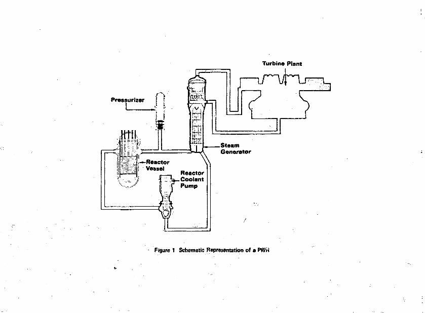
Figure 1 is a schematic drawing of a typical PWR, taken from theWestinghouse Steam Generator Symposium (1). In the steam generators,the heat from the primary coolant is used to produce steam, which inturn passes through the turbine-generators to the condensers, wherethe waste heat is removed. Typical dimensions and operating parame-ters for the current design of nuclear steam generators are given inTable 1, taken from the Standard Safety Analyses Reports submitted byWtst inc.house (6) and Combustion Engineering (7) and The Babcock andWilcox Company (8).
-Present address: Erookhaven National Laboratory, Upton, N.Y. 11973
- N O T I C E -This repott was prepared as an account of worksponsored by the United Staces Government. Neitherthe United States nor the United Slates Atomic EnergyCommission, nor any of their employees, nor any oftheir contractors, subcontractors, or their employees,makes any warranty, express or implied, or istumes anylegal UabUity or responsibility for the accuracy, com-pleteness or usefulness of any information, apparatus,product or process disclosed, or represents that its usewould not infringe privately owned rights.
DISTRIBUT ION c ;:••: > ':...-. .
h

Figures 2 and 3 are cutaway drawings of U-tube steam generatorsof the type manufactured by Westinghouse (9) and Combustion Engineer-ing, (10) respectively. To restrain the tubes from vibration, aseries of supports are required for the straight portions of thetubes, and a series of restraints either in the form of anitivibrationbars (Figure 2) or "bat-wings" (Figure 3) are used for the curvedportions of the tubes. These supports frequently serve the additionalfunction of baffling the flow of the secondary coolant to produce alateral as well as vertical component to the flow. Figures 4 from (1)and 5 from (11) are photographs of steam generator tubing bundles inthe assembly stage, and show the relation between the tubes and tubingsupports.
STEAM GENERATOR WATER TREATMENT
Impurities carried into the steam generator by the feedwater tendto concentrate there, and precipitate as boiler scale on the high heatflux surfaces. The main sources of these impurities are corrosion ofmaterials in the turbine, condenser, and feedwater piping, andinleakage of the tertiary coolant into the condensate. Two approachesto steam generator water treatment have been followed to control theformation of this cale: a "volatile" treatment in which the pH ofthe deionized water in the steam generator is raised and the oxygenscavangered by volatile additives such as hydrazine or morpholine,and a coordinated phosphate treatment in which sodium phosphates areadded to the coolant to raise the pH and react with scale-formingImpurities to produce relatively harmless soft phosphate precipitates,coupled with additions of hydrazine, morpholine, or sodium sulfite to
>ji scavange the oxygen. Both approaches have been used successfully insome instances; both have led to difficulties in some instances.
THE "VOLATILE" TREATMENT OF STEAM GENERATOR COOLAHT
In a U-tube steam generator of the types shown in Figures 2 and3, recirculation ratios of boiler waters generally range from 2/1 togreater than 5/1. Therefore it is not deemed necessary to maintainextremely pure water in the steam generators at all times. Hydrazineand/or morpholine are added to the feedwater as required to maintain,a pH in the rage 8 to 9. The coolant is continuously monitored forpH and conductivity, and periodically sampled and analyzed for dis-solved and suspended solids. High conductivity and Impurity levelsin the coolant are removed by blowdown and additions of deionizedmakeup water. Typical normal operating limits are given in Table 2,taken from (12). Condenser inleakage of impurities is indicated bycondensate conductivity monitors. Continuous demineralization of allor part of the condensate is being considered for some plants (13,14).

For plants with "once-through" steam generators, full-flowcondensate demineralization and extremely stringent control of feed-water purity are required to prevent scale formation on the tubes.Typical operating limits for impurity levels in once-through boilersare also given in Table 2, taken from (8) and (13).
THE COORDINATED PHOSPHATE TREATMENT OF STEAM GENERATOR COOLANT
This method has been used in most PWR's. In principle, demineralizedwater is used for the secondary coolant to which disodium orthophos-phate (Na2 HPOtt) is added to form insoluble, but soft precipitatesof metal (I.e., Fe or Ca) phosphates which can, in principle, beremoved by blowdown (1, 9). The reaction sequence that occurs can bedescribed as follows for Ca tons entering the solution through con-denser inleakage as Ca (HCO3)2:
6 Na2 HPOu + 3 Ca (HCO3)2 •* Ca3 (P0i,)2 + 4 Na3 POi* + 6 C02 + 6 Hz0 [1]
but trisodium phosphate tends to hydrolyze in solution by the reaction
Na3 POi, + H20 * Na2 HPOi* + NaOH [2]
so that the end products become calcium phosphate and sodium hydrox-ide; consequently, without proper controls, conditions that promotecaustic stress corrosion cracking can develop.
Reaction [2] tends to proceed to the right as written unless theaverage tnol ratio of Na/POi, in solution is equal to or less than2.6/1 to 2.8/1, depending on the temperature, the nature of other ionsIn solution, etc.;. pH changes also occur during these reactions. Thegeneral relation between pH, concentration of phosphate ions, andtendency to form free caustic is given in Figure 6, taken from thework of Marcy and Halstead (15) as adopted by Westinghouse (1, 9).
The pH of the secondary watsr will be raised by reactions similarto [1] and [2] only if the metal ions that precipitate as phosphatesenter the condensate in the form of hydroxides (i.e., Fe0-H20 orFe(OH)2£rom corrosion products) or carbonates or bicarbonates. Metalchlorides or sulfates entering the condenser (i.e., CaCl2 or MgSOi,)will tend to lower the pH of the secondary coolant by reactions of thetype,
3 MgSOi, + 2 Na2HPOn -> Mg3<PO[f)2 + 2 Na2SOit + H2SOi, [3]
Inleakage of traces of NaCl should not have an effect on the solutionpH, since no insoluble phosphates are formed.

Condenser leakage at inland locations where hard waters arecommon will, in general, tend to raise the solution pH and may promotecaustic attack. Condenser leakage at coastal plants will, in general,tend to lower the solution pH (due to NgCl2 intrusion) and may promoteacid attack. Consequently, any secondary water monitoring programmust be designed with the composition of the condenser coolant inmind to give adequate warning of condenser leakage.
In the application of the coordinated phosphate treatment,phosphates are normally added continuously to the secondary coolantas disodium phosphate, or a mixture of di-and trisodium phosphates.The phosphate sludge is removed, along with other impurities in thesteam generator coolant, by continuous blowdown (1, 9). Typicaloperating limits and sampling controls are shown in Table 3, takenfrom (9).
CORROSION PHENOMENA
The concentrations of impurities found in steam generatorcoolante would normally be harmless to the materials of construction,primarily Inconel-600 and carbon or low alloy steel. However, theheat flux through the steam generator tubes provides a concentratingmechanism for impurities. The surface of the steam generator tubingis generally 25-50°F hotter than the surrounding coolant. Ideally,as steam bubbles form at the surface, there is sufficient turbulencein the coolant to sweep them away and prevent increases in concentra-tion and/or precipitation of impurities on the tubing surface.However, the need for mechanical restraint of the tubes to dampenvibration, and the tendency for sludge to accumulate on the surfaceof the tube sheet and/or tube supports can give rise to local siteswhere the coolant is boiled away more rapidly than it is replaced,and therefore, locally high concentrations of impurities.
Figure 7 shows a schematic representation of the concentratingprocesses in the area of sludge deposition on the tube sheet surface,taken from (1). Similar concentrating mechanisms are applicable inthe vicinity of tubing supports of the type sketched in Figure 8, andin tv.\,e to tube sheet crevices, of the types shown in Figure 9, takenfrom Weber and Sury (16). Concentration factors ofJiiO1* have been " .postulated to occur in these areas, so that a few ppm of NaOHproduced by a reaction sequence of the type given above, or by lnleak-age of impurities (such as NajCC^ or KM)3) that tend to decompose toform caustic in the steam generator (17), can build up locally toseveral weight percent and give rise to stress corrosion cracking ofthe Inconel tubing, especially in the hot leg side of the U-tubesteam generator, where the temperature differential between theprimary and secondary coolants is the greatest. Phosphates also tendto be concentrated (hideout) in these areas, and then to reappear insolution whenever a power reduction and its concomitant reduction in

heat flux allows the coolant to flush out these areas (inversehideout). The experience with inverse hideout in one plant isdescribed in Table It, taken from (18). These hideout phenomena haveled to stress corrosion cracking or a general wastage attack inoperating plants.
STRESS CORROSION CRACKIHG
Stress corrosion cracking of the Inconel-600 tubing by hideoutof NaOH in the tube to tube sheet crevices or in the area of sludgebuildup on the tube sheet has produced leaks in several plants (1, 2,3, 4, 5, 16). Careful control of the phosphate additions in the man-ner described above and in Table 3 has been demonstrated to eliminatethis attack (1), as described below under plant operating experience.Intergranular stress corrosion cracking of Inconel by pure water increvice areas has been reported in laboratory tests, but has not beenobserved to date in operating steam generators. Figure 10 shows amicrograph of the intergranular stress corrosion that occurred justabove the tube sheet in one plant.
WASTAGE OR PITTING ATTACK
A generalized transgranular corrosion or wastage of Inconel-600has been observed in the vicinity of tubing supports of the type shownin Figure 8, or in the area of sludge accumulation above the tubesheet.
This attack has only been observed with the coordinated phosphatetreatment of steam generator coolants, and is believed to be caused bya reaction between nickel and sodium hydrogen phosphates. A mechanismfor this attack is proposed in the discussion section below. Figure11 shows the nature of the attack in the vicinity of tubing supportsin one plant (14).
A similar phenomenon has been observed in one plant after anextended period of "dry layup," during which the coolant had beendrained, and the steam generators filled with air, without the sludgedeposits having been dried (18). In this case the pits were observedboth in areas in which wastage had occurred during operation of theplant, and in new areas, unrelated to "normal" areas of sludge deposi-tion, in the upper half of the steam generator tubing. This attack isshown in Figure 12. A local intergranular attack was found in thesame general area, a micrograph of which is also shown in Figure 12.
CORROSION EXPERIENCE IK OPERATING FWR's
The author has prepared a derailed review of the corrosionexperience in each operating PWR.

This experience Is summarized below.
PLANTS WITH STAINLESS STEEL STEAM GENERATORS
Five of the early commercial nuclear power stations were builtwith stainless steel steam generators. These include Shippingport,Yankee - Rowe, Indian Point-1, and the Hanford "N"-reactor, which arePUR's, and Peach Bottom-1, a gas-cooled reactor. Sensitization of thestainless steel tubing during heat treatment of the carbon steel tubesheets led to stress corrosion cracking and leakage in the "N"-reaccorand in Peach Bottom-1 during the preoperational hydraulic pressuretests (4). The steam generators of both plants were retubed prior tostartup, the "N"-reactor with Inconel-600, and Peach Bottom-1 withIncoIoy-800. Leaks due to stress corrosion cracking developed atShippingport within 200 hours of power operation in December, 1957(4). A high phosphate treatment was then adopted (100-300 ppm addedas NagHPOj,) (19) and the plant operated until 1964, when the steamgenerators were replaced with larger units tubed with Inconel-600(20).
Indian Point-1 (21, 22) and Yankee - Rowe (23) have had a seriesof shutdowns for steam generator leaks. Both plants use a zero solidswater treatment to minimise the probability of stress corrosioncracking (22, 24). Neither uses condensate demineralization. Mostof the problems at Indian Point-1 have been in one area of one(horizontal) steam generator, where the tubing supports have sagged,creating a locally high stress on the tubes (22).
PLANT WITH mCOLOY-800 STEAM GENERATORS
Since the steam generators at Peach Bottom-1 were retubed (in1967) with Incoioy-800, no corrosion problems have developed (25).Inscrvice eddy current inspections have revealed no defects. A zerosolids treatment of the secondary coolant is used, with full-flowdemineralization of the condensate. During layup periods the steamgenerators are blanketed with nitrogen.
PLANTS WITH INCONEL-600 STEAM GENERATORS
Plants Using a Zero Solids Treatment:
Four plants have operated for more than one year with a zerosolids treatment of their secondary coolant. No steam generator cor-rosion or leakage has occurred at Maine Yankee (14) and Oconee-1 (26).The wastage attack observed at Shippingport when phosphate chemistry

was used was essentially eliminated by the adoption of a zero solidswater treatment in 1971 (20). Stress corrosion cracking of the steamgenerator tubing occurred in the crevice between the tubes and tubesh^et at Beznau-I during the initial zero solids operation (1, 16).Condenser inleakage occurred during this period, which is believed tohave Introduced impurities (such as nitrates or carbonates of sodiumor potassium) that partially decomposed in the steam generators toform hydroxides of sodium or potassium, which in turn led to stresscorrosion cracking ot the tubing. The possibility that attack couldhave been a manifestation of the stress corrosion of Inconel tubing by"pure water" in crevice are AS cannot be discounted at this time.
The 10 of the 12 steam generators in the "H"-reactor that wereretubed with Inconel-600 prior to startup have operated in a trouble-free manner since April, 1966, with no measurable leaks detected dur-ing pressurization, other than a slight weepage of F18 (27). (LeeksIn the two remaining stainless steel steam generators have caused anaverage of two tubes per year to be plugged.) Feedwater is limited toISOppb Cl~. Full-flow condensate demineralization is available forstartup or shutdown conditions, or whenever condenser leakage occurs.The tubes were expanded the full depth of the tube sheet by rolling,as in Figure 9C.
Plants Using a Coordinated Phosphate Treatment:
Seven plants that started operation in the period 1967-71 usedoriginally a low (5-10 ppm) phosphate treatment of the secondarycoolant. Because of condenser inleakage, it has been found difficultto maintain phosphates in this range without free caustic developingfrom reactions such as [1] and [2]. Consequently, stress corrosioncracking of the tubing in the area of sludge buildup on the tubesheet surface has occurred in several of these plants, includingConnecticut-Yankee, Point Beach-I, H. B. Robinscn-II, Zorita (inSpain), and in Beznau-I after the water chemistry was switched to alow phosphate treatment in September, 1971 (1). At the same time thatstress corrosion was developing in the above cited plants, steamgenerator leaks due to wastage developed in the vicinity of tubingsupports in Mihama-1 (1), Palisades (28) and Shippingport (20). Ofthese, Mihama-1 and Palisades were operating on a low-phosphatechemistry (14), and Shippingport on a high (100-300ppm) phosphate 'chemistry (19). Only the K. E. Ginna and San Onofre plants operatedwithout steam generator corrosion when using a low phosphatetreatment.
In mid-1972, the low phosphate treatment was abandoned at allthe above-cited plants (except Shippingport, which switched to zerosolids in 1971) in favor of a higher coordinated phosphate treatmentof the type described above, and in Figure 6, coupled with, in mostcases, continuous blowdown in an attempt to minimize sludge buildup(1, 9). This change appears to have eliminated the stress corrosion

cracking phenomenon; in the Robinson-II plant, a 75% through wallstress corrosion crack observed originally in 1972 was reinspected oneyear later and found to be unchanged following the increase inphosphate concentration (29).
However, increasing the phosphate concentration appears to haveincreased the probability of wastage developing in the area of tubingsupports at Palisades and Mihama-1 (14), and in Che area of sludgebuildup on the tube sheet in R. E. Ginna (30), San Onofre 1 (1) andZorita (1) of the older plants, and in Beznau-II (1) and Surry-I (1?)both of which started up with the higher phosphate treatment.Measurable wastage has been observed on nearly half the 8000+ tubesin each steam generator at Palisades (31), and «n approximately 15%of the tubes of the tubes in one of the Ginna steam generators (30).Further, significant additional wastage occurred at 'Palisades duringthe "dry" layup repair period, both in the areas of tubing supportsand in "new" areas between supports in the upper part of the steam*generator (18). This phenomenon is shown on Figure 12. This plantwill switch to an all-volatile treatment, of the type shown in Table2, upon the next startup.
DISCUSSION
The corrosion experience in the steam generators of operatingnuclear plants, as summarized above, has led to a dilemma for theplant operator: shculd he risk stress corrosion cracking in creviceareas (as in Beznau-I) by adopting a zero solids treatment, or riskstress corrosion cracking or wastage by adopting a phosphate treat-ment, paying strict attention to sodium/phosphate ratios and tohideout-inverse hideout phenomena (which are indicators of a wastageattack)? The evidence cited above suggest that a zero solids treat-ment coupled with condensate detaineralization offers the fewestpotential sources of difficulties, but there is too little long-termexperience with such a treatment and Inconel-600 tubes, especiallyin plants with tube to tube sheet crevices of the type shown inFigure 9 A and 3, to provide any assurance that this approach will becomparatively trouble-ftee. The liklihood that integranular stresscorrosion of the Incenol by "pure" water (the Coriou effect) maydevelop in crevices in these systems cannot be discounted at this •time. Further, there Is too little understanding of the causes ofwastage at this time to permit design of a phosphate treatment tominimize wastage attack.
MECHANISMS OF WASTAGE
In another paper at this symposium, Panson et al (32) have givensolubility and phase relation bases for an Improved phosphate control,

based on the assumption that it is precipitation of sodium phosphateswith a Na/POi, tnol ratio <2.1 that lead to the wastage attack. Theseexperiments have also been described in (1), second supplement. Thehideout and inverse hideout data given in Table 4 suggest that Na/POi,in these precipitates may vary from 1.9 to 2.8.
We suggest the following alternate mechanism for the wastageattack, which does not require that "hideout" phosphate deposits have alow Na/POi, ratio. The data from Palisades, given above in Table 4, sug-gest that during inverse hideout in this plant, Na/POi, ratio changed ineither direction i.e., from 2.4 to 2.8, or from 2.6 to 2.0 - on severaloccasions.
In the hideout areas where the phosphate-rich sludge forms, we sug-gest that the nickel is replacing the hydrogen ions in the sodium hydro-gen phosphates by a reaction of the general type:
2 (Na2HP0i») + Ni + Nai, Ni (P<M2 + H2 [4]
Cowan and Staehle (33) have studied the thermodynani.es and electrodekinetic behavior of nickel in high temperature solutions. An Emf-pH(Poutbaix) diagram for the nickel-water system at 300°C from theirpaper is shown in Figure 13. The nickel oxides that are quite protec-tive at 25°C are seen to become unstable with respect to the HN102 ionat a pH at 300°C >9. Further, their calculated electrochemical poten-tials suggest that oxidation of Ni by water to form HNiOj (or NiO) andH2 will just about balance at 1 atm H2; at lower pressures of H2 theseoxidation processes will occur, and continue, especially when the non-protective HNiOj species is formed.
The room temperature pK of solutions of sodium phosphates has beenestimated by Westinghouse (14) as a function of the Na/POi, ratio andphosphate concentrations. These results are shown in Figure 14. At1000 ppra PC; the calculated room temperature pH is seen to be >11 atall Na/POu ratios ̂ 2. Therefore, in phosphate hideout areas, the non-protective HSiO-.ion rather than the protective NiO is the stable phase.We suggest that the wastage is due to a reaction such as [4], promotedby the absence, of a protective oxide on the nickel, and that thegreenish corrosion products observed adjacent to wastage areas containssome mixture of sodium nickelites and sodium nickel phosphates.
React Ions of the protective NiO with water to form UMiOj whenNa3?0i, is present may be responsible for intergranular stress cor-rosion when "free caustic" is present (as suggested by Cowan andStaetile); but the absence of wastage attack in those plants in whichstress corrosion was observed suggests the precipitation of sodiumhydrogen phosphates is necessary for wastage to occur. Formation ofHNiO2 in the hideout areas may also serve to depassivate the Inconel,

to that more noble metals, such as copper ions from condenser cor-rosion, may precipitate on the Inconel surface in these areas, andgive rise to local galvanic cells that can become active when thesteam generator is exposed to air during layup periods, and causepitting of the type observed at Palisades, shown in Figure 12.
ACKNOWLEDGEMENTS
Private discussions with representatives of the manufacturers ofPWR's and the utilities that operate the plants have provided muchof the information needed to prepare this review. Many of these arenamed In the bibliography. Especial thanks are due M. Bell of TheBabcock and Uilcox Company, P. E. C. Bryant of Combustion Engineering,W. D. Fletcher of the Westinghouse Corporation, and R. B. Sewell ofConsumer's Power Company for permission to use data generated by theirfirms.
RSFEFENCES
1. Tha Westinghouse Steam Generator Symposium, Westinghouse NuclearEnergy Systems, April, 1973, including Supplement #1, July, 1973,and Supplement #2, December, 1973.
2. P. D. Stevens-Guille, "Steam Generator Tube Failures: A WorldSurvey of Water-Cooled Nuclear Power Reactors to the End of 1971"AECL-4449, April, 1973; also "World Experience in Water-CooledNuclear Power Reactors During 1972," AECL-4753, March, 1974.
3. J. R. Weeks, '.'Corrosion of Steam Generator Tubing in OperatingPressurized Water Reactors" Materials Engineering Branch,Directorate of Licensing, June 22, 1973; also Revised EditionJuly 1, 1974.
4. S. II. Bush and R. L. Dillon (PNL), "Stress Corrosion in NuclearSystems," Paper Presented at International Conference on StressCorrosion Cracking and Hydrogen Embrittlement of Iron-base Alloys,Firminy, France, June 12-16, 1973. •»
5. M. A. Cordovi, Corrosion Considerations in Light Water CooledNuclear Power Plants, Paper No. 7, International Nickel PowerConference, Kyoto, Japan (1972).
6. W RESAR-41 (Westinghouse Reference Safety Analysis Report)December, 1973.

1. CESSAR (Combustion Engineering Standard Safety Analysis Report,System 80) (1974).
8. B-SAR-241 (Babcock and Wilcox Standard Safety Analysis Report)(2/21/74).
9. W. D. Fletcher and L. F. Picone, "Secondary Water Treatment ofPWR Steam Generators," Paper presented at International HaterConference of the Engineers Society of Western Pennsylvania,Pittsburgh, October, 1972.
10. Final Safety Analysis Report, Palisades Reactor Docket #050-00255.
11. "Nuclear Power Systems," CE, Combustion Division.
12. Palisades Reactor, Docket #050-00255, Responses to AEC Questions,Letter, R. B.Sewell to R. J. Schemel March 20, 1974, includingAttachment A.
13. F. J. Pocock, J. H. Hicks, N. J. Mravich, and M. J. Bell, "WaterChemistry for PUR Nuclear Steam Supply Systems" Babcock andWilcox Technical Paper Presented to 10th Annual Liberty BellCorrosion Course, Philadelphia, September, 1972.
14. P. E. C. Bryant and W. P. Chernock (Combustion Engineering)Private Communications, 6/29/73, 10/19/73, and 12/12/73.
15. V. M. Marcy and S. L. Halstead, Combustion, January (1964) 45-47.
16. J. Weber and P. Sury, "Intergranular Stress Corrosion Crackingof Nickel Alloys in Pressurized Water" Paper #54, Corrosion/74,Chicago, March, 1974, N.A.C.E., Houston.
17. W. D. Fletcher, Westinghouse Nuclear Energy Systems, PrivateCommunications, 7/18/73, 12/5/73, and 2/14/74.
18. R. B. Sewell, L. Stretz, and D. M. Noble, Consumers PowerCompany, Private Communications, 6/12/74.
19. W. J. Singley, I. H. Welinsky, S. F. Whirl, and H. A. Klein, .Proc. An. Power Conf. 21 (1959) 748-68 (also published asWAl'D-T-939).
20= Private Communication.

21. Consolidated Edison Company of New York, Inc., Indian Point 1PWR, Semiannual Operations Report Nos. 4 (Feb.-July 1964), 5(Aug. 1964-Jan. 1965), 6 (Feb.-July 1965), 8(Feb.-Sept. 1966),9 (Oct. 1966-March 1967), 10 (April-Sept. 1967), 11 (Oct. 1967-March 1968), 12 (April-Sept. 1968), 13 (Oct. 1968-March 1969),14 (April-Sept. 1969), 15 Oct. 1969-March 1970), 16 (April-Sept.1970), 18 (April-Sept. 1971), 19 (Oct. 1971-March 1972), and 20(April-Sept. 1972). Docket File 50-003.
22. H. U. Bahrenburg, A. W. Flynn, S. Rothstein, P. Skulte, and ,A> W. Zcuthcn, "Materials Performance at the Indian Point NuclearStation," Symposium on Materials Performance in Operation NuclearSystems, Ames, Iowa, August, 1973, Pg« 229 M. S. Wechsler andW. H. Smith, Editors. CONF-730801.
23. Yankee Rowc, Docket #50-29, Monthly Operations Report Nos. 75(March 1967), 79 (July 1967), 111 (March 1970), 116 (August 1970),119 (Nov. 1970), 129 (Sept. 1971), and 131 (Nov. 1971).
24. C. Antonini, Yankee Atomic Electric Company, Private Communica-tion, 6/13/74.
25. J. Cooney, Philadelphia Gas and Electric Company, Private Com-munication, 6/13/74.
26. M. J. Bell and 0. F. Levstek, The Babcock and Wilcox Co., PowerGeneration Division, Private Communications, 8/22/73 and 6/11/74.
27. R. L. Dillon, iSattelle Memorial Institute, Pacific NorthwestLaboratories, Private Communications, 6/14/74 and 6/19/74.
28. Letters, R. B. Sewell (Consumers Power Co.) to J. F. 0'Leary,1/29/73 and 3/6/73, Palisades Docket File 050-00255.
29. Lector, K. E. Utley (Carolina Power and Light) to R. J. Schemel,5/11/73. with enclosure, "Hydrostatic Testing of Steam Genera-tors," H. B. Kobinson, Unit No. 2, Docket File 050-00261.
30. Rochester Gas and Electric Corporation, "Description of PresentStatus of Steam Generators," 3/21/74, R. E. Ginna Docket File050-00244. •"
31. Letters, R. B. Sewell (Consumers Power Co.) to J. F. 0'Leary,12/21/73 and 2/15/74, with enclosures.
32. A. J. Panson, G. Economy, C. Liu, T. S. Bulischeck, and W. T.Lindsay, Jr., "Sodium Phosphate Water Treatment for NuclsarSteam Generators, Solubility and Phase Relations Basis forInvariant Point Chemistry Control," this symposium.
33. R. L. Cowan and R. W. Staehle, J. Elect. Soc. 118 (1971) 557.

TABLE 1
CURRENT PUR STEAM GENERATOR DESIGN PARAMETERS
Overall Height, ft
Overall Diameter, ft
Number of Tubes/Generator
Length of Tubes, ft
HWt/generator*
MWt/tube*
Flow, 105 Ib/h*
Max. Temperature, °F*
*At full load
Westinghouse(6)
72
a
4864
b
954
0.20
4.3
600
a Not Given
CombustionEngineering
(7)
68
22
a
b
1908
a
8.6
553
Babcock& Wilcox
(8)
78
a
15,743
56
1909
0.13
8.4
595
b Variable(U-tubes)
TABLE 2
STEAM.GENERATOR WATER CHEMISTRY SPECIFICATIONS,ZERO SOLIDS APPROACH
Once-Through (8) Recirculating (12)Feedwater Generator
pH 9.3-9.5
Cation conductivity (nmho/cra) 0.5
Oxygen (ppb) 7
Total solids (ppra) 0.005
8.8-9.2
1
10
8.2-9.0
50
50

TABLE 3
WESTINGHOUSE STEAM GENERATOR WATER CHEMISTRYSPECIFICATIONS FOR PHOSPHATE TREATMENT
{FROM (9)J
pH (at 25"C)
Phosphate, ppm
Na/POi, molar ratio
Free caustic
Total dissolvedsolids, ppm
Dissolved oxygen,ppb
Silica, ppm(maximum)
Chloride plusfluoride, ppm(maximum)
8.S - 10.6
10-80(fresh water)
25 - 80(brackish water)
2.0 - 2.6*
Zero
125 maximum
Zero (<5>
5
75
*Revised in 1974 to 2.3 - 2.6 (1).

TABLE 4
INVERSE HIDEOUT OF PHOSPHATES FOLLOWINGPOWER REDUCTIONS IN THE PALISADES REACTOR (18)
Date
12/72
3/73
4/73
4/73
6/73
7/73
pptn POi, inbefore
41
70
110 '
70
25
25
coolantafter
150
250
1500
1000
1100
2100
before
—
9.8
10
10
9.3
after
8.4
11.2
11.5
11
10.9
Na/P0Mbefore
2.4 A2.6 B
2.15 A2.3 B
2.2
2.4
2.15
2.3
ntol ratioafter
2.05 A2.05 B
1.9 A2.1 B
2.4
2.8
2.25
2.2
A and B refer to A and 8 steam generator.
Turbine Plant
I—\T~\k~\iPressurizer
Figure 1 Schematic Representation of a PWM

ANTI-VIBRATION BARS
PARTITION
MANWAY
SUPPORT FOOT
PRIMARY COOLANT INLCT
STEAM OUTLET TOTURBINE GENERATOR
MOISTURE SEPARATOR
MANWAY 12)
SWIRL VANEMOISTURE SEPARATOR
UPPER SHELL
TUBE BUNDLE
TUBE SUPPORTS
LOWER SHELL
FEEOWA1ER INLET NOZZLE
TUBE PLATE
PRIMARY COOLANT OUTLET
CHANNEL HEAD
Figure 2 View of Typical Westinghouse Steam Generator

STEAM GENERATOR
B1
i"Instrument
ttj
BottomSlowdownPipe
Section A-A
Figure 3 V iew of a Combustion Engineering Steam Generator

Figurt 4 AutmUy of • WiitinghouH St»mGtrwutor
\
Figure 5 Assembly of a Combustion Engineering Steam Generator

«N 1W
ffnrOjMHOlUTION
Figure 6 Relation Between pH and Phosphate Concentrations for Prevention ofStress Corrosion Cracking by Caustic
Figure 7 Schematic Representation ofConcentration Processes inSludge Deposit!
«
(7=-
til
I ' l ltp
a m
i. 1
•
ili
Figure 8 Schematic Repretcniation ofTubing Supports in the UpperPortion of Steam Generators (<)

A walded C completely tolled in and vveldtdB partly rolled in and walded 0 explosion bonded and welded
Figure 9 Methods Used to Attach Tubes to Tube Sheets
1MX
ol intvtfanutir Cvacht
Figure 10 Stress Corrosion Cracking of lnconel-600 in the Ares of Sludge Buildupon the Tube Sheet in the Robinson-2 Plant ( I )

L
Figure 11 Nature of Wastage of Inconel in the Vicinity of Tubing Supports in thePalisades Raactor. The Defect Shown it 35 milt Deep. Flow was fromLeft to Right.
. 1 8
>• -o?
-Of
-iC
-II
\
0
-(,
0
N.
300'C
NiO,
I N.O•J
\
PH
Figure 13 Potential pH Diagram of Nickd-HjOSystem at 300°C

r
Intcrgranular Corrosion that Dtvalopad atPalisades Duriuc Shutdown i^sv Comxion Pit that Dtvsiopad lit Palisades During Shutdown
Fjgurt 12 Micrographs frost llattclle-Columbus Labs,Courtesy of Consuiiers Power Co.

• I M I? U0 2
Figure 14 Estimated Relationship Between pH, Na/PO4 Ratio, and PhosphateCuncentrntion