1969 pontiac firebird - vintage air · 3 901124 rev c 8/01/18, inst 69 firebird w/ a/c evap kit pg...
TRANSCRIPT

1969 Pontiac Firebird with Factory AirEvaporator Kit
564468
901124 REV C 8/01/18, INST 69 FIREBIRD w/ A/C EVAP KIT PG 1 OF 25
an ISO 9001:2015 Registered Company
18865 Goll St. San Antonio, TX 78266 Phone: 800-862-6658
Sales: [email protected] Support: [email protected]
www.vintageair.com
2901124 REV C 8/01/18, INST 69 FIREBIRD w/ A/C EVAP KIT PG 2 OF 25
Table of Contents 3. Packing List/Parts Disclaimer 4. Information Page 5. Wiring Notice 6. Engine Compartment, Condenser Assembly & Installation, Compressor & Brackets, Pulleys Figure 1 7. Passenger Compartment Figures 2 & 3 8. Passenger Compartment (Cont.), Fresh Air Door and Kick Panel Removal Figures 3a, 3b, 4 & 4a 9. Defrost Duct & Fresh Air Cap Installation, Driver and Passenger Side Hose Adapter Installation Figures 5 & 610. Center Louver Installation Figure 711. Fresh Air Cover Installation, Kick Panel Fresh Air Cap Installation Figures 8, 9, 9a & 9b12. Firewall Cover, Evaporator Bracket and Heater Hose Fitting Installation Figures 10 & 1113. Evaporator Bracket and Heater Hose Fitting Installation (Cont.) Figure 1214. Kick Panel Installation Figures 13 & 13a15. Evaporator Installation Figures 14 & 14a16. Drain Hose Installation, Lubricating O-rings, A/C Hose Installation Figures 15 & 1617. Heater Hose & Heater Control Valve Installation Figure 1718. Final Steps, Glove Box Installation Figures 18, 19 & 2019. Control Panel & Duct Hose Routing Figure 2120. Wiring Diagram21. Gen IV Wiring Connection Instruction22. Operation of Controls23. Troubleshooting Information24. Troubleshooting Information (Cont.)25. Evaporator Kit Packing List
3901124 REV C 8/01/18, INST 69 FIREBIRD w/ A/C EVAP KIT PG 3 OF 25
1
2
Accessory Kit781180
Gen IV Evaporator Sub Case with 90 Defrost with 204 ECU
744013
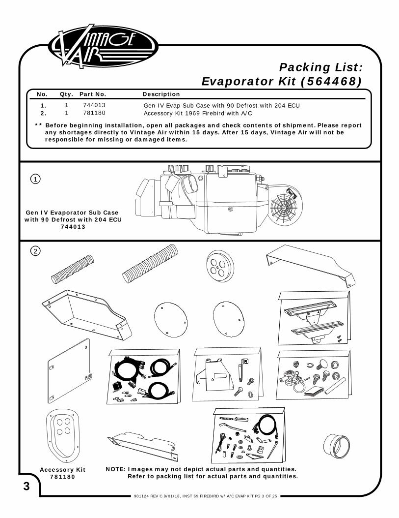
** Before beginning installation, open all packages and check contents of shipment. Please report any shortages directly to Vintage Air within 15 days. After 15 days, Vintage Air will not be responsible for missing or damaged items.
1.2.
11
744013781180
Gen IV Evap Sub Case with 90 Defrost with 204 ECUAccessory Kit 1969 Firebird with A/C
No. Qty. Part No. Description
Packing List:Evaporator Kit (564468)
NOTE: Images may not depict actual parts and quantities. Refer to packing list for actual parts and quantities.

4901124 REV C 8/01/18, INST 69 FIREBIRD w/ A/C EVAP KIT PG 4 OF 25
Important Notice—Please ReadFor Maximum System Performance, Vintage Air Recommends the Following:
New Vintage Air-supplied Sanden Compressor: No additional oil needed (Compressor is shipped with proper oil charge).All Other Compressors: Consult manufacturer (Some compressors are shipped dry and will need oil added).
NOTE: Vintage Air systems are designed to operate with R134a refrigerant only. Use of any other refrigerant could damage your A/C system and/or vehicle, and possibly cause a fire, in addition to potentially voiding the warranties of the A/C system and its components.
Refrigerant Capacities:Vintage Air System: 1.8 lbs. (1 lb., 12 oz.) of R134a, charged by weight with a quality charging station or scale. NOTE: Use of the proper type and amount of refrigerant is critical to system operation and performance.Other Systems: Consult manufacturer’s guidelines.
Lubricant Capacities:
Safety Switches
Service Info:Protect Your Investment: Prior to assembly, it is critical that the compressor, evaporator, A/C hoses and fittings, hardlines, condenser and receiver/drier remained capped. Removing caps prior to assembly will allow moisture, insects and debris into the components, possibly leading to reduced performance and/or premature failure of your A/C system. This is especially important with the receiver/drier. Additionally, when caps are removed for assembly, BE CAREFUL! Some components are shipped under pressure with dry nitrogen.Evacuate the System for 35-45 Minutes: Ensure that system components (Drier, compressor, evaporator and condenser) are at a temperature of at least 85° F. On a cool day, the components can be heated with a heat gun or by running the engine with the heater on before evacuating. Leak check and charge to specifications.
Your Vintage Air system is equipped with a binary pressure safety switch. A binary switch disengages the compressor clutch in cases of extreme low pressure conditions (Refrigerant Loss) or excessively high head pressure (406 PSI) to prevent compressor damage or hose rupture. A trinary switch combines Hi/Lo pressure protection with an electric fan operation signal at 254 PSI, and should be substituted for use with electric fans. Compressor safety switches are extremely important since an A/C system relies on refrigerant to circulate lubricant.
Bolts Passing Through Cowl and/or Firewall:To ensure a watertight seal between the passenger compartment and the vehicle exterior, for all bolts passing through the cowl and/or firewall, Vintage Air recommends coating the threads with silicone prior to installation.
Heater Hose (Not Included With This Kit):Heater hose may be purchased from Vintage Air (Part# 31800-VUD) or your local parts retailer. Routing and required length will vary based on installer preference.
5901124 REV C 8/01/18, INST 69 FIREBIRD w/ A/C EVAP KIT PG 5 OF 25
Important Wiring Notice—Please Read
Some Vehicles May Have Had Some or All of Their Radio Interference Capacitors Removed. There Should Be a Capacitor Found At Each of the Following Locations:
1. On the positive terminal of the ignition coil.2. If there is a generator, on the armature terminal of the generator.3. If there is a generator, on the battery terminal of the voltage regulator.
Most alternators have a capacitor installed internally to eliminate what is called “whining” as the engine is revved. If whining is heard in the radio, or just to be extra cautious, a radio interference capacitor can be added to the battery terminal of the alternator.
It is also important that the battery lead is in good shape and that the ground leads are not compromised. There should be a heavy ground from the battery to the engine block, and additional grounds to the body and chassis.
If these precautions are not observed, it is possible for voltage spikes to be present on the battery leads. These spikes come from ignition systems, charging systems, and from switching some of the vehicle’s other systems on and off. Modern computer-operated equipment can be sensitive to voltage spikes on the power leads, which can cause unexpected resets, strange behavior, and/or permanent damage.
Vintage Air strives to harden our products against these types of electrical noise, but there is a point where a vehicle’s electrical system can be degraded so much that nothing can help.
Radio interference capacitors should be available at most auto and truck parts suppliers. They typically are cylindrical in shape, a little over an inch long, a little over a half inch in diameter, and they have a single lead coming from one end of the cylinder with a terminal on the end of the wire, as well as a mounting clip which is screwed into a good ground on the vehicle. The specific value of the capacitance is not too significant in comparison to ignition capacitors that are matched with the coil to reduce pitting of the points.
Care must be taken, when installing the compressor lead, not to short it to ground. The compressor lead must not be connected to a condenser fan or to any other auxiliary device. Shorting to ground or connecting to a condenser fan or any other auxiliary device may damage wiring, the compressor relay, and/or cause a malfunction.
When installing ground leads on Gen IV systems, the blower control ground and ECU ground must be connected directly to the negative battery post.
For proper system operation, the heater control valve must be connected to the ECU.
•
•
•
6901124 REV C 8/01/18, INST 69 FIREBIRD w/ A/C EVAP KIT PG 6 OF 25
Condenser Assembly & Installation
Compressor & Brackets
Pulleys
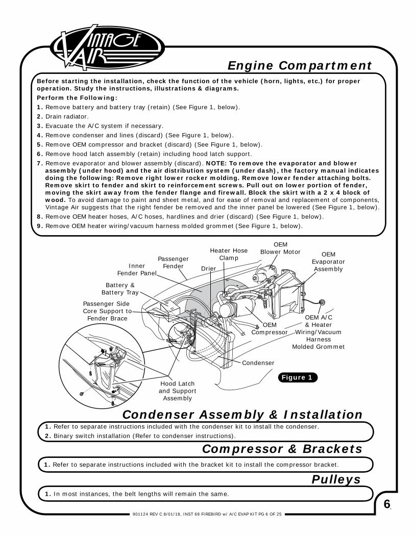
Engine CompartmentBefore starting the installation, check the function of the vehicle (horn, lights, etc.) for proper operation. Study the instructions, illustrations & diagrams.Perform the Following:1. Remove battery and battery tray (retain) (See Figure 1, below).2. Drain radiator.3. Evacuate the A/C system if necessary.4. Remove condenser and lines (discard) (See Figure 1, below).5. Remove OEM compressor and bracket (discard) (See Figure 1, below).6. Remove hood latch assembly (retain) including hood latch support.7. Remove evaporator and blower assembly (discard). NOTE: To remove the evaporator and blower assembly (under hood) and the air distribution system (under dash), the factory manual indicates doing the following: Remove right lower rocker molding. Remove lower fender attaching bolts. Remove skirt to fender and skirt to reinforcement screws. Pull out on lower portion of fender, moving the skirt away from the fender flange and firewall. Block the skirt with a 2 x 4 block of wood. To avoid damage to paint and sheet metal, and for ease of removal and replacement of components, Vintage Air suggests that the right fender be removed and the inner panel be lowered (See Figure 1, below).8. Remove OEM heater hoses, A/C hoses, hardlines and drier (discard) (See Figure 1, below).9. Remove OEM heater wiring/vacuum harness molded grommet (See Figure 1, below).
1. Refer to separate instructions included with the condenser kit to install the condenser.2. Binary switch installation (Refer to condenser instructions).
1. Refer to separate instructions included with the bracket kit to install the compressor bracket.
1. In most instances, the belt lengths will remain the same.
Battery &Battery Tray
Passenger Side Core Support to
Fender Brace
InnerFender Panel
PassengerFender Drier
Heater HoseClamp
Condenser
OEMCompressor
OEMEvaporatorAssembly
OEMBlower Motor
OEM A/C& Heater
Wiring/VacuumHarness
Molded Grommet
Hood Latchand Support
Assembly
Figure 1
7901124 REV C 8/01/18, INST 69 FIREBIRD w/ A/C EVAP KIT PG 7 OF 25
Astro Vent Door Assembly(Passenger & Driver Side)
OEM Glove Box Door
Radio
Ashtray
AshtraySlider Assembly
View From Inside Vehicle
OEM ControlPanel
Instrument PanelAssembly
SteeringColumn
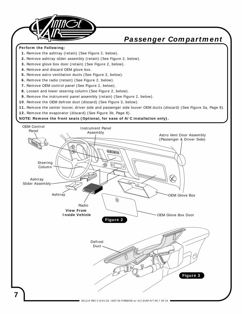
Passenger CompartmentPerform the Following: 1. Remove the ashtray (retain) (See Figure 2, below). 2. Remove ashtray slider assembly (retain) (See Figure 2, below). 3. Remove glove box door (retain) (See Figure 2, below). 4. Remove and discard OEM glove box. 5. Remove astro ventilation ducts (See Figure 2, below). 6. Remove the radio (retain) (See Figure 2, below). 7. Remove OEM control panel (See Figure 2, below). 8. Loosen and lower steering column (See Figure 2, below). 9. Remove the instrument panel assembly (retain) (See Figure 2, below).10. Remove the OEM defrost duct (discard) (See Figure 3, below).11. Remove the center louver, driver side and passenger side louver OEM ducts (discard) (See Figure 3a, Page 8).12. Remove the evaporator (discard) (See Figure 3b, Page 8).NOTE: Remove the front seats (Optional, for ease of A/C installation only).
OEM Glove Box
Figure 2
DefrostDuct
Figure 3
8901124 REV C 8/01/18, INST 69 FIREBIRD w/ A/C EVAP KIT PG 8 OF 25
Passenger Compartment (Cont.)
Fresh Air Door and Kick Panel Removal
Evaporator
Fresh AirDoor Assembly
Fresh AirDoor Assembly
OEMScrews
OEMScrewsOEM
Screws
Center Louver,Driver and
Passenger SideLouver OEM Ducts
Figure 3a
Figure 4 Figure 4a
Figure 3b
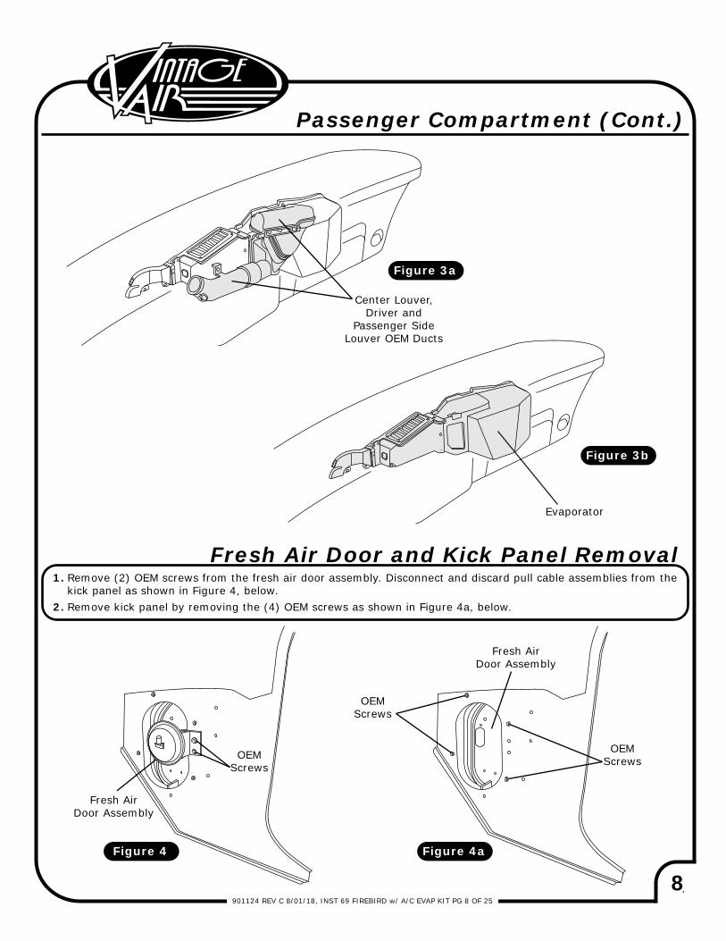
Remove (2) OEM screws from the fresh air door assembly. Disconnect and discard pull cable assemblies from thekick panel as shown in Figure 4, below.Remove kick panel by removing the (4) OEM screws as shown in Figure 4a, below.
1.
2.
9901124 REV C 8/01/18, INST 69 FIREBIRD w/ A/C EVAP KIT PG 9 OF 25
Figure 6
Figure 5
Passenger SideFresh Air Cover
640712
Passenger SideDefrost Duct626676-VCA
(2) #10 X 1/2” Hex Sheet Metal Screws
18247-VUB
OEMLouver
Passenger Side
HoseAdapter
49870-VCI
Driver SideDefrost Duct626676-VCA
Driver SideFresh Air Cover
640711
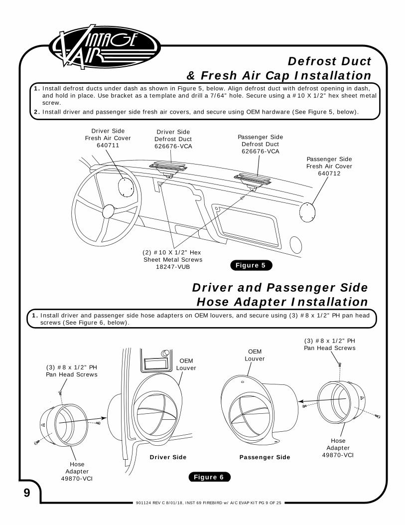
1. Install defrost ducts under dash as shown in Figure 5, below. Align defrost duct with defrost opening in dash, and hold in place. Use bracket as a template and drill a 7/64” hole. Secure using a #10 X 1/2” hex sheet metal screw.2. Install driver and passenger side fresh air covers, and secure using OEM hardware (See Figure 5, below).
Defrost Duct& Fresh Air Cap Installation
1. Install driver and passenger side hose adapters on OEM louvers, and secure using (3) #8 x 1/2” PH pan head screws (See Figure 6, below).
Driver and Passenger SideHose Adapter Installation
OEMLouver
Driver Side
(3) #8 x 1/2” PHPan Head Screws
(3) #8 x 1/2” PHPan Head Screws
HoseAdapter
49870-VCI
10901124 REV C 8/01/18, INST 69 FIREBIRD w/ A/C EVAP KIT PG 10 OF 25
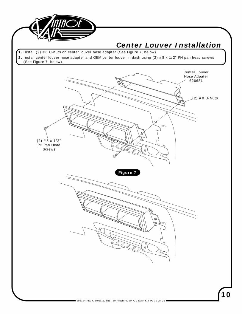
Center Louver Installation1. Install (2) #8 U-nuts on center louver hose adapter (See Figure 7, below). 2. Install center louver hose adapter and OEM center louver in dash using (2) #8 x 1/2” PH pan head screws (See Figure 7, below).
Figure 7
Center LouverHose Adpater
626681
(2) #8 U-Nuts
(2) #8 x 1/2”PH Pan Head
Screws
11901124 REV C 8/01/18, INST 69 FIREBIRD w/ A/C EVAP KIT PG 11 OF 25
1/4-20 X 1 ½”Bolt w/ Washer
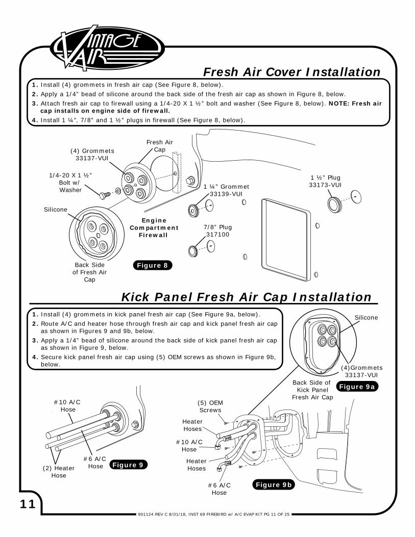
Fresh Air Cover Installation
Silicone
Fresh AirCap(4) Grommets
33137-VUI
Back Sideof Fresh Air
Cap
EngineCompartment
Firewall
Silicone
Back Side of Kick Panel
Fresh Air Cap
#10 A/C Hose
#6 A/C Hose(2) Heater
Hose
(4)Grommets33137-VUI
Figure 8
Figure 9b
Figure 9
Figure 9a
1 ½” Plug33173-VUI
7/8” Plug317100
1 ¼” Grommet33139-VUI
1. Install (4) grommets in fresh air cap (See Figure 8, below).2. Apply a 1/4” bead of silicone around the back side of the fresh air cap as shown in Figure 8, below.3. Attach fresh air cap to firewall using a 1/4-20 X 1 ½” bolt and washer (See Figure 8, below). NOTE: Fresh air cap installs on engine side of firewall.4. Install 1 ¼”, 7/8” and 1 ½” plugs in firewall (See Figure 8, below).
Kick Panel Fresh Air Cap Installation1. Install (4) grommets in kick panel fresh air cap (See Figure 9a, below).2. Route A/C and heater hose through fresh air cap and kick panel fresh air cap as shown in Figures 9 and 9b, below.3. Apply a 1/4” bead of silicone around the back side of kick panel fresh air cap as shown in Figure 9, below.4. Secure kick panel fresh air cap using (5) OEM screws as shown in Figure 9b, below.
(5) OEMScrews
#10 A/CHose
#6 A/CHose
HeaterHoses
HeaterHoses
12901124 REV C 8/01/18, INST 69 FIREBIRD w/ A/C EVAP KIT PG 12 OF 25
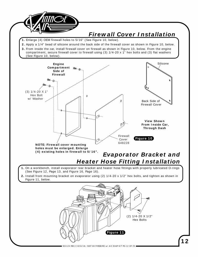
EngineCompartment
Side of Firewall
NOTE: Firewall cover mounting holes must be enlarged. Enlarge (4) existing holes in firewall to 5/16”.
View Shown From Inside Car, Through Dash
Figure 10
Back Side of Firewall Cover
Silicone
Evaporator Bracket andHeater Hose Fitting Installation
1. On a workbench, install evaporator rear bracket and heater hose fittings with properly lubricated O-rings (See Figure 12, Page 13, and Figure 16, Page 16).2. Install front mounting bracket on evaporator using (2) 1/4-20 x 1/2” hex bolts, and tighten as shown in Figure 11, below.
Firewall Cover Installation 1. Enlarge (4) OEM firewall holes to 5/16” (See Figure 10, below).2. Apply a 1/4” bead of silicone around the back side of the firewall cover as shown in Figure 10, below.3. From inside the car, install firewall cover on firewall as shown in Figure 10, below. From the engine compartment, secure firewall cover to firewall using (3) 1/4-20 x 1” hex bolts and (3) flat washers (See Figure 10, below).
(2) 1/4-20 X 1/2”Hex Bolts
Figure 11
(3) 1/4-20 X 1”Hex Bolt
w/ Washer
FirewallCover 648228
13901124 REV C 8/01/18, INST 69 FIREBIRD w/ A/C EVAP KIT PG 13 OF 25
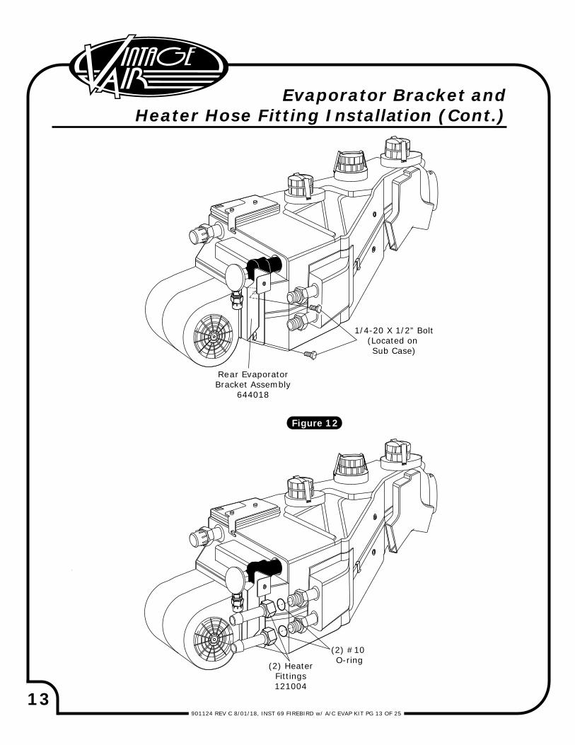
Rear EvaporatorBracket Assembly
644018
Evaporator Bracket andHeater Hose Fitting Installation (Cont.)
Figure 12
1/4-20 X 1/2” Bolt(Located on Sub Case)
(2) HeaterFittings121004
(2) #10 O-ring
14901124 REV C 8/01/18, INST 69 FIREBIRD w/ A/C EVAP KIT PG 14 OF 25
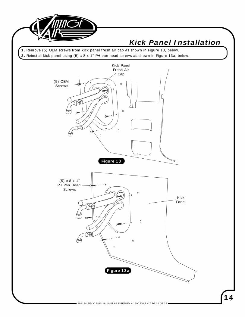
Kick Panel Installation1. Remove (5) OEM screws from kick panel fresh air cap as shown in Figure 13, below.2. Reinstall kick panel using (5) #8 x 1” PH pan head screws as shown in Figure 13a, below.
Figure 13a
Figure 13
(5) OEM Screws
Kick PanelFresh Air
Cap
(5) #8 x 1”PH Pan Head
Screws
KickPanel
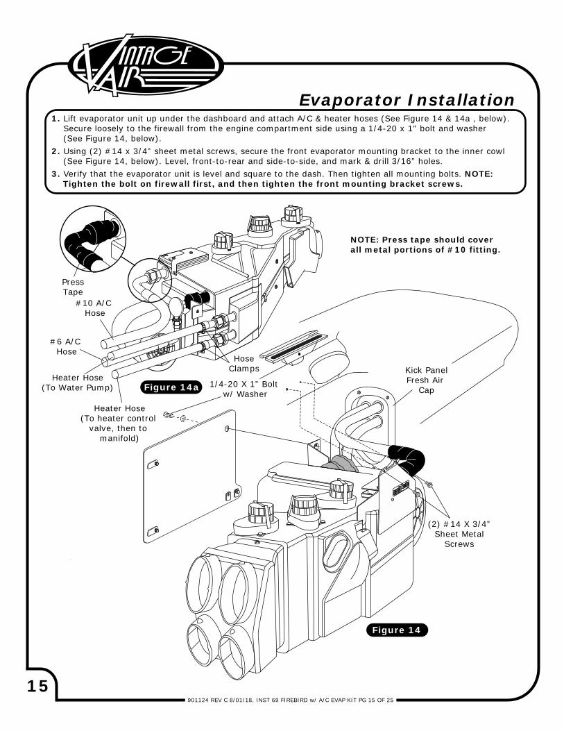
15901124 REV C 8/01/18, INST 69 FIREBIRD w/ A/C EVAP KIT PG 15 OF 25
Kick PanelFresh Air
Cap
(2) #14 X 3/4”Sheet Metal
Screws
1/4-20 X 1” Bolt w/ Washer
Evaporator Installation1. Lift evaporator unit up under the dashboard and attach A/C & heater hoses (See Figure 14 & 14a , below). Secure loosely to the firewall from the engine compartment side using a 1/4-20 x 1” bolt and washer (See Figure 14, below).2. Using (2) #14 x 3/4” sheet metal screws, secure the front evaporator mounting bracket to the inner cowl (See Figure 14, below). Level, front-to-rear and side-to-side, and mark & drill 3/16” holes.3. Verify that the evaporator unit is level and square to the dash. Then tighten all mounting bolts. NOTE: Tighten the bolt on firewall first, and then tighten the front mounting bracket screws.
#10 A/C Hose
#6 A/C Hose
PressTape
Heater Hose(To heater control
valve, then to manifold)
Heater Hose(To Water Pump) Figure 14a
Figure 14
HoseClamps
NOTE: Press tape should coverall metal portions of #10 fitting.
16901124 REV C 8/01/18, INST 69 FIREBIRD w/ A/C EVAP KIT PG 16 OF 25
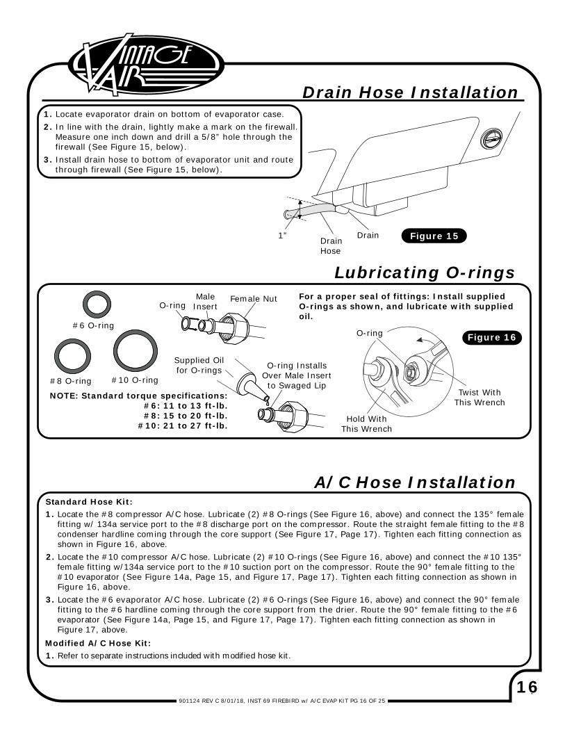
1. Locate the #8 compressor A/C hose. Lubricate (2) #8 O-rings (See Figure 16, above) and connect the 135° female fitting w/ 134a service port to the #8 discharge port on the compressor. Route the straight female fitting to the #8 condenser hardline coming through the core support (See Figure 17, Page 17). Tighten each fitting connection as shown in Figure 16, above.2. Locate the #10 compressor A/C hose. Lubricate (2) #10 O-rings (See Figure 16, above) and connect the #10 135° female fitting w/134a service port to the #10 suction port on the compressor. Route the 90° female fitting to the #10 evaporator (See Figure 14a, Page 15, and Figure 17, Page 17). Tighten each fitting connection as shown in Figure 16, above.3. Locate the #6 evaporator A/C hose. Lubricate (2) #6 O-rings (See Figure 16, above) and connect the 90° female fitting to the #6 hardline coming through the core support from the drier. Route the 90° female fitting to the #6 evaporator (See Figure 14a, Page 15, and Figure 17, Page 17). Tighten each fitting connection as shown in Figure 17, above.
A/C Hose InstallationStandard Hose Kit:
Modified A/C Hose Kit:1. Refer to separate instructions included with modified hose kit.
1. Locate evaporator drain on bottom of evaporator case.2. In line with the drain, lightly make a mark on the firewall. Measure one inch down and drill a 5/8” hole through the firewall (See Figure 15, below).3. Install drain hose to bottom of evaporator unit and route through firewall (See Figure 15, below).
Drain Hose Installation
1” DrainDrainHose
Figure 15
Figure 16
O-ring Installs Over Male Insert to Swaged Lip
O-ring#6 O-ring
#8 O-ring #10 O-ring
O-ring
Supplied Oil for O-rings
Male Insert
Female Nut
Hold With This Wrench
Twist With This Wrench
Lubricating O-rings For a proper seal of fittings: Install supplied O-rings as shown, and lubricate with supplied oil.
NOTE: Standard torque specifications:#6: 11 to 13 ft-lb.#8: 15 to 20 ft-lb.
#10: 21 to 27 ft-lb.
17901124 REV C 8/01/18, INST 69 FIREBIRD w/ A/C EVAP PG 17 OF 25
A/
C &
Hea
ter
Ho
se R
ou
tin
g
#6
Drier
/Con
d H
ardl
ine
3536
8-VCG
#8
Dis
char
geH
ose
0960
84
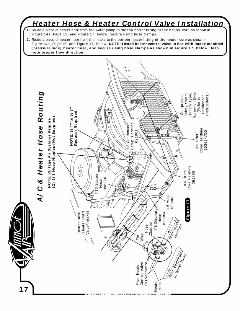
Heater Hose & Heater Control Valve Installation1. Route a piece of heater hose from the water pump to the top heater fitting of the heater core as shown in Figure 14a, Page 15, and Figure 17, below. Secure using hose clamps.2. Route a piece of heater hose from the intake to the bottom heater fitting of the heater core as shown in Figure 14a, Page 15, and Figure 17, below. NOTE: Install heater control valve in line with intake manifold (pressure side) heater hose, and secure using hose clamps as shown in Figure 17, below. Also note proper flow direction.
Tie
Wra
p
Com
pres
sor
Saf
ety
Sw
itch
(Bin
ary
Type
)Scr
ew-o
n D
rier
(Ref
er t
oCon
dens
erIn
stru
ctio
ns)
Fig
ure
17
#6
Hos
e09
6080
Hos
eCla
mps
From
Eva
pora
tor
to W
ater
Pum
p
From
Int
ake
Man
ifold
NO
TE:
Vin
tag
e A
ir S
yste
ms
Req
uir
e(2
) 5
/8
Hos
e N
ipp
les
(Not
Su
pp
lied
)
NO
TE:
3/
4”
to 5
/8
” R
edu
cer
Req
uir
ed
From
Hea
ter
Con
trol
Val
veto
Eva
pora
tor
#6
Drier
/Cor
e H
ardl
ine
0919
60
Hea
ter
Hos
e(H
eate
r Cnt
rlVa
lve/
Inta
ke)
#10
Suc
tion
Hos
e09
6076
Hea
ter
Hos
e
#8
Con
dens
er/
Com
p. H
ardl
ine
0919
61
18901124 REV C 8/01/18, INST 69 FIREBIRD w/ A/C EVAP KIT PG 18 OF 25
Glove BoxTop
49068-VCI
Glove BoxBottom
49067-VCI
OEM Screws
OEM Screws
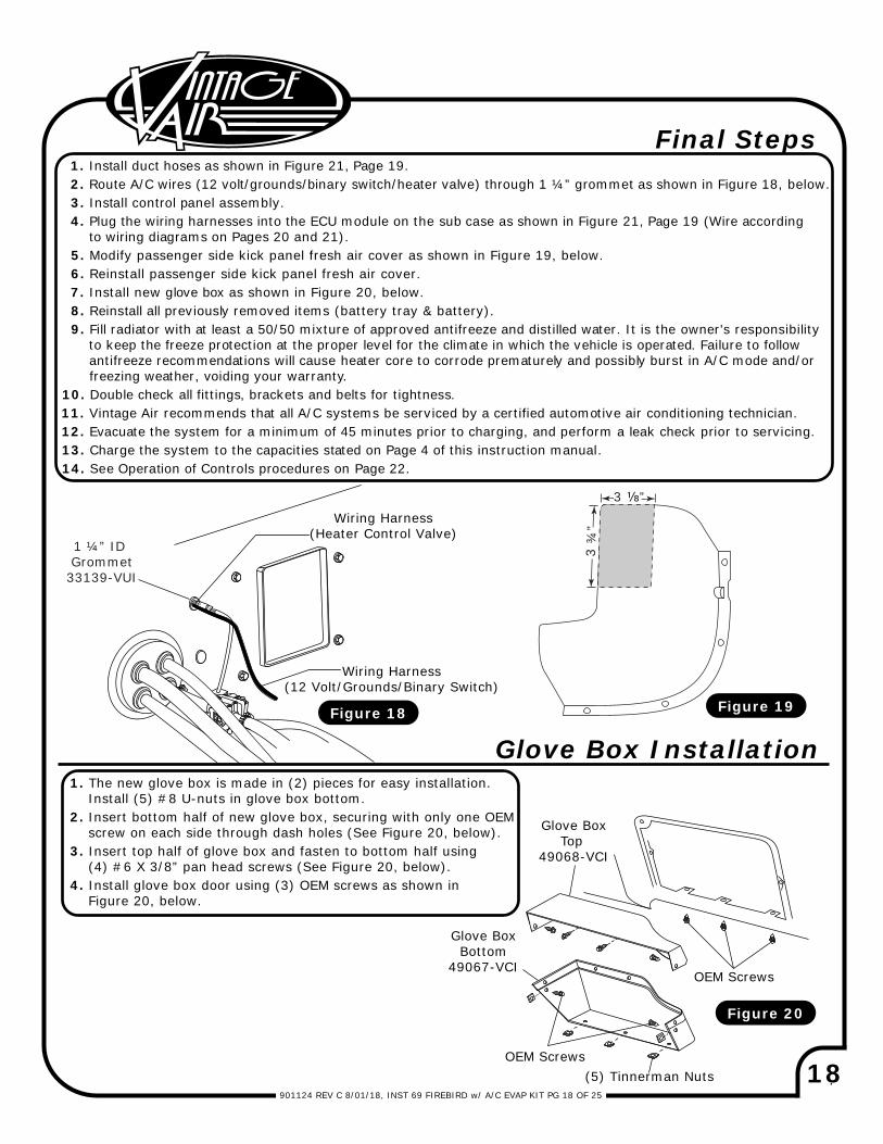
Final Steps 1. Install duct hoses as shown in Figure 21, Page 19. 2. Route A/C wires (12 volt/grounds/binary switch/heater valve) through 1 ¼” grommet as shown in Figure 18, below. 3. Install control panel assembly. 4. Plug the wiring harnesses into the ECU module on the sub case as shown in Figure 21, Page 19 (Wire according to wiring diagrams on Pages 20 and 21). 5. Modify passenger side kick panel fresh air cover as shown in Figure 19, below. 6. Reinstall passenger side kick panel fresh air cover. 7. Install new glove box as shown in Figure 20, below. 8. Reinstall all previously removed items (battery tray & battery). 9. Fill radiator with at least a 50/50 mixture of approved antifreeze and distilled water. It is the owner's responsibility to keep the freeze protection at the proper level for the climate in which the vehicle is operated. Failure to follow antifreeze recommendations will cause heater core to corrode prematurely and possibly burst in A/C mode and/or freezing weather, voiding your warranty.10. Double check all fittings, brackets and belts for tightness.11. Vintage Air recommends that all A/C systems be serviced by a certified automotive air conditioning technician. 12. Evacuate the system for a minimum of 45 minutes prior to charging, and perform a leak check prior to servicing. 13. Charge the system to the capacities stated on Page 4 of this instruction manual. 14. See Operation of Controls procedures on Page 22.
Glove Box Installation1. The new glove box is made in (2) pieces for easy installation. Install (5) #8 U-nuts in glove box bottom.2. Insert bottom half of new glove box, securing with only one OEM screw on each side through dash holes (See Figure 20, below).3. Insert top half of glove box and fasten to bottom half using (4) #6 X 3/8” pan head screws (See Figure 20, below).4. Install glove box door using (3) OEM screws as shown in Figure 20, below.
Figure 18
Figure 20
Figure 19
(5) Tinnerman Nuts
1 ¼” ID Grommet33139-VUI
3 ⅛”
3 ¾
”
Wiring Harness(12 Volt/Grounds/Binary Switch)
Wiring Harness(Heater Control Valve)
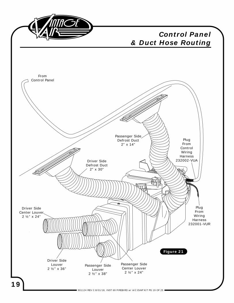
19901124 REV C 8/01/18, INST 69 FIREBIRD w/ A/C EVAP KIT PG 19 OF 25
FromControl Panel
Control Panel& Duct Hose Routing
Driver SideDefrost Duct
2” x 30”
Passenger SideLouver
2 ½” x 38”
Driver SideLouver
2 ½” x 36”
Driver SideCenter Louver
2 ½” x 24”
Passenger SideCenter Louver
2 ½” x 24”
Figure 21
PlugFromWiring
Harness232001-VUR
PlugFrom
ControlWiring
Harness232002-VUA
Passenger SideDefrost Duct
2” x 14”
20901124 REV C 8/01/18, INST 69 FIREBIRD w/ A/C EVAP KIT PG 20 OF 25
WHT/GRN
WHT/YELWHT/RED
RED
WHTBACKLIGHT NEG
FAN WIPER
MODE WIPER
TEMP WIPER
5V-SW
GND
BACKLIGHT POS
AC ANNUNCIATOR
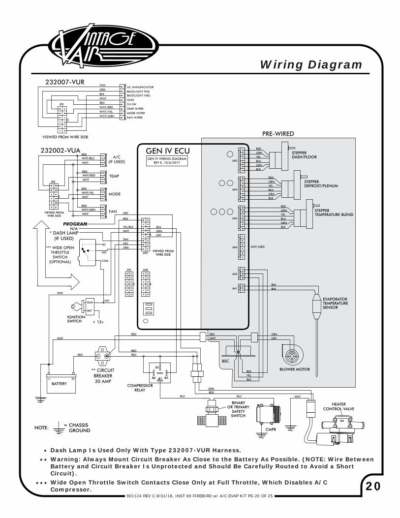
PRE-WIRED
GEN IV WIRING DIAGRAMREV E, 10/6/2017
GEN IV ECU
PROGRAM
Wiring Diagram
TEMP
MODE
FAN
A/C(IF USED)
232007-VUR
232002-VUA
** CIRCUITBREAKER30 AMP
*** WIDE OPENTHROTTLESWITCH
(OPTIONAL)
* DASH LAMP(IF USED)
Dash Lamp Is Used Only With Type 232007-VUR Harness.Warning: Always Mount Circuit Breaker As Close to the Battery As Possible. (NOTE: Wire BetweenBattery and Circuit Breaker Is Unprotected and Should Be Carefully Routed to Avoid a ShortCircuit).Wide Open Throttle Switch Contacts Close Only at Full Throttle, Which Disables A/C Compressor.
JF8
BLK
ORA
TAN
VIEWED FROM WIRE SIDE
* **
***
HEATERCONTROL VALVE
21901124 REV C 8/01/18, INST 69 FIREBIRD w/ A/C EVAP KIT PG 21 OF 25
RED
CIRCUIT BREAKER30 AMP
+
+
-
BLACK
REDWHITE
RED
CHASSIS GROUND
A/CCOMPRESSOR
RELAY
Ignition Switch:
Dash Light:
NOTE: MOUNT RELAYIN DESIRED LOCATION
UNDER DASH
GREEN
FIREWALL
BLUE
BLUE
RED &
WHITE
VIOLET
(IGNITION HOTTERMINAL)
IGNITION SWITCH
DASH BACK LIGHT+0-12vTAN
GRAY
BLUE
WHITE
WHITE
REDRED
WHITE
COMPRESSOR
BATTERY
NOTE: CONNECT WHITEWIRES DIRECTLY TO
(-) BATTERY TERMINAL
BATRUN
12V
RED GREEN
RED
RED
BLUE
LATCH
BLACK
BINARYSAFETYSWITCH
YELLOW
ORANGE
WIRING HARNESS
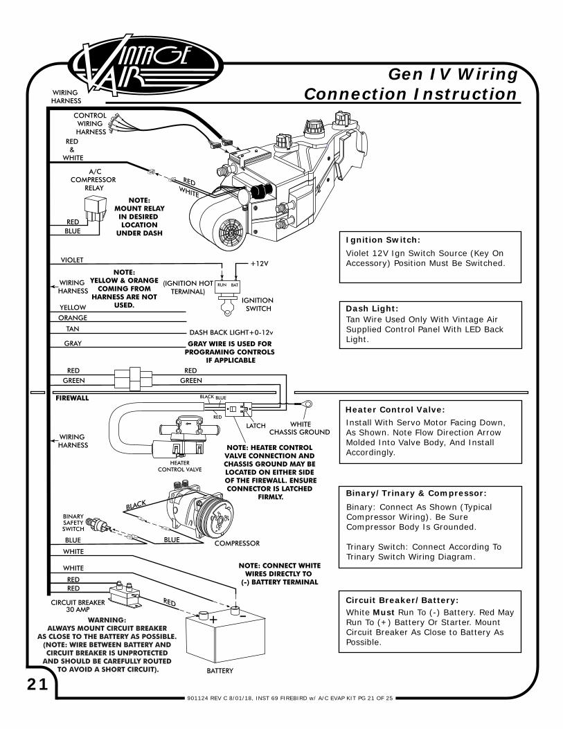
Violet 12V Ign Switch Source (Key On Accessory) Position Must Be Switched.
Tan Wire Used Only With Vintage Air Supplied Control Panel With LED Back Light.
Binary: Connect As Shown (Typical Compressor Wiring). Be Sure Compressor Body Is Grounded.
Trinary Switch: Connect According To Trinary Switch Wiring Diagram.
Install With Servo Motor Facing Down, As Shown. Note Flow Direction Arrow Molded Into Valve Body, And Install Accordingly.
White Must Run To (-) Battery. Red May Run To (+) Battery Or Starter. Mount Circuit Breaker As Close to Battery As Possible.
Heater Control Valve:
Binary/Trinary & Compressor:
Circuit Breaker/Battery:
CONTROL WIRING HARNESS
NOTE: YELLOW & ORANGE
COMING FROM HARNESS ARE NOT
USED.
WIRING HARNESS
GRAY WIRE IS USED FOR PROGRAMING CONTROLS
IF APPLICABLE
WIRING HARNESS
Gen IV Wiring Connection Instruction
HEATERCONTROL VALVE
WARNING: ALWAYS MOUNT CIRCUIT BREAKER
AS CLOSE TO THE BATTERY AS POSSIBLE. (NOTE: WIRE BETWEEN BATTERY AND CIRCUIT BREAKER IS UNPROTECTED
AND SHOULD BE CAREFULLY ROUTED TO AVOID A SHORT CIRCUIT).
NOTE: HEATER CONTROL VALVE CONNECTION AND CHASSIS GROUND MAY BE LOCATED ON EITHER SIDE OF THE FIREWALL. ENSURECONNECTOR IS LATCHED
FIRMLY.
22901124 REV C 8/01/18, INST 69 FIREBIRD w/ A/C EVAP KIT PG 22 OF 25
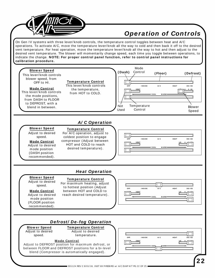
Operation of Controls
Adjust to desiredspeed.
Blower SpeedAdjust to desired
speed.
Adjust to desiredmode position (DASH position recommended).
Adjust to desiredspeed.
Adjust to DEFROST position for maximum defrost, or between FLOOR and DEFROST positions for a bi-level
blend (Compressor is automatically engaged).
Adjust to desired temperature.
For A/C operation, adjust tocoldest position to engage
compressor (Adjust between HOT and COLD to reachdesired temperature).
A/C Operation
Heat Operation
Defrost/De-fog Operation
On Gen IV systems with three lever/knob controls, the temperature control toggles between heat and A/C operations. To activate A/C, move the temperature lever/knob all the way to cold and then back it off to the desired vent temperature. For heat operation, move the temperature lever/knob all the way to hot and then adjust to the desired vent temperature. The blower will momentarily change speed, each time you toggle between operations, to indicate the change. NOTE: For proper control panel function, refer to control panel instructions for calibration procedure.
Blower Speed
Blower Speed
This lever/knob controlsblower speed, from
OFF to HI.
This lever/knob controls the mode positions,from DASH to FLOORto DEFROST, with a blend in between.
This lever/knob controlsthe temperature,
from HOT to COLD.
Blower Speed
Mode Control
Temperature Control
Temperature Control
Temperature Control
Temperature Control
Mode Control
Mode Control
Mode Control
For maximum heating, adjust to hottest position (Adjust between HOT and COLD to reach desired temperature).Adjust to desired
mode position(FLOOR position recommended).
OFF INSIDE A/C HEAT
WARM
LO HI
DE-ICE
COOL
NORM VENT
Not Used
(Defrost)(Floor)(Dash)Mode
Control
Blower Speed
TemperatureControl
OFF INSIDE A/C HEAT
WARM
LO HI
DE-ICE
COOL
NORM VENT
OFF INSIDE A/C HEAT
WARM
LO HI
DE-ICE
COOL
NORM VENT
OFF INSIDE A/C HEAT
WARM
LO HI
DE-ICE
COOL
NORM VENT
23901124 REV C 8/01/18, INST 69 FIREBIRD w/ A/C EVAP PG 23 OF 25
Sym
pto
m
Con
dit
ion
Ch
ecks
A
ctio
ns
Not
es
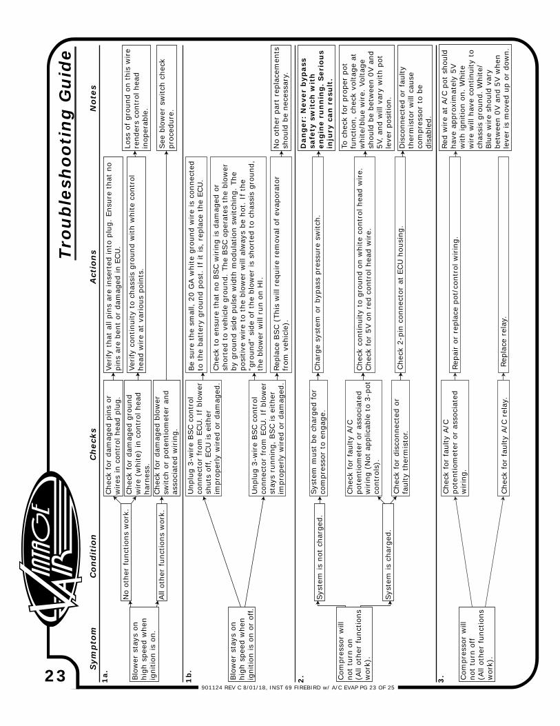
Blo
wer
sta
ys o
n hi
gh s
peed
whe
n ig
nitio
n is
on.
1a.
No
othe
r fu
nctio
ns w
ork.
Che
ck f
or d
amag
ed p
ins
or
wires
in c
ontr
ol h
ead
plug
.Ve
rify
tha
t al
l pin
s ar
e in
sert
ed in
to p
lug.
Ens
ure
that
no
pins
are
ben
t or
dam
aged
in E
CU
.Che
ck f
or d
amag
ed g
roun
d w
ire
(whi
te)
in c
ontr
ol h
ead
harn
ess.
Verify
con
tinui
ty t
o ch
assi
s gr
ound
with
whi
te c
ontr
ol
head
wire
at v
ario
us p
oint
s.
Loss
of gr
ound
on
this
wire
rend
ers
cont
rol h
ead
inop
erab
le.
All
othe
r fu
nctio
ns w
ork.
Che
ck f
or d
amag
ed b
low
er
switc
h or
pot
entio
met
er a
nd
asso
ciat
ed w
irin
g.
Blo
wer
sta
ys o
n hi
gh s
peed
whe
n ig
nitio
n is
on
or o
ff.
Unp
lug
3-w
ire
BSC c
ontr
ol
conn
ecto
r fr
om E
CU
. If
blo
wer
sh
uts
off,
ECU
is e
ither
im
prop
erly
wired
or
dam
aged
.
Be
sure
the
sm
all,
20 G
A w
hite
gro
und
wire
is c
onne
cted
to
the
bat
tery
gro
und
post
. If
it is
, re
plac
e th
e EC
U.
Unp
lug
3-w
ire
BSC c
ontr
ol
conn
ecto
r fr
om E
CU
. If
blo
wer
st
ays
runn
ing,
BSC is
eith
er
impr
oper
ly w
ired
or
dam
aged
.
Che
ck t
o en
sure
tha
t no
BSC w
irin
g is
dam
aged
or
shor
ted
to v
ehic
le g
roun
d. T
he B
SC o
pera
tes
the
blow
er
by g
roun
d si
de p
ulse
wid
th m
odul
atio
n sw
itchi
ng.
The
posi
tive
wire
to t
he b
low
er w
ill a
lway
s be
hot
. If
the
“g
roun
d” s
ide
of t
he b
low
er is
sho
rted
to
chas
sis
grou
nd,
the
blow
er w
ill r
un o
n H
I.
Repl
ace
BSC (
This
will
req
uire
rem
oval
of ev
apor
ator
fr
om v
ehic
le).
No
othe
r pa
rt r
epla
cem
ents
sh
ould
be
nece
ssar
y.
Com
pres
sor
will
no
t tu
rn o
n (A
ll ot
her
func
tions
w
ork)
.
2.
Syst
em is
not
cha
rged
.Sy
stem
mus
t be
cha
rged
for
co
mpr
esso
r to
eng
age.
Cha
rge
syst
em o
r by
pass
pre
ssur
e sw
itch.
Dan
ger
: N
ever
byp
ass
safe
ty s
wit
ch w
ith
en
gin
e ru
nn
ing
. S
erio
us
inju
ry c
an r
esu
lt.
Syst
em is
cha
rged
.
1b
.
Trou
ble
shoo
tin
g G
uid
e
Che
ck f
or f
aulty
A/C
po
tent
iom
eter
or
asso
ciat
ed
wirin
g (N
ot a
pplic
able
to
3-po
t co
ntro
ls).
Che
ck f
or d
isco
nnec
ted
or
faul
ty t
herm
isto
r.
Che
ck c
ontin
uity
to
grou
nd o
n w
hite
con
trol
hea
d w
ire.
Che
ck f
or 5
V o
n re
d co
ntro
l hea
d w
ire.
Che
ck 2
-pin
con
nect
or a
t EC
U h
ousi
ng.
To c
heck
for
pro
per
pot
func
tion,
che
ck v
olta
ge a
t w
hite
/blu
e w
ire.
Vol
tage
sh
ould
be
betw
een
0V a
nd
5V,
and
will
var
y w
ith p
ot
leve
r po
sitio
n.
Dis
conn
ecte
d or
fau
lty
ther
mis
tor
will
cau
se
com
pres
sor
to b
e di
sabl
ed.
Red
wire
at A
/C p
ot s
houl
d ha
ve a
ppro
xim
atel
y 5V
w
ith ig
nitio
n on
. W
hite
w
ire
will
hav
e co
ntin
uity
to
chas
sis
grou
nd.
Whi
te/
Blu
e w
ire
shou
ld v
ary
betw
een
0V a
nd 5
V w
hen
leve
r is
mov
ed u
p or
dow
n.
3. Com
pres
sor
will
no
t tu
rn o
ff
(All
othe
r fu
nctio
ns
wor
k).
Che
ck f
or f
aulty
A/C
po
tent
iom
eter
or
asso
ciat
ed
wirin
g.
Che
ck f
or f
aulty
A/C
rel
ay.
Repa
ir o
r re
plac
e po
t/co
ntro
l wirin
g.
Repl
ace
rela
y.
See
blo
wer
sw
itch
chec
k pr
oced
ure.
24901124 REV C 8/01/18, INST 69 FIREBIRD w/ A/C EVAP KIT PG 24 OF 25
Sym
pto
m
Con
dit
ion
Ch
ecks
A
ctio
ns
Not
es
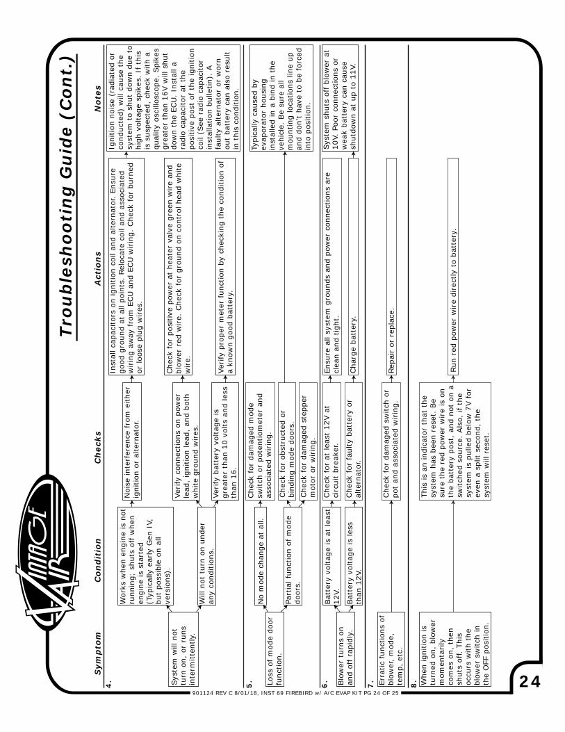
Syst
em w
ill n
ot
turn
on,
or
runs
in
term
itten
tly.
4.
Wor
ks w
hen
engi
ne is
not
runn
ing;
shu
ts o
ff w
hen
engi
ne is
sta
rted
(T
ypic
ally
ear
ly G
en I
V,
but
poss
ible
on
all
vers
ions
).
Noi
se in
terf
eren
ce f
rom
eith
er
igni
tion
or a
ltern
ator
.
Inst
all c
apac
itors
on
igni
tion
coil
and
alte
rnat
or.
Ensu
re
good
gro
und
at a
ll po
ints
. Re
loca
te c
oil a
nd a
ssoc
iate
d w
irin
g aw
ay f
rom
ECU
and
ECU
wirin
g. C
heck
for
bur
ned
or lo
ose
plug
wires
.
Verify
con
nect
ions
on
pow
er
lead
, ig
nitio
n le
ad,
and
both
whi
te g
roun
d w
ires
.
Verify
pro
per
met
er f
unct
ion
by c
heck
ing
the
cond
ition
of
a kn
own
good
bat
tery
.
Igni
tion
nois
e (r
adia
ted
orco
nduc
ted)
will
cau
se t
he
syst
em t
o sh
ut d
own
due
tohi
gh v
olta
ge s
pike
s. I
f th
isis
sus
pect
ed,
chec
k w
ith a
qu
ality
osc
illos
cope
. Spi
kes
grea
ter
than
16V
will
shu
t do
wn
the
ECU
. In
stal
l a
radi
o ca
paci
tor
at t
he
posi
tive
post
of th
e ig
nitio
nco
il (S
ee r
adio
cap
acito
r in
stal
latio
n bu
lletin
). A
fa
ulty
alte
rnat
or o
r w
orn
out
batt
ery
can
also
res
ult
in t
his
cond
ition
.
Will
not
tur
n on
und
er
any
cond
ition
s.Ve
rify
bat
tery
vol
tage
is
grea
ter
than
10
volts
and
less
than
16.
Loss
of m
ode
door
fu
nctio
n.
No
mod
e ch
ange
at
all.
Che
ck f
or d
amag
ed m
ode
switc
h or
pot
entio
met
er a
nd
asso
ciat
ed w
irin
g.
Part
ial f
unct
ion
of m
ode
door
s.
Typi
cally
cau
sed
by
evap
orat
or h
ousi
ng
inst
alle
d in
a b
ind
in t
he
vehi
cle.
Be
sure
all
mou
ntin
g lo
catio
ns li
ne u
p an
d do
n’t
have
to
be for
ced
into
pos
ition
.
Blo
wer
tur
ns o
n an
d of
f ra
pidl
y.
6.
Bat
tery
vol
tage
is a
t le
ast
12V.
Che
ck f
or a
t le
ast
12V a
t ci
rcui
t br
eake
r.En
sure
all
syst
em g
roun
ds a
nd p
ower
con
nect
ions
are
cl
ean
and
tight
.
Bat
tery
vol
tage
is le
ss
than
12V
.
5.
Trou
ble
shoo
tin
g G
uid
e (C
ont.
)
Che
ck f
or f
aulty
bat
tery
or
alte
rnat
or.
Cha
rge
batt
ery.
Syst
em s
huts
off b
low
er a
t 10
V. P
oor
conn
ectio
ns o
r w
eak
batt
ery
can
caus
e sh
utdo
wn
at u
p to
11V
.
7. Whe
n ig
nitio
n is
tu
rned
on,
blo
wer
m
omen
tarily
co
mes
on,
the
n sh
uts
off.
This
oc
curs
with
the
bl
ower
sw
itch
in
the
OFF
pos
ition
.
This
is a
n in
dica
tor
that
the
sy
stem
has
bee
n re
set.
Be
sure
the
red
pow
er w
ire
is o
nth
e ba
tter
y po
st,
and
not
on a
sw
itche
d so
urce
. Als
o, if
the
sy
stem
is p
ulle
d be
low
7V f
orev
en a
spl
it se
cond
, th
e sy
stem
will
res
et.
Run
red
pow
er w
ire
dire
ctly
to
batt
ery.
Che
ck f
or p
ositi
ve p
ower
at
heat
er v
alve
gre
en w
ire
and
blow
er r
ed w
ire.
Che
ck f
or g
roun
d on
con
trol
hea
d w
hite
w
ire.
Che
ck f
or o
bstr
ucte
d or
bi
ndin
g m
ode
door
s.Che
ck f
or d
amag
ed s
tepp
er
mot
or o
r w
irin
g.
Erra
tic fun
ctio
ns o
fbl
ower
, m
ode,
te
mp,
etc
.
Che
ck f
or d
amag
ed s
witc
h or
po
t an
d as
soci
ated
wirin
g.Re
pair o
r re
plac
e.
8.

901124 REV C 8/01/18, INST 69 FIREBIRD w/ A/C EVAP KIT PG 25 OF 25
1
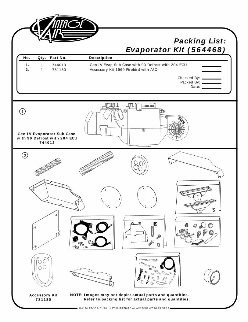
1.2.
11
744013781180
Gen IV Evap Sub Case with 90 Defrost with 204 ECUAccessory Kit 1969 Firebird with A/C
No. Qty. Part No. Description
Packing List:Evaporator Kit (564468)
Checked By:Packed By:
Date:
Gen IV Evaporator Sub Case with 90 Defrost with 204 ECU
744013
2
Accessory Kit781180
NOTE: Images may not depict actual parts and quantities. Refer to packing list for actual parts and quantities.