1970-1981 gm “f” body rear bolt-in 4-link installation
TRANSCRIPT

1 812-482-2932
InstallationInstructions
Recommended Tools
www.ridetech.com
Table of contentsPage 2-3.......... Included ComponentsPage 4............. Hardware ListPage 5-7.......... DisassemblyPage 8-9.......... Front Lower Bar & Subframe Mount InstallationPage 10-11...... Subframe InstallationPage 12-14...... Upper Bulkhead InstallationPage 15........... Using TemplatePage 16-17...... Cutting Upper Bar HolesPage 17........... Installing Lower 4 Link BarsPage 18 .......... Installing Lower Axle MountsPage 19 .......... Attaching Lower 4 Link Bars to DifferentialPage 20 .......... Setting Pinion AnglePage 21 .......... Upper 4 Link Bar InstallationPage 22-23...... Upper Bar Tab InstallationPage 24-25...... Installing Upper 4 Link BarsPage 25........... Shock Crossmember InstallationPage 26........... Installing Lower Shock MountPage 26-27...... Installing ShockWaves/CoilOversPage 28-30...... Rear Seat Modifi cation
Part # 11177150 -1970-1981 GM “F” Body Rear Bolt-in 4 Link
1970-1981 GM “F” Body Rear Bolt-in 4-Link
Installation Instructions
REV4 8/14/20

2www.ridetech.com
InstallationInstructions
Major Components .....In the box
Item # Part # Description QTY1 90002785 Subframe Rail - Driver 1
2 90002786 Subframe Rail - Passenger 1
3 90002787 Rear Frame Bushing 4
4 90002788 Lower Bar Front Frame Bracket - Driver 1
5 90002789 Lower Bar Front Frame Bracket - Passenger 1
6 90002790 Lower Bar Front Frame Bracket Inner Reinforcing Plate - Front 2
7 90002791 Lower Bar Front Frame Bracket Inner Reinforcing Plate - Top 2
8 90002792 Lower Bar Front Frame Bracket Inner Reinforcing Plate - Rear 2
9 90002802 Front Frame Bracket Spacer 2
10 90002793 Upper 4 Link Bar Front Bulkhead 1
11 90002794 Front Bulkhead Reinforcing Plate 1
12 90002795 Upper Bar Adjustment Washer 4
13 90002796 Rear Shock Crossmember 1
14 90002797 Upper 4 Link Bar (9.250” center to center) 2
15 90002798 Lower 4 Link Bar (24.500” center to center) 2
16 90001318 Complete R-Joint - Installed in Upper Bars 2
17 70013442 Weld-On Lower Bar/Shock Mount 2
18 70013439 Upper Bar Tab 4
19 70013441 Axle Tab Rear Brace 2
20 70002825 Lower Shock Stud 2
21 90001624 Aluminum Lower Shock Mount 2
22 90002067 Lower Shock Spacers 4
23 70013554 Seat Frame Wire 1
24 70013618 Upper 4 Link Bar Rubber Boot 2
70013655 2” Steel Loop, Rounded 10
70013656 5/8” Hog Rings 12
70013657 7/8” Hog Rings 12
70013334 R-Joint Spacers 16
70013675 Safety Wire 6
70010694 Bar Tab Setting Jig 2
99752004 3/4”-16 Jam Nut - Installed on R-Joint Rod En2s 2
Template Upper Bar Hole Cutting Template 1
99372009 3/8”-16 U-Nuts - .090 -.20 Panel Thickness 6

3 812-482-2932
InstallationInstructions
Major Components .....In the box
7
6
8
5
4
2
1
14
16
9
23
10
11
2412
13
1518
19
3
20
21
17
New R-Joints will be quite stiff (75-90 in/lbs breakaway torque) until they “break in” after a few miles of use. After the break in period they will move much more freely. Because the composite bearing race contains self lubricating ingredients, no additional lubrication is needed or desired. Any additional lubrication will only serve to attract more dirt and debris to the R-Joint and actually shorten its life.

4www.ridetech.com
InstallationInstructions
Hardware List .....In the box (Kit# 99010072)
QTY Part Number Description
LOWER BAR/SUBFRAME MOUNT
16 99371005 3/8”-16 x 1 1/4” Hex Bolt
12 99372001 3/8-16” Nylok Nut
30 99373002 3/8” SAE Flat washer
2 99371007 3/8”-16 x 1 1/2” Hex Bolt
6 99372009 3/8”-16 U-Nut
SUBFRAME MOUNTING
2 99621024 5/8”-11 x 4 1/2” Gr. 8 Bolt
8 99623010 5/8” SAE Flat Washer Gr. 8
2 99621032 5/8”-11 x 4 1/2” Gr. 8 Bolt
4 99622008 5/8”-11 Thin Nylok Nut
UPPER BAR BULKHEAD
6 99371005 3/8”-16 x 1 1/4” Hex Bolt
6 99372001 3/8-16” Nylok Nut
12 99373002 3/8” SAE Flat washer
2 99501062 1/2”-13 x 1 1/4” Hex Bolt
2 99502001 1/2”-13 Nylok Nut
4 99503014 1/2” SAE Flat Washer
UPPER SHOCK CROSSMEMBER
4 99371052 3/8”-16 x 2 1/4” Hex Bolt
4 99372001 3/8-16” Nylok Nut
8 99373002 3/8” SAE Flat washer
BAR SETTING JIG
2 99371001 3/8”-16 x 3/4” Hex Bolt
2 99372004 3/8”-16 Hex Nut
The Hardware Kit contains bags to help aid in selecting the correct hardware for the component being installed. The hardware list shows how the hardware is bagged.
Getting Started.........Congratulations on your purchase of the Ridetech Rear 4-link System. This system has been designed to give your Camaro excellent handling along with a lifetime of enjoyment. This kit replaces the Leaf Springs, this allows the 4-Link to locate the rearend and the CoilOvers/ShockWaves to support the car. This allows each to be optimized for the best performance.
Note: These system is designed for use with the Ridetech Shockwaves or CoilOvers and the MuscleBar swaybar. The factory shocks and springs will not fi t this setup.
QTY Part Number Description
UPPER 4 LINK BARS
2 99621004 5/8”x 3” Gr. 8 Bolt
2 99621005 5/8”x 3 1/2” Gr. 8 Bolt
4 99622006 5/18”-18 Thin Nylok Nut
8 99623010 5/8” SAE Flat Washer Gr. 8
LOWER 4 LINK BARS
2 99621004 5/8”x 3” Gr. 8 Bolt
2 99621003 5/8”x 2 3/4” Gr. 8 Bolt
4 99622006 5/18”-18 Thin Nylok Nut
6 99623010 5/8” SAE Flat Washer Gr. 8
UPPER SHOCK MOUNTING
2 99621022 5/8”-18 x 2 1/2” Gr. 8 Bolt
2 99622006 5/18”-18 Thin Nylok Nut
4 99623010 5/8” SAE Flat Washer Gr. 8
LOWER SHOCK MOUNT
2 99501019 1/2”-13 x 1 1/4” Hex Bolt
2 99501046 1/2”-13 x 1 3/4” Hex Bolt
4 99502001 1/2”-13 Nylok Nut
4 99503001 1/2” SAE Flat Washer
SHOCK STUD
2 99432002 7/16”-20 Nylok Nut
2 99433002 7/16” SAE Flat Washer
2 99623004 5/8” SAE Flat Washer

5 812-482-2932
InstallationInstructions
Disassembly1. Raise the vehicle to a safe and comfortable working height. Use jack stands to support the vehicle with the suspension hanging freely.
2. Support the axle and remove the leaf springs, shocks, and tail pipes. If your car is equipped with a rear sway bar, it will also need to be removed. Disconnect the emergency brake cables and brake line from the differential. Plug or cap the rear brake line to keep debris out of the line and to keep from losing all the brake fl uid from the rear line. Remove the rear differential, it will make it easier to cut the OEM leaf spring mounts off. Refer to the factory service manual for proper disassembly procedures. The back seat of the car will also need removed for installation of the some of the brackets. If the rear brake line gets detached, you will need to bleed the rear brakes. You may need to redo the brake lines that are on the differential.
The following steps show the removal of brackets, these can vary depending on the year of the car. Some years do NOT have some of the brackets shown. If your car doesn’t have the particular bracket shown in a step, skip to the next step.
3.3. Disconnect the emergency brake cables from the main cable at the adjuster. It is located under the driver side rear foot well. After it is removed, disconnect the cables from the connector that joins the rear cables together. Set the hardware and connector aside, you will need them for reassembly.
4. Remove the retaining clips that hold the emergency brake cable in place. 4.

6www.ridetech.com
InstallationInstructions
Disassembly5. Remove the bracket on the outside of the frame that holds the emergency cable in place. This will allow the cable to be pulled out of the car. You do NOT need to remove the cables from the differential.
6. Remove the emergency brake cable bracket from the frame. You can do this by drilling out the spot welds or cutting it fl ush with the frame rails. We used a sawzall to remove them.
7. Cut the corner braces off that are located above the axle where the frame rail drops down. Depending on the year of your car, it may not be equipped with these braces.These can be removed by drilling the spot welds or cutting them of fl ush with the tabs.
5.
6.
7.

7 812-482-2932
InstallationInstructions
Disassembly8. If your car has this style of exhaust bracket behind the axle, they will need to be cut off. Again, this can be done by drilling the rivets or cutting off fl ush with the tabs. The early cars have a different style of mount that doesn’t need to be cut off.
9. Remove the U-joint straps from the yoke. Disconnect the driveshaft from the rear differential. It is a good idea to wrap masking tape around the end of the driveshaft to help keep the u-joint caps in place.
10. Unbolt the pinion snubber and remove it.
8.
9.
10.

8www.ridetech.com
InstallationInstructions
Front Lower Bar & Subframe Mount Installation11. Remove the rear shackle bushings from the frame on both sides of the car. Clean the hole to remove any debris that may be in the hole.
12. The front OEM leaf spring mount is attached to the body using u-nuts. New 3/18”-16 U-Nuts are supplied in the kit. Install the U-Nuts in place of the OEM u-nuts.
13. Insert a 3/8”-16 x 1 1/2” Hex Bolt in the rear hole of the Lower Bar/Subframe Mount. This needs to be inserted from the bottom with the threads sticking up. Install the Aluminum Spacer on the bolt.
12.
13.
11.

9 812-482-2932
InstallationInstructions
Front Lower Bar & Subframe Mount Installation14. Hold the Bolt/Spacer in place by hand. Flip the bracket over with the bolt pointing up. Hold the Assembly in place lining up the holes with the U-nuts. The 3/8”-16 x 1 1/2” Bolt installed in the previous step will thread into the U-nut that is in the frame rail. Thread it in while holding the mount in place. The bar mount area will fi t into the OEM leaf spring area. The part of the Mount with the Bung welded to it will nest up into the fl oor pan of the car, similar to Image 13. Install a 3/8” Flat Washer on each of (2) 3/8”-16 x 1 1/4” Bolts and thread them into the remaining to OEM mounting locations with U-Nuts in them. DO NOT TIGHTEN THE (3) BOLTS. Repeat on the other side.
REMOVE THE REAR SEAT BEFORE DOING THE NEXT STEPS. YOU WILL BE DRILLING THROUGH THE HUMP IN FRONT OF THE BOTTOM SEAT LATCH, PULL THE CARPET AND SOUND DEADENER UP TO EXPOSE THE AREA.
15. Use a jack, or something similar, to push up on the inside of the Lower Mount. This will help nest the mount up into the fl oor pan. While pushing up on the inside of the mount, drill the top hole through the fl oor pan using a 3/8” drill bit. Also drill up through the center of the Bung. After you drill through the center of the bung, drill the hole to 5/8” from the top side. The hole through the fl at plate will remain 3/8”
16. The kit includes (3) pairs of Backer Plates with (3) different hole confi gurations. The Top Plate only has a 3/8” & 5/8” hole. This is the Plate you will be installing at this time. Align the hole in the Top Plate with the hole you just drilled. Install a 3/8” Flat Washer on a 3/8”-16 x 1 1/4” Hex bolt and insert it through the hole in the Top Plate, Floor Pan, and Lower Mount. Install a 3/8” Flat Washer and 3/8”-16 Nylok Nut on the threads sticking through the Lower Mount. Tighten this bolt and the (3) already threaded into the U-Nuts.
14.
15.
16.
DRILL 5/8”
DRILLCENTER

10www.ridetech.com
InstallationInstructions
Front Lower Bar & Subframe Mount Installation17. Drill the remaining 5 holes with a 3/8” drill bit. Install a 3/8” Flat Washer on each of (5) 3/8”-16 x 1 1/4” Hex Bolts. Line the 3 Hole Backer up with the front 3 drilled holes. Install a Bolt/Washer in each hole. Install a 3/8” Flat Washer & 3/8”-16 Nylok Nut on each bolt sticking through the Lower Bracket. Line the 2 Hole Backer up with the rear 2 drilled holes. Install a Bolt/Washer in each hole. Install a 3/8” Flat Washer & 3/8”-16 Nylok Nut on each bolt sticking through the Lower Bracket. Tighten all hardware to 45ftlbs. NOTE: The 5/8” bolt will be installed later.
18. Install the Aluminum Rear Frame Bushings in the rear shackle bushing holes. They are installed like the OEM shackle bushings, 1 into each side. The fi t can vary due to the condition of the holes on your car. If the bushings are tight, you can pull them in by inserting the 5/8”-16 x 4 1/2” bolt through both of them, install a 5/18”-16 Nut and tightening the bolt/nut until the bushings are fully seated in the frame hole. Remove the bolt/nut after seating the bushings. Install the bushings in the driver and passenger side.
19. Attached the rear of the subframes to the newly installed Rear Frame Bushings. The kit includes a Driver and Passenger Subframe. Each one will be installed with the tabs to the inside of the car. Install a 5/8” Flat Washer on a 5/8”-11 x 4 1/2” bolt and insert it through the tabs and bushings with the threads to the inside of the car. With the bolt/washer installed, install a 5/8” Flat Washer and 5/8-11 Thin Nylok Nut on the threads sticking through. DO NOT TIGHTEN.
17.
18.
19.

11 812-482-2932
InstallationInstructions
Subframe Installation20. The front of the Subframes will swing up and engage onto the Bung on the Front Lower Mount as seen in Image 21. Later cars have the brake line mounted on the drivers rear frame rail, this will need to be clearanced to allow the Subframe to swing up in place. Image 20 shows this mount.
21. Swing the Subframe up in place and engage it with the Bung on the Lower Mount. Push the end of the Subframe up to seat it on the bung. Install a 5/8” Flat Washer on a 5/8”-11 x 4 1/2” FULLY THREADED Hex Bolt. Thread the Bolt/Washer in through the center hole of the Bung. Do this for both Subframes. Torque the front and rear 5/8” bolts to 100 ftlbs. After torquing the Hardware, install a 5/8” Flat Washer and 5/8”-11 Thin Nylok Nut on the Threads of the 5/8”-11 x 4 1/2” Bolt that is sticking up through the fl oor off the car. This is located by the top backing plate.
THE SEAT BACK AND DIVIDER WILL NEED TO BE REMOVED FOR THE FOLLOWING STEPS.
22. Center punch ONLY the lower hole of the forward tabs of the Subframes.
23. Drill the center punched hole with a 3/8” drill bit. ONLY DRILL THE LOWER HOLE IN THE FORWARD TABS.
20.
21.
22. 23.

12www.ridetech.com
InstallationInstructions
Upper Bar Bulkhead Installation24. Use a die grinder, or similar tool, to slot the lower hole of the forward tabs. Use the Tab as a template for slotting the hole.
25. Set the Upper Bar Bulkhead in place over the driveshaft tunnel lining up the 2 lower holes with the 2 slots you just created.
Note: You will notice we used the bulkhead as a template to trim the rear seat divider. You can do this now or after the bulkhead is installed.
26. Install a 3/8” Flat Washer on each of (2) 3/8”-16 x 1 1/4” Hex Bolts. Insert a bolt/washer into the lined up lower holes. Install a 3/8” Flat Washer & 3/8”-16 Nylok Nut on bolts where they come through the forward tab of the subframe. Lightly tighten the bolts.
24.
25.
26.
13 812-482-2932
InstallationInstructions
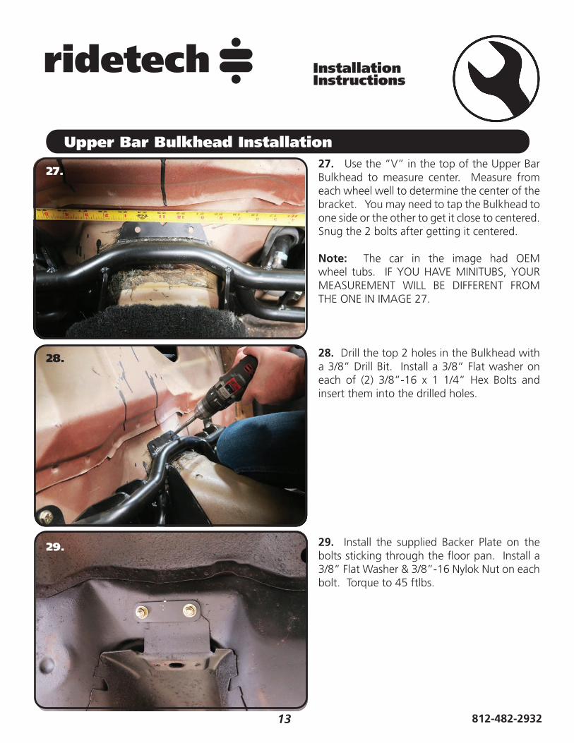
Upper Bar Bulkhead Installation27. Use the “V” in the top of the Upper Bar Bulkhead to measure center. Measure from each wheel well to determine the center of the bracket. You may need to tap the Bulkhead to one side or the other to get it close to centered. Snug the 2 bolts after getting it centered.
Note: The car in the image had OEM wheel tubs. IF YOU HAVE MINITUBS, YOUR MEASUREMENT WILL BE DIFFERENT FROM THE ONE IN IMAGE 27.
28. Drill the top 2 holes in the Bulkhead with a 3/8” Drill Bit. Install a 3/8” Flat washer on each of (2) 3/8”-16 x 1 1/4” Hex Bolts and insert them into the drilled holes.
29. Install the supplied Backer Plate on the bolts sticking through the fl oor pan. Install a 3/8” Flat Washer & 3/8”-16 Nylok Nut on each bolt. Torque to 45 ftlbs.
27.
28.
29.

14www.ridetech.com
InstallationInstructions
Upper Bar Bulkhead Installation30. The Bulkhead has a tab the goes forward on each side of the driveshaft tunnel, in the end of each tab is a 1/2” hole. Using the Bulkhead holes as a template, drill the driveshaft tunnel with a 1/2” drill bit. Do this for the forward hole in each tab. Insert the supplied 1/2”-13 x 1 1/4” bolt in each drilled hole with a 1/2” washer on the top side and bottom side, follow the bottom washer with a 1/2”-13 Nylok Nut. Torque the 2 bolts/nuts to 110 ftlbs.
31. Drill the top 2 outer holes in the Bulkhead with a 3/8” Drill Bit. Install a 3/8” Flat washer on each of (2) 3/8”-16 x 1 1/4” Hex Bolts and insert them into the drilled holes.
32. Removed the lower nut and washers from the Forward Subframe Tabs.
30.
31.
32.

15 812-482-2932
InstallationInstructions
Using the Template33. Cut the 4 Outer Slots out of the template. Slide it over the 4 bolts sticking through the Forward tabs. Make sure the ARROW POINTS UP!
34. Install a 3/8” Flat Washer and 3/8”-16 Nylok Nut on the bolts sticking through the Forward Tabs and Template. Tighten the nuts fi nger tight to help hold the template in place.
35. Use the Notch in the top of the Template to center it. Measure out from the frame rail on each side to fi nd center. We found it easier to put a mark on the car, then align the template notch with the mark.
33.
34.
35.

16www.ridetech.com
InstallationInstructions
Upper Bar Hole Cutting36. Use the “ “ marks in the template to center punch the car body. Center punch all (4) “ “ marks.
37. Drill the center punched spots with a 3” hole saw.
38. Use a straight edge to draw a reference line from circle to circle. You will be cutting out the rest to make an obround. Image 38 shows both sides cut out. After connecting the holes, remove any burrs from the edge of the holes. Install a 3/8” Flat Washer & 3/8”-16 Nylok Nut on each of the 4 bolts sticking through the Forward Tabs that were installed previously. DO NOT TIGHTEN THESE 4 BOLTS AT THIS TIME, THEY WILL GET TIGHTENED AFTER THE SHOCK CROSSMEMBER IS INSTALLED.
36.
37.
38.
17 812-482-2932
InstallationInstructions
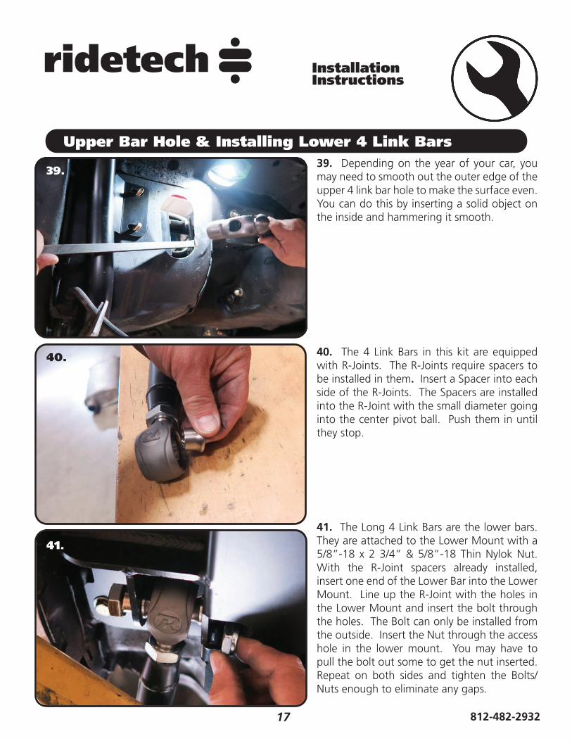
Upper Bar Hole & Installing Lower 4 Link Bars39. Depending on the year of your car, you may need to smooth out the outer edge of the upper 4 link bar hole to make the surface even. You can do this by inserting a solid object on the inside and hammering it smooth.
40. The 4 Link Bars in this kit are equipped with R-Joints. The R-Joints require spacers to be installed in them. Insert a Spacer into each side of the R-Joints. The Spacers are installed into the R-Joint with the small diameter going into the center pivot ball. Push them in until they stop.
41. The Long 4 Link Bars are the lower bars. They are attached to the Lower Mount with a 5/8”-18 x 2 3/4” & 5/8”-18 Thin Nylok Nut. With the R-Joint spacers already installed, insert one end of the Lower Bar into the Lower Mount. Line up the R-Joint with the holes in the Lower Mount and insert the bolt through the holes. The Bolt can only be installed from the outside. Insert the Nut through the access hole in the lower mount. You may have to pull the bolt out some to get the nut inserted. Repeat on both sides and tighten the Bolts/Nuts enough to eliminate any gaps.
39.
40.
41.

18www.ridetech.com
InstallationInstructions
42. The Lower Axle Mounts need to be welded to the rear differential before placing it in the car. The Lower Axle Mounts need to be parallel to the fl at surface of the center section. On a 10/12 bolt, it is the surface the rear cover bolts to. On a 9”, it’s the surface the center section bolts to. The axle mounts need to be installed at 40” center to center and centered on the differential. Image 42 shows a side view of a 10/12 bolt and 9” illustrating the surface we used as a reference to place the Lower Mount. It is best done on a fl at surface. We start by placing the differential on jack stands. We use a digital angle fi nder to get the vertical surface, shown in Image 42, straight up and down.
43. The Lower Axle Mounts need to be 40” center to center and centered on the differential. Start by establishing a common measurement point on each side of the axle to get a width measurement, Measurement “A”. You will need this to get the “B” Measurement to use as a reference when positioning the lower mounts. Once the width measurement “A” is established, subtract 40 from that measurement. Take the remainder of A - 40 and divide by 2. The remainder will be your “B” measurement that will be used on both sides. Using the “B” measurement, measure from the location that was used to establish your width and put a mark on the axle tube. Do this for both sides. To check your self, measure from mark to mark to see if it is 40”. The CENTER of the lower mounts will be placed at the mark on each side of the differential with the rear surface parallel with vertical surface shown in Image 42.
Formula: A - 40 = X X/2 = B
44. Place the mounts using Steps 42 & 43. Tack weld the brackets in place and verify their location. Lay 1” welds on the inside and outside of the lower mounts. Skip around from one side to the other to avoid overheating the tube.
42..
43.
Installing Lower Axle Mounts
PARALLEL
PARALLEL
10/12 BOLT
9” FORD
9” FORD
10/12 BOLT
40”
40”
B B
B B
FRONT VIEW
REAR VIEW
A
A

19 812-482-2932
InstallationInstructions
AFTER THE LOWER MOUNTS HAVE COOLED, REPOSITION THE REAR DIFFERENTIAL UNDER THE CAR.45. Verify that the Spacers are installed in the lower bars rear R-Joints. The Spacers are installed into the R-Joint with the small diameter going into the center pivot ball. Push them in until they stop.
46. Insert the Lower Bar R-Joint into the Lower Axle Bracket. Line the through hole of the R-Joint with the MIDDLE set of holes of the Axle Bracket. Install a 5/8” Flat Washer on to a 5/8”-18 x 3” Hex Bolt, insert into the lined up holes. Install a 5/8” Flat Washer followed by a 5/8”-18 Thin Jam Nylok Nut. Repeat on both sides and tighten the Bolts/Nuts enough to eliminate any gaps..
47. One helpful trick to help maintain ride height and pinion angle while positioning the differential is to put a spacer between the axle and the outside of the frame as shown in Image 47. This spacer should be 5 1/4” tall giving the Shockwave an eye-to-eye measurement of approximately 14 1/2”. When measuring the axle center you can measure off of the frame rails. We also use a plum bob off the quarter panels to double check the axle center. Refer to Page 20 on Setting the Pinion Angle.
45.
46.
47.
Attaching 4 Link Bars to Differential

20www.ridetech.com
InstallationInstructions
Setting Pinion Angle
READ PAGES 20-23 ON SETTING PINION ANGLES, UPPER BAR TAB JIG INSTALLATION, & SETTING RIDE HEIGHT.
How do you set the pinion angle? On a single-piece shaft you want to set it up where a line drawn through the center of the engine crankshaft or output shaft of the transmission and a line drawn through the center of the pinion are parallel to each other but not the same line.
Your transmission angle should be around 3 degrees down in the rear. If it is more or less than 3 degrees, you might want to consider changing it. Too little angle on the transmission reduces the amount of oil getting to the rear bushing. Too much transmission angle will increase the working angles of the u-joints which will increase the wear. With the transmission at 3 degrees down in the rear, you will want to set the pinion 3 degrees up in the front.
A simple way to do this is to place a digital angle fi nder or dial level on the front face of the lower engine pulley or harmonic balancer. This will give you a reading that is 90 degrees to the crank or output shaft unless you have real problems with your balancer. At the other end, you can place the same level or angle fi nder against the front face of the pinion yoke that is also at 90 degrees to the centerline. If you rotate the yoke up or down so both angles match, you have perfect alignment.
Road testing will tell you if you have it right. If you accelerate and you get or increase a vibration, then the pinion yoke is too HIGH. Rotate it downward in small increments of a degree or two until the problem goes away. If you get or increase a vibration when decelerating, then the pinion yoke is too LOW. Rotate it upward to correct it.

21 812-482-2932
InstallationInstructions
Upper 4 Link Bar Installation
48.
48. The Upper Bar Bulkhead is designed with adjustable Anti Squat. Anti Squat reduces the amount the rear suspension squats on acceleration. Anti Squat is measured in a percentage, the higher the percentage of anti squat the less the rear of the car squats. Reducing the rear squat keeps the rear suspension from compressing as much therefor reducing the amount the front suspension extends. This will help keep the suspension geometry in it’s optimized range. Anti squat uses the mechanics of the rear suspension to reduce squat rather than the shocks and springs. It uses the same mechanics to help put weight to the rear tires during acceleration. Several factors effect the amount of anti squat a car needs; horsepower, tires, vehicle weight, and track surface are some of the main ones. You can use the different settings in this suspension to help dial in your car’s handling. Keep in mind, the higher the rear squat percentage the less effective the rear tires will be under hard braking for corner entry. We control the Anti squat percentage by raising and lowering the front of the upper control arm. The centered position is approximately 60% Anti Squat. We have found this to be a good starting point.
INSIDE
OUTSIDE
MORE LESS
FRONT
STANDARDAPPROXIMATELY 60%
The Adjustment Washers supplied in the kit are octagon shaped with an offset hole. Due to the design of the Bulkhead and clearances, the standard centered position requires the Adjustment Washers to be ran offset of each other. This will make sense when you go to install them. Illustration 48 shows how the Adjustment Washers should be positioned with the Bolt running through the Washers, Bulkhead, and R-Joint. The Bulkhead has an Arced Slot for the bolt to run up and down in. This Arc helps keep the Pinion Angle when you adjust the Anti Squat. The Upper Bar Bulkhead has tabs above and below the Washers to keep them in position. Tightening the Bolt/Nut locks them in place.

22www.ridetech.com
InstallationInstructions
Installing Axle Tabs49. To simplify the upper tab installation, tack weld the assemblies together. The Upper Tab Assemblies are a mirror image of each other, Image 49 shows the Driver Assembly. The (4) Tabs are identical. Start by putting a Tab on each side of the Setting Jig, 1 long side down, 1 long side up. Set the Tabs on a fl at surface, the outer edges will be parallel with each other.
50. Set the Backer on the Tabs with the curved side toward the bolt. The fl at side of the Backer needs to be positioned 1/4”-3/8 up from the bottom on the short side of the tabs. Center the Backer side to side and tack weld it in place. Repeat this on the other set of tabs making a mirror image of the fi rst. Get both sets tacked together.
51. Use Illustration 48 on Page 21 as a reference for installing the Indexing Washers. Install the Washers with the Setting Jig in the MIDDLE POSITION. The Outer Washer is installed with the hole forward. The Inner Washer is installed with the hole to the rear. The Setting Jig is attached to the Bulkhead using a 5/8”-18 x 3 1/2” Hex Bolt & 5/8”-18 Thin Nylok Nut with a 5/8” Flat Washer on each side.
50.
49.
51.

23 812-482-2932
InstallationInstructions
Upper Bar Installation Jig• This jig has been supplied to aid in the installation of the upper 4 link bar. It can be temporarily used
to properly align, locate and weld the tabs onto the axle. It will also ensure that the mounting bolts are parallel to the ground.
• Follow the diagram below to set the jig to the same length as the upper bar, use the 3/8” x 3/4” bolt and nuts to set the length.
• Position the axle at ride height. Center the axle left to right between the quarter panels. Set pinion angle.
• Bolt one end of the jig to the cradle using a 5/8” x 3 1/2” bolt.• Using another 5/8” x 3” bolt, fasten the axle tab assemblies to the other end. There should be a driver
and passenger assembly.• Swing the bar down letting the tabs rest onto the axle. Trim the brackets as necessary to minimize the
gap to be welded. • Check pinion angle, ride height and axle center. Tack-weld the tab assemblies in place on the axle.• Remove jig and install upper bar. • Repeat this process for the other side.• Recheck pinion angle, ride height and axle center. (Sound familiar?)• After the tabs have been tack welded on both sides, remove the setting jig. Let the axle drop down for
better access to the tabs. Lay 1” welds on the inside and outside of the tabs. Skip around from one side to the other to avoid overheating the tube.
Upper Bar Tab Installation Jig
1
8
6
7
3
4
5
6
5
2
Item# Description1 Upper Bar
2 3/4”-16 Jam Nut
3 Heim End
4 Alignment Jig
5 Aluminum Spacer
6 5/8” x 2 3/4” Bolt
7 3/8”-16 Nut
8 3/8”-16 x 3/4” Bolt
INSIDE OUTSIDE

24www.ridetech.com
InstallationInstructions
52. Verify the Spacers are installed in the R-Joints of the Upper Bars. Insert the Upper Bar through the hole cut previously. The R-Joint will insert into the Bulkhead aligning the though hole with the slots in the Bulkhead.
53. Use Illustration 50 on Page 23 as a reference for installing the Indexing Washers. Install the Washers with the upper bar in the MIDDLE POSITION. The Outer Washer is installed with the hole forward. The Inner Washer is installed with the hole to the rear. The R-Joint is attached to the Bulkhead using a 5/8”-18 x 3 1/2” Hex Bolt & 5/8”-18 Thin Nylok Nut with a 5/8” Flat Washer on each side. . Repeat on the other Bar. Torque the hardware to 75 ftlbs.
54. Slip the Rubber Boots over the Upper 4 Link Bars. Insert them into the cut holes. They install like a rubber grommet, they have a groove around the outside edge to nest the sheet metal into.
52.
53.
54.
Installing Upper 4 Link Bars

25 812-482-2932
InstallationInstructions
Installing Upper Bars & Shock Crossmember55. Verify the Spacers are installed in the R-Joints of the Upper Bars. Insert the R-Joint into the upper bar mount of the rear differential. Install a 5/8” Flat Washer on to a 5/8”-16 x 3” Hex Bolt. Line up the holes in the axle tabs with the through hole of the R-Joint, insert the bolt/washer from the OUTSIDE with the threads pointing inward. Install a 5/8” Flat Washer followed by a 5/8”-18 Thin Jam Nylok Nut. Repeat on both sides and tighten the Bolts/Nuts enough to eliminate any gaps.
56. Insert the Shock Crossmember into the tabs on the Subframe. It is installed with the Swaybar Mounts to the REAR of the car. There are (2) mounting holes on each side that line up with the slots in the Subframe Mounts.
57. Install a 3/8” Flat Washer on each of (4) 3/8”-16 x 2 1/4” Hex Bolts. Install a Bolt/Washer in each of the (4) mounting holes. With the Bolts installed, install a 3/8” Flat Washer and 3/8”-16 Nylok Nut on each of them. Torque to 45 ftlbs. ALSO TORQUE THE 4 BOLTS TO 45 FTLBS THAT WERE LEFT LOSE IN STEP 38.
IF YOUR ALSO INSTALLING THE REAR MUSCLEBAR, INSTALL IT BEFORE INSTALLING THE SHOCKWAVES/COILOVERS.
55.
56.
57.

26www.ridetech.com
InstallationInstructions
Installing Lower Shock Mount & CoilOvers/ShockWaves58. The Lower Shock Mount attaches with (1) 1/2”-13 x 1 1/4” Hex Bolt, (1) 1/2”-13 x 1 3/4” Hex Bolt, & (2) 1/2” Flat Washer, & (2) 1/2”-13 Nylok Nuts. The Lower Mount gets attached to the 2nd and 3rd hole up from the bottom of the Axle Mount. When the Shock Mount is installed correctly, the bottom of the Lower Shock Mount is 1/8” above the bottom of the Axle Mount. Insert the Bolts through the Aluminum Shock Mount with the 1 1/4” long bolt in the top bolt, 1 3/4” in the bottom hole. Insert the bolts through the Axle Mount and install the Flat Washers & Nylok Nuts on the Threads sticking through. Repeat on both sides and torque the Bolts/Nuts to 75 ftlbs.
59. Installing the Shock Stud into the Lower Mount. Install a 5/8” Flat Washer onto the 5/8”-18 threads of the shock stud. Apply Red Loctite to the 5/8” threads of the stud. Thread the Shock Stud into the threaded hole of the Lower Mount. Repeat on both sides and torque the Shock Stud to 65-75 ftlbs.
60. Ridetech CoilOvers or ShockWaves require a spacer on each side of the bearing. The Upper Crossmember uses a 5/8” ID spacer that is 3/8” long (90002042). The overall width with a spacer on each side will be 1 1/4”. The small side of the spacer goes towards shock bearing.
58.
59.
60.

27 812-482-2932
InstallationInstructions
Installing CoilOvers/ShockWaves61. Insert the Shock with the 5/8” ID Spacers into the Shock Crossmember. Line up the holes in the crossmember with the spacers and shock bearing. Install a 5/8” Flat Washer on to a 5/8”-18 x 2 1/2” Hex Bolt, insert into the lined up holes. Install a 5/8” Flat Washer followed by a 5/8”-18 Thin Jam Nylok Nut. Torque to 75 ftlbs.
62. The Shock Stud requires spacers that are .400” long (90002067). Install a 5/8” ID 90002067 spacer (Small side towards shock body) onto the lower Shock Stud. Slide the bottom of the Shock onto the Stud. Install a second 5/8” ID 90002067 Spacer onto the Stud (small side towards shock). You may need to jack the rearend up to Slide the Shock onto the Stud.
63. Install the 7/16” Flat washer and 7/16” Nylok nut. Tighten the upper and lower shock bolts. Torque the Upper Bolt to 75 ftlbs and the Lower Nut to 40 ftlbs. The designed ride height of the CoilOver/Shockwave is 14 1/2” center to center.
61.
62.
63.

28www.ridetech.com
InstallationInstructions
Rear Seat Modifi cations64. The rear seat frame will need to be modifi ed to clear the bulkhead. A new Frame Wire is included to help stiffen the seat. Safety Wire is included to wire the Frame Wire to the existing seat frame. Image 64 has circles around the area that will need to be safety wired. You will also notice that part of the OEM seat frame has been cut out, we will show you where to cut it.
Note: The Frame Wire and safety wire is all Stainless, it does not need to be coated.
65. The Frame Wire needs to be inserted under the middle wire, right about the fi rst LONG horizontal frame wire. It will lay on top or beside of other frame wires.
66. The kit includes (6) long pieces of Safety Wire. Cut the long pieces in about 3” pieces. We will start in the location close to the attaching loop. Start by wrapping a 3” piece of Safety Wire around the Frame Wire and seat frame close to the 1st bend of the frame wire. Twist it a little to hold it in place.
64.
65.
66.

29 812-482-2932
InstallationInstructions
67. We used Safety Wire Pliers to twist the wires, but you can use regular Pliers or Vise-Grips to twist it. Grab the wire approximately 1” from the frame wire and twist it until it is tight. If you twist it too much, it will break. After twisting the safety wire, trim off some of the twisted part leaving approximately 1/2”. Safety Wire the Frame Wire to the seat frame at every location circled in Image 64.
68. Images 68 & 69 illustrate where to cut the OEM seat frame. The BOTTOM 3 horizontal wires get cut in-line with the end of the Frame Wire. The 3 CENTER vertical wires get cut below the 1st horizontal wire that runs the width of the seat. We used a bolt cutter to cut them, but the can be cut with a saw. You will need to disconnect any hog rings that attach the seat cover to the area being removed.
69. Image 69 has the locations that need to be cut circles. It also shows the seat with the section removed.
67.
68.
69.
Rear Seat Modifi cations
CUT

30www.ridetech.com
InstallationInstructions
Rear Seat Modifi cations70. The kit includes Hog Rings and Extensions to attach the seat cover to the frame. The center can be pulled up to the wire above it and attached with Hog Rings.
71. The Kit includes 2” Extension Rings to help with the longer span. It is necessary to Hog Ring 2 of the together to reach the wire with the seat cover. The idea is to keep the seat cover from coming loose.
72. Image 72 illustrates how we did our seat. We hog ringed (2) 2” Extensions together to reach the seat frame on the outer.
73. Reinstall the rear divider and seat. You will need to trim the rear divider to clear the bulkhead.
70.
71.
72.