1973-88 military chevy truck manual2
DESCRIPTION
1973-1988 Chevrolet Military Shop Manual 1; TM 9-2320-289-34, 1989 for K5 Blazer, PickupTRANSCRIPT

TM 9-2320-289-34ARMY TM 9-2320-289-34
AIR FORCE TO 36A12-1A-2082-2MARINE CORPS TM 2320-34/4
Supersedes Copy Dated April 1983See Page i For Details
INTERMEDIATE DIRECT SUPPORT/GENERAL SUPPORTMAINTENANCE MANUAL
F O R
TRUCK, CARGO, TACTICAL, 1 -1/4 TON, 4x4, Ml 008
(2320-01-123-6827)
TRUCK, CARGO, TACTICAL, 1 -1/4 TON, 4x4, M1008A1
(2320-01-123-2671)
TRUCK, UTILITY, TACTICAL, 3/4 TON, 4x4, Ml 009
(2320-01-123-2665)
TRUCK, AMBULANCE, TACTICAL, 1-1/4 TON, 4x4, Ml 010
(2310-01-123-2666)
TRUCK, SHELTER CARRIER, TACTICAL, 1-1/4 TON, 4x4, M1028(2320-01-127-5077)
TRUCK, SHELTER CARRIER W/PTO, TACTICAL, 1-1/4 TON, 4x4, M1028A1
(2320-01-158-0820)
TRUCK, CHASSIS, TACTICAL, 1 -1/4 TON, 4x4, Ml 031
(2320-01-133-5368)
Approved for public release; distribution is unlimited.
DEPARTMENTS OF THE ARMY, THE AIR FORCE, ANDHEADQUARTERS, MARINE CORPS
12 JANUARY 1989
TM 9-2320-289-34TO 36A12-1A-2082-2
TM 2320-34-4
C 2
CHANGE
NO, 2
DEPARTMENT OF THE ARMY, THE AIR FORCE,AND HEADQUARTERS, MARINE CORPS
INTERMEDIATE DIRECT SUPPORT/GENERALMAINTENANCE MANUAL
FOR
TRUCK, CARGO, TACTICAL, 1 -1/4 TON, 4X4,(2320-01-123-6827)
Washington, D.C. 1 May 1992
SUPPORT
Ml 008
TRUCK, CARGO, TACTICAL, 1-1 /4 TON, 4X4, M1008A1(2320-01-123-2671)
TRUCK, UTILITY, TACTICAL, 3/4 TON, 4X4, Ml 009(2320-01-123-2665)
TRUCK, AMBULANCE, TACTICAL, 1-1/4 TON, 4X4, M1010(2310-01-123-2666)
TRUCK, SHELTER CARRIER, TACTICAL, 1-1/4 TON, 4X4, M1028(2320-01-127-5077)
TRUCK, SHELTER CARRIER W/PTO, TACTICAL, 1 -1/4 TON, 4X4, M1028A1(2320-01-158-0820)
TRUCK, SHELTER CARRIER W/PTO, TACTICAL 1-1/4 TON, 4X4, M1028A2(2320-01-295-0822)
TRUCK, SHELTER CARRIER, TACTICAL, 1-1/4 TON, 4X4, M1028A3(2320-01-325-1937)
TRUCK, CHASSIS, TACTICAL, 1 -1/4 TON, 4X4, Ml 031(2320-01-133-5368)
TM 9-2320-289-34, 12 January 1989, is changed as follows:
1. The manual title is changed to read as shown above.
2. Remove old pages and insert new pages.
3. New or changed material is indicated by a vertical bar in the margin.
Remove Pages Insert Pages
i and ii i and ii1-1 and 1-2 1-1 and 1-2
1-5 through 1-7/( 1-8 blank) 1-5 through l-7/(1-8 blank)2-19 through 2-24 2-19 through 2-24
3-29 and 3-30 3-29 and 3-302-33 and 2-34 2-33 and 2-34
3-33 through 3-36 3-33 through 3-363-41 and 3-42 3-41 and 3-42
Approved for public release; distribution is unlimited.

Remove Pages (Con’t)
3-53 through 3-563-99 through 3-106
3-109 and 3-7703-115 and 3-116
3-119 through 3-1223-163 and 3-164
3-175 through 3-1784-1 and 4-24-7 and 4-8
4-37 and 4-384-51 and 4-52
5-1 and 5-25-5 through 5-16
5-131 through 5-1365-157 through 5-164
5-187 and 5-1885-191 and 5-192
6-7 and 6-86-83 through 6-86
6-131 through 6-1366-139 through 6-14 1/(6-142 blank)
8-1 and 8-28-13 through 8-16
10-1 and 10-210-7 through 10-1010-33 through 10-38
10-41 through 10-42.610-73 and 10-7410-79 and 10-80
A-3 and A-4B-1 and B-2B-7 and B-8
C-1/(C-2 blank)C-5 and C-6E-1 and E-2
E-9 and E-10“ Index 1 and Index 2Index 5 through Index 8
index 11 through Index 23/(Index 24 blank)
Insert Pages (Con’t)
3-53 through 3-563-99/(3-100 blank) and 3-106
3-109 and 3-1103-115 and 3-116
3-119 through 3-1223-163 and 3-164
3-178 and 3-178 .1/(3-178.2 blank)4-1 and 4-24-7 and 4-8
4-37 and 3-384-51 and 4-52
5-1 and 5-25-5 through 5-12, and 5-16
5-131 through 5-1365-157 through 5-164
5-187 and 5-1885-191 and 5-192 .
6-7 and 6-86-83 through 6-86
6-131 through 6-1366-139 through 6-14 1/(6-142 blank)
8-1 and 8-28-13 and 8-14, and 8-16
10-1 and 10-210-7/(10-8 blank) and 10-10
10-33 through 10-3810-41 through 10-42.6
10-73 and 10-7410-79 and 10-80
A-3 and A-4B-1 and B-2B-7 and B-8
C- 1/(C-2 blank)C-5 and C-6E-1 and E-2
E-9 and E-10Index 1 and Index 2
Index 5 through Index 8Index 11 through Index 23/(lndex 24 blank)
4. File this change sheet in front of the publication for reference purposes.
2


TM 9-2320-289-34TO 36A12-1A-2082-2
TM 2320-34-4
C 1
CHANGE
NO, 1
DEPARTMENT OF THE ARMY, THE AIR FORCE,AND HEADQUARTERS, MARINE CORPS
Washington D. C., 7 JuLy 1991
INTERMEDIATE DIRECT SUPPORT/GENERAL SUPPORTMAINTENANCE MANUAL
FOR
TRUCK, CARGO, TACTICAL, 1 -1/4 TON, 4X4, M1008(2320-01 -1 23-6827)
TRUCK, CARGO, TACTICAL, 1 -1/4 TON, 4X4, Ml 008A1(2320-01-123-2671)
TRUCK, UTILITY, TACTICAL, 3/4 TON, 4X4, Ml 009(2320-01-123-2665)
TRUCK, AMBULANCE, TACTICAL, 1 -1/4 TON, 4X4, Ml 010(231 0-01-1 23-2666)
TRUCK, SHELTER CARRIER, TACTICAL, 1 -1/4 TON, 4X4, Ml 028(2320-01-127-5077)
TRUCK, SHELTER CARRIER W/PTO, TACTICAL, 1 -1/4 TON, 4X4, M1028A1(2320-01 -1 58-0820)
TRUCK, SHELTER CARRIER W/PTO, TACTICAL 1-1/4 TON, 4X4, Ml028A2(2320-01-295-0822)
TRUCK, CHASSIS, TACTICAL, 1-1/4 TON, 4X4, Ml 031(2320-01 -1 33-5368)
TM 9-2320-289-34, 12 January 1989, is changed as follows:
1. The manual title is changed to read as shown above.
2. Remove old pages and insert new pages.
3. New or changed material is indicated by a vertical bar in the margin,
Remove Pages
i and ii1-1 and 1-2
1-5/(l-6 blank)4-1 and 4-2
None5-131 and 5-132
6-7 and 6-86-83 through 6-866-103 and 6-104
None6-131 through 6-13810-35 through 1042
Insert Pages
i and ii1-1 and 1-2
1-5 through 1-7/( 1-8 blank)4-1 and 4-2
4-68.1 and 4-68.25-131 and 5-132
6-7 and 6-86-83 through 6-86
6-103 through 6-1046-122.1 through 6-122.9/(6-122,10 blank)
6-131 through 6-141l(6-142 blank)10-35 through 1042.6
1

Remove Pages (Con’t) Insert Pages (Con’t)
A-1 through A-4 A-1 through A-4E-1 and E-2 E-1 and E-2
None E-16. 1/(E-16.2 blank)index 1 through Index 6 Index 1 through Index 6Index 9 through Index 12 Index 9 through Index 12
Index 15 throough Index 23/(index 24 blank) Index 15 throough Index 23/(index 24 blank)
4. File this change sheet in front of the publication for reference purposes.
By Order of the Secretary of the Army:
Official:
GORDON R. SULLIVANGeneral, United States Army
Chief of Staff
PATRICIA P. HICKERSONBrigadier General, United States Army
The Adjutant General
By Order of the Secretary of the Air Force;MERRILL A. McPEAK
General, United States Air ForceChief of Staff
Official;CHARLES C. McDONALD
General, United States Air ForceCommander, Air Force Logistics Command
Distribution:
By Order of the Marine Corps:H. E. REESE
Deputy for SupportMarine Corps Research, Development and
Acquisition Command
Distribution:To be distributed in accordance with DA Form 12-38-E (Block 0372) Direct Support and General Support mainte-
nance requirements for TM9-232-289-34.
2

TM 9-2320-289-34
WARNING
CARBON MONOXIDE (EXHAUST GASES) CAN KILL
Carbon monoxide is without color or smell, but can kill you. Breathing air with carbon monoxideproduces symptoms of headache, dizziness, loss of muscular control, a sleepy feeling, and coma.Brain damage or death can result from heavy exposure. Carbon monoxide occurs in the exhaustfumes of fuel-burning heaters and internal combustion engines. Carbon monoxide can becomedangerously concentrated under conditions of no air movement. Precautions must be followed toensure crew safety when personnel heater or main or auxiliary engines of any truck are operated forany purpose.
1. DO NOT operate personnel heater or engine of truck in enclosed areas.
2. DO NOT idle truck engine without ventilator blower operating and truck windows open.
3. BE ALERT at all times for exhaust odors.
4. BE ALERT for exhaust poisoning symptoms. They are:
Headache
Dizziness
Sleepiness
Loss of muscular control
5. If you see another person with exhaust poisoning symptoms:
Remove person from area.
Expose to fresh air.
Keep person warm.
Do not permit physical exercise.
Administer artificial respiration, if necessary. *
❵ Notify a medic.
6. BE AWARE: The field protective mask for chemical-biological-radiological (CBR) protectionwill not protect you from carbon monoxide poisoning.
The Best Defense Against Carbon Monoxide Poisoning Is Good Ventilation
l For First Aid, refer to FM 21-11.
Warning a

TM 9-2320-289-34
WARNING
AIR CONDITIONING SYSTEM
• Always wear goggles while testing or servicing air conditioning system. DO NOT allow refrigerantto contact your skin. Failure to follow this warning may result in injury to personnel.
• DO NOT test or service air conditioning system while smoking or near open flame. Refrigerant willbecome a poisonous gas when burned. Failure to follow this warning may result in serious illnessor death to personnel.
• DO NOT allow direct flame or electric heaters to contact refrigerant container. Localized heat canraise pressure to a dangerous level and cause refrigerant container to explode, resulting inserious injury or death to personnel.
• Never attempt to connect servicing equipment while air conditioning system is running. Failure tofollow this warning may result in injury to personnel.
• Never open high side valve on air conditioner manifold gage set while air conditioning system isoperating. Refrigerant may be pumped back into refrigerant container and cause refrigerantcontainer to explode, resulting in serious injury or death to personnel.
• Never attempt to charge system on the high side while air conditioning system is running. Failureto follow this warning may result in injury to personnel.
WARNING
AXLES, STEERING, AND SUSPENSION
•Front and rear axle assemblies, and rear spring assembly are heavy. Use extreme caution, provide support, and use assistance during removal and installation. Failure to follow this warning may result in serious injury to personnel or damage to axle assembly.
•Front spring assembly is heavy. Use caution during removal. Failure to follow this warning mayresult in serious injury to personnel or damage to axle assembly.
•Ensure that “C” lock is correctly seated in differential side gear. Failure to correctly seat “ C“ lockmay result in loss of truck’s wheel and serious injury or death to personnel.
•Nuts at steering arm or bolts at upper kingpin bearing cap must be removed alternately and withcaution. Compression spring underneath steering arm or bearing cap could fIy up during removal,causing serious injury to personnel.
•Tightly hold differential case assembly together to absorb spring pressure during removal andinstallation of ring gear bolts. Failure to follow this warning may ‘result in injury to personnel ordamage to differential assembly components.
Warning b

TM 9-2320-289-34
WARNING
AXLES, STEERING, AND SUSPENSION (Continued)
● Use extreme caution when releasing tension from spring assembly and auxiliary spring. Springsare under considerable pressure and could cause injury to personnel if suddenly released.
• Steering column lower bearing retainer clip is under spring tension, Use caution during removal.Failure to follow this warning may result in injury to personnel.
WARNING
BODY AND ACCESSORIES
• Use caution when handling sheet metal. Sheet metal has numerous sharp edges and splinters.Failure to follow this warning may result in injury to personnel.
• Use only effective chip guarding and personnel protective equipment (goggles/shield, gloves,etc. ) when using drill or grinder. Failure to follow this warning may result in injury to personnel.
• Wear heavy gloves and safety goggles when handling window glass or windshield to avoid risk ofinjury to personnel,
WARNING
BRAKE SYSTEM
● DO NOT use a dry brush or compressed air to clean brake shoes, brake pads, or brakecomponents. There may be asbestos dust on brake shoes, brake pads, or brake componentswhich can be dangerous to you if you breathe it. Brake shoes, brake pads, and brakecomponents must be wet, and a soft brush must be used. Failure to follow this warning may resultin serious illness or death to personnel.
● Always wear goggles while performing power booster repair. Power booster spring retainer isunder spring pressure. Failure to use correct tools and procedures may result in injury topersonnel.
• Accumulator contains compressed gas. DO NOT apply heat to accumulator, DO NOT attempt torepair an inoperative accumulator, always replace an inoperative accumulator with a new one.Drill a 1/16 in. (1.6 mm) hole through end of accumulator can opposite “O” ring to dispose of aninoperative accumulator. Failure to follow this warning may result in serious injury or death topersonnel.
Warning c

TM 9-2320-289-34
WARNING
BRAKE SYSTEM (Continued)
DO NOT use a drum or rotor that will not meet minimum wear specifications. Failure to follow thiswarning may result in brake failure and serious injury or death to personnel.
DO NOT place hand in front of caliper piston when removing with compressed air. Failure to followthis warning may result in injury to personnel.
WARNING
CLEANING AGENTS
Alcohol used for cleaning is highly flammable and poisonous. Drinking of this alcohol can causeblindness and death. Avoid inhaling its fumes. Keep away from open flame.
Carburetor cleaning compound is highly flammable. Keep away from open flame. Failure to followthis warning may result in serious injury or death to personnel.
Dry cleaning solvent P-D-680 is toxic and flammable. Always wear protective goggles and glovesand use only in a well-ventilated area. Avoid contact with skin, eyes, and clothes and DO NOTbreathe vapors. DO NOT use near open flame or excessive heat. The solvent’s flash point is100°F-1 38°F (38°C-59°C). If you become dizzy while using cleaning solvent, immediately getfresh air and medical help. If solvent contacts eyes, immediately wash your eyes with water andget medical aid.
WARNING
COMPRESSED AIR
● Use only effective chip guarding and personnel protective equipment (goggles/shield, gloves,etc. ) when using compressed air. Compressed air used when checking for restrictions or cleaningpurposes should never exceed 30 psi (207 kPa). Failure to follow this warning may result inserious injury to personnel.
WARNING
ELECTRICAL SYSTEM
● Both battery negative cables must be disconnected before removing any electrical systemcomponents. (See TM 9-2320-289-20) Failure to follow this warning may result in serious injury ordeath to personnel.
Warning d

TM 9-2320-289-34
WARNING
ENGINE ASSEMBLY
Use extreme caution to ensure that clothing or tools DO NOT get caught in truck’s operatingdrivebelts. Failure to follow this warning may result in serious injury to personnel or equipmentdamage.
DO NOT place hands between engine and transmission when installing engine. Failure to followthis warning may result in injury to personnel.
Avoid skin contact with anaerobic sealing compound. Immediately wash off skin if contact ismade. Failure to follow this warning may result in injury to personnel.
Always wear goggles while using valve spring compressor. Valve springs are tightly compressed.Failure to follow this warning may result in serious injury to personnel.
Wear goggles while testing fuel injector nozzles. Failure to follow this warning may result in seriouseye injury.
Ensure that governor cover is installed before operation of fuel injector pump. Pressurized fuelmay cause injury to personnel and/or damage to equipment.
DO NOT place hand or arms near nozzle tip of fuel injector nozzle during testing. Nozzle tip mustbe enclosed in a receptacle, preferably transparent, to contain fuel spray. High-pressureatomized fuel spray from nozzle tip can puncture skin and destroy tissue. Failure to follow thiswarning may also result in blood poisoning.
Diesel fuel is flammable, DO NOT perform this procedure near fire, flames, or sparks. A fireextinguisher must be on hand in work area. Failure to follow this warning may result in seriousinjury or death to personnel.
Always wear goggles when removing piston pin retainers. Failure to follow this warning may resultin serious injury to personnel.
WARNING
TRANSMISSION AND TRANSFER CASE
❵❵ Transmission is heavy, Use caution and provide support during installation to, and removal from,holding fixture. Failure to follow this warning may result in serious injury to personnel or damage totransmission.
Allow transmission oil cooler pipes to cool before attempting to service. Failure to follow thiswarning may result in serious burns.
Warning e

TM 9-2320-289-34
WARNING
TRANSMISSION AND TRANSFER CASE (Continued)
● Transmission, torque converter, and transfer case are heavy. Use caution and provide supportduring removal and installation, Failure to follow this warning may result in serious injury topersonnel or equipment damage,
• All valves are under spring tension, Wear goggles and use caution during removal and installationof springs. Maintain pressure against valves while removing and installing retaining pins. Failure tofollow this warning may result in injury to personnel.
• Wear goggles and use caution during removal and installation of regulator boost valve spring,Spring is tightly compressed and could fly out of bore. Failure to follow this warning may result inserious eye injury,
• Use only effective chip guarding and personnel protective equipment (goggles/shield, gloves,etc. ) when using drill, Failure to follow this warning may result in injury to personnel,
Warning f

* TM 9-2320-289-34
TECHNICAL MANUAL DEPARTMENTS OF THE ARMY, THE AIR FORCE,TM 9-2320-289-34 AND HEADQUARTERS, MARINE CORPS
Washington, D.C. 12 January 1989
INTERMEDIATE DIRECT SUPPORT/GENERAL SUPPORTMAINTENANCE MANUAL
FOR
TRUCK, CARGO, TACTICAL, 1 -1/4 TON, 4x4, M1008(2320-01-123-6827)
TRUCK, CARGO, TACTICAL, 1 -1/4 TON, 4x4, M1008A1(2320-01-123-2671)
TRUCK, UTILITY, TACTICAL, 3/4 TON, 4x4, M1009(2320-01-123-2665)
TRUCK, AMBULANCE, TACTICAL, 1 -1/4 TON, 4x4, M1010(2310-01-123-2666)
TRUCK, SHELTER CARRIER, TACTICAL, 1 -1/4 TON, 4x4, M1028(2320-01-1 27-5077)
TRUCK, SHELTER CARRIER W/PTO, TACTICAL, 1 -1/4 TON, 4x4, M1028A1(2320-01-158-0820)
TRUCK, SHELTER CARRIER W/PTO, TACTICAL 1 -1/4 TON, 4X4, M1028A2(2320-01-295-0822)
TRUCK, SHELTER CARRIER, TACTICAL, 1 -1/4 TON, 4X4, M1028A3(2320-01 -325-1 937)
TRUCK, CHASSIS, TACTICAL, 1 -1/4 TON, 4x4, M1031(2320-01-1 33-5368)
REPORTING ERRORS AND RECOMMENDING IMPROVEMENTS
(Army) You can help improve this manual, If you find any mistakes or if you know of a way toimprove the procedures, please let us know, Mail your letter, DA Form 2028 (RecommendedChanges to Publications and Blank Forms), or DA Form 2028-2, located in the back of this manual,direct to: Commander, U.S. Army Tank-Automotive Command, ATTN: AMSTA-MB, Warren, Ml48397-5000. (Marine Corps) Submit NAVMC 10772 to the Commanding General, Marine CorpsLogistic Base (Code 850), Albany, GA 31704. A reply will be furnished to you.
Approved for public release; distribution is unlimited.
TABLE OF CONTENTS
Page
How To Use This Manual . . . . . . . . . . . . . . . . . . . . . . . . . . . . . . . . . . . . .
CHAPTER 1 INTRODUCTION . . . . . . . . . . . . . . . . . . . . . . . . . . . . . . . . . . . . . . . . . . . . . .
Section I General Information . . . . . . . . . . . . . . . . . . . . . . . . . . . . . . . . . . . . . . . . . .
Section II Equipment Description and Data . . . . . . . . . . . . . . . . . . . . . . . . . . . . . . .
* This publication supersedes TM 9-2320-289-34 dated April 1983.
V
1-1
1-1
1-3
Change 2 i

TM 9-2320-289-34
CHAPTER
CHAPTER
2
3
Section
Section
Section
Section
CHAPTER 4
CHAPTER 5
Section
Section
CHAPTER 6
Section
Section
Section
CHAPTER 7
CHAPTER 8
CHAPTER 9
TABLE OF CONTENTS - Continued
TROUBLESHOOTING . .
ENGINE MAINTENANCE
. . . . . . . . . . . . . . . . . . . . . . . . . . . . . . . . . . . . . . .
. . . . . . . . . . . . . . . . . . . . . . . . . . . . . . . . . . . . . . .
I Engine Assembly Maintenance . . . . . . . . . . . . . . . . . . . . . . . . . . . . . . . .
II Lubrication System Maintenance . . . . . . . . . . . . . . . . . . . . . . . . . . . . . . .
Ill Fuel System Maintenance . . . . . . . . . . . . . . . . . . . . . . . . . . . . . . . . . . . .
IV Cooling System Maintenance. . . . . . . . . . . . . . . . . . . . . . . . . . . . . . . . . .
ELECTRICAL SYSTEMS MAINTENANCE . . . . . . . . . . . . . . . . . . . . . . . . .
TRANSMISSION AND TRANSFER CASE MAINTENANCE . . . . . . . . . . .
I Transmission Maintenance.. . . . . . . . . . . . . . . . . . . . . . . . . . . . . . . . . . .
II Transfer Case Maintenance. . . . . . . . . . . . . . . . . . . . . . . . . . . . . . . . . . .
PROPELLER SHAFTS, AXLES, AND SUSPENSION MAINTENANCE . .
I Propeller Shafts Maintenance . . . . . . . . . . . . . . . . . . . . . . . . . . . . . . . . . .
II Front and Rear Axles Maintenance . . . . . . . . . . . . . . . . . . . . . . . . . . . . .
I I I Suspension Maintenance . . . . . . . . . . . . . . . . . . .
BRAKE SYSTEM MAINTENANCE . . . . . . . . . . . . . . . . . .
STEERING SYSTEM MAINTENANCE. . . . . . . . . . . . . . . . . . . .
FRAME MAINTENANCE . . . . . . . . . . . . . . . .
CHAPTER 10
Section I
Section Ii
BODY AND ACCESSORIES MAINTENANCE . . . . . . . . . .
Standard Body Maintenance., . . . . . . . . . . . . . . . . . . . . . . . . . . . . . . . . .
Standard Body Accessories Maintenance . . . . . . . . . . . . . . . . . . . . . . . .
Section Ill Cargo Body Maintenance . . . . . . . . . . . . . . . . . . . . . . . . . . . . . . . . . . .
Section lV Utility Truck Body Maintenance . . . . . . . . . . . . . . . . . . . . . . . . . . . . . .
Section V Ambulance Body Maintenance . . . . . . . . . . . . . . . . . . . . . . . . . . . . . . . . .
CHAPTER 11
APPENDIX A
APPENDIX B
APPENDIX C
APPENDIX D
SPECIAL PURPOSE KITs MAINTE NANCE . . . . . . . . . . . . . . . . . . . . . . .
. . . . . . . . . . . . . . . . . . . . . . . . . . . . . . . . . . . . . . . . . . . . . . .
EXPENDABLE/DURABLE SUPPLIES AND MATERIALS LIST . . . . . .
I L L Us TRATED L Is T o F MAN U F A C TU R E D lTEMS . . . . . . . . . . . . . . . .
TORQUE LIMITS . . . . . . . . . . . . . . . . . . . . . . . . . . . . . . . . . . . . . . . . . . . .
2-1
3-1
3-1
3-99
3-115
3-179
4-1
5-1
5-1
5-131
6-1
6-1
6-7
6-123
7-1
8-1
9-1
10-1
10-1
10-25
10-35
10-51
10-67
11-1
A-1
B-1
C-1
D-1
ii

TM 9-2320-289-34
TABLE OF CONTENTS - Continued
APPENDIX E WIRING DIAGRAMS AND SCHEMATICS . . . . . . . . . . . . . . . . . . . . . . . . E-1
APPENDIX F GAS-PARTICULATE FILTER UNIT (GPFU) INSTALLATION (Ml 01 O) F-1
APPENDIX G WHEEL ALINEMENT SPEClFICATIONS . . . . . . . . . . . . . . . . . . . . . . . . . . G-1
Glossary . . . . . . . . . . . . . . . . . . . . . . . . . . . . . . . . . Glossary 1
Alphabetical Index . . . . . . . . . . . . . . . . . . . . . . . . . . . . . . . . . . . . . . I n d e x 1
iii/(iv blank)

TM 9-2320-289-34
HOW TO USE THIS MANUAL
This manual is designed to help operate and maintain the CUCV Series trucks. This manualdescribes in detail the Intermediate Direct Support and General Support Maintenance prescribed bythe Maintenance Allocation Chart (TM 9-2320-289-20) and the Source, Maintenance, andRecoverability (SMR) Codes (TM 9-2320-289-34P).
FEATURES OF THIS MANUAL:
Bleed-to-edge indicators on the cover and on the edge of applicable manual pagesprovide quick access to chapters and sections most often used.
A table of contents is provided for all chapters, sections, and appendices.
WARNINGS, CAUTIONS, NOTES, subject headings, and other important information arehighlighted in BOLD print as a visual aid.
Statements and words of particular importance are printed in capital letters to createemphasis.
Instructions are located together with figures that illustrate the specific task you areworking on, In many cases, the task steps and illustrations are located side-by-side,making identification and procedure sequence easier to follow.
Dashed leader lines used inillustrations indicate that calledout items are not visible (i. e.,they are located withinstructure). The examplei l lustrates that the torqueconverter (16) is locatedwithin the transmission,
Dashed Leader Line Example
An alphabetical index is provided at the end of the manual to assist in locatinginformation not readily found in the table of contents.
Technical instructions include metric in addition to standard units. A metric conversionchart is provided on the inside back cover,
FOLLOW THESE GUIDELINES WHEN YOU USE THIS MANUAL:
. Quickly read through this manual and become familiar with its contents beforeproceeding to specific maintenance tasks.
TA5014
v

TM 9-2320-289-34
A warning summary is provided at the beginning of this manual and should be readbefore performing any maintenance tasks.
In the actual maintenance tasks, follow all WARNINGS, CAUTIONS, and NOTES. Theseare given immediately preceding the procedural steps to which they apply. If theseinstructions are not followed, or care is not taken, you may injure yourself or causeequipment damage.
Within a chapter, section, or paragraph, headings are used to help group the materialand assist you in quickly finding tasks. Read all preliminary information found at thebeginning of each task. After completing a task, ALWAYS perform the follow-onmaintenance at the end of the task.
USING YOUR MANUAL: AN EXAMPLE
The operator of a CUCV truck complains that the truck engine cranks normally but will notstart. The truck has been assigned to you for repair. To correct the problem you will need to followthese steps:
Turn to the cover of your manual. On the right margin, find the listing forTroubleshooting and turn to the page listing given. When you reach the troubleshootingsection, locate the paragraph entitled Troubleshooting Symptom Index (paragraph 2-3).
Both mechanical and electrical troubleshooting symptoms are listed in theTroubleshooting Symptom Index and are organized according to equipment category.Read through the index until you find a symptom listing which most closely matches theproblem. The symptom “Cranks Normally But Will Not Start” is found under the“ENGINE” category of mechanical troubleshooting. Turn to the page for thetroubleshooting procedure that will help solve your problem.
Follow the instructions for each “Step” listed in the troubleshooting procedure. Startwith Step 1 and proceed in order until you reach the step where a problem is actuallyfound. In this case, let’s assume that steps 1-4 are performed without difficulty. Step 5indicates “Test the fuel injector pump. (See paragraph 344)”
Paragraph 3-44 is located in Chapter 3. Using the Tab/e of Contents, find the listings forChapter 3. Because the fuel injector pump is part of the fuel system, you wouldproceed to Section Ill, Fuel System Maintenance. The index at the beginning ofSection Ill will tell you on which page paragraph 3-44 is located.
Paragraph 3-44 is the maintenance procedure for testing the fuel injector pump.Carefully read through the procedure, follow all instructions, and perform all steps in theproper sequence. When you have finished the last step, YOU will have tested the fuelinjector pump and will know if it should be replaced.
USE OF RTV SEALANT:
When maintenance instructions in this manual instruct you to use RTV sealant (Item 57,Appendix B), follow instructions on the tube or box for proper component assembly time and RTVcuring time.
TRUCKS EQUIPPED WITH SWING FIRE HEATERS:
Maintenance tasks in this manual do not allow for trucks which may have swing fire heatersinstalled. If the truck you are working on has a swing fire heater, you may have to disconnect theheater’s components to obtain access to other components if interference exists.
v i

TM 9-2320-289-34
CHAPTER 1INTRODUCTION
Section 1. GENERAL INFORMATION
1-1. SCOPE.
a. This manual contains instructions for the performance of maintenance of CUCV Seriestrucks at the intermediate direct support and general support level, Models included are:
(1)(2)(3)(4)(5)(6)(7)(8)(9)
Ml 008, Truck, Cargo, Tactical, 1 1/4 Ton, 4x4M1008A1, Truck, Cargo, Tactical, 1 1/4 Ton, 4x4Ml 009, Truck, Utility, Tactical, 3/4 Ton, 4x4Ml 010, Truck, Ambulance, Tactical, 11/4 Ton, 4x4M1028, Truck, Shelter Carrier, Tactical, 11/4 Ton, 4x4Ml028A1, Truck, Shelter Carrier w/PTO, Tactical, 1 1/4 Ton, 4x4Ml028A2, Truck, Shelter Carrier w/PTO, Tactical, 1 1/4 Ton, 4x4M1028A3, Truck, Shelter Carrier, Tactical, 11/4 Ton, 4x4M1031, Truck, Chassis, Tactical, 1 11/4 Ton, 4x4
b. Other manuals which may be referred to should be considered a part of this manual.
1-2. MAINTENANCE FORMS AND RECORDS.
Department of the Army forms and procedures used for equipment maintenance will bethose prescribed by DA Pam 738-750, The Army Maintenance Management System (TAMMS).
1-3, DESTRUCTION OF ARMY MATERIEL TO PREVENT ENEMY USE,
Procedures outlined in TM 750-244-6 (Procedures for Destruction of Tank-AutomotiveEquipment to Prevent Enemy Use) are applicable to these trucks.
1-4. PREPARATION FOR STORAGE OR SHIPMENT.
For information on storage or shipment of these trucks, see TM 9-2320-289-20.
1-5. OFFICIAL NOMENCLATURE, NAMES, AND DESIGNATIONS.
The nomenclature, names, and designations used in this manual are consistent with officialusage. All hardware, assemblies, and subassemblies are named according to the nomenclature usedin TM 9-2320-289-34P,
1-6, REPORTING EQUIPMENT IMPROVEMENT RECOMMENDATIONS (EIRs).
If your CUCV Series truck needs improvement, let us know. Send us an EIR. You, the user,are the only one who can tell us what you don’t like about your equipment. Let us know why you don’t
Change 2 1-1

TM 9-2320-289-34
like the design or performance. Put it on an SF 368 (Quality Deficiency Report). Mail it to us at:Commander, U.S. Army Tank-Automotive Command, ATTN: AMSTA-QRD, Warren, Ml 48397-5000,We’ll send you a reply.
1-7. WARRANTY INFORMATION.
To determine if your CUCV Series truck is under warranty, see TB 9-2300-295-15/24.
1-8. METRIC SYSTEM.
The equipment described herein contains metric components and requires the use of metrictools; therefore, metric units, in addition to standard units, will be used throughout this manual,Standard units will be given first with the equivalent metric unit in parentheses, for instance: 7000 lb.(31 78 kg). A metric conversion chart is located on the inside back cover of this manual.
1-9, COMMON TOOLS, SPECIAL TOOLS, AND REPAIR PARTS.
a, For authorized common tools, refer to the Common Table of Allowance (CTA) and theModified Table of Organization and Equipment (MTOE) applicable to your unit.
b. For special tools, and Test, Measurement, and Diagnostic Equipment (TMDE), refer tothe Repair Parts and Special Tools List (RPSTL) manual, TM 9-2320-289-34P, and the MaintenanceAllocafion Chart (MAC) in TM 9-2320-2879-20.
c. Repair parts are listed and illustrated in the Repair Parts and Special Too/s List (RPSTL)manual, TM 9-2320-289-34P.
d. Torque wrenches are normally marked with a measurement term ft.-lb. or in. -lb. Theterms used within this manual are lb,-ft, or lb. -in., with the equivalent metric unit in parentheses.
1-2 Change 1

TM 9-2320-289-34
Section Il. EQUIPMENT DESCRIPTION AND DATA
1-10. DIFFERENCES BETWEEN MODELS.
* These items are not standard equipment, but the indicated trucks may be equipped as shown.
* * S e l e c t e d M 1 0 2 8 t r u c k s o n l y .
1-3

TM 9-2320-289-34
1-11. EQUIPMENT DATA.
Vehicle performance data for the CUCV Series trucks is listed in the table below.
Table 1-1. Tabulated Data
1-4

TM 9-2320-289-34
Table 1-1. Tabulated Data (Continued)
1-5

TM 9-2320-289-34
1-12. DIFFERENCES BETWEEN MODELS.
1-13. EQUIPMENT DATA.
Table 1-1.1. Tabulated Data
1-6 Change 2

TM 9-2320-289-34
Table 1-1.1, Tabulated Data (Continued)
Change 2 1-7/( 1-8 blank)

TM 9-2320-289-34
CHAPTER 2TROUBLESHOOTING INSTRUCTIONS
2-1. GENERAL.
a. This section provides information for identifying malfunctions which may develop in theCUCV. Because of the complexity of the CUCV, troubleshooting has been divided into two majorareas: mechanical troubleshooting (Table 2-1 ) and electrical troubleshooting (Table 2-2). Thetroubleshooting symptom index (paragraph 2-3) provides a list of possible malfunctions, groupedalphabetically by major truck system, with the location of steps that can be taken to correct themalfunction.
b. For a better understanding of how a system operates, see Principles of Operation(TM 9-2320-289-20). If you’re unsure about the location of an item mentioned in troubleshooting,refer to the maintenance task where the item is replaced. DO NOT perform the maintenance taskunless the troubleshooting table tells you to do so.
c. When troubleshooting a malfunction:
(1) Ensure that both batteries are fully charged.
(2) Ensure that components on the truck are in accordance with TM 9-2320-289-34P.Use of improper components may result in any of the malfunctions described in Tables 2-1 or 2-2.
(3) Question the operator to obtain any information that might help determine thecause of the problem. Also ensure that all applicable operator and unit maintenance troubleshootingwas performed before beginning troubleshooting procedures in this manual.
(4) Locate the symptom or symptoms in paragraph 2-3 that describe the malfunction.Check both mechanical and electrical symptoms.
(5) Turn to the page in the troubleshooting table where the troubleshootingprocedures are listed. Headings at the top of each page show how each troubleshooting task isorganized: MALFUNCTION, TEST OR INSPECTION (in step number order), and CORRECTIVEACTION.
(6) Perform each step in the order listed until the malfunction is corrected, Steps arelisted in most probable cause sequence and continue through the least probable cause.
2-1

TM 9-2320-289-34
2-2. TROUBLESHOOTING ELECTRICAL MALFUNCTIONS.
WARNING
Both battery negative cables must be disconnected before removing anyelectrical system components, (See TM 9-2320-289-20) Failure to followthis warning may result in serious injury or death to personnel.
CAUTION
DO NOT leave key in “RUN” position for more than 2 minutes for anyelectrical system test. Failure to follow this caution may result In damageto glow plugs.
a. Introduction. As a general rule, when troubleshooting malfunctions of electricalsystems, check for continuity through the component and any applicable switches and fuses. Usethe wiring diagrams in Appendix E and the following instructions to determine the routing of thewiring, Replace any component, switch, or fuse that does not have continuity.
b. Abbreviations, Lead Descriptions, and Symbols.
(1) Abbreviations. The following abbreviations of wire colors are used throughoutAppendix E:
BLK . . . . . . . . . . . . . . . . . . . . . . . . BlackBLK/LT BLU . . . . . . . . . . . . . . . . . . Black with one light blue stripeBLK/WHT . . . . . . . . . . . . . . . . . . . . Black with one white stripeBLK/YEL . . . . . . . . . . . . . . . . . . . . Black with one yellow stripeBLUE . . . . . . . . . . . . . . . . . . . . . . . BlueBAN . . . . . . . . . . . . . . . . . . . . . . . . BrownBRN/RED . . . . . . . . . . . . . . .... Brown with one red stripeBRN/WHT . . . . . . . . . . . . . . . . . . . . Brown with one white stripeDK BLU . . . . . . . . . . . . . . . . . . . . . Dark blueDK GRN . . . . . . . . . . . . . . . . . . . . . Dark greenDK GRN/WHT . . . . . . . . . . . . . . Dark green with one white stripeLT BLU . . . . . . . . . . . . . . . . . . . . . Light blueLT BLU/RED . . . . . . . . . . . . . . . . . Light blue with one red stripeLT GRN . . . . . . . . . . . . . . . . . . . . . Light greenGRA . . . . . . . . . . . . . . . . . . . . . . . GrayGIN . . . . . . . . . . . . . . . . . . . . . . . . GreenON . . . . . . . . . . . . . . . . . . . . . . . . OrangeORN/BLK . . . . . . . . . . . . . . . . . . . . Orange with one black stripePIN K . . . . . . . . . . . . . . . . . . . . . . . PinkPNK/BLK . . . . . . . . . . . . . ... . . . Pink with one black stripePPL . . . . . . . . . . . . . . . . . . . . . . . . PurplePPL/WHT . . . . . . . . . . . . . . . . . . . . Purple with one white stripeRED/WHT . . . . . . . . . . . . . . . . . . . Red with one white stripeTAN/WHT . . . . . . . . . . . . . . . . . . . Tan with one white striPeWET . . . . . . . . . . . . . . . . . . . . . . . . WhiteWHT/BLK . . . . . . . . . . . . . . . . . . . . White with one black stripeYE . . . . . . . . . . . . . . . . . . . . . . . . yellowYEL/BLK . . . . . . . . . . . . . . . . . . . . Yellow with one black stripe
2 - 2

TM 9-2320-289-34
(2) Lead Descriptions. Each lead on a wiring diagram is designated according to wiresize, wire color, and circuit. For example, lead 3 RED-2J (SXL) is designated as follows:
Wire Color
(a)
(b)
(c)
3 RED-2J (SXL)
Wire Size Circuitidentifier
Wire size is the diameter of the wire in millimeters. Use the following tableto convert wire size into wire gage:
Wire Sizse Wire gage
.5 . . . . . . . . . . . . . . . . . . . . ...20
.8 . . . . . . . . . . . . . . . . . . . . . . . 181 . . . . . . . . . . . . . . . . . . .. 162 . . . . . . . . . . . . . . . . . . . . 143 . . . . . . . . . . . . . . . . . . 125 . . . . . . . . . . . . . . . 108 .. .... . . . . . . . . . . .. 81 3 . . . . . . . . . . . . . . . . 619 . . . . . . . . . . . . . . . . . . . . . . 432. . . . . . . . . . . . . . . . . . . . . . 2
Wire color is as previously described.
The circuit identifier is only found on the wiring diagram and is used to helpdistinguish between leads of the same wire size and color. The followingabbreviations may appear as part of the circuit identifier (temperature inparentheses is maximum temperature that the wire can withstand):
NOTE
• Α fusible link is connected to a lead by a splice and is alwaysconstructed of a wire 4 gages higher than the lead it connects to.
● Any wire that is not labeled will be poly-vinyl chloride wire.
HDT Heavy-walled, high-abrasion, poly-vinylchloride wire (175°F or 97°C)
HW Heavy-walled, high-abrasion, Poly-vinylchloride wire (275°F or 152 ‘C)
SGT Poly-vinyl chloride; negative battery cable
SGX Cross-link polyethylene; positive batterycable
SXL Heavy-walled, high-abrasion, cross-linkpolyethylene (275°F or 152°C)
THERMO HW Fusible link; heavy-walled silicone overcross-link polyethylene.
2-3

TM 9-2320-289-34
(3) Symbols. Major items appearing in wiring diagrams and schematics are labeled.Other items that may require explanation are defined below:
A.
B.
c .
D.
E.
F,
Wiring Harness Terminals. Will be found In “mirror Image” locations on the wiring harnessmale/female connector (F), The circuit through lead 3 RED-2J(SXL) is shown at points marked“ (A). n Note that only terminals for the applicable circuit will be shown on the wiring diagram.Terminals shown on other wiring diagrams will be represented by empty blocks on the wiringharness connectors.
Spllce. Indicates where a lead is soldered or otherwise connected to 1 or more other leads.Repair any broken soldedered splice using soldering gun.
Wiring Harness. Can be Identified on a wiring diagram by a large number of leads going in thesame direction. Wring harnesess can be Identified on the truck by a conduit (plastic sleeve) or aloom (string mesh) that wraps around the leads. The leads of each wiring harness are exposedat the base of the connectors.
Leads and Connector, Transmit electricity to major components. When disconnecting morethan one lead and connector from a major component, tag leads and connectors for Installation.
Ground Lead. Connects to frame or body to complete electrical circuit. A disconnected ordamaged ground lead can make a major component inoperative, or operative at lowerefficiency.
Wiring Harness Male/Female Connectors. Are shown on the wiring diagram according totheir actual shape. Anywhere that a female connector appears, the “mirror Image” shownopposite It will be Its male connector.
TA50149
2-4

TM 9-2320-289-34
C. General Electrical Troubleshooting Instructions.
(1) Any components that have been removed for testing must be installed again ifthey are not defective,
(2) Fuses are identified by amperage in the troubleshooting procedures, as well by asa number printed on the fuse itself. An easy way to identify fuses is by their color. The following is alist of fuses and their colors:
A m p e r a g e F u s e C o l o r
5 amps . . . . . . . .. . . . . . . . . . Tan10 amps . . . . . . . . . . . . . . Red15 amps . . . . . . . . . . . . . . . Light Blue20 amps . . . . . . . . . . . . . . . Yellow25 amps . . . . . . . . . . . . . . White30 amps . . . . . . . . . . . . . . . . . . . Light Green
(3) Many electrical troubleshooting tasks will require that you check for voltage orcontinuity through a lead or connector terminal, Leads will be identified by wire color if their locationis unclear, Connector terminals will usually be identified by the leads that connect to the back ofthem.
2 - 6

TM 9-2320-289-34
2-3. TROUBLESHOOTING SYMPTOM INDEX.
MECHANICAL TROUBLESHOOTING
TroubleshootingProcedure
Page
AIR CONDITIONER
Compressor Non operational . . . . . . . . . . . . . . . . . . . . . . . . . . . . . . . . . . . . . . . . 2-12Cooling Insufficient . . . . . . . . . . . . . . . . . . . . . . . . . . . .. . . . . . . . . . . . . . . . . . 2-10Low or No Air Flow . . . . . . . . . . . . . . . . . . . . . . . . . . . . . . . . . . . . . . . 2-11
AXLES
“Klunking” Sound . . . . . . . . . . . . . . . . . . . . . . . . . . . . . . . . . . . . . . . . . . . . . . . 2-13Noise While Turning . . . . . . . . . . . . . . . . . . . . . . . . . . . . . . . . . . . . . . . . . . . . . . . 2-13Scraping, Continuous. . . . . . . . . . . . . . . . . . . . .. . . . . . . . . . . 2-13Vibration . . . . . . . . . . . . . . . . . . . . . . . . . . . . . . . . . . . . . . . . . . . . . . . . . . . . . . . . 2-12Whine:
All speed ranges . . . . . . . . . . . . . . . . . . . . . . . . . . . . . . . . . . . . . . . . . . . . . . . 2-13One speed range . . . . . . . . . . . . . . . . . . . . . . . . . . . . . . . . . . . . . . . . . . . . . . 2-13
“Whirring,” Continuous . . . . . . . . . . . . . . . . . . . . . . . . . . . . . . . . . . . . . . . . . . . . 2-13
BRAKE SYSTEM
Brakes:Drag . . . . . . . . . . . . . . . . . . . . . . . . . . . . . . . . . . . . . . . . . . . . . . . . . . . . . . . . . 2-14Pull . . . . . . . . . . . . . . . . . . . . . . . . . . . . . . . . . . . . . . . . . . . . . . . . . . . . . . . . . . 2-14Squeak . . . . . . . . . . . . . . . . . . . . . . . . . . . . . . . . . . . . . . . . . . . . . . . . . . . . . . . 2-14
Pedal:Effort excessive . . . . . . . . . . . . . . . . . . . . . . . . . . . . . . . . . . . . . . . 2-14Pulsates . . . . . . . . . . . . . . . . . . . . . . . . . . . . . . . . . . .. . . . . . . . . . . . 2-15Returns slowly . . . . . . . . . . . . . . . . . . . . . . . . . . . . . . . . . . 2-15
ENGINE
Accelerator:Excessive surge . . . . . . . . . . . . . . . . . . . . . . . . . . . . . . . . . . . . . . . . . . . . . . . 2-22Loss of power . . . . . . . . . . . . . . . . . . . . . . . . . . . . . . . . . . . . . . . . . . . . . . . . . 2-21
Engine Assembly:Knock:
When cold . . . . . . . . . . . . . . . . . . . . . . . . . . . . . . . . . . . . . . . . . . . . . . . . . . . 2-21With torque applied . . . . . . . . . . . . . . . . . . . . . . . . . . . . . . . . . . . . . . . . . . . 2-21
Misfires above idle . . . . . . . . . . . . . . . . . . . . . . . . . . . . . . . . . . . . . . . . . . . . . 2-22Runs rough while driving . . . . . . . . . . . . . . . . . . . . . . . . . . . . . . . . . . . . . . . . 2-22Stalls:
At idle . . . . . . . . . . . . . . . . . . . . . . . . . . . . . . . . . . . . . . . . . . 2-18Deceleration . . . . . . . . . . . . . . . . . . . . . . . . . . . . . . . . . . . . . . . . 2-22Heavy braking . . . . . . . . . . . . . . . . . . . . . . . . . . . . . . . . . . . . . . . 2-22
Exhaust Smoke:Black . . . . . . . . . . . . . . . . . . . . . . . . . . . . . . . . . . . . . . . . . . . . . . . 2-17Blue . . . . . . . . . . . . . . . . . . . . . . . . . . . . . . . . . . . . . . . . . . . . . . . . . 2-23White (air temperature warm). . . . . . . . . . . . . . . . . . . . . . . . . . . . . 2-17
2 - 6

TM 9-2320-289-34
2-3. TROUBLESHOOTING SYMPTOM INDEX (Con’t).
MECHANICAL TROUBLESHOOTING
TroubleshootingP r o c e d u r e
Page
ENGINE (Continued)
Idle:Knocks when hot . . . . . . . . . . . . . . . . . . . . . . . . . . . . . . . . . . . . . . . . . . . . . . . 2-19Rough on cold-starts, clears up . . . . . . . . . . . . . . . . . . . . . . . . . . . . . . . . . . 2-17Rough, will not clean up.... . . . . . . . . . . . . . . . . . . . . . . . . . . . . . . . . . . . . . 2-18Stalls at idle . . . . . . . . . . . . . . . . . . . . . . . . . . . . . . . . . . . . . . . . . . . . . . . . . . . 2-18
Lubrication System:Oil loss . . . . . . . . . . . . . . . . . . . . . . . . . . . . . . . . . . . . . . . . . . . . . . . . . . . . . . . 2-19Oil pressure light en . . . . . . . . . . . . . . . . . . . . . . . . . . . . . . . . . . . . . . . . . . . . 2-19
No Engine Braking:in “1” .,.$... . . . . . . . . . . . . . . . . . . . . . . . . . . . . . . . . . . . . . . . . . . . . . . . . . 2-39In “2” . . . . . . . . . . . . . . . . . . . . . . . . . . . . . . . . . . . . . . . . . . . . . . . . . . . . . . . . 2-39
Noise:“Rapping”from cylinders . . . . . . . . . . . . . . . . . . . . . . . . . . . . . . . . . . . . . . . 2-24Valve train . . . . . . . . . . . . . . . . . . . . . . . . . . . . . . . . . . . . . . . . . . . . . . . . . . . . 2-23
Overheats . . . . . . . . . . . . . . . . . . . . . . . . . . . . . . . . . . . . . . . . . . . . . . . . . . . . . . . 2-20Starting:
Cranks:Normally but will not start... . . . . . . . . . . . . . . . . . . . . . . . . . . . . . . . . . . . 2-16SIowly but will not start . . . . . . . . . . . . . . . . . . . . . . . . . . . . . . . . . . . . . . . . 2-16
Will not crank . . . . . . . . . . . . . . . . . . . . . . . . . . . . . . . . . . . . . . . . . . . . . . . 2-16Will not shut off using key.... . . . . . . . . . . . . . . . . . . . . . . . . . . . . . . . . . . . . . . 2-24
HEATER (ALL EXCEPT ENGINE COOLANT HEATER)
Blower Runs Continuously . . . . . . . . . . . . . . . . . . . . . . . . . . . . . . . . . . . . . . . . . . 2-25Smoky Exhaust . . . . . . . . . . . . . . . . . . . . . . . . . . . . . . . . . . . . . . . . . . . . . . . . . . . 2-25Will Not Start . . . . . . . . . . . . . . . . . . . . . . . . . . . . . . . . . . . . . . . . . . . . . . . . . . . . . 2-25
HEATER, ENGINE COOLANT
Operates; Engine Remains Cold . . . . . . . . . . . . . . . . . . . . . . . . . . . . . . . . . . . . . 2-26Will Not S;hut Off . . . . . . . . . . . . . . . . . . . . . . . . . . . . . . . . . . . . . . . . . . . . . . . . . . 2-26Will Not Start . . . . . . . . . . . . . . . . . . . . . . . . . . . . . . . . . . . . . . . . . . . . . . . . . . . . . 2-26
STEERING
Excessive Play . . . . . . . . . . . . . . . . . . . . . . . . . . . . . . . . . . . . . . . . . . . . . . . . . . . 2-27Hard . . . . . . . . . . . . . . . . . . . . . . . . . . . . . . . . . . . . . . . . . . . . . . . . . . . . . . . . . . . . 2-27Lack of Assist . . . . . . . . . . . . . . . . . . . . . . . . . . . . . . . . . . . . . . . . . . . . . . . . . . . . 2-27Noisy . . , , . . . . . . . . . . . . . . . . . . . . . . . . . . . . . . . . . . . . . . . . . . . . . . . . . . . 2-29Slow Return d o . . . . . . . . . . . . . . . . . . . . . . . . . . . . . . . . . . . . . . . . . . . . . . . . . . . . 2-27Does Not Operate Properly . . . . . . . . . . . . . . . . . . . . . . . . . . . . . . . . . . . . . . . 2-28
2 - 7

TM 9-2320-289-34
2-3. TROUBLESHOOTING SYMPTOM INDEX (Con’t).
MECHANICAL TROUBLESHOOTING
TroubleshootingP r o c d u r
Page
TRANSFER CASE
Control Lever Disengages . . . . . . . . . . . . . . . . . . . . . . . . . . . . . . . . . . . . . . .Difficult to Shift . . . . . . . . . . . . . . . . . . . . . . . . . . . . . . . . . . . . . . . . . . .Fluid Loss . . . . . . . . . . . . . . . . . . . . . . . . . . . . . . . . . . . . . . . . . . . . . . . . . . . . .Noisy . . . . . . . . . . . . . . . . . . . . . . . . . . . . . . . . . . . . . . . . . . . . . . . . . . . . . . .
TRANSMISSION
Drives When in Neutral ... . . . . . . . . . . . . . . . . . . . . . . . . . . . . .Oil Loss . . . . . . . . . . . . . . . . . . . . . . . . . . . . . . . . . .. . . . . . . . . . . .Missing Speed Range:
Drive . . . . . . . . . . . . . . . . . . . . . . . . . . . . . . . . . . . . . . . . . . . . . . . .Reverse . . . . . . . . . . .. . . . . . . . . . . . . . . . . . . . . . . . . . . . . . . .‘ 2 ” . . . . . . . . . . . . . . . . . . . . . . . . . . . . . . . . . . . . . . . . . . . . . . . . . .2-3 shift . . . . . . . . . . . . . . . . . . . . . . . . . . . . . . . . . . . . . . . . . . . . . . ......Upshifts missing . . . . . . . . . ... . . ... . . . . . . . . . . . . . . . . . . . . . . .
No Engine Braking:In ”1” . . . . . . . . . . . . . . . . . . . . . . . . . . . . . . . . . . . . . . . . . . . . . . . . . . . . . .In “2” . . . . . . . . . . . . . . . . . . . . . . . . . . . . . . . . . . . . . . . . . . . . . . . . . . . .
Noise:During acceleration ., . . . . . . . . . . . . . . . . . . . . . . . . . . . . . . . . . . . . .in ”1” “2,” and/or reverse . . . . . . . . . . . . . . . . . . . . . . . . . . . . . . . . . . .In park, neutral, and drive . . . . . . . . . . . . . . . . . . . . . . . . . . . . . . . . . . . . . . .Squeal . . .
Shifting:1-2 shift:
Early . . . .Long withRough . .Slippage
2-3 shift:Long withEarly , . . .Rough . .Slippage
. . . . . . . . . . . . . . . . . . . . . .. . . . . . . ...... . . . . ... . . . . .
. . . . . . . . . . . . . . . . . . . . . . . . . ...... . . . . . . . . . . . . . . . . . . . .end bump . . . . . . . . ... . . . . . . . . . . . . . . . . . . . . ,. . . . . . . . . . . . . . . . . . . . . . . . . . . . . . . . . . . . . . . . . . . .. . . . . . . . . . . . . . . . . . . . . . . . . . . . . . . . . . . . . . . . . . . . . .
end bump . . . . . . . ... . . . . . . . . . . . . . . . . . . . . . . . . . .... . .. . . . ... . ... .. . . . . . . . . . . .... . . ..... . . . .. . . . . . . . . . . . . . . . . . . . . . . . . . . . . . . . . . . . . . . . . . . . .. . .... . . . . . . . . . . . . . . . . . . . . . . . . . . . . . . . . . . . . . . . . . . . .
Upshifts delayed . . . . . . . . . . . .. . . . . . . . . . . . . . . . . . . . . . . . . . . . . .Upshifts, full throttle only . . . . . . . . . . . . . . . . . . . . . . . . . . . . . . . . . . . . . . . .Will not downshift . . . . . . . . . . . . . . . . . . . . . . . . . . . . . . . . . . . . . . . . . . . . . .
Slippage:1-2 shift . . .... . . . . . . . . . . . . . . . . . . . . . . . . . . . . . . . . . . . . . . . ..In drive . . . . . . . . . . . . . . . . . . . . . . . . . . . . . . . . . . . . . . . . . . . . . . . . . . . . . . .In reverse . . . . . . . . . . . . . . . . . . . . .. . . . . . . . . . . . . . . . . . . . . . . . . . . .In “2” . . . . . . . . . . . . . . . . . . . . . . . . . . . . . . . . . . . . . . . . . . . . . . . . . . . . . .2-3 shift . . .. . . . . . . . . . . . . . . . . . . . . . . . . . . . . . . . . . . . . . . . . . . . . . . . . .
Will Not Hold in Park . . . . . . . . . . . . . . . . . . . . . . . . . . . . . . . . . . . . . . . . . . . . . .Will Not Release from Park . . . . . . . . . . . . . . . . . . . . .
2-302-292-302-30
2-402-31
2-372-382-392-372-33
2-392-39
2-322-322-322-33
2-352-352-342-35
2-382-362-342-362-332-332-39
2-352-372-382-392-362-402-40
2-8

TM 9-2320-289-34
2-3. TROUBLESHOOTING SYMPTOM INDEX (Con’t).
ELECTRICAL TROUBLESHOOTING
Troubleshooting
AIR CONDITIONER
Control Inoperative . . . . . . . . . . . . . . . . . . . . . . . . . . . . . . . . . . . . . . . . . .Cooling Insufficient . . . . . . . . . . . . . . . . . . . . . . . . . . . . . . . . . . . . . . . . . .
BATTERIES/CHARGING SYSTEM
Generator Light On . . . . . . . . . . . . . . . . . . . . . . . . . . . . . . . . . . Voltmeter:
All except 200 amp system:In red zone . . . . . . . . . . . . . . . . . . . . . . . . . . . . . . . . . . . . .
200 amp system:in red zone .. . . . . . . . . . . . . . . .. . . . . . . . . . . . . .In yellow zone . . . . . . . . . . . . . . . . . . . . . . . . . . . . . . . .
STARTING SYSTEM
Engine Stalls At Idle . . . . . . . . . . . . . . . . . . . . . . . . . . . . . . . . . . . . . . . . . . . . .
WINDSHIELD WIPER/WASHER SYSTEM
Washer:Inoperative (Wiper Operative) . . . . . . . . . . . . . . . . . . . . . . . . . . . . . . . . . . . .Will not shut off . . . . . . . . . . . . . . . . . . . . . . . . . . . . . . . . . . . . . . . . . . .
Wiper Motor:Blades:
Do not move . . . . . . . . . . . . . . . . . . . . . . . . . . . . . . . . . . . . .Do not return to park . . . . . . . . . . . . . . . . . . . . . . . . . . . . . . . . . . . . . . . .
Inoperative in one speed . . . . . . . . ... . . . . . . . . . . . .. . Intermittent . . . . . . . . . . . . . . . . . . . . . . . . .. . . . . . . . . . . . ...
.Will not turn off , . . . . . . . . . . .. . .. . . . . . . . . . . . . . . . . . . . .
STE/lCE TROUBLESHOOTING . . . . . . . . . . . . . . . . . . . . . . . . . . . . . . . . . . . . . . . . . . . . .
ProoedurePage
2-422-41
2-42
2-42
2-462-42
2-46
2-482-50
2-482-472-462-482-472-47
2-51
2 - 9

TM 9-2320-289-34
Table 2-1. Mechanical Troubleshooting
MALFUNCTIONTEST OR INSPECTION
CORRECTIVE ACTION
AIR CONDITIONER
1. COOLING INSUFFICIENT
Step 1.
Step 2.
Step 3.
Step 4.
Step 5.
Test air conditioning system, (See paragraph 10-20)
If leaks are found, tighten loose fittings and replace any damagedcomponents.
Start engine. Check air conditioner belt for slipping.
If air conditioner belt is still slipping, repair compressor. (See paragraph10-24)
Start engine. Inspect compressor clutch for slipping. If compressor clutch isslipping, shut off engine and check gap between compressor clutch plate andcompressor pulley. Gap should be 0.022-0.057 in. (0,560-1 .450 mm).
If gap is not within specifications, disassemble compressor and check formispositioned shaft or key. (See paragraph 10-24)
Check clutch coil housing for improper installation or damage. (See paragraph10-24)
Reposition or replace clutch coil housing if necessary.
Remove air conditioner inlet grille. Inspect condenser coils and air conditioner inletgrille for air blockage due to buildup of foreign material.
Clear air blockage.
CAUTION
DO NOT oporate air conditioner for extended periods with condensercover assembly removed. Failure to follow this caution may result Indamage to air conditioning system due to high head pressure.
Step 6. Remove condenser cover assembly. (See TM 9-2320-289-20) Operate airconditioning system. Feel condenser coil bends. Bends at equal elevation shouldbe about the same temperature.
If bends have significantly different temperatures, cooler bend has arestriction, Replace condenser if there are any restrictions. (See paragraph10-26)
2-10

TM 9-2320-289-34
Table 2-1. Mechanical Troubleshooting (Con’t)
MALFUNCTIONTEST OR INSPECTION
CORRECTIVE ACTION
Step 7. Feel evaporator outlet line for warmth. If evaporator outlet line is warm, check forfrost spots on line. Frost spots on line indicate restrictions.
If evaporator outlet line is restricted, clear restrictions.
If evaporator outlet line is not restricted, perform step 8.
Step 8. Check expansion valve temperature sensing bulb positioning. It should be wrappedsecurely to evaporator outlet line with thermal insulation tape. (Item 67,Appendix B) Thermal insulation tape should completely cover temperature sensingbulb.
Adjust positioning if not correct.
If positioning is correct, perform step 9.
Compressed air(207 kPa). Use
WARNING
used to test expansion valve should never exceed 30 psionly effective chip guarding and Personnel protective
equipment (goggles/shield, gloves. etc.). Failure to follow this warningmay result in serious injury to personnel.
Step 9. Remove expansion valve. (See paragraph 10-27) Check expansion valve forclogged inlet screen.
Clear inlet screen if clogged.
If inlet screen is not clogged, attempt to blow through expansion valve usingcompressed air not to exceed 30 psi (207 kPa). If unable to blow throughexpansion valve, replace expansion valve.
2. LOW OR NO AIR FLOW
Step 1. Remove condenser cover assembly,buildup on evaporator coils. If there is(See paragraph 10-20)
If low pressure gagestep 2.
If low pressure gagereceiver-dehydrator.
(See TM 9-2320-289-20) Check for iceice buildup, test air conditioning system.
indicates that low side is below specifications, perform
indicates that low side is within specifications, replace(See paragraph 10-27)
2-11

TM 9-2320-289-34
Table 2-1. Mechanical Troubleshooting (Con’t)
MALFUNCTIONTEST OR INSPECTION
CORRECTIVE ACTION
WARNING
Compressed air used to test expansion valve should never exceed 30 psi(207 kPa). Use only effective chip guarding and personnel protectiveequipment (goggles/shield, gloves, etc.). Failure to follow this warningmay result in serious injury to personnel.
Step 2. Remove expansion valve. (See paragraph 10-27) Check expansion valve forclogged inlet screen.
Clear inlet screen if clogged.
if inlet screen is not clogged, attempt to blow through expansion valve usingcompressed air not to exceed 30 psi (207 kPa). if unable to blow throughexpansion valve, replace expansion valve.
3. COMPRESSOR ENGAGED BUT NOT OPERATIONAL
Step 1. Start engine. inspect compressor clutch for slipping. if compressor clutch isslipping, shut off engine and check gap between compressor clutch plate andcompressor pulley. Gap should be 0.022-0.057 in. (0.560-1 .450 mm).
if gap is not within specifications, disassemble compressor and check formispositioned shaft or key. (See paragraph 10-24)
Step 2. Test air conditioning system, (See paragraph 10-20)
if system has proper charge, repair compressor. (See paragraph 10-24)
AXLES
4. VIBRATION
Step 1. Check differential lubricating oil level. (See LO 9-2320-289-12)
Step 2. Check companion flanges for excessive rundout (looseness). (See paragraphs 6-7,6-9, and 6-10)
Titghten loose components and replace any damaged components.
2 - 1 2

Table 2-1. Mechanical Troubleshooting
TM 9-2320-289-34
(Con’t)
MALFUNCTIONTEST OR inspection
Correct ive ACTION
5. EXCESSIVE NOISE WHILE TURNING
Step 1. Listen for excessive axlie noise while driving straight.
if axle noise is normal, inspect differential side gears and drive pinions fordamage. (See paragraphs 6-6, 6-7, 6-8, 6-9, 6-15, 6-16, and 6-17)
If axle noise is excessive, and noise increases while turning: remove, clean,and inspect wheel bearings (see TM 9-2320-289-20) and side bearings (seeparagraphs 6-6, 6-8, 6-15, and 6-16).
6. CONTINUOUS LOW-PITCHED “ WHIRRING” OR SCRAPING SOUND
Step 1. Remove and inspect differential drive pinion bearings. (See paragraph 6-7, 6-9, or6-17)
Replace bearings if damaged,
7. “KLUNKING” SOUND DURING INITIAL ACCELERATION
Step 1, Remove and inspect front axle shaft universal
Replace any damaged universal joints.
joint. (See paragraph 6-4)
Step 2. Remove pinion shaft from differential assembly. (See paragraph 6-6, 6-8, or 6-16)Inspect pinion shaft for damage.
Replace pinion shaft if damaged.
6. WHINE IN ONE SPEED RANGE
Step 1. Remove appropriate differential cover. (See paragraph 6-5, 6-8, or 6-15) Inspectring gear and drive pinion for proper gear tooth contact pattern.
Adjust gear tooth contact pattern if it is not correct.
9. WHINE IN ALL SPEED RANGES
Step 1. Remove appropriate differential cover, (See paragraph 6-5, 6-8, or 6-15) Inspectring gear and drive pinion for damage.
Replace if damaged.
2-13

TM 9-2320-289-34
Table 2-1. Mechanical Troubleshooting (Con’t)
MALFUNCTIONTEST OR INSPECTION
CORRECTIVE ACTION
BRAKE SYSTEM
10, FRONT BRAKES DRAG
Step 1. Remove front wheels and check operation of caliper piston.
If caliper piston operation is frozen or sluggish, disassemble caliperassembly. (See paragraph 7-4) Check for improper lubrication or dirt incaliper piston or caliper bore. Replace any damaged components.
11, BRAKES PULL WHEN APPLIED
Step 1. Remove front and rear wheels. Inspect rotors and drums for heat spotting andscoring.
Machine to specifications if heat spotted or scored. (See paragraph 7-2)
Step 2. Check rear backing plate shoe guides for insufficient lubrication.
Apply grease (Item 37, Appendix B) to shoe guides if insufficiently lubricated.
Step 3. Check operation of caliper piston.
If caliper piston operation is frozen or sluggish, disassemble caliperassembly. (See paragraph 7-4) Check for improper lubrication or dirt incaliper piston or caliper bore. Replace any damaged components.
Step 4. Check components of suspension system for looseness or damage.
Tighten any loose components. Replace any damaged components.
12. BRAKES SQUEAK
Step 1. Inspect rotors and drums for heat spotting and scoring.
Machine to specifications if heat spotted or scored. (See paragraph 7-2)
13. PEDAL EFFORT EXCESSIVE
Step 1. Remove front wheels and check operation of caliper piston.
If caliper piston operation is frozen or sluggish, disassemble caliperassembly. (See paragraph 7-4) Check for improper lubrication or dirt incaliper piston or caliper bore. Replace any damaged components.
Step 2. Repair power booster. (See paragraph 7-3)
Step 3. Repair power steering pump. (See paragraph 8-5)
Step 4. Replace combination valve. (See TM 9-2320-289-20)
2-14
TM 9-2320-289-34
Table 2-1. Mechanical Troubleshooting (Con’t)
MALFUNCTIONTEST OR INSPECTION
CORRECTIVE ACTION
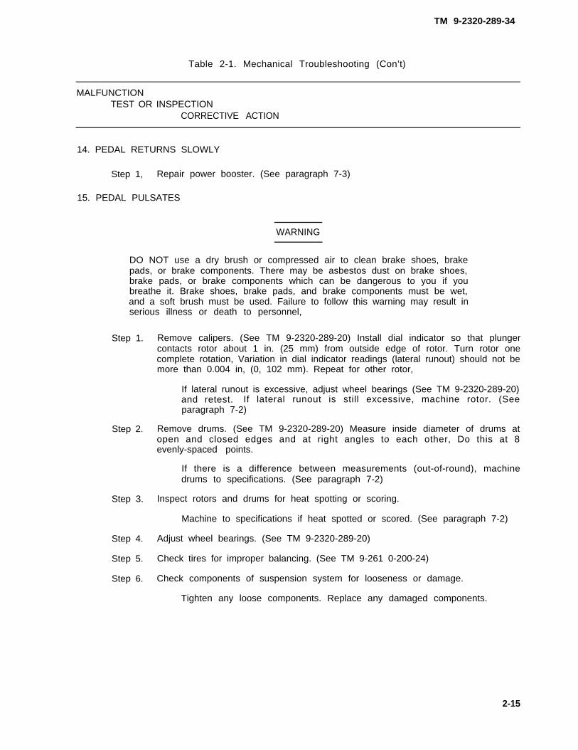
14. PEDAL RETURNS SLOWLY
Step 1, Repair power booster. (See paragraph 7-3)
15. PEDAL PULSATES
WARNING
DO NOT use a dry brush or compressed air to clean brake shoes, brakepads, or brake components. There may be asbestos dust on brake shoes,brake pads, or brake components which can be dangerous to you if youbreathe it. Brake shoes, brake pads, and brake components must be wet,and a soft brush must be used. Failure to follow this warning may result inserious illness or death to personnel,
Step 1. Remove calipers. (See TM 9-2320-289-20) Install dial indicator so that plungercontacts rotor about 1 in. (25 mm) from outside edge of rotor. Turn rotor onecomplete rotation, Variation in dial indicator readings (lateral runout) should not bemore than 0.004 in, (0, 102 mm). Repeat for other rotor,
If lateral runout is excessive, adjust wheel bearings (See TM 9-2320-289-20)and retest. If lateral runout is still excessive, machine rotor. (Seeparagraph 7-2)
Step 2. Remove drums. (See TM 9-2320-289-20) Measure inside diameter of drums atopen and closed edges and at right angles to each other, Do this at 8evenly-spaced points.
If there is a difference between measurements (out-of-round), machinedrums to specifications. (See paragraph 7-2)
Step 3. Inspect rotors and drums for heat spotting or scoring.
Machine to specifications if heat spotted or scored. (See paragraph 7-2)
Step 4. Adjust wheel bearings. (See TM 9-2320-289-20)
Step 5. Check tires for improper balancing. (See TM 9-261 0-200-24)
Step 6. Check components of suspension system for looseness or damage.
Tighten any loose components. Replace any damaged components.
2-15

TM 9-2320-289-34
Table 2-1. Mechanical Troubleshooting (Con’t)
MALFUNCTIONTEST OR INSPECTION
CORRECTIVE ACTION
ENGINE
16. WILL NOT CRANK OR CRANKS SLOWLY BUT WILL NOT START
Step 1. Remove torque converter cover and inspect flywheel for chipped or damagedteeth.
Replace flywheel if teeth are chipped or damaged. (See paragraph 3-15)
Step 2. Test starter, (See paragraph 4-5)
17, CRANKS NORMALLY BUT WILL NOT START
Step 1.
Step 2.
Step 3.
Step 4.
Step 5.
Check for voltage at pink lead on fuel injector pump fuel shutoff solenoid whileassistant cranks engine. There should be at least 9 volts.
If voltage is not correct, trace circuit. (See wiring diagram E-3 or E-5)
If voltage is correct, perform step 2.
Disconnect pink lead from fuel injector pump fuel shutoff solenoid. Turn key to“RUN” position, Touch pink lead to fuel injector pump terminal and listen forclicking sound.
If clicking sound is not heard, remove governor cover. (See paragraph 3-38)Connect 12 volt power source to shutoff solenoid terminal and ground.Observe solenoid plunger for freedom of movement. Clean or replacesolenoid if plunger sticks.
If clicking sound is heard, perform step 3.
Check fuel injector pump timing. (See paragraph 3-44)
Remove any glow plug. (See TM 9-2320-289-20) Have assistant depressaccelerator pedal halfway and crank engine for 5 seconds.
Test
Step 6. Test
If no fuel mist is observed in glow plug hole, check for restrictions in fuelreturn system. Clear any restrictions.
If fuel mist is observed in glow plug hole, remove remaining glow plugs andrepeat test, Test fuel injector nozzle for each glow plug hole that does nothave fuel vapors. (See paragraph 3-36)
fuel injector pump. (See paragraph 3-44)
compression of each cylinder. (See paragraph 3-2)
2 - 1 6

Table 2-1. Mechanical Troubleshooting (Con’t)
TM 9-2320-289-34
MALFUNCTIONTEST OR INSPECTION
CORRECTIVE ACTION
18. WHITE SMOKE (AIR TEMPERATURE WARM)
NOTE
Perform step 1 if white smokes only appears during starting.
Step 1. Check for inoperative glow plug module. (See TM 9-2320-289-20)
Step 2. Check fuel injector pump timing, (See paragraph 3-44)
WARNING
Use extreme caution to ensure that clothing or tools DO NOT get caught intruck’s operating drivebelts. Failure to follow this warning may result inserious injury to personnel or equipment damage.
Step 3. Start engine, Depress bottom of rocker lever on right side of fuel injector pump,
If engine sound doesn’t change, remove and inspect fuel injector pumpservo advance piston assembly. (See paragraph 3-40)
Step 4. Test compression of each cylinder. (See paragraph 3-2)
Step 5. Check timing chain free play. (See paragraph 3-1 1)
19. EXCESSIVE BLACK SMOKE
Step 1. Check fuel injector pump timing. (See paragraph 3-44)
Step 2. Test each fuel injector nozzle. (See paragraph 3-36)
Step 3. Test compression of each cylinder. (See paragraph 3-2)
20. IDLES ROUGH ON COLD-STARTS BUT CLEARS UP AFTER WARM-UP
Step 1. Check fuel injector pump timing. (See paragraph 3-44)
Step 2. Test fuel injector pump, (See paragraph 3-44)
2-17

TM 9-2320-289-34
Table 2-1. Mechanical Troubleshooting (Con’t)
MALFUNCTIONTEST OR INSPECTION
CORRECTIVE ACTION
WARNING
Use extreme caution to ensure that clothing or tools DO NOT get caught intruck’s operating drivebelts. Failure to follow this warning may result inserious injury to personnel or equipment damage.
Step 3. Start engine, Depress bottom of rocker lever on right side of fuel injector pump.
If engine sound doesn’t change, remove and inspect fuel injector pumpservo advance piston assembly. (See paragraph 3-40)
Step 4. Start engine. Loosen fuel injector line fitting at any fuel injector nozzle until fuelstarts to come from fitting.
If there is no engine rpm drop, test fuel injector nozzle. (See paragraph 3-36)
If there is engine rpm drop, tighten fitting to 20 Ib. -ft. (27 N.m) with crowfootattachment J-29698-A and repeat check for each fuel injector nozzle.
21. IDLES ROUGH WITHOUT ABNORMAL NOISE OR SMOKE, WILL NOT CLEAR UP
Step 1. Check fuel injector pump timing. (See paragraph 3-44)
Step 2. Test each fuel injector nozzle. (See paragraph 3-36)
Step 3. Remove governor cover. (See paragraph 3-38) Check for black particles.
If black particles are evident, replace governor weight retaining ring. (Seeparagraph 3-42)
Step 4. Test fuel injector pump, (See paragraph 3-44)
Step 5. Test compression of each cylinder. (See paragraph 3-2)
22. STARTS BUT WILL NOT CONTINUE TO RUN AT IDLE
Step 1. Check fuel injector pump timing. (See paragraph 3-44)
Step 2. Have assistant start engine. Check fast idle solenoid to see if solenoid holds fuelinjector pump lever in fast idle position.
If fast idle solenoid does not operate properly, perform ElectricalTroubleshooting malfunction #7.
Step 3. Test each fuel injector nozzle. (See paragraph 3-36)
Step 4. Test fuel injector pump, (See paragraph 3-44)
Step 5. Test compression of each cylinder. (See paragraph 3-2)
2-18

TM 9-2320-289-34
Table 2-1, Mechanical Troubleshooting (Con’t)
MALFUNCTIONTEST OR INSPECTION
CORRECTIVE ACTION
23. KNOCKS AT IDLE WHEN HOT
Step 1, Inspect torsional damper for looseness.
I f to rs iona l damper i s loose , remove crankshaft pulley. (SeeTM 9-2320-289-20) Insert tool through slot in torsional damper, against frontlip of engine oil pan, to keep crankshaft from turning. Tighten bolt to 200 Ib.-ft.(271 Nom). Install crankshaft pulley.
Step 2. Perform Mechanical Troubleshooting malfunction #34.
NOTE
If pistons are not defective, retarding fuel injector pump timing will quietdown combustion knock.
Step 3. Loosen fuel injector pump nuts. Rotate fuel injector pump to retard timing as far as itwill go. Start engine. If knocking is not reduced, loosen any fuel injector line fitting atfuel fuel injector. Knocking tone will change at fuel line feeding defective piston.Tighten fitting to 20 Ib.-ft, (27 N.m) with crowfoot attachment J-29698-A and repeatcheck until all defective pistons are located. Reset fuel injector pump timing. (Seeparagraph 3-44)
Remove and inspect any defective pistons, connecting rods, and connectingrod bearings. (See paragraph 3-1 3)
Step 4. Remove engine oil pan. (See TM 9-2320-289-20) Check clearance between connecting rod bearing caps. (See paragraph 3-1 3)
24, EXCESSIVE OIL LOSS
Step 1. Test compression of each cylinder. (See paragraph 3-2)
Step 2. Remove, clean, and inspect valves. (See paragraph 3-8)
Repair valves if necessary.
25. OIL PRESSURE LIGHT ON AT IDLE
Step 1. Remove, disassemble, and inspect engine oil pump and oil filter valve. (Seeparagraph 3-33)
Step 2. Check main bearing clearance. (See paragraph 3-1 4)
Step 3. Remove hydraulic valve lifter clamps and guide plates. (See paragraph 3-9)Measure hydraulic valve lifter clearance where it contacts its bore, parallel with rollerand 90 degrees to roller. Clearance should not be more than 0,005 in. (O. 130 mm).Repeat for each hydraulic valve lifter.
Replace hydraulic valve lifters that have excessive clearance.
Change 2 2-19

TM 9-2320-289-34
Table 2-1. Mechanical Troubleshooting (Con’t)
MALFUNCTIONTEST OR INSPECTION
CORRECTIVE ACTION
step 4. Drain cooling system. (See TM 9-2320-289-20) Remove engine mounts. (Seeparagraph 3-3) Remove starter. (See TM 9-2320-289-20) Inspect 2 oil galley plugsat front of engine block and 7 oil galley plugs at rear of engine block. Oil galleyplugs should be flush with engine block.
If oil galley plugs are damaged or recessed in engine block, cut slot in oilgalley plug with chisel, pry out, and discard. Apply sealant (Item 56,Appendix B) to new oil galley plug, and using oil galley plug installer, driveinto engine block until flush.
If oil galley plugs protrude from engine block, drive into engine block untilflush using oil galley plug installer.
26. OVERHEATS
Step 1.
Step 2.
Step 3.
Step 4.
Step 5.
Step 6.
Attempt to spin fan and fan clutch by hand.
If fan and fan clutch revolve more than five times without drag, replace fanclutch. (See TM 9-2320-289-20)
Visually check to see if lateral movement of fan, as measured at fan blade,exceeds approximately 0.25 in. (6.35 mm).
If lateral movement exceeds approximately 0.25 in. (6,35 mm), replace fanclutch. (See TM 9-2320-289-20)
Check for silicone fluid leakage around fan clutch bearing assembly. Small leakagewill not normally affect operation.
If silicone fluid leakage appears excessive, replace fan clutch. (SeeTM 9-2320-289-20)
Start engine, allow to reach operating temperature, then shut off, Carefully feelradiator from right side to left side. Radiator should be warm on right side and hoton left side, with an even temperature rise from right to left. Cold spots indicaterestrictions.
Repa i r o r rep lace rad ia to r i f t he re a re any res t r i c t i ons . (SeeTM 9-2320-289-20 and TM 750-254)
Start engine and check for leakage from water pump and water pump plate.
If leakage is evident, replace water pump. (See paragraph 3-48)
Inspect each cylinder head gasket for leakage.
If there is leakage, remove and inspect cylinder head. (See paragraph 3-7) Ifcylinder head does not require replacement, replace cylinder head gasketand install cylinder head.
2-20

TM 9-2320-289-34
Table 2-1, Mechanical Troubleshooting (Con’t)
MALFUNCTIONTEST OR INSPECTION
CORRECTIVE ACTION
27. NOTICEABLE LOSS OF POWER
Step 1. Check fuel injector pump timing. (See paragraph 3-44)
Step 2. With engine running, check for compression leaks at all fuel injector nozzles andglow plugs.
Tighten any leaking glow plugs to 10 Ib, -ft. (14 N.m). Tighten any leaking fuelinjector nozzles to 50 Ib, -ft. (68 Nom). Repeat check. If leaks are still found,replace glow plug (see TM 9-2320-289-20) or fuel injector nozzle gasket (seeparagraph 3-5).
Step 3. Test each fuel injector nozzle. (See paragraph 3-36)
Step 4. Test compression of each cylinder, (See paragraph 3-2)
28. HEAVY KNOCK WITH ENGINE TORQUE APPLIED
Step 1. Check to see if f lywheel is contacting torque converter cover. Checkflywheel-to-torque converter bolts for looseness.
Reposition torque converter cover if interfering with flywheel. Tighten bolts to50 Ib.-ft. (68 N.m) if loose.
Step 2. Inspect crankshaft pulley, fan pulley, and torsional damper for Iooseness.
Tighten crankshaft pulley or fan pulley if loose. If torsional damper is loose,remove crankshaft pulley. Insert tool through slot in torsional damper, againstfront lip of engine oil pan, to keep crankshaft from turning. Tighten bolt to200 Ib.-ft. (271 N.m), Install crankshaft pulley. Tighten crankshaft pulleybolts to 30 Ib, -ft. (41 Nom).
Step 3. Check main bearing clearance. (See paragraph 3-1 4)
Step 4. Check connecting rod bearing clearance. (See paragraph 3-1 3)
29. KNOCKS WHEN COLD, BUT CLEARS UP AFTER WARM-UP, INCREASES WITH ENGINETORQUE
Step 1. Check to see if flywheel is contacting torque converter cover.
Reposition torque converter cover if interfering with flywheel.
Step 2. Inspect crankshaft pulley, fan pulley, and torsional damper for looseness.
Tighten crankshaft pulley or fan pulley if loose. If torsional damper is loose,remove crankshaft pulley. Insert tool through slot in torsional damper, againstfront lip of engine oil pan, to keep crankshaft from turning. Tighten bolt to200 Ib. -ft. (271 N.m), Install crankshaft pulley. Tighten crankshaft pulleybolts to 30 Ib.-ft. (41 N.m).
Step 3. Check fuel injector pump timing. (See paragraph 3-44)
2-21
TM 9-2320-289-34
Table 2-1. Mechanical Troubleshooting (Con’t)
MALFUNCTIONTEST OR INSPECTION
CORRECTIVE ACTION
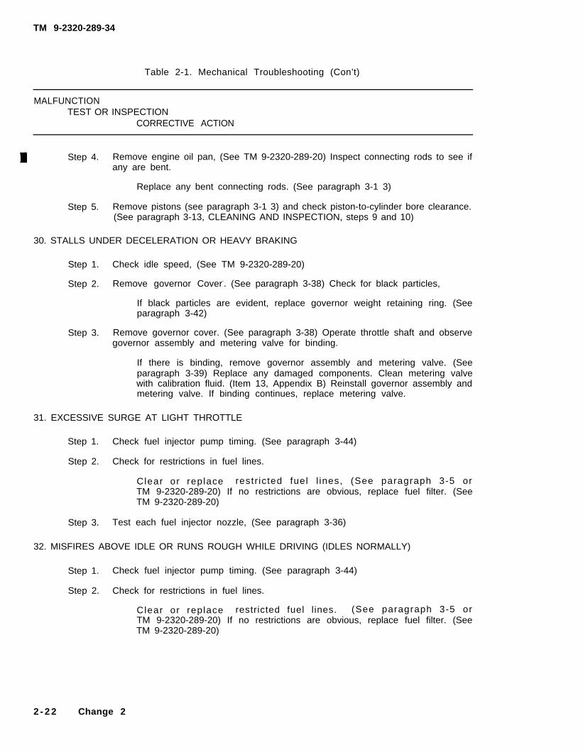
Step 4. Remove engine oil pan, (See TM 9-2320-289-20) Inspect connecting rods to see ifany are bent.
Replace any bent connecting rods. (See paragraph 3-1 3)
Step 5. Remove pistons (see paragraph 3-1 3) and check piston-to-cylinder bore clearance.(See paragraph 3-13, CLEANING AND INSPECTION, steps 9 and 10)
30. STALLS UNDER DECELERATION OR HEAVY BRAKING
Step 1. Check idle speed, (See TM 9-2320-289-20)
Step 2. Remove governor Cover-. (See paragraph 3-38) Check for black particles,
If black particles are evident, replace governor weight retaining ring. (Seeparagraph 3-42)
Step 3. Remove governor cover. (See paragraph 3-38) Operate throttle shaft and observegovernor assembly and metering valve for binding.
If there is binding, remove governor assembly and metering valve. (Seeparagraph 3-39) Replace any damaged components. Clean metering valvewith calibration fluid. (Item 13, Appendix B) Reinstall governor assembly andmetering valve. If binding continues, replace metering valve.
31. EXCESSIVE SURGE AT LIGHT THROTTLE
Step 1. Check fuel injector pump timing. (See paragraph 3-44)
Step 2. Check for restrictions in fuel lines.
Clear or replace restr icted fuel l ines, (See paragraph 3-5 orTM 9-2320-289-20) If no restrictions are obvious, replace fuel filter. (SeeTM 9-2320-289-20)
Step 3. Test each fuel injector nozzle, (See paragraph 3-36)
32. MISFIRES ABOVE IDLE OR RUNS ROUGH WHILE DRIVING (IDLES NORMALLY)
Step 1. Check fuel injector pump timing. (See paragraph 3-44)
Step 2. Check for restrictions in fuel lines.
Clear or replace restricted fuel lines. (See paragraph 3-5 orTM 9-2320-289-20) If no restrictions are obvious, replace fuel filter. (SeeTM 9-2320-289-20)
2 - 2 2 Change 2

TM 9-2320-289-34
Table 2-1, Mechanical Troubleshooting (Con’t)
MALFUNCTIONTEST OR INSPECTION
CORRECTIVE ACTION
33. BLUE SMOKE (ENGINE OIL BURNING IN CYLINDERS)
NOTE
Foamy or milky oil or rust on engine oil level indicator are evidence ofcontamination,
Step 1. Check engine oil level indicator for evidence of contamination.
Replace engine oi l and engine oi l f i l ter i f contaminated. (SeeTM 9-2320-289-20)
Step 2. Replace crankcase depression regulator valve assembly. (See TM 9-2320-289-20)
Step 3. Check compression of each cylinder. (See paragraph 3-2)
Step 4. Remove cylinder head. (See paragraph 3-7) Inspect valve oil seals and valveguides for damage.
Replace any damaged valve oil seals. (See paragraph 3-8) Repair valveguides if damaged. (See paragraph 3-8)
34. VALVE TRAIN NOISE
Step 1.
Step 2.
Step 3.
Step 4.
Start engine and allow to reach operating temperature. Connect STE/lCE tester toSTE/lCE DCA connector under dash. (See TM 9-4910-571-12&P) Check engine oilpressure at idle.
If oil pressure is less than 10 psiTroubleshooting malfunction #25.
If oil pressure is 10 psi (69 kPa) or more,
Check oil pressure at 2000 rpm.
(69 kPa), perform Mechanical
perform step 2.
If oil pressure is less than 40 psi (276 kPa), perform MechanicalTroubleshooting malfunction #25.
If oil pressure is 40 psi (276 kPa) or more, perform step 3.
Remove rocker arm covers. (See paragraph 3-6) Inspect rocker arm assembliesand mounting bolts for looseness and damage.
Tighten mounting bolts to 40 Ib, -ft, (54 N.m) if loose.
If rocker arms appear loose or damaged, see paragraph 3-6.
Remove cylinder heads. (See paragraph 3-7) Check to see if any valve springs arebroken.
Replace any broken valve springs. (See paragraph 3-8)
2 - 2 3
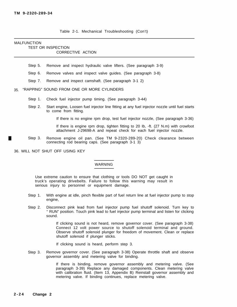
TM 9-2320-289-34
Table 2-1. Mechanical Troubleshooting (Con’t)
MALFUNCTIONTEST OR INSPECTION
CORRECTIVE ACTION
Step 5. Remove and inspect hydraulic valve lifters. (See paragraph 3-9)
Step 6. Remove valves and inspect valve guides. (See paragraph 3-8)
Step 7. Remove and inspect camshaft. (See paragraph 3-1 2)
35. “RAPPlNG” SOUND FROM ONE OR MORE CYLINDERS
Step 1. Check fuel injector pump timing. (See paragraph 3-44)
Step 2. Start engine, Loosen fuel injector line fitting at any fuel injector nozzle until fuel startsto come from fitting.
If there is no engine rpm drop, test fuel injector nozzle, (See paragraph 3-36)
If there is engine rpm drop, tighten fitting to 20 Ib, -ft. (27 N.m) with crowfootattachment J-29698-A and repeat check for each fuel injector nozzle.
Step 3. Remove engine oil pan. (See TM 9-2320-289-20) Check clearance betweenconnecting rod bearing caps. (See paragraph 3-1 3)
36. WILL NOT SHUT OFF USING KEY
WARNING
Use extreme caution to ensure that clothing or tools DO NOT get caught intruck’s operating drivebelts. Failure to follow this warning may result inserious injury to personnel or equipment damage.
Step 1. With engine at idle, pinch flexible part of fuel return line at fuel injector pump to stopengine,
Step 2. Disconnect pink lead from fuel injector pump fuel shutoff solenoid. Turn key to“ RUN” position. Touch pink lead to fuel injector pump terminal and listen for clickingsound.
If clicking sound is not heard, remove governor cover. (See paragraph 3-38)Connect 12 volt power source to shutoff solenoid terminal and ground.Observe shutoff solenoid plunger for freedom of movement. Clean or replaceshutoff solenoid if plunger sticks.
If clicking sound is heard, perform step 3.
Step 3. Remove governor cover. (See paragraph 3-38) Operate throttle shaft and observegovernor assembly and metering valve for binding.
If there is binding, remove governor assembly and metering valve. (Seeparagraph 3-39) Replace any damaged components. Clean metering valvewith calibration fluid. (Item 13, Appendix B) Reinstall governor assembly andmetering valve. If binding continues, replace metering valve.
2 - 2 4 Change 2

TM 9-2320-289-34
Table 2-1. Mechanical Troubleshooting (Con’t)
MALFUNCTIONTEST OR INSPECTION
CORRECTIVE ACTION
HEATER (ALL EXCEPT ENGINE COOLANT HEATER)
37. WILL NOT START
Step 1.
Step 2.
Step 3.
Step 4.
Step 5.
Step 6.
Replace igniter, (See paragraph 11-3)
Replace ignition control, (See paragraph 11-3)
Remove overheat switch. (See paragraph 11-3) Check for continuity throughswitch contacts.
If there is no continuity, replace overheat switch.
Remove frame detector switch. (See paragraph 11-3) Check condition of ceramicrod.
Replace ceramic rod if damaged.
Remove fuel control valve. (See paragraph 11-3) inspect all components forlooseness or damage. Check fuel line connectors for clogs.
Tighten any loose components. Replace any damaged components. Cleanfuel line connectors if clogged.
Remove burner. (See paragraph 11-3) Inspect vaporizer and wick for damage.
If only vaporizer or wick are damaged, replace. If both vaporizer and wick aredamaged, repair burner using rear vaporizer kit.
38. SMOKY HEATER EXHAUST AFTER 5 MINUTES CONTINUOUS OPERATION
Step 1. Remove fuel control valve. (See paragraph 11-3) Inspect all components forlooseness or damage.
Tighten any loose components. Replace any damaged components.
39. BLOWER MOTOR CONTINUES TO RUN AFTER HEATER IS TURNED OFF
Step 1. Remove flame detector switch. (See paragraph 11-3) Check condition of ceramicrod.
Replace ceramic rod if damaged.
2-25

TM 9-2320-289-34
Table 2-1. Mechanical Troubleshooting (Con’t)
MALFUNCTIONTEST OR INSPECTION
CORRECTIVE ACTION
ENGINE COO/ANT HEATER
40. WILL NOT START
Step 1. Replace igniter. (See paragraph 11-2)
Step 2. Remove limit switch. (See paragraph 11 -2) Check for continuity through switchcontacts.
If there is no continuity, replace limit switch.
Step 3. Replace flame switch. (See paragraph 11-2)
Step 4. Remove thermostat valve. (See paragraph 11-2) Inspect all components forlooseness or damage. Check fuel line connectors for clogs.
Tighten any loose components, Replace any damaged components. Cleanfuel line connectors if clogged.
41. WILL NOT SHUT OFF
Step 1. Disconnect electrical connector at electric fuel pump to shut off engine coolantheater, Remove thermostat valve. (See paragraph 11-2) Inspect all componentsfor looseness or damage, Check fuel line connectors for clogs.
Tighten any loose components. Replace any damaged components. Cleanfuel line connectors if clogged.
42. HEATER OPERATES; ENGINE REMAINS COLD
Step 1. Check engine coolant level.
Fill cooling system if low. (See LO 9-2320-289-12)
Step 2. Remove motor. (See paragraph 11-2) Check to see if coolant pump hoses,coolant pump passages, and blade slots are clogged. Inspect all components fordamage.
Disassemble and clean motor to remove clogs. Replace any damagedcomponents.
2-26

TM 9-2320-289-34
Table 2-1. Mechanical Troubleshooting (Con’t)
MALFUNCTIONTEST OR INSPECTiON
Correct ive ACTION
STEERING
43. EXCESSIVE PLAY IN STEERING
Step 1.
Step 2.
Step 3.
Step 4.
Step 5.
Step 6.
Inspect steering shaft couplings and flexible coupling for looseness and wear.
Tighten nuts and bolts if loose. Repair steering shaft (see paragraph 8-3) orreplace fIexible coupling if worn.
Inspect upper ball joints for wear (Ml 009 only),
Replace ball joints if worn. (See paragraph 6-12)
Adjust pitman shaft preload and bearing preload of power steering gear. (Seeparagraph 8-4)
Disconnect power steering pump-to-power steering gear line at power steeringgear. Check for worn power steering gear check valve.
Replace power steering gear check valve if worn. (See paragraph 8-4) Bleedpower steering system. (See TM 9-2320-289-20)
Adjust power steering gear bearing preload. (See paragraph 8-4)
Check for damaged or worn power steering gear.
Repair power steering gear if damaged or worn. (See paragraph 8-4)
44. HARD STEERING, LACK OF ASSIST, OR SLOW RETURN OF STEERING
Step 1.
Step 2.
Step 3.
Step 4.
Step 5.
Check alinement of power steering gear to steering column. Check to see ifflexible coupling is rubbing against power steering gear adjuster plug.
Adjust position of steering column if not in line with steering gear. Loosenpinch bolt of flexible coupling and assemble so that flexible coupling does notrub against power steering gear adjuster plug. Tighten pinch bolt to 30 lb.-ft.(41 N.m).
Adjust pitman shaft preload and bearing preload of power steering gear. (Seeparagraph 8-4)
Perform Mechanical Troubleshooting malfunction #45.
Disassemble power steering gear (see paragraph 8-4) and check for sticking orplugged spool valve.
Replace spool valve if sticking or plugged.
Remove, disassemble, and inspect steering column. (See paragraph 8-2)
Replace any damaged components.
2-27

TM 9-2320-289-34
Table 2-1. Mechanical Troubleshooting (Con’t)
MALFUNCTIONTEST OR INSPECTION
CORRECTIVE ACTION
45. POWER STEERING SYSTEM DOES NOT OPERATE PROPERLY
NOTE
Use suitable container to catch hydraulic fluid.
Step 1. Disconnect power steering pump-to-power steering gear line at power steeringgear. Install power steering system analyzer with valve on power steering gearside. Open valve. Start engine and run at idle. Check for leaks at fittings.
Tighten any leaking fittings.
Step 2. Bleed power steering system. (See TM 9-2320-289-20)
Step 3. Start engine and run at idle. Record flow rate and pressure.
If pressure is over 150 psi (1034 kPa), perform step 4.
If pressure is 150 psi (1034 kPa) or less, perform step 5.
Step 4. Shut off engine. Check for restrictions in power steering lines. Disconnect powersteering pump-to-power steering gear line at power steering gear. Inspect checkvalve for free operation. (See paragraph 8-4)
Clear any restrictions. Reposition or replace check valve if not operatingfreely.
Step 5. Partially close system analyzer valve to build pressure up to 700 psi (4827 kPa).Subtract current flow rate from flow rate in step 3.
If flow rate has dropped 1 gal. (3.785 1) per minute or more, repair powersteering pump. (See paragraph 8-5)
If flow rate has dropped less than 1 gal. (3.785 1) per minute, performstep 8.
CAUTION
DO NOT leave system analyzer valve fully closed for more than 5 seconds.Failure to follow this caution may result in damage to power steeringpump.
Step 6. Close and partially open system analyzer valve three times. Note highest pressureeach time valve is closed. All three readings must be 1350-1450 psi(9308-9998 kPa).
If all readings are within specifications, perform step 7.
If any reading is not within specifications, replace power steering pumpcontrol valve. (See paragraph 8-5)
2-28

TM 9-2320-289-34
Table 2-1. Mechanical Troubleshooting (con’t)
MALFUNCTIONTEST OR inspection
Correct ive ACTION
Step 7. Connect STE/lCE tester to STE/lCE DCA connector under dash. (SeeTM 9-4910-571-12&P) Raise engine speed to 1500 rpm. Subtract current flow ratefrom flow rate in step 3.
if flow rate has dropped 1 gal. (3.785 1) per minute or more, remove andclean power steering pump control valve. (See paragraph 8-5) Remove anyburrs with crocus cloth (Item 18, Appendix B). If hydraulic fluid is dirty, repairpower steering pump. (See paragraph 8-5)
If flow rate has dropped less than 1 gal. (3.785 1) per minute, performstep 8.
Step 8. Record current flow rate. Have assistant turn steering wheel all the way to left andall the way to right. Record flow rate at each stop.
If flow rate drops to less than 1 gal. (3.785 1) per minute at each stop,perform step 9.
If flow rate does not drop to less than 1 gal. (3.785 1) per minute at eachstop, repair power steering gear. (See paragraph 8-4)
Step 9. Run engine at idle speed. Have assistant turn steering wheel slightly to left and toright, Observe change in pressure readings. Pressure should drop immediately assteering wheel is turned, and raise immediately as steering wheel is straightened.
If pressure drops slowly; remove, disassemble, and clean power steeringgear valve assembly. (See paragraph 8-4) If hydraulic fluid is dirty, repairpower steering pump, (See paragraph 8-5)
46. NOISY STEERING
Step 1. Disassemble, clean, and inspect power steering pump. (See paragraph 8-5)
Step 2. Adjust pitman shaft preload of power steering gear. (See paragraph 8-4)
Step 3. Remove power steering gear valve assembly. (See paragraph 8-4) Inspect sealsfor damage.
Replace seals if damaged.
TRANSFER CASE
47. DIFFICULT TO SHIFT
Step 1. Disassemble transfer case. (See paragraph 5-21 or 5-22) Check for binding, worn,or damaged components inside transfer case.
Free any binding components if possible. Replace any worn or damagedcomponents.
2-29

TM 9-2320-289-34
Table 2-1. Mechanical Troubleshooting (Con’t)
MALFUNCTIONTEST OR inspection
Correct ive ACTION
48. NOISY
Step 1. Check for loose transfer case mounting bolts.
Tighten transfer case-to-adapter bolts if loose. Tighten 2 adapter-to-transmission support bolts to 40 lb. -ft. (54 N.m) if loose. Tighten 4transfer case-to-front propeller shaft bolts to 15 Ib.-ft. (20 N.m) if loose.
Step 2. Disassemble transfer case (see paragraph 5-21 or 5-22) and check for worn ordamaged bearings.
Replace any worn or damaged bearings.
49. EXCESSIVE FLUID LOSS
Step 1. Check for loose transfer case housing bolts.
Tighten front output shaft bolts to 35 Ib.-ft. (47 N.m) if loose. Tighten rearextension bolts to 30 Ib.-ft. (41 N.m) if loose.
Step 2. Check to see if transfer case vent is plugged or restricted.
Clear if plugged or replace if restricted.
Step 3. Disassemble transfer case (see paragraph 5-21seals and gaskets.
Replace any damaged seals and gaskets.
SO. CONTROL LEVER DISENGAGES FROM POSITION
or 5-22) and check for damaged
Step 1. Inspect selector rod at transfer case to see if it is bent or worn.
Replace selector rod if bent or worn. (See TM 9-2320-289-20)
Step 2. Disassemble transfer case (see paragraph 5-21 or 5-22) and check for worn ordamaged gears. Check for missing cap plug, shift ball, and poppet spring.
Replace worn or damaged gears. Install cap plug. shift ball, and poppetspring if missing.
2-30

TM 9-2320-289-34
Table 2-1, Mechanical Troubleshooting (Con’t)
MALFUNCTIONTEST OR INSPECTION
CORRECTIVE ACTION
TRANSMISSION
51. EXCESSIVE OIL LOSS
WARNING
Dry cleaning solvent P-D-680 is toxic and flammable. Always wearprotective goggles and gloves and us. only in a well-ventilated l rea. Avoidcontact with skin, l yes, and clothes l nd DO NOT breathe vapors. DO NOTus. near open flame or l xcesslvo heat. The solvent’s flash point Is100°F-1 38°F (38°C-S9°C). If you became dizzy while using cleaningsolvent, immediately get fresh air and medical help. if solvent contactseyes, immediately wash your eyes with water and get medical aid.
Step 1.
Step 2.
Step 3.
Thoroughly clean exterior of transmission and transfer case with dry cleaningsolvent (Item 23, Appendix B), and allow to air dry. Operate truck for about 10minutes, then shut off. Inspect transmission case and transfer case for leakage.
If hydraulic fluid is leaking from anywhere except front of transmission,inspect components for damage. Replace any damaged components,gaskets, or seals.
If hydraulic fluid is leaking from front of transmission, perform step 2.
Remove torque converter cover. Thoroughly clean and dry torque converter andtransmission oil pump. Chock rear wheels. Raise front of truck and support on jackstands. Have assistant start engine in “ P“ (Park). Observe torque converter andtransmission oil pump for area of leakage.
Replace any leaking components.
Check for loose transmission case-to-transfer case adapter bolts.
Tighten bolts to 30 Ib.-ft. (41 N.m) if loose.
NOTE
Thor. is no approved way to chock transmission oil filter for blockage orrestrictions.
Step 4. Remove transmission oil filter (see TM 9-2320-289-20) and check for water inhydraulic fluid. Inspect intake pipe and “O” ring for improper positioning anddamage.
Replace hydraulic fluid and transmission oil filter if any water is present.Replace intake pipe and “ O“ ring if damaged, Replace transmission oil filter ifblockage or restrictions are suspected.
2 - 3 1

TM 9-2320-289-34
Table 2-1. Mechanical Troubleshooting (Con’t)
MALFUNCTIONTEST OR INSPECTION
CORRECTIVE ACTION
Step 5. Remove transmission. (See paragraph 5-1 2) Inspect transmission case forporosity and damage.
Replace transmission case if porous or damaged,
52. NOISY IN PARK, NEUTRAL, AND ALL DRIVING RANGES
Step 1. Remove torque converter cover. (See paragraph 5-1 2) Check flywheel-to-torqueconverter bolts for looseness.
Tighten bolts to 50 Ib.-ft. (68 N.m) if loose.
NOTE
There Is no approved way to check transmission oil filter for blockage orrestrictions.
Step 2.
Step 3.
Step 4.
Remove transmission oil filter (see TM 9-2320-289-20) and check for water inhydraulic fluid. Inspect intake pipe and “O” ring for improper positioning anddamage.
Replace hydraulic fluid and transmission oil filter if any water is present,Replace intake pipe and “ O“ ring if damaged, Replace transmission oil filter ifblockage or restrictions are suspected,
Remove torque converter and inspect for damage, (See paragraph 5-1 2)
Remove, disassemble, clean, and inspect transmission oil pump. (Seeparagraph 5-1 5)
53. NOISY DURING ACCELERATION IN ALL DRIVING RANGES
Step 1, Check engine mounts, insulators, and attaching hardware for looseness anddamage.
Replace damaged components. (See paragraph 3-3) Tighten loose enginemount-to-insulator locknuts to 55 lb. -ft. (75 N.m), Tighten loose enginemount-to-engine bolts to 35 lb.-ft, (47 N.m).
Step 2. Check to see if transmission oil cooler lines are rubbing underbody.
Position transmission oil cooler lines clear of underbody if rubbing.
54. NOISY WITH TRANSMISSION GEARSHIFT SELECTOR IN “ 1,“ “2,” AND/OR REVERSE
Step 1. Remove, disassemble, clean, and inspect transmission intermediate clutch, frontinternal gear ring, and gear units. (See paragraph 5-1 9)
2 - 3 2

TM 9-2320-289-34
Table 2-1, Mechanical Troubleshooting (Con’t)
MALFUNCTIONTEST OR INSPECTION
CORRECTIVE ACTION
55. SQUEAL AT LOW SPEEDS, ESPECIALLY WHEN HOT
Step 1. Remove speedometer driven gear from transfer case. (See TM 9-2320-289-20) Inspect seal for damage. Inspect speedometer driven gear shaft to see if it istwisted.
Replace speedometer driven gear if shaft is twisted.
Step 2. Remove propeller shafts from transfer case. (See TM 9-2320-289-20) Check fordamage or lack of lubrication at output shaft seals.
Lubricate seals with hydraulic fluid (Item 40, Appendix B) or replace ifdamaged.
56. NO UPSHIFTS, DELAYED UPSHIFTS, OR FULL THROTTLE UPSHIFTS ONLY
Step 1. Disconnect downshift electrical connector from side of transmission. Operate truckand observe upshift performance.
If upshift is normal, replace transmission downshift switch on side ofaccelerator bracket.
If upshift performance is still poor, perform step 2.
Step 2. Connect downshift electrical connector to side of transmission. Test transmission oilpressure with brakes applied, “ D“ (Drive), engine at 1000 rpm. (See paragraph5-11)
If oil pressure is normal; remove, disassemble, clean, and inspect governorassembly. (See paragraph 5-5)
If oil pressure is high, perform step 3.
Step 3. Test transmission oil pressure with brakes applied, “N” (Neutral), engine at1000 rpm. (See paragraph 5-11)
If oil pressure is normal, perform step 4.
If oil pressure is high, perform step 5.
Step 4. Check for leaking or damaged detent solenoid.
Tighten detent solenoid if loose and replace if damaged. (See paragraph 5-7)
If detent solenoid is not loose or damaged, clean transmission control valveassembly. (See paragraph 5-7)
Step 5. Check for loose or damaged vacuum lines and hoses.
Connect vacuum hoses or vacuum lines if loose and replace if damaged. (SeeTM 9-2320-289-20)
Change 2 2-33

TM 9-2320-289-34
Table 2-1, Mechanical Troubleshooting (Con’t)
MALFUNCTIONTEST OR INSPECTION
CORRECTIVE ACTION
Step 6. Disconnect vacuum hose from vacuum pump. Install hose and vacuum gage onvacuum pump. Start engine. Calculate proper vacuum gage reading as shown inchart. Shut off engine.
If vacuum drops 1 in. Hg or more in less than 1,5 seconds, or if vacuum neverreaches proper gage reading, replace vacuum Dump. (SeeTM 9-2320~289-20) - -
Step 7.
57. ROUGH 1-2
Step 1.
Step 2.
Step 3.
Remove, clean, and inspect vacuum modulator assembly and modulator valve,(See paragraph 5-3)
SHIFT OR 2-3 SHIFf
Test transmission oil pressure with brakes applied, “ D“ (Drive), engine at1000 rpm. (See paragraph 5-11)
If oil pressure is normal, perform step 2.
If oil pressure is high, perform step 3.
Check for loose or damaged detent solenoid,
Tighten detent solenoid if loose and replace if damaged. (See paragraph 5-7)
If detent solenoid is not loose or damaged, clean transmission control valveassembly. (See paragraph 5-7)
Check for loose or damaged vacuum lines and hoses.
Connect vacuum hoses or vacuum lines if loose and replace if damaged, (SeeTM 9-2320-289-20)
2-34 Change 2

TM 9-2320-289-34
Table 2-1, Mechanical Troubleshooting (Con’t)
MALFUNCTIONTEST OR INSPECTION
CORRECTIVE ACTION
Step 4. Disconnect vacuum hose from vacuum pump. Install hose and vacuum gage onvacuum pump. Start engine. Calculate proper vacuum gage reading as shown inchart. Shut off engine.
If vacuum drops 1 in. Hg or more in less than 1.5 seconds, or if vacuumnever reaches proper gage reading, replace vacuum pump. (SeeTM 9-2320-289-20)
Step 5.
Step 6.
Step 7.
Step 8.
Remove, clean, and inspect vacuum modulator assembly and modulator valve.(See paragraph 5-3)
Remove and air check direct clutch for leak to outer area of direct clutch(See paragraph 5-1 7)
Repair direct clutch if it is leaking.
Remove, disassemble, clean, and inspect transmission oil pump.
piston.
(Seeparagraph 5-1 5)
Check for damage to intermediate clutch piston seals, second oil seal ring oncenter support, and center support assembly.
Replace any damaged components. (See paragraph 5-1 9)
58. LONG 1-2 SHIFT WITH END BUMP, 1-2 SLIPPAGE, OR EARLY 1-2 SHIFT
Step 1. Test transmission oil pressure with brakes applied, “ D“ (Drive), engine at1000 rpm. (See paragraph 5-11)
If oil pressure is normal, perform step 2.
If oil pressure is low, perform step 3.
2-35

TM 9-2320-289-34
Table 2-1. Mechanical Troubleshooting (Con’t)
MALFUNCTIONTEST OR INSPECTION
CORRECTIVE ACTION
Step 2. Check oil pressure test gage response to opening throttle. There should be rapid gage response to opening throttle.
If pressure response is good; remove, disassemble, clean, and inspecttransmission control valve assembly. (See paragraph 5-7)
If pressure response is poor; check for restricted vacuum hoses and lines.Clear any restrictions. Remove, clean, and inspect vacuum modulatorassembly and modulator valve. (See paragraph 5-3)
NOTE
There is no approved way to check transmission oil filter for blockage orrestrictions.
Step 3.
Step 4.
Step 5.
Step 6.
Step 7.
Step 8.
Remove transmission oil filter and check for water in hydraulic fluid. (SeeTM 9-2320-289-20) Inspect intake pipe and “ O“ ring for improper positioning anddamage.
Replace hydraulic fluid and transmission oil filter if any water is present.Replace intake pipe and “ O“ ring if damaged. Replace transmission oil filter ifblockage or restrictions are suspected.
Remove, disassemble, clean, and inspect transmission oil pump. (See paragraph5-15)
Check center support bolt for looseness. (See paragraph 5-1 9)
Tighten bolt to 25 Ib.-ft. (34 N.m) if loose.
Remove, disassemble, clean, and inspect transmission intermediate clutch. (Seeparagraph 5-1 9)
Disassemble, clean, and inspect forward clutch assembly. (See paragraph 5-1 6)
Remove and inspect center support seals and center support assembly, (Seeparagraph 5-1 9)
59. LONG 2-3 SHIFT WITH END BUMP, 2-3 SLIPPAGE, OR EARLY 2-3 SHIFT
Step 1. Perform Mechanical Troubleshooting malfunction #58.
Step 2. Remove, disassemble, clean, and inspect direct clutch assembly. (See paragraph5-1 7)
Step 3. Remove, disassemble, clean, and inspect front servo assembly, (See paragraph5-10)
2-36

TM 9-2320-289-34
Table 2-1. Mechanical Troubleshooting (Con’t)
MALFUNCTIONTEST OR inspection
Correct ive ACTION
60. FIRST AND SECOND SPEEDS ONLY; NO 2-3 SHIFT
Step 1.
Step 2.
Step 3.
Step 4.
Step 5.
Step 6.
Check tailpipe, muffler, exhaust manifolds, and exhaust pipe for restrictions.
Clear any restrictions.
Check for damaged or loose vacuum hoses. Remove, clean, and inspect vacuummodulator assembly and modulator valve. (See paragraph 5-3)
Remove, disassemble, clean, and inspect governor assembly.5-5)
Remove, disassemble, clean, and inspect transmission control(See paragraph 5-7)
Remove, disassemble, clean, and inspect direct clutch assembly,
(See paragraph
valve assembly,
(See paragraph5-17)
Remove, disassemble, clean, and inspect front servo assembly (see paragraph5-1 O) and rear servo assembly (see paragraph 5-9).
61. NO DRIVE OR SLIPS IN DRIVE
Step 1. Inspect transmission linkage for damage.
Replace any damaged components. (See paragraph 5-2)
Step 2. Test transmission oil pressure with brakes applied, “D” (Drive)) engine at1000 rpm, (See paragraph 5-11)
If oil pressure is low, perform step 3.
If oil pressure is normal, perform step 5.
NOTE
There is no approved way to check transmission oil filter for blockage orrestrictions.
Step 3. Remove transmission oil filter and check for water in hydraulic fluid. (SeeTM 9-2320-289-20) Inspect intake pipe and “O“ ring for improper positioning anddamage.
Replace hydraulic fluid and transmission oil filter if any water Is present.Replace intake pipe and “ O“ ring if damaged. Replace transmission oil filter ifblockage or restrictions are suspected.
Step 4. Remove, clean, and inspect vacuum modulator assembly and modulator valve.(See paragraph 5-3)
2-37

TM 9-2320-289-34
Table 2-1, Mechanical Troubleshooting (Con’t)
MALFUNCTIONTEST OR INSPECTION
Correct ive ACTION
Step 5. Remove, disassemble, clean, and inspect transmission oil pump. (See paragraph5-15)
Step 6. Remove, disassemble, clean, and inspect forward clutch assembly. (Seeparagraph 5-1 6)
Step 7. Remove, clean, and inspect roller clutch assembly. (See paragraph 5-1 9)
62. NO REVERSE OR SLIPS IN REVERSE
Step 1. Inspect transmission linkage for damage,
Replace any damaged components. (See paragraph 5-2)
Step 2. Test transmission oil pressure with brakes applied, “ R“ (Reverse), engine at1000 rpm. (See paragraph 5-11)
If oil pressure is normal, perform step 3.
If oil pressure is low, perform step 4.
NOTE
There is no approved way to check transmission oil filter for blockage orrestrictions.
Step 3.
Step 4.
Step 5.
Step 6.
Step 7.
Step 8.
Step 9.
Remove transmission oil filter and check for water in hydraulic fluid. (SeeTM 9-2320-289-20) Inspect intake pipe and “ O“ ring for improper positioning anddamage.
Replace hydraulic fluid and transmission oil filter if any water is present.Replace intake pipe and “O” ring if damaged. Replace transmission oil filter ifblockage or restrictions are suspected.
Remove, disassemble, clean, and inspect transmission oil pump, (See paragraph5-1 5)
Remove, disassemble, clean, and inspect transmission control valve assembly.(See paragraph 5-7)
Remove, disassemble, clean, and inspect rear servo assembly. (See paragraph5-9)
Remove, disassemble, clean, and inspect direct clutch assembly. (See paragraph5-17)
Remove and inspect rear band, (See paragraph 5-1 9)
Remove, clean, and inspect center support assembly and seals. (See paragraph5-1 9)
2-38

TM 9-2320-289-34
Table 2-1. Mechanical Troubleshooting (Con’t)
MALFUNCTIONTEST OR INSPECTION
CORRECTIVE ACTION
63. SLIPS IN SECOND OR SHIFTS 1-3 (MISSES SECOND)
Step 1. Remove, disassemble, clean, and inspect intermediate clutch assembly. (Seeparagraph 5-1 9)
Step 2. Inspect center support assembly, intermediate clutch, and intermediate clutchpiston seals. (See paragraph 5-1 9)
64. UPSHlTS PROPERLY; WILL NOT DOWNSHIFT
Step 1.
Step 2.
Step 3.
Disconnect downshift electrical connector from side of transmission. Connect testlight to terminal and ground. Turn key to “RUN” position. Have assistant depressaccelerator pedal fully.
If test light lights, check for loose or damaged detent solenoid. Tighten ifloose and replace if damaged. (See paragraph 5-7)
If test light does not light, perform step 2.
Trace circuit from transmission downshift switch on side of accelerator cablebracket. (See wiring diagram E-4 or E-6)
If circuit is good, replace transmission downshift switch.
Remove, disassemble, clean, and inspect transmission control valve assembly.(See paragraph 5-7)
65. NO ENGINE BRAKING WITH TRANSMISSION GEARSHIFT SELECTOR IN “2”
Step 1.
Step 2.
660 NO ENGINE
Step 1.
Step 2.
Step 3.
Remove, disassemble, clean, and inspect front servo assembly. (See paragraph5-10)
Remove, disassemble, clean, and inspect direct clutch assembly and front band.(See paragraph 5-1 7)
BRAKING WITH TRANSMISSION GEARSHIFT SELECTOR IN “1“
Remove transmission control valve assembly. (See paragraph 5-7) Check to see ifany check balls are missing or mispositioned, Inspect for damage at check ballseat pockets in transmission case.
Install check balls in correct position if missing or mispositioned.Transmission case must be replaced if check ball seat pockets are damaged.
Remove, disassemble, clean, and inspect rear servo assembly. (See paragraph5-9)
Remove and inspect rear band. (See paragraph 5-1 9)
2-39

TM 9-2320-289-34
Table 2-1. Mechanical Troubleshooting (Con’t)
MALFUNCTIONTEST OR INSPECTION
CORRECTIVE ACTION
67. TRUCK DRIVES WITH TRANSMISSION GEARSHIFT SELECTOR IN NEUTRAL
Step 1. Inspect transmission linkage for improper positioning and damage.
Adjust if out of position, Replace any damaged components, (See paragraph5-2)
Step 2. Remove parking pawl and bracket. (See paragraph 5-8) Inspect transmissioninternal linkage for damage.
Step 3. Remove, disassemble, clean, and inspect t ransmission oi l pump. (Seeparagraph 5-15)
Step 4. Remove, disassemble, clean, and inspect forward clutch assembly. (Seeparagraph 5-16)
68. WILL NOT HOLD IN PARK OR WiLL NOT RELEASE FROM PARK
Step 1. Inspect transmission linkage for improper positioning and damage. (Seeparagraph 5-2)
Step 2. Remove parking pawl and bracket. (See paragraph 5-8) Inspect transmissioninternal linkage for damage.
2-40

TM 9-2320-289-34
Table 2-2. Electrical Troubleshooting
MALFUNCTIONTEST OR INSPECTION
CORRECTIVE ACTION
AIR CONDITIONER
1. COOLING INSUFFICIENT
Step 1. Test air conditioning system, (See paragraph 10-20) Record low and high pressurereadings,
If low and high pressure readings are within specifications, system isoperational.
If high pressure reading is not within specifications, perform step 2.
Step 2. Check for 24 volts at light blue lead terminal at 24 volt air conditioner relay.
If there is voltage, system is operational.
If there is no voltage, perform step 3.
CAUTION
DO NOT operate air conditioner for extended periods with condensercover assembly removed. Failure to follow this caution may result indamage to air conditioning system due to high head pressure.
Step 3. Remove condenser cover assembly. (See TM 9-2320-289-20) Attempt to operateair conditioning system. Trace light blue lead from 24 volt air conditioner relay tored lead at low pressure switch. (See wiring diagram E-26)
If there is voltage, repair circuit.
If there is no voltage, perform step 4.
Step 4. Trace circuit to black lead on high pressure switch. (See wiring diagram E-26)
If there is voltage, replace low pressure switch. (See paragraph 10-27)
If there is no voltage, perform step 5.
Step 5. Remove air conditioner control panel. (See paragraph 10-22) Trace circuit to “A/CCOLD” switch. (See wiring diagram E-26)
If there is voltage, replace high pressure switch. (See paragraph 10-27)
If there is no voltage, perform step 6.
Step 6. Trace blue lead to “VENT-A/C” switch. (See wiring diagram E-26)
If there is voltage, replace “A/C COLD” switch. (See paragraph 10-22)
If there is no voltage, perform step 7.
2-41

TM 9-2320-289-34
Table 2-2. Electrical Troubleshooting (Con’t)
MALFUNCTIONTEST OR INSPECTION
CORRECTIVE ACTION
Step 7. Trace yellow lead to outside air door switch. (See wiring diagram E-26)
If there is voltage, replace “VENT-A/C” switch, (See paragraph 10-22)
If there is no voltage, perform step 8.
Step 8. Trace yellow lead to 12 volt air conditioner relay, (See wiring diagram E-26)
If there is voltage, replace outside air door switch. (See paragraph 10-22)
If there is no voltage, repair circuit.
2. ONE AIR CONDITIONER CONTROL INOPERATIVE (OTHER CONTROLS OPERATE)
Step 1. Pull out air conditioner control panel. (See paragraph 10-22, REMOVAL, steps 2and 3) Connect both battery negative cables. (See TM 9-2320-289-20) Check forvoltage to inoperative switch.
If there is voltage, disconnect both battery negative cables (seeTM 9-2320-289-20) and replace switch, (See paragraph 10-22)
If there is no voltage, trace circuit. (See wiring diagram E-26)
BATTERIES/CHARGING SYSTEM
3. GENERATOR LIGHT REMAINS ON OR TURNS ON DURING OPERATION (ALL EXCEPT Ml 010AND Ml 028 WITH 200 amp SYSTEM)
Step 1. Test appropriate alternator. (See paragraph 4-2)
4. VOLTMETER IN RED (OVERCHARGE) ZONE (ALL EXCEPT Ml 010 AND Ml 028 WITH 200 ampSYSTEM)
Step 1. Test appropriate alternator, (See paragraph 4-2)
5. VOLTMETER IN YELLOW (UNDERCHARGE) ZONE (Ml 010 AND Ml 028 WITH 200 ampSYSTEM)
Step 1. Remove current/voltage regulator cover. (See paragraph 4-4) With key in “OFF”position, check voltage at current/voltage regulator “1“ terminal.
If there is no voltage, repair circuit to front battery positive (+) terminal. (Seewiring diagram E-10)
If voltage is less than 12.0, perform step 2.
If voltage is 12.0-12.6, perform step 3.
2-42

TM 9-2320-289-34
Table 2-2. Electrical Troubleshooting (Con’t)
MALFUNCTIONTEST OR INSPECTION
CORRECTIVE ACTION
Step 2. Check f ron t ba t te ry fo r p roper charge and e lec t ro l y te leve l . (SeeTM 9-2320-289-20) Remove and clean front battery cable and clamp connections.
Service or replace front battery. Replace worn or damaged battery cablesand clamps. (See TM 9-2320-289-20)
Step 3. Check voltage at current/voltage regulator “2” terminal.
If there is no voltage, repair circuit to rear battery positive terminal. (Seewiring diagram E-10)
If voltage is less than 24.0, perform step 4.
If voltage is 24.0-25.2, perform step 5.
Step 4. Check rea r ba t te ry fo r p roper charge and e lec t ro l y te leve l . (SeeTM 9-2320-289-20) Remove and clean rear battery cable and clamp connections.
Service or replace rear battery. Replace worn or damaged battery cables andclamps. (See TM 9-2320-289-20)
Step 5. Turn key to “RUN” position. Check voltage at upper alternator positive (+)terminal.
If voltage is above 9.5, perform step 8.
If there is no voltage, perform step 6.
Step 6. Check voltage at current/voltage regulator “ A“ terminal.
If voltage is above 9.5, repair circuit to alternator positive (+) terminal. (Seewiring diagram E-10)
If there is no voltage, perform step 7.
Step 7. Check voltage at current/voltage regulator relay “IGN” terminal.
If there is no voltage, replace 20 amp engine control fuse (seeTM 9-2320-289-20) and trace circuit (see wiring diagram E-10).
If there is voltage, repair circuit to current/voltage regulator “A” terminal.(See wiring diagram E-10)
Step 8. Check voltage at upper alternator “IGN” terminal.
If voltage is above 9.5, perform step 11.
If there is no voltage, perform step 9.
Step 9. Check voltage at current/voltage regulator relay “FLD” terminal.
If voltage is above 10.5, repair circuit to upper alternator ”IGN” terminal.(See wiring diagram E-10)
If there is no voltage, perform step 10.
2-43

TM 9-2320-289-34
Table 2-2. Electrical Troubleshooting (Con’t)
MALFUNCTIONTEST OR INSPECTION
CORRECTIVE ACTION
Step 10. Check voltage at current/voltage regulator relay “A+” terminal.
if voltage is above 11.5, replace current/voltage regulator relay. (Seeparagraph 4-4)
if there is no voltage, trace circuit to front battery positive (+) terminal. (Seewiring diagram E-10)
CAUTION
DO NOT continue rotating adjustment screw after resistance is felt.Adjustment screw adjustment should never exceed 3/4 turn. Failure tofol low this caut ion may damage adjustment screw and requirereplacement of current/voltage regulator.
Step 11. Start engine, bring to full operating temperature, then shut off. Remove10 amp/28 v (voltmeter) fuse. (See TM 9-2320-289-20) Adjust current/voitageregulator adjustment screw completely clockwise. Connect tachometer inaccordance wit h manufacturer’s instructions. Start engine and operate at1200-1500 rpm. Check voltage at upper alternator positive (+) terminal for at least30 seconds.
if voltage is 15.5-16.5, replace current/voltage regulator. (See paragraph4-4) Repeat this step.
if voltage is 28.5-29,1, perform step 12.
if voltage is not 28.5-29.1, perform step 16.
CAUTION
DO NOT continue rotating adjustment screw after resistance is felt.Adjustment screw adjustment should never exceed 3/4 turn. Failure tofol low this caut ion may damage adjustment screw and requirereplacement of current/voltage regulator.
Step 12. Adjust current/voltage regulator adjustment screw completely counterclockwiseand check voltage at upper alternator positive (+) terminal for at least 30 seconds.
if voltage drops to 15,5-16.5, seal adjustment screw (see paragraph 4-4,iNSTALLATION, step 1 ) and perform step 15.
if voltage does not drop to 15.5-16.5, perform step 13.
2-44

TM 9-2320-289-34
Table 2-2. Electrical Troubleshooting (Con’t)
MALFUNCTIONTEST OR INSPECTION
CORRECTIVE ACTION
Step 13. Check voltage between rear battery positive (+) and negative (-) terminals.
If voltage is above 14,2, and voltage in step 12 does not drop, replacecurrent/voltage regulator, (See paragraph 4-4) Perform step 11,
If voltage is above 14,2, and voltage in step 12 drops to 16.5-26.5 or below15.5, replace current/voltage regulator relay. (See paragraph 4-4) Performstep 12.
If voltage is not above 14.2, perform step 14.
Step 14. Check rear battery for proper charge and electrolyte level . (SeeTM 9-2320-289-20) Remove and clean rear battery cable and clamp connections.
Service or replace rear battery. Replace worn or damaged battery cables andclamps. (See TM 9-2320-289-20) Perform step 12.
Step 15. Check voltage at current/voltage regulator relay “FLD” terminal for severalminutes, Voltage should be 6,0-11.0, drop to 0.0 for about 2 seconds eachminute, and return to 6.0-11.0.
If current/voltage regulator relay does not operate properly, replace. (Seeparagraph 4-4) Repeat this step.
If current/voltage regulator relay operates properly, perform step 190
Step 16 . Shu t o f f eng ine . Remove upper a l te rna to r vo l tage regu la to r (seeTM 9-2320-289-20) and ensure that adjustment screw is in “HI” position.
If adjustment screw is in “HI” position, perform step 18.
If adjustment screw is not in “HI” position, perform step 17.
Step 17. Install adjustment screw in “HI” position and install voltage regulator. (SeeTM 9-2320-289-20) Start engine and operate at 1200-1500 rpm. Check voltage atupper alternator positive (+) terminal.
If voltage is 28,5-29,1, perform step 12.
If voltage is not 28.5-29.1, perform step 18.
Step 18. Replace upper alternator voltage regulator. (See TM 9-2320-289-20) Start engineand operate at 1200-1500 rpm. Check voltage at upper alternator positive (+)terminal.
If voltage is 28.5-29.1, perform step 12.
If voltage is not 28.5-29.1, remove and test upper alternator. (Seeparagraph 4-3) Perform step 11,
Step 19. Shut off engine and install 10 amp/28 v (voltmeter) fuse. (See TM 9-2320-289-20)Start engine and check voltmeter.
If voltmeter is not in green zone, replace voltmeter. (See TM 9-2320-289-20)
2-45

TM 9-2320-289-34
Table 2-2. Electrical Troubleshooting (Con’t)
MALFUNCTION—
TEST OR INSPECTIONCORRECTIVE ACTION
6. VOLTMETER IN RED (OVERCHARGE) ZONE (Ml 010 AND Ml 028 WITH 200 amp SYSTEM)—
Step 1. Perform Electrical Troubleshooting malfunction #5, step 11.
STARTING SYSTEM
7. ENGINE STARTS BUT WILL NOT CONTINUE TO RUN AT IDLE
Step 1. Turn key to “RUN” position. Check for voltage at fast idle solenoid.
If there is voltage and fast idle solenoid plunger does not extend, replace fastidle solenoid. (See TM 9-2320-289-20)
If there is no voltage, perform step 2.
Step 2. Disconnect connector from cold advance switch at right rear of engine block. (Seewiring diagram E-3 or E-5) Jump light green and pink/black leads at connector,Check for voltage at fast idle solenoid.
If there is voltage and fast idle solenoid plunger does not extend, replace fastidle solenoid. (See TM 9-2320-289-20)
If there is voltage, fast idle solenoid plunger extends, and engine is cold,replace cold advance switch.
If there is voltage, fast idle solenoid plunger extends, and engine is hot,system operates properly.
If there is no voltage, trace circuit. (See wiring diagram E-3 or E-5)
WINDSHIELD WIPER/WASHER SYSTEM
8. WIPER MOTOR INOPERATIVE IN ONE SPEED
Step 1. Turn key to “ RUN” position, Turn wiper switch to inoperative speed position,Connect jumper wire from gray lead terminal on wiper motor to ground (if lowspeed inoperative) or from double white lead terminal on wiper motor to ground (ifhigh speed inoperative).
If wiper motor runs, trace circuit from wiper motor to switch. (See wiringdiagram E-20 or E-21)
If wiper motor does not run, remove end cap assembly from wiper motor.(See paragraph 10-8) Inspect brushes for damage. Replace any damagedbrushes in end cap assembly.
2-46

TM 9-2320-289-34
Table 2-2. Electrical Troubleshooting (Con’t)
MALFUNCTIONTEST OR INSPECTION
CORRECTIVE ACTION
9. WIPER SWITCH “OFF,” WIPER BLADES DO NOT RETURN TO PARK POSITION
Step 1. Turn key to “RUN” position, Turn wiper switch to “OFF” position. Connect jumperwire between park switch terminals (black/light blue lead terminal and white leadterminal beside it) on wiper motor,
If wiper motor runs, replace park switch, (See paragraph 10-8)
If wiper motor does not run, trace circuit through black/light blue lead fromwiper motor to switch, (See wiring diagram E-20 or E-21)
10. WIPER WILL NOT TURN OFF
Step 1. Turn key to “RUN” position. Turn wiper switch to “OFF” position. Disconnectconnector from park switch terminals (black/light blue lead terminal and white leadterminal beside it) on wiper motor.
If wiper motor stops, replace park switch. (See paragraph 10-8)
If wiper motor still runs, perform step 2.
Step 2. Disconnect 3-wire connector from windshield wiper motor. Connect 12 volt powersource to windshield wiper motor terminal #l.
If wiper motor does not run, trace all 3 circuits from 3-wire connector at wipermotor to switch for short to ground, (See wiring diagram E-20 or E-21)
If wiper motor still runs, remove end cap assembly from wiper motor. (Seeparagraph 10-8) Check for ground between brushes in end cap assembly.Replace brushes if grounded.
11. WIPER OPERATES IN ONE SPEED ONLY (SAME SPEED IN “LO” AND “HI”)
Step 1. Disconnect 3-wire connector from wiper motor, Operate wiper in “LO” and “H1.”
If wiper operates correctly in each wiper position, trace circuit from 3-wireconnector to switch. (See wiring diagram E-20 or E-21)
If wiper does not operate correctly in each wiper position, remove end capassembly from wiper motor. (See paragraph 10-8) check for short betweenbrushes in end cap assembly. Replace brushes if shorted.
2 - 4 7

TM 9-2320-289-34
Table 2-2. Electrical Troubleshooting (Con’t)
MALFUNCTIONTEST OR INSPECTION
CORRECTIVE ACTION
12. INTERMITTENT WIPER OPERATION
NOTE
Ensure that windshield is dry when performing test In step 1.
Step 1. Remove 25 amp windshield wiper fuse. (See TM 9-2320-289-20) Turn key to“RUN” position. Check current draw across fuse block terminals where fuse wasremoved with wiper in “HI” position. Record lowest current draw reading.
If current draw is less than 5 amps, replace windshield WIPER motor end capassembly. (See paragraph 10-8)
If current draw is more than 5 amps, perform step 2.
Step 2. Remove windshield wiper arms and blades. (See TM 9-2320-289-20) Repeat test instep 1.
If current draw is less than 5 amps, replace windshield wiper blades. (SeeTM 9-2320-289-20)
If current draw is more than 5 amps, Perform step 3.
Step 3. Disconnect windshield wiper linkage from windshield wiper crank arm (seeTM 9-2320-289-20) and repeat test in step 1.
If current draw is less than 5 amps, check windshield wiper linkage forbinding, Repair or replace windshield wiper linkage if binding. (SeeTM 9-2320-289-20)
If current draw is more than 5 amps, disassemble windshield wiper motor(see paragraph 10-8) and replace armature.
13. WINDSHIELD WIPER RUNS BUT BLADES WILL NOT MOVE
Step 1. Check windshield wiper linkage connection to wiper crank arm.
If linkage is connected, replace windshield wiper motor. (SeeTM 9-2320-289-20)
If linkage is not connected, connect linkage and check operation ofwindshield wiper.
14. WASHER INOPERATIVE (WIPER OPERATIVE)
Step 1. Check washer solvent container for proper level.
Step 2. Check washer nozzles and hoses for restrictions and damage.
Clear restrictions or replace if damaged. (See TM 9-2320-289-20)
2 - 4 8

TM 9-2320-289-34
Table 2-2. Electrical Troubleshooting (Con’t)
MALFUNCTIONTEST OR INSPECTION
CORRECTIVE ACTION
Step 3. Turn key to “RUN” position, Turn wiper to “ LO” position, then push washer buttonand listen for relay click.
If relay clicks, perform step 4.
If relay does not click, perform step 5.
NOTE
Ensure that 2-wire connector remains connected in step 4.
Step 4. Using test light, probe pink lead and white lead on 2-wire connector to washersolenoid.
If test light does not go on at both leads, trace white lead circuit from wipermotor to engine bulkhead connector. (See wiring diagram E-20 or E-21)
If test light goes on at one terminal only, replace park switch assembly. (Seeparagraph 10-8)
If test light goes on at both terminals and pink one is dim, ground pinkterminal at wiper motor. If washer pump operates, trace circuit from pinkterminal from wiper motor to switch. (See wiring diagram E-20 or E-21)
If washer pump does not operate, perform step 5.
Step 5. Disconnect all leads from windshield wiper motor. Remove washer pump cover.Reconnect 3-wire connector. Turn on wiper motor. Check operation of pawl onwasher pump.
If pawl moves, perform step 6.
If pawl does not move, check to see if washer pump dog spring is properlyconnected or pawl is not binding. Connect or replace if damaged. (Seeparagraph 10-8)
Step 6. Connect 12 volt power source to either washer pump solenoid terminal and groundother terminal for 2 seconds. Pawl should be pulled toward washer solenoid coil,pawl leg should drop down on gear ramp, and pawl should start rotating ratchetgear,
If system operates properly, perform step 7.
If pawl operates properly but ratchet gear does not rotate, check to ensurethat pawl engages gear teeth. Inspect pawl and gear for damage. Repositionor replace if damaged. (See paragraph 10-8)
If pawl leg does not clear rim on ratchet gear, check for burr on pawl leg.Remove burr with crocus cloth (Item 18, Appendix B) if present, Reposition orreplace washer pump solenoid if improperly positioned or damaged. (Seeparagraph 10-8)
2-49

TM 9-2320-289-34
Table 2-2, Electrical Troubleshooting (Con’t)
MALFUNCTIONTEST OR INSPECTION
Correct ive ACTION
Step 7. Check to see if piston actuator plate moves back and forth with cam follower pin.
If piston actuator plate moves, replace valve assembly (see paragraph 10-8)and recheck. If still inoperative, replace washer pump piston and housingassembly. (See paragraph 10-8)
If piston actuator plate does not move, replace washer pump piston andhousing assembly. (See paragraph 10-8)
15. WASHER WILL NOT SHUT OFF
Step 1.
Step 2.
Operate windshield wiper and disconnect pink lead and white lead connector fromwasher pump.
If washer stops, trace circuit from pink lead and white lead for ground fromconnector at wiper motor switch to wiper switch. (See wiring diagram E-20 orE-21)
If washer still operates, perform step 2.
Disconnect all leads from windshield wiper motor. Remove washer pump cover.Reconnect ail leads. Turn on windshield wiper switch. Check to see if ratchet geardog spring engages ratchet gear tooth. Check to see if retainer spring on ratchetgear is weak. Check to see if ratchet gear teeth or pawl are damaged.
Replace any damaged components. (See paragraph 10-8)
2-50

TM 9-2320-289-34
2-4. STE/lCE TROUBLESHOOTING.
Simplified Test Equipment for Internal Combustion Engines (STE/lCE) for use with the CUCVSeries trucks is in the process of being developed. When development is complete, STE/lCEtroubleshooting procedures will be added to this manual.
2-51/(2-52 blank)
TM 9-2320-289-34
CHAPTER 3ENGINE MAINTENANCE
Section L ENGINE ASSEMBLY MAINTENANCE
3-1. ENGINE ASSEMBLY MAINTENANCE INDEX.
ParagraphNumber
3-2.3-3.3-4.3-5.3-6.3-7.3-8.3-9.3-10.3-11.3-12.3-13.
3-14.3-15.3-16.3-17.3-18.3-19.
3-20.3-21.3-22.3-23.3-24.3-25.3-26.3-27.3-28.3-29.3-30.
P r o c e d u r e s
Compression Testing . . . . . . . . . . . . . . . . . . . . . . . . . . . . . . . . . . . . .Engine and Engine Mount Removal . . . . . . . . . . . . . . . . . . . . . . . . .Intake Manifold Removal . . . . . . . . . . . . . . . . . . . . . . . . . . . . . . . . . .Fuel Injector pipes and Nozzles Removal . . . . . . . . . . . . . . . . . . . . .Rocker Arm and Rocker Arm Cover Removal and Repair . . . . . . .Cylinder Head Removal . . . . . . . . . . . . . . . . . . . . . . . . . . . . . . . . . . .Valve Removal and Repair . . . . . . . . . . . . . . . . . . . . . . . . . .Hydraulic Valve Lifter Removal . . . . . . . . . . . . . . . . . . . . . . . . . . . . .Torsional Damper and Crankcase Cover Removal . . . . . . . . . . . . .Timing Chain and Sprockets Removal . . . . . . . . . . . . . . . . . . . . . . .Camshaft Removal . . . . . . . . . . . . . . . . . . . . . . . . . . . . . . . . . . . . .Piston, Connecting Rod, and Connecting Rod BearingRemoval and Repair . . . . . . . . . . . . . . . . . . . . . . . . . . . . . . . . . . . . . .Checking Main Bearing Clearance . . . . . . . . . . . . . . . . . . . . . . . . . .Crankshaft, Main Bearings, and Flywheel Removal . . . . . . . . . . . . .Camshaft Bearings Removal .. . . . . . . . . . . . . . . . . . . . . . . .Camshaft Bearings installation. . . . . . . . . . . . . . . . . . . . . . . . . . . . . .Crankshaft, Main Bearings, and Flywheel Installation . . . . . . . . . . .Piston, Connecting Rod, and Connecting Rod BearingInstallation . . . . . . . . . . . . . . . . . . . . . . . . . . . . . . . . . . . . . .Camshaft installation . . . . . . . . . . . . . . . . . . . . . . . . . . . . . . . . . . . . .Timing Chain and Sprockets Installation . . . . . . . . . . . . . . . . . . . . . .Torsional Damper and Crankcase Cover Installation . . . . . . . . . . . .Hydraulic Valve Lifter installation . . . . . . . . . . . . . . . . . . . . . . . . . . . .Valve installation. . . . . . . . . . . . . . . . . . . . . . . . . . . . . . . .Cylinder Head installation . . . . . . . . . . . . . . . . . . . . . . . . . . . . . . . . . .Rocker Arm and Rocker Arm Cover installation . . . . . . . . . . . . . . .Fuel injector Pipes and Nozzles Installation . . . . . . . . . . . . . . . . . . .intake Manifold installation . . . . . . . . . . . . . . . . . . . . . . . . . . . . . . . . .Engine and Engine Mount installation . . . . . . . . . . . . . . . . . . . . . . . .Engine Assembly Replacement . . . . . . . . . . . . . . . . . . . . . . . . . . . . .
PageNumber
3-23-33-8
3-113-143-203-243-283-293-333-35
3-373-443-473-533-563-58
3-613-663-683-693-743-763-783-813-853-883-923-98
3 - 1

TM 9-2320-289-34
3-2. COMPRESSION TESTING.
This task covers: a. Testing
INITIAL SETUP:
Equipment Condition Tools/Test Equipment
● Air cleaner removed. (See TM 9-2320-289-20) • Compression adapter, J-26999-30• Glow plugs removed. (See TM 9-2320-289-20) • Compression gage
Personnel Required
● Mos 63W (2)
a. TESTING
1.
2.
3.
4.
5.
CAUTION
DO NOT add oil to any cylinder for compression testing. Failure to followthis caution may result in extensive damage to engine.
Disconnect pink lead from fuel injector pump.
Install compression adapter and compression gage in glow plug hole of cylinder to be tested.
CAUTION
Covering should be removed from air Intake opening before crankingengine. Failure to follow this caution may result in damage to engine.
Record compression gage reading while assistant cranks engine. Allow six puffs per cylinder.
NOTE
Normal compression should be 380-400 psi (2620-2758 kPa).
Repeat steps 2 and 3 for each cylinder. Lowest cylinder reading should not be less than 80% ofhighest cylinder reading, and no cylinder reading should be less than 380 psi (2620 kPa).Remove and inspect valves and piston rings for any cylinder that fails test. (See paragraphs3-8 and 3-1 3)
Connect pink lead to fuel injector pump.
FOLLOW-ON TASKS:
● Install glow plugs. (See TM 9-2320-289-20)● Install air cleaner. (See TM 9-2320-289-20)
3 - 2

TM 9-2320-289-34
3-3. ENGINE AND ENGINE MOUNT REMOVAL.
This task covers: a. Removal
INITIAL SETUP:
Equipment Condition
Hood removed (if removing engine). (See TM 9-2320-289-20)Radiator and radiator hoses removed (if removing engine). (See TM 9-2320-289-20)Vacuum modulator pipe removed (if removing engine). (See paragraph 5-3)Engine coolant heater hoses removed (if removing engine equipped with winterization kits).(See TM 9-2320-289-20)Air conditioner compressor removed from brackets and tied aside (if removing Ml010engine). (See paragraph 10-24)Power steering pump dismounted from engine (if removing engine). (See TM 9-2320-289-20)Engine oil cooler lines disconnected from engine (if removing engine). (SeeTM 9-2320-289-20)Engine coolant heater front exhaust pipe and heat exchange pipe disconnected from engineoil pan (if removing engine equipped with winterization kits). (See TM 9-2320-289-20)Engine wiring harness disconnected from engine (if removing engine). (See paragraph 4-10)
Personnel Required
�● MOS 63W (2)
NOTE
If only removing engine mountor engine mount brackets,perform steps 5-8.
A suitable container should beu s e d t o c a t c h f u e l f r o mdisconnected fuel lines (1 and3).
Ensure that all hoses, Pipes,a n d l e a d s a r e t a g g e d f o rinstallation.
1.Disconnect fuel line (3) from fuelpump (2) and fuel return hose (1).
TA60616
3 - 3

TM 9-2320-289-34
3-3 . ENGINE AND ENGINE MOUNT REMOVAL (Con ’ t ) .
NOTE
Mark relationship of flywheel (9) totorque converter (8) forinstallation.
2. Remove 6 bol ts (4) and torqueconverter cover (6) f rom trans-mission a s s e m b l y ( 5 ) . R o t a t eflywheel and remove 6 bolts (7).
3. Remove 3 nuts (14), washers (13), and springs (12) and disconnect exhaust pipe fromexhaust manifold (11). Repeat for other exhaust manifold.
4. Disconnect transmission oil cooler pipes (1 O) at engine oil pan clip (15).TA50617
3 - 4

TM 9-2320-289-34
3-3. ENGINE AND ENGINE MOUNT REMOVAL (Con’t).
5. Remove locknut (20) and screw (16) from left side engine mount (21 ) and engine mountbracket (1 7), Repeat for right side. Discard locknuts. Disconnect positive starter cable fromclip on oil p-an.
●
●
●
CAUTION
When raising or supporting engine for any reason, DO NOT use jackunder engine oil pan, crankshaft puley, or any sheet metal. Usesuitable lifting device installed at lifting eyes. Failure to follow thiscaution may result in damage to engine oil pan, crankshaft pulley, orsheet metal.
If only removing engine mount (21) or engine mount brackets (17), andno other engine components have been removed, engine should onlybe raised until there is enough clearance to remove bolts (22). Raisingengine too far may result in damage to engine components.
If removing engine mounts (21) or engine mount brackets (17)) liftingdevice should be installed to right or left front of engine.
6. Install a suitable lifting device on engine lift brackets at left front and right rear of engine.Position wiring harness over transmission oil filler tube. Position vacuum modulator lines toright of lifting device.
7. Raise side of engine (19) where engine mount (21) is to be removed.
8. Remove 3 bolts (22), washers (23), engine mount bracket (17), and spacer (18) if damaged.Remove 3 locknuts, bolts, washers, and engine mount (21). Leave lift in place and repeat stepfor other side. Discard. locknuts and engine mount if damaged.
TA50618
3 - 5

TM 9-2320-289-34
3-3. ENGINE AND ENGINE MOUNT REMOVAL (Con’t).
9. Remove accelerator cable (24)retainer and disconnect acceleratorcable from support (25).
10. Loosen clamp (27) and disconnectheater inlet hose (26) from crossoverpipe (28).
3-6
TA50619

TM 9-2320-289-34
3-3. ENGINE AND ENGINE MOUNT REMOVAL (Con’t).
11. Lower engine to gain access to uppertransmission bol ts (29). Supporttransmission at transmission oil panusing suitable support.
12. Remove 6 transmission bolts (29).
CAUTION
Ensure that engine is completelydisconnected prior to lifting fromengine compartment. Failure tofollow this caution may result indamage to engine components.
NOTE
An assistant will guide engine outof engine compartment as it isbeing raised.
13. Slide engine straight forward todisengage locating pins fromtransmission. Remove engine fromengine compartment and install onengine stand. Remove lifting device.
FOLLOW-ON TASKS:
● Install engine or engine mounts. (See paragraph 3-29)
TA60620
3 - 7

TM 9-2320-289-34
3-4. INTAKE MANIFOLD REMOVAL.
This task covers: a, Removal b. Cleaning
INITIAL SETUP:
Equipment Condition ToolslTest Equipment
l Both battery negative cables disconnected l TWO manifold covers, J-29664-1(if being performed in truck).(See TM 9-2320-289-20) Manual References
. Crankcase depression regulator valve l TM 9-2320-289-20assembly and hoses removed (if beingperformed in truck). (See TM 9-2320-289-20)
a. REMOVAL
NOTE
Step 1 applies to all except M1010.
1. Remove bolt (2), nut (4), and brace (3) from left side alternator bracket (1) and long stud (5).
NOTE
Ensure that position of vacuum pump (7) is noted before rotating.
2. Loosen bolt (6) and rotate vacuum pump (7) to allow access to rear intake manifold bolt.
3. Disconnect 2 fuel filter hoses.
T A 6 0 6 2 1
3 - 8

TM 9-2320-289-34
3-4. INTAKE MANIFOLD REMOVAL (Con’t).
4. Remove long bolt (1 O), 7 short bolts (9), 4 long studs (5), and 4 short studs (11). Move fuelinjector pipe clips (12) clear of intake manifold (8). Remove intake manifold and 2 gaskets(13). Discard gaskets.
b . C L E A N I N G
CAUTION
Clean rags should be placed in cylinder head (14) openings beforecleaning. Ensure that old gasket material does not fall into cylinder headduring clearing. Failure to follow this caution may result in damage toengine.
1. Clean all gasket material from mating surfaces of intake manifold (8) and cylinder head (14).
2. Cover cylinder head (14) openings with manifold covers.TA50622
3 - 9

TM 9-2320-289-34
3-4. INTAKE MANIFOLD REMOVAL (Con’t).
FOLLOW-ON TASKS:
l Install intake manifold. (See paragraph 3-28)
3 - 1 0

TM 9-2320-289-34
3-5. FUEL INJECTOR PIPES AND NOZZLES REMOVAL.
This task covers: a, Removal
INITIAL SETUP:
Equipment Condition Tools/Test Equipment
● Intake manifold removed. (See paragraph 3-4) ● Crowfoot attachment, J-29698-A● Socket wrench adapter, J-29873
a, REMOVAL
NOTE
● If removing fuel injector pipes (8), perform steps 1-4.
● If removing fuel injector nozzles (6), perform steps 1-3, 5, and 6.
1. Remove 2 screws (1) and clips (2)from fuel injector pipe bracket (4) onone side. Remove clips and inserts(3) from fuel injector pipes (8).Discard inserts if damaged. Repeatstep for other side.
CAUTION
Ensure that al l openings andconnections are Immediatelyplugged after disconnection toprevent contaminat ion of fuelsystem.
NOTE
Ensure that fuel injector pipes (8),fuel injector nozzles (6), and Fuelinjector pump connectors aretagged for installation.
2. Disconnect 8 fuel injector pipes (8)from 8 fuel injector nozzles (6).Remove 4 nuts (7) and 2 fuel injectorpipe brackets (4) from cylinder headstuds (5) if damaged.
TA50623
3-11

TM 9-2320-289-34
3-5. FUEL INJECTOR PIPES AND NOZZLES REMOVAL (Con’t).
3. Disconnect 8 fuel injector pipes (8) from fuel injector pump (9) connectors and remove fuelinjector pipes.
NOTE
Ensure that locations of inserts are marked for installation.
4. Remove 4 clips (1 O) and inserts from fuel injector pipes (8). Remove 4 screws (13), clamps(1 2), and inserts (11) from fuel injector pipes. Discard inserts if damaged.
TA50624
3-12

TM 9-2320-289-34
3-5. FUEL INJECTOR PIPES AND NOZZLES REMOVAL (Con’t).
5. Remove nut (15) and clip (14).Loosen clamps and disconnect 8 fueldrainback hoses (16) f rom fuelinjector nozzles (6). Loosen clampsand remove 2 caps (17).
6. Using socket wrench adapter,remove 8 fuel injector nozzles (6)and fuel injector nozzle gaskets (18)from cylinder heads (1 9). Discardfuel injector nozzle gaskets.
FOLLOW-ON TASKS:
● Install fuel injector pipes or nozzles. (See paragraph 3-27)
TA50625
3 - 1 3

TM 9-2320-289-34
3-6. ROCKER ARM AND ROCKER ARM COVER REMOVAL AND REPAIR.
This task covers: a. Removal c. Cleaning and Inspectionb. Disassembly d. Assembly
INITIAL SETUP:
Equipment Condition MaterialslParts
● Fuel injector pipes removed.(See paragraph 3-5)
General Safety Instructions
● Dry cleaning solvent iswell-ventilated area.
flammable and must not be
• Cotter pins (as needed)• Rocker arm retainers (as needed)• Dry cleaning solvent
(Item 23, Appendix B)
used near open flame. Use only in a
a. REMOVAL
NOTE
• IF removing right rocker arm cover (3), perform steps 1-4.
• iF removing left rocker arm cover (8), perform steps 2-4.
1. Remove 2 nuts (2) and disconnect 2 vacuum line clamps (1) from studs (4) securing rightrocker arm cover (3).
2. Disconnect wiring harness from wiring harness clips along rocker arm cover (3 or 8). Ifremoving left rocker arm cover (8), remove wiring harness bracket.
3. Remove 2 nuts (6) and fuel injector pipe bracket (5).
TA60626
3 - 1 4

TM 9-2320-289-34
3-6. ROCKER ARM AND ROCKER ARM COVER REMOVAL AND REPAIR (Con’t).
CAUTION
DO NOT pry on rocker arm covers (3 and 8). Ensure that a soft-facedhammer Is used when removing rocker arm covers. Failure to follow thiscaution may result in damage to rocker arm covers or cylinder heads (11and 12).
4. For right rocker arm cover (3), remove 2 bolts (7), 6 studs (4), and rocker arm cover fromcylinder head (12). For left rocker arm cover (8), remove 5 bolts (9), 3 studs (10), and rockerarm cover from cylinder head (11).
TA50627
3-15
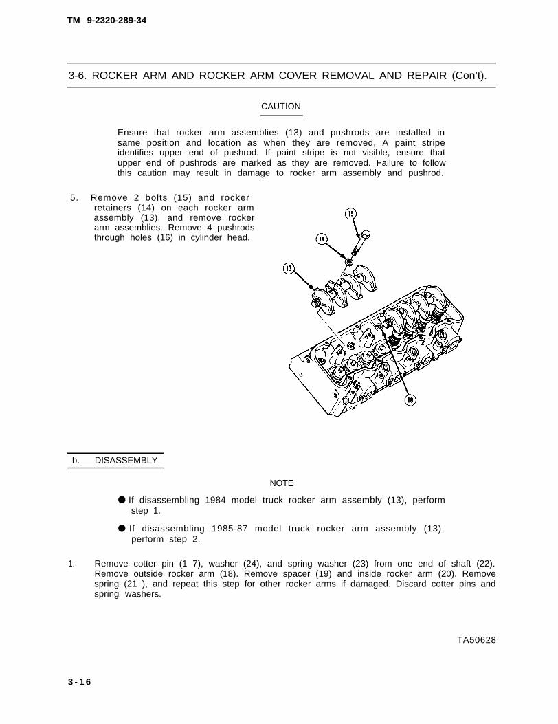
TM 9-2320-289-34
3-6. ROCKER ARM AND ROCKER ARM COVER REMOVAL AND REPAIR (Con’t).
CAUTION
Ensure that rocker arm assemblies (13) and pushrods are installed insame position and location as when they are removed, A paint stripeidentifies upper end of pushrod. If paint stripe is not visible, ensure thatupper end of pushrods are marked as they are removed. Failure to followthis caution may result in damage to rocker arm assembly and pushrod.
5. Remove 2 bolts (15) and rockerretainers (14) on each rocker armassembly (13), and remove rockerarm assemblies. Remove 4 pushrodsthrough holes (16) in cylinder head.
b. DISASSEMBLY
NOTE
● If disassembling 1984 model truck rocker arm assembly (13), performstep 1.
● If disassembling 1985-87 model truck rocker arm assembly (13),perform step 2.
1. Remove cotter pin (1 7), washer (24), and spring washer (23) from one end of shaft (22).Remove outside rocker arm (18). Remove spacer (19) and inside rocker arm (20). Removespring (21 ), and repeat this step for other rocker arms if damaged. Discard cotter pins andspring washers.
TA50628
3 - 1 6

TM 9-2320-289-34
3-6. ROCKER ARM AND ROCKER ARM COVER REMOVAL AND REPAIR (Con’t).
2. Remove retainer (27) from eachrocker arm (26) to be removed.Remove rocker arm from shaft (25).Discard retainers.
TA50629
3-17

TM 9-2320-289-34
3-6. ROCKER ARM AND ROCKER ARM COVER REMOVAL AND REPAIR (Con’t).
c. CLEANING AND INSPECTION
WARNING
Dry cleaning solvent P-D-680 is toxic and flammable. Always wearprotective goggles and gloves and use only in a well-ventilated area. Avoidcontact with skin, eyes, and clothes and DO NOT breathe vapors. DO NOTuse near open flame or excessive heat. The solvent’s flash point is100°F-138°F (38°C-59°C). If you become dizzy while using cleaningsolvent, immediately get fresh air and medical help. If solvent contactseyes, Immediately wash your eyes with water and get medical aid.
1. Using dry cleaning solvent, clean RTV sealant, oil, and grease from sealing surfaces of rockerarm cover and cylinder head.
2. Using dry cleaning solvent, clean all carbon and sludge from rocker arms and pushrods.
3. Inspect sealing flanges of rocker arm cover for distortion and damage. Inspect all rocker armcomponents for damage, Replace any damaged components.
d . ASSEMBLY
1.
NOTE
l If assembling 1964 model truck rocker arm assembly, perform step 1.
l If assembling 1985-67 model truck rocker arm assembly, performstep 2.
Install spring (21 ), inside rocker arm (20), and spacer (19) on shaft (22), Install outside rockerarm (18), new spring washer (23), washer (24), and new cotter pin (17) on shaft, Repeat thisstep until rocker arm assembly is assembled.
T A 5 0 6 3 0
3 - 1 8

TM 9-2320-289-34
3-6. ROCKER ARM AND ROCKER ARM COVER REMOVAL AND REPAIR (Con’t).
2. Center rocker arm (26) on hole inshaft (25) and install new retainer(27). Repeat this step until rockerarm assembly is assembled.
FOLLOW-ON TASKS:
l Install rocker arm and rocker arm cover. (See paragraph 3-26)
TA50631
3-19

TM 9-2320-289-34
3-7. CYLINDER HEAD REMOVAL.
This task covers: a. Removal b. Cleaning and Inspection
INITIAL SETUP:
Equipment Condition Materlals/Parts
Rocker arm cover, rocker arm assemblies,and pushrods on applicable cylinder headremoved, (See paragraph 3-6)Oil level indicator tube removed (if removingleft cylinder head). (See TM 9-2320-289-20)Air conditioner compressor bracketsremoved (if removing left cylinder headfrom Ml 01 O). (See paragraph 10-24)Left side alternator bracket removed(if removing left cylinder head).(See TM 9-2320-289-20)Right side alternator or Ml 010 alternatorbracket removed (if removing right cylinderhead), (See TM 9-2320-289-20)Exhaust manifold removed.(See TM 9-2320-289-20)Radiator, bypass, and heater hosesdisconnected (if being performed in truck).(See TM 9-2320-289-20)Thermostat and crossover pipe removed.(See TM 9-2320-289-20) “ ‘
● Fuel injector nozzle gaskets(as needed)
Tools/Test Equipment• Socket wrench adapter, J-29873
Personnel Required● MOS 63W (2)
Manual References● TM 9-2320-289-20
a . R E M O V A L
NOTE
● If engine is out of truck,perform step 2.
● Ensure that leads are tagged forinstallation.
1. Tag and disconnect glow plug leadsfrom glow plugs on cylinder head (5)to be removed. I f removing lef tcylinder head, disconnect glow plugwiring harness (2) from temperaturesensor (1), Remove nut, anddisconnect leads, ground strap, andIockwasher from engine stud. DiscardIockwasher.
TA50632
3-20

TM 9-2320-289-34
3-7. CYLINDER HEAD REMOVAL (Con’t) .
NOTE
● Rear bolt (6) in left cylinder head (5) may have to remain in cylinderhead during removal.
• An assistant will be required for step 2.
2. Remove 17 bolts (6), starting with outside bolts and working toward center. Remove cylinderhead (5) and cylinder head gasket (4) from engine block (3). Discard cylinder head gasket,
b. CLEANING AND INSPECTION
CAUTION
DO NOT use a motorized wire brush to clean cylinder head (5). Failure tofollow this caution may result In damage to cylinder head.
1. Inspect dowel pins (7) for damage. Remove if damaged.
2. Clean carbon deposits, sealing compound, and all gasket material from cylinder head (5) andengine block (3). Remove all sealant and dirt from threads in engine block.
3. Clean sealing compound from bolt (6) threads.
TA50633
3 - 2 1

TM 9-2320-289-34
3-7. CYLINDER HEAD REMOVAL (Con’t)..
NOTE
If replacing cylinder head, ensure that ail glow plugs, switches (seeTM 9-2320-289-20), fuel injector nozzles (see paragraph 3-5), and valves(see paragraph 3-8) are removed from damaged cylinder head andinstalled in new cylinder head.
4. Inspect cylinder head (5) for cracks between each intake port (8) and exhaust port (10).Inspect cylinder head where cylinder head gasket will be installed for nicks, heavy scratches,or other damage. Replace cylinder head if any of these conditions exists.
5. Using straightedge (12) and feelergage (11 ), measure cylinder head(5) for warpage. If warped more than0.006 in. (O. 15 mm) lengthwise or0.003 in. (0.08 mm) widthwise,replace cylinder head.
6. Check each prechamber (9) forproper installation. Prechamber mustnot be recessed in cylinder head (5).Prechamber should protrude fromsurface of cylinder head no morethan 0.002 in. (0.05 mm) at anypoint, Using straightedge (12) andfeeler gage (11), take thismeasurement at two or more pointson each prechamber. If prechamberprotrudes too far, tap into place withsocket and light mallet. If prechamberis recessed or damaged, performstep 7.
TA50634
3 - 2 2

TM 9-2320-289-34
3-7. CYLINDER HEAD REMOVAL (Con’t).
7. If prechamber (9) is cracked ordamaged, remove fuel injector nozzleand gasket on same cylinder asprechamber. Remove oldprechamber by placing punch intofuel injector nozzle hole and lightlytapping with hammer. Install newprechamber by al igning locatornotches (13) on prechamber andcylinder head (5). Using a 11/4 in.socket and light mallet, tap intoplace. Repeat measurements in step6, then install new gasket and fuelinjector nozzle.
FOLLOW-ON TASKS:
● Install cylinder head. (See paragraph 3-25)
TA50635
3-23

TM 9-2320-289-34
3-8. VALVE REMOVAL AND REPAIR.
This task covers: a. Removal c. Repairb, Cleaning and Inspection
INITIAL SETUP:
Equipment Condition Toola/Test Equipment
● Cylinder head removed. ● Buffing wheel(See paragraph 3-7) ● Dial indicator
● Torque wrenchGeneral Safety Instructions ● Valve guide cleaning tool
● Always wear goggles when using valve ● Valve guide reaming toolspring compressor. ● Valve spring compressor
● Valve spring tester
a. REMOVAL
WARNING
Always wear goggles while using valve spring compressor. Valve springs(6) are tightly compressed. Failure to follow This warning may result inserious injury to personnel.
1. Compress exhaust valve (3) spring or intake valve (2) spring and remove 2 keys (10).
TA50636
3-24

TM 9-2320-289-34
3-8. VALVE REMOVAL AND REPAIR (Con’t).
NOTE
Components of exhaust valve (3) assemblies and intake valve (2)assemblies are similar, except that exhaust valve uses rotater (11) andintake valve uses cap (11 ).
Ensure that location of each valve (12) and valve components aretagged as they are removed to ensure that they are installed in sameport during installation.
2. Remove rotater (11) or cap (11). Remove shield (8) and valve spring (6) with damper (7).Remove oil seal (9) and valve spring shim (5). Remove valve (12). Discard oil seal.
b. CLEANING AND INSPECTION
1. Clean valve (12) using buffing wheel.
2. Inspect valves (12) for burned heads, cracked faces, and damaged stems. Repair if burned orcracked. (See REPAIR, step 1) Replace valves if damaged. if repair will not bring cracked valvewithin specifications, replace valve.
TA50637
3-25

TM 9-2320-289-34
3-8. VALVE REMOVAL AND REPAIR (Con’t).
3. Thoroughly clean valve guides (4).Insert valve (12) in valve guide untilvalve head seats. Install dial indicator(13) on rocker arm cover gasket rail(14) so that it contacts valve stemjust above valve guide.
4. Move valve (12) until valve head is0,06 in. (1,6 mm) off valve seat.Using light pressure, move valvestem from side to side. If clearanceexceeds 0,0027 in. (0.06858 mm),repair valve and valve guide. (SeeREPAIR)
5. Set valve spring tester to 1.81 in.(46 mm). Put pressure on valvespring (6) with torque wrench untilheight is 1,81 in. (46 mm), Ifpressure is not 70-80 Ib,-ft.(95-1 08 Nom), replace valve spring.
6. Set valve spring tester to 1.39 in.(35.3 mm), Put pressure on valvespring (6) with torque wrench untilheight is 1.39 in. (35.3 mm). Ifpressure is not 220-230 Ib.-ft.(298-31 2 N.m), replace valve spring.
TA50636
3 - 2 6

TM 9-2320-289-34
3-8. VALVE REMOVAL AND REPAIR (Con’t).
NOTE
Valves (12) and seats should bereconditioned if seat widthexceeds 0.080 in. (2.03 mm),
1. Grind valve face (15) to obtain a 45degree angle completely around.Measure all valve heads (1 6). If valvehead is less than(0.80 mm) thick at any point, replacevalve (12).
CAUTION
Valve seats are inductionhardened. DO NOT grind valveseats in excess of dimensionsgiven in step 2. Failure to followthis caution may result in damageto valve seat and requirereplacement of cylinder head (1).
2. Grind valve seats to obtain a 46 degree angle. Intake valve (2) seats must be 0.035-0.060 in.(0.889-1 .52 mm) wide. Exhaust valve (3) seats must be 0.060-0.080 in. (1 .52-2 .03 mm)wide. If any valve seat is too wide, replace cylinder head (1).
3. Obtain valve (12) with next oversize stem. Using appropriate reaming tool for oversize valvestem, ream valve guide (4).
FOLLOW-ON TASKS:
● Install valve. (See paragraph 3-24)TA50639
3 - 2 7

TM 9-2320-289-34
3-9. HYDRAULIC VALVE LIFTER REMOVAL.
This task covers: a. Removal b. Inspection
INITIAL SETUP:
Equipment Condition Tools/Test Equipment
● Cylinder head removed. (See paragraph 3-7) • Magnet
I a. REMOVAL
1 Loosen bolt (5) and remove clamp(4). Remove guide plate (3).
NOTE
• If more than 1 hydraulic valvelifter (2) is removed, ensurethat location of each hydraulicvalve lifter is tagged, es it isremoved, to ensure that it isinstalled in same locationduring installation.
• For 1984 model truck engines,It may be necessary to usemechanical fingers to removehydraulic valve lifter (2),
Using magnet, remove hydraulicvalve lifter (2) from engine block (1),
b. INSPECTION
1.. Inspect hydraulic valve lifter (2) body for scuffing or scoring. Replace if scuffed or scored.
2. Inspect hydraulic valve lifter (2) roller for looseness and missing or broken needle bearings.Replace hydraulic valve lifter if these conditions exist.
3. Inspect hydraulic valve lifter (2) roller surface for pits and roughness. If these conditions exist,replace hydraulic valve lifter and inspect mating camshaft lobe for pits and roughness, Ifcamshaft lobe is pitted or rough, replace camshaft. (See paragraph 3-12)
FOLLOW-ON TASKS:
l Install hydraulic valve lifter. (See paragraph 3-23)
TA50640
3 - 2 8

TM 9-2320-289-34
3-10. TORSIONAL DAMPER AND CRANKCASE COVER REMOVAL.
This task covers: a. Removal b. Cleaning and Inspection
INITIAL SETUP:
Equipment Condition Tools/Test Equipment
● Crankshaft pulley removed. ● Torsional damper puller(See TM 9-2320-289-20)
● Engine oil drained (if removing crankcase General Safety Instructionscover). (See TM 9-2320-289-20) ● Avoid skin contact with anaerobic
● water pump removed (if removing crankcase sealing compound.cover). (See paragraph 3-48)
● Right side alternator bracket removed(if removing crankcase cover).(See TM 9-2320-289-20)
a. REMOVAL
1.
2.
2.1.
NOTE
If removing torsional damper (7), perform step 2.
If removing crankcase cover seal (9), perform steps 2 and 3.
Aline timing marks (5) on fuel injector pump driven gear ( 1 ) and fuel injector pump drive gear(4). Scribe a mark alining fuel injector pump flange (3) and crankcase cover (2). Remove 3 bolts(6) and fuel injector pump driven gear.
Remove bolt (11 ) and washer (1 O) from torsional damper (7), Install bolt in torsional damper. Using torsional damper puller, remove torsional damper from crankshaft (8).
Remove bolt (11 ) from crankshaft (8).
TA50641
C h a n g e 2 3-29

TM 9-2320-289-34
3-10. TORSIONAL DAMPER AND CRANKCASE COVER REMOVAL (Con’t).
CAUTION
Be careful not to scratch crankshaft (8) or crankcase cover (2) whenremoving crankcase cover seal (9). Failure to follow this caution mayresult in oil leakage.
3. Pry out and discard crankcase coverseal (9).
4. Remove 3 nuts (14) from fuel injector pump (13) at rear of crankcase cover (2).
TA50642
3 - 3 0

TM 9-2320-289-34
3-10 TORSIONAL DAMPER AND CRANKCASE COVER REMOVAL (Con’t).
5. Remove bolt (15) and disconnect clip(17) with fuel return line (16) fromcrankcase cover (2),
6. Remove nut (19), 2 bolts (18), and baffle (20).
7. Remove 4 bolts securing crankcase cover (2) to engine oil pan. Removebolts (23) and crankcase cover from engine block (21 ). Remove andpump gasket (12).
8.
bolt (22). Remove 4discard fuel injector
Remove 2 screws (25) and probe holder (24) from crankcase cover (2) if damaged or ifreplacing crankcase cover.
TA50643
3-31

TM 9-2320-289-34
3-10. TORSIONAL DAMPER AND CRANKCASE COVER REMOVAL (Con’t).
b. CLEANING AND INSPECTION
WARNING
Avoid skin contact with anaerobic sealing compound. Immediately washoff skin if contact is made. Failure to follow thisinjury to personnel.
1. Clean RTV sealant and anaerobic sealing compound fromall surfaces.
warning may result in
all sealing surfaces, Clean oil from
2. Inspect crankcase cover (2) for cracks, damage to sealing surface, and damage to crankcasecover seal opening. Replace crankcase cover if cracked or damaged.
3. Inspect fuel injector pump driven gear (1) for cracks and damaged teeth. Replace if crackedor teeth are damaged.
FOLLOW-ON TASKS:
● Install torsional damper and crankcase cover. (See paragraph 3-22)
TA50644
3-32

TM 9-2320-289-34
3-11. TIMING CHAIN AND SPROCKETS REMOVAL.
This task covers: a. Checking Timing Chain b. RemovalFree Play c. Inspection
INITIAL SETUP:
Equipment Condition Tools/Test Equipment
● Crankcase cover removed. • Dial indicator(See paragraph 3-10)
a. CHECKING TIMING CHAIN FREE PLAY
1.
2.
3.
4.
Mount dial indicator to front of engine block (5). Position dial indicator plunger so that it contactstiming chain (4) midway between camshaft sprocket (8) and crankshaft sprocket (9).
NOTE
When moving timing chain (4) to check free play, ensure that it is movedparallel to front face of engine block (5).
Applying finger pressure on inside of timing chain, move timing chain (4) outward as far as it willgo. With timing chain in maximum outward position, set dial indicator to “O.”
Applying finger pressure on outside of timing chain, move timing chain (4) inward as far as it willgo. With timing chain in maximum inward position, note dial indicator reading.
Maximum free play with used timing chain (4) must not exceed 0.80 in. (20.3 mm). Maximumfree play with new timing chain must not exceed 0.50 in. (12. 7 mm). If free play exceeds thislimit, replace timing chain and sprocket.
TA50645
Change 2 3-33

TM 9-2320-289-34
3-11. TIMING CHAIN AND SPROCKETS REMOVAL (Con’t).
b. REMOVAL
1. Remove bolt (1), thrust washer (2), and fuel injector pump drive gear (3).
2. Aline timing marks on camshaft sprocket (8) and crankshaft sprocket (9). Remove camshaftsprocket from camshaft (6), and crankshaft sprocket from crankshaft (7) with timing chain (4)attached.
3. Disassemble camshaft sprocket (8), crankshaft sprocket (9), and timing chain (4).
c. INSPECTION
1. Inspect timing chain (4) for cracks and damage. Replace if
2. Inspect fuel injector pump drive gear (3), camshaft Sprockclet
cracked or damaged.
(8),. and crankshaft sprocket (9)for cracks, damage,” and” rounded gear teeth. Replace if cracked, damaged, or gear teeth arerounded,
FOLLOW-ON TASKS:
● Install timing chain and sprockets. (See paragraph 3-21)
TA50646
3-34

TM 9-2320-289-34
3-12. CAMSHAFT REMOVAL.
This task covers: a. Removal b. Inspection
INITIAL SETUP:
Equipment Condition Tools/Test Equipment
● Engine removed. (See paragraph 3-3) ● Dial indicator● Hydraulic valve lifters removed. ● Two “V“ blocks
(See paragraph 3-9) . Micrometer● Timing chain and sprockets removed.
(See paragraph 3-1 1)● Fuel pump removed. (See TM 9-2320-289-20)● Vacuum pump removed,
(See TM 9-2320-289-20)
a. REMOVAL
1. Mark position of camshaft sprocket key (9) on engine block (4) for installation.
2. Install dial indicator on front of engine block (4) with plunger contacting end of camshaft (3).Attempt to move camshaft toward plunger. End play should not exceed 0.0140 in.(0.356 mm). If end play exceeds specifications, perform step 3 and INSPECTION.
CAUTION
Care should be taken when pulling camshaft (3) from engine block (4).Failure to follow this caution may result in damage to camshaft bearings.
3. Remove 2 bolts (1), plate (2), ring (8), and camshaft sprocket key (9). Remove camshaft (3).
TA50647
3-35

TM 9-2320-289-34
3-12. CAMSHAFT REMOVAL (Con’t).
b. INSPECTION
1. Measure diameter of camshaft journals. Rear camshaft journal (5) must be at least 2,0053 in.(50.935 mm) diameter. All other camshaft journals (7) must be at least 2.1628 in.(54.935 mm) diameter. If any camshaft journal is not within specifications, replace camshaftand appropriate camshaft bearing. (See paragraph 3-1 6)
2. Support camshaft (3) with front camshaft journal (7) and rear camshaft journal (5) in “V” blocks,
3. Secure dial indicator with plunger contacting low side of camshaft lobe (6). Set dial indicator to“o . “
4. Turn camshaft (3) until high side of camshaft lobe (6) contacts dial indicator plunger, Readingmust be at least 0.2769 in. (7,0330 mm).
5. Repeat steps 3 and 4 for each camshaft lobe (6), If any reading is not within specifications,replace camshaft.
6. Inspect plate (2), ring (8), and camshaft sprocket key (9) for wear or damage. Replace if wornor damaged,
FOLLOW-ON TASKS:
● Install camshaft, (See paragraph 3-20)
TA50648
3-36 Change 2

a. REMOVAL
TM 9-2320-289-34
3-13. PISTON, CONNECTING ROD, AND CONNECTING ROD BEARING REMOVALAND REPAIR.
This task covers: a. Removal c. Cleaning and Inspectionb. Disassembly d. Assembly
INITIAL SETUP:
Equipment Condition Mater/a/s/Parts
● Engine removed. (See paragraph 3-3) ● Dry cleaning solvent• Engine oil pump removed. (Item 23, Appendix B)
(See paragraph 3-33) ● 3/8 in. I.D. hose (Item 39, Appendix B)• Cylinder head removed (if removing piston ● Lubricating oil (Item 49, Appendix B)
and connecting rod). (See paragraph 3-7)
Tools/Test Equipment General Safety Instructions
● Micrometer ● Dry cleaning solvent is flammable and● Ridge reamer must not be used near open flame.● Snapring pliers Use only in a well-ventilated area.
● Always wear goggles when removingpiston pin retainers.
1,
2.
3.
4.
● Ensure
NOTE
that cylinder bore and components of connecting rod andpiston assembLy (5) are marked for installation.
● If removing connecting rod
Turn crankshaft (1) until piston to beremoved is at bottom of its stroke.
Place a cloth over piston. Removeany deposits from upper end ofcylinder bore. Use ridge reamer toremove wear ridge if present.
Remove 2 nuts (3) and connectingrod cap (4) from crankshaft (1)journal. Remove lower connecting rodbearing. DO NOT discard nuts at thistime.
Install short piece of 3/8 in. I.D. hose(2) over threads of connecting rodbolts. Remove piston and connectingrod assembly (5) through top ofcylinder bore. Remove upperconnecting rod bearing. Removehoses and retain for installation.
bearing, perform step 3.
TA50649
3-37

TM 9-2320-289-34
3-13. PISTON, CONNECTING ROD, AND CONNECTING ROD BEARING REMOVALAND REPAIR (Con’t).
b. DISASSEMBLY
WARNING
Always wear goggles when removing piston pin retainers (6). Failure tofollow this warning may result in serious injury to personnel.
1. Remove 2 piston pin retainers (6).Remove piston pin (7) and separatepiston (8) from connecting rod (14),Remove 2 bolts (13) only if damaged.
2. Expand upper compression ring (12)and slide from groove in piston (8).Repeat for lower compression ring(11 ), oil control ring (1 O), and oil ring
I
expander (9).
c . CLEANING AND INSPECTION
1.
2.
3.
4.
5.
Wipe oil from crankshaft journals, andupper and lower connecting rodbearing shells.
Inspect connecting rod bearings forscoring or damage. Replace if scoredor damaged.
Inspect connecting rod (14) for bendsor twists. Replace connecting rod andconnecting rod cap if connecting rodis bent or twisted,
Measure connecting rod journaldiameter. Diameter shou ld be2.3970-2.3981 in. (60.875-60.913mm), Replace crankshaft if diameteris not correct. (See paragraph 3-15)
Measure diameter of crankshaftjournal at several points and comparereadings. Maximum difference indiameter (out-of-round) should be0.0007 in. (0.01 77 mm). Replacecrankshaft if out-of-round. (Seeparagraph 3-1 5)
TA50650
3 - 3 8

TM 9-2320-289-34
3-13. PISTON, CONNECTING ROD, AND CONNECTING ROD BEARING REMOVALAND REPAIR (Con’t).
6. Measure diameter of crankshaft journal at each end and middle, and compare readings.Maximum difference between ends and middle (taper) should be 0.0007 in. (0.0177 mm).Replace crankshaft if there is excessive taper. (See paragraph 3-15)
WARNING
Dry cleaning solvent P-D-68. is toxic and flammable. Always wearprotective goggles and gloves and use only in a well-ventilated area. Avoidcontact with skin, eyes, and clothes and DO NOT breathe vapors. DO NOTuse near open flame or excessive heat, The solvent’s flash point is100°F-138°F (38°C-59°C). If you become dizzy while using cleaningsolvent, immediately get fresh air and medical help. If solvent contactseyes, immediately wash your eyes with water and get medical aid,
CAUTION
DO NOT use wire brush to clean any part of piston. Failure to follow thiscaution may result in damage to piston.
7. Clean varnish from piston skirts (15) and piston pin (7) with dry cleaning solvent. Clean pistonring grooves with dry cleaning solvent, ensuring that oil ring passage and slot are clean.
8. Inspect piston (8) for cracked, rounded, or wavy piston ring lands (1 7). Inspect piston skirts(15) for cracks, scuffs, or damage. Check for cracks at piston pin hole (16) and erosion at topof piston. Replace piston and piston pin if any of these conditions exist.
TA50651
3 - 3 9

TM 9-2320-289-34
3-13. PISTON, CONNECTING ROD, AND CONNECTING ROD BEARING REMOVALAND REPAIR (Con’t).
NOTE
Pistons (8) in 2 rear cyLinder bores (18) run hotter than other 6 pistons.Greater cylinder bore clearance is provided to allow for greater heatexpansion.
9. Measure diameter of cylinder bore (18). Measure diameter of piston (8) 90 degrees frompiston pin hole (16) at centerline, Subtract piston diameter from cylinder bore diameter todetermine clearance. Maximum clearance is 0.005 in. (O. 127 mm) for 6 front pistons and0.0055 in. (0.140 mm) for 2 rear pistons.
TA50652
3-40

TM 9-2320-289-34
3-13. PISTON, CONNECTING ROD, AND CNNECTING ROD BEARING REMOVAL ANDREPAIR (Con’t).
10. If clearance in step 9 exceeds specifications, refer to Table 3-1:
Table 3-1. Piston Diameters
Piston Type New Pisto n Diameter
Standard . . . . . . . . . . . . . . . . . . . . . . . .3.9729 -3.9754 in. (100,911-100.976 mm)
1st Oversize .. . . . .. . . . ... . ..0034-4.0039 in. (101 ,687-101.700 mm)
2nd Oversize . . . . . . . . . . . . . . . . . . . . 4.0039-4.0044 in. (101.700-101.713 mm)
If a piston (8) type shown in Table 3-1 will allow cylinder bore (18) clearance of0.0035-0.0045 in. (0.089-0.1 14 mm) fo r 6 f ron t p is tons and 0 .004-0 .0050 in .(O. 112-0,127 mm) for 2 rear pistons, use that size piston for installation. It maybe necessary tomachine cylinder bore to obtain proper clearance for larger size piston.
NOTE
• If it was determined in steps 9 and 10 that a “standard” piston will beused, perform steps 11-14. If an “oversize” piston will be used, useappropriate oversize piston rings for installation.
• If cylinders are found to exceed specifications, It may be necessary tomachine cylinder bore to obtain proper clearance for larger size piston.
11. Place upper compression ring (12) into cylinder bore (18) and press down about 0.25 in,(6.5 mm) into cylinder bore. Ensure that upper compression ring is square to wall of cylinderbore. Using feeler gage (19), measure gap between ends of upper compression ring.
C h a n g e 2 3 - 4 1

TM 9-2320-289-34
3-13. PISTON, CONNECTING ROD, AND CONNECTING ROD BEARING REMOVAL ANDREPAIR (Con’t).
13.
14.
Repeat step 11 for other piston rings.Gap should be 0.01 18–0.0226 in.(0.300-0.575 mm) for upper com-pression ring (1 2), 0.0295-0,0403 in,(0.750-1 ,025 mm) for lowercompression ring (11), and0.0098-0.0211 in, (0.249-0,535 mm)for oil control ring (1 O). If anymeasurement is not correct, replacepiston rings as a set.
Place upper compression ring (12)and lower compression ring (1 1 ) inpiston (8) ring grooves and roll entirelyaround groove. If there is binding,remove ring and inspect grooves fornicks or burrs, Smooth out nicks orremove burrs with fine cut file.
Install piston rings (9, 10, 11, and 12)in piston (8) ring grooves. Using feelergage, measure side clearance of eachring. Clearance should be0.0030-0.0080 in. (0.076-0,203 mm)for upper compression ring (1 2),0.0015-0.0041 in. (0.039-0.105 mm)for lower compression ring (11 ), and0,0016-0.0048 in. (0,040-0,121 mm)for oil control ring (1 O). If anymeasurement is not correct, replacepiston.
d . A S S E M B L Y
N O T E
Ensure that marked side of upper compression ring (12) and lowercompression ring (11) face toward top of piston (8).
1. Expand upper compression ring (12) and lower compression ring (11 ) and slide into grooves inpiston (8),
2. Install oil ring expander (9) and oil control ring (1 O) in piston (8) ring groove,
TA50653
3 - 4 2 C h a n g e 2

TM 9-2320-289-34
3-13. PISTON, CONNECTING ROD, AND CONNECTING ROD BEARING REMOVALA N D R E P A I R ( C o n ’ t ) .
3. Rotate piston rings (9, 10, 11, and 1 2 ) u n t i l p i s t o n r i n g g a p s a r epositioned as shown.
4. Assemble piston (8) and connecting rod (14), and install piston pin (7). Install 2 piston pinretainers (6) in piston. Install 2 bolts (13) in connecting rod if removed.
FOLLOW-ON TASKS:
• Install piston, connecting rod, and connecting rod bearing. (See paragraph 3-19)
TA50654
3-43

TM 9-2320-289-34
3-14. CHECKING MAIN BEARING CLEARANCE.
This task covers: a. Checking Main Bearing Clearance
INITIAL SETUP:
Equipment Condition Materials/Parts
● Engine removed. (See paragraph 3-3) • Gaging plastic (Item 35, Appendix B)● Engine oil pump removed. • Lubricating oil (Item 49, Appendix B)
(See paragraph 3-33)
Tools/Test Equipment● Torque wrench
a. CHECKING MAIN BEARING CLEARANCE
NOTE
• DO NOT remove main bearings (4) from main bearing caps (1) untilmain bearing clearancence has been checked.
● Ensure that main bearing caps (1) are marked for installation.
• Ensure that crankshaft (5) is facing up for this task.
1. Remove 2 inner bolts (3), 2 outer bolts (2), and main bearing #3 cap (1). Wipe oil fromcrankshaft (5) journal and main bearing #3 cap.
2. Cut a piece of gaging plastic (6) the width of main bearing (4). Install gaging plastic parallel tocrankshaft (5) on crankshaft journal.
TA60655
3 - 4 4

TM 9-2320-289-34
3-14. CHECKING MAIN BEARING CLEARANCE (Con’t).
CAUTION
Ensure that main bearing caps (1) are fully seated before installing bolts (2and 3). Failure to follow this caution may result in damage to main bearingcaps.
●
●
NOTE
Inner bolts (3) are longer than outer bolts (2).
Ensure that lubricating oil is applied to bolt (2 and 3) threads beforeinstallation,
3. Using soft-faced hammer, tap main bearing #3 cap (1) into place and install 2 inner bolts (3)and 2 outer bolts (2). Tighten all bolts to 40 Ib. -ft. (54 N-m). Evenly tighten inner bolts again to110 Ib.-ft. (149 N.m). Evenly tighten outer bolts again to 100 Ib.-ft. (136 N.m).
NOTE
Scale on envelope (7) of gaging plastic (6) should be used to measureclearance.
DO NOT rotate crankshaft (5) while gaging plastic (6) is between mainbearing (4) and crankshaft. This wi l l resul t in an inaccuratemeasurement.
4. Remove 2 inner bolts (3), 2 outerbolts (2), and main bearing #3 cap(1). Measure flattened gaging plastic(8) at widest point to determine mainbearing clearance. Preferred mainbearing clearance is 0.0018 in.(0.0457 mm) for main bearings #1-4and 0.0033 (0.0838 mm) for mainbearing #5. Clearance should be nomore than 0.005 in. (0.127 mm).
5. Measure flattened gaging plastic (8)at each end and middle, andcompare readings. Maximumdifference between ends and middle(taper) should be 0.001 in.(0 .025 mm) . I f the re i s taper ,measure crankshaft (5) journal.Replace crankshaft if there isexcessive taper. (See paragraph3-1 5) Discard gaging plastic.
6. If measurements in steps 4 and 5 are not correct, replace main bearing (4) (seeparagraph 3-1 5) and repeat steps 2-5. If still not within specifications, use undersized mainbearing. If smallest undersized bearing has been used, replace crankshaft (5). (Seeparagraph 3-1 5)
TA50656
3 - 4 5

TM 9-2320-289-34
3-14. CHECKING MAIN BEARING CLEARANCE (Con’t).
7. Using soft-faced hammer, forcecrankshaft (5) to extreme rearwardposition, then to extreme forwardposition. Using feeler gage (9),measure end play at front end ofmain bearing #3 (4). Maximum endplay should be 0.015 in.(0.381 mm). If end play exceedsspecifications, and main bearing #3was replaced in step 6, replace mainbearing #3 and retest. If end play stillexceeds specifications, replacecrankshaft. (See paragraph 3-1 5)
8. Repeat steps 1-6 for other mainbearings (4).
9. Rotate crankshaft (5) to ensure thatmain bearings (4) are not dragging.
FOLLOW-ON TASKS:
● Install engine oil pump. (See paragraph 3-33)● Replace rear main seal. (See paragraph 3-34)● Install engine. (See paragraph 3-29)
TA50657
3 - 4 6

TM 9-2320-289-34
3-15. CRANKSHAFT, MAIN BEARINGS, AND FLYWHEEL REMOVAL.
This task covers: a. Removal b. Cleaning and Inspection
INITIAL SETUP:
Equipment Condition Materials/Parts
●
●
●
●
●
Engine removed (if removing crankshaftor main bearings). (See paragraph 3-3)Transmission removed (if only removingflywheel). (See paragraph 5-1 2)Glow plugs removed (if removing crankshaftor main bearings). (See TM 9-2320-289-20)Engine oil pump removed (if removingcrankshaft or main bearings).(See paragraph 3-33)Timimg chain and Sprockets removed (if
• Carburetor cleaning compound(Item 15, Appendix B)
● Dry cleaning solvent(Item 23, Appendix B)
● 3/8 in. I.D. hose (Item 39, Appendix B)
Tools/Test Equipment● Dial indicator● Micrometer● TWO “ V “ blocks
removing crankshaft), (See paragraph’ 3-11)
General Safety Instructions
● Dry cleaning solvent is flammable and must not be used near open flame. Use only in awell-ventilated area.
• Compressed air used for cleaning purposes should never exceed 30 psi (207 kPa).• Carburetor cleaning compound is highly flammable. Keep away from open flame.
3-47

TM 9-2320-289-34
3-15. CRANKSHAFT, MAIN BEARINGS, AND FLYWHEEL REMOVAL (Con’t).
a. REMOVAL
NOTE
If removing flywheel (1), perform step 1.
If removing main bearings (8) without removing crankshaft (3),perform steps 2 and 3. If removing rear main bearings, also performstep 6.
If removing main bearings (8) with crankshaft (3), perform steps 1, 2,and 4-7.
Ensure that main bearings (8) and main bearing caps (5) are markedfor installation.
1.. Remove 6 bolts (2) and flywheel (1) from crankshaft (3) flange.
2. Remove 2 inner bolts (7) and 2 outer bolts (6), and main bearing cap (5). Remove lower mainbearing (8) from main bearing cap. If removing crankshaft (3), repeat this step for each mainbearing cap.
T A 5 0 6 5 8
3-48

TM 9-2320-289-34
3-15. CRANKSHAFT, MAIN BEARINGS, AND FLYWHEEL REMOVAL (Con’t).
CAUTION
Care should be taken when usingblunt-edged tool to remove uppermain bearing. Failure to follow thiscaution may result in damage tocrankshaft (3).
NOTE
No more than one main bearing(8) should be removed at onetime. Always replace one mainbearing before replacing any othermain bearing.
3. Using blunt-edged tool, unseat uppermain bearing by tapping into engineblock (4) . Rotate crankshaft untilupper main bearing is rolled out ofengine block.
NOTE
Ensure that connectingbearings and connecting rod caps
4.
5.
(11 ) are marked for installation.
Remove 16 nuts (10) and 8connecting rod caps (11) fromcrankshaft (3) journals. Discard nuts.
bolts. Push pistonscylinders. Remove
Install short piece of 3/4 in. I.D. hose(9) over threads of all connecting rod(12) completelyinto crankshaft(3) .
TA50659
3-49

TM 9-2320-289-34
3-15. CRANKSHAFT, MAIN BEARINGS, AND FLYWHEEL REMOVAL (Con ’ t ) .
6. Remove upper rear main seal half(14) from engine block (4). Removelower rear main seal half (15) fromrear main bearing cap (5). Discardrear main seal halves.
7. Remove upper main bearings fromengine block (4).
TA50660
3 - 5 0

TM 9-2320-289-34
3-15. CRANKSHAFT, MAIN BEARINGS, AND FLYWHEEL REMOVAL (Con’t).
b. CLEANING AND INSPECTION
WARNING
● Dry cleaning solvent P-D-680 is toxic and flammable. Always wearprotective goggles and gloves and use only in a well-ventilated area.Avoid contact with skin, eyes, and clothes and DO NOT breathe vapors.DO NOT use near open flame or excessive heat. The solvent’s flashpoint is 100°F-138°F (38°C-59°C). If you become dizzy while usingcleaning solvent, immediately get fresh air and medical help. If solventcontacts eyes, Immediately wash your eyes with water and get medicalaid.
• Compressed air used for cleaning purposes should never exceed 30 PSI(207 kPa). Use only effective chip guarding and personnel protectiveequipment (goggles/shield, gloves, etc.). Failure to follow this warningmay result in serious injury to personnel.
1. Wash crankshaft (3) in dry cleaning solvent and dry with compressed air.
2. Wipe oil from rear main seal grooves in engine block and rear main bearing cap (5). Removeall rear main seal material from mating surfaces.
WARNING
Carburetor cleaning compound is highly flammable, Keep away from openflame. Failure to follow this warning may result in serious injury or death topersonnel.
3. Using carburetor cleaning compound, clean bearing caps, rear main seal grooves, andsurface of engine block that mates with rear main bearing cap.
4. Measure diameter of main journals (13) at several points and compare readings. Maximumdifference in diameter (out-of-round) should be 0.001 in. (0.025 mm). Replace crankshaft ifany main journal is beyond specifications.
5. Measure diameter of main journals (13) at each end and middle and compare readings.Maximum difference between ends and middle (taper) should be 0.001 in. (0.025 mm).Replace crankshaft if any main journal is beyond specifications.
NOTE
Product ion diameter of rear main journal is 2.9493-2.9502 in.(74.91 2-74.936 mm). All other main journals are 2.9495-2.9504 in.(74.917-74.914 mm),
6. Using measurements found in steps 4 and 5, determine if main journals (13) are undersized.Minimum allowable diameter is 2.947 in. (74.874 mm) for rear main journal and 2.948 in.(74.879 mm) for all other main journals. Replace crankshaft if any main journal is less thanminimum allowable diameter.
3-51

TM 9-2320-289-34
3-15. CRANKSHAFT, MAIN BEARINGS, AND FLYWHEEL REMOVAL (Con’t).
7. Check connecting rod journals, (Seeparagraph 3-13, CLEANING ANDINSPECTION, steps 4-6).
8. Support crankshaft (3) with front andrear main journals (13) in “V” blocks,
9. Using dial indicator at main journal #2and main journal #4, rotate crankshaftand check fo r runou t . Replacecranksha f t i f runout exceeds0.001 in. (0.025 mm),
10. Inspect connecting rod bearings andmain journal bearings for damage.Replace if damaged.
FOLLOW-ON TASKS:
● Install crankshaft, main bearings, and flywheel. (See paragraph 3-18)
TA50661
3-52

TM 9-2320-289-34
3-16 CAMSHAFT BEARINGS REMOVAL.
This task covers: a, Removal
INITIAL SETUP:
Equipment Condition Tools/Test Equipment
● Camshaft removed. (See paragraph 3-12) ● Camshaft bearing puller, J-35178● Crankshaft removed. (See paragraph 3-15) ● Micrometer
a. REMOVAL
1. Inspect camshaft bearing for scoringand pitting. Measure inside diameterof all camshaft bearings. Replace rearcamshaft bearing if inside diameter isgreater than 2.0113 in. (51 .087 mm).Replace any other camshaft bearingsif inside diameter is greater than2.1688 in. (55.089 mm). Replace anyscored or pitted camshaft bearings.Camshaft bearing-to-journal clear-ance must not exceed 0.006 in.(0.152 mm).
2. Remove camshaft plug (2) from rearof engine block (1). Discard camshaftplug.
TA50662
C h a n g e 3 - 5 3

TM 9-2320-289-34
3-16. CAMSHAFT BEARINGS REMOVAL (Con’t).
3. Install nut (5) and thrust washer (4) on puller screw (6), Index front camshaft bearing pilot (3) tofront camshaft bearing, and install puller screw through front camshaft bearing pilot,
NOTE
● Ensure that shoulder of pilot (7) is toward camshaft bearing and that atleast 2 threads are exposed at end of puller screw (6).
● Ensure that 3 inner camshaft bearings are removed first. Front and rearcamshaft bearings will act as guides for camshaft bearing puller.
4. Install correct pilot (7) to remove 1 inner camshaft bearing. Hold end of puller screw (6) whileturning nut (5) until inner camshaft bearing is removed, Repeat this step until other innerdamaged camshaft bearings are removed. Discard camshaft bearings.
T A 7 0 1 8 4 6
3-54 Change 2

TM 9-2320-289-34
3-16. CAMSHAFT BEARINGS REMOVAL (Con’t) .
5. Install front camshaft bearing pilot (3)on driver handle (8). Drive frontcamshaft bearing toward center ofengine block (1) to remove. Installcorrect pilot (7) on driver handle andrepeat this step to remove rearcamshaft bearing, Discard camshaftbearings.
FOLLOW-ON TASKS:
● Install camshaft bearings. (See paragraph 3-17)
TA50664
3-55

TM 9-2320-289-34
3-17. CAMSHAFT BEARINGS INSTALLATION.
This task covers: a. Installation
INITIAL SETUP:
Equipment Condition Materials/Parts
● Camshaft bearings removed. . One camshaft plug(See paragraph 3-1 6) ● Lubricating oil (Item 49, Appendix B)
. Sealant (Item 56, Appendix B)
Too/s/Test Equipment
● Camshaft bearing puller, J-35178
a. INSTALLATION
NOTE
Seam in each camshaft bearing must be located in upper half of engineface.
All camshaft bearings have an oil passage that must be installed at the4 o’clock position. Front camshaft bearing has an additional oil passagethat must be positioned between 12 o’clock and 1 o’clock positions.Notch in front camshaft bearing must be facing front of engine block (l).
1. Clean all sealant from rear of engine block (1) and camshaft bore.
T A 7 0 1 8 4 7 ■
3-56 Change 2

TM 9-2320-289-34
3-17. CAMSHAFT BEARINGS INSTALLATION (Con’t).
2 . Install front camshaft bearing pilot (2)on driver handle (7). Drive frontcamshaft bearing toward center ofengine block (1) to install. Ensurethat oil passage is properly alined.Install correct pilot (6) on driverhandle and repeat this step to installrear camshaft bearing.
3 . Install nut (4) and thrust washer (3)on puller screw (5). Index frontcamshaft bearing pilot (2) to frontcamshaft bearing, and install pullerscrew through front camshaft bearingpilot.
NOTE
Ensure that shoulder of pilot (6) istoward camshaft bearing and” thatat least 2 threads are exposed atend of puller screw (5).
4 . Install correct pilot (6) to install 1inner camshaft bearing. Ensure thatoil passage is properly alined. Holdend of puller screw (5) while turningnut (4) until inner camshaft bearing isinstalled. Repeat this step until otherinner camshaft bearings are installed.
5 . Coat new camshaft plug (6) withsealant and install in rear of engineblock (1). Camshaft plug must beflush with engine block to within0.031 in. (0.80 mm) deep.
6. Apply lubricating oil to all camshaftbearings.
FOLLOW-ON TASKS:
● Install crankshaft, (See paragraph 3-18)● Install camshaft. (See paragraph 3-20)
T A 6 0 6 6 6
3-57

TM 9-2320-289-34
3-18. CRANKSHAFT, MAIN BEARINGS, AND FLYWHEEL INSTALLATION.
This task covers: a. Installation
INITIAL SETUP:
Equipment Condition Materials/Parts
• Crankshaft, main bearings, and • One rear main seal kitflywheel removed, (See paragraph 3-1 5) • Sixteen connecting rod nuts
● Lubricating oil (Item 49, Appendix B)
Tools/Test Equipment
● Torque wrench
a . I N S T A L L A T I O N
NOTE
● If installing main bearings (5) and crankshaft (6), perform steps 1, 2,and 4 through 9.
● If installing main bearings (5) and crankshaft (6) was not removed,perform steps 3, 5, and 6. if installing rear main bearings, also performstep 4. If installing #3 main bearings, also perform step 7.
● if installing flywheel, perform step 9.
1. Coat inner surface of upper mainbearings with lubricating oil and installin engine block (1) as marked.
2 . Position crankshaft (6) in engineblock (1) .
CAUTION
Care should be taken when usingbiunt-edged tool to install uppermain bearing, Failure to follow thiscaution may result in damage tocrankshaft (6).
3. Coat surface of upper main bearingwith lubricating oil and insert plain(unnotched) end between crankshaft(6) and indented (notched) side ofengine block (1). Rotate crankshaftuntil upper main bearing is rolled intoengine block. Using blunt-edged tool,tap upper main bearing into engineblock until it seats.
TA50667
3 - 5 8

TM 9-2320-289-34
3-18. CRANKSHAFT, MAIN BEARINGS, AND FLYWHEEL INSTALLATION (Con’t).
4. Install rear main seal. (See paragraph 3-34)
CAUTION
Ensure that main bearing caps (2) are fully seated before installing bolts (3and 4). Failure to follow this caution may result in damage to main bearingcaps.
5. Coat inner surface of lower main bearing (5) with lubricating oil and install in main bearing cap(2) as marked. Using soft-faced hammer, tap main bearing cap into place and install with 2inner bolts (4) and 2 outer bolts (3). Repeat this step for each main bearing cap that wasremoved.
NOTE
● Bearing cap #3 bolts should not be tightened to full specifications yet,
● Inner bolts (4) are longer than outer bolts (3),
6. Tighten inner bolts (4) and outer bolts (3) to 40 Ib. -ft. (54 N.m). Evenly tighten inner boltsagain to 110 Ib. -ft. (149 N.m). Evenly tighten outer bolts again to 100 Ib.-ft. (136 N.m).
7. Tighten bearing cap #3 inner bolts (4) and outer bolts (3) to 10 Ib. -ft, (14 N.m). Usingsoft-faced hammer, tap end of crankshaft (6) rearward, then forward, to line up #3 mainbearing (5) with crankshaft thrust surface. Perform step 6 for bearing cap #3.
8. Coat surface of connect ing rodbearings with lubricating oil. Pushpistons down to engage connectingrods on connecting rod journals.Remove short pieces of 3/8 in. I.D.hose (7) from threads of connectingrod (1 O) bolts immediately beforeinstalling connecting rod caps (9).Install 8 connecting rod caps oncrankshaft (6) journals as markedwith 16 new nuts (8). Evenly tightennuts to 45-50 Ib.-ft. (61-68 N.m).
TA50668
3 - 5 9

TM 9-2320-289-34
3-18. CRANKSHAFT, MAIN BEARINGS, AND FLYWHEEL INSTALLATION (Con’t).
installed,
I9. Install flywheel (11 ) on crankshaft(6) flage with 6 bolts (12). Thighten bolts to 65 lb.-ft.(88 N.m).
NOTE
Ensure that weighted side of flywheel (11 ) is facing crankshaft (6) when
FOLLOW-ON TASKS:
● Install timing chain and sprockets if removed, (See paragraph 3-21)● Install engine oil pump if removed. (See paragraph 3-33)● Install glow plugs if removed. (See TM 9-2320-289-20)● Install transmission if removed. (See paragraph 5-12)● Install engine. (See paragraph 3-29)
TA50669
3 - 6 0

TM 9-2320-289-34
3-19. PISTON, CONNECTING ROD, AND CONNECTING ROD BEARINGINSTALLATION.
This task covers: a. Installation
INITIAL SETUP:
Equipment Condition Materials/Parts● Piston, connecting rod, and connecting ●
rod bearing removed. (See paragraph 3-1 3) ●
●
●
Tools/Test Equipment
● Piston ring compressor•. Torque wrench
Two connecting rod nutsGaging plastic (Item 35, Appendix B)3/8 in. I.D. hose (Item 39, Appendix B)Lubricating oil (Item 49, Appendix B)
a . INSTALLATION
NOTE
If only installing connecting rod bearings, perform steps 4-9.
1. Install short piece of 3/8 in. I.D. hose (2) over threads of connecting rod bolts.Lubricate piston.piston rings, and cylinder bore (7) with lubricating oil,
2. See paragraph 3-13, ASSEMBLY, step 3, to ensure that piston ring gaps are properlypositioned.
TA50670
3-61

T M 9 - 2 3 2 0 - 2 8 9 - 3 4
3 - 1 9 P I S T O N C O N N E C T I N G R O D , A N D C O N N E C T I N G R O D B E A R I N GINSTALLATION (Con’t). .
CAUTION
Ensure that piston rings remain compressed while performing step 3. Ifpiston rings catch on cylinder block, remove piston from cylinder bore (7)and repeat steps 2 and 3. Failure to follow this caution may result indamage to piston rings.
NOTE
Ensure that depression on top of piston faces toward outside of engine.
3. Install piston ring compressor (6) about 1/4 in. (6.35 mm) above bottom of pistonpiston. Ensure that piston ring compressor is flush with cylinder bore. Tap piston and
skirt on
connecting rod assembly (5) into cylinder bore.
NOTE
Ensure that connecting rod bearings are installed with tang slots towardoutside of engine.
4. Install upper connecting rod bearing on piston and connecting rod assembly (5). Guideconnecting rod onto crankshaft (1) journal. Remove hoses (2).
TA50671
3 - 6 2

TM 9-2320-289-34
3-19. PISTON, CONNECTING ROD, AND CONNECTING ROD BEARINGINSTALLATION (Con’t).
NOTE
Ensure that connecting rodbearings and crankshaft (1) journalare clean of oil before performingstep 5.
5 . Cut a piece of gaging plastic (8) thelength of connecting rod bearing.Install gaging plastic parallel tocrankshaft (1) in middle of lowerconnecting rod bearing.
6 . Install connecting rod bearing inconnect ing rod cap (4), Instal lconnecting rod cap with 2 nuts (3),Evenly tighten nuts to 45-50 lb.-ft,(61-68 N.m).
NOTE
Scale on envelope (9) of gagingplast ic (8) should be used tomeasure clearance.
7. Remove 2 nuts (3) and connectingrod bear ing cap (4 ) . Measureflattened gaging plastic (10) at widestpoint to determine connecting rodbearing clearance. Clearance shouldbe 0.0017-0.0039 in. (0.04318-0.09906 mm). Discard gagingplastic,
8. If clearance in step 7 is not correct,use undersized connecting rodbearing and repeat steps 5-7. Ifclearance is still not correct, replacecrankshaft (1). (See paragraph 3-15)
TA50672
3-63

TM 9-2320-289-34
3-19. PISTON, CONNECTING ROD, AND CONNECTING ROD BEARINGINSTALLATION (Con’t).
9.
10.
If clearance in step 7 is correct,lubricate connecting rod bearingsurfaces with lubricating oil. Discard 2nuts (3). Install connecting rod cap(4) with 2 new nuts (3). Evenlytighten nuts to 45-50 Ib.-ft.(61-68 N.m).
Gently tap each connecting rodparallel to crankshaft (1) withsoft-faced hammer to ensure thatthere is clearance.
11. Using feeler gage (11 ), measureclearance between connecting rodcaps (4). If clearance is less than0.0067 in. (0.1 7 mm), or more than0.025 in. (0.63 mm), replaceconnecting rod and cap. A clearanceof 0.0279 in. (0.71 mm) is allowablewith used connecting rods.
TA50673
3-64

TM 9-2320-289-34
3-19. PISTON, CONNECTING ROD, AND CONNECTING ROD BEARINGINSTALLATION (Con’t).
FOLLOW-ON TASKS:
● Install cylinder head if removed. (See paragraph 3-25)● Install engine oil pump. (See paragraph 3-33)● Install engine. (See paragraph 3-29)
3-65

M 9-2320-289-34
3-20. CAMSHAFT INSTALLATION.
This task covers: a. Instal lat ion
INITIAL SETUP:
Equipment Condition Materials Parts
• Camshaft removed. (See paragraph 3-12) ● Molybdenum grease(Item 37, Appendix B)
● Lubricating oil (Item 49, Appendix B)
Tools/Test Equipment
• Torque wrench
a . INSTALLATION
CAUTION
Care should be taken during installation of camshaft (3) into engine block(4). Failure to follow this caution may result in damage to camshaftbearings,
NOTE
If Installing new camshaft (3), ensure that molybdenum grease Is appliedto camshaft lobes (6).
1. Apply light coat of engine oil to camshaft journals (5 and 7) and vacuum pump drive gear.Install camshaft (3) in engine block (4). Install ring (8), camshaft sprocket key (9), and plate(2) with 2 bolts (1). Tighten bolts to 20 Ib.-ft. (27 N.m).
TA50674
3 - 6 6

TM 9-2320-289-34
3-20. CAMSHAFT INSTALLATION (Con’t).
2. Rotate camshaft (3) to aline camshaft sprocket key (9) with mark on engine block (4).
NOTE
If new camshaft (3) was installed, ensure that engine oil filter and allhydraulic valve lifters are replaced.
FOLLOW-ON TASKS:
● Install vacuum pump, (See TM 9-2320-289-20)● Install fuel pump. (See TM 9-2320-289-20)● Install hydraulic valve lifters. (See paragraph 3-23)● Install timing chain and sprockets. (See paragraph 3-21)● Install new engine oil filter (if new camshaft was installed). (See TM 9-2320-289-20)● Install engine, (See paragraph 3-29)
3-67

TM 9-2320-289-34
3-21. TIMING CHAIN AND SPROCKETS INSTALLATION.
Th is task covers : a. Installation
INITIAL SETUP:
Equipment Condition Materials/parts
● Timing chain and sprockets removed, ● Lubricating oil (Item 49, Appendix B)(See paragraph 3-1 1)
Tools/Test Equipment
● Torque wrench
a. INSTALLATION
1. Lubricate timing chain (4) with lubricating oil. Assemble crankshaft sprocket (8), camshaftsprocket (7), and timing chain. Ensure that timing marks on crankshaft sprocket and camshaftsprocket are alined.
2. Install crankshaftwith timing chain
sprocket (8) on crankshaft (6) and camshaft sprocket (7) on camshaft (5)(4) installed.
3. Check timing chain free play. (See paragraph 3-11 )
4. Install fuel injector pump drive gear (3) with thrust washer (2) and bolt (1). Tighten bolt to75 Ib.-ft. (102 N.m).
FOLLOW-ON TASKS:
● Install crankcase cover, (See paragraph 3-22)
TA50675
3 - 6 8

TM 9-2320-289-34
3-22. TORSIONAL DAMPER AND CRANKCASE COVER INSTALLATION.
This task covers: a. Installation
INITIAL SETUP:
Equipment Condition Materials/Parts
● Torsional damper and crankcase cover ●
removed. (See paragraph 3-10) ●
●
Tools/Test Equipment ●
● Torque wrench ●
One crankcase cover sealOne fuel injector pump gasketLubricating oil (Item 49, Appendix B)RTV sealant (Item 57, Appendix B)Anaerobic sealing compound(Item 59, Appendix B)
General Safety instructions
● Avoid skin contact with anaerobic sealing compound.
a . INSTALLATION
WARNING
Avoid skin contact with anaerobic sealing compound. immediately washoff skin if contact is made. Failure to follow this warning may result ininjury to personnel.
NOTE
● if installing crankcase cover seal (7), perform steps 9 and 10.
● if installing torsional damper, perform step 10.
1. Install probe holder (9) on crankcasecover (4) with 2 screws (10) ifremoved.
T A 5 0 6 7 6
3 - 6 9

TM 9-2320-289-34
3-22. TORSIONAL DAMPER AND CRANKCASE COVER INSTALLATION (Con’t).
2. Apply a 0.09 in. (2 mm) bead ofanaerobic sealing compound (11 ) tocrankcase cover (4) in pat ternshown. Apply a 0.18 in. (5 mm) beadof RTV sealant to lower surface ofcrankcase cover where it mates withengine oil pan.
3. Install new fuel injector pump gasket(12) on studs at rear of crankcasecover (4). Install crankcase cover onengine block (5) with 4 bolts (8).Install bolt (6). Tighten bolts to35 Ib.-ft. (47 N.m).
TA50677
3 - 7 0

TM 9-2320-289-34
3-22. TORSIONAL DAMPER AND CRANKCASE COVER INSTALLATION (Con’t).
4 . Secure crankcase cover (4) to engine oil pan with 4 bolts.
5 . Install baffle (3) with 2 bolts (1) and nut (2). Tighten bolts and nut to 35 Ib.-ft. (47 Nom).
6 . Install clip (17) with fuel return line(16) to crankcase cover (4) with bolt(15).
TA50676
3-71

TM 9-2320-289-34
3-22. TORSIONAL DAMPER AND CRANKCASE COVER INSTALLATION (Con’t).
7. Aline scribe marks on fuel injectorpump flange (19) and rear ofcrankcase cover (4). Install 3 nuts(14) on fuel injector pump (13) atrear of crankcase cover. Tighten nutsto 30 Ib.-ft. (41 N.m).
8. Position fuel injector pump drivengear (18) at fuel injector pump drivegear (20) with timing marks (21)alined. Install fuel injector pumpdriven gear with 3 bolts (22). Tightenbolts to 20 Ib.-ft. (27 N.m).
TA50679
3-72

TM 9-2320-289-34
3-22 TORSIONAL DAMPER AND CRANKCASE COVER INSTALLATION (Con’t).
CAUTION
Be careful not to scratch crankshaft (25) or crankcase cover (4) wheninstalling crankcase cover seal (7). Failure to follow this caution may resultIn oil leaking.
9. Lubricate new crankcase cover seal(7) with lubricating oil, Install newcrankcase cover seal,
NOTE
Ensure that key (24) remains Inplace while torsional damper (23)is being Installed.
10. Aline torsional damper (23) with key(24) on crankshaft (25), Using blockof wood and hammer, drive torsionaldamper in far enough to start bolt(27) .
11. Apply lubricating oil to threads of bolt(27). Install washer (26) and bolt.Tighten bolt until torsional damper(23) completely seats. Tighten bolt to200 Ib.-ft. (271 N.m),
FOLLOW-ON TASKS:
● Install right side alternator bracket if removed. (See TM 9-2320-289-20)● Install water pump if removed. (See paragraph 3-48)● Fill engine oil if drained. (See TM 9-2320-289-20)● Install crankshaft pulley, (See TM 9-2320-289-20)
TA60680
3-73

TM 9-2320-289-34
3-23. HYDRAULIC VALVE LlFTER INSTALLATION.
This task covers: a. Installation
INITIAL SETUP:
Equipment Condition Materials/Parts
● Hydraulic valve lifter removed. ● Fuel oil(See paragraph 3-9) (Item 25, 26, or 27, Appendix B)
• Grease (Item 36, Appendix B)
Tools/Test Equipment
● Torque wrench
a. INSTALLATION
CAUTION
New hydraulic valve lifters (2) must be primed with clean diesel fuel oilbefore installation. Failure to follow this caution may result in damage tohydraulic valve lifters.
NOTE
Perform step 1 only if new hydraulic valve lifter (2) will be installed.
1. Prime hydraulic valve lifter (2) bysubmerging in clean diesel fuel oiland manually operating hydraulicvalve lifter plunger, Lubricatehydraulic valve lifter roller and needlebearings with grease.
2. Install hydraulic valve lifter (2) inproper engine block (1) location astagged during removal.
3. Install guide plate (3), ensuring thatguide plate fits over and does notbind on hydraulic valve lifters (2).Install clamp (4) and tighten bolt (5)to 20 Ib.-ft, (27 N.m).
TA50681
3 - 7 4

TM 9-2320-289-34
3-23. HYDRAULIC VALVE LlFTER INSTALLATION.
4. Rotate torsional damper (6) clockwise2 complete turns while checking forfree movement of hydraulic valvelifters (2). If torsional damper will notturn easily, check all hydraulic valvelifters to ensure proper alinement withguide plates (3). Aline hydraulic valvelifters with guide plates and repeatthis step.
FOLLOW-ON TASKS:
● Install cylinder head, (See paragraph 3-25)
TA50682
3-75

TM 9-2320-289-34
3-24. VALVE INSTALLATION.
This task covers: a. Installation
INITIAL SETUP:
Equipment Condition Materials/Parts
● Valve removed, (See paragraph 3-8) ● One oil seal● Valve spring shims (as needed)
Tools/Test Equipment General Safety Instructions
● Valve spring compressor ● Always wear goggles when using valvespring compressor,
a. INSTALLATION
Appropriate
NOTE
oversize valves (1 and 2) should be used for any repairedvalve guides (3).
1. Install intake valve (1) or exhaust valve (2) in proper valve guide (3) as tagged during removal.Install valve spring shim (4) on valve spring seat. Install valve spring (5) with damper (6) andshield (7).
TA50683
3 - 7 6

TM 9-2320-289-34
3-24. VALVE INSTALLATION (Con’t).
WARNING
Always wear goggles while using valve spring compressor. Valve springs(5) are tightly compressed. Failure to follow this warning may result inserious injury to personnel.
NOTE
Components of exhaust valve (2) assemblies and intake valve (1)assemblies are similar, except that exhaust valve uses rotater (1 O) andintake valve uses cap (1 O).
2. Install rotator (1 O) or cap (1 O). Compress valve spring (5). Install new oil seal (8) in lowergroove on valve (11) stem. Install 2 keys (9) in grooves in valve stem. Ensure that keys areproperly seated, then release valve spring.
3. Ensure that height from top of valve spring shim (4) to top of valve spring (5) is no more than1.81 in. (46 mm). If height is more than 1.81 in. (46 mm), remove valve assembly (seeparagraph 3-8), repeat INSTALLATION, steps 1 and 2 using second valve spring shim, andmeasure clearance again.
FOLLOW-ON TASKS:
● Install cylinder head. (See paragraph 3-25)
TA50684
3 - 7 7

TM 9-2320-289-34
3-25. CYLINDER HEAD INSTALLATION.
This task covers: a. Installation
INITIAL SETUP:
Equipment Condition Materials/Parts
•. Cylinder head removed. (See paragraph 3-7) • One cylinder head gasket• One Iockwasher•. Gasket sealing compound
(Item 58, Appendix B)
Tools/Test Equipment
● Torque wrench
a. INSTALLATION
NOTE
If engine is out of truck, perform steps 1-3.
1. Install dowel pins (5) if removed.
TA50685
3 - 7 8

TM 9-2320-289-34
3-25. CYLINDER HEAD INSTALLATION (Con’t).
CAUTION
DO NOT use any kind of sealant on cylinder head gasket (2). Sealant cancause leaks and result in damage to engine.
NOTE
Ensure that cylinder head (3) is installed before sealing compound dries.
2. Apply sealing compound to threads and underside of bolt (4) heads before installing each bolt.
NOTE
An assistant will be required for step 3.
3. Install new cylinder head gasket (2) to engine block (1) over dowel pins (5). Install rear bolt (4)in cylinder head (3). install cylinder head with remaining 16 bolts. Tighten bolts to 20 Ib.-ft.(27 N.m) in alphabetical sequence shown. Tighten bolts again to 50 Ib.-ft. (68 N.m) inalphabetical sequence shown. Tighten bolts again an additional 1/4 turn in alphabeticalsequence shown.
TA50686
3 - 7 9

TM 9-2320-289-34
3-25. CYLINDER HEAD INSTALLATION (Con’t).
4. Install new Iockwasher, ground strap,and leads on engine stud with nut.Connect glow plug wiring harness (7)to temperature sensor (6). Connectglow plug leads.
FOLLOW-ON TASKS:
● Install pushrods, rocker arm assemblies, and rocker arm covers. (See paragraph 3-26)● Install thermostat and crossover pipe. (See TM 9-2320-289-20)• Connect radiator, bypass, and heater hoses ( i f being performed in t ruck). (See
TM 9-2320-289-20)● Install exhaust manifold. (See TM 9-2320-289-20)• Install right side alternator or Ml 010 alternator bracket if removed. (See TM 9-2320-289-20)● Install left side alternator bracket if removed. (See TM 9-2320-289-20)● Install air conditioner compressor brackets if removed. (See paragraph 10-24)• Install oil level indicator tube if removed. (See TM 9-2320-289-20)
TA50687
3 - 8 0

TM 9-2320-289-34
3-26. ROCKER ARM AND ROCKER ARM COVER INSTALLATION.
This task covers: a. Installation
INITIAL SETUP:
Equipment Condition Materials/Parts
● Rocker arm and rocker arm cover removed. ● Lubricating oil (Item 49, Appendix B)(See paragraph 3-6) ● RTV sealant (Item 57, Appendix B)
Too/s/Test Equipment
● Torque wrench
a. INSTALLATION
CAUTION
Ensure that rocker arm assemblies (1) and pushrods are installed in sameposition and location as when they were removed. A paint stripe identifiesupper end of pushrod. If paint stripe is not visible, use mark made duringremoval. Failure to follow this caution may result in damage to rocker armassembly and pushrod.
NOTE
● If installing right rocker arm cover, perform steps 3-6.
● if installing left rocker arm cover, perform steps 3-5.
1. Install 4 pushrods through holes (4) incylinder head, Lubricate rocker armassembly (1) and position, ensuringthat pushrods seat on rocker arms.
TA50688
3-81

TM 9-2320-289-34
3-26. ROCKER ARM AND ROCKER ARM COVER INSTALLATION (Con’t).
2. Rotate torsional damper (5) clockwise until mark (8) alines with “O“ mark (7) on timing tab.Rotate torsional damper counterclockwise 3.5 in. (88 mm), or until mark is alined with lowerwater pump bolt (6). Install 2 rocker retainers (2) and bolts (3). Tighten bolts to 40 Ib.-ft.(54 N.m).
3. Apply a 3/8 in. (5 mm) bead of RTVsealant to rocker arm cover (13 or14) around inside edge of bolt holes.Install right rocker arm cover (13)with 2 bolts (12) and 6 studs (11).Install left rocker arm cover (14) with5 bolts (15) and 3 studs (16). Tightenbolts and s t u d s t o 15 Ib.-ft.(20 N.m).
4. nstall fuel injector pipe bracket (9)with 2 nuts (10).
5. If installing left rocker arm cover (14),install wiring harness bracket.Connect wiring harness to wiringharness clip.
TA60689
3 - 8 2

TM 9-2320-289-34
3-26. ROCKER ARM AND ROCKER ARM COVER INSTALLATION (Con’t),
6. Connect 2 vacuum line clamps (17)to studs (11) securing right rockerarm cover (13) and install 2 nuts(18).
TA50690
3 - 8 3

TM 9-2320-289-34
3-26. ROCKER ARM AND ROCKER ARM COVER INSTALLATION (Con’t).
FOLLOW-ON TASKS:
● Install fuel injector pipes, (See paragraph 3-27)
3 - 8 4

TM 9-2320-289-34
3-27. FUEL INJECTOR PIPES AND NOZZLES INSTALLATION.
This task covers: a. Installation
INITIAL SETUP:
E q u i p m e n t C o n d i t i o n Materials/Parts
● Fuel injector pipes and nozzles removed, ● Fuel injector nozzle gaskets(See paragraph 3-5) (as needed)
Tools/Test Equipment
● Crowfoot attachment, J-29698-A• Socket wrench adapter, J-29873● Torque wrench
a . I N S T A L L A T I O N
NOTE
● Ensure that all plugs are removed before connection,
● If installing fuel Injector nozzles (1), perform steps 1, 2, 4, 5, and 7,
● If installing fuel injector pipes, perform steps 3-5, and 7.
1. Using socket wrench adapter, install new fuel injector nozzle gaskets (2) and fuel injectornozzles (1) in cylinder heads (3). Tighten fuel injector nozzle to 50 lb. -ft. (68 N.m).
2. Install 2 caps (7) and clamps on rear fuel injector nozzles (1). Connect 8 fuel drainback hoses(6) and clamps to fuel injector nozzles. Install clip (4) with nut (5).
TA50691
3 - 8 5

TM 9-2320-289-34
3-27. FUEL INJECTOR PIPES AND NOZZLES INSTALLATION (Con’t).
3. Install 4 inserts (11), clamps (1 2), and screws (13) on fuel injector pipes (9). Install 4 insertsand lower half clips (1 O) on fuel injector pipes. Bend lower half clips straight up to allowclearance for intake manifold.
4. Connect 8 fuel injector pipes (9) to fuel injector pump (8) connectors. Tighten fittings to20 Ib.-ft, (27 N.m).
TA50692
3 - 8 6

TM 9-2320-289-34
3-27. FUEL INJECTOR PIPES AND NOZZLES INSTALLATION (Con’t).
5. Install 2 fuel injector pipe brackets(17) on cylinder head studs (18) with4 nuts (19) if removed. Looselyconnect 8 fuel injector pipes (9) to 8fuel injector nozzles (1).
6. Install 2 inserts (16) and clips (15) onfuel injector pipes (9) on one side.Install clips on fuel injector pipebracket (17) with 2 screws (14) onone side. Repeat step for other side.
N O T E
Perform step 7 if engine is in truck.
7. Crank engine for 10-15 seconds, then wait 1 minute for starter motor to cool. Repeat until fuelis observed at all fittings. Tighten fittings to 20 lb. -ft. (27 N.m).
FOLLOW-ON TASKS:
● Install intake manifold. (See paragraph 3-28)
TA50693
3 - 8 7

TM 9-2320-289-34
3-28. INTAKE MANIFOLD INSTALLATION.
This task covers: a. Installation
INITIAL SETUP:
Equipment Condition Materials/Parts
● Intake manifold removed. (See paragraph 3-4) ● Two gaskets
Too/s/Test Equipment
● Torque wrench
a. INSTALLATION
1. Remove manifold covers from cylinder head (8) openings.
2. Install 2 new gaskets (7) on cylinder head openings, ensuring that holes are alined.
NOTE
It may be necessary to loosen fuel injector pipes to properly positionfuel injector pipe clips (6). Tighten fuel injector pipe fittings to20 Ib.-ft. (27 N.m) if this Is done,
Intake manifold (1) has cylinder number printed on Intake manifoldarms, Ensure that intake manifold Is installed with odd numbers on leftside.
3. Install intake manifold (1). Bend lowerhalf fuel injector pipe clips (6) backinto position over intake manifoldholes. Install upper half fuel injectorpipe clips.
4. Install long bolt (4), 7 short bolts (2),4 long studs (3), and 4 short studs(5). Tighten bolts and studs to30 Ib.-ft. (41 N.m) in alphabeticalsequence shown,
T A 6 0 6 9 4
3 - 8 8

TM 9-2320-289-34
3-28. NTAKE MANIFOLD INSTALLATION (Con’t).
T A 5 0 6 9 5
3 - 8 9

TM 9-2320-289-34
3-28. INTAKE MANIFOLD INSTALLATION (Con’t).
5. Rotate vacuum pump (10) intoposit ion and t ighten bolt (9) to240 lb.-in, (27 N.m).
N O T E
Step 6 applies to all except M1010.
6. Instail brace (13) on left sidealternator bracket (11 ), and long stud(3) with bolt (12) and nut (14).
TA50696
3 - 9 0

TM 9-2320-289-34
3-28. INTAKE MANIFOLD INSTALLATION (Con’t).
FOLLOW-ON TASKS:
● Install crankcase depression regulator valve assembly and hoses (if being performed in truck).(See TM 9-2320-289-20)
● Connect both battery negative cables (if being performed in truck), (See TM 9-2320-289-20)
3 - 9 1

TM 9-2320-289-34
3-29. ENGINE AND ENGINE MOUNT INSTALLATION.
This task covers: a. Installation
INITIAL SETUP:
Equipment Condition Materials/Parts
● Engine or engine mounts removed. ● Eight locknuts(See paragraph 3-3)
Tools/Test Equipment PersonneL Required
● Torque wrench ● MOS 63W (2)
General Safety Instructions
● DO NOT place hands between engine and transmission when installing engine.
a. INSTALLATION
WARNING
DO NOT place hands between engine (4) and transmission when installingengine. Failure to follow this caution may result In injury to personnel.
CAUTION
Ensure that wiring, pipes, and hoses are clear of engine (4) duringInstallation. Failure to follow this caution may result In damage to wiring,pipes, and hoses.
NOTE
● An assistant will guide engine(4) into engine compartment asi t i s be ing lowered . Gu ideexhaust manifold studs overexhaust pipes.
● If only installing engine mount(6) or engine mount brackets(2), perform steps 4 and 5.
1. Install suitable lifting device on enginelift brackets at left front and right rearof engine (4). Install engine in enginecompartment.
T A 5 0 6 9 7
3 - 9 2

TM 9-2320-289-34
3-29. ENGINE AND ENGINE MOUNT INSTALLATION (Con’t).
2. Aline engine locating pins (15) totransmission holes (14). Install 6transmission bolts (9).
3. Remove support at transmission oilpan.
TA50698
3 - 9 3

TM 9-2320-289-34
3-29. ENGINE AND ENGINE MOUNT INSTALLATION (Con’t).
4. Install new engine mount (6) with 3washers, bolts, and new locknuts ifremoved. Install spacer (3) andengine mount bracket (2) with 3washers (8) and bolts (7) if removed,Tighten engine mount locknuts to30 Ib.-ft. (41 N.m). Tighten enginemount bracket bolts to 35 Ib.-ft.(47 N.m). Lower side of engine (4)and remove jack. Repeat for otherside.
5. Install screw (1) through left sideengine mount bracket (2) and enginemount (6). Install new locknut (5).Tighten l o c k n u t t o 55 Ib.-ft.(75 Nom). Repeat this step for rightside. Remove engine lifting device.
CAUTION
Ensure that torque converter (13)is flush against flywheel (12) andable to rotate f reely by hand.Failure to follow this caution willresult in damage to engine (4) andtransmission.
6. Ailne marks made during removal on flywheel (12) and torque converter (13). Rotate flywheeland install 6 bolts (11) to fiywheel and torque converter finger tight only. Once all bolts areinstalled, tighten to 50 ib.-ft. (68 N.m).
3 - 9 4
T A 5 0 6 9 9

TM 9-2320-289-34
3-29. ENGINE AND ENGINE MOUNT INSTALLATION (Con’t).
7. Hook torque converter cover (17)under lip of engine oil pan and installto transmission assembly (1 O) with 6bolts (16) .
8. Connect transmission oil cooler pipes(18) at engine oil pan clip (23).Connect positive starter cable toother engine oil pan clip.
9. Connect exhaust pipe to exhaustmanifold (19) and install 3 springs(20), washers (21 ), and nuts (22).Tighten nuts to 180 lb.-in. (20 N.m).Repeat for other exhaust manifold.
TA50700
3 - 9 5

TM 9-2320-289-34
3-29. ENGINE AND ENGINE MOUNT INSTALLATION (Con’t).
10. Install heater inlet hose (24) oncrossover pipe (26) and tightenclamp (25),
11. Connect accelerator cable (27) tosupport (28). Install accelerator cablewith accelerator cable retainer.
TA50701
3 - 9 6

TM 9-2320-289-34
3-29. ENGINE AND ENGINE MOUNT INSTALLATION (Con’t).
12. Connect fuel line (31 ) to fuel pump(30) and fuel return hose (29).
FOLLOW-ON TASKS:
Connect engine wiring harness if disconnected. (See paragraph 4-1 O)Connect engine coolant heater front exhaust pipe and heat exchange pipe to engine oil pan ifdisconnected. (See TM 9-2320-289-20)Connect engine oil cooler lines to engine if disconnected. (See TM 9-2320-289-20)Install power steering pump on engine if removed. (See TM 9-2320-289-20)Install air conditioner compressor on brackets if removed (Ml 01 O). (See paragraph 10-24)Install engine coolant heater hoses if removed. (See TM 9-2320-289-20)Install vacuum modulator pipe if removed. (See paragraph 5-3)Install radiator and radiator hoses if removed. (See TM 9-2320-289-20)Install hood if removed. (See TM 9-2320-289-20)Bleed fuel injector pipes (if engine was removed). (See paragraph 3-27, step 7)
TA50702
3-97

TM 9-2320-289-34
3-30. ENGINE ASSEMBLY REPLACEMENT.
This task covers: a. Removal b. Installation
INITIAL SETUP:
Equipment Condition Manual References
● Engine or engine mounts removed. ● TM 9-2320-289-20(See paragraph 3-3)
a . R E M O V A L
1. Remove alternators and brackets. (See TM 9-2320-289-20)
NOTE
Step 2 only applies to M1010.
2. Remove air condi t ionecompressor brackets. (see TM9-2320289-20
NOTE
3. Remove, clean, and inspect winterization kit engine oil pan. (See paragraph 3-23)
b. INSTALLATION
Step 3 only applies to trucks equipped with winterization kits.
NOTE
Step 1 only applies to trucks equipped with winterization kits,
1. Install winterization kit engine oil pan if necessary. (See paragraph 3-32)
NOTE
Step 2 only applies to M1010
2. Install air conditioner compressor brackets. (See paragraph 10-24)
3. Install alternators and brackets. (See TM 9-2320-289-20)
FOLLOW-ON TASKS:
● Install engine and engine mounts. (See paragraph 3-29)
3 - 9 8

TM 9-2320-289-34
Section II. LUBRICATION SYSTEM MAINTENANCE
3-31. LUBRICATION SYSTEM MAINTENANCE INDEX.
Paragraph PageNumber Procedures Number
3-33. Engine Oil Pump Maintenance.. . . . . . . . . . . . . . . . . . . . . . . . . . . . . 3-1063-34. Rear Main Seal Replacement . . . . . . . . . . . . . . . . . . . . . . . . . . . . . . 3-110
Pages 3-100 through 3-105 have been rescinded.
Change 2 3-99 /(3-100 blank)

TM 9-2320-289-34
3-32. ENGINE OIL PAN REPLACEMENT (Con’t).
2 . Remove 6bo l t s (6 ) and to rquec o n v e r t e c o v e r ( 8 ) f r o mt r a n s m i s s i o n a s s e m b l y ( 7 ) .
NOTE
Ensure that location oftransmission oil cooler line clip isnoted for installation.
3 . R e m o v e 2 1 bolts (12) andtransmission oil cooler line clip.Remove 2 rear bolts (11).
T A 5 0 7 0 4
3-101

TM 9-2320-289-34
3-32. ENGINE OIL PAN REPLACEMENT (Con’t).
NOTE
Ensure that location of engine oil pan stud (13) is noted for installation.
4 . Remove nut (15) and starter lead clip(14) from engine oil pan stud (13).Remove engine oil pan stud.
NOTE
Early 1984 model t rucks haveengine oil pan (5) with a ridged lipwhich requires an engine oil pangasket. Late 1984-87 model truckengine oil pans and replacementengine oil pans have a flat lipwhich requires RTV sealant.
5 . Remove engine oil pan (5) andengine oil pan seal (1 O). Remove anddiscard engine oil pan gasket ifpresent. Discard engine oil pan seal.
TA50705
3-102

TM 9-2320-289-34
3-32. ENGINE OIL PAN REPLACEMENT (Con’t).
b. CLEANING AND INSPECTION
WARNING
Dry cleaning solvent P-D-680 is toxic and flammable. Always wearprotective goggles and gloves and use only in a well-ventilated area. Avoidcontact with skin, eyes, and clothes and DO NOT breathe vapors. DO NOTuse near open flame or excessive heat. The solvent’s flash point is100°F-138°F (38°C-59°C). If you become dizzy while using cleaningsolvent, immediately get fresh air and medical help. If solvent contactseyes, immediately wash your eyes with water and get medical aid.
1. Clean oil and all RTV sealant or gasket material from mating surfaces of engine oil pan (5) andengine (9) block with dry cleaning solvent.
2. Inspect engine oil pan (5) for damage. Discard engine oil pan if damaged.
c. INSTALLATION
NOTE
If engine is out of truck, perform steps 1-5.
1. Install new engine oil pan seal (1 O) in groove at rear of engine (9) block. Apply RTV sealant toeach end of engine oil pan seal.
NOTE
● If installing new engine oil pan gasket with engine oil pan (5), performstep 2.
● If applying RTV sealant or installing new engine oil pan (5), performstep 3 . -
2. Install new engine oil pan gasket onlip of engine oil pan (5) and aline withbolt holes.
3. Apply a 0,19 in. (5 mm) bead of RTVsealant (16) along engine oil pan (5)sealing surface as shown.
4. Position engine oil pan (5) underengine (9) block and install engine oilpan stud (13). Install starter lead clip(14) on engine oil pan stud with nut(15).
5. Install 2 rear bolts (11). Installtransmission oil cooler line clip and 21bolts (12).
TA50706
3-103

TM 9-2320-289-34
3-32. ENGINE OIL PAN REPLACEMENT (Con’t).
6. nstall torque converter cover (8) ontransmission assembly (7) with 6bolts (6) ,
NOTE
Step 7 only applies to trucks equipped with winterization kits.
7. Install heat exchange pipe (2) with 4screws (1). Connect front exhaustpipe (3) to engine oil pan (5) andtighten clamp (4),
TA50707
3 - 1 0 4

TM 9-2320-289-34
3-32. ENGINE OIL PAN REPLACEMENT (Con’t).
FOLLOW-ON TASKS:
Install engine oil filter. (See TM 9-2320-289-20) Install engine oil level indicator tube and seal, (See TM 9-2320-289-20) Fill engine oil. (See TM 9-2320-289-20) Remove jack stands and lower truck, if raised, Install starter (if being performed in truck). (See TM 9-2320-289-20)
3-105

TM 9-2320-289-34
3-33. ENGINE OIL PUMP MAINTENANCE.
This task covers: a. Removal d. Assemblyb. Disassembly e. Installationc. Cleaning and Inspection
INITIAL SETUP:
Equipment Condition Materials/parts
● Engine oil pan removed. ● Dry cleaning solvent(See paragraph 3-32) (Item 23, Appendix B)
TooLs/Test Equipment General Safety Instructions
• Torque wrench ● Dry cleaning solvent is flammable andmust not be used near open flame.Use only in a well-ventilated area.
. Compressed air used for cleaningpurposes should never exceed 30 psi(207 kPa).
a . R E M O V A L
1. Remove bol t (3) and remove oi lpump (4) and shaft (1) from rearmain bearing cap under engine block(5) .
b. DISASSEMBLY
1. Remove 4 cover bolts (9) and separate cover (10) from oil pump body (14).
2. Remove pin (13), spring (1 2), and oil pressure regulator valve (11). Remove oil plug (7) ifdamaged,
TA50708
3-106

TM 9-2320-289-34
3-33. ENGINE OIL PUMP MAINTENANCE.
This task covers: a. Removal d. Assemblyb. Disassembly e. Installationc. Cleaning and Inspection
INITIAL SETUP:
Equipment Condition Materials/Parts
● Engine oil pan removed. ● Dry cleaning solvent(See TM 9-2320-289-20) (Item 23, Appendix B)
Too/s/Test Equipment General Safety Instructions
• Torque wrench ●
●
a. REMOVAL
1. Remove bolt (3) and remove oil pump(4) and shaft (1) from rear mainbearing cap under engine block (5).
Dry cleaning solvent is flammable andmust not be used near open flame.Use only in a well-ventilated area.Compressed air used for cleaningpurposes should never exceed 30 psi(207 kPa).
b. DISASSEMBLY
1. Remove 4 cover bolts (9) and separate cover (10) from oil pump body (14).
2. Remove pin (13), spring (1 2), and oil pressure regulator valve (11). Remove oil plug (7) ifdamaged.
TA50708
3-106 Change 2

TM 9-2320-289-34
3-33. ENGINE OIL PUMP MAINTENANCE (Con’t).
3. Remove oil pump screen (8) fromcover (10) if damaged.
4. Remove 2 oil pump pins (2) from rearmain bearing cap if damaged.
c. CLEANING AND INSPECTION
WARNING
● Dry cleaning solvent P-D-680 is toxic and flammable. Always wearprotective goggles and gloves and use only in a well-ventilated area.Avoid contact with skin, eyes, and clothes and DO NOT breathe vapors.DO NOT use near open flame or excessive heat. The solvent’s flashpoint is 100°F-138°F (38°C-59°C). If you become dizzy while usingcleaning solvent, immediately get fresh air and medical help. If solventcontacts eyes, immediately wash your eyes with water and get medicalaid.
• Compressed air used for cleaning purposes should never exceed 30 psi(207 kPa). Use only effective chip guarding and personnel protectiveequipment (goggles/shield, gloves, etc.). Failure to follow this warningmay result in serious injury to personnel.
1. Clean all components with dry cleaning solvent and dry with compressed air.
2. Inspect oil pump body (14) and cover (10) for cracks, Inspect cover for wear that would permitoil to leak past ends of oil pump gears. If oil pump body is cracked, replace engine oil pump(4) as an assembly. If cover is cracked or worn, replace.
TA50709
3-107

TM 9-2320-289-34
3-33. ENGINE OIL PUMP MAINTENANCE (Con’t).
3. Check shaft (15) for looseness in oilpump body (14). If loose, replaceengine oil pump (4) as an assembly.Check to see if gear teeth on shaftare cracked or worn. If gear teeth arecracked or worn, replace engine oilpump as an assembly,
4. Inspect shaft (1). If worn, removeretainer (6), and replace shaft andretainer.
5. Place oil pressure regulator valve(11) in cover (10) to check for properfit. If oil pressure regulator valvebinds or fits loosely, replace.
d. ASSEMBLY
1. Install 2 oil pump pins (2) in rear mainbearing cap if removed.
3-108
T A 5 0 7 1 0

TM 9-2320-289-34
3-33. ENGINE OIL PUMP MAINTENANCE (Con’t).
2. Install oil plug (7) if removed. Install oil pressure regulator valve (11) and spring (12) in cover(10) and secure with pin (13).
3. Assemble cover (10) to oil pump body (14) with 4 cover bolts (9). Tighten bolts to 20 Ib.-ft.(27 N.m),
4. Install oil pump screen (8) in cover (10) if removed,
5. Turn shaft by hand to check for smooth operation.
e. INSTALLATION
1. Aline hex on end of shaft (1) with hex on vacuum pump drive shaft under engine block (5). Installoil pump (4) on rear main bearing cap with bolt (3). Tighten bolt to 75 Ib.-ft. (102 N.m).
FOLLOW-ON TASKS:
● Install engine oil pan. (See TM 9-2320-289-20)
Change 2 3-109

TM 9-2320-289-34
3-34. REAR MAIN SEAL REPLACEMENT.
This task covers: a. Removal c. Installationb. Cleaning and Inspection
INITIAL SETUP:
Equipment Condition Materials/Parts
. Engine oil pump removed, ●
(See paragraph 3-33) ●
●
Tools/Test Equipment● Torque wrench ●
●
●
General Safety Instructions
One rear main seal0.004 in. (0.102 mm) shim stockCarburetor cleaning compound(Item 15, Appendix B)Lubricating oil (Item 49, Appendix B)Anaerobic sealing compound(Item 59, Appendix B)Pipe sealant (Item 61, Appendix B)
. Avoid skin contact with anaerobic sealing compound.
. Carburetor cleaning compound is highly flammable. Keep away from open flame.
a. REMOVAL
1. Remove 2 inner bolts, outer bolts, and rear main bearing cap (1).
2. Remove lower rear main seal half (5) and upper rear main seal half (6). Discard rear main sealhalves.
TA50711
3-110

TM 9-2320-289-34
3-34. REAR MAIN SEAL REPLACEMENT (Con’t).
b. CLEANING AND INSPECTION
1. Wipe oil from rear main seal grooves in engine bloc and rear main bbearing cap (1). Removeall rear main seal material from mating surfaces.
WARNING
Carburetor cleaning compound is highly flammable. Keep away from openflame. Failure to follow this warning may result in serious injury or death topersonnel.
2. Using carburetor cleaning compound, clean rear main bearing cap (1), rear main sealgrooves, and surface of engine block that mates with rear main bearing cap.
3. Check rear main bearing clearance. (See paragraph 3-1 4)
c. INSTALLATION
1. Loosen inner bolts and outer bolts ofall main bearing caps 2 turns andallow crankshaft (4) to drop.
2. Manufacture oil seal installation toolfrom 0.004 in. (0,102 mm) shimstock as shown.
3. Apply lubricating oil to crankshaft (4) journal and rear main seal lips where they contactcrankshaft.
NOTE
Ensure that rear main seal halves (5 and 6) are installed with word“OUTSIDE” facing toward rear of engine block (7).
4. Position lip of oil seal installation tool where upper rear main seal half (6) will enter engine block(7) .
TA50712
3-111

TM 9-2320-289-34
3-34. REAR MAIN SEAL REPLACEMENT (Con’t).
5. Place end of upper rear main seal half(6) in engine block (7) groove, usingoil seal installation tool as a“shoehorn, ” and push upper rearmain seal half in until 0.5 in. (12.7mm) extends from engine blockgroove. Remove oil seal installationtool .
CAUTION
Contact points of rear main sealhalves (5 and 6) should be at4 o’clock and 10 o’clock positionsor 8 o’clock and 2 o’clockpositions. Failure to follow thiscaution may result in oil leakageand damage to rear main seal.
6. Insert end of lower rear main seal half(5) in open engine block (7) groove.Place lower rear main seal half alongcrankshaft (4) so that end touchesupper rear main seal half (6).
7. Lightly coat rear main seal groove in rear main bearing cap (1) with pipe sealant.
WARNING
Avoid skin contact with anaerobic sealing compound. Immediately washoff skin if contact is made, Failure to follow this warning may result ininjury to personnel.
CAUTION
Ensure that sealing compound (2) does not contact rear main seal groove,rear main bearing, or oil relief slot (3). Failure to follow this caution mayresul t in damage to rear main seal and rear main bear ing, orcontamination of engine oil.
8. Apply a thin film of anaerobic sealing compound (2) to rear main bearing cap (1) in patternshown.
TA50713
3-112

TM 9-2320-289-34
3-34. REAR MAIN SEAL REPLACEMENT (Con’t).
CAUTION
Ensure that main bearing cap (1) is tapped into place before installingbolts. Failure to follow this caution may result in damage to main bearingcap.
NOTE
Inner bolts are longer than outer bolts.
9. Using soft-faced hammer, tap rearmain bearing cap (1) into place andinstall with 2 inner bolts and outerbolts. Tighten all bolts to 40 Ib,-ft.(54 Nom). Evenly tighten inner boltsagain to 110 Ib.-ft. (149 N.m). Evenlytighten outer bolts again to 100 Ib.-ft.(136 N.m). Repeat for other mainbearing caps.
FOLLOW-ON TASKS:
● Install engine oil pump. (See paragraph 3-33)
TA50714
3-1 13/(3-1 14 blank)

TM 9-2320-289-34
Section Il l . FUEL SYSTEM MAINTENANCE
3-35. FUEL SYSTEM MAINTENANCE INDEX.
ParagraphNumber
3-36.3-37.3-38.
3-39.
3-400
3-41.
3-42.3-43.3-44.3-45.
3-47.
Procedures
Fuel Injector Nozzle Testing . . . . . . . . . . . . . . . . . . . . . . . . . . . . .Fuel injector Pump and Timing Cover Replacement . . . . . . . . . . . .Fuel Injector Pump Shutoff Solenoid and Cold AdvanceSolenoid Replacement . . . . . . . . . . . . . . . . . . . . . . . . . . . . . . . . . . . .Fuel injector Pump Throttle Shaft and Governor AssemblyMaintenance . . ... . . . . . . . . . . . . . . . . . . . . . . . . . . . . . . .Fuel Injector Pump Servo Advance Piston Replacement . . . . . . . .Fuel injector Pump Regulator and Transfer Pump BladesMaintenance ., . ., ..,...,. . . . . . . . . . . . . . . . . . . . . . . . . . . . . . . .Fuel Injector Pump Hydraulic Head Maintenance . . . . . . . . . . . . . .Fuel Injector Pump Drive Shaft Replacement . . . . . . . . . . . . . . . . .Fuel injector Pump Testing and Timing . . . . . . . . . . . . . . . . . . . . . .Fuel injector Pump Calibration . . . . . . . . . . . . . . . . . . . . . . . . .
Broken Glow Plug Removal . . . . . . . . . . . . . . . . . . . . . . . . . . . .
PageNumber
3-1163-119
3-123
3-1303-136
3-1403-1463-1573-1603-161
3-178
Change 2 3-115

TM 9-2320-289-34
3-36. FUEL INJECTOR NOZZLE TESTING.
This task covers: a. Preparation c. Leakage Testb, Pressure Test d. Chatter Test
INITIAL SETUP:
Equipment Condition Materials/Parts
● Fuel injector nozzle removed. • Calibration fluid (Item 13, Appendix B)(See paragraph 3-5)
Tools/Test Equipment General Safety instructions
● Fuel injector nozzle tester ● DO NOT place hand or arms near tipof fuel injector nozzles during testing.
● Wear goggles while testing fuel injectornozzles.
● Compressed air used for dryingpurposes should never exceed 30 psi(207 kPa),
a. PREPARATION I
WARNING
● DO NOT place hand or arms near nozzle tip (4) of fuel injector nozzle(3) during testing, Nozzle tip must be enclosed in a receptacle,preferably transparent, to contain fuel spray. High-pressure atomizedfuel spray from nozzle tip can puncture skin and destroy tissue. Failureto follow this warning may also result in blood poisoning.
● Wear goggles while testing fuel injector nozzles (3). Failure to followthis warning may result in serious eye injury.
NOTE
Ensure that each of the following tests is performed in order listed until amalfunction is found, A malfunction will only be what is identified inappropriate subparagraph as a malfunction. DO NOT attempt to identifymalfunctions that are not covered by test that you are performing, even ifthere is a symptom that seems to indicate a malfunction.
1, Connect high-pressure inlet (2) to fuel injector nozzle tester, Connect clear plastic tubes tofuel return ports (1) to prevent fuel leakoff from being confused with an actual leak. Closepressure gage shutoff valve.
2. Fill and purge fuel injector nozzle (3) with calibration fluid.
3-116

TM 9-2320-289-34
3-36. FUEL INJECTOR NOZZLE TESTING (Con’t).
b. PRESSURE TEST
1. Open pressure gagshutoff valve1/4 turn.
NOTE
Some fuel injector nozzles (3) maydrip during this test. This does notindicate leakage.
2. Depress lever of fuel injector nozzletester slowly, Note at which pressureneedle of pressure gage stopped.Minimum pressure s h o u l d b e1500 psi (1 0,343 kPa). Replace fuelinjector nozzle (3) if below minimumpressure,
c. LEAKAGE TEST
1. Open pressure gage shutoff valve an additional 1/2 1 1/2 turns.
WARNING
Compressed air used for drying purposes should never exceed 30 psi(207 kPa). Use only effective chip guarding and personnel protectiveequipment (goggles/shield, gloves, etc.), Failure to follow this warningmay result in serious injury to personnel.
2. Dry nozzle tip (4) with compressed air.
3. Depress lever of fuel injector nozzle tester slowly until gage reads 1400 psi (9653 kPa). If adrop forms at nozzle tip (4) and falls off within 10 seconds, replace fuel injector nozzle (3).
TA50716
3 - 1 1 7

TM 9-2320-289-34
3-36. FUEL INJECTOR NOZZLE TESTING (Con’t).
d. CHATTER TEST
1. Close shutoff lever at pressure gage.
NOTE
“Chatter” from new and used fuel injector nozzles (3) will vary. Whenspeed of lever movement is increased, fuel injector nozzle may “hiss” or“squeal” rather than “chatter”; this Is also acceptable. Any of thesesounds indicates that needle valve (6) moves freely and that nozzle seat,guide, and nozzle pintle (5) have no mechanical defects.
2. Depress lever of fuel injector nozzletester slowly and listen for “chatter”from fuel injector nozzle (3). If no“chatter” is heard, increase speed oflever movement until fuel injectornozzle “chatters. ” Replace fuelinjector nozzle if it does not“chatter,” “hiss, ” or “squeal. ”
FOLLOW-ON TASKS:
● Install fuel injector nozzle, (See paragraph 3-27)
TA50716
3-118

TM 9-2320-289-34
3-37. FUEL INJECTOR PUMP AND TIMING COVER REPLACEMENT.
This task covers: a. Removal b. Installation
INITIAL SETUP:
Equipment Condition Materials/Parts
● Fuel injector pipes removed. ● One fuel injector pump gasket(See paragraph 3-5) ● One timing cover gasket
● Transmission vacuum valve removed (ifremoving fuel injector pump). Tools/Test Equipment(See TM 9-2320-289-20) ● Torque wrench
a. REMOVAL
NOTE
If removing fuel injector pump (3), perform steps 1-7.
If removing timing cover and gasket, perform step 8..
1. Remove accelerator cable retainer (5)and accelerator cable assembly (1)from throttle shaft pin (4) and support(6) .
TA50717
Change 2 3 - 1 1 9

TM 9-2320-289-34
3-37. FUEL INJECTOR PUMP AND TIMING COVER REPLACEMENT (Con’t).
CAUTION
Ensure that all openings and connections are immediately plugged afterdisconnection to prevent contamination of fuel system and fuel injectorpump (3) internal components.
2, Disconnect fuel return line from connector (2).Discommect fuel supply from end capassembly (9).
NOTE
Ensure that al l e lectr ical leads are tagged for instal lat ion.
3. Disconnect electrical leads from fuel injector pump (3),
4. Scribe a mark alining fuel injector pump flange (13) and crankcase cover (7).
5. Loosen clamp and disconnect crankcase depression regulator valve hose from oil filler tube(15). Remove 2 nuts (18), oil filler tube, and grommet (17) from water pump plate (1 6),
NOTE
Crankshaft pulley will have to be rotated to gain access to bolts (20) onfuel injector pump driven gear (19).
6. Through hole in crankcase cover (7), remove 3 bolts (20) from fuel injector pump driven gear(19).
TA50718
3-120

TM 9-2320-289-34
3-37. FUEL INJECTOR PUMP AND TIMING COVER REPLACEMENT (Con’t).
7. Remove 3 nuts (1 2), fuel injector pump (3), and fuel injector pump gasket (8), Discard fuelinjector pump gasket.
8. Remove 2 screws (1 1), timing cover (10), and gasket. Discard gasket.
b. INSTALLATION
● If installing
● If installing
NOTE
fuel injector pump (3), perform steps 1-6.
timing cover (10) and gasket, perform step 7.
● Ensure that all protective plugs are removed before connection.
1. Install new fuel injector pump gasket (8) on crankcase cover (7). Aline locating pin (14) withhole in fuel injector pump driven gear (19) and aline scribe marks on fuel injector pump flange(13) and crankcase cover. Install 3 nuts (1 2). Tighten nuts to 30 Ib.-ft. (41 N.m).
NOTE
Crankshaft pulley will have to be rotated to install bolts (20) on fuelinjector pump driven gear (19).
2. Through hole in crankcase cover (7), install 3 bolts (20) on fuel injector pump driven gear(19). Tighten bolts to 20 Ib.-ft. (27 N.m).
3. Install grommet (17) on water pump plate (1 6). Install oil filler tube (15) on water pump platewith 2 nuts (18), Connect crankcase depression regulator valve hose to oil filler tube andtighten clamp.
TA50719
3-121

TM 9-2320-289-34
3-37. FUEL INJECTOR PUMP AND TIMING COVER REPLACEMENT (Con’t).
4. Connect electr ical leads to fuelinjector pump (3).
5. Connect fuel supply line to end capassembly (9). Connect fuel return lineto connector (2).
6. Install accelerator cable assembly (1)to support (6) and throttle shaft pin (4)with accelerator cable retainer (5),
7. Install timing cover (10) and newgasket with 2 screws (11).
FOLLOW-ON TASKS:
• Install ransmission vacuum valve if removed. (See TM 9-2320-289-20)● Install fuel injector pipes. (See paragraph 3-27)
TA50720
3-122 Change 2

TM 9-2320-289-34
3-38. FUEL INJECTOR PUMP SHUTOFF SOLENOID AND COLD ADVANCESOLENOID REPLACEMENT.
This task covers: a. Removal c. Installationb. Cleaning and Inspection
INITIAL SETUP:
Equipment Condition Materials/Parts
● Air cleaner removed. ●
(See TM 9-2320-289-20) ●
●
General Safety Instructions ●
Ž Compressed air used for cleaning purposes ●
should never exceed 30 psi (207 kPa). ●
● Do NOT perform this procedure near fire,flames, or sparks,
a. REMOVAL
WARNING
One fuel return line connector sealOne governor cover gasketThree locknutsTen IockwashersCalibration fluid (Item 13, Appendix B)Fuel oil(Item 25, 26, or 27, Appendix B)
Diesel fuel is flammable. DO NOT perform this procedure near fire,frames, or sparks. A fire extinguisher must be on hand in work area.Failure to follow this warning may result in serious injury or death topersonnel.
CAUTION
Ensure that work area, tools, and hands are kept clean when repairing fuelinjector pump. Failure to follow this caution may result in damage to fuelinjector pump components.
3-123

TM 9-2320-289-34
3-38. FUEL INJECTOR PUMP SHUTOFF SOLENOID AND COLD ADVANCESOLENOID REPLACEMENT (Con’t).
NOTE
• Ensure that each component is placed in calibration fluid as it isremoved.
● If removing governor cover (2), perform steps 1-3.
● Ensure that locat ion of washers and Iockwashers is noted forinstallation,
● Perform step 1 only if fuel injector pump (4) is in truck.
. Ensure that all leads are tagged for installation.
1. Disconnect leads from fuel injector pump (4). Disconnect fuel return line from connector (5).
2. Remove fast idle solenoid (1),
TA50721
3-124

TM 9-2320-289-34
3-38. FUEL INJECTOR PUMP SHUTOFF SOLENOID AND COLD ADVANCESOLENOID REPLACEMENT (Con’t).
CAUTION
When governor cover (2) is removed, ensure that rags are placed in fuelinjector pump (4) body. Ensure that objects do not fall inside fuel injectorpump body. Failure to follow this caution may result in damage to engineor fuel injector pump.
3. Remove 3 screws (3), Iockwashers(26), and washers (27). Removegovernor cover (2) from fuel injectorpump (4) . Remove and discardgovernor cover gasket (22). DiscardIockwashers.
4. Remove 2 locknuts (15), terminalinsulator (17), terminal ground strap(1 6), Iockwasher (25), 4 Iockwashers(18), 2 nuts (19), 2 washers (20), 2insulating washers (21 ), and shutoffsolenoid (24), Discard locknuts andIockwashers.
TA50722
3 - 1 2 5

TM 9-2320-289-34
3-38. FUEL INJECTOR PUMP SHUTOFF SOLENOID AND COLD ADVANCESOLENOID REPLACEMENT (Con’t).
5. Remove locknut (11 ), terminal insulator (1 2), 2 Iockwashers (9), nut (1 O), washer (8), andinsulating washer (7). Remove connector (5), seal (6), and cold advance solenoid (13).Discard seal, locknut, and Iockwashers.
b. CLEANING AND INSPECTION
1. Clean governor cover (2) and mating surfaces of fuel injector pump with fuel oil.
WARNING
Compressed air used for cleaning purposes should never exceed 30 psi(207 kPa). Use only effective chip guarding and personnel protectiveequipment (goggles/shield, gloves, etc.). Failure to follow this warningmay result in serious injury to personnel.
2. Inspect shutoff solenoid (24) and cold advance solenoid (13) for debris and damage. Removedebris with compressed air. Replace if damaged.
3. Depress linkage (23) and plunger (14) to ensure that they operate freely. Replace shutoffsolenoid (24) or cold advance solenoid (13) if linkage or plunger do not operate freely.
TA50723
3-126

TM 9-2320-289-34
3-38. FUEL INJECTOR PUMP SHUTOFF SOLENOID AND COLD ADVANCESOLENOID REPLACEMENT (Con’t).
c. INSTALLATION
NOTE
If installing governor cover (2), perform steps 3-6.
1. Install cold advance solenoid (13) ingovernor cover (2). Install new seal(6) and connector (5), ensuring thatconnector is centered on plunger(14), Install insulating washer (7),washer (8), nut (10), 2 newIockwashers (9), terminal insulator(12), and new locknut (11 ).
2. Instal l shutoff solenoid (24) ingovernor cover (2) with 2 insulatingwashers (21 ), 2 washers (20), 2 nuts(19), new Iockwasher (25), 4 newIockwashers (18), terminal groundstrap (16), terminal insulator (17),and 2 new locknuts (15).
NOTE
Movement from linkage (23) orplunger (14) when cold advancesolenoid (13) or shutoff solenoid(24) a re energ ized ind ica tesproper operation,
3. Connect negative lead of 12 voltpower source to governor cover (2)and positive lead to locknut (11) tocheck operation of cold advancesolenoid (13). Repeat for shutoffsolenoid (24) by connecting positivelead to either locknut (15). Replacecold advance solenoid or shutoffsolenoid if not operating properly.
TA50724
3-127

TM 9-2320-289-34
3-38. FUEL INJECTOR PUMP SHUTOFF SOLENOID AND COLD ADVANCESOLENOID REPLACEMENT (Con’t).
NOTE
Ensure that rags are removed from fuel injector pump (4) body beforeinstalling governor cover (2).
4. Install new governor cover gasket(22) on governor cover (2). Depressthrottle lever (28) and hold in idleposition. Place governor cover slightlyto rear of its correct mounting, andslide into position. Install 3 washers(27), new Iockwashers (26), andscrews (3).
TA50725
3-128

TM 9-2320-289-34
3-38. FUEL INJECTOR PUMP SHUTOFF SOLENOID AND COLD ADVANCESOLENOID REPLACEMENT (Con’t).
5. Install fast idle solenoid (1).
NOTE
Perform step 6 only If fuel injector pump (4) Is in truck.
6. Loosely connect fuel return line to connector (5). Connect leads to fuel injector pump (4),Crank engine for 10-15 seconds, then wait 1 minute for starter motor to cool, Repeat until fuelis observed at fuel return line fitting, then tighten fuel return line fitting.
FOLLOW-ON TASKS:
● Install air cleaner, (See TM 9-2320-289-20)
TA50726
3 - 1 2 9

TM 9-2320-289-34
3-39. FUEL INJECTOR PUMP THROTTLE SHAFT AND GOVERNOR ASSEMBLYMAINTENANCE.
This task covers: a. Removal d. Assemblyb. Disassembly e. Installationc. Inspection
INITIAL SETUP:
Equipment Condition Materials/Parts
Fuel injector pump removed. ●
(See paragraph 3-37) ●
Governor cover removed. ●
(See paragraph 3-38) ●
●
●
Ž
Too/s/Test Equipment
• Screwdriver bit set, J-29843● Timing gage assembly, J-29601• Feeler gage● Torque wrench
One face cam pinOne guide stud washerTwo retaining ringsTwo sealsCalibration fluid (Item 13, Appendix B)Grease (Item 36, Appendix B)Pipe sealant (Item 61, Appendix B)
a. REMOVAL
CAUTION
Ensure that work area, tools, andhands are kept clean whenrepa i r ing fue l i n jec to r pump.Failure to follow this caution mayresult in damage to fuel injectorpump components.
NOTE
● Ensure that each component isplaced in calibration fluid as itis removed.
● Timing gage assembly is usedto provide proper face cam (3)alinement for installation.
1. Install timing gage assembly onoutside of throttle shaft (2) with slotsengaging face cam pin (4). Placespring clip of timing gage assemblyover face cam (3) and t ightenwingnut. Without loosening wingnut,remove timing gage assembly,
TA50727
3-130

TM 9-2320-289-34
3-39. FUEL INJECTOR PUMP THROTTLE SHAFT AND GOVERNOR ASSEMBLYMAINTENANCE (Con’t).
2. Remove and discard 2 retaining rings (5). Remove pin (7) and rocker lever (6). Drive out anddiscard face cam pin (4). Remove screw (8), face cam (3), and face cam washer.
NOTE
Ensure that position of meteringspring (12) over top of guide stud(10) is noted. This position mustbe exac t l y dup l i ca ted duringinstallation.
3. Remove guide stud (10) and washer(11 ) from fuel injector pump housing(1). Discard washer.
4. Rotate throttle shaft (2) until governorassembly (15) clears fuel injectorpump housing (1). Remove governorassembly from throttle shaft.
CAUTION
DO NOT cut seals (18) to removefrom throttle shaft (2). Nicks inseal seats may result in leakagefrom fuel Injector pump housing( l ) .
5. Remove throttle shaft (2) from fuelinjector pump housing (1). Remove 2seals (18) and spacer (17) fromthrottle shaft. Discard seals.
NOTE
Ensure that position of governorlinkage (16) assembly is noted forinstallation.
6. Disengage l inkage hook (9) f rommetering arm (14). Remove governorl inkage (16) assembly, Removemetering arm, metering spring (12),and meter ing valve (13) as anassembly.
7. Remove metering screw located inmetering valve (13) hole.
TA5028
3-131

TM 9-2320-289-34
3-39. FUEL INJECTOR PUMP THROTTLE SHAFT AND GOVERNOR ASSEMBLYMAINTENANCE (Con’t).
b. DISASSEMBLY
1. Remove idle spring (20) and sleeve(21) from rod (22),
2. Place block (19) in soft-jawed vise,Unscrew rod (22) f rom b lock .Remove helical spring (24) andwasher (23) from rod.
c. INSPECTION]
1. Inspect all springs for distortion, corrosion, or breakage. Replace any spring that is distorted,corroded, or broken.
2. Inspect throttle shaft seal seats for damage or wear that might cause leakage. Replace throttleshaft if these conditions exist.
3. Inspect all bores and grooves for obstructions or damage. Remove any obstructions andreplace any damaged components.
4. Check vent wire on metering screw for freedom of movement. Replace metering screw withsame size metering screw if vent wire is sticking or damaged.
5. lnspect all components for rust, nicks, scratches, and wear that appears uneven or may resultin looseness or leakage. Replace any component thatexcessive or unusual wear.
d. ASSEMBLY
1. Install washer (23) and helical spring (24) on rod (22).
2. Install idle spring (20) on sleeve (21), Install sleeve on
e. INSTALLATION
is rusted. “nicked, scratched, ‘or has
Screw rod onto block (19).
rod (22).
1. Install metering screw in metering valve (13) hole and tighten to 25-30 lb.-in. (3-4 N.m).TA50729
3-132

TM 9-2320-289-34
3-39. FUEL INJECTOR PUMP THROTTLE SHAFT AND GOVERNOR ASSEMBLYMAINTENANCE (Con’t).
CAUTION
Never use an abrasive to cleanmetering valve (13). Failure tofollow this caution may result indamage to fuel in jector pumphousing (l).
2. Place metering arm (14), meteringspring (12), and metering valve (13)assembly in its bore and rotateseveral times to ensure freedom ofmovement. If metering valve sticks,clean with calibration fluid and tryagain. Replace metering valve if itcontinues to stick.
3. Position governor l inkage (16)assembly in fuel injector pumphousing (1) and allow to hang overside.
5. Install spacer (17) and 2 new seals(18) on throttle shaft (2). Ensure thatseals completely seat on throttleshaft grooves. Install throttle shaft infuel injector pump housing (1).
6. Rotate throttle shaft (2) to high idlethrottle position. With governorassembly (15) between thumb andforefinger, instal l b lock (19) onthrottle shaft. Rotate throttle shaftback to low idle position untilgovernor assembly is in position,
TA50730
3-133

TM 9-2320-289-34
3-39. FUEL INJECTOR PUMP THROTTLE SHAFT AND GOVERNOR ASSEMBLYMAINTENANCE (Con’t).
CAUTION
DO NOT tighten guide stud (1 O) to more than 85 lb. -in. (9 N.m). Failure tofollow this caution may result in damage to fuel injector pump housing( l ) .
NOTE
Ensure that guide stud (1 O) is installed under metering spring (12) in exactposition as when it was removed, and that it engages governor assembly(15) without binding.
7. install new washer (11 ) and guidestud (10) into fuel injector pumphousing (1), Tighten guide stud to85 lb.-in. (9 N.m).
8 . Rotate throttle shaft (2) to rear of fuelinjector pump housing (1). Check toensure that governor assembly (15)compresses and that there is nobinding. Reassemble or reinstallthrottle shaft or governor assembly ifgovernor assembly does notcompress or there is binding,
9. Clean pipe sealant from face cam (3) and screw (8), if present. Install face cam washer, facecam, and screw on throttle shaft (2). DO NOT tighten screw. Install new face cam pin (4).
10. install timing gage assembly on throttle shaft (2) with slots engaging face cam pin (4). Insert0.005 in. feeler gage between spacer (17) and fuel injector pump housing (1). Push throttleshaft into fuel injector pump housing and squeeze face cam (3) to remove clearance. Applypipe sealant to exposed threads of screw (8) and tighten to 30 lb.-in. (3 N.m). Loosen wingnutand remove timing gage assembly.
11. Install rocker lever (6) with pin (7) and secure with 2 new retaining rings (5).
TA60731
3-134

TM 9-2320-289-34
3-39. FUEL INJECTOR PUMP THROTTLE SHAFT AND GOVERNOR ASSEMBLYMAINTENANCE (Con’t).
FOLLOW-ON TASKS:
● Install governor cover. (See paragraph 3-38)● Install fuel injector pump. (See paragraph 3-37)
TA50732
3 - 1 3 5

TM 9-2320-289-34
3-40. FUEL INJECTOR PUMP SERVO ADVANCE PISTON REPLACEMENT.
This task covers: a. Removal c. Installationb. Inspection
INITIAL SETUP:
Equipment Condition Materials/Parts
● Fuel injector pump removed. . One advance screw hole seal(See paragraph 3-37) ● One servo plunger seal
● Two plug sealsTools /Test Equipment ● TWO retaining rings
● Torque wrench . Calibration fluid (Item 13, Appendix B)
a. REMOVAL
CAUTION
Ensure that work area, tools, and hands are kept clean when repairingfuel injector pump. Failure to follow this caution may result in damageto fuel injector pump components.
DO NOT attempt to adjust or remove servo adjusting screw (4). Failureto follow this caution ‘may result in damage to fuel injector pump.
NOTE
Ensure that each component isplaced in calibration fluid as it isremoved.
1. Remove and discard 2 retaining rings(3). Remove pin (5) and rocker lever(2) from fuel injector pump housing( l ) .
2. Carefully invert fuel injector pump.
TA50733
3-136

TM 9-2320-289-34
3-40. FUEL INJECTOR PUMP SERVO ADVANCE PISTON REPLACEMENT (Con’t).
3. Tap advance screw hole plug (6) lightly, and remove advance screw hole plug and seal (7).Discard seal.
4. Remove plunger (17). Remove spring side plug (15) and plug seal (14). Remove seal (16)from inside of spring side plug. Discard
5. Remove cam advance pin (8).
6. Remove piston side plug (13), plug seal
seals.
[12), and servo advance piston (11 ). Remove helicalspring (9) amd servp advamce va;ve (10) from servo advance piston. Discard piston plug seal.
b. INSPECTION
1. Inspect helical spring for distortion, corrosion, or breakage. Replace if distorted, corroded, orbroken.
2. Inspect all components for rust, nicks, scratches, and wear that appears uneven or may resultin looseness or leakage. Replace any component that is rusted, nicked, scratched, or hasexcessive or unusual wear.
TA50734
3 - 1 3 7

TM 9-2320-289-34
3-40. FUEL INJECTOR PUMP SERVO ADVANCE PISTON REPLACEMENT (Con’t).
c. INSTALLATION
CAUTION
DO NOT attempt to adjust or remove servo adjusting screw (4), Failure tofollow this caution may result in damage to fuel injector pump.
NOTE
Ensure that hole in servo advance piston (11) faces head locating screw.
1. Instali servo advance piston (11), bore end first, into fuel injector pump housing (1).
2. nsert cam advance pin (8), ensuring that it engages in bore of cam ring.
3. Instail new plug seal (12) and piston side plug (13), Tighten piston side plug to 20 Ib.-ft.(27 N.m),
4. Instaii new seal (1 6), with lip of seal toward inside of bore, in spring side plug (15).
5. Install servo advance valve (1 O) on helical spring (9). Install servo advance valve and helicalspring into servo advance piston (1 1 ) bore. Install new plug seal (14) and spring side plug(15). Ensure that holes in servo advance valve are in line with holes in servo piston bore.Tighten spring side plug to 20 Ib.-ft. (27 N.m).
TA50735
3-138

TM 9-2320-289-34
3-40. FUEL INJECTOR PUMP SERVO ADVANCE PISTON REPLACEMENT (Con’t).
6. Install plunger (17) in spring side plug (15).
7, Install new seal (7) and advance screw hole plug (6). Tighten advance screw hole plug to75-100 lb.-in. (9-11 N.m).
8. Carefully invert fuel injector pump.
9. Install rocker lever (2) with pin (5)and secure with 2 new retaining rings(3) ,
FOLLOW-ON TASKS:
• Install fuel injector pump. (See paragraph 3-37)
T A 5 0 7 3 6
3 - 1 3 9

TM 9-2320-289-34
3-41. FUEL INJECTOR PUMP REGULATOR AND TRANSFER PUMP BLADESMAINTENANCE.
This task covers: a. Removal d. Assemblyb. Disassembly e. Installationc. Inspection
INITIAL SETUP:
Equipment Condition Materials/Parts
● Fuel injector pump removed. • One end cap seal(See paragraph 3-37) ● One filter screen seal
• One locking sealTools/Test Equipment • One regulator seal
. Crowfoot wrench ● Calibration fluid (Item 13, Appendix B)● Torque wrench ● Grease (Item 36, Appendix B)
a . REMOVAL
CAUTION
Ensure that work area, tools, and hands are kept clean when repairing fuelinjector pump. Failure to follow this caution may result in damage to fuelinjector pump components.
NOTE
• Ensure that each component is placed in calibration fluid as it isremoved.
● If removing end cap (3) and regulator (6) assembly, Perform steps 1and 2.
1 . Remove screw (4), plate (1), andlocking seal from hydraulic head (2).Discard locking seal.
2. Remove end cap (3) assembly, perfprm steps 1hydraulic head (2).
3-140

TM 9-2320-289-34
3-41. FUEL INJECTOR PUMP REGULATOR AND TRANSFER PUMP BLADESMAINTENANCE (Con’t).
3. Remove retaining ring (7), inlet filter screen (8), and plate (9) from regulator (6) assembly.Remove regulator assembly from hydraulic head (2).
NOTE
Ensure that position of potmark (12), and location of transfer pump blades(11 ) and springs, are noted for installation.
4. Remove liner (5). Remove 4 transferpump blades (11 ) with 2 springs.Remove and discard end cap seal(1 O) from’ groove in hydraulic head(2) .
TA50738
3-141

TM 9-2320-289-34
3-41. FUEL INJECTOR PUMP REGULATOR AND TRANSFER PUMP BLADESMAINTENANCE (Con’t).
b . DISASSEMBLY
NOTE
Ensure that position of roll pin (17) is noted for installation, if removed.
1. Separate roll pin (17) from regulator(6) if damaged.
2. Remove and discard filter screen seal(13). Remove plug (1 6), regulatingspring (15), and regulating piston(14),
c. INSPECTION
1. Inspect all springs for distortion, corrosion, or breakage. Replace any spring that is distorted,corroded, or broken.
2. Inspect all components for rust, nicks, scratches, and wear that appears uneven or may resultin looseness or leakage. Replace any component that is rusted, nicked, scratched, or hasexcessive or unusual wear.
3. Inspect transfer pump blades for scoring or pitting. Measure length of each blade. If any bladeis scored or pitted, or if length is less than 0.538 in. (13.67 mm), replace all transfer pumpblades and both springs.
d. ASSEMBLY
NOTE
Ensure that hollow end of regulating piston (14) faces threaded end ofregulator (6) bore.
1. Install regulating piston (14) and regulating spring (15) in regulator (6), Install plug (16) untilflush with end of regulator.
T A 5 0 7 3 9
3-142

TM 9-2320-289-34
3-41. FUEL INJECTOR PUMP REGULATOR AND TRANSFER PUMP BLADESMAINTENANCE (Con’t).
2. Insert a brass rod through unthreaded end of regulator (6) and apply moderate pressure tocheck for free movement of regulating piston (14). If regulating piston does not move in itsbore, replace regulator, regulating piston, and regulating spring (15).
3. Install new filter screen seal (13) on regulator groove.
4. Assemble roll pin (17) and regulator (6) if removed.
e. INSTALLATION
NOTE
If installing end cap and regulator (6) assembly, perform steps 4-7.
1. Install new end cap seal (10) ingroove in hydraulic head (2).
TA50740
3-143

TM 9-2320-289-34
3-41. FUEL INJECTOR PUMP REGULATOR AND TRANSFER PUMP BLADESMAINTENANCE (Con’t). .
2. Install liner (5) in hydraulic head (2),ensuring that slot alines with roll pin(17) hole in hydraulic head.
TA50741
3-144

TM 9-2320-289-34
3-41. FUEL INJECTOR PUMP REGULATOR AND TRANSFER PUMP BLADESMAINTENANCE (Con’t).
6.
7.
CAUTION
Transfer pump blades (11) mustbe fully compressed duringinstallation. Care must be takennot to score transfer pump bladeson sharp edge of liner (5). Failureto foliow this caution may result indamage to transfer pump blades.
3. Assemble 2 springs and 4 transferpump blades (11 ), and install transferpump blades in hydraulic head (2)rotor slots.
4. Install regulator (6) assembly onhydraulic head (2) with roll pin (17) inliner slot, Install inlet filter screen (8)in plate (9) with retaining ring (7).Install inlet filter screen assemblyonto regulator.
5. Appiy grease to mating surfaces ofend cap (3) and plate (9). Apply lightpressure at end of end cap and rotatecounterclockwise until a slight click isheard. Turn end cap clockwise byhand until tight.
T igh ten end cap (3 ) to 35 Ib . - f t .(47 N.m).
Install new locking seal, plate (1), andscrew (4), on hydraulic head (2).Tighten s c r e w t o 70-80 lb.-in.(8-9 N.m).
FOLLOW-ON TASKS:
● Install fuel injector pump. (See paragraph 3-37)T A 5 0 7 4 2
3-145

TM 9-2320-289-34
3-42. FUEL INJECTOR PUMP HYDRAULIC HEAD MAINTENANCE.
This task covers: a. Removal d, Assemblyb. Disassembly e. Installationc. Inspection
INITIAL SETUP:
Equipment Condition Materialist Parts
Fuel injector pump throttle shaft and . One delivery valve stopgovernor assembly removed. . One head locating screw seal(See paragraph 3-39) . One hydraulic head sealFuel injector pump servo advance piston Acetone (Item 1, Appendix B)removed. (See paragraph 3-40) . Calibration fluid (Item 13, Appendix B)Fuel injector pump regulator and transfer . Grease (Item 36, Appendix B)pump blades removed. (See paragraph 3-41 ) ● “O“ ring lubricant
(Item 42, Appendix B)
TooLs/Test Equipment
. Screwdriver bit set, J-29843l Micrometer. Roller testing fixturel Snapring pliersl Torque wrench
a . R E M O V A L
CAUTION
Ensure that work area, tools, andhands are kept clean whenrepairing fuel injector pump (2),Failure to follow this caution mayresult in damage to fuel injectorpump components.
NOTE
Ensure that each component isplaced in calibration fluid as it isremoved.
1. Remove 2 head locking screws (1),
2. Remove head locating screw (3).Remove seal from head locatingscrew and discard seal.
3 . Install fuel injector pump (2) insoft-jawed vise, and slightly tiltforward.
TA50743
3-146

TM 9-2320-289-34
3-42. FUEL INJECTOR PUMP HYDRAULIC HEAD MAINTENANCE (Con’t).
4. Remove hydraulic head assembly (10) by grasping with both hands and withdrawing with slightrotary motion. Remove and discard hydraulic head seal (9).
b. DISASSEMBLY
1. Invert hydraulic head assembly (1 O)and allow thrust sleeve (6), thrustsleeve washer (1 1), and 6 weights(5) to fall into your hand.
TA50744
3 - 1 4 7

TM 9-2320-289-34
3-42. FUEL INJECTOR PUMP HYDRAULIC HEAD MAINTENANCE (Con’t).
CAUTION
Never handle precision-ground surface of rotor (1 6), Failure to follow thiscaution may result In damage to rotor,
2. Remove locating ring (12) and 2 retainers (14) from hydraulic head assembly (10). Inverthydraulic head assembly and place on connectors (13).
3. Remove snapring (17) from rotor (1 6). Remove weight retainer (7) and weight retainer hub(18) from cam ring (8), Remove cam ring from hydraulic head assembly (10).
4. Install roller testing fixture (20) in vise,hose (22) to air inlet hole, and supply
ensuring that air inlet hole is not covered. Connect air40-100 psi (276-690 kPa) of compressed air.
NOTE
Ensure that rollers (19) and shoes (23) remain in their slots when installingrotor (16) assembly In roller testing fixture (20).
5. Remove rotor (16) assembly from hydraulic head assembly (10). Install rotor assembly inroller testing fixture (20) on air inlet side,
6. Check dimension between between rollers (19), Dimension should be 1.9765-1.9775 in.(50.203-50.229 mm). Adjust leaf spring screw (21 ) to see if proper dimension can beobtained. If proper dimension cannot be obtained, replace rollers and shoes (23). Disconnectair hose (22) from air inlet hole.
TA50745
3-148

TM 9-2320-289-34
3-42. FUEL INJECTOR PUMP HYDRAULIC HEAD MAINTENANCE (Con’t).
7. Remove rotor (16) assembly from roller testing fixture (20). Holding rotor assembly at base,remove screw (28), delivery valve stop (27), spring (26), and delivery valve (24). Discarddelivery valve stop.
8. Install rotor (16) assembly in rollertesting fixture (20). Remove leafspring screw (21 ) and leaf spring(30). If present, remove leaf springshim and save for installation.
NOTE
Hands s h o u l d b e wet withcalibration fluid to catch plungers(29) as they are pushed out ofrotor (16).
9. Remove 2 roller (19) and shoe (23)assemblies from rotor (16). Slideeach roller from its shoe. Usingsmooth-tipped brass tool, push 2plungers (29) f rom rotor bore.Remove rotor from roller testin9fixture (20).
TA60746
3-149

TM 9-2320-289-34
3-42. FUEL INJECTOR PUMP HYDRAULIC HEAD MAINTENANCE (Con’t).
c. INSPECTION
1. Inspect weights (5) for wear at heel (31) and toe (32). If weight appears worn, place in weightretainer (7). Weight should fit snugly. Replace any weight that does not fit snugly in weightretainer.
2. Inspect lobes (34) on inside of camring (8) for flaking. Inspect edges ofcam ring for roundness. Replace camring if lobes are flaking or edges arerounded.
TA50747
3 - 1 5 0

TM 9-2320-289-34
3-42. FUEL INJECTOR PUMP HYDRAULIC HEAD MAINTENANCE (Con’t).
3. Inspect weight retaining ring (33) on weight retainer (7) for damage. Replace weight retainingring if damaged,
4. Inspect delivery valve (24) for chipping or erosion at edges of retractor cuff (25), Edges ofretractor cuff should be sharp. Replace delivery valve if retractor cuff is chipped or eroded, orif edges are not sharp.
CAUTION
Never handle precision-ground surface of rotor (16). Failure to follow thiscaution may result in damage to rotor.
5. Submerge rotor (16) in clean calibration fluid and insert plungers (29) into their bores. Withthumb and forefinger over shoe (23) slots, tilt rotor from side to side to determine if plungersmove freely. If plungers are sticking, but not visibly damaged, clean both plungers and rotorbore with a soft brush and acetone.
6. Inspect spring (26) for distortion, corrosion, or breakage. Replace if distorted, corroded, orbroken.
7. Inspect all components for rust, nicks, scratches, and wear that appears uneven or may resultin looseness or leakage. Replace any component that is rusted, nicked, scratched, or hasexcessive or unusual wear.
TA50748
3-151

TM 9-2320-289-34
3-42. FUEL INJECTOR PUMP HYDRAULIC HEAD MAINTENANCE (Con’t).
d. ASSEMBLY
CAUTION
Never handle precision-ground surface of rotor (16). Failure to follow thiscaution may result In damage to rotor.
1. Install rotor (16) in roller testing fixturerollers (19) into their shoes (23). Install
2. Install leaf spring shim, if removed, and(21).
(20). Install2 roller and
2 plungers (29) in rotor bores. Slide 2shoe assemblies on rotor.
leaf spring (30) on rotor (16) with leaf spring screw
TA50749
3-152

TM 9-2320-289-34
3-42. FUEL INJECTOR PUMP HYDRAULIC HEAD MAINTENANCE (Con’t).
3. Remove rotor (16) assembly fromroller testing fixture (20), Holdingrotor assembly at base, installdelivery valve (24), spring (26), andnew delivery valve stop (27) withscrew (28).
NOTE
Ensure that rollers (19) and shoes(23) remain in their slots wheninstalling rotor (16) assembLy inroller testing fixture (20).
4. Connect air hose (22) to air inlet holein roller testing fixture (20), andsupply 40-100 psi (276-690 kPa) ofcompressed air. Install rot orassembly in roller testing fixture on airinlet side.
5. Check dimension between between rollers (19). Dimension should be 1.9765-1.9775 in.(50.203-50.229 mm). Adjust leaf spring screw (21) until proper dimension is obtained.Disconnect air hose (22) from air inlet hole.
NOTE
Ensure that rollers (19) and shoes(23) remain in their slots wheninstalling rotor (16) assembly inhydraulic head assembly (10).
6. Install rotor (16 ) assemb ly inhydraulic head assembly (10).
NOTE
When installing cam ring (8),ensure that arrow on cam ring ispointing clockwise and that notchon cam ring faces front ofhydraulic head assembly (10).
7. Install cam ring (8) on hydraulic headassembly (10). Install weight retainerhub (18) and weight retainer (7) oncam ring. Install snapring (17) onrotor (16).
3-153

TM 9-2320-289-34
3-42. FUEL INJECTOR PUMP HYDRAULIC HEAD MAINTENANCE (Con’t).
8.
9.
10.
CAUTION
Carefully hold hydraulic head assembly (10) to keep rotor (16) from fallingout. Failure to follow this caution may result in damage to rotor.
Invert hydraulic head assembly (10) and place on weight retainer (7). Install 2 retainers (14) inhydraulic head assembly with cutout portions meeting over roll pin locating hole (1 5), Installlocating ring (12) at a 90 degree angle to split in retainers, and bottom out against hydraulichead.
Invert hydraulic head assembly (10) and place on connectors (13). Install 6 weights (5) inweight retainer (7), with slots facing inward. Install thrust sleeve washer (11) and thrust sleeve(6) into slots of weights.
Check to ensure that all weights (5) are level and collapsed against thrust sleeve (6).Reposition any weights that are not properly positioned.
e. INSTALLATION
1. Install new hydraulic head seal (9) on hydraulic head assembly (10).
2. Apply grease to exterior of hydraulic head assembly (10). Apply a light film of “O” ringlubricant to inside edge of fuel injector pump (2) housing.
TA50751
3-154

TM 9-2320-289-34
3-42. FUEL INJECTOR PUMP HYDRAULIC HEAD MAINTENANCE (Con’t).
3 .
CAUTION
DO NOT force hydraulic head assembly (10) into fuel injector pump (2)housing. Withdraw hydraulic head assembly and try again if it jams.Failure to follow this caution may result in damage to hydraulic headassembly and fuel injector pump housing.
Only install hydraulic head assembly (10) far enough to aline headlocking screw - (1) holes. Failure to follow this caution may result indamage to hydraulic head seal (9).
N O T E
Ensure that hole in rotor (16) slotis alined with mark on drive shafttang to ensure proper installationof rotor assembly to drive shaft.
Rotate cam ring (8) until smallesthole is 180 degrees oppositemetering valve bore (4) and facingdownward. Install hydraulic headassembly (1 O) by grasping with bothhands and inserting with slight rotarymotion. Install 2 head locking screws(1), but DO NOT tighten.
4 . Carefully invert fuel injector pump(2) .
TA50752
3 - 1 5 5

T M 9 - 2 3 2 0 - 2 8 9 - 3 4
3-42. FUEL INJECTOR PUMP HYDRAULIC HEAD MAINTENANCE (Con’t).
5 . Install new seal on head locatingscrew (3). Apply a light film of greaseto head locating screw. Install newseal and head locating screw andtighten to 15-20 Ib.-ft, (20-27 N.m).
6 . Check head locating screw (3) toensure that seal was not shearedduring installation. If seal wassheared, remove head locatingscrew, discard seal, and repeat step5.
7 . Carefully invert fuel injector pump(2). Tighten 2 head locking screws(1) to 15-20 Ib.-ft, (20-27 N.m).
FOLLOW-ON TASKS:
• Install fuel injector pump regulator and transfer pump blades. (See paragraph 3-41)● Install fuel injector pump servo advance piston. (See paragraph 3-40)● Install fuel injector pump throttle shaft and governor assembly. (See paragraph 3-39)• Calibrate fuel injector pump. (See paragraph 3-45)
TA50753
3 - 1 5 6

TM 9-2320-289-34
3-43. FUEL INJECTOR PUMP DRIVE SHAFT REPLACEMENT.
This task covers: a. Removal c. Installationb. Inspection
INITIAL SETUP:
Equipment Condition Materials/Parts
• Fast idle solenoid and bracket removed. ● One retaining ring(See TM 9-2320-289-20) ● Three seals
• Fuel injector pump removed. ● “ O“ ring lubricant(See paragraph 3-37) (Item 42, Appendix B)
• Throttle shaft and governor assemblyremoved (if removing drive shaft from Tools/Test Equipment
1984 model truck). (See paragraph 3-39) ● Drive shaft seal protector
a . REMOVAL
CAUTION
Ensure that work area, tools, and hands are kept clean when repairing fuelinjector pump. Failure to follow this caution may result in damage to fuelinjector pump components.
NOTE
● If removing drive shaft from 1984 model trucks, perform steps 1, 2,and 4.
● If removing drive shaft from 1985-87 model trucks, perform steps 2-4.
3-157

TM 9-2320-289-34
3 - 4 3 . FUEL INJECTOR PUMP DRIVE SHAFT REPLACEMENT (Con’t).
NOTE
● Drive shaft (1) is retained by retaining clip on 1984 model trucks. Driveshaft is retained by spiral-shaped retaining ring (4) on 1985-87 modeltrucks.
● Drive shaft (1) and retaining clip on 1984 model trucks are notprovisioned, If drive shaft is removed from 1984 model truck, 1985-87model truck drive shaft assembly must be used for installation.
1. Rotate drive shaft (1) until one of raised portions of retaining clip is visible through top of fuelinjector pump housing (5). Using long, thin, hook-shaped tool, hook retaining ring and pullslightly to rear. Using needle nose pliers, remove and discard retaining clip.
2 . Rotate drive shaft (1) until dowel pin (6) is on top. Pull drive shaft from fuel injector pumphousing (5) using rotating motion, Remove and discard dowel pin if damaged. Discard 1984model truck drive shaft.
CAUTION
Ensure that any pieces of retaining ring (4) that have broken off inside fuelinjector pump housing (5) are removed before installation. Failure tofol low this caut ion may resul t in damage to fuel in jector pumpcomponents.
3 . Remove and discard retaining ring (4) from drive shaft (1).
4 . Remove and discard 2 black seals (2) and red seal (3).
TA50754
3-158
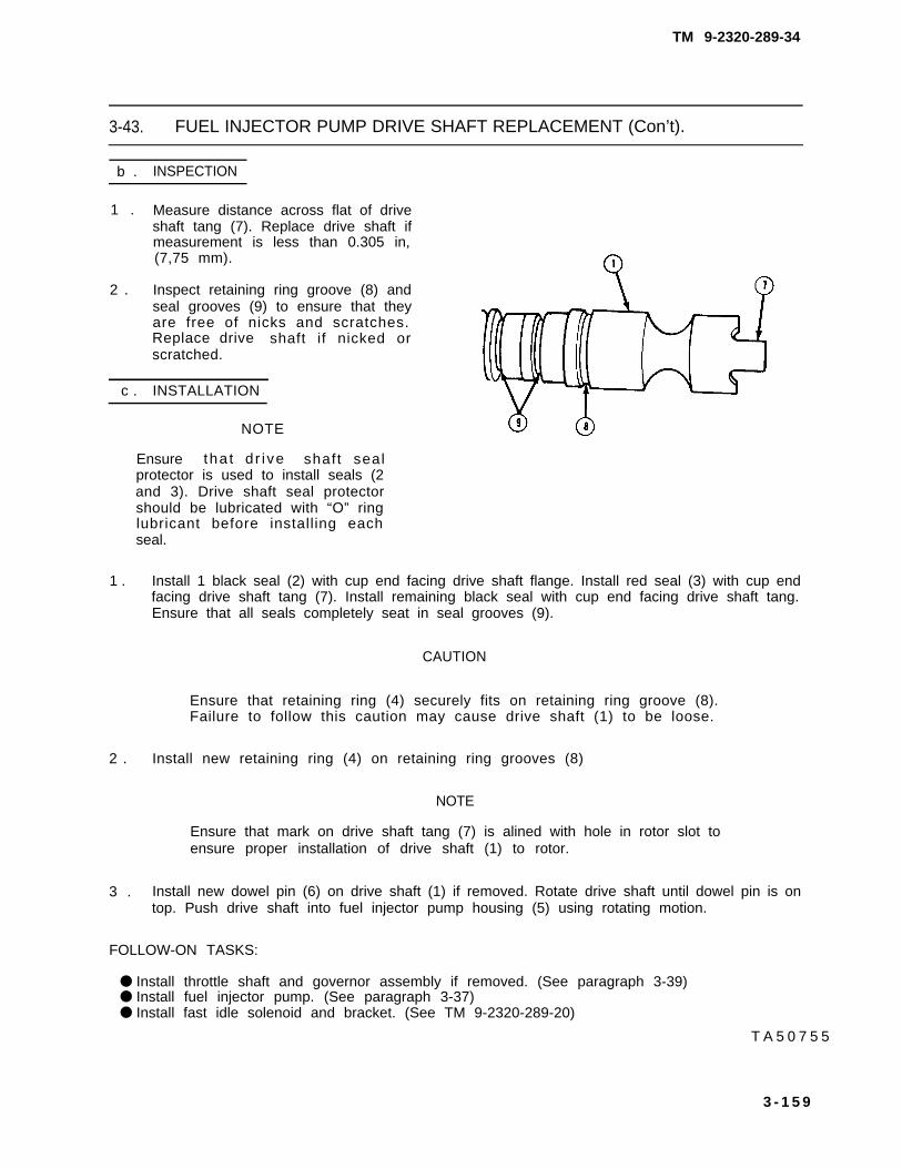
TM 9-2320-289-34
3-43. FUEL INJECTOR PUMP DRIVE SHAFT REPLACEMENT (Con’t).
b . INSPECTION
1 . Measure distance across flat of driveshaft tang (7). Replace drive shaft ifmeasurement is less than 0.305 in,(7,75 mm).
2 . Inspect retaining ring groove (8) andseal grooves (9) to ensure that theyare free of nicks and scratches.Replace drive shaft if nicked orscratched.
c . INSTALLATION
NOTE
Ensure tha t d r i ve shaft sealprotector is used to install seals (2and 3). Drive shaft seal protectorshould be lubricated with “O” ringlubricant before installing eachseal.
1 . Install 1 black seal (2) with cup end facing drive shaft flange. Install red seal (3) with cup endfacing drive shaft tang (7). Install remaining black seal with cup end facing drive shaft tang.Ensure that all seals completely seat in seal grooves (9).
CAUTION
Ensure that retaining ring (4) securely fits on retaining ring groove (8).Failure to follow this caution may cause drive shaft (1) to be loose.
2 . Install new retaining ring (4) on retaining ring grooves (8)
NOTE
Ensure that mark on drive shaft tang (7) is alined with hole in rotor slot toensure proper installation of drive shaft (1) to rotor.
3 . Install new dowel pin (6) on drive shaft (1) if removed. Rotate drive shaft until dowel pin is ontop. Push drive shaft into fuel injector pump housing (5) using rotating motion.
FOLLOW-ON TASKS:
● Install throttle shaft and governor assembly if removed. (See paragraph 3-39)● Install fuel injector pump. (See paragraph 3-37)● Install fast idle solenoid and bracket. (See TM 9-2320-289-20)
T A 5 0 7 5 5
3 - 1 5 9

TM 9-2320-289-34
3-44. FUEL INJECTOR PUMP TESTING AND TIMING.
This task covers: a. Testing b. Timing
INITIAL SETUP:
Equipment Condition MeterialslParts
● Fuel injector pump removed (if testing fuel • Calibration fluid (Item 13, Appendix B)injector pump). (See paragraph 3-37)
Tools/Test Equipment General Safety Instructions
● Torque wrench • Use only effective chip guarding andpersonnel protective equipment(goggles/shield, gloves, etc. ) whenusing compressed air.
a . TESTING
WARNING
Use only effective chip guarding and personnel protective equipment
1 .
2 .
3 .
4 .
5.
6 .
(goggles/shield, gloves, etc. ) when using compressed air, failure follow this warning may result in serious injury to personnel.
Drain all fuel from fuel injector pump into a suitable container.
Remove protective plug from fuel inlet pipe and connect compressedair hose.
Submerge fuel injector pump in clean calibration fluid, and apply 20 psi (138 kPa) of clean,dry, compressed air to fuel inlet pipe. Keep fuel injector pump submerged for 10 minutes toallow any trapped air to escape.
Check for hubbies, indicating leakage, after 10 minutes. If there is no leakage, reduce airpressure to 2 psi (14 kPa) for 30 seconds. If there still is no leakage, increase air pressure to20 psi (138 kPa). If there still is no leakage, fuel injector pump is ready for use.
If fuel injector pump leaks at any time after 10 minutes, note location of leakage. Remove fuelinjector pump from calibration fluid. Inspect leaking area for damage or looseness of mountinghardware. Perform appropriate maintenance task to repair leakage.
Disconnect compressed air hose from fuel inlet pipe and install plug.
b . T I M I N G
1 . Loosen 3 nuts retaining fuel injector pump to crankcase cover. Aline scribe marks on fuelinjector pump flange and crankcase cover. Tighten nuts to 30 Ib.-ft. (41 N.m).
FOLLOW-ON TASKS:
● Install fuel injector pump if removed, (See paragraph 3-37)
3 - 1 6 0

TM 9-2320-289-34
3-45. FUEL INJECTOR PUMP CALIBRATION.
This task covers: a. Testing Equipment e. CalibrationRequirements f. After Calibration
b. Preparation for Calibration g. Checking and Adjustingc. Adjustment Timing Markd. Preliminary Testing
INITIAL SETUP:
Equipment condition Materials/Parts
● Fuel injector pump removed. ● One face cam pin(See paragraph 3-37) . One timing cover gasket
. Calibration fluid (Item 13,● Fuel oil
Appendix B)
(Item 25, 26, or 27, Appendix B)● Pipe sealant (Item 61, Appendix B)
Tools/Test Equipment General Safety Instructions
Adjustable dc voltage source ●
Air-timing fixtureFuel flowmeter ●
Fuel injector pump test standOrifice fitting ●
ProtractorRetention torque adapterThrottle advance gageThrottle advance gage gasketTorque wrenchTransfer pressure tap adapter
Ensure that governor cover is installedbefore operation of fuel injector pump.DO NOT perform this procedure nearfire, flames, or sparks.Compressed air used for cleaningpurposes should never exceed 30 psi(207 kPa).
a . TESTING EQUIPMENT REQUIREMENTS
1 . Injector lines used for testing must be 0,093 in. (2.36 mm) inside diameter and 25 in.(63.5 cm) long.
2 . Test stand injector nozzles must include a 0.020 in. (0.5 mm) orifice plate.
3 . Calibration fluid temperature must be checked as close to transfer pump inlet as possible.Operating temperature should be 110°F-115°F (43.3°C-46.1°C).
4 . Fuel supply pressure to fuel injector pump must be set at 4.5-5.5 psi (31-38 kPa).
5 . The fuel injector pump test stand must include the following:
(a)
(b)
(c)
(d)
(e)
Self-alining zero-backlash drive coupling.
Digital tachometer.
Adjustable dc voltage source. Used to check operation of cold advance solenoid andshutoff solenoid.
Transfer pressure gage. Used to measure transfer pump, pressure. Operating rangeshould be 0-160 psi (0-1103 kPa), calibrated in 1 psi (6,895 kPa) increments.
Housing pressure gage. Used to measure housing pressure. Operating range should be0-30 psi (0-207 kPa).
3-161

TM 9-2320-289-34
3-45. FUEL INJECTOR PUMP CALIBRATION (Con’t).
(f) Temperature gage,
(9) Fuel supply valve,
(h) Orifice fitting. Located in fuel supply line between fuel supply pump and fuel supply valve.Orifice fitting is necessary to maintain correct calibration fluid temperature.
( i ) S h u t o f f v a l v e .
(j) Fuel supply pump.
(k) Fuel return line,
(1) Variable speed control.
b. PREPARATION FOR CALIBRATION
1.
2.
3.
4.
5.
6.
7.
8.
9.
100
11.
12.
Flush fuel injector pump with calibration fluid.
Check fuel injector pump drive shaft for freedom of rotation.
Engage fuel injector pump drive shaft on test stand drive coupling. Install fuel injector pump ontest stand mounting bracket with 3 washers and nuts, Tighten nuts to 30 Ib.-ft. (41 N.m).
Install transfer pump inlet connector (8).
Loosely connect 8 test stand injector lines (4) to fuel injector pump connectors.
Install transfer pressure tap adapter (3), Install shutoff valve (5) between transfer pressure tapand transfer pressure gage (6).
Remove 2 screws, timing cover, and timing cover gasket. Install throttle advance gage gasketand throttle advance gage (13) in timing cover opening. Set throttle advance gage to indicatezero. Discard timing cover gasket.
Connect housing pressure gage line (11 ) to housing pressure connector (12).
Connect fuel supply line (9) to transfer pump inlet connector (8).
NOTE
Ensure that fuel return line (2) is connected so that fuel is directedthrough flowmeter.
Connect test stand fuel return line (2) to fuel injector pump return line fitting (1).
Connect positive test lead (14) from adjustable dc voltage source (16) to shutoff solenoidterminal. Connect ground lead (15) to mounting plate.
Open fuel supply valve (1 O) and turn to test stand “ON” position. Allow fuel to bleed fromloosened fittings of test stand injector lines (4) for several seconds, then tighten all fittings.
3 - 1 6 2

TM 9-2320-289-34
3-45. FUEL INJECTOR PUMP CALIBRATION (Con’t).
T A 5 0 7 5 6
3-163

TM 9-2320-289-34
3-45. FUEL INJECTOR PUMP CALIBRATION (Con’t).
c . ADJUSTMENT
1 .
2 .
3 .
4 .
5 .
NOTE
Adjustment in step 1 should be made during applicable step, Adjustmentsin steps 2-5 should be made after all calibration is completed, unlessotherwise stated,
If any throttle advance gage (13)reading is not correct, adjust positionof servo adjusting screw (22) to obtainproper reading. After all testing iscomplete, apply pipe sealant to servoadjusting screw.
If any flowmeter reading is too low,replace metering screw with a smallermetering screw. (See paragraph3-39)
If any flowmeter reading is too high,replace metering screw with a largermetering screw. (See paragraph3-39)
If any housing pressure reading is notcorrect, test fuel injector pump. (Seeparagraph 3-44) If no leaks aredetected, remove hydraulic head andcheck for incorrectly assembledcomponents. (See paragraph 3-42)
If any transfer pump pressure readingis not correct, remove transfer pumpblades and regulator and check forincorrectly assembled components.(See paragraph 3-41 )
d . PRELIMINARY TESTING
1. Set test stand supply pump boost pressure at 4.5-5.5 psi (31-38 kpa).
NOTE
Test specifications refer to engine rpm. Most test stand tachometersregister fuel injector pump rpm, which is half of engine rpm. Ensure thatproper adjustments are made during calibration.
2 . Set rpm at 2000, with throttle lever (17) in wide open throttle position. Allow fuel injector pump torun for 10 minutes to clear remaining air from system and bring fuel injector pump to operatingtemperature.
3. Set rpm at 2000, with throttle lever (17) in wide open throttle position. Set transfer pressure gage(6) to indicate 58-64 psi (400-441 kPa). Flowmeter reading must be 225-375 cc, PerformADJUSTMENT if necessary.
T A 5 0 7 5 7
3-164 Change 2

TM 9-2320-289-34
3-45. FUEL INJECTOR PUMP CALIBRATION (Con’t).
4 , Set rpm at 600, with throttle lever (17) in low idle position. Housing pressure gage (7) readingshould be 8–12 psi (55–83 kPa).
5 . Set adjustable dc voltage source (16) to 9.0 volts. Connect positive test lead (14) to coldadvance solenoid terminal. Housing pressure gage (7) reading should be 0-1 psi (0-6.9 kPa).Disconnect positive test lead.
6 . Set rpm at 600, with throttle lever (17) in low idle position. Flowmeter reading must be12.5-16.5 cc. If flowmeter reading is not correct, perform step 7.
TA50758
3-165

TM 9-2320-289-34
3-45. FUEL INJECTOR PUMP CALIBRATION (Con’t).
WARNING
Ensure that governor cover is installed before operation of fuel injectorpump. Pressurized fuel may cause injury to personnel and/or damage toequipment.
7 . R e m o v e governor cover. (Seeparagraph 3-38) Place fuel injectorpump in low idle position, Rotateadjusting nut (24) as needed toobtain specification. Install governorcover and repeat step 6.
8 . Set rpm at 400, with throttle lever (17) in low idle position. Connect positive test lead (14) toshutoff solenoid terminal. Listen for “clicking” sound from shutoff solenoid, indicating properoperation.
9 . Shut off fuel supply valve (1 O) and check vacuum gage for minimum lift of 18 in. Hg. Turn onfuel supply valve.
TA50759
3 - 1 6 6

TM 9-2320-289-34
3-45. FUEL INJECTOR PUMP CALIBRATION (Con’t).
10. Set mechanical light load advance asfollows:
(a)
(b)
(c)
Perform paragraph 3-39,INSTALLATION, step 10.
Place throttle lever (17) in wideopen throttle position. Rotateface cam (19) to maximum liftposition in contact with camroller (23) on rocker lever (21).
Set rpm at 2000. Adjust positionof servo adjusting screw (22) toobtain 0.5-1.5 degrees camadvance indication on throttleadvance gage (13).
3-167

TM 9-2320-289-34
3-45. FUEL INJECTOR PUMP CALIBRATION (Con’t).
(d)
(e)
Set rpm at 1500 and rotatethrottle lever (17) to obtain afIowmeter reading of 21,5-23.5 cc. Rotate face cam (19)to obtain 2.5-4.5 degrees camadvance indication on throttleadvance gage (13).
Repeat paragraph 3-39, INSTAL-LATION, step 10.
11. Check face cam retention torque asfollows:
(a) Turn test stand to “OFF”position. Drive out and discardface cam pin (20).
NOTE
Scribe mark will provide a reference point for checking face cam (19)movement.
(b) Position throttle lever (17) against low idle stop and scribe a line on throttle shaft housingin line with rear edge of face cam (19),
(c) Install retention torque adapter over throttle shaft end and engage face cam (19).
(d) Apply 22 lb.-in. (2.5 N.m) to face cam (19). Face cam must not rotate on throttle shaft.
(e) If rotation of face cam (19) occurs at or below 22 lb.-in. (2.5 N.m), loosen screw (18)and remove face cam. Inspect throttle shaft for damage. If throttle shaft is damaged,replace. (See paragraph 3-39) If throttle shaft is not damaged, replace face cam andscrew, Repeat steps 10 and 11.
1 2 . Set total throttle travel as follows:
(a)
(b)
(c)
(d)
Turn test stand to “ON” position.
Set rpm at 1500 and rotate throttle lever (17) to obtain a flowmeter reading of19.5-25.5 CC.
Lock throttle lever (17) in position and install protractor (25) onto rocker lever (21). Alinezero-degree mark with center of rib on rocker lever.
Unlock throttle lever (17) and rotate to wide open throttle position, Adjust maximum travelscrew to indicate 56.5 degrees on protractor (25).
TA50761
3-168

TM 9-2320-289-34
3-45. FUEL INJECTOR PUMP CALIBRATION (Con’t).
(e)
(f)
Place throttle to low idle positionand aline zero-degree mark onprotractor (25) with center of ribon rocker lever (21).
Rotate throttle lever (17) to wideopen throttle position. Readingon protractor (25) should be73-82 degrees.
e . CALIBRATION]
1 . Set rpm to 1500, with throttle lever(17) in wide open throttle position.Disconnect positive test lead (14)from -- shutoff solenoid terminal.Maximum flowmeter reading shouldbe 4.0 cc. Connect positive test leadto shutoff solenoid terminal.
3-169

TM 9-2320-289-34
3-45. FUEL INJECTOR PUMP CALIBRATION (Con’t).
2 . Set rpm to 150, with throttle lever (17) in wide open throttle position. Minimum flowmeterreading should be 35.0 cc. Open shutoff valve (5). Minimum transfer pressure gage (6)reading should be 12 psi (83 kPa). Close shutoff valve.
3 . Set rpm to 600, with throttle lever (17) in low idle position. Flowmeter reading should be12.5-16.5 cc. Minimum throttle advance gage (13) reading should be 1.5 degrees.
4 . Adjust position of servo adjustingscrew (22) to obtain 2.25 degreescam advance indication on throttleadvance gage (13). Disconnectpositive test lead (14) from shutoffsolenoid terminal, Connect positivetest lead to cold advance solenoidterminal. Housing pressure gage (7)reading should 0-1 psi(0-6.9 kPa). Disconnect positive testlead.
5 . Set rpm to 1500 and rotate throttlelever (17) to obtain a flowmeterreading of 21 .5-23.5 cc. Throttleadvance gage (13) reading should be2.5-4.5 degrees. Housing pressuregage (7) reading should be 8-12 psi(55-83 kPa).
6 . Set rpm to 2000, with throttle lever(17) in wide open throttle position.Flowmeter reading s h o u l d b e47.5-51.5 cc. Throttle advance gage(13) reading should be 0.5-2.5degrees. Housing pressure gage (7)reading should be 8-12 psi(55-83 kPa).
7 . Set rpm to 3200, with throttle lever(13) reading should be 4.25-6.758-12 psi (55-83 kPa).
(17) in wide open throttle position. Throttle advance gagedegrees. Housing pressure gage (7) reading should be
CAUTION
Ensure that throttle lever (17) remains in low idle position no longer thanlength of time required to record gage readings. Failure to follow thiscaution may result in damage to fuel injector pump.
8 . Place throttle lever (17) in low idle position, Maximum throttle advance gage (13) readingshould be 10.0 degrees. Housing pressure gage (7) reading must be 8-12 psi (55-83 kPa).
9 . Set rpm to 4000, with throttle lever (17) in wide open throttle position. Minimum flowmeterreading should be 40.0 cc.
TA50763
3-170

TM 9-2320-289-34
3-45. FUEL INJECTOR PUMP CALIBRATION (Con’t).
10. Open shutoff valve (5), Set rpm to 4400, with throttle lever (17) in wide open throttle position.Maximum flowmeter reading must be 4.0 cc. Transfer pressure gage (6) reading must be125 psi (862 kPa). Close shutoff valve,
f. AFTER CALIBRATION
1. Return test stand to “OFF” position.
2. Disconnect ground lead (15) and positive test lead (14),
3. Shut off fuel supply valve (10).
4, Disconnect all fuel and gage connections from fuel injector pump.
5. Remove throttle advance gage (13), Discard throttle advance gage gasket. Install new timingcover gasket and timing cover with 2 screws.
6. Remove 3 nuts and washers and fuel injector pump from test stand mounting bracket.
TA50764
3-171

TM 9-2320-289-34
3-45. FUEL INJECTOR PUMP CALIBRATION (Con’t).
g. CHECKING AND ADJUSTING TIMING MARK
1. Loosen 2 adjusting screws (31) and set air-timing fixture (26) to 0,25-0,75 degrees, Tightenadjusting screws,
2. Rotate fuel injector pump drive shaft until locating pin (34) is at the 7 o’clock position.
3. Install air-timing fixture (26) on fuel injector pump, ensuring that locating pin (34) engagesmating hole (30). Secure air-timing fixture by tightening knurled screw (29) finger tight againstfuel injector pump flange (33).
NOTE
#1 discharge fitting (32) can be identified by a number “1“ cast on fuelinjector pump housing.
4. Supply 60-100 psi (414-689 kPa) of dry, filtered air to #1 discharge fitting (32).
NOTE
The point when cam rollers contact cam ring is point when injectionbegins at #l discharge fitting (32).
5. Loosen knurled screw (29) and rotate air-timing fixture (26) counterclockwise until cam rollerscan be felt making contact with cam ring. Rotate air-timing fixture back to its original position.
TA50765
3-172

TM 9-2320-289-34
3-45. FUEL INJECTOR PUMP CALIBRATION (Con’t).
6.
7.
8.
9.
10.
11.
12.
Repeat step 5 several times to get a definite feel of when rollers first make contact with camring.
Rotate air-timing fixture (26) counterclockwise until cam rollers can be felt making contact withcam ring, Tighten knurled screw (29).
Remove marking scribe adapter (27) and spring from air-timing fixture (26) and install opticalsight gage (28).
Sight through optical sight gage (28) and check for position of existing timing mark on fuelinjector pump flange (33). If existing mark is not in line with timing line on optical sight gage,perform steps 10-15. If existing mark is correct, perform steps 13-15.
Remove optical sight gage (28) from air-timing fixture (26). Loosen knurled screw (29) andremove air-timing fixture.
CAUTION
Drive shaft and pilot area of fuel injector pump must be covered with aclean rag during step 11. Failure to follow this caution may result indamage to drive shaft bearings and seals.
File off old timing mark.
Repeat steps 2, 3, and 5 through 7. Tap marking scribe adapter (27) to place a new timingmark on fuel injector pump flange (33). Remove air-timing fixture (26) and disconnect airsupply from #1 discharge fitting (32).
3-173

TM 9-2320-289-34
3-45. FUEL INJECTOR PUMP CALIBRATION (Con’t).
13.
14.
15.
WARNING
● Diesel fuel is flammable, DO NOT perform this procedure near fire,flames, or sparks.’ A fire extinguisher must be on hand in work area.Failure to follow this warning may result in serious injury or death topersonnel,
● Compressed air used for cleaning purposes should never exceed 30 psi(207 kPa). Use only effective chip guarding and personnel protectiveequipment (goggles/shield, gloves, etc.). Failure to follow this warningmay result In serious injury to personnel.
Clean exterior of fuel injector pumpwith fuel oil and dry with compressedair.
Apply pipe sealant to servo adjustingscrew (22).
Install new face cam pin (20),
FOLLOW-ON TASKS:
● Install fuel injector pump. (See paragraph 3-37)
TA50766
3-174

TM 9-2320-289-34
3-46. TRANSMISSION VACUUM VALVE REPLACEMENT.
This task covers: a, Removal b. Installation
INITIAL SETUP:
Equipment Condition Tools/Test Equipment
● Air cleaner removed. ● Valve gage block, J-33043(See TM 9-2320-289-20) ● Vacuum gage
● Vacuum pump
a. REMOVAL
NOTE
If only adjusting transmission vacuum valve (5), perform REMOVAL,step 1, and INSTALLATION, steps 2-7.
1. Disconnect vacuum hose connector (2) from transmission vacuum valve (5).
2. Remove 2 screws (6) and transmission vacuum valve from fuel injector pump (1).
TA50767
3 - 1 7 5

TM 9-2320-289-34
3-46. TRANSMISSION VACUUM VALVE REPLACEMENT (Con’t).
b. INSTALLATION
NOTE
Transmission vacuum valve (5) must always be adjusted when it isinstalled.
1. Install transmission vacuum valve (5) on fuel injector pump (1) with 2 screws (6). DO NOT fullytighten screws. Transmission vacuum valve must be free to rotate on fuel injector pump.
2. Attach vacuum source to lower vacuum nipple (4). Attach vacuum gage to upper vacuumnipple (3), Bring vacuum down to 20 in. Hg.
TA50768
3-176

TM 9-2320-289-34
3-46. TRANSMISSION VACUUM VALVE REPLACEMENT (Con’t).
3. Insert valve gage block (9) betweengage boss (1 O) and wide-open stopscrew (8) on throttle lever (7). Rotateand hold throttle lever against valvegage block.
4. Loosen 2 screws (6), if not alreadyloose. Slowly rotate transmissionvacuum valve (5) clockwise (towardfront of truck) until vacuum gagereads 8 in. Hg. Hold transmissionvacuum valve in this position, andtighten 2 screws.
5. Check adjustment by releasingthrottle lever (7) then rotating throttlelever against valve gage block (9). Ifvacuum gage does not read 8 in. Hg,loosen 2 screws (6) and repeat steps2-5.
6. Disconnect vacuum source and vacuum gage.
7. Connect vacuum hose connector (2) to transmission vacuum valve (5).
FOLLOW-ON TASKS:
● Install air cleaner. (See TM 9-2320-289-20)
TA50769
3-177

TM 9-2320-289-34
3-47. BROKEN GLOW PLUG REMOVAL.
This task covers: a. Removal
INITIAL SETUP:
Equipment Condition General Safety Instructions
l Fuel injector nozzle at broken glow plug . Compressed air used to remove glowremoved. (See paragraph 3-5) plug should never exceed 30 psi
(207 kPa).
a. REMOVAL
1. Place finger over fuel injector nozzle port. Rotate torsional damper to raise piston in affectedcylinder to “Top Dead Center.”
2. Unscrew and move glow plugprechamber.
Compression will change when “Top Dead Center” is reached,
back and forth to break off glow plug tip into cylinder head
WARNING
Compressed air used to remove glow plug should never exceed 30 psi(207 kPa). Use only effective chip guarding and personnel protectiveequipment (goggles/shieid, gloves, etc.). Failure to follow this warningmay result in serious injury to personnel.
3. Direct compressed air into glow plug port to remove glow plug tip through fuel injector nozzleport,
4. If preceding procedure does not remove broken glow plug, remove cylinder head. (Seeparagraph 3-7)
FOLLOW-ON TASKS:
● Install fuel injector nozzle. (See paragraph 3-27)● lnstall new glow plug. (See TM 9-2320-289-20)
3-178

TM 9-2320-289-34
Pages 3-175 through 3-177 have been rescinded,
3-47. BROKEN GLOW PLUG REMOVAL.
This task covers: a. Removal – Method #1 b. Removal – Method #2
INITIAL SETUP:
Equipment Condition General Safety Instructions
• All fuel injector nozzles removed. • Compressed air used to remove glow(See paragraph 3-5) plug should never exceed 30 psi
(207 kPa).
WARNING
Failure to remove ail eight fuel injector nozzles before rotating crankshaftmay result in injury to personnel.
a . REMOVAL – METHOD #1
1. Place finger over fuel injector nozzle port, Rotate torsional damper to raise piston in affectedcylinder to “Top Dead Center. ” Compression will change when “Top Dead Center” is reached.
2. Unscrew and move glow plug back and forth to break off glow plug tip into cylinder headprechamber.
WARNING
Compressed air used to remove glow plug should never exceed 30 psi(207 kPa). Use only effective chip guarding and personnel protectiveequipment (goggles/shield, gloves, etc.). Failure to follow this warning mayresult in serious injury to personnel.
3. Direct compressed air into glow plug port to remove glow plug tip through fuel injector nozzleport.
4. If preceding procedure does not remove broken glow plug, remove cylinder head. (Seeparagraph 3-7)
3-178 Change 2

TM 9-2320-289-34
3-47. BROKEN GLOW PLUG REMOVAL (Con’t).
b. REMOVAL – METHOD #2
1. Place finger over fuel injector nozzle port. Rotate torsional damper to raise piston in affectedcylinder to “Top Dead Center. ” Compression will change when “Top Dead Center” is reached.
2. Coil one end of flat 18 in. (45.7 cm) piece of tie wire to match size of injector hole.
3. Place wire coiled end over preheater to combustion chamber hole to prevent glow plug tip fromfalling into combustion chamber,
4. Using long nose pliers with 90° bend inserted through injector nozzle hole, grasp glow plug tip,break it off, and remove pieces from prechamber.
5. If preceding procedure does not remove broken glow plug, remove cylinder head. (Seeparagraph 3-7)
FOLLOW-ON TASKS:
• Install fuel injector nozzle. (See paragraph 3-27)• Install new glow plug. (See TM 9-2320-289-20)
Change 2 3-178.1/(3-178.2 blank)

TM 9-2320-289-34
Sect ion IV. COOLING SYSTEM MAINTENANCE
3-48. WATER PUMP REPLACEMENT.
This task covers: a. Removal b. Installation
INITIAL SETUP:
Equipment Condition
●
●
●
●
Cooling system drained (if being performedin truck). (See TM 9-2320-289-20)Fan shroud removed (if being performedin truck). (See TM 9-2320-289-20)Right side alternator bracket removed (allexcept Ml 01 O). (See TM 9-2320-289-20)Power steering pump removed (if beingperformed in truck). (See TM 9-2320-289-20)
Tools/Test Equipment
● Torque wrench
Materials/Parts
●
●
●
●
One water pump gasketCarburetor cleaning compound(Item 15, Appendix B)Anaerobic sealing compound(Item 59, Appendix B)Pipe sealant (Item 61, Appendix B)
General Safety Instructions
● Avoid skin contact with anaerobicsealing compound.
● Carburetor cleaning compound ishighly flammable. Keep away fromopen flame.
NOTE
Perform step 1 for M1010 only, ifengine is in truck.
1. Remove 2 nuts at upper part ofbracket (2). Loosen nut (3), androtate compressor (1) and bracketoff water pump studs.
TA50770
3-179

TM 9-2320-289-34
3-48. WATER PUMP REPLACEMENT (Con’t).
2. Loosen clamp and disconnect crankcase depression regulator valve hose from oil filler tube(4). Remove 2 nuts (12), oil filler tube, and grommet (11) from water pump plate (5).
3. Loosen clamp (7) and disconnect thermostat bypass hose (6) from water pump (8). Loosenclamp (9) and disconnect radiator outlet hose (1 O) from water pump.
●
●
4. Remove
NOTE
Ensure that a suitable container is used to catch coolant as water pumpplate (5) ● nd water pump (8) are removed.
Ensure that position of all bolts, studs, and screws is noted forInstallation.
2 oil filler tube studs (16), 4 bolts (17), stud (23), 2 screws (24), long screw (21),long bolt (22), and 2 studs (13), Remove water pump plate (5) and water pump (8) fromcrankcase cover (18).
5. Remove 7 bolts (19) and separate water pump (8), water pump gasket (20), and water pumpplate (5). Remove nipple (15) and plug (14) if damaged or if replacing water pump. Discardwater pump gasket.
TA60771
3-180

TM 9-2320-289-34
3-48. WATER PUMP REPLACEMENT (Con’t).
WARNING
Carburetor cleaning compound is highly flammable. Keep away from openflame, Failure to follow this warning may result in serious injury or death topersonnel,
6. Clean anaerobic sealing compound from all sealing surfaces. Clean oil from all surfaces withcarburetor cleaning compound, Clean pipe sealant from crankcase cover (18) and threads ofall bolts, screws, and studs,
b . INSTALLATION
1. Install nipple (15) and plug (14) on water pump (8) with pipe sealant, if removed. Assemblewater pump plate (5), new water pump gasket (20), and water pump with 7 bolts (19). Tightenbolts to 20 Ib.-ft. (27 N.m).
TA50772
3-181

TM 9-2320-289-34
3-48. WATER PUMP REPLACEMENT (Con’t).
3.
4.
5.
6.
WARNING
Avoid skin contact with anaerobic sealing compound. Immediately washoff skin if contact is made. Failure to follow this warning may result ininjury to personnel.
2. Apply anaerobic sealing compound(25) to crankcase cover (18) inpattern shown.
Apply pipe sealant to threads of bolts (17). Apply pipe sealant to oil filler tube studs (16) andstud (23) on portion of threads installed on crankcase cover (18).
Install water pump (8) and water pump plate (5) on crankcase cover (18) with long bolt (22),long screw (21 ), 2 studs (13), 2 screws (24), stud (23), 4 bolts (17), and 2 oil filler tube studs(16). Tighten bolts (17) and stud (23) to 35 Ib.-ft. (47 N.m). Tighten all other bolts, studs, andscrews to 20 Ib.-ft. (27 Nom).
Connect radiator outlet hose (1 O) to water pump (8) and tighten clamp (9). Connectthermostat bypass hose (6) to water pump and tighten clamp (7).
Install grommet (11 ) on water pump plate (5). Install oil filter tube (4) on water pump plate with2 nuts (1 2). Connect crankcase depression regulator valve hose to oil filler tube and tightenclamp.
TA50773
3-182

TM 9-2320-289-34
3-48. WATER PUMP REPLACEMENT (Con’t).
TA50774
3 - 1 8 3

TM 9-2320-289-34
3-48. WATER PUMP REPLACEMENT (Con’t).
NOTE
Perform step 7 for Ml 010 only.
7. Position bracket (2) and compressor(1) on water pump studs, Tighten nut(3). Install 2 nuts at upper part ofbracket.
FOLLOW-ON TASKS:
● Install power steering pump (if being performed in truck). (See TM 9-2320-289-20)● Install right side alternator bracket if removed. (See TM 9-2320-289-20)● Install fan shroud (if being performed in truck). (See TM 9-2320-289-20)● Fill cooling system (if being performed in truck). (See TM 9-2320-289-20)
TA50775
3-184

TM 9-2320-289-34
CHAPTER 4ELECTRICAL SYSTEMS MAINTENANCE
4-1. ELECTRICAL SYSTEMS MAINTENANCE INDEX.
ParagraphNumber
4-2.4-3.4-4.4-5.4-6.
4-7.4-8.4-9.4-9.1.
4-10.4-11.4-12.
4-13.4-14.
Procedures
Alternator Testing and Repair (All Except M1010) . . . . . . . . . . . . .Alternator Testing and Repair (M1010) . . . . . . . . . . . . . . . . . . . . . .Current/Voltage Regulator and Relay Replacement (M1010) .Starter Testing and Repair. . . . . . . . . . . . . . . . . . . . . . . . . . . . . . .Instrument Panel Wiring Harness and ExtensionReplacement . . . . . . . . . . . . . . . . . . . . . . . . . . . . . . . . . . . . . . . . . . . .Front Wiring Harness Replacement . . . . . . . . . . . . . . . . . . . . . . . . . .Body Wiring Harness Replacement . . . . . . . . . . . . . . . . . . . . . . . . . .Taillight Wiring Harness Replacement (M1010 and M1031) ..Rear Fender Wiring Harness Replacement(M1028A2 and M1028A3) . . . . . . . . . . . . . . . . . . . . . . . . . . . . . . . . .Engine Wiring Harness Replacement . . . . . . . . . . . . . . . . . . . . . . . .Glow Plug Wiring Harness Replacement.... . . . . . . . . . . . . . . . . . . . . . . . . .Cab Heater Control, Engine Diagnostic, and Open DoorBuzzer Wiring Harnesses Replacement . . . . . . . . . . . . . . . . . . . . . .Dimmer and ignition Switches Replacement . . . . . . . . . . . . . . . . . .Directional Signal Switch Replacement . . . . . . . . . . . . . . . . . . . . . . .
PageNumber
4-24-144-244-26
4-384-534-604-66
4-68.14-694-83
4-864-914-94
Change 2 4-1

TM 9-2320-289-34
4-2. ALTERNATOR TESTING AND REPAIR (ALL EXCEPT M1010).
This task covers: a. Alternator Output Testing d. Component Testingb. Disassembly e. Assemblyc. Cleaning and Inspection
INITIAL SETUP:
Materials/Parts Too/s/Test Equipment
One generator positive (+) terminal ●
package ●
One generator negative (-) terminal ●
package ●
One generator relay terminal package ●
Crocus cloth (Item 18, Appendix B)
500 amp test standBelt tensioning gageMultimeterTest lightTorque wrench
Dry cleaning solvent (lterm 23, Appendix B) Manual ReferencesGrease (Item 36, Appendix B) ● TM 9-214Masking tape (Item 68, Appendix B)Insulating varnish (Item 71, Appendix B)
General Safety Instructions
• Compressed air used for cleaning purposes should never exceed 30 psi (207 kPa).● Dry cleaning solvent is flammable and must not be used near open flame. Use only in a
well-ventilated area.
a. ALTERNATOR OUTPUT TESTING
1.
2.
3.
4.
5.
6.
4 - 2
Mount pivot arm of 500 amp test stand to high speed side, and screw mounting flange adapter topivot arm, Connect pulley drive shaft with shaft of high speed head. Screw pulley drive shaft tomounting flange adapter,
Mount alternator to generator/starter mounting bracket on 500 amp test stand. Connect“ V“ belt from 500 amp test stand pulley to alternator pulley. Adjust belt tension, (See AppendixD)
Connect cable from alternator “ BAT” terminal to 500 amp test stand “G+” terminal, Connectcable from alternator ground terminal to 500 amp test stand “G-” terminal,
Make a jumper wire with an insulated female spade terminal on one end and ring terminal onother end. Jump wire from alternator “ NO. 2” terminal to alternator “ BAT” terminal.
Using test light, connect one probe to alternator “ BAT” terminal and other probe to alternator“ NO, 1“ terminal.
Set 500 amp test stand as follows:
(a)
(b)
(c)
(d)
(e)
DC ammeter switch to “x10”
DC voltmeter range switch to “x2”
DC voltmeter select switch to “ BAT”
Tachometer switch to “ DIRECT DRIVE”
Battery switch and master load switch to “OFF”
Change 2

TM 9-2320-289-34
4-2. ALTERNATOR TESTING AND REPAIR (ALL EXCEPT M1010) (Con’t).
7. Turn 500 amp test stand master power switch and master load switch to “ON” and batteryswitch to “ 12V DC. ” Green lamp on 500 amp test stand must illuminate.
NOTE
When tachometer reaches 6500 rpm, test light should go out to indicateproper charging from alternator.
8. Raise speed until tachometer reads 6500 rpm.
9. Set one 100 amp load switch on 500 amp test stand to “ON. ”
10. Readings should be 14.0 volts and 90-100 amps. If readings are not correct, repair alternator.
b. DISASSEMBLY
1. Remove 4 bolts (4) and separate end frame (1) and stator frame (3) from drive end housing(2) .
2. Place a piece of tape over end frame (1) bearing to prevent entry of dirt and foreign material ifbearing will not be replaced.
CAUTION
Stator (5)to followoutput.
3. Remove 3 nuts
should be handled with caution to avoid damage to coils. Failurethis caution may result in shorted stator and low alternator
(6) and stator (5) from end frame (1).
TA50776
4-3

TM 9-2320-289-34
4-2. ALTERNATOR TESTING AND REPAIR (ALL EXCEPT M1010) (Con’t).
4. Remove nut (16), “ R“ terminal bar (19), fiber insulator (30), plastic insulator (29) and “R“terminal stud (28). Discard all components.
5. Remove 3 insulated screws (11), resistor (13), diode trio (20), brush holder assembly (9), andvoltage regulator (12).
6. Remove screw (21 ) and disconnect capacitor lead (23) from rectifier bridge (7). Removescrew (24), wire retainer, and capacitor (8).
7, Remove screw (22) and rectifier bridge-to-regulator jumper wire (10).
8. Remove nut (17), nut (14), bus bar (15), and fiber insulator (25). Remove battery positive (+)terminal (26) and plastic insulator (27) from outside of end frame (1). Discard all components.
9. On outside of end frame (1), remove nut, Iockwasher, flat washer, and fiber insulator fromnegative (-) terminal stud (18). Discard all components.
TA50777
4-4

TM 9-2320-289-34
4-2. ALTERNATOR TESTING AND REPAIR (ALL EXCEPT M1010) (Con’t).
10. Remove rectifier bridge (7) and remove negative (-) terminal from rectifier bridge. Removenegative (-) terminal plastic insulator and rectifier bridge fiber insulator.
11. Press out end framefrom end frame (1)toward inside.
CAUTION
bearing (31)by pressing
Rotor (32) should not be securedin vise at slip rings (42) on shaft.Failure to follow this caution mayresult in damage to slip rings orshaft.
12. Place rotor (32) in soft-jawed vise.Remove nut (40), wavewasher (39),pulley (38), fan (37), and collar (36)from drive end housing (2).
13. Remove rotor (32).
NOTE
Dowel pin (35) may be found Inend frame (1).
14. Remove 3 screws (41), plate (33), and drive end bearing (34) from drive end housing (2).Remove dowel pin (35) if damaged.
4 - 5

TM 9-2320-289-34
4-2. ALTERNATOR TESTING AND REPAIR (ALL EXCEPT M1010) (Con’t).
c . CLEANING AND INSPECTION
WARNING
1.
2.
3.
4.
5.
6.
7.
8.
9.
● Dry cleaning solvent P-D-680 is toxic and flammable. Always wearprotective goggles and gloves and use only in a well-ventilated area.Avoid contact with skin, eyes, and clothes and DO NOT breathe vapors.DO NOT use near open flame or excessive heat. The solvent’s flashpoint is 100°F-138°F (38°C-59°C). if you become dizzy while usingcleaning solvent, immediately get fresh air and medical help. if solventcontacts eyes, immediately wash your eyes with water and get medicalaid.
● Compressed air used for cleaning purposes should never exceed 30 psi(207 kPa). Use only effective chip guarding and personnel protectiveequipment (goggles/shield, gloves, etc.). Failure to follow this warningmay result in serious injury to personnel.
Clean all metal parts except regulator, rectifier bridge, stator assembly, rotor, and bearingassemblies in dry cleaning solvent. Dry with compressed air.
inspect brush holder assembly for damage. Replace brush holder assembly if damaged or ifbrushes are worn to a length of 0.630 in. (16 mm) or less, If brushes are to be reused, cleanwith a soft dry cloth.
Inspect insulating sleeves on insulated screws for splits or wear. Replace if split or worn.
Inspect end frame bearing for damage in accordance with TM 9-214. If bearing is damaged, orif grease supply is used up, replace bearing. Do NOT lubricate bearing.
Inspect slip ring end of rotor shaft for overheating or scoring. If there are signs of overheatingor scoring, replace end frame bearing and rotor.
Inspect drive end bearing for damage in accordance with TM 9-214. Inspect seal in plate fordamage. If drive end bearing or seal are damaged, replace both bearing and plate.
Inspect stator assembly and rotor winding for burned insulation. Burned insulation appears as adark or blackened wiring. A strong acrid odor will be apparent. Replace stator assembly orrotor if either looks burned.
Inspect stator assembly terminal connector for corrosion or breaks. If corroded or broken,reploace stator.
Inspect windings on stator assembly for chipped insulation. Repair stator insulation withinsulating varnish if possible. Replace stator if insulator cannot be repaired with insulatingvarnish.
4-6

TM 9-2320-289-34
4-2. ALTERNATOR TESTING AND REPAIR (ALL EXCEPT M1010) (Con’t).
10. Inspect rotor slip rings (42) forscoring, wear, or pitting.
(a)
(b)
If rings are dirty, clean with 400grain or finer crocus cloth. Spinrotor and hold crocus clothagainst slip rings until clean.
If scored, worn, or pitted, truerings in lathe to 0.002 in.(0.05 mm). Finish with 400 grainor finer crocus cloth. Blow awayall dust.
11. Inspect end frame and drive endhousing for damage. Replace ifdamaged.
d. COMPONENT TESTING
1. Using test light or ohmmeter, check continuity betweenwith scale of 200 ohms or less. If there is no continuity,
2. Using test light or ohmmeter, checkcontinuity between each statorassembly lead and stator frame (3). Ifcontinuity is not infinite, replacestator assembly.
each stator assembly lead terminalreplace stator assembly.
TA50779
4 - 7

TM 9-2320-289-34
4-2. ALTERNATOR TESTING AND REPAIR (ALL EXCEPT M1010) (Con’t).
3.
4.
5.
6.
7.
Connect voltmeter (44) and fastcharger (43) to a 12 volt battery.
Connect voltage regulator (12) andtest lamp (46) as shown.
Observe battery (45) polarity. Testlamp (46) should be on.
Turn on fast charger (43) and slowlyincrease charge rate. Observevoltmeter (44), Test lamp (46) shouldgo out at voltage regulator (12)setting. Voltage regulator settingshould be a minimum of 13,5 voltsand a maximum of 15,5 volts,
Remove test lamp (46), anddisconnect voltmeter (44) and fastcharger (43).
8. Using self-powered test light or ohmmeter, check for continuity between slip rings. If continuity isnot present, replace rotor.
9. Using self-powered test light or ohmmeter, check for continuity between each slip ring and rotorshaft. If there is continuity, replace rotor.
10. Check for rotor short circuits or extreme resistance by connecting a battery and ammeter inseries with edges of 2 slip rings. Ammeter reading at 70°F (21°C) should be 4.5-5.0 amps, Ifammeter reading is not with specification, replace rotor.
TA50780
4 - 8 Change 2

TM 9-2320-289-34
4-2. ALTERNATOR TESTING AND REPAIR (ALL EXCEPT M1010) (Con’t).
11. Connect ohmmeter, with a 1 1/2 voltcell, to single connector (47) and to 1of 3 connectors (48) on diode trio(20). Set ohmmeter to lowest rangescale. Observe reading. Reverseohmmeter l e a d s t o same 2connectors. In one direction,readings should be infinite, in otherdirection readings should be finite.
12.
13.
14.
Place rectifier bridge (7) onnonconductive work surface, Slightlyseparate 6 tabs at 3 diode terminalsfor testing. Connect an ohmmeter tonegative heat sink and to each of 3terminals on negative (-) heat sinkside. Record readings. Reverseconnectors. One test should giveinfinite readings and other test shouldgive finite readings.
Check 3 terminals on positive (+)heat sink side in same manner. Onetest should give infinite readings andother test should give finite readings.
If any reading does not meetspecifications, replace rectifierbridge.
TA50781
4-9

TM 9-2320-289-34
4-2. ALTERNATOR TESTING AND REPAIR (ALL EXCEPT M1010) (Con’t).
e. ASSEMBLY
NOTE
Ensure that drive end bearing (34) is lubricated with grease as it isassembled.
1. Support drive end housing (2). Position drive end bearing (34) with sealed end facing outwardand tap into place.
2. Install plate (33) with 3 screws (41).
3. Install dowel pin (35) if removed.
4.
5.
CAUTION
Rotor (32) should not be secured in vise at slip rings (42) on shaft. Failureto follow this caution may result in damage to slip rings or shaft.
Install rotor (32) in drive end housing (2).
Install collar (36), fan (37), and pulley (38) with wavewasher (39) and nut (40). Place rotor insoft-jawed vise and tighten nut to 50 lb.-ft. (68 N.m).
TA50782
4-10

TM 9-2320-289-34
4-2. ALTERNATOR TESTING AND REPAIR (ALL EXCEPT M1010) (Con’t).
6. Install end frame bearing (31 ) to endframe (1) by supporting inner face ofend frame with a socket and pressingbearing in from outside to inside untilflush with end frame.
7. Install capacitor (8), rectifier bridge-to-regulator jumper wire (10), wire retainer, and screw(24) .
8. Position rectifier bridge fiber insulator in end frame (1) hole where screw (22) is to be installed.Position negative (-) terminal plastic insulator in end frame hole where negative (-) terminal(18) is to be installed.
TA50783
4-11

TM 9-2320-289-34
4-2. ALTERNATOR TESTING AND REPAIR (ALL EXCEPT M1010) (Con’t).
9.
10.
11.
12.
CAUTION
Ensure that screw (22) is installed through rectifier bridge fiber insulator.Failure to follow this caution will result in damage to truck electricalsystem when alternator is installed.
Place rectifier bridge (7) over insulation. install screw (22) through rectifier bridge-to-regulatorjumper wire (10), rectifier bridget and rectifier bridge fiber insulator.
Connect capacitor lead (23) to rectifier bridge (7) with screw (21).
Install new negative (-) terminal stud (18) through rectifier bridge. From outside, secure withnew fiber insulator fiat washer, new Iockwasher, and new nut.
Install plastic insulator (27) to square hole in end frame (1).
TA50784
4-12

TM 9-2320-289-34
4-2. ALTERNATOR TESTING AND REPAIR (ALL EXCEPT M1010) (Con’t).
130
14,
15,
16,
17,
18.
19.
20.
21.
22.
Install new battery positive (+) terminal (26) from outside. On inside, install new fiber insulator(25), new bus bar (15), new nut (14), and nut (17).
Position voltage regulator (12). Retract brushes into brush holder assembly (9) and retainretracted brushes with a suitable retainer. Ensure that retainer extends through end frame (1)when brush holder assembly is installed.
Install brush holder assembly (9) over voltage regulator (1 2).
Install diode trio (20) and resistor (13). Position rectifier bridge-to-regulator jumper wire (10) attop screw (11) hole. Install 3 screws (11).
Position plastic insulator (29) in hole in outside of end frame (1).
Install new “R” terminal stud (28) from outside. On inside, install new fiber insulator (30) onstud .
Install new “R“ terminal bar (19) and secure with new nut (16).
Install stator (5) to end frame (1) alining 3 stator leads with rectifier bridge (7) terminals. Install3 nuts (6) securely with brushes retracted.
Aline dowel pin with dowel pin hole and install drive end frame (2) onto end frame (1), Install 4bolts (4) ,
Turn pulley and fan to ensure that they spin freely and without noise. Remove retainer whichwas used ‘to secure brushes in their retracted position.
TA50785
4-13
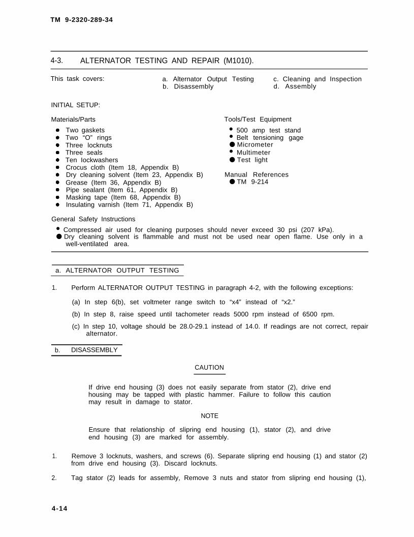
TM 9-2320-289-34
4-3. ALTERNATOR TESTING AND REPAIR (M1010).
This task covers: a. Alternator Output Testing c. Cleaning and Inspectionb. Disassembly d. Assembly
INITIAL SETUP:
Materials/Parts Tools/Test Equipment
Two gaskets • 500 amp test standTwo “O” rings • Belt tensioning gageThree locknuts ● MicrometerThree seals • MultimeterTen Iockwashers ● Test lightCrocus cloth (Item 18, Appendix B)Dry cleaning solvent (Item 23, Appendix B) Manual ReferencesGrease (Item 36, Appendix B) ● TM 9-214Pipe sealant (Item 61, Appendix B)Masking tape (Item 68, Appendix B)Insulating varnish (Item 71, Appendix B)
General Safety Instructions
• Compressed air used for cleaning purposes should never exceed 30 psi (207 kPa).● Dry cleaning solvent is flammable and must not be used near open flame. Use only in a
well-ventilated area.
a. ALTERNATOR OUTPUT TESTING
1. Perform ALTERNATOR OUTPUT TESTING in paragraph 4-2, with the following exceptions:
(a) In step 6(b), set voltmeter range switch to “x4” instead of “x2.”
(b) In step 8, raise speed until tachometer reads 5000 rpm instead of 6500 rpm.
(c) In step 10, voltage should be 28.0-29.1 instead of 14.0. If readings are not correct, repairalternator.
b. DISASSEMBLY
CAUTION
If drive end housing (3) does not easily separate from stator (2), drive endhousing may be tapped with plastic hammer. Failure to follow this cautionmay result in damage to stator.
NOTE
Ensure that relationship of slipring end housing (1), stator (2), and driveend housing (3) are marked for assembly.
1. Remove 3 locknuts, washers, and screws (6). Separate slipring end housing (1) and stator (2)from drive end housing (3). Discard locknuts.
2. Tag stator (2) leads for assembly, Remove 3 nuts and stator from slipring end housing (1),
4-14

TM 9-2320-289-34
4-3. ALTERNATOR TESTING AND REPAIR (M1010) (Con’t).
3. Remove 4 screws (14), Iockwashers (13), washers (12), brush cover (11), and brush holdergasket (15), Discard Iockwashers and gasket.
4. Remove brush holder (9). Remove 2 brushes (10) and “O“ ring (16) from brush holder.Discard “O” ring.
NOTE
Perform step 5 only if brush holder adapter (17) or connector aredamaged. Leads connected to brush holder adapter will have to be cutfrom locking terminals to remove brush holder adapter.
5. Remove 2 screws (8) and pull out brush holder adapter (17). Tag and disconnect 2 leads frombrush holder adapter, and remove brush holder adapter.
6.. Remove bushing (7) if damaged.
TA50786
4-15

TM 9-2320-289-34
4-3. ALTERNATOR TESTING AND REPAIR (M1010) (Con’t).
7 . Check resistance between output terminal screw (5) on positive rectifier (28) and slipring endhousing (1), If resistance is not infinite, replace upper housing bushing (18) and outputterminal bushing (19) in step 10. Repeat for negative rectifier (20).
8. Check resistance between outputte rm ina l sc rew (5 ) on pos i t i verectifier (28) and loop from each lead(22), Reverse multimeter probes. Ifresistance does not change, replacepositive rectifier in step 10. Repeatfor negative rectifier (20).
NOTE
Ensure that leads and outputterminal screws (5) are tagged forassembly.
9. Remove 3 screws (21) anddisconnect 2 leads from positiverectifier (28) and 1 lead fromnegative rectifier (20). Remove 2nuts (4) and output terminal screws(5) . Remove 2 screws (23),Iockwashers (24), guard washers(25), and insulation washers (26).Discard Iockwashers. Clean pipesealant from screw (23) threads.
TA50787
4-16

TM 9-2320-289-34
4-3. ALTERNATOR TESTING AND REPAIR (M1010) (Con’t).
10.
11,
NOTE
If 1 rectifier was determined to be good in step 8, but other rectifier had tobe replaced, terminal loops at each lead (22) will have to be cut toseparate positive rectifier (28) from negative rectifier (20). Ensure thatleads are tagged for assembly if this is done,
Remove positive rectifier (28) and negative rectifier (20) from slipring end housing (1).Remove 2 upper housing bushings (18), output terminal bushings (19), and lower housingbushings (27) from slipring end housing,
Tag connec to r (34 ) l eads anddisconnect from AC “terminal studs(45) and regulator holder (44).
CAUTION
DO NOT pry on regulator (31) toremove. Fai lure to fol low thiscaution may result in damage toregulator.
12. Remove 4 screws (29), Iockwashers(30), and regulator (31 ). Removeand discard gasket (35). DiscardIockwashers.
CAUTION
Before changing p o s i t i o n o fadjustment screw (32), ensurethat “HI” position hole in regulator(31) is clear of obstructions.Failure to follow this caution mayresult in damage to regulator.
13.
14.
15.
16.
Ensure that adjustment screw (32) isin “HI” position if regulator (31) willnot be replaced.
Remove 3 nuts (38), washers (37),and AC terminal studs (45).
NOTE
Perform step 15 only if brush holder adapter was removed.
Pull connector (34) lead through access hole and grommet in slipring end housing (1).Remove regulator holder (36). Remove 2 screws (33) and connector.
Remove 4 screws (44), cover plate (43), and “ O“ ring (42) from slipring end housing (1).Remove inner seal (39). Insert punch in pilot hole on cover plate side of slipring end housing.Drive out slipring bearing (40) and outer seal (41). Discard seals and “O“ ring.
TA50788
4-17

TM 9-2320-289-34
4-3. ALTERNATOR TESTING AND REPAIR (M1010) (Con’t).
17.
18.
Mark
CAUTION
Sliprings (55) should not contact any hard surface while pressing rotor(54) from drive end housing (3). Failure to follow this caution may result indamage to rotor,
relationship of woodruff key (50)to fan (49) for installation. Removenut (51), and press rotor (54) andwoodruff key out of drive end housing(3). Remove fan and fan spacer (52).
Remove 4 screws (53). Press bearingretainer (46), seal (47), and driveend bearing (48) from drive endhousing (3). Discard seal,
c. CLEANING AND INSPECTION
WARNING
● Dry cleaning solvent P-D-680 is toxic and flammable. Always wearprotective goggles and gloves and use only in a well-ventilated area.Avoid contact with skin, eyes, and clothes and DO NOT breathe vapors.DO NOT use near open flame or excessive heat. The solvent’s flashpoint Is 100°F-138°F (38°C-59°C). If you become dizzy while usingcleaning solvent, immediately get fresh air and medical help, If solventcontacts eyes, immediately wash your eyes with water and get medicalaid.
• Compressed air used for cleaning purposes should never exceed 30 psi(207 kPa). Use only effective chip guarding and personnel protectiveequipment (goggles/shield, gloves, etc.). Failure to follow this warningmay result in serious injury to personnel.
1. Clean all components with dry cleaning solvent and dry with compressed air,
TA50789
4-18

TM 9-2320-289-34
4-3. ALTERNATOR TESTING AND REPAIR (M1010) (Con’t).
2.
3.
4.
5.
6.
7.
8.
Inspect all components for damage or corrosion. Replace cracked components. Repair orreplace any component that is nicked or scratched, Remove any corrosion with crocus cloth.
Inspect stator for burned, charred, or broken wires. Replace stator if wires are burned,charred, or broken.
Check resistance between each stator lead and stator frame. If there is not infinite resistance,replace stator.
Inspect connector terminals to see if any are recessed into connector. Replace connector ifany terminals are recessed.
Inspect bearings in accordance with TM 9-214.
Measure slipring (55) diameter, If diameter is less than 0.767 in. (19.48 mm) replace rotor.
Measure slipringwina bearing inner race diameter at several points and compare readings.Maximum difference in diameter (out-of-round) should be 0.002 in. (0.051 mm). If diameter isless than 0.871 in. (22. 12 mm), or if bearing race is out-of-round, replace slipring bearing.
d. ASSEMBLY]
into drive end housing. Install 4 screws (53).
CAUTION
Sliprings (55) should not contact any hard surface while pressing rotor(54) into drive end housing (3). Failure to follow this caution may result indamage to rotor.
2. Press rotor (54) into drive end housing (3) and install woodruff key (50). Install fan spacer (52)on rotor shaft. Aline fan (49) to woodruff key and install with nut (51).
4-19

TM 9-2320-289-34
4-3. ALTERNATOR TESTING AND REPAIR (M1010) (Con’t).
3 . Install new outer seal (41) in slipringend housing (1) with flat side facingpilot holes. Press slipring bearing (40)into slipring end housing. Install newinner seal (39) flush with slipring endhousing. Install new “O” ring (42) andcover plate (43) with 4 screws (44),
NOTE
Perform step 4 only if connector(34) was removed.
4 . Install connector (34) on regulatorholder (36) with 2 screws (33). Installregulator with connector leadsthrough slipring end housing (1),Install connector lead throughgrommet and brush holder adapterhole.
5 . Install 3 AC terminal studs (45) with 3washers (37) and nuts (38).
CAUTION
Before changing pos i t i on o fadjustment screw (32), ensurethat “HI*’ position hole in regulator(31) is c lear of obstruct ions.Failure to follow this caution mayresult in damage to regulator.
6 . Ensure that adjustment screw (32) is in “HI” position if regulator (31) was replaced.
7 . Install new gasket (35) on regulator holder (36). Install regulator (31) with 4 new Iockwashers(30) and screws (29).
8 . Connect connector (34) leads to AC terminal studs (45) and regulator holder (36).
9 . Apply pipe sealant to screw (23) threads. Install 2 insulation washers (26), guard washers(25), new Iockwashers (24), screws (23), and output terminal screws (5) on positive rectifier(28) and negative rectifier (20).
TA50790
4-20

TM 9-2320-289-34
4-3. ALTERNATOR TESTING AND REPAIR (M1010) (Con’t).
NOTE
If either rectifier was replaced,leads (22) will have to be splicedtogether with terminal loopsbefore installing positive rectifier(28) and negative rectifier (20).
10.
11.
Install 2 lower housing bushings (27)on screws (23). Install output terminalbushings (19) and upper housingbushings (18) on output terminalscrews (5). Install rectifier assemblyin slipring end housing (1) and install2 nuts (4) on output terminal screws,
Connect 2 leads to positive rectifier(28) and 1 lead to negative rectifier(20), and install 3 screws (21).Connect rectifier leads (22) to ACterminal studs (45).
TA50791
4-21

TM 9-2320-289-34
4-3. ALTERNATOR TESTING AND REPAIR (M1010) (Con’t).
12.
13.
14.
15.
Install bushing (7) if removed.
NOTE
Perform step 13 only if brush holder adapter (17)that locking terminals are installed on leads beforeadapter.
Connect 2 leads to brush holderadapter (17). Ensure that leads lockon brush holder adapter. Install brushholder adapter with 2 screws (8).
Install new “O“ ring (16) and 2brushes (10) in brush holder (9).Press brush holder onto brush holderadapter (17).
Install new brush holder gasket (15)and brush cover (11), with 4 washers(12), new Iockwashers (13), andscrews (14).
was removed. Ensureinstalling brush holder
NOTE
Perform step 16 only if stator (2) was not replaced.
16. Mask machined edges of stator (2) with tape, Paint stator with insulating varnish. Wipe excessinsulating varnish from stator inside diameter. Remove tape,
17. Install stator (2) on slipring end housing (1) and aline marks made during disassembly. Installstator leads with 3 nuts.
TA50792
4-22

TM 9-2320-289-34
4-3. ALTERNATOR TESTING AND REPAIR (M1010) (Con’t).
18. Assemble drive end housing (3),stator (2), and slipring end housing( I), Install 3 screws (6), washers,and new locknuts.
T A 5 0 7 9 3
4 - 2 3

TM 9-2320-289-34
4-4. CURRENT/VOLTAGE REGULATOR AND RELAY REPLACEMENT (M1010).
This task covers: a. Removal b. Installation
INITIAL SETUP:
Equipment condition Materials/Parts
. Both battery negative cables disconnected, Ž Lockwashers (as needed)(See TM 9-2320-289-20) ● RTV sealant (Item 57, Appendix B)
1. Remove 2 mounting screws (10) and current/voltage regulator cover (11) from inside of leftfender.
NOTE
Ensure that leads and current/voltage regulator filter assembly (5) aretagged for installation,
2. Remove 5 nuts (9) and Iockwashers, and disconnect leads and current/voltage regulator filterassembly (5). Discard Iockwashers.
3. Remove 3 bolts (8) and mounting bracket (7).
4. Remove nuts and Iockwashers, and disconnect leads from current/voltage regulator relay (2).Remove 2 retaining screws (3) and current/voltage regulator relay from mounting bracket (7),Discard Iockwashers.
5. Loosen 3 lower retaining screws. Remove 3 upper retaining screws (4) and nuts, andcurrent/voltage regulator (6) from mounting bracket (7).
b. INSTALLATION
1.
2.
3.
CAUTION
DO NOT continue rotating adjustment screw (12) after resistance is felt.Adjustment screw adjustment should never exceed 3/4 turn. Failure tofol low this caut ion may damage adjustment screw and requirereplacement of current/voltage regulator (6),
Remove tape cover ing adjustment screw (12). Gent ly rotate adjustment screwcounterclockwise until slight resistance is felt, If no further testing is required, apply RTVsealant to completely cover adjustment screw,
Position current/voltage regulator (6) on 3 lower retaining screws and mounting bracket (7),and hold in place by tightening screws. Install 3 upper retaining screws (4) on current/voltageregulator with nuts.
NOTE
Ensure that 1 bolt (8) is installed through
Install mounting bracket (7) with 3 bolts (8),
washer solvent container (1),
4-24

TM 9-2320-289-34
4-4 . CURRENT/VOLTAGE REGULATOR AND RELAY REPLACEMENT (M1010)(Con’t).
4. Install current/voltage regulator relay (2) on mounting bracket (7) with 2 retaining screws (3).Connect leads to current/voltage regulator relay, and install new Iockwashers and nuts.
5. Install current/voltage regulator filter assembly (5) and leads with 5 new Iockwashers and nuts(9) .
6. Install current/voltage regulator cover (11) with 2 mounting screws (10).
FOLLOW-ON TASKS:
● Connect both battery negative cables. (See TM 9-2320-289-20)
TA50794
4-25

TM 9-2320-289-34
4-5. STARTER TESTING AND REPAIR.
This task covers: a. Testing c. Cleaning and Inspectionb. Disassembly d. Assembly
INITIAL SETUP:
MaterialslParts Too/s/Test Equipment
●
●
●
●
●
●
One fiber washer • 500 amp test standTwo electrical parts kits • GrowlerSix Iockwashers • Hacksaw bladeDry cleaning solvent (Item 23, Appendix B) ● MultimeterGrease (Item 36, Appendix B) • Test lightSealing compound (Item 60, Appendix B)
General Safety Instructions
• Compressed air used for cleaning purposes should never exceed 30 psi (207 kPa).• Dry cleaning solvent is flammable and must not be used near open flame. Use only in a
well-ventilated area.
1.
2.
3.
4 .
5.
6.
7.
8.
Turn pinion on screw shaft to check for freedom of operation, Check armature for freedom ofrotation by prying on pinion with screwdriver.
If pinion does not operate freely, or if armature does not rotate freely, repair starter. If pinionand armature are good, test starter.
Mount starter on 500 amp test stand as shown. Supply starter with 24 volts, andrecord amperage and starter rpm.
Readings should be 40-80 amps and 8000-12500 rpm, If readings are not correct, repairstarter using guidelines in steps 5-9.
If there is low rpm and high amperage, check for:
(a) Tight, dirty, or worn bearings
(b) Bent or shorted armature
(c) Grounded armature or fields
If there is high amperage and starter does not operate, check for direct ground in terminal orfields.
If there is no amperage and starter does not operate, check for:
(a) Open field circuit; check connections through field with test light.
(b) Open armature coils; inspect commutator for badly burned bars.
(c) Broken brush springs, worn brushes, high insulation between commutator bars, or otherconditions that would prevent good contact between brushes and commutator.
If there is low rpm and low amperage, check for poor connections, defective leads, or dirtycommutator.
4-26

TM 9-2320-289-34
4-5. STARTER TESTING AND REPAIR (Con’t).
9. If there is high rpm and high amperage, check for:
(a) Shorted fields; replace field coil assembly.
(b) Shorted armature.
TA50796
4-27

TM 9-2320-289-34
4-5. STARTER TESTING AND REPAIR (Con’t).
b. DISASSEMBLY
1. Remove screw (8) from field coilconnector (7). Remove 2 screws (9)and Iockwashers. Rotate solenoid (2)90 degrees, and remove solenoidand plunger spring (10). DiscardIockwashers.
2 . Remove stud (4), bol t (5), andcommutator end frame (6). Removefield housing (3) assembly from drivegear housing (1).
3 . Remove snapring (15) and shift levershaft (14), Remove shift lever (16)and plunger (11 ) assembly from driveassembly (21), Remove roll pin (13),plunger, and boot (12) from shiftlever.
TA50796
4 - 2 8

TM 9-2320-289-34
4-5. STARTER TESTING AND REPAIR (Con’t).
4. Remove 3 screws (26), washers (25), and center bearing (19) and armature (17) assemblyfrom drive gear housing (1). Remove and discard fiber washer (27).
5. Remove thrust washer (23). Slide a socket or piece of pipe over end of armature (17) shaftagainst collar (22). Drive collar off stopring (24), and remove stopring and collar.
6. Separate armature (17), center bearing (19), washer (20), and drive assembly (21). Removebushing (18) if damaged.
TA50797
4-29

TM 9-2320-289-34
4-5. STARTER TESTING AND REPAIR (Con’t).
7 .
8 .
9 .
Check continuity between field housing (3) and brushes (34) at grounded brush holders (35).Check continuity between field coil connector (7) and brushes at insulated brush holders (31).
If there is no continuity in step 7, check connections at brushes (34) and brush holders (31 and35). Replace any damaged components. If connections are good, and no components appeardamaged, replace field coil assembly (38).
Check for continuity between brushes (34) at grounded brush holders (35) and brushes atinsulated brush holders (31). If there is continuity, replace field coil assembly (38).
NOTE
Ensure that all leads are tagged for installation,
10. Remove brush support pin (28). Separate brush spring (30), grounded brush holder (35), andinsulated brush holder (31 ) from brush support (29).
11. if removing field coil assembly (38) or brushes (34), remove 2 screws (33) at insulated brushholders (31) and disconnect field coil assembly leads (32), Remove screw and disconnectfield coil assembly lead from field coil connector (7). Remove field coil connector andgrommet if damaged.
TA50798
4-30

TM 9-2320-289-34
4-5. STARTER TESTING AND REPAIR (Con’t).
NOTE
Ensure that position of field coil assembly (38) is noted for assembly.
12. Remove 8 pole shoe screws (36) and 4 pole shoes (37). Remove field coil assembly (38) fromfield housing (3). Remove alinement pin (39) if damaged.
c . CLEANING AND INSPECTION I
WARNING
Ž Dry cleaning solvent P-D-680 is toxic and flammable. Always wearprotective goggles and gloves and use only in a well-ventilated area.Avoid contact with skin, eyes, and clothes and DO NOT breathe vapors.DO NOT use near open flame or excessive heat. The solvent’s flashpoint is 100°F-138°F (38°C-59°C). If you become dizzy while usingcleaning solvent, immediately get fresh air and medical help. If solventcontacts eyes, immediately wash your eyes with water and get medicalaid.
• Compressed air used for cleaning purposes should never exceed 30 psi(207 kPa). Use only effective chip guarding and personnel protectiveequipment (goggles/shield, gloves, etc.). Failure to follow this warningmay result in serious injury to personnel.
TA50799
4-31

TM 9-2320-289-34
4-5. STARTER TESTING AND REPAIR (Con’t).
CAUTION
Dry cleaning solvent should not contact drive assembly, armature,brushes, field coil. or nonmetallic parts. Failure to follow this caution mayresult in damage to these components.
1 . Clean drive assembly, armature, brushes, field coils, and all nonmetallic components withclean, dry brush or cloth. Remove any loose particles with compressed air.
2 . Clean all remaining components with cloth dampened with dry cleaning solvent. Dry withcompressed air.
3. Inspect all components for discoloration and damage. Replace any discolored or damagedcomponent.
NOTE
Short circuit will pull hacksaw blade (40) against armature (17) and makehacksaw blade vibrate.
4. Install armature (17) on growler (41).Hold hacksaw blade (40) just abovearmature core while rotatingarmature. if hacksaw blade vibrates,clean between armature bars and tryagain. If hacksaw blade still vibrates,replace armature.
d. ASSEMBLY
1. Install alinement pin (39) if removed. install field coil assembly (38) in field housing (3). Install4 pole shoes (37) on field coil assembly with 8 pole shoe screws (36).
TA50800
4-32

TM 9-2320-289-34
4-5. STARTER TESTING AND REPAIR (Con’t).
TA50801
4-33

TM 9-2320-289-34
4-5. STARTER TESTING AND REPAIR (Con’t).
NOTE
If field coil assembly was removed, ensure that 2 field coil assembly leads(32) are installed with brushes (34) at insulated brush holders (31).
2. Install grommet and field coil connector (7) in field housing (3) if removed. Connect field coilassembly lead (32) to field coil connector with screw (33), Connect remaining field coilassembly leads at insulated brush holders (31) and install brushes (34) with remaining screws,
3. Assemble insulated brush holder (31) and grounded brush holder (35) on brush support (29)with brush spring (30), Install brush support pin (28).
4. install bushing (18) in center bearing (19) if removed. Lubricate shaft end of armature (17)with grease. Assemble drive assembly (21), washer (20), center bearing, and armature.
5. install collar (22) on armature (17) shaft, with cupped end facing end of shaft, Install stopring(24) in armature shaft groove, Install thrust washer (23). Squeeze collar and thrust washertogether until collar is forced over retainer,
TA50802
6. Install new fiber washer (27) on armature (17). install center bearing (19) and armatureassembly on drive gear housing (1) with 3 washers (25), and screws (26),
4-34

TM 9-2320-289-34
4-5. STARTER TESTING AND REPAIR (Con’t).
7. Install boot (12) and plunger (11) on shift lever (16) with roll pin (13). Install shift lever andplunger assembly on drive assembly (21). Install shift lever shaft (14) on shift lever withsnapring (15).
TA50803
4-35

T M 9 - 2 3 2 0 - 2 8 9 - 3 4
4-5. STARTER TESTING AND REPAIR (Con’t).
CAUTION
Ensure that field housing (3) assembly is carefully positioned on drive gearhousing (1). Failure to follow this caution may result in damage tobrushes.
8 . Position field housing (3) assembly ondrive gear housing (1) ensuring thatalinement pin engages drive gearhousing hole. install commutator endframe (6) on field housing with bolt(5) and stud (4).
9 . Apply sealing compound to solenoid(2) flange where it contacts fieldhousing (3). install plunger spring(10) in solenoid. Rotate solenoid 90degrees and install on drive gearhousing (1) with 2 new lockwashersand screws (9).
10. Carefully insulate field coil connector(7) f rom solenoid (2) terminal .Connect one 24 volt battery leadfrom 500 amp test stand to solenoidterminal and other battery lead tostarter frame.
TA50804
4 - 3 6

TM 9-2320-289-34
4-5. STARTER TESTING AND REPAIR (Con’t).
11.
12,
13.
Connect jumper lead momentarilyfrom solenoid (2) terminal to starterframe. This will move pinion (42) intocranking position until battery leadsare disconnected.
Check clearance between pinion (42)and collar (22). If clearance is not0.010-0.140 in. (0.25-3.56 mm),disconnect test stand battery leads,disassemble starter, and check forincorrect installation. Replace anyworn components and retest,
Disconnect test stand battery leads.Remove insulation between field coilconnector (7) and solenoid (2)terminal, Install screw (8) on field coilconnector,
TA50805
4-37

TM 9-2320-289-34
4-6. INSTRUMENT PANEL WIRING HARNESS AND EXTENSION REPLACEMENT.
This task covers: a. Removal b. Installation
INITIAL SETUP:
Equipment Condition Materials /Parts
• Instrument cluster removed, ● Grease (Item 36, Appendix B)(See TM 9-2320-289-20) ● Antiseize tape (Item 65, Appendix B)
• Voltmeter relay, generator 2 relay, and starterrelay removed, (See TM 9-2320-289-20) Manual References
• Transfer case bezel, plate, boot, and control ● TM 9-2320-289-20lever housing removed.(See TM 9-2320-289-20)
• Instrument panel padding removed.(See TM 9-2320-289-20)
a. REMOVAL
NOTE
• If removing all except M1010 instrument panel wiring harness, performsteps 1 through 7, 9 through 12, and 14.
• I f removing M1010 instrument panel wir ing harness, performsteps 1-14.
• If removing instrument panel extension wiring harness, perform steps 13and 15.
• Voltmeter lamp connector (8), “WATER-IN-FUEL” light connector (11 ),“WAIT” light connector (12), and instrument cluster connector (13)were disconnected when instrument cluster was removed.
• Ensure that all leads and connectors are tagged for installation.
1. At underside of steering column (1),disconnect wiper/washer switchconnector (4) from wiper/washerswitch (3). Unplug wiper/washerswitch from bracket (2).
TA50806
4 - 3 8 Change 2

TM 9-2320-289-34
4-6. INSTRUMENT PANEL WIRING HARNESS AND EXTENSION REPLACEMENT(Con’t).
2 . Disconnect headlight switch connector (14), 2 blackout Iight switch connectors (15), and hornrelay (20). Remove horn rectifier (21) if damaged.
3 . Remove screw (16), ground lead (17), and wiring harness terminal (18).
TA50807
4-39

TM 9-2320-289-34
4-6. INSTRUMENT PANEL WIRING HARNESS AND EXTENSION REPLACEMENT(Con’t).
4. At lower part of steering column (1), disconnect directional signal connector (27), ignitionswitch connector (28), back-up light switch connector (26), and dimmer switch connector(29) ,
5. Inside engine compartment,disconnect wiring harnesses fromrear of fuse box (22).
6 . Remove turn signal flasher from fusebox. Remove 2 screws (30) and bolt(31 ), and pull out fuse box (22). Wipegrease from exterior of fuse box ifinstrument panel wiring harness willnot be replaced.
TA50808
4-40

TM 9-2320-289-34
4-6. INSTRUMENT PANEL WIRING HARNESS AND EXTENSION REPLACEMENT(Con’t).
7. Disconnect heater lamp connector (7), heater connector (10), and glow plug wiring harnessconnector (23).
8 . Disconnect spotlight switch connector (19), 2 floodlight switch connectors (9), and GPFUswitch connector (25). Disconnect open door buzzer wiring harness connector from below“WATER-IN-FUEL” connector (11).
TA50809
4-41

TM 9-2320-289-34
4-6. INSTRUMENT PANEL WIRING HARNESS AND EXTENSION REPLACEMENT(Con’t).
9 . Disconnect transfer case connector (33) from 4-wheel drive switch (34), Disconnect courtesylight connector (32),
TA50810
4-42

TM 9-2320-289-34
4-6. INSTRUMENT PANEL WIRING HARNESS AND EXTENSION REPLACEMENT(Con’t).
10. On underside of transfer case controllever reinforcement (36), removetape (35) and pull transfer caseconnector (33) lead up through floor.
1 1 . Disconnect leads from acceleratorbracket and seatbelt retractorconnector.
12. Remove 2 nuts (39), washers (38),and support (37). Lower steeringcolumn (1).
TA50811
4-43

TM 9-2320-289-34
4-6. INSTRUMENT PANEL WIRING HARNESS AND EXTENSION REPLACEMENT(Con’t).
1 3 . Disconnect extension wiring harness connector (43) from extension wiring harness (40).
14. Remove insulator (5), Unsnap clips along dash (6) and remove instrument panel wiringharness. Remove blackout light relay (24) if damaged. If replacing instrument panel wiringharness, remove hazard flasher and all fuses, and save for installation.
15. Remove 5 screws (45) from clamps (44), Unsnap extension wiring harness (40) clips fromframe (41). Disconnect ambulance body accessory connectors (42). Pull extension wiringharness through grommet (46) into engine compartment to remove. Remove grommet ifdamaged.
b. INSTALLATION
NOTE
• If installing instrument panel extension wiring harness (40), performsteps 1 and 4.
• If Installing all except Ml1010 instrument panal wiring harness, performsteps 2, 3, 5 through 8, and 10 through 16.
Ž If installing M1010 instrument panel wiring harness, performsteps 2-16.
TA50812
4-44

TM 9-2320-289-34
4-6. INSTRUMENT PANEL WIRING HARNESS AND EXTENSION REPLACEMENT(Con’t).
TA50813

TM 9-2320-289-34
4-6. INSTRUMENT PANEL WIRING HARNESS AND EXTENSION REPLACEMENT(Con’t).
NOTE
Ž Voltmeter lamp connector (8), “WATER-IN-FUEL” light connector (11),“WAIT” light connector (12), and instrument cluster connector (13)will be connected when instrument cluster is installed.
• Ensure that all connectors are seated and locked in place as they areinstalled.
1. Install grommet (46) if removed. Push extension wiring harness (40) through grommet.Connect ambulance body accessory connectors (42). Snap extension wiring harness clipsalong frame (41), Install clamps (44) along frame with 5 screws (45).
2. If instrument panel wiring harness was replaced, install hazard flasher and all fuses. (SeeTM 9-2320-289-20)
3. Install blackout light relay (24) if removed. Snap instrument panel wiring harness clips alongdash (6). Install insulator (5).
TA50814
4-46

TM 9-2320-289-34
4-6. INSTRUMENT PANEL WIRING HARNESS AND EXTENSION REPLACEMENT(Con’t).
4 . Connect extension wiring harness connector (43) to extension wiring harness (40).
TA50815
4 - 4 7

TM 9-2320-289-34
4-6. INSTRUMENT PANEL WIRING HARNESS AND EXTENSION REPLACEMENT(Con’t).
5. Raise steering column (1), and installsupport (37) with 2 washers (38) andnuts (39).
6. Connect leads to accelerator bracketand seatbelt retractor connector.
7. Push transfer case connector (33)lead through floor and connect to4-wheel drive switch (34), Installtransfer case connector lead totransfer case control leverreinforcement (36) with tape (35).
8. Connect courtesy light connector(32) .
TA50816
4-48

TM 9-2320-289-34
4-6. INSTRUMENT PANEL WIRING HARNESS AND EXTENSION REPLACEMENT(Con’t).
TA50817
4 - 4 9

TM 9-2320-289-34
4-6. INSTRUMENT PANEL WIRING HARNESS AND EXTENSION REPLACEMENT(Con’t).
9. Connect open door buzzer wiring harness connector below “WATER-IN-FUEL” light connector(11). Connect spotlight switch connector (19), 2 floodlight switch connectors (9), and GPFUswitch connector (25).
10. Connect heater lamp connector (7), heater connector (10), and glow plug wiring harnessconnector (23).
T A 5 0 8 1 8
4-50

TM 9-2320-289-34
4-6. INSTRUMENT PANEL WIRING HARNESS AND EXTENSION REPLACEMENT(con’t).
11. Apply grease to sealing surfaces offuse box (22). Install fuse box withbolt (31) and 2 screws (30). Installturn signal flasher.
12. Inside engine compartment, connectwiring harnesses to rear of fuse box(22) .
13. At lower part of steering column (1), connect directional signal connector (27), ignition switchconnector (28), back-up light switch connector (26), and dimmer switch connector (29).
14. Install wiring harness terminal (18) and ground lead (17) with screw (16).
15. Install horn rectifier (21) if removed. Connect headlight switch connector (14), 2 blackout lightswitch connectors (15), and horn relay (20).
TA50819
4-51

TM 9-2320-289-34
4-6. INSTRUMENT PANEL WIRING HARNESS AND EXTENSION REPLACEMENT(Con't).
16. At underside of steering column (1),connect wiper/washer switchconnector (4) to wiper/washer switch(3). Plug wiper/washer switch ontobracket (2).
FOLLOW-ON TASKS:
● Ins ta l l Instrument panel padding, (See TM 9-2320-289-20)● Install transfer case bezel, plate, boot, and control lever housing. (See TM 9-2320-289-20)● Install voltmeter relay, generator 2 relay, and starter relay. (See TM 9-2320-289-20)● Install instrument cluster. (See TM 9-2320-289-20)
TA50820
4 - 5 2 Change 2

TM 9-2320-289-34
4-7. FRONT WIRING HARNESS REPLACEMENT.
This task covers: a. Removal b. Installation
INITIAL SETUP:
Equipment Condition Materials/Parts
●
●
●
●
Front battery~ removed. ● Two Iockwashers(See TM 9-2320-289-20) ● Three starwashersFront battery box removed (if truck is ● Tie-down straps (as needed)equipped with winterization kits). (Item 63, Appendix B)(See TM 9-2320-289-20)Radiator grille removed.(See TM 9-2320-289-20)Front blackout marker lights removed.(See TM 9-2320-289-20)
a . R E M O V A L
1. Remove bolt and disconnect fuse box connector (1) from rear of fuse box. Separate f rentwiring harness connectors from fuse box connector assembly.
2. Open clips retaining front wiring harness (2) to left fenderwell (4).
3. Cut and discard tie-down straps retaining front wiring harness (2) to windshield washer hose.Loosen screws securing washer solvent container (3) and pull front wiring harness free.
TA50821
4-53

TM 9-2320-289-34
4-7. FRONT WIRING HARNESS REPLACEMENT (Con’t).
4. Remove bolt (7), Iockwasher (10), ground lead (8), and starwasher (9). Disconnect headlightconnector (11), parking light connector (12), and marker light connector (13). DiscardIockwasher and starwasher,
5. Disconnect blackout drive light connector (5) and horn capacitor connector (6).
TA50822
4-54

TM 9-2320-289-34
4-7. FRONT WIRING HARNESS REPLACEMENT (Con’t).
6.
7.
8.
9.
Disconnect combination valveconnector (16) from brake indicatorlight bracket (14).
Disconnect brake indicator light wire(17) from combination valve (18) andbrake indicator light bracket (14) ifdamaged. Remove screw (15) andbrake indicator l ight bracket i fdamaged.
Remove 2 bolts (23), Iockwasher(22), battery lead (21), ground lead(20), and 2 starwashers (19). DiscardIockwasher and starwashers.
Disconnect headlight connector (28),parking light connector (25), andmarker light connector (24) .Disconnect low coolant sensorconnector (26) from low coolantsensor (27).
TA60823
4 - 5 5

TM 9-2320-289-34
4-7. FRONT WIRING HARNESS REPLACEMENT (Con’t).
CAUTION
Care should be taken during removal of front wiring harness (2) to preventsnagging it. Failure to follow this caution may result in damage to frontwiring harness.
NOTE
Ensure that position of front wiring harness (2) is noted for installation.
10. Open clips retaining front wiring harness (2) to radiator support. Remove front wiring harness.
b. INSTALLATION
NOTE
Ensure that all connectors are seated and locked in place as they areinstalled.
1 . Route front wiring harness (2) through radiator support into engine compartment. Install frontwiring harness into clips along radiator support.
2 . Connect low coolant sensor connector (26) to low coolant sensor (27). Connect headlightconnector (28), parking light connector (25), and marker light connector (24).
TA50824
4-56

TM 9-2320-289-34
4-7. FRONT WIRING HARNESS REPLACEMENT (Con’t).
3 . Install ground lead (20) and battery lead (21 ) with 2 new starwashers (19), new Iockwasher(22), and 2 bolts (23).
4. Install brake indicator light bracket(14) with screw (15) if removed.Connect brake indicator light wire(17) to combination valve (18) andbrake indicator l ight bracket i fremoved.
5. Connect combination valve connector(16) to brake indicator light bracket(14).
TA60826
4-67

TM 9-2320-289-34
4-7. FRONT WIRING HARNESS REPLACEMENT (Con’t).
6. Connect blackout drive light connector (5) and horn capacitor connector (6).
7. Connect headlight connector (11 ), parking light connector (1 2), and marker light connector(13). Install ground lead (8) with new starwasher (9), new Iockwasher (10), and bolt (7).
8. Route front wiring harness under washer solvent container (3) and tighten screws securingwasher solvent container.
9. Install front wiring harness (2) into clips along left fenderwell (4). Install front wiring harnessonto windshield washer hose with new tie-down straps.
10. Assemble front wiring harness (2) to fuse box connector. Connect fuse box connector (1) torear of fuse box and install bolt.
TA50826
4-58

TM 9-2320-289-34
4-7. FRONT WIRING HARNESS REPLACEMENT (Con’t).
FOLLOW-ON TASKS:
Install front blackout marker lights. (See TM 9-2320-289-20)Install radiator grille. (See TM 9-2320-289-20)Install front battery box if removed. (See TM 9-2320-289-20)Install front battery. (See TM 9-2320-289-20)Check operation of front lights.
4-59

TM 9-2320-289-34
4-8. BODY WIRING HARNESS REPLACEMENT.
This task covers: a . Remova l b. Installation
INITIAL SETUP:
Equipment Condition Materiels/Parts
● Both battery negative cables disconnected. • One starwasher(See TM 9-2320-289-20)
a . R E M O V A L
NOTE
● If removing body wiring harness(1) f rom al l except M1009,perform steps 1-3, 5, and 6,
• If removing body wiring harness(1) from Ml 009, perform steps1, 2, 4, 5, and 7 through 10.
• Ensure that all leads are taggedfor Installation.
1 . Remove bolt and disconnect bodywiring harness (1) at rear of fuse box(3). Disconnect red lead at fuse box.Depress sides of terminal “30” onfuse box, and disconnect pinksending unit lead by pulling leadtoward front of connector.
2 . Open clip (8) retaining body wiringharness (1) to engine bulkhead (2).Unsnap body wiring harness fromengine bulkhead,
3 . Remove nut (5), open clip (6), andpull body wiring harness (1) free. Pullspeedometer cable free if retained byclip. Remove bolt (4) and retainerplate (7) from inside cab if damaged.
4 . Open adjustable retainer (9). Remove 5 bolts (10), 3 small clips (12), axle vent hose clip (13),and large clip (11) from frame (14). Remove 2 nuts and ground wire, from right and leftblackout markers.
TA50827
4 - 6 0

TM 9-2320-289-34
4-8. BODY WIRING HARNESS REPLACEMENT (Con’t).
5. Remove screw (19) and starwasher (18), and disconnect ground lead (15) from rear frame(14). Disconnect fuel tank sending unit lead (16). Discard starwasher.
6. Disconnect body wiring harness (1) from taillight wiring harness. Unsnap 9 clips (17) fromalong frame (14) and remove body wiring harness.
TA50828
4-81

TM 9-2320-289-34
4-8. BODY WIRING HARNESS REPLACEMENT (Con’t).
7. Unsnap 1 clip (17) from frame (14),Disconnect body wiring harness (1)from right and left taillight wiringharness, and trailer wiring harness,Remove 2 nuts (21) and clips (22)from frame studs (20). Unsnap clipssecur ing r ight and lef t b lackoutmarker harnesses to bumperbracket. Pull taillight wiring harnessthrough holes in frame on right andleft sides,
8. Lower body wiring harness from engine compartment. Attach a guide wire approximately 7 ft.(2. 1 m) long to bulkhead end of body wiring harness (1).
9. Remove screw (25) and clip (24) from frame (14). Unsnap 4 clips (23) from frame andremove body wiring harness (1) from frame.
10. Remove body wiring harness (1) by pulling harness from rear of truck, guiding harness throughopening in rear frame member. Remove harness from guide wire and leave guide wire in placein frame to aid in installation.
b. INSTALLATION
NOTE
● If installing body wIlrlng harness (1) for all except Ml 009, perform steps3, 4, and 6 through 8.
● If Installing body wiring harness (1) for Ml 009, perform steps 1, 2, 4, 5,7, and 8.
● Ensure that all connectors are seated and locked in place as they areinstalled.
1. Attach bulkhead end of body wiring harness (1) to guide wire at rear of vehicle. Guide wiringharness through frame and disconnect guide wire. Route wiring harness to bulkhead connectorin engine compartment,
TA50829
4-62

TM 9-2320-289-34
4-8. BODY WIRING HARNESS REPLACEMENT (Con’t).
2 . Snap 4 clips (23) with body wiring harness (1) into place along frame (14). Install clip (24) onframe with screw (25).
3 . Route taillight wiring harness through holes in frame on right and left sides. Install 2 clips (22)on frame studs (20) with 2 nuts (21). Connect body wiring harness (1) to taillight wiringharness and trailer wiring harness.
TA502830
4 - 6 3

TM 9-2320-289-34
4-8. BODY WIRING HARNESS REPLACEMENT (Con’t).
4 . Snap 9 clips (17) with body wiring harness (1) along frame (14). Connect body wiring harnessto taillight wiring harness.
5 . Connect fuel tank sending unit lead (16). Connect ground lead (15) and secure with screw(19), and new starwasher (18).
6. Install large clip (11) and 3 small clips (12) on body wiring harness (1). Install axle vent hoseclip (13) on body wiring harness and axle vent hose. Install clips on frame with 5 bolts (10).Install body wiring harness in adjustable retainer (9).
TA50831
4-64

TM 9-2320-289-34
4-8. BODY WIRING HARNESS REPLACEMENT (Con’t).
7 . Install retainer plate (7) and bolt (4)from inside cab if removed. Installbody wiring harness (1) andspeedometer cable in clip (6). Installclip on retainer plate with nut (5).
8 . Snap body wiring harness (1) toengine bulkhead (2), Install bodywiring harness in clip (8).
9 . Install pink sending unit lead frombody wiring harness into terminal“30” on fuse box, Connect red leadat fuse box. Connect body wiringharness (1) at rear of fuse box (3).
FOLLOW-ON TASKS:
● Connect both battery negative cables. (See TM 9-2320-289-20)TA50832
4 - 6 5

TM 9-2320-289-34
4-9. TAILLIGHT WIRING HARNESS REPLACEMENT (M1010 AND M1031).
This task covers: a . R e m o v a l b. Instal lat ion
INITIAL SETUP:
Equipment Condition Materials/Parts● Rear blackout marker lights removed. • One starwasher
(See TM 9-2320-289-20)
a. REMOVAL
NOTE
● Ensure that all connectors are tagged for installation.
● Perform steps 2 and 3 if removingM1031.
1. Remove connectors (3) from side marker light
taillight wiring harness (4) from
housings. Remove side marker light bulbs (2),
TA50833
4-66

TM 9-2320-289-34
4-9. TAILLIGHT WIRING HARNESS REPLACEMENT (M1010 AND M1031) (Con’t).
2. Disconnect taillight wiring harness (4) connectors from taillight connectors (5). Remove screw(8) and starwasher (7), and disconnect ground lead (6) from frame (1). Discard starwasher.
3. Disconnect taillight wiring harness (4) from body wiring harness (9). Unsnap taillight wiringharness from frame rail (10) and remove.
b. INSTALLATION
NOTE
• Perform steps 1 and 2 if installing taillight wiring harness (4) on M1031.
● Ensure that all connectors are seated and locked in place as they areinstalled.
1. Snap taillight wiring harness (4) to frame rail (10). Connect taillight wiring harness to bodywiring harness (9).
2. Connect ground lead (6) to frame (1) with new starwasher (7) and screw (8). Connect taillightwiring harness (4) connectors to taillight connectors (5).
TA50834
4 - 6 7

TM 9-2320-289-34
4-9. TAILLIGHT WIRING HARNESS REPLACEMENT (M1010 AND M1031) (Con’t).
3 . install bulbs (2). Install connectors (3) to side marker light housings.
FOLLOW-ON TASKS:
● Install rear blackout marker lights. (See TM 9-2320-289-20)• Check operation of taillights.
TA50835
4 - 8 8

TM 9-2320-289-34
4-9.1. REAR FENDER WIRING HARNESS REPLACEMENT (M1028A2).
This task covers: a. Removal b. Installation
INITIAL SETUP:
Equipment Condition
● Rear fender side marker lights removed.(See TM 9-2330-289-20).
● Taillight and lamps removed.(See TM 9-2320-289-20)
a. REMOVAL
NOTE
Rear fender wiring harness is removed from both sides in same manner.
1. Remove 14 bolts (12), 1 nut (13), and inner filler panel (11).
2. Disconnect rear fender wiring harness (8) from rear lamp wiring harness (7).
3. Remove screw (5) and disconnect ground wire (6).
4, Remove 2 nuts (1), washers (2), bolts (4), and shields (10) from inner fender (9).
Change 1 4-68.1

TM 9-2320-289-34
4-9.1. REAR FENDER WIRING HARNESS REPLACEMENT (M1028A2) (Con’t).
5. Remove 2 grommets (3), Unsnap rear fender wiring harness (8) from body and remove.
b. INSTALLATION
1 .
2 .
3 .
4 .
5 .
6.
Install rear fender wiring harness (8) and snap to body,
Push wiring harness (8) ends through body and install 2 grommets (3).
Connect rear fender wiring harness (8) to rear lamp wiring harness (7).
Connect ground wire (6) with screw (5).
Install 2 shields (10) with 2 bolts (4), washers (2), and nuts (1).
CAUTION
Inner filler panel (11) is made from plastic. Care should be taken wheninstalling bolts (12), or inner filler panel could crack.
Install inner filler
FOLLOW-ON TASKS:
● Install taillight and● Install rear fender
4-68.2 Change 1
panel (11) with 14 bolts (12) and 1 nut (13).
lamps. (See TM 9-2320-289-20)side marker lights. (See TM 9-2320-289-20)

TM 9-2320-289-34
4-10. ENGINE WIRING HARNESS REPLACEMENT.
This task covers: a. Removal b. Installation
INITIAL SETUP:
Equipment Condition MaterialslParts
● Starter removed. (See TM 9-2320-289-20) • Eight starwashers● Air cleaner removed. (See TM 9-2320-289-20) ● Fifteen Iockwashers● Rear battery box removed (if truck is • Six tie-down straps
equipped with winterization kits). (Item 63, Appendix B)(See TM 9-2320-289-20)
a . R E M O V A L
NOTE
If disconnecting all except M1010 engine wiring harness from engineassembly, perform steps 1, 2, 6, 7, 11, and 18.
If disconnecting M1010 engine wiring harness from engine assembly,perform steps 1, 2, 6, 8 through 11, and 18.
If removing all except M1010 engine wiring harness, perform steps 1-4,6, 7, 11 through 13, and 16 through 19.
If removing M1010 engine wiring harness, perform steps 1-6 andsteps 8-19.
4-69

TM 9-2320-289-34
4-10. ENGINE WIRING HARNESS REPLACEMENT (Con’t).
NOTE
Ensure that all leads are tagged for installation.
1 . Disconnect 4 right side glow plug connectors (5).
2 . Disconnect cold and fast idle switch connector (6), fuel solenoid connector (2), cold advanceswitch connector (3), and fast idle solenoid connector (4).
3. Disconnect fuel filter heater connector (10), vacuum switch connector (11), and water sensorconnector (13).
4. Remove terminal board (9) covers. Remove 2 nuts and starwashers, and disconnect leadsfrom positive terminal board studs (7). Remove nut and starwasher, and disconnect leadsfrom negative terminal board center stud (8). Discard starwashers.
5. Disconnect diagnostic wiring harness connector (12).
TA50836
4-70

TM 9-2320-289-34
4-10. ENGINE WIRING HARNESS REPLACEMENT (Con’t).
6 . Remove nut (16), and disconnectterminal board ground (15), enginewiring harness lead (14), and engineground s t rap (17) f rom in takemanifold stud (19). Remove anddiscard starwasher (18).
TA50837
4-71

TM 9-2320-289-34
4-10 ENGINE WIRING HARNESS REPLACEMENT (Con’t).
NOTE
Left side alternator does not havea capacitor (25).
7 . Disconnect voltage regulatorconnector (23) f rom r ight s idealternator (24). Remove 2 nuts (20)and disconnect leads (21 ) fromalternator. Remove screw (22) andcapacitor (25) if damaged. Repeatfor left side alternator. On left sidealternator, also disconnect lead from"R" terminal. Open 2 retainers (1)and pull engine wiring harness free.
TA50838
4-72
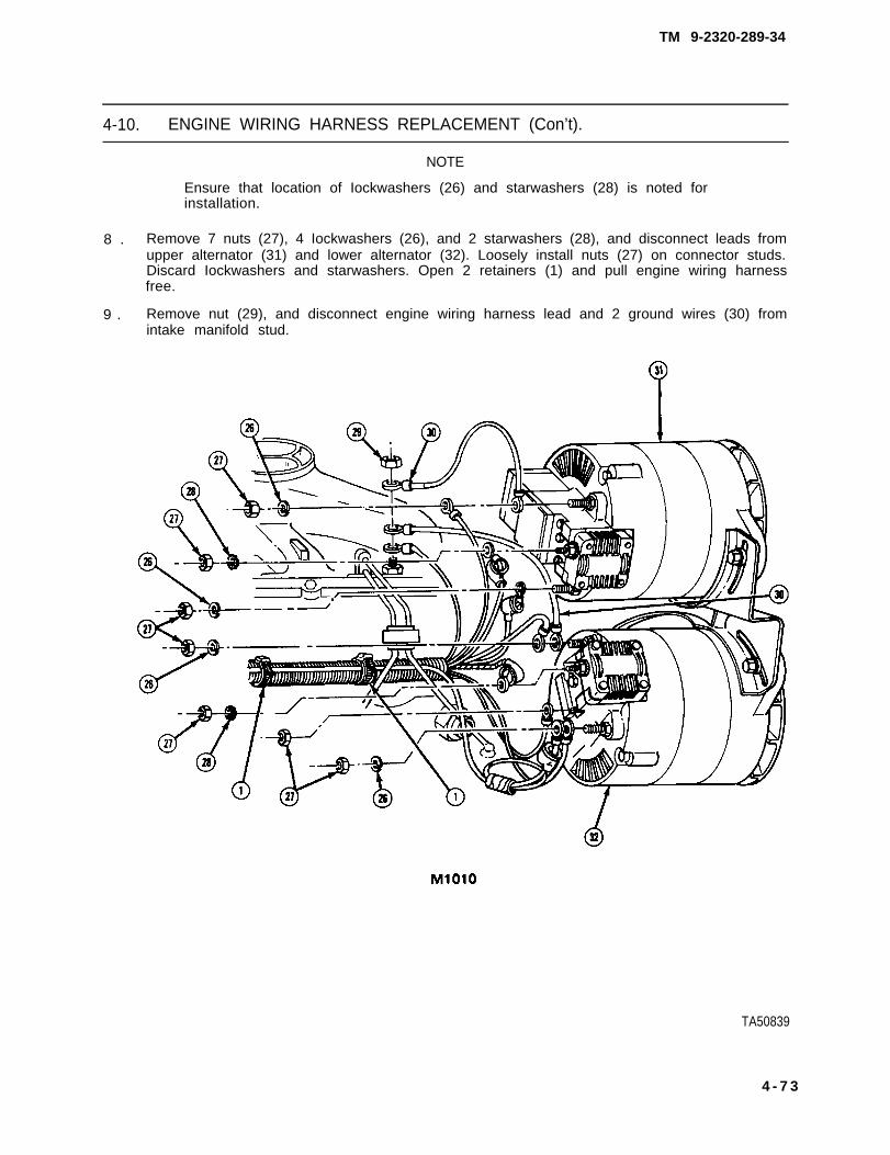
TM 9-2320-289-34
4-10. ENGINE WIRING HARNESS REPLACEMENT (Con’t).
NOTE
Ensure that location of Iockwashers (26) and starwashers (28) is noted forinstallation.
8 . Remove 7 nuts (27), 4 Iockwashers (26), and 2 starwashers (28), and disconnect leads fromupper alternator (31) and lower alternator (32). Loosely install nuts (27) on connector studs.Discard Iockwashers and starwashers. Open 2 retainers (1) and pull engine wiring harnessfree.
9 . Remove nut (29), and disconnect engine wiring harness lead and 2 ground wires (30) fromintake manifold stud.
TA50839
4 - 7 3

TM 9-2320-289-34
4-10. ENGINE WIRING HARNESS REPLACEMENT (Con’t).
10.
11.
12.
1 3 .
Remove bolt and Iockwasher from clip (34), and disconnect lead from compressor (33).Discard Iockwasher.
Disconnect water temperature connector (46) and 4 left side glow plug connectors (45).Disconnect glow plug wiring harness (36), Disconnect oil pressure sending unit connector (35)located behind glow plug wiring harness connector.
Loosen bolt (44) and disconnect engine wiring harness from rear of fuse box (42). Depresssides of terminal “30” on fuse box, and disconnect pink sending unit lead by pulling leadtoward front of connector. Disconnect leads from windshield wiper motor (41). Disconnectcapacitor connector (43).
Remove small nut (37) and large nut (39), and disconnect leads from engine wiring harnessblock (38). Remove 4 nuts and 2 starwashers, and disconnect leads from glow plug relay (40).Discard starwashers.
TA60840
4-74

TM 9-2320-289-34
4-10. ENGINE WIRING HARNESS REPLACEMENT (Con’t).
14.
15.
NOTE
M1010 trucks with retrofit wiring will have additional wiring from enginewiring harness block (38) to current/voltage regulator (49). Ensure thatposition of retrofit wiring is noted for installation.
Remove and discard 6 tie-down straps securing retrofit wiring to engine wiring harness.
Remove 2 screws and current/voltage regulator cover. Remove 5 nuts (51) and Iockwashers,and disconnect leads from current/voltage regulator relay (48). Remove 5 nuts (50) andIockwashers, and disconnect leads from current/voltage regulator (49). Unsnap engine wiringharness from left fenderwell (47). Discard Iockwashers.
TA50841
4-75

TM 9-2320-289-34
4-10. ENGINE WIRING HARNESS REPLACEMENT (Con’t).
1 6 .
1 7 .
1 8 .
Remove 2 screws (53) from clips attransmission (52) . Disconnecttransmission downshift switchconnector (54).
Unsnap all retainers and open allc lamps that hold engine wir ingharness,
Slide right side of engine wiringharness rearward and out from belowfuel in jector l ines. Pull starterconnector out from between rear ofcylinder head next to transmission filltube. Slide left side of engine wiringharness from under fuel injector lines.
CAUTION
Care should be taken during removal of engine wiring harness to preventsnagging it. Failure to follow this caution may result in damage to enginewiring harness.
NOTE
Ensure that position of main lower engine wiring harness is noted forinstallation.
19. Remove engine wiring harness.
b . INSTALLATION
●
●
●
●
NOTE
if connecting all except M1010 engine wiring harness to engineassembly, perform steps 2, 8, 12, 13, 17, and 18.
if connecting M1010 engine wiring harness to engine assembly,perform steps 2, 8 through 11, 13, 17, and 18.
If installing ail except M1010 engine wiring harness, perform steps 1-396 through 8, 12, 13, and 15 through 18.
if installing M1010 engine wiring harness, perform steps 1-11 andsteps 13-18.
TA60642
4-76

TM 9-2320-289-34
4-10. ENGINE WIRING HARNESS REPLACEMENT (Con’t).
1.
2.
3.
4.
NOTE
● Ensure that all connector are seated and locked in place as they areinstalled.
● Ensure that engine wiring harness is secured in appropriate retainersand clamps as it is installed.
Position engine wiring harness in engine compartment.
Slide engine wiring harness under fuel injector lines on left and right side of cylinder head, andcrankcase depression regulator valve bracket on right side. Route starter connector betweenrear of cylinder head next to transmission fill tube.
Connect transmission downshift switch connector (54). Install clips at transmission (52) with 2screws (53).
Snap engine wiring harness to left fenderwell (47). Connect leads to current/voltage regulator(49), and install 5 new Iockwashers and nuts (50). Connect leads to current/voltage regulatorrelay (48), and install 5 new Iockwashers and nuts (51). Install current/voltage regulator coverwith 2 screws.
TA50843
4-77

TM 9-2320-289-34
4-10. ENGINE WIRING HARNESS REPLACEMENT (Con’t).
NOTE
M1010 trucks with retrofit wiring will have additional wiring from enginewiring harness block (38) to current/voltage regulator.
5 . Secure retrofit wiring to engine wiring harness with 6 new tie-down straps.
6 . Connect leads to glow plug relay (40), and install 2 new starwashers and 4 nuts. Connect leadsto engine wiring harness block (38), and install large nut (39) and small nut (37).
7 . Connect windshield wiper motor assembly capacitor connector (43). Connect leads towindshield wiper motor (41 ), Install pink sending unit lead into terminal “30” on fuse box,Connect engine wiring harness to rear of fuse box (42) and tighten bolt (44),
TA50844
4 - 7 8

TM 9-2320-289-34
4-10. ENGINE WIRING HARNESS REPLACEMENT (Con’t).
8 . Connect water temperature connector (46) and 4 left side glow plug connectors (45). Connectoil pressure sending unit connector (35) located behind glow plug wiring harness (36)connector. Connect glow plug wiring harness.
9 . Connect lead to compressor (33), and install clip (34) with new Iockwasher and bolt.
10. Connect 2 ground wires (30) and engine wiring harness lead to intake manifold stud, and installnut (29).
11. Secure engine wiring harness in 2 retainers (1). Remove 7 nuts (27) from connector studs onupper alternator (31) and lower alternator (32). Connect leads to upper alternator and loweralternator, and install 2 new starwashers (28), 4 new Iockwashers (26), and 7 nuts (27).
TA50845
4-79

TM 9-2320-289-34
4-10. ENGINE WIRING HARNESS REPLACEMENT (Con’t).
12.
NOTE
Left side alternator does not havea capacitor (25).
Secure engine wiring harness in 2retainers (1), At right side alternator(24), install capacitor (25) with screw(22) if removed. Connect leads (21)and install 2 nuts (20). Connectvoltage regulator connector (23).Repeat this step for left sidealternator. On left side alternator,also connect lead to “R“ terminal.
TA50846
4 - 8 0

TM 9-2320-289-34
4-10. ENGINE WIRING HARNESS REPLACEMENT (Con’t).
13.
14.
15.
16.
Install new starwasher (18) to intakemanifold stud (19). Connect engineground strap (17), engine wiringharness lead (14), and terminalboard ground (15), and install nut(16).
Connect diagnostic wiring harnessconnector (12).
Connect leads to negative terminalboard center stud (8), and install newstarwasher and nut, Connect leads topositive terminal board studs (7), andinstall 2 new starwashers and nuts.Install terminal board (9) covers.
Connect fuel filter heater connector(10), vacuum switch connector (11),and water sensor connector (13).
17. Connect cold and fast idle switch connector (6), fuel solenoid connector (2), cold advanceswitch connector (3), and fast idle solenoid connector (4).
18. Connect 4 right side glow plug connectors (5),
TA60847
4-81

TM 9-2320-289-34
4-10. ENGINE WIRING HARNESS REPLACEMENT (Con’t).
FOLLOW-ON TASKS:
● Install rear battery box if removed. (See TM 9-2320-289-20)● Install air cleaner. (See TM 9-2320-289-20)● Install starter, (See TM 9-2320-289-20)• Check operation of engine electrical components and windshield wiper motor.
4-82

TM 9-2320-289-34
4-11. GLOW PLUG WIRING HARNESS REPLACEMENT.
This task covers: a. Removal b. Installation
INITIAL SETUP:
Equipment Condition
l Both battery negative cables disconnected. (See TM 9-2320-289-20)
a. REMOVAL
NOTE
Ensure that all leads are tagged for installation.
1. Remove 2 nuts (2) and disconnect leads (1) from glow plug relay (3).
2. Disconnect glow plug wiring harness (11) from engine temperature sensor (10).
TA50848
4 - 8 3

TM 9-2320-289-34
4-11. GLOW PLUG WIRING HARNESS REPLACEMENT (Con’t).
NOTE
Perform step 3 if truck is equipped with heater fuel pump.
3. Disconnect lead (8) from heater fuelpump connector (1 2).
CAUTION
Ensure that “rosebud” retainer is compressed from backside of brakepedal bracket (4) to remove connector. Failure to follow this caution mayresult in damage to connector.
4. Disconnect 6-wire connector (9) under dash. Remove glow plug module (5) from brake pedalbracket (4). Pull glow plug wiring harness (11) and grommet (6) through engine bulkhead (7),and remove.
b. INSTALLATION
1. Install glow plug wiring harness (11) and grommet (6) in engine bulkhead (7). Install glow plugmodule (5) on brake pedal bracket (4). Connect 6-wire connector (9) under dash.
NOTE
Perform step 2 if truck is equipped with heater fuel pump.
2. Untape lead (8) from glow plug wiring harness (11). Connect lead to heater fuel pumpconnector (12).
TA50849
4-84

TM 9-2320-289-34
4-11. GLOW PLUG WIRING HARNESS REPLACEMENT (Con’t).
3 .
4 .
Connect glow plug wiring harness (11) to engine temperature sensor (10).
Connect leads (1) to glow plug relay (3) and install 2 nuts (2).
FOLLOW-ON TASKS:
● Connect both battery negative cables. (See TM 9-2320-289-20)● Check operation of glow plugs.
TA50850
4-85

TM 9-2320-289-34
4-12. CAB HEATER CONTROL, ENGINE DIAGNOSTIC, AND OPEN DOOR BUZZERWIRING HARNESSES REPLACEMENT.
This task covers: a. Removal b. Installation
INITIAL SETUP:
Equipment Condition
• Both battery negative cables disconnected. (See TM 9-2320-289-20)● Instrument cluster plate removed (if removing cab heater control wiring harness or open door
buzzer wiring harness). (See TM 9-2320-289-20)● Instrument panel compartment removed (if removing cab heater control wiring harness or
engine diagnostic wiring harness).
a. REMOVAL
NOTE
● If removing cab heater control wiring harness (4), perform steps 1-5.
● if removing engine diagnostic wiring harness (14), perform steps 6-8.
● if removing open door buzzer wiring harness, perform steps 9 and 10
● Ensure that all leads are tagged for installation,
1. Remove 4 screws and pull out heatercontrol assembly (6).
2. Disconnect cab heater control wiringharness (4) from blower switch (7).Disconnect connector ( 1 ) f r o minstrument panel wiring harness (3)connector.
3. Open 3 clips (2) securing cab heatercontrol wiring harness (4) toinstrument panel wiring harness (3).
TA50851
4-86

TM 9-2320-289-34
4-12. CAB HEATER CONTROL, ENGINE DIAGNOSTIC, AND OPEN DOOR BUZZERWIRING HARNESSES REPLACEMENT (Con’t).
4. Inside engine compartment,d isconnect connector (11) f romblower motor capacitor connector(12). Disconnect cab heater controlwir ing harness (4) f rom blowerresistor (8).
CAUTION
Care shou ld be taken dur ingremoval of cab heater controlwir ing harness (4) to preventsnagging it. Failure to follow thiscaution may result in damage tocab heater control wiring harness.
5. Remove nut (10) and clip (9). Pullcab heater control wiring harness (4)into engine compartment, throughgrommet (5), and remove.
6. Remove 2 screws (20) from diagnostic connector bracket (19), dash panel (16), and wiringharness accessory bracket (15).
7. Remove 4 nuts (13), screws (17), and cap (18). Separate engine diagnostic wiring harness(14) from diagnostic connector bracket (19).
TA50852
4-87

TM 9-2320-289-34
4-12. CAB HEATER CONTROL, ENGINE DIAGNOSTIC, AND OPEN DOOR BUZZERWIRING HARNESSES REPLACEMENT (Con’t).
CAUTION
Care shou ld be taken dur ingremoval o f eng ine d iagnos t i cwiring harness (14) to preventsnagging it. Failure to follow thiscaution may result in damage toengine diagnostic wiring harness.
8 . Inside engine compartment,disconnect engine diagnostic wiringharness (14) from engine wiringharness (22). Pull engine diagnosticwiring harness through grommet (21 )and remove.
9 . Slide open door buzzer wir ingharness (25) off fuse box (24).Remove clip (23) securing open doorbuzzer wiring harness to instrumentpanel wiring harness (3).
10. Disconnect open door buzzer wiringharness (25) from instrument panelwiring harness (3) and remove.
4-88

TM 9-2320-289-34
4-12. CAB HEATER CONTROL, ENGINE DIAGNOSTIC, AND OPEN DOOR BUZZERWIRING HARNESSES REPLACEMENT (Con’t).
b. INSTALLATION
1 .
2 .
3 .
4 .
5 .
● If installingand 2.
● if installing
● If installing
NOTE
open door buzzer wiring harness (25), perform steps 1
engine diagnostic wiring harness (14), perform steps 3-5.
cab heater control wiring harness, perform steps 6-10.
. Ensure that all connectors are seated and locked in place as they areinstalled.
Connect open door buzzer wiring harness (25) to instrument panel wiring harness (3).
Secure open door buzzer wiring harness (25) to instrument panel wiring harness (3) with clip(23). Slide open door buzzer wiring harness onto fuse box (24).
Inside engine compartment, push engine diagnostic wiring harness (14) through grommet(21 ). Connect engine diagnostic wiring harness to engine wiring harness (22).
NOTE
Ensure that indexing pin on front of engine diagnostic wiring harness (14)is installed in 12 o’clock position.
Assemble engine diagnostic wiring harness (14) and diagnostic connector bracket (19). installcap (18), 4 screws (17), and nuts (13).
Install diagnostic connector bracket (19) and wiring harness accessory bracket (15) on dashpanel (16) with 2 screws (20).
TA60854
4-89

TM 9-2320-289-34
4-12. CAB HEATER CONTROL, ENGINE DIAGNOSTIC, AND OPEN DOOR BUZZERWIRING HARNESSES REPLACEMENT (Con’t).
6 .
7 .
Inside engine compartment, push cabheater control wiring harness (4)through grommet (5). Install clip (9)and nut (10).
Connect cab heater control wiringharness (4) to blower resistor (8).Connect connector (11) to blowermotor capacitor connector (12).
8 .
9 .
10.
Secure cab heater control wiringharness (4) to instrument panel wiringharness (3) with 3 clips (2).
Connect connector (1) to instrumentpanel wiring harness (3) connector.Connect cab heater control wiringharness (4) to blower switch (7).
Install heater control assembly (6)with 4 screws.
FOLLOW-ON TASKS:
● Install instrument panel compartment if removed.● Install instrument cluster plate if removed. (See TM 9-2320-289-20)• Connect both battery negative cables. (See TM 9-2320-289-20)• Check operation of cab heater or open door buzzer.
TA508555
4-90

TM 9-2320-289-34
4 -13 . DIMMER AND IGNITION SWITCHES REPLACEMENT.
This task covers: a. Removal b. Installation
INITIAL SETUP:
Equipment Condition
● Instrument cluster plate removed, (See TM 9-2320-289-20)
a . R E M O V A L
NOTE
If removing dimmer switch, perform steps 1-4.
1. Mark cable clip (3) location on right side of steering column (4) for installation, Disconnectcable clip. Remove 2 screws (2) and transmission position indicator (1).
2. Remove 2 nuts (6), washers (7), and support (5). Lower steering column (4).
4-91

TM 9-2320-289-34
4 -13 . DIMMER AND IGNITION SWITCHES REPLACEMENT (Con’t).
NOTE
Ensure that connectors are tagged for installation.
3 . Disconnect dimmer switch connector (11) from dimmer switch (10), and ignition switchconnector (8) from ignition switch (9),
4 . Remove nut (12), screw (13), anddimmer switch (10) from ignitionswitch (9). Remove dimmer switchactuating rod.
5 . Remove stud (14) and ignition switch(9) from steering column (4),
b. INSTALLATION
NOTE
lf installing dimmer switch,perform steps 2-5.
1. Install ignition switch (9) on steeringcolumn (4) with stud (14),
2 . Install dimmer switch (10) actuatingrod, Install dimmer switch on ignitionswitch (9) with screw (13) and nut(12),
3 . Connect dimmer switch connector(11) to dimmer switch (10), andigni t ion switch connector (8) toignition switch (9).
TA50857
4-92

TM 9-2320-289-34
4-13. DIMMER AND IGNITION SWITCHES REPLACEMENT (Con’t).
4. Raise steering column (4), and installsupport (5) with 2 washers (7) andnuts (6).
5. Install transmission position indicator(1) with 2 screws (2). Connect cableclip (3) to steering column (4). Checkindicator needle for proper positionand adjust as required.
FOLLOW-ON TASKS:
.
● Install instrument cluster plate. (See TM 9-2320-289-20)● Check operation of lights and starter system.
TA50858
4-93

TM 9-2320-289-34
4-14. DIRECTIONAL SIGNAL SWITCH REPLACEMENT.
This task covers: a. Removal b. Installation
INITIAL SETUP:
Equipment Condition Materials/Parts
● Hazard warning control removed. • One upper shaft retainer(See TM 9-2320-289-20)
• Steering wheel and directional signal leverremoved. (See TM 9-2320-289-20)
Tools/Test Equipment
● Lock plate compressor● Snapring pliers
a. REMOVAL
1. Pry lock plate (5) cover from lock plate and remove from steering column (4).
2. Install lock plate compressor (2). Turn nut (1) until upper shaft retainer (3) can be removed.Remove and discard upper shaft retainer. Remove lock plate compressor and lock plate (5).
3. Slide canceling cam, upper bearing preload spring, and thrust washer from steering shaft (7).Remove 4 mounting screws from directional signal switch (6).
TA50859
4-94

TM 9-2320-289-34
4-14. DIRECTIONAL SIGNAL SWITCH REPLACEMENT (Con’t).
4 . Remove 4 screws (11) and steering column filler (10) from dash panel (9). Remove 2 screws(12) and steering column filler (8).
5 . Remove 2 nuts (14), washers (15),and support (13).
TA50860
4 - 9 5

TM 9-2320-289-34
4-14. DIRECTIONAL SIGNAL SWITCH REPLACEMENT (Con’t).
6 . Remove switch harness (18) protector. Disconnect connector (17) from instrument panelwiring harness (16) and unsnap from steering column (4),
7. Attach guide wire securely to connector (17). Pull directional signal switch (6) with switchharness (18) and guide wire through steering column (4) until connector is out of steeringcolumn, Disconnect guide wire and leave in place for installation.
b. INSTALLATION
1. Attach guide wire securely to connector (17), Pull guide wire with switch harness (18) throughsteering column (4) until connector is out of steering column. Disconnect and remove guidewire,
2. Snap connector (17) onto steering column (4) and connect to instrument panel wiring harness(16). Install switch harness (18) protector.
TA50861
4-96

TM 9-2320-289-34
4-14. DIRECTIONAL SIGNAL SWITCH REPLACEMENT (Con’t).
3 . Install support (13) with 2 washers (15) and nuts (14).
4 . Install steering column filler (8) with 2 screws (12), Install steering column filler (10) on dashpanel (9) with 4 screws (11).
TA50862
4-97

TM 9-2320-289-34
4-14. DIRECTIONAL SIGNAL SWITCH REPLACEMENT (Con’t).
5 . Install directional signal switch (6) with 4 mounting screws, Slide thrust washer, upper bearingpreload spring, and canceling cam onto steering shaft (7).
6 . Install lock plate (5) and new upper shaft retainer (3) on steering shaft (7). Install lock platecompressor (2). Turn nut (1) until steering shaft groove is visible. Install upper shaft retainer ingroove, Remove lock plate compressor,
7 . Snap lock plate (5) cover into position on lock plate.
FOLLOW-ON TASKS:
● Install steering wheel and directional signal lever, (See TM 9-2320-289-20)● Install hazard warning control, (See TM 9-2320-289-20)• Check operation of directional signals.
TA50863
4-98

TM 9-2320-289-34
CHAPTER 5TRANSMISSION AND TRANSFER CASE MAINTENANCE
S e c t i o n 1 . T R A N S M I S S I O N M A I N T E N A N C E
5 - 1 . TRANSMISSION MAINTENANCE INDEX.
ParagraphNumber
5-2.5-3.
5-4.
5 -5 .5 -6 .5-7.
5-8.5-9.5-10.5-11.5-12.5-13.5-14.5-15.5-16.5-17.
5-18.5-19.
Procedures
Transmission Linkage Maintenance . . . . . . . . . . . .. . . . . . . . . . . .Vacuum Modulator Assembly and Fill TubeAssembly Replacement . . . . . . . . . . . . . . . . . . . . . . . .. . . . . . . . . .Transmission Oil Cooler Supply and Return PipesMaintenance . . . . . . . . . . . . . . . . . . . . . . . . . . . . .Governor Assembly Maintenance . . . . . . . . . . . . . . . . . . . . . . . . . . .Transmission Downshift Electrical Connector Replacement . . . . . .Transmission Control Valve Assembly and DetentSolenoid Maintenance . . . . . . . . . . . . . . . . . . . . . . . . . . . . . .Transmission Parking Lock Replacement . . . . . .. . . . . . . . . . . . . .Rear Servo Assembly Maintenance . . . . . . . . . . . . . . . . . . . . . . . . .Front Servo Assembly Maintenance . . . . . . . . . . . . . . . . . . . . . . . . .Transmission Oil Pressure Testing . . . . . . . . . . . . . . . . . . . . . . . . . .Transmission and Torque Converter Maintenance . . . . . . . . . . . . .Installing and Removing Transmission from Holding Fixture . . . . . .Checking Front Unit End Play.. . . . . . . . . . . . . . . . . . . . . . . . . . . . .Transmission Oil Pump Maintenance . . . . . . . . . . . . . . . . . . . . . . . .Transmission Forward Clutch Assembly Maintenance . . . . . . . . . . .Transmission Direct Clutch Assembly and Front BandMaintenance . . . . . . . . . . . . . . . . . . . . . . . . . . . . . . . . . . . . . . . . . Checking Rear Unit End Play... . . . . . . . . . . . . . . . . . . . . . . . . . . . .Transmission Intermediate Clutch, Center Support Assemblyand Gear Unit, and Rear Band Maintenance . . . . . . . . . . . . . . . . . .
PageNumber
5-2
5-6
5-165-205-24
5-265-395-445-495-525-565-655-685-725-82
5-925-103
5-106
Change 2 5-1

TM 9-2320-289-34
5-2. TRANSMISSION LINKAGE MAINTENANCE.
This task covers: a . Removal c . Installationb. Cleaning and Inspection d. Adjustment
INITIAL SETUP:
Equipment Condition MaterialslParts
● Truck on level ground with wheels chocked. • One wave washer● Dry cleaning solvent
(Item 23, Appendix B)
Too/s/Test Equipment Genera/ Safety Instructions
● Torque wrench ● Dry cleaning solvent is flammable andmust not be used near open flame.Use only in a well-ventilated area.
NOTE
If disconnecting linkage from transmission,
1 . Remove spring clip retainer (5) at upper end of rod (1).
perform step 3.
Remove rod from upper shift lever(3), Remove bushing (2) and insulator (4) if damaged.’ Discard bushing and
NOTE
Position of wave washer (17) should be noted for installation.
insulator.
2 . While supporting rod (1), remove bolt (18), and wave washer (17). Remove rod and swivel(1 6). Discard wave washer.
3 . Remove spring clip retainer (11) from lever (19) assembly and remove lever assembly fromtransmission lever (10),
4 . Remove lever (19) assembly from bracket (7). Remove bushing (15), washer (14), and spring(13) from lever assembly.
5 . Remove nut (12) and transmission lever (10) from transmission if damaged. Remove 2 nuts(8), bolts (6), lockwashers (9), and bracket (7) from frame if damaged. Discard Iockwashers.
5-2

TM 9-2320-289-34
5-2. TRANSMISSION LINKAGE MAINTENANCE (Con’t).
b. CLEANING AND INSPECTION
WARNING
Dry cleaning solvent P-D-680 is toxic and flammable. Always wearprotective goggles and gloves and use only in a well-ventilated area. Avoidcontact with skin, eyes, and clothes and DO NOT breathe vapors. DO NOTuse near open flame or excessive heat. The solvent’s flash point isI00°F-138°F (38°C-59°C), If you become dizzy while using cleaningsolvent, immediately get fresh air and medical help. If solvent contactseyes, immediately wash your eyes with water and get medical aid.
1 . Clean all parts with dry cleaning solvent.TA50197
5 - 3

TM 9-2320-289-34
5-2. TRANSMISSION LINKAGE MAINTENANCE (Con’t).
2. Inspect linkage and mounting hardware for damage. Replace if damaged.
c. INSTALLATION
NOTE
If connecting linkage to transmission, perform step 3 and ADJUSTMENT,step 3.
1. Install bracket (7) to frame with 2 bolts (6), new Iockwashers (9), and nuts (8) if removed.Install transmission lever (10) to transmission with nut (12) if removed. Tighten nuts to20 Ib,-ft. (27 N.m).
2. Assemble spring (13), washer (14), and bushing (15) to lever (19). Install lever assembly tobracket (7).
TA50198
5 - 4

TM 9-2320-289-34
5-2. TRANSMISSION LINKAGE MAINTENANCE (Con’t),
3 . Install lever (19) assembly to transmission lever (10) with spring clip retainer (11).
4 . Install new insulator (4) and new bushing (2) to upper shift lever (3) if removed. Install rod (1)to upper shift lever with spring clip retainer (5).
5. Install swivel (16) on rod (1) and secure to lever (19) assembly with new wave washer (17)and bolt (18). DO NOT fully tighten bolt,
d. ADJUSTMENT
1. Set transmission lever (10) in “N“(Neutral) pos i t i on by movingtransmission lever clockwise until itstops , then counterclockwise 2detents to “N“ (Neutral) position. Settransmission gearshift l eve r onsteering column in “N“ (Neutral)position.
2. Hold rod (1) tightly in swivel (16) andtighten bolt (18) to 20 Ib.-ft.(27 N.m).
3. Place transmission gearshift lever onsteering column in “P“ (Park)position and check the adjustment.Ensure that transmission gearshiftlever on steering column goes into allpositions and that engine starts in “ P“(Park) or “N” (Neutral) positionsonly. If further adjustments areneeded, loosen pivot bolt (18) andperform ADJUSTMENT, steps 1-3.
FOLLOW-ON TASKS:
● Remove chocks from wheels.
TA50199
5 - 5

TM 9-2320-289-34
5-3. VACUUM MODULATOR ASSEMBLY AND FILL TUBE ASSEMBLYREPLACEMENT.
This task covers: a. Removal c. Installationb. Cleaning and Inspection
INITIAL SETUP:
Equipment Condition Materials/Parts
Both battery negative cables disconnected, ●
(See TM 9-2320-289-20) ●
Vacuum lines removed(See TM 9-2320-289-20)
●
●
One fill tube gasketOne “O“ ring sealDry cleaning solvent(Item 23, Appendix B)Hydraulic fluid (Item 40, Appendix B)Petrolatum (Item 50, Appendix B)
Tools/Test Equipment General Safety Instructions
● 15 mm socket ● Dry cleaning solvent is flammable and● Torque wrench must not be used near open flame.
Use only in a well-ventilated area.
a. REMOVAL
NOTE
● If removing vacuum modulator assembly (2) and valve (4), performstep 1,
• If removing fill tube assembly gasket, perform steps 3 and 4.
• If removing fill tube assembly (1), perform steps 2-5.
• A suitable container should be used to catch hydraulic fluid whendisconnecting fill tube assembly (1) and vacuum modulator assembly(2) from transmission,
1 . Remove bolt (6), retainer (5), and vacuum modulator assembly (2) from transmission (7).Remove “ O“ ring seal (3) and discard, Remove modulator valve (4) from transmission.
5-6 Change 2

TM 9-2320-289-34
5-3. VACUUM MODULATOR ASSEMBLY AND FILL TUBE ASSEMBLYREPLACEMENT (Con’t).
TA701848
Change 2 5 - 7

TM 9-2320-289-34
5-3. VACUUM MODULATOR ASSEMBLY AND FILL TUBE ASSEMBLYREPLACEMENT (Con’t).
2. Using a metric socket, remove 2 bolts (9) and rear engine lifting bracket (8).
3. Remove transmission fluid indicator (11) from fill tube assembly (1), Remove bolt (10) securingfill tube assembly to transmission (7).
4. Remove fill tube assembly (1) from transmission (7). Remove fill tube gasket (12) and discard.
5. Remove fill tube assembly (1),
TA701849
5 - 8 Change 2

TM 9-2320-289-34
5-3. VACUUM MODULATOR ASSEMBLY AND FILL TUBE ASSEMBLYREPLACEMENT (Con’t).
b . CLEANING AND INSPECTION
1 . lnspect vacuum modulator assembly for signs of damage. Turn vacuum modulator assembly sothat vacuum fitting is down. If hydraulic fluid comes out, diaphragm is leaking. Replace vacuummodulator assembly if damaged or leaking.
WARNING
Dry cleaning solvent P-D-680 is toxic and flammable. Always wear protectivegoggles and gloves and use only in a well-ventilated area. Avoid contact withskin, eyes, and clothes and DO NOT breathe vapors. DO NOT use near openflame or excessive heat. The solvent’s flash point is 100°F-138°F(38°C-59°C). If you become dizzy while using cleaning solvent,immediately get fresh air and medical help. If solvent contacts eyes,immediately wash your eyes with water and get medical aid.
2 . Clean vacuum modulator assembly with soap and water. Clean modulator valve and fill tubeassembly in dry cleaning solvent.
3 . Inspect modulator valve for damage. Place modulator valve in transmission bore and check forfree operation. If modulator valve binds in transmission bore or is damaged, replace modulatorvalve.
4 . Inspect fill tube assembly and replace if damaged.TA701850
Change 2 5 - 9

TM 9-2320-289-34
5-3. VACUUM MODULATOR ASSEMBLY AND FILL TUBE ASSEMBLYREPLACEMENT (Con’t).
c . INSTALLATION
1.
2 .
3 .
NOTE
● If installing fill tube assembly gasket (12), perform steps 1, 3, and 5.
● If installing fill tube assembly (1), perform steps 1-5.
● If installing vacuum modulator assembly and modulator valve, performstep 6.
Lightly coat new fill tube gasket (12) with petrolatum and install in transmission (7).
From engine compartment, install fill tube assembly (1),
Install fill tube assembly (1) in transmission (7).
TA701851
5 - 1 0 Change 2

TM 9-2320-289-34
5-3. VACUUM MODULATOR ASSEMBLY AND FILL TUBE ASSEMBLYREPLACEMENT (Con’t).
4 . Using a metric socket, install rear engine lifting bracket (8) with 2 bolts (9).
5 . Install bolt (10) securing fill tube assembly (1) to transmission (7). Install transmission fluidindicator (11).
TA701852
Change 2 5 - 1 1

TM 9-2320-289-34
5 - 3 . VACUUM MODULATOR ASSEMBLY AND FILL TUBE ASSEMBLYREPLACEMENT (Con’t).
16. Install modulator valve (4) in transmission (7) bore with stem end out. Install new “O“ ring seal(3) and vacuum modulator assembly (2) with retainer (5) and bolt (6). Tighten bolt to 20 Ib,-ft.(27 N.m).
FOLLOW-ON TASKS:
● Install vacuum lines. (See TM 9-2320-289-20)• Connect both battery negative cables. (See TM 9-2320-289-20)Ž Check hydraulic fluid level, (See LO 9-2320-289-12)
Pages 5-13 through 5-15 have been rescinded.
TA701853
5-12 Change 2

TM 9-2320-289-34
5-3. VACUUM MODULATOR ASSEMBLY, VACUUM LINES, AND FILL TUBEASSEMBLY REPLACEMENT (Con’t).
TA50205
5-13

TM 9-2320-289-34
5-3. VACUUM MODULATOR ASSEMBLY, VACUUM LINES, AND FILL TUBEASSEMBLY REPLACEMENT (Con’t).
9. Install bolt (22) securing fill tube assembly (15) to transmission (14). Install transmission fluidindicator (4).
10. Install modulator valve (10) in transmission (14) bore with stem end out. Install new “O” ringseal (9) and vacuum modulator assembly (8) with retainer (11) and bolt (12). Tighten bolt to20 Ib.-ft. (27 N.m).
1 1 . Connect hose (13) to vacuum modulator assembly (8),
TA50206
5-14

TM 9-2320-289-34
5-3. VACUUM MODULATOR ASSEMBLY, VACUUM LINES, AND FILL TUBEASSEMBLY REPLACEMENT (Con’t).
FOLLOW-ON TASKS:
● Install air cleaner if removed. (See TM 9-2320-289-20)● Connect both battery negative cables. (See TM 9-2320-289-20)● Check hydraulic fluid level. (See LO 9-2320-289-12)
TA50207
5-15

TM 9-2320-289-34
5-4. TRANSMISSION OIL COOLER SUPPLY AND RETURN PIPES MAINTENANCE.
This task covers: a.Flushing Pipes c. Installationb. Removal
INITIAL SETUP:
Materials/arts Tools/Test Equipment
● Dry cleaning solvent (Item 23, Appendix B) ● Oil suction pumpŽ 5/18 in. I.D. rubber hose Ž Line wrench
(Item 38, Appendix B)● Hydraulic fluid (Item 40, Appendix B)
General Safety Instructions
• Allow transmission oil cooler pipes to cool before servicing.● Dry cleaning solvent is flammable and must not be used near open flame. Use only in a
well-ventilated area.• Compressed air used for flushing purposes should never exceed 30 psi (207 kPa).
a. FLUSHING PIPES
WARNING
. Allow transmission oil cooler pipes (9 and 10) to cool before attemptingto service. Failure to follow this warning may result in serious burns.
l Dry cleaning solvent P-D-680 is toxic and flammable. Always wearprotective goggles and gloves and use only In a well-ventilated area.Avoid contact with skin, eyes, and clothes and DO NOT breathe vapors.DO NOT use near open flame or excessive heat. The solvent’s flashpoint Is 100°F-138°F (38°C-590C). If you become dizzy while usingcleaning solvent, immediately get fresh air and medical help. If solventcontacts eyes, immediately wash your eyes with water and get medicalaid.
CAUTION
Before a new or overhauled transmission (1) is installed, oil cooler inradiator (4) and transmission oil cooler supply pipe (9) and return pipe(10) must be flushed to rid the system of contamination, Failure toperform this procedure will result in damage to transmission.
NOTE
Suitable containers should be used to catch hydraulic fluid and drycleaning solvent during flushing,
1. Loosen 2 fittings (11) and disconnect transmission oil cooler supply pipe (9) and return pipe (10) from 2 connectors (2) at transmission (1),
2. Place a 5/16 in, I.D. rubber hose over end of transmission oil cooler supply pipe (9) and insertend of hose into dry cleaning solvent.
5-16

TM 9-2320-289-34
5-4 . TRANSMISSION OIL COOLER SUPPLY AND RETURN PIPES MAINTENANCE.
This task covers: a. Flushing Pipes c. Installationb. Removal
INITIAL SETUP:
Materials/Parts Too/s/Test Equipment
● Dry cleaning solvent (Item 23, Appendix B) ● Oil suction pump● 5/16 in. I.D. rubber hose • Line wrench
(Item 38, Appendix B)● Hydraulic fluid (Item 40. Appendix B)
General Safety Instructions
● Allow transmission oil cooler pipes to cool before servicing.● Dry cleaning solvent is flammable and must not be used near open flame. Use only in a
well-ventilated area,• Compressed air used for flushing purposes should never exceed 30 psi (207 kPa).
a. FLUSHING PIPES
WARNING
● AIIow transmission oil cooler pipes (9 and 10) to Cool before attemptingto service. Failure to follow this warning may result in serious burns,
● Dry cleaning solvent P-D-680 is toxic and flammable. Always wearprotective goggles and gloves and use only in a well-ventilated area.Avoid contact with skin, eyes, and clothes and DO NOT breathe vapors.DO NOT use near open flame or excessive heat, The solvent’s flashpoint is 100°F-138°F (38°C-590C). If you become dizzy while usingcleaning solvent, immediately get fresh air and medical help, If solventcontacts eyes, immediately wash your eyes with water and get medicalaid.
CAUTION
Before a new or overhauled transmission (1) is installed, oil cooler inradiator (4) and transmission oil cooler supply pipe (9) and return pipe(10) must be flushed to rid the system of contamination. Failure toperform this procedure will result in damage to transmission,
NOTE
Suitable containers should be used to catch hydraulic fluid and drycleaning solvent during flushing.
1. Loosen 2 fittings (11) and disconnect transmission oil cooler supply pipe (9) and return pipe(10) from 2 connectors (2) at transmission (1),
2. Place a 5/16 in. I.D. rubber hose over end of transmission oil cooler supply pipe (9) and insertend of hose into dry cleaning solvent.
5-16

TM 9-2320-289-34
5-4. TRANSMISSION OIL COOLER SUPPLY AND RETURN PIPES MAINTENANCE(Con’t).
3. Using oil suction pump, flush clean dry cleaning solvent through transmission oil cooler returnpipe (10) until dry cleaning solvent comes out oil cooler return pipe. Continue flushing until drycleaning solvent comes out clean.
4. Remove rubber hose from end of transmission oil cooler supply pipe (9) and place ontransmission oil cooler return pipe (10). Insert end of hose into dry cleaning solvent. Flushclean dry cleaning solvent through transmission oil cooler supply pipe until dry cleaning solventcomes out oil cooler supply pipe. Continue flushing until dry cleaning solvent comes out clean.
WARNING
Compressed air used for flushing purposes should never exceed 30 psi(207 kPa). Use only effective chip guarding and personnel protectiveequipment (goggles/shield, gloves, etc.). Failure to follow this warningmay result in injury to personnel or damage to oil cooler.
5. Remove remaining dry cleaning solvent from oil cooler supply pipe (9), return pipe (10), andfrom oil cooler in radiator (4) with compressed air, and flush with hydraulic fluid.
6. Install transmission oil cooler supply pipe (9) and return pipe (10) at 2 connectors (2). Tighten2 fittings (11).
TA50208
5-17

TM 9-2320-289-34
5-4. TRANSMISSION OIL COOLER SUPPLY AND RETURN PIPES MAINTENANCE(Con’t).
b. REMOVAL
NOTE
I f d i s c o n n e c t i n g o i l c o o l e r s u p p l y p i p e ( 9 ) a n d r e t u r n p i p etransmission (1), perform step 2,
1 . Loosen 2 fittings (3) and disconnect transmission oil cooler supply pipe (9) and return pipe(10) from left side of radiator (4),
2 . Loosen 2 fittings (11) and disconnect transmission oil cooler supply pipe (9) and return pipe(10) from 2 connectors (2) at transmission (1). Remove bolt (8) and clip (6) from torqueconverter cover (7).
3 . Remove pipes from clips (5 and 6) and remove transmission oil cooler supply pipe (9) andreturn pipe (10).
4 . Remove 2 connectors (2) if damaged.
TA50209
5-18

TM 9-2320-289-34
5-4. TRANSMISSION OIL COOLER SUPPLY AND RETURN PIPES MAINTENANCE(Con’t).
c. INSTALLATION 1
NOTE
If connect ing oi l cooler supply pipe (9) and return pipe (10) totransmission (1), perform steps 1, 3, and 4.
1. If removed, install 2 connectors (2) to transmission (1). Install transmission oil cooler returnpipe (10) to top connector and transmission oil cooler supply pipe (9) to bottom connector.Tighten 2 fittings (11).
2. Connect transmission oil cooler return pipe (10) to top of radiator (4) and transmission oilcooler supply pipe (9) to bottom of radiator. Tighten 2 fittings (3).
3. Install clip (6) to oil cooler supply pipe (9) and return pipe (10). Install oil cooler supply pipeand return “pipe to clip (5) at engine oil pan.
4. Install clip (6) to torque converter cover (7) with bolt (8).
FOLLOW-ON TASKS:
● Check hydraulic fluid level. (See LO 9-2320-289-12)
5-19

TM 9-2320-289-34
5-5. GOVERNOR ASSEMBLY MAINTENANCE.
This task covers: a. Removal d. Assemblyb. Disassembly e. Installationc. Cleaning and Inspection
INITIAL SETUP:
Equipment Condition Materials/Parts
• Transfer case in “2H.” ●
●
Tools/Test Equipment ●
● Torque wrench●
General Safety Instructions
● Dry cleaning solvent is flammable and must not bewell-ventilated area.
One gasketTwo pinsDry cleaning solvent(Item 23, Appendix B)Hydraulic fluid (Item 40,
used near open flame.
• Compressed air used for cleaning purposes should never exceed 30 psi (207
Appendix B)
Use only in a
kPa),
a. REMOVAL
NOTE
A suitable container should be used to catch hydraulic fluid whenremoving governor cover (2) and governor assembly (4).
1. Remove 4 bolts (1) and governor cover (2) from transmission case (5). Remove gasket (3)and discard. Remove governor assembly (4) from bore of transmission,
TA50210
5-20

TM 9-2320-289-34
5-5. GOVERNOR ASSEMBLY MAINTENANCE (Con’t).
b. DISASSEMBLY
1.
2 .
3 .
Cut off end of each pin (6). Remove2 pins, thrust cap (14), 2 primaryweights (7), secondary weights (9),and springs (8). Discard pins.
Carefully remove valve (13) fromsleeve (10).
If driven gear (12) is worn or loose onsleeve (10), drive out Iockpin (11)and remove driven gear. DiscardIockpin and driven gear.
c. CLEANING AND INSPECTION I
WARNING
l Dry cleaning solvent P-D-680 is toxic and flammable. Always wearprotective goggles and gloves and use only in a well-ventilated area.Avoid contact with skin, eyes, and clothes and DO NOT breathe vapors.DO NOT use near open flame or excessive heat. The solvent’s flashpoint is 100°F-138°F (38°C-59°C). If you become dizzy while usingcleaning solvent, immediately get fresh air and medical help. If solventcontacts eyes, immediately wash your eyes with water and get medicalaid.
. Compressed air used for cleaning purposes should never exceed 30 psi(207 kPa). Use only effective chip guarding and personnel protectiveequipment (goggles/shield, gloves, etc.). Failure to follow this warningmay result in injury to personnel.
1. Clean all disassembled components with dry cleaning solvent. Dry with compressed air andblow out all passages.
2. Inspect all disassembled components for damage. If any component is damaged, replacegovernor assembly as a unit.
TA50211
5-21

TM 9-2320-289-34
5-5. GOVERNOR ASSEMBLY MAINTENANCE (Con’t).
3. Install sleeve in bore of transmission and inspect for free operation in bore. Inspect valve forfree operation in bore of sleeve. If sleeve or valve bind, replace governor assembly as a unit.
4. If a new governor assembly has been obtained, install in bore of transmission and inspect forfree operation, If governor assembly binds in bore, replace transmission case,
d. ASSEMBLY
1 . If removed install new driven gear (12) on sleeve (10). Press driven gear in until it is almostseated, using a socket, with governor assembly (4) supported in an arbor press with two7/64 in. (2.78 mm) plates in the exhaust openings (16). Remove any shavings from driven gearhub and press in until it is seated.
CAUTION
Shaft portion of driven gear (12)s h o u l d b e supported wheninstalling new Iockpin (11). Failureto follow this caution may result indamage to driven gear.
2 . Using a 1/8 in. drill, drill a new pin hole90 degrees from the existing one insleeve (10). Install new Iockpin (11)through new hole in driven gear andsleeve so that ends are just below topof hole. Clean driven gear and sleeveassembly to remove any shavingsthat may have collected.
3 . Install valve (13) into bore of sleeve(10). Install 2 primary weights (7),secondary weights (9), springs (8),and thrust cap (14) on sleeve. Alinepin holes and install 2 new pins (6).Crimp ends of pins to prevent themfrom falling out.
4 . Lubricate governor assembly withhydraulic fluid and ensure that weightassemblies (7 and 9) operate freelyon 2 pins (6) and that valve (13)operates freely in bore of sleeve(10).
5 . Inspect valve entry opening (15) with weights held all the way outward. The opening should be0.020 in. (0.508 mm) minimum, Inspect valve exhaust opening (16) with weights held all theway inward, The opening should be 0,020 in. (0.508 mm) minimum. If valve entry and exhaustopenings are not within specifications, replace governor assembly (4),
TA50212
5 - 2 2

TM 9-2320-289-34
5-5. GOVERNOR ASSEMBLY MAINTENANCE (Con’t).
e. INSTALLATION
1. Install governor assembly (4) in bore of transmission case (5).
2. Install governor cover (2) with new gasket (3) and 4 bolts (1). Tighten bolts to 20 Ib.-ft.(27 N.m).
FOLLOW-ON TASKS:
● Check hydraulic fluid level. (See LO 9-2320-289-12)TA50213
6 - 2 3

TM 9-2320-289-34
5-6. TRANSMISSION DOWNSHIFT ELECTRICAL CONNECTOR REPLACEMENT.
This task covers: a. Removal b. Installation
INITIAL SETUP:
Equipment Condition Materials/Parts
● Transmission filter assembly removed. ● One “O“ ring seal(See TM 9-2320-289-20) ● Hydraulic fluid (Item 40, Appendix B)
a. REMOVAL
1. Disconnect engine wiring harness connector (5) from downshift electrical connector (1).Disconnect detent solenoid wire (2) from end of downshift electrical connector insidetransmission case (4),
2. Compress prongs on downshift electrical connector (1) and remove from transmission case(4) .
3. Remove “O“ ring seal (3) from downshift electrical connector (1) and discard.
TA50214
5-24

TM 9-2320-289-34
5-6. TRANSMISSION DOWNSHIFT ELECTRICAL CONNECTOR REPLACEMENT(Con’t).
b. INSTALLATION
1 . Lubricate new “O” ring seal (3) with hydraulic fluid and install in downshift electrical connector(1) groove.
2 . Install downshift electrical connector (1) with lock tabs pointing into transmission case (4) andlocator tabs in notch on side of transmission case.
3 . Connect detent solenoid wire (2) and engine wiring harness connector (5) to downshiftelectrical connector (1).
FOLLOW-ON TASKS:
● Install transmission filter assembly. (See TM 9-2320-289-20)
5-25

TM 9-2320-289-34
5-7. TRANSMISSION CONTROL VALVE ASSEMBLY AND DETENT SOLENOIDMAINTENANCE.
This task covers: a. Removal d. Assemblyb. Disassembly e. Installationc. Cleaning and Inspection
INITIAL SETUP:
Equipment Condition Materials/Parts
● Transmission filter and intake pipe removed,(See TM 9-2320-289-20)
Tools/Test Equipment● Accumulator piston compressor, J-22269-1● Torque wrench
Personnel Required● MOS 63W (2)
●
●
●
●
One case gasketOne control valve body gasketOne detent solenoid gasketDry cleaning solvent(Item 23, Appendix B)Crocus cloth (Item 18, Appendix B)Hydraulic fluid (Item 40, Appendix B)Lubricating oil (Item 47, Appendix B)Petrolatum (Item 50, Appendix B)
General Safety Instructions
● Dry cleaning solvent is flammable and must not be used near open flame. Use only in awell-ventilated area.
● All valves are under spring tension. Wear goggles and use caution during removal andinstallation of springs.
a. REMOVAL
NOTE
• If removing detent roller and spring assembly (2), perform step 1.
• If removing detent solenoid, perform step 5.
● If removing control valve spacer plate and check balls, perform steps1-6.
1. Remove bolt (4) and detent roller and spring assembly (2) from control valve assembly (3).
5-26

TM 9-2320-289-34
5-7. TRANSMISSION CONTROL VALVE ASSEMBLY AND DETENT SOLENOIDMAINTENANCE (Con’t).
CAUTION
Ensure that manual valve (7) doesnot fall out of its bore in controlvalve assembly (3). Fai lure tofollow this caution may result indamage to manual valve.
2 . Remove 10 remaining bolts (6). Liftup on 2 governor pipes (5) andremove control valve assembly (3)and governor pipes as a unit.
NOTE
Governor screen assembly (8) maybe found in governor feed pipehole (9) or in governor pipe (5).Governor screen assembly mustbe installed In same hole fromwhich it was removed,
3 . Mark feed pipe hole (9) and removegovernor screen assembly (8).
4 . Remove 2 governor pipes (5) fromcontrol valve assembly (3). Removecontrol valve body gasket anddiscard.
TA50215
5-27

TM 9-2320-289-34
5-7. TRANSMISSION CONTROL VALVE ASSEMBLY AND DETENT SOLENOIDMAINTENANCE (Con’t).
5. Disconnect detent solenoid wire (11)at connector (10). Remove 2 screws(13) and remove detent solenoid(12). If present, remove detentsolenoid gasket and discard.
NOTE
If transmission is in truck, controlvalve spacer plate (14) must belowered in a level plane so thatcheck balls (15) do not fall out.Then check balls are removedfrom control valve spacer plate.
6. Remove control valve spacer plate(14) and case gasket. Discard casegasket. Remove 6 check balls (15).
TA50216
5-28

TM 9-2320-289-34
5-7. TRANSMISSION CONTROL VALVE ASSEMBLY AND DETENT SOLENOIDMAINTENANCE (Con’t).
b. DISASSEMBLY
WARNING
All valves are under spring tension. Wear goggles and use caution duringremoval of springs. Maintain pressure against valves while removingretaining pins. Failure to follow this warning may result in injury topersonnel.
CAUTION
Use caution to ensure that control valve assembly (3), valves, bushings,and springs are not scratched, nicked, or gouged during disassembly.Failure to follow this caution will result in transmission malfunction.
NOTE
All components should be marked as they are disassembled so that theymay be properly assembled.
1. Position control valve assembly (3) so that oil passages are facing upward and frontaccumulator pocket is toward you.
2. Remove manual valve (7).
3. Compress front accumulator(17) and remove retaining ring
4 . Remove f ron t accumula to r(17) and spring (19).
TA50217
5-29

TM 9-2320-289-34
5-7. TRANSMISSION CONTROL VALVE ASSEMBLY AND DETENT SOLENOIDMAINTENANCE (Con’t).
NOTE
1-2 regulator valve (23) and spring (22) may be inside of 1-2 modulatorbushing (24).
5 . Remove retaining pin (36), 1-2 modulator bushing (24), 1-2 regulator valve (23) amd spring(22), 1-2 detent valve (21), and 1-2 shift valve (20).
6 . Remove retaining pin (35), 2-3 shift valve spring (26), 2-3 modulator brushing (27) with 2-3modulator valve (25) inside, 2-3 intermediate spring (28), and 2-3 shift valve (29).
7. Remove retaining pin (34), 3-2 bore plug (30), 3-2 valve spring (31), 3-2 spacer (32), and 3-2shift valve (33).
TA50218
5 - 3 0

TM 9-2320-289-34
5-7. TRANSMISSION CONTROL VALVE ASSEMBLY AND DETENT SOLENOIDMAINTENANCE (Con’t).
8. Remove retaining pin (43), detent bore plug (37), detent valve (38), detent regulator valve(39), detent regulator valve spring (41), and detent spacer (40).
9. Remove retaining pin (42), 1-2 bore plug (46), 1-2 accumulator valve (45), and 1-2 primaryaccumulator spring (44).
c . CLEANING AND INSPECTION
WARNING
Dry cleaning solvent P-D-680 is toxic and flammable. Always wearprotective goggles and gloves and use only. in a well-ventilated area. Avoidcontact with skin, eyes, and clothes and DO NOT breathe vapors. DO NOTuse near open flame or excessive heat. The solvent’s flash point is100°F-138°F (38°C-59°C). if you become dizzy while using cleaningsolvent, immediately get fresh air and medical help. If solvent contactseyes, immediately wash your eyes with water and get medical aid.
TA50219
5-31

TM 9-2320-289-34
5-7. TRANSMISSION CONTROL VALVE ASSEMBLY AND DETENT SOLENOIDMAINTENANCE (Con’t).
1 .
2 .
3 .
4 .
5 .
6 .
CAUTION
Use caution to ensure that valves do not bump together, Failure to followthis caution may result in damage to valves.
Clean control valve body, valves, and other parts in dry cleaning solvent.
Inspect all valves for damage and free movement in their bores. If burrs are present, removethem by polishing with crocus cloth and light lubricating oil. Be careful to not round offshoulders of valves. All valves should fall freely of their own weight with a slight tapping actionon the valve body, If manual valve is damaged or binds in its bore, replace. If any other valvesare damaged or bind in their bores, replace control valve assembly.
Inspect all bushings for damage and free movement in their bores. Replace control valveassembly if bushings are damaged or bind in their bores.
Inspect control valve body and springs for damage. Replace control valve assembly if eitherare damaged.
If damaged, remove oil seal ring (18)from front accumulator piston (17)and discard.
Inspect front accumulator piston fordamage. Replace if damaged.
TA50220
5 - 3 2

TM 9-2320-289-34
5-7. TRANSMISSION CONTROL VALVE ASSEMBLY AND DETENT SOLENOIDMAINTENANCE (Con’t).
d ASSEMBLY
WARNING
All valves are under spring tension. Wear goggles and use caution duringinstallation of springs. Maintain pressure against valves while installingretaining pins. Failure to follow this warning may result in injury topersonnel.
CAUTION
• Use caution to ensure that control valve assembly (3). valves,bushings, and springs are not scratched, nicked, or gouged duringassembly. Failure to follow this caution will result in transmissionmalfunction.
● Ensure that front accumulator piston spring (19) and front accumulatorpiston (17) are alined with bore and that oil seal ring (18) does notcatch on lip of bore when installing front accumulator piston. Failure tofollow this caution may result in damage to oil seal ring.
NOTE
All components should be lightly coated with hydraulic fluid as they areassembled.
1 . install new oil seal ring (18) to front accumulator piston (17) if removed. Position frontaccumulator piston spring (19) and front accumulator piston into control valve body andcompress. Install retaining ring (1 6). Check to ensure that there is free movement of frontaccumulator piston.
5-33

TM 9-2320-289-34
5-7. TRANSMISSION CONTROL VALVE ASSEMBLY AND DETENT SOLENOIDMAINTENANCE (Con’t).
2 .
3 .
4 .
Install 1-2 primary accumulator spring (44) and 1-2 accumulator valve (45), stem end out, intobore. Install 1-2 bore plug (46) into bore with hole end facing out. Install grooved retaining pin(42) with grooves to outside.
Install detent spacer (40) inside detent regulator valve spring (41). Install both ensuring thatdetent regulator valve spring seats in bottom of bore.
Install detent regulator valve (39), stem end out, and detent valve (38), small land first, intobore. Install detent bore plug (37), hole end out. Install retaining pin (43).
5.
6.
7.
8.
9.
Install 3-2 shift valve (33). Install 3-2 spacer (32) inside 3-2 valve spring (31) and install bothinside bore,
Compress 3-2 valve spring (31) and install 3-2 bore plug (30), hole end out, Install retaining pin(34) .
Install 2-3 intermediate spring (28) in open end of 2-3 shift valve (29). Install both in boreensuring that valve seats” in bottom of bore.
Install 2-3 modulator valve (25), hole end first. into 2-3 modulator bushing (27) and install bothin bore.
I n s t a l l 2 - 3 s h i f t v a l v e s p r i n g ( 2 6 ) i n h o l e i n 2 - 3 s h i f t v a l v espring and install retaining pin (35).
TA50221
5-34

TM 9-2320-289-34
5-7. TRANSMISSION CONTROL VALVE ASSEMBLY AND DETENT SOLENOIDMAINTENANCE (Con’t).
1 0 . Install 1-2 shift valve (20), stem end out, ensuring that valve seats in bottom of bore.
1 1 . Install spring (22) into small end of 1-2 regulator valve (23). Install assembled spring and valveinto 1-2 modulator bushing (24). Install 1-2 detent valve (21), hole end first, into 1-2 modulatorbushing.
12. Install 1-2 modulator bushing (24) assembly into bore and compress enough to install retainingpin (36).
13 . Install manual valve (7).
TA50222
5 - 3 5

TM 9-2320-289-34
5-7. TRANSMISSION CONTROL VALVE ASSEMBLY AND DETENT SOLENOIDMAINTENANCE (Con’t).
e. INSTALLATION
NOTE
● If installing detent roller andspring assembly (2), performstep 8.
● If installing detent solenoid(12), perform steps 3 and 9.
● I f t ransmission is in t ruck,petrolatum should be applied tocheck balls (15) to retain them.
1 . Install 6 check balls (15) in ball seatpockets in transmission case.
NOTE
Case gasket should not beconfused with control valve spacerplate (14). Case gasket is marked“ c . ”
2. Aline new case gasket and controlvalve spacer plate (14) and installwith case gasket against transmissioncase.
3. Install new detent solenoid gasket anddetent solenoid (12) with 2 screws(13). DO NOT fully tighten screws.
NOTE
Cont ro l va lve body gaske t i smarked with a “V.”
4. Install new control valve body gasket.
5-36

TM 9-2320-289-34
5-7. TRANSMISSION CONTROL VALVE ASSEMBLY AND DETENT SOLENOIDMAINTENANCE (Con’t).
5 . Install open end of governor screenassembly (8) into marked governorfeed pipe hole (9) in transmissioncase. Install 2 governor pipes (5) intoholes in control valve assembly (3).
6. Position control valve assembly (3).Check that governor pipes (5) areproperly fitted into transmission caseholes. Check manual valve (7) toensure that it is indexed with pin oninside detent lever (1), Ensure thatgaskets and spacer plate (14) are notmispositioned.
NOTE
It may be necessary to lightly tapon governor pipes (5) to seat themwhile starting control valve bodybolts (6).
7 . Loosely install 10 bolts (6) to securecontrol valve assemb ly (3 ) totransmission case. Tighten all bolts to10 Ib.-ft. (14 N.m).
8 . Instal l detent rol ler and spr ingassembly (2) with bolt (4). Tightenbolt to 10 Ib.-ft. (14 N.m).
TA50224
5 - 3 7

TM 9-2320-289-34
5 - 7 . TRANSMISSION CONTROL VALVE ASSEMBLY AND DETENT SOLENOIDMAINTENANCE (Con’t) .
9 . Connect detent solenoid wire (11) to connector (10). Tighten 2 screws (13) to 10 Ib.-ft.(14 N.m).
FOLLOW-ON TASKS:
● Install transmission filter and intake pipe. (See TM 9-2320-289-20)
TA50225
5-38

TM 9-2320-289-34
5-8. TRANSMISSION PARKING LOCK REPLACEMENT.
This task covers: a. Removal c. Installationb. Inspection
INITIAL SETUP:
Equipment Condition Materials/Parts
● Detent roller and spring assembly removed. ● One cup plug(See paragraph 5-7) • One manual shaft seal
● RTV sealant (Item 57, Appendix B)
Tools/Test Equipment● Torque adapter● 3/8 in. O.D. rod● 3/4 in. O.D. rod● Torque wrench
a. REMOVAL
1. Remove nut and transmission lever from manual shaft (1).
2. Remove pin (6) securing manual shaft (1) to transmission case, If procedure is beingperformed with transmission in truck, bend pin to remove it.
3. Loosen jamnut (7). Remove inside detent lever (2) from manual shaft (1). Remove jamnut andmanual shaft.
5 - 3 9

TM 9-2320-289-34
5-8. TRANSMISSION PARKING LOCK REPLACEMENT (Con’t).
4 . Remove parking actuator rod (5) and detent lever (2) from transmission case.
5 . Remove manual shaft seal (8) from transmission case
6 . Remove 2 bolts (4) and bracket (3) from transmission
and discard,
case.
7 . Remove parking pawl return spring (10). Remove spring retainer from end of parking pawlshaft (11) inside transmission case. Push parking pawl shaft toward outside of transmissioncase and remove cup plug (12). Discard cup plug.
8 . Remove parking pawl shaft (11) and parking pawl (9).
TA50227
5 - 4 0

TM 9-2320-289-34
5-8. TRANSMISSION PARKING LOCK REPLACEMENT (Con’t).
b . INSPECTION
1. Inspect manual shaft for damage. Replace if damaged,
2 . Inspect inside detent lever for cracks or a loose pin. Replace if cracked or if pin is loose.
3 . Inspect parking actuator rod for damage. Replace if damaged.
4 . Inspect parking pawl for damage. Replace if damaged.
c . INSTALLATION
1 . Position parking pawl (9) with tooth toward center of transmission. Install parking pawl shaft(11) through transmission case and parking pawl. Install spring retainer on end of parking pawlshaft on inside of transmission case.
2 . Coat new cup plug (12) with RTV sealant. Using a 3/8 in. O.D. rod, install new cup plug bydriving it into transmission case, until parking pawl shaft (11) is firmly seated againsttransmission case rib.
3 . Install parking pawl return spring (10) with square end hooked on groove in center of parkingpawl (9) and other end hooked on transmission case.
TA50228
5-41

TM 9-2320-289-34
5-8. TRANSMISSION PARKING LOCK REPLACEMENT (Con’t),
4. Push parking pawl (9) forward, and install bracket (3) with guides over parking pawl. Secure totransmission case with 2 bolts (4). Tighten bolts to 20 Ib. -ft. (27 N.m).
5. Install new manual shaft seal (8) in transmission case and seat it using a 3/4 in, rod.
6. Position parking actuator rod (5) between parking pawl (9) and parking bracket (3), Installinside detent lever (2) to parking actuator rod.
7. Install manual shaft (1) through transmission case and detent lever (2). Install jamnut (7) onend of manual shaft and tighten to 20 Ib.-ft. (27 N.m).
TA50229
5-42

TM 9-2320-289-34
5-8. TRANSMISSION PARKING LOCK REPLACEMENT (Con’t).
8 . Index inside detent lever (2) pin with manual valve (13). Secure manual shaft (1) totransmission case with pin (6), If procedure is being performed with transmission in truck.straighten bent pin after installation.
9. Install transmission lever to manual shaft (1) with nut. Tighten nut. thighten nut to 20 lb.-ft. (27 N.m).
FOLLOW-ON TASKS:
● Install detent roller and spring assembly. (See paragraph 5-7)
TA50230
5-43

TM 9-2320-289-34
5-9. REAR SERVO ASSEMBLY MAINTENANCE.
This task covers: a. Removal d. Cleaning and Inspectionb. Band Apply Pin Selection e. Assembly
Check f. Installationc. Disassembly
INITIAL SETUP:
Equipment Condition Materials/Parts
● Control valve assembly removed. ● One servo(See paragraph 5-7) ● One servo
cover gasketpiston seal
● Two 5/18-18 x 1 in, screws● Dry cleaning solvent
(Item 23, Appendix B). Hydraulic fluid (Item 40, Appendix B)
Tools/Test Equipment General Safety Instructions
● Pin selector gage, J-21370 ● Dry cleaning solvent is flammable and• Gage pin, J-21370-5 must not be used near open flame.● Torque wrench Use only in a well-ventilated area.
a . R E M O V A L
1 . Remove 6 bolts (2) and rear servo cover (1). Remove servo cover gasket and discard.
2 . Remove rear servo assembly (3) from bore. Remove rear accumulator spring (5).
TA50231
5-44

TM 9-2320-289-34
5-9. REAR SERVO ASSEMBLY MAINTENANCE (Con’t).
b. BAND APPLY PIN SELECTION CHECK
1. Install pin selector gage (6) over rear servo bore with smaller diameter of gage pin (7) in servopin bore and secure with two 5/16 -18 x 1 in. screws tightened to 216 lb.-in. (24 N.m). Ensurethat gage pin is free to move up and down in both pin selector gage and servo pin bore andthat steps (8 and 9) of gage pin and machined surface (10) of pin selector gage are facingfront of transmission case.
2. Apply 25 Ib.-ft. (34 N.m) to hex nut on side of pin selector gage (6).
NOTE
Identification rings are located on top of servo pin (4).
3 . Note relation of steps (8 and 9) on gage pin (7) with machined surface (10) on top of pinselector gage (6) and determine proper size servo pin (4) as follows:
(a) If machined surface (10) on top of pin selector gage (6) is even with or above upper step(8) of gage pin (7), long servo pin (3 rings) is required.
(b) If machined surface (10) on top of pin selector gage (6) is between upper step (8) andlower step (9) of gage pin (7), medium servo pin (2 rings) is required.
(c) If machined surface (10) on top of pin selector gage (6) is even with or below lower step(9) on gage pin (7), short servo pin (1 ring) is required.
4 . If new servo pin (4) is required, make note of size. Remove pin selector gage (6) and gage pin(7) from transmission,
TA50232
5-45

TM 9-2320-289-34
5-9. REAR SERVO ASSEMBLY MAINTENANCE (Con’t).
c. DISASSEMBLY
1. Remove rear accumulator piston (11)from rear servo piston (13).
2. Compress rear servo spring (12) andservo pin (4) and remove clip (17)from top of rear servo piston (13).
3. Remove servo pin (4), retainer (14), rear servo spring (12), and washer (15).
4. Remove servo piston n seal (16) from rear servo piston (13) and discard.
TA50233
5-46

TM 9-2320-289-34
5-9. REAR SERVO ASSEMBLY MAINTENANCE (Con’t).
d . CLEANING AND INSPECTION
WARNING
Dry cleaning solvent P-D-680 Is toxic and flammable. Always wearprotective goggles and gloves and use only in a well-ventilated area, Avoidcontact with skin, eyes, and clothes and DO NOT breathe vapors. DO NOTuse near open flame or excessive heat. The solvent’s flash point is100°F-138°F (38°C-59°C), If you become dizzy while using cleaningsolvent, immediately get fresh air and medical help. If solvent contactseyes, immediately wash your eyes with water and get medical aid.
1. Clean all removed components in dry cleaning solvent.
2. Inspect rear accumulator piston (11 ) to ensure that 2 teflon oil seal rings (18) move freely ingrooves. If movement is not free, replace oil seal rings.
3. Inspect fit of servo pin in transmission case bore. Replace servo pin if movement is not free.
4. Inspect servo pin, rear accumulator piston, and rear servo piston for damage. Replace ifdamaged.
e. ASSEMBLY
NOTE
All components should be lightly coated with hydraulic fluid as they areassembled.
1. Install new servo piston seal (16) in groove of rear servo piston (13).
2. Install retainer (14) with large open end down, rear servo spring (1 2), and washer (15) onservo pin (4), using pin size determined in BAND APPLY PIN SELECTION CHECK.
3. Install rear servo piston (13) on servo pin (4). Compress rear servo piston and install clip (17).
4. Install rear accumulator piston (11) in bore of rear servo piston (13).
5-47

TM 9-2320-289-34
5-9. REAR SERVO ASSEMBLY MAINTENANCE (Con’t).
f. INSTALLATION
1. Install rear accumulator spring (5) and rear servo assembly (3) in bore.
2. Push down on rear servo assembly (3) to ensure that it is properly seated. Install new servocover gasket and rear servo cover (1) with 6 bolts (2). Tighten bolts to 216 lb.-in. (24 N.m).
FOLLOW-ON TASKS:
● install control valve assembly. (See paragraph 5-7)
TA50234
5 - 4 8

TM 9-2320-289-34
5-10. FRONT SERVO ASSEMBLY MAINTENANCE.
This task covers: a. Removal d, Assemblyb. Disassembly e. Installationc. Cleaning and Inspection
INITIAL SETUP:
Equipment Condition Materials/Parts
Ž Control valve spacer plate and check balls ● One oil seal ringremoved. (See paragraph 5-7) ● Dry cleaning solvent
(Item 23, Appendix B)● Hydraulic fluid (Item 40, Appendix B)
General Safety Instructions
● Dry cleaning solvent is flammable and must not be used near open flame. Use Only in awell-ventilated area.
a. REMOVAL
1. Remove front servo piston assembly(3) from bore in transmission case(1). Remove front servo spring (2).
TA50235
5-49

TM 9-2320-289-34
5-10. FRONT SERVO ASSEMBLY MAINTENANCE (Con’t).
b. DISASSEMBLY
1. Remove front servo piston (7), Separate front servo retainer (4), front servo pin (5), andretainer ring (6).
2. Remove oil seal ring (8) from front servo piston (7) and discard.
c. CLEANING AND INSPECTION
WARNING
w e e rAvoid
Dry cleaning solvent P-D-680 is toxic and flammable. Alwaysprotective goggles and gloves and use only in a well-ventilated area.contact with skin, eyes, and clothes and DO NOT breathe vapors. DO NOTuse near open flame or excessive heat, The solvent’s flash point is100°F-138°F (38°C-59°C). If you become dizzy while using cleaningsolvent, immediately get fresh air and medical help. If solvent contactseyes, immediately wash your eyes with water and get medical aid.
1. Clean all removed components with dry cleaning solvent.
2. Inspect all components and replace if damaged.
3. Inspect fit of front servo pin (5) in front servo piston (7). Replace front servo pin and frontservo piston if movement is not free.
d. ASSEMBLY
1. Install new oil seal ring (8) in groove of front servo piston (7).
TA50236
5-50

TM 9-2320-289-34
5-10. FRONT SERVO ASSEMBLY MAINTENANCE (Con’t).
2. Install front servo pin (5) through hole in front servo piston (7) and install retainer ring (6) infront servo pin groove.
e. INSTALLATION
1. Install front servo spring (2) and frontservo retainer (4) in bore oftransmission case (1). Install frontservo piston assembly (3). Compressfront servo piston assembly to checkfor free movement.
FOLLOW-ON TASKS:
● Install check balls and control valve spacer plate. (See paragraph 5-7)
TA50237
5-51

TM 9-2320-289-34
5-11. TRANSMISSION OIL PRESSURE TESTING.
This task covers: a., Transmission Oil Pressure Testing
INITIAL SETUP:
Equipment Condition Tools/Test Equipment
●
●
●●
●
Hydraulic fluid level checked, ● STE/lCE(See LO 9-2320-289-12)Transmission linkage adjustment checked. Manual References(See paragraph 5-2) ● TM 9-4910 -571-12&PTransfer case in “2H.” ● TM 9-2320-289-20Front wheels chocked at front and rearof tires.Rear of truck raised and supportedon jack stands.
a. TRANSMISSION OIL PRESSURE TESTING
1. Set engine idle to proper speed. DO NOT disconnect STE/lCE DCA connector once engine idlespeed has been set. (See TM 9-2320-289-20)
2. Remove pressure tap plug (3)located on left side of transmissionbetween downshift switch connector(2) and manual l inkage. Instal lappropriate transducer adapter andcable to pressure tap (1) andconnect cable to STE/lCE tester,
3. Enter test codes “ 10, ” “01, ” and“50” into STE/lCE tester.
4. Table 5-1 lists 7 tests (“A” through“G”) in which to measuretransmission oil pressure. Take thepressure measurement in each testand record the result. Recordwhether the reading for each testrange was “ LOW, ” “NORMAL,” or“HIGH. ” If oil pressure is not“NORMAL,” refer to Table 5-2.
TA50238
5-52

TM 9-2320-289-34
5-11. TRANSMISSION OIL PRESSURE TESTING (Con’t).
CAUTION
Tests “C” through “ F“ (see Table 5-1) must be run within a 2 minute span.If longer time is taken, transmission damage may occur.
Table 5-1. Preliminary Checking Procedure
TEST RANGE NORMAL P s
A., Brakes applied; “N” (Neutral); engineat 1000 rpm, 55-70 psi (379-483 kPa)
B. Engine at idle. 60-85 psi (41 4-586 kPa)
C. Brakes applied; “ D“ (Drive); engine at1000 rpm. 60-90 psi (41 4-621 kPa)
D. Brakes applied; “1” or “2”; engine at1000 rpm. 135-160 psi (931-1 103 kPa)
E. Brakes app l ied ; “R“ (Reverse);engine at 1000 rpm. 95-150 psi (655-1034 kPa)
NOTE
Downshift switch is located onright side of accelerator pedalplate,
F. Brakes applied; “D“ (Drive); engine at1000 rpm; downshift switch activatedby pulling out. 90-110 psi (621 -758 kPa)
G. Governor check; vacuum lined isconnec ted a t modu la to ; "D"(Dr ive); brakes released: checkpressure at 1000 rpm. Slowly increase Pressure drop of 10 psi (69 kPa) or moreto 3000 rpm. indicates a problem.
5-53

TM 9-2320-289-34
5-11.T
RA
NS
MIS
SIO
N
OIL
PR
ES
SU
RE
T
ES
TIN
G
(Con’t).
5-5
4

TM 9-2320-289-34
5 . When all readings have been taken,stop engine and remove transduceradapter and cable from pressure tap(1) and STE/lCE tester. Instal lpressure tap plug (3).
6 . Disconnect STE/lCE tester fromSTE/ICE DCA connector.
FOLLOW-ON TASKS:
● Remove jack stands and lower truck.● Remove chocks from front wheels.
5 - 5 5

TM 9-2320-289-34
5-12. TRANSMISSION AND TORQUE CONVERTER MAINTENANCE.
This task covers: a . Removal c. Installationb. Cleaning and Inspection
INITIAL SETUP:
Equipment Condition
●
●
●
●
●
Transmission oil pressure testing completed.(See paragraph 5-11)Transmission hydraulic fluid drained and oilpan loosely installed. (See TM 9-2320-289-20)Transfer case and adapter removed.(See paragraph 5-21 or 5-22)Transmission linkage disconnected,(See paragraph 5-2)Transmission oil cooler SUpply and returnpipes disconnected, (See paragraph 5-4)
General Safety Instructions
Materials/Parts
● Dry cleaning solvent(Item 23, Appendix B)
ToolslTest Equipment● Torque wrench
Personnel Required● MOS 63W (2)
Manual References● TM 9-2320-289-20
● Transmission and torque converter are heavy, Use caution and provide support during removaland installation.
● Dry cleaning solvent is flammable and must not be used near open flame. Use only in awell-ventilated area.
CAUTION
Transmission (1) should not be removed with transfer case and adapterinstalled. Failure to follow this caution may result in damage totransmission case,
1 . Remove screw (4) and wiring harnessclip (5), and disconnect engine wiringharness connector (3) from downshiftelectrical connector (2) intransmission (1).
TA50240
5-56

TM 9-2320-289-34
5-12. TRANSMISSION AND TORQUE CONVERTER MAINTENANCE (Con’t).
2. Disconnect vacuum hose (10) fromvacuum modulator (11),
3. Remove 6 bolts (13) and torqueconverter cover (14).
5 - 5 7

TM 9-2320-289-34
5-12. TRANSMISSION AND TORQUE CONVERTER MAINTENANCE (Con’t).
4, Mark flywheel (15) and torque converter (16) for proper installation alinement. Rotate flywheeland remove 6 bolts (18) securing flywheel to torque converter.
NOTE
Position of spacers (21) should be noted for installation.
5. Remove 4 nuts (23), washers (22),spacers (21), bolts (20), andtransmission suppor t (19 ) f romframe.
TA50242
5 - 5 8

TM 9-2320-289-34
5-12. TRANSMISSION AND TORQUE CONVERTER MAINTENANCE (Con’t).
CAUTION
Cables, wires, or other components should not be stretched or damagedwhen lowering transmission (1). Failure to follow this caution may result inequipment damage.
NOTE
Top left bolt (6) in step 6 also secures a wiring harness clip. Top right boltsecures fill tube assembly (12) bracket.
6 . Lower transmission (1) to gain clearance and remove 2 top bolts (6) securing transmission toengine (9). Remove transmission fluid indicator (8). Remove fill tube assembly (12) fromtransmission.
WARNING
Transmiss ion (1 ) and to rqueconverter (16) are heavy. Usecaution and provide supportduring removal. Failure to followthis warning may result in seriousinjury to personnel or equipmentdamage.
CAUTION
Rear of engine (9) should besupported with suitable jack beforeremoving transmission (1) fromengine. Fai lure to fol low thiscaution may result in damage totransmission or engine.
7 . Remove 4 bolts (7) securingtransmission (1) to engine (9).
TA60243
5-50

TM 9-2320-289-34
5-12. TRANSMISSION AND TORQUE CONVERTER MAINTENANCE (Con’t).
CAUTION
Ensure that transmission (1) is ti lted backwards to prevent torqueconverter (16) from falling out of transmission when transmission isremoved, Failure to follow this caution may result in damage to torqueconverter,
8 . Slide transmission (1) straight back off 2 locating pins (17). Lower transmission and remove.
9 . Remove torque converter (16) by pulling straight out of transmission (1).
b. CLEANING AND INSPECTION
WARNING
Dry cleaning solvent P-D-680 is toxic and flammable. Always wearprotective goggles and gloves and use only in a well-ventilated area. Avoidcontact with skin, eyes, and clothes and DO NOT breathe vapors. DO NOTuse near open flame or excessive heat. The solvent’s flash point is100°F-138°F (38°C-59°C). if you become dizzy while using cleaningsolvent, immediately get fresh air and medical help. If solvent contactseyes, immediately wash your eyes with water and get medical aid.
1. Clean transmission case and all attaching hardware with dry cleaning solvent.
2 . inspect transmission case for signs of leakage and damage. If there is leakage or damage,transmission case must be replaced.
3. inspect all seals and fittings for signs of leakage. See appropriate paragraph if any of theseconditions exist.
TA50244
5-60

TM 9-2320-289-34
5-12. TRANSMISSION AND TORQUE CONVERTER MAINTENANCE (Con’t).
4. Inspect torque converter for damaged weldnuts or bolt hole threads. Inspect torque converterhub for scoring. If weldnuts or bolt hole threads are damaged or hub is scored, replace torqueconverter.
c. INSTALLATION
WARNING
Transmission (1) and torque converter (16)provide support during installation. Failure
are heavy. Use caution andto follow this warning may
result in serious injury to personnel or equipment damage.
CAUTION
Ensure that torque converter (16) is fully seated in transmission (1).Failure to follow this caution will result in damage to torque converter andtransmission,
1. Place transmission (1) on transmission lift and tilt transmission slightly backwards. Installtorque converter (16) in transmission by rotating torque converter to fully engage with turbineshaft, stator shaft,
2. Raise transmission
NOTE
Top right bolt (7)
and oil pump drive gear tangs.
(1) on transmission lift into position. Slide straight onto 2 locating pins (17).
also securesexhaust manifold heat shield.
3. Loosely install 4 bolts (7) securingtransmission (1) to engine (9), thenfully tighten bolts.
4. Position wiring harness clip at upperleft bolt hole and install bolt (6).Install fi l l tube assembly (12) intransmission. Position fill tubeassembly bracket at upper right bolt’hole and install bolt (6). Installtransmission fluid indicator (8).
5. Remove support from engine (9).
5-61

TM 9-2320-289-34
5-12. TRANSMISSION AND TORQUE CONVERTER MAINTENANCE (Con’ti).
CAUTION
With transmission installed, ensure that torque converter (16) is flushagainst flywheel (15) and able to rotate freely by hand. Failure to followthis caution will result in damage to engine and transmission.
6. Aline marks madeand loosely install
during removal on flywheel (15) and torque converter (16), Rotate flywheel6 bolts (18), then tighten bolts to 50 Ib.-ft. (68 N.m).
7. Hook torque converter cover (14)under lip of engine oil pan and installto transmission (1) with 6 bolts (13).
6-62

TM 9-2320-289-34
5-12. TRANSMISSION AND TORQUE CONVERTER MAINTENANCE (Con’t).
8 . Connect vacuum hose (10) tovacuum modulatorr (11)
9 . Install wiring harness clip (5) withscrew (4). Connect engine wiringharness connector (3) to downshiftelectrical connector (2) intransmission (1).
5 - 6 3

TM 9-2320-289-34
5-12. TRANSMISSION AND TORQUE CONVERTER MAINTENANCE (Con’t).
10. Install transmission support (19) with4 bolts (20), spacers (21), washers(22), and nuts (23). Tighten nuts to70 Ib.-ft, (95 N.m).
11. If installing a new or overhauledtransmission (1) or torque converter(16), flush oil cooler in radiator, andtransmission oil cooler supply andreturn pipes. (See paragraph 5-4)
FOLLOW-ON TASKS:
• Connect transmission oil cooler supply and return pipes. (See paragraph 5-4)• Connect transmission linkage, (See paragraph 5-2)• Install transfer case and adapter, (See paragraph 5-21 or 5-22)• Fill transmission with hydraulic fluid. (See TM 9-2320-289-20)
TA50248
6-64

TM 9-2320-289-34
5-13. INSTALLING AND REMOVING TRANSMISSION FROM HOLDING FIXTURE.
This task covers: a . Installation b . R e m o v a l
INITIAL SETUP:
Equipment Condition Tools/Test Equipment
● Transmission and torque converter removed, ● Holding fixture, J-8763-02(See paragraph 5-1 2) ● Holding fixture base, J-3289-20
Personnel Required Manual References
● MOS 63W (2) ● TM 9-2320-289-20
General Safety Instructions
● Transmission is heavy. Use caution and provide support during installation and removal fromholding fixture.
a. INSTALLATION
WARNING
Transmission is heavy. Use caution and provide support when installing itto holding fixture. Failure to follow this warning may result in serious injuryto personnel or damage to transmission.
5-65

TM 9-2320-289-34
5-13. INSTALLING AND REMOVING TRANSMISSION FROM HOLDING FIXTURE(Con’t).
NOTE
A suitable container should be used to catch hydraulic fluid that may drainfrom transmission (2).
1. Install holding fixture (1) to transmission (2) so that vacuum modulator will be on side ofholding fixture nearest the bench.
2. Install holding fixture (1) and transmission (2) to holding fixture base (5).
3. Install pin (4). Tighten screw (3). DO NOT over tighten screw to allow holding fixture (1) torotate when pin is removed.
TA50249
5-66

TM 9-2320-289-34
5-13. INSTALLING AND REMOVING TRANSMISSION FROM HOLDING FIXTURE(Con’t).
b. REMOVAL
WARNING
Transmission (2) is heavy. Use caution and provide support whenremoving it from holding fixture (1), Failure to follow this warning mayresult in serious injury to personnel or damage to transmission.
NOTE
Ensure that t ransmission oi l pan bol ts are ful ly t ightened. (SeeTM 9-2320-289-20)
1. Remove pin (4). Loosen screw (3) until holding fixture (1) slides in holding fixture base (5).
2. Remove transmission (2) and holding fixture (1) from holding fixture base (5).
3. Remove holding fixture (1) from transmission (2).
FOLLOW-ON TASKS:
● Install transmission and torque converter, (See paragraph 5-12)
5-67

TM 9-2320-289-34
5-14. CHECKING FRONT UNIT END PLAY.
This task covers: a. Checking Front Unit End Play
INITIAL SETUP:
Equipment Condition Materials/Parts
● Transmission mounted in holding fixture. ž One rubber-coated washer(See paragraph 5-1 3) • One selective washer
Tools/Test Equipment Personnel Required
● Dial indicator ● MOS 63W (2)● Micrometer• Slide hammer bolt
a . CHECKING FRONT UNIT END PLAY
1 . Place transmission (7) in a horizontal position.
2 . Remove bolt (5) and rubber-coated washer (4) at either the 10 o’clock or 5 o’clock position oftransmission oil pump (2). Discard rubber-coated washer.
3 . Install 1 slide hammer bolt (1) in hole where bolt (5) was removed. Mount dial indicator (8) onslide hammer bolt. Index dial indicator to register with flat surface on end of turbine shaft (6).
TA50250
5-68

TM 9-2320-289-34
5-14. CHECKING FRONT UNIT END PLAY (Con’t).
4. Push turbine shaft (6) rearward to itsstop while an assistant holds outputshaft (9) forward.
5. Set dial indicator (8) to “0. ” Pull turbine shaft (6) forward. Front unit end play should be0.003-0.024 in. (0.076-0.610 mm). Remove dial indicator and slide hammer bolt (1).
6 . If front unit end play is within specification, install new rubber-coated washer (4) and bolt (5).
NOTE
Perform steps 7-13 if front unit end play is not within specifications.
7 . Remove transmission oil pump (2). (See paragraph 5-1 5)
NOTE
The selective washer (3) controlling front unit end play is color-coded andis located between transmission oil pump (2) cover and forward clutchhousing. An oil-soaked washer tends to discolor. Its thickness can beaccurately determined only by measuring.
8 . Remove selective washer (3) from transmission oil pump (2) cover delivery sleeve andmeasure it to determine its thickness.
TA50251
5-69

TM 9-2320-289-34
5-14. CHECKING FRONT UNIT END PLAY (Con’t).
NOTE
● If front unit end play is less than 0,003 in, (0,076 mm), perform step 9.
● If front unit end play is more than 0.024 in. (0.610 mm), performstep 10.
9 . Select next smaller or thinner size selective washer (3) using Table 5-3.
10. Select next larger or thicker size selective washer (3) using Table 5-3.
Table 5-3. Front Unit End Play Selective Washers
THICKNESS
0.060-0.064 in. (1 ,524-1.626
0.071-0.075 in. (1 .803 -1.905
0.082-0.086 in. (2.083-2. 184
0.093-0.097 in. (2.362-2.464
0.104-0.108 in. (2.641-2.743
0.115-0.119 in. (2.921-3.023
0.126-0.130 in. (3.200-3.302
COLOR
mm) . . . . . . . . . . . . . . . . . . . . . . . . . . . . . . .. Yellow
mm) . . . . . . . . . . . . . . . . . . . . . . . . . . . . . Blue
mm), . . . . . . . . . . . . . . . . .. . . .. Red
mm) . . . . . . . . . . . . . . . . . . . . . . . . . . . . . . . . Brown
mm) . . . . . . . . . . . . . . . . . . . . . . . . . . . . . . . . Green
mm) . . . . . . . . . . . . . . . . . . . . . . Black
mm) . . . . . . . . . . . . . . . . . . . . . . . . . . . . Purple
11. Lightly coat selective washer (3) with petrolatum and install on transmissiondelivery sleeve.
oil pump (2) cover
TA50252
5-70

TM 9-2320-289-34
5-14. CHECKING FRONT UNIT END PLAY (Con’t).
12. Install transmission oil pump (2). (See paragraph 5-1 5)
1 3 . Recheck front unit end play.
FOLLOW-ON TASKS:
● Remove transmission from holding fixture. (See paragraph 5-13)
5-71

TM 9-2320-289-34
5-15. TRANSMISSION OIL PUMP MAINTENANCE.
This task covers: a. Removal d. Assemblyb. Disassembly e. Installationc. Cleaning and Inspection
INITIAL SETUP:
Equipment Condition Materials/Parts
● Transmission mounted in holding fixture, ●
(See paragraph 5-1 3) ●
●
ToolslTest Equipment ●
● Annular bearing inserter, J-21465-1 ●
● Torque wrench ●
●● Two slide hammers●
One oil pump sealOne “O“ ring sealOne pump cover gasketTwo oil seal ringsSix rubber-coated washersHydraulic fluid (Item 40, Appendix B)Petrolatum (Item 50, Appendix B)RTV sealant (Item 57, Appendix B)
General Safety Instructions
● Dry cleaning solvent is flammable and must not be used near open flame. Use only in awell-ventilated area,
● Wear goggles and use caution during removal and installation of regulator boost valve spring.• Compressed air used for cleaning purposes should never exceed 30 psi (207 kPa).
a. REMOVAL 1
NOTE
If removing oil pump seal (2), perform step 1.
1. Remove oil pump seal (2) from oilpump assembly (3) and discard.
2. R e m o v e 6 bolts (1) andrubber-coated washers. Discardrubber-coated washers. Install 2 slidehammers (4) in the 10 o’clock and5 o’clock positions.
TA60253
5-72

TM 9-2320-289-34
5-15. TRANSMISSION OIL PUMP MAINTENANCE (Con’t).
CAUTION
Care must be taken to drive outward IN UNISON on both slide hammers(4). Failure to follow this caution may cause oil pump assembly (3) tobecome cocked in transmission case.
3. Drive outward on both slide hammers(4) and remove oil pump assembly(3) from transmission case. Removeslide hammers.
4. Remove “ O“ ring seal (15) from oilpump assembly (3). Remove oilpump cover gasket (8). Discard “O”ring seal and oil pump cover gasket.
5. Remove 2 oil seal rings (10) from sleeve and discard, Remove selective washer (14).
TA50254
5-73

TM 9-2320-289-34
5-15. TRANSMISSION OIL PUMP MAINTENANCE (Con’t).
b. DISASSEMBLY
1, Place oil pump assembly (3) on wooden blocks with stator shaft (23) pointing face down.
WARNING
Wear goggles and use caution during removal of regulator boost valvespring (19). Regulator boost valve spring is tightly compressed and couldfly out of bore. Failure to follow this warning may result in serious eyeInjury.
2. Push bushing (17) against regulator boost valve spring (19) and remove retainer ring (1 6).Remove bushing and regulator boost valve (18). Remove regulator boost valve spring,
3. Remove pressure regulator valve (22), spring retainer washer (20), and spacer (21).
TA50255
5-74

TM 9-2320-289-34
5-15. TRANSMISSION OIL PUMP MAINTENANCE (Con’t).
NOTE
Bolts (7, 9, and11) are not the same length. Bolt Iength and positionshould be marked for assembly.
4. Remove bolt (11), 2 bolts (9), and 2 bolts (7), and separate cover assembly (12) from pumpbody (13) .
5. Mark drive gear (26) and driven gear(27) for assembly in same position,and remove from pump body (13).
CAUTION
C a r e s h o u l d b e t a k e n w h e nremoving pin (24) and plug (25)from regulator bore. Failure tofollow this caution may result indamage to regulator bore.
6. Remove pin (24) and plug (25) fromend of regulator bore.
5-75

TM 9-2320-289-34
5-15. TRANSMISSION OIL PUMP MAINTENANCE (Con’t).
c. CLEANING AND INSPECTION
1.
2 .
3 .
4 .
WARNING
l Dry cleaning solvent P-D-680 is toxic and flammable, Always wearprotective goggles and gloves and use only in a well-ventilated area,Avoid contact with skin, eyes, and clothes and DO NOT breathe vapors,DO NOT use near open flame or excessive heat. The solvent’s flashpoint is 100°F-138°F (38°C-59°C). If you become dizzy while usingcleaning solvent, immediately get fresh air and medical help. If solventcontacts eyes, immediately wash your eyes with water and get medicalaid.
. Compressed air used for cleaning purposes should never exceed 30 psi(207 kPa). Use only effective chip guarding and personnel protectiveequipment (goggles/shield, gloves, etc.). Failure to follow this warningmay result in injury to personnel.
Clean pump cover and pump body and all removed components with dry cleaning solvent.Remove all traces of RTV sealant from mating surfaces of oil pump seal and oil pump body.Use compressed air to dry and open up any blocked oil passages.
Inspect pump body gear pockets and crescent for damage. Inspect oil passages to ensure thatthey are open. Inspect for damaged bolt hole threads. Inspect face of pump body for scores ornicks and for overall flatness. Inspect drive and driven gear and pump gear face for damage.Replace oil pump assembly if any of these conditions exist.
Place drive and driven gears (26 and27) in pump body (13) and check forpump body face-to-gear faceclearance. Place a straightedgeacross pump and gear face surfaces.Use a feeler gage and measureclearance between straightedge andgears. Clearance should be between0.0008 in. and 0.0035 in. (0,02 mmand 0.09 mm). If gear clearance isnot within this tolerance, replace oilpump assembly.
Inspect operation and meshing ofpump gears with gears installed asmarked, Inspect for binding orroughness. If gears bind or operateroughly, replace oil pump assembly.
TA50257
5-76

TM 9-2320-289-34
5-15. TRANSMISSION OIL PUMP MAINTENANCE (Con’t).
NOTE
If removing bushings, their location should be measured to ensureInstallation in same location.
5. Inspect pump body bushing, and front and rear stator shaft bushings for damage. Remove andreplace if damaged. Inspect stator shaft for damaged splines. Replace oil pump assembly ifsplines are damaged.
6. Inspect regulator boost valve assembly and pressure regulator valve for free operation anddamage. Ensure that there is no dirt in pressure regulator bore. Replace components if thereis binding or damage.
7 . Inspect cover assembly face foroverall flatness. Inspect to see that allo i l passages are open and notinterconnected through porosity.Inspect to see that breather hole (28)is open and has a 1/8 in. diameter.Use compressed air to open all oilpassages and breather hole, Replaceoil pump assembly if cover assemblyface is not flat, if there is evidence ofporosity, or if breather hole is notopen to specification.
8 . Inspect 2 oil seal ring grooves fordamage. Replace oil pump assemblyif damaged. Inspect selective washerand replace if damaged.
d. ASSEMBLY
NOTE
All components should be lightlycoated with hydraulic fluid as theyare assembled.
1. Install driven gear (27) and drive gear(26) in pump body (13) withalinement marks facing up andmated.
5 - 7 7

TM 9-2320-289-34
5-15. TRANSMISSION OIL PUMP MAINTENANCE (Con’t).
WARNING
Wear goggles and use caution during installation of regulator boost valvespring (19). Regulator boost valve spring is tightly compressed and couldfly out of bore. Failure to follow this warning may result in serious eyeinjury.
NOTE
Ensure that tang side of spring retainer washer (20) isboost valve spring (19).
2. Install spacer (21), spring retainer washer (20), and regulator
facing regulator
boost valve spring (19) intopressure regulator bore. Install regulator boost valve (18) into bushing (17), stem end out, andinstall both into pressure regulator bore by pushing bushing against regulator boost valvespring. Install retainer ring (16).
3. Install pressure regulator valve (22) from plug (25) end of pressure regulator bore, stem endfirst. Install plug and pin (24).
TA50259
5-78

TM 9-2320-289-34
5-15. TRANSMISSION OIL PUMP MAINTENANCE (Con’t).
4. Lightly coat selective washer (14) with petrolatum and install over pump cover delivery sleeve.Install 2 new oil seal rings (10) on sleeve, ensuring that lap joints are fully seated in grooves.
5. Place pump body (13) on wooden blocks with oil passages facing up.
6. Lubricate pump gears with hydraulic fluid and install pump cover (12) to pump body (13) withbolt (11), 2 bolts (9), and 2 bolts (7). Leave bolts one turn loose.
NOTE
Perform steps 7-9 to ensure proper alinement of oil pump body (13) andpump cover (12),
7. Remove forward clutch assembly.(See paragraph 5-1 6)
8 . P l a c e oil pump assembly (3)backwards in to pump bore o ftransmission case and secure with 2bolts (1). Tighten bolt (11 ), 2 bolts(9), and 2 bolts (7) to 216 lb.-in.(24 Nom). Remove 2 bolts (1) and oilpump assembly from transmissioncase.
9. install forward clutch assembly. (seep a r a g r a p h 5 - 1 6 )
TA50260
5-79

TM 9-2320-289-34
5-15. TRANSMISSION OIL PUMP MAINTENANCE (Con’t).
e . INSTALLATION
NOTE
If installing oil pump seal (2), perform step 7,
1. Lubricate new “O“ ring seal (15) with hydraulic fluid and install on oil pump assembly (3).
2. Lubricate turbine shaft (5) journals with hydraulic fluid, Lubricate 2 oil seal rings (10) on oilpump delivery sleeve with petrolatum,
3. Install 2 slide hammers (4) in threaded holes at the 5 o’clock and 10 o’clock positions of oilpump assembly (3).
4. Lightly coat new pump cover gasket (8) with petrolatum and install on mounting face oftransmission case.
NOTE
Ensure that 2 bolt holes (6) that are closest together are positioned closestto transmission oil pan.
5. Position oil pump assembly (3) in transmission case. Remove 2 slide hammers (4).
TA50261
5-80

TM 9-2320-289-34
5-15. TRANSMISSION OIL PUMP MAINTENANCE (Con’t).
NOTE
If turbine shaft (5) cannot be rotated as oil pump assembly (3) is beingpulled into place, forward or direct clutch housings have not beeninstalled properly to index with all clutch plates. This condition must becorrected before oil pump assembly is fully seated. (See paragraph 5-16or 5-17)
6. Loosely install 6 new rubber-coatedwashers and bolts (1), Tighten allbolts progressively to 20 lb. -ft.(27 N.m).
7. Apply a thin coat of RTV sealant tooutside of oil pump seal (2) body.Install new oil pump seal.
FOLLOW-ON TASKS:
● Check front unit end play. (See paragraph 5-14)
TA50262
5-81

TM 9-2320-289-34
5-16. TRANSMISSION FORWARD CLUTCH ASSEMBLY MAINTENANCE.
This task covers: a. Removal d. Assemblyb. Disassembly e. Installationc . C lean ing and Inspec t ion
INITIAL SETUP:
Equipment Condition Materials/Parts
● Transmission oil pump removed. ● One forward clutch housing seal(See paragraph 5-1 5) ● Two forward clutch piston seals
● Dry cleaning solvent(Item 23, Appendix B)
● Hydraulic fluid (Item 40, Appendix B)● Petrolatum (Item 50, Appendix B)
Tools/Test Equipment General Safety instructions
● Clutch rebuilder, J-23327 ● Dry cleaning solvent is flammable and● Inner seal protector, J-21362 must not be used near open flame.● Protector seal, J-21409 Use only in a well-ventilated area.● Snapring pliers ● Compressed air used for cleaning● 3/8 in. drive extension purposes should never exceed 30 psi
(207 kPa).
a. REMOVAL
1, Remove turbine shaft (3) and forward clutch assembly (2) from transmission case.
2. Remove thrust washer (8)thrust washer is not foundfrom direct clutch housing
from forward clutch hub (4) inside forward clutch assembly (2). Ifon forward clutch hub, look inside transmission case and remove( l ) .
TA50263
5-82

TM 9-2320-289-34
5-16. TRANSMISSION FORWARD CLUTCH ASSEMBLY MAINTENANCE (Con’t).
b. DISASSEMBLY
1. Place turbine shaft (3) of forwardclutch assembly (2) in a soft-jawedvise with turbine shaft point ingdownward.
2. Remove snapring (7) from forwardclutch assembly (2) housing. Removedirect clutch hub (6).
NOTE
Brass thrust washer (9) may be found on underside of forward clutch hub(4) or on top of forward clutch assembly (2) housing.
3. Remove forward clutch hub (4) andbrass thrust washer (9).
TA50264
5-83

TM 9-2320-289-34
5-16. TRANSMISSION FORWARD CLUTCH ASSEMBLY MAINTENANCE (Con’t).
NOTE
Composition-faced clutch plates (14) have teeth along internal diameter.Flat steel clutch plates (15) have teeth along external diameter. Wavedsteel clutch plate (13) is similar to flat steel clutch plate, except that it iswavy.
4 . Remove 5 composition-faced clutch plates (14), 4 flat steel clutch plates (15), 1 waved clutchplate (1 3), and apply ring (12) if present,
NOTE
Step 5 should not be performedunless either turbine shaft (3) orforward clutch assembly (2)housing is damaged and needsreplacement.
5 . With a 3/8 in. drive extension about3 in. (76 mm) long, press turbineshaft (3) out of forward clutchassembly (2) housing,
5-84

TM 9-2320-289-34
5-16. TRANSMISSION FORWARD CLUTCH ASSEMBLY MAINTENANCE (Con’t).
NOTE
If turbine shaft (3) was not removed, clutch rebuilder, J-23327-1, shouldbe used with an arbor press to compress piston spring retainer (10).
6. Compress piston spring retainer (10) and remove snapring (11).
7. Remove piston spring retainer (10) and 16 piston springs (17) from spring guides on forwardclutch piston (1 6).
a. Remove forward clutch piston (16) from forward clutch assembly (2) housing, Remove 1 innerseal (18) and 1 outer seal (19) from forward clutch piston. Discard seals.
9. Remove center seal (20) from forward clutch assembly (2) housing. Discard seal.
c. CLEANING AND INSPECTION
WARNING
l Dry cleaning solvent P-D-680 is toxic and flammable. Always wearprotective goggles and gloves and use only in a well-ventilated area.Avoid contact with skin, eyes, and clothes and DO NOT breathe vapors.DO NOT use near open flame or excessive heat. The solvent’s flashpoint is 100°F-138°F (38°C-59°C). If you become dizzy while usingcleaning solvent, immediately get fresh air and medical help. If solventcontacts eyes, immediately wash your eyes with water and get medicalaid.
. Compressed air used for cleaning purposes should never exceed 30 psi(207 kPa). Use only effective chip guarding and personnel protectiveequipment (goggles/shield, gloves, etc.). Failure to follow this warningmay result in injury to personnel.
1. Clean all components with dry cleaning solvent. Use compressed air to open up any blockedoil passages.
TA50266
5-85

TM 9-2320-289-34
5-16. TRANSMISSION FORWARD CLUTCH ASSEMBLY MAINTENANCE (Con’t).
2. Inspect composition-faced clutch plates, flat steel clutch plates, and waved clutch plate forsigns of damage. Replace if damaged.
3. Inspect 16 piston springs for collapsed or broken coils,
4. Inspect forward and direct clutch hubs for worn splines,Replace if worn or if oil passages remain blocked after
Replace if collapsed or broken,
thrust faces, and open oil passages.cleaning.
5. Inspect forward clutch piston for damage. Replace if damaged,
6. Inspect forward clutch assembly housing for damage and open oil passages. Inspect operationof check ball in forward clutch assembly housing to ensure that check ball is loose and movesfreely. Replace forward clutch assembly housing if damaged, if oil passages cannot be blownopen, or check ball operation is not correct.
7, Inspect turbine shaft for damage. Oil passages on each end of turbine shaft should beplugged. Oil passages across turbine shaft should be open. Replace if damaged or if oilpassages are not as specified.
d . A S S E M B L Y
1. Lubricate new center seal (20) with hydraulic fluid and seal groove in forward clutch assembly(2) housing with petrolatum. Install center seal to forward clutch assembly housing with lipfacing up.
2. Apply petrolatum to grooves in forward clutch piston (16), Lubricate 1 new inner seal (18) and1 new outer seal (19) with hydraulic fluid. Install seals with lips facing away from piston spring(17) guides,
3. Place inner seal protector (22) over hub in forward clutch assembly (2) housing.
4. Install forward clutch piston (16) inside outer seal protector (21). Insert assembly in forwardclutch assembly (2) housing, Install forward clutch piston by rotating in a clockwise directionuntil fully seated. Remove inner seal protector (22) and outer seal protector.
TA50267
5-86

TM 9-2320-289-34
5-16. TRANSMISSION FORWARD CLUTCH ASSEMBLY MAINTENANCE (Con’t).
NOTE
Ensure that forward clutch piston (16) is fully seated in forward clutchassembly (2) housing before installing piston springs (17).
5. Install 16 piston springs (17) onspring guides in forward clutch piston(16).
6. Install piston spring retainer (10).Using clutch rebuilder, compresspiston spring retainer, being carefulthat piston spring retainer does notcatch in snapring groove. Installsnapring (11). If any piston spring(17) is leaning, straighten with a smallscrewdriver.
TA50268
6-87

TM 9-2320-289-34
5-16. TRANSMISSION FORWARD CLUTCH ASSEMBLY MAINTENANCE (Con’t),
CAUTION
Ensure that splined surfaces of turbine shaft (3) and forward clutchassembly (2) are in alinement before assembling them, Failure to followthis caution may result in damage to turbine shaft and forward clutchassembly housing.
NOTE
Perform steps 7 and 8 if turbine shaft (3) was removed,
7. Place forward clutch assembly (2)housing on arbor press with flat sideup.
8. Aline shorter splined end of turbineshaft (3) with splines in forward clutchassembly (2) housing, Carefullypress turbine shaft into forward clutchassembly housing until turbine shaftbottoms on hub of forward clutchassembly housing.
NOTE
Forward clutch assembly (2) with aluminum forward clutch piston (16)does not use apply ring (12).
9. Compress apply ring (12) and install into recess in forward clutch piston (16) with slots onedge of apply ring facing outward,
TA50269
5-88

TM 9-2320-289-34
5-16. TRANSMISSION FORWARD CLUTCH ASSEMBLY MAINTENANCE (Con’t).
10.
11.
NOTE
Composition-faced clutch plates (14) have teeth along internaldiameter. Fiat steel clutch plates (15) have teeth along externaldiameter. Waved steel clutch plate (13) is similar to flat steel clutchplate, except that it is wavy, -
Composition-faced clutch platesfluid approximately 15 minutes.
Ensure that a Composition-facedInstalled.
Lubricate al l c lutch plates withhydraulic fluid, Install waved clutchplate (1 3). Alternating flat steel andcomposition-faced plates, install 5composition-faced clutch plates (14)and 4 fiat steel clutch plates (15),
Place forward clutch assembly (2) ina soft-jawed vise with turbine shaft(3) pointing downward. install brassthrust washer (9) inside of forwardclutch hub (4) facing forward clutchassembly. install thrust washer (8) onoutside of forward clutch hub andretain with a light coat ofinstall forward clutchforward clutch assembly.
petrolatum.hub inside
(14) should be soaked in hydraulic
clutch plate (14) is last clutch plate
TA60270
5-89

TM 9-2320-289-34
5-16. TRANSMISSION FORWARD CLUTCH ASSEMBLY MAINTENANCE (Con’t).
12. Install direct clutch hub (6) in forwardclutch assembly (2). Install snapring(7) .
13.
1 4 .
15.
Install forward clutch assembly (2) on oil pump (23)
WARNING
delivery sleeve.
Compressed air used to check operation of forward clutch assembly (2)should never exceed 30 psi (207 kPa). Use only effective chip guardingand personnel protective equipment (goggles/shield, gloves, etc.). Failureto follow this warning may result in injury to personnel.
Check forward clutch assembly (2)operation by applying air throughforward clutch passage in oil pump(23), Forward clutch piston (16)should actuate and move forwardclutch assembly.
Remove forward clutch assembly (2)from oil pump (23) delivery sleeve.
5-90

TM 9-2320-289-34
5-16. TRANSMISSION FORWARD CLUTCH ASSEMBLY MAINTENANCE (Con’t).
e. INSTALLATION
NOTE
● Ensure that thrust washer is still adhered to forward clutch hub (4).(See ASSEMBLY, step 11)
• Missing internal splines in forward clutch hub (4) are oil passages.They do not have to be indexed with any particular spline on mainshaft(5).
● When forward clutch assembly (2) Is fu l ly seated, i t wi l l beapproximately 1.25 in. (32 mm) f rom pump mount ing face intransmission case.
1. Install forward clutch assembly (2) and turbine shaft (3), Rotate to allow direct clutch drivinghub to index with direct clutch composition plates. Ensure that end of mainshaft (5) goescompletely into forward clutch hub (4).
FOLLOW-ON TASKS:
● Install transmission oil pump, (See paragraph 5-15)
TA50272
5-91

TM 9-2320-289-34
5-17. TRANSMISSION DIRECT CLUTCH ASSEMBLY AND FRONT BANDMAINTENANCE.
This task covers: a. Removal d. Assemblyb. Disassembly e. Installationc. Cleaning and Inspection
INITIAL SETUP:
Equipment Condition Materials/Parts
● Forward clutch assembly removed. • One direct clutch housing seal(See paragraph 5-1 6) ● Two direct clutch piston seals
● Dry cleaning solvent(Item 23, Appendix B)
● Hydraulic fluid (Item 40, Appendix B)● Petrolatum (Item 50, Appendix B)
Tools/Test Equipment General Safety Instructions
• Clutch rebuilder, J-23327 • Dry cleaning solvent is flammable and● Inner seal protector, J-21362 must not be used near open flame.● protector seal, J-21409 Use only in a well-ventilated area.● Snapring pliers • Compressed air used for cleaning
purposes should never exceed 30 psi(207 kPa).
a. REMOVAL
1. Remove direct clutch assembly (3)from transmission case (1).
2. Remove front band (2).
TA50273
5-92

TM 9-2320-289-34
5-17. TRANSMISSION DIRECT CLUTCH ASSEMBLY AND FRONT BANDMAINTENANCE (Con’t).
b. DISASSEMBLY
1. Remove intermediate clutch retainer snapring (6. intermediate clutch retainer (7). outer race(4), and intermediate clutch roller assembly (8).
2. Turn direct clutch assembly (3) over.Remove snapring (9).
5-93

TM 9-2320-289-34
5-17. TRANSMISSION DIRECT CLUTCH ASSEMBLY AND FRONT BANDMAINTENANCE (Con’t).
3 .
4 .
Remove direct clutch backing plate (10), 5 flat steel clutch plates (12), 5 composition-facedclutch plates (11), and apply ring (13), if present, from direct clutch assembly (3) housing.
Compress piston spring retainer (14) and remove snapring (16). Remove piston springretainer.
NOTE
If forward clutch assembly (3) hasboon disassembled, direct clutchpiston release springs (15) shouldbe kept separated from forwardclutch piston release springs.
5. Remove 14 piston release springs(15).
6. Remove direct clutch piston (17)from direct clutch assembly (3)housing.
6-94

TM 9-2320-289-34
5-17. TRANSMISSION DIRECT CLUTCH ASSEMBLY AND FRONT BANDMAINTENANCE (Con’t).
7. Remove inner seal (18) and outer seal (19) from direct clutch piston (17), and center seal(20) from direct clutch assembly (3) housing. Discard seals,
c. CLEANING AND INSPECTION
WARNING
● Dry cleaning solvent P-D-680 is toxic and flammable. Always wearprotective goggles and gloves and use only in a well-ventilated area.Avoid contact with skin, eyes, and clothes and DO NOT breathe vapors.DO NOT use near open flame or excessive heat, The solvent’s flashpoint is 100°F-138°F (38°C-59°C). If you become dizzy while usingcleaning solvent, immediately get fresh air and medical help, if solventcontacts eyes, immediately wash your eyes with water and get medicalaid.
• Compressed air used for cleaning purposes should never exceed 30 psi(207 kPa). Use only effective chip guarding and personnel protectiveequipment (goggles/shield, gloves, etc.), Failure to follow this warningmay result in injury to personnel.
1. Clean all removed components with dry cleaning solvent, Use compressed air to open up anyblocked oil passages.
2. Inspect intermediate clutch roller assembly for damaged rollers, cage, or springs. Replace ifdamaged.
3. inspect all machined surfaces for damage. Replace if damaged.
4. Inspect direct clutch assembly housing for damage. Inspect check ball for freedom ofoperation, Replace direct clutch assembly housing if damaged or if check ball does notoperate freely.
TA60276
5-95

TM 9-2320-289-34
5-17. TRANSMISSION DIRECT CLUTCH ASSEMBLY AND FRONT BANDMAINTENANCE (Con’t).
5. Inspect all clutch plates and backing plate for damage. Replace if damaged.
6. Inspect direct clutch piston for damage. Replace if damaged.
7. Inspect piston release springs for collapsed coils or signs of distortion. Replace if coils arecollapsed or distorted,
8. Inspect front band for damage. Replace if damaged,
9. Inspect all oil passages to ensure that they are open. Replace any component if oil passagescannot be blown open.
d . A S S E M B L Y
1. Lubricate new inner seal (18) and outer seal (19) with hydraulic fluid, and seal grooves indirect clutch piston (17) with petrolatum. Install seals with lips facing away from spring guides(23) .
2. Lubricate center seal (20) with hydraulic fluid and seal groove in direct clutch assembly (3)housing with petrotatum, Install seal with lip facing up,
TA50277
5 - 9 6

TM 9-2320-289-34
5-17. TRANSMISSION DIRECT CLUTCH ASSEMBLY AND FRONT BANDMAINTENANCE (Con’t).
3. Place inner seal protector (22) overdirect clutch assembly (3) hub, Installdirect clutch piston (17) inside outerSeal protector (21 ) and insertassembly in direct clutch assemblyhousing. Rotate direct clutch piston ina clockwise direction until fullyseated, Remove inner and outer sealprotectors.
NOTE
2 empty spring guides (23) shouldbe diagonally opposite each other.
4. Install 14 piston release springs (15)into spring guides (23) in direct clutchpiston (1 7).
5 . Place piston spring retainer (14) overpiston release springs (15), Usingclutch rebuilder, compress pistonspring retainer, being careful to notcatch piston spring retainer insnapring groove. Install snapring(1 6), Remove clutch rebuilder.
6 . If any piston release spring (15) isleaning, straighten with a smallscrewdriver.
TA50278
5-97

TM 9-2320-289-34
5-17. TRANSMISSION DIRECT CLUTCH ASSEMBLY AND FRONT BANDMAINTENANCE (Con’t).
7.
8.
NOTE
Direct clutch assembly (3) with aluminum direct clutch piston (17) doesnot use apply ring (13).
Compress apply ring (13) and install into recess in direct clutch piston (17) with slots on edgeof apply ring facing inward.
NOTE
Composition-faced clutch plates (11) should be soaked in hydraulic fluidfor approximately 15 minutes.
Lubricate all clutch plates (11 and 12) with hydraulic fluid. Alternating flat steel andcomposition-faced clutch plates, install 5 flat steel clutch plates (12) and 5 composition-facedclutch plates (11).
TA50279
5-98

TM 9-2320-289-34
5-17. TRANSMISSION DIRECT CLUTCH ASSEMBLY AND FRONT BANDMAINTENANCE (Con’t).
9. Install direct clutch backing plate(10). Install snapring (9) into directclutch assembly (3) groove.
10. Turn direct clutch assembly (3)housing unit over, Install intermediateclutch rol ler assembly (8) ontointermediate clutch inner cam (24).Install outer race (4), grooved sideup, with a clockwise turning motion.
TA50280
5-99

TM 9-2320-289-34
5-17. TRANSMISSION DIRECT CLUTCH ASSEMBLY AND FRONT BANDMAINTENANCE (Con’t).
11. Install intermediate clutch retainer (7)and snapring (6).
NOTE
To check operation of direct clutch assembly (3), steps 12-14 should beperformed.
12. Remove center support and gear unit. (See paragraph 5-1 9)
WARNING
Compressed air used to check operation of direct clutch assembly (3)should never exceed 30 psi (207 kPa). Use only effective chip guardingand personnel protective equipment (goggles/shield, gloves, etc.).Failure to follow this warning may result in injury to personnel.
NOTE
Air applied through reverse passage (right oil passage) will escape fromdirect clutch passage (left oil passage). This is considered normal.
13. Place direct clutch assembly (3) on center support (25) and check operation of direct clutchassembly by applying compressed air through left oil passage to actuate piston and movedirect clutch plates.
TA50281
5-100

TM 9-2320-289-34
5-17. TRANSMISSION DIRECT CLUTCH ASSEMBLY AND FRONT BANDMAINTENANCE (Con’t).
14, Remove direct clutch assembly (3)from center support (25). Installcenter support and gear unit. (Seeparagraph 5-19)
e. INSTALLATION
NOTE
Front band (2) should be soaked inhydraulic fluid a minimum of 15minutes.
1. Install front band (2) in transmissioncase (1) with band anchor hole overband anchor pin (27), and apply lug(26) facing servo hole.
5-101

TM 9-2320-289-34
5-17. TRANSMISSION DIRECT CLUTCH ASSEMBLY AND FRONT BANDMAINTENANCE (Con’t).
NOTE
Ensure that direct clutch assembly (3) housing hub bottoms on sun gearshaft (5) and that splines on forward end of sun gear shaft are flush withsplines in direct clutch assembly.
3. Install direct clutch assembly (3) intotransmission case (1). Rotate directclutch assembly housing to allowouter race (4) to index withintermediate clutch composition-faced plates inside transmissioncase.
FOLLOW-ON TASKS:
● Install forward clutch assembly. (See paragraph 5-16)
TA50283
5-102

TM 9-2320-289-34
5-18. CHECKING REAR UNIT END PLAY.
This task covers: a. Checking Rear Unit End Play
INITIAL SETUP:
Equipment Condition Too/s/Test Equipment
Ž Control valve assembly removed. • Dial indicator(See paragraph 5-7) ● Micrometer
• Direct clutch and front band removed. • Slide hammer bolt(See paragraph 5-1 7)
• Transmission installed horizontally in holdingfixture. (See paragraph 5-1 3)
a, CHECKING REAR UNIT END PLAY
1. Install slide hammer bolt (3) in one of bolt holes on end of transmission case (4). Mount dialindicator (2) on slide hammer bolt, Index dial indicator to register with flat surface on end ofoutput shaft (1). Set dial indicator to “O.”
2. Move output shaft (1) in and out and note resulting rear unit end play. Rear unit end playshould be 0.007-0.019 in. (0.178-0.483 mm). Remove dial indicator (2) and slide hammerbolt (3) .
NOTE
Perform steps 3-14 if rear unit end play is not within specifications.
3. Remove center support and gear unit, (See paragraph 5-1 9)
TA50284
5-103

TM 9-2320-289-34
5-18. CHECKING REAR UNIT END PLAY (Con’t).
4.
5.
6.
7.
8.
9.
10,
11.
NOTE
The selective washer (5) controlling rear unit end play is the steel washerwith 3 tabs, located between thrust washer and rear face of transmissioncase. Notches and/or numerals on tabs serve to identify washer thickness.
Remove selective washer (5) and measure its thickness.
NOTE
● If rear unit end play is less than 0.007 in. (0.178 mm), perform steps5-7 and skip steps 8-10.
● If rear unit end play is more than 0.019 in. (0.483 mm), skip steps 5-7and perform steps 8-10.
Subtract rear uni t end play asmeasured in step 2 from 0.013 in,(0.330 mm)
Subtract amount from step 5 fromthickness of removed selectivewasher (5).
The result of step 6 is the thickness ofnew selective washer (5) to beinstalled.
Subtract 0.013 in. (0.330 mm) fromrear unit end play as measured instep 2.
Add amount from step 8 to thicknessof removed selective washer (5).
The result of step 9 is the thickness ofnew selective washer (5) to beinstalled,
Select proper size selective washer(5) from Table 5-4.
Table 5-4. Rear Unit End Play Selective Washers
THICKNESS IDENTIFICATION NOTCH AND/OR NUMERAL
0.074-0,078 in. (1 .880-1 .981 mm) None 1
0,082-0.086 in. (2.083-2, 184 mm) On side of 1 Tab 2
0.090-0.094 in. (2,286-2,388 mm) On side of 2 Tabs 3
0.098-0.102 in. (2.489-2.591 mm) On end of 1 Tab 4
0.106-0.110 in. (2.692-2.794 mm) On end of 2 Tabs 5
0.114-0.118 in. (2.896-2.997 mm) On end of 3 Tabs 6
TA50285
5-104

TM 9-2320-289-34
5-18. CHECKING REAR UNIT END PLAY (Con’t).
12. Install new selective washer (5).
13, Install center support and gear unit, (See paragraph 5-1 9)
14. Recheck rear unit end play.
FOLLOW-ON TASKS:
● Install front band and direct clutch assembly. (See paragraph 5-17)● Install control valve assembly. (See paragraph 5-7)
5-105

TM 9-2320-289-34
5-19. TRANSMISSION INTERMEDIATE CLUTCH, CENTER SUPPORT ASSEMBLYAND GEAR UNIT, AND REAR BAND MAINTENANCE.
This task covers: a. Removal d. Pinion Gear Replacementb.’ Disassembly e. Assemblyc. Cleaning and Inspection f. Installation
INITIAL SETUP:
Equipment Condition
● Direct clutch assembly removed.(See paragraph 5-1 7)
• Control valve assembly removed.(See paragraph 5-7)
● Governor assembly removed,(See paragraph 5-5)
Too/s/Test Equipment
● Annular bearing inserter, J-21465-1● Drive handle, J-8092• Gear holding unit, J-21795-02● Inner seal protector, J-21363● 3/8 in, 12-point thin wail deep socket● Snapring pliers● Torque wrench
Materials/Parts
● TWO intermediate clutch piston seals● Four oil seal rings● Pinion package• Crocus cloth (Item 18, Appendix B)• Dry cleaning solvent
(Item 23, Appendix B)● Hydraulic fluid (Item 40, Appendix B)● Petrolatum (Item 50, Appendix B)● Duct tape (Item 66, Appendix B)
General Safety Instructions
• Dry cleaning solvent is flammable andmust not be used near open flame.Use only in a well-ventilated area.
• Compressed air used for cleaningpurposes should never exceed 30 psi(207 kPa).
● When using drill, use only effectivechip-guarding and personnel protectiveequipment.
a. REMOVAL
NOTE
● If removing intermediate clutch, perform step 1.
● If removing center support and gear unit assembly, perform steps 1-5.
● If removing rear band, perform steps 1-8.
● For ease of removal, transmission should be vertical with mainshaftfacing upward.
● Clutch wave plate (4) has 2 “V” marks cut in outer circumference.
1. Remove snapring (1), intermediate clutch backing plate (2), 3 intermediate clutch wave plates(3), 2 flat steel clutch plates (6), and clutch wave plate (4).
5-106

TM 9-2320-289-34
5-19. TRANSMISSION INTERMEDIATE CLUTCH, CENTER SUPPORT ASSEMBLYAND GEAR UNIT, AND REAR BAND MAINTENANCE (Con’t).
2. Using a 3/8 in. 12-point thin wall deepsocket (7), remove center supportbolt from transmission case (5).
TA50286
5-107

TM 9-2320-289-34
5-19. TRANSMISSION INTERMEDIATE CLUTCH, CENTER SUPPORT ASSEMBLYAND GEAR UNIT, AND REAR BAND MAINTENANCE (Con’t).
3. Remove snapring (9).
4 . Install gear holding unit (11 ) on end ofmainshaft so that tangs engagegroove in shaft. Tighten screw ongear holding unit to secure it tomainshaft. Remove center supportand gear unit assembly (14) fromtransmission case (5).
TA50287
5-108

TM 9-2320-289-34
5-19. TRANSMISSION INTERMEDIATE CLUTCH, CENTER SUPPORT ASSEMBLYAND GEAR UNIT, AND REAR BAND MAINTENANCE (Con’t).
l
l
NOTE
Output shaft (13) should be covered with tape to prevent splinedamage to case bushing when removing center support and gear unitassembly (14).
Transmission holding fixture pivot bolt should be loosened slightly sothat center support and gear unit assembly (14) does not bind whenremoved from transmission case (5).
5. Remove thrust washer (15) fromoutput shaft (13) or transmissioncase (5).
6. Secure output shaft (13) and centersupport and gear unit assembly (14)in a soft-jawed vise with output shaftpointing down. Remove gear holdingunit (11).
NOTE
Location of spacer (16) should benoted for installation.
7 . Remove selective washer (17) andspacer (16) from inside transmissioncase (5).
TA50288
5-109

TM 9-2320-289-34
5-19. TRANSMISSION INTERMEDIATE CLUTCH, CENTER SUPPORT ASSEMBLYAND GEAR UNIT, AND REAR BAND MAINTENANCE (Con’t).
8 . Rotate band lugs away from pins andremove rear band (18) fromtransmission case (5).
b. DISASSEMBLY
1. Remove center support assembly (8)from reaction carrier (21 ) by liftingstraight upward.
5-110

TM 9-2320-289-34
5-19. TRANSMISSION INTERMEDIATE CLUTCH, CENTER SUPPORT ASSEMBLYAND GEAR UNIT, AND REAR BAND MAINTENANCE (Con’t).
2. Remove thrust washer (23).
3. Remove 4 oil seal rings (24) fromcenter support assembly (8) anddiscard.
TA50290
5-111

TM 9-2320-289-34
5-19. TRANSMISSION INTERMEDIATE CLUTCH, CENTER SUPPORT ASSEMBLYAND GEAR UNIT, AND REAR BAND MAINTENANCE (Con’t).
4. Compress spring retainer (27) andremove snapring (25). Removespring retainer.
NOTE
Location of springs (26)marked for assembly.
should be
5. Remove 3 springs (26) and clutchspring guide (28).
6 . Remove intermediate clutch piston(29) from center support assembly(8). Remove inner seal (30) andouter seal (31 ) from intermediateclutch piston. Discard seals.
TA50291
5-112

—
TM 9-2320-289-34
5-19. TRANSMISSION INTERMEDIATE CLUTCH, CENTER SUPPORT ASSEMBLYAND GEAR UNIT, AND REAR BAND MAINTENANCE (Con’t).
7 .
8 .
9 .
Remove sun gear shaft (19).
Remove reaction carrier (21) androller clutch assembly (20) fromoutput carrier (22). Remove rollerclutch assembly from reactioncarrier.
NOTE
Front internal gear ring (32) mayhave s t u c k t o underside ofreaction carrier (21) whenremoved.
Remove front internal gear ring (32)f rom ou tpu t ca r r ie r (22) .
NOTE
Outer race (35) may have stuck tocenter support assembly (8) whencenter support assembly wasremoved,
10. Remove outer race (35), thrustbearing (34), and inner race (33)from sun gear (36), Remove sun gearfrom output carrier (22).
NOTE
Thrust washer (37) may have stuckto underside of reaction carrierwhen reaction carrier wasremoved,
Remove thrust washer (37).11.
5-113

TM 9-2320-289-34
5-19. TRANSMISSION INTERMEDIATE CLUTCH, CENTER SUPPORT ASSEMBLYAND GEAR UNIT, AND REAR BAND MAINTENANCE (Con’t).
12. Remove output carrier (22) and gearunit from vise. Remove snapring (38)and remove output shaft (13) fromoutput carrier.
NOTE
Outer race (39) may have stuck to underside of output shaft (13).
13. Remove outer race (39), thrustbearing (40), and inner race (41)from outer face of rear internal gear
(42).
TA50293
5-114

TM 9-2320-289-34
5-19. TRANSMISSION INTERMEDIATE CLUTCH, CENTER SUPPORT ASSEMBLYAND GEAR UNIT, AND REAR BAND MAINTENANCE (Con’t).
14. Remove rear internal gear (42) andmainshaft (12) from output carrier(22). Remove outer race (45), thrustbearing (46), and inner race (47)from inner face of rear internal gear.Remove snapring (44) and removerear internal gear from mainshaft.
c. CLEANING AND INSPECTION
WARNING
l Dry cleaning solvent P-D-680 is toxic and flammable. Always wearprotective goggles and gloves and use only in a well-ventilated area.Avoid contact with skin, eyes, and clothes and DO NOT breathe vapors.DO NOT use near open flame or excessive heat. The solvent’s flashpoint is 100°F-138°F (38°’C-59°C). If you become dizzy while usingcleaning solvent, immediately get fresh air and medical help. if solventcontacts eyes, immediately wash your eyes with water and get medicalaid.
l Compressed air used for cleaning purposes should never exceed 30 psi(207 kPa). Use only effective chip guarding and personnel protectiveequipment (goggles/shield, gloves, etc.). Failure to follow this warningmay result in serious injury to personnel.
1. Clean all components with dry cleaning solvent. Use compressed air to open up any blockedoil passages.
2. inspect all center support assembly components for damage or blocked oil passages. Inspectintermediate clutch springs for collapsed or distorted springs. Replace any damagedcomponents.
TA50294
5-115

TM 9-2320-289-34
5-19. TRANSMISSION INTERMEDIATE CLUTCH, CENTER SUPPORT ASSEMBLYAND GEAR UNIT, AND REAR BAND MAINTENANCE (Con’t).
3 .
4 .
5 .
6.
7.
8 .
9 .
10.
11.
Inspect mainshaft and output shaft for damage or oil passages that remain blocked. Replace ifany of these conditions exist.
Inspect roller clutch assembly for damaged rollers or springs. Inspect roller clutch cage fordamage. Replace if any of these conditions exist.
Inspect rear internal gear teeth, splines, and bearings for damage, Replace if damaged.
Inspect sun gear and sun gear shaft for damaged teeth or splines or blocked oil passages.Replace if any of these conditions exist.
Inspect reaction carrier (21 ) and output carrier (22) assemblies for damage. Inspect outputcarrier parking pawl lugs (48) for damage. Replace reaction carrier or output carrier ifdamaged.
Inspect reaction carrier and output carrier pinion gears (43) for damage or rough bearings.Measure pinion end play, End play should be 0,009-0.024 in. (0.229-0.610 mm). If end play isnot within specification, replace pinion gear and washer assemblies. (See PINION GEARREPLACEMENT)
Inspect output shaft, sun gear shaft, and center support assembly bushings for signs ofdamage. Remove and discard bushings if damaged.
Position transmission with torque converter end down, Inspect transmission case bushing fordamage. If damaged drive bushing out of transmission case and discard.
Inspect intermediate clutch plates for damage. Replace if damaged.
TA50295
5-116

TM 9-2320-289-34
5-19. TRANSMISSION INTERMEDIATE CLUTCH, CENTER SUPPORT ASSEMBLYAND GEAR UNIT, AND REAR BAND MAINTENANCE (Con’t).
I d. PINION GEAR REPLACEMENT]
● Reaction carrier (21) andreplaced the same way.
NOTE
output carrier (22) pinion gears (43) are
● Replacement of one reaction carrier (21) pinion gear (43) assembly isdescribed. Repeat steps to replace other pinion gear assemblies.
1 . Support reaction carrier (21 ) on its front face.
WARNING
When using drill, use only effective chip guarding and personnelprotective equipment (goggles/shield, gloves, etc.). Failure to follow thiswarning may result in injury to personnel.
CAUTION
Use care to ensure that drill does not removecould result in a weakened carrier.
any stock from carrier as this
2. Using a 1/2 in. drill bit, remove stake marks from end of pinion pin (49). Using a tapered drift,drive or press pinion pin out of carrier. Discard pinion pin.
3 . Remove pinion gear (43), 4 washers (51 and 52), and 18 needle bearings (53), Discard allcomponents.
TA50296
5-117

TM 9-2320-289-34
5-19. TRANSMISSION INTERMEDIATE CLUTCH, CENTER SUPPORT ASSEMBLYAND GEAR UNIT, AND REAR BAND MAINTENANCE (Con’t).
4. Inspect pinion pocket thrust faces and remove any burrs found.
5 . Apply petrolatum to 18 new needle bearings (53), Using a new pinion pin (49) as a guide,insert new needle bearings into new pinion gear (43). Remove pinion pin.
6 . Apply petrolatum to 2 new bronze washers (51) and steel washers (52). Place a new bronzeand steel washer on both sides of pinion gear (43) with steel washers against gear.
CAUTION
Ensure that headed end of pinion pin (49) is driven below carrier face.Both ends of pinion pin must lie below carrier face or interference mayoccur,
7 . Position pinion gear assembly (50) inside reaction carrier (21 ) and install a pilot shaft throughrear face of assembly to hold parts in place, From the front, drive a new pinion pin (49) intoplace while rotating pinion gear. Using a punch and vise as an anvil, stake opposite end ofpinion pin in 3 places with a blunt chisel.
TA50297
5-118

TM 9-2320-289-34
5-19. TRANSMISSION INTERMEDIATE CLUTCH, CENTER SUPPORT ASSEMBLYAND GEAR UNIT, AND REAR BAND MAINTENANCE (Con’t).
e . ASSEMBLY
1 . Install new center support assembly(8) bushing if removed. Positioncenter support assembly with oildelivery sleeve up. Aline bushing slotwith oil delivery hole in center supportassembly bottom land. Drive newbushing squarely into bore until flushto 0.010 in. (0,254 mm) below endof oil delivery sleeve.
2. Install new output shaft (13) bushing,if removed, by driving it in until toolbottoms.
TA50298
5-119

TM 9-2320-289-34
5-19. TRANSMISSION INTERMEDIATE CLUTCH, CENTER SUPPORT ASSEMBLYAND GEAR UNIT, AND REAR BAND MAINTENANCE (Con’t).
3. If transmission case (5) bushing wasremoved, install new bushing with oilpassages facing up. Drive bushingsquarely into bore until bushing is0.040-0.055 in. (1 .016-1 .397 mm)above selective washer surface.Remove tools and stake bushing inbushing lubrication grooves.
4, Install new sun gear shaft (19)bushings if removed.
TA50299
5-120

TM 9-2320-289-34
5-19. TRANSMISSION INTERMEDIATE CLUTCH, CENTER SUPPORT ASSEMBLYAND GEAR UNIT, AND REAR BAND MAINTENANCE (Con’t).
5. Apply petrolatum to seal grooves inintermediate clutch piston (29).Lubricate new inner seal (30) andouter seal (31) with hydraulic fluid,Install seals with lips facing away fromspring guide.
6. Place seal protector (54) over centersupport assembly (8) hub. Rotateintermediate clutch piston (29) andinstall, ensuring that it fully seats incenter support assembly. Removeseal protector.
7 . Install clutch spring guide (28). Install3 springs (26) as marked.
NOTE
Ensure that spring retainer (27)does not catch in snapring (25)groove.
8 . Compress spring retainer (27) andinstall snapring (25),
TA50300
5-121

TM 9-2320-289-34
5-19. TRANSMISSION INTERMEDIATE CLUTCH, CENTER SUPPORT ASSEMBLYAND GEAR UNIT, AND REAR BAND MAINTENANCE (Con’t).
9. nstall 4 new oil seal rings (24) oncenter support assembly (8) so thatangled ends of rings meet without anoverlap.
WARNING
Compressed air used to checkoperation of intermediate clutchpiston (29) should never exceed30 psi (207 kPa). Use onlyeffective chip guarding andpersonnel protective equipment(goggles/shield, g loves, etc.) .Failure to follow this warning mayr e s u l t i n serious i n j u r y t opersonnel,
10. Check operation of center supportassembly (8) intermediate clutchpiston (29) by applying compressedair through center oil passage (55).
5-122

TM 9-2320-289-34
5-19. TRANSMISSION INTERMEDIATE CLUTCH, CENTER SUPPORT ASSEMBLYAND GEAR UNIT, AND REAR BAND MAINTENANCE (Con’t).
11.
12.
13.
Install rear internal gear (42) on endof mainshaft (12) that has snapringgroove. Install snapring (44).
Lightly coat races (45 and 47) andthrust bearing (46) with petrolatum,Install large diameter race (47) onmainshaft (12) first, with flange facingup. Install thrust bearing in race (47),Install small diameter race (45) onthrust bearing with inner flange facingdown.
Lubricate pinion gears (43) in outputcarrier (22) with hydraulic fluid andinstall output carrier on mainshaft(12) so that pinion gears mesh withrear internal gear (42) and rotatefreely. Place assembly in a soft-jawedvise with mainshaft pointingdownward.
14. Lightly coat races (39 and 41) andthrust bearing (40) with petrolatum.Install small diameter race (41 ) toouter face of rear internal gear (42)with flange facing up, Install thrustbearing in race (41). Install largediameter race (39) with f langecupped over thrust bearing.
5-123

TM 9-2320-289-34
5-19. TRANSMISSION INTERMEDIATE CLUTCH, CENTER SUPPORT ASSEMBLYAND GEAR UNIT, AND REAR BAND MAINTENANCE (Con’t).
15. Install output shaft (13) into outputcarrier (22) and install snapring (38).
16.
17.
Remove output carrier (22) and gearuni t assembly f rom vise. Invertassembly and place in a soft-jawedvise with mainshaft (12) pointingupward.
Lightly coat tab side of thrust washer(37) ‘with petrolatum. Install thrustwasher in output carrier (22) with tabsin tab pockets.
NOTE
When a new output carrier (22)and/or react ion carr ier (21) isinstal led, a replacement f rontinternal gear ring (32) must beused i f factory- instal led f rontinternal gear ring preventsassembly of carriers.
18. Install front internal gear ring (32)over output carrier (22).
19. Install sun gear (36) with end havingchamfered 1.D. facing down.
TA50303
5-124

TM 9-2320-289-34
5-19. TRANSMISSION INTERMEDIATE CLUTCH, CENTER SUPPORT ASSEMBLYAND GEAR UNIT, AND REAR BAND MAINTENANCE (Con’t).
20.
21.
22.
23.
24.
25.
Install sun gear shaft (19) with larger, splined end down,
Lubricate pinion gears (43) in reaction carrier (21) with hydraulic fluid and install reactioncarrier on output carrier (22) so that pinion gears mesh with front internal gear.
Lightly coat 2 races (33 and 35) andthrust bearing (34) with petrolatum,Install large diameter race (33) onsun gear shaft (19) with flange facingup. Install thrust bearing on race(33). Install small diameter race (35)on sun gear shaft with flange facingUp.
Install any roller that may have comeout of roller clutch assembly (20)cage by compressing energizingspring with forefinger and installingroller from outer side, If any rollersare missing, replace roller clutchassembly.
Install roller clutch assembly (20) inreaction carrier (21).
Check direct clutch assemblyoperation. (See paragraph 5-17,ASSEMBLY, step 13)
26. Lightly coat thrust washer (23) withpetrolatum and install in recess ofcenter support assembly (8).
5-125

TM 9-2320-289-34
5-19. TRANSMISSION INTERMEDIATE CLUTCH, CENTER SUPPORT ASSEMBLYAND GEAR UNIT, AND REAR BAND MAINTENANCE (Con’t).
NOTE
Ensure that center support- to-reaction carrier thrust washer isst i l l in place before instal l ingcenter support assembly (8) intoroller clutch in reaction carrier(21).
27. Install center support assembly (8)into roller clutch (20) in reactioncarrier (21 ) using a counterclockwisemotion. Hold reaction carrier andattempt to turn center supportassembly in both directions. Centersupport assembly should turncounterclockwise only. If centersupport assembly turns clockwise,disassemble to determine problem.
f . I N S T A L L A T I O N
NOTE
Rear band (18) should be soakedin hydraulic fluid a minimum of 15minutes.
1. Install rear band (18) in transmissioncase (5) so that band lugs line up withanchor pins.
TA50305
5-126

TM 9-2320-289-34
5-19. TRANSMISSION INTERMEDIATE CLUTCH, CENTER SUPPORT ASSEMBLYAND GEAR UNIT, AND REAR BAND MAINTENANCE (Con’t).
NOTE
2.
3 .
Spacer (16) is thinner than other 2remaining snaprings, It measures0.040 in. (1.016 mm) and bothsides are flat.
Inspect spacer (16) for burrs orraised edges, If present, remove withcrocus cloth. Install spacer againstshoulder at bottom of transmissioncase (5) splines.
Lightly coat selective washer (17)with petrolatum. Install selectivewasher into slots provided in rear oftransmission case (5).
4. Install gear holding unit (11) on end ofmainshaft (12) so that tangs engagegroove on shaft. Tighten screw ongear holding unit to secure it t ocenter support and gear unitassemb ly (14 ) and to p reven tmovement of the roller clutch duringinstallation, Remove assembly fromvise and lay on its side,
TA50306
5-127

TM 9-2320-289-34
5-19. TRANSMISSION INTERMEDIATE CLUTCH, CENTER SUPPORT ASSEMBLYAND GEAR UNIT, AND REAR BAND MAINTENANCE (Con’t).
5. Lightly coat thrust washer (15) withpetrolatum and install to rear face ofoutput shaft (13) with bent tabs in tabpockets.
NOTE
An over tightened transmissionholding fixture side pivot bolt willcause binding when centersupport and gear unit assembly(14) is installed.
6. Loosen transmission holding fixtureside pivot bolt so that it does not putpressure against transmission case(5) .
CAUTION
Be careful to not drop or bump center support and gear unit assembly(14) during installation. Failure to follow this caution may result In damageto output shaft (13) bushing in transmission case (5) or to assembly itself.
NOTE
it may be necessary to maintain allnement of rear band through accesshole in transmission case (5) to prevent binding when installing centersupport and gear unit assembly (14).
7 . Cover output shaft (13) with duct tape to prevent spline damage. With transmission case (5) ina vertical position, install center support and gear unit assembly (14), by lining up slots andcarefully guiding center support and gear unit assembly into transmission case. Ensure thatcenter support bolt hole is properly alined with hole in transmission case.
8 . Remove gear holding unit and duct tape from output shaft (13).
TA50307
5-128

TM 9-2320-289-34
5-19. TRANSMISSION INTERMEDIATE CLUTCH, CENTER SUPPORT ASSEMBLYAND GEAR UNIT, AND REAR BAND MAINTENANCE (Con’t).
9 . Lubricate snapring (9) with hydraulicfluid and install with beveled side up,flat side against center supportassembly (8). Position snapring sothat its gap alines with front bandanchor pin (10). Expand snapringuntil center support assembly isagainst shoulder of transmission case(5) .
10. Turn transmission case (5) to ahorizontal position with case valvebody mounting face (57) up.
CAUTION
When using tool (56), be carefulto not raise burrs on case valvebody mounting face (57).
11. Place a suitable tool (56) into thedirect clutch passage in transmissioncase (5). Apply pressure downwardon tool and hold center supportassembly (8) firmly counter-clockwise against the transmissioncase spline. Using a 3/8 in. 12-pointthin wall deep socket (7), installcenter support assembly bolt andtighten to 25 Ib. -ft. (34 N.m).
5-129

TM 9-2320-289-34
5-19. TRANSMISSION INTERMEDIATE CLUTCH, CENTER SUPPORT ASSEMBLYAND GEAR UNIT, AND REAR BAND MAINTENANCE (Con’t).
12.
13.
●
●
NOTE
Intermediate clutch wave plates (3) should be soaked in hydraulic fluidapproximately 15 minutes.
Clutch wave plate (4) has 2 “V” marks cut in outer circumference,
Turn transmission case (5) to a vertical position. Lubricate intermediate clutch plates withhydraulic fluid, Install clutch wave plate (4). Install 3 intermediate clutch wave plates (3) and 2flat steel clutch plates (6). Install an intermediate clutch wave plate first and alternate with aflat steel clutch plate. Install intermediate clutch backing plate (2) with flat machined surfaceagainst clutch plates.
Install snapring (1) with snapring gap on side of transmission case (5) opposite front bandanchor pin.
FOLLOW-ON TASKS:
• Check rear unit end play. (See paragraph 5-18)● Install governor assembly. (See paragraph 5-5)
TA50309
5-130

TM 9-2320-289-34
Section Il. TRANSFER CASE MAINTENANCE
5 - 2 0 . TRANSFER CASE MAINTENANCE INDEX.
ParagraphNumber
5-21.
5-22.
ProceduresPage
Number
Transfer Case Maintenance(All Except M1028A1, M1028A2, and M1031) . . . . . . . . . . . . . . . . . 5-132
Transfer Case Maintenance(M1028A1, M1028A2, and M1031). . . . . . . . . . . . . . . . . . . . . . . . . . 5-160
Change 2 5-131

TM 9-2320-289-34
5-21. TRANSFER CASE MAINTENANCE (ALL EXCEPT M1028A1 AND M1031).
This task covers: a. Removal d. Assemblyb. Disassembly e. Installationc. Cleaning and Inspection
INITIAL SETUP:
Equipment Condition Materials/Parts
OneOneOneOneOneOne
OneOneTwoTwoTwo
front output shaft sealinput drive gear sealoil pump sealrange sector shaft oil sealrear sealseal washer
transfer case adapter gaskettransfer case adapter sealcotter pinslocknuts3/8 in. N.C. bolts
●
●
●
●
●
Both battery negative cables disconnected.(See TM 9-2320-289-20)Truck raised and supported on jack stands.Transfer case drained.(See LO 9-2320-289-12)Front and rear propeller shafts removed.(See TM 9-2320-289-20)Speedometer gear removed.(See TM 9-2320-289-20)
●
●
●
●
●
Too/s/Test Equipmentlllllllll
Annular bearing inserter, J-29167Annular bearing remover, J-29168Bearing seal installer, J-29162Drive handle, J-8092Drive sprocket puller, J-26941Sprocket support remover, J-29369-1Slide hammerSnapring pliersTorque wrench
Ten IockwashersDry cleaning solvent(Item 23, Appendix B)Hydraulic fluid (Item 40, Appendix B)Lubricating oil (Item 47, Appendix B)Petrolatum (Item 50, Appendix B)Gasket sealing compound(Item 58, Appendix B)Anaerobic sealing compound
●
●
●
●
(Item 59, Appendix B)
Manual References
● TM 9-214
Personnel Required
● MOS 63W (2)
General Safety Instructions
• Transfer case is heavy. Provide suitable support and use caution during removal and installation.● Dry cleaning solvent is flammable and must not be used near open flame. Use only in a
well-ventilated area.● Compressed air used for cleaning purposes should never exceed 30 psi (207 kPa).
I a. REMOVAL
NOTE
● If removing transfer case (4), perform steps 1-5.
● If removing transfer case adapter (8) and seal (9), perform steps 1-8.
2 . Disconnect connector from 4-wheel drive indicator light switch (3) on top of transfer case (4).
5-132 Change 2

TM 9-2320-289-34
5-21. TRANSFER CASE MAINTENANCE (ALL EXCEPT M1028A1 AND M1031) (Con’t).
3. Remove cotter pin (21) and washer (22), and disconnect control rod (23) at control leverassembly end. Discard cotter pin.
NOTE
2 left transfer case shield bolts (13) cannot be removed until transfer caseadapter (8) and upper transmission mounts (11) are removed in step 8.
4 . Remove 4 nuts (18), Iockwashers (17), if installed, 2 right transfer case shield bolts (13), andtransfer case shield (19). Discard Iockwashers.
TA701854
Change 2 5-133

TM 9-2320-289-34
5-21. TRANSFER CASE MAINTENANCE (ALL EXCEPT M1028A1 AND M1031)(Conk).
WARNING
Transfer case (4) is heavy. Provide suitable support and use cautionduring removal. Failure to follow this warning may result in damage totransfer case or serious injury to personnel.
5 . Place a suitable jack under transfer case (4). Remove 6 bolts (20). Move transfer caserearward until clear of transmission output shaft (10). Remove transfer case, Remove transfercase adapter gasket (5) and discard.
6 . Remove 2 bolts (16), lower transmission mounts (15), and spacers (14) at transmissionsupport (12).
TA50311
5-134

TM 9-2320-289-34
5-21. TRANSFER CASE MAINTENANCE (ALL EXCEPT M1028A1 AND M1031)(Con’t).
CAUTION
Transmission should be supported before removing transfer case adapter(8). Failure to follow this caution may result in damage to transmissioncase or engine mounts.
NOTE
If transmission is to be removed, transmission should be supported with atransmission lift,
7 . Raise transmission 1/2 in. (12.7 mm) and remove 6 bolts (6) and Iockwashers (7). Removetransfer case adapter (8). Remove 2 upper transmission mounts (11) and 2 left transfer caseshield bolts (1 3). Discard Iockwashers,
8 . Remove seal (9) from transfer case adapter (8) and discard.
b . DISASSEMBLY
WARNING
Dry cleaning solvent P-D-680 is toxic and flammable. Always wearprotective goggles and gloves and use only in a well-ventilated area. Avoidcontact with skin, eyes, and clothes and DO NOT breathe vapors, DO NOTuse near open flame or excessive heat, The solvent’s flash point is100°F-138°F (38°C-590C). If you become dizzy while using cleaningsolvent, immediately get fresh air and medical help. If solvent contactseyes, immediately wash your eyes with water and get medical aid.
1 . If fill plug and drainplugs are installed, remove.
5-135

TM 9-2320-289-34
5-21. TRANSFER CASE MAINTENANCE (ALL EXCEPT M1028A1 AND M1031) (Con’t).
3. Remove 4-wheel drive indicator light switch (3) and washer.
4. Secure front yoke (32) in a suitable holding device and remove locknut (31), seal washer (30),and front yoke. Discard locknut and seal washer.
5. Turn transfer case (4) on end andplace on wooden blocks with frontcase (29) face down and front outputshaft (33) clear of working surface.
6. Remove detent bolt (36), spring (35),and poppet (34) from bottom of frontcase (29).
TA701855
5-136 Change 2

TM 9-2320-289-34
5-21. TRANSFER CASE MAINTENANCE (ALL EXCEPT M1028A1 AND M1031)(Con’t).
CAUTION
To avoid damage to components, a soft-faced hammer should be used totap on extension housing (2) and separate it from rear case (43), DO NOTpry on mating surfaces.
7. Remove 4 bolts and removeRemove speedometer drive
extension housing (2). Remove pump housing (37) and seal (38).gear (40) from mainshaft (39). Discard seal.
NOTE
Oil pump gear (41) may stick in pump housing (37),
8. Remove oil pump gear (41 ).
CAUTION
DO NOT pry at mating surfaces offront case (29) and rear case (43).Failure to follow this caution mayr e s u l t i n d a m a g e t o m a t i n gsurfaces.
NOTE
2 longer bolts (42) at ends of casehalves are installed with washers.
9 . Remove 11 bolts (42) and 2 washers.Gently pry at slots in ends of casehalves and separate rear case (43)from front case (29).
TA60313
5-137

TM 9-2320-289-34
5-21. TRANSFER CASE MAINTENANCE (ALL EXCEPT M1028A1 AND Ml 031)(Con’t).
1 0 . Remove magnet (44) from slot infront case (29). Remove spring cup(45) and spring (46) from shift rail(47) .
NOTE
Location of 2 thrust washers (48and 50) and thrust bearing (49)should be noted for assembly.
1 1 . Remove outer thrust washer (48),thrust bearing (49), and inner thrustwasher (50) from front output shaft(33) .
TA60314
5-138

TM 9-2320-289-34
5-21. TRANSFER CASE MAINTENANCE (ALL EXCEPT M1028A1 AND M1031)(Con’t).
12. Remove retainer ring (51) atwasher (54) at drive sprocket
13.
14.
driven sprocket (52). Remove retainer ring (53) and thrust( 5 5 ) .
NOTE
Roller bearings (58) may fall out of drive sprocket (55) when drivesprocket is removed. There arepresent,
Evenly lift on drive (55) and driven(52) sprockets and remove with drivechain (56), as an assembly. Removesprockets from drive chain.
NOTE
Transfer cases manufacturedbefore July 1, 1983 (as stampedon identification plate) have nostraight pin.
Remove straight pin from mainshaft(39). Remove 2 rows of drivesprocket roller bearings (58), if theydid not already fall out, and 3 spacers(57) .
120 roller bearings. Ensure that all are
5-139

TM 9-2320-289-34
5-21. TRANSFER CASE MAINTENANCE (ALL EXCEPT M1028A1 AND M1031)(Con’t).
1 5 . Remove front output shaft (33).Remove thick thrust washer (61),thrust bearing (60), and thin thrustwasher (59),
16. Remove synchronizer sleeve (64),mode fork (63), and mode forkretainer (62) as a unit. Remove modefork retainer from mode fork.
17. Remove mode fork (63) fromsynchronizer sleeve (64). Removeshift rail (47).
NOTE
Position of synchronizer hub (65)should be noted for assembly,
18 . Remove mainshaft (39) andsynchronizer hub (65) as a unit.Remove retainer ring from undersideof synchronizer hub. Removesynchronizer hub from mainshaft.
TA50316
5-140

TM 9-2320-289-34
5-21. TRANSFER CASE MAINTENANCE (ALL EXCEPT M1028A1 AND M1031)(Con’t).
19. Remove annulus gear retainer ring(67) and thrust washer (68).
NOTE
Range fork (69) must be turnedclockwise to disengage fork lug(71) from range sector (70).
20. Remove annulus gear (66) and rangefork (69) as a unit. Remove rangefork from annulus gear.
TA50317
5-141

TM 9-2320-289-34
5-21. TRANSFER CASE MAINTENANCE (ALL EXCEPT M1028A1 AND M1031)(Con’t).
21. Remove planetary gear thrust washer(72) and planetary gear assembly(74) .
22. Remove input dr ive gear thrustbearing (75) from input drive gear(73). Remove input drive gear bylifting straight up and out of front case(29) .
TA60318
5-142

TM 9-2320-289-34
5-21. TRANSFER CASE MAINTENANCE (ALL EXCEPT M1028A1 AND M1031)(Con’t).
23. Remove input dr ive gear thrustbearing (76) and race (77).
24. Remove cotter pin and washer andremove control rod (23) fromoperating lever (79). Remove locknut(78 ) and washer , and removeoperating lever, Discard cotter pinand locknut.
TA50319
5-143

TM 9-2320-289-34
5-21. TRANSFER CASE MAINTENANCE (ALL EXCEPT M1028A1 AND M1031)(Con’t).
25. Tap inward on range sector (70) shaftand remove range sector. Removeseal retainer (82) and oil seal (81)from range sector shaft hole in frontcase (29). Discard oil seal.
26. Remove 6 bolts (80) and Iockplate(83) .
27. Remove front output shaft seal (86) and input drive gear seal (85) from front case (29).Remove rear seal (84) from extension housing (2). Discard seals.
TA50320
5-144

TM 9-2320-289-34
5-21. TRANSFER CASE MAINTENANCE (ALL EXCEPT M1028A1 AND M1031)(Con’t).
c . CLEANING AND INSPECTION
WARNING
● Dry cleaning solvent P-D-680 is toxic and flammable. Always wearprotective goggles and gloves and use only in a well-ventilated area.Avoid contact with skin, eyes, and clothes and DO NOT breathe vapors.DO NOT use near open flame or excessive heat. The solvent’s flashpoint is 100°F-138°F (38°C-59°C). If you become dizzy while usingcleaning solvent, immediately get fresh air and medical help. If solventcontacts eyes, immediately wash your eyes with water and get medicalaid.
● Compressed air used for cleaning purposes should never exceed 30 psi(207 kPa). Use only effective chip guarding and personnel protectiveequipment (goggles/shield, gloves, etc.). Failure to follow this warningmay result in injury to personnel.
1. Clean all removed components, oil passages, and channels in each transfer case half with drycleaning solvent to remove all old lubricant and dirt. Remove all metal filings from magnet.Clean all mating surfaces.
2 . Apply compressed air to each oil passage and channel to remove any obstructions or drycleaning solvent residue.
3 . Inspect thrust washers, thrust bearings, and retainer rings for damage. Replace if damaged.
4. Inspect gear teeth and splines, and shaft splines for damage. Remove minor nicks orscratches with light lubricating oil and a stone.
5 . Inspect drive chain, and drive and driven sprockets for damage. Replace if damaged.
6 . Inspect Iockplate and Iockplate hub for damage. Replace if damaged.
7 . Inspect transfer case halves and bolt hole threads, and 2 transfer case alinement dowels fordamage. Replace if damaged.
8 . Inspect transfer case adapter and oil seal grooves in adapter for damage. Replace ifdamaged.
9 . Inspect pads on mode fork and range fork for damage. Replace if damaged.
5-145

TM 9-2320-289-34
5-21. TRANSFER CASE MAINTENANCE (ALL EXCEPT M1028A1 AND Ml 031)(Con’t).
10.
11.
12.
13.
14.
NOTE
Damage to bearings may be determined in accordance with TM 9-214.
Remove mainshaft rear bearing (87) from extension housing (2) if damaged,
Remove front output shaft front bearing (90) from front case (29) and rear pilot bearing (91)from rear case (43) if damaged.
Remove input drive gear front and rear bearings (89) from front case (29) if damaged.
Remove input drive gear pilot bearing (88) from input drive gear (73) if damaged.
Remove annulus gear and extension housing bushings if damaged.
d. ASSEMBLY
NOTE
All components should be lightly lubricated with hydraulic fluid as they areassembled.
1 . Install new bushings to annulus gear and extension housing if removed.
CAUTION
All transfer case bearings must be correctly installed to ensure thatbearing oil passages are not obstructed, Failure to follow this caution mayresult in damage to bearings and other components.
2. Install input drive gear front and rear bearings (89) one at a time, installing rear bearing first, ifremoved.
3 . Install front output shaft front bearing (90) to front case (29) and rear pilot bearing (91) to rearcase (43), if removed. Ensure that rear pilot bearing is seated flush with edge of rear casebore to allow room for thrust bearing assembly.
4. Install mainshaft rear bearing (87) to extension housing (2) until fully seated, if removed.
5. Install input drive gear pilot bearing (88) in input drive gear (73) until seated flush with oilpassage, if removed.
6. Lightly coat new front output shaft seal (86) and new input drive gear seal (85) with petrolatumand install,
7. Lightly coat new rear seal (84) with petrolatum and install to extension housing (2).
5-146

TM 9-2320-289-34
5-21. TRANSFER CASE MAINTENANCE (ALL EXCEPT M1028A1 AND Ml 031)(Con’t).
TA50321
5-147

TM 9-2320-289-34
5-21. TRANSFER CASE MAINTENANCE (ALL EXCEPT M1028A1 AND M1031)(Con’t).
NOTE
Lockplate (83) must be installed with raised areas around bolt holesagainst front case (29).
8 . Coat front case (29) and Iockplate (83) surfaces around bolt holes with anaerobic sealant.Position Iockplate in front case and aline bolt holes. Coat 6 bolts (80) with gasket sealingcompound and install. Tighten bolts to 30 Ib.-ft. (41 N.m).
9 . Install range sector (70) with shaft through front case (29). Install new oil seal (81 ) and sealretainer (82). Install operating lever (79) on range sector shaft with washer and new locknut(78). Tighten locknut to 20 Ib.-ft. (27 N.m). Install control rod (23) to operating lever withwasher and new cotter pin.
7A513322
5-148

TM 9-2320-289-34
5-21. TRANSFER CASE MAINTENANCE (ALL EXCEPT M1028A1 AND M1031)(Con’t).
10. Install race (77) and input drive gearthrust bearing (76) in front case (29).
11. Install input drive gear (73). Installinput drive gear thrust bearing (75) ininput drive gear.
TA50323
5-149

TM 9-2320-289-34
5-21. TRANSFER CASE MAINTENANCE (ALL EXCEPT M1028A1 AND M1031)(Con’t).
NOTE
Planetary gear thrust washer (72)is larger of 2 bronze washers.
12. Install planetary gear assembly (74)over input drive gear (73). Ensurethat planetary gear assembly is fullyseated and meshed with input drivegear. Install planetary gear thrustwasher (72) on planetary hub.
13. Install range fork (69) in annulus gear(66) , Install annulus gear, withattached range fork, over planetarygear assembly (74). Fully insertrange fork lug (71) in range sector(70) slot.
TA50324
5-150

TM 9-2320-289-34
5-21. TRANSFER CASE MAINTENANCE (ALL EXCEPT M1028A1 AND M1031 )(Con’t).
14 . Instal l annulus gear thrust washer(68) and retainer ring (67)
15. Aline shaft bores in front case (29)and range fork (69), and install shiftrail (47) with small chamfer insidef rent case.
16 . Install synchronizer hub (65) tomainshaft (39) with narrow end of slotopening in synchronizer hub facingfront of f ront case (29). Instal lretainer ring on underside ofsynchronizer hub.
TA50325
5-151

TM 9-2320-289-34
5-21. TRANSFER CASE MAINTENANCE (ALL EXCEPT M1028A1 AND M1031)(Con’t).
NOTE
Mainshaft (39) should be placed in a soft-jawed vise while assemblingspacers (57) and roller bearings (58).
1 7 . Lightly coat mainshaft (39) withpetrolatum and install first spacer(57). Install first row of 60 rollerbearings (58). install second spacer,then second row of 60 roller bearings.Install third spacer. Lightly coatoutside surfaces of all roller bearingswith petrolatum to ensure that theyremain in position.
NOTE
Before installing mainshaft (39),ensure that input drive gear thrustbearing (75) is properly centeredin input drive gear. (SeeASSEMBLY, step 11)
18. Install mainshaft (39) andsynchronizer hub (65) in front case(29) .
NOTE
Transfer cases manufactured before July 1, 1983 (as stamped onidentification plate) have no straight pin.
19. Lightly coat straight pin with petrolatum and install to mainshaft (39).
20. Install mode fork retainer (62) to mode fork (63). install mode fork to synchronizer sleeve (64)with flat side of synchronizer sleeve facing front of front case (29),
21. Install mode fork (63) and synchronizer sleeve (64), as a unit, to shift rail (47), engaging teethof synchronizer sleeve with teeth of synchronizer hub (65),
22. Install front output shaft (33) front thrust bearing assembly with thick thrust washer (61 ) next tofront case (29), followed by thrust bearing (60), and thin thrust washer (59). Install front outputshaft.
TA50326
5-152

TM 9-2320-289-34
5-21. TRANSFER CASE MAINTENANCE (ALL EXCEPT M1028A1 AND M1031)(Con’t).
NOTE
Drive sprocket (55) is installed withtooth side facing interior of frontcase (29).
23. Install drive sprocket (55) and drivensprocket (52) in drive chain (56).Aline sprockets with mainshaft (39)and front output shaft (33), and installdrive and driven sprockets and drivechain as an assembly.
TA50327
5-153

TM 9-2320-289-34
5-21. TRANSFER CASE MAINTENANCE (ALL EXCEPT M1028A1 AND M1031)(Con’t).
●
●
NOTE
Transfer cases manufactured before July 1, 1983 (as stamped onidentification plate) use first design thrust washer. Transfer casesmade after that date use second design thrust washer.
Slot In second design thrust washer must be indexed with straight pinin main shaft (39).
24. Install retainer ring (51) at driven sprocket (52). Install drive sprocket thrust washer (54) andretainer ring (53).
25. Install thin inner thrust washer (50),thrust bearing (49), and thick outerthrust washer (48) to front outputshaft (33).
TA50328
5-154

TM 9-2320-289-34
5-21. TRANSFER CASE MAINTENANCE (ALL EXCEPT M1028A1 AND M1031)(Con’t).
26. Install spring (46) and spring cup(45), to shift rail (47), with largeopening in spring cup facing spring.Install magnet (44) to slot in frontcase (29).
NOTE
Ensure that mating surfaces arefree of grease, oil, and dirt,
27. Apply anaerobic sealant to matingsurface of front case (29). Install rearcase (43), alining bolt holes and 2alinement dowels and ensuring thatshift rail (47) is seated in flange oninside surface of rear case.
28. Install 2 washers and 2 longer bolts(42) at opposite ends of case halves.DO NOT fully tighten bolts. Install 9remaining bolts without washers.Tighten bolts to 25 Ib.-ft. (34 N.m).
29. Install oil pump gear (41 ) onmainshaft (39) with recessed side ofpump gear facing interior. Firmlypush down on oil pump gear to snapinto position. Install speedometerdrive gear (40) on mainshaft.
30. Install new pump seal (38) to pumphousing (37) with seal lips facingpump housing.
TA50329
5-155

TM 9-2320-289-34
5-21. TRANSFER CASE MAINTENANCE (ALL EXCEPT M1028A1 AND M1031)(Con’t).
31. Apply a thin coat of petrolatum tounderside of pump housing (37) tabsand install pump housing assembly toextension housing (2).
32. Apply anaerobic sealant to matingsurface of extension housing (2) andaround bolt holes. Install extensionhousing to rear case (43). Lightly tapon extension housing to firmly seatagainst Apply gasketrear case.sealing compound to 4 bolts andinstall, Tighten bolts to 25 Ib.-ft.(34 N.m).
33. Apply gasket sealing compound todetent bolt (36) and install poppet(34), spring (35), and detent bolt tobottom of front case (29). Tightenbolt to 20 Ib.-ft, (27 Nom).
TA50330
5-156

TM 9-2320-289-34
5-21. TRANSFER CASE MAINTENANCE (ALL EXCEPT M1028A1 AND M1031) (Con’t).
35.
36.
37.
Install front yoke (32), new seal washer (30), and new locknut (31). Secure front yoke in asuitable holding device and tighten locknut to 120 Ib.-ft. (163 N.m).
Install washer on 4-wheel drive indicator light switch (3). Install switch and tighten to 20 Ib.-ft.(27 N.m).
Install drainplug and fill plug. Tighten drainplug to 20 Ib.-ft. (27 Nom).
TA701856
Change 2 5-157

TM 9-2320-289-34
5-21. TRANSFER CASE MAINTENANCE (ALL EXCEPT M1028A1 AND M1031)(Con’t).
e. INSTALLATION
WARNING
1.
2 .
3 .
4 .
5 .
6 .
7 .
8 .
9.
Transfer case (4) is heavy. Provide suitable support and use cautionduring installation. Failure to follow this warning may result in damage totransfer case or serious injury to personnel.
NOTE
● If installing transfer case adapter (8) and seal (9), perform steps 1-4.
● If installing transfer case (4), perform steps 6-12,
Lightly coat new seal (9) with hydraulic fluid and install to transfer case adapter (8).
Install transfer case adapter (8) to transmission with 6 new Iockwashers (7) and bolts (6).Tighten bolts to 30 Ib.-ft, (41 N.m).
install 2 left transfer case shield bolts (13) and upper transmission mounts (11) to transmissionsupport (12).
Lower transmission and transfer case adapter (8). Remove support from transmission,ensuring that transfer case adapter bolt holes aline with transmission support (12) bolt holes,
NOTE
Right bolt (16) must be started first.
Install transfer case adapter (8) to transmission support (12) with 2 spacers (14), lowertransmission mounts (15), and 2 bolts (16). Tighten bolts to 40 Ib.-ft. (54 N.m).
Install new transfer case adapter gasket (5) to transfer case (4), alining bolt holes.
Install two 3/8 in. N.C. bolts, with heads cut off, to transfer case (4) to serve as guide pins.Place transfer case in “4H.” Place transfer case on a suitable jack and raise into position,
CAUTION
Ensure that transfer case (4) is flush against transfer case adapter (8) toavoid damage to transfer case when tightening bolts (20),
Move transfer case (4) forward and engage transmission output shaft (10) with transfer caseinput gear, Continue to push transfer case forward until flush against transfer case adapter (8).Install 4 bolts (20) and tighten securely, Remove 2 guide pins. Install 2 remaining bolts (20)and tighten securely,
NOTE
2 left transfer case shield bolts (13) are already in place,
Install transfer case shield (19) with 4 new Iockwashers (17), 2 right transfer case shield bolts(13), and 4 nuts (18),
5-158

TM 9-2320-289-34
5-21. TRANSFER CASE MAINTENANCE (ALL EXCEPT M1028A1 AND M1031) (Con’t).
Change 2 5-159
100 Connect connector to 4-wheel drive indicator light switch (3).
12. Connect control rod (23) to control lever assembly with washer (22) and new cotter pin (21).
FOLLOW-ON TASKS:
● Install speedometer gear. (See TM 9-2320-289-20)● Install front and rear propeller shafts. (See TM 9-2320-289-20)● Fill transfer case. (See TM 9-2320-289-20)● Remove jack stands and lower truck.• Connect both battery negative cables. (See TM 9-2320-289-20)● Check operation of transfer case.
TA701857

TM 9-2320-289-34
5-22. TRANSFER CASE MAINTENANCE (M1028A1 AND M1031).
This task covers: a. Removal d. Assemblyb. Disassembly e. Installationc. Cleaning and Inspection
INITIAL SETUP:
Equipment Condition
● Both battery negative cables disconnected.(See TM 9-2320-289-20)Truck raised and supported on jack stands.Transfer case drained.(See LO 9-2320-289-12)Front and rear propeller shafts removed.(See TM 9-2320-289-20)Speedometer gear removed.(See TM 9-2320-289-20)
Tools/Test Equipment● Dial indicator● Snapring pliers● Torque wrench
Personnel Required● MOS 63W (2)
Manual References● TM 9-214
Materials/Parts
●
●
●
●
One cotter pinOne extension gasketOne extension sealOne 4-wheel drive indicator light switchgasketOne front output shaft retainer gasketOne front output shaft retainer sealOne front output shaft rear bearingretainer gasketOne idler shaft cover gasketOne poppet bolt gasketOne PTO cover gasketOne rear output shaft bearing retainergasketOne retainer ringOne seal washerOne transfer case adapter gasketTwo locknutsTwo IockpinsTwo shift rail bore sealsTwo transfer case adapter sealsTwo wave washersTwo 3/8 in. N.C. boltsEighteen IockwashersDry cleaning solvent(Item 23, Appendix B)Hydraulic fluid (Item 40, Appendix B)Petrolatum (Item 50, Appendix B)Gasket sealing compound(Item 58, Appendix B)
General Safety Instructions
● Transfer case is heavy. Provide suitable support and use caution during removal and installation.● Dry cleaning solvent is flammable and must not be used near open flame. Use only in a
well-ventilated area.• Compressed air used for cleaning purposes should never exceed 30 psi (207 kPa).
5-160 Change 2

TM 9-2320-289-34
5-22. TRANSFER CASE MAINTENANCE (M1028A1 AND M1031 ) (Con’t).
a. REMOVAL
NOTE
● If removing transfer case (l), perform steps 1-4.
• If removing transfer case adapter, perform steps 1-7.
1. Remove pivot bolt (3), 1 wave washer, and 1 flat washer, Remove cotter pin (5), 1 flat washer(6), and 1 wave washer (7), and disconnect selector rod (2) from control lever (4) end of rod.Discard cotter pin and wave washers.
TA50333
5-161

TM 9-2320-289-34
5-22. TRANSFER CASE MAINTENANCE (M1028A1 AND M1031) (Con’t).
2 . Disconnect connector from 4-wheel drive indicator light switch (17).
NOTE
2 left bolts (26) cannot be removed until transfer case adapter (8) and uppertransmission mounts (18) are removed in step 7.
3 . Remove 4 nuts (24), Iockwashers (25), if present, 2 right bolts (26), and transfer case shield(23). Discard Iockwashers.
5-162 c h a n g e 2
TA50334

TM 9-2320-289-34
5-22. TRANSFER CASE MAINTENANCE (M1028A1 AND M1031) (Con’t).
WARNING
Transfer case (1) is heavy. Provide suitable support and use cautionduring removal. Failure to follow this warning may result in damage totransfer case or serious injury to personnel.
4 . Place a suitable jack under transfer case (1). Remove 8 bolts (11) and Iockwashers (14), andmove transfer case rearward until free of transmission output shaft (8) and transfer caseadapter (10). Remove transfer case, Discard Iockwashers.
5 . Remove transfer case adapter gasket (16) and discard.
6 . Remove 2 bolts (22), lower transmission mounts (21), and spacers (20) from underside oftransmission support (19).
CAUTION
Transmission should be supported before removing transfer case adapter(10). Failure to follow this caution may result in damage to transmission.
NOTE
If transmission is to be removed, transmission should be supported withtransmission lift.
7 . Raise transmission 1/2 in. (1 2.7 mm) and remove 6 bolts (13) and Iockwashers (12). Removetransfer case adapter (10), Remove 2 upper transmission mounts (18) and 2 left transfer caseshield bolts (26). Discard Iockwashers.
8 . Remove 2 transfer case adapter seals (9 and 15) from transfer case adapter (10). Discardseals.
5-163

TM 9-2320-289-34
5-22. TRANSFER CASE MAINTENANCE (M1028A1 AND M1031) (Con’t).
b. DISASSEMBLY
WARNING
Dry cleaning solvent P-D-680 is toxic and flammable. Always wear protectivegoggles and gloves and use only in a well-ventilated area. Avoid contact withskin, eyes, and clothes and DO NOT breathe vapors. DO NOT use near openflame or excessive heat. The solvent’s flash point is 100°F-138°F(38°C-590C). If you become dizzy while using cleaning solvent,immediately get fresh air and medical help. If solvent contacts eyes,immediately wash your eyes with water and get medical aid.
NOTE
All bearing assemblies should be tagged as they are removed.
1. If fill plug (33) and drainplug (32) are installed, remove.
2 . Remove 4-wheel drive indicator light switch (17), gasket, spring, and ball. Discard gasket,
4. Remove seal (35) from extension (27), Discard seal,
TA701858
5-164 Change 2

TM 9-2320-289-34
5-22. TRANSFER CASE MAINTENANCE (M1028A1 AND M1031) (Con’t).
5. Remove 5 bolts (34) and extension(27) from retainer (29). Removegasket and discard. If damaged,remove extension bushing. Removevent (28).
6. Remove selective snapring (36) andbearing (38) from rear output shaft(37). Remove snapring (39) frombearing. Remove speedometer drivegear (41) from rear output shaft.
NOTE
46 rear output shaft roller bearings(43) may fall out of race (42) whenretainer (29) is removed. Ensurethat all are present,
7. Remove 8 bolts (40) and retainer(29) from transfer case (1). Removegasket and discard. Remove 46 rollerbearings (43). Remove race (42) ifdamaged.
5-165

TM 9-2320-289-34
5-22. TRANSFER CASE MAINTENANCE (M1028A1 AND M1031) (Con’t).
8 . Remove 2 spring clips, 2 clevis pins(47) and shift link (49) from 4-wheeldrive shift rail (44) and range rail(48). If damaged, remove selectorrod (2) and grommet from shift link.
NOTE
Plugs (45) may be steel or rubber.If plugs are steel, they must bedriven into transfer case (1) beforeIockpins can be removed.
9 . Remove 2 plugs (45). Removepoppet plug (46), gasket, spring, andball. Discard gasket.
10. Position 4-wheel drive shift rail (44)and range rail (48) in neutral withIockpins inside transfer case (1)visible through unplugged accessholes. Drive 2 Iockpins into transfercase and remove 4-wheel drive shiftrail and range rail.
NOTE
15 rear output shaft roller bearings (56) may fall out when rear outputshaft assembly (37) is removed from transfer case (1). Ensure that all arepresent.
11. Remove rear output shaft assembly (37) from transfer case (1). Remove 15 roller bearings(56) from inside pilot bore of rear output shaft and from inside transfer case. Remove rollerbearing retainer ring (58) and spacer (57). Discard retainer ring.
12. Remove snapring (53) from rear output shaft (37), Remove spacer (55).
13. Remove retainer pin (54) from rear output shaft (37). Remove thrust washer (59).
14. Remove output low gear (52) from rear output shaft (37).
TA50337
5-166

TM 9-2320-289-34
5-22. TRANSFER CASE MAINTENANCE (M1028A1 AND M1031) (Con’t).
NOTE
There are 64 roller bearings (60) in2 rows on rear output shaft (37).Ensure that all are present,
15. Remove 2 rows of roller bearings(60), spacer (62), and thrust washer(61) from rear output shaft (37).
5-167

TM 9-2320-289-34
5-22. TRANSFER CASE MAINTENANCE (M1028A1 AND M1031) (Con’t).
16. Remove clutch hub (63) and shift fork(65) from inside transfer case (1).
17, Remove snapring (68) from maininput gear (64). Remove main inputgear.
18. Remove snapring (66) from bearing(67). Remove bearing from transfercase (l).
TA50339
5-168

TM 9-2320-289-34
5-22. TRANSFER CASE MAINTENANCE (M1028A1 AND M1031) (Con’t).
NOTE
It may be necessary to tip transfercase (1) on end to aid in removalof interlock pins (69).
19. Remove 2 interlock pins (69) fromchannels in top of transfer case (1).
20. Remove 3 bolts (73), idler shaft cover (70), and gasket from rear of transfer case (1).Remove locknut (74) and washer (75) from idler shaft (76) at front of transfer case. Discardgasket and locknut.
21. Drive idler shaft (76) out access hole in rear of transfer case (1) and remove.
5-169

TM 9-2320-289-34
5-22. TRANSFER CASE MAINTENANCE (M1028A1 AND M1031) (Con’t).
NOTE
Bearings (77 and 81) should be marked for assembly in same position.
22. Remove idler gear (80) assembly through rear output shaft access hole. Remove bearing(81), spacer (79), shim(s) (78), bearing (77), and idler gear. If damaged, remove bearingraces from idler gear.
23. Remove front output shaft shift fork from inside transfer case (1).
TA50341
5-170

TM 9-2320-289-34
5-22. TRANSFER CASE MAINTENANCE (M1028A1 AND M1031 ) (Con’t).
24. Secure front output shaft yoke (50) in a suitable holding device and remove locknut (51), 1 flatwasher, and 1 seal washer. Remove front output shaft yoke, Discard locknut and seal washer.
25. Remove 4 bolts (82) and front output shaft retainer (83). Remove gasket and discard. Removeseal (84) from front output shaft retainer and discard.
26. Remove 8 bolts (71) at rear retainer (72). Tap on front output shaft (88) with a soft-facedhammer and remove rear retainer, front output shaft, and gear assembly, as a unit. Removegasket from rear face of transfer case (1) and discard.
TA50342
5-171

TM 9-2320-289-34
5-22. TRANSFER CASE MAINTENANCE (M1028A1 AND M1031) (Con’t).
27. Remove bearing (90) from front oftransfer case (1). Remove snapring(89) from bearing.
28. Remove thrust washer (87) and front gear (86) from front output shaft (88), Remove clutchhub (85) .
29. Remove front output shaft (88) from rear retainer (72). If damaged, remove bearing (91) fromrear retainer.
TA50343
5-172

TM 9-2320-289-34
5-22. TRANSFER CASE MAINTENANCE (M1028A1 AND M1031) (Con’t).
30. Remove snapring (92) from front output shaft (88). Remove thrust washer (95) and retainerpin (93) .
There are 64 roller bearingsEnsure that all are present.
NOTE
(96) in 2 rows on front output shaft (88).
31. Remove output low sear (94) from front output shaft (88). Remove 64 roller bearings (96) ands p a c e r ( 9 7 ) .
32. Remove 6 bolts (101) and PTO cover(100). If present, remove gasket (99)and discard.
33. Remove 2 seals (98) from shift railbores and discard.
34. Remove clip, magnet, and 2 Iockpinsfrom bottom of transfer case (1).Discard Iockpins.
TA50344
5-173

TM 9-2320-289-34
5-22. TRANSFER CASE MAINTENANCE (M1028A1 AND Ml 031) (Con’t).
c. CLEANING AND INSPECTION
●
●
WARNING
Dry cleaning solvent P-D-680 is toxicprotective goggles and gloves and use
and flammable. Alwaysonly in a well-ventilated
weararea.
Avoid contact with skin, eves, and clothes and DO NOT breathe vapors.DO NOT use near open flame or excessive heat. The solvent’s “flashpoint is 100°F-138°F (38°C-59°C). If you become dizzy while usingcleaning solvent, immediately get fresh air and medical help, If solventcontacts eyes, immediately wash your eyes with water and get medicalaid.
Compressed air used for cleaning purposes should never exceed 30 psi(207 kPa). Use only effective chip guarding and personnel protectiveequipment (goggles/shield, gloves, etc.). Failure to follow this warningmay result in injury to personnel.
1 . Clean transfer case, covers, retainers, shafts, and gears with dry cleaning solvent to removeall old lubricant and dirt. Remove all traces of gasket material and sealant. Clean all metalfilings from magnet. Dry with compressed air.
2. Clean and inspect bearings, bearing cups, and rollers in accordance with TM 9-214.
3. Inspect transfer case for damage, Replace if damaged.
4 . Inspect shaft splines and gears for damage. Replace if damaged.
d. ASSEMBLY
NOTE
All components should be lightly coated with hydraulic fluid as they areassembled.
1 . Install
2 . Install
3 . Install(76) .
magnet to bottom of transfer case with clip.
new bearing races to idler gear (80) if removed.
bearing (81), spacer (79), shim(s) (78), idler gear (80), and bearing (77) to idler shaft
5-174

TM 9-2320-289-34
5-22. TRANSFER CASE MAINTENANCE (M1028A1 AND M1031) (Con’t).
NOTE
Arbor press and a suitable sleeve may be used to apply downwardpressure to bearing (77).
4. Place idler gear (80) assembly withthreaded end of idler shaft (76)upward. Apply downward pressure tobearing (77). Using dial indicator(102) on idler gear, measure idlergear end play. Limits are0.001-0.002 in. (0.025-0.051 mm).If end play is not within specification,adjust by removing or adding shim(s)(78). Recheck ‘end play.
5. Remove idler shaft (76) from idlergear (80) assembly.
TA50345
6-175

TM 9-2320-289-34
5-22. TRANSFER CASE MAINTENANCE (M1028A1 AND M1031) (Con’t).
6. Place transfer case (1) on wooden blocks with rear face up. Install idler gear .(80) assemblyinto transfer case, with large end of idler gear facing front of transfer case. Aline bearings,shim(s), and spacer inside idler gear with idler shaft (76) holes in transfer case. Drive in idlershaft from large bore side of idler gear. Turn transfer case upright and install washer and newlocknut to end of idler shaft. Tighten locknut to 150 Ib.-ft, (203 N.m). Check for end play andfree rotation.
NOTE
Ensure that Idler shaft cover (70) is installed with flat side facing frontoutput shaft rear opening.
7 . Apply gasket sealing compound to 3 bolts (73). Install new gasket and idler shaft cover (70).Install 3 bolts and tighten to 20 Ib.-ft. (27 N.m).
8 . Install 2 new seals (98) to shift rail bores (103) with metal lips facing outward.
T A 5 0 3 4 6
5-176

TM 9-2320-289-34
5-22. TRANSFER CASE MAINTENANCE (M1028A1 AND M1031) (Con’t).
9 . Install 2 interlock pins (69) insidechannels in top of transfer case (1),Center interlock pins between shiftrail bores (103).
5-177

TM 9-2320-289-34
5-22. TRANSFER CASE MAINTENANCE (M1028A1 AND M1031) (Con’t).
10. Position front output shaft shift fork (104) inside transfer case (1) with Iockpin hole facing frontof transfer case, Install 4-wheel drive shift rail (44) into transfer case from the back, slottedend first, with poppet notches up. Install 4-wheel drive shift rail through hole in shift fork andpush through to the neutral position.
11. Install snapring (66) to bearing (67)and install bearing to front of transfercase (1). Install main input gear (64)and snapring (68).
TA50348
5-178

TM 9-2320-289-34
5-22. TRANSFER CASE MAINTENANCE (M1028A1 AND M1031) (Con’t).
12. Install clutch hub (63) to shift fork (65) and position assembly inside transfer case (1) withclutch hub and main input gear (64) teeth meshed. Install range rail (48) from the front, withpoppet notches up, through hole in shift fork and push through to the neutral position.
13. Aline holes in 4-wheel drive shift rail(44) and front output shaft shift fork(1 04). Drive in new Iockpin throughaccess hole in top of transfer case(1), until flush with shift fork.
1 4 . Tip t ransfer case (1) onto PTOopening. Aline holes in range rail (48)and shift fork (65). Drive in newIockpin until flush with shift fork.
15. Place front output shaft (88) in asoft-jawed vise with front end down.Lightly coat bearing surface of shaftwith petrolatum. Install first row of 32roller bearings (96), spacer (97), andsecond row of 32 roller bearings. Addanother thin coat of petrolatum toensure that roller bearings stay inposition.
TA50349
5-179

TM 9-2320-289-34
5-22. TRANSFER CASE MAINTENANCE (M1028A1 AND M1031) (Con’t).
16. Install output low gear (94) on frontoutput shaft (88) with clutch gearfacing down. Install retainer pin (93)in front output shaft, Install thrustwasher (95). Install snapring (92) withopening opposite retainer pin,
17. Install snapring (89) to bearing (90)and install bearing to front outputshaft opening in transfer case (1).
TA50350
5-180

TM 9-2320-289-34
5-22. TRANSFER CASE MAINTENANCE (M1028A1 AND M1031) (Con’t).
18. Install new seal (84) to front outputshaft retainer (83) with steel side ofseal to inside.
NOTE
Ensure that notch on inner face ofretainer (83) and gasket are alinedwith oil passage in transfer case( l ) .
19. Install front output shaft retainer (83)with new gasket, Apply gasket sealingcompound to 4 bolts (82). Installbolts and tighten to 35 Ib.-ft.(47 N.m).
20. Turn transfer case (1) front side downand place on wooden blocks.
NOTE
Thrust washer (87) has 4 notcheson outer edge.
21. Install thrust washer (87) and frontgear (86) inside transfer case (1).
22. Install clutch hub (85) to front outputshaft shift fork (104).
TA50351
5-181

TM 9-2320-289-34
5-22. TRANSFER CASE MAINTENANCE (M1028A1 AND M1031) (Con’t).
NOTE
Thrust washer (87), front gear (86), and clutch hub (85) must be alinedwith bearing bore before installing front output shaft (88) and low gear(94) assembly.
23 . Install front output shaft (88) and low gear (94) assembly through front gear (86) in transfercase (1).
24. Install new bearing (91) to rear retainer (72) if removed. Install rear retainer with new gasket.Apply gasket sealing compound to 8 bolts (71). Install bolts and tighten to 30 Ib.-ft, (41 N.m).
TA50352
5-182
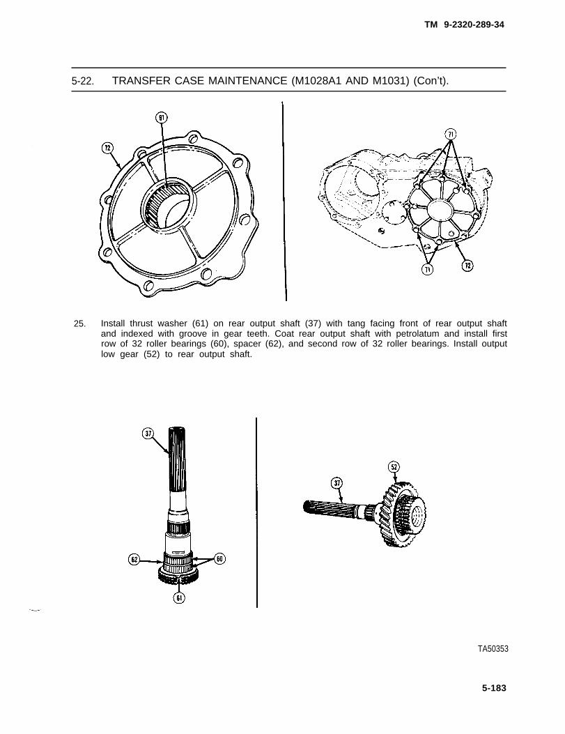
TM 9-2320-289-34
5-22. TRANSFER CASE MAINTENANCE (M1028A1 AND M1031) (Con’t).
25. Install thrust washer (61) on rear output shaft (37) with tang facing front of rear output shaftand indexed with groove in gear teeth. Coat rear output shaft with petrolatum and install firstrow of 32 roller bearings (60), spacer (62), and second row of 32 roller bearings. Install outputlow gear (52) to rear output shaft.
TA50353
5-183

TM 9-2320-289-34
5-22. TRANSFER CASE MAINTENANCE (M1028A1 AND M1031) (Con’t):
26. Install thrust washer (59) with tang facing splined end of rear output shaft (37). Install retainerpin (54) to rear output shaft. Install spacer (55) and index with retainer pin and thrust washertang. Install snapring (53) in rear output shaft groove,
27. Coat pilot bore of rear output shaft (37) with petrolatum and install 15 roller bearings (56),Install spacer (57) and new retainer ring (58), Ensure that retainer ring is fully seated insidepilot bore.
TA50354
5-184

TM 9-2320-289-34
5-22. TRANSFER CASE MAINTENANCE (M1028A1 AND M1031) (Con’t).
28. Install rear output shaft (37) andoutput low gear (52) assembly intransfer case (1) and engage withmain input gear (64).
29. Install new race (42) to retainer (29)if removed. Coat race with petrolatumand install 46 roller bearings (43).
TA50355
5-185

TM 9-2320-289-34
5-22. TRANSFER CASE MAINTENANCE (M1028A1 AND M1031) (Con’t).
30.
31.
Install retainer (29) to transfer case(1) with new gasket, Apply gasketsealing compound to 8 bolts (40) andinstall. Tighten bolts to 30 Ib.-ft.(41 N.m).
Install speedometer drive gear (41)on rear output shaft (37).
32. Install snapring (39) to bearing (38).Install bearing to retainer (29), Installselective snapring (36) on rear outputshaft (37) groove.
33. Use feeler gage to measure end playbetween selective snapring (36) andbearing (38) assembly. End playshould 0.002-0.022 in.(0.05-0.56 mm). If end play is notwithin specifications, removeselective snapring and install one of adifferent thickness.
TA50356
6-186

TM 9-2320-289-34
5-22. TRANSFER CASE MAINTENANCE (M1028A1 AND M1031) (Con’t).
34. Install new bushing to extension (27) if removed. Install new seal (35) to extension. Installextension to retainer (29) with a new gasket. Apply gasket sealing compound to 5 bolts (34).Install bolts and tighten to 30 Ib.-ft. (41 N.m).
35. Install PTO cover (100) with a newgasket (99). Apply gasket sealingcompound to 6 bol ts (101) andinstall.
TA50357
5-187

TM 9-2320-289-34
5-22. TRANSFER CASE MAINTENANCE (M1028A1 AND M1031) (Con’t),
3 6 .
37 .
3 8 .
4 0 .
NOTE
If plugs (45) are steel, RTV sealantshould be applied to them beforeinstalling,
Install 2 plugs (45) to top of transfercase (1). Install ball, spring, newgasket and poppet plug (46), Installball, spring, new gasket, and 4-wheeldrive indicator light switch (17).
If grommet has been removed, heatnew grommet in boiling water to softenand install to shift link (49).
Instal l selector rod (2) throughgrommet to shift link (49) if removed.Install shift link to 4-wheel drive shiftrail (44) and range rail (48) with 2clevis pins (47) and 2 spring clips.
Install front output shaft yoke (50) withnew seal washer, 1 flat washer, andnew locknut (51). Secure yoke in asuitable holding device and tightenlocknut to 150 Ib.-ft. (203 Nom).
TA701859
5-188 Change 2

TM 9-2320-289-34
5-22. TRANSFER CASE MAINTENANCE (M1028A1 AND M1031) (Con’t).
41. Apply RTV sealant to vent (28) and install to retainer (29).
42. Install fill plug (33) and drainplug (32), Tighten drainplug to 40 Ib.-ft. (54 N.m),
e. INSTALLATION
1 . Lightly coat 2 new transfer case adapter seals (9 and 15) with hydraulic fluid and install totransfer case adapter (10).
2 . Install transfer case adapter (10) to transmission with 6 new Iockwashers (12) and bolts (13).Tighten bolts to 30 Ib.-ft. (41 N.m).
3 . Install 2 left transfer case shield bolts (26) and 2 upper transmission mounts (18) totransmission support (19).
4 . Lower transmission and transfer case adapter (10), Remove support from transmission,ensuring that transfer case adapter bolt holes aline with transmission support (19) bolt holes.
TA50359
5-189

TM 9-2320-289-34
5-22. TRANSFER CASE MAINTENANCE (M1028A1 AND M1031) (Con’t).
NOTE
Right bolt (22) must be started first.
5 . Install transfer case adapter (10) to transmission support (19) with 2 spacers (20), lowertransmission mounts (21 ), and bolts (22), Tighten bolts to 40 lb.-ft. (54 N.m).
6 . Install new transfer case adapter gasket (16) to transfer case (1), alining bolt holes.
WARNING
Transfer case (1) is heavy, Provide suitable support and use cautionduring installation. Failure to follow this warning may result in damage totransfer case or serious injury to personnel.
7 . Install two 3/8 in, N.C. bolts, with heads cut off, in transfer case (1) to serve as guide pins.Place transfer case on a suitable jack and raise into position.
5-190

TM 9-2320-289-34
5-22. TRANSFER CASE MAINTENANCE (M1028A1 AND M1031) (Con’t).
CAUTION
Ensure that transfer case (1) is flush against transfer case adapter (10) toavoid damage to transfer case when tightening bolts (11).
8 . Position transfer case (1) against transfer case adapter (10) and in line with transmission outputshaft (8). Apply gasket sealing compound to 8 bolts (11). install 6 new Iockwashers (14) andbolts. Remove 2 guide pins. Install 2 remaining Iockwashers and bolts. Tighten bolts securely.
9 . Connect selector rod (2) to control lever (4) with 1 new wave washer (7), 1 flat washer (6), andnew cotter pin (5). Install 1 flat washer, new wave washer, and pivot bolt (3). Tighten pivot bolt to100 Ib.-ft. (136 N.m).
NOTE
2 left transfer case shield bolts (26) are already in place.
10. Install transfer case shield (23) with 2 right bolts (26), 4 new Iockwashers (25), and nuts (24).
11. Connect connector to 4-wheel drive indicator light switch (17).
TA50361
Change 2 5-191

TM 9-2320-289-34
5-22. TRANSFER CASE MAINTENANCE (M1028A1 AND M1031) (Con’t).
FOLLOW-ON TASKS:
• Install speedometer gear. (See TM 9-2320-289-20)• nstall front and rear propeller shafts. (See TM 9-2320-289-20)• Fill transfer case, (See TM 9-2320-289-20)• Remove jack stands and lower truck.• Connect both battery negative cables. (See TM 9-2320-289-20)• Check operation of transfer case.
5-192 Change 2

TM 9-2320-289-34
CHAPTER 6PROPELLER SHAFTS, AXLES, AND SUSPENSION MAINTENANCE
S e c t i o n I . P R O P E L L E R S H A F T S M A I N T E N A N C E
6-1. CONSTANT VELOCITY JOINT REPAIR.
This task covers: a. Disassembly c. Assemblyb. Cleaning and Inspection
INITIAL SETUP:
Equipment Condition Materials/Parts
● Front propeller shaft removed. • One universal joint repair kit(See TM 9-2320-289-20) • One constant velocity ball kit
Tools/Test Equipment
• Constant velocity
● Dry cleaning solvent(Item 23, Appendix B)
General Safety Instructions
remover/installer, J-23996 ● Dry cleaning solvent is flammable andmust not be used near open flame.Use only in a well-ventilated area.
a . DISASSEMBLY
NOTE
Ensure that front propeller shaftyoke (1) and link yoke (4) aremarked fo r a l inement dur ingassembly.
1 . Make marks (6) on front propellershaft yoke (1) and link yoke (4) forassembly alinement.
2 . if present, remove 2 retainer clips(3). Press out 2 bearing cups (2),and disengage front propeller shaftyoke (1) from link yoke (4) and fromcentering ball. If present, remove 2retainer clips at bearing cups (7).Press out 2 bearing cups (7). Discardall universal joint (8) components.
TA50506
6 - 1

TM 9-2320-289-34
6-1. CONSTANT VELOCITY JOINT REPAIR (Con’t).
3 . Remove seal (9) from centering ball socket (14). Remove washer (10), 3 ball seats (11),washer (12), and spring (13). Discard all components removed from centering ball socket.
4. Place fingers of inner part of constant velocity remover (16) under centering ball (15). Placeouter cylinder (17) of constant velocity remover over inner part and centering ball. Install nut(18) on tool and draw centering ball off stud. Discard centering ball.
TA50507
6-2

TM 9-2320-289-34
6-1. CONSTANT VELOCITY JOINT REPAIR (Con’t).
b. CLEANING AND INSPECTION
WARNING
Dry cleaning solvent P-D-680 is toxic and flammable. Always wearprotective goggles and gloves and use only in a well-ventilated area. Avoidcontact with skin, eyes, and clothes and DO NOT breathe vapors. DO NOTuse near open flame or excessive heat. The solvent’s flash point is100°F-138°F (38°C-59°C). If you become dizzy while using cleaningsolvent, immediately get fresh air and medical help, if solvent contactseyes, immediately wash your eyes with water and get medical aid.
1 . Clean front propeller shaft yoke, link yoke, and end of front propeller shaft (5) with drycleaning solvent.
2 . Inspect ball seat insert bushing in front propeller shaft yoke (1) for wear. Replace frontpropeller shaft yoke if worn.
3. Inspect centering ball stud for damage. Replace front propeller shaft (5) if damaged.
c . ASSEMBLY
CAUTION
Ensure that centering ball (15) is fully seated. Failure to follow this cautionmay result in damage to constant velocity joint,
1. Place new centering ball (15) on stud.Drive new centering ball onto studuntil centering ball seats flush againstshoulder at base of stud. Apply a lightcoat of grease, provided in kit, tocentering ball.
TA50508
6 - 3

TM 9-2320-289-34
6-1. CONSTANT VELOCITY JOINT REPAIR (Con’t).
2. Position new universal joint (8) in frontpropeller shaft yoke (1) and press in2 new bearing cups (7). Install 2 newretainer clips (3) and fully seat inbearing cup grooves.
NOTE
There are 2 springs provided in constant velocity ball kit. Shorter spring(13) is to be used.
3. Lubricate all constant velocity replacement parts with grease provided in kit. In clean centeringball socket (14) in front propeller shaft yoke (1) install in the following order: spring (13), smallO.D. washer (1 2), 3 ball seats (11) with largest opening outward to receive centering ball, andlarge O.D. washer (10).
TA50509
6-4

TM 9-2320-289-34
6-1. CONSTANT VELOCITY JOINT REPAIR (Con’t).
NOTE
Ensure that sealing lip of seal (9) tips inward.
4. Lubricate lip of seal (9) with grease provided in kit and install until flush. Fill cavity with greaseprovided in kit.
5. Using marks (6 ) made dur ingdisassembly, aline front propellershaft yoke (1) and link yoke (4).install front propeller shaft yoke tocentering ball and to link yoke andpress in 2 new bearing cups (2).Install 2 new retainer clips (3) andfully seat in bearing cup grooves.
FOLLOW-ON TASKS:
● Install front propeller shaft. (See TM 9-2320-289-20)
TA50510
6-5/ (6-6 blank)

TM 9-2320-289-34
Section Il. FRONT AND REAR AXLES MAINTENANCE
6-2. FRONT AND REAR AXLES MAINTENANCE INDEX.
ParagraphNumber
6-3.6-4.6-5.6-6.6-7.
6-8.6-9.
6-10.
6-11.6-12.6-13.6-14.
6-15.
6-15.1.6-16.6-17.
6-17.1.
Procedures
Front Axle Assembly Replacement . . . . . . . . . . . . . . . . . . . . . . . . . .Front Axle Shaft Maintenance.. . . . . . . . . . . . . . . . . . . . . . . . . . . . .Front and Rear Axle Differential Replacement (M1009) . . . . . . . . .Front Axle Differential Repair (M1009) . . . . . . . . . . . . . . . . . . . . . . .Front and Rear Axle Drive Pinion and BearingsMaintenance (M1009) . . . . . . . . . . . . . . . . . . . . . . . . . . . . . . . . . . . .Front Axle Differential Maintenance (AH Except M1009) . . . . . . . . .Front Axle Drive Pinion and Bearings Maintenance(All Except M1009) . . . . . . . . . . . . . . . . . . . . . . . . . . . . . . . . . . . . . . .Front and Rear Axle Drive Pinion Oil Seal andPinion Flange Maintenance . . . . . . . . . . . . . . . . . . . . . . . . . . . . . . . .Steering Knuckle and Arm Maintenance (All Except M1009) . . . . .Steering Knuckle, Arm, and Ball Joint Maintenance (M1009) . . . .Rear Axle Assembly Replacement . . . . . . . . . . . . . . . . . . . . . . . . . .Rear Axle Shaft, Outer Seal, Bearing, andBacking Plate Replacement (M1009) . . . . . . . . . . . . . . . . . . . . . . . .Rear Axle Differential Maintenance(All Except M1009, M1028A2, and M1028A3) . . . . . . . . . . . . . . . . .Rear Axle Differential Maintenance (M1028A2and M1028A3) . . . .Rear Axle Differential Repair (M1009) . . . . . . . . . . . . . . . . . . . . . . .Rear Axle Drive Pinion and Bearings Maintenance(All Except M1009, M1028A2, and M1028A3) . . . . . . . . . . . . . . . . .Rear Axle Drive Pinion and Bearings Maintenance(M1028A2 and M1028A3) . . . . . . . . . . . . . . . . . . . . . . . . . . . . . . . .
PageNumber
6-86-126-156-24
6-306-41
6-58
6-686-716-786-83
6-86
6-926-103.0
6-104
6-115
6-122.1
Change 2 6-7

TM 9-2320-289-34
6-3. FRONT AXLE ASSEMBLY REPLACEMENT.
This task covers: a. Removal b. Installation
INITIAL SETUP:
Equipment Condition ToolslTest Equipment
Truck raised and frame supported onjack stands.Front wheels removed.(See TM 9-2320-289-20)Calipers removed and tied out of way.(See TM 9-2320-289-20)Front propeller shaft disconnected from frontaxle differential. (See TM 9-2320-289-20)Connecting rod disconnected from steeringarm. (See TM 9-2320-289-20)Front shock absorbers disconnected from
● Torque wrench
Personnel Required● MOS 63W (2)
General Safety Instructions● Front axle assembly is heavy. Use
extreme caution, provide support, anduse assistance during removal andinstallation.
axle. (See TM 9-2320-289-20)
1. Slide clamp up front axle vent hose (7) and disconnect front axle vent hose from front axledifferential (8).
2 . Place a suitable jack under front axle differential (8).
WARNING
Front axle assembly (10) is heavy, Use extreme caution, provide support,and use assistance during removal, Failure to follow this warning may resultin serious injury to personnel or damage to front axle assembly,
NOTE
. All except M1009 front axle assembly (10) removal is given.
. M1009 front axle assembly (10) is secured to spring assembly (1) using 2“U” bolts (9) on each side.
3 . Remove 6 nuts (4), 2 bolts (5), 8 washers (3), and 3 “U” bolts (9), Lower front axle assembly(10) and remove, Remove 2 spacers (6) from axle housing.
6-8

TM 9-2320-289-34
6-3. FRONT AXLE ASSEMBLY REPLACEMENT (Con’t).
TA50511
6 - 9

TM 9-2320-289-34
6-3. FRONT AXLE ASSEMBLY REPLACEMENT (Con’t).
b. INSTALLATION
WARNING
Front axle assembly (10) is heavy, Use extreme caution, provide support,and use assistance during installation. Failure to follow this warning mayresult In serious injury to personnel or damage to front axle assembly.
●
●
NOTE
All except M1009 front axle assembly (10) installation Is given.
M1009 front axle assembly (10) is secured to spring assembly (1) using2 “U” bolts (9) on each side.
1. Pisutuib fribt axle assembly (10) on suitable jack and raise into position. Install 2 spacers (6)on axle housing, alining holes in spacers with holes in axle housing and spring assembly (1)center bolts. Loosely install 3 “U” bolts (9) with 8 washers (3), 6 nuts (4), and 2 bolts (5).Install all nuts and bolts to uniform engagement on “U” bolts to retain and position anchor plate(2) .
All nuts (4) and bolts (5) mustassemblies (1) seat properly.
NOTE
be tightened evanly to ensure that spring
2 . Tighten all nuts (4) and bolts (5) in diagonal sequence to 25 Ib.-ft. (34 N.m). Using samediagonal sequence, fully tighten all nuts and bolts to 150 Ib.-ft, (203 N.m).
3 . Remove jack from front axle differential (8).
4 . Connect front axle vent hose (7) to front axle differential (8) and tighten clamp.
6-10

TM 9-2320-289-34
6-3. FRONT AXLE ASSEMBLY REPLACEMENT (Con’t).
FOLLOW-ON TASKS:
● Connect front shock absorbers to axle. (See TM 9-2320-289-20)● Connect connecting rod to steering arm. (See TM 9-2320-289-20)● Connect front propeller shaft to front axle differential. (See TM 9-2320-289-20)● Install calipers. (See TM 9-2320-289-20)● Install front wheels, (See TM 9-2320-289-20)● Remove jack stands and lower truck.● Road test truck and check torque of “U” bolt fasteners.
TA50512
6-11

TM 9-2320-289-34
6-4. FRONT AXLE SHAFT MAINTENANCE.
This task covers: a. Removal c . Installationb. Cleaning and Inspection
INITIAL SETUP:
Equipment Condition Materials/Parts
● Front axle spindle removed. • One universal joint repair kit(See TM 9-2320-289-20) • One axle shaft seal
• One spindle seal● Dry cleaning solvent
(Item 23, Appendix B)• Grease (Item 36, Appendix B)
General Safety Instructions
● Dry cleaning solvent is flammable and must not be used near open flame. Use only in awell-ventilated area.
a. REMOVAL
1 . Remove front axle shaft assembly (1 and 7).
2 . If not already removed, remove spindle seal (6), axle shaft seal (5), and bronze spacer (8)from outer axle shaft (7). Discard seals.
3 . Remove deflector (4).
4 . Place front axle shaft assembly (1 and 7) over wooden blocks. Remove 4 retainer clips (10).Press out 4 bearing cups (2) and remove universal joint (3), Separate outer axle shaft (7) frominner axle shaft (1), Discard retainer clips, bearing cups (2), and universal joint (3).
b . CLEANING AND INSPECTION
WARNING
Dry cleaning solvent P-D-680 is toxic and flammable. Always wearprotective goggles and gloves and use only in a well-ventilated area. Avoidcontact with skin, eyes, and clothes and DO NOT breathe vapors. DO NOTuse near open flame or excessive heat. The solvent’s flash point is100°F-138°F (38°C-59°C). If you become dizzy while using cleaningsolvent, immediately get fresh air and medical help. If solvent contactseyes, immediately wash your eyes with water and get medical aid.
1. Clean inner and outer axle shafts with dry cleaning solvent.
2 . Inspect inner and outer axle shafts for cracks, bends, or damaged splines. Replace if cracked,bent, or if splines are damaged.
c. INSTALLATION
1. Position new universal joint (3) in outer axle shaft (7) yoke.
6-12

TM 9-2320-289-34
6-4. FRONT AXLE SHAFT MAINTENANCE (Con’t).
CAUTION
● Ensure that seal (9) and washer(12) are properly positionedand that needle bearings (11)are properly alined in bearingcups (2),
● Ensure that bearing cups (2)are alined with universal joint(3) trunnion. Failure to followthis caution may resu l t i ndamage to universal joint andbearing cups.
2 . Position 2 bearing cups (2) at outsideof outer axle shaft (7) yoke and pressin bearing cups far enough to install 2retainer clips (10).
TA50513
6-13

TM 9-2320-289-34
6-4. FRONT AXLE SHAFT MAINTENANCE (Con’t).
3 .
4 .
5 .
6 .
Repeat step 2 to install other 2 bearing cups (2) into inner axle shaft (1) yoke.
NOTE
Ensure that bronze spacer (8) Is fully seated against shoulder of outer axleshaft (7).
Install deflector (4) and bronze spacer (8) to outer axle shaft (7). Install new axle shaft seal (5)on outer axle shaft with lip facing outward. Pack area around thrust face area of outer axleshaft and axle shaft seal with grease.
Install new spindle seal (6) on outer axle shaft (7) with lip facing inward.
Install front axle shaft assembly (1 and 7),
FOLLOW-ON TASKS:
● Install front axle spindle, (See TM 9-2320-289-20)• Check front axle differential lubricating oil level. (See LO 9-2320-289-12)
TA50514
6-14

TM 9-2320-289-34
6-5. FRONT AND REAR AXLE DIFFERENTIAL REPLACEMENT (M1009).
This task covers: a. Removal c. Installationb. Cleaning and Inspection
INITIAL SETUP:
Equipment Condition Materials/Parts
● Front or rear axle shafts removed. • One differential cover gasket(See paragraph 6-4 or 6-14) • Shim sets
• Steering tie-rod removed (if replacing front ● Prussian blue dyeaxle differential). (See TM 9-2320-289-20) (Item 24, Appendix B)
• Gear lubricating oil(Item 44, Appendix B)
Tools/Test Equipment Personnel Required
● Bearing preload gage and strap, J-22779 ● MOS 63W (2)● Dial indicator● Micrometer Manual References● Torque wrench ● TM 9-214
General Safety Instructions
● Dry cleaning solvent is flammable and must not be used near open flame. Use only in awell-ventilated area.
a. REMOVAL
1. If working on front axle differential,place a suitable container underhousing. Remove 10 bolts (1) andcover (2). Allow all lubricating oil todrain. Remove cover gasket anddiscard.
TA50516
6-15

TM 9-2320-289-34
6-5. FRONT AND REAR AXLE DIFFERENTIAL REPLACEMENT (M1009) (Con’t).
2. Mark 2 bearing caps (3) and housingfor installation alinement. Remove 4bolts (4) and bearing caps.
●
●
NOTE
Front axle differential has shims (5) and spacers at side bearingassemblies. Rear axle differential has only shims.
When removing differential case (7) assembly from housing, bearingcups (6), shims (5), and spacers may fall out. Ensure that bearingC U P S, shims, and spacers are tagged, indicating from which side theywere removed.
3. Work differential case (7) assemblyloose. Remove differential caseassembly, bearing cups (6), shims(5), and spacers if present.
TA50516
6-16

TM 9-2320-289-34
6-5. FRONT AND REAR AXLE DIFFERENTIAL REPLACEMENT (M1009) (Con’t).
b. CLEANING AND INSPECTION
WARNING
1.
2 .
3 .
4 .
5 .
Dry cleaning solvent P-D-680 is toxic and flammable. Always wearprotective goggles and gloves and use only in a well-ventilated area. Avoidcontact with skin, eyes, and clothes and DO NOT breathe vapors. DO NOTuse near open flame or excessive heat. The solvent’s flash point is100°F-138°F (38°C-590C). If you become dizzy while using cleaningsolvent, immediately get fresh air and medical help. If solvent contactseyes, immediately wash your eyes with water and get medical aid.
Clean differential cover and magnet, interior of housing, bearing cups, and shims with drycleaning solvent. Clean all gasket material from differential cover and housing.
Inspect shims and spacers for damage. Replace if damaged.
Inspect condition of differential side bearings and bearing cups in accordance with TM 9-214.Inspect cup seats in housing and bearing caps to ensure that they are free of nicks, burrs, andforeign material. Remove any nicks, burrs, or foreign material found.
If present, remove excess casting material near machined surfaces to provide for installationof shims and bearing preload gage. Remove all traces of filing dust.
NOTE
● Ensure that position of axle shaft inner seals is noted for installation.
● There are no axle shaft seals on rear axle assembly.
Inspect 2 axle shaft inner seals in housing side bores. Remove and discard if damaged.
6-17

TM 9-2320-289-34
6-5. FRONT AND REAR AXLE DIFFERENTIAL REPLACEMENT (M1009) (Con’t).
c. lNSTALLATION
1. If removed, install 2 new axle shaft inner seals in housing side bores,
2. Install 2 bearing cups (6) as tagged, over side bearings (10), Install differential case (7)assembly inside housing.
3. Install bearing strap tool (8) over left side bearing cup (6) with 2 bolts.
4. With ring gear (12) tight against drive pinion (9), insert bearing preload gage (13) between leftbearing cup (6) and housing.
5. While moving bearing preload gage (13), turn adjusting nut clockwise until a noticeable drag isfelt. Tighten Iockbolt on side of tool,
6. Between right bearing cup (6) and housing, install spacer if removed, and a shim (5) thinnerthan what was originally installed. Install a feeler gage (11) between shim and housing. Feelergage must be of sufficient thickness to produce a slight drag when moved between shim andhousing,
TA50517
6-18

TM 9-2320-289-34
6-5. FRONT AND REAR AXLE DIFFERENTIAL REPLACEMENT (M1009) (Con’t).
7 . Remove bearing preload gage (13), spacer if installed, shim (5), and feeler gage (11).
8 . Measure thickness of bearing preload gage (13) in 3 places and average these readings.Record the result.
9 . Measure combined thickness of spacer if present, shim (5), and feeler gage (11).
10 . Using example given in Table 6-1, determine proper thickness of each shim pack,
Table 6-1. Determining Side Bearing Shim Requirements
OPPOSITE SIDE
inches millimeters inches millimeters
0.250 In. 6.350 mm Thickness of bearing Combined total of 0.265 In. 6.731 mmpreload tool required spacer, service shim,to force ring gear Into and feeler gage.contact with drive pln-Ion.
TO MAINTAIN PROPER BACKLASH (0 .005 In. --0.010 In. -0.254 mm 0.008 in. ) (0.127 mm - 0.2032 mm), ring gear is
moved away from pinion by subtracting 0.010 in. + 0.010 in.0.240 in.
+ 0.254 mm6.096 mm (O .254 mm) shims from ring gear side and adding 0.275 in. 6.985 mm
0.010 in. (0.254 mm) shims to the opposite side.1
+0.004 in. TO OBTAIN PROPER PRELOAD on side bearings,+ 0.102 mm add 0.004 in. (0. 102 mm) to each side. + 0.004 in. +0.102 mm
0.244 in. 6.198 mm Shim dimension re- Shim dimension re- 0.279 in. 7.087 mmquired for ring gear quired for oppositeside, side.
RING GEAR SIDE
11. If present, install 2 spacers as tagged, between bearing cups (6) and housing.
NOTE
● Production preloading of the differential side bearings (10) isaccomplished by use of cast iron preload shims. These cannot bereused when rebuilding the housing as they may break when tappedinto place. Service shims may be reused if not damaged.
• Chamfered side of shim (5) should face outward. Shim should havesufficient chamfer or lead around outside diameter to allow for easyinstallation. Additional chamfer on shim should be filed or ground asrequired.
6-19

TM 9-2320-289-34
6-5. FRONT AND REAR AXLE DIFFERENTIAL REPLACEMENT (M1009) (Con’t).
NOTE
If shim (5) is difficult to install,differential case (7) assembly maybe partially removed, then shimand differential case assembly slidinto position at same time.
12. Install left shim (5) first, betweenspacer, if present, and housing.Install right shim. Using soft-facedhammer, tap shims into place whilerotating differential case (7)assembly.
13. Remove 2 bolts and bearing strap tool (8).
TA50518
6-20

TM 9-2320-289-34
6-5. FRONT AND REAR AXLE DIFFERENTIAL REPLACEMENT (M1009) (Con’t).
140
15.
16.
Install 2 bearing caps (3) in their original positions and install 4 bolts (4). Tighten bolts to55 Ib.-ft. (75 N.m).
NOTE
Differential side bearings (10) are now properly preloaded. If anyadjustments are required in later procedures, ensure that preloadestablished in step 12 remains the same. If backlash is changed in latersteps, the total thickness of 2 shim packs does NOT change.
Mount dial indicator (14) on housing with indicator button perpendicular to tooth angle and inline with ring gear (12) rotation. Check backlash between ring gear and drive pinion. Backlashshould be within range of 0.005-0.008 in. (0.13-0.20 mm). Check backlash at 4 differentequally spaced positions around ring gear. Variation in the 4 readings should not exceed0.001 in. (0.025 mm).
If variation in backlash readings exceeds 0.002 in. (0.051 mm), reposition dial indicator (14)on housing so that indicator button contacts back of ring gear (12) and measure ring gear andhousing runout. Gear runout should not exceed 0.003 in. (0.076 mm). If runout exceeds thislimit, inspect ring gear and housing for deformation or foreign matter between housing and ringgear.
TA50519
6-21

TM 9-2320-289-34
6-5. FRONT AND REAR AXLE DIFFERENTIAL REPLACEMENT (M1009) (Con’t).
17. If backlash is not within limits, decrease shim thickness on one side and increase shimthickness on other side by an equal amount:
(a) If backlash exceeds .008 in. (0.20 mm), increase shim thickness on ring gear (12) sideand decrease thickness on opposite side by an equal amount.
(b) If backlash is less than 0.005 in. (0.13 mm), decrease shim thickness on ring gear (12)side and increase thickness on opposite side by an equal amount.
NOTE
If drive pinion and ring gear (12) were replaced, perform steps 20-23 tocheck for proper gear tooth contact pattern.
18. Wipe any lubricant from housing and clean each tooth of ring gear (12).
19. Apply prussian blue dye sparingly to all ring gear (12) teeth using medium stiff brush, Area oftooth contact should be clearly visible after load is applied to gears.
NOTE
Excessive turning of ring gear (12) is not recommended. Ring gear shouldonly be turned enough to provide tooth contact pattern.
20. Apply load until it takes a torque of 40-50 Ib.-ft. (54-68 N.m) to turn drive pinion. Turncompanion flange so that ring gear (12) turns 1 full revolution, then reverse so that ring gearturns 1 full revolution in opposite direction.
TA50520
6-22

TM 9-2320-289-34
6-5. FRONT AND REAR AXLE DIFFERENTIAL REPLACEMENT (M1009) (Con’t).
21. Contact pattern should be centrally located up and down on the face of the ring gear (12)teeth. Compare tooth contact pattern on ring gear with examples shown and makeadjustments as indicated.
2 2 . If working on front axle differential,install new cover gasket and cover(2) with 10 bolts (1). Tighten bolts to35 Ib.-ft. (47 N.m).
FOLLOW-ON TASKS:
● Install steering tie-rod if removed. (See TM 9-2320-289-20)● Install front or rear axle shafts, (See paragraph 6-4 or 6-14)● Fill front or rear axle differential with lubricating oil. (See LO 9-2320-289-12)
TA50521
6-23

TM 9-2320-289-34
6-6. FRONT AXLE DIFFERENTIAL REPAIR (M1009).
This task covers: a. Disassembly c. Assemblyb. Cleaning and Inspection
INITIAL SETUP:
Equipment condition Materials/Parts
● Front axle differential removed. ● Dry cleaning solvent(See paragraph 6-5) (Item 23, Appendix B)
● Gear lubricating oil(Item 44, Appendix B)
● Wiping rags (Item 53, Appendix B)
Tools/Test Equipment
● Puller kit● Torque wrench
Manual References
● TM 9-214
General Safety Instructions
● Dry cleaning solvent is flammable and must not be used near open flame. Use only in awell-ventilated area.
● Compressed air used for cleaning purposes should never exceed 30 psi (207 kPa).
a . DISASSEMBLY
1 . Place differential case (1) assemblyin vise.
2 . Remove 2 side bearings (2) and tagfor assembly.
TA50522
6-24

TM 9-2320-289-34
6-6. FRONT AXLE DIFFERENTIAL REPAIR (M1009) (Con’t).
NOTE
Shop rags placed around vise will help protect ring gear (4) teeth fromdamage should ring gear fali during disassembly.
3 . Scribe a line on differential case (1)assembly and ring gear (4) to ensureassembly in same position. Remove10 bolts (3). Using a soft-facedhammer, tap ring gear loose fromdifferential case assembly. Removedifferential case assembly from viseand remove ring gear.
4 . Drive out Iockpin (6) and removepinion shaft (5).
6-26

TM 9-2320-289-34
6-6. FRONT AXLE DIFFERENTIAL REPAIR (M1009) (Con’t).
NOTE
Ensure that pinion gears (7), side gears (8), and thrust washers (9) aremarked for assembly,
5. Rotate 2 side gears (8). Remove 2pinion gears (7) and thrust washers(9). Remove 2 side gears and thrustwashers,
b. CLEANING AND INSPECTION
WARNING
● Dry cleaning solvent P-D-680 is toxic and flammable. Always wearprotective goggles and gloves and use only in a well-ventilated area.Avoid contact with skin, eyes, and clothes and DO NOT breathe vapors.DO NOT use near open flame or excessive heat. The solvent’s flashpoint is 100°F-138°F (38°C-59°C). If you become dizzy while usingcleaning solvent, immediately get fresh air and medical help, if solventcontacts eyes, immediately wash your eyes with water and get medicalaid.
● Compressed air used for cleaning purposes should never exceed 30 psi(207 kPa). Us. only l ffective chip guarding and personnel protectiveequipment (goggles/shield, gloves, etc.). Failure to follow this warningmay result in serious injury to personnel.
1. Clean all removed components with dry cleaning solvent and dry with compressed air.
2. Clean and inspect differential side bearings in accordance with TM 9-214. If one side bearing isdamaged, replace both side bearings.
TA50624
6-26

TM 9-2320-289-34
6-6. FRONT AXLE DIFFERENTIAL REPAIR (M1009) (Con’t).
3. Inspect differential case for cracks, scoring, or signs of damage to machined surfaces.Remove any nicks or burrs found. Replace differential case if cracked or damaged.
NOTE
If ring gear is damaged, ring gear bolts and drive pinion must also bereplaced. (See paragraph 6-7)
4. Inspect ring gear for damage. Replace if damaged.
5. Inspect thrust washers,damaged, replace both
pinion gears, and side gears for damage. If a pinion or side gear isas a set.
c. ASSEMBLY
NOTE
1 .
2 .
3 .
4 .
Ensure that all componentsassembled.
Place differential case (1) in vise.
Install 2 side gears (8) and thrust
are lubricated with lubricating oil as they are
washers (9) inside differential case (1). If side gears andthrust washers are original, install as marked.
NOTE
Ensure that holes In pinion gears (7) are alined with holes in differentialcase (1) assembly.
Assemble 2 pinion gears (7) andthrust washers (9) and roll intoposition inside differential case (1)assembly. If pinion gears and thrustwashers are original, install asmarked.
Install pinion shaft (5) and retain withIockpin (6).
TA50525
6-27

TM 9-2320-289-34
6-6. FRONT AXLE DIFFERENTIAL REPAIR (M1009) (Con’t).
NOTE
Shop rags placed around vise will help protect ring gear (4) teeth mfromdt ri should ring gear fall during assembly.
5 . Remove differential case (1)assembly from vise. Assemble ringgear (4) to differential case assemblyalining marks made duringdisassembly, if original ring gear isused. Place differential caseassembly in vise.
6. Install 10 bolts (3) and tightenalternately to 80 lb.-ft. (108 N.m).
NOTE
Side bearings (2) should rotatefreely once installed.
7. Install 2 side bearings (2) as tagged.
TA50526
6-28

TM 9-2320-289-34
6-6. FRONT AXLE DIFFERENTIAL REPAIR (M1009) (Con’t).
FOLLOW-ON TASKS:
● Install front axle differential. (See paragraph 6-5)
6-29

TM 9-2320-289-34
6-7. FRONT AND REAR AXLE DRIVE PINION AND BEARINGS MAINTENANCE(M1009).
This task covers: a . R e m o v a l c. Installationb. Cleaning and Inspection
INITIAL SETUP:
Equiprnent Condition Materials/Parts
● Front or rear axle differential removed. ● One flange nut(See paragraph 6-5) ● One pinion oil seal
● Front or rear propeller shaft disconnected ● One spacerfrom pinion flange. (See TM 9-2320-289-20) ● Dry cleaning solvent
(Item 23, Appendix B)● Molybdenum grease
(Item 37, Appendix B)• Gear lubricating oil
(Item 44, Appendix B)
Tools/Test Equipment
● Pinion setting gage, J-21777-500● Flange holder and remover● Micrometer● Puller kit● Torque wrench
Manual References
● TM 9-214
General Safety Instructions
● Dry cleaning solvent is flammable and must not be used near open flame. Use Only in awell-ventilated area.
• Compressed air used for cleaning purposes should never exceed 30 psi (207 kPa).
a R E M O V A L
1 . A t f l a n g e ( 1 ) , measure torquerequired to rotate drive pinion andrecord for later reference. If there isno p re load read ing , check fo rlooseness of pinion assembly bypushing and pul l ing on f lange.Looseness indicates need for bearingreplacement.
TA50527
6-30

TM 9-2320-289-34
6-7. FRONT AND REAR AXLE DRIVE PINION AND BEARINGS MAINTENANCE(M1009) (Con’t).
NOTE
Flange nut (2) should be saved for use during drive pinion (3) installation,When drive pinion is fully seated and ready to receive final torque, a newflange nut must be used,
2 . Using flange holder (5), remove flange nut (2) and washer from flange (1).
3. Install flange remover bolt into small outside diameter end of flange remover (6). Turn flangeremover 1/8 turn to a locked position. Turn flange remover while holding flange holder (5)stationary, Remove flange (1).
4 . Install flange nut (2), removed in step 2, halfway on drive pinion (3) threads. Tap on nut withsoft-faced hammer to loosen drive pinion, Remove flange nut from drive pinion. Remove drivepinion from housing (4).
TA60628
6-31

TM 9-2320-289-34
6-7. FRONT AND REAR AXLE DRIVE PINION AND BEARINGS MAINTENANCE(M1009) (Con’t).
5 . Remove oil seal (11 ) and front bearing (10). Remove spacer (8) from drive pinion (3) shaft,Discard oil seal and spacer.
CAUTION
Care should be taken when removing bearing cups (7 and 9). Oppositeends of bearing cups should be alternately tapped to avoid their becomingcocked in housing (4). Failure to follow this caution may result in damageto bearing cups and to housing bore.
6 . Remove front bearing cup (9) and rear bearing cup (7) from housing (4).
7. Using puller kit and press, removerear ‘bearing (12)(3) shaft.
8. Remove shim(s)rear bearing (12)pinion (3).
from drive pinion
located betweenand head of drive
6-32

TM 9-2320-289-34
6-7. FRONT AND REAR AXLE DRIVE PINION AND BEARINGS MAINTENANCE(M1009) (Con’t).
b . CLEANING AND INSPECTION
WARNING
● Dry cleaning solvent P-D-680 is toxic and flammable, Always wearprotective goggles and gloves and use only in a well-ventilated area.Avoid contact with skin, eyes, and clothes and DO NOT breathe vapors.DO NOT use near open flame or excessive heat. The solvent’s flashpoint is 100°F-138°F (38°C-59°C). If you become dizzy while usingcleaning solvent, immediately get fresh air and medical help. If solventcontacts eyes, immediately wash your eyes with water and get medicalaid.
• Compressed air used for cleaning purposes should never exceed 30 psi(207 kPa). Use only effective chip guarding and personnel protectiveequipment (goggles/shield, gloves, etc.). Failure to follow this warningmay result in serious injury to personnel.
1 . Clean and inspect front and rear bearing assemblies in accordance with TM 9-214.
2 . Clean drive pinion, shim(s), and flange with dry cleaning solvent and dry with compressed air.
3 . Clean bearing bores in housing with dry cleaning solvent to ensure that they are free of dirt orother contamination, Remove any nicks or burrs found.
4 . Clean pinion setting gage tool parts with dry cleaning solvent to ensure that pinion depthmeasurements will be accurate.
NOTE
If drive pinion is replaced, differential ring gear and ring gear bolts mustalso be replaced. (See paragraph 6-6 or 6-16)
5. Inspect drive pinion, flange, and shim(s) for damage. Replace if damaged. If shim (s) isundamaged, measure and save for installation.
6-33

TM 9-2320-289-34
6-7. FRONT AND REAR AXLE DRIVE PINION AND BEARINGS MAINTENANCE(M1009) (Con’t).
c . INSTALLATION
NOTE
• Ensure that all components are lubricated with lubricating oil as theyare installed.
● If original drive pinion and rear bearing (12) are being reused, performsteps 1 and 11 through 17. Original shim thickness is used,
● If a new drive pinion or rear bearing (12) are being installed, performsteps 1-17.
1 . Install front bearing cup (9) and rear bearing cup (7) in housing (4) with wider, open endsfacing outward. Check both bores to ensure that bearing cups are fully seated.
TA50530
6-34

TM 9-2320-289-34
6-7. FRONT AND REAR AXLE DRIVE PINION AND BEARINGS MAINTENANCE(M1009) (Con’t).
2 . Install front bearing (10) in bearing cup (9), and rear bearing (12) in bearing cup (7), withcloverleaf gage plate (13) and rear pilot washer (14) mounted on preload stud (15) andinstalled in bearing bore in housing (4).
3 . Install front pilot washer (17) and hex nut (16) until snug, and rotate front and rear bearings (10and 12) to ensure that they are properly seated, Hold preload stud (15) stationary and tightenhex nut until it takes 20 lb.-in. (2 N.m) to rotate front and rear bearing assembly,
TA50531
6-35

TM 9-2320-289-34
6-7. FRONT AND REAR AXLE DRIVE PINION AND BEARINGS MAINTENANCE(M1009) (Con’t).
4. Mount 2 side bearing discs (18) on ends of arbor (19) using step of disc that fits bores ofhousing (4). Place arbor and plunger in housing, Ensure that side bearing discs are properlyseated in bores. Install 2 bearing caps over side bearing discs and tighten 4 bearing cap boltsuntil snug.
5. Place dial indicator (20) on mounting post of arbor. Contact button should rest on top surfaceof plunger. “O” the dial indicator with probe on high point of gaging surface.
6. Rotate gage plate (13) until plunger rests directly upon 8 1/2 in. button. Rock plunger rod slowlyback and forth across button until dial indicator (20) reads greatest deflection. Set dialindicator to “O. ”
7. Ensure that all tools are properly and securely installed inside housing (4).
NOTE
It is important to use dial indicator (20) correctly when determining piniondepth requirement. Number indicated by indicator needle should berecorded. - DO NOT record amount of needle travel.
8. Repeat rocking action of plunger several times to verify dial indicator (20)setting is obtained, swing plunger off gaging plate button. Dial indicator willdrive pinion shim thickness for “nominal” or “O“ pinion. Record reading.
setting, Once finalnow show required
TA50532
6-36

TM 9-2320-289-34
6-7. FRONT AND REAR AXLE DRIVE PINION AND BEARINGS MAINTENANCE(M1009) (Con’t).
9 . Remove dial indicator (20), 2 bearing caps, depth gaging tools, and front and rear bearings(1 O and 12) from housing (4).
10. Check rear face of drive pinion, or painted marking on drive pinion shaftpinion code number. Calculate drive pinion shim thickness to be used.
Table 6-2. Determining Drive Pinion Shim Requirements
being installed, for
(a) If drive pinion has no plus (+) or minus (-), use exact shim thickness as recorded instep 8.
(b) If drive pinion is stamped or painted with a plus (+) number, add that many thousandths tothickness recorded in step 8.
EXAMPLE:
(c) If drive pinion isthousandths from
EXAMPLE:
If reading from step 8 was 0.019 in. (0.483 mm) anddrive pinion was stamped “+2,” correct shimthickness is:
0.019 in. + 0.002 in. = 0.021 in.
(0.483 mm + 0.057 mm = 0.534 mm)
stamped or painted with a minus (-) number, subtract that manythickness recorded in step 9.
If reading from step 8 was 0,031 in, (0.787 mm),and drive pinion was stamped “-3, ” correct shimthickness is:
0.031 in. -0.003 in. = 0.028 in.
(0.787 mm -0.076 mm = 0.711 mm)
6-37

TM 9-2320-289-34
6-7. FRONT AND REAR AXLE DRIVE PINION AND BEARINGS MAINTENANCE(M1009) (Con’t).
11. Place shim of correct thickness asdetermined in step 10, or originalshim if drive pinion (3) was notreplaced, on dr ive pin ion shaftagainst head. Install rear bearing (12)on drive pinion shaft.
12. Install front bearing (10) in bearing cup (9) in housing (4) bore.
13. Coat lips of new pinion oil seal (11) with molybdenum grease and install squarely into housing(4) bore until flush with housing.
TA50533
6-38

TM 9-2320-289-34
6-7. FRONT AND REAR AXLE DRIVE PINION AND BEARINGS MAINTENANCE(M1009) (Con’t).
14. Install new spacer (8) on drive pinion (3) shaft, Place drive pinion into position. Mount asuitably sized thick washer over threaded stem of drive pinion and install original flange nut (2).Tighten flange nut enough to draw drive pinion through front bearing (10) so that threads areexposed when flange is placed into position. Remove flange nut and washer. Discard flangenut.
15. Install flange (1), original washer(21 ), and new flange nut (2), Usingflange holder (5), tighten flange nutuntil all end play is removed fromdrive pinion (3). Remove flangeholder. At this point, bearing preloadspecifications are being neared.
6-39

TM 9-2320-289-34
6-7. FRONT AND REAR AXLE DRIVE PINION AND BEARINGS MAINTENANCE(M1009) (Con’t).
16 .
1 7 .
CAUTION
Tightening flange nut (2) as little as 1/8 turn can add up to 5 additionalpound-inches of drag. Flange nut should be tightened only a little at atime. Exceeding torque specifications may compress spacer (8) on drivepinion shaft too far and require replacement of spacer.
Measure rotating torque, it should be 20-25 lb.-in. (2-3 N.m) on new bearings, or10–1 5 lb.-in, (1-2 N.m) on reused bearings. If rotating torque specifications have not beenreached, tighten flange nut (2). Check rotating torque after each slight amount of tightening.
Rotate drive pinion (3) several times to ensure that bearings are seated. Check preload dragagain. If drag has been reduced, reset preload to specifications.
FOLLOW-ON TASKS:
• Connect front or rear propeller shaft to pinion flange. (See TM 9-2320-289-20)● Install front or rear axle differential. (See paragraph 6-5)
TA50535
6-40

TM 9-2320-289-34
6-8. FRONT AXLE DIFFERENTIAL MAINTENANCE (ALL EXCEPT M1009).
This task covers: a. Removal d. Assemblyb. Disassembly e. Preload and Adjustmentc. Cleaning and Inspection f. Installation
INITIAL SETUP:
Equipment Condition Materials/Parts
●
●
●
Front axle assembly removed and mounted •on stand. (See paragraph 6-3) ●
Steering tie-rod removed.(See TM 9-2320-289-20) ●
Front axle shafts removed,(See paragraph 6-4) ●
●
●
One differential cover gasketDry cleaning solvent(Item 23, Appendix B)Prussian blue dye(Item 24, Appendix B)Gear lubricating oil(Item 44, Appendix B)Wiping rags (Item 53, Appendix B)Masking tape (Item 68, Appendix B)
Tools/Test Equipment Manual References
• Clutch compressor, J-34502 ● TM 9-214● Axle housing spreader● Dial indicator● Puller kit● Torque wrench
General Safety Instructions
● Dry cleaning solvent is flammable and must not be used near open flame. Use only in awell-ventilated area,
● Compressed air used for cleaning purposes should never exceed 30 psi (207 kPa).
a . R E M O V A L
1 . Place a suitable container underhousing. Remove 10 bolts (1) anddifferential cover (2) and allow alllubricating oil to drain. Removedifferential cover gasket-and discard.
TA50536
6-41

TM 9-2320-289-34
6-8. FRONT AXLE DIFFERENTIAL MAINTENANCE (ALL EXCEPT M1009) (Con’t),
2. Mark 2 side bearing caps (3) andhousing for installation alinement.Remove 4 bolts (4) and 2 sidebearing caps.
3. Position axle housing spreader (5)with tool dowels fitted into recesses inhousing. Install dial indicator (24)from dowel pin bar to dowel pin bar.Ensure that dial indicator ispreloaded. Set dial indicator to “0,”
CAUTION
Housing should not be spreadmore than 0.015 in. (0.381 mm).Failure to follow this caution maycause h o u s i n g t o becomedamaged and permanentlydistorted.
4 . S p r e a d h o u s i n g t o 0.015 in.(0.381 mm). Remove dial indicator(24) .
TA50537
6-42

TM 9-2320-289-34
6-8. FRONT AXLE DIFFERENTIAL MAINTENANCE (ALL EXCEPT M1009) (Con’t).
5. Remove differential case (7)assembly from housing. Remove andtag 2 side bearing cups (6) forinstallation. Relieve tension on axlehousing spreader (5) and removefrom housing.
b. DISASSEMBLY
NOTE
●
●
●
M1008 and M1010 front axledifferentials have thrustwashers at side gears. M1028,M1028A1, and M1031 haveclutch packs.
If disassembling M1008 orM1010 front axle differential,perform steps 1-6.
If disassemblingM1028A1, or M1031differential, performand steps 7-10.
steps 1-5front axle
1. Place differential case (7) assemblyin vise,
2. Remove 2 side bearings (9) and sidebearing shims (10). Tag sidebearings and side bearing shims forinstallation.
TA50538
6 - 4 3

TM 9-2320-289-34
6-8. FRONT AXLE DIFFERENTIAL MAINTENANCE (ALL EXCEPT M1009) (Con’t).
NOTE
Axle shaft (14) serves as a tool tohelp aline pinion gears (15) andside gears (16).
3 . Remove differential case (7)assembly from vise. Place axle shaft(14) in vise with no more than 3 in.(76 mm) above top of vise. Placedifferential case assembly on axleshaft.
NOTE
Shop rags placed around vise will help protect ring gear (11) teeth fromdamage should ring gear fall during disassembly.
4 . Remove Iockpin (13). Remove 12 ringgear bolts (8). Tap on ring gear (11)with a soft-faced hammer to separatering gear from differential case (7)assembly. Remove differential caseassembly from axle shaft and removering gear.
5 . Place differential case (7) assemblyon axle shaft in vise. Remove pinionshaft (12).
TA50539
6-44

TM 9-2320-289-34
6-8. FRONT AXLE DIFFERENTIAL MAINTENANCE (ALL EXCEPT M1009) (Con’t).
NOTE
Perform step 6 only if working on M1008 or M1010.
6. Rotate side gears (16) until piniongears (15) turn to opening indifferential case (7) assembly.Remove 2 pinion gears and thrustwashers (17) behind gears. Remove2 side gears and thrust washers.
7 .
8 .
NOTE
Perform steps 7-10 only if working on M1028, M1028A1, or M1031.
Install clutch compressor (18) andremove tension from clutch packs.Remove 2 thrust washers (17) frombehind pinion gears (1 5). Rotatedifferential case (7) assembly andremove 2 pinion gears.
Hold top clutch pack and side gear(16) in place and remove clutchcompressor (18).
TA50540
6-45

TM 9-2320-289-34
6-8. FRONT AXLE DIFFERENTIAL MAINTENANCE (ALL EXCEPT M1009) (Con’t).
NOTE
Ensure that clutch packs are kept intact as they are removed.
9 . Remove 2 clutch packs and side gears (16).
1 0 . Remove 2 retainer clips (20) from each clutch pack and separate 4 clutch plates (19) and 4discs (21), Remove dished spacer (22) from each side gear (16).
c . CLEANING AND INSPECTION
WARNING
Dry cleaning solvent P-D-680 is toxic and flammable. Always wearprotective goggles and gloves and use only In a well-ventilated area. Avoidcontact with skin, eyes, and clothes and DO NOT breathe vapors. DO NOTuse near open flame or excessive heat. The solvent’s flash point is100°F-138°F (38°C-59°C). If you become dizzy while using cleaningsolvent, immediately get fresh air and medical help. If solvent contactseyes, immediately wash your eyes with water and get medical aid.
TA50541
6-46

TM 9-2320-289-34
6-8. FRONT AXLE DIFFERENTIAL MAINTENANCE (ALL EXCEPT M1009) (Con’t).
W A R N I N G
Compressed air used for cleaning purposes should never exceed 30 psi(207 kPa). Use only effective chip guarding and personnel protectiveequipment (goggles/shield, gloves, etc.). Failure to follow this warningmay result in serious injury to personnel.
1 . Clean and inspect side bearings in accordance with TM 9-214.
2 . Clean all removed components with dry cleaning solvent and dry with compressed air.
3 . Inspect differential case for cracks, scoring or signs of damage to machined surfaces.Remove any nicks or burrs found. Replace if cracked or scored, or if nicks or burrs cannot beremoved.
4 . Inspect side bearing shims. Obtain replacement shims of same thickness if damaged.
5. Inspect teeth of pinion and side gears for damage. If one gear is damaged, replace all 4 gearsand thrust washers.
NOTE
If ring gear is replaced, ring gear bolts, and drive pinion must also bereplaced. (See paragraph 6-9)
6 . Inspect ring gear for damage. Replace if damaged.
7 . Inspect clutch pack plates, retainer clips, and discs for wear, cracks, or scoring. If onemember of either clutch pack is worn, cracked, or scored, replace both clutch packs.
8 . Inspect 2 axle shaft seals in housing side bores. Remove and discard if damaged.
d . ASSEMBLY
NOTE
● Ensure that all differential components are lubricated with lubricatingoil as they are assembled.
● If assembling M1008 or M1010 front axle differential, perform steps 5,6, 8, and 9.
● If assembling M1028, M1028A1, or M1031 front axle differential,perform steps 1-4 and steps 6-9.
1. Install dished spacer (22) on each side gear (16). Starting with a disc (21) and alternating,install 4 clutch plates (19) and discs, Install 2 retainer clips (20) to each clutch pack.
6-47

TM 9-2320-289-34
6-8. FRONT AXLE DIFFERENTIAL MAINTENANCE (ALL EXCEPT M1009) (Con’t).
NOTE
Ensure that c lutch pack staysassemb led to s ide gear (16 )splines and that retainer clips (20)are completely seated intodifferential case (7) pockets.
2 . Install 2 clutch packs and side gears(16) into differential case (7).
3 . Install clutch compressor (18) to differential case (7) assembly and install differential caseassembly to axle shaft (14) in vise.
TA50642
6-48

TM 9-2320-289-34
6-8. FRONT AXLE DIFFERENTIAL MAINTENANCE (ALL EXCEPT M1009) (Con’t).
4.
5.
Loosen tension from clutch compressor (18) and install 2 pinion gears (15) by rotatingdifferential case (7) assembly, Tighten clutch compressor and install 2 thrust washers (17)between pinion gears and differential case assembly. Remove clutch compressor.
Install differential case (7) assemblyon axle shaft (14) in vise. Install 2side gears (16) and thrust washers(17). Rotate side gears to install 2pinion gears (15) and thrust washers.
NOTE
Ensure that pinion gear (15) and thrust washer (17) holes are alined withdifferential case (7) assembly holes.
6 . Install pinion shaft (12) with Iockpin(13) hole on shaft alined withdifferential case (7) assembly Iockpinhole.
NOTE
● Perform step 7 only if workingon M1028, M1028A1, or M1031.
● Tape used in step 7 indicatesdepth required to install Iockpin(13).
7 . Place a piece of tape 1 3/4 in.(4.61 5 mm) from end of punch.
8 . Install Iockpin (13) through differentialcase (7) assembly into pinion shaft(12).
TA50543
6-49

TM 9-2320-289-34
6-8. FRONT AXLE DIFFERENTIAL MAINTENANCE (ALL EXCEPT M1009) (Con’t).
NOTE
Shop rags placed around vise will help help protect ring gear (11) teethfrom damage should ring gear fall during assembly.
9. Remove differential case (7) assembly from axle shaft (14). Loosely install ring gear (11) with12 ring gear bolts (8), Install assembly back on vise and tighten bolts alternately to 110 Ib,-ft.(149 N.m).
e . PRELOAD AND ADJUSTMENT
NOTE
• Side bearing shims (10) should not be installed at this time.
• Side bearings (9) should rotate freely once installed.
1. Install 2 side bearings (11) and bearing cups (6) to differential case (7) assembly as tagged,
2. If not already removed, remove front axle drive pinion, (See paragraph 6-9)
3. Place differential case (7) assembly in housing and install 2 side bearing caps (3) as marked.Remove play in side bearings (9) and bearing cups (6). Tighten 4 bearing cap bolts (4) justenough to hold bearing caps in place.
TA50544
6-50

TM 9-2320-289-34
6-8. FRONT AXLE DIFFERENTIAL MAINTENANCE (ALL EXCEPT Ml 009) (Con’t).
4. Install dial indicator (24) on housing with indicator button contacting back of ring gear (11).Rotate differential case (7) assembly and check for runout. If runout is greater than 0.002 in.(0.051 mm), remove differential case assembly from housing, and remove ring gear.Assemble differential case assembly without ring gear and install in housing,
5. Check runout at ring gear mounting flange (23). If runout on flange exceeds 0.002 in.(0.051 mm), problem is probably in side bearings (9) or differential case (7) and must becorrected before proceeding. If runout is within specifications, problem is with ring gear (11).Install ring gear, ensuring that ring gear bolts (8) are tightened evenly and ring gear mountingflange is free from dirt or chips, etc. Recheck runout with dial indicator (24) contacting back ofring gear. If runout is still greater than 0.002 in. (0.051 mm), replace ring gear, ring gearbolts, and drive pinion as a set.
6. Using 2 screwdrivers wedged between bearing cup (6) and housing on opposite side of ringgear (11 ) (away from dial indicator (24) side), force differential case (7) assembly as far aspossible toward dial indicator. Rock ring gear to set bearings, With force still applied, set dialindicator to “0, ”
7. Reposition 2 screwdrivers between bearing cup (6) and housing on ring gear (11) side. Forcedifferential case (7) assembly as far as possible in opposite direction. Repeat several timesuntil the same reading is obtained. Record reading. This reading is the total thickness ofshim (s) needed, less preload, for setting backlash and preload during assembly.
8. Remove 4 bearing cap bolts (4) and 2 side bearing caps (3). Remove differential case (7)assembly from housing,
TA50545
6-51

TM 9-2320-289-34
6-8. FRONT AXLE DIFFERENTIAL MAINTENANCE (ALL EXCEPT M1009) (Con’t).
9 .
10.
11.
12.
Install and adjust front axle drivepinion and bearings. (Seeparagraph 6-9)
Install differential case (7) assemblyinto housing and install 2 side bearingcaps (3) in their original position,Tighten 4 bearing cap bolts (4) justenough to hold side bearing caps inplace.
Install dial indicator (24) on housingwith indicator button contacting backof ring gear (11).
Place 2 screwdrivers between bearingcup (6) and housing on ring gear (11)side and force ring gear into meshwith drive pinion as far as it will go.Rock ring gear for bearings to seatand gears to fully mesh. With forcestill applied, set dial indicator (24) to“0 . ”
13. Reposition screwdrivers on oppositeside of ring gear (11) and force ringgear as far as it will go. Repeat untilsame reading is obtained. Recordreading. This reading is the thicknessof shim(s) (10) needed betweendifferential case (7) assembly andside bearing (9) on ring gear side.
14. Remove 4 bearing cap bolts (4) and 2side bear ing caps (3) , Removedifferential case (7) assembly fromhousing, Remove side bearing (9)from ring gear (11) side and installproper thickness of shim(s) (10).Install side bearing,
TA50546
6-52

TM 9-2320-289-34
6-8. FRONT AXLE DIFFERENTIAL MAINTENANCE (ALL EXCEPT M1009) (Con’t).
15. Remove side bearing (9) from opposite side of ring gear (11). Subtract size of shim pack justinstalled on ring gear side from reading obtained in step 7. To this figure, add .015 in.(0.301 mm) to compensate for preload and to provide correct backlash.
EXAMPLE: If reading in step 7 was 0.085 in. (2.159 mm) andshim (s) (10) installed on ring gear side were0.055 in. (1.3971 mm), correct thickness of shim(s)will be:
0.085-0,055 + 0.015 = 0.045 in.
(2.159 -0,055 + 0.381 = 1.143 mm)
16. Install proper thickness of shim(s) (10) as determined in step 15 on side opposite ring gear(11). Install side bearing (9).
f. INSTALLATION
1. If removed, install 2 new front axle shaft seals inside housing side bores.
CAUTION
Housing should not be spread more than 0.015 in. (0.381 mm). Failure tofollow this caution may cause housing to become damaged andpermanently distorted.
2 . Use axle housing spreader (5) tospread h o u s i n g t o 0.015 in.(0.381 mm). Install 2 bearing cups(6) as tagged and install differentialcase (7) assembly inside housing.
TA50547
6-53

TM 9-2320-289-34
6-8. FRONT AXLE DIFFERENTIAL MAINTENANCE (ALL EXCEPT M1009) (Con’t).
3 . Install 2 bearing caps (3) in their original position and tighten 4 bearing cap bolts (4) fingertight. Rotate differential case (7) assembly and tap it with a soft-faced hammer to ensure thatdifferential case assembly is properly seated in housing. Remove axle housing spreader (5)and tighten bearing cap bolts to 85 Ib.-ft, (115 Nom).
4 . Install dial indicator (24) and checkring gear (11) backlash at 4 equallyspaced points around ring gear.Backlash must0.004-0.009 in. (0.102-.229 mm)and mus t no t va ry more than0.002 in. (0.051 mm) between 4points checked.
TA50548
6-54

TM 9-2320-289-34
6-8. FRONT AXLE DIFFERENTIAL MAINTENANCE (ALL EXCEPT M1009) (Con’t),
5 . If backlash is not within specification,correct by adjusting thickness of sidebearing (9) shim pack, To increasebacklash, increase right shim (10)and decrease left shim an equalamount. To decrease backlash,decrease right shim and increase leftshim an equal amount,
NOTE
If ring gear (11) and drive pinionwere replaced, perform steps 6-9to check for proper gear toothcontact pattern.
6 . Wipe any lubricant from housing andclean each tooth of ring gear (11).
7 . Using medium stiff brush, sparinglyapply prussian blue dye to all ringgear (11) teeth. Area of drive piniontooth contact should be visible whendrive pinion is turned by hand.
TA50549
6-55

TM 9-2320-289-34
6-8. FRONT AXLE DIFFERENTIAL MAINTENANCE (ALL EXCEPT M1009) (Con’t).
NOTE
Excessive turning of ring gear (11) is not recommended. Ring gear shouldbe turned only enough to provide tooth contact pattern.
8 . Apply load until it takes a torque of 40-50 Ib.-ft. (54-68 N.m) to turn drive pinion. Turncompanion flange so that ring gear (11) turns 1 full revolution, then reverse so that ring gearturns 1 full revolution in opposite direction,
9 . Contact pattern should be centrally located up and down on the face of the ring gear (11)teeth. Compare tooth contact pattern on ring gear with examples shown and makeadjustments as indicated.
TA60550
6-56

TM 9-2320-289-34
6-8. FRONT AXLE DIFFERENTIAL MAINTENANCE (ALL EXCEPT M1009) (Con’t).
Ensure that differential
10. Install new differential cover gasketand differential cover (2) with 10 bolts(1). Tighten bolts to 35 Ib.- f t .(47 N.m).
NOTE
cover (2) and magnet are clean.
FOLLOW-ON TASKS:
● Install f rent axle shafts, (See paragraph 6-4)● Install steering tie-rod. (See TM 9-2320-289-20)● Install front axle assembly. (See paragraph 6-3)• Fill front axle differential with lubricating oil. (See LO 9-2320-289-12)
TA50551
6-57

TM 9-2320-289-34
6-9. FRONT AXLE DRIVE PINION AND BEARINGS MAINTENANCE (ALL EXCEPTM1009).
This task covers: a. Removal c. Installationb. Cleaning and Inspection
INITIAL SETUP:
Equipment Condition Materials/Parts
● Front axle differential removed. ●
(See paragraph 6-8) ●
●
Tools/Test Equipment ●
l Flange holder and remover ●
• Micrometer● Torque wrench ●
Manual References ●
● TM 9-214
General Safety Instructions
● Dry cleaning solvent is flammable and must not bewell-ventilated area.
One flange nutOne pinion oil sealTwo shim packsTwo slingersDry cleaning solvent(Item 23, Appendix B)Molybdenum grease(Item 37, Appendix B)Gear lubricating oil(Item 44, Appendix B)
used near open flame. Use only in a
• Compressed air used for cleaning purposes should ever exceed 30 psi (207 kPa).
a. REMOVAL
NOTE
● Ensure that shims and slingersare tagged as they are removedand saved for measurement.
● Ensure that flange nut (4) issaved for use dur ing dr ivepinion (5) installation, Whendrive pinion is fully seated andready to receive final torque, anew flange nut must be used.
1 . Using flange holder (1), removeflange nut (4) and washer from flange(2) .
TA50552
6-58

TM 9-2320-289-34
6-9. FRONT AXLE DRIVE PINION AND BEARINGS MAINTENANCE (ALL EXCEPTM1009) (Con’t).
2. Thread flange remover bolt into smalloutside diameter end of f langeremover (3). Turn flange remover 1/8turn to a locked position. Turn flangeremover while holding flange holder(1) stationary. Remove flange (2).Remove deflector from flange ifdamaged.
NOTE
Shim (6) may be on drive pinion (5) shaft or inside housing (7).
3. Install flange nut (4) halfway ontodrive pinion (5) threads. Tap onflange nut with soft-faced hammer toloosen drive pinion in front pinionbearing (8). Remove flange nut fromdrive pinion. Remove drive pinionfrom housing (7). Remove shim (6).
TA50553
6-69

TM 9-2320-289-34
6-9 . FRONT AXLE DRIVE PINION AND BEARINGS MAINTENANCE (ALL EXCEPTM1009) (Con’t).
4 . Tap on inner race of front pinion bearing (8) to remove pinion oil seal (14), slinger (17), frontbearing cup (13) and front pinion bearing. Discard pinion oil seal.
5. Remove rear bearing cup (11) fromhousing (7). Remove shim (1 2).Press rear pinion bearing (10) fromdrive pinion (5) shaft. Remove slinger(9) .
TA50554
6-60

TM 9-2320-289-34
6-9. FRONT AXLE DRIVE PINION AND BEARINGS MAINTENANCE (ALL EXCEPTM1009) (Con’t).
b. CLEANING AND INSPECTION
WARNING
● Dry cleaning solvent P-D-680 is toxic and flammable. Always wearprotective goggles and gloves and use only in a well-ventilated area.Avoid contact with skin, eyes, and clothes and DO NOT breathe vapors.DO NOT use near open flame or excessive heat. The solvent’s flashpoint is 100°F-138°F (38°C-59°C). If you become dizzy while usingcleaning solvent, immediately get fresh air and medical help, If solventcontacts eyes, Immediately wash your eyes with water and get medicalaid.
• Compressed air used for cleaning purposes should never exceed 30 psi(207 kPa). Use only effective chip guarding and personnel protectiveequipment (goggles/shield, gloves, etc.). Failure to follow this warningmay result in serious injury to personnel.
1 . Clean drive pinion, shims, slingers, flange, and deflector with dry cleaning solvent and dry withcompressed air.
2 . Clean drive pinion bearing bores in housing to ensure that they are free of dirt or othercontamination. Remove any nicks found.
3 . Clean and inspect front and rear bearing assemblies in accordance with TM 9-214.
NOTE
If drive pinion Is replaced, differential ring gear and ring gear bolts mustalso be replaced. (See paragraph 6-8)
4 . Inspect drive pinion for damage. Replace if damaged.
5 . Inspect flange for evidence of wear at point of oil seal contact. Replace if worn.
6-61
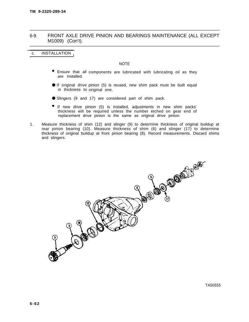
TM 9-2320-289-34
6-9. FRONT AXLE DRIVE PINION AND BEARINGS MAINTENANCE (ALL EXCEPTM1009) (Con’t).
c. INSTALLATION I
• Ensure that allare Installed.
● If original drivein thickness to
NOTE
components are lubricated with lubricating oil as they
pinion (5) is reused, new shim pack must be built equaloriginal one.
● Slingers (9 and 17) are considered part of shim pack.
• If new drive pinion (5) is installed, adjustments in new shim packs’thickness will be required unless the number etched on gear end ofreplacement drive pinion is the same as original drive pinion.
1 . Measure thickness of shim (12) and slinger (9) to determine thickness of original buildup atrear pinion bearing (10). Measure thickness of shim (6) and slinger (17) to determinethickness of original buildup at front pinion bearing (8). Record measurements. Discard shimsand slingers.
TA50555
6-62

TM 9-2320-289-34
6-9. FRONT AXLE DRIVE PINION AND BEARINGS MAINTENANCE (ALL EXCEPTM1009) (Con’t).
NOTE
Perform steps 2 and 3 only if new drive pinion (5) is being installed.
2. Determine proper rear shim pack (9and 12) for setting pinion depth asfollows :
(a)
(b)
(c)
Check number (18) etched ongear end of old drive pinion (5)and locate it in “Old PinionMarking” column of Table 6-3.
Check number (18) etched ongear end of new drive pinion (5)and locate it in “New P i n i o nMarking” column of Table 6-3,
Find point where 2 columnsintersect to determineadjustment number for new rearshim pack (9 and 12).
NOTE
A “+” means add that amount; a “-” means subtract that amount; and “O”means no change.
3. Add or subtract adjustment number found on Table 6-3 to old rear shim pack (9 and 12) todetermine new rear shim pack.
TA50556
6-63

TM 9-2320-289-34
6-9. FRONT AXLE DRIVE PINION AND BEARINGS MAINTENANCE (ALL EXCEPTM1009) (Con’t).
Table 6-3. Pinion Setting Charts.
English U.S. Standard Chart
Old PinIon New Pinion MarkingMarking - 4 - 3 - 2 - 1 0 +1 +2 +3 +4
+4 + 0.008 + 0.007 + 0.006 + 0.005 + 0.004 + 0.003 + 0.002 + 0.001 0
+3 + 0.007 + 0.006 + 0.005 + 0.004 + 0.003 + 0,002 + 0.001 0 -0.001
+2 + 0.006 + 0.005 + 0.004 + 0.003 + 0.002 + 0.001 0 -0.001 -0.002
+1 + 0.005 + 0.004 + 0.003 + 0.002 + 0.001 0 -0.001 -0.002 -0.003
0 + 0,004 + 0.003 + 0.002 + 0.001 0 -0.001 -0.002 -0.003 -0.004
- 1 + 0.003 + 0.002 + 0.001 0 -0.001 -0.002 -0.003 -0.004 -0.005
- 2 + 0.002 + 0.001 0 - 0.001 -0.002 -0.003 -0.004 -0.005 -0.006
- 3 + 0.001 0 -0.001 -0.002 -0.003 -0.004 -0.005 -0.006 -0.007
- 4 0 -0.001 -0.002 -0.003 -0.004 -0.005 -0.006 -0.007 -0.008
Metric Chart
Old PinIon New Pinion MarkingMarking -10 - 8 - 5 - 3 0 +3 +5 +8 + 10
+ 10 + 0.20 + 0.18 + 0.15 + 0.13 + 0.10 + 0.08 + 0.05 + 0.03 0
+ 8 + 0.18 + 0.15 + 0.13 + 0.10 + 0.08 + 0.05 + 0.03 0 -0.03
+ 5 + 0.15 + 0.13 + 0.10 + 0.08 + 0.05 + 0.03 0 -0.03 -0.05
+ 3 + 0.13 + 0.10 + 0.08 + 0.05 + 0.03 0 -0.03 -0.05 -0.08
0 + 0.10 + 0.08 + 0.05 + 0.03 0 -0.03 -0.05 -0.08 -0.10
- 3 + 0.08 + 0.05 + 0.03 0 -0.03 -0.05 -0.08 -0.10 -0.13
- 5 + 0.05 + 0.03 0 -0.03 -0.05 -0.08 -0.10 -0.13 -0.15
- 8 + 0.03 0 -0.03 -0,05 -0.08 -0.10 -0,13 -0.15 -0.18
-10 0 -0.03 -0.05 -0.08 -0.10 -0.13 -0.15 -0.18 -0.20
4 . Install new shim (12) inside rear bearing cup (11 ) bore, Install rear bearing cup in housing (7).
5 . To front shim pack (6 and 17), add or subtract an amount equal to what was added orsubtracted to rear shim pack (9 and 12).
6 . Install front bearing cup (13) into housing (7) bore.
7 . Install new slinger (9) and rear pinion bearing (10) onto drive pinion (5) shaft. Install drivepinion and bearing assembly in housing (7).
6-64

TM 9-2320-289-34
6-9. FRONT AXLE DRIVE PINION AND BEARINGS MAINTENANCE (ALL EXCEPTM1009) (Con’t).
8 . Install new shim (6), front pinion bearing (8), and new slinger (17) on drive pinion (5) shaft.
9 . If removed, install new deflector (15) to flange (2). Install flange, washer (1 6), and flange nut(4). Using flange. holder and flange remover, tighten flange nut to pull flange onto drive pinion(5) and to fully seat front pinion bearing (8). Tighten flange nut to 255 Ib.-ft, (346 N.m).Remove flange holder and flange remover.
TA50557
6-65

TM 9-2320-289-34
6-9. FRONT AXLE DRIVE PINION AND BEARINGS MAINTENANCE (ALL EXCEPTM1009) (Con’t).
NOTE
● When measuring rotating torque, torque reading needed to start drivepinion (5) shaft-turning should be disregarded.
● Front shim pack (6 and 17) should be increased to reduce rotatingtorque. Front shim pack should be decreased to increase rotatingtorque.
10 . Measure rotating torque at flange nut(4) . Rotat ing torque should be20-40 lb.-in. (2-5 N.m) for newbearings, or 10-20 lb.-in. (1-2 N.m)for reused bearings. Adjust front shimpack (6 and 17) by repeating steps 8and 9 if specifications are not met.
11. Remove flange nut (4), washer (16), and flange (2) from drive pinion (5) shaft. Discard flangenut.
12. Coat lips of new pinion oil seal (14) with molybdenum grease and install squarely into housing(7) bore until flush with housing, Install flange (2), washer (16), and new flange nut (4).Tighten flange nut to 255 lb.-ft. (346 N.m).
TA50558
6-66

TM 9-2320-289-34
6-9. FRONT AXLE DRIVE PINION AND BEARINGS MAINTENANCE (ALL EXCEPTM1009) (Con’t).
FOLLOW-ON TASKS:
• Install front axle differential. (See paragraph 6-8)
TA50559
6 - 6 7

TM 9-2320-289-34
6-10. FRONT AND REAR AXLE DRIVE PINION OIL SEAL AND PINION FLANGEMAINTENANCE.
This task covers: a. Removal c. Installationb. Inspection
INITIAL SETUP:
Equipment Condition Materials/Parts
● Truck raised and supported on jack stands. ●
● Propeller shaft disconnected from axle. ●
(See TM 9-2320-289-20) ●
Too/s/Test Equipment
● Flange holder and remover● Torque wrench
One flange nutOne oil sealMolybdenum grease(Item 37, Appendix B)
a REMOVAL
1 .
2 .
At flange nut (4), measure the torquerequired to rotate drive pinion (3) andrecord.
Scribe a line down drive pinion (3)stem, flange nut (4), and flange (2).Ensure that scribe line accuratelyshows relationship of components.Count number of exposed threads ondrive pinion stem and record.
NOTE
Flange nut (4) should not be discarded at this time.
3. Install flange holder (6) on flange (2) and remove flange nut (4) and washer (1). Thread flangeremover bolt into small outside diameter end of flange remover (7). Turn flange remover 1/8turn to a locked position. Turn flange remover while holding flange holder (6) stationary.Remove flange.
TA50560
6-68

TM 9-2320-289-34
6-10. FRONT AND REAR AXLE DRIVE PINION OIL SEAL AND PINION FLANGEMAINTENANCE (Con’t).
4 . Remove oil seal (5) from housing bore and discard.
b. INSPECTION
1. Inspect flange oil seal contact surface, bearing contact surface, drive splines, and universaljoint mount. Replace flange if damaged.
2. If flange deflector requires replacement, remove by tapping from flange. Clean stake points,install new deflector, and stake deflector at 3 new equally spaced positions.
c. INSTALLATION
1. Lubricate cavity between oil seal (5) lips with molybdenum grease and install new oil sealsquarely in bore until flush with housing,
2. Install flange (2). Install washer (1) and original flange nut (4). Install flange holder (6) andtighten flange nut until same number of threads on drive pinion (3) stem are exposed asrecorded during removal and scribe marks are alined. Remove flange nut and discard. Installnew flange nut until snug against washer. Remove flange holder.
TA50561
6-69

TM 9-2320-289-34
6-10. FRONT AND REAR AXLE DRIVE PINION OIL SEAL AND PINION FLANGEMAINTENANCE (Con’t).
CAUTION
Care should be taken to ensure that original rotating torque is notexceeded by more than 5 lb.-in. (0.6 N.m). If working on M1009,exceeding torque specifications may compress spacer on drive pinion (3)shaft too far and require replacement of spacer.
3. Measure torque required to turn drive pinion (3) and compare with torque recorded duringremoval, Install flange holder (6) and tighten flange nut (4) in small increments until rotatingtorque exceeds original by 1–5 lb.-in. (0. 1-0.6 N.m). Remove flange holder.
FOLLOW-ON TASKS:
● Check differential lubricating oil level and fill as required, (See LO 9-2320-289-12)• Connect propeller shaft to axle. (See TM 9-2320-289-20)● Remove jack stands and lower truck.
TA50562
6-70

TM 9-2320-289-34
6-11. STEERING KNUCKLE AND ARM MAINTENANCE (ALL EXCEPT M1009).
This task covers: a. Disassembly b . A s s e m b l y
INITIAL SETUP:
Equipment Condition Materials/Parts
● Steering tie-rod removed. • One gasket(See TM 9-2320-289-20) ● Two seals
● Connecting rod disconnected from steering ● Eight Iockwashersarm (left side). (See TM 9-2320-289-20) ● Grease (Item 36, Appendix B)
● Front axle shaft removed,(See paragraph 6-4)
Tools/Test Equipment General Safety Instructions
● Socket wrench adapter, J-26871-A ● Nuts at steering arm, or bolts at upper● Torque wrench kingpin bearing cap, must be removed
alternately and with caution.
a. DISASSEMBLY
WARNING
Nuts at steering arm or bolts at upper kingpin bearing cap must beremoved alternately and with caution. Compression spring underneathsteering arm or bearing cap could fly up during removal, causing seriousinjury to personnel.
6-71

TM 9-2320-289-34
6-11. STEERING KNUCKLE AND ARM MAINTENANCE (ALL EXCEPT M1009)(Con’t).
NOTE
• On left side, steering arm (3) is installed to steering knuckle (8) with 4nuts (2). On right side, upper kingpin bearing cap is installed tosteering knuckle with 4 bolts and Iockwashers.
● Left side disassembly is given.
1. Remove 4 nuts (2) alternately at steering arm (3). Remove steering arm, spring (4), andspring retainer (5). Remove gasket and discard. If present, discard 4 Iockwashers.
2 . Remove 4 bolts (16), Iockwashers,and lower kingpin bearing cap (15)from steering knuckle (8). DiscardIockwashers,
TA50563
6-72

TM 9-2320-289-34
6-11. STEERING KNUCKLE AND ARM MAINTENANCE (ALL EXCEPT M1009)(Con’t).
3. Remove kingpin bushing (7) from topof steering knuckle (8). Removesteering knuckle from axle housing(9) .
NOTE
Upper kingpin (6) is tightened to 550 lb.-ft, (746 N.m).
4. Remove seal (10) from upper kingpin(6). Remove upper kingpin from axlehousing (9). Discard seal.
5. inspect upper kingpin (6) and kingpinbushing (7) for damage. Replace ifdamaged.
TA50564
6-73

TM 9-2320-289-34
6-11. STEERING KNUCKLE AND ARM MAINTENANCE (ALL EXCEPT M1009)(Con’t).
6 . Remove seal (14) and bearing (13). Inspect bearing for damage and binding, Replace ifdamaged or binding. Discard seal. If damaged, remove bearing cup (12) and retainer (11).
7 . Inspect all grease fittings and replace if damaged.
b. ASSEMBLY
NOTE
● On left side, steering arm is installed to steering knuckle (8) with 4nuts. On right side, upper kingpin bearing cap is installed to steeringknuckle with 4 bolts and Iockwashers.
● Left side assembly is given,
• Seal (14) will protrude slightly from surface of axle housing (9) flangewhen installed.
1. If removed, assemble retainer (11) and bearing cup (12), and install to axle housing (9)flange. Fill area in retainer with grease. Grease bearing (13) and install, Install new seal (14).
TA60565
6-74

TM 9-2320-289-34
6-11. STEERING KNUCKLE AND ARM MAINTENANCE (ALL EXCEPT M1009)(Con’t).
2 . Install upper kingpin (6) to axle housing (9) and tighten to 550 Ib.-ft. (746 N.m). Install newseal (10) to upper kingpin with lip facing up.
3 . Grease upper kingpin (6) and install steering knuckle (8) to axle housing (9).
TA50566
6-75

TM 9-2320-289-34
6-11. STEERING KNUCKLE AND ARM MAINTENANCE (ALL EXCEPT M1009)(Con’t).
4 . Install lower kingpin bearing cap (15)with 4 new Iockwashers and bolts(16). Tighten bolts to 80 Ib.-ft.(108 Nom).
5 . Install kingpin bushing (7) to top ofsteering knuckle (8) with ridge onbushing indexed with slot in axlehousing (9).
TA50567
6 - 7 6

TM 9-2320-289-34
6-11. STEERING KNUCKLE AND ARM MAINTENANCE (ALL EXCEPT M1009)(Con’t).
CAUTION
Nuts (2) at steering arm (3) or bolts at upper kingpin bearing cap shouldbe installed alternately and in increments. Failure to follow this cautionmay result in damage to stud threads or to bolts.
NOTE
On right side, 4 new Iockwashers are used with bolts.
6 . Assemble spring retainer (5) with collar facing up and spring (4) on kingpin bushing (7) overupper kingpin (6). Install new gasket and steering arm (3) over steering knuckle studs (1).Install 4 nuts (2), and tighten alternately and in increments to 80 Ib.-ft. (108 N.m).
FOLLOW-ON TASKS:
• Lubricate steering knuckle and arm. (See LO 9-2320-289-12)● Install front axle shaft. (See paragraph 6-4)● Connect connecting rod to steering arm if removed. (See TM 9-2320-289-20)● Install steering tie-rod. (See TM 9-2320-289-20)
TA50568
6-77

TM 9-2320-289-34
6-12. STEERING KNUCKLE, ARM, AND BALL JOINT MAINTENANCE (M1009).
This task covers: a. Disassembly b. Assembly
INITIAL SETUP:
Equipment Condition
● Steering tie-rod removed.(See TM 9-2320-289-20)
• Connecting rod disconnected from steeringarm (left side only), (See TM 9-2320-289-20)
● Front axle shaft removed. (See paragraph 6-4)
Tools/Test Equipment
● Ball joint adapter set, J-23454-D● Ball stud adjuster sleeve, J-23447● Lower ball joint remover, J-33122• “C“ clamp● Snapring pliers● Torque wrench
Materials/Parts
● One flat washer• One steering knuckle socket repair kit● One cotter pin● Three locknuts
a. DISASSEMBLY
●
●
●
●
NOTE
Left side steering knuckle (5),arm ( l ) , and bal l jo int (12)disassembly is given.
Right side steering knuckle (5)has no steering arm (1).
It may be necessary to applyheat to loosen steering arm (1).
If removing steering arm (1),perform step 1,
1. Remove 3 locknuts (3) at steeringarm (1), Remove 3 stud adapters(4). Remove steer ing arm fromsteering knuckle (5) . Discardlocknuts.
TA50569
6-78

TM 9-2320-289-34
6-12. STEERING KNUCKLE, ARM, AND BALL JOINT MAINTENANCE (M1009)(Con’t).
2 . Remove cotter pin (8) from upper ball stud nut (9). Remove upper and lower ball stud nuts (9and 10). Discard cotter pin and upper and lower ball stud nuts.
3 . Loosen upper ball stud adjusting sleeve (7) until flush with underside of axle housing (6).
4 . Use a suitable wedge-shaped tool between lower ball stud and axle housing (6). Tap on tool torelease steering knuckle (5). Repeat at upper ball stud and remove steering knuckle from axlehousing.
NOTE
Ensure that lower ball joint (12)has been removed beforerepairing upper ball joint.
5 . Place steering knuckle (5) in vise.Remove snapring at lower ball joint(12). Using adapters J-23454-1 andJ-23454-4, install ball joint removaltools on lower ball joint. Install f I atwasher between “ C“ clamp andadapter (11). Tighten “C“ clamp untillower ball joint is pressed out. Discardlower ball joint and snapring.
6 . Place ball joint removal tools on upperball joint (12) and remove in samemanner as lower ball joint. Discardupper ball joint.
6-79

TM 9-2320-289-34
6-12. STEERING KNUCKLE, ARM, AND BALL JOINT MAINTENANCE (M1009)(Con’t).
NOTE
If stop (13) requires replacement,position and number of exposedth reads shou ld be no ted fo rinstallation.
7 . Inspect 3 steering arm studs (2), 6spindle bolts (14), and stop (13).Replace if damaged.
8 . Inspect upper ball stud adjustingsleeve (7) at axle housing (6) andreplace if damaged.
b . ASSEMBLY
●
●
●
Left
NOTE
side steering knuckle (5), arm, and ball joint (12) assembly isgiven,
Ml 009 steering knuckle ball joints (12) do not require lubrication.
Ensure that lower ball joint (12) (ball joint without cotter pin hole Instud) is straight before it is pressed in place.
1 . Position new lower ball joint (12) insteering knuckle (5). Using ball jointinstallation tools and adaptersJ-23454-2 and J-23454-4, press lowerball joint into place. Install newsnapring.
2 . Remove rubber retaining cup fromnew upper ball joint (12). Positionupper ball joint at steering knuckle (5)and install in same manner as lowerball joint. Install rubber retaining cupto upper ball joint.
6-80

TM 9-2320-289-34
6-12. STEERING KNUCKLE, ARM, AND BALL JOINT MAINTENANCE (M1009)(Con’t).
3 . Position steering knuckle (5) and sockets at axle housing (6). Install lower ball stud nut (10)finger tight.
Torque values insteering knuckle
NOTE
steps 4-7 are necessary to maintain proper alinement of(5) to axle housing (6).
4 . Push up on steering knuckle (5) to keep ball socket from turning in knuckle and partially tightenlower ball stud nut (10) to 30 Ib.-ft. (41 N.m).
5. Tighten upper ball stud adjusting sleeve (7) to 50 ft.-lb. (68 N.m).
NOTE
Nut (9) should be tightened only, to aline holes for cotter pin (8).
6 . Install new upper ball stud nut (9) and tighten to 100 Ib.-ft. (136 N.m). Install new cotter pin(8) .
7 . Fully tighten lower ball stud nut (10) to 70 Ib.-ft. (95 N.m).
TA50572
6-81

TM 9-2320-289-34
6-12. STEERING KNUCKLE, ARM, AND BALL JOINT MAINTENANCE (M1009)(Con’t).
8. If removed, install steering arm (1)over 3 steering arm studs (2). Install3 stud adapters (4). Install 3 newlocknuts (3) and tighten to 90 lb.-ft.(122 N.m).
FOLLOW-ON TASKS:
● Install front axle shaft. (See paragraph 6-4)• Connect connecting rod to steering arm if removed. (See TM 9-2320-289-20)● Install steering tie-rod. (See TM 9-2320-289-20)
TA50573
6-82

TM 9-2320-289-34
6-13. REAR AXLE ASSEMBLY REPLACEMENT.
This task covers: a . Remova l b. Instal lat ion
INITIAL SETUP:
Equipment Condition Tools/Test Equipment
Parking brake released.Truck raised and frame supported onjack stands.Rear wheels removed.(See TM 9-2320-289-20)Rear propeller shaft disconnected from rearaxle differential. (See TM 9-2320-289-20)Parking brake cable disconnected atequalizer. (See TM 9-2320-289-20)Rear brake lines disconnected from wheelcylinders and differential housing.(See TM 9-2320-289-20)Proportioning valve lever disconnected fromdifferential housing. (See TM 9-2320-289-20)Rear shock absorbers disconnected fromaxle. (See TM 9-2320-289-20)Rear stabilizer bar removed (M1028A2and M1028A3). (See TM 9-2320-289-20)
● Torque wrench
Personnel Required● MOS 63W (2)
General Safety Instructions● Rear axle assembly is heavy. Use
extreme caution, provide support, anduse assistance during removal andinstallation.
Change 2 6-83

TM 9-2320-289-34
6-13. REAR AXLE ASSEMBLY REPLACEMENT (Con’t).
a. REMOVAL
1 . Slide clamp up rear axle vent hose (8) and disconnect rear axle vent hose from rear axledifferential (7).
2 . Place suitable jack under rear axle differential (7).
WARNING
Rear axle assembly (6) is heavy. Use extreme caution, provide support, anduse assistance during removal. Failure to follow this warning may result inserious injury to personnel or damage to rear axle assembly.
NOTE
For M1028A2 and M1028A3, skip step 3 and perform step 4.
3. Remove 4 nuts (3), washers (2), 2“U” bolts (5), and anchor plate (4) ateach spring assembly (1). Lower rearaxle assembly (6) and remove, Ifpresent, remove 2 shims (9) from axlehousing.
4. Remove 4 nuts (3), washers (2),adapter (3.1), 4 washers (3,2), 2 “U”bolts (5), and anchor plate (4) at eachspring assembly (1). Lower rear axleassembly (6) and remove. If present,remove 2 shims (9) from axlehousing.
6-84 Change 2

TM 9-2320-289-34
6-13. REAR AXLE ASSEMBLY REPLACEMENT (Con’t).
b. INSTALLATION
WARNING
Rear axle assembly (6) is heavy. Use extreme caution, provide support, anduse assistance during installation. Failure to follow this warning may resultin serious injury to personnel or damage to rear axle assembly,
NOTE
For M1028A2 and M1028A3, skip steps 1 and 2 and perform steps 2.1 and2.2.
1 . Position rear axle assembly (6) on suitable jack and raise into position. If removed, install 2 shims(9) on axle housing with thinner edges facing front. Aline holes in shims with holes in axle housingand spring assembly (1) center bolt.
2 . Loosely install anchor plate (4) at each spring assembly with with 2 “ U“ bolts (5), 4 washers (2),and nuts (3). Install all nuts to uniform engagement on “U” bolts to retain and position anchorplate.
Change 2 6-85

TM 9-2320-289-34
6-13. REAR AXLE ASSEMBLY REPLACEMENT (Con’t).
2.1.
2.2.
3.
4 .
5.
NOTE
Adapters (3.1) are mismarked on casting as to left-hand and right-hand.Install adapters as shown, with ribs up and curved arm to rear facinginboard.
Position rear axle assembly (6) onsuitable jack and raise into position. Ifremoved, install 2 shims (9) on axlehousing with thinner edges facingfront. Aline holes in shims with holes inaxle housing and spring assembly (1)center bolt.
Loosely install anchor plate (4) andadapter (3, 1 ) at each spring assemblywith 2 “U” bolts (5), 4 washers (3.2),washers (2), and nuts (3). Install allnuts to uniform engagement on “U”bolts to retain and position anchorplate and adapter,
NOTE
All nuts (3) must be tightened evenly to ensure that “U” bolts (5) and springassemblies (1) seat properly,
Partially tighten all nuts (3) in diagonal sequence to 25 Ib.-ft, (34 N.m). Fully tighten nuts onM1009 in same diagonal sequence to 145 Ib.-ft. (197 N.m). On M1028A2, tighten all nuts insame diagonal sequence to 150 Ib.-ft. (180 N.m). On all others, tighten all nuts in same diagonalsequence to 170 Ib.-ft. (231 N.m).
Remove jack from rear axle differential (7),
Connect rear axle vent hose (8) to rear axle differential (7) and install clamp,
6-85.0 Change 2

TM 9-2320-289-34
6-13. REAR AXLE ASSEMBLY REPLACEMENT (Con’t).
FOLLOW-ON TASKS:
● Install rear stabilizer bar (M1028A2 and M1028A3). (See TM 9-2320-289-20)● Connect rear shock absorbers to axle. (See TM 9-2320-289-20)● Connect proportioning valve lever to differential housing. (See TM 9-2320-289-20)● Connect rear brake lines to wheel cylinders and differential housing. (See TM 9-2320-289-20)● Connect parking brake cable at equalizer. (See TM 9-2320-289-20)● Connect rear propeller shaft to rear axle differential. (See TM 9-2320-289-20)● Install rear wheels. (See TM 9-2320-289-20)●
●
Remove jack stands and lower truck.Road test truck and check torque of “U” bolt nuts.
Change 2 6-85.1

TM 9-2320-289-34
6-14. REAR AXLE SHAFT, OUTER SEAL, BEARING, AND BACKING PLATEREPLACEMENT (M1009).
This task covers: a. Removal c . Installationb. Cleaning and inspection
INITIAL SETUP:
Equipment Condition Materials/Parts
●
●
●
●
Brake drum removed.(See TM 9-2320-289-20)Brake shoes and attaching hardwareremoved (if removing backing plate),(See TM 9-2320-289-20)Rear brake line disconnected from wheelcylinder (if removing backing plate),(See TM 9-2320-289-20)Emergency brake cable disconnected frombacking plate (if removing backing plate).(See TM 9-2320-289-20)
●
●
●
●
●
●
One bearingOne differential cover gasketOne IockscrewOne rear axle outer oil sealFour IockwashersDry cleaning solvent(Item 23, Appendix B)Grease (Item 36, Appendix B)Gear lubricating oil(Item 44, Appendix B)
Tools/Test Equipment General Safety Instructions
● Annular bearing inserter, J-23690 ● Dry cleaning solvent is flammable and● Axle seal installer, J-29713 must not be used near open flame.● Drive handle, J-8092 Use only in a well-ventilated area.● Puller kit • Compressed air used for cleaning● Torque wrench purposes should never exceed 30 psi
(207 kPa).
a. REMOVAL
NOTE
● If removing rear axle shaft (8), perform steps 1-3.
● If removing rear axle outer oil seal, perform steps 1-4.
● If removing rear axle outer oil seal and bearing, perform steps 1-3, and5.
● If removing backing plate, perform steps 1-3 and 6.
● Ensure that rear axle differential cover is clean before proceeding.
1. Remove 10 bolts at differential cover, Carefully move brake line and bracket, brake line blockbracket, and emergency brake cable mounting bracket out of the way. DO NOT kink lines.Remove differential cover and allow all lubricating oil to drain into a suitable container. Removedifferential cover gasket and discard.
CAUTION
When removing rear axle shaft (8), ensure that outer oil seal is notdamaged. Failure to follow this caution may result in damage to outer oilseal and axle lubricant leakage.
6-86

TM 9-2320-289-34
6-14. REAR AXLE SHAFT, OUTER SEAL, BEARING, AND BACKING PLATEREPLACEMENT (M1009) (Con’t).
CAUTION
●
2 .
3 .
DO NOT allow pinion shaft (4)to come completely out,
Rotate differential case (2) assemblyas required to gain access toIockscrew (3). Support pinion shaft(4) so that it does not fall intodifferential case assembly. RemoveIockscrew. Withdraw pinion shaft partway and rotate differential caseassembly until pinion shaft touchesbottom edge of housing (1).
Rotate rear axle shaft (8) until “C”lock (5) is alined with thrust block (6).Push flange of rear axle shaft towardthe differential case (2) assembly andremove “C“ lock. Remove rear axleshaft. Loosely reinstall pinion shaft(4) and Iockscrew (3) to ensure thatdifferential gears do not becomemispositioned.
TA50575
6-87

TM 9-2320-289-34
6-14. REAR AXLE SHAFT, OUTER SEAL, BEARING, AND BACKING PLATEREPLACEMENT (M1009) (Con’t).
4 .
5 .
6 .
NOTE
Perform step 4 if removing outer oil seal (10) only.
Insert button end of rear axle shaft (8) behind steel case of outer oil seal (10), Remove outeroil seal and discard.
NOTE
Perform step 5 if removing outer oil seal (10) and bearing (11).
Insert puller into bore so that tool grasps behind bearing (11). Remove bearing and outer oilseal (1 O). Discard bearing and outer oil seal.
NOTE
Perform step 6 only if backing plate (15) is damaged.
Remove 4 nuts (13), Iockwashers (14), bolts (16), and remove backing plate (15) from axlehousing (1 2), Discard Iockwashers.
TA50576
6 - 8 8

TM 9-2320-289-34
6-14. REAR AXLE SHAFT, OUTER SEAL, BEARING, AND BACKING PLATEREPLACEMENT (M1009) (Con’t).
b. CLEANING AND INSPECTION
WARNING
●
●
Dry cleaning solvent P-D-660 is toxic and flammable. Always wearprotective goggles and gloves and use only In a well-ventilated area.Avoid contact with skin, eyes, and clothes and DO NOT breathe vapors.DO NOT use near open flame or excessive heat. The solvent’s flashpoint is 100°F-138°F (38°C-59°C). If you become dizzy while usingcleaning solvent, immediately get fresh air and medical help. If solventcontacts eyes, immediately wash your eyes with water and get medicalaid.
Compressed air used-for cleaning purposes should never exceed 30 psi(207 -kPa). Use only effective chip guarding and personnel protectiveequipment (goggles/shield, gloves, etc.). Failure to follow this warningmay result in serious Injury to personnel.
1. Clean all removed components in dry cleaning solvent and dry with compressed air. Clean allgasket material from differential cover and housing.
2. Inspect rear axle shaft for damage. Replace If damaged.
3. Inspect wheel studs (9) at rear axle shaft for damage. Replace if damaged.
4. Inspect backing plate for damage. Replace if damaged.
c. INSTALLATION
NOTE
● If installing backing plate (15), perform step 1.
● If installing rear axle bearing (11), perform step 2.
● If installing rear axle outer oil seal (10), performstep 3.
● If Installing rear axle shaft (8), perform steps 4-6.
1. If removed, install backing plate (15) on axle housing (12) with 4 bolts (16), new Iockwashers(14), and 4 nuts (13). Tighten nuts to 35 Ib.-ft. (47 Nom).
2. Lubricate new rear axle bearing (11) with grease. Install new rear axle bearing until bearinginstaller tool bottoms against tube of axle housing (12).
3. Lubricate cavity between new outer oil seal (10) lips with grease. Install new outer oil seal untilseal installer tool bottoms against tube of axle housing (12) and outer oil seal is flush with endof tube.
6-89

TM 9-2320-289-34
6-14. REAR AXLE SHAFT, OUTER SEAL, BEARING, AND BACKING PLATEREPLACEMENT (M1009) (Con’t).
WARNING
Ensure that “C” lock (5) is correctly seated inFailure to correctly seat “C” lock may result inserious Injury or death to personnel.
CAUTION
differential side gear (7),loss of truck’s wheel and
When Installing rear axle shaft (8), ensure that splines on end of shaft donot damage outer oil seal. Failure to follow this caution may result indamage to outer oil seal and exle lubricant leakage.
4 . Slide rear axle shaft (8) into position with splines engaged into differential side gear (7),Remove Iockscrew (3) and partially withdraw pinion shaft (4), Position “C” lock (5) on end ofrear axle shaft, Pull rear axle shaft flange outward and seat “C” lock in differential side gear,Discard Iockscrew.
TA50577
6-90

TM 9-2320-289-34
6-14. REAR AXLE SHAFT, OUTER SEAL, BEARING, AND BACKING PLATEREPLACEMENT (M1009) (Con’t).
5 . Aline hole in pinion shaft (4) withIockscrew (3) hole in differential case(2) assembly. Install pinion shaft andnew Iockscrew. Tighten Iockscrew to25 Ib.-ft. (34 N.m).
6 . Install new gasket and differentialcover. Carefully position emergencybrake cable mounting bracket, brakeline block bracket, and brake line andbracket. DO NOT kink lines. Install 10bolts and t igh ten to 35 Ib.-ft.(47 N.m).
FOLLOW-ON TASKS:
● Connect emergency brake cable to backing plate if removed. (See TM 9-2320-289-20)● Connect rear brake line to wheel cylinder if removed. (See TM 9-2320-289-20)● Install brake shoes and attaching hardware if removed. (See TM 9-2320-289-20)● Install brake drum. (See TM 9-2320-289-20)● Fill rear axle differential with lubricating oil. (See LO 9-2320-289-12)
TA50578
6-91

TM 9-2320-289-34
6-15. REAR AXLE DIFFERENTIAL MAINTENANCE (ALL EXCEPT M1009).
This task covers: a. Removal d. Assemblyb. Disassembly e. Installationc. Cleaning and Inspection
INITIAL SETUP:
Equipment Condition Materials/Parts
● Rear axle shafts removed. ●
(See TM 9-2320-289-20) ●
●
Tools/Test Equipment● Wrench nut (differential), J-24429 ●
● Dial indicator● Puller kit ●
● Spring tester● Torque wrench ●
Manual References
● TM 9-214
General Safety Instructions
One differential cover gasketSixteen IockwashersDry cleaning solvent(Item 23, Appendix B)Prussian blue dye(Item 24, Appendix B)Gear lubricating oil(Item 44, Appendix B)Wiping rags (Item 53, Appendix B)
● Dry cleaning solvent is flammable and must not be used near open flame. Use only in awell-ventilated area.
Ž Compressed air used for cleaning purposes should never exceed 30 psi (207 kPa).● Tightly hold differential case assembly together to absorb spring pressure during removal and
installation of ring gear bolts.
NOTE
When removing differential cover bolts, location of clips Should be noted.
1 . Place a suitable container under housing. Remove 14 bolts at differential cover and move venttube bracket, brake line and bracket, and proportioning valve lever out of the way. Removedifferential cover and allow all lubricating oil to drain. Remove gasket, if present, and discard.
NOTE
Ensure that bearing caps (1) are marked for installation in same position.
2 . Remove bolt (2), washer (3), and adjusting nut lock (7) from each bearing cap (1), Remove 4bolts (5), Iockwashers (6), and 2 bearing caps. Discard Iockwashers.
3. Loosen 2 adjusting nuts (8). Remove differential case (9) assembly from housing. Remove 2bearing cups (10) from differential case assembly side bearings (11) and tag for installation.
6-92

TM 9-2320-289-34
6-15. REAR AXLE DIFFERENTIAL MAINTENANCE (ALL EXCEPT M1009) (Con’t).
b . DISASSEMBLY
1. Place differential case (9) assemblyin vise.
CAUTION
Ensure that pul ler f ingers areinstalled Into n o t c h e s o fdifferential case (9) assembly sothat only inner race Is contacted.Failure to follow this caution mayresult in damage to side bearings(11).
2 . Tag side bearings (11) for assemblyon their original side. Install bearingpuller on side bearing and removeside bearing. Repeat for remainingside bearing,
TA50579
6-93

TM 9-2320-289-34
6-15. REAR AXLE DIFFERENTIAL MAINTENANCE (ALL EXCEPT M1009) (Con’t).
WARNING
Tightly hold differential case (9) assembly together to absorb springpressure as last ring gear bolts (12) are removed. Failure to follow thiswarning may result in injury to personnel or damage to differential caseassembly components.
NOTE
Shop rags placed around vise will help protect ring gear (4) teeth fromdamage should ring gear fall during disassembly.
3 . Scribe a line on differential case (9)assembly and ring gear (4) to ensureassembly in same position. Remove12 ring gear bolts (12) andIockwashers (13). Using a soft-facedhammer, tap ring gear loose fromdifferential case assembly. Removedifferential case assembly from viseand remove ring gear. DiscardIockwashers.
4 . Separate differential case (9)assembly halves.
NOTE
Ensure that differential case (9) assembly internal components are keptseparated so that they may be assembled in same position.
5 . From 1 differential case (9) half remove side gear (14), retainer (15), spring (1 6), drivenclutch (17), and spider assembly (18). From other differential case half remove driven clutch,spring, retainer, and side gear.
TA50580
6-94

TM 9-2320-289-34
6-15. REAR AXLE DIFFERENTIAL MAINTENANCE (ALL EXCEPT M1009) (Con’t).
c. CLEANING AND INSPECTION I
WARNING
● Dry cleaning solvent P-D-680 IS toxic and flammable. Always wearprotective goggles and gloves and use only in a well-ventilated area.Avoid contact with skin, eyes, and clothes and DO NOT breathe vapors.DO NOT use near open flame or excessive heat, The solvent’s flashpoint is 100°F-138°F (38°C-59°C). If you become dizzy while usingcleaning solvent, Immediately get fresh air and medical help, If solventcontacts eyes, immediately wash your eyes with water and get medicalaid.
Ž Compressed air used for cleaning purposes should never exceed 30 psi(207 kPa). Use only effective chip guarding and personnel protectiveequipment (goggles/shield, gloves, etc.). Failure to follow this warningmay result in serious injury to personnel.
CAUTION
If major components (e.g. spider assembly or driven clutch assemblies)show excessive wear or damage, the entire no-spin unit should bereplaced. If any part is replaced, mating parts should also be replaced asthey are probably also damaged. Failure to follow this caution may resultin a recurrence of original problem.
1 . Clean all components in dry cleaning solvent and dry with compressed air.
2. Clean and inspect side bearings in accordance with TM 9-214,
TA50581
6-95

TM 9-2320-289-34
6-15. REAR AXLE DIFFERENTIAL MAINTENANCE (ALL EXCEPT M1009) (Con’t).
3 . Inspect splines on driven clutches and remove any burrs or nicks found. If driven clutch teethare chipped, or if burrs and nicks cannot be repaired, replace driven clutch.
4 . Inspect holdout ring (19) on driven clutches (17) for fractures or chipped teeth. Replace iffractured or chipped.
5 . inspect teeth on spider (18) and center cam (20) for fractures or chipping. Inspect center camto ensure that it moves freely in spider, Replace spider assembly if fractured, chipped or ifcenter cam does not move freely.
6 . Inspect side gears for damage, Replace if damaged.
7 . Inspect the fit of side gear to mating axle shaft, Replace side gear if it binds in axle shaft.
8 . Using a spring tester, measure each spring load at operating height. When height of spring is0.72 in. (18.29 mm), load should be 65 lb.±6 lb. (30 kg ±3 kg). Replace springs ifmeasurement is not within specification.
9 . Inspect differential case for damage. Remove any nicks or burrs found, Replace if damaged orif nicks or burrs cannot be removed.
NOTE
If ring gear is replaced, ring gear bolts and drive pinion must also bereplaced. (See paragraph 6-17)
10 . inspect ring gear and ring gear bolts for damage. Replace if damaged.TA60582
8-96

TM 9-2320-289-34
6-15. REAR AXLE DIFFERENTIAL MAINTENANCE (ALL EXCEPT M1009) (Con’t).
d. ASSEMBLY
NOTE
Ensure that all components are lubricated with lubricating oil as they areassembled.
1 . Place ring gear (4) and flanged half ofdifferential case (9) on woodenblocks with bearing end of hub facingdownward.
2 . Place hub of side gear (14) into bore of differential case (9). Ensure that side gear will rotatefreely. Install retainer (15) over side gear splines with retainer lip facing upwards and retainerseated against side gear shoulder.
TA50583
6-97

TM 9-2320-289-34
6-15. REAR AXLE DIFFERENTIAL MAINTENANCE (ALL EXCEPT M1009) (Con’t).
3 . Install spring (16) over side gear (14) spline against retainer (15) lip with smaller end of springagainst retainer.
4 . Install driven clutch (17) over spring (16) with teeth facing upwards.
NOTE
Ensure that slot in driven clutch (17) holdout ring (19) engages longspider key (21).
5 . Place spider (18) assembly over driven clutch (17),
6 . Place remaining driven clutch (17) over spider (18) assembly.
TA50584
6-98

TM 9-2320-289-34
6-15. REAR AXLE DIFFERENTIAL MAINTENANCE (ALL EXCEPT M1009) (Con’t).
7 . Assemble remaining retainer (15),spring (1 6), and side gear (14).
WARNING
Tightly hold differential case (9)assembly together to absorbspring pressure until 2 or morering gear bolts (12) are installed.Failure to follow this warning mayresult in injury to personnel ord a m a g e t o differential caseassembly components.
NOTE
Ensure that r ing gear (4) anddif ferent ial case (9) assemblyhalves are assembled as marked.
8 . Install remaining differential case (9)half over side gear (14) andcompress springs (16). Install 12 newIockwashers (13) and ring gear bolts(12). Tighten bolts alternately to120 Ib.-ft. (163 N.m).
TA50585
6-99

TM 9-2320-289-34
6-15. REAR AXLE DIFFERENTIAL MAINTENANCE (ALL EXCEPT M1009) (Con’t).
Side bearings (11 )
NOTE
should rotate
9 . Install 2 side bearings (11) as tagged.
freely once installed.
e . INSTALLATION
1 . Install 2 bearing cups (10) as taggedto side bearings (11). Installdifferential case (9) assembly insidehousing.
TA50586
6-100

TM 9-2320-289-34
6-15. REAR AXLE DIFFERENTIAL MAINTENANCE (ALL EXCEPT M1009) (Con’t).
2 .
3 .
4 .
5 .
Install 2 bearing caps (1) in theiroriginal positions with 4 newIockwashers (6) and bol ts (5) ,Tighten bolts just enough to holdbearing caps in place.
Loosen right side adjusting nut (8)and tighten left side adjusting nut untilring gear (4) contacts drive piniongear without binding. This is zero(“O”) lash.
Back off left side adjusting nut (8)approximately 2 slots. Install left sideadjusting nut lock (7), washer (3),and bolt (2) to left side bearing cap( l ) . Tighten bolt to 20 Ib.-ft.(27 N.m).
Tighten right side adjusting nut (8)until differential case (9) assembly isforced into solid contact with left sideadjusting nut, Loosen right sideadjusting nut until it is free frombearing contact then retighten untilcontact is re-established.
6 . When in contact, tighten right side adjusting nut (8) 2 slots if side bearings (11) are reused or3 slots if side bearings are new. Install adjusting nut lock (7), washer (3), and bolt (2) to rightside bearing cap (1). Tighten bolt to 20 lb.-ft. (27 N.m).
7 . Tighten 4 bolts (5) to 135 Ib.-ft. (183 N.m).
TA50587
6-101

TM 9-2320-289-34
6-15. REAR AXLE DIFFERENTIAL MAINTENANCE (ALL EXCEPT M1009) (Con’t).
NOTE
At this point, side bearings are preloaded. If any additional adjustmentsare required, ensure that preload remains as established. If 1 adjusting nut(8) is loosened, the other must be tightened an equal amount to maintainthis preload.
8 . Mount dial indicator (22) on housingand measure backlash between ringgear (4) and drive pinion gear. Rockring gear back and forth to measurebacklash. Backlash shou ld bebetween 0.003-0.012 in. (0.076-0.305 mm) with(0.1 27-0.203 mm)
NOTE
I f ad jus t ing nu t
0.005-0.008 in.preferred,
(8) requiresadjustment, bolts (2 and 5) mustbe loosened. Once finaladjustments have been made,bo l ts mus t be re t igh tened toproper torque.
9 . If backlash is more than 0.012 in.(0.305 mm), loosen right adjustingnut (8) 1 slot and tighten left adjustingnut 1 slot. If backlash is less than0.003 in. (0.076 mm), loosen leftadjusting nut 1 slot and tighten rightadjusting nut 1 slot. Remove dialindicator (22) from housing.
NOTE
If ring gear (4) and drive pinion were replaced, perform steps 10-13 tocheck for proper gear tooth contact pattern.
10. Wipe any lubricant from housing and clean each tooth of ring gear (4).
11. Using a medium stiff brush, sparingly apply prussian blue dye to all ring gear (4) teeth. Area ofdrive pinion tooth contact should be visible when drive pinion is engaged by hand.
NOTE
Excessive turning of ring gear (4) is not recommended. Ring gear shouldbe turned only enough to provide tooth contact pattern,
12. Apply load until it takes a torque of 40-50companion flange so that ring gear (4) turnsturns 1 full revolution in opposite direction.
Ib.-ft, (54-68 N.m) to turn drive pinion. Turn1 full revolution, then reverse so that ring gear
TA50588
6-102

TM 9-2320-289-34
6-15. REAR AXLE DIFFERENTIAL MAINTENANCE (ALL EXCEPT M1009) (Con’t),
1 3 . Contact pattern should be centrally located up and down on the face of the ring gear (4) teeth.Compare tooth contact pattern on ring gear with examples shown and make adjustments asindicated.
NOTE
Ensure that differential cover and magnet are clean.
14. Carefully position vent tube bracket, brake line and bracket, and proportioning valve lever athousing. DO NOT kink lines. Install new differential cover gasket and differential cover with 14bolts. Tighten bolts to 35 Ib.-ft. (47 N.m).
FOLLOW-ON TASKS:
• Install rear axle shafts. (See TM 9-2320-289-20)• Fill rear axle differential with lubricating oil. (See LO 9-2320-289-12)
TA50589
6-103

TM 9-2320-289-34
6-15.1. REAR AXLE DIFFERENTIAL MAINTENANCE (M10028A2).
This task covers: a. Removal d. Assemblyb. Disassembly e. Installationc. Cleaning and Inspection
INITIAL SETUP:
Equipment Condition Materials/Parts
● Rear axle assembly removed. ●
(See paragraph 6-1 3) ●
● Rear axle shafts removed.(See TM 9-2320-289-20) ●
●
●
●
●
●
Two preformed packingsDry cleaning solvent(Item 23, Appendix B)Prussian blue dye (Item 24, Appendix B)Gear lubricating oil(Item 44, Appendix B)Wiping rags (Item 53, Appendix B)RTV sealant (Item 57, Appendix B)Tags (Item 64, Appendix B)Masking tape (Item 68, Appendix B)
Tools/Test Equipment Manual References
●
●
●
●
●
●
Axle housing spreader, D-167 ● TM 9-214Dial indicatorFour-piece puller adaptor set, DD-914-95(use with DD-914P and D-914-8)Puller DD-914PPuller adapter, D-914-8Torque wrench
General Safety Instructions
● Dry cleaning solvent is flammable and must not be used near open flame. Use only in awell-ventilated area.
● Compressed air used for cleaning purposes should never exceed 30 psi (207 kPa).
a. REMOVAL
1.
2.
Mount axle on axle stand.
Place a suitable container under axlehousing. Remove 10 bolts (1) anddifferential cover (2), and allow alllubricating oil to drain. Remove oldRTV sealant from differential coverand axle housing.
6-103.0 Change 1

TM 9-2320-289-34
6-15.1. REAR AXLE DIFFERENTIAL MAINTENANCE (M1028A2) (Con’t).
NOTE
Side bearing caps (3) are stamped with letters which match letters stampedon case. Note letters for installation alinement, If side bearing caps are notstamped, mark side bearings caps and axle housing before removal.
3. Remove 4 bolts (4) and 2 side bearingcaps (3).
4 . Position axle housing spreader (5) withtool dowels fitted into recesses in axlehousing. Install dial indicator (6) fromedge of axle housing to opposite edgeof axle housing. Ensure that dialindicator is preloaded. Set dialindicator to “0, ”
CAUTION
Axle housing should not be spreadmore than 0.015 in. (0.381 mm),Failure to follow this caution maycause damage and permanentdistortion to axle housing.
5 . Spread axle housing to 0.015 in.(0.381 mm). Remove dial indicator(6) .
Change 1 6-103.1

TM 9-2320-289-34
6-15.1. REAR AXLE DIFFERENTIAL MAINTENANCE (M1028A2) (Con’t).
NOTE
Relieve tension on axle housing spreader and remove from axle housing assoon as possible.
6. Remove differential case (8) assembly from axle housing. Remove and tag 2 side bearing cups(7) for installation.
7 . Remove 2 preformed packings (9) from axle housing. Discard preformed packings.
1 .
2 .
3 .
NOTE
DO NOT remove side bearings orring gear unless damaged. If sidebearings and ring gear are not to bereplaced, go to step 6.
Inspect differential side bearings inaccordance with TM 9-214.
Inspect ring gear for damage.
Place differential case (8) assembly in”vise.
b. DISASSEMBLY
6-103.2 Change 1

TM 9-2320-289-34
6-15.1. REAR AXLE DIFFERENTIAL MAINTENANCE (M028A2) (Con’t).
CAUTION
Ensure that puller adapters are installed so that only inner race is contacted.Failure to follow this caution may result in damage to side bearings (10).
4 . Tag side bearings (10) for assemblyon original side. Install bearing puller,adapter, and four-piece adapter seton side bearing and remove sidebearing and shims (11). Repeat for
●
●
remaining side bearing and shims.
NOTE
If ring gear (12) is to bereplaced, drive pinion must alsobe replaced. (See paragraph6-17.1)
Shop rags placed around visewill help protect ring gear teethfrom damage should ring gearfall during disassembly.
5 . Scribe a line on differential case (8)assembly and ring gear (12) to ensureassembly in same position. Remove12 ring- gear bolts (13). Usingsoft-faced hammer, tap ring gearloose from differential case assembly.Remove differential case assemblyfrom vise and remove ring gear.
Change 1 6-103.3

TM 9-2320-289-34
6-15.1. REAR AXLE DIFFERENTIAL MAINTENANCE (M1028A2) (Con’t).
6 .
7 .
WARNING
Tightly hold differential case (8) assembly together to absorb springpressure as last differential case bolts (19) are removed. Failure to followthis warning may result in injury to personnel or damage to differential caseassembly components.
Scribe a line on differential case (8) assembly halves. Remove 8 differential case bolts (19) andseparate differential case assembly halves.
From 1 differential case (8) half, remove side gear (14), retainer (15), spring (1 6), driven clutch(17), and spider assembly (18). From other differential case half, remove driven clutch, spring,retainer, and side gear.
c. CLEANING AND INSPECTION
WARNING
6-103.4
Dry cleaning solvent P-D-680 is toxic and flammable. Always wearprotective goggles and gloves and use only in a well-ventilated area.Avoid contact with skin, eyes, and clothes and DO NOT breathe vapors.DO NOT use near open flame or excessive heat. The solvent’s flash pointis 100°F-138° F (38°C-59°C). If you become dizzy while using cleaningsolvent, immediately get fresh air and medical help. If solvent contactseyes, immediately wash your eyes with water and get medical aid.
Compressed air used for cleaning purposes should never exceed 30 psi(207 kPa).equipmentmay result
Change 1
Use only effective chip guarding and personnel protective(goggles/shield, gloves, etc.). Failure to follow this warningin serious injury to personnel.

TM 9-2320-289-34
6-15.1. REAR AXLE DIFFERENTIAL MAINTENANCE (M1028A2) (Con’t).
CAUTION
●
●
If major components (e.g. spider assembly or driven clutch assemblies)show excessive wear or damage, differential assembly should bereplaced. Failure to follow this caution may result in a recurrence oforiginal problem,
If any part is replaced, mating parts should also be replaced as they areprobably also damaged. Failure to follow this caution may result in arecurrence of original problem.
1 . Clean all components in dry cleaning solvent and dry with compressed air.
2 . Inspect splines on driven clutches and remove any burrs or nicks found. If driven clutch teeth arechipped, or if burrs and nicks cannot be repaired, replace driven clutch.
3 . Inspect holdout ring (20) on driven clutches (17) for fractures or chipped teeth. Replace drivenclutches if fractured or chipped.
4 . Inspect teeth on spider (18) and center cam (21) for fractures or chipping. Inspect center camto ensure that it moves freely in spider. Replace spider assembly if fractured, chipped or ifcenter cam does not move freely.
5 . Inspect side gears for damage. Replace if necessary.
6 . Visually inspect springs for equal height and damage, Replace if springs are of unequal height ordamage exists.
7. Inspect differential case halves for damage. Remove any nicks or burrs found. Replace ifdamaged, or if nicks or burrs cannot be removed.
Change 1 6-103.5

TM 9-2320-289-34
6-15.1. REAR AXLE DIFFERENTIAL MAINTENANCE (M1028A2) (Con’t).
d. ASSEMBLY
1 .
2 .
3 .
NOTE
Ensure that all components are lubricated with gear oil as they areassembled.
Place flanged half of differential case (8) on wooden blocks with bearing end of hub facingdownward.
Place hub of side gear (14) into bore of differential case (8) half. Ensure that side gear will rotatefreely. Install retainer (15) over side gear splines with retainer lip facing upward and retainerseated against side gear shoulder.
Install spring (16) over side gear (14) spline against retainer (15) lip with smaller end of spring
Ensure that slot in each driven clutch (17) holdout ring (20) engages longspider key (22) on each side of spider.
4 . Install driven clutch (17) on each side of spider (18).
5 . While holding driven clutches (17) and spider (18) together, place them over spring (16).
6 . Assemble remaining spring (16), retainer (15), and side gear (14).
6-103.6 Change 1

TM 9-2320-289-34
6-15.1. REAR AXLE DIFFERENTIAL MAINTENANCE (M1028A2) (Con’t).
WARNING
Tightly hold differential case (8) assemblypressure until 2 or more differential case bolts
together to absorb spring(19) are installed. Failure to
follow this warning may result in injury to personnel or damage todifferential case assembly components.
NOTE
● Ensure that differential case (8) is assembled as marked.
● An assistant may help with step 7, if required.
7 . Install remaining differential case (8) half over side gear (14) and compress springs (16). Install8 differential case bolts (19) into differential case halves. Tighten bolts alternately to 70 Ib,-ft.(95 N.m).
Change 1 6-103.7

TM 9-2320-289-34
6-15.1. REAR AXLE DIFFERENTIAL MAINTENANCE (M1028A2) (Con’t).
8 .
9 .
NOTE
● If ring gear (12) and side bearings (10) were not removed, go tosubparagraph e.
● Ensure that ring gear (12) is assembled as marked.
Install ring gear (12) to differentialcase (8), if removed, with 12 ring gearbolts (13). Tighten bolts alternately to120 Ib.-ft. (163 N.m).
NOTE
Side bearings (10) should rotatefreely once installed.
Install original shims (11) under eachside bearing (10) as tagged, usingarbor press.
e . INSTALLATION
1 . Install 2 new preformed packings (9)inside axle housing side bores.
6-103.8 Change 1

TM 9-2320-289-34
6-15.1. REAR AXLE DIFFERENTIAL MAINTENANCE (M1028A2) (Con’t).
2 . Position axle housing spreader (5) withtool dowels fitted into recesses in axlehousing, Install dial indicator (6) fromedge of axle housing to opposite edgeof axle housing, Ensure that dialindicator is preloaded. Set dialindicator to “O.”
CAUTION
Axle housing should not be spread more than 0.015 in. (0.381 mm). Failureto follow this caution may cause axle housing to become damaged andpermanently distorted.
3. Spread axle housing to 0.015 in. (0.381 mm). Install 2 bearing cups (7) as tagged and installdifferential case (8) assembly inside axle housing.
4 . Rotate differential case (8) assembly and tap it with a soft-faced hammer to ensure thatdifferential case assembly is properly seated in axle housing, Install 2 bearing caps (3) in theiroriginal position and tighten 4 bearing cap bolts (4) finger tight. Remove axle housing spreader(5) and tighten bearing cap bolts to 85 Ib.-ft. (115 N.m).
Change 1 6-103.9

TM 9-2320-289-34
6-15.1. REAR AXLE DIFFERENTIAL MAINTENANCE (M1028A2) (Con’t).
6 .
7.
8 .
9 .
5. Install dial indicator (6) and check ringgear (12) backlash at 4 equallyspaced points around ring gear.Backlash must be 0.004-0.009 in.(0.102-0.229 mm) and must not varymore than 0.002 in. (0.051 mm)between 4 points checked.
NOTE
If backlash is correct, go to step 10.
Repeat steps 3-6 of subparagraph a.
If backlash is not within specification,correct by adjusting thickness of sidebearing (10) shim pack. To increasebacklash, increase right shim (11) anddecrease left shim an equal amount.To decrease backlash, decrease rightshim and increase left shim an equalamount.
Install new shim pack and sidebearings (10), as tagged using arborpress.
Repeat steps 1-5 of subparagraph e.
6-103.10 Change 1

TM 9-2320-289-34
6-15.1. REAR AXLE DIFFERENTIAL MAINTENANCE (M1028A2) (Con’t).
NOTE
If ring gear (12) and drive pinion were replaced, perform steps 10-13 tocheck for proper gear tooth contact pattern.
10. Wipe any lubricant from axle housing and clean each tooth of ring gear (12).
11. Using medium stiff brush, sparingly apply prussian blue dye to all ring gear (12) teeth. Area ofdrive pinion tooth contact should be visible when drive pinion is turned by hand.
NOTE
Excessive turning of ring gear (12) is not recommended. Ring gear shouldbe turned only enough to provide tooth contact pattern.
1 2 . Apply load until it takes a torque of 40-50 Ib.-ft, (54-68 N.m) to turn drive pinion. Turncompanion flange so that ring gear (12) turns 1 full revolution, then reverse so that ring gearturns 1 full revolution in opposite direction.
1 3 . Contact pattern should be centrally located up and down on face of ring gear (12) teeth.Compare tooth contact pattern on ring gear with examples shown and make adjustments asindicated. (See paragraph 6-17.1, subparagraph c, steps 1-3)
Change 1 6-103.11

TM 9-2320-289-34
6-15.1. REAR AXLE DIFFERENTIAL MAINTENANCE (M1028A2) (Con’t).
●
●
●
NOTE
Ensure that axle housing is cleaned of all old RTV sealant.
Differential cover (2) repair kit comes with gasket for different modelapplications. M1028A2 axle uses RTV sealant.
When applying RTV sealant to axle housing, ensure that no RTV sealantenters bolt holes.
14. Apply bead of RTV sealant to axlehousing and install differential cover(2) with 10 bolts (1). Tighten bolts to35 Ib.-ft. (47 N.m).
FOLLOW-ON TASKS:
● Install rear axle shafts. (See TM 9-2320-289-20)● Fill rear axle differential with lubricating oil. (See LO 9-2320-289-12)● Install rear axle assembly. (See paragraph 6-13)
6-103.12/(6-103.13 blank) C h a n g e 1

TM 9-2320-289-34
6-16. REAR AXLE DIFFERENTIAL REPAIR (M1009).
This task covers: a. Disassembly c. Assemblyb. Cleaning and Inspection
INITIAL SETUP:
Equipment Condition Materials/Parts
● Rear axle differential removed. • One latching bracket snapring(See paragraph 6-5) • One Iockscrew
• Dry cleaning solvent(Item 23, Appendix B)
• Gear lubricating oil(Item 44, Appendix B)
● Wiping rags (Item 53, Appendix B)
Manual References
● TM 9-214
Too/s/Test Equipment
● Bushing remover, J-26252• Dial indicator● Micrometer● Puller kit● Telescoping gage● Torque wrench
General Safety Instructions● Dry cleaning solvent is flammable and must not be used near open flame. Use only in a
well-ventilated area.• Compressed air used for cleaning purposes should never exceed 30 psi (207 kPa).
a. DISASSEMBLY
NOTE
If disassembling latching bracket (6) and governor assembly (7), performsteps 2 and 3.
1. Remove 2 side bearings (1) from differential case (2) assembly and tag for installation,
NOTE
Shop rags placed around vise will help protect ring gear (3) teeth fromdamage should ring gear fall during disassembly.
Ring gear bolts (8) have left-hand threads.
2 . Place differential case (2) assembly in vise. Mark position of ring gear (3) in relation todifferential case assembly for assembly, Remove 10 bolts (8). Using a soft-faced hammer, tapon ring gear to free from differential case assembly. Remove differential case assembly fromvise and remove ring gear.
6-104

TM 9-2320-289-34
6-16. REAR AXLE DIFFERENTIAL REPAIR (Ml 009) (Con’t).
TA50590
6-105

TM 9-2320-289-34
6-16. REAR AXLE DIFFERENTIAL REPAIR (M1009) (Con’t),
CAUTION
Ensure that latching bracket (6) spring is pulled out of the way whenremoving bushing (4), Failure to follow this caution may result in damageto governor assembly (7), bushing, or latching bracket spring.
3. Using bushing remover, removebushings (4 and 5). Remove snapringand spring from latching bracket (6),and remove latching bracket andgovernor assembly (7) . Discardsnapring.
NOTE
Axle shaft serves as a tool to helpaline pinion gears (18), camformside gear (17), and side gear (20).
4. Place axle shaft in vise with 3 in.(76 mm) of axle shaft projectingupwards. Place differential case (2)assembly on axle shaft.
NOTE
Ensure that all thrust washers (19), shims (11 and 21), pinion gears (18),clutch packs (13 and 15), and thrust block (23) are marked for assembly intheir original position.
5 . Remove Iockscrew (9) and pinion shaft (10). Rotate differential case (2) assembly, andremove 2 pinion gears (18) and thrust washers (19). DO NOT discard Iockscrew. Save formeasuring purposes during assembly.
6 . Remove thrust block (23). Remove right-hand side gear (20), clutch pack (13 and 15), andshim(s) (21). Remove left-hand camform side gear (17), cam plate (16), clutch pack (13 and15), wave spring (14), and shim(s) (11),
TA50591
6-106

TM 9-2320-289-34
6-16. REAR AXLE DIFFERENTIAL REPAIR (M1009) (Con’t).
NOTE
Ensure that position of clutch plates (13) and clutch discs (15) is noted forassembly.
7 . Remove retainer ring (12) from left-hand clutch pack, Remove 4 clips (22) and remove 3alternating clutch plates (13) and clutch discs (15). Remove wave spring (14). Remove 2consecutive clutch plates, another clutch disc, and last clutch plate. Separate cam plate (16)and camform side gear (17).
8 . Remove 4 clips (22) and disassemble right-hand clutch pack which has 4 alternating clutchplates (13) and 3 clutch discs (1 5).
9 . Remove differential case (2) from axle shaft.
TA50592
6-107

TM 9-2320-289-34
6-16. REAR AXLE DIFFERENTIAL REPAIR (M1009) (Con’t).
b . CLEANING AND INSPECTION
WARNING
● Dry cleaning solvent P-D-680 is toxic and flammable. Always wearprotective goggles and gloves end use only in a well-ventilated area.Avoid contact with skin, eyes, and clothes and DO NOT breathe vapors.DO NOT use near open flame or excessive heat, The solvent’s flashpoint is 100°F-138°F (38°C-59°C). If you become dizzy while usingcleaning solvent, immediately get fresh air and medical help. If solventcontacts eyes, immediately wash your eyes with water and get medicalaid.
• Compressed air used for cleaning purposes should never exceed 30 psi(207 kPa). Use only effective chip guarding and personnel protectiveequipment (goggles/shield, gloves, etc.), Failure to follow this warningmay result in serious injury to personnel.
1 . Clean and inspect 2 side bearings in accordance with TM 9-214.
2 . Clean all disassembled components with dry cleaning solvent and dry with compressed air.
3 . Inspect differential case for damage. If differential case is damaged, entire differential casemust be replaced,
NOTE
● Internal clearances are such that shims, thrust block, or gears shouldnot be replaced unnecessarily even if slight wear indications arepresent.
● If thrust block or shims need replacement, they should be measured toensure replacement with components of equal size.
• If ring gear is damaged, ring gear, ring gear bolts, and drive pinionmust be replaced as a set.
4 . Inspect ring gear, all clutch pack components, thrust block, shims, bushings, and gears forsigns of damage. Replace if damaged.
5 . Inspect latching bracket and governor assembly for damage. If either is damaged, both mustbe replaced.
6-108

TM 9-2320-289-34
6-16. REAR AXLE DIFFERENTIAL REPAIR (M1009) (Con’t).
c . ASSEMBLY
NOTE
● Ensure that all components are lightly coated with lubricating oil asthey are assembled.
● If original components are to be reused, ensure that all thrust washers(19), shims (11 and 21), pinion gears (18), and clutch packs (13 and15) are assembled on same side from which they were disassembled.
● If assembling latching bracket and governor assembly, performsteps 19-21.
1 . Assemble right-hand clutch pack on side gear (20). Starting with clutch plate (13) andalternating, install 4 clutch plates and 3 clutch discs (15). Install 4 clips (22).
2 . Install cam plate (16) on camform side gear (17).
3 . On cam plate (16) install 1 clutch plate (13), 1 clutch disc (15), then 2 clutch plates. Installwave spring (14). Starting with clutch disc and alternating, install 3 clutch discs and clutchplates. Compress left-hand clutch pack and install retainer ring (12). Install 4 clips (22).
TA50593
6-109

TM 9-2320-289-34
6-16. REAR AXLE DIFFERENTIAL REPAIR (M1009) (Con’t).
4 . Install left-hand shim(s) (11) inside differential case (2). Install camform side gear (17), camplate (1 6), and clutch pack assembly, indexing clutch plate (13) ears with differential case.
5 . Install shim (s) (21) on right-hand clutch pack. Install right-hand clutch pack and side gear (20)assembly inside differential case (2) assembly.
NOTE
● If new camform side gear (17) and/or side gear (20) was installed,perform steps 6-10 to obtain proper thrust block (23) clearance.
● If new gears were installed and pinion shaft (10) will not line up, shimthickness will have to be decreased.
6. Install pinion shaft (10) and Iockscrew (9).
TA50594
6-110

TM 9-2320-289-34
6-16. REAR AXLE DIFFERENTIAL REPAIR (Ml 009) (Con’t).
7. Wedge 2 suitable tools between sidegear (20) and pinion shaft (10), andcamform side gear (17) and pinionshaft. Insert telescoping gage (24)with gage resting on gear faces, notgear teeth. Measure telescopinggage with micrometer and recordreading.
8 . Measure thickness of thrust block(23) at outer corner and recordreading,
9 . If thrust block (23) thickness is notwithin 0.000-0.006 in. (o.ooo-0.152 mm) less than spreadbetween side gear (20) and camformside gear (17), adjust clearance by:
(a) reshimming right-hand clutchpack, or;
(b) selecting a new thrust block (23)of correct size to obtain requiredclearance.
10. Remove Iockscrew (9) and pinionshaft (10).
TA50595
6-111

TM 9-2320-289-34
6-16. REAR AXLE DIFFERENTIAL REPAIR (M1009) (Con’t).
NOTE
If new camform side gear (17) and side gear (20) were installed, thrustblock (23) should not be installed at this time.
11. install thrust block (23).
12. Position 2 thrust washers (19) and pinion gears (18) 180 degrees from each other, andindexed with teeth of camform side gear (17) and side gear (20). Rotate side gears and installthrust washers and pinion gears inside differential case (2) assembly.
NOTE
If original camform side gear (17) and/or side gear (20) were installed,original lockscrew (9)
13. Install pinion shaft (10) and
should be discarded and new lockscrew installed.
Iockscrew (9).
TA50596
6-112

TM 9-2320-289-34
6-16. REAR AXLE DIFFERENTIAL REPAIR (M1009) (Con’t).
14.
1 5 .
1 6 .
17.
18.
NOTE
Perform steps 14-17 to establish correct backlash only if new camformside gear (17) and side gear (20) were installed.
Index 1 tooth of pinion gear (18) nearest Iockscrew (9) so that it points facedown,perpendicular to differential case (2) assembly flange. Wedge a suitable tool betweenleft-hand camform side gear (17) and pinion shaft (10). Using dial indicator (25) mounted ondifferential case assembly flange, check pinion gear backlash by pulling pinion gear firmly intoits seat, and rotating back and forth. Record reading.
Repeat procedure of indexing and checking backlash to other pinion gear (18). If backlash isnot within 0,010-0.018 in. (0.254-0.457 mm), change shim size on left-hand camform sidegear (17) side. The thinner the shim used, the greater the backlash reading will be.
Repeat steps 14 and 15 to measure right-hand side gear (20) to pinion gear (18) backlash.Backlash should be 0.002-0.010 in. (0.051 -0.254 mm), If backlash is not within specification,change shim size on right-hand side gear side. The thinner the shim used, the greater thebacklash will be.
If it was necessary to change shims, recheck thrust block (23) clearance. (See steps 6-8)
NOTE
Perform step 18 only if thrust block (23) has not been installed.
Remove Iockscrew (9) and pinion shaft (10). Discard Iockscrew. Remove 2 thrust washers(19) and pinion gears (18). Install thrust block (23). Install 2 thrust washers and pinion gears.Install pinion shaft and new Iockscrew.
6-113

TM 9-2320-289-34
6-16. REAR AXLE DIFFERENTIAL REPAIR (M1009) (Con’t).
19. Install spring on latching bracket (6) and install new snapring. Install latching bracket indifferential case (2) assembly. Install governor assembly (7), placing straight end of latchingbracket spring over and to outside of the engagement shaft to preload the latching bracketagainst the governor assembly.
20. Install bushing (4) until governor assembly (7) end play of 0.004-0.020 in. (0.102-0.508 mm)is reached. Install bushing (5) until latching bracket (6) shaft end play of 0.000-0.003 in.(0.000-0.076 mm) is reached.
NOTE
Shop rags placed around vise will help protect ring gear (3) teeth fromdamage should ring gear fall during assembly.
Ring gear bolts (8) have left-hand threads.
21.
22.
Place differential case (2) assembly on axle shaft in vise with ring gear (3) alined as marked.Install 10 bolts (8) and tighten alternately to 80 Ib.-ft. (108 N.m).
Install 2 side bearings (1) as tagged.
FOLLOW-ON TASKS:
● Install rear axle differential. (See paragraph 6-5)TA50597
6-114

TM 9-2320-289-34
6-17. REAR AXLE DRIVE PINION AND BEARINGS MAINTENANCE (ALL EXCEPTM1009).
This task covers: a. Removal d. Assembly and Preloadb. Disassembly Adjustmentc. Cleaning and Inspection e. Installation and Pinion
Depth Adjustment
INITIAL SETUP:
Equipment Condition Materials/Parts
● Rear propeller shaft disconnected from ●
pinion flange. (See TM 9-2320-289-20) ●
• Rear axle differential removed. ●
(See paragraph 6-15) ●
●
Tools/Test Equipment● Drive handle, J-8092 ●
● Flange holder and remover• Micrometer ●
● Torque wrench
Manual References
● TM 9-214
General Safety Instructions
One flange nutOne oil sealOne spacerSeven IockwashersDry cleaning solvent(Item 23, Appendix B)Molybdenum grease(Item 37, Appendix B)Gear lubricating oil(Item 44, Appendix B)
● Dry cleaning solvent is flammable and must not be used near open flame, Use only in awell-ventilated area.
• Compressed air used for cleaning purposes should never exceed 30 psi (207 kPa).
a . R E M O V A L
NOTE
It may be necessary to tap on pilotend of drive pinion to help freeassembly from housing (6).
1 . Remove 6 bolts (5) and Iockwasherssecuring retainer (1) to housing (6).Remove retainer and drive pinionassembly from housing. DiscardIockwashers,
2 . Remove shim located betweenretainer (1) and housing (6). Measurethickness of shim and record, If shimis undamaged, save for installation.
6-115

TM 9-2320-289-34
6-17. REAR AXLE DRIVE PINION AND BEARINGS MAINTENANCE (ALL EXCEPTM1009) (Con’t).
b. DISASSEMBLY
1 . Place retainer (1) and drive pinion (9) assembly in a soft-jawed vise. Place flange holder (8) onflange (2), and remove flange nut (3) and Iockwasher (4). Discard flange nut and Iockwasher.
2 . Thread flange remover bolt into small outside diameter end of flange remover (7). Turn flangeremover 1/8 turn to a locked position. Turn flange remover while holding flangestationary and remove flange (2). If damaged, remove deflector and discard.
holder (8)
3 . Support retainer (1) in a press plate and press out drive pinion (9).
4 . Remove oil seal (10) from retainer (1) and discard.
5 . Remove front bearing (11) from retainer (1). Remove front and rear bearing cups (12 and 14)from retainer.
6 . Press spacer (13) and rear bearing (15) from drive pinion (9). Discard spacer.
7 . Remove straddle bearing (16) from housing (6).
TA50599
6-116

TM 9-2320-289-34
6-17. REAR AXLE DRIVE PINION AND BEARINGS MAINTENANCE (ALL EXCEPTM1009) (Con’t).
c. CLEANING AND INSPECTION
WARNING
● Dry cleaning solvent P-D-680 is toxic and flammable. Always wearprotective goggles and gloves and use only in a well-ventilated area.Avoid contact with skin, eyes, and clothes and DO NOT breathe vapors.DO NOT use near open flame or excessive heat. The solvent’s flashpoint is 100°F-138°F (38°C-59°C). If you become dizzy while usingcleaning solvent, immediately get fresh air and medical help. If solventcontacts eyes, immediately wash your eyes with water and get medicalaid.
● Compressed air used for cleaning purposes should never exceed 30 psi(207 kPa). Use only effective chip guarding and personnel protectiveequipment (goggles/shield, gloves, etc.). Failure to follow this warningmay result in serious injury to personnel.
1 . Clean all components with dry cleaning solvent and dry with compressed air.
2 . Clean and inspect all pinion bearings in accordance with TM 9-214,
3 . Clean pinion bearing bores in retainer to ensure that they are free of dirt or othercontamination. Remove any nicks found.
TA50600
6-117

TM 9-2320-289-34
6-17. REAR AXLE DRIVE PINION AND BEARINGS MAINTENANCE (ALL EXCEPTM1009) (Con’t).
NOTE
If drive pinion is damaged, differential ring gear and ring gear bolts mustalso be replaced. (See paragraph 6-15)
4 . Inspect drive pinion for damage. Replace if damaged,
5 . Inspect flange for evidence of wear at point of oil seal contact. Replace if worn or damaged.
6 . Inspect retainer for damage. Replace if damaged,
d . ASSEMBLY AND PRELOAD ADJUSTMENT
NOTE
Ensure that all components are lubricated with lubricating oil as they areassembled.
1 . Press rear bearing (15) onto drive pinion (9).
2 . Install front and rear bearing cups (12 and 14) inside retainer (1).
3 . Place retainer (1) onto drive pinion (9) and install new spacer (13).
4 . Press front bearing (11) onto drive pinion (9).
5 . Lubricate new oil seal (10) lips with molybdenum grease and install in retainer (1) bore untilseated against internal shoulder.
6 . If removed, install new deflector to flange (2). Install flange onto drive pinion (9) splines.
TA50601
6-118

TM 9-2320-289-34
6-17. REAR AXLE DRIVE PINION AND BEARINGS MAINTENANCE (ALL EXCEPTM1009) (Con’t).
7 . Clamp drive pinion (9) and retainer (1) assembly in soft-jawed vise. Install flange holder (8).Install new Iockwasher (4) and new flange nut (3). Tighten flange nut to approximately350 Ib.-ft. (475 Nom). Remove flange holder.
CAUTION
Ensure that flange nut (3) is tightened in small increments as preload isbeing reached. Exceeding torque specifications may compress spacer(13) on drive pinion (9) too far and require replacement of spacer.
NOTE
Proper preload is reached when torque required to turn drive pinion (9) is25-35 lb.-in. (3-4 N.m) for new bearings, or 5-15 lb.-in. (1-2 N.m) forreused bearings.
8 . Measure turning torque. Continue to tighten flange nut (3) in small increments. Check turningtorque after each slight amount of tightening until proper preload is reached.
6-119

TM 9-2320-289-34
6-17. REAR AXLE DRIVE PINION AND BEARINGS MAINTENANCE (ALL EXCEPTM1009) (Con’t).
CAUTION
Ensure that straddle bearing (16)is installed with part number facingpinion flange. Failure to follow thiscaution will result in damage tostraddle bearing.
NOTE
If rear axle housing (6) is 1984 orolder design, it uses a straddlebearing (16) with rollers that arelarger than 1985 design straddlebearing. Ensure that proper sizestraddle bearing is installed,
9 . Ins ta l l s t radd le bear ing (16) inhousing (6).
e. INSTALLATION AND PINION DEPTH ADJUSTMENT
NOTE
If no number is stamped or
should be used for code numberpainted on drive pinion (9),
.
1. Check gear head or shaft of drivepinion (9) for pinion depth codenumber. Remove retainer (1) anddrive pinion assembly from vise.
TA50603
6-120

TM 9-2320-289-34
6-17. REAR AXLE DRIVE PINION AND BEARINGS MAINTENANCE (ALL EXCEPTM1009) (Con’t).
2 . Compare depth code number with number on original drive pinion (9). Using Table 6-4, selectproper shim for preliminary setting of pinion depth,
NOTE
If code number on old and new drive pinion (9) are the same, originalshim may be reused if undamaged.
3 . Refer to thickness of shim as measured in REMOVAL, step 2. Increasethickness as indicated by Table 6-4:
Table 6-4. Determining Drive Pinion Shim Requirements
or decrease shim
EXAMPLE 1.
EXAMPLE 2.
If original shim measured 0.014 in. (0.36 mm),original code was “- 1,” and new code is “+2, ”correct shim would be:
0,014 in. + 0.003 in. = 0.017 in.
(0.36 mm + 0.08 mm = 0.43 mm)
If original shim measured 0.012 in. (0.30 mm),original code was “+2, ” and new code is “–2 , ”correct shim would be:
0.012 in. -0.004 in. = 0,008 in.
(0,30 mm -0.010 mm = 0.20 mm).
6-121

TM 9-2320-289-34
6-17. REAR AXLE DRIVE PINION AND BEARINGS MAINTENANCE (ALL EXCEPTM1009) (Con’t).
4 . Ensure that all mating surfaces areclean. Place shim, as determined inINSTALLATION , step 3. onto housing(6), alining all bolt holes.
5 . Install retainer (1) and drive pinionassembly with 6 new Iockwashers andbolts (5). Tighten bolts to 65 Ib.-ft.(88 N.m).
FOLLOW-ON TASKS:
● Install rear axle differential. (See paragraph 6-15)● Connect rear propeller shaft to pinion flange. (See TM 9-2320-289-20)
TA50604
8-122

TM 9-2320-289-34
6-17.1. REAR AXLE DRIVE PINION AND BEARINGS MAINTENANCE (M1028A2).
This task covers: a. Removal c. Installationb. Cleaning and Inspection
INITIAL SETUP:
Equipment Condition
● Rear axle differential removed.(See paragraph 6-15,1 )
Tools/Test Equipment● Flange holder and remover, J-861 4-01● Micrometer• Torque wrench
Manual References● TM 9-214
Materials/Parts
● One flange nut● One pinion oil seal● TWO shim packs● Two slingers● Dry cleaning solvent
(Item 23, Appendix B)● Molybdenum grease
(Item 37, Appendix B)• Gear lubricating oil
(Item 44, Appendix B)
General Safety Instructions
• Dry cleaning solvent is flammable and must not be used near open flame. Use only in awell-ventilated area.
• Compressed air used for cleaning purposes should never exceed 30 psi (207 kPa).
Change 1 6-122.1

TM 9-2320-289-34
6-17.1. REAR AXLE DRIVE PINION AND BEARINGS MAINTENANCE (M1028A2) (Con’t).
a. REMOVAL
NOTE
Ensure that shims and slingers are tagged as they are removed andsaved for measurement.
Ensure that flange nut (4) is saved for use during drive pinion (5)installation and ‘measurement, When drive pinion is fully seated,measurements are completed, and ready to receive final torque, a newflange nut must be used.
1. Using flange holder (1), remove flange nut (4) and washer from flange (2).
2 . Thread flange remover bolt into small outside diameter end of flange remover (3). Turn flangeremover 1/8 turn to a locked position. Turn flange remover while holding flange holder (1)stationary. Remove flange (2). Remove deflector from flange if damaged.
NOTE
Shim (6) may be on drive pinion (5)shaft or inside housing (7).
3. Install flange nut (4) halfway onto drivepinion (5) threads. Tap on flange nutwith soft-faced hammer to loosendrive pinion in front pinion bearing (8).Remove flange nut from drive pinion.Remove drive pinion from housing (7).Remove shim (6).
6-122.2 Change 1

TM 9-2320-289-34
6-17.1. REAR AXLE DRIVE PINION AND BEARINGS MAINTENANCE (M1028A2) (Con’t).
4 . Tap on inner race of front pinion bearing (8) to remove pinion oil seal (14), slinger (17), frontbearing cup (13) and front pinion bearing. Discard pinion oil seal.
5 . Remove rear bearing cup (11) fromhousing (7). Remove shim (12). Pressrear pinion bearing (10) from drivepinion (5) shaft. Remove slinger (9).
Change 1 6-122.3

TM 9-2320-289-34
6-17.1. REAR AXLE DRIVE PINION AND BEARINGS MAINTENANCE (M1028A2) (Con’t).
b. CLEANING AND INSPECTION
1 .
2 .
3 .
4.
5 .
WARNING
Dry cleaning solvent P-D-680 is toxicprotective goggles and gloves and use
and flammable. Always wearonly in a well-ventilated area.
Avoid contact with skin, eyes, and clothes and DO NOT breathe vapors.DO NOT use near open flame or excessive heat. The solvent’s flash pointis 100°F-138°F (38°C-59°C). If you become dizzy while using cleaningsolvent, immediately get fresh air and medical help. If solvent contactseyes, immediately wash your eyes with water and get medical aid.
Compressed air used for cleaning purposes should never exceed 30 psi(207 kPa). Use only effective chip guarding and personnel protectiveequipment (goggles/shield, gloves, etc.), Failure to follow this warningmay result in serious injury to personnel.
Clean drive pinion, shims, slingers, flange, and deflector with dry cleaning solvent and dry withcompressed air.
Clean drive pinion bearing bores in housing to ensure that they are free of dirt or othercontamination. Remove any nicks found.
Clean and inspect front and rear
If drive pinion is replaced,
bearing assemblies in accordance with TM 9-214.
NOTE
differential ring gear and ring gear bolts mustalso be replaced, (See paragraph 6-15.1)
Inspect drive pinion for damage. Replace if damaged.
Inspect flange for evidence of wear at point of oil seal contact. Replace if worn.
6-122.4 Change 1

TM 9-2320-289-34
6-17.1. REAR AXLE DRIVE PINION AND BEARINGS MAINTENANCE (M1028A2) (Con’t).
C. INSTALLATION
●
●
●
●
NOTE
Ensure that all components are lubricated with lubricating oil as they areinstalled,
If original drive pinion (5) is reused, new shim pack must be built equal inthickness to original one.
Slingers (9 and 17) are considered part of shim pack.
If new drive pinion (5) is installed, adjustments in new shim packs’thickness will be required unless the number etched on gear end ofreplacement drive pinion is the same as original drive pinion.
1 . Measure thickness of shim (12) and slinger (9) to determine thickness of original buildup at rearpinion bearing (10). Measure thickness of shim (6) and slinger (17) to determine thickness oforiginal buildup at front pinion bearing (8). Record measurements. Discard shims and slingers.
Change 1 6-122,5

TM 9-2320-289-34
6-17.1. REAR AXLE DRIVE PINION AND BEARINGS MAINTENANCE (M1028A2) (Con’t).
NOTE
Perform steps 2 and 3 only if new drive pinion (5) is being installed.
2. Determine proper rear shim packsetting pinion depth as follows:
for
( a )
( b )
( c )
Check number (18) etched on gear end of old drive pinion (5)&d locate it in “Old PinionMarking” column of Table 6-3.
Check number (18) etched ongear end of new drive pinion (5)and locate it in “New P i n i o nMarking” column of Table 6-3.
Find point where 2 columnsintersect to determineadjustment number for new rearshim pack.
NOTE
A “+” means add that amount; a “-” means subtract that amount; and “O”means no change.
3. Add or subtract adjustment number found on Table 6-4.1 to old rear shim pack (9 and 12) todetermine new rear shim pack.
6-122.6 Change 1

TM 9-2320-289-34
6-17.1. REAR AXLE DRIVE PINION AND BEARINGS MAINTENANCE (M1028A2) (Con’t).
Table 6-4.1. Pinion Setting Charts,
Change 1 6-122.7

TM 9-2320-289-34
6-17.1. REAR AXLE DRIVE PINION AND BEARINGS MAINTENANCE (M1028A2) (Con’t).
4.
5 .
6 .
7 .
8 .
9 .
Install new shim (12) inside rear bearing cup (11) bore. Install rear bearing cup in housing (7).
To front shim pack (6 and 17), add or subtract an amount equal to what was added or subtractedto rear shim pack (9 and 12).
Install front bearing cup (13) into housing (7) bore.
Install new slinger (9) and rear pinion bearing (10) onto drive pinion (5) shaft. Install drive pinionand bearing assembly in housing (7),
Install new shim (6), front pinion bearing (8), and new slinger (17) on drive pinion (5) shaft.
If removed, install new deflector (15) to flange (2). Install flange, washer (1 6), and flange nut(4). Using flange holder and flange remover, tighten flange nut to pull flange onto drive pinion (5)and to fully seat front pinion bearing (8). Tighten flange nut to 255 Ib.-ft. (346 N.m). Removeflange holder and flange remover.
6-122.8 Change 1

TM 9-2320-289-34
6-17.1. REAR AXLE DRIVE PINION AND BEARINGS MAINTENANCE (M1028A2) (Con’t).
NOTE
When measuring rotating torque, torque reading needed to start drivepinion (5) shaft turning should be disregarded,
Front shim pack (6 and 17) should be increased to reduce rotatingtorque. Front shim pack should be decreased to increase rotatingtorque.
10. Measure rotating torque at flange nut(4) , Rotating torque should be20-40 lb.-in. (2-5 N.m) for newbearings, or 10-20 lb.-in. (1-2 N.m)for reused bearings. Adjust front shimpack (6 and 17) by repeating steps 8and 9 if specifications are not met.
11. Remove flange nut (4), washer (16), and flange (2) from drive pinion (5) shaft. Discard flangenut.
12. Coat lips of new pinion oil seal (14) with molybdenum grease and install squarely into housing (7)bore until flush with housing. Install flange (2), washer (16), and new flange nut (4). Tightenflange nut to 255 Ib.-ft. (346 N.m).
FOLLOW-ON TASKS:
● Install rear axle differential. (See paragraph 6-15.1)
Change 1 6-122.9/(6-122.10 blank)

TM 9-2320-289-34
S e c t i o n I l l . S u s p e n s i o n M A I N T E N A N C E
6-18. SUSPENSION MAINTENANCE INDEX.
ParagraphNumber
6-19.6-20.
Procedures
Front Spring Assembly and Bushings Replacement . . . . . . . . . . . .Rear Spring Assembly and Bushings Replacement . . . . . . . . . .
PageNumber
6-1246-131
6-123

TM 9-2320-289-34
6-19. FRONT SPRING ASSEMBLY AND BUSHINGS REPLACEMENT.
This task covers: a. Removal b. Instal lat ion
INITIAL SETUP:
Equipment Condition Materials/Parts
● Truck raised and frame supported on ● Three locknutsjack stands. ● Lubricating oil (Item 47, Appendix B)
● Wheel removed. (See TM 9-2320-289-20)
Tools/Test Equipment Manual References
• Torque wrench ● TM 9-2320-289-20
General Safety Instructions
● Front spring assembly is heavy. Use caution during removal and installation.
a. REMOVAL
NOTE
Right side of all except M1009 use only 1 “U” bolt (19), 2 nuts (15), and 2bolts at anchor plate (14).
1 . Place a suitable jack under axle (1). Remove 4 nuts (15), washers (16), and 2 “U” bolts (19).
2 . Lower axle (1) until all tension is released from spring assembly (2). Remove bottom spacer(18) and top spacer (17).
3 . Remove locknut (10), bolt (3), and washer (11), and disconnect shackle (5) from springassembly (2). Discard locknut.
WARNING
Spring assembly (2) is heavy. Use caution during removal. Failure tofollow this warning may result in serious injury to personnel or damage toaxle (1) assembly.
4 . Remove locknut (23), bolt (20), and 2 washers (22) at hanger (21). Remove spring assembly(2). Discard locknut.
5 . Inspect bushings (12 and 24) for damage. If damaged, drive out spacer (13) and remove 2bushings (12). Inspect spacer for damage. Discard if damaged. Press out bushing (24).
6-124

TM 9-2320-289-34
6-19. FRONT SPRING ASSEMBLY AND BUSHINGS REPLACEMENT (Con’t).
6-125

TM 9-2320-289-34
6-19. FRONT SPRING ASSEMBLY AND BUSHINGS REPLACEMENT (Con’t).
6.
7.
8.
9.
10.
11.
Inspect anchor plate (14) fordamage. I f damaged, removestabilizer bar bolt (25) and removeanchor plate.
Inspect shackle (5) and bushings (6)for damage. If damaged performsteps 8-11 to remove.
To gain access to shackle (5) andbushings (6) on right side, disconnectexhaust pipe from exhaust manifoldand lower exhaust pipe approximately3 in. (7.62 cm), (See TM 9-2320-289-20)
To gain access to shackle (5) andbushings (6) on left side, shiftt ransmission to “L” (Low) andremove plastic shield at rear offender skirt. (See paragraph 10-6)
Remove locknut (9), washer (8), andbo l t (4 ) . Remove shack le (5 ) .Discard locknut.
Drive out spacer (7) and remove 2bushings (6) from frame.
b. INSTALLATION
1. If removed, install 2 bushings (6) at frame. Drive in spacer (7).
2. If removed, install shackle (5) to frame with bolt (4), washer (8), and new locknut (9). Tightenlocknut to 50 Ib.-ft. (68 N.m).
3. If removed, install anchor plate (14) and secure to stabilizer bar with bolt (25). DO NOT fullytighten bolt.
CAUTION
Ensure that press tool contacts steel outer shell of bushing (24). Failure tofollow this caution may result in damage to bushing.
NOTE
Ensure that bushing (24) is lubricated with light lubricating oil beforeinstallation, Installed bushing should protrude an equal amount on eachside.
4 . If removed, press bushing (24) into spring assembly (2).
TA50606
6-126

TM 9-2320-289-34
6-19. FRONT SPRING ASSEMBLY AND BUSHINGS REPLACEMENT (Con’t).
6-127

TM 9-2320-289-34
6-19. FRONT SPRING ASSEMBLY AND BUSHINGS REPLACEMENT (Con’t).
5 .
6 .
7 .
8 .
9 .
10.
11.
WARNING
Spring assembly (2) is heavy. Use caution during installation. Failure tofollow this warning may result in serious injury to personnel or damage toaxle (1) assembly.
If removed, install 2 bushings (12) to spring assembly (2) and drive in spacer (13).
Position spring assembly (2) over axle (1).
Install spring assembly (2) to hanger (21) with bolt (20), 2 washers (22), and new locknut(23). DO NOT fully tighten locknut.
Connect spring assembly (2) to shackle (5) with bolt (3), washer (11), and new locknut (10).Tighten locknut (10) to 50 Ib.-ft. (68 N.m). Tighten locknut (23) to 90 Ib.-ft. (122 N.m).
Position bottom spacer (18) on axle (1) housing. Raise axle, alining spring assembly (2) centerbolt with hole in bottom spacer and axle housing. Install top spacer (17) alining bolt hole.
NOTE
Right side of all except Ml 009 uses only 1 “U” bolt (19), 2 nuts (15), and 2bolts at anchor plate (14).
Install 2 “U” bolts (19), 4 washers (16), and nuts (15). Install all nuts to uniform engagementon “ U“ bolts to retain and position anchor plate (14).
NOTE
All nuts (15) must be tightened evenly to ensure that “U” bolts (19) andspring assembly (2) seat properly.
Tighten 4 nuts (15) in diagonal sequence to 25 Ib.-ft. (34 Nom). Fully tighten all nuts in samediagonal sequence to 150 Ib.-ft. (203 N.m).
6-128

TM 9-2320-289-34
6-19. FRONT SPRING ASSEMBLY AND BUSHINGS REPLACEMENT (Con’t).
6-129

TM 9-2320-289-34
6-19. FRONT SPRING ASSEMBLY AND BUSHINGS REPLACEMENT (Con’t).
12. Tighten stabilizer bar bolt (25) to230 Ib.-ft. (312 N.m).
13. Remove jack from axle (1).
14. If removed, install plastic shield torear of fender skirt on left side. (Seeparagraph 10-6) If lowered, raiseright exhaust pipe to its originalposition and connect to right exhaustmanifold. (See TM 9-2320-289-20) Ift ransmission was shi f ted to “L“(Low), shift to “ P“ (Park).
FOLLOW-ON TASKS:
● Install wheel. (See TM 9-2320-289-20)● Remove jack stands and lower truck.● Road test truck and check torque of “U” bolt fasteners.
TA50609
6-130

TM 9-2320-289-34
6-20. REAR SPRING ASSEMBLY AND BUSHINGS REPLACEMENT.
This task covers: a. Removal b. Installation
INITIAL SETUP:
Equipment Condition Materials/Parts
● Truck raised and frame supported on • One center boltjack stands. ● Three locknuts
● Wheel removed. (See TM 9-2320-289-20) ● Lubricating oil (item 47, Appendix B)● Rear stabilizer bar removed (M1028A2
and M1028A3). (See TM 9-2320-289-20)
Tools/Test Equipment Personnel required
● Torque wrench ● MOS 63W (2)
General Safety instructions
● Rear spring assembly is heavy. Use extreme caution and assistance during removal andinstallation,
● Use extreme caution when releasing tension from spring assembly and auxiliary spring.
a. REMOVAL
NOTE
Model differences in spring assembly configuration and attaching hardwareto axle and frame will be pointed out as they occur.
—
Change 2 6.131

TM 9-2320-289-34
6-20. REAR SPRING ASSEMBLY AND BUSHINGS REPLACEMENT (Con’t).
NOTE
Perform step 1 for all except M1028A2 and M1028A3.
1 . Place a suitable jack under axle (5), Remove 4 nuts (7), washers (6), 2 “U” bolts (3), andanchor plate (8). Remove spacer (2) if present,
6-132 Change 22

TM 9-2320-289-34
6-20. REAR SPRING ASSEMBLY AND BUSHINGS REPLACEMENT (Con’t).
Perform step 1.1
1.1. Place a suitable jack under axle (5).Remove 4 nuts (7), washers (6),adapter (7.1), 4 washers (7.2), 2 “U”bolts (3), and anchor plate (8).Remove spacer (2).
NOTE
for M1028A2 and M1028A3.
M1028A2 and M1028A3
2 . Lower axle (5) until all tension is released from spring assembly (1). Remove shim (4) if present.
Change 2 6-133

TM 9-2320-289-34
6-20. REAR SPRING ASSEMBLY AND BUSHINGS REPLACEMENT (Con’t).
3 . Remove locknut (11), bolt (14), and 2 washers (12), and remove shackle (18) from hanger(13), Discard locknut,
WARNING
Spring assembly (1) is heavy. Use extreme caution and assistance duringremoval. Failure to follow this warning may result in serious injury topersonnel or damage to axle assembly.
4 . Remove locknut (22), bolt (19), and 2 washers (21) securing spring assembly (1) to hanger(23). Remove spring assembly. Discard locknut.
6-134 Change 1

TM 9-2320-289-34
6-20. REAR SPRING ASSEMBLY AND BUSHINGS REPLACEMENT (Con’t).
5 .
6 .
7 .
NOTE
Ensure that position of shackle (18) is noted for installation.
Remove locknut (16), bolt (9), 2 washers (10), and remove shackle (18) from spring assembly(1). Discard locknut.
If bushings (15, 17, and 20) are damaged, press out 3 bushings.
NOTE
If disassembling Ml 028, M1028A1, M1028A2, or M1028A3 auxiliary spring(24) and spring assembly (1), perform steps 7 and 8.
Place spring assembly (1) and auxiliary spring (24) in vise and compress leaves near center bolt(31). Remove 2 nuts (28), bolts (30), and clips (29), securing auxiliary spring to springassembly. File peened end of center bolt and remove nut (27), washer (26), and center bolt.Discard center bolt.
Change 2 6-135

TM 9-2320-289-34
6-20. REAR SPRING ASSEMBLY AND BUSHINGS REPLACEMENT (Con’t).
WARNING
Use extreme caution when releasing tension from spring assembly (1) andauxiliary spring (24). Springs are under considerable pressure and couldcause injury to personnel if suddenly released.
NOTE
Several leaves of spring assembly (1) will be loose when pressure on vise isreleased.
8 . Open vise slowly and allow all leaves to expand. Disassemble top retainer (25), auxiliary spring(24), spacer (33), spring assembly (1), and bottom retainer (32).
b . INSTALLATION
NOTE
If assembling M1028, M1028A1, M1028A2, or M1028A3 auxiliary spring (24)and spring assembly (1), perform steps 1 and 2.
1 . Assemble bottom retainer (32), spring assembly (1), spacer (33), auxiliary spring (24), and topretainer (25), Aline holes in spring assembly leaves, retainers, spacer, and auxiliary spring with along drift.
6-136 Change 2

TM 9-2320-289-34
6-20. REAR SPRING ASSEMBLY AND BUSHINGS REPLACEMENT (Con’t).
2 .
3 .
4 .
5 .
Compress all layers in vise near center bolt (31) hole. Remove drift and install new center bolt.Install washer (26) and nut (27). Tighten nut to 35 Ib.-ft. (47 N.) and peen bolt to prevent nutfrom backing off.
Reposition spring assembly (1) and auxiliary spring (24) in vise and install 2 clips (29) with bolts(30) and nuts (28). Tighten nuts to 35 Ib.-ft. (47 N.m). Remove spring assembly and auxiliaryspring from vise.
CAUTION
Ensure that press tool contacts steel outer shell of bushings (15, 17, and20), Failure to follow this caution may result in damage to bushings.
If removed, lubricate 3 bushings (15, 17, and 20) with light lubricating oil and press in.
Install shackle (18) to spring assembly (1) with bolt (9), 2 washers (10), and new locknut (16).DO NOT fully tighten locknut.
Change 1 6-137

TM 9-2320-289-34
6-20. REAR SPRING ASSEMBLY AND BUSHINGS REPLACEMENT (Con’t)
WARNING
Spring assembly (1) is heavy. Use extreme caution and assistance duringinstallation. Failure to follow this warning may result in serious injury topersonnel or damage to axle (5) assembly,
6 . Position spring assembly (1) over axle (5),
7 . Install spring assembly (1) to hanger (23) with bolt (19), 2 washers (21), and new locknut (22).DO NOT fully tighten locknut,
8 . Install shackle (18) to hanger (13) with bolt (14), 2 washers (12), and new locknut (11). Tightenlocknuts (11, 16, and 22) to 110 Ib.-ft. (149 N.).
6-138 Change 1

TM 9-2320-289-34
6-20. REAR SPRING ASSEMBLY AND BUSHINGS REPLACEMENT (Con’t).
NOTE
Perform step 9 for all except M1028A2 and M1028A3.
9 . If removed, install shim (4) on axle (5) housing with thinner edge facing front. Raise axle, aliningspring assembly (1) center bolt hole with hole in shim and axle housing. If removed, installspacer (2). Install anchor plate (8) and 2 “U” bolts (3) with 4 washers (6) and nuts (7), Install allnuts to uniform engagement on “U” bolts to retain and position anchor plate.
Change 2 6-139

TM 9-2320-289-34
6-20. REAR SPRING ASSEMBLY AND BUSHINGS REPLACEMENT (Con’t).
9.1.
9 . 2
9 . 3
NOTE
. Perform step 9,1 for M1028A2 and M1028A3.
. Adapters (7,1) are mismarked on casting as to left-hand and right-hand.Install adapters as shown, with ribs up and curved arm to rear facinginboard,
If removed, install shim (4) on axle (5)housing with thinner edge facing front.Raise axle, alining spring assembly (1)center bolt hole with hole in shim andaxle housing. Install spacer (2). Installanchor plate (8) and 2 “ U“ bolts (3)with 4 washers (7.2), adapter (7.1), 4washers (6), and nuts (7). Install allnuts to uniform engagement on “U“bolts to retain and position anchorplate and adapter.
Check axle to see that spring dowelpins are through angle shim and areseated in axle.
Check that “U” bolts are properlypositioned in upper spacer grooves.
6-140 Change 2

TM 9-2320-289-34
6-20. REAR SPRING ASSEMBLY AND BUSHINGS REPLACEMENT (Con’t).
NOTE
All nuts (7) must be tightened evenly to ensure that “U” bolts (3) and springassembly (1) seat properly.
10. Tighten 4 nuts (7) in diagonal sequence to 25 Ib.-ft. (34 N.m). Fully tighten all nuts on M1009 insame diagonal sequence to 145 Ib.-ft, (197 N.). Fully tighten all nuts on all except M1009M1028A2, and M1028A3 in same diagonal sequence to 170 Ib.-ft. (231 N.m). Fully tighten allnuts on M1028A2 and M1028A3 in same diagonal sequence to 150 Ib.-ft. (203 N.m).
11. Remove jack from axle (5).
FOLLOW-ON TASKS:
● Install rear stabilizer bar (M1028A2 and M1028A3). (See TM 9-2320-289-20)● Install wheel. (See TM 9-2320-289-20)● Remove jack stands and lower truck.● Road test truck and check torque of “U” bolt fasteners.
Change 2 6-141/(6-142 blank)

TM 9-2320-289-34
CHAPTER 7BRAKE SYSTEM MAINTENANCE
7-1. BRAKE SYSTEM MAINTENANCE INDEX.
ParagraphNumber
7-2.7-3.7-4.
Procedures
Drum and Rotor Repair . . . . . . . . . . . . . . . . . . . . . . . . . . . . . .Power Booster Repair . . . . . . . . . . . . . . . . . . . . . .. . . . . . . . . .Caliper Repair . . . . . . . . . . . . . . . . . . . . . . . . . . . . . . . . . . .
PageNumber
7-27-5
7-16
7-1

TM 9-2320-289-34
7-2. DRUM AND ROTOR REPAIR.
This task covers: a. Drum Repair b. Rotor Repair
INITIAL SETUP:
Equipment Condition Materials/Parts
● Drum or rotor removed. ● Abrasive cloth (Item 17, Appendix B)(See TM 9-2320-289-20)
Tools/Test Equipment General Safety Instructions
● Micrometer • DO NOT use a drum or rotor that• Dial indicator will not meet minimum wear
specifications.
a. DRUM REPAIR
WARNING
DO NOT use a drum that will not meet minimum wear specifications.Failure to follow this warning may result in brake failure and serious injuryor death to personnel.
1 . Measure drum for out-of-round, taper, and wear. Take measurements at open and closededges of machined surface, and at right angles to each other. If drum measures more than11.240 in. (285.50 mm) (M1009) or 13.090 in. (332.49 mm) (all except M1009), discarddrum.
NOTE
If brake linings are not being replaced, drum can be polished with fineabrasive cloth but should not be machined.
2 . If drum is grooved, out-of-round, tapered, or badly worn, machine drum using Table 7-1specifications.
M o d e l
M 1 0 0 9
All ExceptM 1 0 0 9
Table 7-1. Drum Diameters
Original Maximum Refinish Replacement/Discard
11.150 in. (283.21 mm) 11.210 in. (284.73 mm) 11,240 in. (285.50 mm)
13,000 in. (330,20 mm) 13.060 in. (331.72 mm) 13.090 in. (332.49 mm)
7 - 2

TM 9-2320-289-34
7-2. DRUM AND ROTOR REPAIR (Con’t).
b . ROTOR REPAIR
WARNING
DO NOT use a rotor that will not meet minimum wear specifications.Failure to follow this warning may result in brake failure and serious injuryor
l
l
death to personnel.
NOTE
Light scoring of rotor surface not in excess of 0.015 in. (0.381 mm) indepth is normal and will not affect brake operation.
Parallelism is the measurement of the thickness of rotor at 4 or morepoints around circumference of rotor. All measurements must bemade at the same distance in from edge of rotor, Thickness must notvary by more than 0,0005 in. (0,0127 mm) from point to point.
1. Measure thickness of rotor at 4 points around circumference. If rotor measures less than1.215- in. (30.86 mm) (M1009) or’ 1.465 in. (37.21 mm) (all except M1009), discard rotor.
2. If rotor thickness varies over 0.0005 in. (0.0127 mm), refinish to Table 7-2 specifications.
Table 7-2. Rotor Thickness
M o d e l Mminimum After Refinishing Replacement/ Discard
M1009 1.230 in. (31.24 mm) 1,215 in. (30.86 mm)
All Except Ml 009 1.480 in. (37.59 mm) 1.465 in. (37.21 mm)
I 1
3. Check lateral runout.
(a)
(b)
(c)
(d)
Install rotor. (See TM 9-2320-289-20)
Tighten wheel bearings toeliminate freeplay.
Attach dial indicator (1) to someportion of suspension. Point ofplunger must contact rotor face(2) about 1 in. (25 mm) fromrotor edge.
Move rotor 1 complete rotation.Lateral runout should not exceed0.004 in. (0.102 mm). If lateralrunout exceeds 0.004 in.(O. 102 mm), machine rotor.
7-3

TM 9-2320-289-34
7-2. DRUM AND ROTOR REPAIR (Con’t).
FOLLOW-ON TASKS:
• Adjust wheel bearings. (See TM 9-2320-289-20)• Install drum or rotor. (See TM 9-2320-289-20)
7-4

TM 9-2320-289-34
7-3. POWER BOOSTER REPAIR.
This task covers: a. Disassembly c. Assemblyb. Cleaning and Inspection
INITIAL SETUP:
Equipment Condition Materials /Parts
● Power booster removed. ● Power booster repair kits, as required(See TM 9-2320-289-20) ● Hydraulic fluid (Item 40, Appendix B)
Tools/Test Equipment General Safety Instructions
● Accumulator remover, J-26889 ● Wear goggles while performing this● “ C“ clamp task.● Torque wrench ● Do NOT apply heat to accumulator.
a . DISASSEMBLY
WARNING
Wear goggles while performing this task. Failure to use correct tools andprocedures may result in injury to personnel.
7-5

TM 9-2320-289-34
7-3. POWER BOOSTER REPAIR (Con’t).
NOTE
M1009 power boosters can be distinguished from other power boosters byusing the following illustration.
1. Install power booster (4) in vise with bracket (3) end down.master cylinder stud (5) and install nut (6). Using large “C”(2) .
Place accumulator remover overclamp (1), depress accumulator
TA50376
7-6

TM 9-2320-289-34
7-3. POWER BOOSTER REPAIR (Con’t).
WARNING
Accumulator (2) contains compressed gas. DO NOT apply heat toaccumulator. DO NOT attempt to repair an inoperative accumulator,always replace an inoperative accumulator with a new one. Drill a 1/16 in.(1.6 mm) hole through end of accumulator can opposite “O” ring (8) todispose of an inoperative accumulator. Failure to follow this warning mayresult in serious injury or death to personnel,
NOTE
It may be necessary to rotate accumulator retaining ring (7) so that it ispositioned in line with hole (10) in housing (9).
2 . Insert a punch into hole (10) in housing (9) and remove accumulator retaining ring (7). Slowlyback off “C” clamp (1) until tension on accumulator (2) is released. Remove accumulatorremover, accumulator, and “O” ring (8), Discard “O” ring.
TA50377
7-7

TM 9-2320-289-34
7-3. POWER BOOSTER REPAIR (Con’t).
WARNING
Spring retainer (13) is under spring pressure. Wear goggles duringremoval. Failure to follow this warning may result in injury to personnel.
3 . Disengage tabs of spring retainer (13). Remove spring retainer and piston return spring (12).Remove output rod (11).
4. Remove 5 bolts (14). Remove power booster (4) from vise. Hold power booster over a suitablecontainer and separate cover (20) from housing (9). Remove cover seal (19) and discard.
NOTE
Perform step 5 only if rod and piston unit (17), and pedalrod (22) arestaked together (M1009).
5. Saw eyelet off of pedalrod (22) and remove rod and piston unit (17) from cover (20). Discardrod and piston unit and pedalrod.
6. Remove locknut (21) and pedalrod (22) (M1009) or pedalrod (22) and grommet (23) (allexcept M1009), Remove rod and piston unit (17) from cover (20).
7. Remove piston seal (15) and seal (s) (18). Discard seals.
TA50378
7-8

TM 9-2320-289-34
7-3. POWER BOOSTER REPAIR (Con’t).
8 . Push in spool valve plug (26) andremove retaining ring (27). Removespool valve plug, “O” ring (25), spoolreturn spring (24), and spool valveassembly (16). Discard “O“ ring.
TA50379
7-9

TM 9-2320-289-34
7-3. POWER BOOSTER REPAIR (Con’t).
9 . Using a small diameter wire tool (32),remove accumulator valve (33).Remove dump valve (28) by catchingwire tool under pin guide (29).Remove “O“ ring (30) andtwo-function valve (31 ), Discard “O“ring.
TA50380
7-10

TM 9-2320-289-34
7-3. POWER BOOSTER REPAIR (Con’t).
b . CLEANING AND INSPECTION
NOTE
Ensure that parts are kept clean until assembly. Ifparts are damaged or lost, replace all valve parts.
1. Clean all parts with hydraulic fluid.
2 . Inspect rod and piston unit (17) forscratches. If scratches are detected,replace rod and piston unit (M1009only) or power booster assembly (allexcept M1009).
3 . Inspect spool valve assembly (16)and spool valve bore in housing (9)for damage. Discoloration of spool orbore is considered normal. If spoolvalve or spool valve bore have nicksor scoring, or if there is corrosion,power booster should be replaced asan assembly.
any accumulator valve
TA50381
7-11

TM 9-2320-289-34
7-3. POWER BOOSTER REPAIR (Con’t).
c . ASSEMBLY
NOTE
Ensure that all seals, “O” rings, and metal friction points are lubricatedwith hydraulic fluid before assembly.
1. Install two-function valve (31) into back of housing (9). Install new “O“ ring (30) onto dumpvalve (28) and install over two-function valve. Ensure that dump valve plunger is held in placeuntil installation is completed. Install accumulator valve (33).
2 . Install cover (20) in vise with bracket end down. Install new cover seal (19) into groove oncover.
3 . Install new seal(s) (18) on rod and piston unit (17). insert rod and piston unit into bore in cover(20). Install locknut (21 ) and pedalrod (22) onto rod and piston unit (M1009). Install grommet(23) on pedalrod and force into rod and piston unit (all except M1009).
4 . Install new piston seal (15) in bore. Lip of seal must be toward rear (away from master cylindermounting flange), Ensure that seal is fully seated in housing (9).
TA50382
7-12

TM 9-2320-289-34
7-3. POWER BOOSTER REPAIR (Con’t).
5 . Install new “O” ring (25) onto spoolvalve plug (26). Push spool valve pluginto housing (9). Install spool plugretaining ring (27) and ensure that itis fully seated. Install spool returnspring (24) and spool valve assembly(16).
6 . Coat rod and piston unit (17) withclean hydraulic fluid. Position housing(9) over cover (20) and slide pins onpiston lever into groove on spoolvalve. Using a screwdriver to carefullydepress lip of piston seal (15), slidehousing and piston onto cover.
TA50383
7-13

TM 9-2320-289-34
7-3. POWER BOOSTER REPAIR (Con’t).
7 . Assemble cover (20) and housing (9) with 5 bolts (14). Install output rod (11), piston returnspring (12), and spring retainer (13) with tabs facing outward. Tighten bolts to 20 Ib.-ft,(27 N.m).
TA50384
7-14

TM 9-2320-289-34
7-3. POWER BOOSTER REPAIR (Con’t).
8 .
9 .
10.
Install new “O” ring (8) and accumulator (2) in housing (9). Place accumulator retaining ring(7), accumulator remover, and nut (6) over accumulator.
CAUTION
Ensure that accumulator retaining ring (7) Is completely and properlyinstalled and accumulator (2) is compressed straight. Failure to follow thiscaution may result In damage to accumulator.
Using large “C” clamp (1), depress accumulator (2). Push accumulator retaining ring (7)completely around into housing (9) groove.
Remove “C” clamp (1) and accumulator remover. Remove power booster (4) from vise.
FOLLOW-ON TASKS:
● Install power booster. (See TM 9-2320-289-20)
TA60385
7-16

TM 9-2320-289-34
7-4. CALlPER REPAIR.
This task covers: a. Disassembly c. Assemblyb. Cleaning and Inspection
INITIAL SETUP:
Equipment Condition Materials/parts
. Caliper assembly and brake pads •removed. (See TM 9-2320-289-20) ●
●
●
●
General Safety Instructions
Piston repair packageDenatured alcohol (Item 6, Appendix B)Brake fluid (Item 10, Appendix B)Crocus cloth (Item 18, Appendix B)Wiping rags (Item 53, Appendix B)
● DO NOT place hand in front of piston when removing it with compressed air,• Compressed air used for cleaning purposes or to force out piston should never exceed 30 psi
(207 kPa),● Alcohol used in this procedure is highly flammable and poisonous.
a. DISASSEMBLY
WARNING
Compressed air used to force out piston (3) should never exceed 30 PSI(207 kPa), Use only effective chip guarding and personnel protectiveequipment (goggles/shieid, gloves, etc.). Failure to follow this warningmay result in injury to personnel,
DO NOT Placecompressed air.personneL.
CAUTION
hand in front of piston (3) when removing withFailure to follow this warning- may result in injury to
Use only enough air pressure toease piston out of bore. DO NOTblow piston completely out ofcaliper bore (8) or damage topiston may result.
1. Pad interior of caliper (2) with cleanrags (4) and using compressed air inbrake fluid inlet hole (1), removepiston (3).
TA50386
7-16

TM 9-2320-289-34
7-4. CALlPER REPAIR (Con’t).
CAUTION
DO NOT use metal tool to remove piston seal (6), Be careful not to scratchcaliper bore (8) when removing dust boot (7). Failure to follow this cautionmay result in damage to caliper bore.
2 . Remove dust boot (7) and piston seal (6) from caliper bore (8). Discard dust boot and pistonseal. Remove bleeder valve (5).
b. CLEANING AND INSPECTION
WARNING
●
●
Alcohol used in this procedure is highly flammable and poisonous.Drinking of this alcohol can cause blindness and death. Avoid inhalingits fumes. Keep away from open flame.
Compressed air used for cleaning purposes should never exceed 30 psi(207” kPa), Use only effective chip guarding and personal protectiveequipment (goggles/shield, gloves, etc.), Failure to follow this warningmay result in injury to personnel.
CAUTION
DO NOT use emery cloth or any other form of abrasive. If crocus cloth isused on caliper bore (8), ensure that caliper (2) is thoroughly cleanedbefore assembly, Failure to follow this caution may result in damage tocaliper assembly.
1 . Clean exterior of caliper (2) withclean soapy water.
2. Clean cal iper bore (8), cal iperpassages, and piston (3) withdenatured alcohol. Using dry, filtered,compressed air, dry parts and blowout all passages in caliper (2) andbleeder valve (5).
3. Inspect sliding surfaces of caliper (2)and caliper bore (8) for scoring,pitting, or corrosion, Replace caliperif surface defects cannot be cleanedwith crocus cloth,
4. Inspect piston (3) and for scoring,nicks, corrosion, and worn o rdamaged plating. Replace piston ifany defects are found.
5 . Using crocus cloth, clean calipermounting surfaces on truck andremove any defects or corrosion.
TA50387
7-17

TM 9-2320-289-34
7-4. CALlPER REPAIR (Con’t).
c. ASSEMBLY
NOTE
Ensure that piston sealseated inside calipergroove,
1 .
2 .
(6) is fullybore (8)
Lubricate caliper bore (8) and newpiston seal (6) with clean brake fluid.install piston seal in caliper boregroove.
Lubricate new dust boot (7) withbrake fluid, and pressing boot beadinto groove, install into caliper bore(8) groove.
3. Lubricate piston (3) with clean brakefluid. Using wood hammer handle (9)or “ C“ clamp, install piston intocaliper bore (8). Install bleeder valve(5) .
4 . Check that dust boot (7) is stil lseated. Reseat dust boot if unseated.
FOLLOW-ON TASKS:
● Install caliper assembly and brake pads. (See TM 9-2320-289-20)TA60388
7-18

TM 9-2320-289-34
CHAPTER 8STEERING SYSTEM MAINTENANCE
8-1. STEERING SYSTEM MAINTENANCE INDEX.
ParagraphNumber
8-2.8-3.8-4.8-5.
Procedures
Steering Column Maintenance. . . . . . . . . . . . . . . . . . . . . . . . . . . . . .Steering Shaft Repair .. . . . . . . . . . . . . . . . . . . . . . . . . . . . . .Power Steering Gear Repair . . . . . . . . . . . . . . . . . . . . . . . . . . . . . . .Power Steering Pump Repair . . . . . . . . . . . . . . . . . . . . . . . . . . . . . . .
PageNumber
8-28-148-168-32
Change 2 8-1

TM 9-2320-289-34
8 -2 . STEERING COLUMN MAINTENANCE.
This task covers: a. Removal c. Assemblyb. Disassembly d. Installation
INITIAL SETUP:
Equipment Condition Materials/Parts
● Directional signal switch removed. ● One floor pan seal(See paragraph 4-1 4) ● Grease (Item 36, Appendix B)
● Ignition switch removed.(See paragraph 4-1 3)
Tools/Test Equipment
● Torque wrench
a. REMOVAL
1 . Place lock cylinder (2) in “RUN”position. Remove retaining screw (3)and lock cylinder from housing (1).
2. Disconnect transmission control linkage from steering column shift tube levers. (Seeparagraph 5-2)
3 . Remove 2 nuts (6) and washers (5) securing flanged end of steering shaft to flexible coupling(4) .
TA50471
8-2

TM 9-2320-289-34
8-2. STEERING COLUMN MAINTENANCE (Con’t).
4 . Disconnect steering column wiring harness at connector on left side of steering column (9).Disconnect back-up light switch connector.
TA50472
8 - 3

TM 9-2320-289-34
8-2. STEERING COLUMN MAINTENANCE (Con’t).
5. Move insulation out of the way. Remove 5 bolts (11) from upper cover (8) and lower cover(12).
NOTE
Ensure that front seat is moved as far back as possible to providemaximum clearance.
6 . While holding steering shaft (10), rotate steering column (9) to allow transmission gearshiftlever to clear dash. Carefully remove steering column assembly.
b . DISASSEMBLY
1 . Remove upper cover (8) and lower cover (12) from seal (7),
TA50473
8 - 4

TM 9-2320-289-34
8-2. STEERING COLUMN MAINTENANCE (Con’t).
CAUTION
Ensure that steering column (9) isplaced in vise only as indicated.Failure to secure steering columnproperly in v ise may resul t indamage to steering column.
2. Place steering column (9) in viseusing both weldnuts of either set A orset B. Vise jaws must clamp ontosides of weldnuts indicated byarrows.
3 . Drive out pivot pin (14) and removetransmission gearshift lever (13).
4.
5.
Using magnet, remove upper bearingthrust washer (19). Remove 4 screws(20). Guide electrical connector andignition switch rod through shift tubeand remove directional signal housing(18) assembly.
Remove steering column upperbearing (17) from directional signalhousing (18). Remove bushing (16)and retainer (15) from lower side ofdirectional signal housing.
TA50474
8-5

TM 9-2320-289-34
8-2. STEERING COLUMN MAINTENANCE (Con’t).
6 . Lift ignition switch actuating rod and rack assembly (22), lock bolt and spring assembly (23),and rack preload spring (24) out of directional signal housing (18).
7 . Remove 2 screws and shift lever detent plate (21) from directional signal housing (18).
8 . Firmly push on block tooth of sector and remove ignition switch actuator sector through lockcylinder hole.
9 . Remove transmission gearshift leverhousing and shroud assembly (25)from steering column (9). Unwindtransmission gearshift lever spring(26) and remove.
10. Pullend
steering shaft (10) from lowerof steering column (9).
1 1 . Pull tabs on back-up light switch (30) outward and remove from steering column (9).
TA50475
8 - 6

TM 9-2320-289-34
8-2. STEERING COLUMN MAINTENANCE (Con’t).
WARNING
Lower bearing retainer clip (28) isunder spring tension. Use cautionduring removal. Failure to followthis warning may result In injury topersonnel.
12. Carefully remove retainerand lower bearing retainer
clip (28)(29) .
●
13.
14.
15.
16.
NOTE
It may be necessary to applylight pressure on bearing outerrace to remove bearing (27)from adapter (31).
Gearshift housing bearing (34)may fall out of steering column(9) during removal of shift tubeand lever assembly.
Remove bearing adapter assembly (31), shift tube spring (32), and washer (33). Removelower bearing (27) from adapter assembly.
Remove shift tube and lever assembly from steering column (9). Remove seal (7) anddiscard.
Remove gearshift housing bearing (34) from steering column (9).
Inspect all components for damage. Replace any damaged components.
TA50476
8-7

TM 9-2320-289-34
8-2. STEERING COLUMN MAINTENANCE (Con’t).
c . ASSEMBLY
1 . Position
NOTE
Ensure that a thin coat of grease is applied to all friction surfaces.
sector in lock cylinder hole over sector shaft, with tang end to outside of lock cylinderhole, and install sector into directional signal housing (18). Press sector over shaft with a blunttool, Install shift lever detent plate (21) onto directional signal housing with 2 screws.
2 . Insert rack preload spring (24) into directional signal housing (18), from bottom side, and hookrack preload spring onto edge of housing.
NOTE
Ensure that first tooth on sector is alined with firstassembly (22). If properly alined, block teeth willrack assembly Is completely pushed in.
tooth on rod and rack”line up when rod and
3 . Assemble lock bolt and spring assembly (23) onto crossover arm on rod and rack assembly(22), and insert into directional signal housing (18), from bottom, with teeth toward centerlineof steering column (9).
TA50477
8-8

TM 9-2320-289-34
8-2. STEERING COLUMN MAINTENANCE (Con’t) .
4 . Install steering column upper bearing(17) into directional signal housing(18). Install bushing (16) and retainer(15) on bottom hub of directionalsignal housing.
5 . Install new seal (7) and install shifttube and lever assembly into steeringcolumn (9).
NOTE
If gearshift housing bearing (34) isnot correctly installed, it will notrest on all stops provided.
6 . Insert gearshift housing bearing (34)into end of steering column (9) andaline indentations in gearshift housingbearing with projections on steeringcolumn. Ensure that gearshift housingbearing is fully seated.
TA50478
8 - 9

TM 9-2320-289-34
8-2. STEERING COLUMN MAINTENANCE (Con’t).
7. Install gearshift lever spring (26) intogearshift lever housing.
8. Install housing and shroud assembly(25) onto upper end of steeringcolumn (9). Rotate housing andshroud” assembly to ensure that it isfully seated.
9. With housing and shroud assembly(25) in p lace , gu ide e lec t r i ca lconnector and ignition switch rodthrough shift tube, and installdirectional signal housing (18)assembly onto steering column (9)with four screws (20).
NOTE
Ensure that transmission gearshift housingrack assembly is pulled downward.
is In “P” (Park) and rod and
10. Press lower bearing (27) into adapter assembly (31).
11. Insert shift tube assembly into lower end of steering column (9) and rotate until upper shifttube key slides into keyway.
TA50479
8-10

TM 9-2320-289-34
8-2. STEERING COLUMN MAINTENANCE (Con’t).
NOTE
Ensure that retainer clip (28) snaps into steering column (9) and lowerbearing retainer (29) slots.
12. Install washer (33), spring (32), lower bearing (27), and adapter assembly (31) into bottom ofsteering column (9), Hold adapter in place and install lower bearing retainer (29), indexingslots in steering column with slots in lower bearing retainer, and install retainer clip (28),
13. Install back-up light switch (30) tabs into steering column (9).
14.
15 .
16 .
Slide steering shaft (10) into steeringcolumn (9) and install upper bearingthrust washer (19).
Install transmission gearshift lever(13) and pivot pin (14) to steeringcolumn (9).
Remove steering column (9) fromvise.
TA50480
8 - 1 1

TM 9-2320-289-34
8-2. STEERING COLUMN MAINTENANCE (Con’t).
17. Assemble lower cover (12) and upper cover (8) to new seal (7) with “carrots” (part of seal).
d . INSTALLATION
1.
2 .
3 .
4 .
Position lower end of steering column (9) in body through dash opening. Install steering shaftflange onto flexible coupling (4) with 2 washers (5) and nuts (6). Tighten nuts to 20 Ib.-ft.(27 Nom).
Install seal (7), upper cover (8), and lower cover (12) to firewall with 5 bolts (11).
Install transmission control linkage to steering column shift tube levers. (See paragraph 5-2)
NOTE
● Ensure that pot joint operating angle does not exceed 12 degrees.
● Ensure that flexible coupling (4) is not distorted greater than +0,06 in.(1.5 mm), in either direction, due to pot joint bottoming.
Connect back-up light switch connector to steering column wiring harness. Install steeringcolumn wiring harness at connector on left side of steering column.
TA50481
8-12

TM 9-2320-289-34
8-2. STEERING COLUMN MAINTENANCE (Con’t).
5 . Aline lock cylinder (2) key withkeyway in lock cylinder housing (1).Completely push in lock cylinder andinstall retaining screw (3), Tightenretaining screw to 20 lb.-in, (3 N.m).
FOLLOW-ON TASKS:
● Install ignition switch, (See paragraph 4-13)● Install directional signal switch. (See paragraph 4-14)
TA50482
8-13
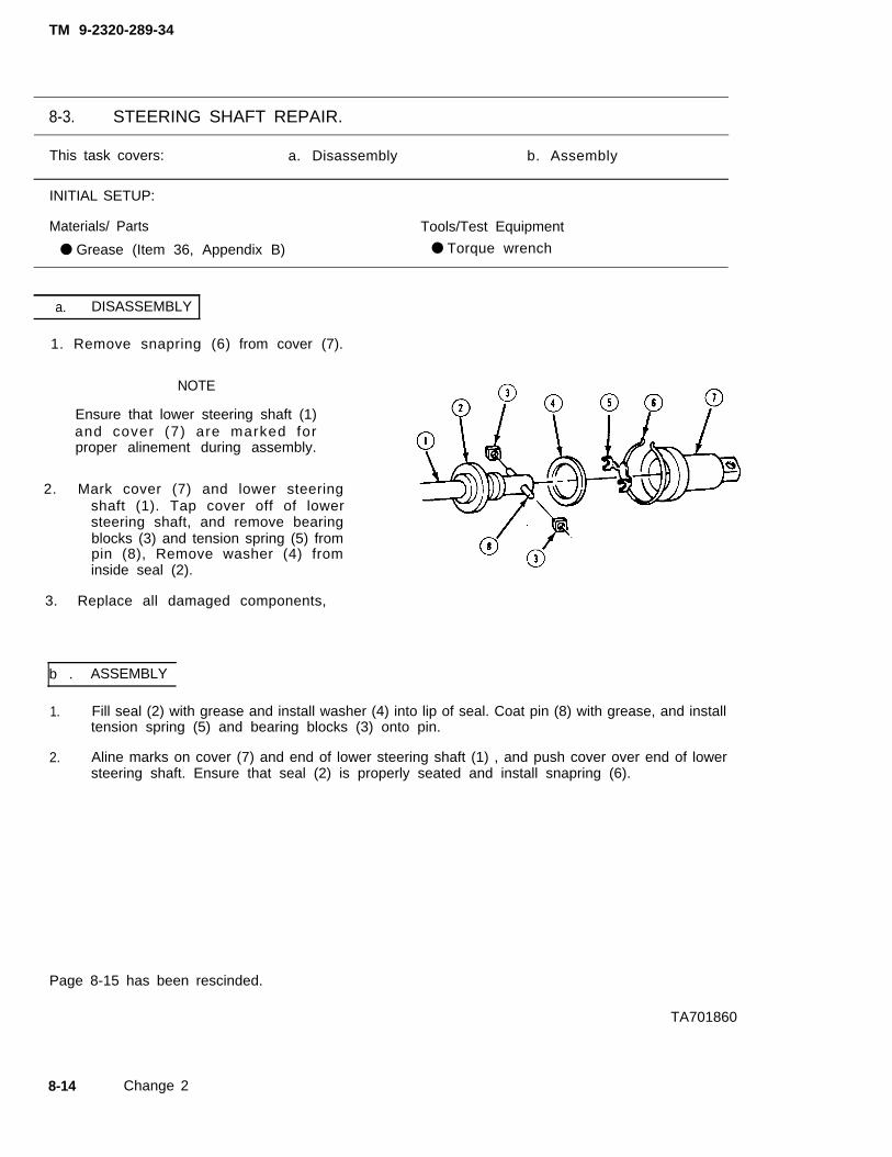
TM 9-2320-289-34
8-3. STEERING SHAFT REPAIR.
This task covers: a. Disassembly b. Assembly
INITIAL SETUP:
Materials/ Parts Tools/Test Equipment
● Grease (Item 36, Appendix B) ● Torque wrench
a. DISASSEMBLY
1. Remove snapring (6)
NOTE
from cover (7).
Ensure that lower steering shaft (1)and cover (7) are marked forproper alinement during assembly.
2. Mark cover (7) and lower steeringshaft (1). Tap cover off of lowersteering shaft, and remove bearingblocks (3) and tension spring (5) frompin (8), Remove washer (4) frominside seal (2).
3. Replace all damaged components,
b . ASSEMBLY
1. Fill seal (2) with grease and install washer (4) into lip of seal. Coat pin (8) with grease, and installtension spring (5) and bearing blocks (3) onto pin.
2. Aline marks on cover (7) and end of lower steering shaft (1) , and push cover over end of lowersteering shaft. Ensure that seal (2) is properly seated and install snapring (6).
Page 8-15 has been rescinded.
TA701860
8-14 Change 2

TM 9-2320-289-34
8-3. STEERING SHAFT MAINTENANCE (Con’t).
b. DISASSEMBLY
1. Remove snapring (13) from cover(14).
NOTE
Ensure that lower steering shaft(6) and cover (14) are marked forproper alinement during assembly.
2. Mark cover (14) and lower steeringshaft (6). Tap cover off of lowersteering shaft, and remove bearingblocks (10) and tension spring (12)from pin (15). Remove washer (11)from inside seal (9).
3. Replace all damaged components.
c . ASSEMBLY
1. Fill seal (9) with grease and install washer (11) into lip of seal. Coat pin (15) with grease, andinstall tension spring (12) and bearing blocks (10) onto pin.
2 . Aline marks on cover (14) and end of lower steering shaft (6), and push cover over end oflower steering shaft. Ensure that seal (9) is properly seated and install snapring (13).
d . INSTALLATION
1 . Lubricate end of upper shaft (5). Install lower steering shaft (6) onto upper shaft with notch incover (14) toward flat side of spline on upper shaft. Tap into place.
2 . Tap bolt into upper and lower steering shafts (5 and 6) and install nut.
3 . Install 2 nuts (4 and 7), washers (3 and 8), and flanged end of lower steering shaft (6) toflexible coupling (2) at steering gear (1). Tighten nuts to 20 Ib.-ft. (27 N.m),
TA50484
8-15

TM 9-2320-289-34
8-4. POWER STEERING GEAR REPAIR.
This task covers: a. Disassembly c. Assemblyb. Cleaning and Inspection
INITIAL SETUP:
Equipment Condition Materials/Parts
● Power steering gear removed.(See TM 9-2320-289-20)
Too/s/Test Equipment● Ball retainer tool● Rack piston installer● Snapring pliers• Spanner wrench● Torque wrench
●
●
●
●
●
●
●
●
●
One check valveOne rack piston seal ringOne side cover gasketOne stub shaft sealOne stub shaft dust sealTwo pitman shaft sealsThree teflon valve body ringsEight “O“ ringsDry cleaning solvent(Item 23, Appendix B)Grease (Item 36, Appendix B)Hydraulic fluid (Item 40, Appendix B)Petrolatum (Item 50, Appendix B)Duct tape (Item 66, Appendix B)
General Safety Instructions
● Dry cleaning solvent is flammable and must not be used near open flame. Use only in awell-ventilated area.
● Compressed air used for cleaning purposes should never exceed 30 psi (207 kPa).
a. DISASSEMBLY
1 . Remove bolt (10) securing fIexiblecoupling (9) to stub shaft (8).Remove flexible coupling.
2 . Remove adjuster locknut (2) andremove 4 bolts (3) from side cover( l ) . Turn adjuster screw (5)clockwise until side cover separatesfrom pitman shaft (6) Remove sidecover. Remove gasket (4) from sidecover, Discard gasket. Drain fluidfrom housing into a suitablecontainer.
3 . Place housing (7) assembly in asoft-jawed vise with side cover (1)opening facing up.
TA60485
8-16

TM 9-2320-289-34
8-4. POWER STEERING GEAR REPAIR.
This task covers: a. Disassembly c. Assemblyb. Cleaning and Inspection
INITIAL SETUP:
Equipment Condition Materials/Parts
● Power steering gear removed.(See TM 9-2320-289-20)
Too/s/Test Equipment● Ball retainer tool• Rack piston installer● Snapring pliers● Spanner wrench• Torque wrench
One check valveOne rack piston seal ringOne side cover gasketOne stub shaft sealOne stub shaft dust sealTwo pitman shaft sealsThree teflon valve body ringsEight “O” ringsDry cleaning solvent(Item 23, Appendix B)Grease (Item 36, Appendix B)Hydraulic fluid (Item 40, Appendix B)Petrolatum (Item 50, Appendix B)Duct tape (Item 66, Appendix B)
General Safety Instructions
● Dry cleaning solvent is flammable and must not be used near open flame. Use only in awell-ventilated area.
• Compressed air used for cleaning purposes should never exceed 30 psi (207 kPa),
a. DISASSEMBLY
1. Remove bolt (10)coupl ing (9) to
securing flexiblestub shaft (8) .
Remove flexible coupling.
2 . Remove adjuster locknut (2) andremove 4 bolts (3) from side cover(1), Turn adjuster screw (5)clockwise until side cover separatesfrom pitman shaft (6) Remove sidecover. Remove gasket (4) from sidecover. Discard gasket. Drain fluidfrom housing into a suitablecontainer.
3. Place housing (7) assembly in asoft-jawed vise with side cover (1)opening facing up.
TA50485
8-16

TM 9-2320-289-34
8-4. POWER STEERING GEAR REPAIR (Con’t).
4. Insert punch through retaining ringaccess hole (14) to force outretaining ring (11). Remove retainingring.
NOTE
• It may be necessary to useflexible coupling (9) to rotatestub shaft (8).
• It may be necessary to taparound outside of housing endplug (12) to center plug inhousing (7) during step 6.
Ro ta te s tub sha f t (8 ) coun te r -5 .clockwise and remove housing endplug (12) from housing (7).
6 . Rotate stub shaft (8) clockwise andremove “O” ring (13) and rack pistonplug (15). Discard “O” ring.
7. Rotate stub shaft (8) to center rackpiston (16). Remove pitman shaft(6) .
8 . Fully insert ball retainer tool into rackpiston (16) plug bore and hold tightlywhile turning stub shaft (8) counter-clockwise. Remove rack piston andbal l retainer tool together f romhousing (7).
TA50486
8-17

TM 9-2320-289-34
8-4. POWER STEERING GEAR REPAIR (Con’t).
NOTE
Worm gear (32) and valve assembly (34) may come(17), If so, separate adjuster plug from worm gear
9. Using punch, loosen and removelocknut (18). Using spanner wrench,remove adjuster plug (17).
out with adjuster plugand valve assembly.
10. Using a screwdriver at raised area,remove bearing retainer (19).Remove thrust bearing spacer (20),small upper bearing race (21 ), upperthrust bearing (22), large upperbearing race (23), and “O” ring (24).Discard “O” ring.
11. From rear side of adjuster plug (17), remove retaining ring (28). Press out needle bearing(25), stub shaft seal (26); and stub shaft dust seal (27). Discard seals.
TA50487
8-18

TM 9-2320-289-34
8-4. POWER STEERING GEAR REPAIR (Con’t).
12. Remove stub shaft (8), valve assembly (34), and worm gear (32) as a unit. Remove race(29), thrust bearing (30), and race (31 ). Separate valve assembly from worm gear. Remove 3teflon valve body rings and 3 “O“ rings, Discard teflon valve body rings and “O“ rings.
13. Remove valve body “O” ring (33) from valve assembly (34). Discard “O” ring.
TA50488
8-19

TM 9-2320-289-34
8-4. POWER STEERING GEAR REPAIR (Con’t).
14. Lightly tap stub shaft (8) on a woodblock to loosen shaft cap. Pull outstub shaft with spool valve (36) fromvalve assembly (34),
15. Separate spool valve (36) from stubshaft (8) and remove “O” ring fromspool valve. Discard “O” ring.
NOTE
Balls (43) will fall out. There are 12 silver and 12 black balls.
16. Remove 2 screws (40) and clamp(39) on side of rack piston (16).Remove guide (38).
17. Separate 2 halves of guide (38), andremove balls (43). Remove ballretaining tool, and tip rack piston (16)to release remaining balls from insidepiston. Remove teflon ring and “O”ring from outer groove (42) of rackpiston, and discard.
TA50489
8-20

TM 9-2320-289-34
8-4. POWER STEERING GEAR REPAIR (Con’t).
18. Using snapring pliers, remove pistonseal retaining ring (48) from bottomof housing (7). Remove outer sealbackup washer (47), and press outpitman shaft needle bearing (43),pitman shaft seal (44), inner sealbackup washer (45), and double lipseal (46) from housing assembly,Discard pitman shaft seal and doublelip seal,
CAUTION
Care should be taken not to damage threads in housing (7) whenremoving check valve (46),
19. Using a small screwdriver, pry outcheck valve (46) from top of housing(7). Discard check valve,
20. Remove housing (7) from vise.
TA50490
8-21

TM 9-2320-289-34
8-4. POWER STEERING GEAR REPAIR (Con’t).
b. CLEANING AND INSPECTION
WARNING
1.
2 .
3 .
4 .
5.
6.
7 .
8 .
l Dry cleaning solvent P-D-680 is toxic and flammable. Alwaysprotective goggles and gloves and use only in a well-ventilated
weararea.
Avoid contact with skin, eyes, and clothes and DO NOT breathe vapors.DO NOT use near open flame or excessive heat, The solvent’s flashpoint is 100°F-138°F (38°C-59°C). If you become dizzy while usingcleaning solvent, immediately get fresh air and medical help. If solventcontacts eyes, immediately wash your eyes with water and get medicalaid.
. Compressed air used for cleaning purposes should never exceed 30 psi(207 kPa). Use only effective chip guarding and personal protectiveequipment (goggIes/shield, gloves, etc.), Failure to follow this warningmay result in injury to personnel.
Clean all parts with dry cleaning solvent, Dry with compressed air.
Inspect upper pitman shaft bearing and side cover. Replace bearing if needles do not rotatefreely. Replace side cover if bearing surfaces are scored,
Inspect pitman shaft and adjuster screw for excessive wear or damage. Replace if worn ordamaged or if adjuster screw is not free to turn.
Inspect worm gear, rack piston, and all balls for wear or damage, Replace worm gear, rackpiston, and balls as an assembly if worn or damaged.
Inspect rack piston ball return guide halves for wear or damage, Replace if worn or damaged.
Inspect adjuster plug threads, spacer, races, and bearings for wear or damage. Replace ifworn or damaged.
Inspect stub shaft, spool valve, andvalve assembly for wear or damage.Replace valve assembly, spool valve,and stub shaft as an assembly if wornor damaged.
Inspect housingReplace if worn
c . ASSEMBLY
for wear or damage.or damaged.
1 . Place housing (7) in a soft-jawed visewith side cover opening facing up.
2 . Using a 3/8 in. drift punch and smallhammer, carefully tap new checkvalve (46) into housing (7).
TA50491
8-22

TM 9-2320-289-34
8-4. POWER STEERING GEAR REPAIR (Con’t).
3 . Install new “ O“ ring in outer groove (42). Install new teflon ring over top of “ O“ ring. Slideworm gear (32) completely into rack piston (1 6). Turn worm gear until worm gear groove isalined with rear ball return guide hole (41).
NOTE
Ensure that silver and black balls (43) are lubricated with hydraulic fluidand installed alternately into rack piston (16). As balls are installed andworm gear (32) is rotated, worm gear will be pushed out of rack piston.
4 . Install 18 balls (43), alternating silverballs with black balls, through rearball return guide hole (41) whilerotating worm gear (32)counterclockwise.
5. Install 6 remaining balls (43) in guide(38), alternating silver balls with blackballs, and retain with petrolatum,
6. Assemble both halves of guide (38)together. Install guide into rack piston(16) and rotate worm gear (32)clockwise until worm gear is seated inrack piston.
7. Install clamp (39) and 2 screws (40).Tighten screws to 48 lb.-in, (5 Nom).Install ball retainer tool into rackpiston (16) and remove worm gear(32). Leave ball retainer tool in rackpiston.
TA50492
8-23

TM 9-2320-289-34
8-4. POWER STEERING GEAR REPAIR (Con’t).
8.
9 .
10.
11.
NOTE
In order to assist in assembly, ensure that teflon valve body rings (35) aresoaked in warm water before assembly.
Lubricate 3 new teflon valve body rings (35) and 3 new “O” rings with hydraulic fluid and installonto valve assembly (34).
Install new “ O“ ring on spool valve (36). Lubricate spool valve and valve assembly (34) withhydraulic fluid. Install spool valve approximately 1/4 in. (6.35 mm) into valve bore.
Install stub shaft (8) into spool valve (36) so that pin on stub shaft engages upper hole in spoolvalve.
Insert stub shaft (8) and spool valve (36) into valve assembly (34) so that slot (37) on shaftcap locks with pin inside valve assembly and cap seats against shoulder.
12.
13.
Install new “O“ ring (33) into end of valve assembly (34).
Assemble race (31 ), thrust bearing (30), and race (29) on worm gear (32) with bevel on racesfacing away from drive end of worm gear.
14. Engage pin in wormworm gear as a unit
gear (32) with slotinto housing (7).
in valve assembly (34). Install valve assembly and
TA50493
8-24

TM 9-2320-289-34
8-4. POWER STEERING GEAR REPAIR (Con’t).
15.
16.
17.
With stamped identificationPlug (17). Install new “O”
end up, press needle bearing (25) 5/8 in. (15.88 mm) into adjusterring (24) on adjuster plug.
Install new stub shaft seal (26), new stub shaft dust seal (27), and retaining ring (28) onadjuster plug (17).
NOTE
Ensure that bearing retainer (19) raised areas do not extend above bearingspacer (20) when bearing retainer is seated, Bearing spacer must be freeto rotate.
Install large upper bearing race (23), upper thrust bearing (22), small upper bearing race (21),thrust bearing spacer (20), and bearing retainer (19) on adjuster plug (17).
TA50494
8-25

TM 9-2320-289-34
8-4. POWER STEERING GEAR REPAIR (Con’t).
18. Install adjuster plug (17) into housing (7), DO NOT tighten.
19. Adjust bearing preload.
(a) Using spanner wrench, tighten adjuster plug (17) clockwise until adjuster plug is firmlybottomed.
(b) Mark housing (7) and face of adjuster plug (17), Measure back counterclockwise 1/2 in.(12.7 mm) and place a second mark on housing,
TA50495
8-26

TM 9-2320-289-34
8-4. POWER STEERING GEAR REPAIR (Con’t).
(c) Turn adjuster plug (17) counter-clockwise until mark on face ofadjuster plug l ines up withsecond mark on housing (7).
(d) Hold adjuster plug (17) to maintain alinement of marks and install locknut (18). Using apunch, tighten locknut securely.
(e) Wrap stub shaft (8) splines withduct tape to provide secure fitfor 11/18 in. 12-point socket.Install socket and a lb.-in. torquewrench on stub shaft splines.While rotating stub shaft, torquewrench reading shou ld be4-8 lb.-in. (1-2 Nom). Recordtorque wrench reading for lateradjustment.
(f) If torque wrench reading in step(e) is not correct, loosen locknut(18), adjust position of adjusterplug (17) in or out as required,tighten locknut, and repeat step(e). Remove socket and torquewrench when adjustment iscorrect.
TA50496
8-27

TM 9-2320-289-34
8-4. POWER STEERING GEAR REPAIR (Con’t).
NOTE
● Ensure that seals (44 and 46), seal backup washers (45 and 47), andinner housing (7) are greased prior to installation.
● Ensure that seals (44 and 46) and seal backup washers (45 and 47) areseated just past retaining ring (48) grooves.
20. Install pitman shaft needle bearing(43) into housing (7) until bearing isfully seated. Install new pitman shaftseal (44), inner seal backup washer(45), new double lip pitman shaft seal(46), and outer seal backup washer(47) into housing. Using snapringpliers, install pitman seal retainingring (48),
21. Install rack piston (16) into rack piston installer. Install rack piston and ball retainer tool intohousing (7). Hold ball retainer tool tightly against worm gear while turning stub shaft (8)clockwise until seated. Ensure that no balls have dropped out.
22. Install rack piston plug (15), DO NOT tighten. Center rack piston (16) and install pitman shaft(6) in housing (7), Tighten rack piston plug to 75 Ib.-ft, (102 N.m),
TA50497
8-28

TM 9-2320-289-34
8-4. POWER STEERING GEAR REPAIR (Con’t).
NOTE
Ensure that opening in retainingring (11) is located approximately1 in. (25 mm) from access hole(14) when installed.
23. Install new “O“ ring (13), housing endplug (12), and retaining ring (11).
TA60498
8-29

TM 9-2320-289-34
8-4. POWER STEERING GEAR REPAIR (Con’t).
24. Install new side cover gasket (4) on side cover (1) and bend tabs around side cover edges.Install side cover onto threaded end of pitman shaft (6), and turn adjuster screw (5)counterclockwise until side cover is seated against housing (7) and adjuster screw iscompletely backed out. Install side cover bolts (3) and tighten to 40 Ib.-ft, (54 N.m). Installadjuster locknut (2),
25. Adjust pitman shaft (6) preload.
(a )
( b )
(c)
(d)
(e)
(f)
Install an 1 1/18 in. 12-point socket and a lb.-in. torque wrench on stub shaft (8) splines.Turn stub shaft clockwise until it stops. Counting number of turns, rotate stub shaftcounterclockwise until it stops. Turn stub shaft back halfway to center position.
Turn torque wrench back and forth through center of travel.
Tighten adjuster screw (5) until torque wrench reads between 6-10 lb.-in. (1-2 N.m)higher than reading recorded in step 19 (e). The total reading should not exceed 20 lb.-in.(2 N.m) torque.
Hold adjuster screw (5) in place while tightening adjuster locknut (2) to 20 Ib.-ft.(27 N.m). Recheck preload after tightening adjuster locknut.
If preload is incorrect, loosen adjuster locknut (2) and adjuster screw (5) and repeat step(c) .
Remove socket, torque wrench, and duct tape from stub shaft (8) splines afteradjustment is correct.
26. Install flexible coupling (9) to stubshaft (8) with bolt (10), Tighten boltto 30 Ib.-ft, (41 N.m).
27. Remove power steering gear fromvise.
TA50499
8-30

TM 9-2320-289-34
8-4. POWER STEERING GEAR REPAIR (Con’t).
FOLLOW-ON TASKS:
● Install power steering gear. (See TM 9-2320-289-20)
8-31

TM 9-2320-289-34
8-5. POWER STEERING PUMP REPAIR.
This task covers: a, Disassembly c. Assemblyb. Cleaning and Inspection
INITIAL SETUP:
Equipment Condition Materials/Parts
● Power steering pump, bracket, and pulley • One drive shaft sealremoved. (See TM 9-2320-289-20) ● Seven “O” rings
● Fluid drained from pump reservoir assembly. ● Dry cleaning solvent(Item 23, Appendix B)
Tools/Test Equipment ● Hydraulic fluid (Item 40,• Torque wrench
General Safety Instructions
● Dry cleaning solvent is flammable and must not be used near open flame,well-ventilated area.
• Compressed air used for cleaning purposes should never exceed 30 psi (207
Appendix B)
Use only in a
kPa).
a. DISASSEMBLY
NOTE
Ensure that location of stud (11) and bolt (9) are marked for assembly,
1. Remove stud (11) and bolt (9).
WARNING
Dry cleaning solvent P-D-680 is toxic and flammable. Always wearprotective goggles and gloves and use only in a well-ventilated area, Avoidcontact with skin, eyes, and clothes and DO NOT breathe vapors. DO NOTuse near open flame or excessive heat. The solvent’s flash point is100°F-138°F (38°C-59°C). If you become dizzy while using cleaningsolvent, immediately get fresh air and medical help. If solvent contactseyes, immediately wash your eyes with water and get medical aid.
2 . Clean exterior of power steering pump with dry cleaning solvent. Remove reservoir cap (8).
3 . Remove nut and fitting assembly (10), “O” ring (1 2), and control valve (13) and spring (14)assembly. Discard “O“ ring.
4. Place power steering pump in soft-jawed vise with jaws on pump housing (1). Remove pumphousing from pump reservoir assembly (7). Remove “O“ rings (4, 5, 6, and 15) and magnet(2). Discard “O“ rings.
8-32

TM 9-2320-289-34
8-5. POWER STEERING PUMP REPAIR (Con’t).
NOTE
If welch plug (3) at top of pump housing (1) is deformed or dislodged, DONOT remove it. Pump housing assembly will have to be replaced.
5. Insert a punch into hole in pumphousing (1) and remove retaining ring(17) from end plate (16). Removeend plate.
TA50500
8-33

TM 9-2320-289-34
8-5. POWER STEERING PUMP REPAIR (Con’t).
CAUTION
Ensure that positions of pressure plate (24) and pump ring (23) are notedfor assembly, Failure to follow this caution may result in power steeringsystem malfunction.
6. Examine end of drive shaft (18) in pump housing (1) assembly. If corroded, clean with crocuscloth before removing, If bushing is damaged, pump housing assembly will have to bereplaced.
7 . Remove pressure plate spring (25). Using a rubber mallet, lightly tap on drive shaft (18) untilpressure plate (24) is free, Remove pressure plate.
8 . Remove pump ring (23) and vanes (22) from rotor (20). Pull shaft (18), rotor, and thrust plate(19) from pump housing (1) assembly.
9 . Remove retaining ring (21) from drive shaft (18) and discard. Remove rotor (20) and thrustplate (19).
TA50501
8-34

TM 9-2320-289-34
8-5. POWER STEERING PUMP REPAIR (Con’t).
10. Remove 2 dowel pins (29) from pumpring (23). Remove drive shaft seal(26) and 2 “O” rings (27 and 28).Discard “ O“ rings,
b. CLEANING AND INSPECTION
WARNING
• Dry cleaning solvent P-D-680 is toxic and flammable. Always wearprotective goggles and gloves and use only in a well-ventilated area,Avoid contact with skin, eyes, and clothes and DO NOT breathe vapors.DO NOT use near open frame or excessive heat. The solvent’s flashpoint is 100°F-138°F (38°C-59°C). if you become dizzy while usingcleaning solvent, immediately get fresh air and medical help, if solventcontacts eyes, immediately wash your eyes with water and get medicalaid.
• Compressed air used for cleaning purposes should never exceed 30 psi(207 kPa). Use only effective chip guarding and personal protectiveequipment (goggles/shieid, gloves, etc.). Failure to follow this warningmay result in injury to personnel.
1 . Clean all parts with dry cleaning solvent, Dry with compressed air.
2 . Inspect the following rotating group components:
(a) Vanes (22) for scoring or excessive wear; and fit of vanes in rotor (20) for sticking orexcessive play.
(b) Rotor (20) slots for burrs and excessive wear at thrust faces.
(c) Inner surface of pump ring (23) for scoring or wear.
If any of these conditions exist, replace rotor, vanes, pump ring, and retaining ring (21) as anassembly.
TA50502
8-35

TM 9-2320-289-34
8-5. POWER STEERING PUMP REPAIR (Con’t).
3 . Inspect thrust plate and pressure plate for wear on plate surfaces. Replace if badly worn ordamaged.
4 . Inspect drive shaft seal for leakage or damage. Replace drive shaft seal if leaking or damaged.
5 . Inspect drive shaft for excessive burning or scoring. Replace if burned or scored.
6 . Inspect control valve, Replace control valve if it does not move freely in valve bore.
c . ASSEMBLY
NOTE
Ensure that all “O” rings and seals are lubricated with hydraulic fluidbefore assembly.
1 . Install 2 new “O“ rings (27 and 28)into grooves in pump housing (1).
2 . Using suitable socket, install newdrive shaft seal (26).
3 . Install 2 dowel pins (29) into pumphousing (1).
4 . Install thrust plate (19) on drive shaft (18) with countersunk side toward drive shaft. Install rotor(20) onto thrust plate and install new retaining ring (21 ).
5 . Install drive shaft (18) assembly in pump housing (1), indexing dowel pins (29) in pumphousing with holes in thrust plate (19).
6 . Install vanes (22) in rotor (20). Install pump ring (23) over vanes and rotor, indexing dowel pins(29) in pump housing (1) with small holes in pump ring, and recesses in thrust plate (19) withlarge holes in pump ring. Ensure that pump ring is fully seated.
7 . Install pressure plate (24) on pump ring (23) and lightly tap into place. Install pressure platespring (25).
TA50503
8-36

TM 9-2320-289-34
8-5. POWER STEERING PUMP REPAIR (Con’t).
8 . Lubricate end plate (16) withhydraulic fluid and install into pumphousing (1), Using a “C” clamp,compress end plate down in pumphousing and install end plate retainingring (17). Remove “C” clamp.
TA50504
8-37

TM 9-2320-289-34
8-5. POWER STEERING PUMP REPAIR (Con’t).
9 . Install magnet (2) into pump housing (1). Lubricate new “O” rings (4, 5, 6, and 15) withhydraulic fluid and install. Install pump reservoir assembly (7) onto pump housing (1). Installstud (11) and bolt (9) into assembly finger tight.
10. Install spring (14) and control valve (13) assembly with flat end of control valve facing outward.Install nut and fitting assembly (10) with new “ O“ ring (12) in top groove. Tighten to 35 Ib.-ft.(47 N.m). Tighten stud (11) and bolt (9) to 25 Ib.-ft. (34 N.m). Install reservoir cap (8).
FOLLOW-ON TASKS:
● Install power steering pump pulley, bracket, and pump. (See TM 9-2320-289-20
TA50505
8-38

TM 9-2320-289-34
CHAPTER 9FRAME MAINTENANCE
9-1. FRAME MAINTENANCE INDEX.
ParagraphNumber
9-2.9-3.9-4.
Procedures
General . . . . . . . . . . . . . . . . . . . . . . . . . . . . . . . . . . . . . .Frame Measurement . . . . . . . . . . . . . . . . . . . . . . . . . . . . . . . . .Frame Repair . . . . . . . . . . . . . . . . . . . . . . . . . . . . . . . . . . . .
PageNumber
9-29-39-7
9-1

TM 9-2320-289-34
9-2. GENERAL.
a. General frame maintenance procedures can be found in TB 9-2300-257-40. Referencesto 3/4 ton and 1 1/4 ton truck apply to CUCV Series trucks.
b. Perform FRAME MEASUREMENT in paragraph 9-3 to determine if any adjustments needto be made to f fame dimensions.
c. Perform FRAME REPAIR in paragraph 9-4 to repair any defects discovered in frameassembly.
9-2

TM 9-2320-289-34
9-3. FRAME MEASUREMENT.
This task covers: a. Frame Inspection b. Frame Measurement
INITIAL SETUP:
Equipment Condition Tools/Test Equipment
● Truck parked on level surface in ● Datum gageswell-lighted area. ● Steel tape measure
● Tram gage
Personnel Required
● MOS 44B (1)
a. FRAME INSPECTION
1. Inspect suspension and axle components for looseness, improper alinement, and damage.Tighten, realine, or replace components as needed.
b. FRAME MEASUREMENT
●
●
●
●
NOTE
Ensure that frame is measured along all lines shown on Illustrations onpages 9-4 and 9-5. The following procedure should be used whenperforming these measurements.
A tolerance of plus or minus (±) 0.12 in (3 mm) Is acceptable onframe measurements unless otherwise stated.
Bolts, nuts, studs, and nonremovable plugs are shown on illustrationsas solid objects. Holes are shown as outlines.
Ensure that any drivetrain, exhaust, or suspension components areremoved as required to obtain direct point-to-point measurements.
1. Measure all bolts, nuts, studs, and nonremovable plugs from center-to-center.
2 . On bottom view illustrations, measurement points at a 90 degree angle to centerline should be an equal distance from centerline, ± 0.12 in. (± 3 mm). Diagonal measurementsshould be the same, ±0.19 in. (±5 mm), and should cross at centerline.
NOTE
The datum line is an imaginary line parallel to floor at lowest point onframe.
3 . Measure all dimensions on side view illustrations from center-to-center. Attach datum gages atpoints on frame to be measured. Measure all length dimensions parallel to datum line.Measure all height dimensions at a 90 degree angle to datum line.
9 - 3

TM
9
-23
20
-28
9-3
4
9-3
.F
RA
ME
ME
AS
UR
EM
EN
T (C
on’t).
9-4

TM
9-2320-289-34
9-3
.F
RA
ME
ME
AS
UR
EM
EN
T (C
on’t).
9-
5

TM 9-2320-289-34
9-3. FRAME MEASUREMENT (Con’t).
4. Unless otherwise stated, all holes are measured from their closest edge to the other point ofreference. Holes shown with (centerline) symbol beside them are measured from center ofhole. Add 1/2 of hole diameter to dimension if measuring from centerline of a hole.
5. Perform applicable frame repair procedure in paragraph 9-4 to bring dimensions withinspecifications.
9 - 8

TM 9-2320-289-34
9-4. FRAME REPAIR.
This task covers: a. Frame Repair Guidelines d. Frame Reinforcementb. Loose Rivet Replacement e. Crack Repairc. Damaged Bracket f. Frame Straightening
Replacement
INITIAL SETUP:
Equipment Condition Materials/Parts
● Frame dimensions measured and ● Bolts (as needed)recorded. (See paragraph 9-3) ● Lockwashers (as needed)
● Nuts (as needed)
Tools/Test Equipment Manual References
● River buster ● TB 9-2300-257-40● Torch with rosebud heating tip ● TM 9-237
Personnel Required
● MOS 44B (1)
a . FRAME REPAIR GUIDELINES
1.
2 .
3 .
4 .
5 .
6.
7 .
8.
9 .
NOTE
Ensure that all FRAME REPAIR GUIDELINES are followed when attemptingto repair any frame components.
Remove any drivetrain, exhaust, and suspension components as required to obtain directaccess to any damaged rivet, bracket, hanger, or support.
Avoid changing frame thickness.
Avoid drilling holes in frame rail flanges.
Space holes in web section of rail at least 0.5 in. (13 mm) from one another.
Use existing holes whenever possible,
DO NOT cut holes with a torch,
Avoid welding on flanges.
DO NOT allow 4 or more holes to exist on same
Holes made in a reinforcement should be placededge of reinforcement.
vertical line of web.
at least 2 times the material thickness from
9 - 7

TM 9-2320-289-34
9-4. FRAME REPAIR (Con’t).
b. LOOSE RIVET REPLACEMENT
Use only effective chip(goggles/shield, gloves,
WARNING
guarding and personnel protective equipmentetc.) when using drill. Failure to follow this
warning may result in injury to personnel,
CAUTION
l
l
l
Welding is not an approved or acceptable alternate method of repair forany rivet attachment on frame. Only use the following procedure,Failure to follow this caution may result in damage to frame assembly.
Use only SAE Grade 8 bolts and nuts to replace rivets. Failure to followthis caution may result in weak frame attachments.
Rivets should be removed with rivet buster (NSN 5100-00-293-0556).DO NOT use an ordinary chisel for this purpose. Failure to follow thiscaution will elongate rivet hole and cause any future bolting to beseriously weakened.
NOTE
When bolt is used to replace rivet on top or bottom flange of side rail, boltmust be installed from top down.
1 . Remove rivet by shearing rivet head with rivet buster. Remove rest of rivet body from rivet holeusing drift punch and hammer.
2 . Using appropriate electric drill and 7/16 in. drill bit, drill out existing hole.
3 . Install a 7/16 in. -14 appropriate length hex head bolt, 7/16 in. “HEAVY” classification Iockwasher,and 7/16 in. hex nut.
4 . Tighten hex nut to 55-65 lb. -ft. (75-88 N.m).
c . DAMAGED BRACKET REPLACEMENT
WARNING
Use only effective chip guarding and personnel protective equipment(goggles/shield, gloves, etc.) when using drill.warning may result in injury to personnel.
●
●
CAUTION
Use only SAE Grade 8 bolts and nuts to replace
Failure to follow this
rivets. Failure to followthis caution may result in weak frame attachments.
Rivets should be removed with rivet buster (NSN 5100-00-293-0556),DO NOT use an ordinary chisel for this purpose. Failure to follow thiscaution will elongate rivet hole and cause any future bolting to beseriously weakened.
9-8

TM 9-2320-289-34
9-4. FRAME REPAIR (Con’t).
●
●
●
NOTE
The following procedure may be used to replace any bracket, hanger,or support that attaches to frame.
Ensure that any drivetrain, exhaust, and suspension componentsrequired to obtain direct access to any damaged bracket, hanger, orsupport are removed.
When bolt is used to replace rivet on top or bottom flange of side rail,bolt must be installed from top down,
1 . Remove rivet by shearing rivet head with rivet buster. Remove rest of rivet body fromusing drift punch and hammer.
rivet hole
2 . Install a 3/8 in. appropriate length hex head bolt, 3/8 in. “HEAVY” classification Iockwasher, and3/8 in. hex nut,
3 . Tighten each nut to 30-40 Ib.-ft. (41-54 N.m).
d. FRAME REINFORCEMENT
1 . See TB 9-2300-257-40.
e. CRACK REPAIR
WARNING
Use only effective chip guarding and personnel protective equipment(goggles/shield, gloves, etc.) when using grinder. Failure to follow thiswarning may result in injury to personnel.
CAUTION
DO NOT use oxyacetylene welding equipment to repair cracks on CUCVSeries truck frames. Failure to follow this caution may result in weldand/or frame failures.
NOTE
● Straight cracks may result from high concentrations of stress in smallareas of frame, excessive bending movement, and torsional loading.
● Sunburst cracks are caused by high loads being applied to a mountingbracket or crossmember which is not securely or properly attached torail,
● Crossmember mounting flange cracks may be repaired in the samemanner as side rail cracks; however, ensure that weld bead is built upto provide a good, smooth radius.
1 . Remove any component that will interfere with access to crack.
9-9

TM 9-2320-289-34
9-4. FRAME REPAIR (Con’t).
2 . Locate extreme end of crack and drill a 0.25 in. (6 mm) hole.
3 . “V” grind entire length of crack from starting point to 0.25 in. (6 mm) hole at extreme end.
4 . Using a hacksaw blade, open up bottom of crack 0.062 in. (2 mm) to allow good penetrationof weld.
5 . Weld crack in accordance with TM 9-237,
6 . Grind weld smooth on both inside and outside of rail or crossmember. Eliminate all weldbuildup or notches on edge of flange.
7 . Install reinforcements as outlined in TB 9-2300-247-40 as required.
f . FRAME STRAIGHTENING
CAUTION
● Frame straightening can be complicated and usually requires specialequipment. Only experienced personnel should attempt this procedure.
● DO NOT heat frame any hotter than 1200°F (606°C) when straighteningframe. A red glow indicates that material is overheated. Use ofexcessive heat may weaken strength and durability of frame.
NOTE
Most frame straightening operations can be accomplished without use ofheat. Cold straightening procedures are recommended for repair of CUCVSeries truck frames. The following procedure may be used when coldstraightening techniques are not effective.
1. Apply pressure, to area to be straightened, until slight checking (silvery cracks) appear onsurface of metal. Begin heating at this point, using torch with rosebud heating tip. Graduallyincrease pressure while heating until frame is straightened.
9-10

TM 9-2320-289-34
CHAPTER 10BODY AND ACCESSORIES MAINTENANCE
Section 1. STANDARD BODY MAINTENANCE
10-1. STANDARD BODY MAINTENANCE INDEX.
Paragraph PageNumber Procedures Number
10-2. Radiator Support Assembly Replacement . . . . .. . . . . . . . . . . . . . 10-2
10-4. Windshield and M1009 Top Assembly Side WindowReplacement . . . . . . . . . . . . . . . . . . . . . . . . . . . . . . . . . .. . . . . . . 10-10
10-5. Fender Replacement . . . . . . . . . . . . . . . . . . . . . . . .. . . . . . . . . . 10-1510-6. Wheel House Panel and Splash Guard Replacement . . . . . . . . . . . 10-21
Change 2 10-1

TM 9-2320-289-34
10-2. RADIATOR SUPPORT ASSEMBLY REPLACEMENT.
This task covers: a . R e m o v a l b. Installation
INITIAL SETUP:
Equipment Condition Tools/Test Equipment
●
●
●
●
●
●
●
●
●
●
●
●
Cooling system drained, ● Torque wrench(See TM 9-2320-289-20)Coolant recovery reservoir and upper Personnel Requiredmounting bracket removed. ● MOS 63W (2)(See TM 9-2320-289-20)Radiator removed. (See TM 9-2320-289-20) General Safety InstructionsFront battery hold-down bracket removed, • Use caution when handling sheet(See TM 9-2320-289-20) metal.Hood latch removed.(See TM 9-2320-289-20)Headlight assemblies removed.(See TM 9-2320-289-20)Parking lights removed.(See TM 9-2320-289-20)Radiator grille and front end panel moldingremoved, (See TM 9-2320-289-20)Blackout drive light and mounting bracketremoved. (See TM 9-2320-289-20)Blackout marker lights disconnected.(See TM 9-2320-289-20)Slave receptacle removed.(See TM 9-2320-289-20)Horn removed, (See TM 9-2320-289-20)
a. REMOVAL
WARNING
Use caution when handling sheet metal. Sheet metal has numerous sharpedges and splinters. Failure to follow this caution may result in injury topersonnel.
NOTE
If removing front end panel (4) and support (5), perform step 1.
1 . Remove 3 bolts (2) securing front end panel (4) and support (5) to radiator support assembly(1), Remove 4 bolts (3) securing front end panel to 2 fenders. Remove front end panel andsupport.
1 0 - 2

TM 9-2320-289-34
10-2. RADIATOR SUPPORT ASSEMBLY REPLACEMENT (Con’t).
NOTE
Ensure that location of front wiring harness is noted and all leads taggedfor installation.
2 . Disconnect front wiring harness ground wire from radiator support assembly (1) and fromframe. Disconnect front wiring harness clips from radiator support assembly. Pull front wiringharness through radiator support assembly into engine compartment,
TA50389
10-3

TM 9-2320-289-34
10-2. RADIATOR SUPPORT ASSEMBLY REPLACEMENT (Con’t).
3 . Remove 10 bolts (6) securing sides of radiator support assembly (1) to 2 fenders (7). Remove6 bolts (11) securing bottom of radiator support assembly to 2 fender skirts (9).
4 . Remove weight classification marker from bumper. At each radiator support bracket (15)remove nut (18), retainer (17), lower cushion body (16), bolt (12), and washer (13),
NOTE
Fender bolts (8 and 10) are loosened in step 5 to permit easier alinementof fender to radiator support assembly bolt holes during installation.
5. At each fender (7), loosen 7 fender-to-fender skirt bolts (10). Loosen fender-to-cowl bolt (8),
6. Pull front of fenders (7) outward just enough to raise radiator support assembly (1) from truck.Remove radiator support assembly.
TA50390
10-4

TM 9-2320-289-34
10-2. RADIATOR SUPPORT ASSEMBLY REPLACEMENT (Con’t).
7 . If damaged, remove coolant recoveryreservoir bracket from bottom left ofradiator support assembly (1). Ifdamaged, remove 2 upper cushionbodies (14) from radiator supportbrackets (15).
8 . If installing new radiator supportassembly (1), remove all attachinghardware f rom radiator supportassembly,
b. INSTALLATION
WARNING
Use caution when handling sheetmetal, Sheet metal has numeroussharp edges and splinters. Failureto follow this caution may result ininjury to personnel.
NOTE
if installing front end panel andsupport, perform step 7.
1. If removed, install coolant recovery reservoir bracket to bottom left of radiator supportassembly (1). If removed, install all attaching hardware to radiator support assembly. Ifremoved, install 2 upper cushion bodies (14) to radiator support brackets (15).
2 . Position radiator support assembly (1) in truck while pulling outward on front of fenders (7) togain clearance. At each radiator support bracket (15) loosely install washer (13), bolt (12),lower cushion body (16), retainer (17), and nut (18).
NOTE
If truck is equipped with winterization kits, it may be necessary to raisefenders (7) using a suitable jack and wooden block, to aid in alinement.
3 . Loosely install 10 bolts (6) securing sides of radiator support assembly (1) to 2 fenders (7).Loosely install 6 bolts (11) securing bottom of radiator support assembly to 2 fender skirts (9).Fully tighten bolts (6 and 11).
4 . At each fender (7), tighten 7 fender-to-fender skirt bolts (10). Tighten bolt (8) to 35 Ib.-ft.(47 N.m).
TA50391
10-5

TM 9-2320-289-34
10-2. RADIATOR SUPPORT ASSEMBLY REPLACEMENT (Con’t).
5 .
6 .
Tighten 2 nuts (18) to 35 Ib.-ft.(47 Nom),
Route front wiring harness throughradiator support assembly (1) ,Connect front wiring harness groundwire to radiator support assembly andto f rame. Connect front wiringharness clips to radiator supportassembly.
7 . Install front end panel (4) and support (5) to radiator support assembly (1) with 3 bolts (2).Install 4 bolts (3) from front end panel to 2 fenders.
8 . Install weight classification marker to bumper.
TA50392
10-6

TM 9-2320-289-34
10-2. RADIATOR SUPPORT ASSEMBLY REPLACEMENT (Con’t).
FOLLOW-ON TASKS:
● Install horn. (See TM 9-2320-289-20)● Install slave receptacle, (See TM 9-2320-289-20)● Connect blackout marker Iights, (See TM 9-2320-289-20)● Install● Install● Install● Install● Install● Install● Install● Install
blackout drive light and mounting bracket. (See TM 9-2320-289-20)radiator grille and front end panel molding. (See TM 9-2320-289-20)parking lights. (See TM 9-2320-289-20)headlight assemblies. (See TM 9-2320-289-20)hood latch. (See TM 9-2320-289-20)front battery hold-down bracket. (See TM 9-2320-289-20)radiator. (See TM 9-2320-289-20)upper mounting bracket and coolant recovery reservoir. (See TM 9-2320-289-20)
Pages 10-8 and 10-9 have been rescinded.
TA50393
Change 2 10-7/ (10-8 blank)

TM 9-2320-289-34
10-3. INSTRUMENT PAD REPLACEMENT (Con’t).
3. If removed, install reinforcement (4) to instrument pad assembly (1) with 4 washers (2) andscrews (3).
FOLLOW-ON TASKS:
● Install heater control panel and housing if removed. (See TM 9-2320-289-20)
TA50395
10-9

TM 9-2320-289-34
10-4. WINDSHIELD AND M1009 TOP ASSEMBLY SIDE WINDOW REPLACEMENT.
This task covers: a. Removal c. Installationb. Inspection
INITIAL SETUP:
Equipment Condition
● Windshield wiper arms removed (if removingwindshield). (See TM 9-2320-289-20)
Tools/Test Equipment
● Installing tool, J-26471
Manual References
● FM 43-2
Materials/Parts
• One inside rearview mirror support• Loctite adhesive (Item 5, Appendix B)● Denatured alcohol (Item 6, Appendix B)● Abrasive cloth (Item 17, Appendix B)● Masking tape (Item 68, Appendix B)
Personnel Required
● MOS 63W (2)
General Safety Instructions
● Wear heavy gloves and safety goggleswhen handling glass.
● Alcohol used in this procedure is highlyflammable and poisonous.
a . REMOVAL
WARNING
Wear heavy gloves and safety goggles when handling windshield (3) orwindow glass to avoid risk of injury to personnel.
NOTE
● If removing windshield (3), perform steps 1-3.
● If removing M1009 top assembly side window (5), perform steps 2and 3.
1. Remove inside rearview mirror (7).
2. Using tape, mark location on cab of cap (8) at bottom center of reveal molding (1). Removecap and remove reveal molding.
10-10

TM 9-2320-289-34
10-4. WINDSHIELD AND M1009 TOP ASSEMBLY SIDE WINDOW REPLACEMENT.
This task covers: a. Removal c. Installationb. Inspection
INITIAL SETUP:
Equipment Condition Materials/Parts
● Windshield wiper arms removed (if removing ● one inside rearview mirror supportwindshield). (See TM 9-2320-289-20) ● Loctite adhesive (Item 5, Appendix B)
● Denatured alcohol (Item 6, Appendix B)● Abrasive cloth (Item 17, Appendix B)● Masking tape (Item 68,
Too/s/Test Equipment Personnel Required
● Installing tool, J-26471 ● MOS 63W (2)
Manual References General Safety Instructions
● FM 43-2 ● Wear heavy gloves andwhen handling glass,
Appendix B)
safety goggles
● Alcohol used in this procedure is highlyflammable and poisonous,
a . REMOVAL
WARNING
Wear heavy gloves and safety goggles when handling windshield (3) orwindow glass to avoid risk of injury to personnel.
NOTE
● If removing windshield (3), perform steps 1-3.
● If removing M1009 top assembly side window (5), perform steps 2 and 3.
1. Remove inside rearview mirror (7),
2 . Using tape, mark location on cab of cap (8) at bottom center of reveal molding (1). Remove capand remove reveal molding.
10-10

TM 9-2320-289-34
10-4. WINDSHIELD AND M1009 TOP ASSEMBLY SIDE WINDOW REPLACEMENT(Con’t).
3 . Support windshield (3) or side window(5) from outside truck. From insidetruck, have an assistant apply firm,control led pressure to edge ofwindshield or side window. Forceweatherstrip (2) from flange (4) witha flat-bladed tool. Remove windshieldor side window and weatherstrip.Remove weatherstrip.
10-11

TM 9-2320-289-34
10-4. WINDSHIELD AND M1009 TOP ASSEMBLY SIDE WINDOW REPLACEMENT(Con’t).
b. INSPECTION
CAUTION
In event of a stress crack or leakage, ensure that weatherstrip (2) andflange (4) are thoroughly inspected before installing windshield (3).Failure to follow this caution may result in recurrence of crack or leakage.
NOTE
If sheet metal and paint repairs are needed, see FM 43-2.
1. Inspect flange for high spots or other irregularities, Remove all highbefore proceeding.
2 . Inspect weatherstrip for damage. Replace weatherstrip if damaged,
spots or irregularities
3 . Inspect replacement windshield to ensure that there are no chipped edges or otherirregularities. Obtain another windshield if repairs cannot be made.
c . INSTALLATION
WARNING
Wear heavy gloves and safety goggles whenwindow glass to avoid risk of injury.
● If installing windshield
● If installing M1009 top
NOTE
handling windshield (3) or
(3), perform steps 1-9.
assembly side window (5), perform steps 1-3.
1 . Install weatherstrip (2) to windshield(3) or side window (5).
2 . Position windshield (3) or side window(5) with weatherstrip” (2) at opening.Install weatherstrip to flange (4) alongbottom edge of opening. Workremaining edges of weatherstrip intoflange.
10-12

TM 9-2320-289-34
10-4. WINDSHIELD AND M1009 TOP ASSEMBLY SIDE WINDOW REPLACEMENT(Con’t).
3 . Apply soapy water to reveal molding (1) channel in weatherstrip (2) to serve as lubricant.Using installing tool, install reveal molding so that gap for cap (8) is positioned where marked.Install cap.
4 . Using old windshield as a guide, mark outside of windshield (3) with tape for location of support(6) for inside rearview mirror (7).
WARNING
Alcohol used in this procedure is highly flammable and poisonous.Drinking of this alcohol can cause blindness and death, Avoid inhaling itsfumes. Keep away from open flame.
5 . Using an alcohol-saturated rag, clean inside of windshield (3) where support (6) is to beinstalled.
TA50398
10-13

TM 9-2320-289-34
10-4. WINDSHIELD AND M1009 TOP ASSEMBLY SIDE WINDOW REPLACEMENT(Con’t).
6 . Using fine abrasive cloth, sand bonding surface of support (6). Clean sanded surface with analcohol-saturated rag and allow to dry.
7 . Follow directions on manufacturer’s adhesive to properly prepare support (6) prior toinstallation on windshield (3). Install support, to location marked with tape, and press againstglass for 30-60 seconds exerting steady pressure.
8 . After 5 minutes, remove any excess adhesive with an alcohol-saturated rag.
9 . Install inside rearview mirror (7).
FOLLOW-ON TASKS:
• Install windshield wiper arms. (See TM 9-2320-289-20)
TA50399
10-14

TM 9-2320-289-34
10-5. FENDER REPLACEMENT.
This task covers: a . R e m o v a l b. Installation
INITIAL SETUP:
Equipment Condition Tools/Test Equipment
Hood and hinge spring assemblies removed.(See TM 9-2320-289-20)Left or right headlight assembly removed,(See TM 9-2320-289-20)Front end panel molding removed.(See TM 9-2320-289-20)Left or right marker light removed.(See TM 9-2320-289-20)Windshield washer solvent containerremoved (left side). (See TM 9-2320-289-20)Battery supports removed from fender(right side). (See TM 9-2320-289-20)Batteries removed (right side),(See TM 9-2320-289-20)Current/voltage regulator removed (left side,Ml 01 O). (See paragraph 4-4)Heater fuel pump removed (left side, Ml 010and trucks equipped with winterization kits).(See TM 9-2320-289-20)
● Torque wrench
Personnel Required● MOS 63W (2)
Manual References● TB 43-0209
General Safety instructions● Use caution when handling sheet
metal.
a. REMOVAL
WARNING
Use caution when handling sheet metal. Sheet metal has numerous sharpedges and splinters, Failure to follow this caution may result in injury topersonnel.
10-15

TM 9-2320-289-34
10-5. FENDER REPLACEMENT (Con’t).
1 . Disconnect wiring from fender (4) and remove 2 hood bumpers (10).
2 . Remove 2 bolts (17) securing front end panel (16) to fender (4). Remove 7 bolts (15) securingfender wheel opening flange to wheel house panel (14). Remove 5 bolts (19) securing radiatorsupport assembly (18) to fender.
3 . Remove 2 screws (12) and 2 retainers, and remove shield (13).
4 . Removesecuring
NOTE
Ensure that location of shims (5) is noted for installation.
bolt (9) and shim (s) (5) at lower end of fender (4). Remove bolt (6) and shim(s)fender to cowl (1).
NOTE
An assistant is required to perform step 5.
5 . Open door and remove bolt (8) and shim (s) (5) at door hinge pillar (7). Raise rear of fender(4) and remove,
6. If damaged or if replacing fender (4), remove 7 nuts (11) from fender flange.
7 . If damaged, remove 4 screws (3) and seal (2) from cowl (1).
b . INSTALLATION
WARNING
Use caution when handling sheetmetal, Sheet metal has numeroussharp edges and splinters. Failureto follow this caution may result ininjury to personnel.
1 . If removed, install seal (2) to cowl (1)with 4 screws (3).
TA50400
10-16

TM 9-2320-289-34
10-5. FENDER REPLACEMENT (Con’t).
10-17

TM 9-2320-289-34
10-5. FENDER REPLACEMENT (Con’t).
2 .
3 .
4 .
5 .
6 .
7 .
8 .
9 .
If removed, install 7 nuts (11) to fender (4) flange.
NOTE
● An assistant is required to perform steps 3-5.
• Shims (5) should be used as required to aline fender (4).
Position fender (4) and loosely install fender to door hinge pillar (7) with bolt (8) and shim(s)(5), Loosely install fender to cowl (1) with bolt (6) and shim(s). Loosely install bolt (9) andshim(s) at lower end of fender.
Loosely install 5 bolts (19) securing radiator support assembly (18) to fender (4). Looselyinstall 2 bolts (1 7) securing front end panel (16) to fender. Loosely install 7 bolts (15) securingfender wheel opening flange to wheel house panel (14).
Aline fender (4) with door, hood, and windshield, adding or removing shims (5) as required,
Tighten 3 bolts (6, 8, and 9) to 30 Ib.-ft. (41 N.m). Tighten all other bolts (15, 17, and 19).
Install shield (13) with 2 retainers and 2 screws (12).
Connect wiring to fender (4) and install 2 hood bumpers (10)
Apply paint to fender (4) as required. (See TB 43-0209)
10-18

TM 9-2320-289-34
10-5. FENDER REPLACEMENT (Con’t).
10-19

TM 9-2320-289-34
10-5. FENDER REPLACEMENT (Con’t).
FOLLOW-ON TASKS:
● Install● Install● Install● Install● Install● Install● Install● Install● Install
heater fuel pump if removed. (See TM 9-2320-289-20)current/voltage regulator if removed, (See paragraph 4-4)batteries if removed, (See TM 9-2320-289-20)battery supports to fender if removed. (See TM 9-2320-289-20)windshield washer solvent container if removed. (See TM 9-2320-289-20)left or right marker light. (See TM 9-2320-289-20)front end panel molding, (See TM 9-2320-289-20)left or right headlight assembly. (See TM 9-2320-289-20)hood and hinge spring assemblies. (See TM 9-2320-289-20)
10-20

TM 9-2320-289-34
10-6. WHEEL HOUSE PANEL AND SPLASH GUARD REPLACEMENT.
This task covers: a. Removal b. Installation
INITIAL SETUP:
Equipment Condition Manual ReferencesHood latch cable and engine oil cooler hoses ● TM 9-2320-289-20disconnected from wheel house panel (leftside). (See TM 9-2320-289-20) General Safety InstructionsBattery cables and heater assembly hoses • Use caution when handling sheetdisconnected from wheel house panel (right metal.side). (See TM 9-2320-289-20)Battery trays and supports removed (rightside). (See TM 9-2320-289-20)Engine coolant heater removed (if truckis equipped with winterization kits, left side).(See TM 9-2320-289-20)Cab heater removed (if truck isequipped with winterization kits, right side).(See TM 9-2320-289-20)
a . REMOVAL
WARNING
Use caution when handling sheet metal. Sheet metal has numerous sharpedges and splinters. Failure to follow this caution may result in injury topersonnel.
NOTE
If removing splash guard (2), perform step 2.
1. If removing left wheel house panel (1), remove service parts identification label and save forreference.
TA50403
10-21

TM 9-2320-289-34
10-6. WHEEL HOUSE PANEL AND SPLASH GUARD REPLACEMENT (Con’t).
2 . Remove 7 retainers (3) and remove splash guard (2) from wheel house panel (1).
3. Remove 7 bolts (9) securing wheel house panel (1) to fender (5) flange. Remove 2 screws (7)securing wheel house panel to shield (8). Remove 2 bolts (4 and 6) securing wheel housepanel to bulkhead.
4 . Remove 3 bolts (10) securing wheel house panel (1) to radiator support assembly (11),
5 . Slide wheel house panel (1) forward to clear lower back side of fenderwell. Remove wheelhouse panel from truck.
b. INSTALLATION
WARNING
Use caution when handling sheet metal. Sheet metal has numerous sharpedges and splinters. Failure to follow this caution may result in injury topersonnel.
NOTE
If installing splash guard (2), perform step 5.
1 . Position wheel house panel (1) in truck and loosely install 7 bolts (9) securing wheel housepanel to fender (5) flange. Loosely install shield (8) to wheel house panel with 2 screws (7).
2 . Loosely install 3 bolts (10) securing wheel house panel (1) to radiator support assembly (11).
3 . Loosely install 2 bolts (4 and 6) securing wheel house panel (1) to bulkhead.
TA50404
10-22

TM 9-2320-289-34
10-6. WHEEL HOUSE PANEL AND SPLASH GUARD REPLACEMENT (Con’t).
4 . Tighten bolt (6) to 35 Ib.-ft. (47 N.m). Tighten bolts (4, 9, and 10) and screw (7).
5. Install splash guard (2) to wheel house panel (1) with 7 retainers (3).
FOLLOW-ON TASKS:
● Install cab heater if removed, (See TM 9-2320-289-20)● Install engine coolant heater if removed, (See TM 9-2320-289-20)● Install battery trays and supports if removed. (See TM 9-2320-289-20)• Connect battery cables and heater assembly hoses to wheel house panel if removed. (See
TM 9-2320-289-20)• Connect hood latch cable and engine cooler hoses to wheel house panel if removed. (See
TM 9-2320-289-20)
TA50405
10-23/(10-24 blank)

TM 9-2320-289-34
Section IL STANDARD BODY ACCESSORIES MAINTENANCE
10-7. STANDARD BODY ACCESSORIES MAINTENANCE INDEX.
ParagraphNumber
10-8.10-9.
Procedures
Windshield Wiper Motor Repair . . . . . . . . . . . . . . . . . . . . . . . .Cab Heater Defroster Duct Replacement . . . . . . . . . . . . . . . . .
PageNumber
10-2610-33
10-25

TM 9-2320-289-34
10-8. WINDSHIELD WIPER MOTOR REPAIR.
This task covers: a, Disassembly b. Assembly
INITIAL SETUP:
Equipment Condition Materials/Parts
● Windshield wiper motor removed. ● End cap kit(See TM 9-2320-289-20) • One gasket
● Two seals● Lubricating oil (Item 49, Appendix B)● Petrolatum (Item 50, Appendix B)
a . DISASSEMBLY
NOTE
● If disassembling armature (2) and endsteps 1-3.
● If disassembling crank arm (8) assembly,
● If disassembling washer pump assembly,
cap assembly (7), perform
perform step 4.
perform steps 5-11.
1 . Straighten 4 retainer tabs and remove end cap assembly (7). Remove felt washer (4) frominside end cap assembly.
TA50406
10-26

TM 9-2320-289-34
10-8. WINDSHIELD WIPER MOTOR REPAIR (Con’t).
2 . Rotate crank arm (8) clockwise to help free armature (2), Remove armature from housing (1),Using a magnet, remove thrust ball (3) from end of armature.
3 . Using a magnet, remove thrust plate (5) and motor thrust disc (6) from end cap assembly (7).
CAUTION
Ensure that crank arm (8) and crank arm shaft are marked for assembly,Failure to follow this caution may result in damage to, or malfunction of,wiper system.
NOTE
Before disassembling crank arm (8), ensure that windshield wiper motor isin “park” with crank arm positioned on shaft as shown.
4 . Mark crank arm (8) and crank arm shaft for assembly.Remove seal (10) and spacer (11). Discard seal.
NOTE
Remove nut (9) and remove crank arm.
Location of pawl spring (14) may vary with windshield wiper motor model.Ensure that location is noted for assembly.
5 . Remove washer pump cover. Remove pawl spring (14).
TA50407
10-27

TM 9-2320-289-34
10-8. WINDSHIELD WIPER MOTOR REPAIR (Con’t).
6 . Push in retainer tab and remove washer solenoid and park switch assembly (1 3).
7 . Remove retainer ring (15) and pawl (16) from shaft (17).
8 . Remove screw (21) and dog spring (20) from washer frame.
9 . Move leg of retainer spring (19) out of shaft (12) groove. Remove ratchetshaft.
gear (18) from
10. Pull piston housing (25) away from washer frame (26) until mounting grooves clear frame.Remove valve assembly (24), piston housing, and piston actuator plate (27) as a unit.
11. Remove 4 screws (22) and cover (23) from valve assembly (24). Remove gasket frombetween cover and valve assembly. Remove pump seal. Discard gasket and pump seal.
b. ASSEMBLY
NOTE
● If assembling washer pump assembly, perform steps 1-5.
● If assembling crank arm assembly, perform step 6.
● If assembling armature and end cap assembly, perform steps 7-11.
1. Install new pump seal in piston housing (25) grooves. Install new gasket between valveassembly (24) and cover (23). Aline valve and cover assembly with piston housing and start 4screws (22). Tighten 4 screws to evenly draw in cover.
TA50408
10-28

TM 9-2320-289-34
10-8. WINDSHIELD WIPER MOTOR REPAIR (Con’t).
2. Position piston housing (25) and valveassembly (24) with shafts (12 and 17)through slots in piston actuator plate(27). Pull back on piston housing andengage mounting grooves of pistonhousing in washer frame (26), Atshaft (1 2), apply a liberal coat ofpetrolatum between piston actuatorplate and washer frame.
3 . Depress retainer spring (19) and install ratchet gear (18) on shaft (12). Rotate ratchet gear toseat it. Install retainer spring with leg in shaft groove.
4 . Install screw (21) and dog spring (20).
5 . Install pawl (16) on shaft (17) with retainer ring (15). Install washer solenoid and park switchassembly (13), and press in on retainer tab to seat, Pull retainer tab to locking position. Installpawl spring (14) in original position. Install washer pump cover, indexing washer solenoidterminals and park switch connector with slots in cover. Snap washer pump cover to fully seat.
NOTE
Ensure that flat side of seal (10 istoward crank arm (8),
6 . Install spacer (11), new seal (10),and crank arm (8), as marked, withnut (9).
TA50409
10-29

TM 9-2320-289-34
10-8. WINDSHIELD WIPER MOTOR REPAIR (Con’t).
7. Install motor thrust disc (6), thrust plate (5), and felt washer (4) inside end cap assembly (7),Apply lubricating oil to felt washer and to thrust ball (3). Install thrust ball to armature (2).
NOTE
Ensure that brush leads (29) arep r o p e r l y r o u t e d a n d a r e n o ttouching each other.
8 . Release tension on 3 brush springs(28) and slide brushes (31) back intheir brush holders.
TA50410
10-30

TM 9-2320-289-34
10-8. WINDSHIELD WIPER MOTOR REPAIR (Con’t).
9 . Instal l armature (2) in end capassembly (7). Rotate brush springs(28) counterclockwise to repositionthem in retainer notches (30). Usingwire (32), secure armature to endcap assembly.
NOTE
Strong magnetic field will pull armature (2) toward one of the magnets.It will be necessary to overcome this force to start shaft into bearing.
Before end cap assembly (7) enters housing (l), wire (32) must beremoved.
●
●
10. Guide armature worm gear (33) through housing (1) bearing. Terminal housing of end capassembly (7) goes into slot area of housing, Rotate crank arm (8) slightly to engage armatureworm gear shaft with gear teeth, Push on end cap assembly until it bottoms against end ofhousing.
TA50411
10-31

TM 9-2320-289-34
10-8. WINDSHIELD WIPER MOTOR REPAIR (Con’t).
11. Bend 4 retainer tabs to secure end cap assembly (7) to housing (1).
FOLLOW-ON TASKS:
● Install windshield wiper motor. (See TM 9-2320-289-20)
TA50412
10-32

TM 9-2320-289-34
10-9. CAB HEATER DEFROSTER DUCT REPLACEMENT.
This task covers: a. Removal b. Installation
INITIAL SETUP:
Equipment Condition
• Instrument pad assembly removed. (See TM 9-2320-289-20)• Rear battery box removed (if truck is equipped with winterization kits), (See TM 9-2320-289-20)• Heater assembly removed, (See TM 9-2320-289-20)
a . REMOVAL
1 . Remove 2 screws (3) and retainers (1), Remove defroster duct (6) through instrument panelcompartment opening (5).
2 . Remove 2 “U” nuts (2) if damaged and discard.
b. INSTALLATION
1 . Install 2 new “ U“ nuts (2) to defroster duct (6) if removed.
2 . Install defroster duct (6) through instrument panel compartment opening (5) and secure toinstrument panel assembly (4) with 2 screws (3) and retainers (1).
TA50413
Change 2 10-33

TM 9-2320-289-34
10-9 CAB HEATER DEFROSTER DUCT REPLACEMENT (Con’t).
FOLLOW-ON TASKS:
● Install heater assembly, (See TM 9-2320-289-20)● Install rear battery box if removed. (See TM 9-2320-289-20)
● Install instrument pad assembly. (See TM 9-2320-289-20)
10-34 Change 2

TM 9-2320-289-34
Section Il l . CARGO BODY MAINTENANCE
10-10. CARGO BODY MAINTENANCE INDEX.
ParagraphNumber
10-11.10-12,10-13,
PageProcedures Number
Cargo Body Pickup Box Maintenance . . . . . . . . . . . . . . . . . . . . . . 10-36Cab Rear Window Replacement. . . . . . . . .. . . . . . . . . . . . . . . . 10-43Cargo Bench Seat Repair (All Except M1009 and M1010) . . . . . . . 10-46
10-35

TM 9-2320-289-34
10-11. CARGO BODY PICKUP BOX MAINTENANCE.
This task covers: a. Removal c. Assemblyb. Disassembly d. Installationb. 1. Preparation of Side Panel
(M1028A2 and M1028A3)
INITIAL SETUP:
Equipment Condition (See NOTE below)
●
●
●
●
●
●
●
●
●
●
Troop seats removed if installed.(See TM 9-2320 -289-1 O)Endgate removed. (See TM 9-2320-289-20)S-250 communications shelter removed(M1028, M1028A1, M1028A2, andM1028A3 only)Communications rack and junction boxremoved (M1008A1 only).(See TM 9-2320-289-20)Shelter tie-downs removed (Ml 028,M1028A1, M1028A2, and M1028A3 only).(See TM 9-2320-289-20)Taillights removed. (See TM 9-2320-289-20)Fuel tank filler door removed,(See TM 9-2320-289-20)Cargo body cover and frame removed ifinstalled, (See TM 9-2320-289-20)Winterization kit components removed asrequired, (See TM 9-2320-289-20)Rear fender side marker lights disconnected(M1028A2 and M1028A3),(See TM 9-2320-289-20)
General Safety Instructions
Materials/Parts
Two starwashersPrimer (Item 52, Appendix B)Sealing compound(Item 60, Appendix B)Tape (Item 68, Appendix B)
Tools/Test Equipment● Torque wrench● Power hacksaw• Holesaw• Cutter head air chisel
Personnel Required● MOS 44B10 (2)
Manual References● TM 9-237● TM 9-2320-289-20● TM 9-2320-289-34P
• Use caution when handling sheet metal.• Wear protective clothing when cutting sheet metal.
NOTE
Only perform Equipment Conditions required to gain access to damagedcomponent,
a. REMOVAL
NOTE
If only side panels (1 1), wheel house panel (19), or rear fender on M1028A2or 1028A3 need replacing, pickup box does not need to be removed fromtruck.
1 . Remove screw (1) and starwasher (3) and disconnect rear lamp wiring harness ground (2) frompickup box. Discard starwasher.
2 . Disconnect rear lamp wiring harness (4) from rear lamp wiring harness (5). Remove rear lampwiring harness (4).
10-36 Change 2

TM 9-2320-289-34
10-11. CARGO BODY PICKUP BOX MAINTENANCE (Con’ t).
3 .
4 .
5 .
6 .
Repeat steps 1 and 2 for other side ofpickup box if necessary.
Remove 8 nuts (26), washers (28),and square neck bolts (26). ForM1028, M1028A1, M1028A2, andM1028A3, remove 8 spacers (27)from frame (25).
Attach suitable lifting device to eachcorner of pickup box. Remove pickupbox from frame (25).
NOTE
Perform step 6 for M1028A2 andM1028A3.
Remove rear fender wiring harness.(See paragraph 4-9.1)
Change 2 1 0 - 3 7

TM 9-2320-289-34
10-11. CARGO BODY PICKUP BOX MAINTENANCE (Con’t).
b. DISASSEMBLY
1.
2 .
3 .
4 .
5 .
6 .
7.
8 .
9 .
10-38 CHANGE 2
WARNING
Use caution when handling sheet metal. Sheet metal has numerous sharpedges and splinters. Failure to follow this warning may result in injury topersonnel.
NOTE
Left and right body side panels (11) and wheel house panels (19) aredisassembled the same way.
If removing wheel house panel (19), perform steps 2 through 4, 11, and12.
If removing side panel (11), perform steps 1, 3 through 9, and 12.
If removing front panel (6), perform steps 6, 10, and 12.
If removing rear fenders (M1028A2 and M1028A3), perform steps 3, 9.1,and 9.2.
Remove 4 bolts (21) and remove side panel shield (22),
Remove 3 nuts (23) and 4 bolts (20) from wheel house panel (19) and floor panel (18).
Remove bolt (31) and body side panel brace (30).
Remove 8 bolts (12) from wheel house panel (19) to body side panel (11).
Remove 4 bolts (17). Grind or cut 2 welds (16) at rear stake pocket (13) and floor panel (18),and 2 welds (14) at rear stake pocket and rear floor sill (15),
Remove 4 bolts (7) from front of body side panel (11) to front panel (6). If removing front panel,remove 4 bolts from front of other body side panel.
Remove 6 bolts (10) from floor panel (18) and body side panel (11).
Break sealing compound that seals body side panel (11) and floor panel (18), and remove bodyside panel.
Remove 2 plugs (8) from body side panel (11).

TM 9-2320-289-34
10-11. CARGO BODY PICKUP BOX MAINTENANCE (Con’t).
CHANGE 1 10-39

TM 9-2320-289-34
10-11. CARGO BODY PICKUP BOX MAINTENANCE (Con’t).
9.1. Remove 12 nuts (31 .3) and rear fender (31 .4) from side panel (11).
9.2. Remove 6 bolts (31 .2) and brackets (31.1) from rear fender.
10. Remove 10 bolts (9) from front panel (6) and floor panel (18). Spread body side panels (11), ifinstalled, and remove front panel.
11. Remove 6 bolts (24) from wheel house panel (19) and floor panel (1 8). Break sealing compoundthat seals wheel house panel to floor panel and remove wheel house panel.
12. Ensure that all damaged sealing compound is removed.
10-40 Change 1

TM 9-2320-289-34
10-11. CARGO BODY PICKUP BOX MAINTENANCE (Con’t).
CHANGE 1 10-41

TM 9-2320-289-34
10-11. CARGO BODY PICKUP BOX MAINTENANCE (Con’t).
b.1 . PREPARATION OF SIDE PANEL (M1028A2 AND M1028A3)
1 .
2.
3.
4 .
5.
6.
7.
8 .
9 .
1 0
11.
12.
13.
14.
NOTE
If body side panel is damaged and must be replaced, side panel must becut using modification template to accept rear fender.
This task requires use of template to modify side panel. (SeeTM 9-2320-289-34P)
Cut out fender template along cut lines.
Crease template on body crease line for ease of alinement.
Aline template fore and aft gage line with hole for fender brace located at front of wheel openingon side panel.
Aline front section of template vertically, using body crease line,
Tape front section of template securely to side panel. Continue taping template to side panelkeeping front section alined on body crease line.
After taping template, check that fore and aft gage
Mark fender cut line with scribe or suitable marker.
NOTE
line is still in line with fender hole.
There are 26 hole locations per side panel,
Center punch all hole locations marked “A, ” “B,” “C,” and “D. ” move template.
Using template as reference, cut 2 holes at location “A” with 11/8 in. (28.58 mm) hole saw, forinstallation of electrical harness and grommets.
Drill 19 holes marked “B” with ¼ in (6.35 mm) drill bit, as pilot holes
Drill 19 pilot holes prepared in step 10 with 29/64 in. (1 1.50 mm) drill bit for installation of fenderand inner filler panel.
Drill 2 holes at location “C” with 9/32 in. (7.14 mm) drill bit, for installation of harness shields.
Drill 3 holes marked “D” with 1/4 in (6.35 mm) drill bit, for installation of wiring harness retainers.
Mark inner side panel for cutting approximately 1 1/2 in. (38.10 mm) out from vertical bend of inneredge (approximately at base of radius).
10-42 Change 2

TM 9-2320-289-34
10-11. CARGO BODY PICKUP BOX MAINTENANCE (Con’t).
WARNING
Wear hearing protection, face shield, and gloves to prevent injury topersonnel while performing steps 15 and 16.
15. Cut inner side panel with power hacksaw.
16. Cut side panel outer panel on cut line scribed from template using cutter head air chisel.
17. Apply primer to all cut edges and holes.
Change 1 10-42.1

TM 9-2320-289-34
10-11. CARGO BODY PICKUP BOX MAINTENANCE (Con’t).
c. ASSEMBLY
WARNING
Use caution when handling sheet metal. Sheet metal has numerous sharpedges and splinters. Failure to follow this warning may result in injury topersonnel,
NOTE
• Left and right body side panels and wheel house panels are assembledthe same way.
● If installing wheel house panel, perform steps 3, 4, 6, and 12.
Ž If installing body side panel, perform steps 1, 2, 4, 5, 7, and9 through 12.
● If installing front panel, perform steps 8, 9, and 12.
● Perform steps 0.1 through 0.6 for M1028A2 and M1028A3.
. If installing rear fender (31 .4), perform steps 0.1 through 0,5.
0.1. Install 6 brackets (31 .3) to rear fender (31.4) with 6 bolts (31 .2).
0.2. Check rear fender (31 .4) fit and hole alinement with side panel (11).
NOTE
If necessary, adjust holes in side panel with round file and prime holes.
0.3. Start studs in brackets (31 .3) first and roll rear fender (31.4) into position on side panel (11).
NOTE
It is permissible to spread inner and outer panels of side panel (11) tofacilitate installation of nuts (31 .3).
0.4. Apply a bead of sealant to rear fender edge and install rear fender (31 .4) to side panel (11) with12 nuts (31.3).
0.5. Using rear fender as a guide, drill 2 holes at front and rear of rear fender (31 .4), using 29/64 in.(1 1.50 mm) drill bit. These holes are not shown on template. Apply primer to holes.
0.6. Install rear fender wiring harness. (See paragraph 4-9.1)
10-42.2 Change 2

TM 9-2320-289-34
10-11. CARGO BODY PICKUP BOX MAINTENANCE (Con’t).
change 1 10-42 .3

TM 9-2320-289-34
10-11. CARGO BODY PICKUP BOX MAINTENANCE (Con’t).
1.
2 .
3 .
4 .
5 .
6 .
7 .
8 .
9 .
10
11
12.
Install body side panel (11) with 6 bolts (10) to floor panel (18),
Install side panel shield (22) with 4 bolts (21).
Install wheel house panel (19) with 6 bolts (24) to floor panel (18).
Assemble wheel house panel (19) with 8 bolts (12) to body side panel (11).
Install body side panel brace (30) with bolt (31 ) to body side panel (11).
Assemble wheel house panel (19) with 4 bolts (20) and 3 nuts (23) to floor panel (18).
Install 2 plugs (8) to body side panel (11).
Spread body side panels (11) and position front panel (6). Install front panel with 10 bolts (9) tofloor panel.
Assemble body side panel (11) with 4 bolts (7) to front of front panel (6). If front panel wasremoved, install 4 bolts on front of other body side panel.
Temporarily install endgate for alinement purposes. Install rear floor sill (15) with 4 bolts (17) tobody side panel (11 ). Attach body side panel to rear stake pocket (13) by applying two 0.5 in,(1 2.7 mm) minimum welds (16) in accordance with TM 9-237.
Remove endgate. Attach rear stake pocket (13) to rear floor sill (15) by applying two 1.0 in,(25.4 mm) minimum welds (14) in accordance with TM 9-237.
Apply an even bead of sealing compound to all floor panel (18) seams,
d . INSTALLATION
1 . Attach suitable lifting device to each corner of pickup box. Position pickup box on frame (25).
2 . For M1028, M1028A1, M1028A2, and M1028A3, install 8 spacers (27) in frame (25). Install 8square neck bolts (26) with washers (28) and nuts (29). Tighten nuts to 50 Ib.-ft. (68 N.m).
10-42.4 Change 2

TM 9-2320-289-34
10-11. CARGO BODY PICKUP BOX MAINTENANCE (Con’t).
Change 1 10-42.5

TM 9-2320-289-34
10-11. CARGO BODY PICKUP BOX MAINTENANCE (Con’t).
3 . Install rear lamp wiring harness (4) inpickup box and connect to rear lampwiring harness (5). Connect rear lampwiring harness ground (2) to pickupbox with new starwasher (3) andscrew (1), Repeat step for other sideof pickup box if necessary.
FOLLOW-ON TASKS:
●
●
●
●
●
●
●
●
●
install cargo body cover and frame if removed, (See TM 9-2320-289-20)Install fuel tank filler door. (See TM 9-2320-289-20)Install taillights, (See TM 9-2320-289-20)Install shelter tie-downs if removed. (See TM 9-2320-289-20)Install communications rack and junction box if removed. (See TM 9-2320-289-20)Install S-250 communications shelter if removed.Install endgate. (See TM 9-2320-289-20)Install troop seats if removed. (See TM 9-2320-289-10)Install any winterization kit components removed. (See TM 9-2320-289-20)Connect rear fender side marker lights (M1028A2 and M1028A3). (See TM 9-2320-289-20)
10-42.6 Change 2

TM 9-2320-289-34
10-12. CAB REAR WINDOW REPLACEMENT.
This task covers: a. Removal c.Installationb. Inspection
INITIAL SETUP:
Personnel Required Manual References
● MOS 63W (2) ● FM 43-2
General Safety Instructions
• Wear heavy gloves and safety goggles when handling window glass.
a. REMOVAL
WARNING
Wear heavy gloves and safety goggles whenavoid risk of Injury to personnel.
handling window glass (1) to
1 . Carefully loosen seal between lip of weatherstrip (2) and window opening flange (4) on insideof cab.
TA50419
10-43
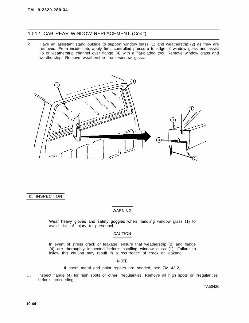
TM 9-2320-289-34
10-12. CAB REAR WINDOW REPLACEMENT (Con’t).
2 . Have an assistant stand outside to support window glass (1) and weatherstrip (2) as they areremoved. From inside cab, apply firm, controlled pressure to edge of window glass and assistlip of weatherstrip channel over flange (4) with a flat-bladed tool. Remove window glass andweatherstrip. Remove weatherstrip from window glass.
b. INSPECTION
WARNING
Wear heavy gloves and safety goggles when handling window glass (1) toavoid risk of injury to personnel.
CAUTION
In event of stress crack or leakage, ensure that weatherstrip (2) and flange(4) are thoroughly inspected before installing window glass (1). Failure tofollow this caution may result in a recurrence of crack or leakage.
NOTE
If sheet metal and paint repairs are needed, see FM 43-2,
1 . Inspect flange (4) for high spots or other irregularities. Remove all high spots or irregularitiesbefore proceeding,
TA50420
10-44

TM 9-2320-289-34
10-12. CAB REAR WINDOW REPLACEMENT (Con’t).
2 . Inspect weatherstrip (2) for damage. Replace weatherstrip if damaged.
3 . Inspect replacement window glass (1) to ensure that there are no chipped edges or otherirregularities. Obtain another window glass if repairs cannot be made.
c . INSTALLATION
WARNING
Wear heavy gloves and safety goggles when handling window glass (1) toavoid risk of injury to personnel.
1. Install weatherstrip (2) to window glass (1).
2 . Position window glass (1) and weatherstrip (2), and install weatherstrip to flange (4) alongbottom edge of window opening. Work remaining sides of weatherstrip and window glass intoflange.
3 . Once installed, inspect to ensure that weatherstrip (2) is completely seated around flange (4)and cab rear panel (3).
10-45

TM 9-2320-289-34
10-13. CARGO BENCH SEAT REPAIR (ALL EXCEPT M1009 AND M1010).
This task covers: a. Disassembly b. Assembly
INITIAL SETUP:
Equipment Condition MaterialslParts
l Bench seat removed. l Hog rings (as required)(See TM 9-2320-289-20)
Too/s/Test Equipment
l Screwdriver bit set, J-29843l Hog ring pliers
a . DISASSEMBLY
1 . Remove 10 screws (6) and 2 trim covers (7) from bench seat assembly (11).
2 . Remove 2 striker bolts (5), frame catches (4), and flat washers (8) from seatback assembly(1).
3 . Remove 2 bushings (2) and grommet (3) from each frame catch (4) if worn or damaged.
4 . Remove 2 seatback frame bolts (9) and washers (10) from seatback assembly (1).
5 . Lift off seatback assembly (1) from bench seat assembly (11).
TA60421
10-46

TM 9-2320-289-34
10-13. CARGO BENCH SEAT REPAIR (ALL EXCEPT M1009 AND M1010) (Con’t).
NOTE
On seatback assembly (1) and bench seat assembly (11) there are 51 hogrings (12) distributed between two assemblies. Quantity per assembly mayvary for different trucks. Quantity of hog rings installed for both seatbackand bench seat assemblies must be the same as number of hog rings that
6. Remove hog rings (12) seatback fram assembly (15). and remove trim (14) and pad(13) from seatback frame assembly. Discard hog rings.
7. Remove hog rings (12) from bench seat frame assembly (1 6), and remove trim (18) and pad(17) from bench seat frame assembly. Discard hog rings.
10-47

TM 9-2320-289-34
10-13. CARGO BENCH SEAT REPAIR (ALL EXCEPT M1009 AND M1010) (Con’t).
b . ASSEMBLY
NOTE
When Installing corner hog rings (12) on bench seat frame assembly (16),take extra care to prevent bench seat assembly from becoming wrinkled.
1 . Install pad (17) and trim (18) to bench seat frame assembly (16), and carefully secure withnew hog rings (12).
NOTE
When assembling seatback assembly (1) install hogdepressions on pad (13) and seatback frame assemblyhog rings first.
rings (12) over(15), and install
2 . Install pad (13) and trim (14) to seatback frame assembly (1 5), and carefully secure with newhog rings (12).
3 . Place seatback assembly (1) on bench seat assembly (11).
4 . If removed, install 2 bushings (2) and grommet (3) to frame catch (4).
5 . Install 2 frame catches (4) with striker bolts (5) and flat washers (8) to seatback assembly (1).
6 . Install 2 seatback frame bolts (9) and washers (10) to seatback assembly (1).
7 . Install 2 trim covers (7) with 10 screws (6) to bench seat assembly (11).
TA50423
10-48

TM 9-2320-289-34
10-13. CARGO BENCH SEAT REPAIR (ALL EXCEPT M1009 AND M1010) (Con’t).
FOLLOW-ON TASKS:
● Install bench seat. (See TM 9-2320-289-20)
TA50424
10-49/ (10-50 blank)

TM 9-2320-289-34
Section IV. UTILITY TRUCK BODY MAINTENANCE
10-14. UTILITY TRUCK BODY MAINTENANCE INDEX.
ParagraphNumber
10-15.10-16.10-17.
Procedures
Utility Truck Top Assembly Replacement (Ml 009) . . . . . . . . . . . . .Driver’s and Passenger’s Seat Repair (M1009 and M1010) . . . . . . . . Rear Bench Seat Repair (Ml 009) . . . . . . . . . . . . . ... . .
PageNumber
10-5210-5710-61
10-51

TM 9-2320-289-34
10-15. UTILITY TRUCK TOP ASSEMBLY REPLACEMENT (M1009).
This task covers: a. Removal b. Installation
INITIAL SETUP:
Equipment Condition
● Endgate open.
a . REMOVAL
1 . Remove 4 bolts (1 O) and 2 bolts (9)from top assembly (14).
2 . Remove 7 bolts (13), 2 front bolts(12), and bolt (3) from top assembly(14).
3. On right side, remove 3 bolts (4),washers (6), and radio mountingbracket assembly (5).
4. Loosen bolt (1) and move spare tirebrace (2) out of way.
5. Remove 2 bolts (20) from topassembly (14).
CAUTION
T o p a s s e m b l y ( 1 4 ) m u s t b ecarefully removed to prevent sidesfrom flexing. Failure to follow thiscaution may result in damage totop assembly.
6. Have assistant on opposite side of topassembly (14) and together, lift topassembly from truck.
TA50425
10-52

TM 9-2320-289-34
10-15. UTILITY TRUCK TOP ASSEMBLY REPLACEMENT (M1009) (Con’t).
7 . If 2 guide pins (17) are damaged, remove 2 nuts (19), Iockwashers (18), and guide pins.Discard Iockwashers and guide pins.
TA50426
10-53

TM 0-2320-289-34
10-15. UTILITY TRUCK TOP ASSEMBLY REPLACEMENT (M1009) (Con’t).
8 . If damaged, or if replacing top assembly (14), remove radio antenna grommet (1 6).
9 . Inspect 2 side weatherstrips (7),damage. Replace any damaged
b . INSTALLATION
front weatherstrips (8 and 11), and rear weatherstrip (15) forweatherstrips.
1.
2 .
3 .
4 .
5 .
6.
7 .
8 .
If removed, install radio antenna grommet (16) to top assembly (14),
Install 2 new guide pins (17) with new Iockwashers (18) and nuts (19) if removed.
CAUTION
Top assembly (14) must be carefully installed to prevent sides fromflexing. Failure to follow this caution may result in damage to topassembly.
Have assistant on opposite side of top assembly (14) and together, lift top assembly onto truckusing 2 guide pins (17) as locators.
Install 2 bolts (9) to top assembly(14) and cab,
On right side, position radio mountingbracket assembly (5), and install 3bolts (4) and washers (6).
NOTE
When installing 7 bolts (13), startwith bolts nearest endgate andwork towards cab.
Install 7 bolts (13) to sides of topassembly (14).
Loosen 2 bolts (9) and install 2 frontbolts (12) to top assembly (14).
Install 4 bolts (1 O) and tighten 2 bolts(9). Install 2 bolts (20).
T A 6 0 4 2 7
10-54

TM 9-2320-289-34
10-15. UTILITY TRUCK TOP ASSEMBLY REPLACEMENT (M1009) (Con’t).
10-55

TM 9-2320-289-34
10-15. UTILITY TRUCK TOP ASSEMBLY REPLACEMENT (M1009) (Con’t).
9. Install spare tire brace (2) with bolt(3). Tighten bolt (1).
FOLLOW-ON TASKS:
• Close endgate.• Check operation of endgate window.
TA50429
10-56

TM 9-2320-289-34
10-16. DRIVER’S AND PASSENGER’S SEAT REPAIR (M1009 AND M1010).
This task covers: a. Disassembly b . Assembly
INITIAL SETUP:
Equipment Condition Materials/Parts
● Driver’s or passenger’s seat removed, ● Hog rings (as required)(See TM 9-2320-289-20)
• Seat adjuster assembly removed.(See TM 9-2320-289-20)
Too/s/Test Equipment
● Screwdriver bit set, J-29843● Hog ring pliers● Torque wrench
a . DISASSEMBLY
●
●
NOTE
M1010 seat assembly does not have a specified number of hog rings.Ensure that location of all M1010 hog rings is noted for installation.
Driver’s and passenger’s seats are disassembled the same way.Driver’s seat disassembly is given.
10-57

TM 9-2320-289-34
10-16. DRIVER’S AND PASSENGER’S SEAT REPAIR (M1009 AND M1010) (Con’t).
1 .
2 .
3 .
4 .
5.
6.
7.
8 .
9 .
NOTE
● If disassembling M1009 seatback assembly (2), perform Steps 1-5,and 7.
● If disassembling M1009 seat cushion assembly (18), perform steps1-3, 8, and 9.
● If disassembling M1010 seat assembly, perform steps 6-9.
Remove 4 screws (7) and upper and lower seatback lock covers (9 and 10).
NOTE
If disassembling passenger’s seat, seat adjuster cable is disconnectedwhen seatback lock assembly (11) is removed.
Remove 4 bolts (8) and seatback lock assembly (11).
Remove pivot bolt (17), washer (1 6), and bushing (12). Lift off seatback assembly (2) fromseat cushion assembly (18).
Unzip seatback trim (6) zipper. Remove any hog rings (5) found securing seatback trim toseatback frame (4). Discard hog rings.
Remove 2 hog rings (5) securing looped ends of 2 lasting wires (1) to seatback frame (4).Remove 2 lasting wires. Remove M1009 seatback trim (6). Discard hog rings.
Remove any hog rings (5) found securing seatback trim (6) to seat frame (13). RemoveMl 010 seatback trim. Discard hog rings.
Inspect seatback frame (4), pad (3), and seatback trim (6) for damage. Replace if damaged.
Remove 17 hog rings (5) securing seat cushion trim (15) to seat frame (13) and springs.Remove seat cushion trim. Discard hog rings.
Inspect seat frame (13), cushion (14), and seat cushion trim (15) for damage. Replace ifdamaged.
b. ASSEMBLY
NOTE
● Driver’s and passenger’s seats are assembled the same way. Driver’sseat assembly is given.
● If assembling M1009 seat cushion assembly (18), perform steps 1, 2,and 6 through 8.
● If assembling M1009 seatback assembly (2), perform steps 4-8.
● If assembling M1010 seat assembly, perform steps 1 and 3.
1 . Install seat cushion trim (15) to seat frame (13) and cushion (14) with 15 new hog rings (5) atfront and sides. Secure seat cushion trim at rear to springs with 2 new hog rings.
10-58

TM 9-2320-289-34
10-16. DRIVER’S AND PASSENGER’S SEAT REPAIR (M1009 AND M1010) (Con’t).
2 . Make 2 holes in seat cushion trim (15) where seatback lock assembly (11) bolts (8) will beinstaIled.
3 . Install M1010 seatback trim (6) to seatback frame (4) and pad (3). Secure seatback trim toseat frame (13) with new hog rings (5).
4 . Install seatback trim (6) to seatback frame (4) and pad (3). Slide in 2 lasting wires (1) throughhemmed channels in seatback trim, engaging straight ends of wires under seatback frame.Secure looped ends of wires to seatback frame with 2 new hog rings (5),
5. Use new hog rings (5) as required to secure loose ends of M1009 seatback trim (6) toseatback frame (4), Close zipper and tuck under zipper ends. Make 2 holes in trim whereseatback lock assembly (11) bolts (8) will be installed.
6 . Place seatback assembly (2) on seat cushion assembly (18). Install pivot bolt (17), washer(16), and bushing (12).
TA50430
10-59

TM 9-2320-289-34
10-16. DRIVER’S AND PASSENGER’S SEAT REPAIR (M1009 AND M1010) (Con’t).
NOTE
If assembling passenger’s seat, ensure that seat adjuster cable isassembled with seatback lock assembly (11).
7 . Install seatback lock assembly (11) with 4 bolts (8). Tighten bolts to 20 Ib.-ft. (27 N.m).
8 . Install upper and lower seatback lock covers (9 and 10) with 4 screws (7).
FOLLOW-ON TASKS:
● Install seat adjuster assembly. (See TM 9-2320-289-20)● Install driver’s or passenger’s seat, (See TM 9-2320-289-20)
TA50431
10-60

TM 9-2320-289-34
10-17. REAR BENCH SEAT REPAIR (M1009).
This task covers: a. Disassembly b. Assembly
INITIAL SETUP
Equipment Condition Materials/Parts
● Rear bench seat removed. ● Hog rings (as required)(See TM 9-2320-289-20)
Tools/Test Equipment
● Screwdriver bit set, J-29843● Hog ring pliers
a . DISASSEMBLY
NOTE
● if disassembling seatback assembly (3), perform steps 1-4.
● If disassembling bench seat assembly (2), perform steps 1, 2, and5 through 11.
1 . Remove 2 bolts (8) from seatback assembly (3), 2 torx head bolts (9)assembly (2), and remove seatback hinge (10). Remove knob (7) fromdamaged. Repeat this step for hinge on other side.
from bench seatseatback hinge if
TA50432
10-61

TM 9-2320-289-34
10-17. REAR BENCH SEAT REPAIR (M1009) (Con’t).
2 . Separate seatback assembly (3) from bench seat assembly (2).
3 . Unzip zipper and remove trim (4) from seatback assembly (3), and remove pad (5) fromseatback frame assembly (6).
4 . Inspect trim (4), seatback frame assembly (6), and pad (5) for damage. Replace if damaged.
5 . Remove 16 screws (17) and remove bench seat trim panel (16).
6 . Mark one end of front hinge torque rod (14) to ensure proper assembly, and remove bolt (15)and front hinge torque rod.
TA50433
10-62

TM 9-2320-289-34
10-17. REAR BENCH SEAT REPAIR (M1009) (Con’t).
7. Mark one end of actuating rod (21) toensure proper assembly and remove2 ring clips (20) and actuating rod.
1 0 .
11.
8. Remove 4 bolts (26), 2 seatbelt mounting bolts (24), latch and guide assembly (25), and latchcover (23). Note location of 2 seatbelt assemblies to ensure proper assembly and removefrom bench seat assembly (2).
9. Remove 2 hinge pins (13), 4 bushings(11), and 2 hingesseat assembly (2).
NOTE
Quantity of hog ringssecure trim (18) toframe assembly (19)different trucks.
(12)’ from bench
(22) used tobench seatwill vary for
Remove hog rings (22) securing trim(18) to bench seat frame assembly(19), and remove trim and pad (1)from bench seat frame assembly.Discard hog rings.
Inspect trim (18), bench seat frameassembly (19) and pad (1) fordamage. Replace if damaged.
TA50434
10-63

TM 9-2320-289-34
10-17. REAR BENCH SEAT REPAIR (M1009) (Con’t).
b . ASSEMBLY
NOTE
● If assembling bench seat assembly (2), perform steps 1-6, and 8.
• If assembling seatback assembly (3), perform steps 7 and 8.
● When installing corner hog rings (22) on bench seat frame assembly(19) take extra care to prevent trim (18) from becoming wrinkled. Usehog rings (22) as required to ensure a tight, wrinkle free fit.
1. Install pad (1) to bench seat frame assembly (19). Using new hog rings (22), install trim (18)and secure to bench seat frame assembly. Make holes in trim around bench seat frameassembly for bolt and screws to be installed.
TA50435
10-64

TM 9-2320-289-34
10-17. REAR BENCH SEAT REPAIR (M1009) (Con’t).
NOTE
Ensure that square corners ofseatback frame assembly (6) arepointed to bottom of seat.
2 . Install 2 hinges (12) to bench seatassembly (2) with 4 bushings (11)and 2 hinge pins (13).
3 . Install latch cover (23) and latch andguide assembly (25) with 4 bolts(26), and install 2 seatbeltassemblies in their original positionwith 2 bolts (24). Tighten 2 bolts (24)to 40 Ib.-ft. (54 N.m).
4 . Install actuating rod (21 ), as marked,with 2 ring clips (20).
5 . Install front hinge torque rod (14), asmarked, with bolt (1 5).
6 . Install 16 screws (17) and bench seattrim panel (16) to bench seatassembly (2).
7 . Install pad (5) to seatback frameassembly (6). Install trim (4) andclose zipper. Tuck under zipper ends.
8 . Position seatback assembly (3) onbench seat assembly (2) and installhinge (1 O) with 2 bolts (8) and torxhead bolts (9). Install knob (7) onhinge if removed.
FOLLOW-ON TASKS:
● Install rear bench seat. (See TM 9-2320-289-20)
TA50436
10-65/(10-66 blank)

TM 9-2320-289-34
Sect ion V. AMBULANCE BODY MAINTENANCE
10-18. AMBULANCE BODY MAINTENANCE INDEX.
ParagraphNumber
10-19.10-20,10-21.10-22.10-23.10-24.10-25.10-26.10-27.
Procedures
Personnel Heater Control Box Repair (M1010) . . . . . . . . . . . . . . . .Air Conditioning System Testing (M1010) . . . . . . . . . . . . . . . . . . . .Air Conditioning System Servicing (M1010) . . . . . . . . . . . . . . . . . . .Air Conditioner Control Panel and Louver Repair (M1010) . . . . . . .Air Conditioner Assembly Replacement (M1010) . . . . . . . . . . . . . .Air Conditioner Compressor Maintenance (M1010) . . . . . . . . . . . .Air Conditioner Lines Replacement (M1010) . . . . . . . . . . . . . . . . . .Air Conditioner Condenser Replacement (M1010) . . . . . . . . . . . . .Air Conditioner Expansion Valve, Evaporator, andReceiver-Dehydrator Replacement (M1010) . . . . . . . . . . . . . . . . . .
PageNumber
10-6810-7410-7910-8410-8810-90
10-10010-105
10-108
10-67

TM 9-2320-289-34
10-19. PERSONNEL HEATER CONTROL BOX REPAIR (M1010).
This task covers: a. Disassembly b . Assembly
INITIAL SETUP:
Equipment Condition MaterialslParts
● Personnel heater control box removed. ● TWO sheet spring nuts(See TM 9-2320-289-20)
a . DISASSEMBLY
NOTE
Ensure that all leads are tagged for assembly.
1 . Remove 8 screws (1) and separate cover (2) from control wrap (10).
2 . Remove 5 screws and disconnectharness (12) leads from “RUN-START” switch (4), “ HI-LO” switch(6), c i r cu i t b reaker (20 ) , andsensitive switches (15), Remove 4screws (9) and harness if damaged.
3 . Remove blend air door grommet (8)and fresh air door grommet (7) ifdamaged.
4 . Remove screw and lead (19) fromcircuit breaker (20). Disconnect lead(22) and socket (17) lead from circuitbreaker. Remove 2 nuts (18), screws(21), and circuit breaker from cover(2) .
5 . Remove screw and disconnect lead(11) from “HI-LO” switch (6).Remove 2 screws (23), lead (22),and lead (11) from “ RUN-START”switch (4). Disconnect 2 leads (13)and socket (17) lead from“RUN-START” switch. Remove 2screws (3) and “RUN-START” switch.
6 . Remove nut (5) and “HI-LO” switch(6) .
7 . Remove 2 leads (13) from 2 sensitive switches (15). Remove 4 nuts (16), screws (14), and 2sensitive switches from cover (2).
8 . Remove pilot cover, bulb, nut, and socket (17) from cover (2).
TA50437
10-68
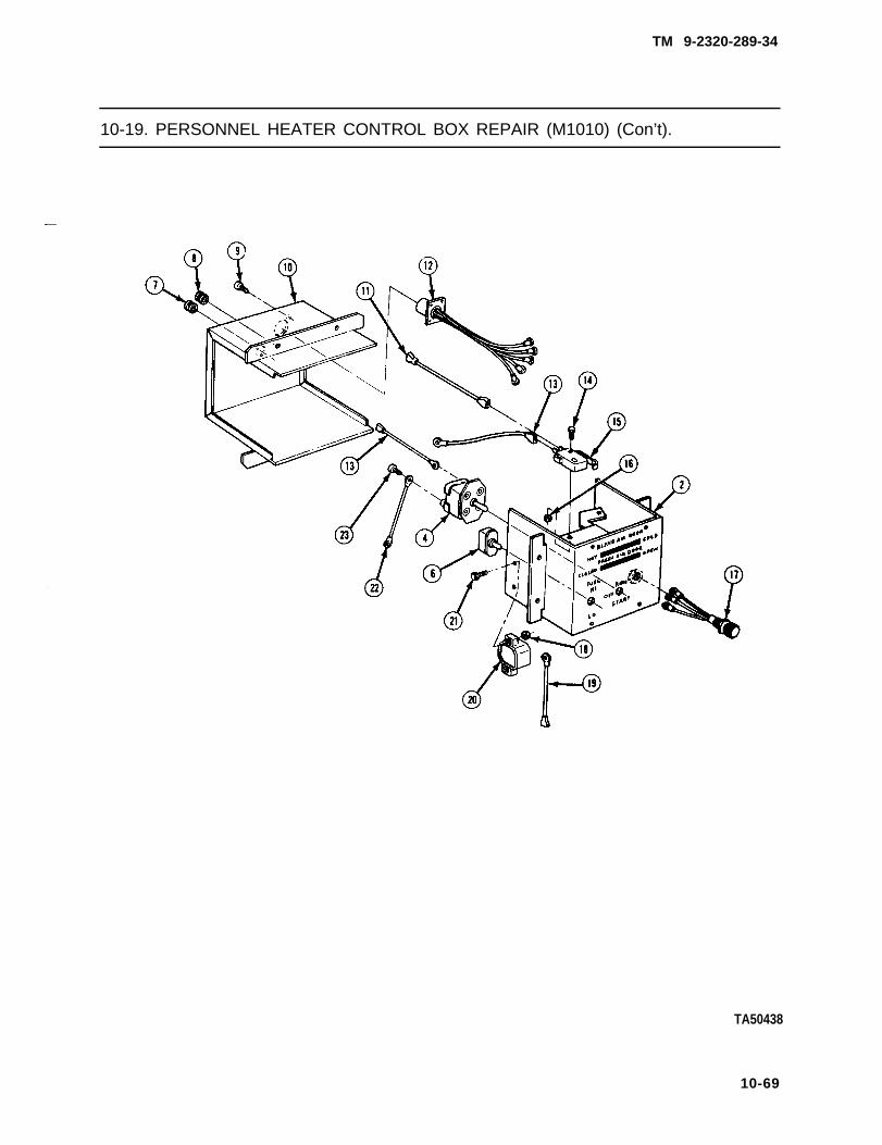
TM 9-2320-289-34
10-19. PERSONNEL HEATER CONTROL BOX REPAIR (M1010) (Con’t).
TA50438
10-69

TM 9-2320-289-34
10-19. PERSONNEL HEATER CONTROL BOX REPAIR (M1010) (Con’t).
9 .
1 0 .
1 1 .
1 2 .
1 3 .
Mark relationship of cables (24) toclamps (32). Remove 2 screws (31)and clamps from cover (2).
Remove 2 sheet spring nuts (27) andcables (24) from blend air door lever(28) and fresh air door lever (34).Discard sheet spring nuts.
Remove 2 screws (29) and knobs(30) from blend air door lever (28)and fresh air door lever (34) ifdamaged.
Remove nut (33), 2 washers (25),screw (26), and blend air door lever(28) .
Remove fastener (35) and fresh airdoor lever (34).
b . ASSEMBLY
1 . Install fresh air door lever (34) withfastener (35).
2. Install blend air door lever (28) withscrew (26), 2 washers (25), and nut(33) .
3 . Install 2 knobs (30) on blend air doorlever (28) and fresh air door lever(34) with 2 screws (29) if removed.
4. Install 2 cables (24) on blend air doorlever (28) and fresh air door lever(34) with 2 new sheet spring nuts(27) .
5 . Install 2 clamps (32) on cover (2) with2 screws (31),
6 . Install socket (17), nut, bulb, and pilot cover on cover (2).
7 . Install 2 sensitive switches (15) on cover (2) with 4 screws (14) and nuts (16). Install 2 leads(13) on sensitive switches.
TA50439
10-70

TM 9-2320-289-34
10-19. PERSONNEL HEATER CONTROL BOX REPAIR (M1010) (Con’t).
8 . Install “HI-LO” switch (6) on cover (2)with nut (5).
9 . Install “RUN-START” switch (4) oncover (2) with 2 screws (3). Connect2 leads (13) and socket (17) lead to“RUN-START” switch. Connect lead(11) and lead (22) to “RUN-START”switch with 2 screws (23). Connectlead (11) to “HI-LO” switch (6) withscrew.
10. Install circuit breaker (20) on cover(2) with 2 screws (21) and nuts (18).Connect socket (17) lead and lead(22) to circuit breaker. Install lead(19) on circuit breaker with screw.
TA50440
10-71

TM 9-2320-289-34
10-19. PERSONNEL HEATER CONTROL BOX REPAIR (M1010) (Con’t).
11. Install blend air door grommet (8) and fresh air door grommet (7) if removed.
12. Install harness (12) on control wrap (10) with 4 screws (9) if removed. Connect harness leadsto “RUN-START” switch (4), “HI-LO” switch (6), circuit breaker (20), and sensitive switches(15) with 5 screws.
TA50441
10-72

TM 9-2320-289-34
10-19. PERSONNEL HEATER CONTROL BOX REPAIR (M1010) (Con’t).
NOTE
Ensure that cables and circuit breaker lead (19) are placed through theirappropriate holes as cover (2) and control wrap (10) are assembled.
13. Assemble cover (2) and control wrap(10) and install 8 screws (1).
FOLLOW-ON TASKS:
● Install personnel heater control box. (See TM 9-2320-289-20)
TA50442
10-73

TM 9-2320-289-34
10-20. AIR CONDITIONING SYSTEM TESTING (M1010).
This task covers: a. Testing
INITIAL SETUP:
Materials/Parts Tools/Test Equipment● Refrigerant (Item 54, Appendix B) • Charging station
● STE/lCE
Manual References● TM 9-4910 -571-12&P
General Safety Instructions● Always wear goggles when testing or servicing air conditioning system. DO NOT allow refrigerant
to contact your skin.● DO NOT test or service air conditioning system while smoking or near open flame. Refrigerant will
become a poisonous gas when burned.● DO NOT allow direct flame or electric heaters to contact refrigerant container.● Never open high side valve on air conditioner manifold gage set while air conditioning system is
operating.● Never attempt to connect servicing equipment while air conditioning system is running.
a. TESTING
WARNING
● Always wear goggles when testing or servicing air conditioning system.DO NOT allow refrigerant to contact your skin. Failure to follow thiswarning may result in injury to personnel.
● DO NOT test or service air conditioning system while smoking or nearopen flame. Refrigerant will become a poisonous gas when burned.Failure to follow this warning may result in serious illness or death topersonnel.
● DO NOT allow direct flame or electric heaters to contact refrigerantcontainer (1). Localized heat can raise pressure to a dangerous level andcause refrigerant container to explode, resulting in serious injury ordeath to personnel.
● Never attempt to connect servicing equipment while air conditioningsystem is running. Failure to follow this warning may result in injury topersonnel.
1 . Completely close low side valve (3) and high side valve (6) on manifold gage set.
2 . Remove protective caps from low pressure line (9) valve and high pressure line (10) valve.Loosely connect low pressure hose (8) to low pressure line valve and high pressure hose (7) tohigh pressure line valve, Connect center hose (2) to valve on refrigerant container (1).
10-74 change 2

TM 9-2320-289-34
10-20. AIR CONDITIONING SYSTEM TESTING (M1010) (Con’t).
NOTE
Purging of air will take place as refrigerant in refrigerant container (1)forces air out of system at loose hose connections.
3 . Slowly open refrigerant container (1) valve and high side valve (6). After 4 seconds, closerefrigerant container valve and high side valve. Tighten high pressure hose (7) at high pressureline (10) valve.
4 . Repeat step 3 for low side valve (3) and low pressure hose (8).
CAUTION
All testing equipment should be kept clear of moving parts while engine isrunning. Failure to follow this caution may result in damage to enginecomponents and testing equipment.
5 . Connect STE/lCE tester to STE/lCE DCA connector under dash. (See TM 9-4910-571-12&P)Start engine and operate at approximately 1500 rpm.
TA50443
10-75

TM 9-2320-289-34
10-20. AIR CONDITIONING SYSTEM TESTING (M1010) (Con’t).
6 . on air conditioner control panel, turn “VENT-A/C” toggle switch to “ VENT, ” air selection leverto “ OUTSIDE, “ “ A/C COLD” knob to coldest setting, and fan switch to “H1.” Open ambulancerear doors briefly to exhaust any built up heat. Operate for a minimum of 5 minutes.
7 . Close ambulance rear doors tightly. Place thermometer at air conditioner center vent for 5minutes, then check temperature.
8 . Check low side gage (4) and high side gage (5) and determine performance of air conditioningsystem using Table 10-1. High outlet temperature or low pressure at either gage indicate thatsystem is low on refrigerant.
Table 10-1. Air Conditioning System Performance
Air Inlet (Outside)Temperature
70°F (21°C)
80°F (26°C)
90°F (32°C)
100°F (37°C)
Low Side Pressure
8-13 psi(55-89 kPa)
13-18 psi(89-1 24 kPa)
17–22 psi(1 18-151 kPa)
23–28 psi(1 58-193 kPa)
It may be necessary
9 . Remove p lug (12) f rom top o fcondenser cover (11) and check forbubbles in sight glass. Bubblesindicate that system is low onrefrigerant,
High Side Pressure
1 30–150 psi(890-1 034 kPa)
165-185 psi(1 137-1276 kPa)
190-210 psi(1310-1447 kPa)
225-245 psi(1551-1749 kPa)
NOTE
Air Outlet (Inside)Temperature
33-35°F (1-2°C)
38-42°F (3-5°C)
45-49°F (7-9°C)
52-56°F (11-13°C)
to scrape paint off sight glass.
TA50444
10-76

TM 9-2320-289-34
10-20. AIR CONDITIONING SYSTEM TESTING (M1010) (Con’t).
WARNING
Never open high side valve (6) on air conditioner manifold gage set whileair conditioning system is operating, Refrigerant may be pumped backinto refrigerant container (1) and cause refrigerant container to explode,resulting In serious lnjury or death to personnel.
NOTE
● Perform step 10 if air conditioning system was determined to be low onrefrigerant.
• Ensure that engine is still running at 1500 rpm before performingstep 10.
● Ensure that refrigerant container (1) remains upright when addingrefrigerant through low side valve (3),
10. Slowly open refrigerant container (1) valve and low side valve (3). Add refrigerant until gagereadings return to normal range and bubbles clear up in sight glass. Close low side valve andrefrigerant container valve.
TA50445
10-77

TM 9-2320-289-34
10-20. AIR CONDITIONING SYSTEM TESTING (M1010) (Con’t).
11.
12.
13.
14.
15.
Service air conditioning system if stillnot operating properly. (Seeparagraph 10-21 )
Install plug (12) on top of condensercover (11).
Turn off engine. Disconnect STE/lCEtester from STE/lCE DCA connectorunder dash. (See TM 9-4910-571-12&P)
Disconnect center hose (2) fromrefrigerant container (1) valve.Disconnect low pressure hose (8)from low pressure line (9) valve andhigh pressure hose (7) from highpressure line (10) valve.
Ins ta l l p ro tec t i ve caps on lowpressure line (9) valve and highpressure line (10) valve.
TA50446
10-78

TM 9-2320-289-34
10-21. AIR CONDITIONING SYSTEM SERVICING (M1010).
This task covers: a . Discharging System c. Charging Systemb. Evacuating System
INITIAL SETUP:
Materials/Parts Tools/Test Equipment● Refrigerant (Item 54, Appendix B) • Charging station
• Refrigerant gas leak detector● STE/lCE● Vacuum pump
Manual References
● TM 9-4910 -571-12&P
General Safety Instructions●
●
●
●
●
Always wear goggles when testing or servicing air conditioner system. DO NOT allow refrigerantto contact your skin.DO NOT test or service air conditioner system while smoking or near open flame. Refrigerant willbecome a poisonous gas when burned.DO NOT allow direct flame or electric heaters to contact refrigerant container.Never open high side valve on air conditioner manifold gage set while air conditioning system isoperating,Never attempt to connect servicing equipment, discharge system, or charge system while airconditioning system is running.
a. DISCHARGING SYSTEM
WARNING
Always wear goggles when testing or servicing air conditioner system.DO NOT allow refrigerant to contact your skin. Failure to follow thiswarning may result in injury to personnel.
DO NOT test or service air conditioner system while smoking or nearopen flame. Refrigerant will become a poisonous gas when burned.Failure to follow this warning may result in serious illness or death topersonnel.
DO NOT allow direct flame or electric heaters to contact refrigerantcontainer. Localized heat can raise pressure to a dangerous level andcause refrigerant container to explode, resulting in serious injury ordeath to personnel.
Never open high side valve on air conditioner manifold gage set while airconditioning system is operating. Refrigerant may be pumped back intorefrigerant container and cause refrigerant container to explode,resulting in serious injury or death to personnel.
Never attempt to connect servicing equipment or discharge systemwhile air conditioning system is running, Failure to follow this warningmay result in injury to personnel.
Change 2 10-79

TM 9-2320-289-34
10-21. AIR CONDITIONING SYSTEM SERVICING (M1010) (Con’t).
1 .
2 .
3 .
4 .
5 .
NOTE
Ensure that DISCHARGING SYSTEM is performed to remove al lcontamination and refrigerant from air conditioning system beforeperforming EVACUATING SYSTEM.
Completely close low side valve (1) and high side valve (4) on manifold gage set.
Remove protective caps from low pressure line (8) valve and high pressure line (9) valve.Connect low pressure hose (7) to low pressure line valve and high pressure hose (5) to highpressure line valve.
Wrap end of center hose (6) with a clean rag. Slowly open high side valve (4). Observe centerhose (6) for evidence of refrigerant oil in rag. Adjust high side valve toward closed position toprevent refrigerant oil from escaping while discharging system.
When high side gage (3) reads 50 psi (345 kPa), slowly open low side valve (1). Refrigerantshould flow at an even rate from both sides of system.
When both gages reach “O, ” completely close low side valve (1) and high side valve (4) onmanifold gage set.
TA50447
1 0 - 8 0

TM 9-2320-289-34
10-21. AIR CONDITIONING SYSTEM SERVICING (M1010) (Con’t).
b. EVACUATING SYSTEM
CAUTION
Compressor (10) should not be used as a vacuum pump. Failure to followthis caution may result in damage to compressor.
NOTE
If air conditioning system is determined to be leaking at any time whileperforming EVACUATING SYSTEM, air conditioning system will have to becharged and checked for leaks.
1 . Connect center hose (6) to vacuum pump (11), Completely open low side valve (1) and highside valve (4), Open discharge valve on vacuum pump.
2 . Start vacuum pump (11), Low side gage (2) should go down to 29 in. Hg. If 29 in. Hg is notobtained, there is a leak in air conditioning system. Locate leak, if present, using refrigerantgas leak detector. Repair leak in system, if present, before performing step 3.
TA50448
10-81

TM 9-2320-289-34
10-21. AIR CONDITIONING SYSTEM SERVICING (M1010) (Con’t).
3 . When low side gage (2) needle stabilizes at 29 in. Hg, operate vacuum pump (11) for anadditional 30 minutes. Completely close low side valve (1) and high side valve (4) on manifoldgage set. Close discharge valve on vacuum pump, Wait 5 minutes, and check to see if lowside gage needle moves. If low side gage needle moves, there is a leak in air conditioningsystem. Locate leak, if present, using refrigerant gas leak detector. Repair leak in system ifpresent, and repeat this step before performing step 4.
4 . If low side gage (2) needle position remains constant, disconnect center hose (6).
c. CHARGING SYSTEM
WARNING
● Never Open high side valve (4) on air conditioner manifold gage setwhile air conditioning system is operating. Refrigerant may be pumpedback into refrigerant container (12) and cause refrigerant container toexplode, resulting in serious Injury or death to Personnel.
● Never attempt to charge system on the high side while air conditioningsystem is running. Failure to follow this warning may result in injury topersonnel.
TA50449
10-82

TM 9-2320-289-34
10-21. AIR CONDITIONING SYSTEM SERVICING (M1010) (Con’t).
5.
8.
12.
NOTE
Ensure that refrigerant container (12) is upright when performing step 1.
1. Connect center hose (6) to valve on refrigerant container (12). With refrigerant containerupright, loosen center hose at manifold gage set and slowly open refrigerant container valve.After 2 seconds, close refrigerant container valve and tighten center hose.
2. Invert refrigerant container (12) and place on a scale.
3. Open refrigerant container (12) valve and high side valve (4). Continue charging until scaleindicates that refrigerant container has decreased in weight by 70 oz. (1.97 kg). If refrigerantcontainer has decreased in weight by 70 oz. (1.97 kg), close refrigerant container valve andhigh side valve and perform step 9.
4. f refrigerant container (12) has not decreased in weight by 70 oz. (1.97 kg), record weightused in step 3. Close high side valve (4) and refrigerant container valve. Turn refrigerantcontainer upright and place on a scale,
Connect STE/lCE tester to STE/lCE DCA connector under dash. (See TM 9-4910 -571-12&P)Start engine and operate at approximately 1500 rpm.
6. On air conditioner control panel, turn air selection lever to “OUTSIDE. ”
7. Slowly open refrigerant container (12) valve and low side valve (1). Adjust low side valve asneeded to prevent pressure on low side gage (2) from exceeding 50 psi (345 kPa) andpressure on high side gage (3) from exceeding 240 psi (1 655 kPa).
When refrigerant container (12) has decreased in weight by a total of 70 oz. (1 .97 kg),including charging done in step 3, close refrigerant container valve and low side valve (1).
9. Determine performance of air conditioning system by performing steps 7 and 8 inparagraph 10-20.
10. Turn off engine, Disconnect STE/lCE tester from STE/lCE DCA connector under dash. (SeeTM 9-4910-571-12&P)
11. Disconnect center hose (6) from refrigerant container (12) valve. Disconnect low pressurehose (7) from low pressure line (8) valve and high pressure hose (5) from high pressure line(9) valve.
Install protective caps on low pressure line (8) valve and high pressure line (9) valve.
10-83

TM 9-2320-289-34
10-22. AIR CONDITIONER CONTROL PANEL AND LOUVER REPAIR (M1010).
This task covers: a. Disassembly b. Assembly
INITIAL SETUP:
Equipment Condition Materials/Parts
● Both battery negative cables disconnected. ● Eight Iockwashers(See TM 9-2320-289-20)
• Evaporator removed (if removing louvers).(See paragraph 10-27)
a. DISASSEMBLY
1.
2.
3 .
4 .
5 .
6 .
7 .
NOTE
• If removing louver (8), perform step 1.
● If disassembling control panel (18) assembly, perform steps 2-7.
From rear of air outlet box (1), remove 4 sheet spring nuts (7) and louver (8). Repeat asneeded for other 5 louvers,
Remove screw (14) and knob (1 3).
Remove 8 screws (11), Iockwashers (10), and control panel (18) from air outlet box (1).Discard Iockwashers.
NOTE
Ensure that leads are tagged for installation.
Disconnect switch wiring harness (22) and leads from switches.
Disconnect lead from “VENT-A/C” switch (21). Remove nut (12) and “VENT-A/C” switch.Remove knob (15), nut (16), and “A/C COLD’; switch (20), Remove nut (17) and fan switch(19).
NOTE
On early 1984 model M1010 trucks, air selection lever (2) is mounted onright side of air outlet box (1) support,
Remove nut (25), air selection lever (2), and spring washer (3) from lever bracket (4).Remove sheet spring nut and 2 washers, and disconnect air selection lever link from airselection lever. Remove 2 nuts (6), springs (5), and lever bracket.
Remove 2 nuts (9), screws (24), and outside air door switch (23).
10-84
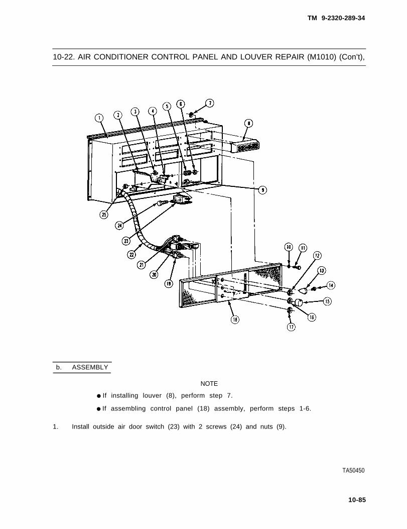
TM 9-2320-289-34
10-22. AIR CONDITIONER CONTROL PANEL AND LOUVER REPAIR (M1010) (Con’t),
b. ASSEMBLY
NOTE
● If installing louver (8), perform step 7.
● If assembling control panel (18) assembly, perform steps 1-6.
1. Install outside air door switch (23) with 2 screws (24) and nuts (9).
TA50450
10-85

TM 9-2320-289-34
10-22. AIR CONDITIONER CONTROL PANEL AND LOUVER REPAIR (M1010) (Con’t).
NOTE
On early 1984 model M1010 trucks, air selection lever (2) is mounted onright side of air outlet box (1) support. Air selection lever must contactoutside door switch (23) and go through control panel (18) opening afterinstallation,
2 . Install lever bracket (4) on air outlet box (1) with 2 springs (5) and nuts (6). Connect airselection lever link to air selection lever (2) with 2 washers and sheet spring nut. Install airselection lever on lever bracket with spring washer (3) and nut (25).
3 . Install fan switch (19) with nut (17), Install ‘“A/C COLD” switch (20) with nut (16) and knob(15). Install “VENT-A/C” switch (21) with nut (12). Connect lead to “VENT-A/C” switch.
TA50451
10-86

TM 9-2320-289-34
10-22. AIR CONDITIONER CONTROL PANEL AND LOUVER REPAIR (M1010) (Con’t).
4. Connect switch wiring harness (22) and leads to switches.
5 . Install control panel (18) on air outlet box (1) with 8 new Iockwashers (10) and screws (11).
6. Install knob (13) on air selection lever (2) with screw (14).
7 . Install louver (8) on air outlet box (1) with 4 sheet spring nuts (7). Repeat as needed for other5 louvers.
FOLLOW-ON TASKS:
• Connect both battery negative cables. (See TM 9-2320-289-20)● Install evaporator if removed. (See paragraph 10-27)• Check operation of air conditioning system.
10-87

TM 9-2320-289-34
10-23. AIR CONDITIONER ASSEMBLY REPLACEMENT (M1010).
This task covers: a . R e m o v a l b. Installation
INITIAL SETUP:
Equipment Condition Materials/Parts
● Air conditioning system discharged. ●
(See paragraph 10-21 ) ●
• Both battery negative cables disconnected. ●
(See TM 9-2320-289-20)
Personnel Required
● MOS 52C (2)
One rivetTwo preformed packing insertsTwo tie-down straps(Item 63, Appendix B)
a . REMOVAL
CAUTION
Ensure that all openings and connections are immediately plugged afterdisconnection to prevent contamination of air conditioning system.
1 . Disconnect inlet line (3) and outletline (4) from side of air conditionerassembly (1). Remove and discard 2preformed packing inserts (2) .Remove and discard 2 tie-downstraps securing drain hoses to inletline and outlet line.
2 . Inside ambulance body (5), remove 10 screws and switch panel below air conditioner controlpanel. Disconnect wiring harness connector from connector on underside of air conditionerassembly (1). Remove rivet and ground lead. Push wiring up into air conditioner assembly.Discard rivet.
TA50452
10-88

TM 9-2320-289-34
10-23. AIR CONDITIONER ASSEMBLY REPLACEMENT (M1010).
3 . Attach suitable lifting device to air conditioner assembly (1), Remove 16 screws (6) and airconditioner assembly from ambulance body (5). Remove lifting device.
b. INSTALLATION
1 . Attach suitable lifting device to air conditioner assembly (1). Install air conditioner assembly onambulance body (5) with 16 screws (6). Remove lifting device.
2 . Inside ambulance body (5), pull wiring through grommet on underside of air conditionerassembly (1). Connect wiring harness connector toassembly. Install ground lead on ambulance bodybelow air conditioner assembly with 10 screws.
NOTE
Ensure that all plugs are removed
connector on underside of air conditionerpanel with new rivet. Install switch panel
before connection.
3. Install 2 new preformed packing inserts (2) in fittings of evaporator lines (3 and 4). Connectinlet line (3) and outlet line (4) to side of air conditioner assembly (1). Secure drain hoses toinlet line and outlet line with 2 new tie-down straps,
FOLLOW-ON TASKS:
• Connect both battery negative cables, (See TM 9-2320-289-20)● Evacuate and charge air conditioning system. (See paragraph 10-21)• Check operation of air conditioning system and inspect for leakage.
TA50453
10-89

TM 9-2320-289-34
10-24. AIR CONDITIONER COMPRESSOR MAINTENANCE (M1010).
This task covers: a .Remova l d. Assemblyb. Disassembly e. Installationc. Inspection
INITIAL SETUP:
Equipment Condition Materials/ Parts
● Both battery negative cables disconnected, ●
(See TM 9-2320-289-20) ●
● Air conditioning system discharged. ●
(See paragraph 10-21 ) ●
●
●
●
●
Tools/Test Equipment
• Compressor tool kit, J-29888● Belt tensioning gage● Torque wrench
One drain screw gasketOne nut kitOne preformed packing kitOne ring kitOne seal kitOne suction screenTwo IockwashersRefrigerant oil (Item 55, Appendix B)
a . R E M O V A L
1. Loosen 3 adjusting bolts (10) and pivot nut (12), and move compressor assembly (14) toright. Remove air conditioner belt (13).
CAUTION
Ensure that all openings and connections are immediately plugged afterdisconnection to prevent contamination of air conditioning system,
2. On rear of compressor assembly (14), remove bolt and Iockwasher, and disconnectcompressor lines. Discard Iockwasher.
3. Remove bolt and Iockwasher from clip retaining electrical connector to compressor assembly(14). Disconnect electrical connector from compressor assembly. Discard Iockwasher.
4. Remove 3 adjusting bolts (10), 5 bolts (8), and pivot nut (1 2). Remove compressor assembly(14) with front adjusting bracket (11 ) and rear adjusting bracket (9).
NOTE
Perform step 5 only if brackets (4, 6, or 16) or mounting hardware aredamaged.
5. Remove 2 nuts (1), bolt (15), and lower front bracket (16) from water pump studs (2).Remove 2 nuts (3) and upper rear bracket (4) from intake manifold studs (5). Remove 2 bolts(7) and lower rear bracket (6).
10-90

TM 9-2320-289-34
10-24. AIR CONDITIONER COMPRESSOR MAINTENANCE (M1010) (Con’t),
6 . Remove drain screw and gasket from compressor assembly (14), Drain and measurerefrigerant oil in compressor assembly. Check for evidence of contamination to determine ifremainder of air conditioning system requires servicing, Discard gasket.
TA50454
10-91

TM 9-2320-289-34
10-24. AIR CONDITIONER COMPRESSOR MAINTENANCE (M1010) (Con’t).
b . DISASSEMBLY
1.
2 .
3 .
4 .
5.
6 .
7.
CAUTION
● Work area, tools, and hands must be kept clean when repairingcompressor. A parts tray should be used for all internal compressorparts and all replacement parts. Failure to follow this caution may resultin damage to compressor components.
● DC) NOT strike end of shaft (27) during disassembly of compressor.Failure to follow this caution may result in damage to compressorinternal components,
Install holding fixture (28) in vise.Install compressor assembly inholding fixture.
Hold clutch (17) in place with clutchhub holder. Remove and discardlocknut (18). Remove clutch snapring(19).
Remove clutch (17) using hub anddrive puller and installer. Remove keyfrom shaft (27) or clutch.
Remove pulley snapring (20) .Remove pul ley (23) with pul leybearing (22).
Remove pulley bearing retaining ring(21). Drive out pulley bearing (22).
Mark relationship of coil housingterminals (26) to compressor shell(29). Remove coil housing retainingring (24). Remove coil housing (25).
Remove compressor assembly fromholding f ixture (28). Remove 2preformed packing inserts (36) fromrear head (34). Remove pressurerelease valve (37) and preformedpacking insert (38) from rear head.Discard preformed packing inserts.
8 . Remove 4 nuts (35) and rear head (34) from compressor shell (29). Remove and discard “O“ring (33) and suction screen (39).
TA50455
10-92

TM 9-2320-289-34
10-24. AIR CONDITIONER COMPRESSOR MAINTENANCE (M1010) (Con’t).
CAUTION
DO NOT pry on any part of valve plate (31) or valve reed (30) except alongedge. Failure to follow this caution may result in damage to valve plate orvalve reed,
NOTE
Ensure that position of valve plate (31) and valve reed (30) is noted forassembly.
9 . Pry up on oil pump assembly (32) and remove, Gently pry along edge of valve plate (31) andremove. Gently pry along edge of valve reed (30) and remove.
10. Remove cylinder housing assembly(40) from compressor shell (29).
1 1 . Pry suction cover (41) from cylinderhousing assembly (40).
10-93

TM 9-2320-289-34
10-24. AIR CONDITIONER COMPRESSOR MAINTENANCE (M1010) (Con’t).
CAUTION
DO NOT pry on any part of valve plate (48) or valve reed (49) except alongedge. Failure to follow this caution may result in damage to valve plate orvalve reed.
NOTE
Ensure that position of valve plate (48) and valve reed (49) is noted forassembly.
12. Gently pry along edge of valve reed (49) and remove. Gently pry along edge of(48) and remove.
valve plate
13. Remove and discard “O” ring (47) from groove in compressor shell (29). Remove front head(46) from compressor shell.
14. Remove sleeve seal retainer (42), snapring (43), felt seal (44), and preformed packing insert(45) from front head (46). Discard felt seal and preformed packing insert.
c . INSPECTION
1 . Pull and push end of shaft (27) to determine if there is any play. If there is play replace cylinderhousing assembly (40).
2 . Rotate shaft (27) to determine if pistons are moving smoothly in their bores. If pistons are notmoving smoothly in their bores replace cylinder housing assembly (40).
TA50457
10-94

TM 9-2320-289-34
10-24. AIR CONDITIONER COMPRESSOR MAINTENANCE (M1010) (Con’t).
d. ASSEMBLY
CAUTION
DO NOT strike end of shaft (27) during assembly of compressor. Failure tofollow this caution may result in damage to compressor internalcomponents.
1. Install new preformed packing insert(45) and new felt seal (44) on fronthead (46). Install snapring (43) ingroove. Install sleeve seal retainer(42) .
2 . Install front head (46) in compressorshell (29). Install new “O” ring (47) ingroove in compressor shell (29).
3. Gently and evenly press valve plate(48) into compressor shell (29).Gently and evenly press valve reed(49) over valve plate, ensuring that itis positioned the same way as it wasremoved.
4 . Press suction cover (41 ) ontocylinder housing assembly (40).
5. Install cylinder housing assembly (40)in compressor shell (29).
6 . Gently and evenly press valve reed (30) into compressor shell (29). Gently and evenly pressvalve plate (31) over valve reed, ensuring that it is positioned the same way as it wasremoved. Press oil pump assembly (32) onto end of shaft (27).
TA50458
10-95

TM 9-2320-289-34
10-24, AIR CONDITIONER COMPRESSOR MAINTENANCE (M1010) (Con’t).
7 . Install new suction screen (39) and new “O” ring (33) on rear head (34), Install rear head oncompressor shell (29) with 4 nuts (35),
8. Install pressure release valve (37) and preformed packing insert (38) on rear head (34). Install2 new preformed packing inserts (36) on rear head,
9 . Aline coil housing terminals (26) withmarks made on compressor shell(29) during removal. Aline locatingtabs on coil housing (25) with holes infront head casting, and install coilhousing, Install coil housing retainingring (24) with flat side against coilhousing,
CAUTION
Pulley bearing (22) should not becleaned with any type of solvent.Failure to follow this caution mayresult in damage to pulley bearing.
1 0 . Drive pulley bearing (22) into pulley(23), Install pulley bearing retainingring (21 ) in pulley groove.
11. Install holding fixture (28) in vise,Install compressor assembly (14) inholding fixture,
TA50459
10-96

TM 9-2320-289-34
10-24. AIR CONDITIONER COMPRESSOR MAINTENANCE (M1010) (Con’t).
12.
13.
14.
15 .
16.
Gently tap pulley (23) with pulley bearing (22) into place until it seats. Check pulley to ensurethat it rotates freely. Install pulley snapring (20).
NOTE
Key (50) has a slight curve for interference fit with keyway of clutch (17).
Insert key (50) into keyway of clutch(1 7), Allow key to project 3/16 in.(4.8 mm) out of keyway. Aline keywith shaft keyway (51) and positionclutch on shaft (27).
Hold clutch (17) in place with clutchhub holder. Using hub and drive pullerand installer, install clutch until thereis about 3/32 in. (2.4 mm) clearancebetween clutch and pulley (23).Ensure that key (50) stays in place.
Install clutch snapring (19). Installnew locknut (18). Tighten locknut to25 Ib.-ft. (34 N.m).
Check to ensure tha t the re i s0.022-0.057 in. (0.6-0.14 mm)clearance between clutch (17) andpulley (23). If clearance is notcorrect, check for mispositioned key(50) or shaft (27).
e. INSTALLATION
1 .
2 .
3 .
If there are no signs of refrigerantleakage in air conditioning system,add refrigerant oil to compressor (14)equal to the amount drained fromcompressor, plus 1 oz. (0.059 1).
If there are signs of refrigerant oilleakage in air conditioning system,remove receiver-dehydrator (seeparagraph 10-27), and drain andmeasure refrigerant oil. Addrefrigerant oil to compressor (14)equal to this amount plus amountdrained from compressor. Installreceiver-dehydrator. (See paragraph10-27)
Install drain screw and new gasket oncompressor assembly (14).
TA50460
10-97

TM 9-2320-289-34
10-24. AIR CONDITIONER COMPRESSOR MAINTENANCE (M1010) (Con’t).
NOTE
Perform step 4 only if brackets (4, 6, or 16) or mounting hardware wereremoved,
4 . Install lower rear bracket (6) with 2 bolts (7). Install upper rear bracket (4) on intake manifoldstuds (5) with 2 nuts (3). Install lower front bracket (16) on water pump studs (2) with bolt (15)and 2 nuts (1). Tighten bolts (7) and nuts (3) to 35 Ib.-ft. (47 N.m). Tighten bolt (15) and nuts(1) to 25 Ib.-ft. (34 N.m).
5 . Install compressor assembly (14), front adjusting bracket (11), and rear adjusting bracket (9)with pivot nut (12), 5 bolts (8), and 3 adjusting bolts (10).
6. Connect electrical connector to compressor assembly (14). Install clip retaining electricalconnector with new Iockwasher and bolt.
TA50461
10-98

TM 9-2320-289-34
10-24. AIR CONDITIONER COMPRESSOR MAINTENANCE (M1010) (Con’t).
NOTE
Ensure that all plugs are removed before connection.
7 . Connect compressor lines to rear of compressor assembly (14), with new Iockwasher andb o l t .
8. Install air conditioner belt (13). Loosen 3 adjusting bolts (10) and pivot nut (12) and movecompressor assembly (14) to left until air conditioner belt appears tight. Tighten adjusting boltsand pivot nut.
9 . Connect both battery negative cables. (See TM 9-2320-289-20)
10. Using belt tensioning gage, check air conditioner belt (13) tension. (See Appendix D)
FOLLOW-ON TASKS:
● Evacuate and charge air conditioning system. (See paragraph 10-21)● Check operation of air conditioning system and inspect for leakage.
10-99

TM 9-2320-289-34
10-25. AIR CONDITIONER LINES REPLACEMENT (M1010),
This task covers: a. Removal b. Installation
INITIAL SETUP:
Equipment Condition Materials/Parts
● Air conditioning system discharged. • One Iockwasher(See paragraph 10-21) ● Two locknuts
● Four preformed packing inserts● Two tie-down straps
(Item 63, Appendix B)
a . REMOVAL
CAUTION
Ensure that all openings and connections are immediately plugged afterdisconnection to prevent contamination of air conditioning system.
NOTE
Ž If removing air conditioner line assembly (16), perform steps 1-3.
● If removing inlet line (4) or outlet line (3), perform steps 2, 4, and 5,
1 . Remove bolt (18) and Iockwasher (17), and disconnect air conditioner line assembly (16) fromcompressor (5). Discard Iockwasher.
2 . Disconnect air conditioner lineassembly (16) from inlet line (4) andoutlet line (3) at rear of cab. Removeand discard 2 preformed packinginserts (8) from inlet line and outletline.
3 . Remove nut (10), bolt (7), and clip(9) from frame crossmember (6).Remove 2 locknuts (15), washers(14), compressor hose washers (13),and clips (12) from 2 bolts (11) onunderside o f c a b . Remove airconditioner line assembly (16),Discard locknuts.
4 . Disconnect inlet line (4) and outletline (3) from air conditioner assembly(1). Remove and d isca rd 2preformed packing inserts (2).
TA50462
10-100

TM 9-2320-289-34
10-25. AIR CONDITIONER LINES REPLACEMENT (M1010) (Con’t).
10-101

TM 9-2320-289-34
10-25. AIR CONDITIONER LINES REPLACEMENT (M1010) (Con’t),
NOTE
Be careful not to bend inlet line (4)or outlet line (3) during removal.Lines will be difficult to install ifthey are not in their original shape.
5. Remove bolt and bracket securinginlet line (4) and outlet line (3) tounderside of ambulance body.Remove and discard 2 tie-downstraps securing 2 drain hoses andwiring harness to inlet line and outletline. Remove inlet line and outlet line.
b. INSTALLATION
NOTE
● If installing air conditioner line assembly (16), perform steps 3-5.
● If installing inlet line (4) and Outlet line (3), perform steps 1, 2, and 4.
● Ensure that all plugs are removed before connection.
● Be careful not to bend inlet line (4) or Outlet line (3) during installation,Lines will be difficult to install if they are not in their original shape,
1. Position outlet line (4) and inlet line (3) in ambulance body groove. Install 2 new tie-downstraps on outlet line, inlet line, 2 drain hoses, and wiring harness. Install bracket and bolt tounderside of ambulance body. Ensure that outlet line and inlet line are not pressing againstbracket.
2 . Install 2 new preformed packing inserts (2) on outlet line (3) and inlet line (4). Connect outletline and inlet line to air conditioner assembly (1).
3 . Install air conditioner line assembly (16) on bolts (11) at underside of cab with 2 clips (1 2),compressor hose washers (13), washers (14), and new locknuts (15). Install clip (9) on airconditioner line assembly. Install clip (9) on frame crossmember (6) with bolt (7) and nut (10).
4 . Install 2 new preformed packing inserts (8) in fittings of inlet line (4) and outline line (3).Connect air conditioner line assembly (16) to inlet line and outlet line at rear of cab.
5 . Connect air conditioner line assembly (16) to rear of compressor (5) with new Iockwasher (17)and bolt (18).
TA50464
10-102

TM 9-2320-289-34
10-25. AIR CONDITIONER LINES REPLACEMENT (M1010) (Con’t).
10-103

TM 9-2320-289-34
10-25. AIR CONDITIONER LINES REPLACEMENT (M1010) (Con’t).
FOLLOW-ON TASKS:
• Evacuate and charge air conditioning system, (See paragraph 10-21)• Check operation of air conditioning system and inspect for leakage.
10-104

TM 9-2320-289-34
10-26. AIR CONDITIONER CONDENSER REPLACEMENT (M1010).
This task covers: a. Removal b. Installation
INITIAL SETUP:
Equipment Condition Materials/parts
● Air conditioner cover assembly removed. ● Two preformed packing
(See TM 9-2320-289-20) ● Refrigerant oil (Item 55,● Air conditioning system discharged.
(See paragraph 10-21 )
insertsAppendix B)
a. REMOVAL
●
●
CAUTION
Be careful not to bend condenser (2) fins during removal.
Ensure that all openings and connections are immediately pluggedafter disconnection to prevent contamination of air conditioningsystem.
1 . Disconnect lines at condenser (2). Disconnect high pressure switch and core from condenserline. Remove and discard 2 preformed packing inserts from lines.
TA50466
10-105

TM 9-2320-289-34
10-26. AIR CONDITIONER CONDENSER REPLACEMENT (M1010) (Con’t).
2 . Remove 6 screws (4) and air conditioner inlet grille (3). Remove condenser (2) from airconditioner assembly (1).
b. INSTALLATION
1 .
2 .
3 .
NOTE
Perform step 1 only if new condenser (2) will be installed.
Add 1 oz. (0.059 1) of refrigerant oil to condenser (2),
CAUTION
Be careful not to bend condenser (2) fins during installation.
Install condenser (2) in air conditioner assembly (1). Install air conditioner inlet grille (3) with 6screws (4).
NOTE
Ensure that all plugs are removed before connection.
Connect core and high pressure switch to condenser (2) line. Coat 2 new preformed packinginserts with refrigerant oil and install in fittings of lines. Connect lines at condenser.
TA50467
10-106

TM 9-2320-289-34
10-26. AIR CONDITIONER CONDENSER REPLACEMENT (M1010) (Con’t).
FOLLOW-ON TASKS:
● Install air conditioner cover assembly. (See TM 9-2320-289-20)● Evacuate and charge air conditioning system. (See paragraph 10-21)● Check operation of air conditioning system and inspect for leakage.
10-107

TM 9-2320-289-34
10-27. AIR CONDITIONER EXPANSION VALVE, EVAPORATOR, ANDRECEIVER-DEHYDRATOR REPLACEMENT (M1010).
This task covers: a. Removal b. Installation
INITIAL SETUP:
Equipment Condition Materials/Parts
● Air conditioner cover assembly removed. ● One “O” ring(See TM 9-2320-289-20) • Seven preformed packing inserts
● Air conditioning system discharged. ● Refrigerant oil (Item 55, Appendix B)(See paragraph 10-21) ● Thermal insulation tape
(Item 67, Appendix B)
a. REMOVAL
CAUTION
Ensure that all openings and connections are immediately plugged afterdisconnection to prevent contamination of air conditioning system.
NOTE
● If removing expansion valve (10), perform steps 1-3.
● If removing evaporator (1), perform steps 1-6.
● If removing receiver-dehydrator (14), perform steps 2, 7, and 8.
● If removing drain pan (33) and drain hoses (28), perform steps 1-6,and 9.
. Ensure that all leads and lines are tagged for installation.
1. Remove thermal insulation tape from expansion valve (10). Disconnect expansion valve fromevaporator (1), Remove and discard “ O“ ring (9) and preformed packing insert (8).
2. Remove outlet line (13), Remove and discard 2 preformed packing inserts (12).
3. Remove and discard thermal insulation tape securing temperature sensing bulb (11) toevaporator (1) outlet line. Remove expansion valve (10),
4. Disconnect outlet line (18) from evaporator (1). Remove and discard preformed packing insert(21). Remove 2 screws (5) and washers (4).
5. Disconnect leads from low pressure switch (7). Remove low pressure switch and core (6) fromevaporator (1) if damaged.
CAUTION
Be careful not to bend evaporator (1) fins during removal.
6. Remove 12 screws, evaporator insulation, and cover, and set cover aside. Remove 4 screws(31), washers (32), and evaporator (1) from air conditioner assembly (30). Remove anddiscard thermal insulation tape from evaporator line if replacing evaporator.
10-108

TM 9-2320-289-34
10-27. AIR CONDITIONER EXPANSION VALVE, EVCAPORATOR, ANDRECEIVER-DEHYDRATOR REPLACEMENT (M1010) (Con’t).
10-109

TM 9-2320-289-34
10-27. AIR CONDITIONER EXPANSION VALVE, ECAPORATOR, ANDRECEIVER-DEHYDRATOR REPLACEMENT (M1010) (Con’t).
7.
8 .
9 .
10.
11.
Disconnect condenser line (23) from receiver-dehydrator (14), Remove 2 screws (17),washers (22), and receiver-dehydrator from air conditioner assembly (30). Remove anddiscard preformed packing insert (27).
Drain and measure refrigerant oil from receiver-dehydrator (14).
Disconnect 2 drain hoses (28) from drain pan (33). Remove drain pan, Pull 2 drain hosesthrough grommets in air conditioner assembly (30) and remove, Remove drain hose valve (26)if damaged.
Disconnect leads from high pressure switch (25). Remove high pressure switch and core (24)from condenser line (23),
Disconnect inlet line (19) from connector line (16). Remove 2 screws (3), washers (2), andconnector line. Remove and discard preformed packing insert (20) and preformed packinginsert (15).
b. INSTALLATION
1.
2.
3.
4.
5.
6.
NOTE
• If installing drain pan (33) and drain hoses (28), perform step 3 andsteps 6 through 12.
• If installing receiver-dehydrator (1 4), perform steps 4, 5, and 11.
• If installing evaporator (1), perform steps 6-12.
● If installing expansion valve (1 O), perform steps 10-12,
• Ensure that all plugs are removed before connection,
● Ensure that “O” ring (9) and all preformed packing inserts (8, 12, 15,20, 21, and 27) are coated with refrigerant oil before installation.
Install new preformed packing insert (20) in inlet line (19) fitting, Install new preformed packinginsert (15) in connector line (16) fitting. Install connector line with 2 washers (2) and screws(3). Connect inlet line (19) to connector line,
Install core (24) and high pressure switch (25) on condenser line (23). Connect leads.
Install drain hose valve (26) if removed, Push 2 drain hoses (28) through grommets in airconditioner assembly (30). Install drain pan (33), Connect 2 drain hoses to drain pan.
If old receiver-dehydrator (14) will be installed, add refrigerant oil to receiver-dehydrator equalto amount drained. If new receiver-dehydrator will be installed, add refrigerant oil toreceiver-dehydrator equal to amount drained plus 2 oz. (0.118 1),
Install new preformed packing insert (27) in condenser line (23) fitt ing. Installreceiver-dehydrator (14) on air conditioner assembly (30) with 2 washers (22) and screws(17). Connect condenser line to receiver-dehydrator.
If new evaporator (1) will be installed, add 3 oz. (0.177 1) of refrigerant oil to evaporator.
10-110

TM 9-2320-289-34
10-27. AIR CONDITIONER EXPANSION VALVE, EVAPORATOR, ANDRECEIVER-DEHYDRATOR REPLACEMENT (M1010) (Con’t).
TA50469
10-111

TM 9-2320-289-34
10-27. AIR CONDITIONER EXPANSION VALVE, EVAPORATOR, ANDRECEIVER-DEHYDRATOR REPLACEMENT (M1010) (Con’t).
7 .
8 .
9.
10.
11.
12.
CAUTION
Be careful not to bend evaporator (1) fins during installation,
Wrap evaporator line with thermal insulation tape, leaving threaded connectors clear ifremoved. Install evaporator (1) on air conditioner assembly (30) with 4 screws (31) andwashers (32). Install evaporator insulation and cover with 12 screws. Seal evaporator casinggrooves (29) with thermal insulation tape.
Install core (6) and low pressure switch (7) on evaporator (1) if removed. Connect leads.
Install 2 washers (4) and screws (5) on evaporator (1), Install new preformed packing insert(21 ) in outlet line (18) fitting. Connect outlet line to evaporator.
Secure temperature sensing bulb (11) to evaporator (1) outlet line with new thermal insulationtape.
Install 2 new preformed packing inserts (12) in outlet line (13) fittings. Install outlet line.
Install new preformed packing insert (8) and new “O“ ring (9) in expansion valve (10) fittings.Connect expansion valve to evaporator (1).
10-112

TM 9-2320-289-34
10-27. AIR CONDITIONER EXPANSION VALVE, EVAPORATOR, ANDRECEIVER-DEHYDRATOR REPLACEMENT (M1010) (Con’t).
TA50470
1 0 - 1 1 3

TM 9-2320-289-34
10-27. AIR CONDITIONER EXPANSION VALVE, EVAPORATOR, ANDRECEIVER-DEHYDRATOR REPLACEMENT (M1010) (Con’t).
FOLLOW-ON TASKS:
● Install air conditioner cover assembly. (See TM 9-2320-289-20)● Evacuate and charge air conditioning system. (See paragraph 10-21)• Check operation of air conditioning system and inspect for leakage.
10-114

TM 9-2320-289-34
CHAPTER 11SPECIAL PURPOSE KITS MAINTENANCE
11-1. SPECIAL PURPOSE KITS MAINTENANCE INDEX.
Paragraph PageNumber Number
11-2. 11-2
11-3. 11-12
Procedures
Engine Coolant Heater Repair . . . . . . . . . . . . . . . . . . . . . . . . . . . . . .Warm Air Heater Repair . . . . . . . . . . . . . . . . . . . . . . . . . . . . . . . . . . .
11-1

TM 9-2320-289-34
11-2. ENGINE COOLANT HEATER REPAIR.
This task covers: a. Disassembly c. Assemblyb. Cleaning and Inspection d, Flame Switch Adjustment
INITIAL SETUP:
Equipment Condition Materials/Parts
● Engine coolant heater removed. ●
(See TM 9-2320-289-20) ●
●
Tools/Test Equipment ●
● Soldering gun ●
●
●
One gasketOne IockwasherOne sealTwo “O” ringsLead solder (Item 62, Appendix B)Antiseize tape (Item 65, Appendix B)Insulating varnish(Item 71-, Appendix B)
a . DISASSEMBLY
1.
2.
3.
4.
5 .
6.
7.
8.
9.
10.
11.
12.
NOTE
Ensure that all terminals and leads are tagged for assembly.
Turn spring loaded screws securing cover 1/4 turn and remove cover.
Remove 4 screws (5) securing electrical receptacle (11) to bracket. Remove screws and leadsat terminal block (6).
Disconnect all leads at relay assembly (17), Unsolder pink/black lead at relay assembly.Remove clamp (13), mounting bracket, 2 screws, and relay assembly.
Disconnect leads at timer (1 5), Remove nut, bolt (14), Iockwasher, timer, backing plate, andreceptacle assembly (11), Discard Iockwasher,
Remove remaining screw and terminal block (6) from case.
Disconnect leads from flame switch (7). Loosen nut on bottom of flame switch and pull flameswitch straight up to remove.
Loosen 2 clamps (3) and remove fuel hose (4).
Disconnect leads from limit switch (8). Remove 2 screws and limit switch.
Remove screw from thermostat valve bracket and remove thermostat valve (18). Remove 4screws, fuel control bracket (2), and fuel control (1). Remove screw and remove fuel controlfrom bracket if damaged,
Disconnect lead from igniter (16), Remove igniter and gasket, Discard gasket. Remove watercoolant fittings (9) if damaged and discard.
Remove 8 screws and air inlet cover (20) from case.
Remove 4 screws (22) securing 2 halves of case together.
11-2

TM 9-2320-289-34
11-2. ENGINE COOLANT HEATER REPAIR (Con’t).
13. Remove fuel fitting (12) and elbowfrom top of burner assembly (23),Remove 3 screws (21) holding burnercase (19) to burner assembly.
14. Remove screw and burner case (19).
TA50362
11-3

TM 9-2320-289-34
11-2. ENGINE COOLANT HEATER REPAIR (Con’t).
15. Disconnect coolant hoses (27) at pipes (28) on heat exchanger (29). Remove motor (24) andburner assembly (23) as a unit.
NOTE
Ensure that all parts of motor (24) and burner assembly (23) aremarked/scribed for assembly.
16. Remove 4 screws (25) securing portplate (26) to motor (24). Removeport plate and “O” ring. Discard “O“ring.
17. Remove cam ring (31 ) and removevanes (32) from rotor (33). Loosensetscrew (34) and remove rotor.
TA50363
11-4

TM 9-2320-289-34
11-2. ENGINE COOLANT HEATER REPAIR (Con’t).
NOTE
“O” ring (30) may have been removed with cam ring (31).
18. Remove adapter (35) and “O“ ring (30). Remove seal (41), washer (40), and spring (39).Discard “O“ ring and seal.
19. Remove 4 screws (38) and air inlet (37) from burner assembly (23). Remove motor (24) andair inlet from burner assembly,
20. Loosen setscrew from fan (36) and remove fan and air inlet plate.
21. Remove 2 screws from air inlet (37) and remove air inlet from motor (24).
22. Remove 2 brush caps (42) from side of motor (24) and remove brush and spring assemblies.
2 3 . Remove 2 screws, vaporizer retainer(43), and vaporizer (44) from burnerassembly (23).
TA50364
11-5

TM 9-2320-289-34
11-2. ENGINE COOLANT HEATER REPAIR (Con’t).
b . CLEANING AND INSPECTION
1.
2 .
3.
4 .
5 .
6 .
7.
8.
9 .
Clean all carbon from burner assembly. Ensure that all holes, ports, and passages are clear ofobstructions. Clean any accumulation of dirt from case.
Inspect flame switch tube for bends or distortion. Metal rod in switch tube must extend at least1/16 in. (1.59 mm) above top of tube. Replace switch if any of these conditions exist.
Inspect all leads for damage. Inspect connectors for looseness or corrosion. Replace if any ofthese conditions exist.
Inspect burner assembly and heat exchanger for damage or burn through. Replace if damagedor burnt through.
Inspect
Inspect
Inspect
vaporizer for damage. Replace if damaged.
fan for damage. Replace if damaged.
brush and spring assemblies for distorted springs. If brushes are less than 1/4 in.(6.35 mm) long, replace brushes.
Inspect coolant motor parts for damage. Replace
Inspect coolant hoses for cracks or deterioration.
any parts if damaged.
Replace if any of these
10. Inspect fittings on fuel control for damage. Replace if damaged.
conditions exist.
c. ASSEMBLY
1 . Install vapor izer (44), vapor izerretainer (43), and 2 screws.
TA50365
11-6
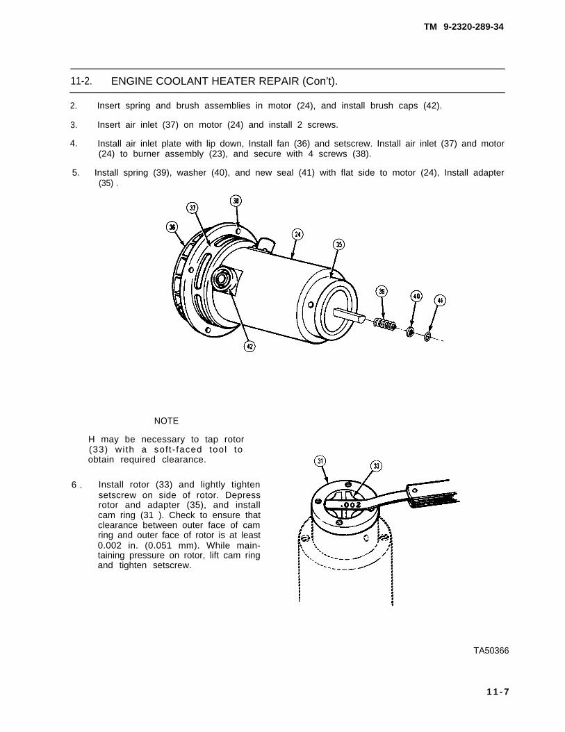
TM 9-2320-289-34
11-2. ENGINE COOLANT HEATER REPAIR (Con’t).
2. Insert spring and brush assemblies in motor (24), and install brush caps (42).
3. Insert air inlet (37) on motor (24) and install 2 screws.
4. Install air inlet plate with lip down, Install fan (36) and setscrew. Install air inlet (37) and motor(24) to burner assembly (23), and secure with 4 screws (38).
5. Install spring (39), washer (40), and new seal (41) with flat side to motor (24), Install adapter(35) .
NOTE
H may be necessary to tap rotor(33) with a soft- faced tool toobtain required clearance.
6 . Install rotor (33) and lightly tightensetscrew on side of rotor. Depressrotor and adapter (35), and installcam ring (31 ). Check to ensure thatclearance between outer face of camring and outer face of rotor is at least0.002 in. (0.051 mm). While main-taining pressure on rotor, lift cam ringand tighten setscrew.
TA50366
1 1 - 7

TM 9-2320-289-34
11-2. ENGINE COOLANT HEATER REPAIR (Con’t).
7. With motor (24) standing on end,install vanes (32) in rotor (33) withnotches horizontal. Install new “O“ring (30) and cam ring (31) toadapter (35).
8. Install new “O“ ring and port plate(26), alining mark/scribe, and install4 screws (25).
9. Install motor (24) and burner unit onheat exchanger (29) and connectcoolant hoses (27). Feed motor leadthrough grommet in burner case(19).
10. Install burner case (19) over motor (24) and burner unit, and secure with 4 screws (21). Install4 screws (22) to 2 halves of case.
11. Coat threads with antiseize tape and install fuel fitting (12) and elbow in top of burner assembly(23) with nipple facing toward grommet.
12. Install air inlet cover (20) and secure with 8 screws. Install limit switch (8) with 2 screws.
TA50367
11-8

TM 9-2320-289-34
11-2. ENGINE COOLANT HEATER REPAIR (Con’t).
13.
14.
15.
16.
17.
Install new gasket to igniter (16) and install igniter. Connect lead to igniter. Install new watercoolant fittings (9) if removed,
Position fuel control (1) in fuel control bracket (2) if removed and install screw. Install fuelcontrol bracket on case with 4 screws. Position thermostat valve (2) to thermostat bracket andinstall screw.
Connect lead from thermostat valve (18) and lead from igniter to limit switch (8).
Install fuel hose (4) and tighten 2 clamps (3). Install flame switch (7) and tighten nut.
Position terminal block (6) on case with 2 screws. Install relay assembly (17) and 2 screws.
TA50368
11-9

TM 9-2320-289-34
11-2. ENGINE COOLANT HEATER REPAIR (Con’t).
18.
19.
20.
21.
22.
Install timer (15), backing plate, nut, bolt (14), and new Iockwasher. Install electricalreceptacle (11) and secure with 4 screws (5). Install lead and terminal block retaining screw.
Connect all remaining electrical leads. Solder pink/black lead at tagged terminal on relayassembly (17).
Install clamp (13) and mounting bracket.
Adjust flame switch (7). (See FLAME SWITCH ADJUSTMENT)
Install cover and tighten screws.
TA50369
11-10

TM 9-2320-289-34
11-2. ENGINE COOLANT HEATER REPAIR (Con’t).
d . FLAME SWITCH ADJUSTMENT
NOTE
● If new flame switch (7) has been installed. no adjustment is required.
● if adjustment nut (10) has been disturbed, perform steps 1-4.
● Ensure that heater is off and at ambient temperature prior to flameswitch (7) adjustment,
1. Turn spring loaded screws securing cover 1/4 turn and remove cover.
2. Turn nut (10) on adjustment screw on switch bracket counterclockwise until blower fan comeson.
3. Very slowly, turn nut (10) clockwise until blower fan turns off, Note position of nut.
4. Turn nut (10) clockwise an additional 180 degrees from noted position, Seal nut with insulatingvarnish.
FOLLOW-ON TASKS:
● Install engine coolant heater. (See TM 9-2320-289-20)
11-11

TM 9-2320-289-34
11-3. WARM AIR HEATER REPAIR.
This task covers: a. Disassembly c . Assemblyb. Cleaning and Inspection d. Flame Detector Switch
Adjustment
INITIAL SETUP:
Equipment Condition Materials/Parts
● Warm air heater removed. • One gasket(See TM 9-2320-289-20) • One preformed packing ring
● Insulating varnish(Item 71, Appendix B)
a . DISASSEMBLY
NOTE
Ensure that all terminals and leads are tagged for assembly.
1. Turn 2 fasteners (4) and remove cover (2) from heater housing (3). Disconnect all leads.
2. Remove harness (7) from electrical receptacle (5). Remove 4 screws (6) and electricalreceptacle.
3. Remove 4 screws (9), 1 nut (13), 1 starwasher (14), and ignition control (8) from heaterhousing (3). Pull leads through clip.
4 . Disconnect fuel line nut (11) from outlet of fuel control valve (10). Remove screws and fuelcontrol valve from heater housing (3).
5. Remove screws and overheat switch (15) from heater housing (3).TA50370
11-12

TM 9-2320-289-34
11-3. WARM AIR HEATER REPAIR (Con’t).
6. Unscrew nut at base of flame detector switch (17) until it clears threads and carefully removeswitch from heat exchanger housing.
7. Loosen 4 screws (18) around edge ofblower assembly (1). Turn blowerassembly counterclockwise to freefrom screws and remove blowerassembly and lead.
8 . Disconnect igniter ground lead fromhatch cover (12). Turn fasteners andremove hatch cover.
TA50371
11-13

TM 9-2320-289-34
11-3. WARM AIR HEATER REPAIR (Con’t).
9 .
10.
11.
12.
13.
Twist igniter assembly (22) to disengage lugs from slots and remove from igniter tube (20).
Remove screw (21) and igniter tube (20).
Release fuel line nut from burner bushing (26) and remove secondary blower housing (19).Remove heater housing (3) ground lead,
NOTE
Ensure that position of burner assembly
Remove nuts, clamps, and hook bolts holdinghousing.
Remove and discard gasket (25) and preformed
(23) is marked for assembly,
burner assembly (23) to heat exchanger
packing ring (24).
1 . Clean all mating surfaces.
b. CLEANING AND INSPECTION
2 . Clean all carbon from burner assembly. Inspect all holes, ports, and passageways, andremove any obstructions.
TA50372
11-14

TM 9-2320-289-34
11-3. WARM AIR HEATER REPAIR (Con’t).
3 . Clean all carbon from igniter.
4. Clean any accumulation of dirt from case.
5 . Inspect all leads for damage, Inspect connectors for looseness or corrosion. Replace if any ofthese conditions exist.
6 . Inspect rod located under flame detector switch. If rod is broken, replace flame detectorswitch.
7 . Inspect burner assembly and heat exchanger for damage or burn through. Replace if damagedor burnt through.
8. Inspect blower assembly for damage. Replace if damaged.
9. Inspect fuel control valve for damage. Replace if damaged.
c . ASSEMBLY
1. Install new preformedassembly (23).
2 . Place burner assemblyand nuts into position.
packing ring (24) and new gasket
(23) in heat exchanger housing, and
(25) over burner end of burner
loosely install hook bolts, clamps,
3. Aline burner assembly (23) to large access hole in heater housing (3). Install ground lead andtighten hook bolts, clamps, and nuts.
4. Install secondary blower housing (19) in burner assembly (23), and aline access opening withlarge hole of heater housing (3). Firmly seat in place.
5. Install fuel line through secondary blower housing (19) access tube, Connect fuel line nut ontoburner bushing (26) and tighten connection.
6. Install igniter tube (20) into igniter chamber with screw (21). Install igniter assembly (22) andpress against spring to engage bayonet fastener.
11-15

TM 9-2320-289-34
11-3. WARM AIR HEATER REPAIR (Con’t),
7 . Install hatch cover (12) and securefasteners. Connect igniter groundlead to hatch cover.
8. Thread blower lead through hole inheater housing (3), Install blowerassembly (1) into blower housing andslide slots under 4 screws (18).Tighten screws.
9. Install overheat switch (15) and secure with screws.
10. Install flame detector switch (17) into heat exchanger housing with nut and sleeve. Positionadjuster nut (16) above overheat switch.
11. Adjust flame detector switch (17) . (See FLAME DETECTOR SWITCH ADJUSTMENT)
TA50373
11-16

TM 9-2320-289-34
11-3. WARM AIR HEATER REPAIR (Con’t).
12. Install fuel control valve (10) and screws to heater housing (3), Connect fuel line nut (11) tooutlet of fuel control valve.
13. Install ignition control (8) to heater housing (3) using 4 screws (9), 1 nut (13), and 1starwasher (14),
14. Install electrical receptacle (5) and 4 screws (6) to bracket. Connect all leads.
15. Connect harness (7) to electrical receptacle (5). Install cover (2) to heater housing (3) andsecure 2 fasteners (4).
d. FLAME DETECTOR SWITCH ADJUSTMENT
●
●
●
NOTE
If new flame detector switch (17) has been installed, no adjustment isrequired.
If adjuster nut (16) has been disturbed, perform steps 1-3.
Ensure that heater is off and at ambient temperature prior to flamedetector switch (17) adjustment.
1. Back off adjuster nut (16) two turns.
2 . Turn adjuster nut (16) inward slowly justadditional 3/4 in. (19 mm) turn from “click”
until switch “clicks.” Then turn adjuster nut anposition.
3. Apply insulating varnish to adjuster nut (16) to seal.
FOLLOW-ON TASKS:
● Install warm air heater. (See TM 9-2320-289-20)• Check operation of heater.
TA50374
11-17/(11-18 blank)

TM 9-2320-289-34
APPENDIX AREFERENCES
A-1 . SCOPE.
This appendix lists all forms, field manuals, technical manuals, and other publicationsrequired for use with this manual.
A-2. INDEXES.
The following indexes should be frequently consulted for latest changes to, or revisions of,references given in this appendix and for new publications or instructions relating to materiel covered inthis manual.
a. Military Publications:
Consolidated Index of Army Publications and Blank Forms . . . DA Pam 25-30Equipment Improvement Report and Maintenance Digest . . . . TB 43-0001-39The Standard Army Publications System Users Index , . . . . . . . DA Pam 310-10
b. General References:
Catalog of Abbreviations and Brevity Codes . . . . . . . . . . . . . . . AR 310-50Dictionary of United States Army Terms . . . . . . . . . . . . . . . . . . AR 310-25Military Symbols . . . . . . . . . . . . . . . . . . . . . . . . . . . . . . . . . . . . . . FM 101-5-1
A-3. SUPPLY CATALOGS.
The following Department of the Army Supply Catalogs pertain to this manual:
Shop Equipment, Automotive Maintenance and Repair:Field Maintenance: Basic, Less Power(NSN 4910-00-754-0705) . . . . . . . . . . . . . . . . . . . .
Shop Equipment, Automotive Maintenance and Repair:Field Maintenance: Supplemental No. 1, Less Power(NSN 4910-00-754-0706) . . . . . . . . . . . . . . . . . . . . . . . . . . . . .
Shop Equipment, Automotive Maintenance and Repair:Organizational Maintenance: Common No. 1, Less Power(NSN 4910-00-754-0654) . . . . . . . . . . . . . . . . . . . . . . . . . . . . .
Shop Equipment, Automotive Maintenance and Repair:Organizational Maintenance: Supplemental No. 1,Less Power (NSN 4910-00-754-0653) . . . . . . . . . . . . . . . . . . .
Shop Equipment, Automotive Maintenance and Repair:Organizational Maintenance: Common No. 2, Less Power(NSN 4910-00-754 -0650) . . . . . . . . . . . . . . . . . . . . . . . . . . . . .
SC 4910-95-CL-A31
SC 4910-95-CL-A62
SC 4910-95-CL-A74
SC 4910-95-CL-A73
SC 4910-95-CL-A72
Change 1 A-1

TM 9-2320-289-34
Tool Kit, General Mechanic’s: Automotive(NSN 5180 -00-177 -7033 ) . . . . . . . . . . . . . . . . . . . . . . . . . . . . . SC 4910-95-N26
Tool Kit, Welder’s (NSN 5180-00-754-0661) . . . . . . . . . . . . . . . SC 5180-90-CL-N39
A-4. FORMS.
Refer to DA Pam 25-30, Consolidated Index of Army Publications and Blank Forms, for acurrent and complete list of blank forms. Refer to DA Pam 738-750, The Army MaintenanceManagement System (TAMMS), for instructions on the use of maintenance forms pertaining to thismateriel.
DA Form 285 . . . . . . . . . . . . . . . . . . . . . . . . . . . US Army Accident Investigation ReportDA Form 348 . . . . ... Equipment Operator’s Qualification Record (Except Aircraft)DA Form 2028 . . . . . . . . . . . Recommended Changes to Publications and Blank FormsDA Form 2401 . . . . . . . . . . . . . . . . . . . . . . . Organization Control Record for EquipmentDA Form 2402 . . . . . . . . . . . . . . . . . . . . . . . . . . . . . . . . . . . . . . . . . . . . . . . Exchange TagDA Form 2404 . . . . . . . . . . . . . . . . Equipment Inspection and Maintenance WorksheetDA Form 2405 . . . . . . . . . . . . . . . . . . . . . . . . . . . . . . . . . Maintenance Request RegisterDA Form 2406 . . . . . . . . . . . . . . . . . . . . . . . . . . . . . . . . Materiel Condition Status ReportDA Form 2407 . . . . . . . . . . . . . . . . . . . . . . . . . . . . . . . . . . . . . . . . . Maintenance RequestDA Form 2407-1 . . . . . . . . . . . . . . . . . . . . . Maintenance Request -Continuation SheetDA Form 2408 . . . . . . . . . . . . . . . . . . . . . . . . . . . . Equipment Log Assembly (Records)DA Form 2408-9 . . . . . . . . . . . . . . . . . . . . . . . . . . . . . . . . . . . Equipment Control Record
DA Form 2409 . . . . . . . . . . . . . . . . . . . . . . Equipment Maintenance Log (Consolidated)DDForm 314 . . . . . . . . . . . . . . . . . . . . . Preventive Maintenance Schedule and RecordDDForm 518 . . . . . . . . . . . . . . . . . . . . . . . . . . . . . . . . . . . . . Accident Identification CardDDForm 1397 . . . . . . . . . . . . . . . Processing and Reprocessing Record for Shipment,
Storage, and issue of Vehicles and Spare EnginesStandard Form 46 . . . . . US Government Motor Vehicle Operator’s Identification CardStandard Form 91, . . . . . . . . . . . . . . . . . Operator Report on Motor Vehicle AccidentsStandard Form 368 . . . . . . . . . . . . . . . . . . . . . . . . . . . . . . . . . . Quality Deficiency Report
A-5. OTHER PUBLICATIONS.
The following publications contain information pertinent to the major item materiel andassociated equipment.
a. Truck:
Lubrication Order for Truck,3/4 and 1 1/4 Ton, 4x4, CUCV Series . . . . . . . . . . . . . . . . . . . . . LO 9-2320-289-12
Operator’s Manual for Truck,3/4 and 1 1/4 Ton, 4x4, CUCV Series . . . . . . . . . . . . . . . . . . . . . TM 9-2320-289-1 O
Unit Maintenance Manual for Truck,3/4 and 1 1/4 Ton, 4x4, CUCV Series . . . . . . . . . . . . . . . . . . . . . TM 9-2320-289-20
Unit Maintenance Repair Parts and Special Tools List for Truck,3/4 and 1 1/4 Ton, 4x4, CUCV Series . . . . . . . . . . . . . . . . . . . . . TM 9-2320-289-20P
A-2 Change 1

TM 9-2320-289-34
Intermediate DS/GS Maintenance Repair Parts andSpecial Tools List for Truck,3/4 and 1 1/4 Ton, 4x4, CUCV Series.. . . . . . . . . . . . . . . . . . . . TM 9-2320-289-34P
Warranty Procedures for Truck,3/4 and 1 1/4 Ton, 4x4, CUCV Series . . . . . . . . . . . . . . . . . . . . . TB 9-2300-295-15/24
b. Camouflage:
Camouflage . . . . . . . . . . . . . . . . . . . . . . . . . . . . . . . . . . . . . . . . . . FM 5-20Camouflage Materials . . . . . . . . . . . . . . . . . . . . . . . . . . . . . . . . . . TM 5-200Color, Marking, and Camouflage Painting of Military
Vehicles, Construction Equipment, and MaterialsHandling Equipment . . . . . . . . . . . . . . . . . . . . . . . . . . . . . . . . TB 43-0209
c. Decontamination:
NBC Decontamination . . . . . . . . . . . . . . . . . . . . . . . . . . . . . . . . . FM 3-5Chemical, Toxicological, and Missile Fuel Handlers
Protective Clothing . . . . . . . . . . . . . . . . . . . . . . . . . . . . . . . . . . . TM 10-277Operator’s and Organizational Maintenance Manual
(Including Repair Parts and Special Tools List) forDecontamination Apparatus, Portable, DS2,1 1/4 Quart, ABC-M11 (NSN 4230-00-720-1618) . . . . . . . . . . . . TM 3-4230-204-12&P
d. General:
Accident Reporting and Records . . . . . . . . . . . . . . . . . . . . . . . . . AR 385-40Army Motor Transport Units and Operations . . . . . . . . . . . . . . . FM 55-30Basic Cold Weather Manual . . . . . . . . . . . . . . . . . . . . . . . . . . . . . FM 31-70Chemical Agent Resistant Aliphatic Polyurethane Coating . . . . MIL-C-46168CCooling Systems: Tactical Vehicles . . . . . . . . . . . . . . . . . . . . . . TM 750-254
Corrosion Prevention and Control: IncludingRustproofing for Tactical Vehicles and Trailers . . . . . . . . . . . .
First Aid for Soldiers . . . . . . . . . . . . . . . . . . . . . . . . . . . . . . . . . . .Functional Grouping Codes: Combat, Tactical, and Support
Vehicles and Special Purpose Equipment . . . . . . . . . . . . . . . .General Repair for Clothing and Textiles . . . . . . . . . . . . . . . . . .Manual for the Wheeled Vehicle Driver . . . . . . . . . . . . . . . . . . .Mountain Operations . . . . . . . . . . . . . . . . . . . . . . . . . . . . .Northern Operations. . . . . . . . . . . . . . . . . . . . . . . . . . . . .Operation and Maintenance of Ordnance Materiel
in Cold Weather (10°F to-65°F) . . . . . . . . . . . . . . . . . . . . . . . .Painting instructions for Field Use. . . . . . . . . . . . . . . . . . . . . . . .Painting Procedures and Marking for Vehicles, Construction
Equipment and Material Handling Equipment . . . . . . . . . . . . .Petroleum Supply Point Equipment and Operations . . . . . . . . .Prevention of Motor Vehicle Accidents . . . . . . . . . . . . . . . . . . . .Principles of Automotive Vehicles . . . . . . . . . . . . . . . . . . . . . . . .Procedures for Destruction of Tank-Automotive Equipment
to Prevent Enemy Use . . . . . . . . . . . . . . . . . . . . . . . . . . . . . . . .Treatment and Painting of Materiel . . . . . . . . . . . . . . . . . . . . . . .
TB 43-0213FM 21-11
TB 750-93-1FM 10-16
FM 21-305FM 90-6
FM 31-71
FM 9-207TM 43-0139
MlL-STD-193FM 10-69
AR 385-55TM 9-8000
TM 750-244-6MIL-T-704J
Change 2 A - 3

TM 9-2320-289-34
e. Maintenance and Repair:
Chemical Agent Alarm Maintenance . . . . . . . . . . . . . . . . . . . . . .Description, Use, Bonding Techniques
and Properties of Adhesives. . . . . . . . . . . . . . . . . . . . . . . . . . .Inspection, Care, and Maintenance of Antifriction Bearings , . .Mandatory Brake Hose Inspection and
Replacement - Tactical Vehicles . . . . . . . . . . . . . . . . . . . . . . .Materials Used for Cleaning, Preserving, Abrading and
Cementing Ordnance Materiel and Related MaterialsIncluding Chemicals . . . . . . . . . . . . . . . . . . . . . . . . . . . . . . . . . .
Metal Body Repair and Related Operations . . . . . . . . . . . . . . . .Operator’s and Organizational Maintenance Manual:
Alarm, Chemical Agent, Automatic . . . . . . . . . . . . . . . . . . . . Operator’s and Organizational Maintenance Manual Including
Repair Parts and Special Tools List for Simplified TestEquipment for Internal Combustion Engines (STE/lCE) ., . . .
Operator’s Manual for Welding Theory and Application . . . . . .Operator’s, Organizational, Direct Support and General
Support Maintenance Manual for Lead-AcidStorage Batteries . . . . . . . . . . . . . . . . . . . . . . . . . . . . . . . .
Organizational Care, Maintenance & Repair of Pneumatic Tires,inner Tubes and Radial Tires., . . . . . . . . . . . . . . . . . . . . . . . . .
TM 3-6665-225-12
TB ORD 1032TM 9-214
TB 9-2300-405-14
TM 9-247FM 43-2
TM 3-6665-261-14
TM 9-4910-571-12&PTM 9-237
TM 9-6140-200-14
TM 9-2610-200-24
Safety Inspection and Testing of Lifting Devices . . . . . . . . . . . . TB 43-0142Standards and Criteria for Technical Inspection
and Classification of Tires. . . . . . . . . . . . . . . . . . . . . . . . . . . . . TM 9-2610-201-14Tactical Wheeled Vehicles: Repair of Frames . . . . . . . . TB 9-2300-247-40Use of Antifreeze Solutions and Cleaning Compounds
in Engine Cooling Systems. . . . . . . . . . . . . . . . . . . . . . . . . . . . TB 750-651
f. Shipment and Limited Storage:
Marking for Shipment and Storage . . . . . . . . . . . . . . . . . . . . . . . MlL-STD-129Methods of Preservation . . . . . . . . . . . . . . . . . . . . . . . . . . . . . . . . MlL-P-116Packaging of Materiel . . . . . . . . . . . . . . . . . . . . . . . . . . . . . . . . . . AR 700-15Packaging of Materiel: Preservation . . . . . . . . . . . . . . . . . . . . . . TM 38-230-1
and TM 38-230-2Preparation for Shipment and Limited Storage
of Wheeled Vehicles . . . . . . . . . . . . . . . . . . . . . . . . . . . . . . . . . MIL-V-62038Preparation for Shipment and Storage of Basic Issue Items
for Military Vehicles, Carriages and Equipment . . . . . . . . . . MlL-B-12841
Railcar Loading Procedures . . . . . . . . . . . . . . . . . . . . . . . . . . . . . TM 55-601Security of Tactical Wheeled Vehicles . . . . . . . . . . . . . . . . . . TB 9-2300-422-20Softwood Lumber . . . . . . . . . . . . . . . . . . . . . . . . . . . . . . . . . . . . . MM-L-751Standards for Overseas Shipment or Domestic Issue of
Special Purpose Vehicles, Combat, Tactical, Construction,and Selected Industrial and Troop Support US ArmyTank-Automotive Readiness Command Managed Items . . . . . TB 9-2300-281-35
A-4 Change 1

TM 9-2320-289-34
APPENDIX BEXPENDABLE/DURABLE SUPPLIES AND MATERIALS LIST
Sect ion 1. INTRODUCTION
B-1. SCOPE.
This appendix lists expendable/durable supplies and materials you will need to maintain theCUCV Series trucks. This listing is for informational purposes only and is not authority to requisitionthe listed items. These items are authorized to you by CTA 50-970, Expendable/Durable Items(Except Medical, Class V, Repair Parts, and Heraldic Items), or CTA 8-100, Army MedicalDepartment Expendable/Durable Items.
B-2. EXPLANATION OF COLUMNS.
a. Column (1) - Item Number. This number is assigned to the entry in the listing and isreferenced in the Initial Setup of applicable tasks under the heading of Materials/Parts.
b. Column (2) - Level. This column identifies the lowest level of maintenance thatrequires the listed item.
C - Operator/CrewO - Unit MaintenanceF - Intermediate Direct Support MaintenanceH - Intermediate General Support Maintenance
c. Column (3) - National Stock Number. This is the National Stock Number assigned tothe item; use it to request or requisition the item.
d. Column (4) - Description. Indicates the Federal item name and, if required, adescription to identify the item. The last line for each item indicates the Federal Supply Code forManufacturer (FSCM) in parentheses, followed by the part number, if applicable.
e. Column (5) - Unit of Measure (U/M). Indicates the measure used in performing theactual maintenance function. This measure is expressed by an alphabetical abbreviation (e. g., ea,in, pr, gal), If the unit of measure differs from the unit of issue, requisition the lowest unit of issuethat will satisfy your requirements.
B-1

TM 9-2320-289-34
S e c t i o n I l . E X P E N D A B L E / D U R A B L E S U P P L I E S A N DM A T E R I A L S L I S T - C o n t i n u e d
(1) (2) (3) (4) (5)
Item NationalNumber Level Stock Number Description U/M
1. F 6810-00-184-4796 ACETONE: OZ(81348) Q-A-51
2. 0 5935-00-322-8959 ADAPTER: Connector ea(19207) 11677570
2.1. 0 8040-00-024-6991 ADHESIVE: lnterlor Rearview Mirror ea(11862) 1052369
3. 0 9150-01-198-3829 ADDITIVE: Differential 0 z(11862) 1052358
4. 0 8040-00-262-9028 ADHESIVE: General Purpose, Type 1 p t(19203)829899
5. F 8040-01-024-6991 ADHESIVE: Loctlte, Minute Bond S12 p t(11862) 1052369
6. F ALCOHOL: Denatured(81348)o-E-00760
6810-00-205-6790 4 Ounce Bottle 0z6810-00-205-6786 1 Quart Bottle q t6810-00-782-2686 1 Gallon Bottle g a l
7. c ANTIFREEZE: Arctic(81349) MIL-A-11755
6850-00-174-1806 55 Gallon Drum gal
8. c ANTIFREEZE: Ethylene Glycol, Inhibited, Heavy-duty,Single Package (81349) MIL-A-46153
6850-00-181-7929 1 Gallon Can gal6050-00-181-7933 5 Gallon Can gal6850-00-181-7940 55 Gallon Drum gal
9. 0 BARRIER MATERIAL: Greaseproof(81349) MIL-B-121
8135-00-171-0930 100 Yard Roll yd
10. 0 BRAKE FLUID: Silicone, Automotive, All Weather,Operational and Preservative, (81349) MIL-B-46176
9150-01-102-9455 1 Gallon Can gal
9150-01-123-3152 5 Gallon Can gal
9150-01-072-8379 55 Gallon Drum gal
11. 0 2590-00-398-6527 CABLE: 20 Feet, without Connectors e a(19207) 11682337-1
12. 0 6150-01-022-6004 CABLE: with End Connectors ea(19207) 11682336-1
B-2 Change 2

TM 9-2320-289-34
Section I l . EXPENDABLE/DURABLE SUPPLIES ANDMATERIALS LIST - Continued
(1) (2) (3) (4) (5)
Item NationalNumber Level Stock Number Description U/M
13. F 4910-00-779-6651 CALIBRATION FLUID: qt(33267) J-26400-5
14. 0 CHALK, MARKING:(81348) SS-C-225
7510-00-223-6701 1 Gross gr
15. F 6850-01-085-1423 CLEANING COMPOUND: Carburetor 02(56921) CARB-N-RLD
16. c CLEANING COMPOUND: Windshield Washer(81348) O-C-1901
6850-00-926-2275 1 Pint Bottle pt
17. F CLOTH: Abrasive(81348) P-C-451
5350-00-187-6294 50 Yard Roll yd
18. F CLOTH: Abrasive, Crocus(81348) P-C-456
5350-00-221-0872 50 sheets sh
19. 0 COATING: Aliphatic Polyurethane, Chemical AgentResistant, Forest Green (81 349) MIL-C-46168C
8010-00-111-7937 1 Gallon Can gal8010-00-111-8010 5 Gallon Can gal
20. 0 2510-00-567-0128 CONNECTOR PLUG:(19207) 11682338 ea
21. 0 CORROSION PREVENTIVE COMPOUND:(81349) MlL-C-11796
8030-00-231-2354 5 Pound Carton lb
22. c DETERGENT: General Purpose, Liquid(81349) MIL-D-16791
7930-00-282-9699 1 Gallon Can gal
23. c DRY CLEANING SOLVENT: Type II(81348) P-D-680
6850-00-110-4498 1 Pint Can pt6850-00-274-5421 5 Gallon Can gal6850-00-285-8011 55 Gallon Drum gal
B - 3

TM 9-2320-289-34
S e c t i o n I l . E X P E N D A B L E / D U R A B L E S U P P L I E S A N DM A T E R I A L S L I S T - C o n t i n u e d
(1) (2) (3) (4) (5)
Item NationalNumber Level Stock Number Description U / M
24. F DYE: Prussian Blue(81 349) MIL-P-30501
8010-00-889-9745 1 Ounce Tube 0z
25. c FUEL OIL DIESEL: Arctic, DF-A(81 348) VV-F-800
9140-00-286-5282 5 Gallon Can g a l9140-00-288-5284 55 Gallon Can g a l
26. c FUEL OIL DIESEL: Regular, DF-2(81346) VV-F-800
9140-00-266-5295 5 Gallon Can gal9140-00-266-5296 55 Gallon Can gal
27. c FUEL OIL DIESEL: Winter, DF-1(61348) VV-F-800
9140-00-286-5287 5 Gallon Can ga l9140-00-286-5288 55 Gallon Can ga l
28. 0 5920-01-123-5212 FUSE: 5 amp ea(11862) 12004005
29. 0 5920-01-123-5211 FUSE: 10 amp ea(11662) 12004007
30. 0 5920-01-149-6952 FUSE: 15 amp ea(11662) 12004008
31. 0 5920-01-085-0825 FUSE: 20 amp ea(11862) 12004009
32. 0 5920-01-149-6953 FUSE: 25 amp e a(11862) 12004010
33. 0 5920-01-188-6294 FUSE: 30 amp e a(11862) 12004011
34. 0 5210-01-222-8068 GAGE: Plast ic Adjustment ea(11662) 14061396
35. F 5210-00-640-6177 GAGING PLASTIC: Green e a(77220) PG-1
B-4

TM 9-2320-289-34
S e c t i o n I l . E X P E N D A B L E / D U R A B L E S U P P L I E S A N DM A T E R I A L S L I S T - C o n t i n u e d
(1) (2) (3) (4) (5)
Item NationalNumber Level Stock Number Description U/M
36. c GREASE: Automotive and Artillery[61349) MIL-G-10924
9150-00-935-1017 14 Ounce Cartridge 029150-00-190-0904 1-314 Pound Can lb9150-00-190-0905 6-1/2 Pound Can lb
37. 0 GREASE: Molybdenum, Disulfide(61346) MIL-Q-21164
9150-00-935-4016 6 Ounce Tube 02
38. F 4720-01-156-0547 HOSE: Rubber, 5/16 Inch I.D. ft(11662) 9439104
39. H 4720-01-156-0548 HOSE: Rubber, 3/8 1nchl. D, ft(11662) 9439162
40. c HYDRAULIC FLUID: Transmission(2461 7) Dexron ® II
9150-00-698-2382 1 Quart Can qt9150-00-657-4959 5 Gallon Can gel
41. c INHIBITOR: Corrosion, Liquid Cooling Syetem(81349) MIL-A-53009
6850-00-160-3868 1 Quart Can qt
42. H 9150-01-041-6649 LUBRICANT: “O” Ring 02(71984) DC 111
43. c LUBRICATING OIL: Gear, Multipurpose, GO 75W(81349) MIL-L-2105
9150-01-035-5390 1 Quart Can qt9150-01-035-5391 1 Qallon Can gal
44. c LUBRICATING OIL: Gear, Multipurpose, GO BO/90(81349) MIL-L-2105
9150-01-035-5392 1 Quart Can qt9150-01-035-5393 1 Gallon Can gal
45. c LUBRICATING OIL: General Purpose, Preservative, PL-S(61 348) V-VL-800
9150-00-231-6669 1 Quart Can qt
B-5

TM 9-2320-289-34
Section I l . EXPENDABLE/DURABLE SUPPLIES ANDMATERIALS LIST - Continued
(1) (2) (3) (4) (5)
Item NationalNumber Level Stock Number Description U/M
46. c LUBRICATING OIL: Internal Combustion Engine,Arctic, OEA (81349) MIL-L-46167
9150-00-402-4478 1 Quart Can q t9150-00-402-2372 5 Gallon Can ga l9150-00-491-7197 55 Gallon Drum ga l
47. c LUBRICATING OIL: Internal Combustion Engine,Tactical Service, OE/HDO 10 (81349) MIL-L-2104
9150-00-189-6727 1 Quart Can q t9150-00-186-6668 5 Gallon Can gal9150-00-191-2772 55 Gallon Drum gal
48 . c LUBRICATING OIL: Internal Combustion Engine,Tactical Service, OE/HDO 15W/40 (81349) MIL-L-2104
9150-01-152-4117 1 Quart Can q t9150-01-152-4118 5 Gallon Can gal9150-01-152-4119 55 Gallon Drum gal
49. c LUBRICATING OIL: Internal Combustion Engine,Tactical Service, OE/HDO 30 (81349) MIL-L-2104
9150-00-186-6681 1 Quart Can q t9150-00-188-9858 5 Gallon Can gal9150-00-189-6729 55 Gallon Drum gal
50. F 6505-00-133-8060 PETROLATUM: white o z
51. 0 PRESERVATIVE COMPOUND:(331 50) x975
8030-01-220-1442 4 Ounce with Spray o z8030-01-220-1441 8 Ounce with Spray o z8030-01-220-1440 32 Ounce Bottle o z
52. 0 PRIMER: Epoxy Coating(81349) MIL-P-521928
8010-00-264-8866 K i t e a
53. c RAG: Wiping, Cotton and Cotton-Synthetic(58536) A-A-531
7920-00-205-1711 50 Pound Bale l b
54. F 6830-00-935-9895 REFRIGERANT: R-12 o z(11862) 1051053
B-6

TM 9-2320-289-34
Section I l . EXPENDABLE/DURABLE SUPPLIES ANDMATERIALS LIST - Continued
(1) (2) (3) (4) (5)
Item Nationallumber Level Stock Number Description U/M
55. F 9150-01-160-026 REFRIGERANT OIL: 02(11862) 5416939
56. H 5330-00-151-6659 SEALANT: Gasket Forming 02(77247) 98D
57. 0 SEALANT: Silicone, RTV(1 1862) 1052734
8030-01-159-4644 8-1/2 Ounce Tube 02
58. F 8030-00-252-3391 SEALING COMPOUND: 02(61349) MIL-S-45180
59. F 8030-01-156-6209 SEALING COMPOUND: Anaerobic 02(11862) 1052357
60. 0 SEALING COMPOUND: Corrosion-resistant, Type II(81349) MIL-S-81733
8030-00-009-5023 Kit ea
61. 0 SEALING COMPOUND: Pipe, Anaerobic, with Teflon(05972) 592-31
8030-01-054-0740 50 Mililiter Tube ml
62. H 3439-00-247-6921 SOLDER: Lead in(81348) QQ-S-571
63, 0 STRAP: Tie-down(06383) MS 3367-1-9
5975-00-074-2072 Box of 100 ea
64. 0 9905-00-537-8954 TAG: Marker, 50 Each ea(81349) MIL-T-12755
65. 0 TAPE: Antiseize, 1/2 inch width(81349) MIL-T-27730A
8030-00-889-3535 260 Inch Roll in
66. 0 TAPE: Duct, 21 nch width(07124) C-519
5640-00-103-2254 60 Yard Roll yd
67. F 5640-00-580-6276 TAPE: Insulation, Thermal f t(73030) MS 7495-618
B-7

TM 9-2320-289-34
Section I l . EXPENDABLE/DURABLE SUPPLIES ANDMATERIALS LIST - Continued
(1) (2) (3) (4) (5)
Item Nationaldumber Level Stock Number Description U / M
68. 0 TAPE: Pressure Sensitive Adhesive, Masking, Flat,2 inch width (81349) MIL-T-2397
7510-00-473-9513 60 Yard Roll yd
68.1 0 TAPE: Pressure Sensitive Adhesive, Red, Flat,1/2 inch width (52170) 650
7510-00-550-7126 72 Yard Roll yd
69. 0 4720-00-964-1433 TUBE: Plastic Drain, Type 1, Class A, Grade 4 ft(61346) D1248-60T
70. 0 TWINE: Fibrous, Cotton (String), 16-Ply(81 348) T-T-871
4020-00-291-5901 375 Yard Spool yd
71. F 8010-00-298-3870 VARNISH: Insulating qt(81349) MIL-V-13811
B - 8 Change 2

TM9-2320-289-34
APPENDIX CILLUSTRATED LIST OF MANUFACTURED ITEMS
Section 1. INTRODUCTION
C-1. SCOPE.
a. This appendix includes complete instructions for making items authorized to bemanufactured or fabricated at intermediate direct support and general support maintenance.
b. A part number index in alphanumeric order is provided for cross-referencing the partnumber of the item to be manufactured to the figure which covers fabrication criteria.
All bulk materials needed for manufacture of an item are listed by National Stock Number(NSN), part number, or specification number in the manufacturing instructions.
d. All dimensions given in Section II, Illustrated Manufacturing Instructions, are in inches,except as noted.
Table C-1. Manufactured Items Part Number Cross-reference
PART FIGURE PART FIGURE PARTNUMBER NUMBER
FIGURENUMBER NUMBER NUMBER NUMBER
FLW-12 c-7 14036712 C-17 14072372 C-19FLW-16 C-6 14036797 C-16 15522444 C-14FLW-18 C-4 14040735 C-18FLW-20 C-5 14045626 C-10 15599259 C-1314029235 C-1 1 14045628 c-lo 15599260 C-1214034571 C-15 14054275 C-15 15599261 C-1314034572 C-15 14061503 C-1 15599262 C-1214034586 C-14 14063323 C-19 31-0040 C-1914034599 C-16 14063339 C-2 31-0040A C-1914036705 C-17 14072369 C-1914036706 C-17 14072371 C-19 8906127 C-314036711 C-17
Change 2 C-1/(C-2 BLANK)


TM 9-2320-289-34
Section Il. ILLUSTRATED MANUFACTURING INSTRUCTIONS
1 . Fabricate from steel tubing, 3/8 in, outside diameter, stock size 25 ft. long,NSN 4720-01-158-7511.
2 . Cut to 35.52 in. long for Part Number 14061503.
3 . Install nut, NSN 4730-00-013-7399, Part Number 137339, on each end oftubing.
4 . Flare ends of tubing. Nuts should turn freely on flares.
5 . Use old pipe as a guide and bend steel tubing to same shape,
Figure C-1. Fuel Pump Pipe
C-3

TM 9-2320-289-34
Section Il. ILLUSTRATED MANUFACTURING INSTRUCTIONS -Continued
TA50150
C-4

TM 9-2320-289-34
Sect ion I l . ILLUSTRATED MANUFACTURING INSTRUCTIONS-
1.
2.
3.
4.
1.
2.
1.
2.
1.
2.
1.
2.
Cont inued
Fabricate from steel tubing, 1/4 in. outside diameter, stock size 25 ft. long,NSN 4720-01-161-0138.
Cut to 2.76 in. long for Part Number 14063339.
Install nut, NSN 4730-01-166-6347, Part Number
NOTE
137397, on tubing.
Dimensions in illustration are in millimeters.
Flare tubing in locations shown,
Figure C-2. Fuel Injector Pump Pipe
Fabricate from conduit, 3/4 in. inside diameter, stock size 15 ft. long,NSN 5975-01-191-9851.
Cut to 54.00 in. long for Part Number 8906127.
Figure C-3. Body Wiring Harness Conduit
Fabricate from fuse link conductor, 0.8 mm, 18 gage,
Cut to 10.0 in. long for Part Number FLW-18.
Figure C-4. Fuse Link Wire
NSN 5920-01-218-3760.
Fabricate from fuse link conductor, 0,5 mm, 20 gage, NSN 5920-01-218-3759,
Cut to 10.0 in. long for Part Number FLW-20.
Figure C-5. Fuse Link Wire
Fabricate from fuse link conductor, 1,0 mm, 16 gage, NSN 5920-01-218-3761.
Cut to 10.0 in. long for Part Number FLW-16.
Figure C-6. Fuse Link Wire
C-5

TM 9-2320-289-34
Section Il. ILLUSTRATED MANUFACTURING INSTRUCTIONS -Cont inued
1. Fabricate from fuse link conductor, 3.0 mm, 12 gage, NSN 5920-01-219-0793.
2 . Cut to 10.0 in. long for Part Number FLW-12.
Figure C-7. Fuse Link Wire
1. Fabricate from steel tubing, 8/166 in. outside diameter, stock size 25 ft. long,NSN 4710-00-420-4759.
2. Cut to 73.95 in. long for Part Number 14045626.
3 . Cut to 80.64 in. long for Part Number 14045628.
4 . Install nut, NSN 4730-00-013-7398, Part Number 137398, on each end of tubing.
5. Flare ends of tubing. Nuts should turn freely on flares.
6. Use old pipe as a guide and bend steel tubing to same shape.
Figure C-10. Transmission Oil Cooler Pipe
C-6 Change 2

TM 9-2320-289-34
Sect ion I l . ILLUSTRATED MANUFACTURING INSTRUCTIONS-
1.
2.
3.
1.
2.
3.
4.
5.
6.
7.
1.
2.
3.
4.
5.
6.
C o n t i n u e d
Fabricate from steel tubing, 1/8 in. outside diameter, stock size 25 ft. long,NSN 4710-01-192-1433.
Cut to 23.82 in, long for Part Number 14029235.
Use old pipe as a guide and bend steel tubing to same shape,
Figure C-11. Front Axle Vent Pipe
Fabricate from steel tubing, 1/4 in, outside diameter, stock size 25 ft. long,NSN 4710-01-161-0138,
Cut to 78.49 in. long for Part Number 15599260,
Cut to 75.25 in. long for Part Number 15599262,
Install nut, NSN 4730-01-154-1366, Part Number 9424955, on one end oftubing.
Install nut, NSN 4730-00-014-2432, Part Number 137397 on other end of tubing,
Flare ends of tubing. Nuts should turn freely on flares.
NOTE
Ensure that nuts are correctly positioned before bending tubing,
Use old pipe as a guide and bend steel tubing to same shape.
Figure C-12. Rear Master Cylinder Pipe
Fabricate from steel tubing, 3/16 in. outside diameter, stock size 25 ft. long,NSN 2530-00-395-5144.
Cut to 72.68 in. long for Part Number 15599259.
Cut to 76.63 in. long for Part Number 15599261.
Install nut, NSN 5310-00-380-1514, Part Number 9424954, on each end oftubing,
Flare ends of tubing. Nuts should turn freely on fIares.
Use old pipe as a guide and bend steel tubing to same shape.
Figure C-13. Front Master Cylinder Pipe
C-7

TM 9-2320-289-34
Sect ion I l . ILLUSTRATED MANUFACTURING INSTRUCTIONS-
1 .
2.
3.
4 .
5 .
6.
7.
1 .
2.
3.
4.
5.
6.
7 .
C o n t i n u e d
Fabricate from steel tubing, 1/4 in. outside diameter, stock size 25 ft. long,NSN 4710-01-161-0138.
Cut to 91.51 in. long for Part Number 14034586.
Cut to 90.52 in. long for Part Number 15522444.
Install nut, NSN 4730-01-154-1366, Part Number 9424955, on one end oftubing.
Install nut, NSN 4730-00-014-2432, Part Number 137397 on other end of tubing.
Flare ends of tubing. Nuts should turn freely on flares.
NOTE
Ensure that nuts are correctly positioned before bending tubing.
Use old pipe as a guide and bend steel tubing to same shape.
Figure C-14. Rear Combination Valve Pipe
Fabricate from steel tubing, 3/18 in. outside diameter, stock size 25 ft. long,NSN 2530-00-395-5144.
Cut to 29.43 in. long for Part Number 14034571,
Cut to 42.13 in. long for Part Number 14034572.
Cut to 30.44 in. long for Part Number 14054275.
Install nut, NSN 4730-00-288-9390, Part Number 9432075, on each end oftubing.
Flare ends of tubing. Nuts should turn freely on flares.
Use old pipe as a guide and bend steel tubing to same shape.
Figure C-15. Caliper Pipe
C-8

Section Il. ILLUSTRATED MANUFACTURING INSTRUCTIONS-
1.
2.
3.
4,
5.
6.
1.
2.
3.
4.
5.
6.
7.
8.
C o n t i n u e d
TM 9-2320-289-34
Fabricate from steel tubing, 1/4 in. outside diameter. stock size 25 ft. long.N S N 4 7 1 0 - 0 1 - 1 6 1 - 0 1 3 8 .
Cut to 78.68 in, long for Part Number 14036797.
Cut to 73.51 in. long for Part Number 14034599.
Install nut, NSN 4730-00-288-9390, Part Numbertubing.
9432075, on each end of
Flare ends of tubing. Nuts should turn freely on flares.
Use old pipe as a guide and bend steel tubing to same shape.
Figure C-16. Rear Brake Pipe
Fabricate from steel tubing, 3-16 in, outside diameter, stock size 25 ft. long,NSN 2530-00-395-5144,
Cut to 38.59 in. long for Part Number 14036705.
Cut to 31.29 in, long for Part Number 14036706,
Cut to 41.54 in. long for Part Number 14036711.
Cut to 35.35 in. long for Part Number 14036712.
Install nut, NSN 4730-00-288-9390, Part Number 9432075, on each end oftubing.
Flare ends of tubing, Nuts should turn freely on flares.
Use old pipe as a guide and bend steel tubing to same shape.
Figure C-17. Wheel Cylinder Pipe
C-9

TM 9-2320-289-34
Section II. ILLUSTRATED MANUFACTURING INSTRUCTIONS -C o n t i n u e d
ENLARGED VIEW OF TUBE END 1
ENLARGED VIEW OF TUBE END 2
1. Fabricate from steel tubing, 1/4 in. outside diameter, stock size 25 ft. long,NSN 4710-01-161-0138.
2. Cut to 15.90 in. long for Part Number 14040735.
3. Flare tubing in locations shown.
Ensure that flares are
NOTE
correctly positioned before bending tubing.
4. Use old pipe as a guide and bend steel tubing to same shape.
Figure C-18. Power Booster Return Pipe
TA50151
C-10

TM 9-2320-289-34
Section Il. ILLUSTRATED MANUFACTURING INSTRUCTIONS -
1.
2.
3.
4.
5.
6.
7.
8.
9.
10.
C o n t i n u e d
Fabricate from steel tubing, 5/16 in. outside diameter, stock size 25 ft. long,NSN 4710-00-420-4759.
Cut to 45.74 in. long for Part Number 14063323.
Cut to 65.22 in. long for Part Number 14072369.
Cut to 44.45 in. long for Part Number 14072371.
Cut to 7.92 in. long for Part Number 14072372.
Cut to 96.0 in. long for Part Number 31-0040.
Cut to 3.0 in. long for Part Number 31-0040A.
Install nut, NSN 5310-01-064-8672, Part Number 118538, on each end oftubing.
Flare ends of tubing. Nuts should turn freely on flares.
Use old pipe as a guide and bend steel tubing to same shape.
Figure C-19. Heater Fuel Pipe
C-11 /(C-12 blank)

TM 9-2320-289-34
APPENDIX DTORQUE LIMITS
D-1. SCOPE.
This appendix lists standard torque values, as shown in Table D-1, and provides generalinformation for applying torque. Special torque values and sequences are indicated in themaintenance procedures for applicable components.
D-2. GENERAL.
a. Always use the torque values listed below when the maintenance procedure does notgive a specific torque value.
b. Unless otherwise specified, standard torque tolerance shall be ±10%.
c. Torque values listed are based on clean and dry threads. Reduce torque by 10%. whenengine oil is used as a lubricant.
Table D-1. Standard Torque Specifications
NUT OR BOLT SIZE TORQUE NUT OR BOLT SIZE TORQUE(inch)
GRADE S GRADE 8(millimeter)
GRADE 9.8 GRADE 10.9
FINE & COARSE THREADS Ib. -ft. N.m Ib.-ft. Nom Ib. -ft. N-m Ib. -ft. N.m
1 /4 6 8 10 14 6 10 14 12 16
5/16 15 20 21 29 8 20 27 23 31
3/8 26 35 37 50 10 40 54 48 65
7116 43 58 60 81 12 70 95 80 109
112 65 88 90 122 14 113 153 132 179
9/16 90 122 130 176 16 176 239 207 281
5/8 130 176 178 241 20 343 465 399 541
314 185 251 260 353
7/8 300 408 420 570
1 440 597 635 861
D-1

TM 9-2320-289-34
D-3. DRIVEBELT TENSION SPECIFICATIONS.
a. Using belt tensioning gage, adjust belt tension as listed below.
b. If belt has been replaced, refer to new belt specification, run engine for 15 minutes,and adjust to old belt specifications.
Table D-2. Drivebelt Tension Specifications
POWER STEERING AIR CONDITIONERTENSION REQUIREMENT ALTERNATOR COMPRESSOR
NEW BELT:146 lb. 146 lb. 169 lb.
Before Operating Engine 650 N 650 N 750 N
OLD BELT:67 lb. 67 lb. 67 lb.
After Operating Engine 300 N 300 N 300 N
D-2

TM 9-2320-289-34
APPENDIX EWIRING DIAGRAMS AND SCHEMATICS
E-1. SCOPE.
This appendix contains wiring diagrams and schematics of each CUCV Series electricalcircuit. This appendix should be used when performing the Electrical Troubleshootihg procedures inTable 2-2.
E-2. WIRING DIAGRAMS AND SCHEMATICS INDEX.
FigureNumber
E-1 .E-2 .E-3 .E-4 .E-5 .E-6 .E-7 .E-8.E-9.E-10.E-11.E-12.E-13.E-14.
E-14.1.E-15.E-16.E-17.E-18.E-19.E-20.E-21.E-22.E-23.E-24.E-25.E-26.E-27.
Figure Title
Starting Circuits (All Except M1010). . . . . . . . . . . . . . . . . . . . . . . . .Starting Circuits (M1010) . . . . . . . . . . . . . . . . . . . . . . . . . . . . . . . . . .Engine Compartment Ignition Circuits (All Except M1010) . . . . . . .Cab Ignition Circuits (All Except M1010) . . . . . . . . . . . . . . . . . . . . .Engine Compartment Ignition Circuits (M1010) . . . . . . . . . . . . . . . .Cab lgnition Circuits (M1010) . . . . . . . . . . . . . . . . . . . . . . . . . . . . . .Glow Plug Circuits (All Except M1010) . . . . . . . . . . . . . . . . . . . . . . .Glow Plug Circuits (M1010) . . . . . . . . . . . . . . . . . . . . . . . . . . . . . . . .Charging Circuits (All Except M1010). . . . . . . . . . . . . . . . . . . . . . . .Charging Circuits (M1010) . . . . . . . . . . . . . . . . . . . . . . . . . . . . . . . . .Diagnostic Circuits (All Except M1010) . . . . . . . . . . . . . . . . . . . . . .Diagnostic Circuits (M1010) . . . . . . . . . . . . . . . . . . . . . . . . . . . . . . .Service Lighting Circuits-Front (All Except M1010) . . . . . . . . . . .Service Lighting Circuits - Rear(All Except M1010 and M1031) . . . . . . . . . . . . . . . . . . . . . . . . . . . . .Service Lighting Circuit-Rear (M1028A2 and M1028A3) . . . . . . .Service Lighting Circuits -Rear (M1031) . . . . . . . . . . . . . . . . . . . .Service Lighting Circuits-Front (M1010) . . . . . . . . . . . . . . . . . . . .Service Lighting Circuits-Rear (M1010) . . . . . . . . . . . . . . .Blackout Lighting Circuits (All Except M1010) . . . . . . . . . . . . . . . . .Blackout Lighting Circuits (M1010) . . . . . . . . . . . . . . . . . . . . . . . . . .Wipers, Washer, Horn, and Heater Circuits (All Except M1010) . .Wipers, Washer, Horn, and Heater Circuits (M1010) . . . . . . . . . . .Rear Heating Circuits (M1010) . . . . . . . . . . . . . . . . . . . . . . . . . . . . .Gas-Particulate Filter Unit (GPFU) Heater Circuits (M1010) . . . . . .interior Lighting Circuits (M1010) . . . . . . . . . . . . . . . . . . . . . . . . . . .Service Outlet Circuits (M1010) . . . . . . . . . . . . . . . . . . . . . . . . . . . .Air Conditioner Circuits (M1010). . . . . . . . . . . . . . . . . . . . . . . . . . . .Winterization Kit Cab Heater and Winterization Kit EngineHeater Circuits . . . . . . . . . . . . . . . . . . . . . . . . . . . . . . . . . . . . . . . .
PageNumber
E-3E-4E-5E-6E-7E-8E-9
E-10E-11E-12E-13E-14E-15
E-16E-16.1
E-17E-18E-19E-20E-21E-22E-23E-24E-25E-26E-27E-28
E-29
Change 2 E - 1

TM 9-2320-289-34
E-2. WIRING DIAGRAMS AND SCHEMATICS INDEX (Con’t).
FigureNumber
E-28.
E-29.
E-30.
Figure Title
Winterization Kit Cab Heater and Winterization Kit EngineHeater Fuse Block and Relay Circuits . . . . . . . . . . . . . . . . . . . . . . .Winterization Kit Cab Heater and Winterization Kit EngineHeater Control Box Circuits.. . . . . . . . . . . . . . . . . . . . . . . . . . . . .Winterization Kit Cargo Compartment Heater Circuits(M1008 and M1008A1) . . . . . . . . . . . . . . . . . . . . . . . . . . . . . . . . . . . .
PageNumber
E-30
E-31
E-32
E-2

E-1. S
tarting Circuits (A
ll Except M
1010).
TM
9-2320-289-34
TA50162
E-3

E-2. S
tarting Circuits (M
1010).
TM
9
-23
20
-28
9-3
4
E-4

E-3. E
ngine compartm
ent ignition Circcuits (A
ll Except M
1010).
TM
9-2320-289-34
E-5

E-4. C
ab Ignition Circuits (A
ll Except M
1010).
TM
9
-23
20
-28
9-3
4
E-6

E-5. E
ngine Com
partment Ignition C
ircuits (M1010).IN
E C
OM
PA
RT
ME
NT
IGN
ITIO
N C
IRC
UIT
S (M
1010).
TM
9-2320-289-34
E-7

E-6. C
ab Ignition Circuits (M
1010).
TM
9-2320-289-34
E-8

E-7. G
low P
lug Circuits (A
ll Except M
1010).
TM
9
-23
20
-28
9-3
4
Ch
ang
e 2 E-9

E-8. G
low P
lug Circuits (M
1010).
TM
9-2320-289-34
E-10 C
han
ge 2

E-9. C
harging Circuits (A
ll Except M
1010).,
TM
9-2320-289-34
E-1
1

E-10. C
harging Circuits (M
1010).
TM
9-2320-289-34
E-12

E-11. D
iagnostic Circuits (A
ll Except M
1010).
TM
9
-23
20
-28
9-3
4
E-1
3

E-12. D
iagnostic Circuit (M
1010).
TM
9
-23
20
-28
9-3
4
E-1
4

E-13. S
ervice Lighting Circuits- F
ront (All E
xcept M1010).
TM
9-2320-289-34
E-15

E-14. S
ervice Lighting Circuit- R
ear (All E
xcept M1010 and M
1031).
TM
9
-23
20
-28
9-3
4
E-1
6

TM 9-2320-289-34
E-14.1. Service Lighting Circuit - Rear (M1028A2).
Change 1 E-16.1/(E-16.2 blank)

E-15. S
ervice Lighting Circuits-R
ear (M1031).
TM
9-2320-289-34
E-17

E-16. S
ervice Lighting Circuits-F
ront (M1010).
TM
9-2320-289-34
E-1
8

E-17. S
ervice Lighring Circuits-R
ear (M1010).
TM
9
-23
20
-28
9-3
4
E-1
9

E-18. B
lackout Lighting Circuits (A
ll Except M
1010).
TM
9-2
32
0-2
89
-34
E-2
0

E-19. B
lackout Lighting Circuits (M
1010).
TM
9-2320-289-34
E-21

E-20. W
ipers, Washer, H
orn, and Heater C
ircuits (All E
xcept M1010).
TM
9
-23
20
-28
9-3
4
E-2
2

E-21. W
ipers, Washer, H
orn, and Heater C
ircuit (M1010).
TM
9-2320-289-34
E-2
3

E-22. R
ear Heating C
ircuits (M1010).
TM
9
-23
20
-28
9-3
4
E-24

E-23. G
as-Particulate F
ilter Unit (G
PF
U) H
eater Circuits (M
1010).
TM
9-2320-289-34
E-25

E-24. Interior Lighting C
ircuit (M1010).
TM
9-2320-289-34
E-26

E-25. S
ervice Outlet C
ircuit (M1010).
TM
9-2320-289-34
E-27

E-26. A
ir Conditioner C
ircuits (M1010).
TM
9
-23
20
-28
9-3
4
E-28

E27. W
interization Kit C
ab Heater and W
interization Kit E
ngine Heater C
ircuits.
TM
9-2320-289-34
E-2
9

E-27. W
interization Kit C
ab Heater and W
interization Kit E
ngine Heater C
ircuits.
TM
9
-23
20
-28
9-3
4
E-30

E-29. W
interization Kit C
ab Heater and W
interization Kit E
ngine Heater C
ontrol Box C
ircuits.
TM
9-2320-289-34
E-3
1

E-30. W
interization Kit C
argo Com
partment H
eater Circuits (M
1008 and M1008A
1).
TM
9-2320-289-34
E-3
2

TM 9-2320-289-34
APPENDIX FGPFU INSTALLATION (M1010)
F-1. GAS-PARTICULATE FILTER UNIT (GPFU) INSTALLATION (M1010).
This task covers: a . Installation
INITIAL SETUP:
Equipment Condition Materials/Parts
● Both battery negative cables disconnected. ● Pipe sealant(See TM 9-2320-289-20)
Tools/Test Equipment
● Snapring pliers
(Item 61, Appendix B)
NOTE
Some parts required for this installation are provided with the M1010, andsome components must be ordered through the supply system. The taskshould not be attempted until all components required are available.
a . INSTALLATION
NOTE
● All holes for mounting various items have been factory-drilled. Whenmounting any item, look for predrilled holes in areas indicated.
● Ensure that pipe sealant is applied to all threaded pipe fittings.
1. Remove screw and disconnect ground lead from upper left front corner of patientcompartment. Save ground lead and screw for later use.
F-1

TM 9-2320-289-34
F-1 . GAS-PARTICULATE FILTER UNIT (GPFU) INSTALLATION (M1010) (Con’t).
2. Connect 2 brass adapters (1) andends of 2 tees (2). Connect 2 teeswith attached adapters to nipple (4).Tighten so that 2 side openings (3) intees are facing same direction.
3. Connect 2 aluminum adapters (1) toside openings (3) of 2 tees (2),
4 . Position tee and nipple assembly onleft side wall, level with existingbracket on front wall.
5 . Install 2 tee clamps (5) around teeand nipple assembly where 2 brassadapters (1) connect to 2 tees (2).Ensure that sides (3) of tees are bothpointed away from outside wall.Secure 2 tee clamps with screws andIockwashers.
TA50182
F - 2

TM 9-2320-289-34
F-1 . GAS-PARTICULATE FILTER UNIT (GPFU) INSTALLATION (M1010) (Con’t).
6. Connect 1 end of 2 ft. (0,61 m) flex hose (7) to top of tee and nipple assembly and tightenwith hose clamp. Connect 1 end of another 2 ft. (0. 61 m) fIex hose (15) to lower end of teeand nipple assembly and tighten with hose clamp,
7. Install gas-particulate filter unit frame assembly (8) to upper left front wall of patientcompartment, above existing brackets, with bolts and Iockwashers.
8. Connect ground lead to screw on backside of gas-particulate filter unit (6), Installgas-particulate filter unit into gas-particulate filter unit frame assembly (8) with ground leadthreaded up from behind.
Ensure that any plugs found inremoved before installing brassheater is already plugged, leave
NOTE
patient heater (12)adapters (1). If topplug in place.
inlets or outlets areinlet (13) of patient
9. Connect 2 brass adapters (1) to top and side outlets (11) of patient heater (12). Connect 1brass adapter to side inlet (14) of heater.
TA50183
F - 3

TM 9-2320-289-34
F-1 . GAS-PARTICULATE FILTER UNIT (GPFU) INSTALLATION (M1010) (Con’t).
10. Install 2 small plastic orifices (18), with pipe sealant, into threaded ends of each adapter (1) attop and side outlets (11) of patient heater (12). Install threaded plastic plug to top inlet (13) ofheater.
11. Install patient heater (12), with inlet side (14) facing toward outside of truck, to top of heaterbracket located on front driver’s side of litter support. Secure heater with 4 bolts, washers,and nuts,
12. Install end of 2 ft. (0,61 m) flex hose (15) to inlet (14) side of patient heater (12) with hoseclamp.
13. Install 2 brass adapters (1) to cab tee(9) .
14. Install cab tee (9) on top front wall atleft side of air conditioner with sideopening to bottom. Secure with teeclamp (5), screws, and Iockwashers.
15. Connect end of 2 ft. (0.61 m) flexhose (7) to left end of cab tee (9)with hose clamp. Run flex hose upand along top of gas-particulate filterunit (6).
TA50184
F-4

TM 9-2320-289-34
F-1 . GAS-PARTICULATE FILTER UNIT (GPFU) INSTALLATION (M1010) (Con’t).
16. Install flex hose (7) with hose wallclamp (19) and ground lead fromgas-particulate filter unit (6) under it,to upper left front corner, using screwremoved in step 1.
NOTE
Ensure that vinyl hose (17) is cutas required.
17. connect two 2 in. (51 mm) clearvinyl hoses (17) to 2 tees (2) with 2clamps. Slide 2 additional clampsonto 2 hoses for use in mounting 2canisters (10).
18. Position 2 band clamps (16) on leftside of existing brackets on front wallfor mounting of 2 canisters (10).
TA50185
F-5

TM 9-2320-289-34
F-1 . GAS-PARTICULATE FILTER UNIT (GPFU) INSTALLATION (M1010) (Con’t).
NOTE
When installing 2 canisters (10), ensure that air flow arrows are pointing toleft.
19. Install 2 canisters (10) to existing brackets with 2 band clamps (16) around ends of eachcanister. Install second band clamp to each canister and bracket.
20. Connect ends of 2 clear vinyl hoses (17) to 2 canisters (10). Tighten 2 hose clamps. Tightenall band clamps (16).
TA50186
F-6

TM 9-2320-289-34
F-1. GAS-PARTICULATE FILTER UNIT (GPFU) INSTALLATION (M1010) (Con’t).
21. Install four 2 in. (51 mm) lengths ofvinyl hose to ends of 4 copper elbows(20) with 4 hose clamps.
22. Connect 2 copper elbows (20) with6.5 in. (165 mm) vinyl hose (22) and2 hose clamps. Connect 2 copperelbows with 11 in. (279 mm) hose(21) and 2 hose clamps.
23. Slide 2 hose clamps over both endsof 6.5 in. (165 mm) hose (22) andcopper elbow (20) assembly, andinstall between upper canister (10)and rear opening on gas-particulatefilter unit (6). Tighten 2 hose clamps.
24. Slide 2 hose clamps over both endsof 11 in. (279 mm) hose (21) andcopper elbow (20) assembly, andinstall between lower canister (10)and front opening on gas-particulatefilter unit (6). Tighten 2 hose clamps.
TA50187
F-7

TM 9-2320-289-34
F-1. GAS-PARTICULATE FILTER UNIT (GPFU) INSTALLATION (M1010) (Con’t).
2 5 . Install 2 support brackets (23) on leftside of patient compartment to leftside of oxygen tank holder, withscrews and Iockwashers.
2 6 . Install ends of two 4 ft. (1.2 m) flex hose to patient heater (12) at top and side outlets (11)with 2 hose clamps.
TA50188
F-8

TM 9-2320-289-34
F-1. GAS-PARTICULATE FILTER UNIT (GPFU) INSTALLATION (M1010) (Con’t).
NOTE
Ensure that valve assemblies fromeach quick disconnect (24) havebeen removed and discarded.
27. Install 2 quick disconnects (24) toends of two 4 ft. (1.2 m) hoses frompatient heater (12) with 2 hoseclamps.
28. Install 2 orifice assemblies (25)through holes in 2 support brackets(23) and secure with 2 snaprings,Connect 2 quick disconnects (24) oftwo 4 ft. (1.2 m) flex hoses to 2or i f ice assembl ies at 2 supportbrackets.
29. Install 2 brass adapters (1) to fourthtee. Install fourth tee assembly withtee clamp, screws, and Iockwashersto upper r igh t f ront s ide wal l ,approximately 6 in. (152 mm) fromfront wall.
TA50189
F-9

TM 9-2320-289-34
F-1 . GAS-PARTICULATE FILTER UNIT (GPFU) INSTALLATION (M1010) (Con’t).
30. Install 4 ft. (1,2 m) flex hose (26) from cab tee (9) to fourth tee with 2 hose clamps. Installhose wall clamp to secure flex hose.
NOTE
Ensure that any plugs found in heater (28 and 30) inlets or outlets areremoved before installing brass adapters (1). If top inlet of heater isplugged, leave plug in place.
31. Install large plastic orifice (32) with pipe sealant into threaded end of brass adapter (1). installbrass adapter with plastic orifice to inlet side of second patient heater (28). install 2 brassadapters to top and side outlets of second patient heater. install plastic plug to top inlet ofsecond patient heater as required.
TA50190
F-10

TM 9-2320-289-34
F-1 . GAS-PARTICULATE FILTER UNIT (GPFU) INSTALLATION (M1010) (Con’t).
32.
33.
34.
35.
3 6 .
37.
Install 2 brass adapters (1) to side inlet and side outlet of attendant’s heater (30). Ensure thattop inlet and top outlet are plugged,
Install second patient heater (28) to top of mounting bracket on right front litter support with 4bolts, Iockwashers, and nuts. Install attendant’s heater (30) under same mounting bracket with4 bolts, lockwashers, and nuts. Ensure that both heater inlets are facing right side wall.
Install ends of two 2 ft. (0, 61 m) flex hoses (29) to outlets of fourth tee assembly on upperright side wall with 2 hose clamps. Install other ends of 2 flex hoses to end inlets of patientheater (28) and attendant’s heater (30) with 2 hose clamps.
Install 3 support brackets (31) to right side and bottom of oxygen tank holder with screws andIockwashers, Install 3 orifice assemblies (25) through holes in 3 support brackets and securewith 3 snaprings.
NOTE
Ensure that valve assemblies have been removed from quick disconnects(24) before installation,
Install 2 quick disconnects (24) toends of two 4 ft. (1.2 m) flex hoses(27) with 2 hose clamps. Install otherends of flex hoses to top and endoutlets of second patient heater (28)with 2 hose clamps,
Connect quick disconnect (24) of flexhose (27) coming from top outlet ofsecond patient heater (28) to orificeassembly (25) at top side supportbracket (31). Connect quickdisconnect of flex hose coming fromend outlet of second patient heater toor i f ice assembly at bottom sidesupport bracket.
TA50191
F-11

T M 9 - 2 3 2 0 - 2 8 9 - 3 4
F-1 . GAS-PARTICULATE FILTER UNIT (GPFU) INSTALLATION (M1010) (Con’t).
3 8 . Install quick disconnect (24) to end of9 ft. (2.75 m) flex hose with hoseclamp. Install other end of flex hoseto end outlet of attendant’s heater(30) with hose clamp, Install quickdisconnect end of flex hose to orificeassembly (25) at support bracket(31) under oxygen tank holder.
TA50192
F-12

TM 9-2320-289-34
F-1. GAS-PARTICULATE FILTER UNIT (GPFU) INSTALLATION (M1010) (Con’t).
39. Install 2 brass adapters (1) to fifth teefor use at cab floor, Install cab tee (9)assembly to cab floor, just behinddriver’s seat, with tee clamp, screws,and Iockwashers. Ensure that sideopening of cab floor tee assemblyfaces rear cab wall.
40. Connect 1 end of 6 ft. (1 .83 m) flexhose to cab tee (9) at upper leftcorner of air conditioner in patientcompartment with hose clamp. Feedflex hose through grommeted hole intriangular door jam bracket and installto cab floor tee with hose clamp.Secure 6 ft. (1 .83 m) flex hose towall of patient compartment with hosewall clamp.
41. Connect 4 brass adapters (1) to inlet and outlet ends of driver’s and passenger’s heaters.Plug top inlets and outlets as required.
42. Remove small bolts behind lower left side of driver’s seat and lower right side of passenger’sseat. Using removed bolts, install driver’s and passenger’s heaters with inlet sides facingdown,
43. Install 2 support brackets on cab wall near top and outside of seats with bolts and Iockwashers.Install 2 orifice assemblies through holes in 2 support brackets and secure with 2 snaprings.
NOTE
Ensure that valve assemblies have been removed from quick disconnects(24) before installation.
44. Install 2 quick disconnects (24) to ends of two 2 ft. (0.61 m) flex hoses with 2 hose clamps.Install other ends of 2 ft. flex hoses to outlets ends of driver’s and passenger’s heaters. Install2 quick disconnect ends to orifice assemblies at 2 support brackets.
45. Install 1 end of another 2 ft. (0,61 m) flex hose to inlet end of driver’s heater with hose clamp.Install other end of same flex hose to cab floor tee with hose clamp.
46. Install 1 end of 4 ft. (1.2 m) flex hose to inlet end of passenger’s heater with hose clamp.Feed same flex hose under cab ramp and install to cab tee (9) with hose clamp.
47. Turn all heaters to “OFF” position.
TA50193
F-13

TM 9-2320-289-34
F-1 . GAS-PARTICULATE FILTER UNIT (GPFU) INSTALLATION (M1010) (Con’t).
NOTE
When making electrical connections in patient compartment, ensure thatwiring does not interfere with operation of litters.
48. Connect all electrical connections for heaters and gas-particulate filter unit.
FOLLOW-ON TASKS:
● Connect both battery negative cables. (See TM 9-2320-289-20)• Check operation of gas-particulate filter unit., (See TM 9-2320-289-10)● Test and adjust gas-particulate filter unit system air flow. (See TM 3-4240-276-30&P)
F-14

TM 9-2320-289-34
APPENDIX GWHEEL ALINEMENT SPECIFICATIONS
G-1 . SCOPE.
This appendix lists specifications to provide an acceptable all around operating range andgeneral alinement information, The specifications are provided in Table G-1.
G-2. GENERAL.
a. Consider the condition of the equipment used to check alinement and follow themanufacturer’s instructions.
b. Casternonadjustable,
c. Check
d. Check
e. Checkexcessive damagealinement.
f . Checkabsorbers.
and camber is designed into the front axle assembly on all CUCV trucks and is
all tires for proper inflation pressures and for approximately the same tire wear.
front wheel bearings for looseness and adjust if necessary.
for damage or looseness of all steering and suspension components. Ifor looseness is noted, it must be corrected before checking or adjusting
for improperly operating shock absorbers. Replace any defective shock
g. Consideration must be given to heavy cargo. If this excess load is normally carried inthe truck, it should remain in the truck during alinement checks.
Table G-1. Alinement Specifications
NOMINAL TOLERANCE
Caster + 8° +2° to-1°
Camber M1009: + 8° M1009: ±0.5°All Except M1009: + 0° to + 1.5° All Except M1009: ± 0.5°
Toe-In 0.15° ±o.15°
0.07 in. (1.8 mm) 0.07 In. (1.8 mm)
G-1/(G-2 blank)

TM 9-2320-289-34
GLOSSARY
Sect ion 1. ABBREVIATIONS
ale . . . . . . . . . . . . . . . . . . . . . . . . . . . . . . . . . . . . . . . . . . . . . . . . . . . . . . . . . . . . . . . . Air Conditionerair cond . . . . . . . .. .. . . . . . . . . . . . . . . . . . . . . . . . . . . . . . . . . . . . . . . . . . . Air Conditioneraltnr . . . . . . . . . . . . . . . . . . . . . . . . . . . . . . . . . . . . . . . . . . . . . . . . . . . . . . . . . . . . . . Alternatoramp . . . . . . . . . . . . . . . . . . . . . . . . . . . . . . . . . . . . . . . . . . . . . . . . . . . . . . . . . . . . . . . . . AmpereA R . . . . . . . . . . . . . . . . . . . . . . . . . . . . . . . . . . . . . . . . . . . . . . . . . . . . . . . . . . . Army Regulationashy . . . . . . . . . . . . . . . . . . . . . . . . . . . . . . . . . . . . . . . . . . . . . . . . . . . . . . . . . . . . . . . . . . . Assemblybat . . . . . . . . . . . . . . . . . . . . . . . . . . . . . . . . . . . . . . . . . . . . . . . . . . . . . . . . . . . . . . . . . . . . Batterybd . . . . . . . . . . . . . . . . . . . . . . . . . . . . . . . . . . . . . . . . . . . . . . . . . . . . . . . . . . . . . . . . . . . . . . . Boardblk . . . . . . . . . . . . . . . . . . . . . . . . . . . . . . . . . . . . . . . . . . . . . . . . . . . . . . . . . . . . . . . . . . . . . . . . Blockblo . . . . . . . . . . . . . . . . . . . . . . . . . . . . . . . . . . . . . . . . . . . . . . . . . . . . . . . . . . . . . . . . . . . . . . . Blowerbo . . . . . . . . . . . . . . . . . . . . . . . . . . . . . . . . . . . . . . . . . . ... . . . . . . . . . . . . . . . . . . . . . . . Blackoutbtry . . . . . . . . . . . . . . . . . . . . . . . . . . . . . . . . . . . . . . . . . . . . . . . . . . . . . . . . . . . . . . . . . . . . . Batteryb/u . . . . . . . . . . . . . . . . . . . . . . . . . . . . . . . . . . . . . . . . . . . . . . . . . . . . . . . . ...0. . Back-upc . . . . . . . . . . . . . . . . . . . . . . . . . . . . . . . . . . . . . . . . . . . . . . . . . . . . . . . . . . . Centigrade or Celsiusc . . . . . . . . . . . . . . . . . . . . . . . . . . . . . . . . . . . . . . . . . . . . . . . Operator/Crew Level Maintenancecb . . . . . . . . . . . . . . . . . . . . . . . . . . . . . . . . . . . . . . . . . . . . . . . . . . . . . . . . , . . . . . . Circuit BreakerCDRV . . . . . . . . . . . . . . . . . . . . . . . . . . . . . . . . . . . . . . . . . . Crankcase Depression Regulator Valve
. . . . . . . . . . . . . . . . . . . . . . . . . . . . . . . . . . . . . . . . . . . . . . . . . . . . . . . . . . . . . . . . . . . . . Centerlinecm . . . . . . . . . . . . . . . . . . . . . . . . . . . . . . . . . . . . . . . . . . . . . . . . . . . . . . . . . . . Centimetercond . . . . . . . . . . . . . . . . . . . . . . . . . . . . . . . . . . . . . . . . . . . . . . . . . . . . . . . . . . . . . . . . . Condensercent . . . . . . .. . . . . . . . . . .. . . . . . . . . . . . . . . . . . . . . . . . . . . . . . . . . . . . . . . . . . . . . . . , ControlDA . . . . . . . . . . . . . . . . . . . . . . . . . . . . . . . . . .... . . . . . . . . . . . . . . . . Department of the ArmyDe . . . . . . . . . . . . . . . . . . . . . . . . . . . . . . . . . . . . . . . . . . . . . . . . . . . . . . . . . . . . . . . .. Direct CurrentDA D . . . . . . . . . . . . . . . . . . . . . . . . . . . . . . . . . . . . . . . . . . . . . . . . . . . . . . Department of Defensedir . . . . . . . . . . . . . . . . . . . . . . . . . . . . . . . . . . . . . . . . . . . . . . . . . . . . . . . . . . . . . . . . . . .. Directionalall y . . . . . . . . . . . . . . . . . . . . . . . .. . . . . . . . . . . . . . . . . . . . . . . . . . . . . . . . . . . . . . DelayEIR . . . . . . . . . . . . . . . . . . . . . . . . . . . . . . . . . . . . . Equipment Improvement Recommendationeng . . . . . . . . . . . . . . . . . . . . . . . . . . . . . . . . . . . . . . . . . . . . . . . . . . . . . . . . . . . . . . . . . . . . . . EngineF . . . . . . . . . . . . . . . . . . . . . . . . . . . . . . . . . . . . . . . . . . . . . . . . . . . . . . . . . . . . . . . . . . . FahrenheitF . . . . . . . . . . . . . . . . . . . . . . . . . . . . . . . . . . . . . . Intermediate Direct Support Level Maintenancef/inj . . . . . . . . . . . . . . . . . . . . . . . . . . . . . . . . . . . . . . . . . . . . . . . . . . . . . . . . . . . . . . . Fuel injectorfilm . . . . . . . . . . . . . . . . . . . . . . . . . . . . . . . . . . . . . . . . . . . . . . . . . . . . . . . . . . . . . . . . . . . . . Flame
FM . . . . . . . . . . . . . . . . . . . . . . . . . . . . . . . . . . . . . . . . . . . . . . . . . . . . . . . . . . . . . . . . . Field Manualfr . . . . . . . . . . . . . . . . . . . . . . . . . . . . . . . . . . . . . . . . . . . . . . . . . . . . . . . . . ... .......Frontft . . . . . . . . . . . . . . . . . . . . . . . . . . . . . . . . . . . . . . . . . . . . . . . . . . . . . . . . . . . . . . . . . . . . . . . . . .Footgal . . . . . . . . . . . . . . . . . . . . . . . . . . . . . . . . . . . . . . . . . . . . . . . . . . . . . . . . . . . . . . . . . . . . . .. GallonGAWK . . . . . . . . . . . . . . . . . . . . . . . . . . . . . . . . . . . . . . . . . . . . . . . . . . . Gross Axle Weight Ratinggen . . . . . . . . . . . . . . . . . . . . . . . . . . . . . . . . . . . . . . . . . . . . . . . . . . . . . . . . . . . . . . . . . . . Generatorgnd . . . . . . . . . . . . . . . . . . . . . . . . . . . . . . . . . . . . . . . . . . . . . . . . . . . . . . . . . .... Groundgr . . . . . . . . . . . . . . . . . . . . . . . . . . . . . . . . . . . . . . . . . . . . . . . . . . . . . . . . . . . . . . . . . . . . . . GrossGVWR . . . . . . . . . . . . . . . . . . . . . . . . . . . . . . . . . . . . . . . . . . . . . . . . . . Gross Vehicle Weight Rating“H” . . . . . . . . . . . . . . . . . . . . . . . . . . . . . . . . . . High (on transfer case control Iever indicator)
Glossary 1

TM 9-2320-289-34
H . . . . . . . . . . . . . . . . . . . . . . . . . . . . . . . . . . . Intermediate General Support Level MaintenanceHg . . . . . . . . . . . . . . . . . . . . . . . . . . . . . . . . . . . . . . . . . . . . . . . . . . . . , . . . . . . . . . . . . . . . .. Mercuryher . . . . . . . . . . . . . . . . . . . . . . . . . . . . . . . . . . . . . . . . . . . . . . . . . . . . . . . . . . . . . . . . . .. HeaterI.D. . . . . . . . . . . . . . . . . . . ... . . . . . . . . . . . . . . . . . . . . . . . . . . . . . . . . . . . . . . . . . Inside Diameterign. . . . . . . . . . . . . . . . . . . . . . . . . . . . . . . . . . . . . . . . . . . . . . . . . . . . . . . . . . . . . . . . . . . Ignitionigntr . . . . . . . . . . . . . . . . . . . . . . . . . . . . . . . . . . . . . . . . . . . . . . . . . . . . . . . . . . . . . . . . . . .. lgnitorin . . . . . . . . . . . . . . . . . . . . . . . . . . . . . . . . . . . . . . . . . . . . . . . . . . . . . . . . . . . . . . . . . . . . . . ..Inchkg . . . . . . . . . . . . . . . . . . . . . . . . . . . . . . . . . . . . . . . . . . . . . . . . . . . . . . . . . . . . . . . . . . . .. Kilogramkm . . . . . . . . . . . . . . . . . . . . . . . . . . . . . . . . . . . . . . . . . . . . . . . . . . . . . . . . . . . . . . . . . . . . KilometerkPa . . . . . . . . . . . . . . . . . . . . . . . . . . . . . . . . . . . . . . . . . . . . . . . . . . . . . . . . . . . . . . . . . . . KilopascalI . . . . . . . . . . . . . . . . . . . . . . . . . . . . . . . . . . . . . . . . . . . . . . . . . . . . . . . . . . . . . . . . . . . . . . . LiterL . . . . . . . . . . . . . . . . . . . . . . . . . . . . . . . . . . . . . . . . . . . . . . . . . . . . . . . . . . . . . . . . . . . . . . . . . . Left“L” . . . . . . . . . . . . . . . . . . . . . . . . . . . . . . . Low (on transfer case control Iever indicator)lb . . . . . . . . . . . . . . . . . . . . . . . . . . . . . . . . . . . . . . . . . . . . . . . . . . . . . . . . . . . . . . . . .PoundLO . . . . . . . . . . . . . . . . . . . . . . . . . . . . . . . . . . . . . . . . . . . . . . . . . . . . . . . . . . . . . . . . . . . . Left-handImp . . . . . . . . . . . . . . . . . . . . . . . . . . . . . . . . . . . . . . . . . . . . . . . . . . . . . . . . . . . . . . . . . . . . . . .LampLO . . . . . . . . . . . . . . . . . . . . . . . . . . . . . . . . . . . . . . . . . . . . . . . . . . . . . . . . . . . . . . Lubrication OrderIt . . . . . . . . . . . . . . . . . . . . . . . . . . . . . . . . . . . . . . . . . . . . . . . . . . . . . . . . . . . . . . . . . . . . . . . . Lightm, . . . . . . . . . . . . . . . . . . . . . . . . . . . . . . . . . . . . . . . . . . . . . . . . . . . . . . . . . . . . . . . . . . . . . . . . MeterMAC . . . . . . . . . . . . . . . . . . . . . . . . . . . . . . . . . . . . . . . . . . . . . . . . . . .Maintenance Allocation chartmar, . . . . . . . . . . . . . . . . . . . . . . . . . . . . . . . . . . . . . . . . . . . . . . . . . . . . . . . . . . . . . . . . . . . .. Markerml . . . . . . . . . . . . . . . . . . . . . . . . . . . . . . . . . . . . . . . . . . . . . . . . . . . . . . . . . . . . . . . . . . . . . . Millilitermm . . . . . . . . . . . . . . . . . . .. . . . . . . . . . . . . . . . . . . . . . . . . . . . . . . . . . . . . . . . . . . . . MillimeterMOB . . . . . . . . . . . . . . . . . . . . . . . . . . . . . . . . . . . . . . . . . . . . . . . . . . Military Occupational Specialtymot . . . . . . . . . . . . . . . . . . . . . . . . . . . . . . . . . . . . . . . . . . . . . . . . . . . . . . . . . . . . . . . . . . . . . . .Motor“N” . . . . . . . . . . . . . . . . . . Neutral (on transmission and transfer case control lever indicators)N . . . . . . . . . . . . . . . . . . . . . . . . . . . . . . . . . . . . . . . . . . . . . . . . . . . . . . . . . . . . . . . . . . . . . NewtonNATO . . . . . . . . . . . . . . . . . . . . . . . . . . . . . . . . . . . . . . . . .. North Atlantic Treaty OrganizationNBC . . . . . . . . . . . . . . .. . . . . . . . . . . . . . . . . . . . . . . . . . Nuclear, Biological, or ChemicalN.C . . . . . . . . . . . . . . . . . . . . . . . . . . . . . . . . . . . . . . . . . . . . . . . . . . . . . . . . . . . . .. National Coarsen/c . . . . . . . . . . . . . . . . . . . . . . . . . . . . . . . . . . . . . . . . . . . . . . . . . . . . . . . . . . . . . . . Normally Closedneg . . . . . . . . . . . . . . . . . . . . . . . . . . . . . . . . . . . . . . . . . . . . . . . . . . . . . . . . . . . . . . . . . . . NegativeN.m . . . . . . . . . . . . . . . . . . . . . . . . . . . . . . . . . . . . . . . . . . . . . . . . . . . . Newton-meter
no. . . . . . . . . . . . . . . . . . . . . . . . . . . . . . . . . . . . . . . . . . . . . . . . . . . . . . . . . . . . . . . . Normally OpenNON, . . . . . . . . . . . . . . . . . . . . . . . . . . . . . . . . . . . . . . . . . . . . . . . . . . . . . . . National Stock NumberO . . . . . . . . . . . . . . . . . . . . . . . . . . . . . . . . . . . . . . . . . . . . . . . . . . . . . . . . . . Unit Level MaintenanceODD . . . . . . . . . . . . . . . . . . . . . . . . . . . . . . . . . . . . . . . . . . . . . . . . . . . . . . . . . . . . . . outside Diameterovht . . . . . . . . . . . . . . . . . . . . . . . . . . . . . . . . . . . . . . . . . . . . . . . . . . . . . . . . . . . . . . Overheat02 . . . . . . . . . . . . . . . . . . . . . . . . . . . . . . . . . . . . . . . . . . . . . . . . . . . . . . . . . . . . . . . . . . . . . . . Ounce“P” . . . . . . . . . . . . . . . . . . . . . . . . . . . . . ....... Park (on transmission control Iever indicator)PMCS. . . . . . . . . . . . . . . . . . . . . . . . . . . . . . . . . Preventive Maintenance Checks and Servicespos . . . . . . . . . . . . . . . . . . . . . . . . . . . . . . . . . . . . . . . . . . . . . . . . . . . . . . . . . . . . . . . . . Positivepress . . . . . . . . . . . . . . . . . . . . . . . . . . . . . . . . . . . . . . . . . . . . . . . . . . . . . . . . . . . . . . . . Pressureprig . . . . . . . . . . . . . . . . . . . . . . . . . . . . . . . . . . . . . . . . . . . . . . . . . . . . . . . . . . . . . . . . . . . . . parkingpsi . . . . . . . . . . . . . . . . . . . . . . . . . . . . . . . . . . . . . . . . . . . . . . . . . . . . . . . . pounds per Square lnchpt . . . . . . . . . . . . . . . . . . . . . . . . . . . . . . . . . . . . . . . . . . . . . . . . . . . . . . . . . . . . . . . . . . . . . Pint
PRO . . . . . . . . . . . . . . . . . . . . . . . . . . . . . . . . . . . . . . . . . . . . . . . . . . . . . . . . . . . . . . power Take-offqt . . . . . . . . . . . . . . . . . . . . . . . . . . . . . . . . . . . . . . . . . . . . . . . . . . . . . . . . . . . . . . . . . . . . . . . ..QuartR . . . . . . . . . . . . . . . . . . . . . . . . . . . . . . . . . . . . . . . . . . . . . . . . . . . . . . . . . . . . . . . . . .. Radius. . .“R” . . . . . . . . . . . . . . . . . . . . . . . . . . . . . . . . . . Reverse (on transmission control Iever indicator)
Glossary 2

TM 9-2320-289-34
R . . . . . . . . . . . . . . . . . . . . . . . . . . . . . . . . . . . . . . . . . . . . . . . . . . . . . . . . . . . . . . . . R igh tred . . . . . .. . . . . . . . . . . . . . . . . . . . . . . . . . . . . . . . . . . . . . . . . . . . . . . . . . . . . . .. Resistorrgltr . . . . . . . . . . . . . . . . . . . . . . . . . . . . . . . . . . . . . . . . . . . . . . . . . . . . Regulator RH. . . . . . . . . . . . . . . . . . . . . . . . . . . . . . . . . . . . . . . . . . . . . . . . . . . . . . . . . . . . . . Right-handrise . . . . . . . . . . . . . . . . . . . . . . . . . . . . . . . . . . . . . . . . . . . . . . . . . . . . . . . . . . . . . .. Releaserly . . . . . . . . . . . . . . . . . . . . . . . . . . . . . . . . . . . . . . . . . . . . . . . . . . . . . . . . . . . . . . . . . . .Relayram . . . . . . . . . . . . . . . . . . . . . . . . . . . . . . . . . . . . . . . . . . . . . . . . . . . Revolutions per MinuteRPSTL . . . . . . . . . . . . . . . . . . . . . . . . . . . . . . . . . . . . . . . . . Repair Parts and Special Tools ListSAC . . . . . . . . . .. . . . . . . . . . . . . . . . . . . . . . . . . . . . . . . . . . Society of Automotive Engineerssir . . . . . . .. . . . . . . . . . . . . . . . . . . . . . . . . . . . . . . . . . . . . . . . . . . . . . . . . . . . . . . . . . . Sendersig . .. . . . . . . . . . . . . . . . . . . . . . . . . . . . . . . . . . . . . . . . . . . . . . . . . . . . . . . . . . . . . . . . . signalSIR . . . . . . . . . . . . . . . . . . . . . . . . . . . . . . . . . . . . Source, Maintenance, and Recoverabilitysnsr . . . . . . .. . . . . . . . . . . . . . . . . . . . . . . . . . . . . . . . . . . . . . . . . . . . . . . . . . . . .. SensorSo . . . . . . . . . . . . . . . . . . . . . . . . . . . . . . . . . . . . . . . .. . ..... Shutoff ValveSTE/lCE . . . . . . . . .. . . . . . . . . . . . . . . . . Simplified Test Equipment/Internal Combustion Enginesupper . . . . . . . . . . . . . . . . . . . . . . . . . . . . . . . . . . . . . . . . . . . . . . . . . . . . . . Suppressorsvce . . . . . . . . .... . . . . . . . . . . . . . . . . . . . . . . . . . . . . . . . . . . . . . . . . . . . . . . .... ServiceSW . . . . . . . . . . . . . . . . . . . . . . . . . . . . . . . . . . . . . . . . . . . . . . . . . . . . . . . . . . . . . . . . . . . SwitchTB . . . . . . . . . . . . . . . . . . . . . . . . . . . . . . . . . . . . . . . . . . . . . . . . . .. Technical BulletinT/C . . . . . . . . . . . .. . . . . . . . . . . . . . . . . . . . . . . . . . . . . . . . . . . . . . . . . . . . . . . .. Transfer Casetemp . . . . . . . . . . . . . . . . . . . . . . . . . . . . . . . . . . . . . . . . . . . . . . . . . . . . . . . . .. Temperatureterm . . . . . . . . . . . . . . . . . . . . . . . . . . . . . . . . . . . . . . . . . . . . . . . . . . . . . . . . . . . . . . . . . . . .Terminaltherm . . . . . . . . . . . . . . . . . . . . . . . . . . . . . . . . . . . . . . . . . . . . . . . . . . . . . . . . Thermometerthrust . . . . . . . . . . . . . . . . . . . . . . . . . .. . . . . . . . . . . . . . . . . . . . . . . . . . ThermostatTM . . . . . . . . . . . . . . . . . . . . . . . . . . . . . . . . . . . . . . . . . . . . . . . . . . . . . . .. Technical Manualtar . . . . . . . . . . . . . . . . . . . . . . . . . . . . . . . . . . . . . . . . . . . . . . . . . . . . . . . . . . . . . . . .Timertrans . . . . . . . . . . . . . . . . . . . . . . . . . . . . . . . . . . . . . . . . . . . . . . . . . . . . Transmissiontrlr . . . . . . . . . . . . . . . . . . . . . . . . . . . . . . . . . . . . . . . . . . .. . . . . . . . . . . . . . . . . . . . . . TrailerTAP . . . . . . . . . . . . . . . . . . . . . . . . . . . . . . . . . . . . . . . . . . . . . . . .. Typical DimensionU/M . . . . . . . . . . . . . . . . . . . . . . . . . . . . . . . . . . . . . . . . . . . . . . . . . . . . unit of MeasureV . . . . . . . . . . . . . . . . . . . . . . . . . . . . . . . . . . . . . . . . . . . . . . . . . . . . . . . . ... voltVIA . . . . . . . . . . . . . . . . . . . . . . . . . . . . . . . . . . . . . . . . . . . . . . . . . . . . . . . . . . . . . . Valvevm. . . . . . . . . . . . . . . . . . . . . . . . . . . . . . . . . . . . . . . . . . . . . . . . . . . . . . .. ..... Voltmetervs . . . . . . . . . . . . . . . . . .. . . . . . . . . . . . . . . . . . . . . . . . . . . . . . . . . . . . . . . . . . Voltmeter Switchwrg . . . . . . . . . . . . . . . . . . . . . . . . . . . . . . . . . . . . . . . . . . . . . . . . . . . . . . . . . . . . . . . . . . . . . Wiringxfr . . . . . . . . . . . . . . . . . . . . . . . . . . . . . . . . . . . . . . . . . . . . . . . . . . . . . . . . . . Transferxmsn . . . . . . . . . . . . . . . . . . . . . . . . . . . . . . . . . . . . . . . . . . . . . . . . . ..Transmission
Glossary 3/(Glossary 4 blank)

TM 9-2320-289-34
Section Il. DEFINITION OF UNUSUAL TERMS
Throughout this manual all assemblies, subassemblies, components, component parts, kits,and bulk items are referred to by their official nomenclature as found in the Repair Parts and SpecialTools List (RPSTL) manual (TM 9-2320-289-34P).
Glossary 5/(Glossary 6 blank)

TM 9-2320-289-34
INDEX
Subject Paragraph Page
A
Adjustment:Heater flame switch:
Engine coolant . . . . . . . . . . . . . . . . . . . . . . . . . . . . . . . . . . . . . . . . . . . . . . . 11-2
Warm air, detector . . . . . . . . . . . . . . . . . . . . . . . . . . . . . . . . . . . . . . . . . . . 11-3
Transmission linkage . . . . . . . . . . . . . . . . . . . . . . . . . . . . . . . . . . . . . . . . . . . . 5-2
Air conditioner (M1010):Assembly . . . . . . . . . . . . . . . . . . . . . . . . . . . . . . . . . . . . . . . . . . . . . . . . . . . . . 10-23
Compressor . . . . . . . . . . . . . . . . . . . . . . . . . . . . . . . . . . . . . . . . . . . . . . . . . . . 10-24
Condenser . . . . . . . . . . . . . . . . . . . . . . . . . . . . . . . . . . . . . . . . . . . . . . . . . . . . 10-26
Control panel . . . . . . . . . . . . . . . . . . . . . . . . . . . . . . . . . . . . . . . . . . . . . . . . . . 10-22
Evaporator . . . . . . . . . . . . . . . . . . . . . . . . . . . . . . . . . . . . . . . . . . . . . . . . . . . . 10-27
Expansion valve . . . . . . . . . . . . . . . . . . . . . . . . . . . . . . . . . . . . . . . . . . . . . . . . 10-27
Lines . . . . . . . . . . . . . . . . . . . . . . . . . . . . . . . . . . . . . . . . . . . . . . . . . . . . . . . . . 10-25
Louver . . . . . . . . . . . . . . . . . . . . . . . . . . . . . . . . . . . . . . . . . . . . . . . . . . . . . . . 10-22
Receiver-Dehydrator . . . . . . . . . . . . . . . . . . . . . . . . . . . . . . . . . . . . . . . . . . . . 10-27
Servicing . . . . . . . . . . . . . . . . . .. .. . . . . . . . . . . . . . . . . . . . .. 10-21
Testing . . . . . . . . . . . . . . . . . . . . . . . . . . . . . . . . . . . . . . . . . . . . . . . . . . . . . . . 10-20
Alinement, wheel . . . . . . . . . . . . . . . . . . . . . . . . . . . . . . . . . . . . . . . . . . . . . . . . . Appendix G
Alternator:All except M1010 . . . . . . . . . . . . . . . . . . . . . . . . . . . . . . . . . . . . . . . . . . . . . . . 4-2
M1010 . . . . . . . . . . . . . . . . . . . . . . . . . . . . . . . . . . . . . . . . . . . . . . . . . .. 4-3
Arm:Rocker and cover:
Installation . . . . . . . . . . . . . . . . . . . . . . . . . . . . . . . . . . . . . . . . . . . . . . . . . . 3-26
Removal . . . . . . . . . . . . . . . . . . . . . . . . . . . . . . . . . . . . . . . . . . . . . . . . . . . . 3-6
Steering:All except M1009 . . . . . . . . . . . . . . . . . . . . . . . . . . . . . . . . . . . . . . . . . . . . . 6-11
M1009 . . . . . . . . . . . . . . . . . . . . . . . . . . . . . . . . . . . . . . . . . . . . . . . . 6-12
Assembly, engine, replacement . . . . . . . . . . . . . . . . . . . . . . . . . . . . . . . . . . . . 3-30
Axle:Front:
Differential:All except M1009 . . . . . . . . . . . . . . . . . . . . . . . . . . . . . . . . . . . . . . . . . 6-8
M1009:Repair . . . . . . . . . . . . . . . . . . . . . . . . . . . . . . . . . . . . . . . . . . . . . . . . . . 6-6
Replacement . . . . . . . . . . . . . . . . . . . . . . . . . . . . . . . . . . . . . . . . . . . . 6-5
Drive:Pinion and bearings:
All except M1009 . . . . . . . . . . . . . . . . . . . . . . . . .. 6-9
M1009 . . . . . . . . . . . . . . . . . . . . . . . . . . . . . . . . . . . . . . . . . . .. 6-7
Pinion oil seal . . . . . . . . . . . . . . . . . . . . . . . . . . . . . . . . .. 6-10
11-211-12
5-2
10-8810-90
10-10510-84
10-10810-10810-100
10-8410-108
10-7910-74
G-1
4-24-14
3-813-14
6-716-783-98
6-41
6-246-15
6-586-306-68
Index 1

TM 9-2320-289-34
INDEX
Subject
Axle:Front (continued):
Replacement . . . . . . . . . . . . . . . . . . . . . . . . . . . . . . . . . . . . . . . . . . . .Shaft . . . . . . . . . . . . . . . . . . . . . . . . . . . . . . . . . . . . . . . . . . . . . . ..
Rear:Backing plate (M1009) . . . . . . . . . . . . . . . . . . .. . . . . . . . . . . . . . . . . .Bearing . . . . . . . . . . . . . . . . . . . . . . . . . . . . . . . . . . . . . . . . . . . . . . . . .Differential:
All except M1009, M1028A2, and M1028A3 . . . . . . . . . . . . . . . . . . .M1009:
Repair . . . . . . . . . . . . . . . . . . .. . . . . . . . . . . . . . . . . . . . . . . . . . .Replacement . . . . . . . . . . . . . . . . . . . . . . . . . . . . . . . . . . . . . . .
M1028A2 and M1028A3 . . . . . . . . . . . . . . . . .. . . . . . . . . . . . . . . .Drive pinion and bearings:
All except M1009, M1028A2, and M1028A3 . . . . . . . . . . M1009 . . . . . . . . . . . . . . . . . . . . . . . . . . . . . . . . . . . . . . . . . . . . .M1028A2 and M1028A3 . . . . . . . . . . . . . . . . . . . . . . . . . . . . . . .
Outer seal . . . . . . . . . . . . . . . . . . . . . . . . . . . . . . . . . . . . . . . . . . .Replacement . . . . . . . . . . . . . . . . . . . . . . . . . . . . . . . . . . . . . . . . . .Shaft (M1009) . . . . . . . . . . . . . . . . . . . . . . . . . . . . . . . . . . . . . . . . . .
B
Backing plate, rear axle (M1009) . . . . . . . . . . . . . . . . . . . . . . . . . . . . . . . .Balancer, harmonic (torsional damper):
Installation . . . . . . . . . . . . . . . . . . . . . . . . . . . . . . . . . . . . . . . . . . . . . . . .Removal . . . . . . . . . . . . . . . . . . . . . . . . . . . . . . . . . . . . . . . . . . . .
Ball joint (M1009) . . . . . . . . . . . . . . . . . . . . . . . .. . . . . . . . . . . . . . . . . . .Band, transmission:
Apply pin selection check . . . . . . . . . . . . . . . . . . . . . . . . . . . . . . . . .Front . . . . . . . . . . . . . . . . . . . . . . . . . . . . . . . . . . . . . . . . . . . . .Rear . . . . . . . . . . . . . . . . . . . . . . . . . . . . . .
Bearing:Camshaft:
Installation . . . . . . . . . . . . . . . . . . . . . . . . . . . . . . . . . . . . .Removal . . . . . . . . . . . . . . . . . . . . . . . . . . . . . . . . . . . . . .
Drive pinion:Front Axle:All except M1009 . . . . . . . . . . . . . . . . . . . . . . . . . . . . . . . . . . .
M1009 . . . . . . . . . . . . . . . . . . . . . . . . . . . . . . . . . . . . .Rear Axle:
All except M1009 . . . . . . . . . . . . . . . . . . . . . . . . . . . .M1009 . . . . . . . . . . . . . . . . . . . . . . . . . . . . . . . . . . . . . . . . . . . .
Paragraph Page
6-3 6-86-4 6-12
6-14 6-866-14 6-86
6-15 6-92
6-16 6-1046-5 6-15
6-15.1 6-103.0
6-17 6-1156-7 6-30
6-17.1 6-122,16-14 6-866-13 6-836-14 6-86
6-14 6-86
3-22 3-693-10 3-296-12 6-78
5-9 5-445-17 5-925-19 5-106
3-17 3-563-16 3-53
6-9 6-586-7 6-30
6-17 6-1156-7 6-30
Index 2 Change 2

INDEX
Subject
TM 9-2320-289-34
Paragraph Page
Bearing (continued):Main, engine:
Checking clearance ... . . . . . . . . . . . . . . . . . . . . . . . . . . . . . . .Installation . . . . . . . . . . . . . . . . . . . . . . . . . . . . . . . . . . . . . . . . . . . . . . . . . .Removal . . . .. . . . . . . . . . . . . . . . . . . . . . . . . . . . . . . . . . . .
Rear axle (M1009) . . . . . . . . . . . . . . . . . . . . . . . . . . . . . . . . . . . . . . . . . . . . . .Bench seat:
All except M1009 and M1010 . . . . . . . . . . . . . . . . . . . . . . . . . . . . . . . . . . . .M1009 . . . . . . . . . . . . . . . . . . . . . . . . . . . . . . . . . . . . . . . . . . . . . . . . . . . . . . . .
Body:Fenders:
Front, . . . . . . . . . . . . . . . . . . . . . . . . . . . . . . . . . . . . . . . . . . . . . . . . . . . . . .Rear . . . . . . . . . . . . . . . . . . . . . . . . . . . . . . . . . . . . . . . . . . . . . . . . . . . . . . .
Panel:Cargo:
Front . . . . . . . . . . . . . . . . . . . . . . . . . . . . . . . . . . . . . . . . . . . . . . . . . . . . .Side . . . . . . . . . . . . . . . . . . . . . . . . . . . . . . . . . . . . . . . . . . . . . . . . . . . . . .
Wheel house:Cargo . . . . . . . . . . . . . . . . . . . . . . . . . . . . . . . . . . . . . . . . . . . . . . . . . . . .Engine compartment. . . . . . . . . . . . . . . . . . . . . . . . . . . . . . . .
Pickup box. . . . . . . . . . . . . . . . . . . . . . . . . . . . . . . . . . . . . . . . . . . . . . . .Splash guard . . . . . . . . . . . . . . . . . . . . . . . . . . . . . . . . . . . . . . . . . . . . . . . . . .Top assembly (M1009) . . . . . . . . . . . . . . . . . . . . . . . . . . . . . . . . .Wiring harness . . . . . . . . . . . . . . . . . . . . . . . . . . . . . . . . . . . . . . . . . . . . . . . . .
Booster, power . . . . . . . . . . . . . . . . . . . . . . . . . . . . . . . . . . . . . . . . . . . . . . . . . .B o x :Personnel heater control (M1010). . . . . . . . . . . . . . . . . . . . . . . . . . . . . . . . .Pickup . . . . . . . . . . . . . . . . . . . . . . . . . . . . . . . . . . . . . . . . . . . . . . . . . . . . . . . .
Brake:Caliper . . . . . . . . . . . . . . . . . . . . . . . . . . . . . . . . . . . . . . . . . . . . . . . . . . . . . . .Drum . . . . . . . . . . . . . . . . . . . . . . . . . . . . . . . . . . . . . . . . . . . . . . . . . . . . . . . . .Power booster . . . . . . . . . . . . . . . . . . . . . . . . . . . . . . . . . . . . . . ...Rotor . . . . . . . . . . . . . . . . . . . . . . . . . . . . . . . . . . . . . . . . . . . . . . . . . . . . . . . . .
Bushings, spring assembly:Front . . . . . . . . . . . . . . . . . . . . . . . . . . . . . . . . . . . . . . . . . . . . . . . . . . . . . . . . .Rear . . . . . . . . . . . . . . . . . . . . . . . . . . . . . . . . . . . . . . . . . . . . . . . . . . . . . . . . .
c
Cab:Heater:Control wiring harness . . . . . . . . . . . . . . . . . . . . . . . . . . . . . . . . . . . . . . . .Defroster duct . . . . . . . . . . . . . . . . . . . . . . . . . . . . . . . . . . . . . . . . . . . . . . .
Rear window . . . . . . . . . . . . . . . . . . . . . . . . . . . . . . . . . . . . . . . . . . . . . . . . . . .
3-14 3-443-18 3-583-15 3-476-14 6-86
10-13 10-4610-17 10-61
10-5 10-1510-11 10-36 I
10-11 10-3610-11 10-36
10-11 10-3610-6 10-21
10-11 10-3610-6 10-21
10-15 10-524-8 4-607-3 7-5
10-19 10-6810-11 10-36
7-4 7-167-2 7-27-3 7-57-2 7-2
6-19 6-1246-20 6-131
4-12 4-8610-9 10-33
10-12 10-43
Change 1 Index 3

TM 9-2320-289-34
INDEX
Subject
Calibration, fuel injector pump. . . . . . . . . . . . . . . . . . . . . . . . . . . . . . . . .Caliper, brake . . . . . . . . . . . . . . . . . . . . . . . . . . . . . . . . . . . . . . . . . . . . . . . .Camber . . . . . . . . . . . . .. . . . . . . . . . . . . . . . . . . . . . . . . . . . . . . . . . . . . . . .Camshaft:
Bearings:Installation . . . . . . . . . . . . . . . . . . . . . . . . . . . . . . . . . . . . . . . . . . . . . .Removal . . . . . . . . . . . .. . . . . . . . . . . . . . . . . . . . . . . . . . . . . . . . . . . . . .
Installation . . . . . . . . . . . . . . . . . . . . . . . . . . . . . . . . . . . . . . . . . . . . . . . . .Removal . . . . . . . . . . . . . . . . . . . . . . . . . . . . . . . . . . . . . . . . . . . . . . . .
Case, transfer:All except M1028A1, M1028A2, and M1031 . . . . . . . . . . . . . . . . . . . . .M1028A1, M1028A2, and M1031 . . . . . . . . . . . . .. . . . . . . . . . . . . . . . .
Caster . . . . . . . . . . . . . . . . . . . . . . . . . . . . . . . . . . . . . . . . . . . . . . . . . . . . . . .Center support assembly and gear unit, transmission . . . . . . . . . . . .Chain, timing:
Free play, checking . . . . . . . . . . . . . . . . . . . . . . . . . . . . . . . . . . . . . . .Installation . . . . . . . . . . . . . . . . . . . . . . . . . . . . . . .. . . . . . . . . . . . . . .Removal . . . . . . . . . . . . . . . . . . . . . . . . . . . . . . . . . . . . . . . . . . . . . . . . . .
Clearance, checking main bearing . . . . . . . . . . . . . . . . . . . . . . . . . . . . .Clutch assembly, transmission:
Direct . . . . . . . . . . . . . . . . . . . . . . . . . . . . . . . . . . . . . . . . . . . . . . . . . .Forward . . . . . . . . . . . . . . . . . . . . . . . . . . . . . .. . . . . . . . . . . . . . . . . . . .Intermediate . . . . . . . . . . . . . . . . . . . . . . . . . . . . . . . . . . . . . . . . . . . . . . .
Column, steering . . . . . . . . . . . . . . . . . . . . . . . . . . . . . . . . . . . . . . . . . .Common tools . . . . . . . . . . . . . . . . . . . . . . . . . . . . . . . . . . . . . . . . . . . . .Compression testing, engine. . . . . . . . . . . . . . . . . . . . . . . . . . . . . . . . . .Compressor, air conditioner (M1010) . . . . . . . . . . . . . . . . . . . . . . . . . . .Condenser, air conditioner (M1010) . . . . . . . . . . . . . . . . . . . . . . . . . . . . .Conditioner, air (M1010):
Assembly . . . . . . . . . . . . . . . . . . . . . . . . . . . . . . . . . . . . . . . . . . . . . . . .Compressor . . . . . . . . . . . . . . . . . . . . . . . . . . . . . . . . . . . . . . . . . . . . . . .Condenser . . . . . . . . . . . . . . . . . . . . . . . . . . . . . . . . . . . . . . . . . . . .Control panel . . . . . . . . . . . . . . . . . . . . . . . . . . . . . . . . . . . . . . . . . . . . . . . . . .Evaporator, . . . . . . . . . . . . . . . . . . . . . . . . . . . . . . . . . . . . . . . . . . . . . .Expansion valve . . . . . . . . . . . . . . . . . . . . . . . . . . . . . . . . . . . . . . . . . . . .Lines, . . . . . . . . . . . . . . . . . . . . . . . . . . . . . . . . . . . . . . . . . . . . . . . . . . . .Louver . . . . . . . . . . . . . . . . . . . . . . . . . . . . . . . . . . . . . . . . . . . . . . . . . .Receiver-Dehydrator . . . . . . . . . . . . . . . . . . . . . . . . . . . . . . . . . . . . . . . .Servicing . . . . . . . . . . . . . . . . . . . . . . . . . . . . . . . . . . . . . . . . . . . . . . . . .Testing . . . . . . . . . . . . . . . . . . . . . . . . . . . . . . . . . . . . . . . . . . . . . . . . . . .
Connecting rod, piston:Bearing:
Installation . . . . . . . . . . . . . . . . . . . . .. . . . . . . . . . . . . . . . . . . . . . . .Removal . . . . . . . . . . . . . . . . . . . . . . . . . . . . . . . . . . . . . . . . . . . . . . .
Paragraph
3-457-4
Appendix G
3-173-163-203-12
5-215-22
Appendix G5-19
3-113-213-113-14
5-175-165-19
8-21-93-2
10-2410-26
10-2310-2410-2610-2210-2710-2710-2510-2210-2710-2110-20
3-193-13
Page
3-1617-16G-1
3-563-533-663-35
5-1325-160
G-15-106
3-333-683-333-44
5-925-82
5-1068-21-23-2
10-9010-105
10-8810-90
10-10510-84
10-10810-10810-100
10-8410-108
10-7910-74
3-613-37
Index 4 Change 1

TM 9-2320-289-34
I N D E X
Subject Page
Connecting rod, piston (continued):Installation . . . . . . . . . . . . . . . . . . . . . . . . . .R e m o v a l . . . . . . . . . . . . . . . . . . . . . . . . . . . . . .
Constant velocity joint . . . . . . . . . . . . . . . . . . . . . . . . . . . . . . . . . . . . . . .Control:
Panel, air conditioner . . . . . . . . . . . . . . . . . . . . . . . . . . . . . . . . . . . . . . .Valve assembly, transmission . . . . . . . . . . . . . . . . . . . . . . . . . . . . . . . . . . . .
Conversion chart, metric.., . . . . . . . . . . . . . . . . . . . . . . . . . . . . . . . . . . . . . . .
Converter, torque . . . . . . . . . . . . . . . . . . . . . . . . . . . . .Coolant heater, engine . . . . . . . . . . . . . . . . . . . . . . . . . . . . . . . . . . . . . . . . . . . .Cover:
Crankcase:I n s t a l l a t i o n . . . . . . . . . . . . . . . . . . . . . . .R e m o v a l . . . . . . . . . . . . . . . . . . . . .
Governor, fuel injector pump. . . . . . . . . . . . . . . . . . . . . . . . . . . . . . . . . . . . .Rocker arm:
Installation . . . . . . . . . . . . . . . . . . . . . . . . . . . .Removal . . . . . . . . . . . . . . . . . . . . . . . . . . . . . . . .. ..
Crankshaft:I n s t a l l a t i o n . . . . . . . . . . . . . . . . . . . . . . R e m o v a l . . . . . . . . . . . . . . . . . . . . . . . . . .
Current/voltageregulator(MIOIO) . . . . . . . . . . . . . . . . . . . . . . . .Cylinder:
Head:I n s t a l l a t i o n . . . . . . . . . . . . . . . . . . . . . .R e m o v a l . . . . . . . . . . . . . . . . . . . . . . . .
Lock . . . . . . . . . . . . . . . . . . . . . . . . . .
D
Damper, torsional:Installation . . . . . . . . . . . . . . . . . . . . . . . . . . . . . . ... . . . Removal . . . . . . . . . . . . . . . . . . . . . . . . . . . . . . . . .
Data, equipment . . . . . . . . . . . .. . . . . . . . . .. . . . . . . . . . . . . . . . Defroster duct, cab heater . . . . . . . . . . . . . . . . . . . . . . . . . . . . . . . . . . . . . . . .Dehydrator-Receiver, air conditioner (M1010) . . . . . . . . . . . . . . . . . . . . . . . . .Designations, official nomenclature and names . . . . . . . . . . . . . . . . . . . . . . . .Destruction of Army matetiel to prevent enemy use . . . . . . . . . . . . . . . . . . .
Paragraph
3-193-13
6-1
10-225-7
5-1211-2
3-223-103-38
3-263-6
3-183-15
4-4
3-253-78-2
3-223-101-1110-9
10-271-51-35-7
4-12Appendix E
3-613-37
6-1
10-845-26Back
Cover5-5611-2
3-693-29
3-123
3-813-14
3-583-474-24
3-783-20
8-2
3-693-29
1-410-33
10-1081-11-1
5-264-86
E-1
Detent solenoid, transmission.. . . . . . . . . . . . . . . . . . . . . . Diagnostic wiring harness, engine.. . . . . . . . . . . . . . . . . . . D i a g r a m s , w i r i n g . . . . . . . . . . . . . . . . . . . . .
Index 5

TM 9-2320-289-34
INDEX
Subject Paragraph Page
Differences between models . . . . . . . . . . . . . . . . . . . . . . . . . . . . . . . . . . . . . . . 1-10,1-12Differential:
All except M1009, M1028A2, and M1028A3:Front . . . . . . . . . . . . . . . . . . . . . . . . . . . . . . . . . . . . . . . . . . . . . . . . . . . . . . . 6-8Rear . . . . . . . . . . . . . . . . . . . . . . . . . . . . . . . . . . . . . . . . . . . . . . . . . . . . . . . 6-15
M1009:Front:
Repair . . . . . . . . . . . . . . . . . . . . . . . . . . . . . . . . . . . . . . . . . . . . . . . . . . . . 6-6Replacement . . . . . . . . . . . . . . . . . . . . . . . . . . . . . . . . . . . . . . . . . . . . . . 6-5
Rear:Repair . . . . . . . . . . . . . . . . . . . . . . . . . . . . . . . . . . . . . . . . . . . . . . . . . . . . 6-16Replacement . . . . . . . . . . . . . . . . . . . . . . . . . . . . . . . . . . . . . . . . . . . . . . 6-5
M1028A2 and M1028A3:Front . . . . . . . . . . . . . . . . . . . . . . . . . . . . . . . . . . . . . . . . . . . . . . . . . . . . . . . 6-8Rear . . . . . . . . . . . . . . . . . . . . . . . . . . . . . . . . . . . . . . . . . . . . . . . . . . . . . . . 6-15.1
Dimmer switch . . . . . . . . . . . . . . . . . . . . . . . . . . . . . . . . . . . . . . . . . . . . . . . . . . . 4-13Direct clutch assembly, transmission . . . . . . . . . . . . . . . . . . . . . . . . . . . . . . . . 5-17Directional signal switch. . . . . . . . . . . . . . . . . . . . . . . . . . . . . . . . . . . . . . . . . . 4-14Door buzzer wiring harness, open . . . . . . . . . . . . . . . . . . . . . . . . . . . . . . . . . . 4-12Downshift electrical connector, transmission . . . . . . . . . . . . . . . . . . . . . . . . . . 5-6Drive:
Pinion and bearing:Front:
All except M1009, M1028A2, and M1028A3 . . . . . . . . . . . . . . . . . . . . . 6-9M1009 . . . . . . . . . . . . . . . . . . . . . . . . . . . . . . . . . . . . . . . . . . . . . . . . . . . . 6-7M1028A2 and M1028A3 . . . . . . . . . . . . . . . . . . . . . . . . . . . . . . . . . . . . . 6-17.1
Rear:All except M1009 . . . . . . . . . . . . . . . . . . . . . . . . . . . . . . . . . . . . . . . . . . . 6-17M1009 . . . . . . . . . . . . . . . . . . . . . . . . . . . . . . . . . . . . . . . . . . . . . . . . . . . 6-7
Pinion:Flange . . . . . . . . . . . . . . . . . . . . . . . . . . . . . . . . . . . . . . . . . . . . . . . . . . . . . . 6-10Oil seal . . . . . . . . . . . . . . . . . . . . . . . . . . . . . . . . . . . . . . . . . . . . . . . . . . . . . 6-10
Shaft, fuel injector pump.... . . . . . . . . . . . . . . . . . . . . . . . . . . . . . . . . . . . . 3-43Driver’s seat (M1009 and M1010) . . . . . . . . . . . . . . . . . . . . . . . . . . . . . . . . . . . 10-16Drum, brake . . . . . . . . . . . . . . . . . . . . . . . . . . . . . . . . . . . . . . . . . . . . . . . . . . . . 7-2
E
End:Cap, fuel injector pump . . . . . . . . . . . . . . . . . . . . . . . . . . . . . . . . . . . . .Play, unit, checking, transmission:
Front . . . . . . . . . . . . . . . . . . . . . . . . . . . . . . . . . . . . . . . . . . . . . . . . . . . . . . .Rear . . . . . . . . . . . . . . . . . . . . . . . . . . . . . . . . . . . . . . . . . . . . . . . . . . . . . . .
Engine:Assembly replacement . . . . . . . . . . . . . . . . . . . . . . . . . . . . . . . . . . . . . . . . . .
1-3,1-6
6-416-92
6-246-15
6-1046-15
6-416-103,0
4-915-924-944-865-24
6-586-30
6-122.1
6-1156-30
6-686-68
3-15710-57
7-2
3-41 3-140
5-14 5-685-18 5-103
3-30 3-98
Index 6 Change 2

TM 9-2320-289-34
INDEX
Paragraph PageSubject
Engine (continued):Camshaft:
Bearings:Installation . . . . . . . . . . . . . . . . . . . . . . . . . . . . . . . . . . . . . . . . . . . ..Removal . . . . . . . . . . . . . . . . . . . . . . . . . . . . . . . . . . . . . . . . . . . .
3-173-163-203-12
3-2
3-563-533-663-35
3-2
Installation . . . . . . . . . . . . . . . . . . . . . . . . . . . . . . . . . . . . . Removal . . . . . . . . . . . . . . . . . . . . . . . . . . . . . . . . . . . . . . . . . . . .
Compression testing . . . . . . . . . . . . . . . . . . . . . . . . . . . . . . . . . . . . Connecting rod, piston:
Bearing:Installation . . . . . . . . . . . . . . . . . . . . . . . . . . . . . . . . . . . . . . . . . . . . . . 3-19
3-133-193-1311-2
3-613-373-613-3711-2
Removal . . . . . . . . . . . . . . . . . . . . . . . . . . . . . . . . . . . . . . . . . . . Installation . . . . . . . . . . . . . . . . . . . . . . . . . . ... . . Removal . . . . . . . . . . . . . . . . . . . . . . . . . . . . . . . . . . . . . . . ... . . . ..
Coolant heater . . . . . . . . . . . . . . . . . . . . . . . . . . . . . . . . . . . . . . . . . Crankcase cover:
Installation . . . . . . . . . . . . . . . . . . . . . . . . . . . . . . . . . .... 3-223-10
3-693-29Removal . . . . . . . . . . . . . . . . . . . . . . . . . . . . . . . . . . . . . . . . . . . .
Crankshaft:Installation . . . . . . . . . . . . . . . . . . . . . . . . . . . . . . . . . . . . . . . . .... 3-18
3-153-583-47Removal . . . . . . . . . . . . . . . . . . . . . . . . . . . . . . . . . . . . . . . . . .
Cylinder head:Installation . . . . . . . . . . . . . . . . . . . . . . . . . . . . . . . . . Removal . . . . . . . . . . . . . . . . . . . . . . . . . . . . . . . . . . . .. .....
Diagnostic wiring harness.. . . . . . . . . . . . . . . . . . . . . . . . . . . Flywheel:
Installation . . . . . . . . . . . . . . . . . . . . . . . . . .. . .............
3-253-7
4-12
3-783-204-86
3-183-15
3-583-47Removal . . . . . . . . . . . . . . . . . . . . . . . . . . . . . . . . . . . . . .... .
Fuel injector:Nozzles:
Installation . . . . . . . . . . . . . . . . . . . . . . . . . . . . . . . . . . . . . .. . 3-273-5
3-36
3-853-11
3-116Removal . . . . . . . . . . . . . . . . . . . . . . . . . . . . . . . . . . . . . . . ....Testing . . . . . . . . . . . . . . . . . . . . . . . .. . . . . .
Pipes:Installation . . . . . . . . . . . . . . . . . . . . . . . . . .. . . . . . ..
Removal . . . . . . . . . . . . . . . . . . . . . . . . . . . . . . . . . . . . . .Pump:Calibration . . . . . . . . . . . . . . . . . . . . . . . . . ..
3-853-11
3-273-5
3-453-433-413-393-423-41
3-1613-1573-1403-1303-1463-140
Drive shaft . . . . . . . . . . . . . . . . . . . . . ..End cap . . . . . . . . . . . . . . . . . . . . . . . . . . . . . . . . . .Governor assembly . . . .. . . . . . . . . . . . . . . . . . . . . . . . . . . . . . . .H y d r a u l i c h e a d . . . . . . . . . . . . . . . . .Regulator . . . . . . . . . . . . . . . . . . . . . . . . . . . . . .. . . .
Index 7

TM 9-2320-289-34
INDEX
Subject
Engine:Fuel injector pump
Replacement
Paragraph Page
(continued):. . . . . . . . . . . . . . . . . . . . . . . . . . . . . . . . . . . . . . . . .
Servo advance piston . . . . . . . . . . . . . . . . . . . . . . . . . . . . . . . . . . . . . . .Solenoid:
Cold advance . . . . . . . . . . . . . . . . . . . . . . . . . . . . . . . . . . . . . . . . . . . .Shutoff . . . . . . . . . . . . . . . . . . . . . . . . . . . . . . . . . . . . . . . . . . . . . . . . .
Testing, . . . . . . . . . . . . . . . . . . . . . . . . . . . . . . . . . . . . . . . . . . . . . . . . . .Throttle shaft . . . . . . . . . . . . . . . . . . . . . . . . . . . . . . . . . . . . . . . . . . . . . .Timing . . . . . . . . . . . . . . . . . . . . . . . . . . . . . . . . . . . . . . . . . . . . . . . . . . . .Timing cover . . . . . . . . . . . . . . . . . . . . . . . . . . . . . . . . . . . . . . . . . . . . . .Transfer pump blades . . . . . . . . . . . . . . . . . . . . . . . . . . . . . . . . . . . . .
Glow plug:Broken . . . . . . . . . . . . . . . . . . . . . . . . . . . . . . . . . . . . . . . . . . . . . . . . . . . . .Wiring harness . . . . . . . . . . . . . . . . . . . . . . . . . . . . . . . . . . . . . . . . . . . . . . .
Harmonic balancer (torsional damper):Installation . . . . . . . . . . . . . . . . . . . . . . . . . . . . . . . . . . . . . . . . . . . . . . . . . .Removal, . . . . . . . . . . . . . . . . . . . . . . . . . . . . . . . . . . . . . . . . . . . . . . . . . . .
Hydraulic valve lifter:Installation . . . . . . . . . . . . . . . . . . . . . . . . . . . . . . . . . . . . . . . . . . . . . . . . . .Removal . . . . . . . . . . . . . . . . . . . . . . . . . . . . . . . . . . . . . . . . . . . . . . . . . . . .
Installation . . . . . . . . . . . . . . . . . . . . . . . . . . . . . . . . . . . . . . . . . . . . . . . . . . . .Intake manifold:
Installation . . . . . . . . . . . . . . . . . . . . . . . . . . . . . . . . . . . . . . . . . . . . . . . . . .Removal . . . . . . . . . . . . . . . . . . . . . . . . . . . . . . . . . . . . . . . . . . . . . . . . . . . .
Main bearing:Checking clearance . . . . . . . . . . . . . . . . . . . . . . . . . . . . . . . . . . . . . . .Installation . . . . . . . . . . . . . . . . . . . . . . . . . . . . . . . . . . . . . . . . . . . . . . . . .Removal . . . . . . . . . . . . . . . . . . . . . . . . . . . . . . . . . . . . . . . . . . . . . . . . . . . .
Mount:Installation . . . . . . . . . . . . . . . . . . . . . . . . . . . . . . . . . . . . . . . . . . . . . . . . . .Removal, . . . . . . . . . . . . . . . . . . . . . . . . . . . . . . . . . . . . . . . . . . . . . . . . . . .
Oil:
Pump . . . . . . . . . . . . . . . . . . . . . . . . . . . . . . . . . . . . . . . . . . . . . . . . . . . . . .Piston:
Installation . . . . . . . . . . . . . . . . . . . . . . . . . . . . . . . . . . . . . . . . . . . . . . . . . .Removal . . . . . . . . . . . . . . . . . . . . . . . . . . . . . . . . . . . . . . . . . . . . . . . . . . . .
Removal . . . . . . . . . . . . . . . . . . . . . . . . . . . . . . . . . . . . . . . . . . . . . . . . . . . . . .Replacement . . . . . . . . . . . . . . . . . . . . . . . . . . . . . . . . . . . . . . . . . . . . . . . . . .Rocker arm and cover:
Installation . . . . . . . . . . . . . . . . . . . . . . . . . . . . . . . . . . . . . . . . . . . . . . . . . .Removal, . . . . . . . . . . . . . . . . . . . . . . . . . . . . . . . . . . . . . . . . . . . . . . . . . . .
3-373-40
3-383-383-443-393-443-373-41
3-474-11
3-223-10
3-233-9
3-29
3-283-4
3-143-183-15
3-293-3
3-1193-136
3-1233-1233-1603-1303-1603-1193-140
3-1784-83
3-693-29
3-743-283-92
3-883-8
3-443-583-47
3-923-3
3-33 3-106
3-19 3-613-13 3-37
3-3 3-33-30 3-98
3-26 3-813-6 3-14
Index 8 Change 2

INDEX
Subject
TM 9-2320-289-34
Paragraph Page
Engine: (continued)Timing:
Chain:Checking free play . . . . . . . . . . . . . . . . . . . . . . . . . . . . . . . . . .. 3-11Installation . . . . . . . . . . . . . . . . . . . . . . . . . . . . . . . . . . . . . . . . . . . . . . . . 3-21Removal . . . . . . . . . . . . . . . . . . . . . . . . . . . . . . . . . . . . . . . . . . . . 3-11
Sprockets:Installation . . . . . . . . . . . . . . . . . . . . . . . . . . . . . . . . . . . . . . . . . . . . . . . . 3-21Removal . . . . . . . . . . . . . . . . . . . . . . . . . . . . . . . . . . . . . . . . . . . . . . 3-11
Torsional damper:Installation . . . . . . . . . . . . . . . . . . . . . . . . . . . . . . . . . . . . . . . . . . . . . . . . . . 3-22Removal . . . . . . . . . . . . . . . . . . . . . . . . . . . . . . . . . .. 3-10
Valve, intake and exhaust:Installation . . . . . . . . . . . . . . . . . . . . . . . . . . . . . . . . . . . . . . . . . . . . . . . . . . 3-24Removal . . . . . . . . . . . . . . . . . . . . . . . . . . . . ... 3-8
Wiring harness:Diagnostic . . . . . . . . . . . . . . . . . . . . . . . . . . . . . . . . . . . . . . . . . . . . . 4-12Replacement . . . . . . . . . . . . . . . . . . . . . . . . . . . . . . . . . . 4-10
Electrical connector, transmission downshift . . . . . . . . . . . . . . . . . . . . . . . . . . 5-6Equipment:
Data . . . . . . . . . . . . . . . . . . . . . . . . . . . . . . . . . . . . . . . . . . . . . . . . . . . . . . . . 1-11Improvement recommendations (EIR), reporting . . . . . . . . . . . . . . . . . . . . . 1-6
Evaporator, air conditioner (M1010) . . . . . . . . . . . . . . . . . . . . . . . . . . . . . . . . 10-27Expansion valve, air conditioner (M1010) . . . . . . . . . . . . . . . . . . . . . . . . . . . . 10-27Expendable/Durable supplies and materials list . . . . . . . . . . . . . . . . . . . . . . . . Appendix BExtension, instrument panel wiring harness . . . . . . . . . . . . . . . . . . . . . . . . . . . 4-6
F
Fenders:Front, . . . . . . . . . . . . . . . . . . . . . . . . . . . . . .. . . . . . . . . . .Rear . . . . . . . . . . . . . . . . . . . . . . . . . . . . . . . . . . . . . . . . . . . . . . . . . . . . . . .
Fill tube assembly, transmission . . . . . . . . . . . . . . . . . . . . .. . . . .Filter unit, gas-particulate (GPFU). . . . . . . . . . . . . . . . . . . . . . . . . . . . . . . . . . .Flame:
Detector switch, warm air heater . . . . . . . . . . . . . . . . . . . . . . . . . . . . . . . . .Switch, engine coolant heater
Flange, drive pinion . . . . . . . . . . .Flywheel:
Installation . . . . . . . . . . . . . . . . .Removal . . . . . . . . . . . . . . . . . .
Forms and records, maintenanceForward clutch assembly,
. . . . . . . . . . . . . . . . . . . . . . . . . . . .. . . . . . . . . . . . . . . . . . .
. . . . . . . . . . . . . . . . . . . . . . . . . . . . . . . . . . .
. . . . . . . . . . . . . . . . . . . . . . . . . . . .
. . . . . . . . . . . . . . . . . . . . . . . . . . .transmission . . . . . . . . . . . . . . . . . . . . . . . . . . . . . .
10-510-11
5-3Appendix F
11-311-26-10
3-183-15
1-25-16
Change 1 Index 9
3-333-683-33
3-683-33
3-693-29
3-763-24
4-864-695-24
1-41-1
10-10810-108
B-14-38
10-151 0 - 3 6
5-6F-1
11-1211-26-68
3-583-47
1-15-82

TM 9-2320-289-34
INDEX
Subject
Frame:General information . . . . . . . . . . . . . . . . . . . . . . . . . . . . . . . . . . . . . . . . . . . . .Inspection . . . . . . . . . . . . . . . . . . . . . . . . . . . . . . . . . . . . . . . . . . . . . . . . . . . . .Measurement. . . . . . . . . . . . . . . . . . . . . . . . . . . . . . . . . . . . . . . . . . . .Reinforcement . . . . . . . . . . . . . . . . . . . . . . . . . . . . . . . . . . . . . . . . . . . . . . . . .Repair:
Cracks . . . . . . . . . . . . . . . . . . . . . . . . . . . . . . . . . . . . . . . . . . . . . . . . . . . . .Damaged bracket . . . . . . . . . . . . . . . . . . . . . . . . . . . . . . . . . . . . . . . . . . . .Guidelines . . . . . . . . . . . . . . . . . . . . . . . . . . . . . . . . . . . . . . . . . . . . . . . . . . .Loose rivet . . . . . . . . . . . . . . . . . . . . . . . . . . . . . . . . . . . . . . . . . . . . . . . . . .
Straightening . . . . . . . . . . . . . . . . . . . . . . . . . . . . . . . . . . . . . . . . . . . . . . . . . .Front:
Axle:Drive pinion and bearings:
All except M1009 . . . . . . . . . . . . . . . . . . . . . . . . . . . . . . . . . . . . . . . . . . .M1009 . . . . . . . . . . . . . . . . . . . . . . . . . . . . . . . . . . . . . . . . . . . . . . . . . . . .
Replacement . . . . . . . . . . . . . . . . . . . . . . . . . . . . . . . . . . . . . . . . . . . . . . . .Shaft . . . . . . . . . . . . . . . . . . . . . . . . . . . . . . . . . . . . . . . . . . . . . . . . . . . . . . .
Band, transmission . . . . . . . . . . . . . . . . . . . . . . . . . . . . . . . . . . . . . . . . . . . . .Differential:
All except M1009 . . . . . . . . . . . . . . . . . . . . . . . . . . . . . . . . . . . . . . . . . . . . .M1009:
Repair . . . . . . . . . . . . . . . . . . . . . . . . . . . . . . . . . . . . . . . . . . . . . . . . . . . .Replacement . . . . . . . . . . . . . . . . . . . . . . . . . . . . . . . . . . . . . . . . . . . . . .
Panel, cargo body. . . . . . . . . . . . . . . . . . . . . . . . . . . . . . . . . . .Servo assembly, transmission. . . . . . . . . . . . . . . . . . . . . . . . . . . . . . . . . . . .Spring assembly:
Bushings . . . . . . . . . . . . . . . . . . . . . . . . . . . . . . . . . . . . . . . . . . . . . . . . . . . .Replacement . . . . . . . . . . . . . . . . . . . . . . . . . . . . . . . . . . . . . . . . . . . . . . . .
Unit end play, checking, transmission . . . . . . . . . . . . . . . . . . . . . . . . . . . . .Wiring harness . . . . . . . . . . . . . . . . . . . . . . . . . . . . . . . . . . . . . . . . . . . . . . . . .
Fuel injector:Nozzles:
Installation . . . . . . . . . . . . . . . . . . . . . . . . . . . . . . . . . . . . . .. . . . . . . . . . .Removal, . . . . . . . . . . . . . . . . . . . . . . . . . . . . . . . . . . . . . . . . . . . . . . . . . . .Testing . . . . . . . . . . . . . . . . . . . . . . . . . . . . . . . . . . . . . . . . . . . . . . . . . . . . .
Pipes:Installation . . . . . . . . . . . . . . . . . . . . . . . . . . . . . . . . . . . . . . . .Removal . . . . . . . . . . . . . . . . . . . . . . . . . . . . . . . . . . . . . . . . . . . . . . . . . . . .
Pump:Calibration . . . . . . . . . . . . . . . . . . . . . . . . . . . . . . . . . . . . . . . . . . . . . . . . . .Drive shaft . . . . . . . . . . . . . . . . . . . . . . . . . . . . . . . . . . . . . . . . . . . . . . . . . .End cap . . . . . . . . . . . . . . . . . . . . . . . . . . . . . . . . . . . . . . . . . . . . . . . . . . . .
Paragraph Page
9-29-39-39-4
9-49-49-49-49-4
6-96-76-36-4
5-17
6-8
6-66-5
10-115-10
6-196-195-14
4-7
3-273-5
3-36
3-273-5
3-453-433-41
9-29-39-39-7
9-79-79-79-79-7
6-586-30
6-86-125-92
6-41
6-246-15
10-365-49
6-1246-124
5-684-53
3-853-11
3-116
3-853-11
3-1613-1573-140
Index 10

TM 9-2320-289-34
INDEX
Subject
Fuel:Injector pump (continued):
Governor assembly . . . . . . . . . . . . . . . . . . . . . . . . . . . . . . . . . . . . . . . . . . .Hydraulic head . . . . . . . . . . . . . . . . . . . . . . . . . . . . . . . . . . . . . . . . . . . . . . .Regulator, . . . . . . . . . . . . . . . . . . . . . . . . . . . . . . . . . . . . . . . . . . . . . . . . . .Replacement . . . . . . . . . . . . . . . . . . . . . . . . . . . . . . . . . . . . . . . . . . . . . . . .Servo advance piston . . . . . . . . . . . . . . . . . . . . . . . . . . . . . . . . . . . . . . . . .Solenoid:
Cold advance . . . . . . . . . . . . . . . . . . . . . . . . . . . . . . . . . . . . . . . . . . . . . .Shutoff . . . . . . . . . . . . . . . . . . . . . . . . . . . . . . . . . . . . . . . . . . . . . . . . . .
Testing . . . . . . . . . . . . . . . . . . . . . . . . . . . . . . . . . . . . . . . . . . . . . . . . . . . . .Throttle shaft . . . . . . . . . . . . . . . . . . . . . . . . . . . . . . . . . . . . . . . . . . . . . . . .Timing . . . . . . . . . . . . . . . . . . . . . . . . . . . . . . . . . . . . . . . . . . . . . . . . . . . . . .Timing cover . . . . . . . . . . . . . . . . . . . . . . . . . . . . . . . . . . . . . . . . . . . . . . .Transfer pump blades . . . . . . . . . . . . . . . . . . . . . . . . . . . . . . . . . . . . . . . . .
G
Gas-Particulate filter unit (GPFU). . . . . . . . . . . . . . . . . . . . . . . . . . . . . . . . . . . .Gear, power steering . . . . . . . . . . . . . . . . . . . . . . . . . . . . . . . . . . . . . . . . . . . .Glow plug:
Broken . . . . . . . . . . . . . . . . . . . . . . . . . . . . . . . . . . . . . . . . . . . . . . . . . . . . . . .Wiring harness . . . . . . . . . . . . . . . . . . . . . . . . . . . . . . . . . . . . . . . . . . . . . . . . .
Governor assembly:Fuel injector pump:
Cover . . . . . . . . . . . . . . . . . . . . . . . . . . . . . . . . . . . . . . . . .. . .. . .Maintenance . . . . . . . . . . . . . . . . . . . . . . . . . . . . . . . . . . . . . . . . . . . . . .
Transmission . . . . . . . . . . . . . . . . . . . . . . . . . . . . . . . . . . . . . . . . . . . . . . .Guard, splash . . . . . . . . . . . . . . . . . . . . . . . . . . . . . . . . . . . . . . . . . . . . . . . . .
Harmonic balancer (torsional damper):Installation . . . . . . . . . . . . . . . . . . . . . . . . . . . . . . . . . . . . . . . . . . . . . . . . . .Removal . . . . . . . . . . . . . . . . . . . . . . . . . . . . . . . . . . . . . . . . . . . . . . . ......
Harness, wiring:Body . . . . . . . . . . . . . . . . . . . . . . . . . . . . . . . . . . . . . . . . . . . . . . . ....Cab heater control . . . . . . . . . . . . . . . . . . . . . . . . . . . . . . . . . . . . . . . . . . . . .Engine:
Diagnostic . . . . . . . . . . . . . . . . . . . . . . . . . . . . . . . . . . . . . . . . . ...Replacement . . . . . . . . . . . . . . . . . . . . . . . . . . . . . . . . ..... . ..
Paragraph
3-393-423-413-373-40
3-383-383-443-393-443-373-41
Appendix F8-4
3-474-11
3-383-39
5-510-6
Page
3-1303-1463-1403-1193-136
3-1233-1233-1603-1303-1603-1193-140
F-18-16
3-1784-83
3-1233-130
5-2010-21
H
3-22 3-693-10 3-29
4-8 4-604-12 4-86
4-12 4-864-10 4-69
Index 11

TM 9-2320-289-34
INDEX
Subject
Harness, wiring (continued):Glow plug . . . . . . . . . . . . . . . . . . . . . . . . . . . . . . . . . . . . . . . . . . . . . . . . . . . . .Instrument panel:
Extension . . . . . . . . . . . . . . . . . . . . . . . . . . . . . . . . . . . . . . . . . . . . . . . . . . .Replacement . . . . . . . . . . . . . . . . . . . . . . .. ... ... ... ... ... . . . . . . .
Open door buzzer. . . . . . . . . . . . . . . . . . . . . . . . . . . . . . . . . . . . . . . . . . . Rear Fender (M1028A2 and M1028A3) . . . . . . . . . . . . . . . . . . . . . . . . . . . . .
Taillight (M1010 and M1031) . . . . . . . . . . . . . . . . . . . . . . . . . . . . . . . . . . . . .Head, cylinder:
Installation . . . . . . . . . . . . . . . . . . . . . . . . . . . . . . . . . . . . . . . . . . . . . . . . . . . .Removal . . . . . . . . . . . . . . . . . . . . . . . . . . . . . . . . . . . . . . . . . . . . . . . . . . . . . .
Heater:Cab:
Control wiring harness . . . . . . . . . . . . . . . . . . . . . . . . . . . . . . . . . . . . . . . .Defroster duct. . . . . . . . . . . . . . . . . . . . . . . . . . . . . . . . . . . . . .Warm air . . . . . . . . . . . . . . . . . . . . . . . . . . . . . . . . . . . . . . . . . . . . . . . . .
Engine coolant . . . . . . . . . . . . . . . . . . . . . . . . . . . . . . . . . . . . . . .Personnel:
Control (M1010) . . . . . . . . . . . . . . . . . . . . . . . . . . . . . . . . . . . . . . . . . . . . .Warm air . . . . . . . . . . . . . . . . . . . . . . . . . . . . . . . . . . . . . . . . . . . . . . . . . . .
Holding fixture, transmission . . . . . . . . . . . . . . . . . . . . . . . . . . . . . . . . . . . . . . .House, wheel, panel:
Cargo body . . . . . . . . . . . . . . . . . . . . . . . . . . . . . . . . . . . . . . . . . . . . . . . . . . .Engine compartment . . . . . . . . . . . . . . . . . . . . . . . . . . . . . . . . . . . . . . . . . . . .
Hydraulic:Head, fuel injector pump.... . . . . . . . . . . . . . . . . . . . . . . . . . . . . . . . . . . . .Valve lifter, engine:
Installation . . . . . . . . . . . . . . . . . . . . . . . . . . . . . . . . . . . . . . . . . . . . . . . . . .Removal . . . . . . . . . . . . . . . . . . . . . . . . . . . . . . . . . . . . . . . . . . . . . . . . . . . .
I
Ignition switch . . . . . . . . . . . . . . . . . . . . . . . . . . . . . . . . . . . . . . . . . . . . . . . . . . .Illustrated list of manufactured items . . . . . . . . . . . . . . . . . . . . . . . . . . . . . . . .Injector, fuel:
Nozzles:Installation . . . . . . . . . . . . . . . . . . . . . . . . . . . . . . . . . . . . . . . . . . . . . . . . . .Removal . . . . . . . . . . . . . . . . . . . . . . . . . . . . . . . . . . . . . . . . . . . . . . . . . . . .Testing . . . . . . . . . . . . . . . . . . . . . . . . . . . . . . . . . . . . . . . . . . . . . . . . . . . . .
Pipes:Installation . . . . . . . . . . . . . . . . . . . . . . . . . . . . . . . . . . . . . . . . . . . . . . . . . .Removal . . . . . . . . . . . . . . . . . . . . . . . . . . . . . . . . . . . . . . . . . . . . . . . . . . . .
Paragraph
4-11
4-64-6
4-124-9.1
4-9
3-253-7
4-1210-911-311-2
10-1911-35-13
10-1110-6
3-42
3-233-9
4-13Appendix C
3-273-5
3-36
3-273-5
Page
4-83
4-384-384-86
4-68.14-66
3-783-20
4-8610-3311-12
11-2
10-6811-125-65
10-3610-21
3-146
3-743-28
4-91C-1
3-853-11
3-116
3-853-11
Index 12 Change 2
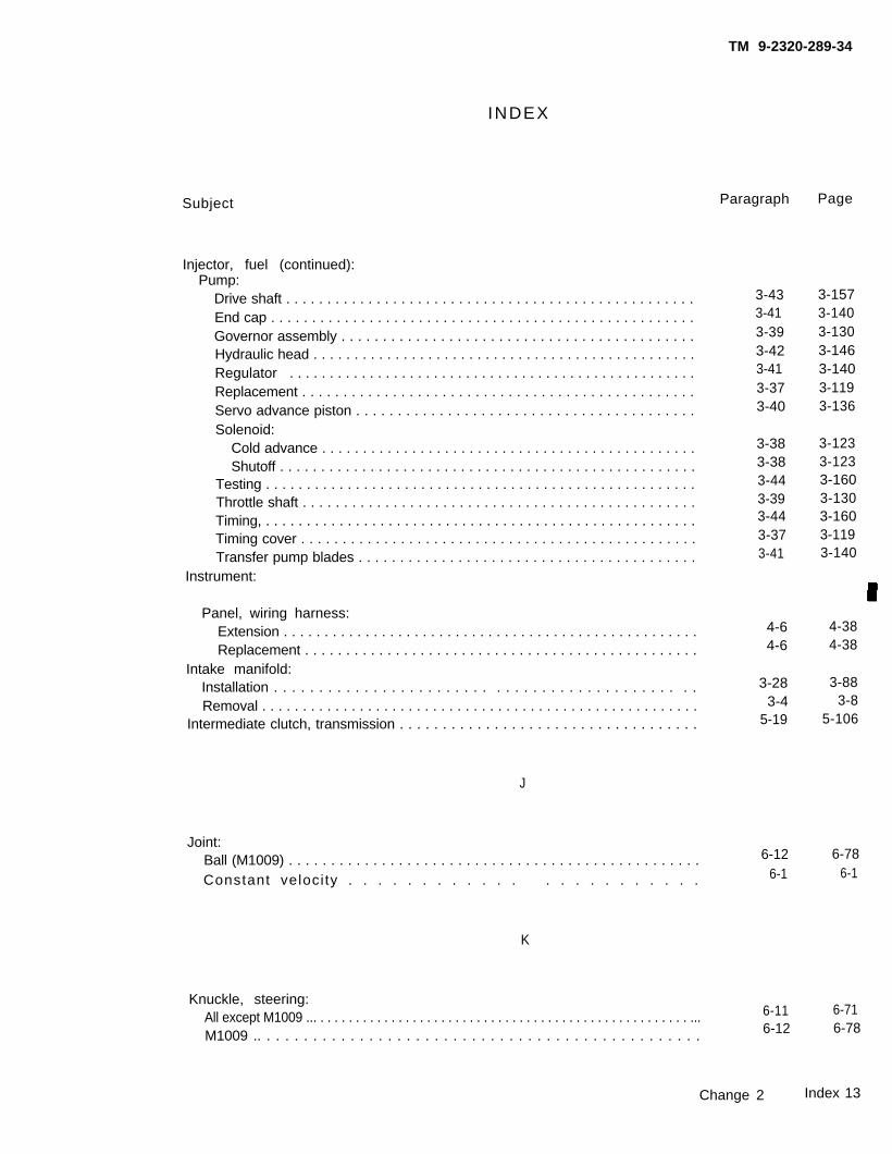
INDEX
Subject
TM 9-2320-289-34
Paragraph Page
Injector, fuel (continued):Pump:
Drive shaft . . . . . . . . . . . . . . . . . . . . . . . . . . . . . . . . . . . . . . . . . . . . . . . . . .End cap . . . . . . . . . . . . . . . . . . . . . . . . . . . . . . . . . . . . . . . . . . . . . . . . . . . .Governor assembly . . . . . . . . . . . . . . . . . . . . . . . . . . . . . . . . . . . . . . . . . . .Hydraulic head . . . . . . . . . . . . . . . . . . . . . . . . . . . . . . . . . . . . . . . . . . . . . . .Regulator . . . . . . . . . . . . . . . . . . . . . . . . . . . . . . . . . . . . . . . . . . . . . . . . . . .Replacement . . . . . . . . . . . . . . . . . . . . . . . . . . . . . . . . . . . . . . . . . . . . . . . .Servo advance piston . . . . . . . . . . . . . . . . . . . . . . . . . . . . . . . . . . . . . . . . .Solenoid:
Cold advance . . . . . . . . . . . . . . . . . . . . . . . . . . . . . . . . . . . . . . . . . . . . . .Shutoff . . . . . . . . . . . . . . . . . . . . . . . . . . . . . . . . . . . . . . . . . . . . . . . . . . .
Testing . . . . . . . . . . . . . . . . . . . . . . . . . . . . . . . . . . . . . . . . . . . . . . . . . . . . .Throttle shaft . . . . . . . . . . . . . . . . . . . . . . . . . . . . . . . . . . . . . . . . . . . . . . . .Timing, . . . . . . . . . . . . . . . . . . . . . . . . . . . . . . . . . . . . . . . . . . . . . . . . . . . . .Timing cover . . . . . . . . . . . . . . . . . . . . . . . . . . . . . . . . . . . . . . . . . . . . . . . .Transfer pump blades . . . . . . . . . . . . . . . . . . . . . . . . . . . . . . . . . . . . . . . . .
Instrument:
Panel, wiring harness:Extension . . . . . . . . . . . . . . . . . . . . . . . . . . . . . . . . . . . . . . . . . . . . . . . . . . .Replacement . . . . . . . . . . . . . . . . . . . . . . . . . . . . . . . . . . . . . . . . . . . . . . . .
Intake manifold:Installation . . . . . . . . . . . . . . . . . . . . . . . . . . . . . . . . . . . . . . . . . . . . . .Removal . . . . . . . . . . . . . . . . . . . . . . . . . . . . . . . . . . . . . . . . . . . . . . . . . . . . . .
Intermediate clutch, transmission . . . . . . . . . . . . . . . . . . . . . . . . . . . . . . . . . . .
J
Joint:Ball (M1009) . . . . . . . . . . . . . . . . . . . . . . . . . . . . . . . . . . . . . . . . . . . . . . . . .Constant velocity . . . . . . . . . . . . . . . . . . . . . . .
K
3-433-413-393-423-413-373-40
3-383-383-443-393-443-373-41
4-64-6
3-283-4
5-19
3-1573-1403-1303-1463-1403-1193-136
3-1233-1233-1603-1303-1603-1193-140
4-384-38
3-883-8
5-106
6-12 6-786-1 6-1
Knuckle, steering:All except M1009 ... . . . . . . . . . . . . . . . . . . . . . . . . . . . . . . . . . . . . . . . . . . . . . . . . . . . . ... 6-11 6-71
M1009 .. . . . . . . . . . . . . . . . . . . . . . . . . . . . . . . . . . . . . . . . . . . . . . . . 6-12 6-78
Change 2 Index 13

TM 9-2320-289-34
INDEX
Subject
L
Lifter, hydraulic valve:Installation . . . . . . . . . . . . . . . . . . . . . . . . . . . . . . . . . . . . . . . . . . . . . . . . . . . .Removal . . . . . . . . . . . . . . . . . . . . . . . . . . . . . . . . . . . . . . . . . . . . . . . . . . .
Lines, air conditioner (M1010) . . . . . . . . . . . . . . . . . . . . . . . . . . . . . . . . . . . . .Linkage, transmission:
Adjustment . . . . . . . . . . . . . . . . . . . . . . . . . . . . . . . . . . . . . . . . . . . . . . . . . . . .Maintenance . . . . . . . . . . . . . . . . . . . . . . . . . . . . . . . . . . . . . . . . . . . . . . . . . . .
Lock:Cylinder . . . . . . . . . . . . . . . . . . . . . . . . . . . . . . . . . . . . . . . . . . . . . . . . . . . ..Parking, transmission . . . . . . . . . . . . . . . . . . . . . . . . . . . . . . . . . . . . . . . . . .
Louver, air conditioner (M1010) . . . . . . . . . . . . . . . . . . . . . . . . . . . . . . . . . . . .
M
Paragraph Page
3-233-9
10-25
5-25-2
8-25-8
10-22
Maintenance forms and records . . . . . . . . . . . . . . . . . . . . . . . . . . . . . . . . . . . . 1-2Manifold, intake:
Installation . . . . . . . . . . . . . . . . . . . . . . . . . . . . . . . . . . . . . . . . . . . . . . . . . . . . 3-28Removal . . . . . . . . . . . . . . . . . . . . . . . . . . . . . . . . . . . . . . . . . . . . . . 3-4
Manufactured items, illustrated Iist of . . . . . . . . . . . . . . . . . . . . . . . . . . . . . . . . Appendix CMaterials and supplies list, expendable/durable . . . . . . . . . . . . . . . . . . . . . . . . Appendix BMetric:
Conversion chart . . . . . . . . . . . . . . . . . . . . . . . . . . . . . . . . . . . . . . . . . . . . . . .
System . . . . . . . . . . . . . . . . . . . . . . . . . . . . . . . . . . . . . . . . . . . . . . . . . . . . . . . 1-8Modulator assembly, vacuum . . . . . . . . . . . . . . . . . . . . . . . . . . . . . . . . . . . . . . 5-3Motor:
Engine coolant heater. . . . . . . . . . . . . . . . . . . . . . . . . . . . . . . . . . . . . . . 11-2Windshield wiper, . . . . . . . . . . . . . . . . . . . . . . . . . . . . . . . . . . . . . . . . . . . . . . 10-8
N
Nomenclature, names and designations, official . . . . . . . . . . . . . . . . . . . . . . .Nozzles, fuel injector:
Installation . . . . . . . . . . . . . . . . . . . . . . . . . . . . . . . . . . . . . . . . . . . . . . . . . . .Removal . . . . . . . . . . . . . . . . . . . . . . . . . . . . . . . . . . . . . . . . . . . . . . . . . .Testing .. . . . . . .. . . . . . . . . . . . . . . . . . . . . . . . . . .. .. . . . . . . . . . . . .
3-743-28
10-100
5-25-2
8-25-39
10-84
1-1
3-883-8C-1B-1
BackCover
1-25-6
11-210-26
1-5 1-1
3-27 3-853-5 3-11
3-36 3-116
Index 14

INDEX
S u b j e c t
O
TM 9-2320-289-34
Paragraph Page
Official nomenclature, names, and designations . . . . . . . . . . . . . . . . . . . . . . .Oil:
Cooler pipe, transmission:Return . . . . . . . . . . . . . . . . . . . . . . . . . . . . . . . . . . . . . . . . . . . . . . . . . . . . . .supply . . . . . . . . . . . . . . . . . . . . . . . . . . . . . . . . . . . . . . . . . . . . . . . . . . . . .
Pan, engine . . . . . . . . . . . . . . . . . . . . . . . . . . . . . . . . . . . . . . . . . . . . . . . ..Pressure testing, transmission . . . . . . . . . . . . . . . . . . . . . . . . . . . . . . . . . . . .Pump:
Engine, . . . . . . . . . . . . . . . . . . . . . . . . . . . . . . . . . . . . . . . . . . . . . . . . . . . . .Transmission . . . . . . . . . . . . . . . . . . . . . . . . . . . . . . . . . . . . . . . . . . . . . . . .
Seal:Axle drive pinion . . . . . . . . . . . . . . . . . . . . . . . . . . . . . . . . . . . . . . . . . . . . .Rear main . . . . . . . . . . . . . . . . . . . . . . . . . . . . . . . . . . . . . . . . . . . . . . . . . . .
Open door buzzer wiring harness . . . . . . . . . . . . . . . . . . . . . . . . . . . . . . . . . . .Outer seal, rear axle shaft (M1009) . . . . . . . . . . . . . . . . . . . . . . . . . . . . . . . . .
P
Panel:Cargo body:
Front . . . . . . . . . . . . . . . . . . . . . . . . . . . . . . . . . . . . . . . . . . . . . . . . . . . . . . .Side . . . . . . . . . . . . . . . . . . . . . . . . . . . . . . . . . . . . . . . . . . . . . . . . . . . . . . .
Control, air conditioner (M1010). . . . . . . . . . . . . . . . . . . . . . . . . . . . . . . . . .Wheel house:
Cargo body . . . . . . . . . . . . . . . . . . . . . . . . . . . . . . . . . . . . . . . . . . . . . . . . .Engine compartment . . . . . . . . . . . . . . . . . . . . . . . . . . . . . . . . . . . . . . . . . .
Parking lock, transmission.. . . . . . . . . . . . . . . . . . . . . . . . . . . . . . . . . . . . . . . .Passenger’s seat (M1009 and M1010) . . . . . . . . . . . . . . . . . . . . . . . . . . . . . .Personnel heater (warm air heater) . . . . . . . . . . . . . . . . . . . . . . . . . . . . . . . . .Pickup box . . . . . . . . . . . . . . . . . . . . . . . . . . . . . . . . . . . . . . . . . . . . . . . . . . . . . .Pin, band apply, selection check, transmission . . . . . . . . . . . . . . . . . . . . . . . .Pinion and bearings, axle drive:
Front:All except M1009 . . . . . . . . . . . . . . . . . . . . . . . . . . . . . . . . . . . . . . . . . . . . .M1009 . . . . . . . . . . . . . . . . . . . . . . . . . . . . . . . . . . . . . . . . . . . . . . . . . . ..
Rear:All except M1009, M1028A2, and M1028A3 . . . . . . . . . . . . . . . . . . . . . .M1009 . . . . . . . . . . . . . . . . . . . . . . . . . . . . . . . . . . . . . . . . . . . . . . M1028A2 and M1028A3 . . . . . . . . . . . . . . . . . . . . . . . . . . . . . . . . . . . . . .
1-5 1-1
5-45-4
3-325-11
3-335-15
6-103-344-126-14
5-165-16
3-1005-52
3-1065-72
6-683-1104-866-86
10-11 10-3610-11 10-3610-22 10-84
10-11 10-3610-6 10-215-8 5-39
10-16 10-5711-3 11-12
10-11 10-365-19 5-106
6-9 6-586-7 6-30
6-17 6 - 1 1 5 6-7 6-30
6-17.1 6-122 .1
Change 2 Index 15
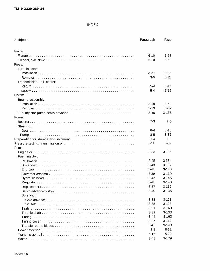
TM 9-2320-289-34
INDEX
Subject Paragraph Page
Pinion:Flange . . . . . . . . . . . . . . . . . . . . . . . . . . . . . . . . . . . . . . . . . . . . . . . . . . . . . . . .Oil seal, axle drive . . . . . . . . . . . . . . . . . . . . . . . . . . . . . . . . . . . . . . . . . . . . .
Pipes:Fuel injector:
Installation . . . . . . . . . . . . . . . . . . . . . . . . . . . . . . . . . . . . . . . . . . . . . . . . . .Removal, . . . . . . . . . . . . . . . . . . . . . . . . . . . . . . . . . . . . . . . . . . . . . . . . . . .
Transmission, oil cooler:Return, . . . . . . . . . . . . . . . . . . . . . . . . . . . . . . . . . . . . . . . . . . . . . . . . . . . . .supply . . . . . . . . . . . . . . . . . . . . . . . . . . . . . . . . . . . . . . . . . . . . . . . . ..
Piston:Engine assembly:
Installation . . . . . . . . . . . . . . . . . . . . . . . . . . . . . . . . . . . . . . . . . . . . . . . . . .Removal . . . . . . . . . . . . . . . . . . . . . . . . . . . . . . . . . . . . . . . . . . . . . . . . . . . .
Fuel injector pump servo advance . . . . . . . . . . . . . . . . . . . . . . . . . . . . . . . .Power:
Booster . . . . . . . . . . . . . . . . . . . . . . . . . . . . . . . . . . . . . . . . . . . . . . . . . . . . . . .Steering:
Gear . . . . . . . . . . . . . . . . . . . . . . . . . . . . . . . . . . . . . . . . . . . . . . . . . . . . .Pump . . . . . . . . . . . . . . . . . . . . . . . . . . . . . . . . . . . . . . . . . . . . . . . . . . . . . .
Preparation for storage and shipment . . . . . . . . . . . . . . . . . . . . . . . . . . . . . . .Pressure testing, transmission oil . . . . . . . . . . . . . . . . . . . . . . . . . . . . . . . . . . .Pump:
Engine oil . . . . . . . . . . . . . . . . . . . . . . . . . . . . . . . . . . . . . . . . . . . . . . . . . . . . .Fuel injector:
Calibration . . . . . . . . . . . . . . . . . . . . . . . . . . . . . . . . . . . . . . . . . . . . . . . . . .Drive shaft . . . . . . . . . . . . . . . . . . . . . . . . . . . . . . . . . . . . . . . . . . . . . . . . . .End cap . . . . . . . . . . . . . . . . . . . . . . . . . . . . . . . . . . . . . . . . . . . . . . . . . . . .Governor assembly . . . . . . . . . . . . . . . . . . . . . . . . . . . . . . . . . . . . . . . . . . .Hydraulic head . . . . . . . . . . . . . . . . . . . . . . . . . . . . . . . . . . . . . . . . . . . . . . .Regulator . . . . . . . . . . . . . . . . . . . . . . . . . . . . . . . . . . . . . . . . . . . . . . . . . . .Replacement . . . . . . . . . . . . . . . . . . . . . . . . . . . . . . . . . . . . . . . . . . . . . . . .Servo advance piston . . . . . . . . . . . . . . . . . . . . . . . . . . . . . . . . . . . . . . . . .Solenoid:
Cold advance . . . . . . . . . . . . . . . . . . . . . . . . . . . . . . . . . . . . . . . . . . . ...Shutoff . . . . . . . . . . . . . . . . . . . . . . . . . . . . . . . . . . . . . . . . . . . . . . . . . . .
Testing . . . . . . . . . . . . . . . . . . . . . . . . . . . . . . . . . . . . . . . . . . . . . . . . . . . . .Throttle shaft . . . . . . . . . . . . . . . . . . . . . . . . . . . . . . . . . . . . . . . . . . . . . . . .Timing, . . . . . . . . . . . . . . . . . . . . . . . . . . . . . . . . . . . . . . . . . . . . . . . . . . . . .Timing cover . . . . . . . . . . . . . . . . . . . . . . . . . . . . . . . . . . . . . . . . . . . . . . . .Transfer pump blades . . . . . . . . . . . . . . . . . . . . . . . . . . . . . . . . . . . . . . . . .
Power steering . . . . . . . . . . . . . . . . . . . . . . . . . . . . . . . . . . . . . ... . ....Transmission oil . . . . . . . . . . . . . . . . . . . . . . . . . . . . . . . . . . . . . . . . . . . . . . . .Water . . . . . . . . . . . . . . . . . . . . . . . . . . . . . . . . . . . . . . . . . . . . . . ....
6-10 6-686-10 6-68
3-27 3-853-5 3-11
5-4 5-165-4 5-16
3-193-133-40
7-3
8-48-51-4
5-11
3-33
3-453-433-413-393-423-413-373-40
3-383-383-443-393-443-373-41
8-55-153-48
3-613-37
3-136
7-5
8-168-32
1-15-52
3-106
3-1613-1573-1403-1303-1463-1403-1193-136
3-1233-1233-1603-1303-1603-1193-140
8-325-72
3-179
index 16

TM 9-2320-289-34
INDEX
Subject
R
Radiator support assembly. . . . . . . . . . . . . . . . . . . . . . . . . . . . . . . . . . . .Rear:
Axle:Backing plate (M1009) . . . . . . . . . . . . . . . . . . . . . . . . . . . . . . . . . . . . . . . .Bearing . . . . . . . . . . . . . . . . . . . . . . . . . . . . . . . . . . . . . . . . . . . . . . . .Differential:
All except M1009, M1028A2, and M1028A3 . . . . . . . . . . . . . . . . . . . . .M1009:
Repair . . . . . . . . . . . . . . . . . . . . . . . . . . . . . . . . . . . . . . . . . . . . . . . . . .Replacement . . . . . . . . . . . . . . . . . . . . . . . . . . . . . . . . . . . . . . . . . . . .
M1028A2 and M1028A3 . . . . . . . . . . . . . . . . . . . . . . . . . . . . . . . . . . . . .Drive:
Pinion and bearings:All except M1009, M1028A2, and M1028A3 . . . . . . . . . . . . . . . . . . .M1009, . . . . . . . . . . . . . . . . . . . . . . . . . . . . . . . . . . . . . . . . . . . . . . . . .M1028A2 and M1028A3 . . . . . . . . . . . . . . . . . . . . . . . . . . . . . . . . . . .
Pinion:Flange . . . . . . . . . . . . . . . . . . . . . . . . . . . . . . . . . . . . . . . . . . . . . . . . . .Oil seal . . . . . . . . . . . . . . . . . . . . . . . . . . . . . . . . . . . . . . . . . . . . . . . . .Outer seal . . . . . . . . . ... . . . . . . . . . . . . . . . . . . . . . . . . . . . .
Fender wiring harness . . . . . . . . . . . . . . . . . . . . . . . . . . . . . . . . . . . . . . . . .Replacement . . . . . . . . . . . . . . . . . . . . . . . . . . . . . . . . . . . . . . . . . . . . . . . .Shaft (M1009) . . . . . . . . . . . . . . . . . . . . . . . . . . . . . . . . . . . . . . . . . . . . . . .
Band, transmission . . . . . . . . . . . . . . . . . . . . . . . . . . . . . . . . . . . . . . . . . . . . .Main seal . . . . . . . . . . . . . . . . . . . . . . . . . . . . . . . . . . . . . . . . . . . . . . . . . . . . .Spring assembly:
Bushings . . . . . . . . . . . . . . . . . . . . . . . . . . . . . . . . . . . . . . . . . . . . . . . . . . .Replacement . . . . . . . . . . . . . . . . . . . . . . . . . . . . . . . . . . . . . . . . . . . . . . .
Unit end play, checking, transmission . . . . . . . . . . . . . . . . . . . . . . . . . . . . .Window, cab . . . . . . . . . . . . . . . . . . . . . . . . . . . . . . . . . . . . . . . . . . . . . . . . . .
Receiver-Dehydrator, air conditioner (M1010) . . . . . . . . . . . . . . . . . . . . . . . . .Records and maintenance forms . . . . . . . . . . . . . . . . . . . . . . . . . . . . . . . . . . . .References . . . . . . . . . . . . . . . . . . . . . . . . . . . . . . . . . . . . . . . . . . . . . . . . . . . . . .Regulator:
Current/voltage (M1010) . . . . . . . . . . . . . . . . . . . . . . . . . . . . . . . . . . . . . . . .Fuel injector pump . . . . . . . . . . . . . . . . . . . . . . . . . . . . . . . . . . . . . . . . . . . . .
Relay,current/voltage regulator (M1010) . . . . . . . . . . . . . . . . . . . . . . . . . . . . .Repair parts . . . . . . . . . . . . . . . . . . . . . . . . . . . . . . . . . . . . . . . . . . . . . . . . . . . . .Reporting equipment improvement recommendations (EIRs) . . . . . . . . . . . .Return pipe, transmission oil cooler . . . . . . . . . . . . . . . . . . . . . . . . . . . . . . . . .Rocker arm and cover:
Installation . . . . . . . . . . . . . . . . . . . . . . . . . . . . . . . . . . . . . . . . . . . . . . . . . .Removal . . . . . . . . . . . . . . . . . . . . . . . . . . . . . . . . . . . . . . . . . . . . . . . . ...
Paragraph Page
10-2
6-146-14
6-15
6-166-5
6-15.1
6-176-7
6-17.1
6-106-106-14
4-9.16-136-145-193-34
6-206-205-18
10-1210-27
1-2Appendix A
4-43-414-41-91-65-4
3-263-6
Change 2
10-2
6-866-86
6 - 9 2
6-1046-15
6-103 .0
6 - 1 1 5 6-30
6-122 .1
6-686-686-86
4-68.16-836-86
5-1063-110
6-1316-1315-10310-43
10-1081-1A-1
4-243-1404-24
1-21-1
5-16
3-813-14
Index 17

TM 9-2320-289-34
INDEX
Subject
Rod, connecting, piston:Bearing:
Installation . . . . . . . . . . . . . . . . . . . . . . . . . . . . . . . . . . . . . . . . . . . . . . . . . .Removal . . . . . . . . . . . . . . . . . . . . . . . . . . . . . . . . . . . . . . . . . . . . . . . . . . . .
Installation . . . . . . . . . . . . . . . . . . . . . . . . . . . . . . . . . . . . . . . . . . . . . . . . . . . .Removal . . . . . . . . . . . . . . . . . . . . . . . . . . . . . . . . . . . . . . . . . . . . . . . . . . . . . .
Rotor, brake. . . . . . . . . . . . . . . . . . . . . . . . . . . . . . . . . . . . . . . . . . . .
s
Schematics, wiring . . . . . . . . . . . . . . . . . . . . . . . . . . . . . . . . . . . . . . . . . .Scope . . . . . . . . . . . . . . . . . . . . . . . . . . . . . . . . . . . . . . . . . . . . . . . . . . . . . . . . . .Seal, rear main . . . . . . . . . . . . . . . . . . . . . . . . . . . . . . . . . . . . . . . .Seats:
Bench:All except M1009 and M1010. . . . . . . . . . . . . . . . . . . . . . . . . . . . . . . . . . .M1009 . . . . . . . . . . . . . . . . . . . . . . . . . . . . . . . . . . . . . . . . . . . . . . .
Driver’s (M1009 and M1010) . . . . . . . . . . . . . . . . . . . . . . . . . . . . . . . . . . . . .Passenger’s (M1009 and M1010) . . . . . . . . . . . . . . . . . . . . . . . . . . . . . . . . .
Servicing, air conditioner. . . . . . . . . . . . . . . . . . . . . . . . . . . . . . . . . . . . . . . .Servo:
Advance piston, fuel injector pump . . . . . . . . . . . . . . . . . . . . . . . . . . . . . . . ..Assembly, transmission:
Front . . . . . . . . . . . . . . . . . . . . . . . . . . . . . . . . . . . . . . . . . . . . .Rear . . . . . . . . . . . . . . . . . . . . . . . . . . . . . . . . . . . . . . . . . . . . . . . . . . . . . . .
Shaft:Axle:
Front . . . . . . . . . . . . . . . . . . . . . . . . . . . . . . . . . . . . . . . . . . . . . . . . . . . . . .Rear (M1009) . . . . . . . . . . . . . . . . . . . . . . . . . . . . . . . . . . . .
Fuel injector pump drive.... . . . . . . . . . . . . . . . . . . . . . . . . . . . . . . . . . . . . .Steering, . ., . . . . . . . . . . . . . . . . . . . . . . . . . . . . . . . . . . . . . . . . . . . . . . . . . .
Shipment, preparation for . . . . . . . . . . . . . . . . . . . . . . . . . . . . . . . . . . . . . . . . .Solenoid:
Detent, transmission. . . . . . . . . . . . . . . . . . . . . . . . . . . . . . . . . . . . . . . . .Fuel injector pump:
Cold advance . . . . . . . . . . . . . . . . . . . . . . . . . . . . . . . . . . . . . . . . . . . . . . .Shutoff . . . . . . . . . . . . . . . . . . . . . . . . . . . . . . . . . . . . . . . . . . . . . . . . . . . .
Special tools . . . . . . . . . . . . . . . . . . . . . . . . . . . . . . . . . . . . . . . . . . . . . . . . . . . .Splash guard . . . . . . . . . . . . . . . . . . . . . . . . . . . . . . . . . . . . . . . . . . . . . . . . . . . .Spring assembly:
Front . . . . . . . . . . . . . . . . . . . . . . . . . . . . . . . . . . . . . . . . . . . . . . . . . . . . . . . . .Rear . . . . . . . . . . . . . . . . . . . . . . . . . . . . . . . . . . . . . . . . . . . . . . . . . . . . . . . . .
Paragraph Page
3-19 3-613-13 3-373-19 3-613-13 3-37
7-2 7-2
Appendix E1-1
3-34
10-1310-1710-1610-1610-21
3-40
5-105-9
6-46-143-43
8-31-4
5-7
3-383-38
1-910-6
6-196-20
E-11-1
3-110
10-4610-6110-5710-5710-79
3-136
5-495-44
6-126-86
3-1578-14
1-1
5-26
3-1233-123
1-210-21
6-1246-131
Index 18

TM 9-2320-289-34
INDEX
Subject
Sprockets, timing:Installation . . . . . . . . . . . . . . . . . . . . . . . . . . . . . . . . . . . . . . .Removal . . . . . . . . . . . . . . . . . . . . . . . . . . . . . . . . . . . . . . . . . . . . . . . . . . . . . .
Starter testing and repair . . . . . . . . . . . . . . . . . . . . . . . . . . . . . . . . . . . . . . .Steering:
Arm:All except M1009 . . . . . . . . . . . . . . . . . . . . . . . . . . . . . . . . . . . . . . . . . . . .M1009 . . . . . . . . . . . . . . . . . . . . . . . . . . . . . . . . . . . . . . . . . . . . . . . . . . . . . .
Ball point . . . . . . . . . . . . . . . . . . . . . . . . . . . . . . . . . . . . . . . . . . . . . . . . . . . . . .Column . . . . . . . . . . . . . . . . . . . . . . . . . . . . . . . . . . . . . . . . . . . . . . . . . . . . . . .Knuckle:
All except M1009 . . . . . . . . . . . . . . . . . . . . . . . . . . . . . . . . . . . . . . . . . . . . .M1009 . . . . . . . . . . . . . . . . . . . . . . . . . . . . . . . . . . . . . . . . . . . . . . . . . . ..
Power:Gear . . . . . . . . . . . . . . . . . . . . . . . . . . . . . . . . . . . . . . . . . . . . . . . . . . . . . . .Pump . . . . . . . . . . . . . . . . . . . . . . . . . . . . . . . . . . . . . . . . . . . . . . . . . . . . . .
Shaft . . . . . . . . . . . . . . . . . . . . . . . . . . . . . . . . . . . . . . . . . . . . . . . . . . . . . . . . .STE/lCE troubleshooting . . . . . . . . . . . . . . . . . . . . . . . . . . . . . . . . . . . . . . . . . .Storage, preparation . . . . . . . . . . . . . . . . . . . . . . . . . . . . . . . . . . . . . . . . . .Supplies and materials list, expendable/durable . . . . . . . . . . . . . . . . . . . . . . .Supply pipe, transmission oil cooler . . . . . . . . . . . . . . . . . . . . . . . . . . . . . . . . .Support, radiator . . . . . . . . . . . . . . . . . . . . . . . . . . . . . . . . . . . . . . . . . . . . . . . . .Switch:
Dimmer . . . . . . . . . . . . . . . . . . . . . . . . . . . . . . . . . . . . . . . . . . . . . . . . . . . . . . .Directional signal . . . . . . . . . . . . . . . . . . . . . . . . . . . . . . . . . . . . . . . . . . . . . . .Flame:
Detector, warm air heater.. . . . . . . . . . . . . . . . . . . . . . . . . . . . . . . . . . . .Engine coolant heater . . . . . . . . . . . . . . . . . . . . . . . . . . . . . . . . . . . . . . . . .
Ignition . . . . . . . . . . . . . . . . . . . . . . . . . . . . . . . . . . . . . . . . . . . . . . . . . . . . . . .
Tables:Air conditioning system performance . . . . . . . . . . . . . . . . .Axles:
Pinion settings.. . . . . . . . . . . . . . . . . . . . . . . . . . . . .Shim requirements:
Drive pinion:All except M10109 , M1028A2, and M1028A3 . . . . . .M1009 . . . . . . . . . . . . . . . . . . . . . . . . . . . . . . . . . . . . .M1028A2 and M1028A3 . . . . . . . . . . . . . . . . . . . . . .
Side bearing . . . . . . . . . . . . . . . . . . . . . . . . . . . . . . . . . . .
. . . . . . . . . . . .
. . . . . . . . . . . .
. . . . . . . . . . .
. . . . . . . . . . . . . . . . . . . . .. . . . . . . . . . . .
Paragraph
3-213-114-5
Page
3-683-334-26
6-11 6-716-12 6-786-12 6-78
8-2 8-2
6-11 6-716-12 6-78
8-48-58-32-41-4
Appendix B5-4
10-2
8-168-328-142-51
1-1B-1
5-1610-2
4-13 4-914-14 4-94
11-3 11-1211-2 11-24-13 4-91
Table 10-1
Table 6-3
Table 6-4Table 6-2
Table 64.1Table 6-1
10-76
6-64
6 - 1 2 1 6-37
6-122 .7 6-19
Change 2 Index 19

TM 9-2320-289-34
INDEX
Subject
Tables (continued):Brakes:
Drum diameter . . . . . . . . . . . . . . . . . . . . . . . . . . . . . . . . . . . . . . . . . . . . . . .Rotor thickness . . . . . . . . . . . . . . . . . . . . . . . . . . . . . . . . . . . . . . . . . . . . . .
Drivebelt tension specifications . . . . . . . . . . . . . . . . . . . . . . . . . . . . . . . . . . .Equipment data ., . . . . . . . . . . . . . . . . . . . . . . . . . . . . . . . . . . . . . . . . . . . . . .Manufactured items part number cross-reference . . . . . . . . . . . . . .Piston diameters . . . . . . . . . . . . . . . . . . . . . . . . . . . . . . . . . . . . . . . . . . . . . . .Torque specifications, standard . . . . . . . . . . . . . . . . . . . . . . . . . . . . . . . . . . .Transmission:
Malfunction related to oil pressure . . . . . . . . . . . . . . . . . . . . . . . . . . . . . .Preliminary checking procedure, oil pressure . . . . . . . . . . . . . . . . . . . . .Unit end play selective washers:
Front . . . . . . . . . . . . . . . . . . . . . . . . . . . . . . . . . . . . . . . . . . . . . . . ...Rear . . . . . . . . . . . . . . . . . . . . . . . . . . . . . . . . . . . . . . . . . . . . . . . . . . . . .
Troubleshooting:Electrical . . . . . . . . . . . .. . . . . . . . . . . . . . . . . . . . . . . . . . . . . . . . . . . .Mechanical, . . . . . . . . . . . . . . . . . . . . . . . . . . . . . . . . . . . . . . . . . . . . . . . . .
Wheel alinement specifications . . . . . . . . . . . . . . . . . . . . . . . . . . . . . . . . . . .Taillight wiring harness (M1010 and M1031) . . . . . . . . . . . . . . . . . . . . . . . . . .Testing:
Air conditioner . . . . . . . . . . . . . . . . . . . . . . . . . . . . . . . . . . . . . .....Alternator output:
All except M1010 . . . . . . . . . . . . . . . . . . . . . . . . . . . . . . . . . . . . . . . . . . . . .M1010 . . . . . . . . . . . . . . . . . . . . . . . . . . . . . . . . . . . . . . . . . . . . . . . . . . ..
Engine compression, . . . . . . . . . . . . . . . . . . . . . . . . . . . . . . . . . . . . . . . . . . .Fuel injector:
Nozzle . . . . . . . . . . . . . . . . . . . . . . . . . . . . . . . . . . . . . . . . . . . . . . . . . . . . . .Pump . . . . . . . . . . . . . . . . . . . . . . . . . . . . . . . . . . . . . . . . . . . . . . . . . . . . . .
Starter . . . . . . . . . . . . . . . . . . . . . . . . . . . . . . . . . . . . . . . . . . . . . . . . . . . . . . .Transmission oil pressure . . . . . . . . . . . . . . . . . . . . . . . . . . . . . . . . . . . . . . . .
Throttle shaft, fuel injector pump . . . . . . . . . . . . . . . . . . . . . . . . . . . . . . . . . . .Timing:
Chain and sprockets:Installation . . . . . . . . . . . . . . . . . . . . . . . . . . . . . . . . . . . . . . . . . . . . . . . . . .Removal . . . . . . . . . . . . . . .. . . . . . . . . . . . . . . . . . . . .
Fuel injector pump . . . . . . . . . . . . . . . . . . . . . . . . . . . . . . . . . . . . . . . . . .Tools, common and special., . . . . . . . . . . . . . . . . . . . . . . . . . . . . . . . . . . . . . .Top assembly .(M1009):
Replacement . . . . . . . . . . . . . . . . . . . . . . . . . . . . . . . . . . . . . . . . . . . . . . . . . .W i n d o w , . . . . . . . . . . . . . . . . . . . . . . . . . . . . . . . . . . . . . . . . .
Torque:Converter . . . . . . . . . . . . . . . . . . . . . . . . . . . . . . . . . . . . . . . . . . . . . . . . . . . .Limits . . . . . . . . . . . . . . . . . . . . . . . . . . . . . . . . . . . . . . . . . . . . . . . . . . . . . . . .
Paragraph
Table 7-1Table 7-2Table .D-2Table 1-1Table C-lTable 3-1Table D-1
Table 5-2Table 5-1
Table 5-3Table 5-4
Table 2-2Table 2-1Table G-1
4-9
10-20
4-24-33-2
3-363-44
4-55-113-39
3-213-113-44
1-9
10-1510-4
5-12Appendix D
Page
7-27-3D-21-4C-1
3-41D-1
5-545-53
5-705-104
2-412-10G-1
4-66
10-74
4-24-14
3-2
3-1163-1604-265-52
3-130
3-683-33
3-1601-2
10-5210-10
5-56D-1
Index 20

TM 9-2320-289-34
I N D E X
Subject
Torsional damper:Installation . . . . . . . . . . . . . . . . . . . . . . . . . . . . . . . . . . . . . . . . . . . . . . .Removal . . . . . . . . . . . . . . . . . . . . . . . . . . . . . . . . . . . . . . . . . . . . . . . . .
Transfer case:All except M1028A1, M1028A2, and M1031 . . . . . . . . . . . . . . . . . . . . . . . . .M1028A1, M1028A2, and M1031 . . . . . . . . . . . . . . . . . . . . . . . . . . . . . . . . . .
Transfer pump blades, fuel injector pump . . . . . . . . . . . . . . . . . . . . . . . . . . . .Transmission:
Band apply pin selection check . . . . . . . . . . . . . . . . . . . . . . . . . . . . . . . . . . .Center support and gear unit . . . . . . . . . . . . . . . . . . . . . . . . . . . . . . . . . . . . .Clutch assembly:
Direct . . . . . . . . . . . . . . . . . . . . . . . . . . . . . . . . . . . . . . . . . . . . . . . . . . . . . .Forward . . . . . . . . . . . . . . . . . . . . . . . . . . . . . . . . . . . . . . . . . . . . . . . . . . . .Intermediate . . . . . . . . . . . . . . . . . . . . . . . . . . . . . . . . . . . . . . . . . . . . . . . . .
Control valve assembly . . . . . . . . . . . . . . . . . . . . . . . . . . . . . . . . . . . . . . . . . .Detent solenoid . . . . . . . . . . . . . . . . . . . . . . . . . . . . . . . . . . . . . . . . . . . . . . . .Direct clutch assembly . . . . . . . . . . . . . . . . . . . . . . . . . . . . . . . . . . . . . . . . . .Downshift electrical connector . . . . . . . . . . . . . . . . . . . . . . . . . . . . . . . . . . . .Fill tube assembly . . . . . . . . . . . . . . . . . . . . . . . . . . . . . . . . . . . . . . . . . . . . .Forward clutch assembly . . . . . . . . . . . . . . . . . . . . . . . . . . . . . . . . . . . . . . . .Front:
Band . . . . . . . . . . . . . . . . . . . . . . . . . . . . . . . . . . . . . . . . . . . . . . . . . . . . . . .Servo assembly . . . . . . . . . . . . . . . . . . . . . . . . . . . . . . . . . . . . . . . . . . . . . .
Governor assembly . . . . . . . . . . . . . . . . . . . . . . . . . . . . . . . . . . . . . . . . . . . . .Holding fixture . . . . . . . . . . . . . . . . . . . . . . . . . . . . . . . . . . . . . . . . . . . . . . . . .Intermediate clutch assembly . . . . . . . . . . . . . . . . . . . . . . . . . . . . . . . . . . . .Linkage . . . . . . . . . . . . . . . . . . . . . . . . . . . . . . . . . . . . . . . . . . . . . . . . . . . . . . .O i l :
Cooler pipe:Return, . . . . . . . . . . . . . . . . . . . . . . . . . . . . . . . . . . . . . . . . . . . . . . . . . . .supply . . . . . . . . . . . . . . . . . . . . . . . . . . . . . . . . . . . . . . . . . . . . . . . . . . . .
Pressure testing . . . . . . . . . . . . . . . . . . . . . . . . . . . . . . . . . . . . . . . . . . . . . .Pump . . . . . . . . . . . . . . . . . . . . . . . . . . . . . . . . . . . . . . . . . . . . . . . . . . . . . .
Parking lock . . . . . . . . . . . . . . . . . . . . . . . . . . . . . . . . . . . . . . . . . . . . . . . . . . .Rear:
Band . . . . . . . . . . . . . . . . . . . . . . . . . . . . . . . . . . . . . . . . . . . . . . . . . ..Servo assembly . . . . . . . . . . . . . . . . . . . . . . . . . . . . . . . . . . . . . . . . . . . . . .
Replacement . . . . . . . . . . . . . . . . . . . . . . . . . . . . . . . . . . . . . . . . . . . . . . . . . .Unit end play, checking:
Front . . . . . . . . . . . . . . . . . . . . . . . . . . . . . . . . . . . . . . . . . . . . . . . . . . . . . .Rear. . . . . . . . . . . . . . . . . . . . . . . . . . . . . . . . . . . . . . . . . . . . . . . . .
Paragraph Page
3-223-10
5-215-223-41
5-95-19
5-175-165-19
5-75-7
5-175-65-3
5-16
5-175-10
5-55-135-19
5-2
3-693-29
5-1325-1603-140
5-445-106
5-925-82
5-1065-265-265-925-24
5-65-82
5-925-495-205-65
5-1065-2
5-4 5-165-4 5-16
5-11 5-525-15 5-72
5-8 5-39
5-19 5-1065-9 5-44
5-12 5-56
5-14 5-685-18 5-103
Change 1 Index 21

TM 9-2320-289-34
INDEX
Subject Paragraph
Transmission (continued):Servo assembly:
Front, . . . . . . . . . . . . . . . . . . . . . . . . . . . . . . . . . . . . . . . . . . . . . . . . . . . . . . 5-10Rear . . . . . . . . . . . . . . . . . . . . . . . . . . . . . . . . . . . . . . . . . . . . . . . . . . . . . . . 5-9
Vacuum:
Modulator assembly . . . . . . . . . . . . . . . . . . . . . . . . . . . . . . . . . . . . . . . . . .
Troubleshooting:Electrical . . . . . . . . . . . . . . . . . . . . . . . . . . . . . . . . . . . . . . . . . . . . . . . . . . . . . .General . ., . . . . . . . . . . . . . . . . . . . . . . . . . . . . . . . . . . . . . . . . . . . . . . . . . . . .Malfunction instructions, electrical . . . . . . . . . . . . . . . . . . . . . . . . . . . . . . . . .Mechanica l . . . . . . . . . . . . . . . . . . . . . . . . . . . . .STE/lCE . . . . . . . . . . . . . . . . . . . . . . . . . . . . . . . . . . . . . . . . . . . . . . . . . . . . . .Symptom index:
Electrical . . . . . . . . . . . . . . . . . . . . . . . . . . . . . . . . . . . . . . . . . . . . . . . . . . . .Mechanical . . . . . . . . . . . . . . . . . . . . . . . . . . . . . . . . . . . . . . . . . . . . . . . . . .
V
5-3
Table 2-22-12-2
Table 2-12-4
2-32-3
Vacuum, transmission:
Modulator assembly. . . .. . . . . . . . . . . . . . . . . . . . . . . . . . . . . . . . . . . . . . . . . . . 5-3Valve:
Engine:Installation . . . . . . . . . . . . . . . . . . . . . . . . . . . . . . . . . . . . . . . . . . . . . . . . . . 3-24Lifter, hydraulic:
Installation . . . . . . . . . . . . . . . . . . . . . . . . . . . . . . . . . . . . . . . . . . . . . . . . 3-23Removal . . . . . . . . . . . . . . . . . . . . . . . . . . . . . . . . . . . . . . . . . . . . . . . . . . 3-9
Removal . . . . . . . . . . . . . . . . . . . . . . . . . . . . . . . . . . . . . . . . . . . . . . . . 3-8Expansion, air conditioner (M1010) . . . . . . . . . . . . . . . . . . . . . . . . . . . . . . . . 10-27Transmission:
Control .. . . . . . . . . . . . . . . . . . . . . . . . . . . . . . .. . . . . . . . . . . . .. ... . .Vacuum . . . . . . . . . . . . . . .. . . . . . .. . . . . . . . . . . .. . . . ...........
Velocity joint, constant . . . . . . .. . . . . . . . . . . . . . . . . . .. . . . . . . . . . . . . . . . Voltage regulator, current (M1010
Relay. . . . . . . . . . . . . . . . . . . . . . . . . . . . . . . . . . . . . . . . . . . . . . . . . .Replacement .. . . . . . . . . . . . . . . . . . . . . . . . . . . . . . . . . . . . . . . . . . . . . . . . . . . . . ..
5-73-46
6-1
4 - 44-4
Page
5-495-44
5-6
2-412-12-2
2-102-51
2-92-6
5-6
3-76
3-743-283-24
10-108
5-263-175
6-1
4-244-24
Index 22 Change 2

TM 9-2320-289-34
INDEX
Subject Paragraph Page
W
Warm air heater . . . . . . . . . . . . . . . . . . . . . . . . . . . . . . . . . . . . . . . . . . . . . . . . .Warranty information . . . . . . . . . . . . . . . . . . . . . . . . . . . . . . . . . . . . . . . . . . . . .Water pump . . . . . . . . . . . . . . . . . . . . . . . . . . . . . . . . . . . . . . . . . . . . . . . .Wheel alinement . . . . . . . . . . . . . . . . . . . . . . . . . . . . . . . . . . . . . . . . . . . . . . . . .Wheel house panel:
Cargo body . . . . . . . . . . . . . . . . . . . . . . . . . . . . . . . . . . . . . . . . . . . . . . . . . . .Engine compartment . . . . . . . . . . . . . . . . . . . . . . . . . . . . . . . . . . . . . . . . . . . .
Window:Cab rear . . . . . . . . . . . . . . . . . . . . . . . . . . . . . . . . . . . . . . . . . . . . . . . . . . . . . .Top assembly (M1009) . . . . . . . . . . . . . . . . . . . . . . . . . . . . . . . . . . . . . . . . . .
Windshield:Replacement . . . . . . . . . . . . . . . . . . . . . . . . . . . . . . . . . . . . . . . . . . . . . . . . . .Wiper motor . . . . . . . . . . . . . . . . . . . . . . . . . . . . . . . . . . . . . . . . . . . . .
Wiring:Diagrams and schematics . . . . . . . . . . . . . . . . . . . . . . . . . . . . . . . . . . . .Harness:
Body . . . . . . . . . . . . . . . . . . . . . . . . . . . . . . . . . . . . . . . . . . . . . . . . . . . . . . .Cab heater control . . . . . . . . . . . . . . . . . . . . . . . . . . . . . . . . . . . . . . . . . . .Engine:
Diagnostic . . . . . . . . . . . . . . . . . . . . . . . . . . . . . . . . . . . . . . . . . . . . . . . . .Replacement . . . . . . . . . . . . . . . . . . . . . . . . . . . . . . . . . . . . . . . . . . . . . .
Front . . . . . . . . . . . . . . . . . . . . . . . . . . . . . . . . . . . . . . . . . . . . . . . . . . .Glow plug . . . . . . . . . . . . . . . . . . . . . . . . . . . . . . . . . . . . . . . . . . . . . . . . . . .Instrument panel:
Extension . . . . . . . . . . . . . . . . . . . . . . . . . . . . . . . . . . . . . . . . . . . . . . . . .Replacement . . . . . . . . . . . . . . . . . . . . . . . . . . . . . . . . . . . . . . . . . . . . . .
Open door buzzer . . . . . . . . . . . . . . . . . . . . . . . . . . . . . . . . . . . . . . . . . . . .Rear Fender (M1028A2 and M1028A3) . . . . . . . . . . . . . . . . . . . . . . . . . . .Taillight (M1010 and M1031) . . . . . . . . . . . . . . . . . . . . . . . . . . . . . . . . . . .
11-31-7
3-48Appendix G
10-1110-6
10-1210-4
10-410-8
Appendix E
4-84-12
4-124-10
4-74-11
4-64-6
4-124-9.1
4-9
11-121-2
3-179G-1
10-3610-21
10-4310-10
10-1010-26
E-1
4-604-86
4-864-694-534-83
4-384-384-86
4-68.1 4-66
* US GOVERNMENT PRINTING OFFICE 1993-746-017/80031 C h a n g e 2 lndex23/(lndex 24 blank)

By Order of the Secretary of the Army:
Official:
GORDON R. SULLIVANGeneral, United States Army
Chief of Staff
MILTON H. HAMILTONAdministrative Assistant to the
Secretary of the Army02692
By Order of the Secretary of the Air Force;MERRILL A. McPEAK
General, United States Air ForceChief of Staff
Official;CHARLES C. McDONALD
General, United States Air ForceCommander, Air Force Logistics Command
By Order of the Marine Corps:H. E. REESE
Deputy for SupporlMarine Corps Research, Development and
Acquisition Command
Distr ibut ion:To be distributed in accordance with DA Form 12-38-E, Block No. 372, Unit, Direct Support and
General Support maintenance requirements for TM 9-2320-289-34.
3

TM 9-2320-289-34

TM 9-2320-289-34


PIN: 053644-002